

Page 1
™
SelectSweep
87522-48
Operator and Parts Manual
Manual del Operador y de Accessorios
Nilfisk-Advance Model 56100874
English
Espanol
revised 4/00
Form Number 56041492
!
Page 2

IMPORTANT
SAFETY
INSTRUCTIONS
1. The push sweeper comes to you partially
assembled. Before operation, you must attach the
handle and side broom to the main sweeper
housing.
2. Unpack the push sweeper from the shipping carton
and place the unit on a flat surface.
3. Remove dirt hopper from sweeper frame.
4. Remove parts which may have been packaged in
the dirt hopper.
5. Before shipping carton is discarded, make sure all
loose parts and literature have been removed.
To reduce the
risk of fire
orpersonal injury:
1. Do not pick up toxic, carcinogenic, combustible,
or other hazardous materials such as asbestos,
arsenic, barium, beryllium, lead, pesticides, or
other health endangering materials.
2. Do not pick-up burning cigarettes or other
smoking materials, ashes, matches or similar
materials.
3. To avoid personal injury, use heavy gloves when
removing glass, metal or other sharp materials
from the dirt hopper.
4. The dirt hopper should be emptied after each use.
5. This push sweeper is not designed for use with
liquids.
6. Do not expose to rain. Store indoors.
7. Do not allow to be used as a toy. Close attention
is necessary when used by or near children.
8. The operation of a utility sweeper can result in
foreign substances being blown into the eyes.
Always wear safety goggles when operating
sweeper.
9. Stay alert. Watch what you are doing and use
common sense. Do not use push sweeper when
tired, distracted, or under the influence of drugs,
alcohol, or medication causing diminished control.
Please read and save these instructions. Read carefully before attempting to assemble, install, operate or maintain
the products described. Protect yourself and others by observing all safety information. Failure to comply with
instructions could result in personal injury and/or property damage! Retain instructions for future reference.
Description
The push sweeper is designed as a time saving system for the cleanup of large floor areas. The push
sweeper pushes easily and cleans a 27” (68.58 cm) path. Sweeper features durable structural foam
chassis construction, large capacity hopper, 10” (25.4 cm) semi-pneumatic, non-slip wheels, side broom
for cleaning along walls, curbs and under shelving, and a broom height adjustment for different
surfaces and wear. Unit requires no regular maintenance.
Commercial/Industrial Use
ALWAYS
WEAR EYE
PROTECTION
Specifications
8 Gal. 19” Wide 13 “ Dia. 10”
(25.4 cm) 27” 45Lbs.
(30.28 liters) (48.26 cm
) (33.02 cm) Semi-Pneumatic (68.58 cm) (20.4 kg)
Non-Slip
Main Side Main Sweeping
Capacity Broom Broom Wheels Width Weight
2
Model: 56100874
Page 3
3
Assembly
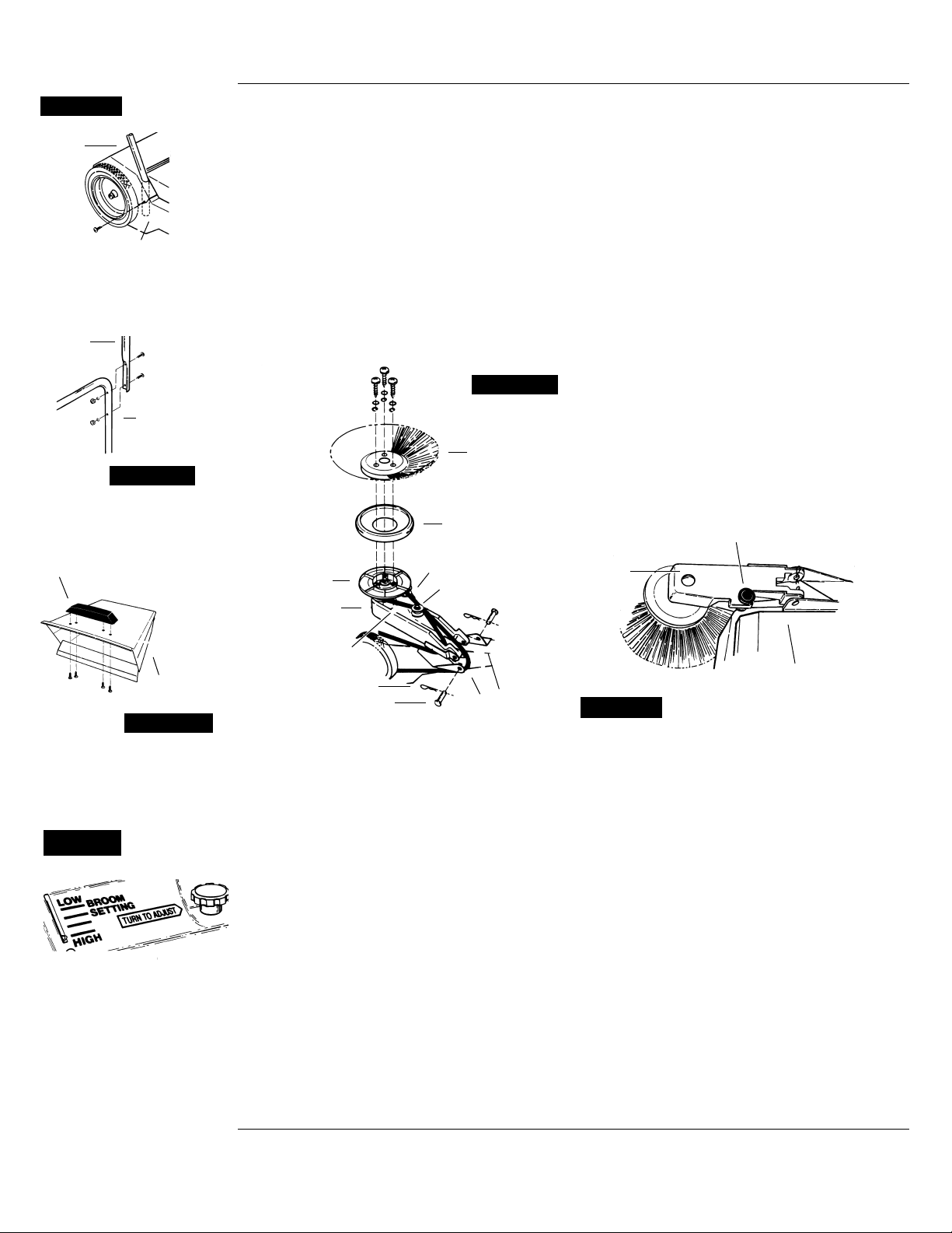
ASSEMBLING HANDLE
1. Place ends of lower handle into holes of sweeper
frame. Attach with screws (see
Figure 1).
2. Attach upper handle to lower handle using
machine screws, lockwashers, and nuts (see
Figure 2).
3. Hopper handle should be attached to the dirt
hopper with screws provided (see Figure 3).
ASSEMBLING SIDE BROOM
1. Drive belt should be positioned on the pulley when
received. Check to ensure belt is on the pulley,
and between belt guides.
2. With the side arm positioned as shown in Figure 4,
place the belt between the walls of the side broom
arm. Place the outside tracking belt over the rear
wheel and above the mounting bracket. The inside
tracking belt must be UNDER the mounting
bracket.
3. Attach the side broom arm to the mounting
bracket, by aligning the holes in the arm with the
holes in the mounting bracket. Insert clevis pins
and secure with hairpin clips.
4. Place side broom bumper on the side broom
pulley with the outside flange toward side broom.
Attach side broom to the side broom pulley with
screws, lockwasher and washers.
5. Lower side broom arm and replace hopper.
6. If side broom rotates in the wrong direction, the
belt is not installed correctly.
Operation
MAIN BROOM
Refer to Figure 5.
1. The main broom has been preset at the factory for
maximum sweeping efficiency.
2. If adjustments are required for surfaces or wear,
this can be done by turning the adjustment knob.
The height indicator will show the position of the
broom as you make your adjustment (Figure 5).
3. For best operating performance, the bristles of the
broom should just touch the floor.
NOTE: If the main broom is set too low, the sweeper
will be hard to push.
SIDE BROOM
Refer to Figure 6.
1. The side broom should be lowered and used when
sweeping along curbs or walls; it may also be
used when sweeping open areas.
2. Side broom height should be adjusted to have
approximately
1
/3of the bristles touching the floor.
Adjustment can be made by turning the
adjustment knob.
OPERATING PUSH SWEEPER
Push sweeper forward at normal walking speed; it
does not operate when pulled backwards.
Figure 1
Hopper
Handle
▲
▲
Lower
Handle
▲
Sweeper
Frame
Lower
Handle
▲
▲
Upper
Handle
▲
Figure 2
Figure 3
Sweeper
Hopper
▲
Side
Broom
▲
Broom
Arm
Broom
Pulley
▲
Clevis Pin
▲
Hairpin Clip
▲
Outside
Tracking
▲
Broom
Bumper
▲
Inside Tracking
▲
Belt Guides
▲
Mounting
Bracket
▲
▲
Figure 4
- Adjusting Main
Broom
Figure 5
▲
▲
Side Broom Arm
Side
Broom
Arm
▲
Sweeper
Figure 6
- Adjusting Side Broom
Page 4
Sweeper hard to push 1. Side broom set too low 1. Adjust side broom
2. Main broom set too low 2. Adjust main broom
3. Large object trapped 3. Remove object
Poor pickup 1. String or other foreign 1. Remove string or
object wrapped or object
lodged in main broom
2. Dirt hopper full 2. Empty hopper
3. Main broom too high 3. Adjust main broom
4. Side broom too high 4. Adjust side broom
Excessive dust during 1. Dirt hopper full 1. Empty hopper
operation
2. Leak in floor seal 2. Replace damaged seal
3. Sweeping pace too fast 3. Reduce speed and raise
sidearm if cleaning
large, open area at a
fast pace
Streaks or patches Some types of line dirt Remove any build-up in
left behind sweeper will build up in housing main housing
behind main broom
Troubleshooting Chart
Symptom Possible Cause (s) Corrective Action
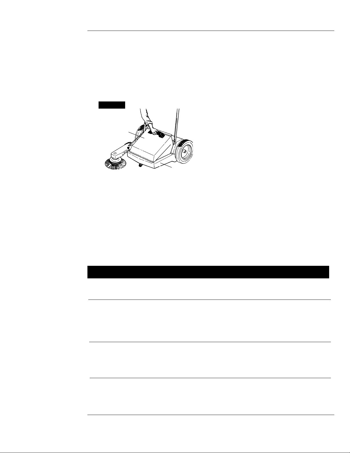
EMPTYING DIRT HOPPER
1. To empty the dirt hopper, lift up on the handle
located on the front of the hopper, and empty
contents into a proper container.
2. Replace dirt hopper back on sweeper by placing
front edge of hopper on sweeper frame.
3. Apply downward pressure until the hopper is in its
proper position.
4.The dirt hopper should be emptied after each use,
or as required. A full dirt hopper will affect the
sweeping efficiency of the push sweeper.
Maintenance
1. After each use, check for materials which may
have become wrapped around brushes or wheels,
and remove immediately.
2. Do not lubricate gears, clutch or other internal
parts.
3. Inspect rubber dust seals periodically for wear or
damage; replace as required.
4. Inspect the main broom periodically for wear;
replace when the bristles are worn to a length of
1
1
/2inches or less. The main broom can be easily
replaced by removing three screws from each half.
The same screws can then be used to attach the
replacement broom.
5. Side broom should be inspected periodically for
wear; replace when (with the adjustment in the
down position) less than
1
/3of the bristles come in
contact with the surface. The side broom can be
easily replaced by removing the screws from the
brush holder and reassembling the replacement
brush, using the same hardware.
4
Sweeper
Frame
▲
▲
Dirt
Hopper
- Emptying Procedure
Figure 7
Page 5

5
ITEM DESCRIPTION PART NO. Qty.
(*) Standard hardware item, available locally.
20
35
10
19
6
1
▲
▲
▲
▲
33
28
▲
18
▲
▲
▲
14
▲
31
▲
32
▲
8
▲
▲
38
▲
3
▲
2
▲
11
▲
21
▲
15
▲
25
▲
13
▲
4
▲
16
▲
9
▲
12
▲
5
▲
24
▲
6
▲
16
▲
6
▲
17
▲
29
▲
22
30
▲
32
27 26
▲
▲
▲
23
▲
41
▲
39
▲
16
▲
40
▲
36
▲
37
▲
16
▲
45
▲
4
▲
42
▲
43
▲
44
▲
42
▲
34
▲
7
▲
20
▲
▲
46
▲
13
7
▲
▲
STANDARD ACCESSORIES
Wide 19" (48.26 cm) Main broom
13" Diameter (33.02 cm) Side broom
8 Gallon (30.28 liters) Large capacity hopper
1 Upper Handle 56038923 1
2
1
/4- 20 x 11/4”
Slotted truss head screw * 4
3 Lower handle 56038924 1
4
1
/4” - 20 Hex nut * 6
5
1
/4”, External tool lockwasher * 4
6
1
/4” x 1” Philips * 6
truss head screw (type BT)
7 Height adjustment nut (half) 56038925 2
8 Seal - hopper 56038926 1
9
5
/16- 18 x 41/2” Round head bolt * 2
10
5
/16- 18 x 51/2” Round * 2
head bolt (square neck)
11 Rear housing 56038927 1
12 Main broom adjustment knob 56038928 1
13
3
/8” Flatwasher * 2
14 Set screw collar 56038929 1
15 #10 x 1” Slotted hex * 2
head screw (type BF)
16 #10 x
3
/4” Phillips pan head * 15
screw (type AB)
17 Rear floor seal 56038930 1
18 Rear seal support rod 56038931 1
19 Axle 56038932 1
20 Pivot hub 56038933 2
21 Wheel and bearing assembly 56038934 1
includes 1 wheel
and 2 bearings
22 Wheel and clutch assembly 56038935 1
23 Retaining ring 56038936 2
24 Hopper handle 56038937 1
25 Hopper 56038938 1
26 Floor blade 56038939 1
27 Floor blade retainer 56038940 1
28 Wheel bearing 56038941 4
29
1
/2”, Flatwasher * 8
30 External E-ring 56038942 1
31 Brush shaft assembly 56038943 1
32 Main broom (half) 56038944 2
33 Bearing 56038945 1
34 O-ring 56038946 1
35 1
3
/4” x #10 Phillips pan * 6
head screw (Type A)
36 Serrated hex flange nut,
5
/16”*4
37 Floor seal (sides) 56038947 2
38 Main frame 56038948 1
39 Caster socket 56038949 1
40 Caster support 56038950 1
41 Caster 56038951 1
42
1
/4 x 11/2” Hex head * 6
screw (type AB)
43
1
/4 - 20 x 13/4” Round head * 2
bolt (square neck)
44 Inner sidearm 56038952 1
mounting bracket
45 Outer sidearm 56038953 1
mounting bracket
46 Lockwasher * 2
Page 6

6
▲
20
▲
26
▲
19
▲
16
▲
18
▲
12
▲
11
▲
15
▲
14
▲
13
▲
11
▲
10
▲
9
▲
8
▲
7
▲
6
▲
12
▲
23
▲
24
▲
23
▲
25
▲
22
▲
2
▲
1
▲
5
▲
17
▲
21
▲
19
▲
2
1
▲
4
▲
3
▲
21
▲
(*) Standard hardware item, available locally.
(**) Item obsolete, replaced by 56038958.
Adjusting Side Broom Arm
ITEM DESCRIPTION PART NO. Qty.
1 Hairpin 56038954 2
2 Clevis pin 56038955 2
3
1
/4” - 20 hex nut * 2
4 Stop adjustment knob 56038956 1
5
3
/8-16 x 4” Round head * 1
bolt, (square neck)
6
3
/8” Threaded insert ** 1
7 Stop adjustment foot 56038959 1
8 Side broom arm 56038958 1
9
1
/2” Flat washer * 1
10 Side broom shaft 56038960 1
11 O-ring 56038946 2
12 Bearing 56038945 2
13 Side broom cover 56038961 1
143/8” Lockwasher * 1
153/8” - 16 Hex nut * 1
16 Side broom bumper 56038962 1
17 Side broom 56038963 1
181/4” Flatwasher * 3
191/4” Lockwasher * 3
201/4x 1” Slotted pan head * 3
screw (type AB)
21 Sidearm bracket 56038964 2
221/4- 20 x 3” Round head * 2
square neck bolt
23 Belt guide 56038965 4
24 Spacer 56038966 2
251/4x 11/2” Hex head screw * 2
(type AB)
26 Belt 56038967 1
Page 7

7
Lea y guarde estas instrucciones. Lea detenidamente antes de intentar ensamblar, instalar, operar o realizar el mantenimiento
de los productos. Protéjase a usted mismo y a los demás, observando toda la información sobre seguridad. Cualquier error en
el cumplimiento de las instrucciones puede provocar lesiones personales y/o daños de propiedad. Conserve las instrucciones
para futuras referencias.
Uso Comercial / Industrial
Especificaciones
8 Gal. 48,26 cm 33,02 cm 25,4 cm 68,58 cm 45 Lbs.
(30,28 litros) (19”) de (13”) de (10”) (27”) (20,4 kg)
Ancho Diámetro Semi-nuemáticos
No corredizos
Escobilla Escobilla Ruedas Anchura de
Capacidad principal latéral principales barrido Peso
Descripción
La barredora de empuje está diseñada como un sitema de ahorro de tiempo para la limpieza de a´reas
grandes. La barredora de empuje se maniobra fácilmente y limpia un área de 27” (68,58 cm). Cuenta con un
armazón de estructura durable, una tolva de gran capacidad, un semi-neumático de 10” (25,4 cm), ruedas no
corredizas, escobilla lateral para limpiar a lo largo de las paredes, orillas y debajo de anaqueles o estantes, y
una escobilla de altura ajustable para diferentes usos y superficies.
INSTRUCCIONES
IMPORTANTES DE
SEGURIDAD
Desempaque
1. La barredora de empuj vien ya parcialmente
ensamblada. Antes de hacerla funcionar, una el
manubrio y la escobilla lateral al bastidor principal de
la unidad.
2. Desempaque la barredora de la caja y colóquela en
una superficie plana.
3. Quite la tolva para la basura del armazón del a
barrdora.
4. Quite las partes que puedan venir empacadas en la
tolva.
5. Antes de desechar la caja, asegúrese de que todas
las partes sueltas y los folletos hayan sido
desempacados.
Para reducir el
riesgo de fuego o
lesiones personales:
1. No aspire materiales tóxicos, carcinógenos,
combustibles u otros que puedan ser dañinos tales
como asbesto, arsénico, bario, berilio, plomo,
pesticidas y otros que puedan poner en peligro su
salud.
2. No aspire cigarros encendidos u otros materiales
humentes como cenizas, cerillos o algo similar.
3. Para evitar lesiones personales, use guantes
gruesos cuando quite vidrio, metal u otros
materiales filosos de la tolva.
4. La tolva deberá ser vaciada después de cada uso.
5. Está barredora no está diseñada para usarse con
líquidos.
6. No lo exponga a la lluvia. Almacénelo en el interior.
7. No permita que sea usado como juguete. Es
necesaria una estricta atención cuando es utilizada
por niños o cerca de estos.
8. El functionamiento de una barredora tradicional
puede provocar que algunas sustancias ajenas
penetren en sus ojos. Siempre utilice lentes
protectores cuando esté operando su barredora.
9. ESTÉ ALERTA. Observe lo que está haciendo y
use su sentido común. No use su barredora de
empuje cuando esté cansado, distraído o bajo la
influencia de alguna droga, alcohol o medicamento
que pueda disminuir el control.
Ensamblaje
ENSAMBLAJE DEL MANUBRIO
1. Coloque los extremos del manubrio inferior en los
agujeros del armazón de la barredora. Ünalos con
los tornillos. (vea la Figura 1).
2. Una el manubrio superior al inferior usando tornillos
para metales, arandelas de seguridad y tuercas (vea
la Figura 2).
SIEMPRE UTILICE
PROTECCION
PARA LOS OJOS
Modelo: 56100874
!ADVERTENCIA
Page 8

8
3. La agarradera de la tolva deberá instalarse a ésta
con los tornillos suministrados (vea la Figura 3).
ENSAMBLAJE DE LA ESCOBILLA
LATERAL
Refiérase a la Figura 4
1. La banda de transmisión deberá colocarse en la polea
cuando hya sido recibida. Verifique que la banda esté
vien colocada en la polea y entre las guías.
2. Con el brazo lateral colocado como se muestra en la
Figura 4, ponga la banda entre las paredes del brazo de
la escobilla lateral. Coloque la banda de arrastre
exterior sobre la rueda trasera y encima de la ménsula
de montaje. La banda de arratre interna deberá ir
DEBAJO de la ménsula de montaje.
3. Una el brazo de la escobilla lateral, alineándo los
agujeros del brazo con los de la ménsula de montaje.
Inserte los pasadores de horquilla y asegúreslos con las
abrazaderas de horquilla.
4. Coloque el amortifuador de choque de la escobilla al
lado de la polea con el reborde externo vieno hacia la
escobilla lateral. Úna ésta a la polea con los tornillos,
las arandelas de seguridad y las roldanas.
5. Baje el brazo de la escobilla lateral y vuelva a colocar la
tolva.
6. En caso de que la escobilla gire en la dirección
equivocada, significa quer la banda no está instalada
correctamente.
Operación
ESCOBILLA PRINCIPAL
Refiérase a la Figura 5.
1. La escobilla principal ha sido preinstalada en la fábrica
para una máxima eficiencia al barrer.
2. En caso de que sean necesarios ajustes para distintas
superficies y usos, podrán hacerse girando la perilla
ajustadora. El indicador de la altura mostrará la
posición de la escobilla conforme realice su ajuste.
(vea la Figura 5)
3. Para un mejor funcionamiento durante la operación, las
cerdas de la escobilla deberán tocar apenas el suelo.
NOTA: Si la escobilla principal está colocada muy abajo,
la barredora será muy difícil de empujar.
ESCOBILLA LATERAL
Refiérase a la Figura 6
1. Esta escobilla deberá ser bajada y usada cuando se
barra a lo largo de paredes u orillas; también puede ser
usada cuando se barran áreas abiertas.
2. La altura de la escobilla lateral deberá ser ajustada de
manera que aproximadamente
1
/3de las cerdas estén
tocando el suelo. El ajuste puede ser hecho girando la
perilla ajustadora.
OPERANDO SU BARREDORA DE EMPUJE
Empuje la barredora hacia adelante a una velocidad de
caminado normal; ésta no funciona cuando se jala hacia
atrás.
VACIANDO LA TOLVA
1. Para vaciar la tolva, levante la agarradera localizada en
la parte frontal de ésta y vacíe el contenido en un
contenedor adecuado.
2. Vuelva a colocar la tolva en su lugar, poníendo el
borde frontal de ésta en el armazón de la barredora.
3. Aplique presión hasta que la tolva quede en su
posición correcta.
▲
Tolva de la
Barredora
▲
Figura 3
Figura 1
Figura 2
Manubrio
Inferior
▲
Manubrio
Inferior
▲
Manubrio
Superior
Agarradera
de la Tolva
▲
Escobilla
Lateral
▲
▲
▲
Banda de
Arreastre
Externa
▲
Amortiguador
de Cjoque de
la Escobilla
▲
Banda de Arrastre Interna
▲
Guías de la
Banda
▲
Ménsula de
Montaje
▲
▲
- Ajuste de la escobilla Lateral
▲
▲
Brazo de la Escobilla Lateral
Brazo
de la
Escobilla
Lateral
▲
Barredora
Brazo de
la Polea
Polea
de la
Escobilla
Abrazadera
de Horquilla
▲
Pasador de
Horquilla
Figura 6
BAJA
ALTA
COLOCACIÓN
DE LA ESCOBILLA
GIRE PARA AJUSTAR
- Ajuste de la
Escobilla Principal
Figura 5
Figura 4
Page 9

9
La Barredora es muy 1. La Escobilla lateral está 1. Ajuste la escobilla lateral
difícil de empujar colocada muy abajo
2. La escobilla principal está 2. Ajuste la escobilla
colocada muy abajo principal
3. Un objeto grande ha sido 3. Quite el objeto
atrapado.
Aspiración Pobre 1. Alguna cuerda o cualquier 1. Quite la cuerda o el
otro objeto extraño está extraño
atorado o enrollado en la
escobilla principal
2. La Tolva está saturada 2. Vacíe la Tolva
3. La escobilla principal está 3. Ajuste la escobilla
colocada muy alta principal
4. La escobilla lateral está 4. Ajuste la escobilla lateral
colocada muy alta
Polvo en Exceso 1. La Tolva está saturada 1. Vacíe la Tolva
durante la Operación
2. Alguna fuga en el sello de piso 2. Reemplace el sello dañado
3. La manera de caminar 3. Disminuya la velocidad y
al barrer es muy rápida levante el brazo lateral en
caso de limpiar grandes
áreas abiertas a una mayor
velocidad
Rayas o Parches Algún tipo de línea de mugre Limpie cualquier línea
dejadas por la puede formarse en el bastidor formada en el bastidor
bareredora detrás de la escobilla principal principal.
Reparación de Desperfectos
Desperfecto Posible(s) Causa(s) Solución
4. La Tolva deberá vaciarse después de cada uso, o
conforme se requiera. Una tolva saturada podría
afectar la eficiencia en el funcionamiento de su
barredora.
Mantenimiento
1. Después de cada uso, revise las cerdas y las ruedas
por los posibles materiales que hayan quedado
atrapados en éstas, y quítelos inmediatamente.
2. No lubrique los engranes, el embrague ni cualquier otro
componente interno.
3. Revise periódicamente los sellos de goma para el
polvo, en caso de que estén dañados o muy usados,
reemplácelos.
4. Revise periódicamente la escobilla principal,
reemplácela cuando las cerdas estén desgastadas o
con una longitud menor a 1
1
/2pulgada. La escobilla
principlal puede ser fácilmente reemplazada quitando
los tres tornillos de cada mitad. Estos mismos tornillo
pueden ser usados para instalar la escobilla de
reemplazo.
5. Revise la escobilla lateral periódicamente; reemplácela
cuando menos de
1
/3de las cerdas hagan contacto con
la superficie (con el ajuste en la posición de BAJA
(LOW)). La escobilla lateral puede ser fácilmente
reemplazada quitando los tornillos del soporte de la
esobilla y volviéndo a ensamblar la de reemplazo, use
los mismos tornillos.
Armazón de la
Bareredora
▲
▲
Tolva Vacía
- Procedimiento de Vaciado
Figura 7
Page 10

Notes
Page 11

Nilfisk-Advance, Inc.
14600 21st Avenue North
Plymouth, MN, 55447-3408
www.nilfisk-advance.com
Phone: 800-989-2235
Fax: 800-989-6566
©2000 Nilfisk-Advance, Inc.,
Plymouth, MN 55447-3408
Printed in the U.S.A.
 Loading...