

Page 1
OPERATOR
M A N U A L
Kent
SelectScrub 17
Model 56302300
3/99 Form Number 56041433
Page 2
A
13
10
11
19
14
12
15
1
2
3
16
4
5
6
20
9
21
22
Cautions and Warnings............................................. 4
Introduction ............................................................... 6
Know Your Machine .................................................. 6
Prepare the Machine For Use ................................... 6
Machine Operation.................................................... 7
After Use ................................................................... 7
Maintenance Schedule.............................................. 8
Charging the Batteries .............................................. 8
Squeegee Cartridge Rotation.................................... 8
Battery Condition Indicator........................................ 9
Troubleshooting ........................................................ 9
Technical Specifications............................................ 9
18
7
8
17
23
24
2 - FORM NO. 56041433 / SELECTSCRUB 17
Page 3
B
FRONT
C
D
19
FORM NO. 56041433 / SELECTSCRUB 17 - 3
Page 4

CAUTIONS AND WARNINGS
SYMBOLS
Kent uses the symbols below to signal potentially dangerous conditions. Read this information carefully and take the necessary
steps to protect personnel and property.
DANGER!
Is used to warn of immediate hazards that will cause severe personal injury or death.
WARNING!
Is used to call attention to a situation that could cause severe personal injury.
CAUTION!
Is used to call attention to a situation that could cause minor personal injury or damage to the machine or other property.
GENERAL SAFETY INSTRUCTIONS
Specific Cautions and Warnings are included to warn you of potential danger of machine damage or bodily harm.
WARNING!
* This machine should only be used by properly trained and authorized persons.
* Keep sparks, flame and smoking materials away from batteries. Explosive gases are vented during normal operation.
* Charging the batteries produces highly explosive hydrogen gas. Charge batteries only in well-ventilated areas, away from
open flame. Do not smoke while charging the batteries.
* Remove all jewelry when working near electrical components.
* Disconnect the batteries before servicing electrical components.
* Never work under a machine without safety blocks or stands to support the machine.
* Do not dispense flammable cleaning agents, operate the machine on or near these agents, or operate in areas where
flammable liquids exist.
* Do not clean this machine with a pressure washer.
* Do not operate this machine on ramps or inclines of more than a 2 percent gradient.
CAUTION!
* This machine is not approved for use on public paths or roads.
* This machine is not suitable for picking up hazardous dust.
* When operating this machine, ensure that third parties, particularly children, are not endangered.
* Before performing any service function, carefully read all instructions pertaining to that function.
* Disconnect the battery connector/ charger plug before changing the brushes, and before opening any access panels.
* Take precautions to prevent hair, jewelry, or loose clothing from becoming caught in moving parts.
* Use caution when moving this machine in below freezing temperature conditions. Any water in the solution or recovery
tanks or in the hose lines could freeze.
SAVE THESE INSTRUCTIONS
4 - FORM NO. 56041433 / SELECTSCRUB 17
Page 5

CONSIGNES DE SÉCURITÉ
SYMBOLES
Les symboles ci-dessous sont utilisés pour signaler des conditions d’emploi qui présentent un danger. Lisez ces informations
avec soin et prenez les mesures nécessaires de protection des personnes et des biens.
DANGER!
avertit de dangers immédiats causant des blessures graves ou la mort.
ATTENTION!
attire l’attention sur une situation pouvant causer des blessures graves aux personnes.
PRÉCAUTIONS D’EMPLOI!
attire l’attention sur une situation pouvant causer des blessures légères ou des dommages à la machine ou à d’autres biens.
CONSIGNES GÉNÉRALES DE SÉCURITÉ
Précautions d’emploi et recommandations spécifiques, vous avertissent des dangers possibles d’endommagement de la machine
ou de dommages corporels.
ATTENTION!
* Cette machine ne devra être utilisée que par des personnes dûement formées et autorisées.
* Tenez les étincelles, flammes et matériaux incandescents éloignés des batteries. Des gaz explosifs sont ventilés pendant
un fonctionnement normal.
* Le chargement des batteries produit du gaz hydrogène extrêmement explosif. Chargez les batteries uniquement dans
des zones bien aérées, loin de toute flamme. Ne fumez pas lors du chargement des batteries.
* Retirez tout bijou lorsque vous travaillez près des composants électriques.
* Déconnectez les batteries avant l´entretien des composants électriques.
* Ne travaillez jamais sous une machine sans cales de sécurité ou une plateforme pour porter la machine.
* N´utilisez pas d´agents nettoyants inflammables, n´utilisez pas la machine sur ou près de ces agents, ou ne l´utilisez pas
dans des zones où ces liquides inflammables existent.
* Ne nettoyez pas cette machine avec un jet à haute pression.
* N´utilisez pas cette machine sur des rampes ou plans inclinés de plus de 2 pour cent d´inclinaison.
PRÉCAUTIONS D’EMPLOI!
* Cette machine n´est pas concue pour une utilisation sur des voies publiques.
* Cette machine n´est pas appropriée au ramassage de poussière dangereuse.
* Lors de l´utilisation de cette machine, assurez-vous que des tiers, particulièrement des enfants, ne soient pas en danger.
* Avant d´effectuer toute maintenance, lisez attentivement toutes les instructions se rapportant à cette opération.
* Débranchez la prise de raccord / charge de la batterie avant de changer les brosses, et avant d´ouvrir tout panneau
d´accès.
* Prenez les précautions nécessaires pour éviter que les cheveux, bijoux et vêtements amples ne soient pris dans les parties
mobiles.
* Faites preuve de prudence lorsque vous déplacez la machine dans des conditions atmosphériques inférieures à 0 degré.
L´eau se trouvant dans les réservoirs de solution ou de récupération ou dans les tuyaux pourrait geler.
CONSERVER CES INSTRUCTIONS
FORM NO. 56041433 / SELECTSCRUB 17 - 5
Page 6

INTRODUCTION
This manual will help you get the most from your Kent SelectScrub 17. Read
it thoroughly before operating the machine.
Note: Bold numbers in parentheses indicate an item illustrated on page
2 (Figure A).
This product is intended for commercial use only.
PARTS AND SERVICE
Repairs, when required, should be performed by your Authorized Kent Service
Center, who employs factory trained service personnel, and maintains an
inventory of Kent original replacement parts and accessories.
Call the KENT DEALER named below for repair parts or service. Please
specify the Model and Serial Number when discussing your machine.
(Dealer, affix service sticker here.)
PREPARE THE MACHINE FOR USE
B - INSTALLING THE BATTERIES
WARNING!
Use extreme caution when working with batteries. Sulfuric acid
in batteries can cause severe injury if allowed to contact the skin
or eyes. Explosive hydrogen gas is vented from the batteries
through openings in the battery caps. This gas can be ignited
by any electrical arc, spark or flame.
When Servicing Batteries...
* Remove all jewelry
* Do not smoke
* Wear safety glasses
* Work in a well-ventilated area
* Do not allow tools to touch more than one battery terminal at a time
NAME PLATE
The Model and Serial Number of your machine are shown on the Nameplate
on the machine. This information is needed when ordering repair parts for the
machine. Use the space below to note the Model and Serial Number of your
machine for future reference.
MODEL
SERIAL NUMBER
UNCRATING
When the machine is delivered, carefully inspect the shipping carton and the
machine for damage. If damage is evident, save the shipping carton so that
it can be inspected. Contact the Kent Customer Service Department immediately to file a freight damage claim.
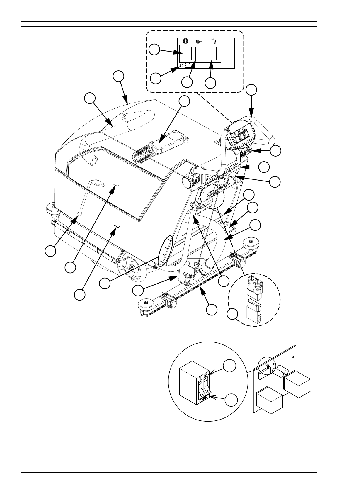
A - KNOW YOUR MACHINE
1 Operator Handle Tube
2 Handle Height Adjustment Knob
3 Squeegee Raise / Lower Handle
4 Battery Tray
5 Brush Raise / Lower Pedal
6 Squeegee Hose
7 Solution Tank Drain Hose
8 Squeegee Assembly
9 Recovery Tank
10 Recovery Tank Drain Hose
11 Solution / Recovery Tank Cover
12 Recovery Tank Automatic Float Shut Off
13 Brush Switch
14 Vacuum Switch
15 Solution Switch
16 Solution Flow Control Lever
17 Battery Connector / Charger Plug
18 Squeegee Mount
19 Battery Condition Indicator
20 Kick Stand
21 Solution Level Indicator
22 Solution Tank
23 Low Voltage Cutout (STD Position)
24 Low Voltage Cutout (MF Position)
CAUTION!
Electrical components in this machine can be severely damaged if the batteries are not installed and connected properly.
Batteries should be installed by Kent, a qualified electrician, or
the battery manufacturer.
1 Remove the batteries from their shipping crate and carefully inspect
them for cracks or other damage. If damage is evident, contact the
carrier that delivered them or the battery manufacturer to file a damage
claim.
2 Disconnect the Battery Connector / Charger Plug (17).
3 Remove the battery cables from inside the tank. Tip the Solution /
Recovery Tank Cover (11) back until the prop rod catches and then tip
the Recovery Tank (9) forward.
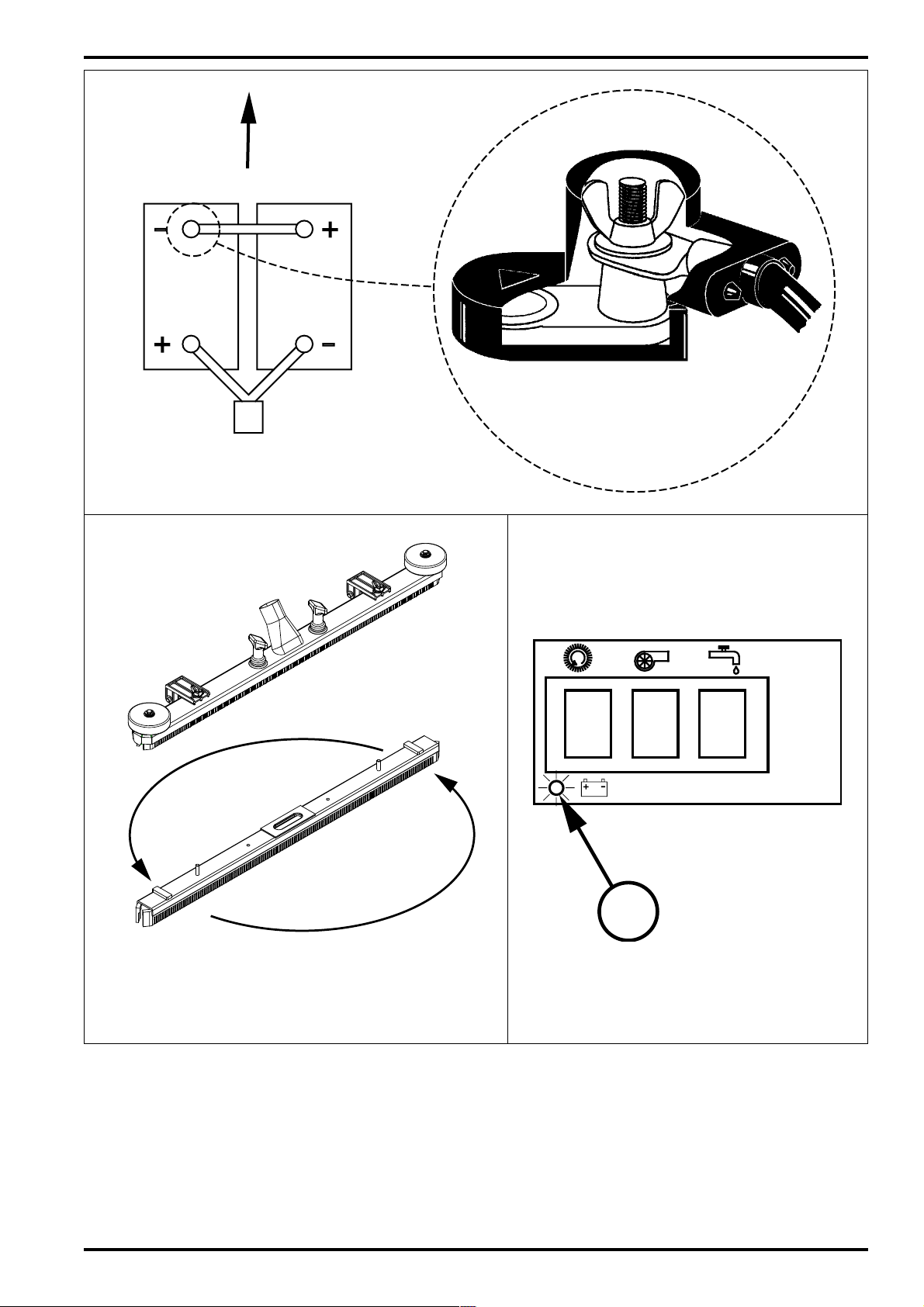
4 Your machine comes from the factory with enough battery cables to
install two 12 volt, 105 amp hour batteries. Carefully lift the batteries
into the battery compartment and arrange them exactly as shown on
page 3 (Figure B).
5 Install the battery terminal covers provided with the machine as shown.
6 Install the battery cables as shown, make sure that the red cable from
the charger plug is connected to the positive terminal and the black
cable connected to the negative terminal. Position the cables so the
battery caps can be easily removed for battery service.
7 Carefully tighten the wing nut on each battery terminal until the terminal
will not turn on the battery post. Do not over-tighten the terminals, or
they will be very difficult to remove for future service.
8 Coat the terminals and posts with grease, petroleum jelly, or spray-on
battery terminal coating (available at most auto parts stores).
9 Connect the Battery Connector / Charger Plug (17).
LOW VOLTAGE CUTOUT SELECTION
The SELECTSCRUB 17 is equipped with a low voltage cutout feature to
prevent over-discharging the batteries. Standard wet cell batteries (flooded
electrolyte) allow for the greatest amount of machine run time due to lower
cutout voltage. If maintenance free batteries (gelled electrolyte) are used, the
low voltage cutout can be set to prevent the over-discharge of the batteries.
The low voltage cutout has two settings, set the first white switch to STD or
position (23) for standard batteries and MF or position (24) for maintenance
free batteries. The selector switch is on the circuit board, which is located
behind the control panel.
6 - FORM NO. 56041433 / SELECTSCRUB 17
Page 7

INSTALLING THE BRUSH OR PAD HOLDER
WARNING!
Moving parts - turn the Solution Switch (15), Brush Switch (13)
and Vac Switch (14) OFF and disconnect the Battery Connector
/ Charger Plug (17) before servicing.
IMPORTANT!
Empty the solution and recovery tank before tipping the machine
back to install or change a brush, or to install or turn over a pad.
1 If using a pad, install the pad on the pad holder.
2 Make sure the brush drive motor is in the raised position.
3 Remove the Squeegee Assembly (8), tip the machine back and flip
down the Kick Stand (20) at the front of the machine. Use the Kick Stand
(20) to hold the machine up while installing the brush or pad holder.
4 Align the slots on the brush or pad holder with the lugs on the drive hub.
5 Turn the brush or pad holder counter-clockwise (to the left) until it locks
into place.
6 Latch the Kick Stand (20) back into place and tip the machine back
forward. Re-install the Squeegee Assembly (8).
INSTALL THE SQUEEGEE
1 Install the Squeegee Assembly (8) onto the Squeegee Mount (18) as
shown on page 1 (Figure A). Tighten the thumb nuts securely.
2 Attach the Squeegee Hose (6) to the Squeegee Assembly (8) as shown.
FILLING THE SOLUTION TANK
Fill the solution tank with a maximum of 23 liters (6 gallons) of cleaning solution.
Do not fill the solution tank above 8 cm (3 inches) from the top of the tank. The
solution should be a mixture of water and the proper cleaning chemical for the
job. Always follow the dilution instructions on the chemical container label. The
amount of solution in the Solution Tank can be determined at-a-glance with the
Solution Level Indicator (21). Line up the solution level in the clear Solution
Tank Drain Hose (7) with the marks (21) on the side of the Solution Tank (22).
The top mark indicates a full tank or 23 litres (6 gallons) and each mark under
that indicates a drop of 5.75 litres (1-1/2 gallons) or 1/4 tank.
CAUTION!
Use only low-foaming, non-flammable liquid detergents intended
for machine application.
MACHINE OPERATION - WET SCRUBBING
Note: Bold numbers in parentheses indicate an item illustrated on page
2 (Figure A).
1 Move Squeegee Raise / Lower Handle (3) down to lower the squeegee
assembly.
2 Lower the Brush Raise / Lower Pedal (5) by pushing the foot pedal down
and to the right.
3 Position the Solution Flow Control Lever (16) at its mid range.
4 Turn the Brush Switch (13), Vac Switch (14) and Solution Switch (15)
ON. The solution will not come ON unless the Brush Switch (13) is ON.
5 Grip the Operator Handle Tube (1) and push the machine forward to
scrub at a slow walking speed for best results.
CAUTION!
To avoid damaging the floor, keep the machine moving while
the brush is turning.
6 Re-adjust the Solution Flow Control Lever (16) so a thin , even layer
of solution can be seen in front of the Squeegee Assembly (8).
7 The Recovery Tank (9) has an Automatic Float Shut-Off (12) to block
the vacuum system when the recovery tank is full. You can tell when
the float closes by the sudden change in the sound of the vacuum
motor. When the float closes, the recovery tank must be emptied. The
machine will not pickup water with the float closed.
8 When the Recovery Tank (9) is full, turn the Solution Switch (15), Brush
Switch (13) and Vac Switch (14) OFF and raise the Squeegee
Assembly (8) and Brush (5). When the Brush Switch (13) is turned OFF
the solution valve will also automatically shut off. Move the machine
to a designated “DISPOSAL SITE”.
NOTE: The brush motor WILL NOT shut off when the brush is raised
off the floor, so make sure you turn the Brush Switch (13) OFF before
raising the brush.
9 To empty the Recovery Tank (9) open the Solution / Recovery Tank
Cover (11) until the prop rod catches and direct the Recovery Tank
Drain Hose (10) to a designated “DISPOSAL SITE” and remove the
plug.
WET VACUUMING
Fit the machine with optional attachments for wet vacuuming.
1 Disconnect the Squeegee Hose (6) from the Squeegee Assembly (8).
2 Install a 3.8 cm (1-1/2” ) dia. hose coupler into the end of the Squeegee
Hose (6).
3 Attach a 3.8 cm (1-1/2” ) dia. vacuum hose to the coupler. Then attach
a two bend wand and squeegee floor tool to the hose.
4 Turn the Vacuum Switch (14) ON.
AFTER USE
1 Turn the Solution Switch (15), Brush Switch (13) and Vac Switch (14)
OFF.
2 Raise the brush (or pad) and raise the squeegee. Move the machine
to a designated “DISPOSAL SITE”.
3 To empty the solution tank, take the Solution Tank Drain Hose (7) off
its Barbed Elbow Connector. Direct the hose to a designated “DISPOSAL SITE”. Rinse the tank with clean water. Inspect the solution
hoses; replace if kinked or damaged.
4 To empty the recovery tank, open the Solution / Recovery Tank Cover
(11) until the prop rod catches and take out the Recovery Tank Drain
Hose (10). Direct the hose to a designated “DISPOSAL SITE” and
remove the plug. Rinse the tank with clean water. Inspect the recovery
and vacuum hoses; replace if kinked or damaged, clean out if clogged.
Also inspect the recovery tank cover gasket.
5 Remove the brush or pad holder. Rinse the brush or pad with warm
water and hang it up to dry. Allow buffing pads to dry completely before
using again.
6 Remove the squeegee, rinse it with warm water and hang it up to dry.
7 Check the maintenance schedule and perform any required mainte-
nance before storage.
FORM NO. 56041433 / SELECTSCRUB 17 - 7
Page 8

MAINTENANCE SCHEDULE
Maintenance Item Daily Weekly Monthly Yearly
Clean the Recovery Tank X
Clean the Float Screen X
Clean the Solution Tank & Screen X
Clean the Squeegee X
Inspect Tanks and Hoses X
Charge the Batteries X
Check Battery Water Level X
Lubrication X
*Check Vacuum Motor Brushes X
*Have Kent check the carbon motor brushes once a year or after 300 operating
hours.
8 Store the machine in a clean, dry place.
CHARGING THE BATTERIES
Charge the batteries when the Battery Condition Indicator (19) is flashing RED.
CAUTION!
Do not allow the batteries to sit in a discharged condition. Doing
so will greatly reduce battery life.
WARNING!
Do not fill the batteries with water before charging.
Charge batteries in a well-ventilated area.
Do not smoke while servicing the batteries.
Disconnect the batteries. Push the connector from the charger into the Battery
Connector / Charger Plug (17) on the batteries. Follow the instructions on the
battery charger.
CAUTION!
To avoid damage to floor surfaces, wipe water and acid from the
top of the batteries after charging.
CHECKING THE BATTERY WATER LEVEL
Check the water level of the batteries at least once a week.
After charging the batteries, remove the vent caps and check the water level
in each battery cell. Use distilled water in a battery filling dispenser (available
at most auto parts stores) to fill each cell to the level indicator (or to 10 mm (3/
8”) over the top of the separators). DO NOT over-fill the batteries!
CAUTION!
Acid can spill onto the floor if the batteries are overfilled.
Tighten the vent caps. Wash the tops of the batteries with a solution of baking
soda and water (2 tablespoons of baking soda to 1 liter / 1 quart of water).
LUBRICATING THE MACHINE
Once a month, apply oil to lubricate the:
• Front Swivel Casters
• Squeegee Pivot Points
• Brush Lift Linkage
• Rear Wheel Bearings
• Solution Valve Linkage
• Kick Stand
VACUUM MOTOR BRUSHES
Have Kent check the carbon motor brushes once a year or after 300 operating
hours.
IMPORTANT !
Motor damage from failure to service the carbon brushes is not
covered under warranty.
C - SQUEEGEE CARTRIDGE ROTATION OR REPLACEMENT
If the squeegee leaves narrow streaks of water, it is probably dirty or
damaged. Remove the squeegee, rinse it under warm water and inspect the
squeegee blades. Rotate the squeegee cartridge if the rear blade is cut, torn,
or worn to a radius. Replace the squeegee cartridge if both blades are cut,
torn, or worn to a radius.
To Rotate the Squeegee Cartridge...
1 Raise the Squeegee Assembly (8).
2 Remove the Squeegee Assembly (8) from the machine.
3 Remove the squeegee cartridge from the Squeegee and rotate it as
shown (or replace if both blades are severely worn or torn).
4 Reinstall the cartridge into the Squeegee Assembly (8) and the
Squeegee Assembly (8) onto the machine.
NOTE: The Squeegee Assembly (8) is not adjustable.
8 - FORM NO. 56041433 / SELECTSCRUB 17
Page 9

D - BATTERY CONDITION INDICATOR OPERATION
To operate, the Brush Switch (13) or the Vac Switch (14) must be turned on to
activate the Battery Condition Indicator (19) to determine the charge condition
of the battery pack.
Listed below is the explanation of the Battery Condition Indicator (19) light
functions:
1 Flashing Red Light: Condition of battery 95% to 99% discharged.
2 Constant Red Light: 100% discharged.*
*NOTE: When the indicator glows steady RED, the operator will have 2
minutes of run time left (for batteries in good condition). The brush motor will
automatically shut off and the vac motor will continue to run for 10 minutes to
pick up any solution left on the floor.
Additional Note: If at any time during machine operation the battery system
voltage drops below 19 volts, the brush and vac motors will immediately shut
off. The red light will also glow steady to indicate a low voltage fault condition.
Check condition of batteries and recharge them.
If an overload occurs, determine and correct the cause of the overload. The
machine has an internal electronic circuit breaker built into the control board.
To reset the electronic circuit breaker, turn the switch for the affected device
off and then back on.
TROUBLESHOOTING
POOR WATER PICKUP
1 Recovery tank full, float shut-off closed
2 Blocked vacuum system (squeegee hose and float cage)
3 Disconnected or damaged vacuum hoses
4 Blades worn or damaged
5 Recovery tank cover not seated properly
6 Recovery tank cover gasket damaged
SQUEEGEE STREAKS
1 Debris under the squeegee blade
2 Worn, nicked or torn squeegee blade
3 Debris build up on the squeegee blade
SWIRL MARKS
1 Running the machine with a dry brush or pad (no cleaning solution)
2 Incorrect brush or pad for the application
3 Debris caught in brush (or pad)
TECHNICAL SPECIFICATIONS
Model SELECTSCRUB 17
Model No. 56302300
Current A 40
Voltage, batteries V 24V/2 x 12V
Battery capacity Ah 105
Protection grade IP23
Sound pressure level as per ISO3744 (at operator position) dB (A)/20µPa 71
Total weight (with full sol. tank and batteries) lbs / kg 376 / 171
Net weight (with empty tanks and no batteries) lbs / kg 157 / 71
Vibrations at the Hand Controls m/s
2
<2.5m/s
2
FORM NO. 56041433 / SELECTSCRUB 17 - 9
Page 10

Nilfisk-Advance, Inc.
14600 21st Avenue North
Plymouth, MN, 55447-3408
www.nilfisk-advance.com
Phone: 800-989-2235
Fax: 800-989-6566
©2000 Nilfisk-Advance, Inc.,
Plymouth, MN 55447-3408
Printed in the U.S.A.
 Loading...