


http://biz.lgservice.com
Window Air Conditioner
SVC MANUAL(General)
MODEL : Window
CAUTION
Before Servicing the unit, read the safety precautions in General SVC manual. Only for authorized service personnel.

Air Conditioner Service Manual
CONTENTS
Safety Precautions ........................................................................................................................... |
3 |
Operation .......................................................................................................................................... |
6 |
Features ....................................................................................................................................... |
6 |
Control Locations Function of Controls ........................................................................................ |
6 |
Troubleshooting Guide..................................................................................................................... |
9 |
Piping System .............................................................................................................................. |
9 |
Troubleshooting Guide................................................................................................................ |
10 |
Electrical Parts Troubleshooting Guide....................................................................................... |
12 |
Room Air Conditioner Voltage Limits.......................................................................................... |
20 |
2 Window Air Conditioner
Safety Precautions
Safety Precautions
To prevent injury to the user or other people and property damage, the following instructions must be followed.
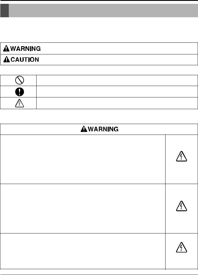
■Incorrect operation due to ignoring instruction will cause harm or damage. The seriousness is classified by the following indications.
This symbol indicates the possibility of death or serious injury.
This symbol indicates the possibility of injury or damage to properties only.
■ Meanings of symbols used in this manual are as shown below.
Be sure not to do.
Be sure to follow the instruction.
Dangerous Voltage
1.1 Cautions in Repair
SAFETY PRECAUTIONS
1.When servicing the unit, set the main SWITCH to OFF and remove the POWER SUPPLY cables.
2. Observe the original lead dress. If a short circuit is found, replace all parts which have been overheated or damaged by the short circuit.
3.After servicing the unit, make an insulation resistance test to protect the customer from being exposed to shock hazards.
INSULATION RESISTANCE TEST
1.Unplug the power cord and connect a jumper between 2 pins (black and white).
2.The grounding conductor (green or green & yellow) is to be open.
3.Measure the resistance value with an ohm meter between the jumpered lead and each exposed metallic part on the equipment.
4.The value should be over 1MΩ.
Be sure to disconnect the power cable plug from the plug socket before disassembling the equipment for a repair.Internal components and circuit boards are at main potential when the equipment is connected to the power cables. This voltage is extremely dangerous and may cause death or severe injury if come in contact with it.
Service Manual 3
Safety Precautions
Do not touch the discharging refrigerant gas during the repair work. The discharging refrigerant gas.The refrigerant gas can cause frostbite.
Release the refrigerant gas completely at a well-ventilated place first. Otherwise, when the pipe is disconnected, refrigerant gas or refrigerating machine oil discharges and it Can cause injury.
When the refrigerant gas leaks during work, execute ventilation. If the refrigerant gas touches to a fire, poisonous gas generates. A case of leakage of the refrigerant and the closed room full with gas is dangerous because a shortage of oxygen occurs. Be sure to execute ventilation.
When removing the front panel or cabinet, execute short-circuit and discharge between high voltage capacitor terminals. If discharge is not executed, an electric shock is caused by high voltage resulted in a death or injury.
Do not turn the air-conditioner ON or OFF by plugging or unplugging the power plug. There is risk of fire or electrical shock.
Do not use a defective or underrated circuit breaker. Use the correctly rated breaker and fuse. Otherwise there is a risk of fire or electric shock.
Install the panel and the cover of control box securely. Otherwise there is risk of fire or electric shock due to dust, water etc.
Indoor/outdoor wiring connections must be secured tightly and the cable should be routed properly so that there is no force pulling the cable from the connection terminals. Improper or loose connections can cause heat generation or fire.
Do not touch, operate, or repaire the product with wet hands. Hoding the plug by hand when taking out. Otherwise there is risk of electric shock or fire.
Do not turn on the breaker under condition that front panel and cabinet are removed.
Be sure to earth the air conditioner with an earthing conductor connected to the earthing terminal.
Conduct repair works after checking that the refrigerating cycle section has cooled down sufficiently. Otherwise, working on the unit, the hot refrigerating cycle section can cause burns.
4 Window Air Conditioner

Safety Precautions
Do not tilt the unit when removing panels. Otherwise, the water inside the unit can spill and wet floor.
Do not use the welder in a well-ventilated place. Using the welder in an enclosed room can cause oxygen deficiency.
Be sure to turn off power switch before connect or disconnect connector, or parts damage may be occurred.
1.2 Inspections after Repair
Check to see if the power cable plug is not dirty or loose. If the plug is dust or loose it can cause an electrical shock or fire.
Do not use a joined power cable or extension cable, or share the same power outlet with other electrical appliances. otherwise, it can cause an electrical shock, excessive heat generation or fire.
Do not insert hands or other objects through the air inlet or outlet while the product is operating. There are sharp and moving parts that could cause personal injury.
Do not block the inlet or outlet of air flow. It may cause product failure
Check to see if the parts are mounted correctly and wires are connected. Improper installation and connections can cause an electric shock or an injury.
Check the installation platform or frame has corroded. Corroded installation platform or frame can cause the unit to fall, resulting in injury.
Be sure to check the earth wire is correctly connected.
After the work has finished, be sure to do an insulation tset to check the resistance is 2[Mohm] or more between the charge section and the non-charge metal section (Earth position). If the resistance value is low, a disaster such as a leak or electric shock is caused at user’s side.
Check the drainage of the indoor unit after the repair. If drainage is faulty the water to enter the room and wet floor.
Service Manual 5

Operation
Operation

 Features


•Designed for COOLING ONLY.
•Powerful and whispering cooling.
•Slide-in and slide-out chassis for the simple installation and service.
•Side air-intake, side cooled-air discharge.
•Built-in adjustable THERMOSTAT
•Washable one-touch filter
•Compact size
•Reliable and efficient rotary compressor

 Control
 Locations
 Function
 of
of Controls


1. Cooling Only Model
• VENTILATION
The ventilation lever must be in the CLOSE position in order to maintain the best cooling
conditions. When a fresh air is necessary in the room, set the ventilation lever OPEN position.
The damper is opened and room air is exhausted.
CLOSE  VENT
VENT  OPEN
OPEN
• THERMOSTAT
Thermostat will automatically control the temperature of the room. Select a higher number for a cooler temperature in the room. The temperature is selected by positioning the knob to the desired position.
The 5 or 6 position is a normal setting for average conditions.
• OPERATION |
|
|
|
Off |
( 0 |
) |
: Turns the air conditioner off. |
MED FAN |
( |
) |
: Permits the medium fan speed operation without |
|
|
|
cooling. |
LOW FAN |
( |
) : Permits the low fan speed operation without |
|
|
|
|
cooling. |
HIGH COOL (  ) : Permits cooling with the high fan speed operation.
MED COOL |
( |
) : Permits cooling with the medium fan speed |
|
|
operation. |
LOW COOL |
( |
) : Permits cooling with the low fan speed opera- |
|
|
tion. |
4 |
5 |
6 |
|
Off |
|
Med |
High |
||
|
|
|
||
|
|
|
Fan |
Cool |
3 |
|
7 |
|
|
2 |
|
8 |
|
|
1 |
|
9 |
Low |
Med |
|
Fan |
Cool |
||
|
|
|
|
Low Cool |
Thermostat |
|
Operation |
||
|
|
Auto Swing |
|
|
|
5 |
Off |
On |
Off |
4 |
6 |
|
||
|
Med |
High |
||
|
|
|
||
|
|
|
Fan |
Cool |
3 |
|
7 |
|
|
2 |
|
8 |
|
|
1 |
|
9 |
Low |
Med |
|
Fan |
Cool |
||
|
|
|
|
Low Cool |
Thermostat |
|
Operation |
||
0
CAUTION: A slight heat odor may come from
0
the unit when first switching to HEAT after the cooling season is over. This odor, caused by
fine dust particles on the heater, will disappear quickly.
6 Window Air Conditioner

2. Heat Pump Model
•HEATER LAMP
When the unit sets heating operation condition, the green lamp is lighted.
When the frost settles on the heat exchanger of the outside, defrosting is made automatically and the green lamp is unlighted. The until it may hiss and the fan motor will stop for 1 to 10 minutes.
This should not be regarded as trouble. After defrosting, the heating operation begins again.
•THERMOSTAT
Turn the thermostat control to the desired setting. The central position is a normal setting for average conditions. You can change this setting, if necessary, in accordance with your temperature preference.
The thermostat automatically controls cooling or heating, but the fan runs continuously whenever the air conditioner is in operation. If the room is too warm, turn the thermostat control clockwise. If the room is too cool, turn the themostat control counterclockwise.
•OPERATION
OFF |
( |
) : Turns the air conditioner off. |
LOW FAN |
( |
) : Permits the low fan speed opera- |
|
|
tion without cooling |
|
|
(or heating). |
LOW COOL ( |
) : Permits cooling with the low |
|
|
|
fan speed operation. |
HIGH COOL ( |
) : Permits cooling with the high |
|
|
|
fan speed operation. |
LOW HEAT ( |
) : Permits heating with the low |
|
|
|
fan speed operation. |
HIGH HEAT ( |
) : Permits heating with the high |
|
|
|
fan speed operation. |
Operation
|
|
|
T |
C |
|
|
|
|
A |
O |
|
||
|
|
E |
|
|
O |
|
COOLER |
WARMER |
H |
|
|
|
L |
|
|
|
|
|
||
HEATER
THERMOSTAT OPERATION
(TYPE1)
Heater
Warmer Cooler
Thermostat |
Operation |
(TYPE2)
Service Manual 7
 Loading...