

Page 1

FastMig
MSF 53, 55, 57
Operating manual • English
Käyttöohje • Suomi
Bruksanvisning • Svenska
Bruksanvisning • Norsk
Brugsanvisning • Dansk
Gebrauchsanweisung • Deutsch
Gebruiksaanwijzing • Nederlands
Manuel d’utilisation • Français
Manual de instrucciones • Español
Instrukcja obsługi • Polski
Инструкции по эксплуатации • По-русски
EN
FI
SV
NO
DA
DE
NL
FR
ES
PL
RU
Page 2

Page 3

OPERATING MANUAL
English
FastMig MSF 53, 55, 57 / © Kemppi Oy / 1515
EN
Page 4

EN
CONTENTS
FastMig MSF 53, 55, 57 / © Kemppi Oy / 1515
1. PREFACE ..................................................................................... 3
1.1 General ................................................................................................................................................................. 3
1.2 Product introduction ................................................................................................................................. 3
1.2.1 Operation control and connectors ..................................................................................................4
1.2.2 Connection of system ......................................................................................................................... 7
1.2.3 DuraTorque™ 400, 4 wheel wire feed mechanism .................................................................... 8
2. INSTALLATION ........................................................................... 9
2.1 Assembly of MIG system ......................................................................................................................... 9
2.2 Accessories corresponding to wire diameter ..........................................................................9
2.3 Mounting of MIG welding gun ........................................................................................................... 9
2.4 Mounting and locking of wire Spool .......................................................................................... 10
2.5 Automatic wire feed to gun ...............................................................................................................10
2.6 Adjustment of pressure ........................................................................................................................10
2.7 Adjustment of tightness of reel brake .......................................................................................11
2.8 Burn back time ............................................................................................................................................ 11
2.9 Ground cable ................................................................................................................................................ 11
2.10 Shield gas ........................................................................................................................................................ 11
2.10.1 Installing gas bottle ..........................................................................................................................12
2.11 Main switch I/O ........................................................................................................................................... 12
2.12 Operation of cooling unit, Fastcool 10 ......................................................................................13
2.13 Hanging ............................................................................................................................................................ 13
3. CONTROL PANELS OPERATIONS ............................................ 13
3.1 SF 51 and SF 54 operations ................................................................................................................ 13
3.2 SF 52 and SF 53 operations ................................................................................................................ 15
3.3 SETUP functions (10) ...............................................................................................................................20
4. OPERATIONS OF REMOTE CONTROL UNITS IN
MSF WIRE FEED UNIT ..............................................................22
5. FASTMIG™ ERROR CODES ....................................................... 23
6. SERVICE, OPERATION DISTURBANCES .................................24
7. ORDERING NUMBERS ............................................................. 25
8. DISPOSAL OF THE MACHINE .................................................. 27
9. TECHNICAL DATA .................................................................... 27
10. WARRANTY POLICY ................................................................. 28
2
Page 5

1. PREFACE
1.1 GENERAL
Congratulations on your choice of the FastMig™ MSF series power source. Reliable and durable,
Kemppi products are aordable to maintain, and they increase your work productivity.
This user manual contains important information on the use, maintenance, and safety of
your Kemppi product. The technical specications of the device can be found at the end of
the manual. Please read the manual carefully before using the equipment for the rst time.
For your safety and that of your working environment, pay particular attention to the safety
instructions in the manual.
For more information on Kemppi products, contact Kemppi Oy, consult an authorised Kemppi
dealer, or visit the Kemppi Web site at www.kemppi.com.
The specications presented in this manual are subject to change without prior notice.
Important notes
Items in the manual that require particular attention in order to minimise damage and
personal harm are indicated with the ’NOTE!’ notation. Read these sections carefully and
follow their instructions.
1.2 PRODUCT INTRODUCTION
Kemppi FastMig™ MSF is wire feeder designed for demanding professional use.
From our product family you can choose equipment intended either for 200-mm or 300-mm
wire reel due to purpose of use. MSF 53 suits for 200-mm and MSF 55 and MSF 57 for 300-mm
wire reel.
For both wire feeder units there are two alternative panels; simple and advanced panels.
Alternative panels for MSF 53 are SF 51 and SF 52, panels for MSF 55 and MSF 57 are SF 53 and
SF 54.
Operations of wire feed unit are controlled and adjusted with microprocessor.
This manual provides instructions on the start-up of the MSF 53, MSF 55 and MSF 57 MIG units
and panels SF 51, SF 52, SF 53 and SF 54 as well as the functions of the wire feed unit.
FastMig MSF 53, 55, 57 / © Kemppi Oy / 1515
EN
3
Page 6
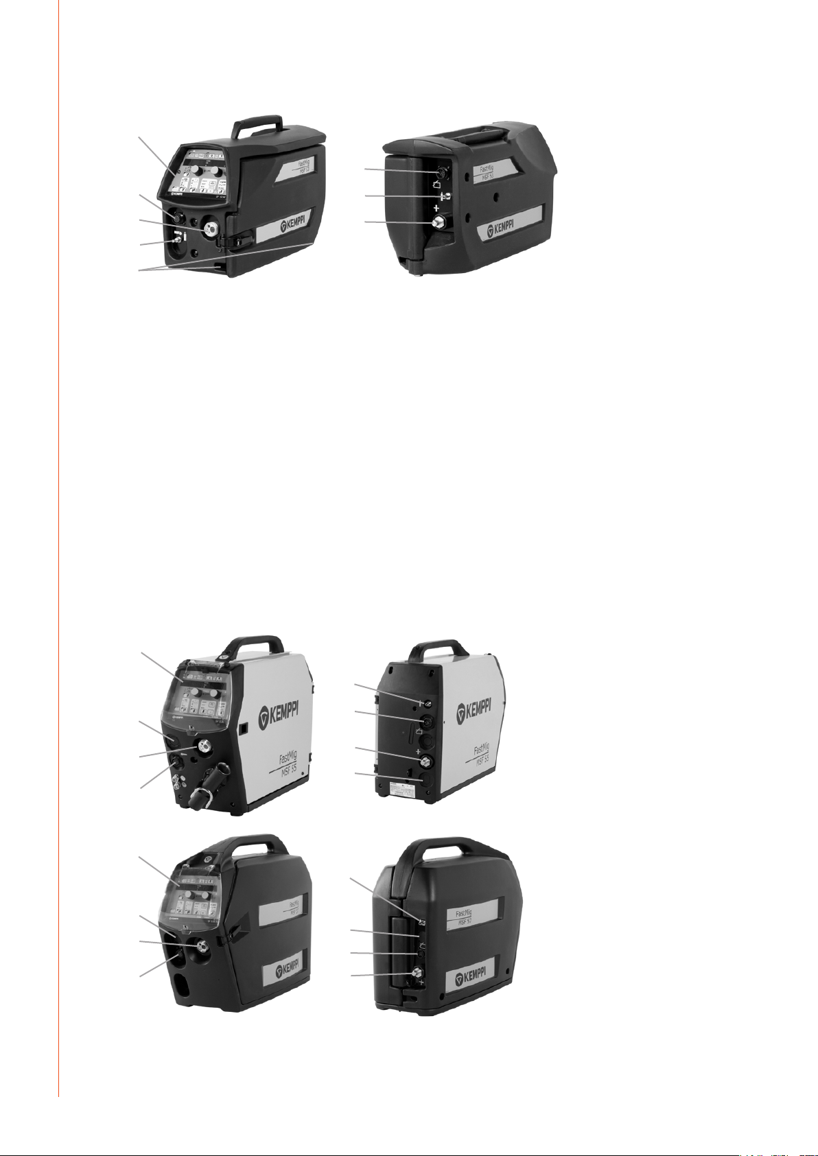
1.2.1 OPERATION CONTROL AND CONNECTORS
1.
6.
EN
FastMig MSF 53, 55, 57 / © Kemppi Oy / 1515
2.
3.
4.
5.
7.
8.
MSF 53
1. Operation panel
2. Connection of remote control unit
3. Connection of welding gun EURO
4. Shield gas ow control
5. Lead-in and clamping of cooling liquid hoses
6. Connection for control cable
7. Shielding gas connection
8. Welding current cable connector
MSF 55, MSF 57
1. Operation panel
2. Assembly space for push/pull gun control connector (accessory)
3. Connection of welding gun EURO
4. Connection of remote control unit
5. Shielding gas connection
6. Connection for control cable
7. Welding current cable connector
8. Lead-in and clamping of cooling liquid hoses
1.
5.
2.
3.
4.
1.
2.
3.
4.
6.
7.
8.
5.
6.
7.
8.
4
Page 7
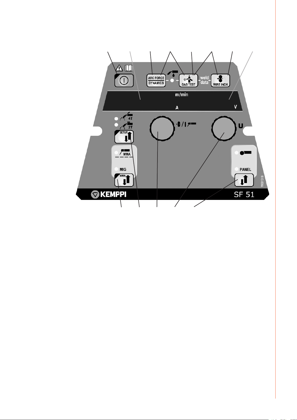
Functions of SF 51 and SF 54 function panel
1. 2.
3. 4. 6.5. 7.
8.
FastMig MSF 53, 55, 57 / © Kemppi Oy / 1515
10.
1. Main switch
2. Display of wire feed speed/welding current
3. Selection of MIG dynamics for adjustments
4. Selection of gas/water cooled MIG gun
5. Gas purge
6. Weld data: Last used welding parameters shown in displays
7. Wire inch
8. Display of set value of welding voltage/voltage during welding
9. Selection of MIG/MMA process
10. a) Selection of gun switch function
b) Changing of basic parameters of the unit, SETUP (long pressing)
11. a) Adjustment of wire feed speed
b) Selection of SETUP parameters
12. a) Adjustment of welding voltage
b) Adjustment of MIG dynamics
c) Adjustment of SETUP parameters
13. Manual control/remote control unit selection
11.9.
13.12.
EN
5
Page 8
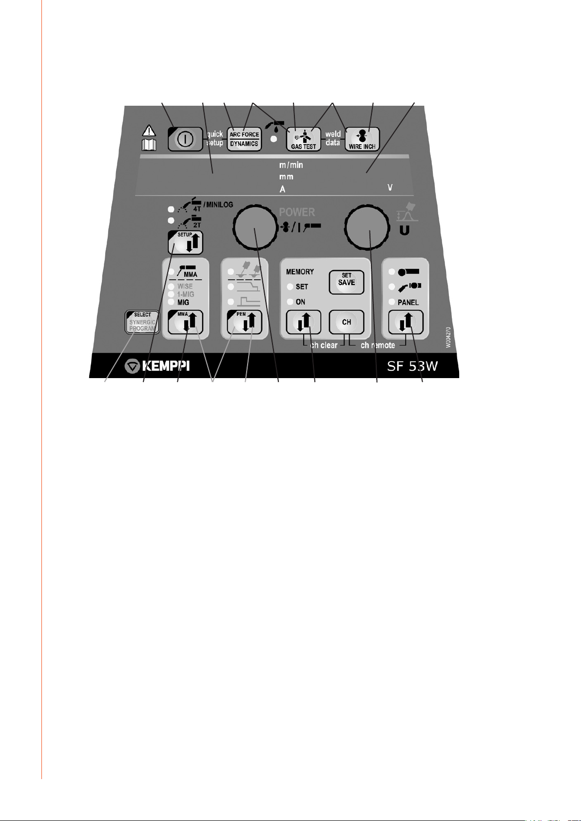
Functions of SF 52 and SF 53 function panel
FastMig MSF 53, 55, 57 / © Kemppi Oy / 1515
1. 2.
3.
4. 6.5. 7.
8.
EN
9.
1. Main switch
2. a) Wire feed speed/welding current/sheet strength display
b) Display of selected adjustable parameter
3. Activation of welding dynamics adjustment
4. Selection of gas/water cooled MIG gun
5. Gas purge
6. Weld data: Last used welding parameters shown in displays
7. Wire inch
8. a) Welding voltage display
b) Display of value of selected adjustable parameter
9. 1-MIG selection check/1-MIG welding arc selection activation
10. a) Selection of MIG process: 2T/4T
b) Changing of basic parameters of the unit, SETUP (long pressing)
11. Selection of welding process MIG,1-MIG, MMA, FR-MIG *)
12. Activation of additional MIG function parameter adjustment
13. Selection of additional MIG functions
14. a) Adjustment of wire feed speed
b) Adjustment of welding power setting (1-MIG)
c) Adjustment of rod current
d) Selection of SETUP parameter
e) Selection of 1-MIG arc (material)
15. Memory channels, storage of MIG parameters
16. a) Welding voltage display
b) Adjustment of length of welding arc (1-MIG)
c) Adjustment of MIG dynamics
d) Adjustment of SETUP parameter
e) Selection of 1-MIG arc
17. Manual control/remote control unit selection
*) FR-MIG for root pass welding is not included in standard delivery
10.
11.
13.12.
14.
15 16. 17.
6
Page 9
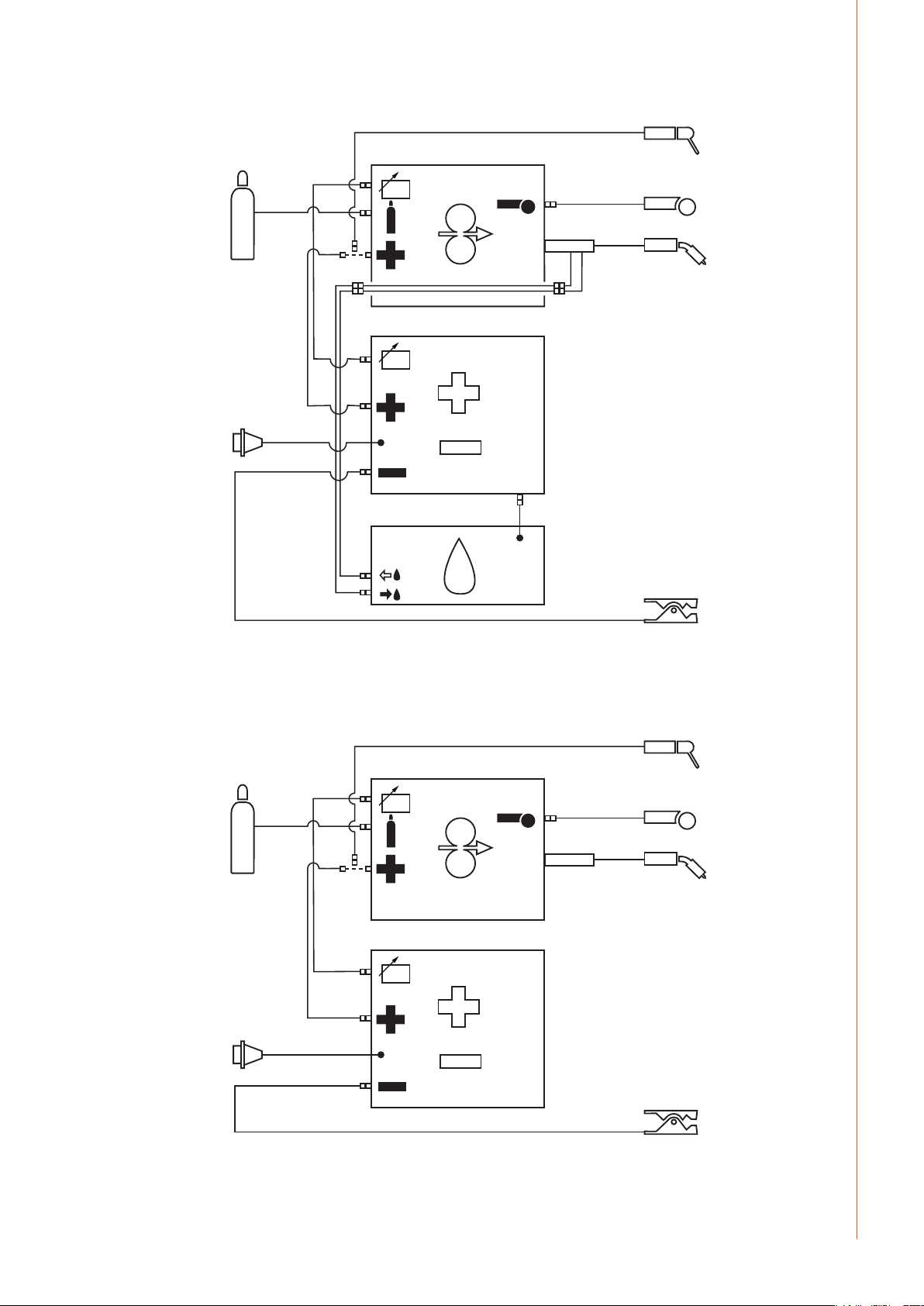
1.2.2 Connection of system
FastMig MSF 53, 55, 57 / © Kemppi Oy / 1515
EN
7
Page 10
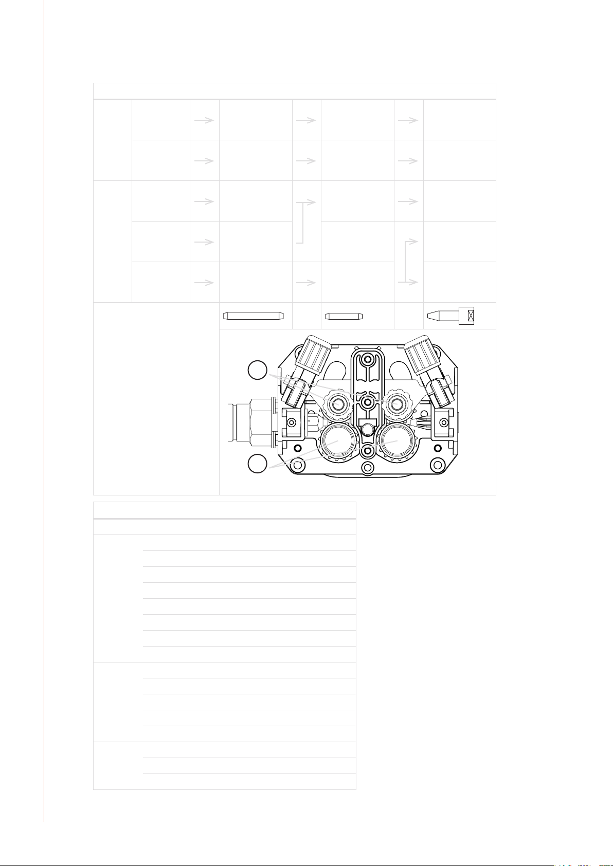
1.2.3 DuraTorque™ 400, 4 wheel wire feed mechanism
Wire guide tubes
Ss, Al, Fe,
Mc, Fc
Fe, Mc, Fc ø 0.6 ... 0.8 mm ø 1.0/67 mm,
FastMig MSF 53, 55, 57 / © Kemppi Oy / 1515
ø 0.6 ... 1.6 mm ø 2.5/64 mm,
W000762,
silver, plastic
ø 1.6 ... 2.4 mm ø 3.5/64 mm,
W001430,
silver, plastic
W001432,
white, steel
ø 0.9 ... 1.6 mm ø 2.0/64 mm,
W001433,
orange, steel
ø 1.6 ... 2.4 mm ø 4.0/63 mm,
W001434,
blue, steel
ø 2.5/33 mm,
W000956,
silver, plastic
ø 3.5/33 mm,
W001431,
silver, plastic
ø 2.0/33 mm,
W001435,
orange, steel
ø 4.0/33 mm,
W001436,
blue, steel
ø 2.0 mm,
W000624,
plastic
ø 3.5 mm,
W001389,
plastic
ø 2.0 mm,
W000624,
plastic
ø 3.5 mm,
W001389,
plastic
ø 3.5 mm,
W001391,
brass
EN
Wire feed rolls
Fe, Ss, Al,
V-groove
Fe, Fc, Mc,
knurled
Fe, Fc, Mc,
Ss, Al,
U-groove
2.
1.
ø mm colour drawing pressing
0.6 pale grey W001045 W001046
0.8/0.9 white W001047 W001048
1.0 red W000675 W000676
1.2 orange W000960 W000961
1.4 brown W001049 W001050
1.6 yellow W001051 W001052
2.0 grey W001053 W001054
2.4 black W001055 W001056
1.0 red W001057 W001058
1.2 orange W001059 W001060
1.4/1.6 yellow W001061 W001062
2.0 grey W001063 W001064
2.4 black W001065 W001066
1.0 red W001067 W001068
1.2 orange W001069 W001070
1.6 yellow W001071 W001072
8
Page 11

2. INSTALLATION
2.1 ASSEMBLY OF MIG SYSTEM
Assemble the units in order mentioned below and follow mounting and operation
instructions
which are delivered in packages.
1. Installation of power source
Read paragraph: ”Installation” in operation instructions for Kemppi FastMig™ power sources
and carry out the installation according to that.
2. Mounting of KMS power sources to transport wagon
Read and follow the instructions given in the transport cart installation/assembly manual
3. Mounting the FastMig™ MSF on to the power source
Screw the fastening pivot on the power source. Lift the wire feeder on fastening pivot.
4. Connecting cables
Connect the cables in accordance with the equipment notes provided.
The polarity of the welding wire (+ or -) can be changed by replacing the MSF welding current
cable and return current cable with the Kemppi FastMig™ power source welding cable
connector.
5. Mounting of FastMig™ wire feed units to boom
NOTE! Wire feed unit must be mounted to boom in such a way that its chassis is galvanic
separated both from swing arm and boom.
Suspension angle of wire feed unit can be changed by moving xing point in handle.
FastMig MSF 53, 55, 57 / © Kemppi Oy / 1515
2.2 ACCESSORIES CORRESPONDING TO WIRE DIAMETER
Wire feed rolls are available with plain groove, knurled groove and with U groove for dierent
purposes.
Feed rolls with plain groove: Universal feed roll for welding of all kinds of wires.
Feed rolls with knurled groove: Special feed roll for cored wires and steel wires.
Feed rolls with U groove: Special feed roll for aluminium wires.
In delivery FastMig™ wire feed units are equipped with 1.2 mm orange feed rolls with
V-groove and with silver wire guide tubes for welding ller wires of 0.6 – 1.6 mm.
2.3 MOUNTING OF MIG WELDING GUN
In order to ensure trouble-free welding check in operation instructions of gun used by you
that wire guide tube and contact tip of gun are according to manufacturer’s recommendation
suitable to be used for wire feed diameter and type in question. To tight a wire guide tube
might cause for wire feed unit a bigger stress than normally as well as disturbances in
wire feed. Screw snap connector of gun tight that there won’t come any voltage losses on
connecting surface. A loose connection will heat gun and wire feed unit and feeder.
MSF wire feed units are equipped with backup functions in case of overheating of the liquidcooled PMT gun or overloading of the wire feed motor. The backup function is as follows (see
also the error code information, page 21):
1. The Kemppi PMT gun thermal protection goes into action. When this occurs, the unit
interrupts welding and the message ’Err 153’ appears on the panel (ls) display.
2. The wire feed motor can overload - due to, e.g., gun clogging. In this event, the unit
interrupts welding and the text ’Err 162’ appears on the panel display. ’Err 161’ = warning.
Error codes disappear on the next start-up if the cause of the error has been eliminated (i.e.,
the gun has cooled down or the motor is no longer overloaded).
EN
9
Page 12

2.4 MOUNTING AND LOCKING OF WIRE SPOOL
LOCKED OPEN
• Releaselockingnailsofwirereelhubbyturninglockingknobaquarterround.
• Mountthespoolatitsplace.Noterotatingdirectionofspool!
• Lockthespoolwithlockingknob,lockingnailsofhubremaintooutsidepositionandwill
lock the spool.
A
B
FastMig MSF 53, 55, 57 / © Kemppi Oy / 1515
• Releasethelockingnub(A)!
• Mountthespoolatitsplace.Noterotatingdirectionofspool.
• Lockthespoolwithlockingnut.
NOTE! Check that in ller wire reel there are no parts sticking out, which could e.g. chafe against
chassis or door of wire feed unit. Dragging parts might expose chassis of wire feed unit under
voltage.
EN
2.5 AUTOMATIC WIRE FEED TO GUN
Automatic wire feed makes change of wire reel more rapid. In reel change the pressure of feed
rolls need not to be released and ller wire goes automatically to correct wire line.
• Makesurethatgrooveoffeedrollmatchesthediameterofweldingwireused.
• Releasethewireendfromreelandcutothebentlength.Becarefulthatthewiredoes
notspillfromthereeltosides!
• Straightenabout20cmofthewireandseethattheendofithasnosharpedges(leoif
necessary). A sharp edge may damage the wire guide tube and contact tip of the welding
gun.
FastMig™ MSF wire feed units:
• Drawabitofloosewirefromwirereel.Feedwirethroughbacklinertofeedrolls.Donot
releasepressureoffeedrolls!
• Pressthegunswitchandfeedabitwireuntilwiregoesthroughfeedrollstogun.Seethat
wireisingroovesofbothfeedrollpairs!
• Pressstillthegunswitchuntilwirehascomethroughcontacttip.
Automatic feed may sometimes fail with thin wires (Fe, Fc, Ss: 0,6...0,8 mm, Al: 0,8...1,0 mm). In
that case you might have to open feed rolls and feed wire manually through feed rolls.
2.6 ADJUSTMENT OF PRESSURE
Adjust the pressure of feed rolls with the control screw (20) so that the wire is fed into the wire
guide tube evenly and allows a little braking when coming out from the contact tip without
slipping at the feed rolls.
NOTE! Excessive pressure causes attening of the ller wire and damage to the coating. It also
causes undue wear of the feed rolls as well as friction.
10
Page 13

2.7 ADJUSTMENT OF TIGHTNESS OF REEL BRAKE
Brake force is adjusted through hole in locking device of spool hub by screwing the control
screw (A) with screwdriver.
A
Brake force is adjusted by screwing the brake force adjusting screw (B), tightening clockwise
direction.
A
Adjust brake force as so big that the wire is not allowed to become too loose on the reel so
that it would spill from the reel when the rotation of the reel stops. Need for brake force is
increased with increase of wire feed speed.
Since the brake loads for its part the motor, you shouldn’t keep it unnecessarily tight.
2.8 BURN BACK TIME
Electronics of feed unit controls stopping of welding automatically so that the wire end
doesn’t melt fastened to the contact tip or the work piece. Automatics work regardless of the
wire feed speed. Can be adjusted also from SETUP-menu ('PoC').
2.9 GROUND CABLE
Connecting of earth cable should be preferably connected directly to the welding material.
Contact surface of press always should be as large as possible.
Cleanthefasteningsurfacefrompaintandrust!
Use in your MIG equipment at least 70 mm². Thinner cross-sectional areas might cause
overheating of connectors and insulations.
Make sure that the welding gun in your use is designed for max. welding current needed by
you!
Neveruseadamagedweldinggun!
B
FastMig MSF 53, 55, 57 / © Kemppi Oy / 1515
EN
2.10 SHIELD GAS
NOTE! Handle gas bottle with care. There is a risk for injury if gas bottle or bottle valve is damaged!
For welding stainless steels, mixed gases are normally used. Check that the gas bottle valve
is suitable for the gas. The ow rate is set according to the welding power used in the job. A
suitable ow rate is normally 8 – 10 l/min. If the gas ow is not suitable, the welded joint will
be sporous. Contact your local Kemppi-dealer for choosing gas and equipment.
11
Page 14

2.10.1 Installing gas bottle
EN
FastMig MSF 53, 55, 57 / © Kemppi Oy / 1515
A
NOTE! Always fasten gas bottle properly in vertical position in a special holder on the wall or on a
carriage. Remember to close gas bottle valve after having nished welding.
Parts of gas ow regulator
A Gas bottle valve
B Press regulation screw
C Connecting nut
D Hose spindle
E Jacket nut
F Gas bottle pressure meter
G Gas hose pressure meter
The following installing instructions are valid for most of the gas ow regulator types:
1. Step aside and open the bottle valve (A) for a while to blow out possible impurities from
the bottle valve.
2. Turn the press regulation screw (B) of the regulator until no spring pressure can be felt.
3. Close needle valve, if there is one in the regulator.
4. Install the regulator on bottle valve and tighten connecting nut (C) with a wrench.
5. Install hose spindle (D) and jacket nut (E) into gas hose and tighten with hose clamp.
6. Connect the hose with the regulator and the other end with the wire feed unit. Tighten
the jacket nut.
7. Open bottle valve slowly. Gas bottle pressure meter (F) shows the bottle pressure.
Note!Donotusethewholecontentsofthebottle.Thebottleshouldbelledwhenthe
bottle pressure is 2 bar.
8. Open needle valve if there is one in the regulator.
9. Turn regulation screw (B) until hose pressure meter (G) shows the required ow (or
pressure). When regulating ow amount, the power source should be in switched on and
the gun switch pressed simultaneously.
Close bottle valve after having nished welding. If the machine will be out of use for a long
time, unscrew the pressure regulation screw.
F
C
G
B
E
D
2.11 MAIN SWITCH I/O
When you turn the main switch of the Kemppi FastMig™ power source into I-position, the pilot
lamp closest to this switch will light up, indicating the power source is ready for welding. The
equipment is returned to the position which it last carried out before the main switch was
turned to zero position.
NOTE! Always start and switch o the machine with the main switch, never use the mains plug as
a switch.
12
Page 15

2.12 OPERATION OF COOLING UNIT, FASTCOOL 10
Operation of cooling unit is controlled in such a way that pump is started when welding is
started. After welding stop pump is rotating for approx. 5 min cooling the gun and the cooling
liquid to ambient temperature.
Read in operation instructions for the Fastcool 10 unit the trouble situations of the liquid
circulation system and protection against torch etc. damage.
2.13 HANGING
MSF 53 needs hanging frame (accessorie) for mounting, do not hang from the handle. MSF 55
and MSF 57 can be hanged from hanging kit available as an accessorie.
3. CONTROL PANELS OPERATIONS
3.1 SF 51 AND SF 54 OPERATIONS
1. 2.
3. 4. 6.5. 7.
8.
FastMig MSF 53, 55, 57 / © Kemppi Oy / 1515
10.
11.9.
13.12.
Main switch, ON/OFF (1)
The wire feed unit remains in the OFF position when the power source is switched on, thus
preventing start-up. ’OFF’ is shown on the display.
When the ON/OFF button is pressed for more than 1 second, the unit starts up. The unit is now
ready for welding and will automatically return back to it previous position, before the power
was cut o. The wire feed unit starts up also by pressing three (short) times the switch of the
welding gun.
Basic settings and displays (11, 12, 2, 8)
The wire feed speed is set via potentiometer (11), the value of which is shown on display (2).
The welding voltage is set via potentiometer (12), the value of which is shown on display (8).
During welding, display (2) shows the actual welding current value and display (8) shows
welding voltage.
When MIG dynamics adjustment is activated via button (3), the MIG dynamics value is
adjusted through potentiometer (12) (see ’Adjustment of MIG dynamics’).
With electrode welding (MMA), the welding current value is set via the potentiometer, the
value of which is shown on display (2). Display (8) shows the idling voltage of the power
source. During welding, display (2) shows the actual welding current value and display (8)
shows the welding voltage.
EN
13
Page 16

FastMig MSF 53, 55, 57 / © Kemppi Oy / 1515
When the adjustment of SETUP parameters has been conrmed with long press on button
(10b), the adjustable parameter is selected via potentiometer (11), the name of which is
shown on display (2). Parameter value is selected from potentiometer (12), value can be seen
on display (8). (See the information on SETUP functions).
Selection of MIG operating procedure (10a)
MIG 2T: MIG welding with two-sequence procedure of welding gun start switch
1. switch pressed: welding starts
2. switch released: welding stops
MIG 4T: MIG welding with four-sequence procedure of welding gun start switch
1. switch pressed: shielding gas ow starts
2. switch released: welding starts
3. switch pressed: welding stops
4. switch released: shielding gas ow stops
Adjustment of MIG dynamics/Arc Force (3)
With MIG welding dynamics adjustment is inuenced on welding stability and spatter
amount. Zero setting is recommended basic setting. Values –> min (-1...-9), softer arc for
reduced spatter amount. Values –> max (1...9), harder arc for increased stability and when
100 % CO₂ shielding gas is used when welding steel.
With electrode welding Arc Force adjustment is inuenced on welding stability. Adjustment
is needed for using dierent types of electrodes. Control range (-9...0) is commonly used for
welding electrodes for stainless steel. Control range (0...+9) is used for harder arc characteristic
to increase stability, e.g. for welding with thicker basic electrodes and using lower current
value than recommendated. Factory set value (0) is a good general use for adjusting the
roughness of the arc.
EN
Gas test (5)
The gas test button opens the gas valve without activating the wire feed or power source.
By default, gas ows for 20 seconds. The display shows the remaining gas ow time.
The default time for gas ow can be adjusted via the right-hand potentiometer within a 10- to
60-second range. The new time setting is recorded in the memory.
The gas ow can be discontinued by pressing the ON/OFF button or the start switch of the
gun.
Wire feed test (7)
The wire feed switch starts the wire feed motor without opening the gas valve and without
engaging the power source. The default wire feed speed is 5 m/min. The speed can be
adjusted via the right-hand potentiometer.
When the button is released, the wire feed stops. Unit operation returns to normal approx.
3 seconds after release of the button or if the ON/OFF button is pressed briey.
Selection of liquid- /gas-cooled MIG gun (4)
Selection of liquid-cooled/gas-cooled MIG gun is activated by pressing buttons 3 and 5
simultaneously (for more than 1 second). When ‘Gas’ is shown on the display, the welding
equipment will assume that a gas-cooled MIG gun has been connected. If the above buttons
are pressed again, the text ’CooLEr’ appears on the display and the LED indicating liquid
cooling selection lights up. In this case, the welding equipment will assume that a liquidcooled MIG gun has been connected to the equipment. When liquid cooling is selected, the
liquid cooling unit will start up in connection with the next equipment start-up.
Weld data (6)
The weld data function is activated by pressing buttons 5 and 7 simultaneously. The weld data
function returns the welding current and voltage values that were in use when welding was
discontinued to the displays.
14
Selection of welding process (9)
Electrodewelding(MMA)isselectedbypressingthebuttonfor>1second.N.B.!When
electrode welding is selected, the power source, the electrode holder connected to it and the
MIG gun become energised (idling voltage).
Page 17

Use of remote control units (13)
Remote control unit is connected to the device by pressing button 13. The wire feed speed
and welding voltage setting operations are performed via remote control. In this case,
potentiometers 11 and 12 of the panel are disconnected.
3.2 SF 52 AND SF 53 OPERATIONS
1. 2.
4. 6.5. 7.
8.
FastMig MSF 53, 55, 57 / © Kemppi Oy / 1515
9.3.10.
11.
14.
13.12.
15 16. 17.
Main switch, ON/OFF (1)
The wire feed unit remains in the OFF position when the power source is switched ON,
thus preventing start-up. OFF is shown on the display. When the ON/OFF button is pressed
for more than 1 second, the unit starts up. The unit is now ready for welding and will
automatically return to previous position. The unit starts up also by pressing three times
shortly the start switch of the gun.
Basic settings and displays (14, 16, 2, 8)
With MIG welding, the wire feed speed is set via potentiometer No. 14, the value of which is
shown on display No. 16. The welding voltage is set via potentiometer No. 16, the value of
which is shown on display No. 8. During welding, display 2 shows the actual welding current
value and display 8 shows the welding voltage.
With electrode welding (MMA), the welding current value is set via the potentiometer, the
value of which is shown on display No. 2. Display 8 shows the idling voltage of the power
source. During welding, display 2 shows the actual welding current value and display 8 shows
the welding voltage.
When MIG dynamics/electrode welding Arc force adjustment is activated via button No. 3,
the value is adjusted via potentiometer No. 16 (see the information on adjustment of MIG
dynamics/arc force).
With Synergic 1-MIG welding, the power value is set via potentiometer 14 and the length of
the arc via potentiometer 16 (see ’1-MIG welding’).
When the adjustment of SETUP parameters has been conrmed with a long press on button
10, the adjustable parameter is selected via potentiometer No. 14, the name of which is shown
on display
No. 2. The parameter’s value is set via potentiometer No. 16, the value of which is shown on
display No. 8 (see ’SETUP functions’).
EN
Selection of MIG operating procedure (10)
MIG 2T: MIG welding with two-sequence procedure of welding gun start switch
1. switch pressed: welding starts
2. switch released: welding stops
15
Page 18

MIG 4T: MIG welding with four-sequence procedure of welding gun start switch
1. switch pressed: shielding gas ow starts
2. switch released: welding starts
3. switch pressed: welding stops
4. switch released: shielding gas ow stops
Adjustment of MIG dynamics/Arc Force (3)
With MIG welding dynamics adjustment is inuenced on welding stability and spatter amount.
Zero setting is recommended basic setting. Values –> min (-1...-9), softer arc for reduced spatter
amount. Values –> max (1...9), harder arc for increased stability and when 100 % CO₂ shielding
gas is used in welding of steel.
With electrode welding Arc Force adjustment is inuenced on welding stability. Adjustment
is needed for using dierent types of electrodes. Control range (-9...0) is commonly used for
welding electrodes for stainless steel. Control range (0...+9) is used for harder arc characteristic
to increase stability, e.g. for welding with thicker basic electrodes and using lower current
value than recommendated. Factory set value (0) is a good general use for adjusting the
roughness of the arc.
EN
FastMig MSF 53, 55, 57 / © Kemppi Oy / 1515
Gas test (5)
The gas test button opens the gas valve without activating the wire feed or power source. Gas
ows for 20 seconds by default. The display shows the remaining gas ow time. The default
time of gas ow can be adjusted via the right-hand potentiometer within a range of 10 to 60
seconds. The new time setting is recorded in the memory. The gas ow can be discontinued
by pressing the ON/OFF button or the start switch of the gun.
Wire feed test (7)
The wire feed switch starts the wire feed motor without opening the gas valve and without
engaging the power source. The default wire feed speed is 5 m/min. The speed can be
adjusted via the right-hand potentiometer. When the button is released, the wire feed stops.
Operation returns to normal approx. 3 seconds after release of the button or if the ON/OFF
button is pressed briey.
Selection of liquid- /gas-cooled MIG gun (4)
Selection of liquid-cooled/gas-cooled MIG gun is activated by pressing buttons 3 and 5
simultaneously (for more than 1 second). When ’Gas’ is shown on the display, the welding
equipment will assume that a gas-cooled MIG gun has been connected. If the above buttons
are pressed again, the text ’CooLEr’ appears on the display and the LED indicating liquid
cooling selection lights up. In this case, the welding equipment will assume that a liquidcooled MIG gun has been connected. When liquid cooling has been selected, the liquid
cooling unit will start up in connection with the next equipment start-up.
Weld data (6)
The weld data function is activated by pressing buttons 5 and 7 simultaneously. The weld data
function returns the welding current and voltage values to the displays that were in use when
welding was discontinued.
16
Selection of welding process (11)
The welding process – normal MIG, 1-MIG or FR-MIG – can be chosen by the welding process
selection button. In normal MIG welding wire feed speed and welding voltage is adjusted
separately. In synergic 1-MIG and FR-MIG welding the welding voltage and other parametres
relatedtoweldingareoptimallyboundtoeachother!Insynergicweldingthesettingfor
power and arc lenght are adjusted.
FR-MIG welding is the facility provided separately, so the function is not in every equipment.
Electrodewelding(MMA)isselectedbypressingthebuttonfor>1second.N.B.!When
electrode welding is selected, the power source, the electrode holder connected to it and the
MIG gun become energised (idling voltage).
Settings selection button (17)
The settings selection button is used to choose the basic settings required. Active settings are
indicated by an LED pilot lamp. Settings are performed manually via the panel potentiometers
Page 19

or remotely via the remote control unit linked to the unit’s remote-control connector. If
settings are chosen to be performed via the gun controller connected to the welding gun,
the wire feed speed / setting for power (1-MIG) will be adjusted via the gun controller and the
welding voltage/arc length (1-MIG) adjusted via panel potentiometer No. 16.
Note!Remotecontrolorgunsettingscanbechosenonlyifthecontrollerinquestionis
connected to the equipment, and in gun control the SETUP parameter ’GUN’ is position ”ON”.
Additional MIG functions (13)
Activation of additional MIG functions
Functions can be added to wire feeder by buing a specic code for it (=licence). The code can
be programmed via wire feeder bus address or via panel. Instructions for programming the
code via wire feeder bus address are on programming manual.
Programming from panel:
1. Go to SETUP functions by a long press on button SETUP.
2. Choose with left potentiometer parameter Code Entering (’Cod’) and adjust right
potentiometer to Enter (’Ent’).
3. Press shortly on REMOTE button.
4. You can see on left display number one (1), programm the rst value of the code on right
potentiometer. Programmed value can be seen on right display.
5. Choose next value programming with the potentiometer on left.
6. Programm the same value seen on left display with right potentiometer.
7. Go back to point 5, until all values of the code have been programmed.
8. Approve the code by a short press on button REMOTE.
9. If code programming is succeeded, on panel can be seen text ’Suc cEs’. If code
programming failed, there is an error code on panel. (See 5. FastMig™ error codes).
10. You can remove from programming mode at any time by pressing shortly ON/OFF button
(ESC function).
The selection button for additional MIG functions can be used to activate the slow start
(’Creep Start’), hot start, or crater levelling (’Crater Level’) function. Further presses of the
selectionbuttoncanselectoneormoreoftheabovefunctions.N.B.!Onlytheavailable
additional functions for each method can be selected.
Parameters related to these functions are set via the SETUP function (see ’SETUP functions’).
The purpose of Creep Start is to facilitate the initial weld – e.g., when welding with a high wire
feed speed. The wire feed speed is kept low until the wire touches the work piece and the
current begins to ow. Creep Start can be selected with normal MIG welding or with Synergic
1-MIG welding.
The purpose of the Hot Start function is to reduce initial welding errors when welding highly
heat-conductive materials such as aluminium. Hot Start can be selected when using Synergic
1-MIG welding and when the 4T operating mode is selected. In this case, when the start
switch of the gun is held down, a xed pre-gas time is displayed after which welding starts at
the level determined by the SETUP mode’s Hot Start parameter, returning to the normal level
when the gun switch is released.
Stopping is performed as with the normal 4T function.
The purpose of crater levelling is to reduce welding defects caused by end cratering. The
Crater Level function can be selected when using Synergic 1-MIG welding and when the 4T
operating mode is selected.
When the gun switch is pressed down in connection with termination of welding, the
welding power drops to the crater-lling level selected previously. The crater lling function is
discontinued by releasing the gun switch.
The values of parameters related to additional MIG functions can be changed either with the
SETUP function (see ’SETUP’) or with the Quick SETUP function. Quick SETUP is activated by
simultaneously pressing buttons 13 and 10. In this way, parameters related to MIG additional
functions can be set.
Parameters are selected for adjustment either with button 13 or via potentiometer No. 14. The
value of the parameter is set via potentiometer No. 16. The value is immediately recorded in
the memory.
FastMig MSF 53, 55, 57 / © Kemppi Oy / 1515
EN
17
Page 20

EN
FastMig MSF 53, 55, 57 / © Kemppi Oy / 1515
Memory functions (15)
Storage of settings
The memory functions can be used to record useful welding values in the memory. There are
ten dierent memory locations: 0 … 9.
In addition to welding values (wire feed speed, welding voltage), function options such as
2T/4T, Creep Start, and Crater Level are recorded in the memory.
Storage in memory is performed as follows:
1. Press the MEMORY button twice; the SET light begins to ash if the channel is not in use. If
thechannelisinuse,thelightremainslit.N.B.!Ifthememoryisempty,presstheMEMORY
key once to get in SET mode.
2. Select the desired memory channel with the CH key.
3. Make the settings and store them in the memory by pressing the SAVE button.
4. Press the MEMORY key twice. Notice that the ON light is lit.
5. Begin welding.
If you wish to change some values, the light must be switched from the ON setting to the SET
setting to enable you to select the required parameters. Press the SAVE button to complete
the procedure. It is also possible to save the parameters of the current weld by pressing SET
when the memory function is in OFF status (all lights o ). The channel can be cleared by
pressing MEMORY and the CH button simultaneously in SET mode.
Use of stored settings
1. Press the MEMORY button.
2. Select the memory channel via the CH button.
3. Begin welding.
The Ch remote function enables selection of memory channels via the selection controller
located on the gun. The function is activated by pressing buttons 17 and CH simultaneously.
When the CH-remote is activated the light in remote control or in gun control starts to ash.
Synergic 1-MIG or FR-MIG welding (9, 11)
In Synergic 1-MIG welding, the optimal welding parameters for the welding wires and gas
used are recorded in the unit. The welding is controlled by adjusting the welding power and
arc length.
Synergic FR-MIG process is meant for root bass welding. Welding parametres and shape of
short circuit responce are optimized for root bass welding.
Welding arc/programme selection:
Before commencing welding, a welding arc/programme suited to the welding wire and gas
used must be chosen from the instructions on the inner surface of the MSF door.
Arc selection is activated by pressing button No. 9 for >1 second. In this case, displays 2 and
8 begin to ash and the material group is selected from the left-hand potentiometer and the
welding arc/programme for the material group in question from the right potentiometer; see
the enclosed table.
The selected programme is immediately recorded in the memory. To get back to normal status
press ON/OFF (1) key, or Synergic PROGRAM button (9).
Use of a selected welding arc/programme:
Select the relevant welding process with the 1-MIG selection button (11). Check that the
welding arc/programme corresponds to the welding wire and shield gas in use. The check
is performed by briey pressing the Synergic PROGRAM button (9), after which the displays
show the material group and the programme number. Consult the above-mentioned table for
the wire type and gas that correspond with the programme number.
Set the desired welding power via potentiometer 14 and the arc length via potentiometer 16.
18
Page 21

FastMig™ synergic MIG-programs
1-MIG 1-MIG
Prog Wire mmMaterial Gas mixture Prog Wire mmMaterial Gas mixture
Fe-group SS-group
101 0.8 Fe Ar+18%-25%CO
102 0.9 Fe Ar+18%-25%CO
103 1.0 Fe Ar+18%-25%CO
104 1.2 Fe Ar+18%-25%CO
106 1.6 Fe Ar+18%-25%CO
111 0.8 Fe CO
112 0.9 Fe CO
113 1.0 Fe CO
114 1.2 Fe CO
116 1.6 Fe CO
121 0.8 Fe Ar+8%CO
122 0.9 Fe Ar+8%CO
123 1.0 Fe Ar+8%CO
124 1.2 Fe Ar+8%CO
126 1.6 Fe Ar+8%CO
152 0.9 FEMC Ar+18%-25%CO
154 1.2 FEMC Ar+18%-25%CO
164 1.2 FEMC CO
174 1.2 FEFC rutile Ar+18%-25%CO
184 1.2 FEFC rutile CO
194 1.2 FEFC basic Ar+18%-25%CO
²
²
²
²
²
²
²
²
²
²
²
²
201 0.8 SS-316 Ar+2%CO
202 0.9 SS-316 Ar+2%CO
²
203 1.0 SS-316 Ar+2%CO
²
204 1.2 SS-316 Ar+2%CO
²
206 1.6 SS-316 Ar+2%CO
²
211 0.8 SS-316 Ar+30%He+1%O
²
212 0.9 SS-316 Ar+30%He+1%O
213 1.0 SS-316 Ar+30%He+1%O
214 1.2 SS-316 Ar+30%He+1%O
216 1.6 SS-316 Ar+30%He+1%O
221 0.8 SS-309 Ar+2%CO
222 0.9 SS-309 Ar+2%CO
223 1.0 SS-309 Ar+2%CO
224 1.2 SS-309 Ar+2%CO
231 0.8 SS-309 Ar+30%He+1%O
232 0.9 SS-309 Ar+30%He+1%O
233 1.0 SS-309 Ar+30%He+1%O
²
234 1.2 SS-309 Ar+30%He+1%O
²
242 0.9 FC-316 Ar+18%-25%CO
244 1.2 FC-316 Ar+18%-25%CO
²
252 0.9 FC-316 CO
254 1.2 FC-309L Ar+18%-25%CO
²
²
²
²
²
²
²
²
²
²
²
Al-group Fe-group
303 1.0 Al-5356 Ar 802 0.9 Fe Ar+18%-25%CO
304 1.2 Al-5356 Ar 803 1.0 Fe Ar+18%-25%CO
306 1.6 Al-5356 Ar 804 1.2 Fe Ar+18%-25%CO
313 1.0 AL-4043 Ar 812 0.9 Fe CO
314 1.2 Al-4043 Ar 813 1.0 Fe CO
316 1.6 Al-4043 Ar 814 1.2 Fe CO
²
²
²
SPE-group SS-group
401 0.8 CuSi 3 Ar 822 0.9 SS-136 Ar+2%CO
402 0.9 CuSi 3 Ar 823 1.0 SS-316 Ar+2%CO
403 1.0 CuSi 3 Ar 824 1.2 SS-316 Ar+2%CO
404 1.2 CuSi 3 Ar 832 0.9 SS-316 Ar+30%He+1%O
411 0.8 CuSi 3 Ar+2% CO
412 0.9 CuSi 3 Ar+2% CO
413 1.0 CuSi 3 Ar+2% CO
421 0.8 CuAl 8 Ar
423 1.0 CuAl 8 Ar
424 1.2 CuAl 8 Ar
²
²
²
833 1.0 SS-316 Ar+30%He+1%O
834 1.2 SS-316 Ar+30%He+1%O
²
²
²
²
²
²
²
²
²
²
²
²
²
²
²
²
²
²
²
²
²
FastMig MSF 53, 55, 57 / © Kemppi Oy / 1515
EN
19
Page 22

3.3 SETUP FUNCTIONS 10
The unit is equipped with a number of functions that can be selected. Parameters can be set
via the SETUP function. The SETUP function is activated by pressing the SETUP button (10)
for >1 second. The adjustable parameter is selected via the left-hand potentiometer (14), the
name of which is shown on display No. 2. The value of the parameter in question is adjusted
via the right-hand potentiometer (16), the value of which is shown on the display (8). The
parameters and their possible values are:
Normal MIG -welding SETUP -parametres
EN
FastMig MSF 53, 55, 57 / © Kemppi Oy / 1515
Name of parameter
Pre Gas Time
Post Gas Time
Creep Start Level
Start Power
Post Current Time
Set Voltage Limit
Name on
display
PrG 0.0...9.9 s 0,0 s Pre gas time in seconds
PoG 0.1 ... 32.0 s Aut Post gas time in seconds or
CrE 10...170% 50 % Percentage of wire feed speed:
StA -9 … +9 (0) Strength of start pulse
PoC -9 ... +9 0 Post current
U2L 25.0 ... 48.0 V 37.0 (300)
Parameter values Factory setting Description
Synergic MIG -welding SETUP -parametres
Name of parameter
Pre Gas Time
Post Gas Time
Creep Start Level
Hot Start Level
Hot Start 2T Time
Crater Fill Start Level
Crater Fill Time
Crater Fill End Level
Start Power
Post Current Time
Synergic MIG Unit
Name on
display
PrG 0.0...9.9 s (Syn) Pre gas time in seconds or automatically
PoG 0.0...9.9 s (Syn) Post gas time in seconds or automatically
Cre 10 ... 170 % (50 %) Percentage of wire feed speed:
Hot -50 ... 75 % (30 %) Percentage of welding power:
H2t 0.0 ... 9.9 s (1.2 s) The duration of the hot start in seconds in 2T
CrS 10 ... 250 % (30 %) The welding power at the beginning of the
CrT 0.0 ... 9.9 s (2.0 s) The duration of the crater ll stage in seconds
CrL 10 ... 250 % (30 %) The welding power at the end of the crater ll
StA -9 ... +9 (0) Strength of start pulse
PoC -9 ... +9 (0) Post current
Unl mm, m/
Parameter
values
min, A
Factory setting Description
(m/min) In 1-MIG and WiseRoot welding, the parameter
automatically according to welding
current (Aut)
10 % slowed start
100 % = no creep start function
170 % accelerated start
Maximum value for MIG voltage setting
39.0 (400)
42.0 (500)
according to synergic welding program (Syn)
according to synergic welding program (Syn)
10 % slowed start
100 % = no creep start function
170 % accelerated start
-50 % cold and +75 % hot
mode
crater ll stage as a percentage of the welding
power preset value
(only in 2T mode)
stage as a percentage of the welding power
preset value
shown in left-hand display: sheet thickness
(mm), wire feed speed (m/min) or average
current (A)
20
Page 23

Cable Compensation
NOTE! In crater ll, the initial value of the welding power must be greater than the nal value,
and therefore the adjustment ranges for the initial and nal values are restricted automatically, if
necessary.
Welding Level
CAL -5.0 ... 9.0
V/100 A
(1.0 V/100 A) Cable compensation (MIG)
for voltage drop
Crater Fill Start Level
Crater Fill Time
Crater Fill End Level
WiseRoot
Name of parameter
Start Time
Start Voltage Level
Name on
display
FSt -9 ... +9 (0) Start time duration in WiseRoot process
FuL -30 ... +30 (0) Voltage level of the start phase.
Parameter
values
Factory setting Description
(maximum is 3 seconds)
Common SETUP-parametres for MIG-processes (only SF53, SF55)
Name of parameter
Device Address
Using features of PMT
Gun
Gas Guard Connected
LongSystem Mode
Code Entry
PIN Code Entry
Panel Locking
Restore Factory
Settings
Name on
display
Add 3 or 6 (3) Wire feeder bus address
Gun OFF, on (on) on = PMT gun
GG no, yES (no) yES = gas guard connected
LSy on, OFF (OFF) Choose position ‘on’ when using long
Cod ---, Ent (---) Programming extra values,
PIn ---, Ent (---) PIN code selection
LoC on, OFF (OFF) Panel lock on/o
FAC OFF, PAn, All (OFF) Restores factory settings when ’on’ is
Parameter
values
Factory setting Description
OFF = other gun
no = gas guard not connected
distance interconnection cable (>40 m)
see page 18
(requires MatchPIN activation)
(requires MatchPIN activation)
selected, exit SETUP mode
FastMig MSF 53, 55, 57 / © Kemppi Oy / 1515
EN
Each welding process has got SETUP-parameters of it’s own. For instance synergig MIG post
gas time has got no eect on normal MIG post gas time.
The value of the parameter is immediately recorded in the memory. Exit SETUP mode by
holding down the new SETUP button or by briey pressing the ON/OFF button.
21
Page 24

4. OPERATIONS OF REMOTE CONTROL UNITS IN
MSF WIRE FEED UNIT
R20
R63
R61
R63 R61
Setting for wire feed:
1...25 m/min
Channel selection:
1...5 corresponding to
settings 1, 4, 6, 8, 10 of knob
Setting for power (wire feed speed): according to wire
min. ... max.
Setting for power:
10 A...max. power of power source
FastMig MSF 53, 55, 57 / © Kemppi Oy / 1515
MIG
MEMORY
SYNERGIC MIG
MMA
Setting for voltage:
10 V...max. voltage of power source (35...46 V)
NO OPERATION
Fine adjustment for arc length: 1...10
NO OPERATION
EN
R10, RMT10
MIG
MEMORY
SYNERGIC MIG
MMA
R61 RMT10 remote control unit for
PMT/WS gun
Setting for wire feed:
1...25 m/min
Channel selection: 1...5 corresponds in the R10 settings
1, 4, 6, 8, 10 of knob
Setting for power (wire feed speed): according to wire
min. ... max.
Setting for power:
10 A...max. power of power source
Setting for wire feed:
1...25 m/min
Channel selection 1...5
Setting for power (wire feed speed) according
to wire min. ... max.
(see page 16)
NOTE!
RMT10 NO OPERATION
22
Page 25

5. FASTMIG™ ERROR CODES
The existence of possible faults in the equipment is investigated in connection with each
wire feed unit start-up. If a fault is detected, the fault in question will be indicated as an ’Err’
message on the panel display.
Error code examples:
Err 2: Undervoltage
The device has stopped because it has detected a mains undervoltage that disturbs welding.
Check the quality of the supply network.
Err 3: Overvoltage
The device has stopped because dangerously high temporary voltage surges or a continuous
over-voltage has been detected in the electric network. Check the quality of the supply
network.
Err 4: Power source is overheated
The power source has overheated. The cause may be one of the following:
• Thepowersourcehasbeenusedforalongtimeatmaximumpower.
• Thecirculationofcoolingairtothepowersourceisblocked.
• Thecoolingsystemhasexperiencedafailure.
Remove any obstacle to air circulation, and wait until the power source fan has cooled down
the machine.
Err 5: Water unit alarm
The water circulation is blocked. The cause may be one of the following:
• Congestionordisconnectioninthecoolingpipeline
• Insucientcoolingliquid
• Excessivecoolingliquidtemperature
Check the circulation of the cooling liquid and the air circulation of the water unit.
Err 54: No data communication from power source
The data transmission between the power source and the wire feed unit has been cut o or is
defective. Check the extension lead and connections.
Err 55: Power source is busy
The communication channel is busy. The power source is being used by another wire feed unit
or the programming for some other device in the channel (e.g. control panel) is in progress.
Err 61: The water unit is not found
Water unit is not connected to the equipment or there is a connection fault.
Connect up the water unit or change the setting of the unit to gas-cooled, if you are using a
gas-cooled welding gun
Err 153: Overheating of liquid-cooled PMT gun
When starting to weld or during welding, the overheat protection on the liquid-cooled MIG
weldinggunhasactivated.Checkthatthereissucientliquidinthecoolingunitandthat
air is circulating freely through it. Ensure that liquid is circulating freely through the cooling
hoses.
Err 154: Overloading of the wire feed motor
The welding has been interrupted because the loading of the wire feed motor has risen to
a high level. The cause of this could be a blockage of the wire line. Check the wire conduit,
contact tip and feed rolls.
Err 155: Warning of the wire feed unit overloading
The wire feed motor load level has risen. The cause could be dirty wire conduits or a gun cable
twisted into sharp curves. Check the state of the gun and clean the wire line if necessary
Err 165: Gas guard alarm
Gas guard function has worked, because the pressure of gas has decreased. Possibly reasons:
Gas is unconnected to the wire feeder. Gas has been ran out, gas hose is leaking or there is no
pressure enough in the gas web. Connect the gas to the wire feeder, check gas hose and the
pressure of the gas web.
FastMig MSF 53, 55, 57 / © Kemppi Oy / 1515
EN
23
Page 26

FastMig MSF 53, 55, 57 / © Kemppi Oy / 1515
Err 171: Conguration not found for the device
The equipment’s internal data transmission has been cut o. The optional features cannot be
used. Turn o the machine, detach the welding gun and re-start the machine. If an error code
does not appear in the display, the fault lies in the welding gun. If this error code pertains,
contact maintenance.
Err 172: A wrong conguration code has been supplied
This error code appears after entering the licence code. The licence code is incorrect or an
error has occurred when entering the code. Check that the licence code matches the serial
number, and enter the code again.
Err 201: Use of PMT gun is prevented
You try to use the PMT welding gun, but the necessary settings have not been entered into
the machine’s control panel. Select ‘PMT gun’ from the control panel SETUP menu, if you wish
to use it. This fault can also occur with other guns, if the trigger contacts are bad or dirty.
Err 221: Two wire feeders connected with the same device address.
Two wire feed units have the same device address. Dene dierent addresses for the devices
as follows:
1. Press any button on either control panel (except the ESC button). “Add” (Device Address) is
displayed.
2. Change the device address using the right-hand control knob.
3. Return to normal status by pressing again any button on the control panel.
The machines will return to normal status within 15 seconds.
Other error codes:
The machine can show codes not listed here. In the event of an unlisted code appearing,
contact an authorised Kemppi service agent and report the error code shown.
EN
6. SERVICE, OPERATION DISTURBANCES
The amount of use and the working environment should be taken into consideration when
planning the frequency of maintenance of MSF. Careful use and preventive maintenance will
help to ensure trouble-free operation.
The following maintenance operations should be carried out at least every six months:
Check:
– The wear of the grooves of the feed rolls. Excessive wear of grooves causes problems in
wire feed.
– The wear of the wire guide tubes of wire feed. Badly worn feed rolls and wire guide tubes
should be discarded.
– The wire guide tube in the gun should be set as near the feed rolls as possible, but not
touching them and the wire must follow a straight line from the end of the tube to the
groove of the feed roll.
– Reel brake adjustment.
– Electric connections
* Oxidised couplings must be cleaned
* Loose couplings must be tightened
Clean dust and dirt from the equipment.
NOTE! When using compressed air, always protect your eyes with proper eye protection.
24
Page 27

twice a
year
In case of problems contact your KEMPPI dealer.
7. ORDERING NUMBERS
MSF 53
SF 51
SF 52
MSF 55
MSF 57
SF 53
SF 54
KMS 300
KMS 400
KMS 500
Cooling unit Fastcool 10 6068100
Transport unit PM500 6185291
Transport unit P 500 (MSF53) 6185265
Transport unit P 501 (MSF55, MSF57) 6185269
Transport unit PM 502 6185293
Accessories
MSF 53 hanging frame incl. KPS mounting set 6185285
MSF 55 hanging kit W001694
MSF 57 hanging kit 6185100
MSF 53 protection slides incl. KPS mounting set 6185286
Gun holder GH30 6256030
KWF 300 Sync 6263300
Gas guard GG200/300 6237406
6065300
200 mm, LED 6085100
200 mm, LED 6085200
6065500
6065700
300 mm, LED 6085300
300 mm, LED 6085400
3 ~ 400V 6053000
3 ~ 400V 6054000
3 ~ 400V 6055000
FastMig MSF 53, 55, 57 / © Kemppi Oy / 1515
EN
25
Page 28

EN
FastMig MSF 53, 55, 57 / © Kemppi Oy / 1515
Remote control units
R10 5 m 6185409
R10 10 m 618540901
R 20 5 m 6185419
RMT 10 PMT MIG-gun 6185475
MIG -guns
PMT 25 6252514
PMT 27 3 m 6252713
PMT 27 4.5 m 6252714
PMT 32 3 m 6253213
PMT 32 4.5 m 6253214
PMT 35 3 m 6253513
PMT 35 4,5 m 6263514
PMT 42 3 m 6254213
PMT 42 4,5 m 6254214
PMT 50 3 m 6255013
PMT 50 4,5 m 6255014
PMT 30W 3 m 6253043
PMT 30W 4,5 m 6253044
PMT 42W 3 m 6254203
PMT 42W 4,5 m 6254204
PMT 52W 3 m 6255203
PMT 52W 4,5 m 6255204
WS 35 AL 1.2 mm, 6 m 6253516A12
SS 1.0 mm, 6 m 6253516S10
WS 30 W AL 1.2-1.6 mm, 6 m 6253516S10
SS 1.0 mm, 6 m 6253046S10
SS 1.2 mm, 6 m 6253046S12
WS 30 W AL 1.2 - 1.6 mm, 8 m 6253048A12
SS 1.0 mm, 8 m 6253048S10
SS 1.2 mm, 8 m 6253048S12
WS 42 W AL 1.2 - 1.6 mm, 6 m 6254206A12
SS 1.0 mm, 6 m 6254206S10
SS 1.2 mm, 6 m 6254206S12
WS 42 W AL 1.2 - 1.6 mm, 8 m 6254208A12
SS 1.0 mm, 8 m 6254208S10
SS 1.2 mm, 8 m 6254208S12
Interconnecting cables
KWF 70-1,8-GH 6260401
KMS 70-1,8-WH 6260410
KWF 70-5-GH 6260405
KWF 70-5-WH 6260407
PROMIG 2/3 70-10-GH 6260326
PROMIG 2/3 70-10-WH 6260334
26
Page 29

8. DISPOSAL OF THE MACHINE
Donotdisposeofelectricalequipmentwithnormalwaste!
In observance of European Directive 2002/96/EC on waste electrical and electronic
equipment, and its implementation in accordance with national law, electrical equipment
that has reached the end of its life must be collected separately and taken to an appropriate
environmentally responsible recycling facility.
The owner of the equipment is obliged to deliver a decommissioned unit to a regional
collection centre, per the instructions of local authorities or a Kemppi representative. By
applying this European Directive you will improve the environment and human health.
9. TECHNICAL DATA
MSF 53 MSF 55 MSF 57
Operating voltage
Rated power at max. current
Load capacity 40° C
Wire feed mechanism
Diameter of wire feed roll
Wire feed speed
Filler wires
Wire spool
Gun connection
Operation temperature
Storage temperature
Degree of protection
EMC class
External dimensions
Weight
50 V DC 50 V DC 50 V DC
100 W 100 W 100 W
60 % ED 520 A 520 A 520 A
100 % ED 440 A 440 A 440 A
4 roll 4 roll 4 roll
32 mm 32 mm 32 mm
0 – 25 m/min 0 – 25 m/min 0 – 25 m/min
ø Fe, Ss 0,6 – 1,6 mm 0,6 – 1,6 mm 0,6 – 1,6 mm
ø Cored wire 0,8 – 1,6 mm 0,8 – 2,0 mm 0,8 – 2,0 mm
ø Al 1,0 – 1,6 mm 1,0 – 2,4 mm 1,0 – 2,4 mm
max. weight 5 kg 20 kg 20 kg
max. ø 200 mm 300 mm 300 mm
Euro Euro Euro
-20...+40° C -20...+40° C -20...+40° C
-40...+60° C -40...+60° C -40...+60° C
IP23S IP23S IP23S
A A A
L x W x H 510 x 200 x 310 mm 620 x 210 x 445 mm 625 x 243 x 446 mm
9,4 kg 11,1 kg 12,5 kg
FastMig MSF 53, 55, 57 / © Kemppi Oy / 1515
EN
27
Page 30

EN
10. WARRANTY POLICY
Kemppi Oy provides a warranty for products manufactured and sold by the company if
defects in materials or workmanship occur. Warranty repairs are to be carried out only by
an authorised Kemppi Service Agent. Packing, shipping, and insurance are at the orderer’s
expense.
The warranty starts on the date of purchase. Spoken promises not included in the terms of
warranty are not binding on the warrantor.
Limitations of the warranty
The following conditions are not covered under the terms of warranty: defects arising
from normal wear and tear, non-compliance with operation and maintenance instructions,
overloading, negligence, connection to incorrect or faulty supply voltage (including voltage
surges outside equipment specications), incorrect gas pressure, anomalies or failures in the
electric network, transport or storage damage, and re or damage due to forces of nature. This
warranty does not cover direct or indirect travel costs, daily allowances, or accommodation
related to warranty service.
FastMig MSF 53, 55, 57 / © Kemppi Oy / 1515
The warranty does not cover welding torches and their consumables, feeder drive rolls, and
feeder guide tubes.
Direct or indirect damage caused by a defective product is not covered under the warranty.
The warranty becomes void if modications are made to the machine that are not approved
by the manufacturer or if non-original spare parts are used in repairs.
The warranty is voided if repairs are carried out by a repair agent not authorised by Kemppi.
Undertaking warranty repairs
Warranty defects must be reported to Kemppi or an authorised Kemppi Service Agent without
delay.
Before a warranty repair is undertaken, the customer must present proof of warranty or
otherwise prove the validity of the warranty in writing. The proof must indicate the date of
purchase and the manufacturing number of the unit to be repaired. The parts replaced under
the terms of this warranty remain the property of Kemppi and must be returned to Kemppi if
requested.
After a warranty repair, the warranty of the machine or equipment, repaired or replaced, shall
be continued to the end of the original warranty period.
28
Page 31

Page 32

KEMPPI OY
Kempinkatu 1
PL 13
FIN-15801 LAHTI
FINLAND
Tel +358 3 899 11
Telefax +358 3 899 428
export@kemppi.com
www.kemppi.com
Kotimaan myynti:
Tel +358 3 899 11
Telefax +358 3 734 8398
myynti.@kemppi.com
KEMPPI SVERIGE AB
Box 717
S-194 27 UPPLANDS VÄSBY
SVERIGE
Tel +46 8 590 783 00
Telefax +46 8 590 823 94
sales.se@kemppi.com
KEMPPI NORGE A/S
Postboks 2151, Postterminalen
N-3103 TØNSBERG
NORGE
Tel +47 33 346000
Telefax +47 33 346010
sales.no@kemppi.com
KEMPPI DANMARK A/S
Literbuen 11
DK-2740 SKOVLUNDE
DANMARK
Tel +45 4494 1677
Telefax +45 4494 1536
sales.dk@kemppi.com
KEMPPI BENELUX B.V.
NL-4801 EA BREDA
NEDERLAND
Tel +31 765717750
Telefax +31 765716345
sales.nl@kemppi.com
KEMPPI (UK) LTD
Martti Kemppi Building
Fraser Road
Priory Business Park
BEDFORD, MK44 3WH
UNITED KINGDOM
Tel +44 (0)845 6444201
Telefax +44 (0)845 6444202
sales.uk@kemppi.com
KEMPPI FRANCE S.A.S.
65 Avenue de la Couronne des Prés
78681 EPONE CEDEX
FRANCE
Tel +33 1 30 90 04 40
Telefax +33 1 30 90 04 45
sales.fr@kemppi.com
KEMPPI GMBH
Perchstetten 10
D-35428 LANGGÖNS
DEUTSCHLAND
Tel +49 6 403 7792 0
Telefax +49 6 403 779 79 74
sales.de@kemppi.com
KEMPPI SPÓŁKA Z O.O.
Ul. Borzymowska 32
03-565 WARSZAWA
POLAND
Tel +48 22 7816162
Telefax +48 22 7816505
info.pl@kemppi.com
KEMPPI AUSTRALIA PTY LTD
13 Cullen Place
P.O. Box 5256, Greystanes NSW 2145
SMITHFIELD NSW 2164
AUSTRALIA
Tel. +61 2 9605 9500
Telefax +61 2 9605 5999
info.au@kemppi.com
OOO KEMPPI
Polkovaya str. 1, Building 6
127018 MOSCOW
RUSSIA
Tel +7 495 240 84 03
Telefax +7 495 240 84 07
info.ru@kemppi.com
ООО КЕМППИ
ул. Полковая 1, строение 6
127018 Москва
Tel +7 495 240 84 03
Telefax +7 495 240 84 07
info.ru@kemppi.com
KEMPPI, TRADING (BEIJING) COMPANY LTD
Unit 105, 1/F, Building #1,
No. 26 Xihuan South Rd.,
Beijing Economic-Technological Development
Area (BDA),
100176 BEIJING
CHINA
Tel +86-10-6787 6064
+86-10-6787 1282
Telefax +86-10-6787 5259
sales.cn@kemppi.com
肯倍贸易(北京)有限公司
中国北京经济技术开发区
西环南路26号
1号楼1层105室(100176)
电话:+86-10-6787 6064/1282
传真:+86-10-6787 5259
sales.cn@kemppi.com
KEMPPI INDIA PVT LTD
LAKSHMI TOWERS
New No. 2/770,
First Main Road,
Kazura Garden,
Neelankarai,
CHENNAI - 600 041
TAMIL NADU
Tel +91-44-4567 1200
Telefax +91-44-4567 1234
sales.india@kemppi.com
KEMPPI WELDING SOLUTIONS SDN BHD
No 12A, Jalan TP5A,
Taman Perindustrian UEP,
47600 Subang Jaya,
SELANGOR, MALAYSIA
Tel +60 3 80207035
Telefax +60 3 80207835
sales.malaysia@kemppi.com
www.kemppi.com
1906520
1515
 Loading...