

Page 1

INSTRUCTION MANUAL
MODEL 502
MILLIOHMHETER
Kelthley Instruments. Inc.
29776 Aurora Road/Cleveland, Ohio 44139/(216) 249-0400
Page 2

INSTRUCTION MANUAL
MODEL 502
MILLIOHMMETER
OCOPYRIGRT 1975, ~ITRLEY INSTRUMENTS, INC.
PRINTED JULY 1977, CLEVELAND, OHIO, U. S. A.
Page 3
CONTENTS
SECTION
IN'IRODUCTION
SPECIFICATIONS . . . . . . . . . . . . . . . . . . . . . . . . . . . . . . . . . . . . . . . . . . ...*..
OPERATION
A.
B.
C.
D.
CIRCUIT DESCRIPTION
MAINTENANCE
A.
B.
.,,...*.........,.................................
. . . . . . . . . . . . . . . . . . . . . . . . . . . . . . . . . . . . . . . . . . . . . . . . . . . . .
Connections
(1) Low resistances
(2) Higher resistances
Procedure
Battery Test
Precaution5
..,............,.,.....,...................
,...........................,......................
Batteries
Trouble Shooting
I
II
III
IV
v
0762
Schematic, DR 12189 C
C.
D.
Tube Voltage Diagram, DR
Replacement Parts List
E.
12256
C
Page 4

MODEL 502
MILLIOHMMlKTHH
INl'FiODUCTION
SECTION I - INTRODUCTION
The Keithley Model 502 is a battery operated, portable milliohmmeter
for measuring resistances from 0.00003 to 1000 ohms. The instrument
employs an AC testing method, eliminating zero drift and permitting
resistance readings in the presence of DC currents.
The reading is
presented on a linear scale panel meter.
Typical applications of the instrument include measurement of
con-
tact resistance, conductivity of semi-conductor samples, fuse and
squib testing, and electrolyte conductivity.
Maximum
power dissipation in the sample is 2 microwatts, permitting
the measurement of detonator fuses without danger of detonation.
In the measurement of contact resistance, the model 502 may be
considered a "dry circuit" tester.
However, the instrument may be
used in the presence of DC biasing currents to measure the change
in resistance caused by these currents.
FIGCFZ 1. Keithley Model
carrying case open.
502
MilJiohmmeter with
l-1
Page 5
MODEL 502 MILLIOHMMETER
Ye
:: ::
SECTION II - SPECIFICATIONS
SPECIFICATIONS
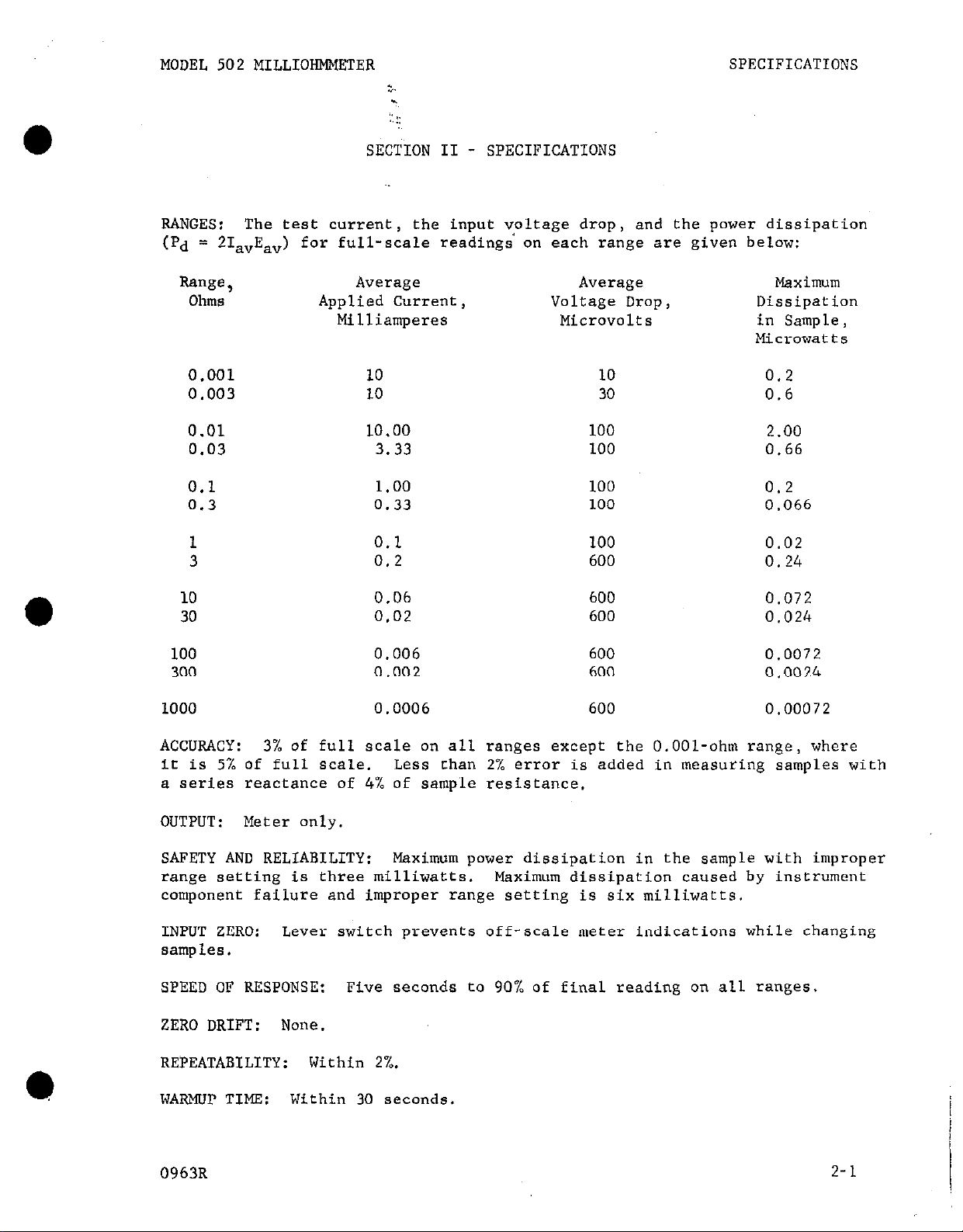
RANGES: The test current,
the input vpltage drop, and the power dissipation
(Pd = 2&E,,) for full-scale readings on each range are given below:
tinge,
Ohms
Average
Average
Applied Current, Voltage Drop,
Milliamperes Microvolts
Maximum
Dissipation
in Sample,
Microwatts
0.001 10
0.003 10
0.01 10.00
0.03 3.33
0.1 1.00
0.3 0.33
1 0.1
3 0.2
10 0.06
30 0.02
100 0.006
300 0.002
10
30
100
100
100
100
100
600
600
600
600
600
0.2
0.6
2.00
0.66
0.2
0.066
0.02
0.24
0.072
0.024
0.0072
0.0024
1000 0.0006
600
0.00072
ACCURACY: 3% of full scale on all ranges except the O.OOl-ohm range, where
it is 5% of full scale. Less than 2% error is added in measuring samples with
a series reactance of 4% of sample resistance.
OUTPUT: Meter only.
SAFETY AND RELIABILITY: Maximum power dissipation in the sample with improper
range setting is three milliwatts. Maximum dissipation caused by instrument
component failure and improper range setting is six milliwatts.
INPUT ZERO: Lever switch prevents off-scale meter indications while changing
samples.
SPEED OF RESPONSE:
Five seconds to 90% of final reading on all ranges.
ZERO DRIFT: None.
REPEATABILITY:
WARMUP TIME:
Within 30 seconds.
Within 2/,.
D
0963R
2-1
Page 6

SPECIFICATIONS
:.
::
BATTERY LIFE: 360 hours minimum. :
MODEL 502 MILLIOHMMETER
BATTERY TEST:
An internal resistance standard is measured in the Battery
Test Position to provide a comple<e check of battery condition and proper instrument operation.
BATTERY COMPLEMENT: Two RM 401R, two RM 42R, one 412, one 413.
TUBE COMPLEi%ENT: One 6418, four 6419.
TRANSISTOR COMPLEMENT: Four 2N1381.
ACCESSORIES FURNISHED:
ligator clips;
CONNECTORS:
one set Klipson adapters; mating connectors.
Amphenol 80C and 80-PC2F receptacles.
Model 5021 Current and Voltage Leads; one set of al-
DIMENSIONS:~ 9 inches high x 6 inches wide x 7 inches deep.
NET WEIGHT: 7-l/2 pounds.
'02648
Page 7
MODEL 502 MILLIOHMMETER
CONNECTIONS
.A.
(1) Lower resistances (less than 3 ohms).
OPERATION
-T
: ::
':sECTION III - o~mm10N
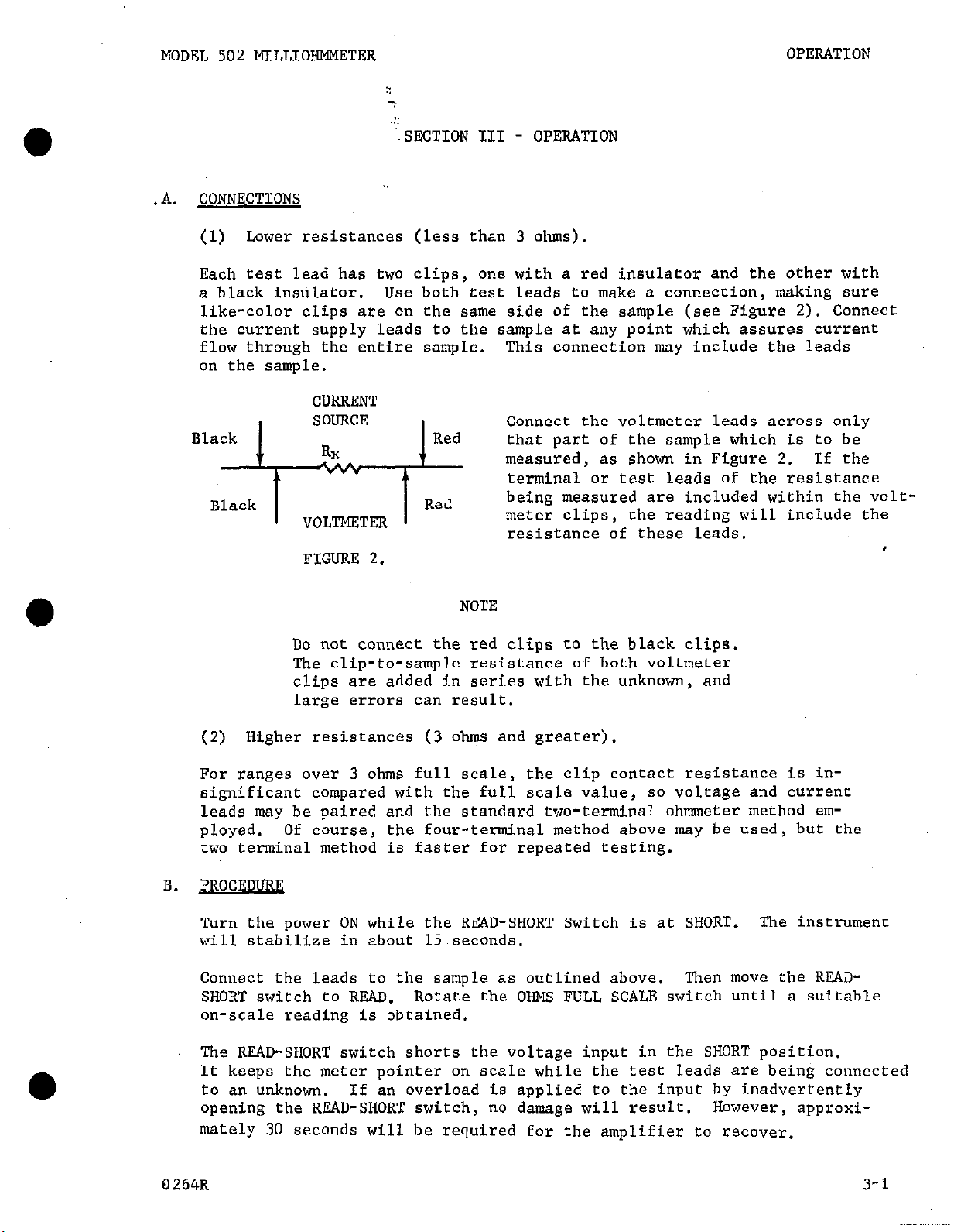
Each test lead has two clips,
a black instilator.
Use both test leads
one with a red insulator and the other with
to
make a connection, making sure
like-color clips are on the same side of the sample (see Figure 2). Connect
the current supply leads to the sample at any point which assures current
flow through the entire sample.
This connection may include the leads
on the sample.
CURRENT
Black
SOURCE
Red
I
RX
Connect the voltmeter leads across only
that part of the sample which is to be
measured, as shown in Figure 2. If the
terminal or test leads of the resistance
Black
I-+
VOLTMETER
Red
being measured are included within the voltmeter clips,
the reading will include the
resistance of these leads.
FIGURE 2.
NOTE
Do not connect the red clips to the black clips.
The clip-to-sample resistance of both voltmeter
clips
are
added in series with the unknown, and
large errors can result.
(2) Higher resistances (3 ohms and greater).
For ranges over 3 ohms full scale,
the clip contact resistance is insignificant compared with the full scale value, so voltage and current
leads may be paired and the standard two-terminal ohmmeter method em-
ployed.
Of course,
the four-terminal method above may be used, but the
two terminal method is faster for repeated testing.
PROCEDURE
B.
Turn the power ON while the READ-SHORT Switch is at SHORT.
The instrument
will stabilize in about 15 seconds.
Connect the leads to the sample as outlined above.
SHORT switch to RF,AD.
Rotate the OHMS FULL SCALE switch until a suitable
Then IIIOW the RRAD-
on-scale reading is obtained.
The READ-SHORT switch shorts the voltage input in the SHORT position.
It keeps the meter pointer on scale while the test leads are being connected
to an unknown.
opening the READ-SHORT switch, no damage will result.
If an overload is applied to the input by inadvertently
However,
approxi-
mately 30 seconds will be required for the amplifier to recover.
0264~
3-l
Page 8

O-ON
MODEL 5tX
MILlJon
:
C.
BATTERY TEST
Before a reading is made, it may be desirable to check overall circuit operation.
TEST and switching the BEAD-SHORT switch to.BEAD. The meter should
reati within 1% divisions of the red line on the meter face marked
BATTERY TEST.
a circuit failure which, in most cases, will be battery failure.
Consult SEmION V ing information.
PRECAUTIONS
On full scale ranges of one ohm and below, the amplifier has sensi-
tivities in the microvolt region and a pass band which includes 60
cps.
magnetic field may give a meter indication.
to avoid such magnetic loops. .Care should also be taken in shielding
critical circuits to avoid 60 cps pickup from electric fields; in
general, however, the electrostatic pickup is not serious at the impedance involved. One way to test for pickup is to remove. the current supply leads with the voltage leads connected to the sample.
If no reading appears on the meter, no pickup is present. If some
reading does occur due to the presence of 60 cps magnetic field, it
may be reduced to a minimum by rotating the meter for minimum pickup.
In any case, the instrument reads correctly above any residual read-
ing.
ence of stray fields with the voltmeter leads shorted, a .003 ohm
resistance being tested will still read ,003 ohms.
the 60 cps signal is superimposed on the 100 cps square wave test
signal.
only the rectified square wave.
Thus, a loop in the voltage leads which encloses any 60 cps
For example, if the 502 reads, say, .002 ohms due to the pres-
Thus the 60 cps signal is not rectified and the meter reads
This is d&e by rotating the range switch to BATI?, -
Failure of-the unit to read within these limits indicates
MAIWPEB4NC.E for battery changes or troubleshoot-
:.
Care should be exercised
This is because
l
Because of the AC technique employed, inductive and capacitive com-
ponents in the test impedance may cause some waveform distortion and
erroneous readings. Series inductive impedance (at 100 cps) less
than 20% of the resistance cause the reading to be less than 2% high.
Shunt capacitive admittance (at 100 cps) less than 6%
ante cause the reading to be less than 2% low, Listed below are the
limiting values of inductance and capacitance to cause 2% error at
full scale on any range:
RANGE
.OOl ohms
.003
.Ol
.03
.1
.3
1.0
1%
30
100
300
1000
MAX SERIES INDUCTANCE
.3 microhenries
.9
3
309
go
.3 millihenries
3 .9
309
90
.3 henries
h¶AX SHUNT CAPACITANCE
1000 microfarad
750 microfarad
mJ
::
7.5
2.5
of the.hiduct-
I
over
I
3-2
0762
Page 9

KODEL 502 MILLIOHMMEEER
It is well to remember that basically, the Model 502 is measuring
the voltage acro& the sample resistance due to current flow in
the sample.
Model 502, no difficulties should be encountered. However, if
other currents are flowing in the sample in addition to the test
current, these currents must be either small compared with the
test current or essentially dc.
in the milliohm region which is carrying more than 50 amperes of
direct current, but even .Ol amperes of alternating current whose
frequency
serious error.
When measuring samples across which a dc voltage greater than about
.05 volts may appear,
with one current lead and another capacitor in series with one volt-
age lead. Use 1000 mfd at a voltage rating sufficient to handle the
dc sample voltage.
So lpng as the sample current is generated by the
The Model 502 will read a resistor
is within the pass band of the amplifier will cause a
a blocking capacitor should be used in series
The setup is shown in Fig. 3.
If this arrangement is to be
used on the ranges below .3
ohm, also include r as shown.
This resistor is to provide
a d.c. return path for the
output transistor, Qk.
OI'FSWITON
Values of r and C are shown below:
Range
.l
.Q
.Ol
.003
.OOl
0264R
2
100
2
10
10
C
1OCOmfd
1000
boo0
LOO0
LOO0
Added error
-1%
-3%
-6%
-6%
-6%
3-3
Page 10

MODEL 502 MILLIOM&!E!VBR
CIRCUIT DESCRIPTION
SECTION IV - CIRCUIT DESCRIPTION
The standard method of measuring resistance assumes that test lead resistance is negligible. When measuring resistances at or below the
level of lead resistance, a more sophisticated approach is required.
The four-terminal method of resistance measurement consists of supply-
ing current from an isolated current generator to the sample, and
measuring the voltage drop across the sample with an isolated voltmeter.
The generator is made to supply constant current regardless of lead
resistance so that no errors occur due to current lead connection,
The voltmeter has large enough input resistance so that the voltage
lead resistance does not cause any error.
Since there is no current
error and voltage error, the resistance is read correctly.
The 502 circuit consists of two parts,
a 100 cps transistor squarewave
generator supplies the current across the sample and the AC microvolt
meter measures the voltage drop.
in ohms on a linear scale.
Refer to the circuit diagram, DR 12189-C.
(1) Square W-ix Generator.
The panel meter is calibrated directly
The 100 cps square wave is generated by
a transistor multivibrator consisting of Ql and Q2. Rlb6 is a symmetry
control which is set at the factory to give a symmetrical square wave.
This adjustment is necessary to insure no change in reading when the
current leads are reversed.
Q3 and Qk serve as a power amplifier.
Transistor Qh acts essentially as a 100 cps switch connecting and disconnecting El across the sample and series resistors Rl32 through
Rllr2.
of the mercury battery voltage,
Due to the fact that the output peak voltage is more than 95%
the change in square-wave amplitude
with change of transistor parameters is very small. B6 supplies a
small negative bias current through R151 to the output transistor to
insure good cut off characteristics,
at a high ambient temperature.
(2) AC Amplifier. 'Ihe ac amplifier is a conventional vacuum tube
voltmeter with meter current feedback. The input signal is matched
to the vacuum tube input by an input transformer on the more sensitive
ranges.
Above 1 ohm, the input transformer is not used.
The input voltage is compared to the feedback voltage through RlOl and
RI02 into the grid of Vl. Vl, V2, V3, Vk, and V5 amplify the error
signal.
supply indicating meter current.
The output voltage is full-wave rectified by Dl and D2 to
The ac current through the meter
and rectifiers flows in R128, R129 or R130 to supply feedback voltage
to the first stage.
The dividers R103 and R126 or R127 allow separate
calibration of the ranges which employ transformer input and the
ranges which do not.
ON BATTERY TEST, the unit is automatically placed on the 1000 ohm
range.
A 500 ohm resistor, Rlk9, is connected into the test position
and the external current and voltage leads are disconnected. Since
battery current drain is essentially the ssme on all ranges, this
test will indicate faulty batteries Immediately by giving a reading
less than normal.
0762
4-1
Page 11

MDDEL 502 MILILO~IMMETER
:.
;;SECTICN V - MAINTENANCE
MAINTENANCE
A.
B.
BATTERIES
Under ncrmal conditions the only maintenance required will be the
replacement of batteries.
screws at the rear and slide the instrument out of the case.
To reach the batteries, remove the four
The
batteries are all located in holders at the top of the instrument.
Bl, supplying the current generator,
and B3, which supplies the
vacuum tube filaments, should have a useful life of about I460 hours
unless the instrument is used continuously on the lowest three ranges.
This may shorten the life of Bl to 360 hours. Bh, which supplies
plate potential to the output tube should last thrcugh about two
changes of Bl and B3.
B2, the bias battery, B5, the plate supply
for the amplifier, and B6, the negative bias for the output tran-
sistor,
should last about two years.
To be certain of always having
fresh batteries, a good practice would be to change all batteries
whenever one of the set needs replacement.
TROUBLE-SHOOTING
If the circuit fails to perform properly and the batteries are found
to be good,
a step-by-step procedure should be followed to discover
the fault.
First check the current supply wave form at the current output termi-
nals. This should be a 100 cps square wave about 1.3 volts amplitude.
Switch to the 1 ohm range so that oscilloscope loading will not affect
the wave form.
If the desired wave form is not present, check the
generator circuit stage by stage. Ql and Q2 are connected as a multivibrator. Q3 and Qk are cascaded emmitter followers which develop
the output current drive.
If the current supply works properly, check the voltage
amplifier.
First compare observed operating potentials with those given in the
Voltage Diagram in this section.
When operating points are all cor-
rect, the amplifier may be checked stage by stage for amplification.
Note that V5 is used to supply current to the meter, and therefore
has a voltage gain of only about one.
The voltage required at the junction between Cl15 and the meter
diodes for full scale deflection is approximstely 0.75 volt RMS.
The Voltage Diagram, DR 12256-4, Circuit Schematic, DR 12189-u and
parts list are included at the back of the manual.
0762
5-l
Page 12

l
MODEL 502 MILLIOHMMETER
.
:L::
S!iCTION 6.
REPLACEABLE PARTS
REPLACEABLE PARTS
6-1. REPLACEABLE PARTS LIST.
ponents of the Model 502 and its accessories.
signation, the part description, a suggested manufacturer, the manufacturer's
part number and the Keithley Part Number.
facturers listed in the "Mfg.
6-2.
the Keithley Part Number,
part. All structural parts and those parts coded for Keithley manufacture
(80164) must be ordered from Keithley Instruments, Inc. In ordering a part
not listed in the Replaceable Parts List,
function and its location.
Service Department, Keithley Instruments, Inc.
camp
HOW TO ORDKR PARTS.
For parts orders, include the instrument's model and serial number,
a.
b. Order parts through your nearest Keithley distributor or the Sales
ampere
Composition
Deposited Carbon
The Replaceable Parts List describes the com-
The List gives the circuit de-
The name and address of the manu-
Code" column are contained in Table 2.
the circuit designation and a description of the
completely describe the part, its
R
PM
Poly
P
ohm ohm
Paper, Paper,
Polystyrene Polystyrene
pica (lO-l2) pica (LO-l2)
metallized metallized
ETB
f
k
M or meg
m
Mfg.
MtF
Mil. No.
MY
Electrolytic, tubular
farad
kilo (103)
mega (106) or megohms
milli (10-3)
Manufacturer
Metal Film
Military Type Number
Mylar
TABLE 1.
Abbreviations and Symbols.
II
”
Var
w
ww
WWVar
micro (10-6) micro (10-6)
volt volt
Variable Variable
watt watt
Wirewound Wirewound
Wirewound Variable Wirewound Variable
0764R
6-1
Page 13

REPLACEABLE PARTS
(Refer to Schematic Diagrani 121891) for circuit designations.)
MODEL 502 MILLIORMMETER
MODEL 502 REPLACEABLE PARTS LIST
BATTERIES
Circuit
Desig.
Bl
B2
B3
,B4
B5
B6
B7
B8
Circuit
Desig.
Cl01
Cl02
Cl03
Cl04
Cl05
Cl06 .OOl uf
Cl07
Cl08 .22 IJ.f
Cl09
Cl10 .OOOl uf
Description
1.3 v mercury
1.35 v mercury
1.3 v mercury
8.4 v mercury
1.35 v mercury
8.4 v mercury
8.4 v mercury
8.4 " mercury
Value Rating
2
Pf
.0022 pf
.0082 pf
.22 !Jf
2
Pf
270 pf
2
Pf
50 "
200 v
100 v
50 v
50 v
100 v
500 v
50 v
50 "
500 v
Mfg. Mfg.
Code Part No.
37942 RM42R
10608 E401
31942 RM42R
10608 El46
10608
10608 El46
10608
10608 El46
~CAPACITORS
Mfg. Mfg.
Type
ETB 37942
Poly 00686
MY
MY
ETB 37942
Mica 84171
Mica 84171
MY
ETB
Mica
Code
84411
84411
84411
37942
84171
E401
El46
Part No.
TC302
663UW-100
601PE
TC302
DM15-102.J
DM15-271.J
601PE
TC302
DM15-1Ol.J
Keithley
Part No.
BA-10
BA-8
BA-10
BA-9
BA-8
BA-9
BA-9
BA-9
Keithley
Part No.
C39-2M
C55-2200P
C38-.0082M
C41-.22M
C39-2M
c21-1OOOP
C21-270P
C41-.22M
C39-2M
c21-loop
Fig.
Ref.
Fig.
Ref. _
Cl11
Cl12
Cl13
Cl14
Cl15
Cl16
Cl17
Cl18
Cl19
Cl20
Cl21
Cl22
6-2
820 pf
.22 wf
2
Pf
.l nf
.1 wf
0.1 uf
1 (If
1 Pf
50 Kf
50 pf
820 pf
22 pf
300 "
50 v
50 v
50 v
50 v
50 v
200 v
200 "
50 I!
50 v
300 v
500 v
Mica
MY
ETB
MY
MY
MY
PM
PM
ETB
ETB
Mica 84171
Mica 84171
84171 DM15-821K
84411 601PE
37942
84411
84411 601~~
84411 601PE
00656 P8292ZN
00656
37942 TC39
37942 TC39
TC302
601PE
P8292ZN
DM15-821.J
DM15-220J
c21-82OP
C41-.22M
C39-2M
C41-.lM
C41-.lM
C41-.lM
CLB-LM
Cl&1M
C39-50M
C39-50M
CZl-820P
c21-22P
0764R
Page 14

MODEL 502 MILLIOHPlMETER
REPLACEABLE PARTS
Circuit
Desig.
Dl
D2
Circuit
Desig.
Jl
---
52
---
Ml
.,:;
Type
DIODES
Number
Silicon lN645
Silicon lN645
MISCELLANEOUS PARTS
Description
Receptacle, Microphone, Voltage
(Mfg. No.~ 80-C)
Plug, Microphone, Mate of Jl
(Mfg. No. 80-M)
Receptacle, Microphone, Current
(Mfg. No. 80PC2F)
Plug, Microphone, Mate of 52
(Mfg. No. 80MCZM)
Meter (O-SO vamp)
Mfg.
Keithley
Fig.
Code Part No. Ref.
01295 RF-14
01295
Mfg.
Code
02660
02660
RF-14
Keithley
Part No.
cs-34
cs-35
Fig.
Ref.
02660 CS-32
02660
80164
cs-33
ME-13
Sl
52
Switch, DPDT, ON (Mfg. No. 830532)
Toggle Switch, READ-SHORT (Mfg.
No. 3003-DL)
s3
Rotary Switch less components,
OHMS FULL SCALE
_--
Tl
Knob Assembly, Ohms Switch
Transformer
Circuit
Desig. Value
RlOl
R102
R103
R104
R105
RlO6
R107
R108
R109
RllO
1Wl
lM0
60 kn
2.2 m
10 MO
100 kfl
22 m
2.2 Mrl
2.2 I%? lO%, l/2 w Comp
10 wl lO%, l/2 w
04009
82389
80164
80164 16323A
80164
RESISTORS
Rating
Type
l%, l/2 w MtF
l%, l/2 w
MtF
Mfg.
Code
07716
07716
Mfg.
Part No.
MECT-8 R53-1M
MECT-8 R53-1M
l%, l/2 w DCb 79727 CFE-15
l%, l/2 w DCb 79727
lO%, l/2 w
lO%, l/2 w
lO%, l/2 w
lO%, l/2 w
Comp
camp
Comp
Comp
01121 EB
01121 EB
01121 EB
01121 EB
CFE-15
01121 EB
Comp 01121 EB
SW-l76
SW-59
SW-57
TR-53
Keithley
Part No.
R12-60K
R12-2.2M
Rl-1OM
Rl-1OOK
Rl-22M
Rl-2.2M
Rl-2.2M
Rl-1OM
Fig.
Ref.
1164R
c
6-3
Page 15

REPLACEABLE PARTS
Circuit
Desig.
Value Rating
5
~XESISTORS (Cont'd)
::::
Mfg. Mfg.
TYPO
Code Part No.
MODEL 502 MILLIOHMMETER
Keithley
Part No.
Fig.
Ref.
0
Rlll
Rll2
R113
R114
R115
R116
R117
R118
R119
R120
R121
R122
R123
R124
R125
R126
R127
Rl28
R129
R130
R131
R132
Rl33
R134
R135
100 kn
22
m
2.2 IQ
2.2 ml
10 I%l
100 kfl
22
Mrl
2.2 MO
2.2 M
10 m
2.2 lm
47
kn
5 kn
5 kn
1.8 kn
1 kn
100 n
s91 n
300 n
1 kn
47 ko
60
n
180 n
600 n
1.8 kn
lO%, l/2 w
lO%, l/2 w
lO%, l/2 w
lO%, l/2 w
lO%, l/2 w
lO%, l/2 w
lO%, l/2 w
lO%, l/2 w
lO%, l/2 w
lO%, l/2 w
lO%, l/2 w
lO%, l/2 w
l%, l/2 w
l%, l/2 w
l%, l/2 w
lO%, 5 w
lO%, 5 w
l%, l/2 w
l%, l/2 w
1%, l/2 w
lO%, l/2 w
l%, l/2 w
l%, l/2 w
l%, l/2 w
l%, l/2 w
camp
01121
EB
Rl-100K
Comp 01121 EB Rl-22M
Comp
Comp
01121
01121
EB
EB Rl-2.2M
Rl-2.2M
Comp 01121 EB Rl-1OM
Camp 01121 EB Rl-100K
Comp 01121 EB Rl-22M
Comp 01121
EB Rl-2.2M
Comp 01121 EB Rl-2.2M
Comp 01121 EB
Comp 01121 EB
Rl-1OM
Rl-2.2M
Comp 01121 EB Rl-47K
DCb
DCb
DCb
wwvar
wwvar 71450
DCb 79727
DCb
DCb
Camp
DCb 79727
DCb 79727
DCb
DCb
79727 CFE-15 R12-SK
79727
CFE-15
R12-5K
79727 CFE-15 R12-1.8K
71450 AW RP3-1K
AW RP3-100
CFE-15
79727 CFE-15
79727 CFE-15
01121 EB
R12-91
Rl2-300
R12-1K
Rl-47K
CFE-15 RlZ-60
CFE-15 R12-180
79727 CFE-15 R12-600
79727 CFE-15
R12-1.8K
R136
R137
R138
R139
R140
R141
R142
R143
R144
R145
R146
R147
Rl48
R149
R150
6
kQ
3 kn
10 kc
30 kn
100 kn
l%, l/2 w
l%, l/2 w
l%, l/2 w
l%, l/2 w
l%, l/2 w
l%, l/2 w
l%, l/2 w
l%, l/2 w
l%, l/2 w
l%, l/2 w
lO%, 2 w
1%, l/2 w
l%, l/2 w
l%, l/2 w
l%,
l/2 w
"Nominal value, factory set.
6-4
DCb 79727 CFE-15 RlZ-6K
DCb
DCb
DCb
79727 CFE-15
79727 CFE-15
79727 CFE-15
DCb 79727
DCb
DCb
DCb
DCb
DCb
wwvar
DCb
DCb
DCb
DCb
79727
79727
79727
79727
79727
71450
79727
79727
79727
79727
CFE-15
CFE-15 RlZ-300K
CFE-15 R12-1M
CFE-15 R12-82
CFE-15 RlZ-3K
CFE-15
WP RP9-1OK
CFE-15
CFE-15
CF&15
CFE-15 R12-1M
R12-3K '.
R12-10K "
RLZ-30K
RlZ-100K
R12-7K
R12-7K
RlZ-3K
RlZ-500
l
1164R
Page 16

MODEL 502 MILLIOHMMETER
RESI'STORS (Cont'd)
REPLACEABLE PARTS
Circuit
Desig.
Value
Rating
TYPO
R151 15 kfi lO%, 112 w Comp
R152 47 kn lO%,
R153
Rl54
210 n l%,
10 MCI
lO%,
l/2 w
l/2 w
l/2 w
Comp
DCb
Comp
Mfg.
Mfg.
Code Part No.
01121 EB Rl-15K
01121 EB Rl-47K
79727 CFE-15 R12-210
01121 EB Rl-1OM
Keithley
Part No. Ref.
TRANSISTORS
Circuit
Desig.
Ql
Mfg.
Number Code Part No. Ref.
2N1381 01295 TG-8
Keithley
2N1381 01295 TG-8
;:
Q4
2N1381
2N1381
01295 TG-8
01295 TG-8
VACUUM TUBES
Circuit
Desig. Number
Mfg.
Code
Keithley
Part No.
Vl 6419 81453 EV-CK6419
v2 6419 81453 EV-CK6419
v3 6419 81453 EV-CK6419
v4 6419 81453 EV-CK6419
v5 6418 80164 EV-6418-1
Fig.
Fig.
Fig.
Ref.
FURNISHED ACCESSORIES
Mfg.
Description
Two Alligator Clips, red
Two Alligator Clips, black
Two Miniprod Adapter Tips, red
Two Miniprod Adapter Tips, black
~~~~Model 5021 Voltage Lead, includes
.Plug, Microphone
.Phone Tip, Red
.Phone Tip, Black
Code
83330
83330
08811
08811
80164
02660
83330
83330
"g<Model 5021 Current Lead, includes 80164
.Plug, Microphone
02660
.Phone Tip, Red 83330
*Phone Tip, Black 83330
>wcModel 5021 is a set of current and voltage leads.
Mfg.
Part No.
Keithley
Part No.
304 AC-3R
304
33-160
33-162
80-M
AC-3B
PP-3R
PP-3B
cs-35
237 PP-2R
237 PP-2B
80MC2M
237
237
cs-33
PP-2R
PP-2B
1164R
6-5
Page 17

REPLACEABLE PARTS
MODEL 502 MILLIOHMMFXER
:,,
10656 Aerovox Corp.
,. .
New Bedford, Mass.
10686 Film Capacitors, Inc.
New York, N. Y.
11121 Allen-Bradley Corp.
Milwaukee, Wis.
11295 Texas Instruments, Inc.
Semi-Conductor-Components Division
Dallas, Texas
,266O Amphenol-Borg Electronics Corp.
Broadview, Chicago, Illinois
j4009 Arrow-Hart and Hegeman Electric Co.
Hartford, Corm.
)7716 International Resistance Co.
Burlington, Iowa
)8811 G-C Electronics Co., Inc.
Camden, N. J.
10608 Union Carbide Corp.
New York, N. Y.
37942 Mallory, P. R., and Co., Inc.
Indianapolis, Ind.
71450 CTS Corp.
Elkhart, Ind.
75042 International Resistance Co.
Philadelphia, Pa.
79727 Continental-Wirt Electronics
Corp.
Philadelphia, Pa.
80164 Keithley Instruments, Inc.
Cleveland, Ohio
81453 Raytheon Co.
Industrial Components Div.
Industrial Tube Operation
Newton, Mass.
82389 Switchcraft, Inc.
Chicago, Ill.
83330 Smith, Herman H., Inc.
Brooklyn, N. Y.
84171 Arco Electronics, Inc.
Great Neck, N. Y.
84411 Good-All Electric Mfg. Co.
Ogallala, Nebr.
TABLE 2.
Code List of Suggested Manufacturers.
for Manufacturers, Cataloging Handbook H4-1.)
(Based on Federal Supply Code
6-6
1164R
Page 18

1:
t
Page 19

. .
.c
Page 20

:.
:.
iI
!:
Page 21

MODEL 502
VOLTAGE C”ARS
1.3v.
OV.
.63 v.
9.5”.
18.5 M
I
Page 22

Page 23

Keitlhley InWumentn. Inc./26775 Aurora Road/Cleveland, Ohio 44139/(216) 246.04CWTelex: 96.5469
Kaitblay Instruments GmbHIHe~9lholsrrasse 5/D.S0@3 Munchsn 7O/(OS9) 714.40.65/Telex: 521 21 SO
Keith@ Instrummts.
K.ithl.y Inst”m,mt. SARU44. Rue Anal& France/F-91 12, Palaiseau Cedsx/O, -014.22.06,Teler ,942, 204198
Ltd./l. Bouhon Road/GB.Resdinp. Berkshire RG2 ONW(0734) 86 12 07
 Loading...