

Page 1

Page 2

WARRANTY
Keithley Instruments, Inc. warrants this product to be free from defects in material and workmanship for a period of 1 year
from date of shipment.
Keithley Instruments, Inc. warrants the following items for 90 days from the date of shipment: probes, cables, rechargeable
batteries, diskettes, and documentation.
During the warranty period, we will, at our option, either repair or replace any product that prows to be defective,
To exercise this wammty, write or call your local Keithley representative, or contact Keithley headquarters in Cleveland, Ohio.
You will be given prompt assistance and return instructions. Send the product, transportation prepaid, to the indicated service
facility. Repairs will be made and the product returned, transportation prepaid. Repaired or replaced products are warranted for
the balance of the original warranty period, OT at least 90 days.
LIMITATION OF WARRANTY
This warranty does not apply to defects resulting from product modification without Keithley’s express written consent, or
misuse of any product or part. This warranty also does not apply to fuses, software, non-rechargeable batteries, damage from
battery leakage, 01 problems arising from normal we.a~ or failure to follow instructions.
THIS WARRANTY IS IN LIEU OF ALL OTHER WARRANTIES, EXPRESSED OR IMPLIED, INCLUDING ANY
IMPLIED WARRANTY OF MERCHANTABILITY OR FITNESS FOR A PARTICULAR USE. THE REMEDIES PROVIDED HEREIN ARE BUYER’S SOLE AND EXCLUSIVE REMEDIES.
NEITHER KBITHLEY INSTRUMENTS, INC. NOR ANY OF ITS EMPLOYEES SHALL BE LIABLE FOR ANY DIRECT,
INDIRECT, SPECIAL, INCIDENTAL OR CONSEQUENTIAL DAMAGES ARISING OUT OF THE USE OF ITS
INSTRUMENTS AND SOFTWARE EVEN IF KEITHLEY INSTRUMENTS, INC., HAS BEEN ADVISED IN ADVANCE
OF THE POSSIBILITY OF SUCH DAMAGES. SUCH EXCLUDED DAMAGES SHALL INCLUDE, BUT ARE NOT LIMITED TO: COSTS OF REMOVAL AND INSTALLATION, LOSSES SUSTAINED AS THE RESULT OF INJURY TO ANY
PERSON, OR DAMAGE TO PROPERTY.
Keithley Instruments, Inc. - 28775 Aurora R
Page 3

Model 486 Picoammeter
Model 487 Picoammeter/Vokage Source
Instruction Manual
01990, Keithley Instruments, Inc.
All rights reserved.
Cleveland, Ohio, U.S.A.
Fourth Printing, August 2000
Document Number: 486-901-01 Rev. D
Page 4
Manual Print History
The print history shown below lists the printing dates of all Revisions and Addenda created for this manual. The
Revision Level letter increases alphabetically as the manual undergoes subsequent updates. Addenda, which are
released between Revisions, contain important change information that the user should incorporate immediately into
the manual. Addenda are numbered sequentially. When a new Revision is created, all Addenda associated with the
previous Revision of the manual arc incorporated into the new Revision of the manual. Each new Revision includes
a revised copy of this print history page.
Revision C (Document Number 486-901-01)
Revision D (Document Number 486-901-01).
............................................. December
................................................. August 2000
1991
Page 5

BESCHEJNIGUNG DES HERSTELLERS/IMl’ORTEURS
Hiermitwirdbescheinigt,(daS)/dasMODEL 486 PICOAMMETER AND MODEL 487 PICOAMMETER/
VOLTAGE SOURCEinUbereinstimmungmitdenBestimmungenderVfg1046/1984funksntstortist.DerDeuk~en
Bundespost
Eiihmg der Bestimmungen eingeraumt.
Die Einhaltung der betreffenden Bestimmungen setzt vordus, dag, (da& geschirmte Mt$leitungen venvendet werden.
Fur die Beschaffung richtiger Me~leitungen ist der Betreiber verantwortlich.
DIESES GERAET WURDE SOWOHL ElNZELN ALS AUCH IN ElNERANLAGE, DIE EINEN NORMALW
ANWENDUNGSFALL NACHBILDET, AUF DIE EINHALTUNG DER FEN
GEPRUEFT. EST IS JEDOCH MOEGLICH, DASS DIE
UNGUENSTIGEN UMSTAENDEN BEI ANDEREN G ERAETEKOMBJNATIONEN NIGHT EINGEHALTEN
WERDEN. FUER DIE EINHALTIJNG DER FUNK-ENTSTOERBE GEN SEINER GESAMTEN ANLAGE,
IN DER DlESES GERAET BETRIEBEN WlRD, IST DER B?ZlXEZBER VERANTWORTLICH.
wurde
das Inverkehrbringen dieses Gerates angezeigt und die Berechtigmg ZUI Uberprufmg der Serie auf
FUNK-ENTSTOEXB -GEN IJNTFX
Keithley Instruments, Incorporated
CERTIFICATE BY MANUFACTURER/TMPORTER
ThisistocertlfythattheheMODEL
SOURCE isshielded againstadiointerferenceinaccordancewiththeprovisions ofVfglO46/1984. TheGermanPostal
Services have been advised that this device is being put on the market and that they have been given the right to inspect
the series for compliance with the regulations.
Compliance with applicable regulations depends on the use of shielded cables. It is the user who is responsible for prycuring the appropriate cables.
THIS EQUlFMENT HAS BEEN TFSTED CONCERNING COMPLIANCE WITH THE RELFVANT RFl PROTECTION REQUIREMENTS BOTH lNDMDUALLY AND ON SYSTEM LEVEL (TO
TION CONDlTIONS). HOWEVER, IT IS POSSIBLE THAT THESE RFI RBQCERTAIN UNFAV0RABL.E CONDlTIONS IN OTHER INSTALLATIONS. lT IS THE USER WHO IS RESPONSIBLE FOR COMX’LIAN
CE OF HIS PARTICULAR INSTALLATION.
SIMULATE NORMAL OPERA-
ARENOTMETUNJXR
Keithley Instruments, Incorporated
Page 6

Page 7

Safety Precautions
The following safety precautions should be observed before using
this product and soy associated instrumentation. Although some inmument~ and accessories would normally be used with non-hazardous voltages, there are situations where hazardous conditions
may he present.
This product is intended for use by qualified personnel who recognize shock hazards and am familiar with the safety precautions mquired to avoid possible injury. Read the operating information
carefully before using the product.
The types of product users are
Responsible body is the individual or group responsible for the use
and maintenance of equipment, for ensuring that the equipment is
operated within its specifications and operating limits, and for ensuring that operators are adequately trained.
Operators use the product for its intended function. They most be
trained in electrical safety procedures and proper use of the instmment. They most be protected from electric shock and contact with
hazardous live circuits.
Maintenance personnel perform routine procedures on the product
to keep it operating, for example, setting the line voltage or replacing consumable materials. Maintenance procedures are described in
the manual. The procedures explicitly state if the operator may perform them. Otherwise, they should be performed only by service
persomlel.
Service personnel are trained to work on live circuits, and perform
safe installations and repairs of products. Only properly trained service personnel may perform installation and service procedures.
Users of this product most be protected from electric shock at all
times. The responsible body must ensure that users are prevented
access and/or insulated from every connection point. Io some cases,
connections must be exposed to potential human contact. Product
users in these circumstances most be trained to protect themselves
from the risk of electric shock. If the circuit is capable of operating
at or above 1000 volts, no conductive part of the circuit may be
exposed.
As described in the International Electrotcchnical Commission
(IEC) Standard IEC 664, digital multimeter measuring circuits
(e.g., Keitbley Models I75A. 199, 2000,2001,2W2, and 2010) are
Installation Category II. All other instruments signal terminals are
Installation Category I and most not be connected to mains.
Do not connect switching cards directly to unlimited power circuits.
They are intended to be used with impedance limited sources.
NEVER connect switching cards directly to AC mains. When connecting sources to switching cards, install protective devices to lim-
it fault cwrent and voltage to the card.
Before operating an instrument, make sore the line cord is connectcd to a properly grounded power receptacle. Inspect the connecting
cables, test leads, and jumpers for possible wear, cracks, or breaks
before each we.
For maximom safety, do not touch the product, test cables, or any
other instruments while power is applied to tic circuit under test.
ALWAYS remove power from the entire test system and discharge
any capacitors before: connecting or disconnecting cables or jompen, installing or removing switching cards, or making internal
changes, such as installing or removing jumpers.
Exercise extreme caution when a shock hazard is present. Lethal
voltage may he present an cable connector jacks or test fixtures. The
American National Standards Institote (ANSI) states that a shock
hazard exists when voltage levels greater than 3OV RMS, 42.4V
peak, or 60VDC are present. A good safety practice is to expect
that hazardous voltage is present in any unknown circuit before
measuring.
Do not touch any object that could provide a cormot path to the
common side of the circuit under test or power line (earth) ground.
Always make measurements with dry hands while standing on a
dry, insulated surface capable of withstanding the voltage being
measured.
Page 8
The instrument and accessories must be used in accordance with its
specifications and operating instructions or the safety of the equip-
ment may be impaired.
The WARNING heading in a manual explains dangers that might
result in personal injury or death. Always read the associated information very carefully before performing the indicated procedure.
Do not exceed the maximum signal levels of the instruments and accessories, as defined in the specifications and operating infonna-
don, and es shown on the instrument or test fixture panels, or
switching card.
When fuses are used in a product, replace with same type and rating
for continued protection against tire hazard.
Chassis connections must only be used as shield connections for
measuring circuits, NOT as safety earth ground connections.
If you are using a test fixture, keep the lid closed while power is applied to the device under test. Safe operation requires the use of a
lid interlock.
Ifa@ screw is present, connect it to safety earth ground using the
wire recommended in the user documentation.
Then
fer to the operating instructions located in the manual.
-Ibe A
sure 1000 volts or more, including the combined effect of normal
and common mode voltages. Use standard safety precautions to
avoid personal contact with these voltages.
symbol on an instmment indicates that the user should E-
symbol on an instrument shows that it can source or mea-
The CAUTION heading in a manual explains hazards that could
damage the instrument. Such damage may invalidate the warranty.
Instrumentation and accessories shall not be connected to humans.
Before performing any maintenance, disconnect the line cord and
all test cables.
To maintain protection from electric shock end tire, replacement
components in mains circuits, including the power transformer, test
leads, and input jacks, must be purchased from Keithley Instnmenu. Standard fuses, with applicable national safety approvals,
may be used if the rating and type are the same. Other components
that are not safety related may be purchased from other suppliers as
long as they are equivalent to the original component. (Note that se-
lected parts should be purchased only through Keithley Insrmments
to maintain accuracy and functionality of the product.) If you are
unsure about the applicability of a replacement component, call a
Keithley Instruments office for information.
To clean an instrument, use a damp cloth or mild, water based
cleaner. Clean the exterior of the instmment only. Do not apply
cleaner directly to the instrument or allow liquids to enter or spill
on the instrument. Products that consist of a circuit board with no
case or chassis (e.g., data acquisition board for installation into a
computer) should never require cleaning if handled according to instructions. If the board becomes contaminated and operation is affected, the board should he returned to the factmy for proper
cleaning/servicing.
Rev. IO/99
Page 9

SAFETY WARNINGS
hstmnentation and accessories should not be connected
to humans.
The following prec.~tions should be observed before using Model 4&X/487. Refer to main manual for detailed
safety information and complete operating instructions.
The Model 486/487 is intended for use by qualified personnel who recognize shock hazards snd are familiar
with the safety precautions required to avoid possible injury. Read over the instruction manual carefully before
using the ins+nunent.
Before operating the instrument, make sore the line cord
is connected to a properly grounded power receptacle.
Exercise extreme caution when a shock hazard is present.
Lethal voltages may be present on the test fixture or the
Model 487 output jacks. The American National Standards Institute WNSI) states that a shock hazard exists
when voltage levels greater than 30V RMS or 424V peak
are present. A good safety practice is to expect that hazardo~voltageispresentinany~o~cirmitbefore
measuriug.
Inspect the connecting cables, test leads, and jumpers for
possible wear, cracks, or breaks before each use.
Maintenance should only be performed by qualified
service personnel. Before performing any maintenance,
disconnect the line cord and all test cables from the instrument.
CONTROL SUMMARY
DISPLAY INTENSl7Y: Selects normal/dim/off display.
LOCAL: Places unit in local and restores front panel key
opergion.
MENU: Use with the knob or cursor keys to configure the
following menu items; data store, data recall, I-limit
(Model487), integration, IEEE-488 bus Coos or talk-only),
defaults, self&t, debug, calibrate, and V-Source calibrate
(Model 487 only).
SHIFT EXIT:
ZERO CHECK Allows check of offsets, and must be disabled to obtain an input signal measurement.
SHIFT CORRECT: Performs automatic zero correction to
null insment offsets.
FILTER: Enables or disables the selected filter(s).
&ik MENLJ or trigger SETUP.
Formadmumsafety,donot touchtheModel487connections, teat fixture, test cables or connections to any other
instruments while power is applied to the circuit under
test. Turn off all power and discharge all capacitors before connecting or disconnecdng cables or jumpas. Also,
keep the test fixture lid dosed while power is applied to
the device under test. Safe operation requires the use of
the lid interlock.
Do not touch any object which could provide a current
path to the common side of the &cuit under test or
power line (earth) ground.
Do not exceed the maximum signal levels of the in&ument, as shown on the rear panel and as defined in the
specifications and operation section of the instnxtion
manual.
Connect the - screw of the test fixture to safety earth
ground using #I8 AWG or larger wire.
0
SHIFTFILTER SELECT: Use with knob or cursor to select
the f&r(s); digital, analog, or digital + analog.
REL Use to establish a baseline using the displayedreading.
V RANGE A: Use range keys to select a lower or higher
current range.
SHm AUTO RANGE: Use to enable/disable autorange.
SETLIP: Use with knob or cursor keys to con@ure the fol-
lowingtriggersetupitems;triggermode,triggerinterval,
trigger delay, and bigger source.
OPERATE: Places V-Source of Model 487 in operate or
standby.
TRIGGEE Press to trigger a reading or start the data
store.
PRESET: Toggles between two preset V-Source values
(Model 487 only).
SHIFT OHMS cV/Ij: Press to select V/I Ohms.
Page 10
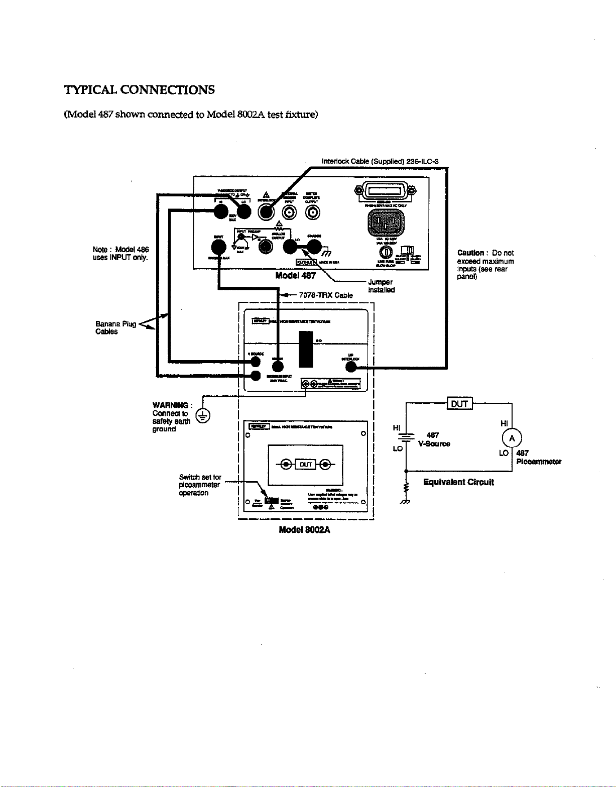
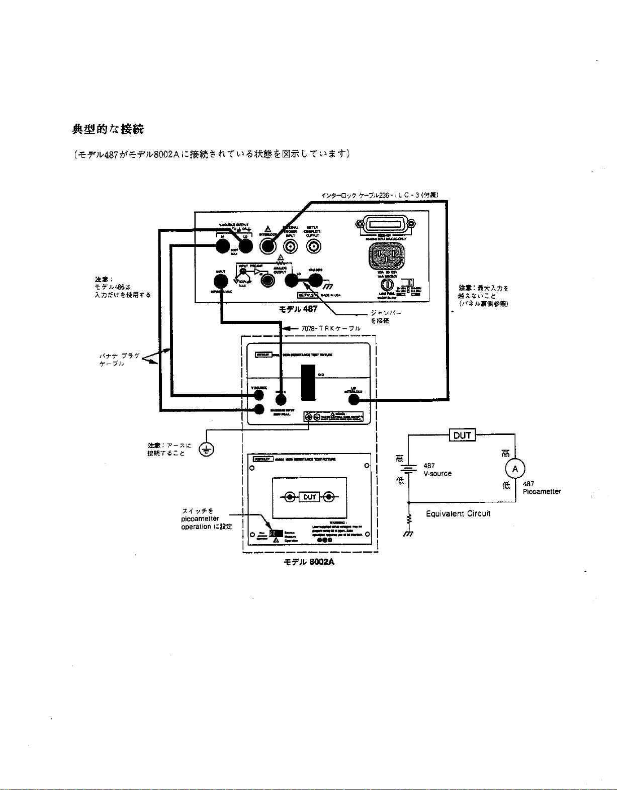
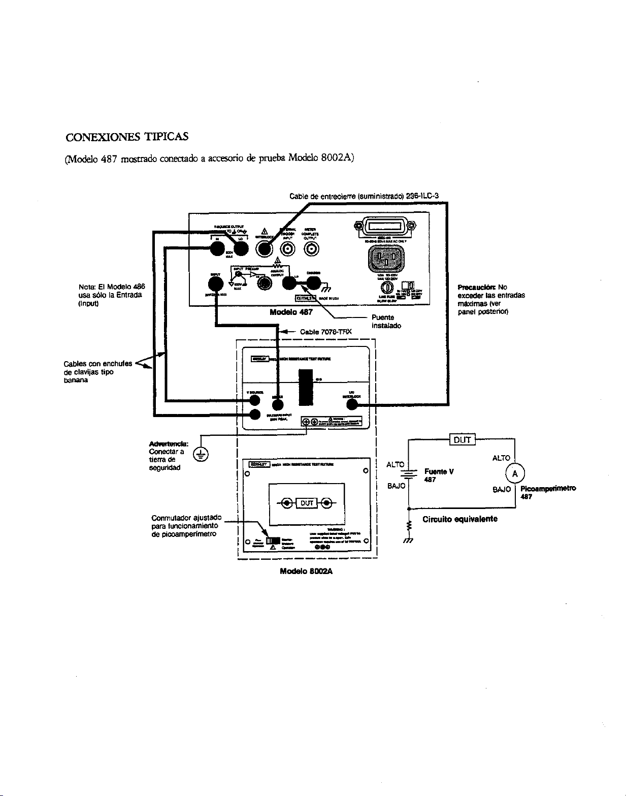
TYPICAL CONNECTIONS
(Model 487 shown connected to Model 8CKQA test fixture)
Model 8002A
TL
- 487
“-so”rcw
LO
T
Equivalent circuit
i
HI
A
LO 487
Plcoammeter
0
Page 11

CONSIGhTS DE SECURITF!
RESUME DES COMMANDES
n faut prendre les pr&autions suivames avant d’wiliw les me
d&les 4861487. Veuilk vow reporter au manuel principal qui
comiem tous les remeignemenu sur les consigns de skcuritt
ainsi qw les clirectiva d’utilisation.
LE mod&s 4861487 soot destiks a des spkialistes cotxcients
des dangers de secow &cuique et co-t les mesur-es de
prkntion g prendre pour eviter tout risque de blesnuex. Veuilez lire attentivemeot ce manxl avant d’utiliser l’insmtment.
V&&z., avant d’utiliser I’instmment, que le cordon soit branchC
SW une prise convenablement reli& B la term.
Redoublez de pr&autions lorsqu’il existe tm risque de secow
&cttique. Des tenkn.5 moxtelks risqueot d’&.e pksentes au
n&au du circuit d’essais ou des j&s de sortie du mcckle 487.
selon l’instintt amticain des normes (ANSI), il e&e ml risque
de secousse &cuique lorsque le nivem de la tension d+asse 30 V
efficaces ou 42,4 VC de tension c&e. If esf toujours prudent
de consid&r.er qu’une tension dangerewe est prknte dam
tout circuit incomm avant dkffectua une mesure.
Examinez l’itat da cslbles de cotmexion, des fils d’& et des
cavaliers pour s’asurer qu’ils ne prksentent ni &g&B d’usure, ni
aaqlxlures, ni fissures want chaqlle essai.
Pour un maximum de s&m-it& ne touchez pas les fik du mod&
487,
le circuit de mesure, les &les d’essais, ni les braochemenn
a attam mm inmument lotxque le circuit en mm-s d’essai est
at.5 tension. Coupe2 l’alimentation en comam et d&barge2 tous
les con~teun avant de braocher ou de &brancber d-es c5ble-s.
ll faut +akment veiller A ce que le couvercle du circuit de mesure
d’mais mte fermi pendant que l’appareil en cow-s d’essai est
sous tension. Le vermuillage du couvercle et nkssaire pour tm
foIutiomlemem en tome skmi~.
Ne touchez aucun objet susceptible de fomnir tm chemin conductem vers le c&k commun du tit en cows d’essai ou la terre (masse) &I circuit d’alimeotxion.
Ne .L+SS.Z pa 1s nivemx
malt 6gurant sur le pamleau an&e et d&is a” chapitre caratt&istiques et folxxionnement de la notice d’utilisatiotl.
Fiiezlavis Q dudrruitd’eyaisalaterregl’aided’un~de
jauge 18 AWG ou plus gms.
lnsrmmena et accgsoiTes
somles
lo ne faut faire edcuter la maintenance que par du penonnel Spe
cialisd. Dkbranchez le cordon d’alimentation et tous les Cgbler
d’esais de I’instmment avant d’effecmer tme quelconque o@ra
don de maintenance.
maximum de sigoaux de l’iosav
ne dokent pas be oxcord& g des per-
lNZBX!SIl?E D’AFHCHAGE (DISPLAY lNTEN.SITyI :
Pennet de s&ctiomw : normaL&.ible!pas d’affichage.
COMMANDE DIRECZZ (LOCAL) :
r-em l’appareil et remet en foxtionnement les touches du
panneau d’affichage.
MENU (MENU) : s’udise avec le bouton on les touches du NTsew pour configurer Ia &mems suivants du menu : mise en
m&mire de dam&, rappel de doonkes, limite I (tooMe 487),
int&mion, le bus EEE-488 (voie de tmmmksion ou communication seulement), v&m par d4fam, contrble automatique, mise
au point, balormage et &lomage de la source de tension V
(mod&
487 seulement).
TOUCHE MAJUSCUJX - SORllE (SHIFTEXI’IJ :
de soti du MENU oli de d&lencher I’INSTALLATION
@ETup).
lrwFCATIoN DU ZERO (ZERO CHECK) :
ficatim cles d4cdam et doit &re invalid& pour obtenir le signal
normal de sortie.
Permet de commander di-
Permet
Pet-met la v&i-
TOUCHI? MAJUSCULE - CORRECTION (SHlFT COR-
RECTJ : R&l&e la mix e z&o automatique pour am-&r les
c2kcalaga des instruments.
TOUCHF MAJUSCULE - SELECTION DU FLXRE
(SHIFT FILTER SELECT) : s’urilise avec le bouton ou le curseu pour selectiotmer le(s) filtfe(s); mm&iqtx, analogique 0”
numkique + analogique.
V RANGE A (RANGE) :
selectiomler lme gamme plus basse ou plus haute.
Utilkez les touches de gamme pcnu
TOUCHE MAJ(ISCULE - GAMME AUTOMAnQUE
(SHIFi- AUTO RANGE) : s’wilis pour valider ou irmlickr
mode gamme automatique.
IhSTALLATION (SETUP) : s’unlise avec un bouton ou les
touches c,mems pour configurer le ciichchmat des systemes
de cklenchemem suivaoa : mode &clenchement, intervalle de
Wenchement, retard de dklencbemem et source de dkclencbe
*em.
FONCli’ONNEMtWT (OPERA=) : Met la source
V du ma&k 487 en fonaioonement ou en veik.
DECLWCI.zW@h’T (TRIGGER) :
tme lecture ou d&arer la mix en memoire des doom&.
PREREGLAGE (PRESEV :
sources de t&on V (mod& 487 seulement).
Pa-met de ba.scuk entre V&LIE de
Appuyez pour d-klmcber
de tension
TOUCHE MAJUSCULE - OHMS (SHI3T OHMS V@ :
puyez pour sactiomler v/l ohms.
k
Ap
Page 12
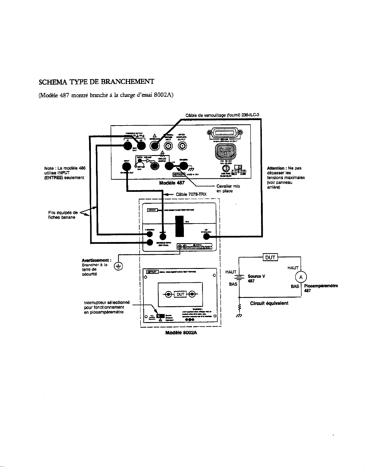
SCHEMA TYPE DE BRANCHFNENT
(Mcd+.le 487 mom& branch& P Ia charge d’csai 8002A)
Cimit dquivalent
k
DUT
Page 13

SICHERHEITSHINWEISE
KONTROLLBEGRIFF’E
Vor dem Gebrauch des M&ells 4861487 soIlten Sie folgende
Vorkehrungen &fen. Wenden Sie sich hinsichtlich ausfiihrlither Sicherheitsinformationen und vollst&~diger Bedienungsm
weisungen an das Haupthandbucb.
Dar M&U 4861487 is fiir den Gebrauch durch qu&izierts
Personal ausgelegt, das eine Stromwhkggefahr erkenm und mit
da Sicherheitworkehmngehrungen vertraut ist, die zur Verhinderung
einer mbglicben Verletzung pea&n we&n miisxn Vor den
G&much des G&&s sollten Sie da Anweisungshandbuch sorgfag lesen.
Vor Uxtriebnabme des G&es soilten Sic da-auf achten, da&
da Suomkabel mit einer vo~ig gee&ten Suomquelk
verbunden is.
S&e Suomvhlaggefabr best&n, so g&en Sie mit Xuiulsenter
Vosicbt var. Auf der Tatvonichtung c&r den Amcbliisxn des
Modells 487 kijnnen t&&he Sparmungen vorhanden sein. Das
American National Standard Institute (ANSQ weist damuf bin,
da& eine Suomschlagg~ dam besteht, wenn die SFannungswene h6her als 30 Volt RMS oder 42,4 Volt Spia&is@.mg be
uagen. Eine gute Sicherhei@nahme ist die Vermutnng, da& in jedem unbekannten Stromkreis vor dem MS
sen eine g&liche Spamung vorhanden is.
PrJfen Sie vor jeder
md
Briicken auf m&$icbe Abnutnmg, Rise cder Briiche.
Beriibren Sie LUT maxim&n Siiherheit keine Amcbiiisse, Priifvonichtungen, Priifkabel ode Verbindungen zu anderen Ge
men, w&rend der zu priifende S~omkreis mit Strom versorgt
wird. Sellen Sic den Strom ab und entladen Sic alle Kondensatmen, bevor Sic K&l c&r Briicken an&Ii&n oder trennen.
H&en Sic auBer&m den Testmscbl&deckel ggchlos~en, withrend das zu priifende G&t mit Strom versorgr wird. Eine sichere
Bedhung bedeutet die Benutzung e&s Deckeischlosses.
Baiihrm Sie keinen Gegastan& der eine Stmmleitung LUT ge
meinsamen site des zll priifendsI stmmkreises cder deI Stromkatebnaw dare&.
iiberschreiten Sic nicht die auf da Riickseite des G&&es verge
gebenen HlichstwMe, die auBer&m ix-n Kapitel Tech&&e
Dawn und Beuieb da Bediemmgshandbuchs bschrieba sind.
V&inda Sie die 0 = Scbraube des Pr&xchl- mit Hilfe
eims Nr. 18 AWG c&r gr&ren Kabels mit da Masse.
Geme und Zubehtir s&a nicbt an Mahen an&+scblassen
werden.
Die Wammg s&e nut durch qualifiziertes Penxnl vorgenommen werden. Vor einer Wammg des Get-&s solken das Stromk&l und alle anderen Priifkabel van diem geuennt werden.
BmuQung
alle Verbindungskabel, Priif?abel
AN.ZIGEHELLIGKEIT (DISPLAY Ihfl.ENSI~):
Anzeige normaUabgedunkeltiaus.
LOKAL (LOCAL):
Frontabdeckungstastenfunkdon wieder her.
Genii (MENlJ: Venvenden Sie diesen B&hl nsammen x-nit
den Knopf- c&r C~rtasten, um f&en& Meniidaten abzur&n: $&hem der Dawn (data store), Abmfen der Data (data
red), IGrenrwert (Rimit) (Mcddl 487), Integlatioxl (mtegradon), IEEE-488 VielfKhlenmg (nur Vielfachleitung a.&
Gqdch), Nullstellungen (~dts), Sehtpriifung (seXtest), Emstijren (debug), Eicben (calibrate) und Spannungs4u~~tichu,-,g
(V-Sowc~ calibrate) (nw MC&II 487).
SHIFT EXIT (SHIFT EXIZJ: Bender, ME& c&r auslijsen
SETUP.
NULL?‘RiiFUNG (ZERO Ch!ECK):
Abweicbungen und mui3 zum Erhaltm einer F.ingabesig-
nabnaung unterbrwhen we&a.
SHFi- CORRECT (SHLFT CORRECT Fiibrt automatische
Nullkorrektur ZUT Nulhllmg der Ger&abwichungen durcb.
FZLTER (RZERJ: Bet&&t oder unterbricht da?&& gewiihlte(n)
Filter.
Bringt Geriit in Local-Modus und stellt
Em@licbt Priifung der
Wtit
SHIFi-FLLTER WAHL (.SHL=TRLll?R SELECn: Venvenden
SiediesenBefeblr
ter zu bestimmm; digital, analog cder digital und analog.
REL (R.&C): Verwada Sie diezen Befehl, urn linen Gnmthvert
fiir die angezeigte Ablesung faulegen.
V BJZREICH A (RAh’GE):
urn e&n nkdrigeren oder h&eren Strombereicb festzulegen.
SHIFT AUTO-BEREICH (SHIFT AUTO RANGE):
den Sie diesen B&l, um den AutoBaeicb (autorange) Befehl
zu aktividd.
AUIT7ELLVNG (SEW): Verwenden Sie diesen Befehl zusammen mit den Knopf- odet Curscnasten zur Kon&uration folgender TrQeritnp~ufsteUun~; Trig&mndus, TriggerintervaIl, Tti~emerr6genmg und TriggerqueUe.
BETRlEE(OPERATE):
487 in Be&b c&r Standbymcdu.
TRIGGER (ZWGGER): Betitip Sic dige Taste, urn eine Ab
lesung cder die speichaung “on Lktm awdiisen.
usammen nit Kxpf c&r Cunor, urn die Fil-
Benutzen Sie diese Bereichsmsen,
Verwen-
Bringt Spannungsquelle de Mcdells
VORGABE (PREFl-: Schdtet zwischm zwti vor~e&enen
Spannm~uellenwerten (mu Modell487).
SHIFT OHM (V/I) (SHIFT OHMS V7Ij:
Taste, urn V/I Ohm zu betimmen.
Driicken Sie dies=
Page 14
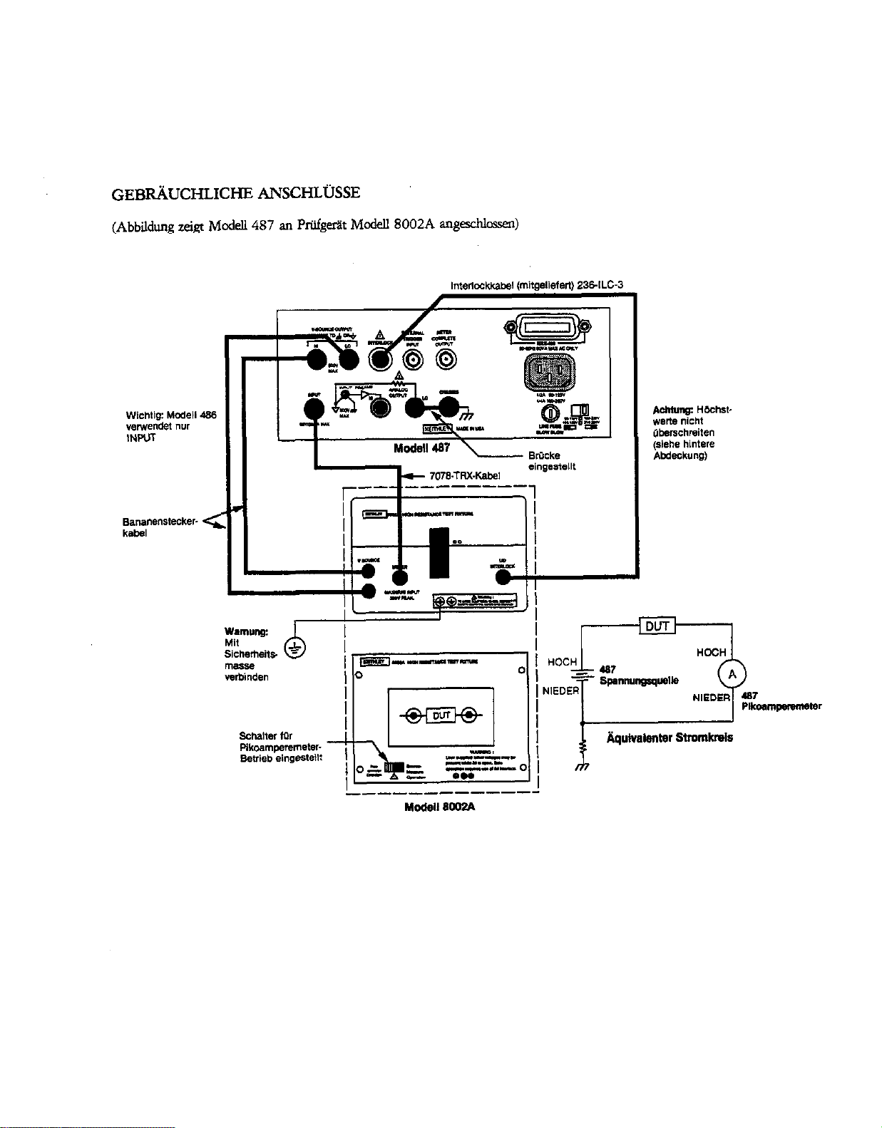
GEBRiiUCHLICHE ANSCHLijSSE
(Abbildq zeigt McdeU 487 an Priifgeriit Mcdell8002A “I@chlossen)
I
T
I
Page 15
NORME DI SICUREZZA
IUASSUh’TO DJ3 COMANDI
Le name di sicurezza segwnd dew10 mere mervate prima di
ware U modello 4861487. Fate riftiento al rnmuaie principale
per “ngsioti demgu suue norme di sicurn e le is”lKio”i per
I’uro.
II modello 4861487 e’ stat0 progetrato ad uo di pe~nale
qlmlificato, a co”cscenza CM Ii&i0 di sccma elemica ed awnte
-ma’ co” le preca”z.ioti necemarie per evimre ogni da”“0
possibiie a persane e case. Leggem attentamente quest0 “ranwale
prima di udliuare lo sml”lento.
Prima di far fu”zionare lo sml”lento, &%sic”ratevi the il cordone
elemico sia appmmamente adlegato ad una press di alimentazione CO” la mesa a terra ccuretm.
Prrstate esn-ema atten7io”e in situazioni in cui e’ prwnte il
rischio di sccaa elletrica sulk3 -ento 0 “el cimdto di prow%
in qtmnto e’ p&bile the vi si rilevino tensioni considerate letah
imprerse dall’utente. L‘ANSI (American National Standard Insti~te)riconmceurischiodismssaelemicdinpresenraditensioni di picco ma&xi di 30V RSM o 42.4V. E’ buona “orma
coti* presenti tensio”i peric&se i” ogni circllito elemico
slxmxiuto.
Controllate i cavi di mnnesSone ed i conmti prima delYw per
witare problemi cwati da usurq crepe o romue.
Per maggior sicurezza, “on toccate il cirtito ed i cavi di prova, 0
II” qualsiasi ah smlme”t0 una volm applicam -te al cirait0 di prow. Diskwrite I’alimentazione e saricam tutti i condensatori prima di connette~e o sonmetwe i cati. Mante”ete inoh chi”so il cope&h dell’impianto di prow quando si applica
corrente au’apparecchio the ti vuole prowre. Per ““‘@Gne
sicwa necesrio un copxhio the, se apert”, bloxhi
aut0”laticame”te 1 parsaggio di ccrrelte dl’apparecchio.
Non tcccate alcun oggetto the possa ccmvmtire passaggio di COP
reme al km conlune dd circuit0 in prwa 0 aIla massa (tara) ala
linea d.i tensione.
Non superate l’ingreso di tensione nwsimo, come yxcifiato
nell’appmito capitol0 sul hnzio”a”wnto, conten”to in quest0
nmnuale.
collegatelavite 1 d.eu’apparecchiaturadiproMa-usan-
do~un avo No.18 AWG o pii~ spgso.
Gli -enti e gli accessori non devono mai - collegati ad
esxriumani.
IA “m”uterKio”e dew gsere equita esclusivame”te da perso”& q”alificato. Prima di efkmMre ahn lavoro di “m”“teD
ione scollegate u Lea”0 di hea e tuni gu alti cavi di prcwa daIl0
SO-lU”~rO.
0
INDICA TORE INZWSITA ’ (DISPLAY INllENSIITyI:
Peimette la selezione delh chiareua delhdicatore tra “or“mldchiarol~to.
LOCALE (LOCAL]:
l’opemivim’ del pannell a ati.
MENU (MJZNV): Wene usam aamite la mancpla 0
cursore per scegliere “a: menlorizzazicole dati, richianlo dati,
limite di corrente (Modello 487), integrazim, conngsione
IEEE-488 (connesione 0 solo speaker), dehllt, test autonmtico,
debug, calibratua. e calibrantra sorgente di tasione. (Solo
modello 487).
.sHlmExlT (Srnrn~: Exe ti menu e prowxa la IMzlALrzzAz10NE.
Pane il dis@tivo in wo locale e riprki”a
i tarti del
CONTROLLO RLPRIS7liVO (ZERO CHECK): Commte il
mnuoUo degli offset, e deve esere dkinwito per omenere un
seg”ale nornmle in lmcim.
CORREZIONE SHIFT (SHIFT CORRECT):
autGmaticar”ente una cotrezio”e di ripristi”0 per a”““llare la
telciione di &et dell0 smlme”to.
FEZ?0 (FUTER): Aziona 0 diskeke i flui sekio”ati.
sHIFT~oNEmmo (.s%TFILl-ERsElEc1): uwe
la rnmopola 0 U amore per scegliere il f&c(i): di&ale,
analo~co, oppure digimle + analogico.
REL @EL): Usato per stabike un punt0 di rihirnento uando i
dati “xsuati.
V CAMP0 DI VARlAZIONL? A, (FLANGE): Usate
campdivariadoneperseler&uncampodi-per
la corrente piti “as0 0 phi risueno.
Effenua
i tasti del
SHl?i- CAMP0 DI VARIAZIONE AUTOMAlTCO (SIfIFT
AUTO RANGE): Usato per aricmareldidnsaire il camp di
variazione autmnatico.
-ONE (SE’TW): Usate k nmnopch o i msti del
l2umn-e per la ccm6gurazione delle s.eguellti carattetistiche dd in?
pulw (nigger); mcdulo trig&a, il-lmrvaJlo, rimrda, e sorgente.
FUNZONAhfENTO (OPERATE):
mea la sorgente di taskme deI MakIlo 487.
IMPLLLSO (EQIGGER): Premete imp&o per ottenere ““a let-
ma 0 dare inizio alla mfznmimione dati.
Rmde operadva o mate in
PREsELEnONE (PRESEZJ: sama Isa k due pxizioni COT-
l-i!pnde”ti ai due vd0I-i predetaminati per la sorge”te di tar
&me. (Solo M&k 487).
SHIFT OHM (v/l) (Srn OHMS v7: Premete per scegliere
lami.uenzai”ohmsvn.
Page 16
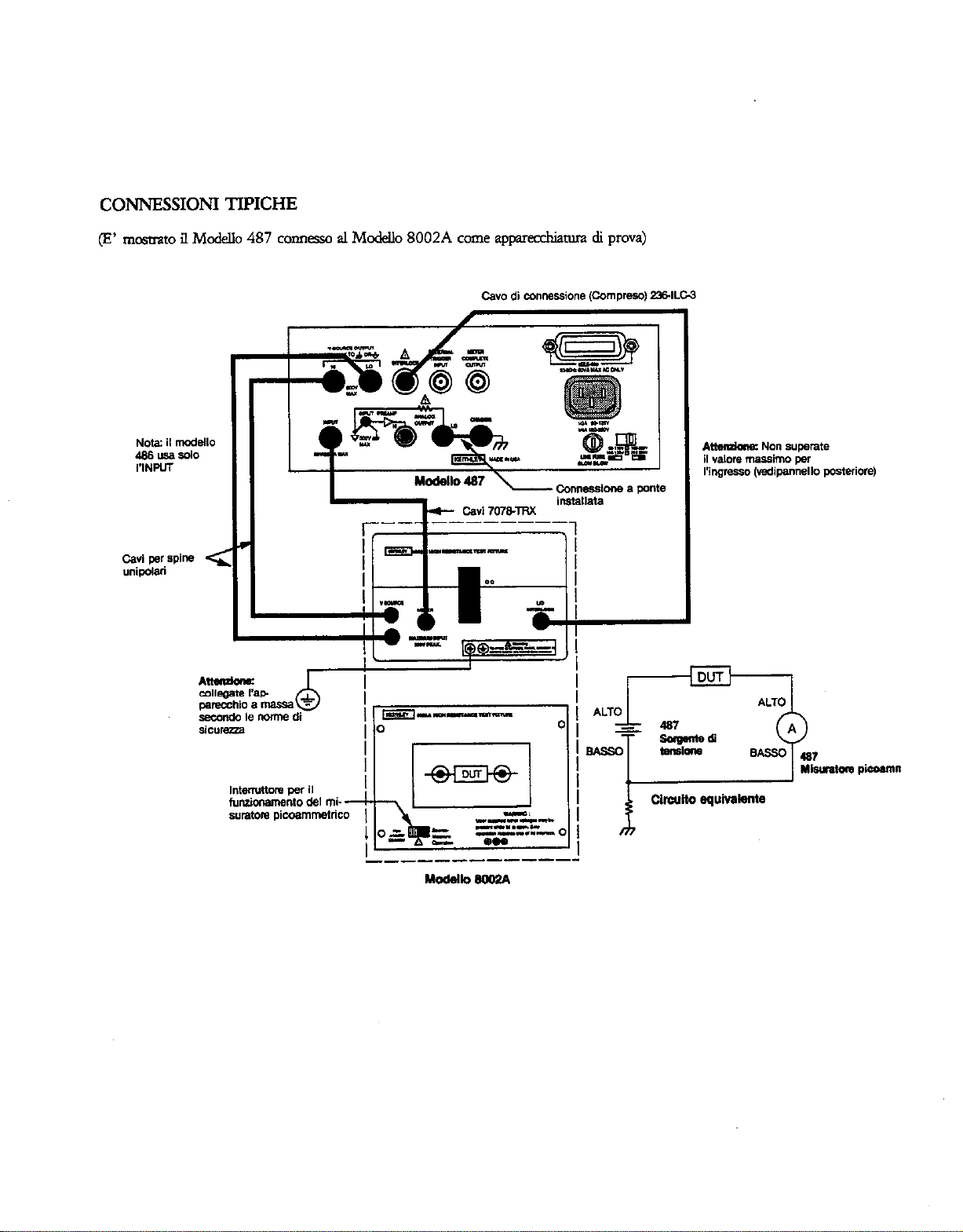
c0NNEss10NI TIPICHE
(E’ n-,nstrato il Mod& 487 connesso al Mod& 8002A come aw&tura di prova)
i
.__---_-----
Mdek.8W2A
11-w-w
-I”....L
Page 17
Page 18
___ _-------
M-m-
.o
.-
1
-"=-I
zz"
Z3ZZ!kZ
i3iL
_----B-e-----
E=JL 8oOP.A
Page 19
ADVERTENCIAS DE SEGURIDAD
SUMARIO DE CONTROL
Las precaucione siguientes deben ser observadas arms de war
los Modelm 4861487. Remitirse al manual principal para informa&n detdada de xgtuidad e instmccion~ completas de fundonamiento.
Tener cuidado extreme cuando hay la posibilidad de chque elktrim. F’wdem existi voltajes letaks en ks davijas de tida del
Mod& 487 6 en el accesorio de prueba. El Ins&to National
Ameicmo de Norms (ANSI) expose que e&e un peligro de
chcque cuando bay presents niveks de vohaje de mk de 30V
VCM (valor cuadrhtico media) 0 de 42,4V pica. Una buaa
pktica de seguridad es la de espemr que haya voltajes
peligmscs presentcs en cdquier circuito desconocido
antes de medirlo.
LNTENSIDAD DE PRESENTACION (DLWAY INllW
SIm): selffdonar
LOCAL (LOCAL):
OperadLin de la llave de] panel delantero.
MENU (MEh’U): Se usa con lar Uaves del cursor o perilla para
mdigum lo siguiente: alma- ‘elm de dates, recuperaci6Il
de dam, limite de coniam 0 (Mcdelo 487), integradn, bam
IEEE-488 (balm 0 tile voz), surdtuci6n, autqlmeh, ebminacibn de fallas, cezdilmtibn y calibraci6n de fuente de voltaje (V)
(sdo
Mod&
preentack% normal/amotigzuh/apa~da.
Pane a la unidad en acci6n local y restaura la
487).
CAMBIO SALWA (SHFi-m: S&b del MENU o activa-
citi de Prepara&n (SETUP).
COMPROBACION DE CERO (ZERO CHECK):
compmbacih de desplammientos y dek ser inhabilitado par-a ob
tenermamedici6nde~deenuada.
Permite la
CORFECION DE DEV’LAZAMZW TO (SHIFT COR-
RECT R& correcd6n autcm&ica de cero para balancear de
plazaodentos del instnunento.
Fm-Ro (EllTER): Habilita 0 inbabilita el 0 los iiltm s.2k.io
rlados.
No war nin@n objeto que pudka provea un camino a la cctieme al Iado comirn &I circuim bajo prueba o la tiena de la
line3 de energia.
~GAMAA~GE):UsalasUaverdegamapara~~onar
lmgamade conimte mis elm 0 mAs baja.
CAMBIO GAMA AUTOMATICA (SHIFT AUTO
RANGE)): Se wa pm bab la gama autodtica.
PREPARACION (SE77lP): Usado cm Uaves de tumor o periua
pal-a Nmiigurar la disposiciones sigulenm d-2 activti6n: moda-
lidad de activtibn, imervalo de activaci6n, demaa de activaci6n.
fuente de acdvacih.
OPERACION (OPERAlF): Siti k
en Funcionamiu~ta o Espwa.
Fueme V del Modelo 487
AC’i7XACION (TRIGGER): Se deprime para activar una kcturd 0 catlauar al almacenamulto de dam.
PREAJUSZE(P~: OS& emre cim v&n-es de la
preajustados (s5lo Mod& 487).
CAMBIOS OHMIOS v/c (SHIJT OHMS v7q se
sek@ilmal otios Voltaje coniente.
Fueme V
optime para
Page 20
CONEXIONES TIPICAS
(Mod.90 487 mcsuado conmado a arreylrio de pm& M&lo 8002A)
- .--------.
w-P--
Circuit0 equivatente
i
Page 21
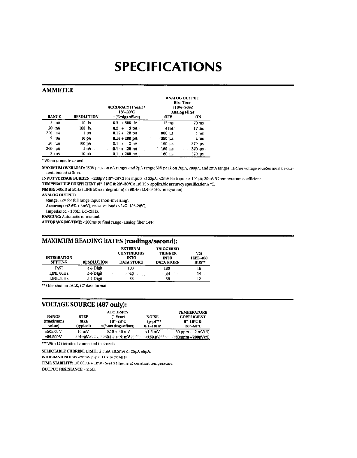
SPECIFICATIONS
MAXIMUM READING RATES (readings/second):
VOLTAGE SOURCE (487 only):
Page 22
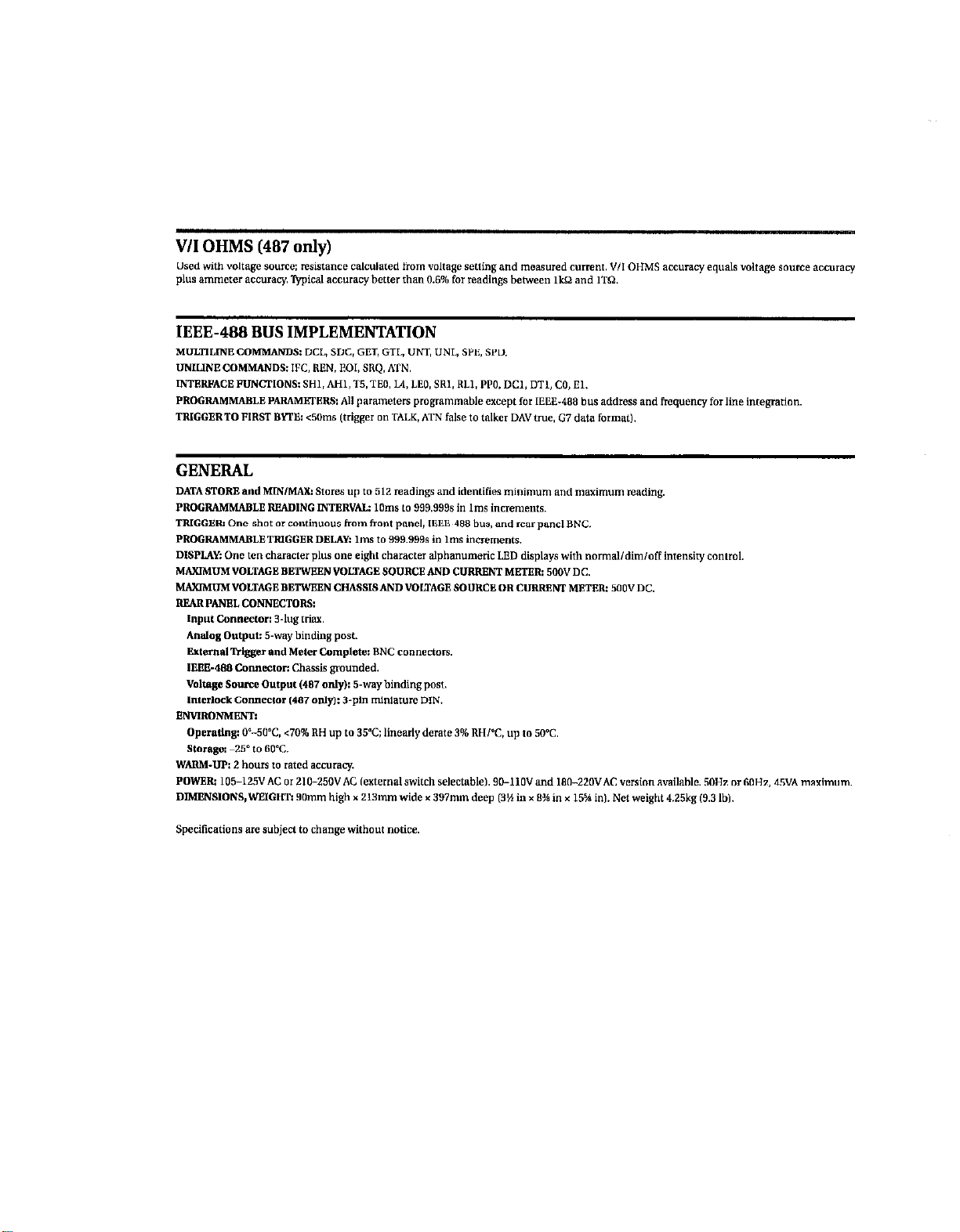
IEEE-488 BUS IMPLEMENTATION
Page 23
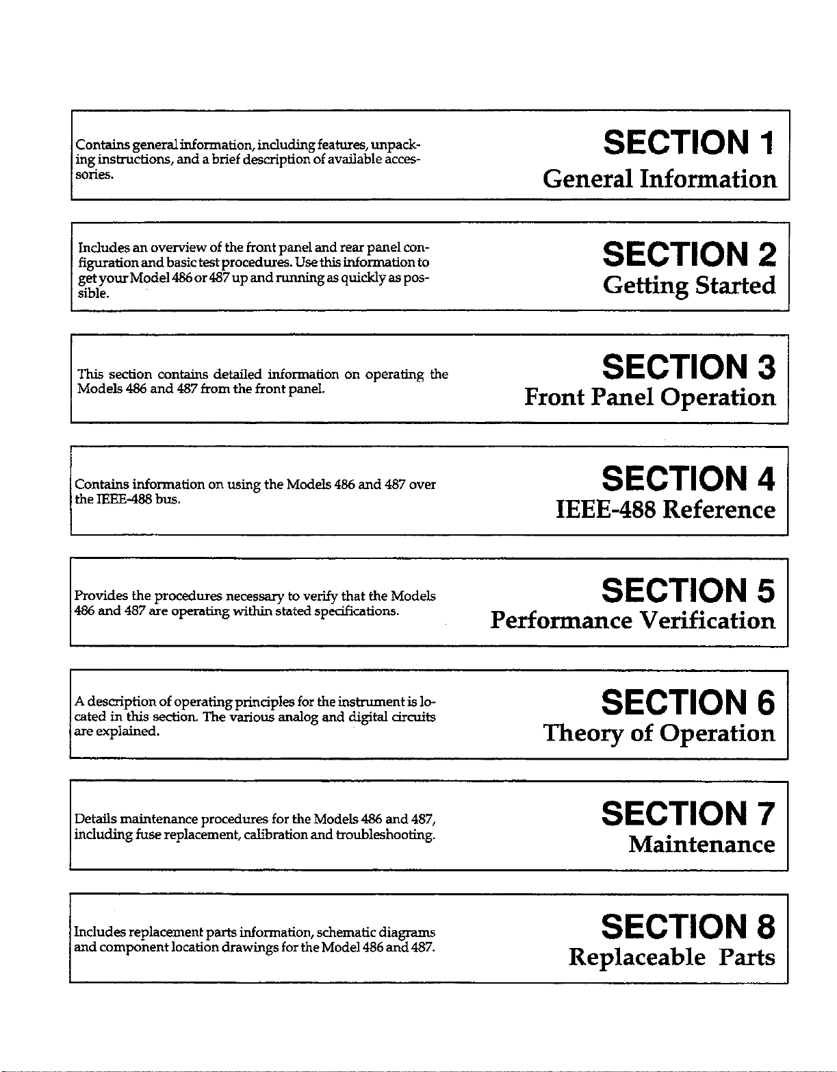
contains general information, inclding features, unpack-
ing insimxtions, and a brief description of available acces-
SO&S.
SECTION
General Information
1
Includes an overview of the front panel and rear panel configuration and basic test procedures. Use this information to
getyourMode1486or487up andmmingas quicklyaspossible.
This section contains detailed information on operating the
Models 486 and 487 from the front panel.
SECTION 2
Getting Started
SECTION 3
Front Panel Operation
Contains information on using the Models 466 and 487 over
the IEEE-488 bus.
SECTION 4
IEEE-488 Reference
Provides the procedures necessary to verify that the Models
486 and 487 are operating within stated specifications.
SECTION 5
Performance Verification
I 1
I
A description of operating principles for the instrument is located in this section. The various analog and digital circuits
are explained.
Details maintenance procedures for the Models 486 and 487,
including fuse replacement, calibration and troubleshooting.
Includes replacement parts information, schematic diagrams
and component location drawings for the Model 486 and 487.
I
SECTION 6
Theory of Operation
SECTION 7
Maintenance
SECTION 8
Replaceable Parts
Page 24

Page 25
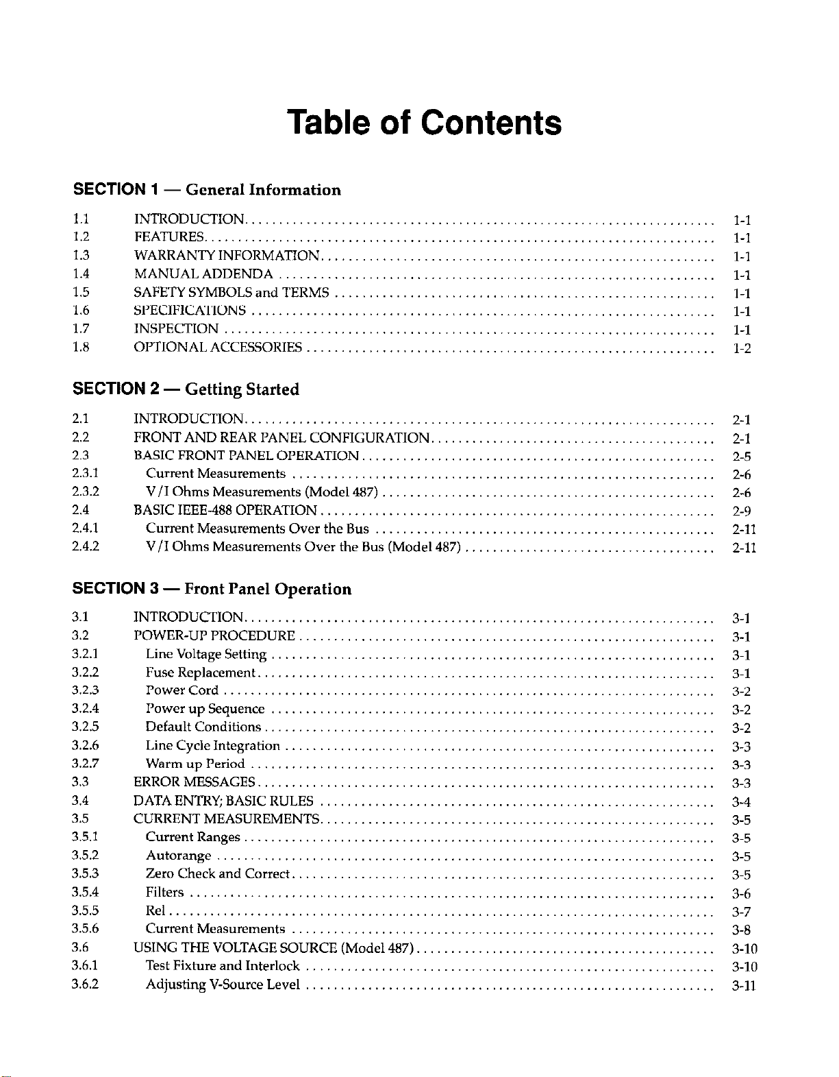
Table of Contents
SECTION 1
1.1
1.2 FEATURES.
1.3 WARRANTY INFORMATION,
1.4
1.5
1.6
1.7
1.8
SECTION 2
2.1
2.2
2.3
2.3.1
2.3.2
2.4
2.4.1
2.4.2
SECTION
- General Information
INTRODUCTION.
MANUAL ADDENDA
SAFETY SYMBOLS and TERMS
SPECIFICATIONS
INSPECTION
OPTIONAL ACCESSORIES
- Getting Started
INTRODUCTION
FRONT AND REAR PANEL CONFIGURATION,
BASIC FRONT PANEL OPERATION.
Current Measurements
V/I Ohms Measurements (Model 487)
BASIC IEEE-488 OPERATION. .......................
Current Measurements Over the Bus
V/I Ohms Measurements Over the Bus (Model 487)
...................................
............................
3 - Front Panel Operation
.................
...............
................
.......
...
.................
.................
.................
.................
.................
.................
.................
.................
.........
.........
.........
.........
.........
.........
.........
.........
..............
..............
..............
..............
..............
..............
..............
..............
2-l
2-l
2-5
2-6
2-6
2-9
2-11
2-11
3.1
3.2
3.2.1
3.2.2
3.2.3
3.2.4
3.2.5
3.2.6
3.2.7
3.3
3.4
3.5
3.5.1
3.5.2
3.5.3
3.5.4
3.5.5
3.5.6
3.6
3.6.1
3.6.2
INTRODUCTION.
POWER-UP PROCEDURE
Line Voltage Setting
Fuse Replacement
Power Cord
Power up Sequence
Default Conditions
Line Cycle Integration
Warm up Period
ERROR MESSAGES
DATA ENTRY; BASIC RULES
CURRENT MEASUREMENTS.
Current Ranges.
Autorange
Zero Check and Correct.
Filters
Rel......................................
Current Measurements
USING THE VOLTAGE SOURCE (Model 487)
Test Fixture and Interlock
Adjusting V-Source Level
3-l
3-1
3-l
3-l
3-2
3-2
3-2
3-3
3-3
3-3
3-4
3-5
3-5
3-5
3-5
3-6
3-7
3-8
3-10
3-10
3-11
Page 26
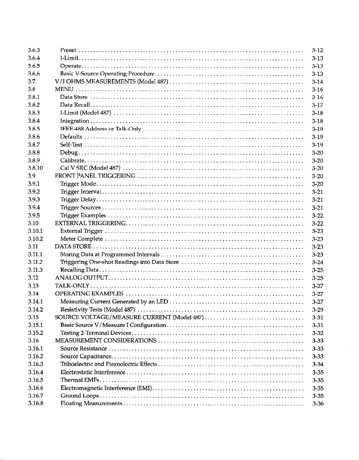
3.6.3
3.6.4
3.6.5
3.6.6
3.7
3.8
3.8.1
3.82
3.8.3
3.8.4
3.8.5
3.8.6
3.8.7
3.8.8
3.8.9
3.8.10
3.9
3.9.1
3.9.2
3.9.3
3.9.4
3.9.5
3.10
3.10.1
3.102
3.11
3.11.1
3.112
3.11.3
3.12
3.13
3.14
3.14.1
3.14.2
3.15
3.15.1
3.15.2
3.16
3.16.1
3.16.2
3.16.3
3.16.4
3.16.5
3.16.6
3.16.7
3.16.8
Preset .............................................................................
I-Limit .............................................................................
Operate ............................................................................
Basic V-Source Operating Procedure.
V/I OHMS MEASUREMENTS (Model 487)
..................................................
..............................................
MENU ..............................................................................
DataStore .........................................................................
DataRecall .........................................................................
I-Limit(Model487) .................................................................
Integration .........................................................................
IEEE-488AddressorTalk.Only .......................................................
Defau~s ...........................................................................
Self-Test ...........................................................................
Debug .............................................................................
Calibrate ...........................................................................
CalVSRC(Mode1487) ..............................................................
FRONTPANELTRIGGERING .........................................................
TriggerMode .......................................................................
TriggerInterval...............................................................~
TriggerDelay .......................................................................
Trigger Sources
.....................................................................
Trigger Examples ...................................................................
EXTERNAL TRIGGERING.
............................................................
ExternalTrigger ....................................................................
Meter Complete ....................................................................
DATASTORE ........................................................................
Storing Data at Programmed Intervals, ................................................
Triggering One-shot Readings into Data Store
..........................................
RecallingData ......................................................................
ANALOGOUTPUT ...................................................................
TALK-ONLY .........................................................................
OPERATINGEXAMPLES .............................................................
Measuring Current Generated by an LED ..............................................
Resistivity Tests (Model 487) .........................................................
SOURCE VOLTAGE/MEASURE CURRENT (Model 487). .................................
Basic Source V/Measure I Configuration.
..............................................
Testing2-TerminalDevices ...........................................................
MEASUREMENT CONSIDERATIONS ..................................................
Source Resistance. ..................................................................
SourceCapacitance ..................................................................
Triboelectric and I’iezoelectric Effects. .................................................
Electrostatic Interference. ............................................................
ThermalEMFs ......................................................................
Electromagnetic Interference (EMI). ...................................................
GroundLoops ......................................................................
Floating Measurements
..............................................................
.....
3-12
3-13
3-13
3-13
3-14
3-16
3-16
3-17
3-18
3-18
3-19
3-19
3-19
3-20
3-20
3-20
3-20
3-20
3-21
3-21
3-21
3-22
3-22
3-23
3-23
3-23
3-23
3-24
3-25
3-25
3-27
3-27
3-27
3-29
3-31
3-31
3-32
3-33
3-33
3-33
3-34
3-35
3-35
3-35
3-35
3-36
Page 27
SECTION 4
- IEEE-488 Reference
4.1
4.2
4.2.1
4.2.2
4.2.3
4.2.4
4.2.5
4.2.6
4.2.7
4.2.8
4.2.9
4.2.10
4.2.11
4.2.12
4.2.13
4.2.14
4.2.15
4.2.16
4.2.17
4.2.18
4.2.19
4.2.20
4.2.21
4.2.22
4.2.23
4.2.24
4.3
4.3.1
4.3.2
4.3.3
4.3.4
4.3.5
4.3.6
4.3.7
4.3.8
4.4
4.5
4.6
4.7
4.7.1
4.7.2
4.7.3
4.8
INTRODUCTION
DEVICE-DEPENDENT COMMAND PROGRAMMING
A-Display Intensity
B-ReadingSource
C . Zero Check and Zero Correct. ....................................................
D-Display.
F-V/IOhms
G-DataFormat
H-HitControl
J-Self-Tests. ......................................................................
K . EOI and Bus Hold-Off. ..........................................................
L-Default Condlhons or Calibration. ................................................
M - SRQ Mask and Serial Poll Byte Format
N-DDataStore;ArmandSetSize..
0-Operate(Mode1487)
P-Filters
Q-Interval
R-Range .........................................................................
S~IntegrationPeriod
T-Trigger
u-status .........................................................................
V-VoltageSource
W~Delay .........................................................................
X-Execute
Y-Terminator
Z-Relative
GENERAL BUS COMMANDS. .........................................................
REN(RemoteEnable)
IFC (InterfaceClear) .................................................................
LLO(LocalLockout)
GTL (Go To Local) and Local .........................................................
DCL(DeviceClear)
SDC(SelectiveDeviceClear)
GET (Group Execute Trigger)
SPE, SPD (Serial Polling)
IEEE-488BUSCONNECTIONS
PRIMARY ADDRESS SELECTION
CONTROLLER PROGRAMMING
FRONT PANEL ASPECTS OF IEEE-488 OPERATION .....................................
Front PanelError Messages
IEEE-488 Status Indicators. ...........................................................
LOCALKey
BUS DATA TRANSMISSION TIMES ....................................................
.....................................................................
...................................
...............................................................
.................................................................
......................................................................
......................................................................
...................................................................
....................................................................
..
............................................
...................................................
............................................................
.........................................................................
.......................................................................
...............................................................
........................................................................
.................................................................
........................................................................
.....................................................................
.......................................................................
................................................................
.................................................................
..................................................................
.........................................................
.........................................................
.............................................................
.........................................................
......................................................
......................................................
...........................................................
........................................................................
4-l
4-1
4-6
4-7
4-8
4-9
4.10
4-11
4-15
4-16
4-17
4.19
4-21
4-24
4.26
4-27
4-28
4-29
4-30
4.31
4-32
4-38
4-39
4-40
4-41
4-42
4-44
4-44
4-44
4-45
4-45
4-45
4-45
4-45
4-46
4-46
4-47
4-48
4-48
4-48
4-50
4-51
4-51
Page 28
SECTION
5 - Performance Verification
5.1 INTRODUCTION
5.2 ENVIRONMENTALCONDITIONS
5.3 INITIALCONDITIONS
5.4 REQUIREDTESTEQUIPMENT
5.5 VERIFICATION PROCEDURES ........................................................
5.5.1 PicoammeterVeri~cation..
5.5.2 Voltage Source Verification (Model 487). ...............................................
SECTION 6
6.1
6.2 ANALOG CIRCUITS.
6.2.1 Input Amplifier.
6.2.2 Analog Filter
6.2.3 Multiplexer . ..__. .., ., ,., ._, ,_
6.2.4 +2.8V Reference
6.2.5 Analog Output
6.2.6 Voltage Source (Model 487).
6.3 ANALOG CONTROL CIRCUITRY.
6.4
6.5 DIGITAL CIRCUITS
6.5.1
6.5.2
6.5.3 Display/Keyboard.
6.5.4 IEEE-488 Interface .
6.6 POWER SUPPLIES
6.6.1 ACLineInput..........................
6.6.2
6.6.3
6.6.4
- Theory of Operation
INTRODUCTION
A/D CONVERTER
Digital Block Diagram.
Microcomputer
*15V Supplies
+5VA Supply. .
+6.5V Supply.
....................................................................
.....................................................
...............................................................
........................................................
..........................................................
.
.
.
. .
5-l
5-l
5-1
5-l
5-2
5-2
s-4
6-l
6-1
6-1
6-2
6-3
6-3
6-5
6-5
6-6
6-8
6-9
6-9
6-11
6-12
6-13
6-14
6-14
6-14
6-14
6-14
SECTION
7.1 INTRODUCTION . . . . . . . . . . . . . . . . . . . . . . . . . .._.
7.2 LINE FUSE REPLACEMENT.
7.3
7.3.1
7.3.2
7.3.3
7.3.4 Warm-Up Period.
7.3.5 Front Panel Calibration
7.3.6 IEEE-488 Bus Calibration . .
7.4 HANDLING AND CLEANING PRECAUTIONS
7.5 DISASSEMBLY................................
7.5.1 CoverRemoval..............................
7.5.2 Shield Removal.
7 - Maintenance
CALIBRATION.
Recommended Calibration Equipment.
Environmental Conditions
CAL LOCK Switch.
7-1
7-l
7-1
7-1
7-2
7-2
7-2
7-2
7-6
7-8
7-9
7-9
7-11
Page 29
7.5.3
7.5.4
7.6
7.7
7.7.1
7.7.2
7.7.3
7.7.4
7.7.5
7.7.6
7.7.7
Front Panel Removal
Circuit Board Removal.
................................
..............................
SPECIAL HANDLING OF STATIC SENSITIVE DEVICES
TROUBLESHOOTING
Recommended Troubleshooting Equipment
Self-Test
...........................................
Analog Control Lines.
A/D Test Mode
Troubleshooting Procedures
Input Offset Voltage Adjust.
Fusible Resistor Replacement,
................................
............
...............................
.....................................
..........................
..........................
........................
..........
..........
..........
..........
..........
..........
..........
..........
..........
..........
..........
7-11
7-11
7-11
7-12
7-12
7-12
7-12
7-13
7-13
7-19
7-19
SECTION
8.1
8.2
8.3
5.4
8.5
8 - Replaceable Parts
INTRODUCTION........................................................
PARTSLISTS............................................................
ORDERINGINFORMATION..............................................
FACTORYSERVICE......................................................
SCHEMATIC DIAGRAMS AND COMPONENT LOCATION DRAWINGS.
APPENDICES
A
B
C ASCII Character Codes and IEEE-488 Multiline Interface Command Messages.
D
E
Device-dependent Command Summary
Interface Function Codes.
Controllerrrograms.......................................................
IEEE-488BusOverview....................................................
8-l
8-l
8-l
8-l
8-l
A-l
B-l
C-l
D-l
E-l
Page 30

Page 31

List of Illustrations
SECTION 2 - Getting
Figure 2-l
Figure 2-2
Figure 2-3
Figure 2-4
Figure 2-5
Figure 2-6
SECTION 3
Figure 3-l
Figure 3-2
Figure 3-3
Figure 3-4
Figure 3-5
Figure 3-6
Figure 3-7
Figure 3-8
Figure 3-9
Figure 3-10
Figure 3-11
Figure 3-12
Figure 3-13 Meter Complete Specifications.
Figure 3-14
Figure 3-15
Figure 3-16
Figure 3-17
Figure 3-18
Figure 3-19
Figure 3-20
Figure 3-21
Figure 3-22
Figure 3-23
Figure 3-24
Model 486 Front Panel.
Model 487 Front Panel.
Model 486 Rear Panel.
Model 487 Rear Panel.
Connections to Measure Current.
Connections for V/I Ohms Measurements
- Front Panel Operation
Line Voltage Switch and Line Fuse
Data Entry.. .....................................................................
Trim Input Connector (3-Lug)
Picoammeter Connections.
Model 487 V-Source Output Terminals,
InterlockConnections.. ...........................................................
InterlockConnections .............................................................
V-SourceAdjust ..................................................................
Basic V-Source Connections
V/I Ohms Connections (Source V Measure I)
TriggerConnectors ................................................................
External Trigger Pulse Specifications.
Typical Analog Output Connections.
Setup for MeasureLED Current
Connections for Resistivity Test,
Configuration for Surface Resistivity
Configuration for Volume Resistivity
Simplified Model from Source Resistance and Source Capacitance Effects
TriboelectricEffect ................................................................
PiezoelectricEffect ................................................................
Multiple Ground Points Create a Ground Loop
Eliminating Ground Loop.
Improper Method to make Floating Measurements.
Started
.........................................................
........................................................
.........................................................
..................................................
......................................................
..............................................
.........................................
................................................
.....................................................
................................................
.....................................................
....................................................
................................................
................................................
.......................................
...................................
................
2-2
2-3
2-4
2-5
2-7
2-8
3-l
3-4
3-8
3-9
3-10
3-11
3-11
3-12
3-14
3-15
3-23
3-23
3-23
3-26
3-29
3-30
3-30
3-31
3-33
3-34
3-34
3-35
3-36
3-36
SECTION
Figure 4-1
Figure 4-2
Figure 4-3
Figure 4-4
Figure 4-5
Figure 4-6
Figure 4-7
4 - IEEE-488 Reference
ASCII Data Format (G2; Prefix and Suffix).
G6 and G7 Binary Data Formats (Counts/Exponent).
G4 and G5 Binary Data Formats (IEEE Std. 754).
Headers For Binary Formats.
SRQ Mask and Serial Poll Byte Format.
UO Machine Status Word (Factory Defaults Shown).
Ul Error Status Word.
4-11
4-12
4-12
4-13
4-21
4-33
4.34
Page 32

Figure 4-8
Figure 4-9
Figure 4-10
Figure 4-11
U9 Voltage Source Error Status Word
IEEE-488 Connector.
IEEE Connections.
.......................
IEEE-488 Connector Location.
Figure 4-12 Contact Assignments.
.....................
.............
....................
.......
.......
.......
.......
.......
.......
..........
..........
..........
..........
..........
. . . .
. . .
4-36
4-46
447
4-47
4-47
SECTION
5 -Performance Verification
Figure 5-l Setup for Picoammeter Verification. . .
Figure 5-2 Setup for Voltage Source Verification (Model 487)
SECTION 6
Figure 6-1
Figure 6-2
Figure 6-3
Figure 6-4
Figure 6-5
Figure 6-6
Figure 6-7
Figure 6-8
Figure 6-9
Figure 6-10
Figure 6-11
Figure 6-12
Figure 6-13
Figure 6-14
Figure 6-15
Figure 6-16
Figure 6-17
- Theory of Operation
Overall Block Diagram
Simplified Model of Input Amplifier
Zero Check Configuration
Offset Voltage Adjust Circuit
Analog Filter Circuitry
Multiplexer .............................
Multiplexer Phases.
Analog Output Circuit (Simplified) .
Simplified Model of V-Source (Model 487)
Analog Control Circuitry
Control Word
...........................
A/D Converter Simplified Schematic.
Digital Block Diagram.
Memory Map
...........................
Simplified Block Diagram of Serial Port.
Display Block Diagram.
Power Supply Block Diagram
...................
.......
................
..............
...................
......................
.................
...................
....
..................
.............
.......
.......
.......
.......
.......
.......
.......
.......
.......
.......
.......
.......
.......
.......
.......
.......
.......
.......
.......
.......
.......
.......
.......
.......
.......
.......
.......
.......
.......
.......
.......
.......
.......
.......
5-3
5-5
6-l
6-2
6-2
6-2
6-3
6-4
. 6-5
. . . ..I. . 6-5
6-5
6-7
6-8
6-9
6-10
6-11
. .
6-12
6-13
6-14
SECTION 7
Figure 7-l
- Maintenance
Cal Lock Switch
Figure 7-2 Setup for Picoammeter Calibration.
Figure 7-3
Setup for Voltage Source Calibration (Model 487)
Figure 7-4 ExplodedView..................................
Figure 7-5 Test Point, R198 and R203 Locations,
Figure 7-6 Integrator Output (Typical)
APPENDICES
Figure E-l
Figure E-2
Figure E-3
IEEE-488 Bus Configuration.
IEEE-488 Handshake Sequence
Command Codes
........................
..............
............
.......
.......
.......
. . .
. . .
7-2
7-4
7-5
7-10
7-14
7-17
E-2
E-3
E-6
.......
.......
.......
.......
.......
.......
.......
.
.......
.......
..........
..........
..........
..........
..........
..........
Page 33

List of Tables
SECTION
Table 2-l
2 - Getting Started
SECTION 3
Table 3-l
Table 3-2
Table 3-3
Table 3-4
Table 3-5
Table 3-6
Table 3-7
Table 3-8
Table 3-9
Table 3-10
Table 3-11
SECTION 4
Table 4-l
Table 4-2
Table 43
Table 4-4
Table 4-5
Table 46
Table 4-7
Abbreviated Command Summary.
- Front Panel Operation
Line
Voltage
LineFuseSelection
Factory Default Conditions (Front Panel).
Error Messages..
CurrentRanges
Analog Filter Effects.
Model 487 V-Source
MENU Items
Typical Analog Output Values
Minimum Recommended
Feedback Capacitor (CF) Values.
Selection (50.60~2)
................................................
.................................................
...................................................
....................................
- IEEE-488 Reference
Device-dependent Command Summary
Typical Bus Holdoff Times
Factory Default Conditions.
IEEE Contact Designations.
HP BASIC 4.0 IEEE-488 Statements.
IEEE-488 Error Messages.
Typical Trigger to First Byte Out Times.
............................
.....................
.....................
.....................
.....................
.....................
.....................
.............
.............
.............
.............
.............
.............
.............
,,....
.,....
,.....
,_....
,....,
2-10
3-l
3-2
3-3
3-4
3-5
3-6
3-10
3.17
3.26
3-33
3-33
4-2
4-18
4.19
444
4-48
4-49
4-51
SECTION
Table 5-1
Table 5-2
SECTION 6
Table 6-l
Table 6-2
SECTION
Table 7-l
Table 7-2
Table 7-3
Table 7-4 Recommended Troubleshooting Equipment
5 - Performance Verification
VerificationEquipment............................................................
Picoammeter Verification
- Theory of Operation
RangeRelays
Filter Relay Switching
.....................................................................
.............................................................
7 - Maintenance
LineFuseSelection
CalibrationEquipment
Picoammeter Calibration.
................................................................
............................................................
..........................................................
..........................................
5-l
5-3
6-2
6-4
7-l
7-2
7-3
7.12
Page 34

Table 7-5
PowerSupplyChecks
Table 7-6 Digital Circuitry Checks
................................................
..............................................
Table 7-7 Analog Circuitry Checks. .............................................
Table 7-8
V-Source Checks (Model 487 Only).
....................................
APPENDICES
...........
...........
...........
...........
7-14
7-15
7-16
7-18
Table A-l
Table B-l
Table D-l
Table E-l
Table E-2
Table E-3
Table E-4
Table E-5
Device-dependent Command Summary
Model 486/487 Interface Function Codes
........................
.......................
BASIC Statements Necessary to Send Bus Commands
IEEE-488 Bus Command Summary.
Hexadecimal and Decimal Command Codes
Typical Addressed Command Sequence
Typical Device-dependent Command Sequence.
IEEE Command Groups
......................................
............................
....................
........................
.................
............
...........
...........
...........
...........
...........
.
...........
...........
...........
A-l
B-l
D-3
E-4
E-7
E-7
E-7
E-8
Page 35

SECTION 1
General Information
1.1 INTRODUCTION
This section contains general information about the
Model 486 Picoammeter and the Model 487 Picoammeter/vo1tage S&we.
1.2 FEATURES
Some important Model 486/487 features include:
DualDisplays-Alocharacteralphanumericdisplay
used for current readings and front panel messages,
and a smaller 8 character alphanumeric display for
front panel messages and the voltage source setting of
the Model 487.
zero correct - used to cancel internal offsets.
Relative @EL) -Used to establish baselines.
DataStore-CCanstoreupto512readingsandisaccessible over the bus 01 from the front panel.
User Programmed Default Conditions - Establish
present operating setup conditions as power-up de
fault conditions.
Talk-Only - From the front panel, set instnmwnt to
send readings over the bus to a listen-only device,
such as a printer.
V/I ohms resistance measurements up to 5OPQ
(Model 487 only).
Preset (Model 487) toggles between preset V-source
values
1.4 MANUAL ADDENDA
Any improvements or changes concerning the instrument or manual will be explained in an addendum included with the manual. Be sure to note these changes
and incorporate them into the manual.
1.5
The following symbols and terms may be found on an instrument or used in this manual.
The A
should refer to the operating inskwiions located in the
instmction manual.
The WARNING heading used in this manual explains
dangers that might result in personal injmy or death. Always read the assodated information very carefully before performing the indicated procedure.
The CAUTION heading used in this manual explains
hazards that could damage theinstnunent. Such damage
may invalidate the warranty.
SAFETY SYMBOLS and TERMS
symbol on an insinunent indicates that the user
1.6 SPECIFICATIONS
Model 486/487 specifications may be found at the front
of this manual.
1.3 WARRANTY INFORMATION
Warranty information is located on the inside front cover
of this inskwtion manual. Should your Model 486/487
require warranty service, contact the Keithley represen-
tative or authorized repair facility in your area for further
information. when returning the instrument for repair,
be sure to fill out and include the service form at the back
of this manual in order to provide the repair facility with
the necessary information
1.7 INSPECTION
The Model 486/487 was carefully inspected, both electrically and mechanically before shipment. After unpacking all items from the shipping carton, check for any obvious signs of physical damage that may have occurred
during transit. Report any damage to the shipping agent
immediately. Save the original packing carton for possible future reshipment. The following items are included
with every Model 4%/487 order.
l-l
Page 36

SECTION 1
General Information
Model 486 Picoammeter or Model 487 Picoammeter/
Voltage Source.
Model 486/487 Instruction Manual.
Model 2.36~IX-3 Interlock Cable (Model 487 only)
Model 237-ALG-2 Triax to Alligator-clip Cable.
Quick Reference Guide
Additional Accessories as ordered.
If an additional instnxtion
manual
is required, order the
manual package, Keithley part number 486-901-00. The
manual package includes an instruction manual and any
pertinent addenda.
1.6 OPTIONAL ACCESSORIES
The following accessories are available
use with the Model 486/487.
Model 4.288-l SingleFixed RackMount Kif -Mounts a sin-
gle Model 486/487 in a standard 19 inch rack.
from
Keithley for
Model 61713~slot to.Z-lug Triax Adapter- Adapts INPUT
connector for 2slot triax cables.
Model 7007 Shielded IEEE-488 Cables - Connects the
Mode1486/487 to the IEEE-488 bus using shielded cables
to
reduce electromagnetic interference @Ml). The Model
7007-l is one meter in length and has an EMI shielded
IEEE-488 connector at each end. The Model 7007-2 is
identical to the Model 7007-1, but is two meters in length.
Model 7078-TRXTriaxiaJ Cables-Low noise cables terminated with 3&t male triaxial cormectors. The Model
7078~TRX-3 is
O.Qm
(3 ft.) in length, the Model
7078TRX-10 is 3m (10 ft.) in length, and the Model
7078-TRX-20 is 61x1(20 ft.) in length.
Model 8002A High Resistance Test Fixture -Use with the
Model 487 to make high resistance W/II measurements.
The Model 8002 is designed to minimize leakage currents
that could otherwise degrade the measurement. Connectors in&de one pair of 5-way binding posts, two 3-lug
biaxial connectors, and a standard interlock connector
for the safety interlock switch.
Model 4288-2 DwJ Fixed Rack Mount Kit - Mounts two
Model 486/487s in a standard 19 inch rack.
Model 61 OS Resistivity Chamber -Use with the Model487
to measure the volume and surface resistivity of test samples. Accommodates sheet samples 64 to 102mm (2.5 to 4
in.) in diameter and up to 6.4mm (0.25 in.) thick.
Model 8006 Component Test Fixture-Provides a convenient and practical way of making sensitive test measure-
ments
on a variety of standard packaged devices. Sockets
are provided for resistors, diodes, 4-, 8; IO-, and 12-lead
axial (TO) packages, and DIPS up to 28 pins. Connectors
include 16 3-lug triaxial, two BNC, five 5-way binding
posts, and a standard interlock connector for the safety
interlock switch.
1-z
Page 37

SECTION 2
Getting Started
2.1 INTRODUCTION
This section contains introductory information on using
the Model 486 Pico-eter and the Model 487 Picoammeter/Voltage Source. For detailed front panel and
IEEE-488 bus operation, refer to Sections 3 and 4 mpeclively.
2.2 FRONT AND REAR PANEL CONFIGURATION
Figure 2-1 and Figure 2-2 show the respective front panek of the Models 486 and 487, while Figure 2-3 and
Figure 2-4 show the respective rear panels. Each of these
figures includes important information that should be reviewed before operating the instrument.
2-l
Page 38

SECllON 2
Getting Started
l-lx-ml
Ygure 2-1. Model 486 Front Panel
2-2
Page 39

SECTION 2
Getting started
gure 2-2.
Model 487 Front Panel
2-3
Page 40

SECTION 2
Getting Started
I
3-lug Triax
Current input
Trigger Connections
An;og
Output Binding
Posts
Chassis
Ground
3inding Posts
IEEE-438 Connector
BNC
Calibration Switch
(sticker cows access hole)
In = Calibration enabled
Out = Calibration disabled
Note : Use shielded IEEE-488 cable
Line Fuse
CAUTION : Replac- .___
with one of same type ant
rating : WA, 90-125V
114
Line Power Input
WARNING : Connect to
grounded outlet using
3-wire power cord
& Line Voltage Switch
1 105W125V
21 O-250V
(Optional transformer
required for 90-l 1 OV,
1 SO-220V operation)
CAUTION : Operation
on improper line
voltage may damage
unit
A, 180.250V
‘igure 2-3.
Model 486
Rear
Panel
2-4
Page 41

Binding Post
Fipre 2-4.
Interlock
Cur& input r0s’s
Model 487 Rear Panel
IEEE-488 Connector
Note : Use shielded IEEE-488 cable
1 Out = Calibration disabled 1
Line Fuse
CAUTION : Replace fuse
with one of 8ame type and
rating : f/z?A. go-12Sv
l/4 A, 180-250v
SECTION 2
Getting Started
Line Power Input
WARNING : Connect to
grounded outlet using
%wirs power cord
- Line Voltage Switch
105v-125v
210-250”
,n^+;..“..l ‘-41rmer
~~l-.~--.-. -_ .lOV,
1 SO-22OV operation)
CAUTION : Ooeration
on Improper I&
Voltage may damage
““II
2.3 BASIC FRONT PANEL OPERATION
The following presents the basic information needed to
use the Model 486/487 to make current measurements.
For the Model 487, a procedure to use the voltage source
in conjunction with the picoammeter is provided to
demonstrate V/I Ohms resistance measurements.
NOTE
Make signal input low connections only to
II’UT LO. Do not use ANALOG OUTPUT
LO for input connections.
Before attempting to operate the instrument, verify that
the rear panel line voltage switch is in the correct position for the power line voltage in your area. Connect the
instrument to an appropriate power source using the
supplied line cord, then turn on the power by pressing
in the front panel POWER switch.
WARNING
Use only a grounded ac outlet to avoid a possible shock hazard.
CAUTION
Operating the instrument an an incorrect
line voltage may cause damage to the
instrument.
NOTE
If the front panel display should appear to be
inoperative,
try pressing the DISPLAY
INTENSITY key once or twice to restore the
display to normal intensity.
2-5
Page 42

SECTION 2
Getting Started
2.3.1
The steps below outline the basic procedure for using the
Mode1486/487 to make current measurements from the
front panel:
1.
2.
3.
4.
5.
6.
7.
8.
Current Measurements
Perform factory initialization as follows to return the
instnunent to factory default conditions:
Press and rele&e MFNIJ until the following
A.
message is displayed:
DEFAULTS
B.
Use the rotary knob, or the4 and b keys to display the following message:
DEFAULTS FACTORY
Press MENU. The instrument will return to the
C.
normal IneasuTement display state.
Note: Performing factory initialization is a convenient method to return the instrument to typi-
cally used operating states. Using factoiy defaults, zero check is enabled, autorange is enabled, and filter (digital + analog) is enabled.
Connect the rear panel triax INPUT connector to the
current source. For example, Figure 2-5 shows a
Keithley Model 263 source connected to the Model
486/4si
On the Model 486/487, press SHIFT and then COR-
RECT to perform zero cormztion. This will cancel
ally inted offsets.
On the Model 486/487, disable zero check by pressingZEROCHECK.The~OCHECKindicatorwill
turn off.
If you intend to suppress an offset current from the
external current source, perform the following steps:
A. Apply the current to be suppressed to the input.
That current will be measured and displayed on
the Model 4861487.
B. On the Model 486/487, press REL. The current
will be suppressed as indicated by the zeroed
display.
Apply the signal current to be measured to the input
of the Model 486/487.
Read the current measurement on the display of the
Model 486/487.
When the measurement is complete, enable zero
check to avoid accidental overloads to the instrument. In general, zero check should be left enabled
while the instrument is tuned on but not in use.
OK
2.3.2 V/I Ohms Measurements
(Model 487)
NOTE
The following procedure demonstrates how
to properly use the V-Source of the Model 487.
Keep in mind that the V-Source can be used as
an &dependent source for any appropriate
application.
For V/I Ohms resistance measurements, the Model 487
sources a voltage to a device under test (DUT) and measures the subsequent current. The resistance value of the
DLIT is automatically calculated (R = V/I) and displayed
in ohms.
The steps below outline the basic procedure for using the
Model 487 to make V/I Ohms measurements from the
front panel:
1. Performfactory initializationasfollows toretumthe
instroment to factors default conditions:
Press and relea;e MENU until the following
A.
message is displayed:
DEFAULTS OK
Use the rotary knob, or the 4 and b keys to dis-
B.
play the following message:
DEFAULTS
Press MENU. The instrument WiII return to the
C.
normal measurement display state.
Note: Performing factory initition is a con-
venient method to return the instrument to typically used operathg states. Using factory defaults, zero check is enabled, autorange is enabled, filter (digital + anslog) is enabled, I-limit is
set to 2.5mA.
2. SelecttheV/IOhmsfunctionbypressingSHIFTand
then OHMS (v/I).
3. With the DUT installed in an appropriate test fixture,
connect it to the V-Source and picosmmeter of the
Model 487. Figure 2-6 shows how to connect a DUT
that is installed in the Keithley Model 8002A t&t fixture to the Model 487.
WARNING
To prevent contact with possible hazardous
voltages, make sure the Model 487 interlock
FACTORY
2-6
Page 43

Equivalent Circuit
SECTION2
Geffina Sfarfed
2igure 2-5.
Connections to Measure Current
is properly connected to the test fixhm (see
Figure Z-6). With proper use of Interlock, the
V-Source will not apply voltage to the test
fixture when the lid of the test fix&m is
OPm
WAlZNlNG
To provide protection from shock hazards,
the test fixture chassis must be properly con-
nected to a safety earth ground. A grounding
wire (18 AWG or larger) must be attached se-
curely to the test fixture at a sczew temdnal
designed for safety grounding. The other
end of the ground wire must then be attached to a known safety earth ground.
Guard
Disabled
5. Set the V-Source of the Model 487 to the desired voltage level as follows:
A. Select the V-Source range. To select the 50V
range, keep pressing and releasing the, key until the 3JV mnge is displayed (i.e. OV on the 5OV
range is displayed as “OO.OWJ”). To select the
500V range, keep pressing and releasing the 4
key until the 5CW range is displayed (i.e. OV on
the SOOV range is displayed as “OOO.OOV”).
B. Use the 4 and b keys to position the cursor
Washing digit, on the digit to be modified.
C. Use the rotary knob to increase or decrease the
voltage level from the selected digit.
Note: As a general rule, the V-Source should be
set as high as possible to optimize V/I Ohms
measurement accuracy.
4. On the Model 487, press SHIFT and then CORRECT
to perform zero correction. This will cancel any internal offsets.
6. On the Model 487, press ZERO CHECK to disable
zero check, and press OPERATE to apply the pmgr-ed voltage to the test fixture. The resistance of
2-7
Page 44

SECTION2
Getting Started
the DLT will be measured and displayed on the
Model 487.
Note: Usingthe setup in Figure 2-6, resistance will be
displayed as a positive value. As long as both current
and voltage read positive (or both read negative),
then the V/I calculation wilI be displayed positive.
Negative V/I is displayed only if the V-Source or
.-- 70BTRX Cable
r;--1
----_---
pica-eter (but not both) have a negative read
out. V/I Ohms is simply the calculation of voltage
setting divided by meter reading.
7. When finished, place the V-Source in standby and
enable zero check.
31 I
~.__.._
il r----7 Ii LO
L-----------2
Model 8WZA
Connecfions for V/I Ohms Measurements
Ii .-
I
I
"ewroe
T
2-8
Page 45

SECTION 2
Getting Started
2.4 BASIC IEEE-488 OPERATION
The following information outlines the basic procedures
to use the Model 486/487 over the IEEE488 bus. An abbreviated summary of commands necessary for basic op-
eration is shown in Table 2-1. Simple controIler programs
thatcanbeused tosendthesecommand.sarelistedinAppendix D of this manual.
Before attempting to operate the inshument, perform the
following steps:
1.
With the power off, connect the Model 486/487 to
the IEEE-488 bus of the controller. A shielded
IEEE-488 cable such as the Keithley Model 7007 is
recommended.
2.
Verify that the rear panel line voltage switch is in the
correct position for the power line voltage in your
area. Connect the in.9troment to an appropriate
power source using the supplied line cord, then turn
on the power by pressing in the front panel POWER
switch.
WARNING
Use only a grounded ac outlet to avoid a pos-
sible shock hazard.
CAUTION
operating the instrument on an incorrect
line voltage may cause damage to the ins&u-
NOTE
If the tiont panel display should appear to be
inoperative, try pressing the DISPLAY II+
TFNSITY kev once or twice to restore the display to non&l intensity.
Verify that the programmed primary address dis-
3,
played on power-up is the same as the one you intend to specify in your program statements. For example, if the instnunent is currently set for an address of 22, the following message wiIl be briefly displayed on power-up.
IEEE-488
4.
If you desire to change the primary address of the in-
ADDR 22
strument, you can do so as follows:
A. Press and release MENU untiI the IEEE-488 ad-
dress is displayed.
B. Use the rotary knob (or the4 or, key) to display
the desired address (O-30).
C. With the desired address displayed, press
MENU to save it.
D. Press SHIFT and then EXIT to return to normal
operation.
2-9
Page 46

SECTION 2
Getting Started
Lnnmand Description
Table 2-l. Abbreviated Command Summary
30
3
2
TO
?l
xl
21
22
3,v
A
3
,6
30
31
?I
iit
B
RO
E
Ei
u5
Fz
U8
FO
Disable zero check
Enable zero check
Enable zero check and perform zero correction
Disable V/I ohms &lode1 487)
Enable V/I ohms (Model 487)
Return to factory default conditions and save (Ll)
Save present states as default conditions
Return to saved default conditions
Calibrate present messuwnent range using W’; v = -2E-3 to +2E-3 amps
Calibrate zero on present voltage source range (Model 487)
Caliirate full scale on present voltage souxe range (Model 487)
Prepare to calibrate present voltage source range (Model 487)
Place Model 487 V-Source in standby
Place Model 487 V-Source in operate
Disable digital and analog filters
Enable digital filter; disable analog filter
Disable digital filter; enable analog filter
Enable digital and analog filters
Enable autorange
Select 2nA range
Select 2OnA range
Select 2OOnA range
Select 2@ range
select 2o)lA mlge
Select 200@ range
select 2mA range
No range
No range
Disable autorange
Z-10
Vll,r,l
Specify voltage source (Model 487) level “n” in volts, range “I” and limit “1”;
n: -505.000 to +505.000
r: 0 = 50V range; I= 500V range
1:0=2?+4limit;1=2.5mAlimit
X Execukother device-dependent commands
Disable relative
E
z2,v
Enable relative using present reading as baseline
Enable relative using “v” as baseline;
Y = -2E-3 to +2E-3 amps for current
Y = OR to 5.OSEXQ for V/I ohms
z3
Enable relative using baseline previously defined.
Page 47
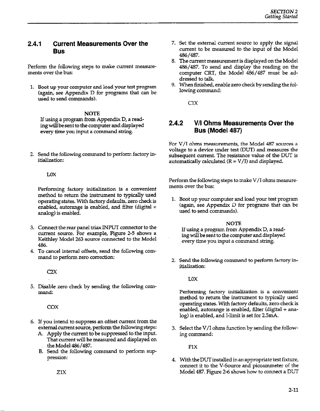
SECTION 2
Getting Started
2.4.1 Current Measurements Over the
Bus
Perform the following steps to make current measurements over the bus:
1.
Boot up your computer and load your test program
(again, see Appendix D for programs that can be
used to send commands).
NOTE NOTE
If using a program from Appendix D, a read- If using a program from Appendix D, a reading will be sent to the computer and displayed ing will be sent to the computer and displayed
every time you input a command string. every time you input a command string.
Send the following command to perform factory in-
2.
itialization:
LDX
Performing factory initialk&ion is a convenient
method to return the instrument to typicslly used
operating states. With factory defaults, zero check is
enabled, autorange is enabled, and filter (digital +
analog) is enabled.
Set the external current source to apply the signal
current to be measured to the input of the Model
486/487.
The current measurement is displayed on the Model
486/487. To send and display the reading on the
computer CRT, the Model 486/487 must be ad-
dressed to talk.
When finished, enable zero check by sending thefollowing command:
ax
2.4.2
V/I Ohms Measurements Over the
Bus (Model 487)
For V/I ohms measurements, the Model 487 sources a
voltage to a device under test (DLIT) and measures the
subsequent current. The resistance value of the DUT is
automatically calculated CR = V/I) and displayed.
Perform the following steps to make V/I ohms measurements over the bus:
1.
Boot up your computer and load your test program
(again, see Appendix D for programs that can be
used to send commands).
3.
Connect the rear panel triax INPUT comector to the
current source. For example, Figure 2-5 shows a
Keithley Model 263 source connected to the Model
486.
4.
To cancel internal offsets, send the following com-
mand to perform zero correction:
c2x
5.
Disable zero check by sending the following command:
cox
6.
If you intend to suppress an offset current
external current source, perform the following steps:
A. Apply the current to be suppressed to the input.
That current will be measured and displayed on
the Model 486/487.
B. Send the following command to perform sup-
pression:
ZlX
from
the
NOTE
If using a program from Appendix D, a reading will be sent to the computer and displayed
every time you input a command string.
2.
Send the following command to perform factory initialization:
LOX
Performing factory initialization is a convenient
method to return the instrument to typically used
operating states. With factory defaults, zero check is
enabled, autorange is enabled, filter kligital + analog) is enabled, and I-limit is set for 2.5mA.
Select the V/I ohms function by sending the follow-
3.
ing command:
FlX
With the DUT installed in an appropriate test fixture,
4.
connect it to the V-Source and picosmmeter of the
Model 487. Figure 2-6 shows how to connect a DIlT
2-11
Page 48

SEClYION 2
Getting Started
that is installed in the Keithley Model 8002A test fiwture to the Model 487.
WARNING
To prevent contact with possible hazardous
voltages, make sure the Model 487 interlock
is properly connected to the test fixture (see
Figure 2-6). With properuse of Interlock, the
V-Source will not apply voltage to the test
fixture when the lid of the test fixture is
open.
WARNING
To provide protection from shock hazards,
the test fixture chassis must be properly connected to a safety earth ground. A grounding
wire (18 AWG or larger) must be attached securely to the test fixture at a screw terminal
designed for safety grounding. The other
end of the ground wire must then be attached to a known safety earth ground.
5.
To cancel internal offsets, send the following
mand to perform zero correction:
com-
6.
Use the
V command to program the V-Source. For
example, to set the V-Source for lOV, send the following command string:
VIOX
Note: Asageneralrule,theV-Sourceshould beset as
high as possible to optimize measurement accuracy.
7.
Disable zero check by sending the following com-
man&.
cox
8.
To source voltage to the DUT, place the V-Source in
operate with the following command:
01x
9.
The resistance measuement is displayed on the
Model 487. To send and display the reading on the
computer CRT, the Model 487 must be addressed to
talk.
10.
When finished, enable zero check and place the V-
Source in standby by sending the following command string:
C2X
CIGQX
Z-12
Page 49

SECTION 3
Front Panel Operation
3.1 INTRODUCTION
This section contains the detailed information necessary
to use the insttument from the front panel. These operations (except for IEEE-488 address selection and frequency for line integration) can also be programmed
over the IEEE-488 bus, as described in Section 4.
3.2 POWER-UP PROCEDURE
3.2.1
The instrument is designed to operate from 10.512%’ or
210-25OV line power ranges. A special transformer may
be installed (at factory) for 90-IlOV and lSC-220V ranges.
The operating voltage that the instrument is configured
to operate at is indicated on the line voltage slide switch
located on the rear panel (see Figure 3-l). The required
switch positions for the available line voltages are summarized in Table 3-l. If the line voltage setting needs to
be changed, proceed as follows:
Table 3-l. Line Voltage Selection (5LMOHz)
Line Voltage Setting
Voltage Selection
Line Voltage
Switch Position
I
I105-125v I
115v
I
in the switch slot and slide it over to the alternate position.
Install a fuse consistent with the operating voltage,
2.
as described in the next paragraph.
Figure 3-1.
Line Voltage Switch and Line Fuse
3.2.2 Fuse Replacement
A rear panel fuse located adjacent to the line voltage
switch (see Figure 3-I) protects the power line input of
the instrument If the fuse needs to be replaced (line voltage switch sethg changed or suspected blown fuse),
perform the following steps:
WARNING
Make sure the instrument is disconnected
from the power line and other equipment
before replacing the fuse.
1.
With the power off, place the end of a flat-blade
screwdriver into the slot in the rear panel line LINE
FUSE holder. Push in gently and rotate the fuse carrier one-quarter turn counterclcckwise. Release
pressure on the holder and its internal spring will
push the fuse and carrier out of the holder.
2.
Remove the fuse and replace it with the type recommended in Table 3-2.
WARNING
Make sure the Model 486/487 is disconnected from the power line and all other
equipment before proceeding.
1. Locate the line voltageswitch on the rear panel (see
Figure 31). Place the blade of a screwdriver into slot
CAUTION
Donotuse afusewithahighercurrentrating
than specified, or instrument damage may
occur. If the instrument repeatedly blows
fuses, locate and correct the cause of the
trouble before replacing the fuse. See the
maintenance section for troubleshooting information.
3-1
Page 50

SECTION 3
Front Panel Operation
Table 3-2. Lie Fuse Selection
3. Install the new fuse and the fuse carrier into the
holder by reversing the above procedure.
3.2.3 Power Cord
Connect the female end of the power cord to the ac receptacle on the rear panel of the instrwnent. Connect the
male end of the cord to a grounded ac outlet.
WARNING
The instrument is equipped with a 3-wire
power cord that contains a separate ground
wire and is designed to be used with
grounded outlets. When proper connections
are made, instrument chassis is connected to
powerlineground.Failoretouseagroonded
outlet may result in injury or death due to
electric shock.
ROM ERROR
RAM ERROR
NO DEFLTS
UNCAL
The displayed error message can be cleared by pressing any front panel key. However, a problem exists
and needs to be rectified (see troubleshooting information in the Section 7). A brief explanation of any
displayed error message is contained in Table 3-4.
NOTE
If the instrument is still under wsrrsnty and a
problem develops, it should be returned to
Keithley Instzuments, Inc. for repair.
2. Assuming the unit successfully passes the self test, it
will then briefly display the firmware revision level.
For example:
REV AO0.4
The revision level of your unit will probably be different. In any case, the revision level should be recorded in case it becomes necessary to replace the
fhmware in the future.
3. Next, the progr-ed primary address will be diiplayed as in the following example:
CAUTION
Be sure that the power line voltage agrees
with the indicated range on rear panel line
voltage switch. Failure to observe this pre-
cautionmayresultininstnrmentdamagenot
covered by the warranty.
3.2.4
To hxn on the instrument, depress the POWER button.
During the power up cycle, the unit will perform the following:
1. Theinstrumentwillperformself-testsonitsmemory
lowing error messages will be displayed:
3-2
Power Up Sequence
elements. If a failure occurs, one or more of the fol-
IEEE-%
Atthefactory,theIEEEaddressoftheMode1486and
487 is set to 22. Jf If the address has been changed by
the user, then that address value will instead be disPlay*.
4. The unit will then begin normal operation in accordance with the power up cotiguation discussed in
the next paragraph.
3.2.5
Default conditions can be defined as the setup conditions
that the instrument will return to when it is powered up
(or when a DCL or SDC command is sent over the bus).
The instrument will return to either factory default conditions or user saved default conditions.
Default Conditions
ADDRZ!
Page 51

Front Panel Operation
SEC77ON 3
Factory Default Conditions
At the factory, the Model 486/487 is set up so that the in-
strument is configured to certain setup conditions on the
initial power up. These factory default conditions are
listed in Table 3-3 (front panel operation) and Table 4-3
(IEEE438 bus operation). If alternate setup conditions
are saved (see User Saved Default Conditions), the instrument can be returned to factory default conditions
using the DEFAULTS FACTORY menu selection (see
paragraph3.8.6) orsendingLOover theIEEE-488 bus (see
paragraph 4.2.10).
Table 3-3. Factory Default Conditions (Front
&mtmUFeatme 1 Factory Default Condition
Display Intensity” Normal display intensity
Zero Ch& Zero check enabled
V/I ohms* V/I ohms disabled
Data Store unarmed
Operate (487) Voltage source in standby
Filters* Digital and analog filter enabled
Range* Autorange enabled
Integration’ Line cycle; 6OHz
Trigger’ Multiple, 175msec interval, Osec
delay
Preset+ OV, 50V range, disabled
Voltage Source OV level, 50V range and 2.5mA
(4S7)*
Relative*
‘operating aspects of these conimls/feaixres can be saved a* user
saved default conditions..
limit
Relative disabled
3.2.6 Line Cycle Integration
When using a line cycle integration period, the line cycle
setting should match the frequency of the power line to
ensure maximum rejection of noise caused by electromagnetic, electrostatic or conducted pickup from power
supplies, or power cards and outlets. The instrument will
still operate with a mismatched setting, but measure
ments will be noisier.
To set the integration period for your line frequency, perform the following steps:
1. KeeppressingandreleasingtheMENUkeyunlilthe
following message appears on the large display:
INTEGRATE
2. Use the rotary knob (or4 and b keys) to display the
desired line frequency setting on the small display as
shown:
INTEGRATE
INTEGRATE
LlNE5OHZ
LJNE6OHZ
(5OHz setting)
WX-Iz setting)
3. Press MENU to select the displayed integration period setting. The next menu item will then be displayed.
4. Exit from the menu by pressing SHIFT and than
EXE. The hstmment will return to normal operation
Note: The selected integration period can be saved as the
default condition (see paragraph 3.8.6).
3.2.7 Warm Up Period
User Saved Default Conditions
Unique setup conditions can be saved by using the DE-
FAULTS SAVE menu selection (see paragraph 38.6) or
by sending device-dependent comman d Ll over the
IEEE-488 bus. These user saved default conditions will
prevail over the factory default conditions on power-up,
or when a DCL or SDC is asserted over the bus.
The instrument can be used immediately when it is first
turned on. However, the unit must be allowed to warm
up for two hours to achieve rated accuracy.
3.3 ERROR MESSAGES
Error messages associated with front panel operation are
listed and explained in Table 3-4.
3-3
Page 52

SECTION 3
Front Panel Operation
Table 3-4. Error Messages
NO
DEFLTS
UNCAL
ROM ERROR
RAh4 ERROR
TRG OVERUN
CAL VALUE
CAL ERROR
CALLOCK
CAL ZCHK
INl?XRLOCK
Descriution
Checksum error in default condi-
tion during power-up.
Checksum emor in calibration
during power-up.
Failed ROM self-test.
Failed RAM self-test.
Trigger overmn;
instrument trig-
gered while still processing a previol.Ls trigger.
Calibration value conflicts with
the currently selected range.
Calibration value not within al-
lowable limits.
Sent calibration command with
calibration switch (CAL LOCK)
disabled.
Cannot calibrate pica-eter
with zero check enabled.
Tried to put V-Source in operate
while an enabled safety interlock
switch is open.
6. A displayed filter option is selected by pressing
SHn;T and then FILTER SELECT (exits filter selection mode).
Voltage Source (Model 487)
The following basic rules to set the level of the voltage
source assume that the Model 487 is in the measurement
display state. Refer to Figure 3-ZB for location of controls.
1. The cursor Cflashing digit) for the voltage source display is enabled when the rotary knob is turned, or
when a 4 orb key is pressed.
2. The position of the cursor is controlled by the 4 and
b keys. With the cursor on the most significant digit,
pressing 4 will select the 500V range. With the cursor on the least significant digit, pressing l will select the 50V range.
3. The rotary knob is used to adjust the voltage source
level.
3.4
DATA ENTRY; BASIC RULES
The following basic rules pertain to enttig data from
the front panel for MENU items, TRIGGER SETUPS, FILTER SELECTions and the voltage source (Model 4%‘).
These rules, to some extent, s-&e the operation of
these features. The detailed information for using these
features is found later in this section.
MENU, TRIGGER SETUP and FILTER SELECT
1. Menu and trigger setup items are displayed by simplypressingMENUorTGERSETUP. Indicators
denote the feature that is enabled.
2. Filter selections are displayed by pressing SHIFT
and then FILTER SELECT in that order.
3. Options of the enabled feature are dii layed by us-
ing the rotary knob or 4 and
P
keys (see
Figure 324).
4. A displayed option of a menu item is selected by
pressing MENU.
5. A displayed option of a trigger setup is selected by
pressing SETUP.
Select option Of
displayed MENU,
TRIGGER SETUP, or FILTER
SELECT item
A. Menu. TRIGGER SETUP and FILTER SELECT
Figure 3-Z.
Data Entry
3-4
Page 53

Front Panel Operation
SECTION3
3.5 CURRENT MEASUREMENTS
3.5.1 Current Ranges
VRANGEA
El El
AUTO
RANGE
Range selection provides control over the sensitivity of
the measurement. The available current ranges of the
Model 4&j/487 are listed in Table 3-5. Also included in
the table for each range are
mum input voltage overload.
Table 3-5. Current Ranges
2nA 219999nA
z&IA 21.9999nA
2ochA 219.999nA 35OVdc
2.19999pA 3SOVdc
lipA
2wA
21.9999pA 5OVdc
219.999&4 5OVdc
2.19999mA
wgiler voltages require current to be limited to
3mA.
maximum reading and maxi-
35OVdc
35OVdc
5OVdc
also be controlled automatically and is discussed in the
next paragraph.
3.5.2 Autorange
SHIFT
El
AUTO
RANGE
When autorange is enabled (AUTO RANGE indicator
on), the instrument will automaticaliy go to the lowest
possible (most sensitive) current range to make the measurement. Autorange is enabled by pressing SHIFT and
then AUTO RANGE in that order. To disable autorange,
again press SHIFT and then AUTO RANGE. Autorange
will also disable by manually selecting a different range
using the ‘I and A range keys.
CAUTION
To avoid possible damage to the instnunent,
do not apply more than 5OVdc to the input
when autorange is enabled (unless an external series resistor to limit current to 3mA is
used).
3.5.3 Zero Check and Correct
SHIFT
--..-
CHECK
q El
CORRECT
CALITION
Do not exceed the maximum input voltage as
specified in Table 3-5. Otherwise, damage to
the Model 486/487 may result
NOTE
After an overload occurs, it may take several
minutes for the instrument to recover and display a settled reading. In general, the more severe the overload, the longer it take to re-
COVeI-.
Manual range selection is accomplished with the two
ranging keys. Each press and release of the RANGE A
key upranges the instrument to the next higher current
range. Conversely, RANGE v downranges the instrument to the next lower current range. Range selection can
When zero check is enabled, the input amplifier is internally discomected from the input connector of the in-
strument. A 1COkQ resistor shunts the input connector,
and the instrument is configured to measure and display
the offset of the selected range.
When zero correction is performed, the offset is measured and algebraicaLly subtracted from every subsequent
reading Cmhding zero checked readings). This correction value is “remembered” and used until a new correction value is established by again performing zero correction. Also, an established correction value can be retained
as a default condition on power up (see paragraph 3.8.6).
Zero check is enabled by pressing ZERO CHECK (ZERO
CHECK indicator turns on). Pressing ZERO CHECK a
second time disables the feature.
3-5
Page 54

SECTION 3
Front Panel Operation
when zero correction is performed, only the present
range is zero corrected. Before making measurements, it
is recommended that each current range be zero corrected. The zero corrected value for each range is “remembered”. The zero corrected values can be retained as
default conditions on power up (see paragraph 3.8.6).
For best measurement accuracy, zero correction should
be performed any time a settled zero checked display is
not readingzero. Notethatzerocheckdoessnot havetobe
enabled to perform zero correction. The instrument will
automatically zero check the input before performing the
correction.
Perform the following steps to perform zero correction:
1. Enable zero check and allow the displayed reading
to settle.
_ .
2. To perform zero correction, press SIGT and then
CORRECT in that order. The following
message
will
be displayed while zero correction is in process:
CORRECl-ING
After correction, the instrument returns to the normal
measurement display state. Zero check will be on only if
it was enabled in step 1.
Performing zero correction wiII cancel (zero) only the
measured offset.
Note: In the V/I ohms hmction, the ZERO CHECK indi-
cator will flash if zero check is enabled. In zero check, the
displaywiUblsnk(-----KS&
3.54
Filters
SHIFT FILTER
El
FILTER
Filtering is used to stabilize noisy measurements. The
Model 486/487 has two available filters; a digital filter
and an analog filter. The digital filter is a function of
measurement conversions. It bases the displayed (or
stored) reading on the weighted average of a number of
measurement conversions. The analog filter is a simple
RC filter whose time constant varies with the selected
range. It affects the rise time and settling time of the
measurement (see Table 3-6). Rise times are defined as
the time it takes the measurement to go from 10% to 90%
of its final value of a step change. Settling time is the total
time it takes the measurement to reach its final value
(within 0.1%).
Enabling zero check with a REL baseline established (see
paragraph 3.5.5) will remove the applied signal from the
input with a displayed reading as follows:
Displayed reading = input signal-relative baseline
= 0 -relative baseline
=-relative baseline
Table 3-6. Analog Filter Effects
;
56msec
17msec
6msec
2msec
When the filter is enabled, the selected filter(s) (digital filter, analog filter or both) will be used. Filter is enabled by
simply pressing PILTER (FILTER indicator will turn on).
PressingFILTERthesecondtimewilldisablethefilterk).
Perform the following steps to check or change the filter
selection:
tbled
settling
Time
7Omsec
12msec
4msec
2msec
333msec
56msec
17msec
6msec
2msec
2OlStX
2msec
Page 55

Front Panel Operation
SECTION 3
1. Press SHIFT and then FILTER SELECT in that order.
One of the following
messages
will be displayed to
indicate the currently selected filter(s):
FILTER
FILTER
FILTER
DIGUAL
ANALOG
DIG+AN
(Digital filter selected)
(Analog filter selected)
(Both digital and ana-
log filters selected)
2. To select a different filter, use the rotary knob, or the
4 and b keys to display the desired filter selection.
3. Enter the displayed filter selection by pressing
Sm and then FILTER SELECT. The instrument
will return to the normalmeasurement display state.
NOTES:
1. Typically, both filters should be used unless trying to
optimize speed.
2. Factory initialization selects both analog and digital
filters, and enables the filter feature.
3. The filter selection and operation (enabledidis-
abled) can be saved as the default condition (see
paragraph 3.8.6).
4. When using the digital filter in a one-shot trigger
mode, keep in mind that the first triggered conver-
sions will not represent settled readings. A number
of reading conversions are necessary to acquire a settled reading for the digital filter. For this reason, the
digital filter should typically not be used when using
the one-shot trigger mode.
baseline is established for a measurement function, that
stored level will be the same regardless of what range the
Mode1486/487 is on For example, if 1pA is established as
the baseline on the 2@ range, then the baseline will also
be $A on the 20@, 200@ and 2mA ranges. A relative
baseline level can be as large as full range. Selecting a
range that cannot accommodate the baseline level will
cause an overrange condition.
When a REL baseline level is established for current, the
Rel’ed currentwillbeineffectwhenV/Iohmsisselec+ed
(Model 487). This allows leakage current to be cancelled
when performing V/I ohms measurements.
NOTE
The following discussion on dynamic range is
based on a display resolution of 5-l /2 digits.
At 4-1/2d resolution, the number of counts
would be reduced by a factor of 10.
By design, the dynamic measurement range of the Model
486/487, at 5-1/2d resolution, is 439,998 counts. With rel
disabled, the displayed reading range of the instrument
is ?219,999 counts. With rel enabled, the Model 486/487
has the capability to display &439,998 counts. This increased display range ensures that the dynamic measurement range of the instrument is not reduced when using
a relative baseline value.
3.5.5 Rel
REL
El
The rel (relative) feature seTyes as a means of baseline
suppression by allowing a stored offset value to be subtracted from subsequent readings. When rel is enabled,
the ins!mment takes the currently displayed reading as a
baseline value. All subsequent readings represent the
difference between the applied signal level and the
stored baseline.
A baseline level can be established for both current and
V/I ohm measurements and is “remembered” by both
functions. For example, a 1p.A baseline can be established
for current measurements and a lOOa baseline can be es-
tablished for V/I ohms. These levels will not be canceled
by switching back and forth between functions. Once a
The following two examples will use the
maximum
allowable rel values (+219,999 counts and -219,999 counts)
to show that the dynamic measurement range will not be
reduced. It is important to realize that the increased display range does not increase the
maximum
allowable input level to the instrument. For example, on the 2mA
range, the Model 486/487 will always overrange when
more than z!z2.19999ti is connected to the input.
Example 1 -The insinunent is set to the 2mA range and
a maximum -2.19999mA is established as the rel value.
When -2.19999mA is connected to the input, the display
will read O.OiXlOOmA. When +2.19999mA is applied to the
input, the display will read +4.39998mA. Thus, the dynamic measurement range of the Model 486 is OmA to
+4.39998mA, which is 439,998 counts.
Example 2 -The instrument is set to the 2mA range and
a maximum +2.19999ti is established as the rel value.
When +2.19999mA is connected to the input, the display
wilI read O.OOCOOmA. When-2.19999mA is applied to the
3-7
Page 56

SECTION 3
Front Panel Operation
input, the display will read -4.39998mA. Thus, the dynamic
measurement range
of the Model 486 is OmA to
439998mA, which is still 439,998 counts.
Rel is enabled by pressing the REL key CREL indicator
hmw on). Pressing REL a second time disables the feature. The REL indicator (on or offl denotes the REL state
of the displayed
measurement hrrent or
V/I ohms).
Perform the following steps to establish a relative
baseline:
1. Disable rel, if presently enabled, by pressing REL.
The REL indicator wilI turn off.
2. Selectacorrentrange orV/Iohmsrsnge(Mode1487)
that is appropriate for the anticipated
3. Connect the desired baseline level to the
measurement.
input
of the
Model 486 /487. Model 486 /487.
4. 4. Press the REL key. The display will zero and the REL Press the REL key. The display will zero and the REL
indicator will turn on. The previously displayed indicator will turn on. The previously displayed
reading will be the stored level. reading will be the stored level.
NOTES:
connector that will mate to a cable terminated with a
3slot male triax connector. The center conductor of the
connector is connected to input high, the inner shell is
connected to input low, and the outer shell is connected
to chassis ground.
CAUTION CAUTION
To prevent damage to the Model 486/487, do To prevent damage to the Model 486/487, do
not exceed the maximum input levels speci- not exceed the maximum input levels specified in Figure 3-3. fied in Figure 3-3.
Max Overload
2nA - 2W Range; 35OVdc
2OpA - Zm.4 Range: 50 “dc
.l. Enabling zero check with a rel baseline established
will remove the applied signal from the input with a
displayed reading as follows:
Displayed reading = input signal-relative baseline
= 0 -relative baseline
= -relative baseline
2. Disabling rel cancels the rel baseline value on that selected function. A baseline established on the other
function is not affected.
3. To store a new baseline, rel must first be disabled and
then enabled again. the new value will be stored
with the first triggered conversion.
4. Setting the range lower than the suppressed value
will overrange the display.
5. Enabling Rel while displaying dashes or an overranged condition will cause the RJZL indicator to
blink until a valid on-scale reading becomes avail-
able. At that time, the REL indicator stops blinking
(stays on) and the valid on-scale reading is used as
the Rel baseline value.
3.5.6
Current Measurements
Input Connector
Terminal identification for the Model 486/487 input connector is shown in Figure 3-3. It is a 3-lug female tiax
Trim Input Connector (3.Lug)
Current source connections to the Model 486/487 are
shown in Figure 3-4 using the supplied triax-to-alligator
cable. Note that if the current source is equipped with
3-lug triax female connector, a 3-slat t&.x-to-t&x cable
(Model 707%TRX) could be used. A shield (connected to
circuit low) should be used to minimize noise when making measurements below l@.
WARNING
A shock hazard, that could cause severe injury or death, exists when the input signal is
at 424V peak or more. When this voltage
level is present, a safety shield
must
be used
as shown in Figure 3-4. Chassis ground of
the Model 486/487 must be connected to the
safety shield. Also, a grounding wire (18
AWG or larger) must be attached securely to
the safety shield at a screw terminal designed for safety grounding. The other end
ofthegroundwiremustthenbeattachedtoa
known safety earth ground.
3-a
Page 57

Front Panel Operation
SECTION 3
CAUTION
To prevent damage to the instrument, adhere to the following precautions when
floating the input above chassis ground:
1. Do not connect ANALOG OUTPUT LO
to CHASSIS. If there is a ground link installed at the rear panel binding posts, remote it.
2. Make sure that any monitoring imtrument connected to the analog output is floating.
Paragraph 3.16.8 explains the precautions for
floating measurements in more detail.
Making Current Measurements
Perform the following steps to make current measure-
ments:
1. Turn the instrument on, and allow the Model
486/487 towmupfortwo hours toobtainrated acCUK~Cy.
2. Make sure the instnunent is in the current function
(amps reading displayed). If the V/I ohms function
of the Model 487 is selected kkns reading displayed), press SHIFT and then OHM!? to place the instrumat back in the current function.
3. Select a current range that is appropriate for the ex-
pected measurement or enable autorange (press
SHIFT and then AUTO RANGE).
4. Enable zero check and, if the display is not zeroed,
perform zero correction by pressing SHIFT and then
CORRECT.
Figure 3-4. Pi
3-9
Page 58

SECTION 3
Front Panel Operation
5. Connect the current to be measured to the input of
the Model 486/487 (see Figure 3-4).
6. Disable zero check and read the measured current on
the display of the Model 486/487.
Notes:
1. To prevent the possibility of oscillation, input low
should typically be connected to a common low im-
pedance,suchas chassiioroutputlowifusingthevSource of the Model 487. Only use input cables that
are properly shielded and keep
sible.
2. A number of other considerations that could have an
affect on the integrity of current measurements are
discussed in paragraph 3.16.
them
as short as pos-
3.6 USING THE VOLTAGE SOURCE (Model 487)
The V-Source of the Model 487 can source up to ?z505V at
2.5mA. The available voltage ranges of the V-Source are
summarizedinTable3-7. Thisis afloatingvoltagesource
that is isolated from the chassis and signal common of the
pica-eter of the Model 487. The output terminals
&e-way binding posts) for the V-Source are shown in
Figure 3-5. If desired, OUTPUT LO of the V-Source can
be connected to chassis ground or signal common at the
test fixhlre.
CAUTION
The voltage sauce may fioat. However, neither V-Source terminal may ever be more
than 5OOV above chassis.
Table 3-7. Model 487 V-Source
lock switch, such as the Keithley Model 8002A High Resistance Test Fixture. By using the interlock feature, the
Model 487 cannot source voltage when the lid of the test
fixture is open or ajar.
The interlock feature is automatically enabled when the
supplied interlock cable (Model 236-ILC-3) is connected
to the Model 487. When using Interlock with the Model
8002A test fixture, the voltage source of the Model 487
will go into standby whenever the lid of the fixture is
open or ajar. Figure 3-6 shows the interlock of the Model
487 connected (and thus, enabled) to the Model 8002A
test fixture.
WARNING
Do not connect the interlock of a Model 487
to the interlock of another instrument. The
interlock of the Model 487 is designed to be
connected to a single-pole interlock switch
of a test fixture. If connecting two or more
Model 487s to a single test fixture, an isolated interlock switch for each instrument is
required. Connecting multiple instxumant
interlocks to the same switch could cause
failure of the safety interlock system.
If using a custom-built test fixture, the following require
ments must be met for safe operation:
Figure 3-5.
Model 487 V-Source Oufpuf Tennimls
3.6.1 Test Fixture and Interlock
The voltage source of the Model 487 is designed to be
wed with a test fixture that incorporates a safety inter-
3-10
1. The metal chassis of the test fixture must be properly
co~ected to a safety earth ground. A grounding
wire(l8AWG orlarger)mustbeattachedsecurelyto
the test fixture at a screw terminal designed for
safety grounding. The other end of the grmmd wire
must then be attached to a known safety earth
ground.
2. The test fixture must have a lid that closes toprevent
contact with live circuitry inside. Safe operation re-
quires that a safety interlock switch be used to interrupt alI power sources when the lid of the test fixture
is open or ajar. Information required to build an in-
terlock that will be compatible with the Model 487 is
provided in Figure 3-7.
Page 59
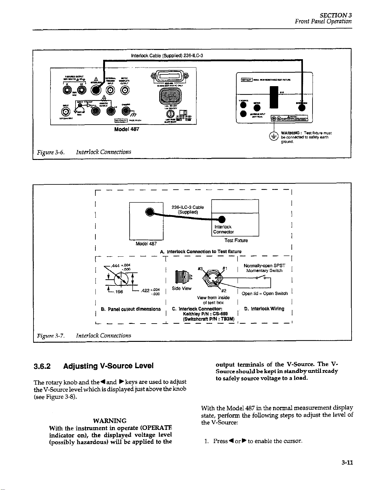
Interlock Cable ISUDDlied) 236ILC-3
F&ye 3-6. Interlock Connections
Front Panel Operation
SEC’UON 3
A Imerlock Connection 10 Test Sxture
c. l”wlclck co”“ectc.r:
Kelthley P/N : cs-659
(swnchcmfl PIN : TS3M)
,‘igure 3-7.
3.6.2
;-----T------,-----;
8. Pane, w,ovt dlmenslons
L------l-- ____ /__---I
Interlock Connections
Adjusting V-Source Level
The rotary knob and the 4 and b keys are used to adjust
the V-Source level which is displayed just above the knob
(see Figure 3-8).
WARNING
With the inshument in operate (OPERATE
indicator on), the displayed voltage level
(possibly hazardous) will be applied to the
0. merlock wmng
I
output terminals of the V-Source. The VSource should be kept in standby until ready
to safely source voltage to a load.
With the Model 487 in the normal measurement display
state, perform the following steps to adjust the level of
the V-Source:
1. Press 4
orb to
enable the cursor.
3-11
Page 60

SECTION 3
Front Panel Opemticm
Figure 3-8.
v-source Adjust
NOTE: For best accuracy, use the 5OV range to source
zk50.5v
or less.
Quick Zero
The Quick zero feature allows you to set the voltage
source of the Model 487 to OV with two key presses;
SHIFTand4or~key. Thevoltagesourcewillnot change
ranges. For example, with the voltage source level currently set to 100.5OV (5OOV range), pressing SHIFT and
the+ (or4 ) will set the voltage source to OV on the 500V
range (OOO.OOv). To return to the previously set voltage
source level, simply press SHIFT and w (or 4 ) again
The cursor is indicated by the flashing digit. Jf an adjust action does not occur in three seconds, the cursor
will disable.
2. Select the appropriate v-source range.
The position of the decimal point in the displayed VSource reading denotes the selected range. For example, a reading of OO.OOOV is OV on the 50V range,
while a reading of OCO.OOV is OV on the 500V range.
Ifonthe50Vrange,the500Vrangecanbeselectedby
pressing 4 until the displayed range changes. Conversely, to select the 50V range, press b until the
range change occurs.
3. Position the cursor on the digit to be adjusted.
The position of the cursor is controlled by the 4 and
b keys. Each press of the 4 key moves the cursor to
the next more significant digit. Each press of the b
key, moves the cursor to the next less significant
digit.
3.6.3
Preset
PRESET
El
OHMS
(VA)
preset allows the V-Source to be adjusted to a predetermined level at
the
touch of a single key. This feature
eliminates the tedious task of manually adjusting the VSource to a frequently used level.
Perform the following steps to preset a V-Source level:
1. Enable preset by pressing PRESET. The PRESET indicator will turn on.
2. Adjust the V-Source to the desired range and level
using the 4 and b keys, and rotary knob as previously explained.
3. Disable preset by again pressing PRESET. The volt;a;,;urce will return to the level it was previously
4. Adjust the voltage source 1eveL
The rotary knob is used to adjust the voltage source
level. Turning the knob clockwise increases the voltage level at the cursor position, and conversely, toming it counter-clockwise decreases the voltage level.
Cursor position determines how much the displayed value changes with each detent turn of the
knob. For example, with the cursor on the tenths
digit of the displayed value, each detent turn of the
knob will increase or decrease the value by 1 /lO volt
(10omv).
3-12
Whenever preset is enabled, V-Source will adjust to the
value set in step 2.
NOTES:
1. A preset V-Source level can be saved as the default
condition (see paragraph 3.8.6).
2. A preset V-Source value of OO.COOV is the factory default condition.
3. With the V-Source in operate, the output will immediately update to whatever voltage value is displayed (unless I-limit occurs).
Page 61

Front Panel Operation
SECTION 3
The Quick Zero feature can be used to set the Preset level
to ov as foIlows:
1. Enable Preset by pressing PRESET.
2. Perform Quick Zero (press SHIFT and then, (or4 ).
3. Disable Preset by again pressing PRESET. The voltage source will return to the previously set level.
3.6.4
The V-Source has current limit (I-limit) capabilities to
protect the instrument and external current sensitive cir-
cuitry from possible damage. The V-Source can be set for
an I-limit of 25p.A or 2.51x4.
When I-limit occus, the OPERATE indicator wiIl flash.
This indicates that the V-Source is no longer sourcing the
programmed voltage level to the load. For example, assume the V-Source is set to source 1OV to a 25Ok!J load
with I-limit set to 2Sfl. Based on Ohms Law, the current
through the load should be 40@ (lOV/25OkQ = 4Ow).
However, because the I-limit is set to 25&% the current
through the load will be 25@. The actual voltage applied
totheloadwillreally be625V (25OkQX25!.~A=6.25V)instead of the programmed 1OV. lf the 250k.Q load can handle 2.5mA without being damaged, then the I-limit could
be increased to 2.5mA to prevent I-limit from occurring.
Perform the foIlowing steps to set I-limit:
I-Limit
3.6.5 Operate
MO” 2mA
The OPERATE key toggles the output between standby
and operate. In standby, the V-Source is removed from
the rear panel output terminals. In operate (OPERATE
indicator on) V-Source is applied to the output terminals.
A flashing OPERATE indicator denotes that the V-Source
is in current limit as previously explained in paragraph
3.6.4.
CAUTION
A relay switch, in series with OUTPUT HI, is
opened when the V-SOURCE is placed in
standby. The transition to an open output
creates a potential for noise spikes. The open
output allows dielectric absorb&n to recharge capacitors to unexpected voltage levels.
3.6.6 Basic V-Source Operating
Procedure
The following procedure will summarize how to use the
V-Source as a separate, independent source. Using the VSource in conjunction with the pica-eter is covered in
paragraph 3.7 (V/I ohms measurements) and paragraph
3.15 (Source V Measure I). This procedure assumes that
the user is familiar with the operation of the basic VSource controls as previously explained.
Keep pressing and releasing MENU until the GUIrently selected I-limit is displayed:
Use the rotary knob, or 4 and b keys to display the
desired I-limit value.
To,enter the displayed I-limit, press MENU. The next
menu item will be displayed.
To exit the menu, press SHIFT and then EXIT in that
order. The instrument will return to the normal
measure display state.
Perform the following steps to use the V-Source:
1.
With the V-Source in standby (OPERATE indicator
off), connect the load to the V-Source output terminals as shown in Figure 3-9.
Use the rotary knob, 4 and b the keys to set the de-
2.
sired voltage range and level. Note that if previously
set, a preset value can be used by enabling preset.
3.
Select the appropriate I-limit (25@ or 2.5m.4).
4.
Press OPERATE. The OPERATE indicator will turn
on to denote that the displayed voltage level is available at the output terminals.
5.
To disable the V-Source, again press OPERATE. The
OPERATE indicator light will turn off.
3-13
Page 62

SECTION 3
Front Panel Operation
Model 487
Figure 3-9. Basic V-Source Connections
3.7 V/I OHMS MEASUREMENTS (Model 487)
By using the V-Source in conjunction with its picoammeter, the Model 487 can make resistance measurements
as high as 50.5 x lO”9.. With V/I ohms selected, the resis-
tance is automatically calculated from the applied voltage and measured Current (R = V/D and displayed (in
ohms) on the Model 487. A& resolution of the resistance measurement depends on the s&&d current
Rage.
The V/I ohms function is enabled by pressing SHIFT and
then OHMS. The display will toggle to the resistance (.Q)
measurement state. To disable V/I ohms, again press
Sm and then OHMS. The display will return to the
normal amps measurement state.
Perform the following steps to make V/I ohms measure
mentsz
1. Turn on the Model 487 and allow it to warm up for
two hours to achieve rated accuracy.
2. Disable the V/I ohms function, if it is currently selected.
3. With zero check enabled and the V-Source in
standby, connect the circuit shown in Figure 3-10.
The Keithley Model 8002A test fixture is shown because it is ideally suited for V/I ohms measurements
of Z-terminal devices.
4. Select a current range that gives the nearest full scale
reading or autorange, and perform zero correction
by pressing SHBT and then CORRECT.
5. Set the V-Source to the desired voltage level.
6. Press OPERATE to tom on the source output, and
disable zero check. The current measurement willbe
displayed.
7. Enable V/I ohms by pressing Sm and then
OHMS. The resistance measurement will be displayed in ohms (Q).
8. To measure from a baseline resistance, enable rel
while in V/I ohms.
3-14
Page 63

Front Panel Operation
SEClTON 3
L-----------’
Model 8002A
‘igure 3-10. V/l Ohms Connections (Source V Measure 1)
To make V/I ohms measurements, the Model 487 is configured to source voltage and measure current (Source V
Measure I). The V/I feature simply performs the calculation (R = V/I) and displays the resistance reading in
ohms. The results of any source V measure I test can be
converted to resistance by using the V/I ohms function.
Paragraph 3.15 expands on tests that source voltage and
measure
current, and provides some examples that are
particularly applicable to the V/I ohms function.
CAUTION
To prevent damage to the instrument, ad-
here to the following precautions when
floating the input above chassis ground:
1. Do not connect ANALOG OUTPUT LO
to CHASSIS. If there is a ground lii installed at the rear panel binding posts, re-
move it.
2 Make sure that any monitoring ins&w
ment connected to the analog output is float-
tng.
Paragraph 3.16.8 explains the precautions for
floating measurements in more detail.
3-15
Page 64

SECTION 3
Front Panel Operation
NOTES:
1.
Do not use zero check while in V/I ohms. Doing so
will blank the display (i.e. ” KU’) and cause the
ZERO CHECK indicator to flash.
Placing the V-Source in standby while in V/I ohms
2.
will result with zeroes being displayed (i.e.
I6-U.
The minus (-1 sign is not disabled in V/I ohms. Po-
3.
larity changes during a test could indicate charge/
discharge effects of the DUT. For example, a DUT
may behave as a capacitor. At a certain voltage the
capacitor will charge and display some positive resistance reading. If the V-Source is decreased, the capa&or will discharge causing current to flow in the
opposite direction. A negative resistance reading
will then be displayed.
4.
If a current Rel baseline exists (REL indicator on
while displaying current measurements) when V/I
Ohms is selected, resistance is calculated as follows:
0.00000
R=&
where: I is the actual current.
IO is the current rel baseline level.
Optimiziig Accuracy
When using V/I ohms, the V-Source range and current
range should be set up to optimize accuracy. In most
cases, it is best to use the maximum voltage possible and
set the current range accordingly. The instrument should
be placed in the most sensitive range possible without
causing an overranged condition. Doing so will optimize
the measuement for resolution and accuracy.
Autoranging can facilitate range selection.
ing material (such as Teflon@) for terminal connections
in custom-built test fixtures.
The current Rel feature provides a way to compensate for
leakage resistance which cannot be eliminated from the
test fixture. If the DUT (device under test) is removed
from the test fixtwe and then the test voltage is applied to
the fixture, the resulting Current will be entirely due to
the leakage resistance. Using Rel (while in the current
function) will “eliminate” this leakage current. Then with
the DUT in the test fixture, the current used for the V/I
ohms calculation will be entirely due to the DUT.
NOTE
Paragraph 3.16 contains additional considerations that must be addressed when making
current measurements.
3.8 MENU
The menu items are listed in Table 3-8. In general, each
press of the MENLJ key displays a menu item in the order
shown in the table. The available selections of the displayed menu item are selected and displayed with the ro-
tary knob or the4 and b keys. The selected option of the
displayed menu item is entered by again pressing
MENU. To exit the menu, press SHIFT and then EXIT.
The following information wiIl provide the detailed
steps for selecting the available options of the menu item
program.
3.8.1 Data Store
V/I ohms measurements tend to be more accurate when
current measured is close to full scale. Disadvantages of
operating with higher voltages include power dissipa-
tion in the DUT and voltage coefficient of high impedance DUT.
Leakage Resistance
There ,are cases where leakage resistance could adversely
affect V/I ohms measurements. For example, test fixture
leakage paths may appear in parallel with the device being measured, introducing errors into the measurement.
These errors can be minimized by using proper insulat-
3-16
This menu item is used to arm the data store and select
the number of readings to store in the buffer. Details for
using the data store is contained in paragraph 3.11.
Data Store Selections:
NO Do nothing
YES Arm data store
BUl%ERSIZE
BUFFERSIZE 001512 RDGS Number of
ODD RDGS
Wraparound
operation (circular buffer)
readings to
store in buffer
Page 65

Front Panel Opration
SECTION 3
Table 3-8.
Menu Item Description
DATA STORE
DATA RFXL
nlMrr
INTEGRATE
IEEE-488
DEFAULTS
SELETEST
DEBUG
CALIBRATE
CAL v SRC
Perform the following steps to arm the data store and set
buffer size:
1. Press and release MENU until the folkxving message is displayed:
DATA STORE NO
NO indicates that the data store is not armed. If you
are not going to store readings, exit the menu by
pressing SHIFT and then EXlT.
2. Use the rotary knob or the 4 and b keys to display
the following message:
DATASTORE YES
Arm data store and set buffer size
Recall data stored in buffer
Set current limit; 25yA or 2.5mA
(Model 487 only)
Set integration period; fast or line
cycle (50 or 6OHz)
Set IEEE-488 address O-30 or select
Talk-only
Save steps as power-up defaults,
rehxn to previously saved defaults, or return to factory defaults
Test display and memory elements
Troubleshooting mode
Calibrate current range
Calibrate V-Source (Model 487
only)
MENU Items
5. With the desired buffer size value displayed, press
MENU. The instrument will exit the menu and wait
for a tigger to start the storage process as shown in
the following example:
-.-----d”
The I’*” indicates that tlw data store is armed, and the
flashing TRIGGER indicator denotes that the ins!zrument is waiting for a trigger.
NOTE: when setting buffer size, you cannot increase a
selected digit that will cause the value to exceed 512. For
example, if the present value is 428 with the cursor on the
“4”, you cannot increase it to a “5” since 528 is invalid. To
increment the value 428, the cursor must be on the “2” or
the ‘8”.
3.8.2
This menu item is used to recall data that is stored in the
buffer using the data store. Details for using the data
store is contained in paragraph 3.11.
Data Recall Selections:
Data Recall
NO
YES
LOC 001-512
LOCMIN
LOCMAX
Disable data recall
Enable data recall
Stored reading at displayed
buffer location
Minimum reading stored in
buffer
Maximum reading stored
in buffer
3. To arm the data store, press MENU. T’ne following
message will appear on the large display:
BIJFFERSIZE
On the small display, the last progmmmed size
value will be displayed.
4. Use the ADJUST controls to display the desired
value. The 4 and b keys position the cursor on the
digit to be adjusted and the rotary knob increments
or decrements the value from the selected digit. For
example, to store 236 readings in the buffer, adjust
the value to the following display message:
BUFFERSIZE 236 RDGS
Perform tlw following steps to recall data stored in the
data store buffer:
1. Press and release MENU until the following message is displayed:
DATA RECL
NO indicates that data recall is disabled. If you do
not wish to examine stored readings, proceed to step
5.
2. Use the rotary knob or the 4 and b keys to display
the following message:
DATA RECL
NO
YES
3-17
Page 66

SECTION 3
Front Panel Operation
Press MENU. The stored reading at memory location 001 will be displayed. For example, if the stored
reading is -l.OOOOOmA, the following will be displayed:
-1.00000 rd.
LOC 001
The stored readings at the other memory locations
(and MIN and MAX) can be examined by using the
ADJUST controls. The4 and b keys position the cursor on the digit to be adjusted and the rotary knob increments or decrements the memory location nunher from the selected digit. Decrementlng the value
from 001 displays the maximum and minimum
readings.
To exit from data recall press MENU to display the
next menu item, or press SHIFI and then EXIT to exit
from the menu.
NOTES:
1. The message “NO DATA” on the small display, indicates that there are no readings stored in the buffer.
2. Turning off power, performing factory initialization,
defaultsrecallorsendinga DCLorSDC overthebw,
clears the buffer (NO DATA).
3.8.3
I-Limit (Model 487)
3. Enter the displayed I-limit by pressing MENU. The
next menu item will be displayed.
4. To exit from the menu, press SHIFT and then EXIT.
The instrument will return to the normal measurement display state.
3.8.4 Integration
This menu selection is used to check or change the integration period for A/D conversions.
Integration Period Selections:
FAST
LINE6OHZ
LINE5OI-u
The selectable integration periods offer a trade-off between speed, resolution and noise rejection. The fast integration period provides the fastest measuements and
should be used when speed is the most important consideration. The line cycle integration periods provide slower
but more stable (quieter) measurements by rejecting
power line noise. To achieve the most stable measurements, select the line cycle period that matches the available line frequency.
1.6msec integration (4-l /2 digit
resolution)
Line cycle 06.67msec) integration (5-l/2 digit resolution)
Line cycle (20msec) integration
(5-l /Z,digit resolution)
This menu item is used to check or change the current
limit setting of the V-Source of the Model 487. Details on
I-limit is contained in paragraph 3.6.4.
I-Limit Selections:
2.5mA I-limit setting of 2.51~4
25~
I-limit setting of 25+4
Perform the following steps to check or change the Ihit:
Press and release MENU until the currently selected
I-limit is displayed. For example, if I-limit is 25pA,
the following message will be displayed:
ILmm-
2-w.
To retain this I-limit setting, proceed to step 3 or 4.
Use the rotary knob or the 4 and b keys to display
the alternate I-limit.
Perform the following steps to check or change the in&
gration period:
1.
Press and release MENU until the currently selected
integration period is displayed. For example, if the
integrationperiodiscurrentlysetfor60Hzlinecycle,
the following message will be displayed:
JNTEGRATE
LINEXOHZ
To retain this integration period, proceed to step 3 or
4.
2.
Use the rotary knob or the 4 and fi keys to display
the desired integration period.
3.
Enter the displayed integration period by pressing
MENU. The next menu item will be displayed.
4.
To exit the menu, press SHIFI and then EXIT. The instrumentwill return to the normal measurement display state.
NOTE: Menu selection DEFAULT SAVE (see paragraph
3.8.6) can be used to save the selected integration period
as the power-up default condition.
3-18
Page 67

Front Panel Operation
SECTION 3
3.8.5
This menu item is used to check or change the IEEE-488
address, or select talk-only.
IEEE-488 Selections:
At the factory, the IEEE-488 address is set to 22. However,
it can be set to any valid value from 0 to 30. Section 4 contains detailed information on IEEE-488 programming. In
talk-only, the instrument will continually output data to
a listening device, such as a listen-only printer. Details on
using talk-only are contained in paragraph 3.13.
Perform the following steps to chedc or change the
IEEE-488 address, or select talk-only:
1.
Press and release MENU until the current IEEE-488
selection is displayed. For example, if primary address 22 is currently selected, the following message
will be displayed:
To retain this selection, proceed to step 3 or 4.
IEEE-488 Address or Talk-Only
ADDR 00-30
TALKONLY
IEEE-488
IEEE-488 primary address
talk-only mode
ADORE!
Default Selections:
OK Do nothing
SAVE
RECALL Retun to previously saved powerFACTORY Return to factory default conditions
Perform the following steps to use a default selection:
Press and release MENU until the following mes-
1.
sage is displayed:
DEFAULTS
If you do not wish to execute one of the other default
selections, proceed to step 3 or 4.
2.
Use the rotary knob or the 4 and W keys to display
the desired default selection.
Execute the displayed default selection by pressing
3.
ENTER. If “OK” or “SAW” is executed, the next
menu item will be displayed. If “RECALL” or “FAC-
TORY” is executed, the instrument will return to the
normal measurement display state.
If still in the menu, you can exit from it by pressing
4.
SHIFT and then EXIT.
Save present operating states as
power-up default conditions
up default conditions
and save as power-up default con-
ditions.
OK
2.
Use the rotary knob or the 4 and F keys to display
the desired address or talk-only.
Enter the displayed selection by pressing MENU.
3.
The next menu item will be displayed.
4.
To exit the menu, press SHm and then FXIT. The instrument will return to the normal measurement display state.
NOTE The instrument will power-up to the last selected
IEEE-488 selection.
3.8.6 Defaults
This menu item allows you to save the present operating
states as the power-up default conditions, or to return the
instrument to previously saved default conditions, or to
return the instrument to the factory default conditions.
Factory default conditions are listed in Table 3-3. Also in-
dicated in the table are the controls/features that can be
saved as the power-up default conditions.
3.8.7
This menu item is used to test display segments and in-
ternal memory elements. During the display test, each
segment of all the LEDs will be briefly displayed. Then,
all segments of each LED will be sequentially displayed.
The display test takes approximately 17 seconds to complete. After the display test, tests on its memory elements
will be performed.
Self-Test Selections:
Perform the following steps to perform the self-test:
1. Press and release MENU until the following mes-
Self-Test
NO
YES
sage is displayed:
SELFlXST
Do not perform self-test
Perform self-test
NO
3-19
Page 68

SECTlON 3
Front Panel Operation
lfyoudonottishtoruntheself-test,proceedtostep
5.
Use the rotary knob or the 4 and b keys to display
the folkwing message:
SELFTEST YES
To run the test press MENU. After the display test is
completed, tests on its memory elements will be per-
formed while the following message is displayed:
SELFJXST
Tests on its memory elements takes approximately
five seconds. If the tests pass, the next menu item will
be displayed. In the event of a failure, one of the following messages will displayed.
ROM ERROR
RAM ERROR
The error message can be canceled by pressing any
front panel key. However, a problem existsand must
be resolved. Refer to the troubleshooting informa-
tion in
To exit from the menu, press SHIFT and then FXT.
The instrument will return to the normal measurement display state.
3.8.8
The debug menu item locks the A/D converter in one of
three multiplexer state to allow signal tracing through
the inswument during troubleshooting. Refer to paragraph 7.7 for details on using this feature.
Section 7.
Debug
3.9 FRONT PANEL TRIGGERING
TRIGGER
SETUP
q
TRIGGER
q
r
The following paragraphs discuss front panel triggering,
trigger mode selection, trigger interval, trigger delay and
trigger source.
3.9.1
The Model 486/487 may be operated in two basic trigger
modes; one-shot
separate trigger is required to initiate each reading. For
the multiple mode, however, only a single trigger is required, with conversion rate determined by the pro-
grammed trigger interval. The multiple trigger mode is
the factory default, however, the one-shot mode can be
saved (see paragraph 3.8.6) as the power-up default.
To check or change the selected trigger mode, proceed as
follows:
Trigger Mode
and multiple. In the one-shot mode, a
Ifyoubaveinadvertentlyselected debug,pressMENU to
display the next menu item, or press S-IIFT and then
EXIT to exit the menu.
3.8.9
The calibrate program is used ~to calibrate the current
ranges of the Models 486 and 487. Refer to paragraph 7.3
to calibrate the instrument.
3.8.1.0
This program is used to calibrate the V-Source of the
Model 487. Refer to paragraph 7.3 to calibrate the VSource.
3-20
Calibrate
Cal V SRC (Model 487)
1.
Press SETUP to enable trigger setup (SETUP indicator turns on). The currently selected trigger mode
will be displayed. For the multiple mode, the following will be displayed:
TRIG MODE
For the oneshot mode, the following will be dis
played:
TRIG MODE
2.
To toggle the displayed trigger mode use the rotary
knob or the 4 and b keys.
3.
Select the displayed trigger mode by pressing
SETUP to display the next trigger setup selection
(trigger interval), or by pressing SHIFT and then
SETUP to exit trigger &up.
MULTIPLE
ONE-SHOT
Page 69

Front Panel @eration
SECTION 3
3.9.2
The trigger interval determines the time period between
individual readings when the instrument is in the multi-
ple trigger mode. Interval also affects the storage rate of
the data store.
The trigger interval can be set from ZOmsec to 999.999sec.
A trigger interval of 175msec is the factory default condition. However, any valid trigger interval can be saved
(see paragraph 3.8.6) as the power-up default.
Trigger interval speeds from 1Omsec to 49msec can only
be achieved using the data store. Otherwise, an interval
of 5Omsec or the programmed interval (whichever is
greater) will be used.
Perform the following steps to check or change the selected trigger interval:
Trigger Interval
NOTE
Trigger interval cannot be set in the one-shot
trigger mode.
conversion, with the instrument waiting the programmed delay time after each trigger before taking a
reading. For example, if you program a 3OOmsec trigger
delay, the unit will wait 3L%nsec after each trigger before
taking a reading.
TheMode1486/487canbeprogranunedforadelayintervalfromOsecto999.999secin Ims&.ncremenk. A trigger
delay of Osec is the factory default; however, any valid
trigger interval can be saved (see paragraph 3.8.6) as the
power-up default.
NOTE
If a trigger occurs during the trigger delay pexiod. the txizzer overrun (TRG OVERUN) error &ssag~%ll be displa&d. The tigger that
caused the error will be ignored.
Perform the following steps to check or change the trigger delay period:
1.
Press and release SJZTUP until the trigger delay is
displayed. For example, if the trigger delay is set for
Osec (factory default), the following will be displayed:
Press and release SETUP until the trigger interval is
displayed. For example, if the trigger interval is set
for 175msec (factory default), the following will be
displayed:
TlUGINTVL 000.17~
To retain the displayed trigger interval, proceed to
step 3.
Use the4 and b keys, and the rotary knob to display
the desired value. The4 and, keys position the cursor on the digit to be modified, and the rotary knob
increments/decrements the value from the selected
digit.
Select the displayed trigger interval by pressing
SETUP to display the next trigger setup selection
(trigger delay), or by pressing SHIFT and then
SETUP to exit trigger setup.
3.9.3
Trigger delay is the time from the trigger point until the
unit takes a readiig. In the multiple trigger mode, the delay period affects only the first conversion; however, in
the one-shot bigger mode, the delay period affects every
Trigger Delay
TRIG DELAY 000.~0
To retain the displayed trigger delay, proceed to step
3.
2.
Use the4 and, keys, and the rotary knob to display
the desired value. The4 and, keys position the cursor on the digit to be modified, and the rotary knob
increments/decrements the value from the selected
digit.
3.
select the displayed bigger delay by pressing
SETUP to disc&w the next tieeer setup selection
bigger sourch’or by pressi;;gu SHE+ and then
SETUP to exit trigger setup.
3.9.4 Trigger Sources
For front panel operation, there are three trigger sources
available; front panel TRIGGER key, the EXTERNAL
TRIGGER INPUT jack, and the OPERATE key for the V-
Source of the Model 487.
With the external trigger source selected, a trigger pulse
applied to the rear panel EXTERNAL TRIGGER INPUT
jack will trigger the insbunent (see paragraph 3.10.1 for
3-21
Page 70

SECTION 3
Front Panel Operation
details). With the operate trigger source selected, a trigger will occur when the V-Source of the Model 487 is
placed in operate. The front panel TRIGGER key is always enabled, regardless of the selected trigger source;
however, this key is locked out when the instrument is in
remote.
Additional trigger sources include IEEE-488 X, GET, and
talk commands, as discussed in section 4.
The external bigger source is the factory default; however, any of the other trigger sources can be saved (see
paragraph 3.8.6) as the power-up default condition
Perform the following steps to check or change the trigger source:
1.
Press and release SETUP until the currently selected
bigger source is displayed. If external trigger source
is selected, the following will be displayed:
TRIG SRC
-AL
The other available trigger source selections:
TRIG SRC OPERATE
TRIG SRC
BUS X
TRIGSRC GET
TRIG SRC
TALK
TRIG MODE MULTIPLE
Press SETUP and use the 4 and b keys, and rotary
knob to set a trigger interval of three seconds as follows:
TRIG
lNTE 003.000
Press SHIiT and then SETUP. The instrument will
return to the normal measurement display state. The
display will update with a new reading every three
seconds as indicated by the trigger status LED (flashing decimal point) that follows the reading.
Example 2:
One-shot trigger mode with a one second trigger delay:
1.
Press SETUP (SETUP indicator turns on) and use the
rotary knob (if necessary) to display the one-shot
trigger mode as follows:
TRIG MODE
2.
Press SETUP and use the 4 and b keys, and rotary
ONE-SHOT
knob to set a trigger delay of one second as follows:
TRIG DELAY WI.OW
To retain the displayed trigger delay, proceed to step
3.
2.
Use the 4 and b keys, or the rotary knob to display
the desired trigger source.
3.
Select the displayed trigger source selection by
pressing SETUP’. The instrument will return to the
normal measurement display state.
3.9.5
Trigger Examples
Example 1:
Multiple trigger mode with a three second interval be-
tween readings:
1. Press SETUP (SETUP indicator turns on) and use the
rotary knob (if necessary) to display the multiple
trigger mode as follows:
3-22
3.
Press SHIFl- and then SETUP. The instrument will
return to the normal measuremfzit display state.
4.
To initiate a single reading, press TRIGGER. Note
that the display updates after a delay of approximately one second.
5.
Quickly press TRIGGER twice. The second press of
TRIGGER causes a trigger ov- error. The
mes-
sage “TRG OVERLJN” is displayed. The invalid trigger, which occurred during the delay period, is ig-
I-LOEXi.
3.10 EXTERNAL TRIGGERING
The Model 486/487 has two external BNC connectors on
the *ear panel associated with instrument triggering (see
Figure 3-11). The EXTERNAL TRIGGER INPUT comw-
tor allows the instrument to be triggered by other devices,whiletheMETERCOMPLETE OUTl’UTcom~ector
allows the instrument to trigger other devices
Page 71

Figure 3-11. Trigger Connectors
3.10.1 External Trigger
The external trigger input requires a falling edge pulse at
TI’L logic levels, as shown in Figure 512. Connections to
the rear panel EXTERNAL TRIGGER INPUT jack should
be made with a standard BNC connector. If the in&ument is in theexternal higgersourcemode, itwillbe triggered to take readings while in either a multiple or oneshot trigger mode when the negative-going edge of the
external trigger pulse occurs.
Front Panel Operation
SECTION 3
3.10.2 Meter Complete
The Model 486/487 has an available output pulse that
can be used to trigger other instrumentation. A single
Tn-compatible negative-going pulse (see Figure 3-13)
will appear at the METER COMPLETE OUTPUT jack
each time the instrument completes a reading. To use
ter complete output, proceed as follows:
1. Connect the Model 486/487 to the instrument to be
triggered with a suitable shielded cable. Use a standard BNC connector to make the connection to the
Model 486/487.
2. Configure the Model 486/487 to make the desired
measurements.
3. In the multiple trigger mode, the instrument will
output pulses at the conversion rate; each pulse wiLl
occur after the Model 486/487 has completed a conversion.
4. Intbeone-shottriggermode,theMode1486/487wiU
output a pulse once each time it completes a reading
after being triggered.
me-
, .Qure 3-72. Extend Trigger Pulse Specific&ions
To use the external trigger, proceed as follows:
1. Connect the external trigger source to the rear panel
BNC EXTERNAL TRIGGER INKIT connector. The
outer shell (shield) of the connector to digital com-
mon
2. Place the instrument in “one-shot on external triggei’ or “multiple on external trigger” as explained in
paragraph 3.9.
3. To trigger the instrument, apply a pulse to the external trigger input. The instrument will process a single reading each the the pulse is applied (one-shot),
or start multiple readings.
NOTE
Triggering the unit while it is processing a
reading
from
a previous trigger will cause a
trigger overrun (TRG OVERUN).
LSTTLLOW 1 1
fO.25V Tvoical) I I
Figure 3-13. Meter Complete Specifimfions
3.11 DATA STORE
The data store can store up to 512 readings for later recall.
Data can be stored at specific intervals of between 1Omsec
and 999.999sec with lmsec increments. In addition, oneshot extemalorfrontpaneltriggeringcanbeused tostore
data at arbitrary points in time.
The following paragraphs describe front panel operating
procedures for stoxing and recalling data.
3.11.1 Storing Data at Programmed
Intervals
Use the following procedure for storing data at defined
intervals:
3-23
Page 72
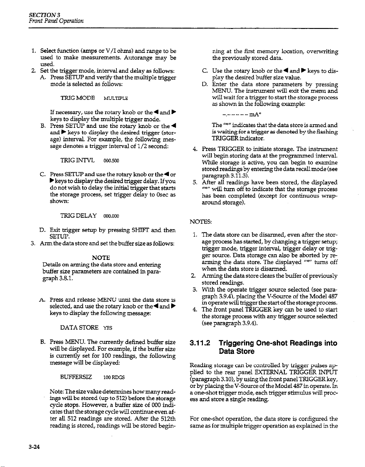
SECTlON 3
Front Panel Operation
1.
Select function (amps or V/I ohms) and range to be
used to
make
measurements. Autorange may be
- .
used.
Set the trigger mode, interval and delay as follows:
2.
Press SETUP and verify that the multiple trigger
A.
mode is selected as follows:
TRIGMODE ~~JLTIPLE
If necessary, use the rotary knob or the 4 and b
keys to display the multiple trigger mode.
B.
Press SETUP and use the rotary knob or the 4
and b keys to display the desired trigger (storage) interval. For example, the following message denotes a trigger interval of l/2 second:
TRlG
INTVL 000.500
Press SETUP and use the rotary knob or the4 or
C.
b keys to display the desired trigger delay. If you
do not wish to delay the initial trigger that starts
the storage process, set trigger delay to Osec as
shown:
ning at the first memory location, overwriting
the previously stored data.
C.
Use the rotary knob or the 4 and b keys to display the desired buffer size value.
D.
Enter the data store parameters by pressing
MENU. The instrument will exit the menu and
will wait for a trigger to start the storage process
as shown in the following example:
-.-----tie
The “*” indicates that the data store is armed and
is waiting for a trigger as denoted by the flashing
TRIGGER indicator.
4.
Press TRIGGER to initiate storage. The instrument
will begin storing data at the programmed interval.
While storage is active, you can be@n to examine
stored readings by entering the data recall mode (see
paragraph 3.11.3).
5.
After all readings have been stored, the displayed
“v’ wiIl turn off to indicate that the storage process
has been completed (except for continuous wraparound storage).
TRIG DELAY
Exit trigger setup by pressing SHIFI and then
D.
oo0.000
SETUP.
Arm the data store
3.
and
set the buffer size as follows:
NOTE
Details on arming the data store and entering
buffer size parameters are contained in para-
graph 3.8.1.
A.
Press and release MENU until the data store is
selected, and use the rotary knob or the4 and k
keys to display the following
DATA STORE
Press MENU. The currently defined buffer size
B.
YES
message:
will be displayed. For example, if the buffer size
is currently set for 100 readings, the following
message
will be displayed:
BUFFFRSIZ 100 RDGS
Note:Thesizevaluedetermineshowmanyreadings wi!J be stored (up to 512) before the storage
cycle stops. However, a buffer size of 000 indicates that the storage cycle will conhue even after all 512 readings are stored. After the 512th
reading is stored, readings will be stored begin-
NOTES:
1.
The data store can be disarmed, even after the storage process has started, by changing a trigger setup;
trigger mode, trigger interval, trigger delay or trigger source. Data storage can also be aborted by rearming the data store. The displayed “w’ turns off
when the data store is disarmed.
2.
Arming the data store clears the buffer of previously
stored readings.
3.
With the operate trigger source selected (see paragraph 3.9.4), placing the V-Source of the Model 487
inoperatewilltrigger thestartof thestorageprocess.
4.
The front panel TRIGGER key can be used to start
the storage process with any trigger source selected
(see paragraph 3.9.4).
3.11.2 Triggering One-shot Readings into
Data Store
Reading storage can be controlled by bigger pulses applied to the rear panel EXTERNAL TRIGGER INMIT
(paragraph 3.10), by using the front panel TRIGGER key,
or by placing the V-Source of the Model 487 in operate. In
a one-shot trigger mode, each trigger stimulus will process and store a single reading.
For one-shot operation, the data store is configured the
same
as for multiple trigger operation as explained in the
3-24
Page 73

previous paragraph. Only the trigger setup is different.
The trigger mode is set for one-shot (TRIG MODE ONESHOT), and the trigger source is set for external U’RG
SCR EXTERNAL) or operate U-RG SRC OPERATE).
In the one-shot mode, each press of the TRIGGER key
will cause a single reading to be processed and stored in
thebuffer.ThefTontpanelTRIGGERkeyisactiveregardless of the trigger source sekxiion. With the external big-
ger source selected (TRIG SRC EXTERNAL), each trigger
pulse applied to the unit (see paragraph 3.9.4) will process and store a single reading. With the operate trigger
source selected (TRIG SRC OPERATE), a single reading
will be processed and stored each time the Model 487 VSource is placed in operate.
NOTES:
Front Panel Operation
4.
To access a reading at a particular memory location,
use the4 and, keys to position the cursor on the desired digit and use the rotary knob to adjust the location value from the selected digit.
5.
To
exit
data recall, press SHIFT and then EXIT.
NOTES:
1. If the data store has no valid data to display, the following message will appear in the small display
upon entry into data recall:
NO DATA
2. The instrument will continue to store data while in
data recall until the data store buffer is full (unless in
wrap-around operation).
SECI’ION3
1.
Trigger interval cannot be set when in the one-shot
trigger mode.
2.
Triggerdelay can besetintheoneshottriggermode.
Each time the trig@r stimuh.~~ occurs, the reading
and storageprocesswillnot occuruntilthedelayha
expired.Anytriggersthatoccurduringthedelayperiod will result in a trigger overrun error URG
OVERUS. The invalid trigger(s) will be ignored.
3.11.3 Recalling Data
Data can be recalled either during storage or after storage
is complete by using the following procedure:
Press and release MENUuntil data recall is selected,
and use the rotary knob or the <and> keys to display
the following message:
DATARECL YES
PressMENUThereadingstoredinthefirstmemory
location will be displayed. For example, if a 1mA
reading is stored in location 001, the following mes-
sage will be displayedz
1.ooom mA Lot 001
For sequential access, use the rotary knob. Turning
the knob cow.ter-&xkwise will display the maximum (LOC MAX) and minimum readings stored in
thebuffer.Turrdngtherotaryknob clockwisewillincrement buffer locations until the last buffer location
is reached.
3.12 ANALOG OUTPUT
The Model 486/487 has a non-inverting ZV analog output. ANALOG OUTPUT connections are shown in
Figure 3-14. For a ZOO,CPXI count input, the analog output
will be ZV. Typical examples are shown in Table 3-9.
The output resistance of the analog output is lOOR. To
minimize the effects of loading, the input impedance of
the device connected to ANALOG OUTPUT should be as
high as possible. For example, for a device with an input
impedance of IOkQ, the error due to loading will be approximately 1%. Rel has no effect on the analog output. A
1mA input (2mA range) will result in a 1v analog output
whether Rel is enabled or not.
CAUTION
To prevent damage to the imtmnent, adhere to the following precautions when
floating the input above chassis ground:
1. Do not connect ANALOG OUTPUT LO
to CHASSIS. If there is a ground link installed at the rear panel binding posts, remove it.
2 Make sure that any monitoring ins&ument connected to the analog output is float-
Paragraph 3.16.8 explains the precautions for
floating measurements in more detail.
3-25
Page 74

SECTION3
Front Panel Operation
L----------J
Equivalent Circuit
Meas”ri”g Device (Rr)
(i.e. Ghan Recorder)
?gure 3-14. Typical Analog Output Connections
Table 3-9.
Typical Analog Output Values
3-26
Page 75

Front Panel Operation
SECTION 3
3.13 TALK-ONLY
In talk-only, the Mode1486/487 will talk continuously on
the IEEE-488 bus and output readings to a listen-only device whenever a measurement conversion occurs. For example, in talk-only, measurement readings
Model 486/487 will be tiansmitted to a listen-only
printer that is connected to the IEEE-488 bus. Bus connections are covered in paragraph 4.4 of Section 4. While using talk-only, a controller cannot be connected to the
IEEE-488 bus.
The listen-only device will not slow down the Model
486/487 measurement rate. For example, after the buffer
of a listen-only printer fills, the printer will only accept
readings
from
the Model 486/487 at its print rate. The
Model 486/487 continues to take readings at its programmed rate, but sends them only as fast as the printer
can accept them.
Perform the following steps to place the Model 486/487
in talk-only:
1.
Press and release MENU until the present IEEE488
selection is displayed. For example, if the IEEE-488
busaddressissetto22, thefollowingmessagewillbe
displayed:
IEEE-488
2.
Use the rotary knob, or the W button to display talk-
ADDR 2.2
only a.5 follows:
from
the
3.14 OPERATING EXAMPLES
3.14.1 Measuring Current Generated by
an LED
A standard light emitting diode (LED) will generate
small currents (nanoampere region) when exposed to
light. This operating example will use the Model 486 or
487 to measure the current generated by an LED over a
range of light intensity, and store the readings in the data
store.
Equipment needed:
1 LED
1 Model 237-ALG-2 Alligator Cable (supplied)
Procedure:
NOTE
Step 1 will return the instrument to factory default conditions. In that state, filter will be enabled (DIG+AN), zero check will be enabled,
and autorange wilI be enabled.
1.
Perform the following steps to perform factory initialization:
A. Press and release MENU until the following
message is displayed:
DEFAULTS
OK
IEEE-488
To enter the talk-only mode, press MENU. The
3.
TALKONLY
TALK indicator will turn on.
4.
Exit the menu by pressing SHIFI and then EXIT. The
instrument will return to the normal measurement
display state. Each measurement conversion will be
sent over the bus.
NOTE: If the reading source is currently set to Bl (data
store readings)
from
previous IEEE-488 operation (see
paragraph 4.2.2 in Section 4), a data store dump to a listen-only device can be performed by placing the instrument in talk-only. If the instrument is in talk-only while
data storage is in progress, each reading will be sent to
the listen-only device at the programmed interval. If the
instrument is placed in talk-only after the data storage is
complete, all the stored readings will be sent to the listen-
only device as fast as it will accept
them.
B. Use the rotary knob to display the following
message:
DEFAULTS
FACTORY
C. Press MENU to perform factory initialization.
2.
Connect the LED to the Model 486/487 as shown in
Figure 3-15.
3.
Zero correct the Model 486/487 by pressing SHIFT
and then CORRECT.
Place the LED, with the test cable connected to it, in a
4.
dark place (i.e. desk drawer, or a in a box).
5.
Disable ZERO CHECK.
6.
Verify that the reading on the display is around 1 pA
or less. The LED should generate virtually OA in a
daik environment.
7.
Configure the data store of the Model 486/487 as follows:
A. Press and release SETUP until the trigger inter-
val is displayed. Use the 4 and b keys, and the
3-27
Page 76

SECTION 3
Front Panel Operation
rotary knob to display an interval of l/2 seconds
as follows:
TRIG
INTVL 000.500
Enter the displayed trigger interval by pressing
B.
SHET and then SETUP.
Press hD3VU and use the rotary knob to display
C.
the following message:
DATASTORE YES
Press MENU and use the&md, keys to display
D.
a buffer size of 50 readings as shown:
BUFFERSIZE
Arm the data store by pressing MENU. The
E.
0.50~0~s
“data store armed” indicator (9 wilI be dis-
played.
NOTE
When triggered, the data store will store 50
readings at an interval rate of l/2 seconds.
This will give you approximately 25 seconds
to move the LED gradually from the dark environment to a bright light sowce (lamp or
flashlight).
11. Perform the following steps to recall stored data:
A. Press and release MENU until the following
message is displayed:
DATARJXL
NO
5. Use the rotary knob to display the following
message:
DATARECL Y?Z?
C. Press MENU. The first reading (at memory loca-
tion 001) will be displayed. Since this measurement was performed in the dark, the following
reading could result:
0.00074 Illi Lot 001
D. Examine the readings stored in the other mem-
ory locations by using the rotary knob. Turning
the knob clockwise increments the memory locations. Turning the knob counter-clockwise past
location 001 displays the minimum and maximum readings stored in the buffer. For this test,
the following
maximum and minimun readings
could result
022.106 nA
-0.36250 nA LOClV5V
LCChJAX
8.
To start the data storage process, press the flashing
TRIGGER kev.
9.
After allowing a few seconds to acquire readings in
the dark environment, gradually move the LED
fromthedarktowardsabrightlightsouxe.Timethe
transition from dark to bright light such that the last
few seconds of data storage are performed at peak
light conditions.
10.
Data storage will be complete when the displayed
“W’ turns off.
12 To disable data recall, press SHIET and then MENU.
For this example, you would expect the current to increase as the source of light increases. In general, the test
data should support this. However, because this test was
not conducted under ideal conditions, electric fields due
to a lack of shielding and induced currents due to cable
flexing when moving the LED most likely caused some
“undesirable” readings.
3-28
Page 77

SECTION 3
Front Panel Operation
Fipre 3-E.
Setup
for
Measure LED Current
3.14.2 Resistivity Tests (Model 487)
Resistivity of insulators can be determined by applying
high voltage to the material under test and measuring
the subsequent current.
The following operating example will determine the
volume or surface resistivity of paper using the V/I
ohms function of the Model 487 and the Model 6105
Resistivity Adapter. Be sure to read the instruction manual for the Model 6105 before performing this test.
Equipment Needed:
Model 6105 Resistivity Adapter
Model 6147 2-Slot Triax to BNC Adapter (supplied with
Model 6105)
Model 4801 BNC to BNC Input Cable (supplied with
Model 6105)
Model 6171 3-Slot Triax to 2-Lug Triax Adapter
Model 237.TRX-T Triax Tee Adapter
Model 237.ALG-2 Triax/ Alligator Clip Cable
Procedure:
NOTE
Step 1 will return the instrument to factory
default conditions. In that state, filter will be
enabled (DIG+AN), zero check will be
enabled, and autorange will be enabled.
1. Perform the following steps to perform factory
initialization:
A. Press and release MENU until the following
message is displayed:
DEFAULTS OK
B. Use the rotary knob to display the following
IlleSSage:
DEFAULTS
C. Press MENU to perform factory initialization.
2. Connect the Model 487 to the Model 6105 as shown
in Figure 3-16.
CAUTION
Insulate the unused red clip lead of the
Model 237- ALG cable to avoid contact.
3. Perform one of the following steps (A or B) to configure the Model 6105 for the desired test:
A. To test surface resistivity, configure the Model
6105 as shown in Figure 3-17. The banana plug
cable from the electrode is connected to the
banana jack labeled “SURFACE.” The shorting
plug is installed in the other two banana jacks.
B. To test volume resistivity, configure the Model
6105 as shown in Figure 3-18. The banana plug
cable from the electrode is connected to the
banana jack labeled “VOLUME.” The shorting
plug is installed in the other two banana jacks.
FACTORY
3-29
Page 78

SECTlON 3
Front Panel Operation
L For shipping and during storage, two screw fasten-
ers are used to secure the electrodes. Remove these
,. .,.1
two rasreners If tney are currently mstmea
5.
As shown in Figure 3-17 and Figure 3-18, position
. . . .
the paper sample between the electrodes. Make
sure there are no conductive paths between the
electrodes other than through the sample. The electrodes must not touch anything except the sample.
6. Close the Model 6105 cover and secure the latch.
An interlock switch disconnects power from the
sample if the cover is not completely closed.
WARNING
The following steps will apply hazardous
voltage, that could cause severe injury or
death. Exercise extreme caution when the
V-Source of the Model 487 is in
operate.
7. With the V-source of the Model 487 in standby
(OPERATE indicator off), use the 4 and . keys,
and the rotary knob to set the V-source to 500.0OV.
8. Select the V/I ohms function by pressing SHIFT
and then OHMS. The ZERO CHECK indicator will
start flashing.
9. Place the V-source of the Model 487 in operate by
pressing OPERATE. 500V will be applied to the
paper sample.
6105 ReSiStiVily Adapter
1 Figure 3-17.
Confgurationfor Surface Resistivity
10. On the Model 487, press ZERO CHECK to disable
zero check and allow one minute to electrify the
sample.
11. After one minute electrification time, record the
resistance measurement (R,) from the display of
the Model 487.
12. On the Model 487, enable zero check and place the
V-Source in standby.
3-30
Page 79

SECTION 3
Front Panel Omzration
where; p is the volume resistivity of the
sample;
3.53 is a constant based on the physical dimensions (in inches) of the elec-
trodes
of the Model 6105;
22.9 is a constant based on the physical dimensions (in centimeters) of the
electrodes of the Model 6105;
R, is the V/I ohms reading from the
Model 487;
ti is the thickness of the sample in
inches;
t, is the thickness of the sample in centimeters.
For example, if the reading on the Model 487
(R,) is 90GQ and the thickness of the paper
sample is 5 mils, the volume resistivity is calculated as follows:
13. Calculate the resistivity of the paper sample as
follows:
A. If the Model 6105 is configured for surface
resistivity, perform the following calculation:
o = 53.4 R, ohms
where; B is the surface resistivity of the
sample;
53.4 is a constant based on the physical dimensions of the electrodes of the
Model 6105;
R, is the V/I ohms reading from the
Model 487.
For example, if the reading on the Model 487
(R,) is 90GQ (typical for plain paper), the surface resistivity of the paper sample is calculated as follows:
o = 53.4 x 90GQ = 4.8 x 10%
B. If the Model 6105 is configured for volume
resistivity, perform one of the following
calculations:
3.53
p = T RMohm-inches
p = F R, ohm-centimeter
I
c
3.53
_ 90GR = 6.35 x 10’30hm-inches
p = 0.005
3.15 SOURCE VOLTAGE/MEASURE CURRENT (Model 487)
For V/I ohms measurements (see paragraph 3.7), the
Model 487 is configured to source voltage and measure
current. The following paragraphs will summarize how
to use the Model 487 in other test systems that require
the instrument to source voltage and measure current
(Source V/Measure I).
NOTE
An operating example to perform resistivity
tests is contained in paragraph 3.142.
3.15.1 Basic Source V/Measure I
Configuration
The most common configuration to source V and
measure I, as used for V/I ohms measurements, is
shown in Figure 3-10. In this configuration the V-source
and picoammeter are separately connected to the test
fixture.
NOTE
Do not connect signal low to ANALOG
OUTPUT LO. Always use INPUT LO for
input signals.
3-31
Page 80

SECTlON 3
Front Panel Operation
3.15.2 Testing 2-Terminal Devices
The Model 487 is ideal for sourcing voltage and measuring current to test voltage coefficients of resistors, leakage current of capacitors, and reverse current of diodes.
Generally, these tests are performed on high impedance
devices allowing either source V measure I configuration to be used. (Figure 3-10).
NOTE
For the following test examples, use
Figure3-10 as the circuit configuration. The
device under test (DUT) is shown installed in
the Keithley Model 8002A test fixture.
Voltage Coefficient Tests of Resistors
High megohm resistors often exhibit a change in resis-
tance with applied voltage. This resistance change is
characterized as the voltage coefficient.
To determine voltage coefficient of a resistor, two V/I
ohms measurements at two different voltage values will
be required. The voltage coefficient in s/V can then be
calculated as follows:
lOO(R, - R1)
Voltage Coefficient (s/V) =
R v
1
Capacitor Leakage Tests
An important parameter associated with capacitors is
leakage current. The amount of leakage current in a
capacitor depends both on the type of dielectric as well
as the applied voltage. With a test voltage of lOOV, for
example, ceramic dielectric capacitors have typical leak-
age currents in the n4 to pA range. By using the V/I
ohms function, the leakage current measurement can be
automatically converted into the insulation resistance
ValUe.
When measuring leakage currents on capacitors, stability and noise performance can be maintained by adding
a resistor in series with the capacitor under test. The
value of this resistor should be around 1MQ. For larger
capacitor values (>lpF), the value of the series limiting
resistor can be made lower in order to improve settling
times; however, values below 1OkQ are not generally
recommended.
After the voltage is applied to the capacitor, the device
must be allowed to charge fully before the measurement
can be made. Otherwise, an erroneous current, with a
much higher value will be measured. The time period
during which the capacitor charges is often termed the
“soak” time. A typical soak time is 7 time constants, or
7RC, which would allow settling to less than 0.1% of
final value.
where; R, is the measured resistance with the first
applied voltage.
R, is the measured resistance with the second
applied voltage.
V is the difference between the two applied
voltages.
Example: Assume that the following values are
obtained.
R, = 1.01 x 10%
R2 = 1 x 10%
v=5v
The resulting voltage coefficient is:
Voltage coefficient (s/V) = loo(* x IO’)
1 x 10’“(5)
Note that the voltage coefficient of a particular device
may apply only across the selected voltage range and
may vary with different voltage increments in the same
approximate range.
= 0.2%/V
WARNING
Hazardous voltage may be present on the
capacitor leads after performing this test.
Discharge the capacitor before removing it
from the test fixture.
Diode Reverse Current Test
The reverse current of a diode can be checked using the
Model 487 to source voltage and measure current.
To perform this test, the diode must be reverse-biased
by programming the V-Source to apply a positive (+)
voltage to the cathode of the diode (anode to V-Source
common). Forward biasing the diode will, in most cases,
cause the Model 487 to go into I-limit.
To check the reverse current of a lN3952 germanium
diode, set the V-source of the Model 487 to apply +4.5V
to the cathode of the diode. The measured reverse current displayed on the Model 487 should be approximately 4fiA.
3-32
Page 81

SECTION 3
Front Panel Operation
3.16 MEASUREMENT CONSIDERATIONS
The Model 4861487 is a highly sensitive instrument that
can measure very low current levels. At these low signal
levels, a number of factors can affect a measurement.
Some considerations when making measurements with
the Model 486/487 are discussed in the following
paragraphs.
3.16.1 Source Resistance
As shown in Table 3-10, a minimum value of source
resistance (R,) is recommended for each current range.
The reason for this can be understood by examining
Figure 3-19. Considering the effects on low frequency
noise and drift, C, and C, can momentarily be ignored.
Input amplifier noise and drift appearing at the output
can be calculated as follows:
Table 3-10. Minimum Recommended
Resistance (RS)
Equation 1
Output E,,,,, = Input ENOISE x 1 + -
( 3
Thus, it is clear that as long as R, >> R, Output ENolsE =
Input E,,,,,. When R, = R, Output ENOISt = 2 x Input
hXX.
The same applies for E,,. The Model 486/487 will typi-
cally show insignificant degradation in displayed performance with the noise gain of 2 resulting from
allowing R, = R, Amplifier E,, can be nulled by using
the relative feature. The temperature coefficient of E, is
<3O~V/“C. These numbers can be used with Equation
(1) to determine expected displayed noise/drift given
any source resistance. Note also the values given in
Table 3-11 for minimum source resistance also represent
the value of R, on that range.
3.16.2 Source Capacitance
Very high input capacitance (CJ may increase noise and
induce instrument instability. The noise gain of the measurement circuit can be found from:
Figure 3-19.
EOS
ENolsE
Simplified Modelfrom Source Resistance
and Source Capacitance Effects
Equation 2
Output ENOISE = Input ENOISE
++z,
where: zF = J&
zs=&i&Y
Clearly as f+O, Equation 2 reduces to Equation 1 (see
previous paragraph).
The frequency of interest is 0.1 to 300Hz which is the
bandwidth of the A/D converter. The values of C, are
listed in Table 3-11
Table 3-11. Feedback Capacitor (CF) Values
mcitor CC,)
Analog Filter
Enabled
25.3pF
13.3pF
47.3pF
125.3pF
355.3pF
3655.3pF
10355.3pF
Range
2nA
20nA
2oonA
2~4
20~A
ZOOpA
2mA
Feedback C
Analog Filter
Disabled
4pF
13.3pF
25.3pF
103.3pF
333.3pF
3633.3pF
10333.3uF
3-33
Page 82

SECTION 3
Front Panel Oaeration
In general, as C, becomes larger, the noise gain becomes
larger. An application of where C, is very high is leakage measurements of capacitors. In this case, Input
ENols, must include the effects of the voltage source (Es)
used to bias the capacitor (any noise in the source voltage will increase the input noise).
When measuring leakage currents on capacitors larger
than lO,OOOpF, stability and noise performance can be
maintained by adding a resistor in series with the capacitor under test. The value of this resistor should be
around 1MR. For large capacitor values (>lpF), the
value of the series limiting resistor can be made lower in
order to improve settling times; however, values below
1OkQ are not generally recommended.
The resistor is not critical in terms of tolerance or
stability Any carbon composition resistor will prove
adequate.
3.16.3 Triboelectric and Piezoelectric
Effects
Unwanted currents may be generated due to triboelectric and piezoelectric effects, and will subsequently be
measured by the Model 486/487.
cylinder to equalize charges and minimize charge
generated by frictional effects of cable movement.
However, even low-noise cable creates some noise when
subjected to vibration and expansion or contraction, so
all connections should be kept short, away from
temperature changes (which would create thermal
expansion forces), and preferably supported by taping
the cable to a non-vibrating surface such as a wall,
bench, or rigid pole.
Other solutions to movement and vibration problems
include:
l
Removal or mechanical decoupling of the source of
vibration. Motors, pumps and other electromechanical devices are the usual sources.
l
Stabilization of the test hookup. Securely mount or
tie down electronic components, wires and cables.
Shielding should be sturdy.
Triboelectric effects can also occur in other insulators
and conductors which touch each other. Therefore, it is
important to minimize contact between insulators as
well as conductors in constructing test fixtures and connections for low current and high impedance.
Triboelectric Effects
Triboelectric currents are generated by charges created
between a conductor and an insulator due to friction.
Here, electrons rub off the conductor and create a charge
imbalance that causes the current flow. A typical example would be electrical currents generated by insulators
and conductors rubbing together in a coaxial cable (see
Figure 3-20).
Figure 3-20. Triboelechic Effect
I
Piezoelectric Effects
Piezoelectric currents are generated when mechanical
stress is applied to certain insulating materials. The
effect occurs in ceramics and other crystalline materials,
as well as some plastics used for insulated terminals
and interconnecting hardware. An example of a
terminal with a piezoelectric insulator is shown in
Figure 3-21.
1 Figure 3-21.
Piezoelectric Effect
“Low-noise” cable greatly reduces this effect. It typically
uses an inner insulator of polyethylene coated with
graphite underneath the outer shield. The graphite
provides lubrication and a conducting equipotential
3-34
To minimize the current due to this effect, it is important
to remove mechanical stresses from the insulator and
use insulating materials which have minimal piezoelec-
tric effects, such as sapphire, Teflon@, or PVC.
Page 83

SECTION 3
Front Panel Operation
3.16.4 Electrostatic interference
Electrostatic interference occurs when an electrically
charged object is brought near an uncharged object, thus
inducing a charge on the previously uncharged object.
Usually, the effects of such electrostatic action are not
noticeable because low impedance levels allow the
induced charge to dissipate quickly. However, high
impedance levels of many measurements do not allow
these charges to decay rapidly, and erroneous or unsta-
ble readings may be caused in the following ways:
1. DC electrostatic elds can cause undetected errors
or noise in the reading.
2. AC electrostatic elds can cause errors by driving
the ampli er into saturation, or through recti cation that produces dc errors.
Electrostatic interference is rst recognizable when
hand or body movements near the experiment cause
uctoations in the reading. Pick up from ac elds can
also be detected by observing the output on an oscilloscope. Line frequency signals on the output are an indication that electrostatic interference is present.
Means of minimizing electrostatic interference include:
1. Shielding. Possibilities include; a shielded room, a
shielded booth, shielding the sensitive circuit (test
xture), and using shielded cable. The shield
should always be connected to a solid connector
that is connected to signal low. Note, however, that
shielding can increase capacitance, possibly
slowing down response time.
2. Reduction of electrostatic elds. Moving power
lines or other sources away from the experiment
reduces the amount of electrostatic interference
seen.
3.16.5 Thermal EMFs
Thermal EMFs are small electric potentials generated by
differences in temperature at the junction of two dissimilar metals. Low thermal connections should be used
whenever thermal EMFs are known to be a problem.
Crimped copper to copper connections can be used to
minimize these effects.
Sources of EM1 include:
l
Radio and TV broadcast transmitters.
l
Communications transmitters, including cellular
phones and handheld radios.
l
Devices incorporating microprocessors and highspeed digital circuits.
l
Impulse sources as in the case of arcing in highvoltage environments.
The instrument, measurement leads, and other cables
should be kept as far away as possible from any EMI
sources. Additional shielding of the test xture, signal
leads, sources, and measuring instruments will often
reduce EMI to an acceptable level. In extreme cases, a
specially constructed screen room may be required to
suf ciently attenuate the troublesome signal.
Many instruments, including the Models 486/487,
incorporate internal ltering that may help reduce EM1
effects in some situations. Increasing the programmed
lter rise time will often help to reduce EMI. In some
cases, additional external ltering may be required.
Keep in mind, however, that ltering or increased rise
time may have detrimental effects on the desired signal.
3.16.7 Ground Loops
Ground loops that occur in multiple-instrument test
setups can create error signals that cause erratic or
erroneous measurements. The con goration shown in
Figure 3-22 introduces errors in two ways. Large ground
currents owing in one of the wires will encounter small
resistances, either in the wires, or at the connecting
points. This small resistance results in voltage drops
that can affect the measurement. Even if the ground
loop current is small, magnetic ux cutting across a
large loop formed by the ground leads can induce
suf cient voltages to disturb sensitive measurements.
3.16.6 Electromagnetic Interference (EMI)
The electromagnetic interference characteristics of the
Model 486 Picoammeter and Model 487 I’icoammeter/
Voltage Source comply with the electromagnetic compatibility (EMC) requirements of the European Union
(EU) directives as denoted by the CE mark. However, it
is still possible for sensitive measurements to be affected
by external sources. In these instances, special precau-
tions may be required in the test setup.
Page 84

SECTION 3
Front Panel Operation
To prevent ground loops, test system co-on should
be connected to earth ground at only a single point, as
shown in Figure 3-23. Note that circuit common is connected to earth ground only at Instrument B (via the
ground link). The ground link for Instrument A has
been removed. Experimentation is the best way to
determine an acceptable arrangement. For this purpose,
measuring instruments should be placed on their lowest
ranges. The con guration that results in the lowest
noise signal is the one that should be used.
L
3.16.8 Floating Measurements
CAUTION
To prevent damage to the instrument, adhere
to the following precautions when eating
the input above chassis ground:
1. Do not connect ANALOG OUTPUT LO
to CHASSIS. If there is a ground link
installed at the rear panel binding posts,
remove it.
2. Make sure that any monitoring instm-
ment connected to the analog output is
eating.
The circuit connected to the input of the Model 4&36/487
in Figure 3-24 shows a typical con guration to make
eating measurements. A problem occurs when
ANALOG OUTPUT LO is connected to chassis ground.
As shown in the illustration, connecting ANALOG
OUTPUT LO to chassis ground will provide a current
path for the voltage source through the internal fusible
resistor R203. In this con guration, a voltage source
with high current capabilities could damage the resistor.
For example, if voltage source (E) is set to 1OOV and has
a lOOmA limit, current through R203 could be lOOmA
(lOOV/lkn=lOOmA) damaging the l/ZW fusible
resistor.
If the V-Source of the Model 487 is used to make eating
measurements, damage to R2.03 cannot occur because of
the 2.5mA limit. However, the measurement could be
compromised if the V-Source is forced into current limit.
Figure 3-24. Improper Method to make Floating Measurements
3-36
Page 85

SECTION 4
IEEE-488 Reference
4.1 INTRODUCTION
The IEEE&?8 bus Is an instrumentation data bus with
hardware and programming standards originally
adopted by the IEEE (Institute of Electrical and Electronic
Engineers) in 1975 and given the IEEE-488 designation.
In 1978, standards were upgraded Into the IEEE-488-1978
standards. The Models 486 and 487 conform to these
standards.
This section contab reference Information on programming the Model 486/487 over the IEEE-488 bus. Detailed
instructions for all programmable functions are included, however, information concerning operating
modes presented elsewhere is not repeated. Refer to Sections 2 and 3 for information not found in this section.
Additional information on the IEEE-488 bus is located in
the appendices.
NOTE
The programmed examples used in this sec-
tion are written Hewlett Packard BASIC version 4.0. This language was chosen because of
its versatility in con!ndling the IEEE-488 bus.
Command Syntax-Each command is made up of a single ASCII capital letter followed by one or more numbers
orlettersrepresentinganoption ornumericparameter of
that command. For example, the integration time can be
set over the bus by sending the letter “S” foIlowed by a
number representing the integration time option. SOX
would be sent to program a 1.6msec integration time.
Sending a command without an option (such as RX) is the
same as not sending a command. However, it wiU take
time to process the command.
Ifacommandappears more thanonceinanX-terminated
s&g, only the last occurrence of the command is executed -the others are ignored.
Multiple Options options that must be separated by commas. For example,
a V5,OJX command programs the voltage source of the
Model 487. In this case, the 5 is the value of the voltage
source (+5v), 0 is the voltage source range (SOW, and the
1 is the current limit option (2mA).
Options of a multiple option command may be defaulted
as demonstrated in the following examples:
VlOX Set V-source to 1OV. Range and l-limit will de-
fault to currently programmed parameters.
Some
commands have two or more
4.2 DEVICE-DEPENDENT COMMAND
PROGRAMMING
IEEE-488 device-dependent commands are the most important co mmands associated with instrument programming because they control most instrument operating
modes. The IEEE-488 bus actually treats these commands
as data, in that they are sent with ‘dw ATN line false.
Most Model 486/487 front panel operations (such as
range selection) as well as some operations not available
from the front panel (like SRQ and terminator) can be
program&d with these commands.
V60,lX Set V-source to 60V on the 5DDV range, and de-
fault l-limit.
v,ox Default V-source, select5OVrange, and default
l-limit.
v,,ox
Multiple Commands -A number of commands can be
grouped together in one command string, which is generally terminated by the “X” character. This character
tells the inskument to execute the command or com-
mand string, as desaibed in paragraph 4.2.22. Com-
mands sent without the execute character will not be executed at that particular time, but they will be stored
Default V-source, default range, and set I-limit
to 25H.
4-1
Page 86

SECTION 4
IEEE-488 Reference
within an internal command buffer for later execution
when the execute character is tially received.
v4,o,ox
Multiple-option co
mmand string (options
separated by commas).
Invalid Commands - If an invalid command is sent as
part of the command string, no co
mmands in the string
will be executed. Under these conditions, the instrument
will display a front panel error message (IDDC or IDDCO) and it can be programmed to generate an SRQ
(ServiceRequest),asdiscussedinparagraph4.2.11.Commands are checked es they are received. When an illegal
command is received, all other commands since the previous X and until the next X are ignored.
Some typical examples of valid co
nunand strings in-
clude:
ROX
Single command followed by execute commend.
Y4SOPOX Multiple command string.
21X
Space is ignored
Table 4-l. Device-dependent Command Summary
Mode
Display Intensity
Command Description
A0
Normal display
Dim display
z
Turn display off
Typical invalid command strings include:
ElX
Invalid command, as E is not one of the instrument’s valid commands.
K6X
Invalid command option because 6 is not an
option of the K commend.
N600X
Invalid parameter (buffer size cannot exceed
512).
22.001X Multiple-option command
without the nec-
essary separating commas.
Device-dependent Command Summary - All Model
486/487 device-dependent commands are summarized
inTable4-1,whichalsolistsrespectiveparagraphswhere
more detailed information on each command may be
found.
PU&
4.2.1
Reading Source
Zero Check
and Correct
Display
V/I ohms
Data Format
BO
Bl
B2
83
B4
co
::
Da
D
FO
Fl
GO
;:
G3
G4
GS
Readings from A/D
single reading from data store
All readings from data store
Mexirnum reading from data store
Minimum reading from data store
Disable zero check
Enable zero check
Enable zero check and perform zero correction
Display up to 18 character (a) message
Cancel display mode
Disable V/I ohms
Enable V/I ohms
ASClIrdgstithprefiv
ASCII rdgs without prefix
ASCII rdgs and buffer locations with prefix
ASCII rdgs and buffer locations without prefix
Binary rdgs: IEEE Std 754 single-precision, bytes reversed for Intel
CPUS
Binary rdgs: IEEE Std 754 single-precision, bytes in normal order for
Motorola CMJs
4.2.2
4.2.3
4.2.4
4.2.5
4.2.6
Page 87

SECTION 4
IEEE-488 Reference
Mode
kita Format
Cant).
lit Control
ielf-Test
Command Description
G6 Binary rdgs: counts and exponent, bytes reversed for Intel CPUs
G7 Binary rdgs: counts and exponent, bytes in normal order for
Motorola CPUs
Hl
Ii2
H3
H4
E
zi
H9
H10
H11
HI2
H13
H14
H15
HI6
H17
f?
Hit DISPLAY INTENSlTY key
Hit LOCAL key
Hit SHET key
Hit MENU key
Hit ZERO CHECK key
Hit FILTER key
Hit RANGE V key
Hit REL key
Hit RANGE A key
Hit SETUP key
Hit TRIGGER key
Hit OPERATE key (487)
Hit PRESET key (487)
Hit4
Hit,
Hit Rotary Knob counterclockwise
Hit Rotary Knob clockwise
Perform ROM/RAM self-test
Perform display and ROM/RAM self-test
Paa.
4.2.7
4.2.8
iO1 and
lus Hold-off
default Conditions
)r Calibration
iRQ
Ma Store
werate
KO
Kl Disable EOI, enable bus hold-off on X
K2
K3
LO
E
Lx”
IA
w
L6
g
M2 Data store full
M4
MM
M32 ElT0r
Ml28
NO Arm data store; wrap around operation
Nil
00 Place voltage source in standby
01
Enable EOI and bus hold-off on X
Enable EOI, disable bus hold-off on X
Disable both EOI and bus hold-off on X
Return to factory default conditions and save (Ll)
Save present states as default conditions
Return to saved default conditions
Calibrate present measurement range using “v”; v = -2E-3 to +2E-3
“Ps
Calibrate zero on present voltage source range (Model 487 only)
Calibrate full scale on present voltage source range Model 487 only)
Prepare to calibrate present voltage source range (Model 487 only)
Disable SRQ
Reading overflow
Data store half full
Reading done
Ready
Voltage Source Error (Model 487 only)
Arm data store; set buffer size “n” where n = 1 to 512
Place voltage source in operate
4.2.9
4.2.10
4.2.1
4.2.12
4.2.13
Page 88

SECTION4
IEEE-488 Reference
&de 1 Command 1 Descriution
uters
nterval
Lange
ntegration
. .
.ngger
PO
Pl
n
P3
Eif
2
z
R4
z
R-7
Fta
R9
RIO Disable autorange
:
TO
Tl One-shot on Talk
T2
T3
T4 Multiple on X
I
Disable digital and analog filters
Enable digital filter; disable analog filter
Disable digital filter; enable analog filter
Enable digital and analog filters
175msec (factory default)
Set to “n” seconds. n = O.OlOsec to 999.999sec
Enable autorange
Select 2nA range
Select 2OnA range
sekct 2mnA range
Select &A range
Select 2op.A range
Select 200@ range
Select 2mA range
No range
No range
Fast integration; 1.6msec at 4-l /2 digit resolution
Line cycle integration; 16.67msec @4Wz) or 20msec (5OI-W at 5-l/2
digit resolution
Multiple on Talk
Multiple on GET
One-shot
on
I Para.
4.2.15
4.2.16
4.2.17
4.2.18
GET
I
T8
T9
Multiple on Operate (48$-
One-shot on
I
uo
2
u3
u4
u5
U6
u7
US
u9
Joltage Source
‘487) n: -505 to +505
44
Vn,r,l
I
Send machine status word
Send error status word
Send model number and firmware revision
Send calibration value
Send interval
Send delay
Send relative value for current
Send relative value for V/I ohms
Send voltage source value (487)
Send voltage source error status word (487)
Specify voltage source level “n” in volts, range “I-” and limit “3”
I
r 0 = 5ov range; 1 = 5oov range
ko=2opAlimit;l=2mAlimit
Operate (487)
4.2.19
4.2.20
Page 89

Device-dependent Command Summary (Cont.)
SECTION 4
IEEE-488 Reference
Mode
Delay
Execute
Terminator
Relative
Command
Wn
X
YO
Yl
Y2
Y3
Y4
20
Zl
Z&V
z.3
Description
Delay trigger “n” seconds; n = 0 to 999.999sec
Execute other device-dependent commands
CR LF
LF CR
CR
LF
None
Disable relative
Enable relative using present reading as baseline
Enable relative using ‘Y as baseline; v = -ZE-3 to +ZE-3 amps
for current, v = 00 to 50.5E16Q for V/I ohms
Enable relative using the baseline previously defined
PiUa.
4.2.21
4.2.22
4.2.23
4.2.24
45
Page 90

SECTIOh’4
IEEE-488 Reference
4.2.1
A - Display Intensity
Purpose
Format An
Parameters
Default
Description
To control the brightness of the display and front panel indicator lights.
A0 Select normal display
Al Select dim display
A2 Turn display off
Upon power-up, or after receiving a DCL or SIX command, the instrument returns to the display intensity that was saved as the default condition.
Control of display intensity isusefulin applications wherethelight from the display and indi-
cators could be detrimental to an experiment or test.
The Al command dims the display and indicators. In low ambient light conditions, the display
and indicators are still easily read. The A2 co mmand turns the display and indicators (except
POWER)completelyoff.Thepowerswitchindicatorremains dimlylittodenotethattheinstrument is on.
Programming
Examples
OUTPUT 722; “AIX”
OUTPUT 722; “Aze
OUTPUT 722; “AOX”
! Dim the display.
! Turn the display off.
! Return display to normal.
Page 91

SECTION 4
IEEE-488 Reference
4.2.2
Purpose
Format
Parameters
- Reading Source
B
To select the source of data (A/D converter or data store) that is transmitted over the bus.
Bn
BO Select A/D converter readings for output to bus
Bl Select single data store reading for output to bus
82 Select all data store readings for output to bus
83 Select miudmum value reading in data store for output to bus.
B4 Select minimum value reading in data store for output to bus.
Upon power-up or after receiving a DCL or SDC command, the instrument returns to the option of the B comman d that was saved as the default condition.
With this command, the user has a choice of data from the A/D converter or the buffer (data
store). When in BO, A/D readings will be sent. In a continuous trigger mode, readings will be
updated at the conversion rate. The Bl
buffer. When the Bl co
buffer locations beginning with the first memory location @Ol). Once all readings have been
taken, the instrument will not send any more readings until another B command is received or
another data store operation is started.
co mmand is used to access single readings from the
mmand is sent, subsequent readings will be taken from consecutive
Programming
Notes
Programming
Examples
The B2 command allows you to dump the entire data store contents to the computer in one op
eration. Individual ASCII readings will be separated by commas.
The 83 command allows you to send the madmum reading from the data store buffer to the
computer, while the B4 command is used to obtain the minimum reading.
1.
The programmed terminator and EOI will be asserted at the end of the complete dumpnot after each reading as is the case with Bl.
In Bl or BZ, nothing will be transmitted over the bus until data is stored in the data store.
2.
3.
The selected data format (see G command) will apply to each reading sent over the bus to
the controller.
REMOTE 722
10
OuTPLrl- 722; “Box”
20
30
E!NTER722;A$
40
FRINTAS
l7.m
50 OlYY
! Select A/D reading mode.
! Acquire reading from 4&36/487.
! Display reading on CRT.
47
Page 92

SECTION 4
IEEE-488 Reference
4.2.3
Parameters
Description
C - Zero Check and Zero Correct
Purpose
Format
Default
Use to cancel any internal offsets that might affect accuracy.
Cn
co
Cl
c2
Upon power-up, or after receiving a DCL or SIX command, the instrument will return to
the state (CO or Cl) that was saved as the default condition. The instrument will return to
zero correction parameters that are saved as default conditions.
Normal current measurements are performed when zero check is disabled (CO). When
zero check is enabled (Cl), a large impedance (lOOk& appear at the input and any internai offset is presented at the output of the input amplifier and measured (see paragraph
3.5.3).
Disable zero check
Enable zero check
Enable zero check and perform zero correction
Programming
Notes
Programming
Example
When c2 is sent over the bus, zero check is enabled and zero correction occurs. For zero
correction, the measured of&et is stored and algebraically subtracted from subsequent
readings. After correction is performed, zero check returns to its previous state (enabled
or disabled). A separate zero correction needs to be performed for each range.
1. Zero correction should be performed whenever the display is not zeroedwhen in zero
check.
2. The specifications at the front of this
properly zeroed.
3. When in autorange, zero correction will be performed on the range the instrument is
currently in.
OUTPUT 722; ‘XIX”
OUTPUT 722; “c2x”
manual
assume that the instrument has been
! Select 1nA range.
! Zero comect InA range
48
Page 93

SECTION 4
IEEE-488 Reference
4.2.4 D
Purpose
Format
Parameters
Description
Programming
Notes
- Display
To display messages on the front panel.
Da
Da Display characters “a”, where “a” represents printable ASCII characters.
D Return display to normal operation.
Upon power-up, or after receiving a DCL or SDC command, the display returns to normal op
eratim.
TheDco
ing blanks, can be sent by simply following the D
that can be displayed include; O-9, A-Z (except uppercase X), arithmetic and most punctuation
symbols.
1. Spaces in a message are displayed as blanks.
2. Sending a message that exceeds 18 characters will result with only the first 18 characters
3. For messages that are lees than 18 character in length, the characters are left-hand justified
4. Pressing LOCAL on the front panel will cancel the message and rehrn the instrument to
mmand allows you to display messages on the front panel. Up to 18 characters,includ-
being displayed. The extra characters will be ignored.
and the rest of the display is blank.
the normal display state.
comman
d with ASCII characters. Characters
Programming
Examples
OuTpuT 722; “D MODEL 486X”
OUTPUT 722; ‘JDY
! Display “MODEL 486”.
! Return display to normaL
49
Page 94

SECTION 4
IEEE-488
Reference
4.2.5
Purpose
Format
Parameters
Default
Description
F - V/I Ohms
To control the V/I ohms function of the Model 487.
Fn
FO Disable V/I ohms
Fl Enable V/I ohms
Upon power-up or after receiving a DCL or SDC command, the instrument returns to the op-
tion of the F command that was saved as the default condition.
For V/I ohms, resistance is automatically calculated (and displayed) from the applied voltage
and the measured current in accordance with Ohms Law: R = V/I.
For complete
information
on using V/I ohms, refer to paragraph 3-7.
Programming
Examples
OUTPUT 722; “FIX”
OUTPUT 722; ‘TOX”
! Enable V/I ohms.
! Disable V/I ohms.
4-10
Page 95

SECTION 4
IEEE-488 Reference
4.2.6
Purpose
Format
Default
Description
G - Data Format
Control the format of output data that is transmitted over the bus.
Gn
GO ASCII readings with prefix
Gl ASCII readings without prefix
G2 ASCII readings and buffer location with prefix
G3 ASCII readings and buffer location without prefix
G4 Binary readings - IEEE Std 754 single-precision, bytes reversed for Intel CPLJs.
G5 Binary readings-IEEE Std 734 single-precision, bytes in normal order for Motorola U’Us.
G6 Binary readings - counts and exponent, bytes reversed for Intel CPUs.
G7 Bixwy readings-counts and exponent, bytes in normal order for Motorola CRJs.
Upon power-up, or after receiving a DCL or SDC command, the instrument will return to the
data format that was saved as the default condition.
Whenever the instrument is addressed to talk, it sends data over the IEEE-488 bus to the controller. The format of output data is determined by how it is configured with the G command.
Figure 4-1 shows an example of an ASCII output data string that indudes the buffer location
and prefix.
I
Prefix Mantissa Exponent Suffix
r--hA4-l~
NDCl~1.23456Ek.03.000
= Nonal Reading
2 = Rel’ ed Reading
= Overflowed Reading or Underflowed Reading, (V/I Ohms)
Figure 41. ASCIIDatnFonnat (G2;Prefxand Suffix
The Model 486/487 can be programmed to output data in a binary format to
CPUs. The binary data formats are shown in Figures 42 and 43. Note that the headers for these
binary formats are shown in Figure 44.
Motorola or Intel
411
Page 96

SECTION 4
IEEE-488 Reference
G6 Fonat (Reverse order : Intel CPU) :
Header *
I
6 Bytes 1 LSB 1
II
I
ReqdinQ **
) MSB ( LSB 1
*.
I
MSB * * *
1
‘igwe 4-2.
r
d”tS
(16 bit signed)
G7 Format (Normal order : Motorola CPU) :
Header *
I
I
6
Bytes
II
1 MSB 1
I
1 LSB 1 MSB 1 1 LSB --*
Reading **
co:nis Expdnent
* Headers for the G6, and 07 formats are shown in Fig. 4-4
**When recalling data from the buffer, one header
is followed by one or more readings, depending
on buffer size.
NOTE : True reading = Counts X lOExponent
G6 and G7 Bina y Data Formats (Counts/Exponent)
05 Format (Normal order ; Motorola CPU)
Header *
r--l-
6
Bytes
lByteljByte2)Byte31Byte4 ---
Reading **
Expdnent
(16 bit signed)
I
I
** When recalling data from the buffer, one header
1
%we 4-3.
Sign Jk$Marltissa
(1 Bit) (8
G4 Format (Reverse order ; Intel CPU) : Reading bytes sent in reverse order ;
‘Headers for the G4 and G5 formats are shown in Fig. 44
is followed by one or more readings, depending
on buffer size.
G4 and G5
Bimrv Data Formats
Bits)
(single precision, IEEE-754)
(23 Sits)
Header*, Byte 4, Byte 3, Byte 2, Byte 1
(IEEE
Std. 754)
Page 97

G5
and G7 Header (6 bytes) :
SECTION4
IEEE-488 Reference
MSB LSB
Data Forma! :
0000000 = CounisfExponeti
OWOOOl = IEEE Bid 754
I-
Byte Order :
0 = Nond (Motomla)
1 = rieversec (Intel)
G4
and G6 Header (6 bytes) :
-Byte Order :
0 = Nom4 (Motorola)
1 = Revemed (Intel)
L7--l -
Function :
000001 = current
000011 = “,I Ohms
I
Reserved
- 1 = REL enabled
F&on :
000001 = cument
000011 = vi, Ohms
1
Reserved
-1 = REL enabled
Byte-Count”
(1 &bit unsigned)
The ASCII dataformat is ina directreadable form fortheoperator. Most BASIC languageswill
eady convert ASCII mantissa and exponent to other formats. However, some speed is cornpromised to accommodate the conversion.
The Count and Exponent format has some advantages over the ASCII format. It require fewer
bytes, transfers to the computer faster, and is compatible with most programming languages.
This format is particularly useful when collecting data on a fixed range (autorange disabled).
The IEEE Standard 754 Single Precision format requires few bytes, and is used without conversion in popular personal computer programming languages.
4-13
Page 98

SECTION 4
IEEE-488 Reference
Programming 1.
Notes
^
L.
3.
4.
5.
6.
Programming lo
Examples 20
30 ENTER 72.2; A$
40
50
The B command affects the source of the data. In the BO modes, the bus data will come from
the A/D converter. In the Bl and BZ modes, the data will come from the buffer (data store).
Programmed terminator and EOI sequences appear at the end of each reading except in BZ
which teminates only at the end of the string.
If a buffer location is not available, 000 is sent.
For an overflowed reading, k9.87E37 appears in the data field.
When in V/I Ohms, Rel status in the data format only applies to V/I Ohms Rel. That is, if a
quantity of resistance was established as a baseline Rel level, “Rel enabled” will be indicated in the data format. Current Rel (on or off) has no effect on Rel status for V/I ohms.
For an underflowed reading. 9.87OOe-37 appears in the data field.
REMOTE 722
OUTPUT 722; "BOGOX"
PRINT A$
END
! Program for A/D ASCII reading with prefix.
! Send reading.
! Display reading on CRT.
4-14
Page 99

SECTION 4
IEEE-488 Refermce
4.2.7
H - Hit
Purpose
Format
Parameters HI
COIltrO~
Emulate front panel control actions.
Hn
Hit DISPLAY INTENSlTY key
Hz
Hit LOCAL key
H3 Hit SHIFT key
H4 Hit MENLJ key
H5 Hit ZERO CHECK key
H6 Hit FILTER key
I-i7 Hit RANGEV key
H8
Hit REL key
H9 Hit RANGE A key
H10 Hit SETUP key
HI1 Hit TRIGGER key
HI2 Hit OPERATE key (Model 487)
H13 Hit PR?BW key (Model 487)
H14 Hit4 key
Hl5 Hit .key
H16 Hit Rotary Knob countercloclwise
H17 Hit Rotary Knob clodcwise
Description
Programming
Note
Programming
Examples
The hit command allows you to emulate vbtually any front panel panel control sequence. The
result of sending HI through H15 is the same as physically pressing the appropriate front panel
key. Sending H16 emulates tuning the Rotary Knob one detent position counterclockwise.
H17 is similar, but emulates turning the Rotary Knob one detent position dockwise.
Second functions of front panel keys are selected by first sending H3 (SHIFT). For example, to
zero correct the instient, send H3XHSX. This command stig emulates pressing SHIFT and
thenzERocHEcK.
Important consideration: To force a command sequence to emulate front panel actions, each H
command must be termina
onstrates this. H3H5X is executed as H5X.
The H12 and H13 commands are invalid for the Model 486. Sending these commands to the
Model 4% will result in an illegal device-dependent command option (IDDCO) error.
OUTPUT 722; “H6X”
OUTPUT 722; ‘,H3xH7x”
ted by an X. The previous example (H3XH5X; zero correction) dem-
! Hit FILTER key.
! Hit SHIFT V (autorange).
4-15
Page 100

SECITON 4
IEEE-488 Reference
4.2.8
Purpose
Format
Parameters
Description
J - Self-Tests
To perform self-tests on its memory elements and/or display.
Jn
JO Perform ROM/RAM self-test
Jl Perform display and ROM/RAM self-tests
Both JO and Jl will perform tests on its memory elements (ROM and RAM). In the event of a
failure, one or both of the following messages will be displayed:
ROM ERROR
RAM ERROR
The Jl co mmand will also cause the display test to be run. For this test, each segment of all the
LEDs will be sequentially displayed. Then, all segments of each LED will sequentially dis-
played. The display test ties approximately 17 seconds to complete.
Programming
Example
The UO and Ul status words can be examined to check for self-test errors.
OLn-MJT 72.2; ‘71X”
! Perform display and memory tests.
 Loading...