

Page 1
Model 486
PICOAMMETER
Model 487
PlCOAMMETER/SOURCE
QUICK REFERENCE GUIDE
Page 2
INTRODUCTION
This quick reference guide contains descriptions of various features and information concerning the operation of
the Model 4861487.
~21990, Keithley Instruments, Inc.
All rights reserved.
Cleveland, Ohio, U.S.A.
Document Number: 486-903-01 Rev. A
1
Page 3

Asyst ts a registered trademark of Asyst Software technologies.
Hewtett-Packard Is a registered trademark of Hewlett-Packard
Company.
IBM and AT are registered trademarks and PC/XT is a trademark
of International Business Machines, I~C.
PC&488 is a registered trademark of Capital Equipment Cow
ration.
2
Page 4
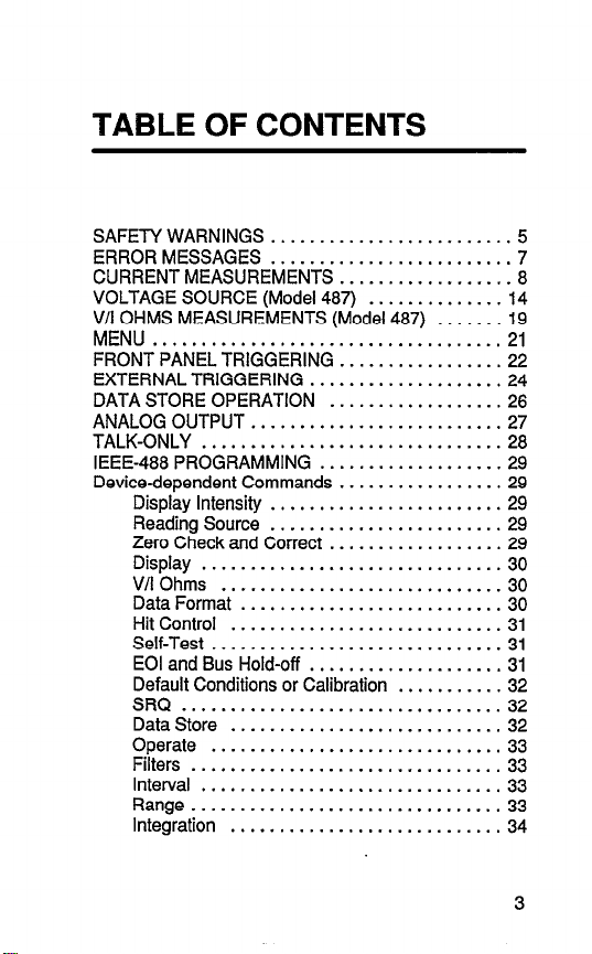
TABLE OF CONTENTS
SAFETY WARNINGS
ERROR MESSAGES ......................... 7
CURRENT MEASUREMENTS
VOLTAGE SOURCE (Model 487) .............. 14
V/l OHMS MEASUREMENTS (Model 487)
MENU .................................... 21
FRONT PANEL TRIGGERING ................. 22
EXTERNAL TRIGGERING .................... 24
DATA STORE OPERATION .................. 26
ANALOG OUTPUT .......................... 27
TALK-ONLY
IEEE-488 PROGRAMMING .................. .29
Device-dependent Commands ................. 29
Display Intensity ........................ 29
Reading Source ........................ 29
Zero Check and Correct .................. 29
Display
V/lOhms
Data Format
Hit Control ............................ 31
Self-Test
EOI and Bus Hold-off
Default Conditions or Calibration ...........
SRQ
Data Store ............................ 32
Operate
Filters ................................ 33
Interval ............................... 33
Range................................3 3
Integration
...............................
.............................
...............................
.........................
..................
...........................
...........................
..............................
...................
..............................
............................
.......
19
28
..3 0
..3 0
39
31
.31
32
..3 2
33
34
5
8
3
Page 5
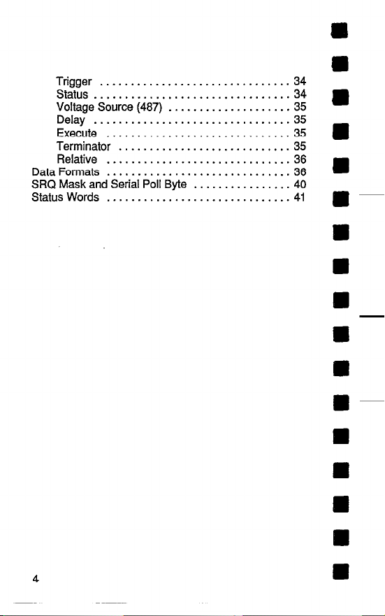
Trigger ...............................
Status.. ..............................
Voltage Source (487)
Delay ................................
Execute ............................
Terminator ..........................
Relative ..............................
Data Formats
SRQ Mask and Serial Poll Byte
StatusWords
..............................
............................
....................
................
i: l
35
..3 5
35 a
..3 5
36
36
40
..4 1
a
a
4
Page 6
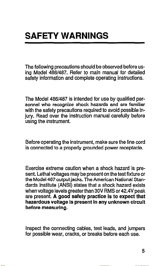
SAFETY WARNINGS
The following precautions should be observed before us-
ing Model 488/487. Refer to main manual for detailed
safety information and complete operating instructions.
The Model 48W487 is intended for use by qualified personnel who recognize shock hazards and are familiar
with the safety precautions required to avoid possible injury. Read over the instruction manual carefully before
using the instrument.
Before operating the instrument, make sure the line cord
is connected to a properly grounded power receptacle.
Exercise extreme caution when a shock hazard is pre-
sent. Lethal voltages may be present on the test fixture or
the Model 487 output jacks. The American National Stan-
dards Institute (ANSI) states that a shock hazard exists
when voltage levels greater than 30V RMS or 42.4V peak
are present. A good safety practice is to expect that
hazardous voltage is present in any unknown circuit
before measuring.
Inspect the connecting cables, test leads, and jumpers
for possible wear, cracks, or breaks before each use.
5
Page 7
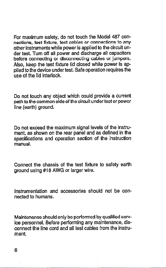
For maximum safety, do not touch the Model 487 connections, test fixture, test cables or connections to any
other instruments while power is applied to the circuit under test. Turn off all power and discharge all capacitors
before connecting or disconnecting cables or jumpers.
Also, keep the test fixture lid closed while power is applied to the device under test. Safe operation requires the
use of the lid interlock.
Do not touch any object which could provide a current
path to the common side of the circuit under test or power
line (earth) ground.
Do not exceed the maximum signal levels of the instrument, as shown on the rear panel and as defined in the
specifications and operation section of the instruction
manual.
Connect the chassis of the test fixture to safety earth
ground using #I 8 AWG or larger wire.
Instrumentation and accessories should not be con-
nected to humans.
Maintenance should only be performed by qualified service personnel. Before performing any maintenance, disconnect the line cord and all test cables from the instrument.
6
Page 8
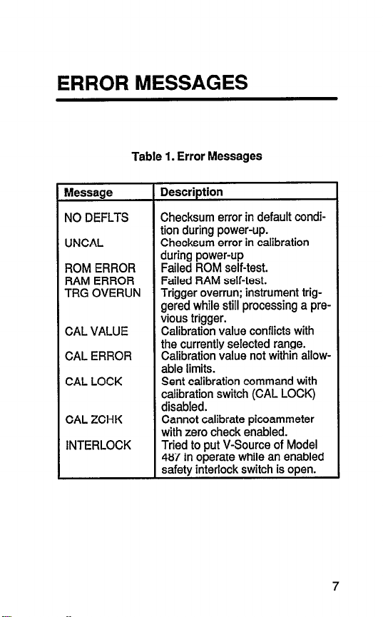
ERROR MESSAGES
Table 1. Error Messages
Message
NO DEFLTS
UNCAL
ROM ERROR
RAM ERROR
TRG OVERUN
CAL VALUE
CAL ERROR
CAL LOCK
CAL ZCHK
INTERLOCK
Description
Checksum error in default condition during power-up.
Checksum error in calibration
during power-up
Failed ROM self-test.
Failed RAM self-test.
Trigger overrun; instrument triggered while still processing a previous trigger.
Calibration value conflicts with
the currently selected range.
Calibration value not within allowable limits.
Sent calibration command with
calibration switch (CAL LOCK)
disabled.
Cannot calibrate picoammeter
with zero check enabled.
Tried to put V-Source of Model
487 in operate while an enabled
safety interlock switch is open.
Page 9
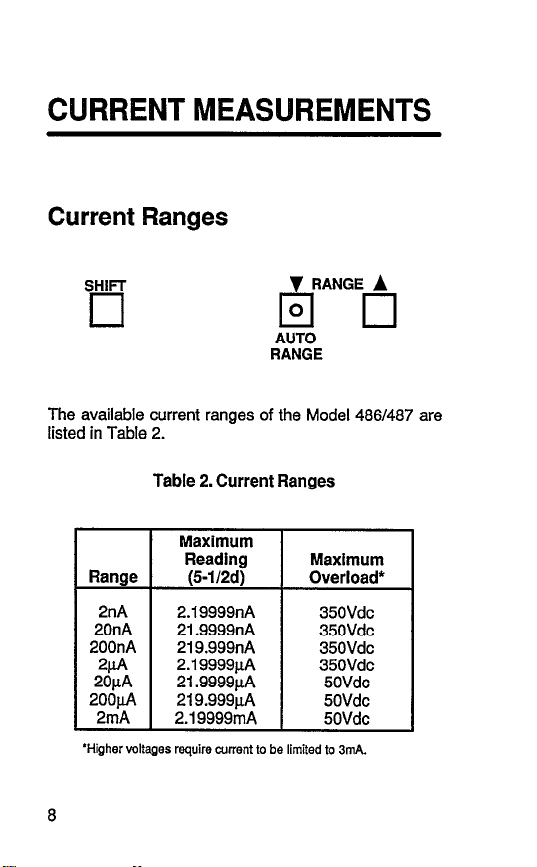
CURRENT MEASUREMENTS
Current Ranges
SHIFT
q
The available current ranges of the Model 4861487 are
listed in Table 2.
Table 2. Current Ranges
v RANGE A
El 0
AUTO
RANGE
.
2nA
20nA
200nA
2c1A
20/.iA
2oopA
2mA
‘Higher voltages require current to be limited to 3mA.
2.19999nA
21.9999nA
219.999nA
2.19999pA
21.9999pA
219.999uA
2.19999inA
35OVdc
35OVdc
35OVdc
35OVdc
5OVdc
50Vdc
50Vdc
Page 10
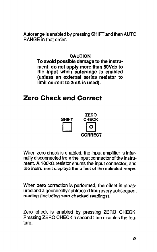
Autorange is enabled by pressing SHIFTand then AUTO
RANGE in that order.
To avoid possible damage to the instrument, do not apply more than 5OVdc to
the input when autorange is enabled
(unless an external series resistor to
limit current to 3mA is used).
CAUTION
Zero Check and Correct
ZERO
SHIFT
CHECK
q El
CORRECT
When zero check is enabled, the input amplifier is internally disconnected from the input connector of the instrument. A 1 OOkG resistor shunts the input connector, and
the instrument displays the offset of the selected range.
When zero correction is performed, the offset is measured and algebraically subtracted from every subsequent
reading (including zero checked readings).
Zero check is enabled by pressing ZERO CHECK.
Pressing ZERO CHECK a second time disables the feature.
9
Page 11
When zero correction is performed, only the present
range is zero corrected. Before making measurements, it
is recommended that each current range be zero corrected.
To perform zero correction:
1. Enable zero check.
2. To perform zero correction, press SHIFT and then
CORRECT in that order.
Filters
SHIFT
cl
Filtering is used to stabilize noisy measurements. The
Model 486/487 has two available filters; a digital filter and
an analog filter. The digital filter bases the reading on the
weighted average of a number of measurement conversions. The analog filter is a simple RC filter whose time
constant varies with the selected range.
When the filter is enabled, the selected filter(s) (digital filter, analog filter or both) will be used.
10
Page 12
To check or change the filter selection:
Press SHIFT and then FILTER SELECT in that order. One of the following messages will be displayed to indicate the currently selected filter(s):
FILTER DIGITAL
FILTER ANALOG
FILTER DIG+AN
To select a different filter, use the rotary knob or the
4 and b keys to display the desired filter selection.
Enter the displayed filter selection by pressing
SHIFT and then FILTER SELECT.
(Digital filter selected)
(Analog filter selected)
(Both digital and analog
filters selected)
Rel
REL
0
q
The rel (relative) feature serves as a means of baseline
suppression by allowing a stored offset value to be subtracted from subsequent readings. When rel is enabled,
the instrument takes the currently displayed reading as a
baseline value. All subsequent readings represent the
difference between the applied signal level and the
stored baseline.
11
Page 13
A baseline can be established for both current and VII
ohm measurements and is “remembered” by both functions.
Rel is enabled by pressing the REL key. Pressing REL a
second time disables the feature.
Making Current Measurements
To make current measurements:
1. Select a current range that is appropriate for the expected measurement or enable autorange (press
SHIFT and then AUTO RANGE).
2. Enable zero check and, if the display is not zeroed,
perform zero correction by pressing SHIFT and
then CORRECT.
3. Connect the current to be measured to the input of
the Model 486/487 (see Figures 1 and 2).
4. Disable zero check and read the measured current
on the display of the Model 486/487.
12
Page 14
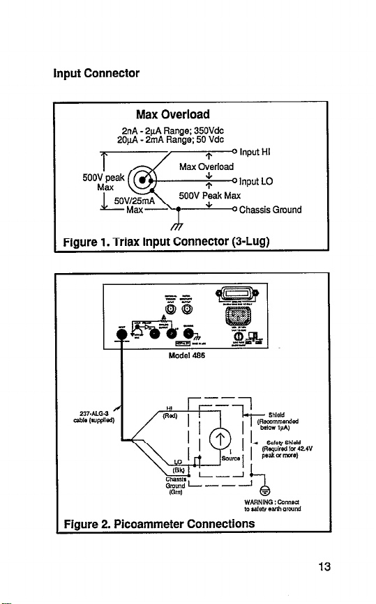
Input Connector
Max Overload
2nA - 2pA Range; 35OVdc
2OpA - 2mA Range;
50 Vdc
Chassis Gmund
Fiaure 1. Triax InDut Connector (3-Lua)
Model 486
Figure 2. Picoammeter Connections
Page 15
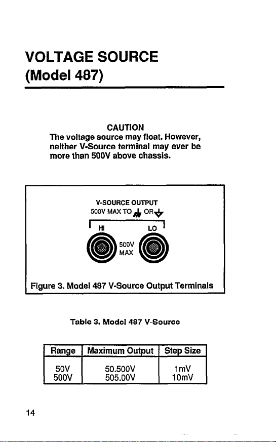
VOLTAGE SOURCE
(Model 487)
The voltage source may float. However,
CAUTION
neither V-Source terminal may ever be
more than 500V above chassis.
V-SOURCE OUTPUT
500V MAX TO ,& OR.+
I HI
LO 1
5oov
MAX
Figure 3. Model 487 V-Source Output Terminals
Table 3. Model 487 V-Source
14
Page 16

Test Fixture and Interlock
The voltage source of the Model 487 is designed to be
used with a test fixture that incorporates a safety interlock
switch, such as the Keithley Models 8002A High Resistance Test Fixture. By using the interlock feature, the
Model 487 cannot source voltage when the lid of the test
fixture is open or ajar.
Adjusting V-Source Level
The rotary knob and the4 and, keys are used to adjust
the V-Source level and select range.
With the instrument in operate (OPER-
WARNING
ATE indicator on), the displayed voltage
level (possibly hazardous) will be ap
plied to the output terminals of the VSource. The V-Source should be kept in
standby until ready to safely source
voltage to a load.
15
Page 17

Preset
PRESET
Preset allows the V-Source to be toggled between two
preset values.
To preset a V-Source level:
1.
Enable preset by pressing PRESET. Indicator wljl
turn on.
2.
Adjust the V-Source to the desired range and level.
3.
Disable preset by again pressing PRESET.
4.
Whenever preset is enabled, V-Source will adjust
to the value and range set in step 2.
I-Limit
The V-Source has current limit (l-limit) capabilities to protect the instrument and external current sensitive circuitry
from possible damage. The V-Source can be set for an
l-limit of 25pA or 2.5mA.
When l-limit occurs, the OPERATE indicator will flash.
16
Page 18

To set l-limit:
1.
Keep pressing and releasing MENU until the currently selected i-limit is displayed:
ILIMIT
or
ILIMIT
2.
Use the rotary knob to display the desired l-limit
251rA
2.5mA
value.
3.
to enter the displayed l-limit, press MENU.
Operate
5oov 2mA
MAX
OPERATE
0
III
FLASHES
IN I LIMIT
The OPERATE key toggles the output between standby
and operate. In standby, the V-Source is removed from
the rear panel output terminals. In operate, V-Source is
applied to the output terminals.
17
Page 19

V-Source Operation
While in standby, connect the V-Source as shown
1.
in Figure 4.
Use the rotary knob, and the 4 and b keys to set
2.
the desired voltage range and level.
Select the appropriate l-limit (25pA or 2.5mA).
3.
4. Press Operate.
To disable the V-Source, again press OPERATE.
5.
HI r
Model 487
3anana r;
‘lug Cables
-%---I
Figure 4. Basic V-Source Connections
18
--
Safety
7
1 Shield
Page 20

V/I OHMS MEASUREMENTS
(Model 487)
By using the V-Source in conjunction with its picoamme-
ter, the Model 487 can make resistance measurements
as high as 5.05 x 10i6fI. With V/I ohms selected, the resistance is automatically calculated from the applied voltage and measured current (R=V/I) and displayed (in
ohms) on the Model 487.
The V/I ohms function is enabled by pressing SHIFT and
then OHMS.
To make VA ohms measurements:
With zero check enabled and the V-Source in
1.
standby, connect the circuit shown in Figure 5.
Select a current range that gives the nearest full
2.
scale reading or autorange, and perform zero correction by pressing SHIFT and then CORRECT.
Set the V-Source to OV on Ihe range that will be
3.
used and press OPERATE to enable the source
output.
4.
Press REL to cancel offset current.
Set the V-Source to the desired voltage level.
5.
Disable zero check. The current measurement will
6.
be displayed.
Enable V/I ohms by pressing SHIFT and then
7.
OHMS.
To measure from a baseline resistance, enable ref
8.
while in V/I ohms.
19
Page 21

Figure 5. V/I Ohms Connections (Source V
20
Measure I)
Page 22

MENU
The menu items are listed in Table 4. In general, each
press of the MENU key displays a menu item in the order
shown in the table. The available selections of the displayed menu items are selected and displayed with the
rotary knob or the4 and, keys. The displayed option of
the displayed menu item is selected by again pressing
MENU. To exit the menu, press SHIFT and then EXIT.
Table 4. MENU items
Menu Item
DATA STORE
DATA RECL
ILIMIT
INTEGRATE
IEEE-488
DEFAULTS
SELFTEST
DEBUG
CALIBRATE
CAL V SRC
1 Description
Arm data store and set buffer size
Recall data stored in buffer
Set current limit; 25t~A or 2.5mA
(Model 487 only)
Set integration period; fast or line
cycle (50 or 60Hz)
Set IEEE-488 address O-30 or select Talk-only
Save steps as power-up defaults,
return to previously saved defaults,
or return to factory defaults
Test display and memory elements
Troubleshooting mode
Calibrate current range
Calibrate V-Source (Model 487
only)
21
Page 23

FRONT PANEL TRIGGERING
Trigger
In general,
sources) Is penormea ay:
1. Press SETUP to display the setup.
2. Use the rotary knob to display the desired option of
3. Press SHIFT and then SETUP to select the dis-
Trigger Mode
In the one-shot mode, a separate trigger is required to initiate each reading. For the multiple mode, however, only
a single trigger is required.
Setups
trigger setup (mode, internal, delay and
I .
the setup.
played setup.
. .
22
Page 24

Trigger Interval
Determines the time period between individual readings
when the instrument is in the multiple trigger mode.
The trigger interval can be set from 1Omsec to
999.999sec.
Trigger Delay
Time from the trigger point until the unit takes a reading.
In the multiple trigger mode, the delay period affects only
the first conversion; however in the one-shot trigger
mode, the delay period affects every conversion.
The Model 4861487 can be programmed for adelay interval from Osec to 999.999sec in 1 msec increments.
Trigger Sources
Available trigger source selections:
TRIG SRC EXTERNAL
TRIG SRC OPERATE
TRIG SRC BUS X
TRIG SRC GET
TRIG SRC TALK
23
Page 25

EXTERNAL TRIGGERING
EXTERNAL METER
TRIGGER COMPLETE
INPUT OUTPUT
Figure 6. Trigger Connectors
Triggers on
Figure 7. External Trigger Pulse Specifications
24
Page 26

Figure 8. Meter Complete Specifications
25
Page 27

DATA STORE OPERATION
Storing Data
1. Set the trigger mode, interval and delay.
2. Arm data store and set buffer size as follows:
A. Press MENU until the data store is selected,
and use the rotary knob to display the following:
DATA STORE YES
B. Press MENU to display buffer size.
C. Use the rotary knob or thedand, keys to dis-
play the desired buffer size value.
D. Press MENU.
3. Press TRIGGER to initiate storage.
Recalling Data
1. Press MENU until data recall is selected, and use
the rotary knob to display the following message:
DATA RECL YES
2. Press MENU. The reading stored in the first memory location will be displayed.
3. For sequential access, use the rotary knob.
4. To access a reading at a particular memory location, adjust the display to the desired location value.
5. To exit data recall, press SHIFT and then EXIT.
26
Page 28

ANALOG OUTPUT
The Model 4861487 has a non-inverting analog output.
For a 200,000 count input, the analog output will be 2V.
27
Page 29

TALK-ONLY
In talk-only, the Model 486/487 will talk continuously on
the IEEE-488 bus and output readings to a listen-only device whenever a measurement conversion occurs.
To place the Model 4861487 in talk-only:
1. Press and release MENU until the present
IEEE-488 selection is displayed.
2. Use the rotary knob to display talk-only as follows:
IEEE-488
3. Press MENU. The TALK indicator will turn on.
4. Exit the menu by pressing SHIFT and then EXIT.
28
TALK ONLY
Page 30

IEEE-488 PROGRAMMING
Device-dependent Commands
Ml
Reading Source
Readings from A/D
Single reading From data store
All readings from data store
Maximum reading from data store
Minimum reading from data store
Zero Check and Correct
Disable zero check
Enable zero check
Enable zero check and perform zero cor-
rection
29
Page 31

Display
Da
D
Display up to 18 character (a) message
Cancel display mode
V/I Ohms
Disable V/I ohms
Enable V/I ohms
1 Data Format
ASCII rdgs with prefix
ASCII rdgs without prefix
ASCII rdgs and buffer locations with prefix
ASCII rdgs and buffer locations without
prefix
G4
Binary rdgs: IEEE Std 754 single-precision, bytes reversed for Intel CPUs
G5
Binary rdgs: IEEE Std 754 single-precision, bvtes in normal order for Motorola
CPUS -
~ G8
Binary rdgs: counts and exponent, bytes
reversed for Intel CPUs
G7
Binary rdgs: counts and exponent, bytes
in normal order for Motorola CPUs
30
Page 32

Hit Control
Hit DISPLAY INTENSITY key
L-L
Hit LOCAL key
Hit SHIFT key
E
K
H7
H8
HQ
H10
Hi1
H12
H13
Hit MENU key
Hit ZERO CHECK key
Hit FILTER key
Hit RANGEI key
Hit REL key
Hit RANGEAkey
Hit SETUP key
Hit TRIGGER key
Hit OPERATE key (487)
!$FtESET key (487)
Hi4 ’
HI5
H16
Hi7
Self-Test
Hit
R Hit otary Knob counterclockwise
Hit Rotary Knob clockwise
Perform ROM/RAM self-test
Perform disalav and ROM/RAM self-test
i EOI and Bus Hold-off
1; EnableEOIandbushold-offonX 1
Disable EOI enable bus hold-off on X
Enable EOI, disable bus hold-off on X
Disable both EOI and bus hold-off on X
31
I
Page 33

Default Conditions or Calibration
LO
ki
L3,V
L4
L5
L6
SRQ
K
M2
Ii:
Ml6
M32
Ml28
Return to factory default conditions and
save (L-f)
Save present states as default conditions
Return to saved default conditions
Calibrate present measurement range
using “v”; v=-2mA to +2mA
Calibrate zero on present voltage source
range (Model 487 only)
Calibrate full scale on present voltage
source range (Model 487 only)
Prepare to calibrate present voltage
source range (Model 487 only)
Disable SRQ
Reading overflow
Data store full
Data store half full
Reading done
Ready
Error
Voltage Source Error (Model 487 only)
32
Arm data store; set buffer size ‘W’ where
Page 34

Place voltage source in operate
g
Range
Disable digital and analog filters
Enable digital filter; disable analog filter
Disable digital filter; enable analog filter
Enable digital and analog flters
Enable autorange
Select 2nA range
Select 20nA range
Select 200nA range
Select 2juI range
Select 2OpA range
Select 200pA range
Select 2mA range
No range
No range
Disable autoranoe
I
33
Page 35

I lntearation
Trigger
I
Fast integration; 1.6msec at 4-112 digit
or 2Omsec (5OHz) at 5-l/2 digit resolution
TO
T:
T3
z
G
T8
TQ
Status
34
Multiple on Talk
One-shot on Talk
Multiple on GET
One-shot on GET
Multiple on X
One-shot on X
Multiple on External Trigger
One-shot on External Trigger
Multiple on Operate (487)
One-shot on Operate (487)
Send machine status word
Send error status word
Send model number and firmware revision
Send calibration value
Send interval
Send delay
Send relative value for current
Send relative value for V/I ohms
Send voltage source value (487)
Send voltage source error status word
(487)
Page 36

I Voltaae Source 14871
I
Vn,r,l Specify voltage source level “n” in volts,
range “r” and limit “I”
n: -505 to ~505
r: 0 = 50V range; 1 = 500V range
I: 0 = 2OuA limit: 1 = 2mA limit
i Delav
Wn
Delay trigger “n”
Execute
X Execute other device-dependent com-
mands
Terminator
CR LF
?Y
LF CR
CR
E
Y4
LF
Nnnn
35
Page 37

Relative
Disable relative
E
z2,V
23
Enable relative using present reading as
baseline
Enable relative using ‘V as baseline;
v = -2mA to +2mA for current = On to
50.5PR for V/I ohms
Enable relative using the baseline previously defined
Data Formats
Finure 9. ASCII Data Format (G2: Prefix and Suffix)
36
Page 38

G5 Format (Normal order ; MotMok CPU)
Header *
A-
68yies 1 Bylei Byte2 Byle3 Byte4 a--
sign Exponent
(1 Bii (SB%s) (23 Bits)
G4 Format (Reverse mier : lnlel CPU) : Fleading bytes sem in reverse order:
‘Headers Rr IJm G4 and G5 fcxmak are shown in FQ. 4.4
** When remllinp data from the huller. one header
k l&wed by one or more readings. dependinp
on btmer sire.
Reading *’
II
l
(single preciston, IEEE-75-4)
i-leader. Byte 4. Byte 3, Byte 2. Byte 1
I
Manlksa
I
Figure 10. G4 and G5 Binary Data Formats
(IEEE Std. 754)
37
Page 39

II
I
SEytesILSBI 1 IMSB)LSB] 1
Co:nhErpdnent
(16 bitsignecij (16 bittiQnw$
I
I
MSB ---
r
6wslMSBI ( ILSBIMSBI 1 1
VExpdnarn
’ Headers for the G6. and G7 formats are shown in Fig. 4-4
‘*When recalling data from the buffer, one header
is followed by one or more readings, dependiw
on buffer&e.
NME : True k?adinQ = Counts X 10 -
Figure 11. G6 and G7 Binary Data Formats
(Counts/Exponent)
38
LSB -**
Page 40

G5 and 07 Header (6 bytes) :
Figure 12. Headers for Binary Formats
39
Page 41

1 = Data Stare Full
1 = Data Store Half Full
t- we @w
l=RQS:SRQbyMiB/487
1 = VobJe SourGw Emr
1 = FwcmQ Done
*AhwysOforkbdel4SS
n f 2
2.
EL
x
5
J
g
t
a
3
Page 42

Status Words
UO Machine Status Word
Model 466:
466 AD BO Cl GO H** JO KO MOO0 NO00
P3 Rll Sl T6 YO 20 c*
Model 467: 467 A0 BO Cl FO GO H* JO KO MOO0
NO00 00 P3 RI1 Si T6 VO1 YO ZOO c*
‘Calibratkm switch (CAL LOCK) position;
“Last pressed key
DISPLAY INTENSITY (A)
D=Normal
1 -Dim
z=off
READING SOURCE (B)
O=AfD Reading
1 -One data store reading
2=All data store reading
3=Max data store reading
4=Min data store reading
ZERO CHECK and
CORRECT (C)
O-Zero check disabled
I-Zero check enabled
VII OHMS (F)
0-W Ohms disabled
1-W Ohms enabled
DATA FORMAT(G)
O=Rdg with prefix (ASCII)
1 =Rdg without prefix (ASCII)
2=Rdg and buffer location
with prefix (ASCII)
3=Fidg and buffer location
wifhout prefix (ASCII)
4=Binary rdg - IEEE Std 754
single - $ecfslon, bytes
reversed for Intel CPUs
B-Binary Rdg - IEEE Sfd 754
singie - f?reclsion, bytes in
normal order for Motorola
CPUS
B=Binary Rdg -counts and
exponent, bytes reversed for Intel CPUs
7=Binary Rdg -Counts and
exponent, bytes in normal
order for Motorola CPUs
Figure 14. UO Machine Status Word (Factory
Defaults Shown)
41
Page 43

UO Machine Status Word (cont.)
ilT CONTROL (H)
XkPOWER’
li=DISPtAY INTENSITY’
12=LOCAL*
)3=SHIf=T
14=MENU*
XI-ZERO CHECK*
16=FILTER’
;$=;;rGEv *
&fANGE&
lo-SETUP*
1 I-TRIGGER’
12=OPERATE’
13=PRESET’
14-d’
15-b’
16=Knob rotated CCW
17=Knob rotated CW
*Last pressed
SELF-TEST (J)
O=No errors
1 -ROM error
2&AM error
3=ROM and RAM error
EOI & BUS HOLD-OFF(K)
O=EOI and Hold-off
I-No EOI and Hold-off
2=EOI and no Hold-off
3=No EOI and no Hold-off
SRQ (M)
OOO-Disabled
OOI-Reading overflow
002=Data Store Full
SRQ (M) (cant)
004=Data Store l/2 Full
008=Reading Done
01 G=Ready
032=Error
128=Voltage Source Error
DATA STORE SIZE (N)
OOO-Wrap around
nnn=OOi to 512
OPERATE (0)
O-V-Source in Standby
1 -V-Source in Operate
FILTERS (P)
O=Both Filters Disabled
1 =Digital Filter Enabled,
Analog Filter Disabled
Z=Digital Filter Disabled
Analog Filter Enabled
3=Both Filters Enabled
RANGE (RMN)
m: 0 = Autorange Disabled
1 PAutorange Enabled
n: l -2nA range
2- 20nA range
3=200nA range
4=2pA range
5=2OpA range
6=2OOuA range
7=2mA
INTEGRATION PERIOD(S)
O-Fast (4-1/2d)
1 =Line cycle (5-1i2d)
Page 44

UO Machine Status Word (cont.)
TRIGGER (-I-)
O=Multiple on Talk
1 POne-shot on Talk
2=Multiple on GET
3=One-shot on GET
4=Multiple on X
5=Oneshot on X
6=Multiple on External
Trigger
7=Cne-shot on External
Trigger
8=Multiple on Operate
S=One-shot on Operate
VOLTAGE SOURCE
(vmn)
m: 0 = 50V range
1=5OOV range
n: O-25pA Limit
1=2.5mA Limit
;Ei$llFATOR (Y)
P
1..LFCR
2&R
3=LF
4-None
RELATIVE (Zm or Zmn)
m: O-Current Rel Disabled
l-current Rel Enabled
n: 0-W Ohms Rel Disabled
1 -V/I Ohms Rel Enabled
CAL LOCK (c)
O&witch in disabled
([tied) position
a&witch in enable (locked)
position
43
Page 45

11
Cal Constants
I= E* PROM Defaults
I! P 0
G
1 I IDDCO 1 = v-source confm
l=IDDC I= v-sourcs
m
5
2
on on 011 on 011
on on on
r
r
4w487 on on on on on
s
1 ~ZeroCh6!&
1 =cs.lL!a?ked
‘I= Tf&w Overrun
1 = No Remote
$
3
2
ii
Page 46

U2 through U8 Status Words
U2 Model Number and Firmware Revision
e.g.486A03
U3 Calibration Value
e.g. CV=+O.OOOOOE-O5A
U4 Trigger Interval
8.g. TI=001.236E+OOS
U5 Trigger Delay
e.g.TD=002.000E+OOS
U6 Relative Value (Current)
e.g. RV=+1.00000E-O3A
U7 Relative Value (V/I Ohms)
8.g.RV=+l.00000E+020HM
U8 Voltage Source Value
e.g. VS=+20.000E+OOV
Figure 16. U2 through U8 Status Words
45
Page 47

U9 Voltage Source Error Status
467 O/I O/l
L
1 = Interlock Open
L
1 = Current Limited
Figure 17. U9 Voltage Source Error Status Word
46
Page 48

Keithley Instruments, Inc.
28775 Aurora Road
Cleveland, Ohio 44139
Printed in the U.S.A.
 Loading...