

Page 1

Model 4299-3
Keithley Instruments, Inc.
28775 Aurora Road
Cleveland, Ohio 44139
1-888-KEITHLEY
www.keithley.com
Universal Single Unit Rack Mount Kit
Introduction
This instruction sheet contains a parts list and installation information for the Model 4299-3 Universal Single Unit
Rack Mount Kit. This kit includes all hardware necessary to mount one half-rack instrument (either Keithley, or
Agilent unit) excluding the 260x or other products that are designated to use the rear support feature in a standard
19-inch rack.
Parts list
Table 1 lists the parts supplied with the Model 4299-3 Single Unit Universal Rack Mount Kit4299-1 parts list
4266-1 parts list
Quantity Description Keithley Part Number
1
6
1
4
6
1
4
Front Rack Ear
Cage Nut
"DO NOT DISCARD" Label
#8-32 X 3/8 LG Phillips Pan Head Screw
#10-32 X 5/8 LG Phillips Truss Head Screw
Half Rack Front Panel
M4X12 Phillips Pan Head Screw
2602-333
FA-274
MC-345
8-32X3/8PPH
10-32X5/8PHTRSH
2602-344
M4X12PPH
PA-942 Rev. A / May 2007 1
Page 2

Model 4299-3 Installation Instructions
Installation
The following procedure outlines the installation of the rack mount kit.
WARNING Make sure the instrument that is being installed is in a powered down state with all
cables unplugged. Failure to install an instrument in a discharged state may cause an
electrical shock or death.
CAUTION • Place the hottest equipment (for example, the power supply), at the top of
the rack
• Place precision equipment as low as possible in the rack (where
temperatures are cooler)
• Follow instructions included with Keithley equipment for rack mounting.
NOTE 1U is a standard vertical spacing and is equal to 1.75 inches. Typical
distance between the mounting holes on rack rails is 0.125” (1/8”).
Step 1. Prepare instrument
To prepare the instrument for mounting, remove the handle, the mounting ears, and both rear feet. The following
information outlines this process.
1. Remove the handle —The handle serves as an adjustable tilt-bail. Adjust its position by gently pulling it
away from the sides of the instrument case and swinging it up or down. To remove the handle, swing the
handle below the bottom surface of the case and back until the orientation arrows on the handles line up
with the orientation arrows on the mounting ears (refer to Figure 1). With the arrows lined up, pull the ends
of the handle away from the case.
2. Remove mounting ears.
• Remove the screw that secures each mounting ear.
• Pull down and out to remove each ear.
2 PA-942 Rev. A / May 2007
Page 3

Figure 1
Remove handle and mounting ears
Model 4299-3 Installation Instructions
Mounting ear
Handle
Mounting ear
Screw
2. Remove both rear feet from the instrument by pulling out the rubber feet and then removing the screws
underneath.
NOTE Do not re-install the feet mounting screws. Save all parts removed for future bench top
use of the instrument.
Step 2. Install mounting hardware to instrument
NOTE The instrument may be installed on the rack’s right side with the half rack
front panel on the left side as shown in the following illustrations, or on the
rack’s left side with the half rack front panel on the right side (not shown..)
1. Determine and select the unit’s side that is to be installed closest to the rack rail (see Note above).
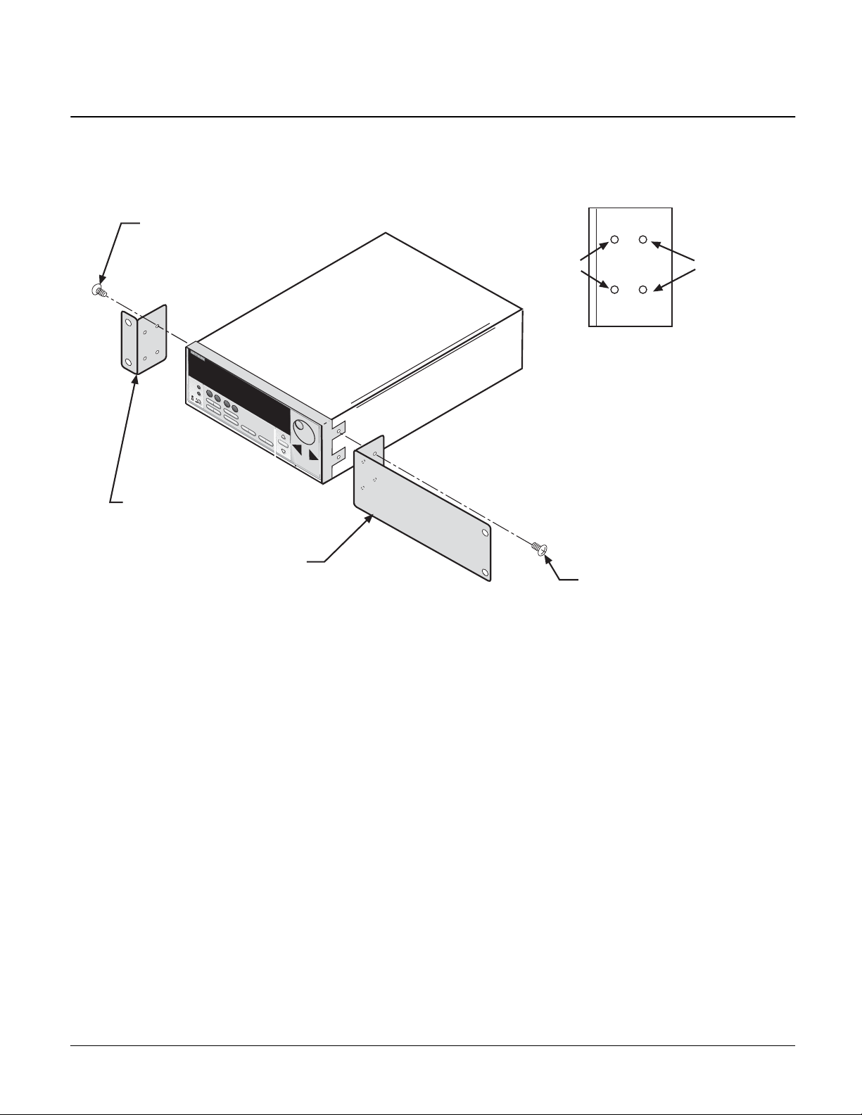
2. Secure Front Rack Ear (2602-333) using two Pan Head Screws** (refer to Figure 2).
3. Secure the Half Rack Front Panel (2602-344) to the other side of the instrument using the two remaining
Pan Head Screws**.
PA-942 Rev. A / May 2007 3
Page 4
Model 4299-3 Installation Instructions
Figure 2
Attach rack ear and dress panel to instrument
Pan Head Screw (Phillips)
8-32x3/8PPH
(2 Places)
S
H
IF
T
LO
C
A
L
P
O
W
E
R
FRONT
Front Rack Ear
(2602-333)
(See Note**)
H
O
L
D
C
O
N
F
I
G
Half Rack
Front Panel
(2602-344)
(See Note**)
Integra Series
H
A
L
T
35
0V
P
EA
K
R
A
N
G
E
A
U
T
O
R
A
N
G
E
A
M
P
S
Front
mounting
holes
Rear
mounting
holes
**When installing a 2100-DMM or Agilent unit, use
M4x12 screws in the front mounting holes; otherwise
use 8-32x3/8 screws in rear mounting holes.
Pan Head Screw (Phillips)
8-32x3/8PPH
(2 Places)
4 PA-942 Rev. A / May 2007
Page 5
Model 4299-3 Installation Instructions
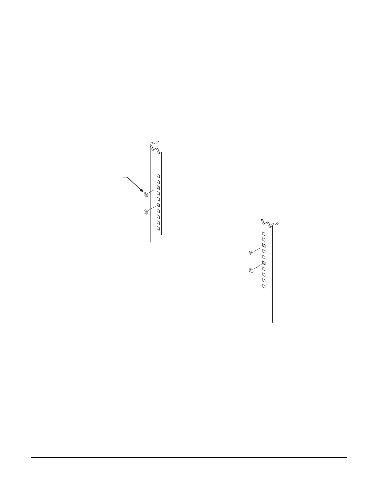
Step 3. Prepare the rack
1. Install the Cage Nuts (FA-274) into the front rack holes for the Front Rack Ear and the Half Rack Front
Panel (refer to Figure 3).
NOTE Cage nuts for the front rack ear, Half Rack Front Panel should be installed into the rails
at the same hole spacing (vertical height).
Figure 3
Cage Nut
FA-274
(4 Places)
Front Rack Rails
Step 4. Install the instrument
NOTE When rack mounting restricts access to the main power cord, provide a separate main
power disconnect device. This device must be located in close proximity to the
equipment and within easy reach of the operator.
1. While still supporting the unit, secure it to the front of the rack with four Truss Head Screws
(10-32x5/8PHTRSH).
PA-942 Rev. A / May 2007 5
Page 6

Model 4299-3 Installation Instructions
Figure 4
Instrument Installation
Rack Rails
(not included)
Truss Head Screw
(Phillips)
10-32x5/8PHTRSH
(2 Places)
S
HIFT
LOCAL
P
O
W
E
R
H
O
L
D
FRONT
C
O
Integra Series
N
F
IG
H
A
LT
3
5
0
V
P
E
A
K
R
A
N
G
E
A
U
TO
R
A
N
G
E
A
M
P
S
Truss Head Screw (Phillips)
10-32x5/8PHTRSH
(2 Places)
6 PA-942 Rev. A / May 2007
 Loading...