

Page 1

www.keithley.com
Series 2600 System SourceMeter
®
Reference Manual
2600S-901-01 Rev. C / January 2008
A GREATER MEASURE OF CONFIDENCE
Page 2

WARRANTY
Keithley Instruments, Inc. warrants this product to be free from defects in material and workmanship for a period of
one (1) year from date of shipment.
Keithley Instruments, Inc. warrants the following items for 90 days from the date of shipment: probes, cables,
software, rechargeable batteries, diskettes, and documentation.
During the warranty period, Keithley Instruments will, at its option, either repair or replace any product that proves
to be defective.
To exercise this warranty, write or call your local Keithley Instruments representative, or contact
Keithley Instruments headquarters in Cleveland, Ohio. You will be given prompt assistance and return instructions.
Send the product, transportation prepaid, to the indicated service facility. Repairs will be made and the product
returned, transportation prepaid. Repaired or replaced products are warranted for the balance of the original
warranty period, or at least 90 days.
LIMITATION OF WARRANTY
This warranty does not apply to defects resulting from product modification without Keithley Instruments’ express
written consent, or misuse of any product or part. This warranty also does not apply to fuses, software,
non-rechargeable batteries, damage from battery leakage, or problems arising from normal wear or failure to follow
instructions.
THIS WARRANTY IS IN LIEU OF ALL OTHER WARRANTIES, EXPRESSED OR IMPLIED, INCLUDING ANY
IMPLIED WARRANTY OF MERCHANTABILITY OR FITNESS FOR A PARTICULAR USE. THE REMEDIES
PROVIDED HEREIN ARE BUYER’S SOLE AND EXCLUSIVE REMEDIES.
NEITHER KEITHLEY INSTRUMENTS, INC. NOR ANY OF ITS EMPLOYEES SHALL BE LIABLE FOR ANY
DIRECT, INDIRECT, SPECIAL, INCIDENTAL, OR CONSEQUENTIAL DAMAGES ARISING OUT OF THE USE
OF ITS INSTRUMENTS AND SOFTWARE, EVEN IF KEITHLEY INSTRUMENTS, INC. HAS BEEN ADVISED IN
ADVANCE OF THE POSSIBILITY OF SUCH DAMAGES. SUCH EXCLUDED DAMAGES SHALL INCLUDE, BUT
ARE NOT LIMITED TO: COST OF REMOVAL AND INSTALLATION, LOSSES SUSTAINED AS THE RESULT OF
INJURY TO ANY PERSON, OR DAMAGE TO PROPERTY.
A G R E A T E R M E A S U R E O F C O N F I D E N C E
Keithley Instruments, Inc.
Corporate Headquarters • 28775 Aurora Road • Cleveland, Ohio 44139
440-248-0400 • Fax: 440-248-6168 • 1-888-KEITHLEY (1-888-534-8453) • www.keithley.com
3/07
Page 3

Series 2600
System SourceMeter® Instruments
Reference Manual
©2008, Keithley Instruments, Inc.
All rights reserved.
Any unauthorized reproduction, photocopy, or use the information herein, in whole or in part without the prior written
approval of Keithley Instruments, Inc. is strictly prohibited.
TSP, TSP-Link, and TSP-Net are trademarks of Keithley Instruments, Inc.
All Keithley Instruments product names are trademarks or registered trademarks of Keithley Instruments, Inc.
Other brand names are trademarks or registered trademarks of their respective holders
Cleveland, Ohio, U.S.A.
Document Number: 2600S-901-01 Rev. C / January 2008
Page 4

Manual Print History Series 2600 System SourceMeter® Instruments Reference Manual
Manual Print History
The print history shown below lists the printing dates of all Revisions and Addenda created for this
manual. The Revision Level letter increases alphabetically as the manual undergoes subsequent
updates. Addenda, which are released between Revisions, contain important change information that the
user should incorporate immediately into the manual. Addenda are numbered sequentially. When a new
Revision is created, all Addenda associated with the previous Revision of the manual are incorporated
into the new Revision of the manual. Each new Revision includes a revised copy of this print history page.
Revision A (Document Number 2600S-901-01).....................................................May 2006
Revision B (Document Number 2600S-901-01)..........................................September 2007
Revision C (Document Number 2600S-901-01) ..............................................January 2008
All Keithley Instruments product names are trademarks or registered trademarks of Keithley Instruments, Inc.
Other brand names are trademarks or registered trademarks of their respective holders.
2600S-901-01 Rev. C / January 2008
Page 5

The following safety precautions should be observed before using this product and any associated instrumentation. Although some
instruments and accessories would normally be used with non-hazardous voltages, there are situations where hazardous conditions may
be present.
This product is intended for use by qualified personnel who recognize shock hazards and are familiar with the safety precautions required
to avoid possible injury. Read and follow all installation, operation, and maintenance information carefully before using the product. Refer
to the user documentation for complete product specifications.
If the product is used in a manner not specified, the protection provided by the product warranty may be impaired.
The types of product users are:
Responsible body is the individual or group responsible for the use and maintenance of equipment, for ensuring that the equipment is
operated within its specifications and operating limits, and for ensuring that operators are adequately trained.
Operators use the product for its intended function. They must be trained in electrical safety procedures and proper use of the instrument.
They must be protected from electric shock and contact with hazardous live circuits.
Maintenance personnel perform routine procedures on the product to keep it operating properly, for example, setting the line voltage or
replacing consumable materials. Maintenance procedures are described in the user documentation. The procedures explicitly state if the
operator may perform them. Otherwise, they should be performed only by service personnel.
Safety Precautions
Service personnel are trained to work on live circuits, perform safe installations, and repair products. Only properly trained service
personnel may perform installation and service procedures.
Keithley Instruments products are designed for use with electrical signals that are rated Measurement Category I and Measurement
Category II, as described in the International Electrotechnical Commission (IEC) Standard IEC 60664. Most measurement, control, and
data I/O signals are Measurement Category I and must not be directly connected to mains voltage or to voltage sources with high transient
over-voltages. Measurement Category II connections require protection for high transient over-voltages often associated with local AC
mains connections. Assume all measurement, control, and data I/O connections are for connection to Category I sources unless otherwise
marked or described in the user documentation.
Exercise extreme caution when a shock hazard is present. Lethal voltage may be present on cable connector jacks or test fixtures. The
American National Standards Institute (ANSI) states that a shock hazard exists when voltage levels greater than 30V RMS, 42.4V peak,
or 60VDC are present. A good safety practice is to expect that hazardous voltage is present in any unknown circuit before measuring.
Operators of this product must be protected from electric shock at all times. The responsible body must ensure that operators are
prevented access and/or insulated from every connection point. In some cases, connections must be exposed to potential human contact.
Product operators in these circumstances must be trained to protect themselves from the risk of electric shock. If the circuit is capable of
operating at or above 1000V, no conductive part of the circuit may be exposed.
Do not connect switching cards directly to unlimited power circuits. They are intended to be used with impedance-limited sources. NEVER
connect switching cards directly to AC mains. When connecting sources to switching cards, install protective devices to limit fault current
and voltage to the card.
Before operating an instrument, ensure that the line cord is connected to a properly-grounded power receptacle. Inspect the connecting
cables, test leads, and jumpers for possible wear, cracks, or breaks before each use.
11/ 07
Page 6

When installing equipment where access to the main power cord is restricted, such as rack mounting, a separate main input power
disconnect device must be provided in close proximity to the equipment and within easy reach of the operator.
For maximum safety, do not touch the product, test cables, or any other instruments while power is applied to the circuit under test.
ALWAYS remove power from the entire test system and discharge any capacitors before: connecting or disconnecting cables or jumpers,
installing or removing switching cards, or making internal changes, such as installing or removing jumpers.
Do not touch any object that could provide a current path to the common side of the circuit under test or power line (earth) ground. Always
make measurements with dry hands while standing on a dry, insulated surface capable of withstanding the voltage being measured.
The instrument and accessories must be used in accordance with its specifications and operating instructions, or the safety of the
equipment may be impaired.
Do not exceed the maximum signal levels of the instruments and accessories, as defined in the specifications and operating information,
and as shown on the instrument or test fixture panels, or switching card.
When fuses are used in a product, replace with the same type and rating for continued protection against fire hazard.
Chassis connections must only be used as shield connections for measuring circuits, NOT as safety earth ground connections.
If you are using a test fixture, keep the lid closed while power is applied to the device under test. Safe operation requires the use of a lid
interlock.
If a screw is present, connect it to safety earth ground using the wire recommended in the user documentation.
The ! symbol on an instrument indicates that the user should refer to the operating instructions located in the user documentation.
The symbol on an instrument shows that it can source or measure 1000V or more, including the combined effect of normal and
common mode voltages. Use standard safety precautions to avoid personal contact with these voltages.
The symbol on an instrument shows that the surface may be hot. Avoid personal contact to prevent burns.
The symbol indicates a connection terminal to the equipment frame.
If this symbol is on a product, it indicates that mercury is present in the display lamp. Please note that the lamp must be properly
disposed of according to federal, state, and local laws.
The WARNING heading in the user documentation explains dangers that might result in personal injury or death. Always read the
associated information very carefully before performing the indicated procedure.
The CAUTION heading in the user documentation explains hazards that could damage the instrument. Such damage may invalidate the
warranty.
Instrumentation and accessories shall not be connected to humans.
Before performing any maintenance, disconnect the line cord and all test cables.
To maintain protection from electric shock and fire, replacement components in mains circuits - including the power transformer, test leads,
and input jacks - must be purchased from Keithley Instruments. Standard fuses with applicable national safety approvals may be used if
the rating and type are the same. Other components that are not safety-related may be purchased from other suppliers as long as they
are equivalent to the original component (note that selected parts should be purchased only through Keithley Instruments to maintain
accuracy and functionality of the product). If you are unsure about the applicability of a replacement component, call a Keithley Instruments
office for information.
To clean an instrument, use a damp cloth or mild, water-based cleaner. Clean the exterior of the instrument only. Do not apply cleaner
directly to the instrument or allow liquids to enter or spill on the instrument. Products that consist of a circuit board with no case or chassis
(e.g., a data acquisition board for installation into a computer) should never require cleaning if handled according to instructions. If the
board becomes contaminated and operation is affected, the board should be returned to the factory for proper cleaning/servicing.
Page 7

Table of Contents
1 Getting Started ....................................................................................... 1-1
Introduction................................................................................................. 1-2
Capabilities and features...................................................................... 1-2
Organization of manual sections.......................................................... 1-3
General information .................................................................................... 1-3
Warranty information............................................................................ 1-3
Contact information .............................................................................. 1-3
Safety symbols and terms.................................................................... 1-3
Unpacking and inspection.................................................................... 1-3
Options and accessories...................................................................... 1-4
User’s and Reference manuals............................................................ 1-5
Front and rear panel familiarization ............................................................ 1-6
Front panel summaries......................................................................... 1-6
Rear panel summaries ......................................................................... 1-9
Cooling vents............................................................................................ 1-13
Power-up .................................................................................................. 1-14
Line power connection ....................................................................... 1-14
Power-up sequence ........................................................................... 1-15
Beeper................................................................................................ 1-15
Display modes .......................................................................................... 1-16
Editing controls ......................................................................................... 1-17
Source and compliance editing .......................................................... 1-17
Menu navigation................................................................................. 1-18
Menu types......................................................................................... 1-19
Interface selection..................................................................................... 1-20
To select the GPIB interface............................................................... 1-21
To select the RS-232 interface ........................................................... 1-21
Error and status messages....................................................................... 1-21
Default settings......................................................................................... 1-21
Front panel setups.............................................................................. 1-21
Remote operation setups ................................................................... 1-22
Remote programming............................................................................... 1-24
Requesting readings .......................................................................... 1-24
Requesting command settings........................................................... 1-24
2 TSP Programming ................................................................................. 2-1
Introduction................................................................................................. 2-3
Test Script Processor (TSP)................................................................. 2-3
Run-time environment .......................................................................... 2-3
Queries................................................................................................. 2-4
Scripts .................................................................................................. 2-4
Named scripts ...................................................................................... 2-4
Functions.............................................................................................. 2-5
Scripts that create functions................................................................. 2-5
Programming overview............................................................................... 2-6
What is a chunk?.................................................................................. 2-6
What is a script?................................................................................... 2-6
Run-time environment .......................................................................... 2-7
Non-volatile memory ............................................................................ 2-7
TSP programming levels...................................................................... 2-8
Programming model for scripts ............................................................ 2-8
Installing the Test Script Builder software ................................................... 2-9
System connections.................................................................................... 2-9
Page 8

Table of Contents Series 2600 System SourceMeter® Instruments Reference Manual
GPIB ..................................................................................................... 2-9
RS-232 ............................................................................................... 2-10
Using Test Script Builder ........................................................................... 2-11
Project Navigator ................................................................................ 2-11
Script Editor ........................................................................................ 2-11
Programming Interaction .................................................................... 2-11
Starting Test Script Builder.................................................................. 2-12
Opening communications................................................................... 2-13
Creating and modifying a script .......................................................... 2-15
Script launch configuration ................................................................. 2-19
Launching a script .............................................................................. 2-22
Running a TSP file.............................................................................. 2-23
Retrieving scripts from the Series 2600.............................................. 2-23
Instrument Console ............................................................................ 2-24
File management tasks....................................................................... 2-30
Using the expanded system ...................................................................... 2-33
Sending commands and statements .................................................. 2-33
Source-measure voltage and current ................................................. 2-33
Read and write to Digital I/O port........................................................ 2-33
Display user-defined messages ......................................................... 2-34
User scripts ............................................................................................... 2-34
Script examples .................................................................................. 2-34
Creating a user script ......................................................................... 2-36
Saving a user script ............................................................................ 2-37
Running a user script.......................................................................... 2-38
Modifying a user script........................................................................ 2-40
Script management ............................................................................ 2-40
Factory scripts........................................................................................... 2-42
Running a factory script ...................................................................... 2-42
Modifying a factory script.................................................................... 2-42
Differences: Remote versus local state .............................................. 2-43
Memory considerations for the runtime environment.......................... 2-44
Test Script Language (TSL) reference ...................................................... 2-45
Introduction......................................................................................... 2-45
Reserved words.................................................................................. 2-45
Variables and types ............................................................................ 2-45
Operators............................................................................................ 2-46
Functions ............................................................................................ 2-46
Tables/arrays ...................................................................................... 2-47
Precedence ........................................................................................ 2-48
Logical operators ................................................................................ 2-48
Concatenation .................................................................................... 2-49
Branching ........................................................................................... 2-50
Loop control........................................................................................ 2-51
Standard libraries................................................................................ 2-53
3 DUT Test Connections .......................................................................... 3-1
Input/output connectors............................................................................... 3-2
Input/output LO and chassis ground ........................................................... 3-3
Sensing methods ........................................................................................ 3-5
2-wire local sensing .............................................................................. 3-6
4-wire remote sensing .......................................................................... 3-7
Sense mode selection .......................................................................... 3-8
Contact check connections ......................................................................... 3-8
Multiple SMU connections......................................................................... 3-10
Guarding and shielding ............................................................................. 3-12
Guarding............................................................................................. 3-12
Noise shield ........................................................................................ 3-13
Safety shield ....................................................................................... 3-16
Using shielding and guarding together............................................... 3-18
Test fixture................................................................................................. 3-19
Floating a SMU ......................................................................................... 3-20
Output-off states........................................................................................ 3-23
Selecting the Output-off state ............................................................. 3-23
ii 2600S-901-01 Rev. C / January 2008
Page 9

Series 2600 System SourceMeter® Instruments Reference Manual Table of Contents
4 Basic Operation...................................................................................... 4-1
Overview ..................................................................................................... 4-2
Operation overview ..................................................................................... 4-2
Source-measure capabilities ................................................................ 4-2
Compliance limit ................................................................................... 4-3
Setting the compliance limit.................................................................. 4-4
Basic circuit configurations ................................................................... 4-5
Operation considerations ............................................................................ 4-6
Warm-up ............................................................................................... 4-6
Auto zero .............................................................................................. 4-6
NPLC caching....................................................................................... 4-6
Basic source-measure procedure ............................................................... 4-8
Front panel source-measure procedure ............................................... 4-8
Remote source-measure procedure..................................................... 4-9
Measure only............................................................................................. 4-11
Sink operation ........................................................................................... 4-12
Ohms measurements ................................................................................ 4-12
Ohms calculations .............................................................................. 4-12
Ohms ranging ..................................................................................... 4-12
Basic ohms measurement procedure................................................. 4-12
Ohms sensing..................................................................................... 4-13
Sense selection .................................................................................. 4-14
Remote ohms programming ............................................................... 4-15
Power measurements ............................................................................... 4-16
Power calculations.............................................................................. 4-16
Basic power measurement procedure................................................ 4-16
Remote power programming .............................................................. 4-16
Contact check measurements................................................................... 4-17
Overview............................................................................................. 4-17
Contact check commands .................................................................. 4-18
Contact check programming example ................................................ 4-19
5 Sweep Operation.................................................................................... 5-1
Overview ..................................................................................................... 5-2
Section overview................................................................................... 5-2
Sweep overview.................................................................................... 5-2
Sweep characteristics ................................................................................. 5-3
Linear staircase sweeps ....................................................................... 5-3
Logarithmic staircase sweeps............................................................... 5-4
Pulse sweeps........................................................................................ 5-6
Custom (list) sweeps ............................................................................ 5-6
Sweep measurement storage............................................................... 5-7
Sweep functions.......................................................................................... 5-7
Staircase sweep functions .................................................................... 5-8
Pulse sweep functions.......................................................................... 5-8
Custom sweep functions....................................................................... 5-9
Running sweeps.......................................................................................... 5-9
Front panel............................................................................................ 5-9
Sweep programming examples ............................................................ 5-9
6 Range, Digits, Speed, Rel, and Filters .............................................. 6-1
Overview ..................................................................................................... 6-2
Range.......................................................................................................... 6-2
Available ranges ................................................................................... 6-2
Maximum source values and readings ................................................. 6-3
Ranging limitations ............................................................................... 6-3
Manual ranging..................................................................................... 6-3
Auto ranging ......................................................................................... 6-3
Low range limits.................................................................................... 6-3
Range considerations........................................................................... 6-4
Range programming............................................................................. 6-4
Digits ........................................................................................................... 6-6
Setting display resolution...................................................................... 6-6
Remote digits programming.................................................................. 6-6
2600S-901-01 Rev. C / January 2008 iii
Page 10

Table of Contents Series 2600 System SourceMeter® Instruments Reference Manual
Speed .......................................................................................................... 6-6
Setting speed........................................................................................ 6-7
Remote speed programming ................................................................ 6-7
Rel............................................................................................................... 6-8
Front panel rel....................................................................................... 6-8
Remote rel programming...................................................................... 6-9
Filters ........................................................................................................ 6-10
Filter types .......................................................................................... 6-10
Response time considerations ........................................................... 6-10
Front panel filter control...................................................................... 6-10
Remote filter programming ................................................................. 6-13
7 Buffer (Data Store) ................................................................................. 7-1
Overview ..................................................................................................... 7-2
Data store overview .................................................................................... 7-2
Front panel data store................................................................................. 7-2
Buffer configuration............................................................................... 7-2
Storing readings.................................................................................... 7-3
Recalling readings ................................................................................ 7-3
Remote data store....................................................................................... 7-4
Data store commands........................................................................... 7-4
Reading buffers .................................................................................... 7-5
Time and date values ........................................................................... 7-7
Buffer status.......................................................................................... 7-8
Dynamically allocated buffers............................................................... 7-8
Buffer programming examples.............................................................. 7-9
8 Source-Measure Concepts .................................................................. 8-1
Overview ..................................................................................................... 8-2
Compliance limit.......................................................................................... 8-2
Maximum compliance........................................................................... 8-2
Compliance principles .......................................................................... 8-3
Sweep waveforms....................................................................................... 8-3
Staircase sweeps.................................................................................. 8-3
Pulse sweeps........................................................................................ 8-4
Overheating protection................................................................................ 8-4
Power equations to avoid overheating ................................................. 8-4
Operating boundaries.................................................................................. 8-7
Source or sink....................................................................................... 8-7
Continuous power operating boundaries.............................................. 8-8
I-Source operating boundaries ............................................................. 8-9
V-Source operating boundaries .......................................................... 8-13
Source I measure I, source V measure V........................................... 8-16
Basic circuit configurations........................................................................ 8-16
Source I .............................................................................................. 8-16
Source V............................................................................................. 8-17
Measure only (V or I) .......................................................................... 8-17
Contact check..................................................................................... 8-18
Guard ........................................................................................................ 8-19
Guard overview .................................................................................. 8-19
Guard connections ............................................................................. 8-20
Pulse concepts.......................................................................................... 8-22
Pulse period........................................................................................ 8-22
Pulse rise and fall times...................................................................... 8-22
Pulse duty cycle.................................................................................. 8-23
Settling time considerations ...................................................................... 8-23
Measurement Settling Time Considerations....................................... 8-23
Reduction in gain-bandwidth .............................................................. 8-24
In this section: ............................................................................................. 9-1
9 System Expansion (TSP-Link) ............................................................ 9-1
Overview ..................................................................................................... 9-2
Master and Slaves................................................................................ 9-2
System configurations .......................................................................... 9-2
iv 2600S-901-01 Rev. C / January 2008
Page 11

Series 2600 System SourceMeter® Instruments Reference Manual Table of Contents
Connections ................................................................................................ 9-2
Initialization ................................................................................................. 9-3
Assigning node numbers ...................................................................... 9-3
Resetting the TSP-Link......................................................................... 9-4
Using the expanded system ........................................................................ 9-5
Accessing nodes................................................................................... 9-5
System behavior ................................................................................... 9-5
Triggering with TSP-Link ...................................................................... 9-6
TSP advanced features............................................................................... 9-6
Using groups to manage nodes on the TSP-Link network ................... 9-9
Running parallel test scripts................................................................ 9-10
Using the data queue for real-time communication............................ 9-11
Copying test scripts across the TSP-Link network ............................. 9-12
Removing stale values from the reading buffer .................................. 9-12
10 Digital I/O and Triggering ................................................................... 10-1
Overview ................................................................................................... 10-2
Digital I/O port ........................................................................................... 10-2
Port configuration................................................................................ 10-2
Digital I/O configuration ...................................................................... 10-3
Controlling digital I/O lines.................................................................. 10-4
Output Enable (Models 2601/2602) .......................................................... 10-7
Overview............................................................................................. 10-7
Operation............................................................................................ 10-7
Front panel control of Output Enable.................................................. 10-8
Remote control of Output Enable ....................................................... 10-8
Interlock (Models 2612/2612/2635/2636).................................................. 10-8
Overview............................................................................................. 10-8
Operation............................................................................................ 10-8
TSP-Link Synchronization lines .............................................................. 10-10
Connecting to TSP-Link.................................................................... 10-10
Digital I/O....................................................................................... 10-10
Remote TSP-Link synchronization line commands .......................... 10-10
Triggering ................................................................................................ 10-12
Triggering types................................................................................ 10-12
Measurement triggering.................................................................... 10-12
Front panel triggering........................................................................ 10-13
Remote triggering ............................................................................. 10-14
Hardware trigger modes.......................................................................... 10-15
Understanding synchronous triggering modes ................................. 10-20
11 Communications Interfaces .............................................................. 11 -1
Overview ................................................................................................... 11-2
Selecting an interface................................................................................ 11 -2
GPIB operation.......................................................................................... 11-2
GPIB standards .................................................................................. 11-2
GPIB connections............................................................................... 11-2
Primary address.................................................................................. 11-4
Terminator........................................................................................... 11 -5
General bus commands............................................................................ 11-6
REN (remote enable).......................................................................... 11-6
IFC (interface clear)............................................................................ 11-6
LLO (local lockout).............................................................................. 11-6
GTL (go to local) ................................................................................. 11-6
DCL (device clear).............................................................................. 11-6
SDC (selective device clear)............................................................... 11- 7
GET (group execute trigger)............................................................... 11 -7
SPE, SPD (serial polling).................................................................... 11-7
Front panel GPIB operation ...................................................................... 11-7
Error and status messages................................................................. 11 -7
GPIB status indicators ........................................................................ 11-7
LOCAL key ......................................................................................... 11-8
RS-232 interface operation ....................................................................... 11-8
2600S-901-01 Rev. C / January 2008 v
Page 12

Table of Contents Series 2600 System SourceMeter® Instruments Reference Manual
Setting RS-232 interface parameters ................................................. 11-8
Sending and receiving data................................................................ 11 -9
Terminator........................................................................................... 11 -9
Baud rate ............................................................................................ 11 -9
Data bits and parity ........................................................................... 11-10
Flow control (signal handshaking) .................................................... 11-10
RS-232 connections ......................................................................... 11-11
Error messages ................................................................................ 11-11
12 Instrument Control Library ................................................................ 12-1
Command programming notes.................................................................. 12-2
Conventions........................................................................................ 12-2
Functions and attributes ..................................................................... 12-3
TSP-Link nodes .................................................................................. 12-4
Logical instruments............................................................................. 12-5
Reading buffers .................................................................................. 12-5
Time and date values ......................................................................... 12-7
ICL functions and attributes ...................................................................... 12-8
data queue functions ........................................................................ 12-15
delay function ................................................................................... 12-17
digio functions and attributes............................................................ 12-17
display functions and attributes ........................................................ 12-23
errorqueue functions and attribute.................................................... 12-35
exit function ...................................................................................... 12-36
format attributes................................................................................ 12-36
gpib attribute..................................................................................... 12-39
localnode attribute ............................................................................ 12-39
makegetter functions ........................................................................ 12-42
printbuffer and printnumber functions............................................... 12-43
reset function.................................................................................... 12-45
serial functions and attributes........................................................... 12-45
setup functions and attribute ............................................................ 12-48
smuX functions and attributes .......................................................... 12-48
status function and attributes .................................................................. 12-76
Status register sets ........................................................................... 12-76
Status byte and SRQ ........................................................................ 12-76
timer functions....................................................................................... 12-108
trigger functions..................................................................................... 12-109
tsplink function and attributes................................................................ 12-110
userstring functions ............................................................................... 12-116
waitcomplete function............................................................................ 12-118
13 Factory Scripts ..................................................................................... 13-1
Introduction ............................................................................................... 13-2
Factory script............................................................................................. 13-2
KIGeneral ........................................................................................... 13-2
KIPulse ............................................................................................. 13-12
Advanced features for Models 2635 and 2636 ....................................... 13-13
Variable off time between pulses in a pulse train.............................. 13-13
Simultaneous IV measurement during pulse.................................... 13-13
Additional hardware triggering parameters....................................... 13-14
Flash firmware upgrade .......................................................................... 13-35
14 Display Operations .............................................................................. 14-1
Display functions and attributes ................................................................ 14-2
Display features ........................................................................................ 14-2
Display screen .................................................................................... 14-2
Measurement functions ...................................................................... 14-3
Display resolution ............................................................................... 14-3
Display messages..................................................................................... 14-4
Clearing the display ............................................................................ 14-4
Cursor position ................................................................................... 14-4
Displaying text messages................................................................... 14-5
Input prompting ......................................................................................... 14-7
vi 2600S-901-01 Rev. C / January 2008
Page 13

Series 2600 System SourceMeter® Instruments Reference Manual Table of Contents
Menu................................................................................................... 14-7
Parameter value prompting ................................................................ 14-8
Annunciators ............................................................................................. 14-9
LOCAL lockout ........................................................................................ 14-10
Load test menu ....................................................................................... 14-10
Saving a user script .......................................................................... 14-11
Adding USER TESTS menu entries ................................................. 14-11
Deleting USER TESTS menu entries ............................................... 14-12
Running a test from the front panel .................................................. 14-12
Display triggering .................................................................................... 14-12
Key-press codes ..................................................................................... 14-13
Sending keycodes ............................................................................ 14-13
Capturing key-press codes ............................................................... 14-13
15 Performance Verification.................................................................... 15-1
Introduction ............................................................................................... 15-2
Verification test requirements.................................................................... 15-2
Environmental conditions.................................................................... 15-2
Warm-up period .................................................................................. 15-2
Line power .......................................................................................... 15-3
Recommended test equipment........................................................... 15-3
Verification limits ................................................................................. 15-3
Restoring factory defaults ......................................................................... 15-4
Performing the verification test procedures............................................... 15-5
Test summary ..................................................................................... 15-5
Test considerations ............................................................................. 15-5
Setting the source range and output value......................................... 15-5
Setting the measurement range ......................................................... 15-6
Output voltage accuracy ........................................................................... 15-6
Voltage measurement accuracy................................................................ 15-8
Output current accuracy............................................................................ 15-9
Series 2600 output current accuracy 100nA and higher..................... 15-9
Model 2635/2636 output current accuracy 1nA to 100nA ranges..... 15-11
Current measurement accuracy.............................................................. 15-14
Series 2600 current measurement accuracy 100nA and higher....... 15-14
Model 2635/2636 current measurement accuracy
100pA to 100nA ranges.................................................................... 15-15
16 Calibration.............................................................................................. 16-1
Introduction ............................................................................................... 16-2
Environmental conditions.......................................................................... 16-2
Temperature and relative humidity...................................................... 16-2
Warm-up period .................................................................................. 16-2
Line power .......................................................................................... 16-2
Calibration considerations......................................................................... 16-2
Calibration cycle ................................................................................. 16-3
Recommended calibration equipment................................................ 16-3
Calibration errors ................................................................................ 16-5
Calibration ................................................................................................. 16-5
Calibration steps................................................................................. 16-5
Calibration commands........................................................................ 16-7
Calibration procedure ......................................................................... 16-8
17 Routine Maintenance .......................................................................... 17-1
Introduction ............................................................................................... 17-2
Line fuse replacement............................................................................... 17-2
Front panel tests........................................................................................ 17-3
Keys test............................................................................................. 17-3
Display Patterns test........................................................................... 17-3
2600S-901-01 Rev. C / January 2008 vii
Page 14

Table of Contents Series 2600 System SourceMeter® Instruments Reference Manual
A Specifications ........................................................................................ A-1
B Error and Status Messages ................................................................ B-1
Introduction ................................................................................................ B-2
Error summary ........................................................................................... B-2
Error effects on scripts ............................................................................... B-2
Reading errors ........................................................................................... B-2
C Common Commands ........................................................................... C-1
Common commands.................................................................................. C-2
Command summary ............................................................................ C-2
Script command equivalents................................................................ C-2
Command reference............................................................................ C-3
D Status Model........................................................................................... D-1
Overview .................................................................................................... D-2
Status byte and SRQ ........................................................................... D-2
Status register sets .............................................................................. D-2
Queues ................................................................................................ D-2
Status function summary ..................................................................... D-8
Clearing registers and queues ................................................................... D-8
Programming and reading registers........................................................... D-9
Programming enable and transition registers...................................... D-9
Reading registers .............................................................................. D-10
Status byte and service request (SRQ).................................................... D-10
Status byte register............................................................................ D-10
Service request enable register......................................................... D-12
Serial polling and SRQ ...................................................................... D-12
SPE, SPD (serial polling)................................................................... D-12
Status byte and service request commands...................................... D-12
Enable and transition registers .......................................................... D-13
Controlling node and SRQ enable registers ...................................... D-13
Status register sets................................................................................... D-15
System Summary Event Registers .................................................... D-15
Standard Event Register.................................................................... D-16
Operation Event Registers ................................................................ D-18
Measurement Event Registers .......................................................... D-24
Register programming example......................................................... D-27
Queues..................................................................................................... D-27
Output queue..................................................................................... D-27
Error queue........................................................................................ D-28
TSP-Link system status ........................................................................... D-28
Status model configuration example.................................................. D-28
E Speed Specification Test Conditions ............................................... E-1
Introduction ................................................................................................ E-2
Test system used ....................................................................................... E-2
Overview .................................................................................................... E-2
Sweep Operation Rates ...................................................................... E-2
Single Measurement Rates ................................................................. E-3
Function and Range Change Rates .................................................... E-3
Command Processing ......................................................................... E-3
Sweep Operation Rates............................................................................. E-3
Digital I/O handshaking:....................................................................... E-4
Measure to Memory............................................................................. E-4
Measure to GPIB ................................................................................. E-5
Source Measure to Memory ................................................................ E-5
Source Measure to GPIB..................................................................... E-5
Source Measure Pass/Fail to Memory................................................. E-5
Source Measure Pass/Fail to GPIB..................................................... E-5
Single Measurement Rates........................................................................ E-5
Measure to GPIB ................................................................................. E-6
Source Measure to GPIB..................................................................... E-6
viii 2600S-901-01 Rev. C / January 2008
Page 15

Series 2600 System SourceMeter® Instruments Reference Manual Table of Contents
Source Measure Pass/Fail to GPIB ..................................................... E-6
Function/ Range Change Rates................................................................. E-6
Source Range Change Rate................................................................ E-7
Measure Range Change Rate............................................................. E-7
Function Change Rate......................................................................... E-7
Command Processing................................................................................ E-7
F Display Character Codes .................................................................... F-1
Introduction ................................................................................................ F-2
Display character dot patterns............................................................. F-5
2600S-901-01 Rev. C / January 2008 ix
Page 16

Table of Contents Series 2600 System SourceMeter® Instruments Reference Manual
This page left blank intentionally.
x 2600S-901-01 Rev. C / January 2008
Page 17

List of Figures
Section Figure Title Page
1 Figure 1-1 Models 2601, 2611, 2602, 2612, 2635, and 2636 front panels...... 1-6
1 Figure 1-2 Models 2601/2611 and 2602/2612 rear panels ............................. 1-9
1 Figure 1-3 Models 2635/2636 rear panels ................................................. 1-11
1 Figure 1-4 Display modes ............................................................................. 1-16
2 Figure 2-1 Script example............................................................................... 2-7
2 Figure 2-2 Programming model for scripts...................................................... 2-9
2 Figure 2-3 GPIB cable................................................................................... 2-10
2 Figure 2-4 RS-232 cable (straight-through) .................................................. 2-10
2 Figure 2-5 Test Script Builder (example)....................................................... 2-12
2 Figure 2-6 Opening and closing communications......................................... 2-14
2 Figure 2-7 Creating and modifying a script using the Test Script Builder...... 2-15
2 Figure 2-8 Creating a project folder .............................................................. 2-16
2 Figure 2-9 Saving a script in the Test Script Builder ..................................... 2-17
2 Figure 2-10 Creating a new script file ............................................................. 2-18
2 Figure 2-11 Renaming a project folder and/or script file ................................. 2-19
2 Figure 2-12 Changing a launch configuration ................................................. 2-19
2 Figure 2-13 Opening the Run dialog box (launch configuration)..................... 2-20
2 Figure 2-14 Run dialog box (Script Attributes tab).......................................... 2-22
2 Figure 2-15 Relaunching a script from the Test Script Builder toolbar ............ 2-22
2 Figure 2-16 Re-launching a script from the Test Script Builder toolbar........... 2-23
2 Figure 2-17 Importing a script from memory of the Series 2600..................... 2-24
2 Instrument Console icons ............................................................ 2-25
2 Figure 2-18 Programming interaction tabs: Problems, Tasks and Command
Help ............................................................................................. 2-28
2 Figure 2-19 Programming interaction tabs: Language Help,
Bookmarks, Browser View........................................................... 2-29
2 Figure 2-20 Workspace Launcher and Select Workspace Directory............... 2-31
2 Figure 2-21 Importing a project from another workspace folder ..................... 2-32
2 Figure 2-22 Deleting a project......................................................................... 2-33
3 Figure 3-1 2602/2612 input/output connectors ............................................... 3-3
3 Figure 3-2 Model 2636 input/output connectors.............................................. 3-3
3 Figure 3-3 Model 2602/2612 input/output LO and chassis ground terminals.. 3-4
3 Figure 3-4 Model 2602/2612 Low-Noise Chassis Ground Banana
Jack and Chassis Screw................................................................ 3-5
3 Figure 3-5 Model 2602/2612 two-wire connections (local sensing)................ 3-6
3 Figure 3-6 Model 2602/2612 four-wire connections (remote sensing)............ 3-7
3 Figure 3-7 Contact check connections............................................................ 3-9
3 Figure 3-8 Model 2602/2612 two SMUs connected to a 3-terminal
device (local sensing) .................................................................. 3-10
3 Figure 3-9 Three SMUs connected to a 3-terminal device........................... 3-11
3 Figure 3-10 Models 2602 and 2612 high-impedance guarding....................... 3-12
3 Figure 3-11 Model 2636 high-impedance guarding (floating) ......................... 3-13
3 Figure 3-12 Model 2636 High-impedance guarding (non-floating).................. 3-13
3 Figure 3-13 Models 2602 and 2612 noise shield ............................................ 3-14
Page 18

List of Figures Series 2600 System SourceMeter® Instruments Reference Manual
3 Figure 3-14 Model 2636 noise shield (non-floating) ....................................... 3-15
3 Figure 3-15 Model 2636 noise shield (floating) .............................................. 3-15
3 Figure 3-16 Safety shield for hazardous voltage using two
2601/2602 channels (>42V)......................................................... 3-16
3 Figure 3-17 Model 2601/2602-1 connections for test circuit shown in
Figure 3-16................................................................................... 3-16
3 Figure 3-18 Safety shield for Models 2611/2612/2635/2636 hazardous voltage
(200V maximum).......................................................................... 3-17
3 Figure 3-19 Model 2601/2602-1 connections for test circuit shown in
Figure 3-18................................................................................... 3-17
3 Figure 3-20 Model 2636 connections for test circuit shown in Figure 3-18 ..... 3-18
3 Figure 3-21 Model 2601/2602-1 connections for noise shield, safety shield,
and guarding ................................................................................ 3-18
3 Figure 3-22 Model 2636 connections for noise shield, safety shield,
and guarding ................................................................................ 3-19
3 Figure 3-23 Floating the Series 2600 .............................................................. 3-21
3 Figure 3-24 Model 2601/2602-1 SMU connections for the floating
configuration shown in Figure 3-23.............................................. 3-22
4 Figure 4-1 Fundamental source measure configuration.................................. 4-5
4 Figure 4-2 2-wire resistance sensing............................................................. 4-14
4 Figure 4-3 4-wire resistance sensing............................................................. 4-14
4 Figure 4-4 Contact check measurements...................................................... 4-18
5 Figure 5-1 Comparison of staircase sweep types............................................ 5-3
5 Figure 5-2 Linear staircase sweep .................................................................. 5-4
5 Figure 5-3 Logarithmic staircase sweep (1V to 10V, five steps)...................... 5-5
5 Figure 5-4 Pulse sweep example .................................................................... 5-6
5 Figure 5-5 Custom sweep example................................................................. 5-7
6 Figure 6-1 Moving average and repeating filters........................................... 6-12
6 Figure 6-2 Media Filter .................................................................................. 6-13
8 Figure 8-1 Two basic staircase sweep waveforms .......................................... 8-3
8 Figure 8-2 Pulse sweep example .................................................................... 8-4
8 Figure 8-3 Model 2601/2602 continuous power operating boundaries ........... 8-8
8 Figure 8-4 Model 2611/2612/2635/2636 continuous power operating
boundaries ..................................................................................... 8-9
8 Figure 8-5 Model 2601/2602 I-Source boundaries........................................ 8-10
8 Figure 8-6 Model 2611/2612/2635/2636 I-Source boundaries ...................... 8-11
8 Figure 8-7 I-Source operating examples ....................................................... 8-12
8 Figure 8-8 Model 2601/2602 V-Source boundaries....................................... 8-13
8 Figure 8-9 Model 2611/2612/2635/2636 V-Source boundaries..................... 8-14
8 Figure 8-10 V-Source operating examples ...................................................... 8-15
8 Figure 8-11 Source I configuration .................................................................. 8-16
8 Figure 8-12 Source V configuration................................................................. 8-17
8 Figure 8-13 Measure only configurations ........................................................ 8-18
8 Figure 8-14 Contact check circuit configuration .............................................. 8-19
8 Figure 8-15 Comparison of unguarded and guarded measurements.............. 8-21
8 Figure 8-16 Pulse period ................................................................................. 8-22
8 Figure 8-17 Pulse rise and fall times ............................................................... 8-22
9 Figure 9-1 TSP-Link connections .................................................................... 9-3
9 Figure 9-2 Multiple TSP-Link networks............................................................ 9-7
9 Figure 9-3 Single TSP-Link network with groups ........................................... 9-8
10 Figure 10-1 Digital I/O port .............................................................................. 10-2
10 Figure 10-2 Digital I/O port configuration......................................................... 10-4
10 Figure 10-3 Using Model 2601/2602 Output Enable ....................................... 10-7
10 Figure 10-4 Using Model 2611/2612/2635/2636 Interlock............................... 10-9
10 Figure 10-5 Measurement triggering sequence............................................. 10-13
11 Figure 11-1 IEEE-488 connector ..................................................................... 11-3
xii 2600S-901-01 Rev. C / January 2008
Page 19

Series 2600 System SourceMeter® Instruments Reference Manual List of Figures
11 Figure 11-2 IEEE-488 connections.................................................................. 11-3
11 Figure 11-3 IEEE-488 and RS-232 connector locations.................................. 11 -4
11 Figure 11-4 RS-232 interface connector ....................................................... 11-10
13 Figure 13-1 Pulse sweep example ................................................................ 13-35
13 Figure 13-2 Pulse sweep example ................................................................ 13-35
14 Figure 14-1 Row/column format for display messaging .................................. 14-5
15 Figure 15-1 Connections for voltage verification ............................................. 15-7
15 Figure 15-2 Current verification connections (2602/2612(3A); 2636(1.5A)).. 15-12
15 Figure 15-3 Current verification connection ranges (2601/2602 (3A);
2611/2612/2635/2636 (1.5A))..................................................... 15-13
16 Figure 16-1 Connections for voltage calibration .............................................. 16-9
16 Figure 16-2 Connections for current calibration (100nA to 1A ranges) ......... 16-13
16 Figure 16-3 Connections for current calibration ............................................ 16-17
16 Figure 16-4 Connections for contact check 0W calibration ........................... 16-19
16 Figure 16-5 Connections for contact check 50W calibration ......................... 16-20
17 Figure 17-1 Line fuse replacement.................................................................. 17-2
D Figure D-1 Status model overview .................................................................. D-3
D Figure D-2 Status model (system summary and standard event registers) .... D-4
D Figure D-3 Status model (operation event registers) ...................................... D-5
D Figure D-4 Status model (questionable event registers)................................. D-6
D Figure D-5 Status model (measurement event registers) ............................... D-7
D Figure D-6 16-bit status register...................................................................... D-9
D Figure D-7 Status byte and service request (SRQ)....................................... D-11
D Figure D-8 Standard event register ............................................................... D-17
D Figure D-9 TSP-Link status model configuration example............................ D-30
2600S-901-01 Rev. C / January 2008 xiii
Page 20

List of Figures Series 2600 System SourceMeter® Instruments Reference Manual
This page left blank intentionally.
xiv 2600S-901-01 Rev. C / January 2008
Page 21

List of Tables
Section Table Title Page
1 Table 1-1 Connectors and triax cable conductors ....................................... 1-12
1 Table 1-2 Triax connector on ground module .............................................. 1-13
1 Table 1-3 Main Menu ................................................................................... 1-19
1 Table 1-4 Configuration menus.................................................................... 1-20
1 Table 1-5 Default settings ............................................................................ 1-23
2 Table 2-1 Example script to sweep V and measure I .................................. 2-34
2 Table 2-2 Example script using a function ................................................... 2-35
2 Table 2-3 Example interactive chunk fragment for a script.......................... 2-36
3 Table 3-1 Selecting the sense mode from the front panel ............................. 3-8
3 Table 3-2 Commands to select sense mode ................................................. 3-8
3 Table 3-3 Commands to select output-off state ........................................... 3-24
4 Table 4-1 Source-measure capabilities ......................................................... 4-3
4 Table 4-2 Maximum compliance values......................................................... 4-4
4 Table 4-3 Compliance commands ................................................................. 4-5
4 Table 4-4 Auto zero settings .......................................................................... 4-6
4 Table 4-5 Auto zero command and options ................................................... 4-7
4 Table 4-6 Basic source-measure commands .............................................. 4-10
4 Table 4-7 Basic contact check commands .................................................. 4-18
5 Table 5-1 Logarithmic sweep points .............................................................. 5-5
5 Table 5-2 Staircase sweep functions ............................................................. 5-8
5 Table 5-3 Pulse sweep functions ................................................................... 5-8
5 Table 5-4 Custom sweep functions................................................................ 5-9
5 Table 5-5 Sweep example parameters .......................................................... 5-9
6 Table 6-1 Source and measurement ranges ................................................. 6-2
6 Table 6-2 Range commands.......................................................................... 6-5
6 Table 6-3 Digits commands ........................................................................... 6-6
6 Table 6-4 Speed command............................................................................ 6-7
6 Table 6-5 Rel commands............................................................................... 6-9
6 Table 6-6 Filter commands .......................................................................... 6-13
7 Table 7-1 Data store commands.................................................................... 7-4
7 Table 7-2 Buffer storage control attributes..................................................... 7-6
7 Table 7-3 Buffer read-only attributes ............................................................. 7-6
7 Table 7-4 Buffer control programming examples........................................... 7-6
7 Table 7-5 Buffer read-only attribute programming examples......................... 7-6
7 Table 7-6 Recall attributes............................................................................. 7-7
7 Table 7-7 Buffer status bits ............................................................................ 7-8
8 Table 8-1 Maximum compliance limits........................................................... 8-2
8 Table 8-2 Model 2601/2602 Maximum Duty Cycle equation constants......... 8-6
8 Table 8-3 Model 2611/2612/2635/2636 Maximum Duty Cycle
equation constants......................................................................... 8-6
8 Table 8-4 Current Measure Settling Time1, 2.............................................. 8-23
8 Table 8-5 Current source gain-bandwidth.................................................... 8-24
9 Table 9-1 TSP-Link reset commands ............................................................ 9-4
9 Table 9-2 TSP-Link network group functions ............................................... 9-9
Page 22

List of Tables Series 2600 System SourceMeter® Instruments Reference Manual
10 Table 10-1 Digital I/O bit weighting ................................................................ 10-5
10 Table 10-2 Digital I/O commands................................................................... 10-6
10 Table 10-3 Digital I/O bit weighting .............................................................. 10-10
10 Table 10-4 TSP-Link Triggering commands................................................. 10-10
10 Table 10-5 Hardware trigger mode summary .............................................. 10-15
11 Table 11-1 General bus commands............................................................... 11-6
11 Table 11-2 RS-232 interface commands ....................................................... 11-9
11 Table 11-3 RS-232 connector pinout ........................................................... 11-10
11 Table 11-4 PC serial port pinout ................................................................... 11-11
13 Table 13-1 KIGeneral TSP test script: PulseIMeasureV................................ 13-2
13 Table 13-2 KIGeneral TSP test script: PulseVMeasureI................................ 13-3
13 Table 13-3 KIGeneral TSP test script: SweepILinMeasureV ......................... 13-4
13 Table 13-4 KIGeneral TSP test script: SweepVLinMeasureI ......................... 13-5
13 Table 13-5 KIGeneral TSP test script: SweepILogMeasureV........................ 13-7
13 Table 13-6 KIGeneral TSP test script: SweepVLogMeasureI........................ 13-8
13 Table 13-7 KIGeneral TSP test script: SweepIListMeasureV ...................... 13-10
13 Table 13-8 KIGeneral TSP test script: SweepVListMeasureI ...................... 13-11
13 Table 13-9 Required true conditions for function execution......................... 13-12
13 Table 13-10 KIGeneral TSP test script: ConfigPulseIMeasureV.................... 13-14
13 Table 13-11 KIGeneral TSP test script: ConfigPulseVMeasureI.................... 13-16
13 Table 13-12 KIGeneral TSP test script: ConfigPulseIMeasureVSweepLin .... 13-18
13 Table 13-13 KIGeneral TSP test script: ConfigPulseVMeasureISweepLin.... 13-20
13 Table 13-14 KIGeneral TSP test script: ConfigPulseIMeasureVSweepLog... 13-22
13 Table 13-15 KIGeneral TSP test script: ConfigPulseIMeasureVSweepLog... 13-24
13 Table 13-16 KIGeneral TSP test script: ConfigPulseVMeasureISweepLog... 13-26
13 Table 13-17 KIGeneral TSP test script: QueryPulseConfig ........................... 13-28
13 Table 13-18 KIGeneral TSP test script: InitiatePulseTest .............................. 13-30
13 Table 13-19 KIGeneral TSP test script: InitiatePulseTestDual....................... 13-32
14 Table 14-1 Cross referencing functions/attributes to section topics............... 14-2
14 Table 14-2 Bit identification for annunciators............................................... 14-10
14 Table 14-3 Keycodes to send for display.sendkey....................................... 14-13
14 Table 14-4 Keycode values returned for display.getlastkey ......................... 14-14
15 Table 15-1 Recommended verification equipment......................................... 15-3
15 Table 15-2 Model 2601/2602 output voltage accuracy limits ......................... 15-8
15 Table 15-3 Model 2611/2612/2635/2636 output voltage accuracy limits ....... 15-8
15 Table 15-4 Model 2601/2602 voltage measurement accuracy limits ............. 15-9
15 Table 15-5 Model 2611/2612/2635/2636 voltage measurement
accuracy limits ............................................................................. 15-9
15 Table 15-6 Model 2601/2602 output current accuracy limits ....................... 15-10
15 Table 15-7 Model 2611/2612 output current accuracy limits........................ 15-10
15 Table 15-8 Model 2635/2636 output current accuracy limits ....................... 15-14
15 Table 15-9 Model 2635/2636 Characterization of Voltage Source settings . 15-15
15 Table 15-10 Model 2601/2602 current measurement accuracy limits ........... 15-15
15 Table 15-11 Model 2611/2612 current measurement accuracy limits............ 15-16
15 Table 15-12 Model 2635/2636 current measurement accuracy limits ........... 15-16
16 Table 16-1 Recommended calibration equipment ......................................... 16-4
16 Table 16-2 Model 2601/2602 calibration steps .............................................. 16-5
16 Table 16-3 Model 2611/2612 calibration steps .............................................. 16-6
16 Table 16-4 Model 2635/2636 calibration steps .............................................. 16-6
16 Table 16-5 Calibration commands ................................................................. 16-7
16 Table 16-6 Settings of Model 2635/2636 Characterization of
Voltage Source........................................................................... 16-18
17 Table 17-1 Line fuse ...................................................................................... 17-3
B Table B-1 Error queue commands ................................................................. B-2
B Table B-2 Error summary ............................................................................... B-3
xvi 2600S-901-01 Rev. C / January 2008
Page 23

Series 2600 System SourceMeter® Instruments Reference Manual List of Tables
C Table C-1 Common commands..................................................................... C-2
C Table C-2 Script command equivalents......................................................... C-2
D Table D-1 Status functions and registers....................................................... D-8
D Table D-2 Commands to reset registers and clear queues ........................... D-9
D Table D-3 Status Byte and Service Request Enable Register commands.. D-13
D Table D-4 System node and SRQ enable register bit attributes.................. D-14
D Table D-5 Standard event commands ......................................................... D-17
D Table D-7 Operation event commands........................................................ D-18
D Table D-6 Status event status registers and bits ......................................... D-18
D Table D-8 Operation event commands........................................................ D-23
D Table D-9 Operation event commands........................................................ D-25
D Table D-10 Error queue commands .............................................................. D-28
F Table F-1 Display character codes (decimal 0-143)....................................... F-2
F Table F-2 Display character codes (decimal 144-255)................................... F-4
2600S-901-01 Rev. C / January 2008 xvii
Page 24

List of Tables Series 2600 System SourceMeter® Instruments Reference Manual
This page left blank intentionally.
xviii 2600S-901-01 Rev. C / January 2008
Page 25

In this section:
Top ic Page
Introduction ....................................................................................... 1-2
General information.......................................................................... 1-3
Front and rear panel familiarization ................................................ 1-6
Capabilities and features ..............................................................
Organization of manual sections ..................................................
Warranty information ....................................................................
Contact information.......................................................................
Safety symbols and terms ............................................................
Unpacking and inspection.............................................................
Options and accessories ..............................................................
User’s and Reference manuals
Front panel summaries.................................................................
Rear panel summaries..................................................................
Section 1
Getting Started
1-2
1-3
1-3
1-3
1-3
1-3
1-4
1-5
1-6
1-9
Cooling vents .................................................................................... 1-13
Power-up............................................................................................ 1-14
Line power connection..................................................................
Power-up sequence......................................................................
Beeper ..........................................................................................
Display modes................................................................................... 1-16
Editing controls................................................................................. 1-17
Source and compliance editing ....................................................
Menu navigation ...........................................................................
Menu types ...................................................................................
Interface selection ............................................................................ 1-20
To select the GPIB interface .........................................................
To select the RS-232 interface .....................................................
Error and status messages 1-21
Default settings ................................................................................. 1-21
Front panel setups ........................................................................
Remote operation setups..............................................................
Remote programming....................................................................... 1-24
Requesting readings.....................................................................
Requesting command settings .....................................................
1-14
1-15
1-15
1-17
1-18
1-19
1-21
1-21
1-21
1-22
1-24
1-24
Page 26

Section 1: Getting Started Series 2600 System SourceMeter® Instruments Reference Manual
Introduction
Keithley Instruments Series 2600 System SourceMeter® instruments offer electronic component
and semiconductor device manufacturers a scalable, high throughput, highly cost-effective
solution for precision DC, pulse, and low frequency AC source-measure testing.
Capabilities and features
• Models 2601/2602 System SourceMeters:
– Source ±DC voltage from 1μV to 40.4V
– Source ±DC current from 1pA to 3.03A
– Measure ±DC voltage from 1μV to 40.8V
– Measure ±DC current from 1pA to 3.06A
• Models 2611/2612 System SourceMeters:
– Source ±DC voltage from 1μV to 202V
– Source ±DC current from 1pA to 1.515A
– Measure ±DC voltage from 1μV to 204V
– Measure ±DC current from 1pA to 1.53A
• Models 2635/2636 System SourceMeters:
– Source +/- DC voltage from 1uV to 202V
– Source +/- DC current from 20fA to 1.515A
– Measure +/- DC voltage from 1uV to 204V
– Measure +/- DC current from 1fA to 1.53A
• Resistance and power measurement functions
• Contact check function
• Two independent SourceMeter channels (Models 2602, 2612, and 2636 only)
• Four-quadrant sink or source operation
• Embedded Test Script Processor (TSP) accessible from any host interface; responds to
high-speed test scripts comprised of instrument control commands
• Factory script sweep functions: Linear staircase, logarithmic staircase, fixed pulse, and
custom sweeps
• Five user-saved setups
• Buffer storage and recall for at least 100,000 source-measure readings
• Filtering to reduce reading noise
• Supported remote interfaces: IEEE-488 (GPIB) and RS-232
• TSP-Link: Allows TSP-enabled instruments to trigger and communicate with each other
• Digital I/O port: Allows the Series 2600 to control other devices
1
1. All Model 2611/2612 System SourceMeters manufactured by Keithley Instruments support the contact check function. Models 2635
and 2636 do not support the contact check function. Only Models 2601/2602 with firmware Revision 1.1.0 or later and source measure
unit (SMU) hardware Revision E or later support the contact check function. To determine the firmware and SMU hardware revisions,
inspect the data returned by the print(localnode.info()) command. The InstFwRev and SMUBrdRev keys contain the
necessary information.
1-2 Return to Section Topics 2600S-901-01 Rev. C / January 2008
Page 27

Series 2600 System SourceMeter® Instruments Reference Manual Section 1: Getting Started
Organization of manual sections
The manual sections in the PDF version of this manual can be viewed by clicking the “Bookmarks”
tab on the left side of this window. This tab also provides direct links to the various sections and
section topics.
The manual sections are also listed in the Table of Contents located at the beginning of this
manual.
General information
Warranty information
Warranty information is located at the front of this manual. Should your Series 2600 require
warranty service, contact the Keithley Instruments representative or authorized repair facility in
your area for further information. When returning the instrument for repair, be sure to complete and
return the service form at the back of this manual to provide the repair facility with the relevant
information.
Contact information
If you have any questions, please contact your local Keithley Instruments representative or call
one of our Application Engineers at 1-888-KEITHLEY (1-888-534-8453), U.S. and Canada only.
You can also contact us through our website at www.keithley.com.
Safety symbols and terms
The following symbols and terms may be found on the instrument or used in this manual:
!
The
located in the manual.
The symbol on the instrument shows that high voltage may be present on the terminal(s). Use
standard safety precautions to avoid personal contact with these voltages.
The symbol on an instrument shows that the surface may be hot. Avoid personal contact to
prevent burns.
The WARNING heading used in this manual explains dangers that might result in personal injury
or death. Always read the associated information very carefully before performing the indicated
procedure.
The CAUTION heading used in this manual explains hazards that could damage the instrument.
Such damage may invalidate the warranty.
symbol on an instrument indicates that the user should refer to the operating instructions
Unpacking and inspection
Inspection for damage
The Series 2600 was carefully inspected electrically and mechanically before shipment. After
unpacking all items from the shipping carton, check for any obvious signs of physical damage that
may have occurred during transit (there may be a protective film over the display lens, which can
be removed). Report any damage to the shipping agent immediately. Save the original packing
carton for possible future shipment. Before removing the Series 2600 from the bag, observe the
following handling precautions.
2600S-901-01 Rev. C / January 2008 Return to Section Topics 1-3
Page 28

Section 1: Getting Started Series 2600 System SourceMeter® Instruments Reference Manual
Handling precautions
• Always grasp the Series 2600 by the covers or by the handle.
• After removing the Series 2600 from its anti-static bag, inspect it for any obvious signs of
physical damage. Report any such damage to the shipping agent immediately.
• When the Series 2600 is not installed and connected, keep the unit in its anti-static bag and
store it in the original packing carton.
Package content
The following items are included with every Series 2600 order:
• Model 2601, 2602, 2611, 2612, 2635, or 2636 SourceMeter with line cord
• TSP-Link cable for Models 2601, 2602, 2611, and 2612
• Accessories as ordered
• Certificate of calibration
• CD-ROMs that contain:
• PDFs of the User’s and Reference Manuals
• Test Script Builder script development software
The following additional items are included with the Models 2611, 2612, 2635, and 2636
SourceMeters:
• Model 2600-IAC Interlock connector adaptor
The following item is for Models 2601, 2602, 2611, and 2612 only:
• Device under test (DUT) interface connector kit for each SourceMeter channel; kit includes
one hooded screw terminal connector that mates with the SourceMeter measurement
terminals
The following items are for Models 2635 and 2636 only:
• SC-73-0 6" ground wire.
• TSP-Link cable
• 2600-ALG-2 low noise triax cable with alligator clips, UL approved for up to 42V, 2m (6.6ft)
(2 with Model 2636 and 1 with Model 2635)
• Quick start guide
Options and accessories
GPIB cables, interfaces, and adaptors (connects Series 2600 to the GPIB bus)
Models 7006-1 and 7006-2: Single-shielded GPIB cables. Terminated with one straight
connector (non-stacking) and one feed-through connector. Model 7006-1 is 1m long; Model
7006-2 is 2m long.
KPCI-488LP IEEE-488: Interface/Controller for the PCI Bus.
KPXI-488 IEEE-488: Interface Board for the PXI Bus.
1-4 Return to Section Topics 2600S-901-01 Rev. C / January 2008
Page 29

Series 2600 System SourceMeter® Instruments Reference Manual Section 1: Getting Started
Models 7007-05, 7007-1, 7007-2, and 7007-4: Double-shielded premium GPIB cables. Each
end is terminated with a feed-through metal housing for longest life and best performance.
Model 7007-05 is 0.5m long; 7007-1 is 1m long; Model 7007-2 is 2m long; Model 7007-4 is 4m
long.
Model 7010: Shielded IEEE-to-IEEE adapter. Provides additional clearance between the rear
panel and GPIB cable connector. Allows easier access to cables and other connectors.
KUSB-488A IEEE-488: USB-to-GPIB Interface Adaptor
RS-232 cable (connects Series 2600 to the RS-232)
Model 7009-5 shielded RS-232 cable: This straight-through cable connects the RS-232 of
the Series 2600 to the RS-232 interface of your PC. This cable is 5ft. long and uses shielded
cable and connectors to reduce electromagnetic interference (EMI).
TSP-Link cable (connects Series 2600 to the TSP-Link)
CA-180-3A CAT 5 cable: This crossover CAT5 LAN cable connects the
TSP-Link of the Series 2600 to the TSP-Link of other instruments.
Digital I/O port cables (connects Digital I/O to other devices)
Series 2600-TLINK trigger cable: Connects the Digital I/O port of Series 2600 instruments to
other Keithley instruments equipped with Trigger Link (TLINK).
CA-126-1 DB-25 cable: DB-25 male to female DB-25 cable, 1.5m (5ft) long, used to connect
the Digital I/O port to other instruments.
User’s and Reference manuals
The User’s and Reference Manuals are provided on the product information CD-ROM in PDF
format. The User’s Manual provides the fundamental operating information for the instrument. The
Reference Manual provides additional information on the topics covered in the User’s Manual. The
Reference Manual also includes advanced operation topics and maintenance information.
2600S-901-01 Rev. C / January 2008 Return to Section Topics 1-5
Page 30
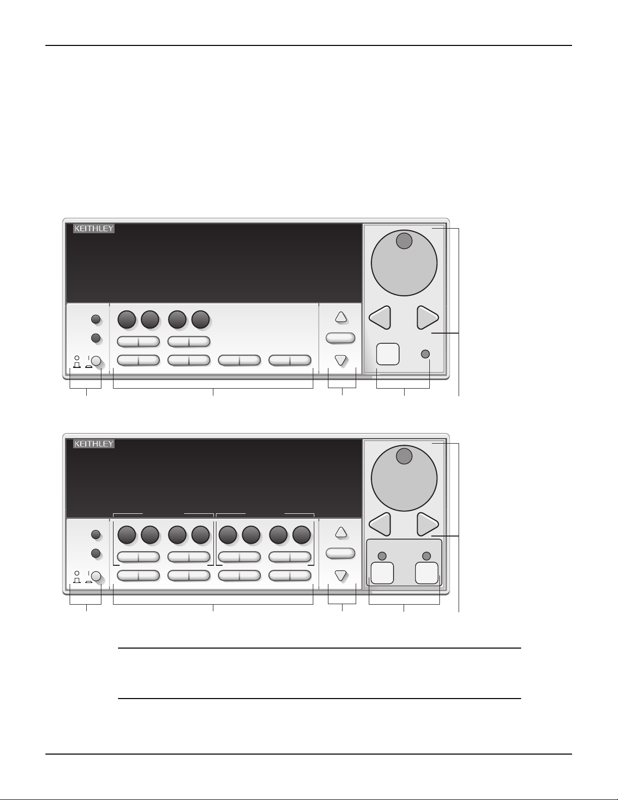
Section 1: Getting Started Series 2600 System SourceMeter® Instruments Reference Manual
Front and rear panel familiarization
Front panel summaries
The front panels of the Series 2600 are shown in Figure 1-1. The descriptions of the front panel
controls follow Figure 1-1.
Figure 1-1
Models 2601, 2611, 2602, 2612, 2635, and 2636 front panel
Models 2601, 2611, and 2635
Model 2601 and Model 2611
s
SYSTEM SourceMeter
®
KEITHLEY SourceMeter
89
7
DISPLAY
CONFIG
POWER
SRC LIMITMEAS
5
4
SPEED
DIGITS
1
2
LOAD RUN STORE RECALL
1 2
SYSTEM SourceMeter
+ / -
MODE
6
0
REL
FILTER
3
0000
TRIG MENU
Models 2602, 2612, and 2636
Model 2602 and Model 2612
®
LOCAL
EXIT ENTER
KEITHLEY SourceMeter
DISPLAY
CONFIG
POWER
CHANNEL A CHANNEL B
89
7
SRC LIMITMEAS
5
4
SPEED
DIGITS
1
2
LOAD RUN STORE RECALL
REL
+ / -
MODE
SRC LIMITMEAS
6
0
FILTER
3
0000
SPEED
DIGITS
TRIG MENU
REL
LOCAL
EXIT ENTER
MODE
FILTER
RANGE
AUTO
3
RANGE
AUT O
RANGE
P
R
P
CURSOR
U
S
H
T
O
E
D
I
T
/
E
N
T
E
R
E
T
N
E
/
T
I
D
E
O
T
H
S
U
OUTPUT
ON/OFF
4
P
R
P
CURSOR
OUTPUT
U
S
H
/
E
N
T
E
R
CHAN B
T
O
E
D
I
T
E
T
N
E
/
T
I
D
E
O
T
H
S
U
CHAN A
ON/OFF ON/OFF
5
1 2
3
4
5
NOTE The Models 2601, 2611, and 2635 have one SourceMeter channel
(Channel A), and the Models 2602, 2612, and 2636 have two
SourceMeter channels (Channel A and Channel B).
1-6 Return to Section Topics 2600S-901-01 Rev. C / January 2008
Page 31

Series 2600 System SourceMeter® Instruments Reference Manual Section 1: Getting Started
1 Special keys and power switch:
DISPLAY Toggles between the various source-measure displays and the user message mode.
Selects Model 2602/2612/2636 single or dual-channel display.
CONFIG Use to configure a function or operation.
POWER Power switch: The in position turns SourceMeter on (I); the out position turns it off (O).
Number The number keys (0-9, +/-, 0000) allow direct numeric entry in the EDIT mode.
Keys
2 Source-measure setup, performance control, and special operation:
Top row
Models 2601, 2602, 2611, 2612, 2635, and 2636:
SRC Channel A selects the source function (V or A) and places cursor in the source field for
editing.
MEAS Channel A cycles through measure functions (V, A, Ω, or W).
LIMIT Channel A places the cursor in the compliance limit field for editing.
MODE Channel A directly chooses the measurement function (V, A, Ω, or W).
Models 2602, 2612, and 2636 only:
SRC Channel B selects the source function (V or A) and places cursor in the source field.
MEAS Channel B cycles through measure functions (V, A, Ω, or W).
LIMIT Channel B places the cursor in the compliance limit field for editing.
MODE Channel B directly chooses the measurement function (V, A, Ω, or W).
Middle row
Models 2601, 2602, 2611, 2612, 2635, and 2636:
DIGITS Channel A changes display resolution to 4-1/2, 5-1/2, or 6-1/2 digits.
SPEED Channel A sets the measurement speed by controlling the A/D converter measurement
aperture.
REL Channel A controls relative, which allows a baseline value to be subtracted from a reading.
FILTER Channel A controls the digital filter, which can be used to reduce reading noise.
Models 2602, 2612, and 2636 only:
DIGITS Channel B changes display resolution to 4-1/2, 5-1/2, or 6-1/2 digits.
SPEED Channel B sets the measurement speed by controlling the A/D converter measurement
aperture.
REL Channel B controls relative, which allows a baseline value to be subtracted from a reading.
FILTER Channel B controls the digital filter, which can be used to reduce reading noise.
Bottom row
LOAD Loads factory or user-defined scripts for execution.
RUN Runs the last selected factory or user-defined scripts.
STORE Stores readings, source values, and timestamp values in one of two internal buffers
per channel for later recall.
RECALL Recalls stored readings, source values, and timestamp values from either of the two buffers.
2600S-901-01 Rev. C / January 2008 Return to Section Topics 1-7
Page 32

Section 1: Getting Started Series 2600 System SourceMeter® Instruments Reference Manual
TRIG Triggers readings.
MENU Accesses the main menu for saving and recalling setups, selecting a remote interface, line
frequency, self-tests, serial number, and beeper control.
EXIT Cancels selection and backs out of menu structure. Also used as a LOCAL key to take the
unit out of remote.
ENTER Accepts selection and moves to the next choice or exits the menu.
3 Range keys:
and Selects the next higher or lower source or measure range.
AUTO Enables or disables source or measure auto range.
4 Output control and LED status indicator:
OUTPUT ON/OFF Turns source output on or off.
LED indicator Turns on when output is on.
5 Rotary knob and CURSOR keys:
When in source edit, use the CURSOR keys for cursor control, and then rotate the knob to change a
source or compliance value. The rotary knob can also be used to enable or disable the source edit mode.
When in a menu, use the CURSOR keys or rotary knob for menu item cursor control. When displaying a
menu value, use the CURSOR keys for cursor control and rotate the knob to change the value. Pressing
the knob opens a menu item or selects a menu option or value.
6 Display annunciators (not shown):
EDIT Unit is in the source editing mode
ERR Questionable reading or invalid cal step
REM Unit in remote mode
TALK Unit is addressed to talk
LSTN Unit is addressed to listen
SRQ Service request
REL Relative mode enabled
FILT Digital filter is enabled
AUTO Auto source or measure range is selected
ARM Unit is armed and ready to run
TRIG External triggering is selected
* (asterisk) Readings are being stored in the buffer
1-8 Return to Section Topics 2600S-901-01 Rev. C / January 2008
Page 33

Series 2600 System SourceMeter® Instruments Reference Manual Section 1: Getting Started
WARNING:
NO INTERNAL OPERATOR SERVICABLE PARTS,SERVICE BY QUALIFIED PERSONNEL ONLY.
WARNING:
NO INTERNAL OPERATOR SERVICABLE PARTS,SERVICE BY QUALIFIED PERSONNEL ONLY.
CAUTION:
FOR CONTINUED PROTECTION AGAINST FIRE HAZARD,REPLACE FUSE WITH SAME TYPE AND RATING.
CAUTION:
FOR CONTINUED PROTECTION AGAINST FIRE HAZARD,REPLACE FUSE WITH SAME TYPE AND RATING.
WARNING:
NO INTERNAL OPERATOR SERVICABLE PARTS,SERVICE BY QUALIFIED PERSONNEL ONLY.
WARNING:
NO INTERNAL OPERATOR SERVICABLE PARTS,SERVICE BY QUALIFIED PERSONNEL ONLY.
CAUTION:
FOR CONTINUED PROTECTION AGAINST FIRE HAZARD,REPLACE FUSE WITH SAME TYPE AND RATING.
CAUTION:
FOR CONTINUED PROTECTION AGAINST FIRE HAZARD,REPLACE FUSE WITH SAME TYPE AND RATING.
Rear panel summaries
The rear panels of Models 2601/2611 and Models 2602/2612 are shown in Figure 1-2. The descriptions of
the rear panel components follow Figure 1-2. The rear panels of Models 2625 and 2636 are shown in
Figure 1-3. The descriptions of the rear panel components follow Figure 1-3.
Figure 1-2
Models 2601/2611 and 2602/2612 rear panel
s
2
3
2
DIGITAL I/O
IEEE-488
C
LISTED
SourceMeter
MADE IN
U.S.A.
(CHANGE IEEE ADDRESS
WITH FRONT PANEL MENU)
1
G
G
HI
G
S
HI
CAT I
CHANNEL B
DIGITAL I/O
IEEE-488
(CHANGE IEEE ADDRESS
WITH FRONT PANEL MENU)
U
4ZA4
!
Model 2601/2611
RS-232
TSP-Link
9
LO LO HIHI GGGG
R
L
US
!
45 7 8
6
Model 2602/2612
U
L
C
US
RS-232
TSP-Link
LO LO HIHI GGGG
R
LISTED
SourceMeter
S
LO
G
LO
MADE IN
U.S. A.
4ZA4
!
1
CHANNEL A
CAT I
LINE FUSE
SLOWBLOW
3.15A, 250V
!
LINE RATING
100-240VAC
50, 60Hz
240VA MAX.
SS
!
1
CHANNEL A
CAT I
LINE FUSE
SLOWBLOW
3.15A, 250V
!
LINE RATING
100-240VAC
50, 60Hz
240VA MAX.
SS
!
3
45 7 8
2600S-901-01 Rev. C / January 2008 Return to Section Topics 1-9
6
9
Page 34

Section 1: Getting Started Series 2600 System SourceMeter® Instruments Reference Manual
1 CHANNEL A and CHANNEL B (Channel B on 2602/2612 only)
Input/output connections for source, sense, and guard.
2 DIGITAL I/O
Female DB-25 connector. Fourteen pins for digital input or output, one pin for output enable (2601/2602)
or safety interlock (2611/2612); +5V and GND pins are also provided.
Use a cable equipped with a male DB-25 connector (Keithley Instruments part number CA-126-1CA).
3 IEEE-488
Connector for IEEE-488 (GPIB) operation. Use a shielded cable, such as the Model 7007-1 or Model
7007-2.
4 Cooling exhaust vent
Exhaust vent for the internal cooling fan. Keep the vent free of obstructions to prevent overheating.
5 Chassis ground
Ground screw for connections to chassis ground.
6 Low noise chassis ground
Ground jack for connecting Output HI or LO to chassis.
7 RS-232
Female DB-9 connector. For RS-232 operation, use a straight-through (not null modem) DB-9 shielded
cable (Keithley Instruments Model 7009-5) for connection to the PC.
8 TSP-Link
Expansion interface that allows a Series 2600 and other TSP-enabled instruments to
trigger and communicate with each other. Use a category 5e or higher LAN crossover cable (Keithley
Instruments part number CA-180-3A).
9 Power module
Contains the AC line receptacle and power line fuse. The instrument can operate on line voltages of 100V
to 240VAC at line frequencies of 50Hz or 60Hz.
1-10 Return to Section Topics 2600S-901-01 Rev. C / January 2008
Page 35

Series 2600 System SourceMeter® Instruments Reference Manual Section 1: Getting Started
WARNING:NO INTERNAL OPERATOR SERVICABLE PARTS,SERVICE BY QUALIFIED PERSONNEL ONLY.
WARNING:NO INTERNAL OPERATOR SERVICABLE PARTS,SERVICE BY QUALIFIED PERSONNEL ONLY.
CAUTION:FOR CONTINUED PROTECTION AGAINST FIRE HAZARD,REPLACE FUSE WITH SAME TYPE AND RATING.
CAUTION:FOR CONTINUED PROTECTION AGAINST FIRE HAZARD,REPLACE FUSE WITH SAME TYPE AND RATING.
WARNING:NO INTERNAL OPERATOR SERVICABLE PARTS,SERVICE BY QUALIFIED PERSONNEL ONLY.
WARNING:NO INTERNAL OPERATOR SERVICABLE PARTS,SERVICE BY QUALIFIED PERSONNEL ONLY.
CAUTION:FOR CONTINUED PROTECTION AGAINST FIRE HAZARD,REPLACE FUSE WITH SAME TYPE AND RATING.
CAUTION:FOR CONTINUED PROTECTION AGAINST FIRE HAZARD,REPLACE FUSE WITH SAME TYPE AND RATING.
Figure 1-3
Models 2635/2636 rear panels
2
3
MADE IN
U.S.A.
DIGITAL I/O
IEEE-488
1
4
4
Model 2635
GUARD
SENSE
HI
CHANNEL B
910
Model 2636
SENSE
HI
A LO
LO
TSP-Link
56 7
SENSE
LO
RS-232
LO
8
1
!
LINE RATING
100-240VAC
50, 60Hz
240VA MAX.
SENSE
HIHI
LO
R
CHANNEL A
LINE FUSE
SLOWBLOW
3.15A, 250V
GUARD
1
2
3
SENSE
HI
GUARD
CHANNEL B
DIGITAL I/O
IEEE-488
!
LINE RATING
100-240VAC
50, 60Hz
240VA MAX.
SENSE
HIHI
SENSE
LO
LO
SENSE
LO
HI
LO
SENSE
HI
GUARD
CHANNEL B
MADE IN
U.S.A.
5
910
SENSE
HI
A LOB LO
LO
67
RS-232
LO
TSP-Link
8
R
CHANNEL A
LINE FUSE
SLOWBLOW
3.15A, 250V
GUARD
2600S-901-01 Rev. C / January 2008 Return to Section Topics 1-11
Page 36

Section 1: Getting Started Series 2600 System SourceMeter® Instruments Reference Manual
1. CHANNEL A and CHANNEL B (Channel B on Model 2636 only)
Triax connectors for input/output, guard, and sense connections. Use only low-noise triax cables such as
the Keithley Instruments Model 7078-TRX (available in several lengths). Connector terminals and
associated triax cable conductors are as follows:
Table 1-1
Connectors and triax cable conductors
Connector Center conductor Inner ring Outer ring
LO Sense LO Input/Output LO Chassis ground
HI Input/Output HI Guard Chassis ground
SENSE HI Sense HI Guard Chassis ground
Triax cable Center conductor Inner shield Outer shield
WARNING When connecting to the model 2611, 2612, 2635 and 2636 SMU
outputs, with cables not rated for voltages above 42V, such as the
2600-ALG-2, you must disable the high voltage output by using the
INTERLOCK function as defined in section 10 of this manual.
Leaving the high voltage enabled while not properly insulating the
external connections to the unit poses a shock hazard which could
cause serious injury to the user. It is also recommended that the
LO connection terminal not be allowed to float by connecting it to
signal ground or another known signal reference.
2. DIGITAL I/O
Female DB-25 connector. Fourteen pins for digital input or output, one pin for safety interlock. Use a cable
equipped with a male DB-25 connector (Keithley Instruments part number CA-126-1CA).
3. IEEE-488
Connector for IEEE-488 (GPIB) operation. Use a shielded cable, such as the Model 7007-1 or Model
7007-2.
4. Cooling exhaust vent
Exhaust vent for internal cooling fan. Keep vent free of obstructions to prevent overheating.
5. Chassis ground
Ground screw for connections to chassis ground.
6. RS-232
Female DB-9 connector. For RS-232 operation, use a straight-through (not null modem) DB-9 shielded
cable for connection to the PC (Keithley Instruments Model 7009-5).
7. TSP-Link
Expansion interface that allows a Series 2600 and other TSP-enabled instruments to trigger and
communicate with each other. Use a category 5e or higher LAN crossover cable (Keithley Instruments
part number CA-180-3A).
8. Power module
Contains the AC line receptacle and power line fuse. The instrument can operate on line voltages of 100V
to 240VAC at line frequencies of 50Hz or 60Hz. See
instructions.
1-12 Return to Section Topics 2600S-901-01 Rev. C / January 2008
Section 17 of this manual for line fuse replacement
Page 37

Series 2600 System SourceMeter® Instruments Reference Manual Section 1: Getting Started
9. Triax connector on Ground Module
Channel A and Channel B low noise chassis ground triax connectors. Use only low-noise triax cables such
as the Keithley Model 7078-TRX. Connector terminals and associated triax cable connectors are as
follows:
Table 1-2
Triax connector on ground module
Connector Center conductor Inner ring Outer ring
LO Output Lo Floating Chassis Ground
Triax cable Center conductor Inner shield Outer shield
10. Phoenix connector on Ground Module
Channel A and Channel B Low noise chassis ground Phoenix connector.
Cooling vents
The Series 2600 has side intake and rear exhaust vents. One side must be unobstructed when
rack mounted to dissipate heat. NEVER place a container of liquid (water or coffee for instance) on
the top cover. If it spills, the liquid will enter the case through the vents and cause severe damage.
Excessive heat could damage the Series 2600 and degrade its performance. The Series 2600
must be operating in an environment where the ambient temperature does not exceed 50°C.
CAUTION To prevent damaging heat build-up and ensure specified performance,
adhere to the following precautions:
The rear exhaust vent and at least one side vent must be kept free of any
obstructions. Even partial blockage could impair proper cooling.
The rear exhaust vent and at least one side vent must be kept free of any
obstructions. Even partial blockage could impair proper cooling.
DO NOT position any devices adjacent to the Series 2600 that force air
(heated or unheated) into or onto its cooling vents or surfaces. This
additional airflow could compromise accuracy performance.
When rack mounting the Series 2600, make sure there is adequate airflow
around at least one side to ensure proper cooling. Adequate airflow enables
air temperatures within approximately one inch of the Series 2600 surfaces
to remain within specified limits under all operating conditions.
Rack mounting high power dissipation equipment adjacent to the Series
2600 could cause excessive heating to occur. The specified ambient
temperature must be maintained around the surfaces of the Series 2600 to
specified accuracies. A good measure to ensure proper cooling in rack
situations with convection cooling only is to place the hottest equipment (for
instance, the power supply) at the top of the rack. Precision equipment
(such as the Series 2600) should be placed as low as possible in the rack
where temperatures are coolest. Adding space panels below the Series
2600 will help ensure adequate air flow.
2600S-901-01 Rev. C / January 2008 Return to Section Topics 1-13
Page 38

Section 1: Getting Started Series 2600 System SourceMeter® Instruments Reference Manual
Power-up
Line power connection
Follow the procedure below to connect the Series 2600 to line power and turn on the instrument.
The SourceMeter operates from a line voltage of 100V to 240V at a frequency of 50Hz or 60Hz.
Line voltage is automatically sensed. There are no switches to set. Make sure the operating
voltage in your area is compatible.
CAUTION Operating the instrument on an incorrect line voltage may cause damage to
the instrument, possibly voiding the warranty.
1. Before plugging in the power cord, make sure that the front panel power switch is in the off
(O) position.
2. Connect the female end of the supplied power cord to the AC receptacle on the rear panel.
3. Connect the other end of the power cord to a grounded AC outlet.
WARNING The power cord supplied with the Series 2600 contains a separate
ground wire for use with grounded outlets. When proper
connections are made, the instrument chassis is connected to
power line ground through the ground wire in the power cord.
Failure to use a grounded outlet may result in personal injury or
death due to electric shock.
4. Turn the instrument on by pressing the front panel power switch to the on (I) position.
Line frequency
The Series 2600 will operate at line frequencies of either 50Hz or 60Hz. For best measurement
noise performance, the unit should be configured to match the actual line frequency used, as
follows:
1. Press the MENU > LINE-FREQ and then press ENTER.
2. Select the appropriate frequency and then press ENTER.
Note: Select AUTO to automatically detected the line frequency.
3. Press EXIT to back out of the menu structure.
Via remote, use the localnode.linefreq command to set the line frequency. For example, the
following command sets the line frequency to 60Hz:
localnode.linefreq = 60
Fuse replacement
A rear panel fuse drawer is located below the AC receptacle (refer to Figure 1-2 for Models 2601/
2602/2611/2612 and Figure 1-3 for Models 2635/2636). This fuse protects the power line input of
the instrument. If the line voltage fuse needs to be replaced, refer to "Line fuse replacement" in
Section 17.
1-14 Return to Section Topics 2600S-901-01 Rev. C / January 2008
Page 39

Series 2600 System SourceMeter® Instruments Reference Manual Section 1: Getting Started
Power-up sequence
On power-up, the Series 2600 performs self-tests on its ROM and NVRAM and momentarily lights
all segments and annunciators. If a failure is detected, the instrument momentarily displays an
error message and the ERR annunciator turns on (error messages are listed in
NOTE If a problem develops while the instrument is under warranty, return it
to Keithley Instruments, Inc., for repair.
Assuming no errors occur, the Series 2600 will power-up as follows:
• After a few seconds with the OUTPUT indicators and display pixels on, the instrument
model number, firmware revision levels, and line frequency setting are briefly displayed.
• The node and the GPIB address are displayed briefly as follows:
1. KEITHLEY MODEL 26xx
2. NODE = 1 GPIB = 26
• The node and serial port parameters are displayed briefly:
3. KEITHLEY MODEL 26xx
4. NODE = 1 SERIAL = 9600,8,N,1,NONE
• If the line frequency setting is AUTO, a screen will be displayed indicating the power line
frequency is being detected.
1
2
Appendix B).
Beeper
System identification
Serial number, firmware revision, and calibration dates can be displayed by selecting the SERIAL#
item of the main menu.
Complete the following steps to view the system information.
1. Press MENU > SYSTEM-INFO.
2. Choose one of the following:
•FIRMWARE
• SERIAL#
•CAL
For remote programming, use the *IDN? query to read system information.
With the beeper enabled, a beep will be issued to acknowledge the following actions:
• A short beep, emulating a keyclick, is issued when a front panel key is pressed.
• A short beep is also issued when the rotary knob is turned or pressed.
• A longer beep is issued when the source output is turned on.
Complete the following steps to turn the beeper on or off.
1. select MENU > BEEPER.
2. Choose one of the following:
1. Unit displays actual model number: 2601, 2602, 2611, 2612, 2635, or 2636.
2. Unit displays actual model number: 2601, 2602, 2611, 2612, 2635, or 2636.
2600S-901-01 Rev. C / January 2008 Return to Section Topics 1-15
Page 40

Section 1: Getting Started Series 2600 System SourceMeter® Instruments Reference Manual
• ENABLE
• DISABLE
Via remote, use the beeper.enable command to control the beeper. For
example, the following enables the beeper:
beeper.enable = 1
Display modes
Use the DISPLAY key to cycle through the various display modes shown in
Figure 1-4.
(Models 2602, 2612, and 2636 only) Press the Display key more than once to cycle through the
dual channel and single channel display modes. This applies to CHANNEL A (SMU A) and
CHANNEL B (SMU B).
The Models 2601, 2611, and 2635 are a single channel (SMU A). The User State display
messages are defined with specific display commands (refer to
display messaging).
Section 14 for more information on
Figure 1-4
Display modes
. V . V
SrcA:+000.000mV SrcB:+000.000mV
Press DISPLAY key
. V
SrcA:+000.000mV LimA:100.000mA
Press DISPLAY key
. V
SrcB:+000.000mV LimB:100.000mA
Press DISPLAY key
User State
Press DISPLAY key
Source-Measure display for SMU A and SMU B:
Top line displays the measure function (V, A, W or W).
Bottom line displays the source function (V or A)
and level.
Source-Measure and Compliance Limit display for SMU A:
Top line displays the measure function (V, A, W or W)
Bottom line displays the source function (V or A) and level,
and the compliance limit (A or V).
Source-Measure and Compliance Limit display for SMU B:
Top line displays the measure function (V, A, W or W)
Bottom line displays the source function (V or A) and level,
and the compliance limit (A or V).
Display for user-defined messages and prompts.
Indicates that a measured reading has not been
triggered.
1-16 Return to Section Topics 2600S-901-01 Rev. C / January 2008
Page 41

Series 2600 System SourceMeter® Instruments Reference Manual Section 1: Getting Started
Editing controls
Source and compliance editing
When the Series 2600 is in the edit mode (EDIT annunciator on), the editing controls are used to
set source and compliance values. Note that source auto ranging will turn off when editing the
source value.
Editing source values
Complete the following steps to edit the source.
1. Press the SRC key.
The cursor flashes in the source value field.
2. Use the CURSOR arrow keys to move the cursor to the desired digit using.
3. Push the Wheel in to edit the source value.
The Edit indicator displays.
4. Do one of the following to change the source value:
• Rotate the wheel to adjust the digit.
Note: The digit is automatically overflow or underflow to the next digit if the maximum
source value is reached.
• Use the numeric keys (0-9, +/-, 0000) to enter the source value.
Note: The +/- toggles the polarity, and 0000 sets the value to 0.
5. Once the desired value displays, press ENTER.
Note: The Edit indicator does not display.
6. (Optional) Press the EXIT key to cancel source editing.
Editing compliance values
Complete the following steps to edit the compliance value.
1. Do one of the following:
• (Model 2601/2611/2635 and 2602/2612/2636 in single-channel display mode only) Press
the LIMIT key.
• (Model 2602/2612/2636 dual-channel display mode only) Press LIMIT or CONFIG, then
LIMIT to edit the compliance limit.
2. Choose one of the following:
• VOLTAGE
• CURRENT
3. Use the CURSOR arrow keys to move the cursor to the desired value.
4. Press in on the wheel to enter edit mode.
The Edit indicator displays.
5. Do one of the following to modify the compliance limit value:
• Rotate the wheel to adjust the value.
Note: The value is automatically overflow or underflow to the next value if the minimum or
maximum value is reached.
• Use the numeric keys (0-9) to enter the value.
6. Press ENTER to complete editing.
Note: The Edit indicator does not display.
7. (Optional) Press the EXIT key cancel changes.
2600S-901-01 Rev. C / January 2008 Return to Section Topics 1-17
Page 42

Section 1: Getting Started Series 2600 System SourceMeter® Instruments Reference Manual
Menu navigation
When the Series 2600 is not in the edit mode (the Edit indicator does not display), the editing
controls are used to navigate the Main and Configuration menus (refer to the “menus” topic later in
Section 1) to make selections and/or set values. After entering a menu structure, use the editing
keys as follows:
Selecting menu items
1. Use the CURSOR arrow keys to select a menu or an option.
2. Press the ENTER key to select an item or menu option.
3. Rotate the wheel (clockwise or counter-clockwise) to select a value.
NOTE You can use the wheel to select items from the menu or a submenu.
4. Use the EXIT key to cancel changes or to return to the main menu.
Setting a value
There are two ways to adjust a value: Value adjust or numeric entry. Both methods use the
following editing techniques:
• To set a value to zero, press the 0000 numeric entry key.
• To toggle the polarity of a value, press the +/– numeric entry key.
Value adjust method
1. Use the CURSOR arrow keys to move the cursor to the value that you want to edited.
2. Push in on the wheel to enter edit mode.
The Edit indicator displays.
3. Rotate the wheel to set the appropriate value.
NOTE Adjusting past the maximum or minimum value automatically moves
the cursor to the next higher or lower value for editing.
4. Press ENTER to select the value. Press EXIT to cancel the change.
Numeric entry method
1. Use the CURSOR arrow keys to move the cursor to the value that you want to edit.
2. Press the number entry key (0 to 9).
The cursor moves to the next value on the right.
3. Repeat Step 2. as required to set the desired values.
4. Press ENTER to select the value.
5. (Optional) Press EXIT the cancel change and to return to the main menu.
1-18 Return to Section Topics 2600S-901-01 Rev. C / January 2008
Page 43

Series 2600 System SourceMeter® Instruments Reference Manual Section 1: Getting Started
Menu types
Many aspects of operation are configured through menus. There are two types of menus. Refer to
the
"Menu navigation" topic in this section for more details on using menus.
Main menu
The main menu is summarized in Table 1-3, along with the reference for each main selection.
To access the menu items shown in Table 1-3, press the MENU key, and then make your
selection.
NOTE Use the menu options in Table 1-3 with v1.4.0 or higher.
Table 1-3
Main menu
Menu selection Description Reference
Setup
SAVE
RECALL
POWERON
Saves and recalls user and factory setup options.
Saves user setup options.
Recalls user setup options.
Sets the default configuration.
Section 1
GPIB
ADDRESS
ENABLE
RS232
ENABLE
BAUD
BITS
PAR ITY
FLOW-CTRL
TSPLINK
NODE
RESET
DISPLAY
NUMPAD
TEST
DIGOUT
DIG-IO-OUTPUT
WRITE-PROTECT
Configure the GPIB interface options.
Configure the address for the GIPB interface.
Enables and disables the GPIB interface.
Controls the options for the RS232 interface.
Use to enable and disable the RS232 interface.
Set the baud rate.
Configure the number of bits.
Set the parity.
An alternate way to configure the instrument for
TSP-Link.
Selects the instrument node identifier.
Use to reset the TSP-link network.
Use to perform the display tests.
Enables and disables the NUMPAD.
Runs the display test.
Preforms display test patterns. Section 10
Section 11
Section 11
Section 9
Section 11
Section 9
Section 17
BEEPER
ENABLE
DISABLE
2600S-901-01 Rev. C / January 2008 Return to Section Topics 1-19
Controls the key beeps.
Enables the key beeps.
Disables key beeps.
Section 1
Page 44

Section 1: Getting Started Series 2600 System SourceMeter® Instruments Reference Manual
Menu selection Description Reference
LINE-FREQ
AUTO
50Hz
60Hz
Configure the line frequency.
Automatically selects the line frequency.
Section 1
SYSTEM-INFO
FIRMWARE
SERIAL#
CAL
Displays the system information.
Displays the version of firmware installed.
Displays the serial number of the unit.
Displays the last calibration date.
Section 1
Configuration menus
The configuration menus are summarized in Table 1-4, along with the reference for each main
selection. There are two ways to make selections:
• Press CONFIG, then navigate to the desired submenu.
• Press CONFIG, then press the associated key. For example, pressing CONFIG followed by
REL takes you directly to the Relative menu.
Table 1-4
Configuration menus
Menu selections Shortcut Description Reference
CHANNEL-A
SRC
MEAS
LIMIT
SPEED
REL
FILT
OUTPUT
CHANNEL-B
SRC
MEAS
LIMIT
SPEED
REL
FILT
OUTPUT
COMMON
TRIG
STORE
SRC
MEAS
LIMIT
SPEED
REL
FILTER
OUTPUT
SRC
MEAS
LIMIT
SPEED
REL
FILTER
OUTPUT
TRIG
STORE
Configure Channel A:
V-source sense, low range; I-source low range.
V and I-Measure sense, low range; auto zero.
V-source and I-source compliance limits.
Measurement speed (NPLC).
Set relative values.
Control digital filter.
Set off-state, control digital I/O.
Configure Channel B:
V-source sense, low range; I-source low range.
V and I-Measure sense, low range; auto zero.
V-source and I-source compliance limits.
Measurement speed (NPLC).
Set relative values.
Control digital filter.
Set off-state, control digital I/O.
Configure common functions:
Set trigger in, count, interval, and delay.
Set buffer count and destination.
Section 4
Section 4
Section 4
Section 6
Section 6
Section 6
Section 3
Section 10
Section 4
Section 4
Section 4
Section 6
Section 6
Section 6
Section 3
Section 10
Section 9
Section 7
Interface selection
The following summarizes basic interface selection for the Series 2600. Details on the interfaces,
including configuration, are provided in
described earlier in this section to select and configure the interface.
1-20 Return to Section Topics 2600S-901-01 Rev. C / January 2008
Section 11. Use the editing controls for "Menu navigation"
Page 45

Series 2600 System SourceMeter® Instruments Reference Manual Section 1: Getting Started
To select the GPIB interface
1. Press MENU > GPIB and then press ENTER.
2. Choose ADDRESS, then press ENTER.
3. Set the GPIB address (0 to 30) and press ENTER.
4. Press EXIT to return to the main menu.
To select the RS-232 interface
1. Press MENU > RS-232, then press ENTER.
2. Do the following:
• Set the BAUD rate: 300, 600, 1200, 2400, 4800, 9600,
19200, 38400, 57600, or 115200.
•Set BITS: 7 or 8.
•Set PAR ITY: NONE, ODD, or EVEN.
• Set the FLOW-CTRL: NONE or HARDWARE.
3. Press EXIT to return to the main menu.
Error and status messages
Error and status messages are displayed momentarily. During operation and programming, you
will encounter a number of front panel messages. Typical messages are either status or error
notifications, as listed in
Messages, both status and error, are held in queues. For information on retrieving error messages
from queues, refer to
Default settings
The Series 2600 can be restored to one of six setup configurations: Five user-saved setups, and
the original factory defaults. As shipped from the factory, the Series 2600 powers-up to original
default settings, which are also saved in the five user setup locations. Original default settings are
listed in
power-on setup.
Front panel setups
To save a user setup:
1. Configure the Series 2600 for the desired operating modes to be saved.
2. Press MENU > SETUP and then press ENTER.
3. Select SAVE menu item, then press ENTER.
4. Select the user number (1 through 5), and press ENTER.
Appendix B.
Appendix D.
Table 1-5. The instrument will power-up to whichever default setup was saved as the
To restore a setup:
1. Press the MENU key to access the main menu.
2. Select SETUP, then press ENTER.
3. Select the RECALL menu item, then press ENTER.
4. Do one of the following:
• Select the user number (1 through 5), and then press ENTER
2600S-901-01 Rev. C / January 2008 Return to Section Topics 1-21
Page 46

Section 1: Getting Started Series 2600 System SourceMeter® Instruments Reference Manual
•Select FACTORY to restore factory defaults, and press ENTER.
To select power-on setup:
1. Press the MENU > SETUP > POWERON, and then press ENTER
2. Do one of the following:
• Choose FACTORY to load the original defaults
•Select USER NUMBER (1 through 5) to load a user preference.
3. Press ENTER.
4. Press EXIT to return to the main menu.
Remote operation setups
To save and recall user setups:
The setup.save and setup.recall commands are used to save and recall user setups:
setup.save(n)
setup.recall(n)
This page left blank intentionally.
where:
n = 1, 2, 3, 4 or 5
Save present setup in memory.
Recall saved user setup from memory.
To restore default setups:
The reset commands return the Series 2600 to the original factory defaults:
reset() Restore all factory defaults.
smua.reset() Restore Channel A defaults.
smub.reset() Restore 2602/2612/2636 Channel B defaults.
To select power-on setup:
The setup.poweron command is used to select which setup to return to on power-up:
setup.poweron = n
where:
n = 0 (*RST defaults)
n = 1 to 5 (user setups 1-5)
Select power-on setup.
1-22 Return to Section Topics 2600S-901-01 Rev. C / January 2008
Page 47

Series 2600 System SourceMeter® Instruments Reference Manual Section 1: Getting Started
Table 1-5
Default settings
Setting Default
A/D controls:
Auto-zero Auto
Line frequency Auto (firmware version 1.2.0 or higher)
No effect (firmware versions lower than 1.2.0)
Beeper On
Data store No effect
Digital output:
Output value No effect
Write protect No effect
Digits 5-1/2
Display mode (Models 2602/2612/2636) Dual-channel
Filter: Off
Averaging type Repeat
Count 1
GPIB address No effect
Limit value:
Current limit 1A Models (2601/2602/2611/2612)
100mA Models (2635/2636)
Voltage limit 20V Models (2635/2636)
40V Models (2601/2602)
200V Models (2611/2612)
Measure:
Function Voltage
I-meter range 100mA
V-meter range 100mV Models (2601/2602)
200mV Models (2611/2612/2635/2636)
Output Off
Off state Normal
Rel Off
Current value 0.0pA
Voltage value 0mV
Ohms value 0mΩ
Watts value 0mW
RS-232 No effect
Setting Default
2600S-901-01 Rev. C / January 2008 Return to Section Topics 1-23
Page 48

Section 1: Getting Started Series 2600 System SourceMeter® Instruments Reference Manual
Table 1-5 (continued)
Default settings
Sense mode 2-wire
Source:
Function Voltage
Current value 0A
Voltage value 0V
Current range 100nA Models (2601/2602/2611/2612)
1nA Models (2635/2636)
Voltage range 100mV Models (2601/2602)
200mV Models /2611/2612/2635/2636)
Speed Normal (1 PLC)
Triggering:
Trigger-in source Immediate
Count Finite
Interval 0s
Delay 0s
TSP-Link node 1
Remote programming
Programming information is integrated with front panel operation throughout this manual. Basic
command information is listed in tables. For specific information on programming, refer to
Section 2, Section 12, and Section 13 of this manual.
Requesting readings
You can request readings by including the appropriate measurement command as the argument
for the print command. For example, the following will request a Channel A current reading:
print(smua.measure.i())
Requesting command settings
In a similar manner, settings for commands can be requested by including the command as the
argument for the print command. For example, the following command will request the voltage
source setting for Channel A:
This page left blank intentionally.
print(smua.source.levelv)
1-24 Return to Section Topics 2600S-901-01 Rev. C / January 2008
Page 49

In this section:
Top ic Page
Introduction........................................................................................ 2-3
Test Script Processor (TSP) .......................................................... 2-3
Run-time environment................................................................... 2-3
Queries.......................................................................................... 2-4
Scripts ........................................................................................... 2-4
Named scripts ............................................................................... 2-4
Functions....................................................................................... 2-5
Scripts that create functions.......................................................... 2-5
Programming overview ..................................................................... 2-6
What is a chunk?........................................................................... 2-6
What is a script?............................................................................ 2-6
Run-time environment................................................................... 2-7
Non-volatile memory ..................................................................... 2-7
TSP programming levels............................................................... 2-8
Programming model for scripts ..................................................... 2-8
Section 2
TSP Programming
Installing the Test Script Builder software ...................................... 2-9
System connections.......................................................................... 2-9
GPIB.............................................................................................. 2-9
RS-232 .......................................................................................... 2-10
Using Test Script Builder.................................................................. 2-11
Project Navigator...........................................................................
Script Editor................................................................................... 2-11
Programming Interaction............................................................... 2-11
Creating and modifying a script..................................................... 2-15
Script launch configuration............................................................ 2-19
Launching a script ......................................................................... 2-22
Running a TSP file ........................................................................
Retrieving scripts from the Series 2600 ........................................
Instrument Console ....................................................................... 2-24
File management tasks ................................................................. 2-30
2-11
2-23
2-23
Page 50

Section 2: TSP Programming Series 2600 System SourceMeter® Instruments Reference Manual
Using the expanded system............................................................. 2-33
Source-measure voltage and current ...........................................
Read and write to Digital I/O port.................................................. 2-33
Display user-defined messages .................................................. 2-34
User scripts ....................................................................................... 2-34
Script examples ............................................................................
Creating a user script ................................................................... 2-36
Saving a user script ...................................................................... 2-37
Running a user script.................................................................... 2-38
Modifying a user script.................................................................. 2-40
Script management ...................................................................... 2-40
Factory scripts .................................................................................. 2-42
Running a factory script................................................................
Modifying a factory script.............................................................. 2-42
Differences: Remote versus local state ........................................
Memory considerations for the runtime environment....................
Test Script Language (TSL) reference ............................................ 2-45
Reserved words............................................................................
Variables and types ...................................................................... 2-45
Operators...................................................................................... 2-46
Tables/arrays ................................................................................ 2-47
Functions ...................................................................................... 2-46
Precedence .................................................................................. 2-48
Logical operators .......................................................................... 2-48
Concatenation .............................................................................. 2-49
Branching ..................................................................................... 2-50
Loop control.................................................................................. 2-51
Standard libraries.......................................................................... 2-53
2-33
2-34
2-42
2-43
2-44
2-45
2-2 Return to Section Topics 2600S-901-01 Rev. C / January 2008
Page 51

Series 2600 System SourceMeter® Instruments Reference Manual Section 2: TSP Programming
Introduction
Conventional instrumentation responds to command messages sent to the instrument. Each
command message contains one or more commands. The instrument executes these commands
in order.
To conduct a test, a computer (controller) is programmed to send sequences of commands to an
instrument. The controller orchestrates the actions of the instrumentation. The controller is
typically programmed to request measurement results from the instrumentation and make test
sequence decisions based on those measurements.
Keithley Instruments’ Test Script Processor-based instruments can operate as conventional
instruments by responding to a sequence of command messages sent by a controller. They are
also capable of much more.
Test Script Processor (TSP)
Scripting To orchestrate a sequence of actions.
Scripting Language A programming language used for scripting.
The Test Script Processor (TSP) is a scripting engine that runs inside the instrument. It is capable
of running code written in a scripting language called Lua (www.lua.org). We will refer to Lua as
the Test Script Language (TSL). The TSP runs portions of TSL code formally known as chunks.
Most messages sent to the instrument are directly executed by the TSP as TSL chunks. The
simplest messages sent to the instrument would be individual instrument control commands. Even
though these messages are executed as TSL chunks, using them is no different than using a
conventional instrument. The user sends a command message and the instrument executes that
command. When sending individual command messages, it is irrelevant that the TSP is executing
the message as a chunk.
Instrument control commands are implemented as a library within the TSL. The command set for a
TSP-enabled instrument is referred to as the Instrument Control Library (ICL) for that instrument.
Each TSP-enabled instrument will have its own ICL. Although each TSP-enabled instrument runs
the same TSL, different instruments respond to different commands and the ICL for each
instrument may be different.
ICL commands are very similar to the commands sent to a conventional instrument but ICL
commands look like function calls or assignment statements. For example the command to set the
output voltage level to one volt on channel A is
to turn the Channel A output on is
when sent individually as separate messages, are each a TSL chunk.
Commands do not need to be sent as separate messages. The two commands from above can be
combined into one message, and thereby one chunk, by concatenating the two commands
together with a space separating them. The resulting chunk would be as follows:
smua.source.levelv = 1 smua.source.output = smua.OUTPUT_ON
Run-time environment
A feature of all scripting environments is the run-time environment. In the TSP, the run-time
environment is simply a collection of global variables. A global variable can be used to remember
a value as long as the unit is powered on and the variable is not assigned a new value. The
command
result in a global variable named “x.”
x = smua.measure.v() instructs the instrument to measure voltage and store the
smua.source.levelv = 1. Similarly, the command
smua.source.output = smua.OUTPUT_ON. These commands,
A global variable can be removed from the environment by assigning it the nil value. For
example, the command x = nil will remove the global variable x from the run-time environment.
2600S-901-01 Rev. C / January 2008 Return to Section Topics 2-3
Page 52

Section 2: TSP Programming Series 2600 System SourceMeter® Instruments Reference Manual
When the unit is turned off, the entire run-time environment will be lost. Note that SMU non-volatile
reading buffers are not lost.
Queries
TSP-enabled instruments do not have inherent query commands. Like any other scripting
environment the print command and other related print commands are used to generate
output. The print command will create one response message.
An example of generating an output message is the following chunk (two commands) that takes a
measurement and returns its value:
x = smua.measure.v() print(x)
Note that the measurement value is stored in the global variable x between the two commands.
Scripts
When taking advantage of the TSP to perform more complicated sequences of commands,
especially sequences utilizing advanced scripting features such as looping and branching, sending
the entire sequence in one message is very cumbersome. Two special messages can be used to
collect a sequence of command messages together into one chunk.
The loadscript message will instruct the TSP-enabled instrument to begin collecting all
subsequent messages rather than executing them immediately. After sending the sequence of
command messages, the
compile the test sequence and make it available to run in a subsequent message. This chunk is
called the “active script.”
The active script can be run at any time by sending the command script.run(). The active script
can be run many times without needing to re-send it. Each time the
given, the active script will be executed.
Sending a new script using the loadscript and endscript messages will instruct the TSPenabled instrument to replace the active script with the new script. While creating and using scripts
this way is a very powerful feature of TSP-enabled instruments, only being able to access one
script at a time in this way would be very limited. The “
named scripts to store many scripts in the instrument at one time.
Named scripts
The loadscript message can also be used to create named scripts. When the loadscript
message is used to create a named script, the active script is not replaced with the named script.
Instead, a global variable in the run-time environment is created to store the script. Because the
script is stored in a global variable, the name of the script must be a legal TSL variable name.
The name of the script is specified in the loadscript message by appending it to the name and
separating it from the
MyScript will instruct the TSP-enabled instrument to begin gathering command messages that
will be used to create a script named
endscript message is still used to indicate the end of the script. Upon receipt of the endscript
message, the instrument will compile the script. If there are no errors, the script will be made
available as the global variable
MyScript message. After a named script has been successfully sent to the instrument, it can be
run at any time by sending the
that name would be used instead.
endscript message is used to instruct the TSP-enabled instrument to
script.run() command is
Named scripts” topic describes how to use
loadscript keyword with a space character. The message loadscript
MyScript. After sending the command messages, the
MyScript because that is the name we used in the loadscript
MyScript() message. If the name given to the script were different,
If a new script is sent with the same name, it will replace the old one. Sending new scripts with
different names will not remove any previously sent scripts. By using named scripts, any number of
2-4 Return to Section Topics 2600S-901-01 Rev. C / January 2008
Page 53

Series 2600 System SourceMeter® Instruments Reference Manual Section 2: TSP Programming
scripts can be made available simultaneously within the limits of the memory available to the runtime environment.
Named scripts are stored as global variables in the run-time environment. Like all other global
variables, when the unit is powered off, they are lost. There is non-volatile storage on the instrument
that can be used to store downloaded scripts across power cycles. See “
Saving a user script” later in
this section for more information.
Functions
As previously explained, named scripts behave just like TSL functions. Executing a script is just like
executing a function with the same name as the script. Scripts, like functions, may return values.
Unlike functions, scripts may not take any parameters. In order to pass parameters to a chunk, you
must make a TSL function.
Functions are created with a message in one of the following forms:
MyFunction = function (parameter1, parameter2) function body end
or
function MyFunction(parameter1, parameter2) function body end
Where function body is a TSP chunk that will be executed when the function is called. The
above function can be executed by sending the following message:
MyFunction(value for parameter1, value for parameter2)
Where value for parameterN represents the values to be passed to the function call for the
given parameters. Note that when a function is defined, it is just another global variable in the runtime environment. Just like all global variables, functions will persist until they are removed from
the run-time environment, overwritten, or the unit is turned off.
Scripts that create functions
It is inconvenient in most cases to define a function in one message. The solution is to create a
script that defines a function. The scripts will be like any other script. It will not cause any action to
be performed on the instrument until it is executed. Remember that creating a function is just
creating a global variable that is a function. That global variable will not exist until the chunk that
creates it is executed. In this case the chunk that creates it is a script. Therefore, the function will
not exist until the script that creates it is executed. This is often confusing to first time users.
Example: Create the function MyFunction with a script named MakeMyFunction. The sequence of
messages to do this is shown as follows:
loadscript MakeMyFunction
MyFunction = function (who) --The .. operator concatenates two strings.
print("Hello " .. who)
end
endscript
After this sequence of messages is sent, the MakeMyFunction script exists on the instrument in a
global variable named
because we have not executed the
MakeMyFunction(). That message instructs the instrument to run the MakeMyFunction script
which then creates the
MakeMyFunction. The MyFunction function however does not yet exist
MakeMyFunction script. Let us now send the message
MyFunction global variable that happens to be a function.
If we now send the message MyFunction("world"), the instrument will execute the MyFunction
function, which causes the instrument to generate a response message with the text “Hello world”
in it.
2600S-901-01 Rev. C / January 2008 Return to Section Topics 2-5
Page 54

Section 2: TSP Programming Series 2600 System SourceMeter® Instruments Reference Manual
Programming overview
What is a chunk?
A chunk is a single programming statement or a sequence of statements that are executed
sequentially. There are non-scripted chunks and scripted chunks.
Single statement chunk – The following programming statement is a chunk:
print ("This is a chunk")
When the above chunk is executed, it returns the following string:
This is a chunk
Multiple statement chunk – A chunk can also contain multiple statements. Each statement in the
line of code is to be separated by whitespace. The following chunk contains two statements:
print ("This is a chunk") print ("that has two statements")
When the above chunk is executed, the two statements are executed sequentially and the
following strings are returned:
This is a chunk
that has two statements
Multiple chunks – The following two lines of code are two chunks. The first chunk sets the source
level of SMU A to 1V and the second chunk turns the output on.
smua.source.levelv = 1
smua.source.output = smua.OUTPUT_ON
Scripted chunk – In a script environment, the chunk is the entire listing of test programming code.
If the two statements in the above example were created as a script, then those two lines of code
would be considered one chunk. See the topic below, “
What is a script?
The Series 2600 utilizes a Test Script Processor (TSP) to process and run individual chunks or
programs called “scripts”. A script is a collection of instrument control commands and
programming statements.
named “test.” When this script is run, the message “This is a test” will be displayed on the Series
2600 and sent to the PC.
As shown, a script is made up of a chunk of programming code that is framed by shell commands.
The first shell command in
the end of the script.
The chunk in Figure 2-1 consists of three lines of code. When the chunk is executed, the test
messages will be sent and displayed. The following command executes the chunk: test()
What is a script?”
Figure 2-1 shows an example of how to create (and load) a script
Figure 2-1 loads the script named “test.” The last shell command marks
2-6 Return to Section Topics 2600S-901-01 Rev. C / January 2008
Page 55

Series 2600 System SourceMeter® Instruments Reference Manual Section 2: TSP Programming
Figure 2-1
Script example
Shell Command
Name of Script
loadscript test
display.clear()
display.settext(This is a test)
print(This is a test)
endscript
Shell Command
Chunk
A script is loaded into the Series 2600 System SourceMeter where it can be run. Running a script
at the SourceMeter is faster than running a test program from the PC. The piecemeal transmission
process from PC to SourceMeter is eliminated by the use of a script.
Program statements control script execution and provide facilities such as variables, functions,
branching, and loop control. Because scripts are programs, they are written using a programming
language. This language is called the Test Script Language or TSL. TSL is derived from the Lua
scripting language. For details, see “
Test Script Language (TSL) reference” later in this section.
There are two types of scripts: Factory scripts and user scripts. A factory script was created by
Keithley Instruments at the factory and stored in non-volatile memory of the Series System 2600
SourceMeter. Factory scripts cannot be removed from non-volatile memory. A user script is
created using your own program or the Test Script Builder Integrated Development Environment
(IDE), which is a supplied software tool (see “
Using Test Script Builder” later in this section). User
scripts are loaded into the Series 2600 System SourceMeter run-time environment where they can
be run and/or saved to non-volatile memory.
Run-time environment
The run-time environment is a collection of global variables (scripts) the user has created. After
scripts are placed into the run-time environment, they are then ready to be run and/or managed.
Scripts are placed in the run-time environment as follows:
• Scripts saved in “Non-volatile memory” of the Series 2600 are automatically recalled into
the run-time environment when the instrument is turned on
• Named scripts created and loaded by the user are also placed in the run-time environment
• An anonymous script created and loaded by the user is also placed in the run-time
environment. Keep in mind that only one anonymous script, referred to as the active-script,
can be in the run-time environment. If another anonymous script is created and loaded, it
will replace the old anonymous script in the run-time environment
Non-volatile memory
After a new or modified user script is loaded into the Series 2600, it resides in the run-time
environment and will be lost when the unit is turned off. To save a script after power-down, the
script must be saved in the non-volatile memory. When the Series 2600 is turned back on, all
saved scripts will load into the “
Do not confuse the run-time environment with the non-volatile memory of the Series 2600. Making
changes to a script in the run-time environment does not affect the stored version of that script.
After making changes, saving the script will overwrite the old version of the script in non-volatile
memory.
Run-time environment.”
2600S-901-01 Rev. C / January 2008 Return to Section Topics 2-7
Page 56

Section 2: TSP Programming Series 2600 System SourceMeter® Instruments Reference Manual
TSP programming levels
Instrument Control Library (ICL) commands and TSL programming statements are used to
program and control the Series 2600 System SourceMeters in the test system. There are three
levels of programming (described later in this section):
• – Non-scripted chunks are executed one line at a time by the PC.
• User scripts – A program script is created and loaded into the Series 2600 System
SourceMeter, where it is then run.
• Interactive script – This type of script interacts with the operator. It will provide user-defined
messages on the SourceMeter display to prompt the operator to enter parameters from the
front panel.
Programming model for scripts
The fundamental programming model for scripts is shown in Figure 2-1. Factory scripts (created
by Keithley Instruments at the factory) are permanently stored in non-volatile memory of the Series
2600. User-created scripts can also be stored in non-volatile memory.
When the Series 2600 is turned on, all user scripts and factory script functions are recalled into the
run-time environment from non-volatile memory. If any user scripts have been programmed to run
automatically, they will run after all the scripts are loaded. Any script in the run-time environment
can be run from the Test Script Builder or the user’s own program. Test data (e.g., a reading) is
returned from the Series 2600 to the PC.
NOTE It is common practice to say that a script is run. In actuality, it is the
chunk in the script that is being run (executed).
A user script can be created using the Test Script Builder or the user’s own program. Once the
user script is loaded into the run-time environment, it is ready to be run. A user script can be saved
in the non-volatile memory of the Series 2600. If it is not saved, the Series 2600 will lose the script
when it is turned off.
Script management includes commands for the following operations:
• Retrieve scripts from non-volatile memory so they can be modified
• Delete user scripts from non-volatile memory
• Restore scripts in the run-time environment from non-volatile memory
2-8 Return to Section Topics 2600S-901-01 Rev. C / January 2008
Page 57

Series 2600 System SourceMeter® Instruments Reference Manual Section 2: TSP Programming
Figure 2-2
Programming model for scripts
Host PC
Programming
Options
Users Program
OR
Test Script
Builder
Create/Modify and Load Script
Run Any Script
Returned Data
Save Any User Script
Script
Management
Run-Time
Environment
KEITHLEY Series 2600
Installing the Test Script Builder software
To install the TSB software, close all programs, place the CD (Keithley Instruments part number:
KTS-850) into your CD-ROM drive and follow the on-screen instructions. If your web browser does
not start automatically and display a screen with software installation links, open the index.html file
found on the CD using your web browser.
System connections
Up to 16 Series 2600 instruments can be used in a test system. The host interface for the test
system can be the GPIB or the RS-232. For the GPIB, an IEEE-488 cable is used to connect the
PC to one of the Series 2600 instruments. For the RS-232, a straight-through RS-232 cable
terminated with DB-9 connectors is used to connect the PC to one of the Series 2600 instruments.
Keep in mind that the GPIB or RS-232 cable is only required to be connected to one of the Series
2600 instruments. Communication to the other Series 2600 instruments can be accomplished via
the TSP-Link (see
Section 9).
Loads
Scripts/Functions
On Power-Up
Non-Volatile
Memory
GPIB
GPIB connections
To connect the Series 2600 to the GPIB bus, use a cable equipped with standard IEEE-488
connectors, as shown in
SourceMeter. When connecting the cable, make sure to tighten the captive screws.
2600S-901-01 Rev. C / January 2008 Return to Section Topics 2-9
Figure 2-3. The IEEE-488 connector is located on the rear panel of the
Page 58

Section 2: TSP Programming Series 2600 System SourceMeter® Instruments Reference Manual
Figure 2-3
GPIB cable
GPIB Cable
Connect one end of the cable to the host
Side View Side View
PC and the other end to the SourceMeter.
Both cable connectors are identical.
NOTE To minimize interference caused by electromagnetic radiation, use
only shielded GPIB cables. Available shielded cables from Keithley
Instruments are the Model 7006 and Model 7007.
The GPIB cable connectors are stackable. For additional non-Series 2600 GPIB instruments in the
test system, daisy-chain a GPIB cable from one instrument to another.
GPIB address
RS-232
At the factory, the GPIB is set for address value 26. The address value can be set to any address
value between 0 and 30. However, the address cannot conflict with the address assigned to other
instruments in the system.
The GPIB address can be changed from the communications menu. To access the menu, press
the MENU key, select COMMUNICATIONS, and then select GPIB.
The GPIB address is saved in non-volatile memory. The address value will not change when
power is cycled or a reset command (
reset or *RST) is sent.
RS-232 connections
To connect the Series 2600 to the RS-232 interface, use a straight-through RS-232 cable (see
Figure 2-4). Figure 2-3 shows the location of the RS-232 connector on the SourceMeter. When
connecting the cable, make sure to tighten the captive screws.
Figure 2-4
RS-232 cable (straight-through)
Straight-through RS-232 Cable
Male DB-9 Connector
(connect to SourceMeter)
Pin View
Female DB-9 Connector
(connect to PC)
Pin View
RS-232 settings
At the factory, the RS-232 is configured as follows:
2-10 Return to Section Topics 2600S-901-01 Rev. C / January 2008
Page 59

Series 2600 System SourceMeter® Instruments Reference Manual Section 2: TSP Programming
• Baud rate: 9600
• Data bits: 8
• Parity: None
• Flow Control: None
The RS-232 settings can be changed from the communications menu. To access the menu, press
the MENU key, select COMMUNICATIONS, and then select RS-232.
The RS-232 settings are stored in non-volatile memory. The settings will not change when power
is cycled or a reset command (
reset or *RST) is sent.
Using Test Script Builder
Test Script Builder is a supplied software tool that can be used to perform the following operations:
• Send ICL commands and TSL statements
• Receive responses (data) to commands and scripts
• Run factory scripts
• Create and run user scripts
Figure 2-5 shows an example of the Test Script Builder. As shown, the Workspace is divided into
three window panes:
Project Navigator
The window pane on the left side of the Workspace is where the Project Navigator resides. The
navigator consists of created project folders and the script files (.tsp) created for each project.
Each project folder can have one or more script files.
The navigator shown in Figure 2-5 has two projects; one named “BeeperTest” and one named
“SourceMeasure.” As shown, the “BeeperTest” project has one script file, and the
“SourceMeasure” project has three script files.
Script Editor
The script chunk is written and/or modified in the Script Editor. Notice that there is a tab available
for each opened script file. A script project is then downloaded to the SourceMeter where it can be
run.
Programming Interaction
Up to seven tabs can be displayed in the lower window pane of the Workspace to provide
programming interaction between the Test Script Builder and the SourceMeter. The Instrument
Console (shown open in
Retrieved data (e.g., readings) from commands and scripts appear in the Instrument Console. See
“
Programming interaction tabs” later in Section 2 for details on using the other tabs.
Figure 2-5) is used to send commands to the connected SourceMeter.
2600S-901-01 Rev. C / January 2008 Return to Section Topics 2-11
Page 60

Section 2: TSP Programming Series 2600 System SourceMeter® Instruments Reference Manual
Figure 2-5
Test Script Builder (example
Script file
(1 of 4)
Project folder
(1 of 2)
For each project folder:
Click “–” to hide
script files.
Click “+” to display
script files.
Project Navigator
Opened script files are displayed in this window
pane as tabs.
To open and display a script file, double-click the file
name in the Project Navigator.
To display another script file that is already open,
click the desired tab.
This tab is used to send commands to the SourceMeter. Responses
to commands (from the console or a script) are also displayed in this tab.
)
Script Editor
Programming Interaction
This tab provides TSL reference information.
This tab provides help information for ICL functions
and attributes.
This tab lists task markers placed in the script code or added
directly into this tab.
Starting Test Script Builder
Make sure the SourceMeter is properly connected to the PC (see “System connections,” described
earlier in this section) and it is turned on. On the PC desktop, double-click the Test Script Builder
icon to begin:
Double-click the icon to
start the Test Script Builder
NOTE The Test Script Builder can also be started from the Windows Start
button on the task bar. For a default installation, follow this menu path
to start the Test Script Builder:
Start > Programs > Keithley Instruments > Test Script Builder
Workspace Launcher – During the initial start-up of TSB, the Workspace Launcher window will
be displayed as shown below. This window will indicate the directory path for the workspace. This
is where projects and script files will be stored. If you do not wish to see this window on
2-12 Return to Section Topics 2600S-901-01 Rev. C / January 2008
Page 61

Series 2600 System SourceMeter® Instruments Reference Manual Section 2: TSP Programming
subsequent power-ups, select “Use this as the default and do not ask again.” Click OK to continue
start-up.
Click to display a menu of previously
used workspaces. The last five
workspaces used will be listed.
Click to use the browser to select
any workspace created in your file
system.
Note: See “Creating a new workspace” later in Section 2 to create additional workspaces.
Communications – When Test Script Builder opens, communications to the SourceMeter will be
closed. With communications closed, commands cannot be sent to the SourceMeter. A script can
be written using the Test Script Builder, but it cannot be run. Communications with the
SourceMeter are established by “
Opening communications.”
Opening communications
In order to activate communications between Test Script Builder and the SourceMeter, an
instrument must be opened. The toolbar on the Instrument Console tab is used to open or close
communications.
Figure 2-6 illustrates how to open and close communications. The following details supplement the
information in the drawing:
The Select Instrument window has a drop-down menu to select the GPIB or RS-232 interface
being used by the Series 2600.
Simulate communications - If you select the Simulate option in the Select Instrument window, the
Instrument Console will become active even though there will be no actual communication with the
SourceMeter. You can simulate running a script or sending a command, but the SourceMeter will
not respond.
NOTE The drop-down menu for the Menu icon can also be used to open or
close communications between TSB and the SourceMeter. See
Instrument Console icons” later in this section for details on using
“
the Menu icon.
2600S-901-01 Rev. C / January 2008 Return to Section Topics 2-13
Page 62

Section 2: TSP Programming Series 2600 System SourceMeter® Instruments Reference Manual
Figure 2-6
Opening and closing communications
Message indicates that
communication to a
SourceMeter has not
been established.
Click to simulate
communications.
Click to hide this dialog
box while communications
are being established.
A) Click the Open Instrument icon to display the Select Instrument window.
B) Use the drop-down menu to select the communications interface
being used by the SourceMeter and click OK.
While communications are being opened, the Opening Resource
window is displayed.
C) After communications open, the Instrument Console becomes active.
Message indicates that communications
(GPIB, address 26) to the SourceMeter
are open.
Click to close communications to the
SourceMeter. The Instrument Console
window becomes inactive.
2-14 Return to Section Topics 2600S-901-01 Rev. C / January 2008
Page 63

Series 2600 System SourceMeter® Instruments Reference Manual Section 2: TSP Programming
Creating and modifying a script
The flowcharts in Figure 2-7 show the basic processes to create and modify a script using the Test
Script Builder. The labels (A through G) are used to identify reference links provided after the
illustration.
Figure 2-7
Creating and modifying a script using the Test Script Builder
F
Create
New
Script
Creating a script project
Start
Test Script
Builder
Open a
Resource
Select
Communication
Interface
is also created
CAB D
Create
Project
Folder
One script file
Write
Script
Options: Rename Project Folder
G
File
E
Save
Script
Rename Script Files
Ye s
Create
Another
File
?
No
End
Modifying a script project
AB D
Start
Test Script
Builder
Open a
Resource
Select
Communications
Interface
Modify or
Create
Script
Modify
File
Create
Reference links for labels A through G shown in Figure 2-7:
A “Starting Test Script Builder”
B “Opening communications”
C“Creating a project folder”
D“Writing or modifying a script”
E“Saving a script”
F “Creating new script files”
G“Renaming a project folder and/or script file”
Creating a project folder
DE
Ye s
Open
Script
File
Options: Rename Project Folder
G
Create
New
Script
File
F
Modify
Script
Rename Script Files
Write
Script
DE
Save
Script
Save
Script
Modify
Another
File
?
Create
Another
File
?
Ye s
No
End
No
When a project folder is created, the following actions occur:
• The project folder is added to the Project Navigator.
• A script file (named “main”) is created and placed in the project folder.
• The script file (which has no code) is opened and displayed in the Script Development area
of the Test Script Builder.
The toolbar at the top of the Test Script Builder is used to create a project folder. Figure 2-8
explains how to create a project folder.
2600S-901-01 Rev. C / January 2008 Return to Section Topics 2-15
Page 64

Section 2: TSP Programming Series 2600 System SourceMeter® Instruments Reference Manual
Figure 2-8
Creating a project folder
A) Open the New TSP Project dialog box as follows:
Click the folder icon to display the New project wizard.
In the wizard, select TSP Project and click Next.
OR
Click FILE to display the drop-down file menu. From the
menu, click New and then click TSP Project.
B) In the New TSP Project window, type in a Project name (e.g.,
SourceMeasure) and click Finish:
Using the default directory path places the SourceMeter project
in the presently selected Workspace.
To place the folder in a different Workspace, click Use default
to remove the checkmark and then use Browse to select the
location of the folder.
Writing or modifying a script
A script is a list of ICL commands and TSL statements. Figure 2-5 shows a simple example of a
script. When this script is run, it performs a beeper test. After sounding the beeper for three
seconds at 1kHz, the message “Test Completed” is displayed on the Series 2600. See details on
User scripts” later in this section.
“
When a project or script file is created, the script file opens and is displayed in the Script “Editor”
area of the Test Script Builder. This is where a script can be written.
To modify an existing script file, it must be open. Open script files are presented as tabs in the
Script Editor. To open and display a script file, click the file name in the Project Navigator. To
display a different script file that is already open, click the appropriate tab at the top of the Script
Editor.
Saving a script
It is good practice to routinely save a script file as lines of code are written or modified. The save
operation performs error checking for the script. If an error occurs, an “X” will appear near the
corrupt line of code, and the Problems tab will open to provide an explanation of the error. “X”s will
also appear in the Project Navigator to indicate which project folder and which script file has the
error.
2-16 Return to Section Topics 2600S-901-01 Rev. C / January 2008
Page 65

Series 2600 System SourceMeter® Instruments Reference Manual Section 2: TSP Programming
The toolbar at the top of the Test Script Builder is used to save the displayed script file. As
explained in
Figure 2-9, the script file can be saved in the same folder and/or saved in a different
folder.
Figure 2-9
Saving a script in the Test Script Builder
To save the displayed script file in the same project folder:
Click the diskette icon.
OR
Click File and then click Save in the the drop-down menu.
To save the displayed script file in a different project folder:
A) Click File and then click Save As in the the drop-down menu to
display the Save As window.
B) In the Save As window:
1. Select (click) the project folder for the script file.
2. If desired, change the name of the script File name. The .esp
extension must be included in the file name.
Creating new script files
A script project can be made up of one or more script files. Figure 2-10 shows how to add a script
file to a project folder.
2600S-901-01 Rev. C / January 2008 Return to Section Topics 2-17
Page 66

Section 2: TSP Programming Series 2600 System SourceMeter® Instruments Reference Manual
Figure 2-10
Creating a new script file
A) Open the New TSP File window as follows:
Click FILE to display the drop-down file menu. From
the menu, click New and then click TSP File.
OR
In the Project Navigator, right-click the project folder for
the script file. From the drop-down menu, click New
and then click TSP File.
B) In the New TSP File window, make sure the desired
project folder is selected. A folder is selected by clicking it.
C) Type in a file name (e.g., Test4) and click Finish:
Renaming a project folder and/or script file
When a new project is created, a script file (named “main”) is also created and placed in the
Folder.
Project Navigator. As shown, the project folder name and a script file name can be changed.
2-18 Return to Section Topics 2600S-901-01 Rev. C / January 2008
Figure 2-11 shows a project folder and script file that has been created and added to the
Page 67

Series 2600 System SourceMeter® Instruments Reference Manual Section 2: TSP Programming
Figure 2-11
Renaming a project folder and/or script file
To change the name of a script file:
A) Right-click the script file, and click Rename
in the drop-down menu.
B) Type in the new name, making sure to include
the .tsp extension, and then press the Enter
key.
To change the name of a project folder:
A) Right-click the project folder, and click Rename
in the drop-down menu.
B) Type in the new name, and then press the Enter
key.
Script launch configuration
A script is to be loaded into the Series 2600 where it will be executed (run). The launch
configuration options include the following:
• Select which script files will be included in the launch.
• Set the launch order for the selected script files.
• Set the script launch to load-only, or to load-and-execute (run).
• Set script storage for the Series 2600: volatile or non-volatile. A script stored in volatile
memory will be lost when the SourceMeter power is turned off. A script stored in non-volatile
memory will not be lost after power is turned off.
When a script project is created, the launch is configured initially as follows:
• Only the first script file (“main”) is selected to be included in the launch.
• The launch type is set to load-and-execute (run).
• The script project is set to be stored in the volatile memory of the Series 2600. The script
will be lost when the Series 2600 power is turned off.
NOTE If the initial launch configuration meets your requirements, the script
is ready to be launched and is explained in “
in this section.
The flowchart in Figure 2-12 shows the basic process to change the launch configuration for a
script. The labels (A through G) are used to identify reference links which follow the illustration.
Figure 2-12
Changing a launch configuration
AB D
Start
Test Script
Builder
Open a
Resource
Select
Communications
Interface
C
Open Run
Dialog Box
Select
TSP
Application
Script
Project
Launch Configuration
EFG
Select Scipt Files
Set Launch
Sequence
Select
Launch
Type
Load-Only or
Load-and-Run
Launching a script” later
Select
Series 2600
Storage
Volatile or
Non-Volatile
Ready To
Launch
2600S-901-01 Rev. C / January 2008 Return to Section Topics 2-19
Page 68

Section 2: TSP Programming Series 2600 System SourceMeter® Instruments Reference Manual
Reference links for labels A through G shown in Figure 2-12:
A “Starting Test Script Builder”
B “Opening communications”
C“Displaying the launch configuration window”
D “Selecting a configuration”
E“Selecting script files and launch order”
F“Selecting the type of launch”
G “Storing the script”
Displaying the launch configuration window
A launch is configured from the Run dialog box. As shown in Figure 2-13, use the toolbar at the top
of the Test Script Builder to open the launch configuration window.
Figure 2-13
Opening the Run dialog box
(launch configuration)
Launch configuration - Main tab shown:
Open the Run window as follows:
Click and then click Run in the
drop-down menu.
Click Run and then click Run in the
drop-down menu.
OR
2-20 Return to Section Topics 2600S-901-01 Rev. C / January 2008
Page 69

Series 2600 System SourceMeter® Instruments Reference Manual Section 2: TSP Programming
Selecting a configuration
When a project is created using the Test Script Builder, a Configuration name for the launch is also
created. The project name is altered to append “_Script” to it. For example, for a project named
“SourceMeasure,” the configuration will be named “SourceMeasure_Script.”
In the Run window, the Configurations area lists the TSP Scripts. To view the launch configuration
for a script, click the Configurations name.
“SourceMeasure_Script.”
Figure 2-13 shows the Main tab for
Selecting script files and launch order
As shown in Figure 2-13, script files for the project are shown in the Main tab of the configuration
window. Script files listed on the Available Project Files side of the tab are not selected to launch.
Script files on the Load Order side are selected to launch in the order that they are listed.
Make configuration changes in the Main tab as follows:
• To move a script file to the Load Order side, click the file name and then click the Add >
button.
• To move a file to the Available Project Files side, click the file name then click the < Remove
button.
• For script files on the Load Order side, use the Up and Down buttons in a similar manner to
change the launch sequence.
• After making changes in the Main tab, click the Apply button.
Selecting the type of launch
There are two options for the launch process:
• Load – The script will load into the run-time environment of the Series 2600, but will not run.
The script can be run later.
• Load and Execute – The script will load into the run-time environment. After the load
process is completed, the script will run.
• Auto Run – With Load and Execute selected, Auto Run can be enabled. When enabled, the
script will automatically run whenever the Series 2600 is powered on.
Storing the script
When a script is launched it can be stored in the volatile or non-volatile memory of the Series
2600. If stored in volatile memory, it will be lost when the SourceMeter power is turned off. If stored
in non-volatile memory, it will not be lost when the power is turned off.
Script storage is set from the Script Attributes tab of the Run window and is shown in Figure 2-14.
In the Script Attributes tab, click Volatile or Non-volatile. After selecting non-volatile memory, Auto
Run can be enabled (√) to automatically run the script whenever the SourceMeter is turned on.
Debug - Click Generate Debug File to generate a read-only copy of the script. A folder named
“Debug” and the debug file (.DBG) is added to the project.
After changing the storage configuration, click Apply.
2600S-901-01 Rev. C / January 2008 Return to Section Topics 2-21
Page 70

Section 2: TSP Programming Series 2600 System SourceMeter® Instruments Reference Manual
Figure 2-14
Run dialog box (Script Attributes tab)
Launching a script
After checking and/or changing a launch configuration, the script is launched from the Run dialog
box by clicking the Run button shown in
A script can be relaunched directly from the toolbar located at the top of the Test Script Builder.
Figure 2-15 explains how to relaunch a script from the toolbar.
Figure 2-13.
Figure 2-15
Relaunching a script from the Test Script Builder toolbar
Click Run and click
Run Last Launched
in the drop-down menu.
OR
Click
OR
Click and then click the
script in the drop-down
menu.
2-22 Return to Section Topics 2600S-901-01 Rev. C / January 2008
Page 71

Series 2600 System SourceMeter® Instruments Reference Manual Section 2: TSP Programming
Running a TSP file
A TSP (.tsp) file does not have to be launched (loaded) into the Series 2600 in order to be run. The
code for a TSP file can simply be sent to the Series 2600 and executed. The TSP file will not
reside in the Series 2600 (it is not saved in volatile or non-volatile memory). A TSP file can be run
from the Project Navigator or from the toolbar at the top of Test Script Builder.
To run a TSP file from the Project Navigator, right-click the .tsp file name (e.g., main.tsp), select
Run in the mouse menu, and then click Run As TSP File in the submenu.
A TSP file can also be run from the TSB toolbar as explained in Figure 2-16.
Figure 2-16
Re-launching a script from the Test Script Builder toolbar
Click Run or , select Run As in
the drop-down menu, then click
1 TSP File in the submenu.
A TSP file can also be run from the Menu icon on the Instrument Console toolbar. For details, see
Instrument Console icons” later in this section.
“
Retrieving scripts from the Series 2600
A user script or factory script can be retrieved from memory of the Series 2600. The retrieved
script folder will be placed in the Project Navigator with its script files opened.
Figure 2-17 explains how to import a script from the Series 2600. It assumes that communications
with the SourceMeter are already open. If communications are closed, a window will appear to
open communications during the import process.
A modified script can be loaded back into the Series 2600 as a user script using the same name or
a new name. An imported factory script can only be loaded back into the Series 2600 as a user
script.
2600S-901-01 Rev. C / January 2008 Return to Section Topics 2-23
Page 72

Section 2: TSP Programming Series 2600 System SourceMeter® Instruments Reference Manual
Figure 2-17
Importing a script from memory of the
A) Click File to display the drop-down file menu
and click Import to open the Import wizard.
B) In the Import Select box, click Existing Project
From Instrument and then click Next.
Series 2600
C) In the Import Project From Instrument box, click
the KIGeneral_Script project, and then click Finish.
Instrument Console
With communications established with the SourceMeter, the Instrument Console is used for the
following operations:
• Execute chunks, which are individual ICL commands and TSL programming statements.
• Display returned data (readings and messages).
• Display error messages caused by erroneous code sent from the Instrument Console.
The instrument console is opened by clicking the Instrument Console tab in the lower window
pane of the Test Script Builder (see
2-24 Return to Section Topics 2600S-901-01 Rev. C / January 2008
Figure 2-5).
Page 73

Series 2600 System SourceMeter® Instruments Reference Manual Section 2: TSP Programming
An active Instrument Console displays the TSP> prompt. Type in a command after the prompt and
press Enter to execute it. For example, type in the following command:
TSP>reset ()
After pressing Enter, the SourceMeter will reset to its default settings.
NOTE See “” for example code that can be sent from the Instrument
Console.
Code and messages in the Instrument Console can be cleared by clicking the Clear Console
Window icon
. It can also be cleared from the mouse menu as follows: Position the mouse pointer
in the console window, right-click the mouse and then select Clear Console Window from the
mouse menu.
Instrument Console icons
After communications with the SourceMeter are open, all of the icons on the Instrument Console
toolbar
Instrument Console icons
will be active.
Close Instrument
Clear Console Window
Abort Execution
Reset
Send Software Trigger
Delete a Script From NVRAM
Menu
The Instrument Console icons are explained as follows:
Close Instrument – With communications open, clicking this icon closes (disables)
communications with the SourceMeter.
Clear Console Window – Clicking this icon removes all code and response messages from the
Instrument Console window. There are two other ways to clear the Instrument Console window:
• Place the cursor in the console window, right-click the mouse, and then select Clear
Console Window from the mouse menu.
• Click the Menu icon and click the Clear Console Window item in the menu.
Abort Execution – Clicking this icon aborts execution of a command sent from the Instrument
Console.
Reset – Clicking this icon resets the SourceMeter. It is the same as sending the reset()
command.
Send Software Trigger – Clicking this icon sends a software trigger to the SourceMeter. See
Triggering” in Section 4 of this manual.
“
Delete a Script From NVRAM - Use this icon to delete a script from the non-volatile memory of the
SourceMeter. After clicking this icon, select the script to be deleted from the displayed list, and click
Delete.
Menu – Clicking this icon opens a menu with the following menu items:
2600S-901-01 Rev. C / January 2008 Return to Section Topics 2-25
Page 74

Section 2: TSP Programming Series 2600 System SourceMeter® Instruments Reference Manual
• Clear Console Window – Click this menu item to clear the console window. Other ways to
clear the console are explained above for the Clear Console Window icon.
• Instrument – Clicking this menu item opens a submenu to select items that perform the
same operations as some of the other toolbar icons. Also included in the menu is the Flash
item. The Keithley Instruments Flash Programmer is used to download firmware upgrades
into the Series 2600. See “
flash programmer.
• Save Console – The contents (code and response messages) of the Instrument Console
window can be saved as a text (.txt) file. After clicking this menu item, a browser will open to
allow you to save the log. Use any text editor, such as WordPad, to open the saved text file
and view the log.
• Run – This menu item is used to run any TSP (.tsp) file that resides in the Project Navigator
or elsewhere in your computer or network (see “
After selecting Run, a submenu will open with items to select Editor or Script File. Items for
projects in the Project Navigator will also be listed in this submenu:
• Editor – Selecting this item will open another submenu that will list all the TSP files that
reside in the Project Navigator. Click a script file to run the script.
• Script File – Selecting this item will open a browser that allows you to locate a TSP file
stored in your computer or network. With the File Name displayed in the browser, click
Open to run the TSP file.
• Projects – The Run menu lists the projects that are in the Project Navigator. Select a
project to display the TSP files for that project. Click a TSP file name to run the file.
The Menu icon is also displayed when the Problems, Tasks or Bookmarks tab is opened
(displayed).
Flash programmer” later in this section for details on using the
Running a TSP file” later on in this section).
Programming interaction tabs
Up to seven tabs can be displayed in the lower window pane of the Workspace to provide
programming interaction between the Test Script Builder and the SourceMeter.
The tabs that can be placed in the Workspace include the following: Instrument Console,
Problems, Tasks, Command Help, Language Help, Browser View and Bookmarks. Tabs not
presently located in the Workspace can be added by selecting them from the Window option on
the toolbar at the top of the Workspace as follows:
Click Window > Select Show View > Click the tab to be viewed
A tab in the Workspace can be opened (viewed) by clicking the tab name. When a tab is opened,
an “X” will appear to the right of the tab name. Clicking this “X” removes the tab from the
Workspace.
Instrument Console tab
This tab (shown in Figure 2-5) is used to send commands to the connected SourceMeter.
Retrieved data (e.g., readings) from commands and scripts appear in the Instrument Console.
NOTE Figure 2-18 and Figure 2-19 show partial screen shots of the
following tabs.
2-26 Return to Section Topics 2600S-901-01 Rev. C / January 2008
Page 75

Series 2600 System SourceMeter® Instruments Reference Manual Section 2: TSP Programming
Problems tab
When a script file is saved, error checking is performed. If a script error is detected, an “X” will
appear in the left-hand margin of the Script Editor at or near the corrupt line of code. The Problems
tab will open automatically and provide a description of the error.
If you click the problem in the Problems tab, the line code that has the “X” will be highlighted in the
Script Editor. After fixing the erroneous code, the problem will clear when the script file is saved.
Tasks tab
This tab displays user-defined tasks associated with specific files, specific lines in specific files, as
well as generic tasks that are not associated with any specific file.
A task marker (√) can be inserted for a line of code in the left-hand margin of the Script Editor.
Right-click the line number for the code and select Add Task from the mouse menu. In the New
Task window, type in a description of the task and click OK. The task will be added to the Task tab.
If you click the task in the Tasks tab, the line of code that has the task marker will be highlighted in
the Script Editor. A task can be cleared from the Script Editor by right-clicking the task marker and
selecting Remove Task.
A task that is not linked to any code or file can be added to the Tasks tab. Place the mouse cursor
in the Tasks tab, right-click the mouse, and then select Add Task to enter a description of the task.
Command Help tab
This tab provides details on ICL functions and attributes (see Section 4 of this manual). The first
page of Command Help provides links to the major topics of the help file. Click ICL commands list
to display the list of functions and attributes. Click a function or attribute to display the details.
Language Help tab
This tab provides details on the Test Script Language (TSL); see “Test Script Language (TSL)
reference” later in this section. The first page of Language Help provides links to the major topics
of the help file.
Browser View tab
When on-line to the internet, this tab serves as a browser for the Keithley Instruments website
(www.keithley.com).
Bookmarks tab
Tasks tab
This tab displays bookmarks that are placed in the Script Editor by the user. A bookmark is placed
for a line of code in the left-hand margin of the Script Editor. Right-click the line number for the
code and select Add Bookmark from the mouse menu. In the Add Bookmark window, type in a
bookmark name and click OK. The bookmark name will be added to the Bookmarks tab.
In the Bookmarks tab, clicking a bookmark displays and highlights the line of code that has the
bookmark. A bookmark can be removed from the Script Editor by right-clicking the bookmark and
selecting Remove Bookmark.
The Bookmarks tab in Figure 2-19 shows an example of using bookmarks. Each bookmark in the
tab is linked to a function for a script file that exists in the Project Navigator. When a bookmark is
clicked, the first line for that function will be displayed and highlighted in the Script Editor.
2600S-901-01 Rev. C / January 2008 Return to Section Topics 2-27
Page 76

Section 2: TSP Programming Series 2600 System SourceMeter® Instruments Reference Manual
Figure 2-18
Programming interaction tabs: Problems, Tasks and Command Help
Problems tab:
Tasks tab:
Command Help tab:
2-28 Return to Section Topics 2600S-901-01 Rev. C / January 2008
Page 77

Series 2600 System SourceMeter® Instruments Reference Manual Section 2: TSP Programming
Figure 2-19
Programming interaction tabs: Language Help,
Language Help tab:
Bookmarks tab:
Bookmarks, Browser View
Browser View tab:
Flash programmer
When a firmware upgrade for the Series 2600 becomes available, it can be downloaded from the
Keithley Instruments website (www.keithley.com). New or enhanced factory scripts may be
included in the upgrade. The file for the firmware upgrade can then be installed in the Series 2600
using the flash programmer.
2600S-901-01 Rev. C / January 2008 Return to Section Topics 2-29
Page 78

Section 2: TSP Programming Series 2600 System SourceMeter® Instruments Reference Manual
CAUTION External circuitry connected to input/output terminals while
attempting a flash upgrade may cause instrument and/or DUT
damage. Disconnect input/output terminals before performing a
flash upgrade.
With communications between the TSB and the SourceMeter opened, the flash programmer can
be accessed using the Menu icon as follows:
Click Menu icon > Select Instrument > Click Flash
Use the displayed browser to select the downloaded file and click Open to start the upgrade. See
“
Flash firmware upgrade” in Section 13 for details.
File management tasks
A project, along with its associated files (e.g., script files), resides in a workspace folder. Typical file
management tasks include the creation of new projects and script files (see “
modifying a script” earlier in this section for details on file management tasks). A script project can
also be imported from a Series 2600 into Test Script Builder, where it can be modified (for details,
see “
Retrieving scripts from the Series 2600,” previously described in this section).
Creating and
Other typical file management tasks include “Creating a new workspace,” “Importing a project from
another workspace,” “Switching workspaces,” and “Deleting projects and/or script files.” These file
management tasks are explained as follows:
Creating a new workspace
Additional workspaces can be created anywhere in your file system. A new workspace is simply a
new folder for project files. A new folder for a workspace can be made from TSB as follows:
1. At the top of TSB, click File on the toolbar to open the file menu and then click Switch
Workspace to open the Workspace Launcher (
2. Click the Browse button to open the Select Workspace Directory browser and select the
location for the new folder.
location for the new workspace folder. Keep in mind that the workspace folder can be located
anywhere in your file system.
3. In the Select Workspace Directory, click the Make New Folder button. A folder named New
Folder will be inserted at the selected location.
4. In the browser, right-click New Folder and click Rename in the mouse menu.
5. Type in a name for the new workspace folder (e.g., workspace2) and press Enter.
6. In the browser, click OK, and then click OK in the Workspace Launcher. Test Script Builder will
close and then reopen using the new workspace.
There will not be any projects residing in the Project Navigator for the new workspace. New
projects and script files can be created as explained in “
this section. A project (along with its script files) can be imported into the new workspace from
another workspace folder. See “
Figure 2-20B shows the Test Script Builder folder selected as the
Importing a project from another workspace” that follows.
Figure 2-20A).
Creating and modifying a script” earlier in
2-30 Return to Section Topics 2600S-901-01 Rev. C / January 2008
Page 79

Series 2600 System SourceMeter® Instruments Reference Manual Section 2: TSP Programming
Figure 2-20
Workspace Launcher
A)
B)
and Select Workspace Directory
Importing a project from another workspace
A project (along with its script files) can be imported from another workspace folder that resides in
your file system. This is explained in
KI2602Demo_ASimpleTest. In Step C, use the Browser to locate the project that you wish to
import.
After clicking Finish in the Import window, the project will appear in the Project Navigator of the
Test Script Builder.
2600S-901-01 Rev. C / January 2008 Return to Section Topics 2-31
Figure 2-21, which imports a project named
Page 80

Section 2: TSP Programming Series 2600 System SourceMeter® Instruments Reference Manual
Figure 2-21
Importing a project from another workspace folder
A) Click File to display the drop-down file menu
and click Import to open the Import wizard.
B) In the Import Select box, click Existing TSP
Project From File System and then click Next.
Switching workspaces
Perform the following steps to switch to another workspace:
1. At the top of TSB, click File on the toolbar to open the file menu and then click Switch
Workspace to open the Workspace Launcher (
2. Click the Browse button to open the Select Workspace Directory browser
(Figure 2-20B) and select the workspace folder. TSB will shut down and then reopen using the
selected workspace.
C) In the Import box, select (Ö) the project to be
imported, and then click Finish.
Figure 2-20A).
Deleting projects and/or script files
Deleting a project
To delete a project, right-click the project in the Project Navigator and then click Delete in the
mouse menu to display the Confirm Project Delete window (see
There are two project delete options:
• Also delete contents under ... (directory path for project) – This option deletes the project
from the Project Navigator and also deletes the project from the workspace folder in your file
system.
• Do not delete contents – This option deletes the project from the Project Navigator, but
does not delete it from the workspace folder. The project can later be imported back into the
Project Navigator (see “
Importing a project from another workspace” described earlier in this
section).
After selecting the delete option, click Yes in the Confirm Project Delete window to perform the
deletion.
2-32 Return to Section Topics 2600S-901-01 Rev. C / January 2008
Figure 2-22).
Page 81

Series 2600 System SourceMeter® Instruments Reference Manual Section 2: TSP Programming
Figure 2-22
Deleting a project
The script file will be deleted from the Project Navigator and will also be deleted from the
workspace folder for the project.
Deleting a script file
To delete a script file from a project, right-click the script file in the Project Navigator and then click
Delete in the mouse menu. The script file will be deleted from the Project Navigator and will also
be deleted from the workspace folder for the project.
Using the expanded system
Sending commands and statements
Using your own program or the Test Script Builder, non-scripted chunks can be executed one line
at a time. Responses (e.g., readings) are then transmitted back to the PC.
Source-measure voltage and current
The primary function of an SMU is to source voltage or current, and measure
current, voltage, resistance and/or power.
The following code fragments program smua to source-measure voltage. The measured current
and voltage readings are then sent back to the PC.
Source V and Measure I and V:
reset() -- Returns SourceMeter to default settings.
smua.source.levelv = 1 -- Sets SMU A V-source level to 1V.
smua.source.output = smua.OUTPUT_ON -- Turns output on.
reading = smua.measure.iv() -- Performs I and V measurements.
print(reading) -- PC displays I-measure reading.
smua.source.output = smua.OUTPUT_OFF -- Turns output off.
Read and write to Digital I/O port
The Digital I/O port of the SourceMeter is used to control external circuitry (such as a component
handler for binning operations). The I/O port has 14 input/output bits (lines) that can be at TTL
logic state 1 (high) or 0 (low). The pinout for the Digital I/O port is shown in
There are ICL commands to read and/or write to each individual bit, and commands to read and
write to the entire port.
2600S-901-01 Rev. C / January 2008 Return to Section Topics 2-33
Figure 10-1.
Page 82

Section 2: TSP Programming Series 2600 System SourceMeter® Instruments Reference Manual
Use the following code fragment to write to one bit of the Digital I/O port. The I/O bit is then read
and the state is returned to the PC where it is displayed.
digio.writebit(4,0) -- Writes a “0” to I/O bit 4.
data=digio.readbit(4) -- Reads I/O bit 4.
print(data) -- PC displays state of I/O bit 4.
Display user-defined messages
The operator can define and display messages on the front panel display of the SourceMeter. The
following code fragment displays the “Test in Process” message on the SourceMeter display:
display.clear() -- Clears display of messages.
display.settext("Test in Process") -- Displays message.
Displayed messages and input prompts are used in scripts to prompt the operator to enter
parameter values from the front panel. See “
Interactive script” (later in this section) for more
information.
User scripts
User scripts can be written using your own program or the Test Script Builder. User scripts are
loaded into the Series 2600 and can be saved in non-volatile memory. Scripts not saved in nonvolatile memory will be lost when the Series 2600 is turned off.
Script examples
Script using commands and statements only
The script in Table 2-1 sweeps voltage (1V to 5V) and measures current at each step. The five
current readings are returned to the host computer:
Table 2-1
Example script to sweep V and measure I
Test Script Builder User’s Program Script
current = {} current = {}
smua.source.output = smua.OUTPUT_ON smua.source.output = smua.OUTPUT_ON
for j = 1, 5 do for j = 1, 5 do
smua.source.levelv = j smua.source.levelv = j
current[j] = smua.measure.i() current[j] = smua.measure.i()
print(current[j]) print(current[j])
end end
smua.source.output = smua.OUTPUT_OFF smua.source.output = smua.OUTPUT_OFF
loadscript
endscript
2-34 Return to Section Topics 2600S-901-01 Rev. C / January 2008
Page 83

Series 2600 System SourceMeter® Instruments Reference Manual Section 2: TSP Programming
NOTE When creating a script using the Test Script Builder, only the chunk is
typed in as shown above. See “
Using Test Script Builder” earlier in
this section for details on creating, loading and running the script.
When creating a script using a programming language, shell
commands must be included to manage interactions between the
host computer and TSP. The
loadscript command loads the script
into the Series 2600 and endscript signifies the end of the script.
Script using a function
TSL facilitates grouping commands and statements using the function keyword. Therefore, a
script can also consist of one or more functions. Once a script has been RUN, the host computer
can then call a function in the script directly.
The script in Table 2-2 contains an ICL command to set measurement speed (NPLC) and a
function (named sourcev). When this script is run, the measurement speed will set to 0.5 PLC and
make the
Table 2-2
Example script using a function
sourcev function available for calling.
Test Script Builder User’s Program Script
smua.measure.nplc = 0.5 smua.measure.nplc = 0.5
function sourcev(v) function sourcev(v)
smua.source.levelv = v smua.source.levelv = v
i = smua.measure.i() i = smua.measure.i()
print(i) print(i)
return(i) return(i)
end end
loadscript
endscript
When calling the function, you must specify the source voltage in the argument for the function.
For example, to set the source to 2V, call the function as follows:
sourcev(2)
Assuming SMU A output is on, it will output 2V and measure the current. The current reading is
sent to the host PC and displayed.
Interactive script
An interactive script prompts the operator (via the SourceMeter display) to input test parameters (via
the SourceMeter front panel). The chunk fragment in
operator to select an SMU Channel (A or B), a source function (I or V), and to input the source level.
When an input prompt is displayed, the script will wait until the operator inputs the parameter and/or
presses the ENTER key.
The display.prompt command in the following script prompts the user to input a source level. If a
value is not entered, the default level (1mA or 1V) will be set when ENTER is pressed. The
operator will not be able to input values that are not within the minimum (0.5mA or 0.1V) and
maximum (3mA or 10V) limits.
Table 2-3 uses display messages to prompt the
2600S-901-01 Rev. C / January 2008 Return to Section Topics 2-35
Page 84

Section 2: TSP Programming Series 2600 System SourceMeter® Instruments Reference Manual
Table 2-3
Example interactive chunk fragment for a script
Script Chunk Fragment (Test Script Builder or User’s Program)
--Prompt operator to select channel:
chan = display.menu ("Select Channel", "smua smub")
if (chan == "smua") then
chan = smua
end
if (chan == "smub") then
chan = smub
end
--Prompt operator to select (input) the source function:
func = display.menu("Select Function", "amps volts")
if (func == "amps") then
chan.source.func = chan.OUTPUT_DCAMPS
else chan.source.func = chan.OUTPUT_DCVOLTS
end
--Prompt operator to set (input) source level:
if (func == "amps") then
level = display.prompt("0.0E+00"," mA", "Enter I level",
1E- 3, 0.5E-3, 5E-3)
else
level = display.prompt("00.0", " V", "Enter V level",
1, 0.1, 10)
end
--Wait for operator to set source level:
if (func == "amps") then
chan.source.leveli = level
else chan.source.levelv = level
end
Creating a user script
To create a script and load it, the test program (chunk) must be framed by the following shell
commands:
Load only – The following scripts will load only into the run-time environment of the Series 2600.
The script on the left is anonymous, while the one on the right is named (where
defined name):
loadscript loadscript name
(chunk) (chunk)
endscript endscript
Load and run – The following scripts will load into the run-time environment and then run. Keep in
mind that when a script is run, only the chunk is executed. The script on the left is anonymous,
while the script on the right is named (where
loadscript or loadandrunscript, and endscript.
name is the user-
name is the user-defined name):
loadandrunscript loadandrunscript name
(chunk) (chunk)
endscript endscript
2-36 Return to Section Topics 2600S-901-01 Rev. C / January 2008
Page 85

Series 2600 System SourceMeter® Instruments Reference Manual Section 2: TSP Programming
Details on loadscript and loadandrunscript are provided as follows:
loadscript
loadscript name
where: name is the user-assigned name for the script.
The loadscript shell command loads the script into the run-time environment. The script can be
assigned a name or it can be left nameless. If assigning a name that already exists for another
loaded script, the old script will be overwritten with the new script.
If a script is not named when it is loaded into the run-time environment, it will be lost when another
script is loaded or when the Series 2600 is turned off. After loading the anonymous script, use the
run()or script.run() command to run it.
A special name for a script is autoexec. After an autoexec script is saved in
non-volatile memory, the script will automatically run after the Series 2600 is
powered on and all autorun scripts have been executed. For details, see “Autoexec script” and
“Autorun scripts” later in this section.
loadandrunscript
loadsandrunscript name
where: name is the user-assigned name for the script.
These commands are similar to the loadscript commands except that the script will execute
(run) after it is loaded into the run-time environment. Also, the autorun attribute for a named script
will be set to “yes” (see “
Saving a user script
A created and loaded script does not have to be saved in non-volatile memory of the Series 2600
before it can be run. However, an unsaved script will be lost when the Series 2600 is turned off.
Saving a named script
Only a named script can be saved in non-volatile memory of the Series 2600. After creating and
loading a named script, use one of the following commands to save it.
myscript.save()
myscript.save("name")
where: myscript is the user-defined name of the script.
name is a new name for the script that is assigned by the user. Using this function is
equivalent to the “Save As” file menu item in the Test Script Builder.
Either of the above save commands will save the script in non-volatile memory. If a script is not saved
in non-volatile memory, the script will be lost when the Series 2600 is turned off.
The myscript.save() command saves the script under the name that it was originally created
and loaded. The
different name. If you save the script to a name that already exists in non-volatile memory, it will be
overwritten.
myscript.autorun” later in this section).
myscript.save("name") shell command is used to save the script under a
Examples:
1. Assume a script named “test1” has been created and loaded. The following command saves the script in non-volatile memory:
test1.save()
2. To save the script named “test1” under a new name (“test2”) in non-volatile memory, send the following command:
2600S-901-01 Rev. C / January 2008 Return to Section Topics 2-37
Page 86

Section 2: TSP Programming Series 2600 System SourceMeter® Instruments Reference Manual
test1.save(test2)
Running a user script
Running the anonymous script
There can only be one anonymous script in the run-time environment. If another anonymous script
is created and loaded, the previous anonymous script will be removed from the run-time
environment. Use one of the following commands to execute the chunk of the last loaded
anonymous script. Both commands perform the same operation.
run()
script.run()
Running a named script
Any named script that is in the run-time environment can be run using one of the following
commands. Both commands perform the same operation.
myscript()
myscript.run()
where: myscript is the user-defined name of the script.
Example:
Autorun scripts
Example:
Assume a script named “test3” has been loaded into the run-time environment. The following
command executes the chunk of the script.
test3()
Running scripts automatically
Scripts can be set to run automatically when the Series 2600 is turned on. One or more scripts can
be set to autorun, and one script can be set to autoexec.
When a saved script is set to autorun, it will automatically load and run when the Series 2600 is
turned on. Any number of scripts can be set for autorun. The run order for these scripts is arbitrary,
so make sure the run order is not important.
To set a script for autorun, set the following autorun attribute to “yes.” Setting it to “no” disables
autorun.
myscript.autorun
where: myscript is the user-defined name of the script.
Make sure to save the script in non-volatile memory after setting the autorun attribute.
Assume a script named “test5” is in the run-time environment. The script can be set to autorun as
follows:
test5.autorun = "yes"
test5.save()
The next time the Series 2600 is turned on, the “test5” script will automatically load and run.
2-38 Return to Section Topics 2600S-901-01 Rev. C / January 2008
Page 87

Series 2600 System SourceMeter® Instruments Reference Manual Section 2: TSP Programming
NOTE The loadandrunscript name command sets the
autorun attribute for that script to “yes.” To cancel autorun, set the
autorun attribute to “no” and save the script.
Autoexec script
One script can be designated as the autoexec script. When the Series 2600 is turned on, the
autoexec script will start after all the autorun scripts have run.
loadscript autoexec
loadandrunscript autoexec
An autoexec script can be formed by creating a new script and naming it autoexec (as shown
above using
autoexec.save() command to save it in non-volatile memory. See “Creating a user script”
(described earlier in this section) for details on creating a script.
An autoexec script can also be created by changing the name of an existing script that is saved in
non-volatile memory by using the following command:
loadscript or loadandrunscript). After loading the new script, send the
myscript.save("autoexec")
where: myscript is the user-defined name of the script.
Example:
Assume a script named “test6” is saved in non-volatile memory. That script can be made into an
autoexec script as follows:
test6.save("autoexec")
The next time the Series 2600 is turned on, the “test6” script will automatically load and start after
all of the autorun scripts have run.
Running a user script from the Series 2600 front panel controls
In order to run a user script from the front panel, an entry for the script needs to be added to the
User menu for the LOAD key. The following commands are used to enter or delete a name into the
User menu:
display.loadmenu.add(displayname, script)
display.loadmenu.delete(displayname)
where: displayname is the name to be added to (or deleted from) the User menu.
script is the name of the script.
It does not matter what order the items are added to the User menu. Menu items will be displayed
in alphabetical order when the menu is selected.
Example:
Assume a user script named “Test9” has been loaded into the run-time environment. Add the
name (“Test9”) to the User menu for the script as follows:
display.loadmenu.add(Test9, Test9)
2600S-901-01 Rev. C / January 2008 Return to Section Topics 2-39
Page 88

Section 2: TSP Programming Series 2600 System SourceMeter® Instruments Reference Manual
After adding a name to the User menu, the script can then be run from the front panel as follows:
1. Press the LOAD key.
2. Select User.
3. Select the user script to run and press the RUN key.
Modifying a user script
A user script stored in non-volatile memory can be modified by retrieving the script listing for the
script. The retrieved script can then be modified, loaded, and saved in non-volatile memory. See
“
Retrieving a user script listing” (below) for details.
NOTE If using the Test Script Builder to modify a user script stored in non-
volatile memory, the script listing should be retrieved from in the
Project Navigator
(see “Retrieving scripts from the Series 2600” described earlier in
Section 2).
Script management
Example:
Retrieving a user script listing
The listing for a user script can be retrieved from non-volatile memory. The listed script can then
be modified and saved as a user script under the same name or a new name.
NOTE A modified user script can be loaded back into the Series 2600 using
the same name or a new name.
The following command returns a catalog listing of the user scripts stored in the Series 2600:
script.user.catalog()
Retrieve the catalog listing for user scripts:
for name in script.user.catalog() do
print (name)
end
2-40 Return to Section Topics 2600S-901-01 Rev. C / January 2008
Page 89

Series 2600 System SourceMeter® Instruments Reference Manual Section 2: TSP Programming
The following function retrieves a script listing. The script chunk is returned, along with the shell
keywords (
loadscript or loadandrunscript, and endscript):
myscript.list()
where: myscript is the user-defined name of the script.
Example:
Retrieve the listing for a saved script named “test7”:
userscriptlist = test7.list()
print (userscriptlist)
Deleting a script from non-volatile memory
Replacing, changing or deleting a script from the run-time environment does not remove the script
from non-volatile memory. A script can be permanently removed from non-volatile memory using
either of the following commands:
script.delete("name")
script.user.delete("name")
where: name is the user-defined name of the script.
Example:
Delete a user script named “test8” from non-volatile memory:
Example:
script.delete("test8")
Restoring a script in the run-time environment
A script is inherently a global variable and can be replaced by assigning a new value or by loading
a new script with the same name. It can also be removed from the run-time environment by
assigning it the nil value. A script can be restored from non-volatile memory back into the run-time
environment using either of the following commands:
script.restore("name")
script.user.restore("name")
where: name is the user-defined name of the script to be restored.
Restore a user script named “test9” from non-volatile memory:
script.restore("test9")
2600S-901-01 Rev. C / January 2008 Return to Section Topics 2-41
Page 90

Section 2: TSP Programming Series 2600 System SourceMeter® Instruments Reference Manual
Factory scripts
A factory script is basically the same as a user script, except a factory script is created by Keithley
Instruments at the factory and is permanently stored in non-volatile memory. Factory scripts are
documented in
Most of the information for “User scripts” (found earlier in this section) also applies to factory
scripts. The differences between a user script and a factory script include the following:
• A factory script cannot be deleted from non-volatile memory.
• The script listing for a factory script can be retrieved and modified, but it will then be treated
as a user script. A user script cannot be saved as a factory script.
Running a factory script
Use either of the following commands to run a factory script:
script.factory.scripts.name()
script.factory.scripts.name.run()
where: name is the name of the factory script.
Example:
Section 13.
Run the factory script named “KIGeneral”
script.factory.scripts.sourceMeasureDC()
Running a factory script from the Series 2600 front panel controls
1. Press the LOAD key.
2. Select Factory
3. Select the function to run and press RUN key.
Modifying a factory script
Retrieving a factory script listing
The script listing for a factory script can be retrieved and modified. However, it cannot be saved as
a factory script. The modified script can be saved as a user script using the same name or a new
name.
NOTE An imported factory script can only be loaded back into the Series 2600 as a user
script.
The following command returns a catalog listing of the factory scripts stored in the Series 2600:
script.factory.catalog()
Example:
Retrieve the catalog listing for factory scripts:
for name in script.factory.catalog() do
print (name)
end
The following function retrieves a script listing. The script chunk is returned, along with the shell
keywords (
2-42 Return to Section Topics 2600S-901-01 Rev. C / January 2008
loadscript or loadandrunscript, and endscript):
Page 91

Series 2600 System SourceMeter® Instruments Reference Manual Section 2: TSP Programming
script.factory.scripts.name.list()
where: name is the name of the factory script.
Example:
Retrieve the script listing for a factory script named “KIGeneral”:
script.factory.scripts.KIGeneral.list()
Differences: Remote versus local state
The Series 2600 can be in either the local state or the remote state. When in the local state (REM
annunciator off), the instrument is operated using the front panel controls. When in the remote
state (REM annunciator on), instrument operation is being controlled by the PC. When the
instrument is powered-on, it will be in the local state.
Remote state
The following actions will place the instrument in the remote state:
• Sending a command from the PC to the instrument.
• Running a script (FACTORY or USER test) from the front panel. After the test is completed,
the instrument will return to the local mode.
• Opening communications between the instrument and Test Script Builder.
While in the remote state, front panel controls are disabled. However, the LOCAL key will be active if
it has not been locked out. When an interactive script is running, the front panel controls will be active
to allow the operator to input parameter values.
Local state
The following actions will cancel the remote state and return the instrument to the local state:
• Cycling power for the instrument.
• Pressing front panel LOCAL key (if it is not locked out).
• Sending the abort command from the PC.
• Clicking the Abort Execution icon on the toolbar of the Instrument Console for Test Script
Builder.
• After a front panel script (FACTORY or USER test) is completed, the instrument will return
to the local state.
TSP-Link system
A test system can be expanded to include up to 16 TSP-Linked enabled instruments. The system
can be stand-alone or PC-based. Details on system expansion using the TSP-Link are provided in
Section 9.
Stand-alone system – A script can be run from the front panel of any node (instrument) in the
system. When a script is run, all nodes in the system go into remote operation (REM annunciators
turn on). The node running the script becomes the Master and can control all of the other nodes,
which become its Slaves. When the script is finished running, all the nodes in the system return to
local operation (REM annunciators turn off), and the Master/Slave relationship between nodes is
dissolved.
PC-based system – When using a PC, the GPIB or RS-232 interface to any single node becomes
the interface to the entire system. When a command is sent via one of these interfaces, all nodes
go into remote operation (REM annunciators turn on).
2600S-901-01 Rev. C / January 2008 Return to Section Topics 2-43
Page 92

Section 2: TSP Programming Series 2600 System SourceMeter® Instruments Reference Manual
The node that receives the command becomes the Master and can control all of the other nodes,
which become its Slaves. In a PC-based system, the Master/Slave relationship between nodes
can only be dissolved by performing an abort.
Memory considerations for the runtime environment
The Series 2600 reserves 8MB of memory for dynamic run-time use. Of this memory, the firmware
requires up to approximately 5MB for normal system operation. That leaves approximately 3MB of
remaining memory that is available to the user. These numbers for memory are affected by the
number of scripts loaded into non-volatile memory. The given memory values represent the
memory available when the factory script as well as the user script non-volatile memory areas are
filled to capacity.
The run-time environment and user-created reading buffers must fit within the 3MB of memory
loosely reserved. It is possible for memory used for these purposes to be greater than 3MB. When
this occurs, there is a risk that memory allocation errors will be generated and commands will not
be executed as expected.
If memory allocation errors are encountered, the state of the instrument cannot be guaranteed.
After attempting to download any data from the instrument, it is recommended that power to the
instrument be cycled to return it to a known state. Cycling power will reset the run-time
environment and all user-created reading buffers. Any data not stored in the non-volatile reading
buffers will be lost.
The amount of memory used by the run-time environment can be checked using the gcinfo
function. The first value returned by
the run-time environment. This does not include the amount of memory used by reading buffers.
The amount of memory used by a reading buffer is approximately 15 bytes for each entry
requested. There is a slight amount of overhead for a reading buffer, but this can be ignored for
memory utilization calculations. For example, assume two reading buffers were created. One of
them was created to store up to 1,000 readings and the other 2,500. The memory reserved for the
reading buffers is calculated as follows:
(1000 x 15) + (2500 x 15) = 52,500 bytes or 52.5 kilobytes.
Note that the non-volatile reading buffers do not consume memory needed by the run-time
environment. Do not include them in your memory consumption calculations. Also, reading buffers
for remote nodes consume memory on the remote node, not the local node. You should be sure
the total reading buffer memory for any particular remote node does not exceed 3MB, but do not
include that amount from your local memory consumption calculations.
gcinfo is the number of kilobytes of memory being used by
2-44 Return to Section Topics 2600S-901-01 Rev. C / January 2008
Page 93

Series 2600 System SourceMeter® Instruments Reference Manual Section 2: TSP Programming
Test Script Language (TSL) reference
Introduction
A script is a program that the Test Script Processor (TSP) executes. A script is written using the
Test Script Language (TSL). TSL is an efficient language, with simple syntax and extensible
semantics. TSL is derived from the Lua programming language, Copyright
PUC-Rio. See http://www.lua.org, the official website for the Lua Programming Language, for more
information. Also, http://lua-users.org internet site is created for and by users of Lua programming
language and is another source of useful information.
Reserved words
and function return
elseif nil until
for repeat else
local true false
then do in
© 1994-2004 Tecgraf,
break if or
end not while
Variables and types
TSL has six basic types; nil, Boolean, number, string, function, and table. TSL is a dynamically
typed language, which means variables do not need to be declared as a specific type. Instead,
variables assume a type when a value is assigned to them. Therefore, each
type. If a variable has not been assigned a value, the variable defaults to the type nil. All numbers
are real numbers. There is no distinction between integers and floating-point numbers in TSL.
var = nil -- var is nil.
var = 1.0 -- var is now a number.
var = 0.3E-12 -- var is still a number.
var = 7 -- var is still a number.
var = "Hello world!" -- var is now a string.
var = "I said, Hello world!" -- var is still a string.
var = function(a, b) return(a+b) end -- var is now a function
var = {1, 2., 3.00e0} -- var is now a table (i.e.,
value carries its own
that adds two numbers.
array) with three
initialized members.
Nil is a type with a single value, nil, whose main property is to be different from any other value.
Global variables have a
to a global variable to delete it. TSL uses
a useful value.
2600S-901-01 Rev. C / January 2008 Return to Section Topics 2-45
nil value by default—before a first assignment—and you can assign nil
nil as a kind of non-value to represent the absence of
Page 94

Section 2: TSP Programming Series 2600 System SourceMeter® Instruments Reference Manual
Operators
Arithmetic Operators: Relational Operators: Logical Operators:
+ (addition) < (less than) and
- (subtraction) > (greater than) or
* (multiplication) <= (less than or equal) not
/ (division) >= (greater than or equal)
- (negation) ~= (not equal)
== (equal)
Functions
TSL allows you to define functions. A function can take a predefined number of parameters and
return multiple parameters if desired.
Let's define a function and call it:
function add_two(parameter1, parameter2)
return(parameter1 + parameter2)
end
print(add_two(3, 4))
Below is an alternate syntax for defining a function. Functions are first-class values in TSL, which
means functions can be stored in variables, passed as arguments, and returned as results if
desired.
add_three = function(parameter1, parameter2, parameter3)
return(parameter1 + parameter2 + parameter3)
end
print(add_three(3, 4, 5))
Here is a function that returns multiple parameters; sum, difference, and ratio of the two numbers
passed to it:
function sum_diff_ratio(parameter1, parameter2)
psum = parameter1 + parameter2
pdif = parameter1 – parameter2
prat = parameter1 / parameter2
return psum, pdif, prat
end
sum, diff, ratio = sum_diff_ratio(2,3)
print(sum)
print(diff)
2-46 Return to Section Topics 2600S-901-01 Rev. C / January 2008
Page 95

Series 2600 System SourceMeter® Instruments Reference Manual Section 2: TSP Programming
print(ratio)
Output of code above:
7
12
5
-1
0.66666
Tables/arrays
TSL makes extensive use of the data type “table,” which is essentially a very flexible array-like
data type.
Define a table:
atable = {1, 2, 3, 4} -- A table with four elements, which are numbers.
Let's print it:
i = 1 -- Tables are indexed on one, NOT zero.
atable[index] True if there is an element at that index; nil is returned otherwise.
0 does NOT evaluate to false - only nil does.
while atable[i] do
print (atable[i]) -- Index into table using a number.
i = i + 1
end
Output of code above:
1
2
3
4
Tables can be indexed using element names instead of numeric indices. Since functions are firstclass variables, tables can be used to create "pseudo-classes." Classes are often used in objectoriented programming.
Below is a table used to create a circle pseudo-class. It has 3 elements:
clr: a string containing the color of the circle
diam: a number containing the diameter of the circle
setdiam: a function, or method, used to change the diameter
2600S-901-01 Rev. C / January 2008 Return to Section Topics 2-47
Page 96

Section 2: TSP Programming Series 2600 System SourceMeter® Instruments Reference Manual
circle = {clr = "red", diam = 1, setdiam = function(d)
circle["diam"]=d end}
print(circle["clr"]) -- Index using a string; print the clr property.
print(circle["diam"]) -- Index using a string; print the diam property.
circle["setdiam"](2) -- Change the diam element by calling setdiam method.
print(circle.diam) -- circle["diam"] is the same as circle.diam; simpler syntax
circle.setdiam(3) -- Change the diameter of the circle again.
print(circle.diam) -- Print diam property again using simple syntax.
Output of code above:
red
1
2
3
Precedence
Operator precedence in TSL follows the table below, from higher to lower priority:
^
not - (unary)
*/
+-
.. (concatenation)
< > <= >= ~= ==
and
or
All operators are left associative, except for ‘^’ (exponentiation) and ‘..’, which are right
associative. Therefore, the following expressions on the left are equivalent to those on the right:
a+i < b/2+1 (a+i) < ((b/2)+1)
5+x^2*8 5+((x^2)*8)
a < y and y <= z (a < y) and (y <= z)
-x^2 -(x^2)
x^y^z x^(y^z)
Logical operators
The logical operators are and, or, and not. Like control structures, all logical operators consider
false and nil as false and anything else as true.
The operator and returns its first argument if it is false, otherwise it returns its second argument.
The operator or returns its first argument if it is not false; otherwise it returns its second argument:
print(4 and 5)
2-48 Return to Section Topics 2600S-901-01 Rev. C / January 2008
Page 97

Series 2600 System SourceMeter® Instruments Reference Manual Section 2: TSP Programming
print(nil and 13)
print(false and 13)
print(4 or 5)
print(false or 5)
Output of code above:
5
nil
false
4
5
Both and and or use short-cut evaluation, that is, they evaluate their second operand only when
necessary. A useful TSL construct is
if not x then x = v end
x = x or v, which is equivalent to:
For example, it sets x to a default value v when x is not set (provided that x is not set to false).
To select the maximum of two numbers x and y, use the following statement (note the and
operator has a higher precedence than
or):
max = (x > y) and x or y
When x > y is true, the first expression of the and is true, so the and results in its second
argument
value of its first expression,
results in its second expression,
The operator not always returns true or false:
print(not nil)
print(not false)
print(not 0)
print(not not nil)
Output of code above:
true
true
false
false
Concatenation
TSL denotes the string concatenation operator by “..” (two dots). If any of its operands is a number,
TSL converts that number to a string:
x (which is also true, because it is a number), and then the or expression, results in the
x. When x > y is false, the and expression is false and so are the or
y.
print("Hello ".."World")
print(0 .. 1)
Output of code above:
Hello World
01
2600S-901-01 Rev. C / January 2008 Return to Section Topics 2-49
Page 98

Section 2: TSP Programming Series 2600 System SourceMeter® Instruments Reference Manual
Branching
TSL uses the “if” keyword to do conditional branching.
--
-------------------------------- IF blocks ------------------------
--
if 0 then -- Zero IS true! This is a contrast to C where 0 evaluates
print("Zero is true!") false. In TSL, “nil” is false and everything else is true.
else
print("Zero is false.")
end -- if expression 1.
x = 1
y = 2
if (x and y) then
print("' if ' expression 2 was not false.")
end -- if expression 2.
if (x or y) then
print("' if ' expression 3 was not false.")
end -- if expression 3.
if (not x) then
print("' if ' expression 4 was not false.")
else
print("' if ' expression 4 was false.")
end -- if expression 4.
if x == 10 then
print("x = 10")
elseif y > 2 then
print("y > 2")
else
print("x is not equal to 10, and y is not less than 2.")
end -- if expression 5.
Output of code above:
Zero is true!
' if ' expression 2 was not false.
' if ' expression 3 was not false.
2-50 Return to Section Topics 2600S-901-01 Rev. C / January 2008
Page 99

Series 2600 System SourceMeter® Instruments Reference Manual Section 2: TSP Programming
' if ' expression 4 was false.
x is not equal to 10, and y is not less than 2.
Loop control
TSL has familiar constructs for doing things repetitively and/or until an expression evaluates to
false.
Something to iterate
list = {"One", "Two", "Three", "Four", "Five", "Six"}
--
-------------------------------- FOR loop ----------------------------
--
print("Counting from one to three:")
for element = 1, 3 do
print(element, list[element])
end
print("Counting from one to four,")
print("in steps of two:")
for element = 1, 4, 2 do
print(element, list[element])
end
--
-------------------------------- WHILE loop --------------------------
--
print("Count elements in list")
print("on numeric index")
element = 1
while list[element] do -- Will exit when list[element] = nil
print(element, list[element])
element = element + 1
end
--
-------------------------------- REPEAT loop -------------------------
--
print("Count elements in list")
print("using repeat")
element = 1
repeat
print(element, list[element])
2600S-901-01 Rev. C / January 2008 Return to Section Topics 2-51
Page 100

Section 2: TSP Programming Series 2600 System SourceMeter® Instruments Reference Manual
element = element + 1
until not list[element]
Output of code above:
Counting from one to three:
1 One
2 Two
3 Three
Counting from one to four,
in steps of two:
1 One
3 Three
Counting elements in list
on numeric index
1 One
2 Two
3 Three
4 Four
5 Five
6 Six
Counting elements in list
using repeat
1 One
2 Two
3 Three
4 Four
5 Five
6 Six
2-52 Return to Section Topics 2600S-901-01 Rev. C / January 2008
 Loading...