

Page 1

Series 2600B
System SourceMeter
Reference Manual
2600BS-901-01 Rev. B / May 2013
®
Instrument
www.keithley.com
*P2600BS90101B*
2600BS-901-01
A Greater Mesure of Condence
A Tektr onix Company
Page 2

Series 2600B
System SourceMeter® Instrument
Reference Manual
© 2011-2013, Keithley Instruments, Inc.
Cleveland, Ohio, U.S.A.
All rights reserved.
Any unauthorized reproduction, photocopy, or use of the information herein, in whole or in part,
without the prior written approval of Keithley Instruments, Inc. is strictly prohibited.
®
, TSP-Link®, and TSP-Net® are trademarks of Keithley Instruments, Inc. All Keithley
TSP
Instruments product names are trademarks or registered trademarks of Keithley Instruments, Inc.
Other brand names are trademarks or registered trademarks of their respective holders.
Document number: 2600BS-901-01 Rev. B / May 2013
Page 3

Safety precautions
The following safety precautions should be observed before using this product and any associated instrumentation. Although
some instruments and accessories would normally be used with nonhazardous voltages, there are situations where hazardous
conditions may be present.
This product is intended for use by qualified personnel who recognize shock hazards and are familiar with the safety precautions
required to avoid possible injury. Read and follow all installation, operation, and maintenance information carefully before using
the product. Refer to the user documentation for complete product specifications.
If the product is used in a manner not specified, the protection provided by the product warranty may be impaired.
The types of product users are:
Responsible body is the individual or group responsible for the use and maintenance of equipment, for ensuring that the
equipment is operated within its specifications and operating limits, and for ensuring that operators are adequately trained.
Operators use the product for its intended function. They must be trained in electrical safety procedures and proper use of the
instrument. They must be protected from electric shock and contact with hazardous live circuits.
Maintenance personnel perform routine procedures on the product to keep it operating properly, for example, setting the line
voltage or replacing consumable materials. Maintenance procedures are described in the user documentation. The procedures
explicitly state if the operator may perform them. Otherwise, they should be performed only by service personnel.
Service personnel are trained to work on live circuits, perform safe installations, and repair products. Only properly trained
service personnel may perform installation and service procedures.
Keithley Instruments products are designed for use with electrical signals that are measurement, control, and data I/O
connections, with low transient overvoltages, and must not be directly connected to mains voltage or to voltage sources with high
transient overvoltages. Measurement Category II (as referenced in IEC 60664) connections require protection for high transient
overvoltages often associated with local AC mains connections. Certain Keithley measuring instruments may be connected to
mains. These instruments will be marked as category II or higher.
Unless explicitly allowed in the specifications, operating manual, and instrument labels, do not connect any instrument to mains.
Exercise extreme caution when a shock hazard is present. Lethal voltage may be present on cable connector jacks or test
fixtures. The American National Standards Institute (ANSI) states that a shock hazard exists when voltage levels greater than
30 V RMS, 42.4 V peak, or 60 VDC are present. A good safety practice is to expect that hazardous voltage is present in any
unknown circuit before measuring.
Operators of this product must be protected from electric shock at all times. The responsible body must ensure that operators
are prevented access and/or insulated from every connection point. In some cases, connections must be exposed to potential
human contact. Product operators in these circumstances must be trained to protect themselves from the risk of electric shock. If
the circuit is capable of operating at or above 1000 V, no conductive part of the circuit may be exposed.
Do not connect switching cards directly to unlimited power circuits. They are intended to be used with impedance-limited
sources. NEVER connect switching cards directly to AC mains. When connecting sources to switching cards, install protective
devices to limit fault current and voltage to the card.
Before operating an instrument, ensure that the line cord is connected to a properly-grounded power receptacle. Inspect the
connecting cables, test leads, and jumpers for possible wear, cracks, or breaks before each use.
When installing equipment where access to the main power cord is restricted, such as rack mounting, a separate main input
power disconnect device must be provided in close proximity to the equipment and within easy reach of the operator.
For maximum safety, do not touch the product, test cables, or any other instruments while power is applied to the circuit under
test. ALWAYS remove power from the entire test system and discharge any capacitors before: connecting or disconnecting
cables or jumpers, installing or removing switching cards, or making internal changes, such as installing or removing jumpers.
Do not touch any object that could provide a current path to the common side of the circuit under test or power line (earth)
ground. Always make measurements with dry hands while standing on a dry, insulated surface capable of withstanding the
voltage being measured.
Page 4

For safety, instruments and accessories must be used in accordance with the operating instructions. If the instruments or
accessories are used in a manner not specified in the operating instructions, the protection provided by the equipment may be
impaired.
Do not exceed the maximum signal levels of the instruments and accessories, as defined in the specifications and operating
information, and as shown on the instrument or test fixture panels, or switching card.
When fuses are used in a product, replace with the same type and rating for continued protection against fire hazard.
Chassis connections must only be used as shield connections for measuring circuits, NOT as protective earth (safety ground)
connections.
If you are using a test fixture, keep the lid closed while power is applied to the device under test. Safe operation requires the use
of a lid interlock.
If a screw is present, connect it to protective earth (safety ground) using the wire recommended in the user documentation.
The symbol on an instrument means caution, risk of danger. The user must refer to the operating instructions located in the
user documentation in all cases where the symbol is mark ed on the instru ment .
The symbol on an instrument means caution, risk of electr ic sho ck. Use stan dard safety precautions to avoid personal
contact with these voltages.
The symbol on an instrument shows that the surface may be hot. Avoid personal contact to prevent burns.
The symbol indicates a connection terminal to the equipment frame.
If this symbol is on a product, it indicates that mercury is present in the display lamp. Please note that the lamp must be
properly disposed of according to federal, state, and local laws.
The WARNING heading in the user documentation explains danger s that mig ht result in personal injury or death. Always read
the associated information very carefully before performing the indicated procedure.
The CAUTION heading in the user documentation explains h az ards that coul d dama ge the instr ume nt. Such dam age may
invalidate the warranty.
Instrumentation and accessories shall not be connected to humans.
Before performing any maintenance, disconnect the line cord and all test cables.
To maintain protection from electric shock and fire, replacement components in mains circuits — inc lud ing the power
transformer, test leads, and input jacks — must be purchased from Keithley Instruments. Standard fuses with applicable national
safety approvals may be used if the rating and type are the same. Other components that are not safety-related may be
purchased from other suppliers as long as they are equivalent to the original component (note that selected parts should be
purchased only through Keithley Instruments to maintain accuracy and functionality of the product). If you are unsure about the
applicability of a replacement component, call a Keithley Instruments office for information.
To clean an instrument, use a damp cloth or mild, water-based cleaner. Clean the exterior of the instrument only. Do not apply
cleaner directly to the instrument or allow liquids to enter or spill on the instrument. Products that consist of a circuit board with
no case or chassis (e.g., a data acquisition board for installation into a computer) should never require cleaning if handled
according to instructions. If the board becomes contaminated and operation is affected, the board should be returned to the
factory for proper cleaning/servicing.
Safety precaution revision as of January 2013.
Page 5

Table of Contents
Introduction ............................................................................................................... 1-1
Welcome .............................................................................................................................. 1-1
Extended warranty ............................................................................................................... 1-1
Contact information .............................................................................................................. 1-1
CD-ROM contents ................................................................................................................ 1-2
Organization of manual sections ............................................................................................... 1-2
Capabilities and features...................................................................................................... 1-3
General information .............................................................................................................. 1-4
Displaying the instrument's serial number ................................................................................. 1-4
General operation ..................................................................................................... 2-1
General ratings ..................................................................................................................... 2-1
Controls, indicators, and connectors .................................................................................... 2-2
Front panel ................................................................................................................................ 2-2
Rear panel................................................................................................................................. 2-6
Cooling vents ..................................................................................................................... 2-12
Turning your instrum ent on and off .................................................................................... 2-13
Procedure................................................................................................................................ 2-13
Placing a Series 2600B in standby .......................................................................................... 2-14
Warmup period ........................................................................................................................ 2-14
Line frequency configuration ................................................................................................... 2-15
Fuse replacement ................................................................................................................... 2-15
System information ............................................................................................................ 2-15
Menu overview ................................................................................................................... 2-16
Menu navigation ...................................................................................................................... 2-16
Menu trees .............................................................................................................................. 2-16
Setting values .......................................................................................................................... 2-21
Beeper ................................................................................................................................ 2-23
Display mode ..................................................................................................................... 2-24
Basic operation .................................................................................................................. 2-24
Operation overview ................................................................................................................. 2-25
Operation considerations for the ADC ..................................................................................... 2-30
Basic source-measure procedure ........................................................................................... 2-32
Triggering in local mode .......................................................................................................... 2-36
Configuring trigger attributes in local mode ............................................................................. 2-36
Configuring for measure-only tests using the MODE key ........................................................ 2-37
V-meter and I-meter measurements ....................................................................................... 2-38
Ohms measuremen ts .............................................................................................................. 2-38
Power measurements ............................................................................................................. 2-42
Contact check measurements ................................................................................................. 2-44
Saved setups .......................................................................................................................... 2-46
DUT test connections ......................................................................................................... 2-48
Input/output connectors ........................................................................................................... 2-48
2-wire local sensing connections ............................................................................................. 2-53
4-wire remote sensing connections ......................................................................................... 2-54
Page 6

Table of Contents
Reference Manual
Series 2600B System SourceMeter® Instrument
Contact check connections ..................................................................................................... 2-54
Multiple SMU connections ....................................................................................................... 2-55
Combining SMU outputs ......................................................................................................... 2-59
Guarding and shielding ........................................................................................................... 2-63
Test fixture .............................................................................................................................. 2-72
Floating a SMU ....................................................................................................................... 2-73
DUT connection settings .................................................................................................... 2-75
Sense mode selection ............................................................................................................. 2-76
Output-off states ...................................................................................................................... 2-77
USB storage overview ........................................................................................................ 2-80
Connecting the USB flash drive .............................................................................................. 2-81
File system navigation ............................................................................................................. 2-81
Displayed error and status messages ................................................................................ 2-82
Range ................................................................................................................................. 2-82
Available ranges ...................................................................................................................... 2-82
Maximum source values and readings .................................................................................... 2-83
Measure auto delay ................................................................................................................. 2-83
Ranging limitations .................................................................................................................. 2-83
Manual ranging ....................................................................................................................... 2-83
Autoranging ............................................................................................................................. 2-84
Low range limits ...................................................................................................................... 2-84
Range considerations ............................................................................................................. 2-85
Range programming ............................................................................................................... 2-86
Digits .................................................................................................................................. 2-87
Setting display resolution from the front panel ........................................................................ 2-87
Setting display resolution from a remote interface .................................................................. 2-88
Speed ................................................................................................................................. 2-88
Setting speed .......................................................................................................................... 2-88
Remote communication interfaces ..................................................................................... 2-89
Supported remote interfaces ................................................................................................... 2-90
Output queue .......................................................................................................................... 2-91
USB communications .............................................................................................................. 2-92
LAN communications .............................................................................................................. 2-96
Supplied software .................................................................................................................... 2-98
Keithley I/O layer ................................................................................................................... 2-101
GPIB setup ............................................................................................................................ 2-104
General bus commands ........................................................................................................ 2-105
Front-panel GPIB operation .................................................................................................. 2-107
RS-232 interface operation ................................................................................................... 2-108
Functions and features ............................................................................................ 3-1
Relative offset ...................................................................................................................... 3-1
Front panel relative offset .......................................................................................................... 3-1
Remote relative offset programming ......................................................................................... 3-2
Filters.................................................................................................................................... 3-3
Filter types................................................................................................................................. 3-3
Response time .......................................................................................................................... 3-4
Front panel filter control ............................................................................................................ 3-4
Remote filter programming ........................................................................................................ 3-5
Reading buffers .................................................................................................................... 3-6
Front-panel reading buffer control ............................................................................................. 3-6
Remote reading buffer programming ...................................................................................... 3-11
Sweep operation ................................................................................................................ 3-20
Page 7

Series 2600B
of Contents
System SourceMeter® Instrument Reference M anual Table
Overview ................................................................................................................................. 3-20
Sweep characteristics ............................................................................................................. 3-22
Configuring and running sweeps ............................................................................................. 3-29
Sweeping using factory scripts ................................................................................................ 3-30
Sweep programming examples ............................................................................................... 3-31
Triggering ........................................................................................................................... 3-32
Remote triggering overview..................................................................................................... 3-32
Using the remote trigger model ............................................................................................... 3-34
SMU event detectors ............................................................................................................... 3-39
Using trigger events to start actions on trigger objects ............................................................ 3-40
Digital I/O port and TSP-Link synchronization lines ................................................................ 3-41
Timers ..................................................................................................................................... 3-43
Event blenders ........................................................................................................................ 3-49
LAN triggering overview .......................................................................................................... 3-50
Command interface triggering ................................................................................................. 3-52
Trigger generator .................................................................................................................... 3-53
Manual triggering .................................................................................................................... 3-53
Interactive triggering ................................................................................................................ 3-53
Hardware trigger modes .......................................................................................................... 3-57
Understanding synchronous triggering modes ........................................................................ 3-61
High-capacitance mode ..................................................................................................... 3-65
Overview ................................................................................................................................. 3-65
Understanding high-capacitance mode ................................................................................... 3-65
Enabling high-capacitance mode ............................................................................................ 3-68
Display operations .............................................................................................................. 3-71
Display functions and attributes .............................................................................................. 3-71
Display features ...................................................................................................................... 3-71
Display messages ................................................................................................................... 3-72
Input prompting ....................................................................................................................... 3-76
Indicators................................................................................................................................. 3-78
Local lockout ........................................................................................................................... 3-79
Load test menu ....................................................................................................................... 3-79
Running a test from the front panel ......................................................................................... 3-81
Key-press codes ..................................................................................................................... 3-81
Digital I/O ........................................................................................................................... 3-83
Digital I/O port ......................................................................................................................... 3-83
Using output enable ................................................................................................................ 3-87
Interlock................................................................................................................................... 3-89
TSP-Link synchronization lines ............................................................................................... 3-90
Theory of operation .................................................................................................. 4-1
Analog-to-digital converter ................................................................................................... 4-1
Source-measure concepts ................................................................................................... 4-1
Overview ................................................................................................................................... 4-1
Compliance limit principles ........................................................................................................ 4-2
Overheating protection .............................................................................................................. 4-2
Operating boundaries ................................................................................................................ 4-4
Basic circuit configura tio ns ...................................................................................................... 4-19
Guard ...................................................................................................................................... 4-23
Measurement settling time considerations ......................................................................... 4-25
For controlling settling time delay ............................................................................................ 4-26
For analog filter (Models 2634B/2635B/2636B only) ............................................................... 4-26
Effects of load on current source settling time ................................................................... 4-26
Creating pulses with the Series 2600B .............................................................................. 4-27
Page 8

Table of Contents
Reference Manual
Series 2600B System SourceMeter® Instrument
Pulse rise and fall times .......................................................................................................... 4-27
Pulse width .............................................................................................................................. 4-28
Introduction to TSP operation.................................................................................. 5-1
Introduction to TSP operation .............................................................................................. 5-1
Controlling the instrument by sending individual command messages ..................................... 5-1
Queries ..................................................................................................................................... 5-2
Information on scripting and programming ................................................................................ 5-3
About TSP commands ......................................................................................................... 5-3
Beeper control ........................................................................................................................... 5-3
Bit manipulation and logic operations ........................................................................................ 5-3
Data queue................................................................................................................................ 5-4
Digital I/O .................................................................................................................................. 5-5
Display ...................................................................................................................................... 5-5
Error queue ............................................................................................................................... 5-6
Event log ................................................................................................................................... 5-6
File I/O ...................................................................................................................................... 5-6
GPIB ......................................................................................................................................... 5-7
Instrument identification ............................................................................................................ 5-7
LAN and LXI .............................................................................................................................. 5-8
Miscellaneous ........................................................................................................................... 5-9
Parallel script execution ............................................................................................................ 5-9
Queries and response messages .............................................................................................. 5-9
Reading buffer ......................................................................................................................... 5-10
Reset ....................................................................................................................................... 5-10
RS-232 .................................................................................................................................... 5-10
Saved setups .......................................................................................................................... 5-11
Scripting .................................................................................................................................. 5-11
SMU ........................................................................................................................................ 5-12
SMU calibration ....................................................................................................................... 5-13
Status model ........................................................................................................................... 5-14
Time ........................................................................................................................................ 5-15
Triggering ................................................................................................................................ 5-16
TSP-Link ................................................................................................................................. 5-18
TSP-Net .................................................................................................................................. 5-18
Userstrings .............................................................................................................................. 5-19
Instrument programming ......................................................................................... 6-1
Factory scripts .................................................................................................................... 5-19
Introduction ............................................................................................................................. 5-19
Running a factory script .......................................................................................................... 5-19
Retrieving and modifying a factory script listing ...................................................................... 5-20
KISweep factory script ............................................................................................................ 5-20
KIPulse factory script .............................................................................................................. 5-21
KIHighC factory script ............................................................................................................. 5-22
KIParlib factory script .............................................................................................................. 5-22
KISavebuffer factory script ...................................................................................................... 5-23
Fundamentals of scripting for TSP ....................................................................................... 6-1
What is a script? ........................................................................................................................ 6-2
Run-time and nonvolatile memory storage of scripts ................................................................ 6-2
What can be included in scripts? ............................................................................................... 6-2
Commands that cannot be used in scripts ................................................................................ 6-3
Manage scripts .......................................................................................................................... 6-3
Working with scripts in nonvolatile memory............................................................................... 6-7
Programming example .............................................................................................................. 6-9
Fundamentals of programming for TSP ............................................................................. 6-11
Page 9

Series 2600B
of Contents
System SourceMeter® Instrument Reference M anual Table
Introduction ............................................................................................................................. 6-11
What is Lua? ........................................................................................................................... 6-11
Lua basics ............................................................................................................................... 6-11
Standard libraries .................................................................................................................... 6-26
Programming example ............................................................................................................ 6-30
Test Script Builder (TSB) ................................................................................................... 6-30
Installing the TSB software...................................................................................................... 6-30
Installing the TSB add-in ......................................................................................................... 6-31
Using Test Script Builder (TSB) .............................................................................................. 6-31
Project navigator ..................................................................................................................... 6-32
Script editor ............................................................................................................................. 6-33
Outline view............................................................................................................................. 6-33
Programming interaction ......................................................................................................... 6-34
Password management ..................................................................................................... 6-34
Password overview ................................................................................................................. 6-35
Working with TSB Embedded ............................................................................................ 6-37
Sending instrument commands with TSB Embedded ............................................................. 6-37
Advanced scripting for TSP ............................................................................................... 6-38
Global variables and the script.user.scripts table .................................................................... 6-38
Create a script using the script.new() command ..................................................................... 6-40
Rename a script ...................................................................................................................... 6-42
Retrieve a user script .............................................................................................................. 6-44
Delete user scripts from the instrument ................................................................................... 6-45
Restore a script to the run-time environment .......................................................................... 6-46
Memory considerations for the run-time environment ............................................................. 6-46
TSP-Link system expansion interface ................................................................................ 6-47
Overview ................................................................................................................................. 6-48
Connections ............................................................................................................................ 6-50
Initialization ............................................................................................................................. 6-50
Resetting the TSP-Link network .............................................................................................. 6-51
Using the expanded system .................................................................................................... 6-52
TSP advanced features ........................................................................................................... 6-53
Using groups to manage nodes on TSP-Link network ............................................................ 6-56
Running simultaneous test scripts ........................................................................................... 6-57
Using the data queue for real-time commu n i cat i o n ................................................................. 6-58
Copying test scripts across the TSP-Link network .................................................................. 6-58
Removing stale values from the reading buffer cache ............................................................ 6-59
TSP-Net ............................................................................................................................. 6-59
Overview ................................................................................................................................. 6-59
TSP-Net capabilities ................................................................................................................ 6-60
Using TSP-Net with any ethernet instrument .......................................................................... 6-60
TSP-Net compared to TSP-Link to communicate with TSP-enabled devices ......................... 6-62
TSP-Net instrument commands: General device control ........................................................ 6-62
TSP-Net instrument commands: TSP-enabled device control ................................................ 6-62
Example: Using tspnet commands .......................................................................................... 6-63
TSP command reference .......................................................................................... 7-1
TSP command programming notes ..................................................................................... 7-1
Placeholder text ........................................................................................................................ 7-2
Syntax rules .............................................................................................................................. 7-3
Time and date values ................................................................................................................ 7-3
Using the TSP command reference ..................................................................................... 7-4
Command name and summary table ........................................................................................ 7-4
Command usage ....................................................................................................................... 7-5
Command details ...................................................................................................................... 7-6
Page 10

Table of Contents
Reference Manual
Series 2600B System SourceMeter® Instrument
Example section ........................................................................................................................ 7-6
Related commands and information .......................................................................................... 7-6
TSP commands .................................................................................................................... 7-7
beeper.beep() ............................................................................................................................ 7-7
beeper.enable ........................................................................................................................... 7-7
bit.bitand() ................................................................................................................................. 7-8
bit.bitor() .................................................................................................................................... 7-8
bit.bitxor() .................................................................................................................................. 7-9
bit.clear() ................................................................................................................................. 7-10
bit.get() .................................................................................................................................... 7-10
bit.getfield() ............................................................................................................................. 7-11
bit.set() .................................................................................................................................... 7-12
bit.setfield().............................................................................................................................. 7-12
bit.test() ................................................................................................................................... 7-13
bit.toggle() ............................................................................................................................... 7-14
bufferVar.appendmode ........................................................................................................... 7-15
bufferVar.basetimestamp ........................................................................................................ 7-15
bufferVar.cachemode .............................................................................................................. 7-16
bufferVar.capacity ................................................................................................................... 7-17
bufferVar.clear() ...................................................................................................................... 7-18
bufferVar.clearcache() ............................................................................................................. 7-18
bufferVar.collectsourcevalues ................................................................................................. 7-19
bufferVar.collecttimestamps .................................................................................................... 7-20
bufferVar.fillcount .................................................................................................................... 7-21
bufferVar.fillmode .................................................................................................................... 7-22
bufferVar.measurefunctions .................................................................................................... 7-22
bufferVar.measureranges ....................................................................................................... 7-23
bufferVar.n .............................................................................................................................. 7-24
bufferVar.readings ................................................................................................................... 7-25
bufferVar.sourcefunctions ....................................................................................................... 7-26
bufferVar.sourceoutputstates .................................................................................................. 7-27
bufferVar.sourceranges ........................................................................................................... 7-28
bufferVar.sourcevalues ........................................................................................................... 7-29
bufferVar.statuses ................................................................................................................... 7-30
bufferVar.timestampresolution ................................................................................................ 7-31
bufferVar.timestamps .............................................................................................................. 7-32
ConfigPulseIMeasureV() ......................................................................................................... 7-33
ConfigPulseIMeasureVSweepLin() ......................................................................................... 7-35
ConfigPulseIMeasureVSweepLog() ........................................................................................ 7-37
ConfigPulseVMeasureI() ......................................................................................................... 7-39
ConfigPulseVMeasureISweepLin() ......................................................................................... 7-41
ConfigPulseVMeasureISweepLog() ........................................................................................ 7-43
dataqueue.add() ...................................................................................................................... 7-45
dataqueue.CAPACITY ............................................................................................................ 7-46
dataqueue.clear() .................................................................................................................... 7-46
dataqueue.count ..................................................................................................................... 7-47
dataqueue.next() ..................................................................................................................... 7-48
delay() ..................................................................................................................................... 7-49
digio.readbit() .......................................................................................................................... 7-49
digio.readport() ........................................................................................................................ 7-50
digio.trigger[N].assert() ............................................................................................................ 7-51
digio.trigger[N].clear() .............................................................................................................. 7-51
digio.trigger[N].EVENT_ID ...................................................................................................... 7-52
digio.trigger[N].mode ............................................................................................................... 7-52
digio.trigger[N].overrun ............................................................................................................ 7-54
digio.trigger[N].pulsewidth ....................................................................................................... 7-54
digio.trigger[N].release() .......................................................................................................... 7-55
digio.trigger[N].reset() ............................................................................................................. 7-55
digio.trigger[N].stimulus ........................................................................................................... 7-56
digio.trigger[N].wait() ............................................................................................................... 7-58
Page 11

Series 2600B
of Contents
System SourceMeter® Instrument Reference M anual Table
digio.writebit() .......................................................................................................................... 7-58
digio.writeport() ....................................................................................................................... 7-59
digio.writeprotect ..................................................................................................................... 7-60
display.clear() .......................................................................................................................... 7-60
display.getannunciators() ........................................................................................................ 7-61
display.getcursor() ................................................................................................................... 7-62
display.getlastkey() ................................................................................................................. 7-63
display.gettext() ....................................................................................................................... 7-64
display.inputvalue() ................................................................................................................. 7-65
display.loadmenu.add() ........................................................................................................... 7-67
display.loadmenu.catalog() ..................................................................................................... 7-68
display.loadmenu.delete() ....................................................................................................... 7-69
display.locallockout ................................................................................................................. 7-69
display.menu() ......................................................................................................................... 7-70
display.numpad ....................................................................................................................... 7-71
display.prompt() ...................................................................................................................... 7-71
display.screen ......................................................................................................................... 7-73
display.sendkey() .................................................................................................................... 7-73
display.setcursor() ................................................................................................................... 7-75
display.settext() ....................................................................................................................... 7-76
display.smuX.digits ................................................................................................................. 7-77
display.smuX.limit.func ............................................................................................................ 7-77
display.smuX.measure.func .................................................................................................... 7-78
display.trigger.clear() ............................................................................................................... 7-79
display.trigger.EVENT_ID ....................................................................................................... 7-79
display.trigger.overrun ............................................................................................................. 7-79
display.trigger.wait() ................................................................................................................ 7-80
display.waitkey() ...................................................................................................................... 7-81
errorqueue.clear() ................................................................................................................... 7-82
errorqueue.count ..................................................................................................................... 7-83
errorqueue.next() .................................................................................................................... 7-83
eventlog.all() ............................................................................................................................ 7-84
eventlog.clear() ....................................................................................................................... 7-85
eventlog.count ......................................................................................................................... 7-86
eventlog.enable ....................................................................................................................... 7-86
eventlog.next() ........................................................................................................................ 7-87
eventlog.overwritemethod ....................................................................................................... 7-88
exit() ........................................................................................................................................ 7-88
fileVar:close() .......................................................................................................................... 7-89
fileVar:flush() ........................................................................................................................... 7-89
fileVar:read() ........................................................................................................................... 7-90
fileVar:seek() ........................................................................................................................... 7-91
fileVar:write() ........................................................................................................................... 7-91
format.asciiprecision ............................................................................................................... 7-92
format.byteorder ...................................................................................................................... 7-93
format.data .............................................................................................................................. 7-94
fs.chdir() .................................................................................................................................. 7-95
fs.cwd() ................................................................................................................................... 7-95
fs.is_dir() ................................................................................................................................. 7-95
fs.is_file() ................................................................................................................................. 7-96
fs.mkdir() ................................................................................................................................. 7-96
fs.readdir() ............................................................................................................................... 7-97
fs.rmdir() .................................................................................................................................. 7-97
gettimezone() .......................................................................................................................... 7-98
gm_isweep() ............................................................................................................................ 7-98
gm_vsweep() ........................................................................................................................... 7-99
gpib.address .......................................................................................................................... 7-100
i_leakage_measure() ............................................................................................................ 7-101
i_leakage_threshold() ............................................................................................................ 7-102
InitiatePulseTest() ................................................................................................................. 7-103
InitiatePulseTestDual() .......................................................................................................... 7-104
Page 12

Table of Contents
Reference Manual
Series 2600B System SourceMeter® Instrument
io.close()................................................................................................................................ 7-106
io.flush() ................................................................................................................................ 7-107
io.input() ................................................................................................................................ 7-108
io.open() ................................................................................................................................ 7-108
io.output() .............................................................................................................................. 7-109
io.read() ................................................................................................................................. 7-109
io.type() ................................................................................................................................. 7-110
io.write() ................................................................................................................................ 7-111
lan.applysettings() ................................................................................................................. 7-111
lan.autoconnect ..................................................................................................................... 7-112
lan.config.dns.address[N] ...................................................................................................... 7-112
lan.config.dns.domain ........................................................................................................... 7-113
lan.config.dns.dynamic .......................................................................................................... 7-114
lan.config.dns.hostname ....................................................................................................... 7-114
lan.config.dns.verify .............................................................................................................. 7-115
lan.config.duplex ................................................................................................................... 7-116
lan.config.gateway ................................................................................................................ 7-116
lan.config.ipaddress .............................................................................................................. 7-117
lan.config.method .................................................................................................................. 7-117
lan.config.speed .................................................................................................................... 7-118
lan.config.subnetmask .......................................................................................................... 7-118
lan.linktimeout ....................................................................................................................... 7-119
lan.lxidomain ......................................................................................................................... 7-120
lan.nagle................................................................................................................................ 7-120
lan.reset() .............................................................................................................................. 7-121
lan.restoredefaults() .............................................................................................................. 7-121
lan.status.dns.address[N] ...................................................................................................... 7-122
lan.status.dns.name .............................................................................................................. 7-122
lan.status.duplex ................................................................................................................... 7-123
lan.status.gateway ................................................................................................................ 7-123
lan.status.ipaddress .............................................................................................................. 7-124
lan.status.macaddress .......................................................................................................... 7-124
lan.status.port.dst .................................................................................................................. 7-125
lan.status.port.rawsocket ...................................................................................................... 7-125
lan.status.port.telnet .............................................................................................................. 7-126
lan.status.port.vxi11 .............................................................................................................. 7-126
lan.status.speed .................................................................................................................... 7-127
lan.status.subnetmask .......................................................................................................... 7-127
lan.timedwait ......................................................................................................................... 7-128
lan.trigger[N].assert() ............................................................................................................ 7-128
lan.trigger[N].clear() .............................................................................................................. 7-129
lan.trigger[N].connect() .......................................................................................................... 7-130
lan.trigger[N].connected ........................................................................................................ 7-130
lan.trigger[N].disconnect() ..................................................................................................... 7-131
lan.trigger[N].EVENT_ID ....................................................................................................... 7-131
lan.trigger[N].ipaddress ......................................................................................................... 7-132
lan.trigger[N].mode ................................................................................................................ 7-133
lan.trigger[N].overrun ............................................................................................................ 7-134
lan.trigger[N].protocol ............................................................................................................ 7-134
lan.trigger[N].pseudostate ..................................................................................................... 7-135
lan.trigger[N].stimulus ........................................................................................................... 7-135
lan.trigger[N].wait() ................................................................................................................ 7-137
localnode.autolinefreq ........................................................................................................... 7-137
localnode.description ............................................................................................................ 7-138
localnode.linefreq .................................................................................................................. 7-139
localnode.model .................................................................................................................... 7-140
localnode.password .............................................................................................................. 7-140
localnode.passwordmode ..................................................................................................... 7-141
localnode.prompts ................................................................................................................. 7-141
localnode.prompts4882 ......................................................................................................... 7-142
localnode.reset() ................................................................................................................... 7-143
Page 13

Series 2600B
of Contents
System SourceMeter® Instrument Reference M anual Table
localnode.revision ................................................................................................................. 7-143
localnode.serialno ................................................................................................................. 7-144
localnode.showerrors ............................................................................................................ 7-145
makegetter() .......................................................................................................................... 7-145
makesetter() .......................................................................................................................... 7-146
meminfo() .............................................................................................................................. 7-147
node[N].execute() .................................................................................................................. 7-148
node[N].getglobal() ................................................................................................................ 7-148
node[N].setglobal() ................................................................................................................ 7-149
opc() ...................................................................................................................................... 7-150
os.remove() ........................................................................................................................... 7-150
os.rename() ........................................................................................................................... 7-151
os.time() ................................................................................................................................ 7-151
print() ..................................................................................................................................... 7-152
printbuffer()............................................................................................................................ 7-153
printnumber() ......................................................................................................................... 7-156
PulseIMeasureV() ................................................................................................................. 7-156
PulseVMeasureI() ................................................................................................................. 7-157
QueryPulseConfig() ............................................................................................................... 7-158
reset() .................................................................................................................................... 7-160
savebuffer() ........................................................................................................................... 7-161
script.anonymous .................................................................................................................. 7-162
script.delete() ........................................................................................................................ 7-163
script.factory.catalog() ........................................................................................................... 7-163
script.load() ........................................................................................................................... 7-164
script.new()............................................................................................................................ 7-165
script.newautorun() ............................................................................................................... 7-166
script.restore() ....................................................................................................................... 7-166
script.run() ............................................................................................................................. 7-167
script.user.catalog() ............................................................................................................... 7-168
scriptVar.autorun ................................................................................................................... 7-168
scriptVar.list() ........................................................................................................................ 7-169
scriptVar.name ...................................................................................................................... 7-170
scriptVar.run() ....................................................................................................................... 7-171
scriptVar.save() ..................................................................................................................... 7-172
scriptVar.source .................................................................................................................... 7-172
serial.baud............................................................................................................................. 7-173
serial.databits ........................................................................................................................ 7-174
serial.flowcontrol ................................................................................................................... 7-174
serial.parity ............................................................................................................................ 7-175
serial.read() ........................................................................................................................... 7-176
serial.write() ........................................................................................................................... 7-176
settime() ................................................................................................................................ 7-177
settimezone() ........................................................................................................................ 7-178
setup.poweron ....................................................................................................................... 7-179
setup.recall() ......................................................................................................................... 7-180
setup.save() .......................................................................................................................... 7-181
smuX.abort() ......................................................................................................................... 7-181
smuX.buffer.getstats() ........................................................................................................... 7-182
smuX.buffer.recalculatestats() ............................................................................................... 7-183
smuX.cal.adjustdate .............................................................................................................. 7-184
smuX.cal.date ....................................................................................................................... 7-184
smuX.cal.due ........................................................................................................................ 7-185
smuX.cal.lock() ...................................................................................................................... 7-186
smuX.cal.password ............................................................................................................... 7-187
smuX.cal.polarity ................................................................................................................... 7-187
smuX.cal.restore() ................................................................................................................. 7-188
smuX.cal.save() .................................................................................................................... 7-189
smuX.cal.state ....................................................................................................................... 7-189
smuX.cal.unlock() .................................................................................................................. 7-190
smuX.contact.calibratehi() ..................................................................................................... 7-191
Page 14

Table of Contents
l
Series 2600B System SourceMeter® Instrument Refer en ce Manua
smuX.contact.calibratelo() ..................................................................................................... 7-192
smuX.contact.check() ............................................................................................................ 7-193
smuX.contact.r() .................................................................................................................... 7-194
smuX.contact.speed .............................................................................................................. 7-195
smuX.contact.threshold ......................................................................................................... 7-196
smuX.makebuffer() ................................................................................................................ 7-197
smuX.measure.analogfilter.................................................................................................... 7-198
smuX.measure.autorangeY................................................................................................... 7-198
smuX.measure.autozero ....................................................................................................... 7-199
smuX.measure.calibrateY() ................................................................................................... 7-200
smuX.measure.count ............................................................................................................ 7-201
smuX.measure.delay ............................................................................................................ 7-202
smuX.measure.delayfactor.................................................................................................... 7-203
smuX.measure.filter.count..................................................................................................... 7-203
smuX.measure.filter.enable................................................................................................... 7-204
smuX.measure.filter.type ...................................................................................................... 7-205
smuX.measure.highcrangedelayfactor .................................................................................. 7-206
smuX.measure.interval ......................................................................................................... 7-206
smuX.measure.lowrangeY .................................................................................................... 7-207
smuX.measure.nplc .............................................................................................................. 7-208
smuX.measure.overlappedY() ............................................................................................... 7-209
smuX.measure.rangeY ......................................................................................................... 7-210
smuX.measure.rel.enableY ................................................................................................... 7-211
smuX.measure.rel.levelY ...................................................................................................... 7-212
smuX.measure.Y() ................................................................................................................ 7-213
smuX.measureYandstep()..................................................................................................... 7-214
smuX.nvbufferY ..................................................................................................................... 7-215
smuX.reset() .......................................................................................................................... 7-216
smuX.savebuffer() ................................................................................................................. 7-216
smuX.sense .......................................................................................................................... 7-217
smuX.source.autorangeY ...................................................................................................... 7-217
smuX.source.calibrateY() ...................................................................................................... 7-218
smuX.source.compliance ...................................................................................................... 7-219
<sm.source.delay .................................................................................................................. 7-220
smuX.source.func ................................................................................................................. 7-221
smuX.source.highc ................................................................................................................ 7-221
smuX.source.levelY .............................................................................................................. 7-222
smuX.source.limitY ............................................................................................................... 7-223
smuX.source.lowrangeY ....................................................................................................... 7-224
smuX.source.offfunc ............................................................................................................. 7-225
smuX.source.offlimitY ........................................................................................................... 7-226
smuX.source.offmode ........................................................................................................... 7-226
smuX.source.output .............................................................................................................. 7-228
smuX.source.outputenableaction .......................................................................................... 7-228
smuX.source.rangeY ............................................................................................................. 7-230
smuX.source.settling ............................................................................................................. 7-231
smuX.source.sink .................................................................................................................. 7-231
smuX.trigger.arm.count ......................................................................................................... 7-232
smuX.trigger.arm.set() .......................................................................................................... 7-233
smuX.trigger.arm.stimulus..................................................................................................... 7-233
smuX.trigger.ARMED_EVENT_ID ........................................................................................ 7-235
smuX.trigger.autoclear .......................................................................................................... 7-235
smuX.trigger.count ................................................................................................................ 7-236
smuX.trigger.endpulse.action ................................................................................................ 7-236
smuX.trigger.endpulse.set() .................................................................................................. 7-237
smuX.trigger.endpulse.stimulus ............................................................................................ 7-237
smuX.trigger.endsweep.action .............................................................................................. 7-239
smuX.trigger.IDLE_EVENT_ID ............................................................................................. 7-239
smuX.trigger.initiate() ............................................................................................................ 7-240
smuX.trigger.measure.action ................................................................................................ 7-241
smuX.trigger.measure.set() ................................................................................................... 7-241
Page 15

Series 2600B
of Contents
System SourceMeter® Instrument Reference M anual Table
smuX.trigger.measure.stimulus ............................................................................................. 7-242
smuX.trigger.measure.Y() ..................................................................................................... 7-244
smuX.trigger.MEASURE_COMPLETE_EVENT_ID .............................................................. 7-244
smuX.trigger.PULSE_COMPLETE_EVENT_ID .................................................................... 7-245
smuX.trigger.source.action.................................................................................................... 7-246
smuX.trigger.source.limitY .................................................................................................... 7-247
smuX.trigger.source.linearY() ................................................................................................ 7-248
smuX.trigger.source.listY() .................................................................................................... 7-249
smuX.trigger.source.logY().................................................................................................... 7-250
smuX.trigger.source.set() ...................................................................................................... 7-251
smuX.trigger.source.stimulus ................................................................................................ 7-251
smuX.trigger.SOURCE_COMPLETE_EVENT_ID ................................................................ 7-253
smuX.trigger.SWEEP_COMPLETE_EVENT_ID ................................................................... 7-253
smuX.trigger.SWEEPING_EVENT_ID .................................................................................. 7-253
status.condition ..................................................................................................................... 7-254
status.measurement.* ........................................................................................................... 7-256
status.measurement.buffer_available.* ................................................................................. 7-258
status.measurement.current_limit.* ....................................................................................... 7-259
status.measurement.instrument.* .......................................................................................... 7-260
status.measurement.instrument.smuX.* ............................................................................... 7-262
status.measurement.reading_overflow.* ............................................................................... 7-264
status.measurement.voltage_limit.* ...................................................................................... 7-265
status.node_enable ............................................................................................................... 7-266
status.node_event ................................................................................................................. 7-268
status.operation.* .................................................................................................................. 7-270
status.operation.calibrating.* ................................................................................................. 7-272
status.operation.instrument.*................................................................................................. 7-273
status.operation.instrument.digio.* ........................................................................................ 7-275
status.operation.instrument.digio.trigger_overrun.* ............................................................... 7-276
status.operation.instrument.lan.* ........................................................................................... 7-278
status.operation.instrument.lan.trigger_overrun.* .................................................................. 7-280
status.operation.instrument.smuX.* ...................................................................................... 7-282
status.operation.instrument.smuX.trigger_overrrun.* ............................................................ 7-284
status.operation.instrument.trigger_blender.*........................................................................ 7-286
status.operation.instrument.trigger_blender.trigger_overrun.* .............................................. 7-287
status.operation.instrument.trigger_timer.* ........................................................................... 7-289
status.operation.instrument.trigger_timer.trigger_overrun.* .................................................. 7-291
status.operation.instrument.tsplink.* ..................................................................................... 7-293
status.operation.instrument.tsplink.trigger_overrun.* ............................................................ 7-294
status.operation.measuring.*................................................................................................. 7-296
status.operation.remote.* ...................................................................................................... 7-297
status.operation.sweeping.* .................................................................................................. 7-298
status.operation.trigger_overrun.* ......................................................................................... 7-300
status.operation.user.* .......................................................................................................... 7-302
status.questionable.* ............................................................................................................. 7-304
status.questionable.calibration.* ............................................................................................ 7-306
status.questionable.instrument.* ........................................................................................... 7-307
status.questionable.instrument.smuX.* ................................................................................. 7-308
status.questionable.over_temperature.* ................................................................................ 7-310
status.questionable.unstable_output.* .................................................................................. 7-312
status.request_enable ........................................................................................................... 7-313
status.request_event ............................................................................................................. 7-315
status.reset() ......................................................................................................................... 7-317
status.standard.* ................................................................................................................... 7-317
status.system.* ...................................................................................................................... 7-319
status.system2.* .................................................................................................................... 7-321
status.system3.* .................................................................................................................... 7-323
status.system4.* .................................................................................................................... 7-325
status.system5.* .................................................................................................................... 7-327
SweepILinMeasureV() ........................................................................................................... 7-329
SweepIListMeasureV() .......................................................................................................... 7-330
Page 16

Table of Contents
Reference Manual
Series 2600B System SourceMeter® Instrument
SweepILogMeasureV() ......................................................................................................... 7-331
SweepVLinMeasureI() ........................................................................................................... 7-332
SweepVListMeasureI() .......................................................................................................... 7-333
SweepVLogMeasureI() ......................................................................................................... 7-334
timer.measure.t() ................................................................................................................... 7-335
timer.reset() ........................................................................................................................... 7-336
trigger.blender[N].clear() ....................................................................................................... 7-336
trigger.blender[N].EVENT_ID ................................................................................................ 7-337
trigger.blender[N].orenable.................................................................................................... 7-337
trigger.blender[N].overrun ..................................................................................................... 7-338
trigger.blender[N].reset() ....................................................................................................... 7-339
trigger.blender[N].stimulus[M] ............................................................................................... 7-339
trigger.blender[N].wait() ......................................................................................................... 7-341
trigger.clear() ......................................................................................................................... 7-342
trigger.EVENT_ID ................................................................................................................. 7-342
trigger.generator[N].assert() .................................................................................................. 7-343
trigger.generator[N].EVENT_ID ............................................................................................. 7-343
trigger.timer[N].clear() ........................................................................................................... 7-344
trigger.timer[N].count ............................................................................................................. 7-344
trigger.timer[N].delay ............................................................................................................. 7-345
trigger.timer[N].delaylist ........................................................................................................ 7-345
trigger.timer[N].EVENT_ID .................................................................................................... 7-346
trigger.timer[N].overrun ......................................................................................................... 7-346
trigger.timer[N].passthrough .................................................................................................. 7-347
trigger.timer[N].reset() ........................................................................................................... 7-348
trigger.timer[N].stimulus ........................................................................................................ 7-348
trigger.timer[N].wait() ............................................................................................................. 7-350
trigger.wait() .......................................................................................................................... 7-350
tsplink.group .......................................................................................................................... 7-351
tsplink.master ........................................................................................................................ 7-352
tsplink.node ........................................................................................................................... 7-352
tsplink.readbit() ...................................................................................................................... 7-353
tsplink.readport() ................................................................................................................... 7-353
tsplink.reset() ......................................................................................................................... 7-354
tsplink.state ........................................................................................................................... 7-355
tsplink.trigger[N].assert() ....................................................................................................... 7-356
tsplink.trigger[N].clear() ......................................................................................................... 7-356
tsplink.trigger[N].EVENT_ID .................................................................................................. 7-357
tsplink.trigger[N].mode .......................................................................................................... 7-358
tsplink.trigger[N].overrun ....................................................................................................... 7-359
tsplink.trigger[N].pulsewidth .................................................................................................. 7-360
tsplink.trigger[N].release() ..................................................................................................... 7-360
tsplink.trigger[N].reset() ......................................................................................................... 7-361
tsplink.trigger[N].stimulus ...................................................................................................... 7-362
tsplink.trigger[N].wait() .......................................................................................................... 7-364
tsplink.writebit() ..................................................................................................................... 7-364
tsplink.writeport() ................................................................................................................... 7-365
tsplink.writeprotect ................................................................................................................ 7-366
tspnet.clear() ......................................................................................................................... 7-366
tspnet.connect() .................................................................................................................... 7-367
tspnet.disconnect() ................................................................................................................ 7-368
tspnet.execute() .................................................................................................................... 7-369
tspnet.idn() ............................................................................................................................ 7-370
tspnet.read() .......................................................................................................................... 7-370
tspnet.readavailable() ............................................................................................................ 7-371
tspnet.reset() ......................................................................................................................... 7-372
tspnet.termination() ............................................................................................................... 7-372
tspnet.timeout ........................................................................................................................ 7-373
tspnet.tsp.abort() ................................................................................................................... 7-374
tspnet.tsp.abortonconnect ..................................................................................................... 7-374
tspnet.tsp.rbtablecopy() ......................................................................................................... 7-375
Page 17

Series 2600B
of Contents
System SourceMeter® Instrument Reference M anual Table
tspnet.tsp.runscript() ............................................................................................................. 7-376
tspnet.write() ......................................................................................................................... 7-376
userstring.add() ..................................................................................................................... 7-377
userstring.catalog() ............................................................................................................... 7-378
userstring.delete() ................................................................................................................. 7-378
userstring.get() ...................................................................................................................... 7-379
waitcomplete() ....................................................................................................................... 7-380
Troubleshooting guide ............................................................................................. 8-1
Introduction .......................................................................................................................... 8-1
Error levels ........................................................................................................................... 8-1
Effects of errors on scripts ................................................................................................... 8-2
Retrieving errors ................................................................................................................... 8-2
Error summary list ................................................................................................................ 8-3
LAN troubleshooting suggestions ........................................................................................ 8-7
Frequently asked questions (FAQs) ........................................................................ 9-1
How do I display the instrument's serial number? ............................................................... 9-1
How do I optimize performance? ......................................................................................... 9-2
Disabling autozero to increase speed ....................................................................................... 9-2
How do I upgrade the firmware? .......................................................................................... 9-2
How do I use the digital I/O port? ......................................................................................... 9-2
How do I trigger other instruments? ..................................................................................... 9-3
Triggering a scanner ................................................................................................................. 9-3
Interactive trigger programming ................................................................................................ 9-3
More information about triggering ............................................................................................. 9-3
How do I generate a GPIB service request?........................................................................ 9-4
Setting up a service request ...................................................................................................... 9-4
Service request programming example ..................................................................................... 9-4
Polling for SRQs ........................................................................................................................ 9-4
How do I store measurements in nonvolatile memory? ....................................................... 9-4
When should I change the output-off state? ........................................................................ 9-5
How do I make contact check measurements? ................................................................... 9-6
How do I make low-current measurements? ....................................................................... 9-6
Low-current connections ........................................................................................................... 9-6
Low-current measurement programming example .................................................................... 9-8
How can I change the line frequency? ................................................................................. 9-8
Where can I get the LabVIEW driver? ................................................................................. 9-8
What should I do if I get an 802 interlock error? .................................................................. 9-8
Why is the reading value 9.91e37? ...................................................................................... 9-9
How do I use the included USB drive? ................................................................................ 9-9
What do I do if I lose or format the included USB drive? ..................................................... 9-9
Page 18

Table of Contents
Reference Manual
Series 2600B System SourceMeter® Instrument
Next steps ............................................................................................................... 10-1
Additional Series 2600B information .................................................................................. 10-1
Maintenance .............................................................................................................. A-1
Introduction .......................................................................................................................... A-1
Line fuse replacement .......................................................................................................... A-1
Front panel tests .................................................................................................................. A-2
Keys test ................................................................................................................................... A-3
Display patterns test .................................................................................................................. A-3
Upgrading the firmware ........................................................................................................ A-4
Using TSB for upgrading the firmware ...................................................................................... A-5
Calibration ................................................................................................................. B-1
Verification ........................................................................................................................... B-1
Verification test requirements .................................................................................................... B-2
Restoring factory defaults.......................................................................................................... B-4
Performing the verification test procedures ............................................................................... B-5
Current source accuracy ........................................................................................................... B-7
Current measurement accurac y .............................................................................................. B-12
Voltage source accuracy ......................................................................................................... B-15
Voltage measurement accura c y .............................................................................................. B-17
Adjustment ......................................................................................................................... B-18
Introduction ............................................................................................................................. B-18
Environmental conditions ........................................................................................................ B-18
Adjustment considerations ...................................................................................................... B-19
Calibration adjustment overview ............................................................................................. B-20
Calibration commands quick reference ................................................................................... B-24
Calibration adjustment procedure ........................................................................................... B-25
LAN concepts and settings ...................................................................................... C-1
Overview .............................................................................................................................. C-1
Establishing a point-to-point connection .............................................................................. C-1
Step 1: Identify and record the existing IP configuration ........................................................... C-2
Step 2: Disable DHCP to use the computer's existing IP address ............................................ C-4
Step 3: Configure the instrument's LAN setti ng s ....................................................................... C-8
Step 4: Install the crossover cable ............................................................................................ C-9
Step 5: Access the instrument's web page .............................................................................. C-10
Connecting to the LAN ....................................................................................................... C-10
Setting the LAN configuration method ..................................................................................... C-10
Setting the IP address ............................................................................................................. C-11
Setting the gateway ................................................................................................................. C-11
Setting the subnet mask .......................................................................................................... C-11
Configuring the domain name system (DNS) .......................................................................... C-12
LAN speeds ........................................................................................................................ C-12
Duplex mode ...................................................................................................................... C-13
Viewing LAN status messages .......................................................................................... C-13
Viewing the network settings ............................................................................................. C-14
Page 19

Series 2600B
of Contents
System SourceMeter® Instrument Reference M anual Table
Confirming the active speed and duplex negotiation ............................................................... C-14
Confirming port numbers ......................................................................................................... C-15
Selecting a LAN interface protocol ..................................................................................... C-15
VXI-11 connection ................................................................................................................... C-15
Raw socket connection ........................................................................................................... C-16
Dead socket connection .......................................................................................................... C-16
Telnet connection .................................................................................................................... C-16
Logging LAN trigger events in the event log ...................................................................... C-19
Accessing the event log from the command interface ............................................................. C-20
Common commands ................................................................................................ D-1
Command summary ............................................................................................................. D-1
Script command equivalents ................................................................................................ D-3
Command reference ............................................................................................................ D-3
Identification query: *IDN?......................................................................................................... D-3
Operation complete and query: *OPC and *OPC? .................................................................... D-4
Reset: *RST .............................................................................................................................. D-4
Self-test query: *TST? ............................................................................................................... D-4
Trigger: *TRG ............................................................................................................................ D-4
Wait-to-continue: *WAI .............................................................................................................. D-5
Status model ............................................................................................................. E-1
Overview .............................................................................................................................. E-1
Status register set contents ....................................................................................................... E-1
Queues ..................................................................................................................................... E-2
Status function summary ........................................................................................................... E-4
Status model diagrams ............................................................................................................. E-5
Clearing registers ............................................................................................................... E-14
Programming and reading registers ................................................................................... E-14
Programming enable and transition registers .......................................................................... E-14
Reading registers .................................................................................................................... E-15
Status byte and service request (SRQ) ............................................................................. E-15
Status Byte Register ............................................................................................................... E-16
Service Request Enable Register ........................................................................................... E-17
Serial polling and SRQ ............................................................................................................ E-18
SPE, SPD (serial polling) ........................................................................................................ E-18
Status byte and service request commands............................................................................ E-18
Enable and transition registers ................................................................................................ E-19
Controlling node and SRQ enable registers ............................................................................ E-19
Status register sets ............................................................................................................ E-19
System Summary Registers .................................................................................................... E-19
Standard Event Register ......................................................................................................... E-20
Operation Status Registers ..................................................................................................... E-22
Questionable Status Registers ................................................................................................ E-23
Measurement Event Registers ................................................................................................ E-24
Register programming example .............................................................................................. E-25
TSP-Link system status ..................................................................................................... E-26
Status model configuration example ....................................................................................... E-26
Page 20

Table of Contents
Reference Manual
Series 2600B System SourceMeter® Instrument
Display character codes ........................................................................................... F-1
Series 2600B display character codes ................................................................................. F-1
Model 2400 emulation .............................................................................................. G-1
Model 2400 emulation ..........................................................................................................G-1
Loading, running, and configuring M odel 2 400 emulat i on ........................................................ G-1
Operating the Series 2600B as a Model 2400.......................................................................... G-2
Execute SCPI commands when not in Model 2400 emulation mode ....................................... G-2
Model 2400 compatibility......................................................................................................G-3
General compatibility ................................................................................................................ G-3
Model 2400 SCPI command support ....................................................................................... G-6
Model 2400 SCPI command compatibility .............................................................................. G-15
Index ............................................................................................................................. I-1
Page 21

General information .................................................................. 1-4
Welcome
Thank you for choosing a Keithley Instruments product. The Series 2600B System SourceMeter®
instrument provides manufacturers of electronic components and semiconductor devices with an
instrument that combines source and measurement capabilities in a single instrument called a
source-measure unit (also called a SMU). This combination simplifies test processes by eliminating
synchronization and connection issues associated with multiple instrument solutions. A Series 2600B
provides a scalable, high throughput, highly cost-effective solution for precision DC, pulse, and low
frequency AC source-measure testing that also maintains code compatibility throughout the Series
2600 instruments.
Section 1
Introduction
In this section:
Welcome .................................................................................. 1-1
Extended warranty ................................................................... 1-1
Contact information .................................................................. 1-1
CD-ROM contents .................................................................... 1-2
Capabilities and features .......................................................... 1-3
Extended warranty
Additional years of warranty coverage are available on many products. These valuable contracts
protect you from unbudgeted service expenses and provide additional years of protection at a fraction
of the price of a repair. Extended warranties are available on new and existing products. Contact your
local Keithley Instruments representative for details.
Contact information
If you have any questions after you revie w the information in this documentation, please contact your
local Keithley Instruments representative or call Keithley Instruments corporate headquarters (toll-free
inside the U.S. and Canada only) at 1-888-KEITHLEY (1-888-534-8453), or from outside the U.S. at
+1-440-248-0400. For worldwide contact numbers, visit the Keithley Instruments website
(http://www.keithley.com).
Page 22

Section
Reference Manual
1: Introduction Series 2600B System SourceMeter® Instrument
CD-ROM contents
Two CD-ROMs are shipped with each Series 2600B order. The Series 2600B Quick Start Guide and
Reference Manual are provided in PDF format on the Series 2600B Product Information CD-ROM.
• Quick Start Guide: Provides unpacking instructions, describes basic connections, and reviews
basic operation information. If you are new to Keithley Instruments equipment, refer to the Quick
Start Guide to take the steps needed to unpack, set up, and verify operation.
• Reference Manual: Includes advanced operation topics and maintenance infor m atio n.
Programmers looking for a command reference, and users looking for an in-depth description of
the way the instrument works (including troubleshooting and optimization), should refer to the
Reference Manual.
A second CD-ROM contains the Test Script Builder script development software (Keithley
Instruments part number KTS-850). Use this CD-ROM to install the Test Script Builder Integrated
Development Environment. This software not only provides an environment to develop a test
program, but also the ability to load the test program onto the instrument. Running a program loaded
on the instrument eliminates the need to send individual commands from the host computer to the
instrument when running a test.
Organization of manual sections
The information in this manual is organized into the following major categories:
• General overview: Describes the components of the instrument and basic operation.
• Basic DMM operation: Introduces some basic measurement functions of the instrument. You will
learn how to use your instrument to measure voltage, current, resistance, frequency, period,
continuity, diodes, capacitance, and temperature. You will learn about triggering and data
buffering. You will also learn about enhancing measurement performance.
• Theory of operation: Describes basic DMM measurement techniques and concepts.
• Remote commands: Describes the IEEE Std 488.2 common commands. Provides an
alphabetical listing of all commands available for the Series 2600B. Provides information about
using remote commands to control the instrument.
• Troubleshooting guide: Describes self-test procedure and error codes.
• Maintenance: Information on instrument maintenance, including line fuse replacement and
firmware upgrades.
• Status model: Description of the Series 2600B status model.
Bookmarks for each section of this manual are provided in the PDF version of the documentation.
The manual sections are also listed in the Table of Contents located at the beginning of this manual.
®
For more information about bookmarks, see Adobe
Acrobat® or Reader® help.
1-2 2600BS-901-01 Rev. B / May 2013
Page 23

Series 2600B
Introduction
System SourceMeter® Instrument Reference M anual Section 1:
Capabilities and features
All Series 2600B System SourceMeter® instruments have the following features:
• 4.5, 5.5, or 6.5 digit display resolution
• Resistance and power measurement functions
• Four-quadrant sink or source operation
• Contact check function (not available on the Models 2604B, 2614B, and 2634B)
• High-capacitance mode for load impedance up to 50 µF (microfarads)
• Linear, logarithmic, and custom sweeping and pulsing
• Filtering to reduce reading noise
• Trigger model supports extensive triggering and synchronization schemes at hardware speeds
• Internal memory stores five user setup options
• Dedicated reading buffers that can each store and recall over 140,000 measurements; additional
dynamic reading buffers can be created
• USB flash drive access for saving data buffers, test scripts, and user setups
• Digital I/O port: Allows the Series 2600B to control other devices (Digital I/O lines not available on
the Models 2604B, 2614B, and 2634B)
• Web-based characterization tool that provides easy access to data gathering, sweeping, and
pulsing features
• LXI
®
version 1.4 Core 2011 compliance
• Embedded TSP scripting engine accessible from any host interface; responds to high-speed test
scripts comprised of instrument control commands
• TSP-Link
each other; advanced Test Script Processor (TSP
script execution across the TSP-Link network (not available on the Models 2604B, 2614B, and
2634B)
®
expansion bus that allows TSP-enabled instruments to trigger and communicate with
• Supports IEEE-488 (GPIB), RS-232, Universal Serial Bus (USB), and ethernet local area network
(LAN) connections
®
) scripting engine features enable parallel
2600BS-901-01 Rev. B / May 2013 1-3
Page 24

Section
Reference Manual
1: Introduction Series 2600B System SourceMeter® Instrument
Additional source and measure features:
• Model 2601B/2602B/2604B System SourceMeter
• Source ±DC voltage from 5 µV to 40.4 V
• Source ±DC current from 2 pA to 3.03 A
• Source ±pulse current up to 10 A
• Measure ±pulse current up to 10 A
• Measure ±DC voltage from 100 nV to 40.8 V
• Measure ±DC current from 100 fA to 3.06 A
• Model 2611B/2612B/2614B System SourceMeter
• Source ±DC voltage from 5 µV to 202 V
• Source ±DC current from 2 pA to 1.515 A
• Source ±pulse current up to 10 A
• Measure ±pulse current up to 10 A
• Measure ±DC voltage from 100 nV to 204 V
• Measure ±DC current from 100 fA to 1.53 A
• Model 2634B/2635B/2636B System SourceMeter
• Source ±DC voltage from 5 µV to 202V
• Source ±DC current from 20 fA to 1.515 A
• Source ±pulse current up to 10 A
• Measure ±pulse current up to 10 A
• Measure ±DC voltage from 100 nV to 204 V
• Measure ±DC current from 100 aA to 1.53 A (1 fA to 1.53 A for the Model 2634B)
®
instruments:
®
instruments:
®
instruments:
General information
Displaying the instrument's serial number
The instrument serial number is on a label on the rear panel of the instrument. You can also access
the serial number from the front panel using the front-panel keys and menus.
To display the serial number on the front panel:
1. If the Series 2600B is in remote operation, press the EXIT (LOCAL) key once to place the
instrument in local operation.
2. Press the MENU key.
3. Use the navigation wheel to scroll to the SYSTEM-INFO menu item.
4. Press the ENTER key. The SYSTEM INFORMATION menu is displayed.
5. Scroll to the SERIAL# menu item.
6. Press the ENTER key. The Series 2600B serial number is displayed.
1-4 2600BS-901-01 Rev. B / May 2013
Page 25

Remote communication interfa ces ......................................... 2-89
Supply voltage range
Models: 2601B/2602B/2604B
100 V AC to 240 V AC, 50 Hz or 60 Hz (autosensing). 240 VA maximum
2634B/2635B/2636B
Input and output connections
See Front panel and Rear panel (on page 2-6)
Environmental conditions
For indoor use only:
Pollution degree: 1 or 2
Section 2
General operation
In this section:
General ratings ......................................................................... 2-1
Controls, indicators, and conn ectors ........................................ 2-2
Cooling vents ......................................................................... 2-12
Turning your instrument on and off ........................................ 2-13
System information ................................................................ 2-15
Menu overview ....................................................................... 2-16
Beeper ................................................................................... 2-23
Display mode ......................................................................... 2-24
Basic operation ...................................................................... 2-24
DUT test connections ............................................................. 2-48
DUT connection settings ........................................................ 2-75
USB storage overview ............................................................ 2-80
Displayed error and status messages .................................... 2-82
Range .................................................................................... 2-82
Digits ...................................................................................... 2-87
Speed ..................................................................................... 2-88
General ratings
The Series 2600B instrument's general ratings and connections are listed in the following table.
Category Specification
Supply voltage range
Models: 2611B/2612B/2614B
100 V AC to 240 V AC, 50 Hz or 60 Hz (autosensing). 250 VA maximum
Altitude: Maximum 2000 meters (6562 feet) above sea level
Operating: 0 °C to 50 °C (32 °F to 122 °F), 70% relative humidity up to
35 °C. Derate 3% relative humidity/°C, 35 °C to 50 °C (95 °F to 122 °F)
Storage: −25 °C to 65 °C (−13 °F to 149 °F)
Transient overvoltages according to INSTALLATION CATEGORIES
(OVERVOLTAGE CATEGORIES) I, II, and III (see Annex J); for mains
supply, the minimum and normal category is categ ory II
Page 26
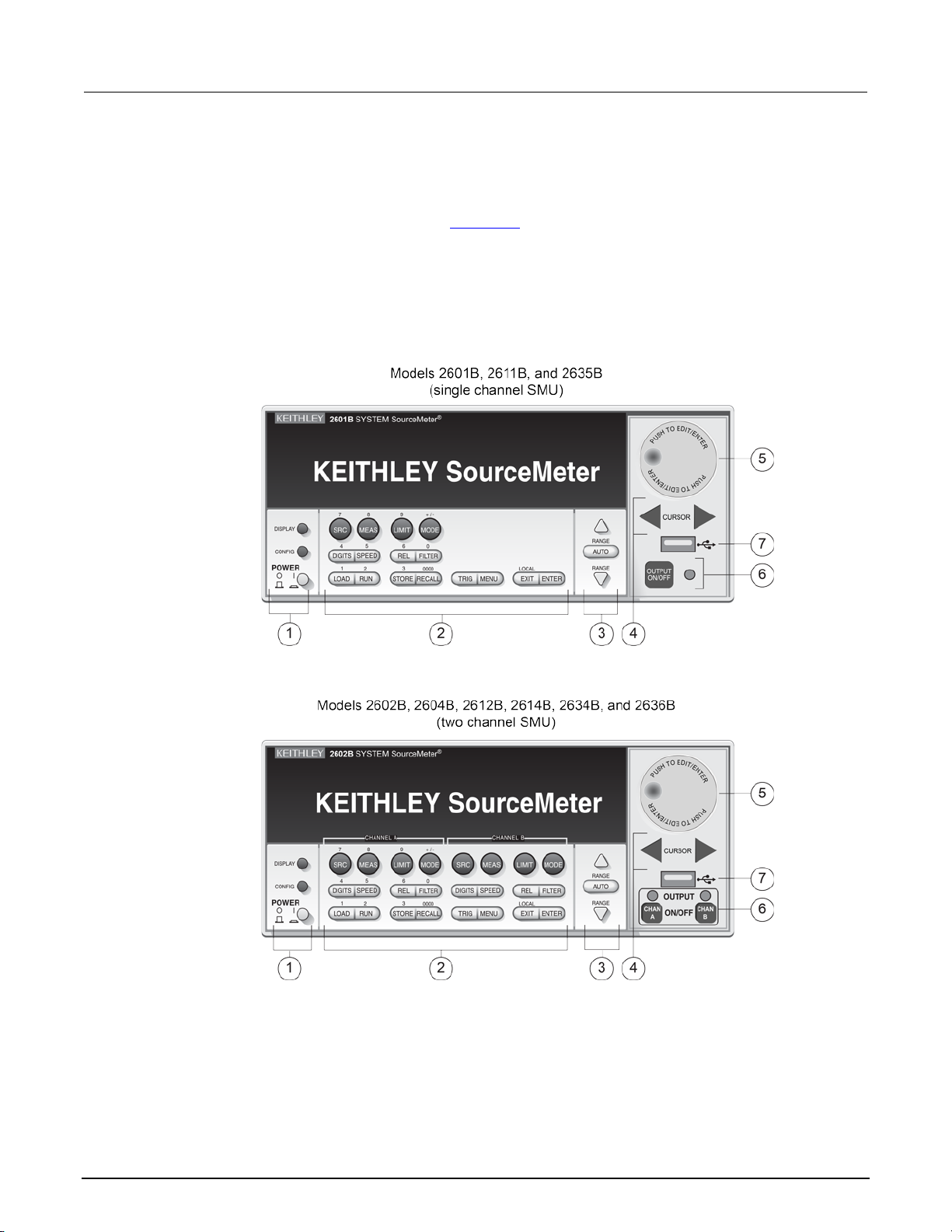
Section
Reference Manual
2: General operation Series 2600B System SourceMeter® Instrument
Controls, indicators, and connectors
Series 2600B controls, indicators, and the USB port are on the front panel. Make connections to the
Series 2600B through connectors on the rear panel (on page 2-6
Front panel
The front panel of the Series 2600B is shown below. The descriptions of the front-panel controls, USB
port, and indicators follow the figure.
Figure 1: Front panel (Series 2600B models)
).
2-2 2600BS-901-01 Rev. B / May 2013
Page 27
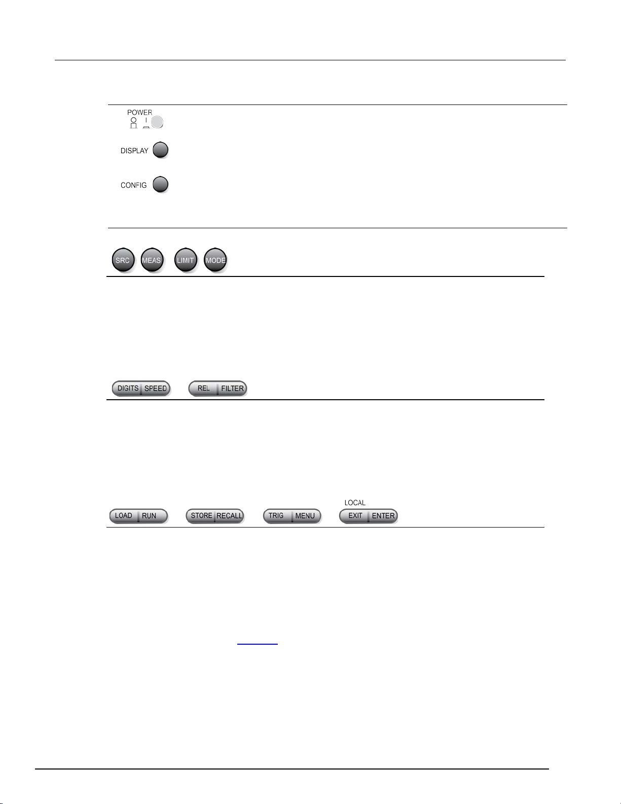
Series 2600B
General operation
Power switch. The in position turns the Series 2600B on (I); the out position turns it off (O).
Configures a function or operation.
SRC
MEAS
LIMIT
Places the cursor in the compliance limit field for editing. Also selects the limit value to edit (V, A,
MODE
DIGITS
Sets the display resolution (4½, 5½, or 6½ digits).
SPEED
Sets the measurement speed (FAST, MEDium, NORMAL, HI-ACCURACY, or OTHER). Speed
REL
Controls relative measurements, which allows a baseline value to be subtracted from a reading.
FILTER
Enables or disables the digital filter. You can use this filter to reduce reading noise.
LOAD
Loads test for execution (FACTORY, USER, or SCRIPTS).
RUN
Runs the last selected factory or user-defined test.
STORE
Accesses reading buffers and takes readings. TAKE_READINGS: Use to take readings and store
values, and timestamp values, if configured.
RECALL
Recalls information (DATA or STATISTICS) stored in a reading buffer: DATA includes stored
TRIG
Triggers readings.
MENU
Accesses the main menu (on page 2-17). The main menu can be used to configure many
functions and features.
EXIT
take the instrument out of remote operation.
ENTER
Accepts the selection and moves to the next choice or exits the menu.
System SourceMeter® Instrument Reference M anual Section 2:
1. Power switch, display and configuration keys
Toggles between the various source-measure displays and the user message mode.
2. SMU setup, performance control, special operation, and numbers
SMU (source-measure unit) setup
Selects the source function (V or A) and places the cursor in the source field for editing.
Cycles through measure functions (V, A, Ω, or W).
or W).
Selects a meter mode (I-METER, V-METER, OHM-METER, or WATT-METER).
Performance control
and accuracy are set by controlling the measurement aperture.
Special operation
them in a reading buffer. SAVE: Use to save a reading buffer to nonvolatile memory or to a userinstalled flash drive (USB1) in CSV or XML format. Readings include measurements, source
readings, and if configured, source values and timestamp values; STATISTICS includes MEAN,
STD DEV, SAMPLE SIZE, MINIMUM, MAXIMUM, PK-PK.
2600BS-901-01 Rev. B / May 2013 2-3
Cancels the selection and returns to the previous menu or display. Also used as a LOCAL key to
Page 28
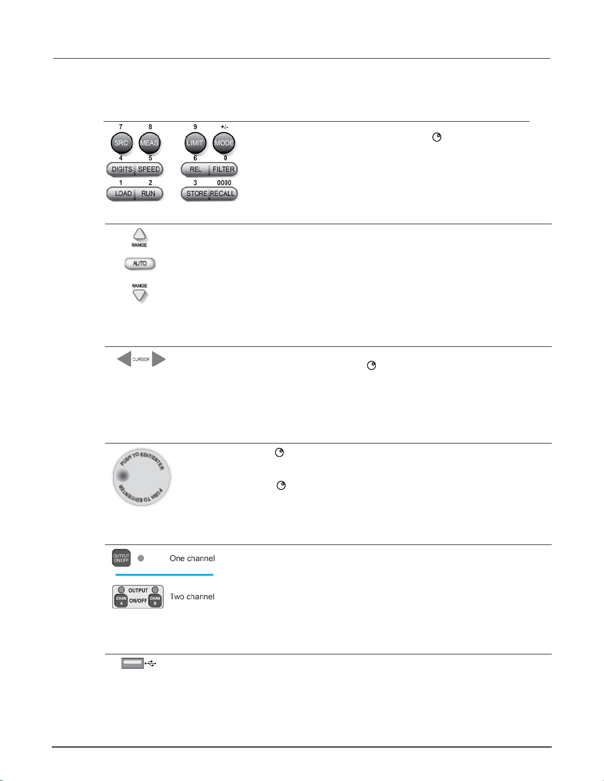
Section
Reference Manual
When enabled and in EDIT mode, the number keys (0-9, +/-, 0000) allow
Selects the next higher source or measure range.
In addition to selecting range functions, the up and down range keys change the format for
non-range numbers (as an example, when editing the limit value).
Use the CURSOR keys to move the cursor left or right. When the cursor is on the desired source
value or sub-menu item.
• Select a menu option or a value
Turns the source output on or off.
2: General operation Series 2600B System SourceMeter® Instrument
Number keys
direct numeric entry. Press the navigation wheel to enter EDIT mode.
3. Range keys
Enables or disables source or measure autorange.
Selects the next lower source or measure range.
4. Cursor keys
or compliance value digit, push the navigation wheel to enter edit mode, and turn the
navigation wheel to edit the value. Push the navigation wheel again when finished editing.
Use the CURSOR keys or the navigation wheel to move through menu items. To view a menu
value, use the CURSOR keys for cursor control, and then press the navigation wheel to view the
5. Navigation wheel
Turn the navigation wheel to:
• Move the cursor to the left and the right (the cursor indicates the selected value or item)
• While in edit mode, increase or decrease a selected source or compliance value
Push the navigation wheel to:
• Enable or disable edit mode for the selected source or compliance value
• Open menus and submenu items
6. Output control
7. USB port
Use the USB port to connect a USB flash drive to the instrument. You can use the USB flash drive
to store reading buffer data, scripts, and user setups. You can also use it to upgrade the firmware.
2-4 2600BS-901-01 Rev. B / May 2013
Page 29

Series 2600B
General operation
EDIT
Instrument is in editing mode
ERR
REM
Instrument is in remote mode
TALK
Instrument is addressed to talk
LSTN
Instrument is addressed to listen
SRQ
Service request is asserted
REL
FILT
Digital filter is enabled
AUTO
Source or measure autorange is selected
* (asterisk)
Readings are being stored in the buffer
System SourceMeter® Instrument Reference M anual Section 2:
8. Display indicators (not shown)
The items listed below represent the possible display indicators and their meanings.
Indicator Meaning
Questionable reading or invalid calibration step
Relative mode is enabled
2600BS-901-01 Rev. B / May 2013 2-5
Page 30
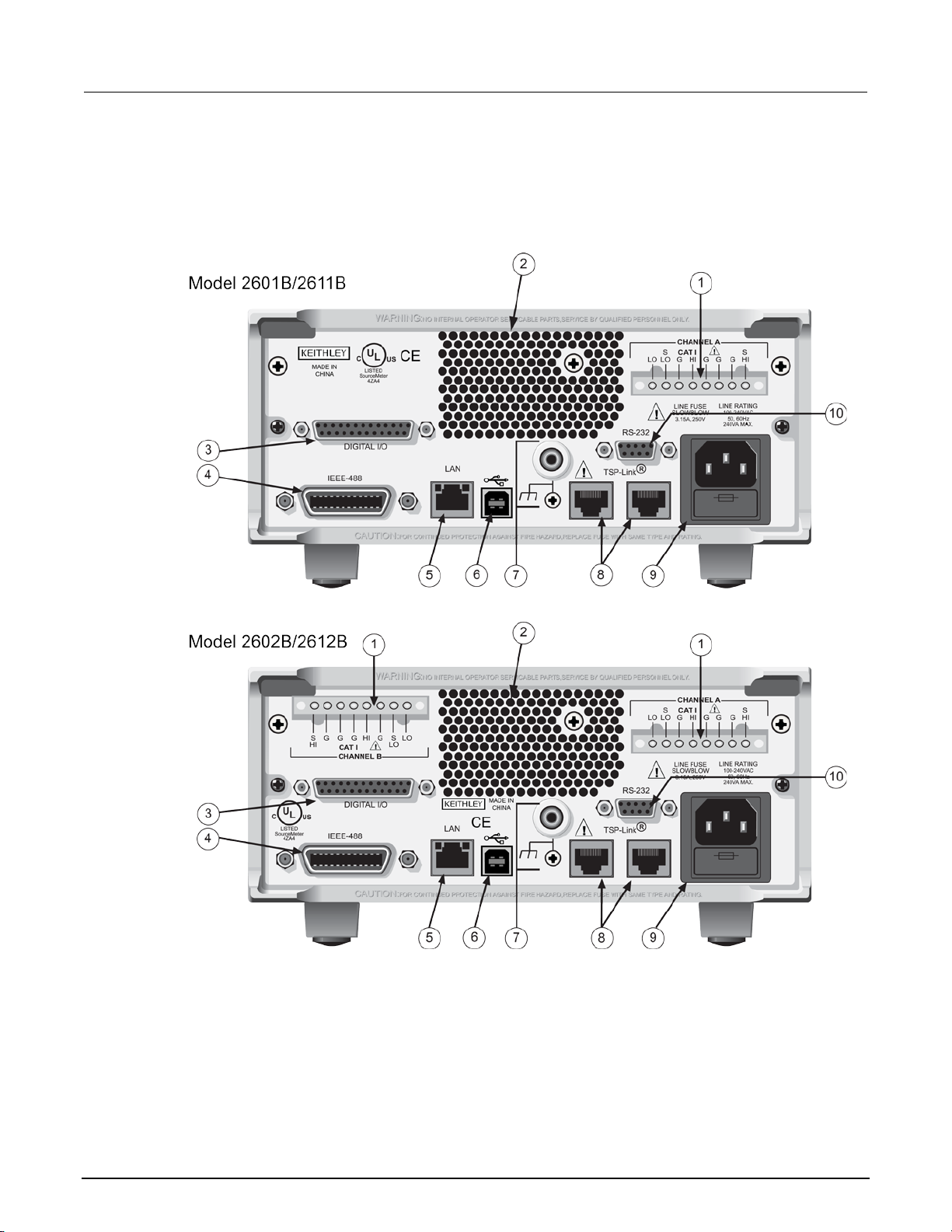
Section
Reference Manual
2: General operation Series 2600B System SourceMeter® Instrument
Rear panel
The rear panel of the Series 2600B is shown below. The descriptions of the rear-panel components
follow the figure.
Figure 2: Rear panel (Models 2601B, 2602B, 2611B, and 2612B)
2-6 2600BS-901-01 Rev. B / May 2013
Page 31
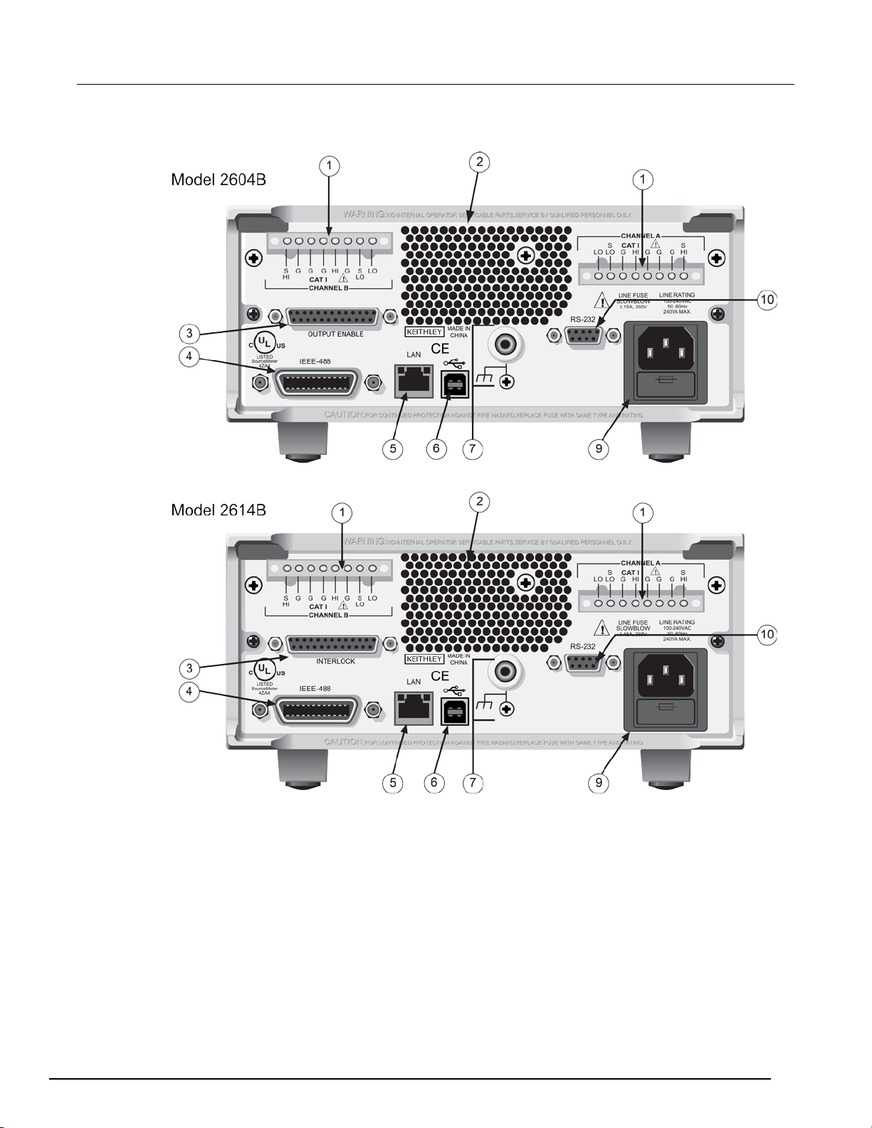
Series 2600B
General operation
System SourceMeter® Instrument Reference M anual Section 2:
Figure 3: Rear panel (Models 2604B and 2614B)
2600BS-901-01 Rev. B / May 2013 2-7
Page 32

Section
Reference Manual
2: General operation Series 2600B System SourceMeter® Instrument
Figure 4: Rear panel (Models 2634B and 2635B)
2-8 2600BS-901-01 Rev. B / May 2013
Page 33

Series 2600B
General operation
System SourceMeter® Instrument Referen ce Manual Section 2:
Figure 5: Rear panel (Model 2636B)
2600BS-901-01 Rev. B / May 2013 2-9
Page 34

Section
Reference Manual
Channel A
This connector provides input/output connections for HI and
Exhaust vent for the internal cooling fan. Keep the vent free of obstructions to
2: General operation Series 2600B System SourceMeter® Instrument
1. SMU connector
2601B/2602B/2604B/2611B/2612B/2614B
Channel B
2602B/2604B/2612B/2614B
Channel A
2634B/2635B/2636B
Channel B
2634B/2636B
LO, sense (S HI/S LO), and guard (G). Connections are as
follows:
LO = LO
S LO = Sense LO
G = Guard
S HI = Sense HI
HI = HI
These triaxial connectors provide input/output connections for
HI and LO, sense HI and sense LO, guard, and ground. See
connections at left. Each connector's conductors are as
follows:
* Center conductor
** Inner shield
*** Outer shield
2. Cooling exhaust vents
prevent overheating. Also see Cooling vents (on page 2-12).
2-10 2600BS-901-01 Rev. B / May 2013
Page 35

Series 2600B
General operation
2601B/2602B/2611B/2612B/2635B/2636B
Female DB-25 connector. Use a cable equipped with a male
DB-25 connector (Keithley Instruments part number CA-126-1).
Pins provided: Fourteen digital input or output pins, seven GND
2604B
Pins provided: One output enable pin, seven GND pins, and
2614B/2634B
Pins provided: One interlock pin, seven GND pins, and three
the Models 2614B and 2634B.
Connector for IEEE-488 (GPIB) operation. Use a shielded cable, such as the
This USB-2.0 receptacle (Type B) located on the rear panel is used to connect
2635B
2634B/2636B
System SourceMeter® Instrument Reference M anual Section 2:
3. Digital I/O
pins, and three +5 V pins .
The Models 2601B and 2602B have an output enable pin. The
Models 2611B, 2612B, 2635B, and 2636B have an interlock pin.
three +5 V pins. The digital input and output pins are not
available on the Model 2604B.
+5 V pins. The digital input and output pins are not available on
4. IEEE-488
Keithley Instruments Model 7007-1 or Model 7007-2.
5. LAN
RJ-45 connector for a local area network (LAN). The LAN interface supports
Auto-MDIX, so either a CAT-5 cross-over cable (provided), or a normal CAT-5
straight-through cable (not provided) can be used.
6. USB port
the instrument to a computer. You can use this connection to send commands to
the instrument.
7. Ground
2601B/2602B/2604B/2611B/2612B/2614B
Ground jack for connecting output HI or LO to chassis ground.
Ground screw for connections to chassis ground.
Triaxial connector on ground module.
Phoenix connector on ground module.
2600BS-901-01 Rev. B / May 2013 2-11
Page 36

Section
Reference Manual
Expansion interface that allows a Series 2600B and other TSP-enabled
Contains the AC line receptacle and power line fuse. The instrument can operate
Female DB-9 connector. For RS-232 operation, use a straight-through (not null
connection to the computer.
2: General operation Series 2600B System SourceMeter® Instrument
8. TSP-Link
instruments to trigger and communicate with each other. Use a category 5e or
higher LAN crossover cable (Keithley Instruments part number CA-180-3A).
The TSP-Link is not available on the Models 2604B, 2614B, and 2634B.
9. Power module
on line voltages of 100 V to 240 V AC at line frequencies of 50 Hz or 60 Hz.
10. RS-232
Cooling vents
The Series 2600B has side and top intake and rear exhaust vents. One side must be unobstructed to
dissipate heat.
Excessive heat could damage the Series 2600B and degrade its performance. Only operate the
Series 2600B in an environment where the ambient temperature does not exceed 50 °C (122 °F).
Do not place a container of liquid (water or coffee, for instance) on the top cover. If it spills, the liquid
may enter the case through the vents and cause severe damage.
modem) DB-9 shielded cable (Keithley Instruments Model 7009-5) for
2-12 2600BS-901-01 Rev. B / May 2013
Page 37

Series 2600B
General operation
System SourceMeter® Instrument Reference M anual Section 2:
To prevent damaging heat build-up and ensure specified performance, use the following guidelines.
The rear exhaust vent and either the top or both side intake vents must be unobstructed to properly
dissipate heat. Even partial blockage could impair proper cooling.
DO NOT position any devices adjacent to the Series 2600B that force air (heated or unheated)
toward its cooling vents or surfaces. This additional airflow could compromise accuracy.
When rack mounting the Series 2600B, make sure there is adequate airflow around both sides to
ensure proper cooling. Adequate airflow enables air temperatures within approximately one inch of
the Series 2600B surfaces to remain within specified limits under all operating conditions.
Rack mounting high power dissipation equipment adjacent to the Series 2600B could cause
excessive heating to occur. To produce specified Series 2600B accuracies, maintain the specified
ambient temperature around the surfaces of the Series 2600B. Proper cooling practice, in rack
configurations with convection cooling only, places the hottest non-precision equipment (for example,
the power supply) at the top of the rack away from and above precision equipment (such as the
Series 2600B).
Mount precision equipment as low as possible in the rack, where temperatures are coolest. Adding
space panels above and below the Series 2600B will help provide adequate airflow.
Turning your instrument on and off
The following topics describe how to power your instrument on and off, place an instrument in
standby, and configure the line freque nc y.
Procedure
The Series 2600B operates from a line voltage of 100 V to 240 V at a frequency of 50 Hz or 60 Hz.
Line voltage is automatically sensed (there are no switches to set). Make sure the operating voltage
in your area is compatible.
Follow the procedure below to connect the Series 2600B to line power and turn on the instrument.
Operating the instrument on an incorrec t lin e voltag e may cause damage to the instrument, possibly
voiding the warranty.
To turn a Series 2600B on and off:
1. Before plugging in the power cord, make sure that the front panel POWER switch is in the off (O)
position.
2. Connect the female end of the supplied power cord to the AC receptacle on the rear panel.
3. Connect the other end of the power cord to a grounded AC outlet.
2600BS-901-01 Rev. B / May 2013 2-13
Page 38

Section
Reference Manual
3-89
2: General operation Series 2600B System SourceMeter® Instrument
The power cord supplied with the Series 2600B contains a separate protective earth (safety
ground) wire for use with grounded outlets. When proper connections are made, the
instrument chassis is connected to power-line ground through the ground wire in the power
cord. In addition, a protective earth (safety ground) connection is provided through a screw
on the rear panel. In the event of a failure, not using a properly grounded protective earth
(safety ground) or grounded outlet may result in personal injury or death due to electric
shock.
4. To turn your instrument on, press the front panel POWER switch to place it in the on (I) position.
5. To turn your instrument off, press the front panel POWER switch to place it in the off (O) position.
Placing a Series 2600B in standby
Placing the Series 2600B in standby does not place the instrument in a safe state (an
Interlock
When the instrument is on, the output may be placed in an active output state (output on) or a
standby mode (output off). From the front panel, pressing the OUTPUT ON/OFF control toggles the
output using the present instrument configuration. You can also place the output in standby over the
remote interface by sending the following command:
smuX.source.output = 0
(on page
) is provided for this function).
Warmup period
The Series 2600B must be turned on and allowed to warm up for at least two hours to achieve rated
Even though the instrument is placed in standby, the output may not be actually off.
accuracies.
2-14 2600BS-901-01 Rev. B / May 2013
Page 39

Series 2600B
General operation
System SourceMeter® Instrument Reference M anual Section 2:
Line frequency configuration
The factory configures the Series 2600B to automatically detect the power line frequency (either
50 Hz or 60 H z) at each po wer -up. This detected line frequency is used for aperture (NPLC)
calculations.
In noisy environments, you can manually configure the instrument to match the actual line frequency.
To configure the line frequency from the front panel:
1. Press the MENU key, then turn the navigation wheel to select LINE-FREQ, and then press the
ENTER key.
2. Turn the navigation wheel to select the appropriate frequency and then press the ENTER key.
To configure the instrument to automatically detect line frequency at each power-up, select
AUTO.
3. Press the EXIT (LOCAL) key to back out of the menu structure.
To configure the line frequency from a remote interface:
Set the localnode.linefreq or the localnode.autolinefreq attribute. The following
programming example illustrates how to set the line frequency to 60 Hz:
localnode.linefreq = 60
The following programming example illustrates how to remotely configure the instrument to
automatically detect line frequency at each power-up:
localnode.autolinefreq = true
Fuse replacement
A rear panel fuse drawer is located below the AC receptacle (refer to Rear panel (on page 2-6)). This
fuse protects the power line input of the instrument. If the line fuse needs to be replaced, refer to Line
fuse replacement (on page A-1).
System information
You can display the serial number, firmware revision, calibration dates, and memory usage by
selecting SYSTEM-INFO from the main menu.
To view the system information from the front panel:
1. Press the MENU key.
2. Select SYSTEM-INFO.
3. Select one of the following:
• FIRMWARE
• SERIAL#
• CAL
• MEMORY-USAGE
To retrieve system information from a remote interface:
To retrieve the firmware revision and serial number, send the *IDN? query (see Identification query:
*IDN? (on page D-3) for more information).
2600BS-901-01 Rev. B / May 2013 2-15
Page 40

Section
Reference Manual
2: General operation Series 2600B System SourceMeter® Instrument
Menu overview
Menu navigation
To navigate through the menus and submenus, the Series 2600B must not be in edit mode (the EDIT
indicator is not illuminated).
Selecting menu items
To navigate the Main and Configuration menus, use the editing keys as follows:
• Press either CURSOR arrow key to highlight an option.
• Rotate the navigation wheel (clockwise or counter-clockwise) to highlight an option.
• Press the ENTER key (or the navigation wheel ) to select an option.
• Use the EXIT (LOCAL) key to cancel changes or to return to the previous menu or display.
For quick menu navigation, turn the navigation wheel to highlight an option and then press the
navigation wheel to select the highlighted option.
Menu trees
You can configure instrument operation through the menus that are accessed from the front panel.
2-16 2600BS-901-01 Rev. B / May 2013
Page 41

Series 2600B
General operation
System SourceMeter® Instrument Reference Manual Section 2:
Main menu
The main menu structure is summarized in the following figure and table. For other menu items, see
Configuration menus (on page 2-19
).
Figure 6: Main menu tree
2600BS-901-01 Rev. B / May 2013 2-17
Page 42
Section
Reference Manual
SCRIPT
Saves and recalls users scripts
Manage scripts (on page 6-3)
- LOAD
Loads scripts into nonvolatile memory
- SAVE
Saves scripts
SETUP
Saves and recalls user and factory setup options
Saved setups (on page 2-46)
- RECALL
Recalls user setup options
- POWERON
Sets the configuration used during startup
GPIB
- ADDRESS
Configures the address for the GPIB interface
- ENABLE
Enables and disables the GPIB interface
LAN
Configures the local area network (LAN)
LAN concepts and settings (on page C-1)
- STATUS
Displays LAN connection status
- CONFIG
Configures the LAN IP address and gateway
- APPLY_SETTINGS
Applies changes made using the CONFIG menu
- ENABLE
Enables and disables the LAN interface
RS232
Controls the options for the RS-232 interface
Remote communication interfaces (on
- BAUD
Sets the baud rate
- BITS
Configures the number of bits
- FLOW-CTRL
Configures the flow control
- ENABLE
Enables and disables the RS-232 interface
TSPLINK
1
TSP-Link system expansion interface (on
- NODE
Selects the instrument node identifier
- RESET
Resets the TSP-Link network
UPGRADE
Upgrades the firmware from a USB flash drive
Upgrading the firmware (on page A-4)
DISPLAY
Accesses display functions
Front panel tests (on page A-2)
- TEST
Runs the display test
See Numeric entry method in S et ting a
- NUMPAD
Enables and disables the numeric keypad
DIGOUT
2
Controls digital outputs
Digital I/O (on page 3-83)
- DIG-IO-OUTPUT
Selects the digital I/O values
- WRITE-PROTECT
Write-protects specific digital I/O lines
BEEPER
- ENABLE
Enables the key beeps
- DISABLE
Disables the key beeps
LINE-FREQ
- 50Hz
Set the line frequency to 50 Hz
- 60Hz
Set the line frequency to 60 Hz
- AUTO
Enables automatic line frequency detection during
start up
SYSTEM-INFO
Displays the system information
General operation (on page 2-1)
- FIRMWARE
Displays the version of firmware installed
- CAL
Displays the last calibration date
- MEMORY-USAGE
Displays memory usage in percentage
1. TSPLINK is not available on the Models 2604B, 2614B, and 2634B.
2. DIGOUT is not available on the Models 2604B, 2614B, and 2634B.
2: General operation Series 2600B System SourceMeter® Instrument
The following table contains descriptions of the main menu options and cross-references to related
information. To access a menu option, press the MENU key, turn the navigation wheel to move the
cursor to select an item, and press the navigation wheel .
Menu selection Description For more information, see:
- SAVE Saves user setup options
Configures the GPIB interface options
- RESET Restores the default settings
- PARITY Sets the parity
Configure the instrument in a TSP-Link® network
Remote communicatio n interfaces (on
page 2-89)
page 2-89)
page 6-47)
value (on page 2-21)
Controls the key beeps General operation (on page 2-1)
Configures the line frequency General operation (on page 2-1)
- SERIAL# Displays the serial number of the unit
RESET-PASSWO RD
2-18 2600BS-901-01 Rev. B / May 2013
Resets the system password Password management (on page 6-34
)
Page 43

Series 2600B
General operation
System SourceMeter® Instrument Reference M anual Section 2:
Configuration menus
The configuration menu structure is summarized in the following figure and table. For directions on
navigating the menu, see Menu navigation (on page 2-16
page 2-17).
Figure 7: CONFIG menu tree (models with a single SMU)
). For other menu items, see Main menu (on
2600BS-901-01 Rev. B / May 2013 2-19
Page 44

Section
Reference Manual
2: General operation Series 2600B System SourceMeter® Instrument
Figure 8: CONFIG menu tree (models with two SMUs)
2-20 2600BS-901-01 Rev. B / May 2013
Page 45

Series 2600B
General operation
SRC
V-source sense, low range;
Range (on page 2-82), Basic source -
ME AS
autozero
LIMIT
V-source and I-source
compli a nce limits
Limits (on page 2-27)
SPEED
Measurement speed (NPLC)
Speed (on page 2-88)
REL
Set relative values
Relative offset (on page 3-1)
FILTER
Control digital filter
Filters (on page 3-3)
OUTPUT ON/OFF
Set off-state, control digital
I/O
Output-off states (on page 2-77)
TRIG
Set trigger in, count, interval,
and delay
Triggering (on page 3-32)
STORE
Set buffer count and
destination
Source-measure concepts (on page 4-1)
System SourceMeter® Instrument Reference M anual Section 2:
Press the EXIT key to return to a previous menu.
The following table contains descriptions of the configuration menus, as well as cross-references to
related information. To select a menu for single SMU instruments, press the CONFIG key and then
the front-panel key associated with the menu (see the description column in the following table). For
two-SMU instruments, press the CONFIG key, select the appropriate channel (CHANNEL-A,
CHANNEL-B) and then the front-panel key associated with the menu. To select TRIG and STORE
menus on two-SMU instruments, press the CONFIG key and then select COMMON instead of
selecting a channel.
To access, press the CONFIG
key and then:
V and I-measure range, V-
Options For more information, see:
I-source low range; and
highC mode
measure sense, low range;
measure procedure (on page 2-32)
Range (on page 2-82), Basic source measure procedure (on page 2-32)
Setting values
Setting a value
You can adjust a value using either the Navigation wheel method or Numeric entry method (using
the keypad).
Navigation wheel method:
1. Use the CURSOR arrow keys (or turn the navigation wheel ) to move the cursor to the digit that
needs to be changed.
2. Press the navigation wheel or the ENTER key to enter edit mode. The EDIT indicator is
illuminated.
3. Rotate the navigation wheel to set the appropriate value.
4. Press the ENTER key to select the value or press the EXIT (LOCAL) key to cancel the change.
5. To return to the main menu, press the EXIT (LOCAL) key.
2600BS-901-01 Rev. B / May 2013 2-21
Page 46

Section
Reference Manual
2: General operation Series 2600B System SourceMeter® Instrument
Numeric entry method:
The numeric entry method may only be used if the numeric keypad is enabled.
To set a value to zero, press the 0000 numeric entry key. To toggle the polarity of a value, press the
+/– numeric entry key.
1. If the keypad is disabled, press the MENU key, then select DISPLAY > NUMPAD > ENABLE.
2. Use the CURSOR arrow keys (or turn the navigation wheel ) to move the cursor to the value
that needs to be changed.
3. Press the navigation wheel or the ENTER key to enter edit mode. The EDIT indicator is
illuminated.
4. Press any of the number keys (0-9, +/-, 0000) (see 2. SMU setup, performance control, special
operation, and numbers (on page 2-3)). The cursor moves to the next digit on the right.
5. Repeat the above steps as required to set the values.
6. Press the ENTER key to select the value or press the EXIT (LOCAL) key to cancel the change.
7. To return to the main menu, press the EXIT (LOCAL) key.
Setting source and compliance values
When the Series 2600B is in the edit mode (EDIT indicator is on), the editing controls are used to set
source and compliance values. Note that when you edit the source value, source autoranging is
turned off and remains off until you turn it on again.
To cancel source editing, press the EXIT (LOCAL) key.
To edit the source value:
1. Press the SRC key. The cursor flashes in the source value field.
2. Use the CURSOR keys (or turn the navigation wheel ) to move the cursor to the digit that
needs to be changed.
3. Press the navigation wheel or the ENTER key to edit the source value. The EDIT indicator is
illuminated.
4. Change the source value (see Setting values (on page 2-21
The +/- key toggles the polarity. The 0000 key sets the value to 0.
5. When finished, press the ENTER key (the EDIT indicator is not illuminated).
)).
2-22 2600BS-901-01 Rev. B / May 2013
Page 47

Series 2600B
General operation
Beeper
System SourceMeter® Instrument Reference M anual Section 2:
To edit compliance limit values:
1. Press the LIMIT key.
2. Use the CURSOR keys (or turn the navigation wheel ) to move the cursor to the digit that
needs to be changed.
3. Press the navigation wheel or the ENTER key to enter edit mode. The EDIT indicator is
illuminated.
4. Change the compliance value (see Setting values ( on page 2-21
)).
5. When finished, press the ENTER key (the EDIT indicator is not illuminated).
The up and down range keys change the format of the limit value.
The Series 2600B includes a beeper. When it is enabled, a beep indicates one of the following
actions have occurred:
• A front-panel key was pressed: A short beep, similar to a key click, is issued.
• The navigation wheel was turned or pressed: A short beep is issued.
• The output source was changed: A longer beep is issued when you press the OUTPUT ON/OFF
control (turn the output on or off).
To turn the beeper on or off from the front panel:
1. Press the MENU key, and then select BEEPER.
2. Select one of the following:
• ENABLE
• DISABLE
To turn the beeper on or off from the TSP command interface:
2600BS-901-01 Rev. B / May 2013 2-23
Set the beeper.enable attribute. For example, to enable the beeper, send:
beeper.enable = 1
Page 48

Section
Reference Manual
2: General operation Series 2600B System SourceMeter® Instrument
Display mode
Use the DISPLAY key to scroll through the various display modes shown in the figure below. Refer to
Display operations (on pag e 3-71
For the Models 2602B, 2604B, 2612B, 2614B, 2634B, and 2636B only, press the DISPLAY key more
than once to cycle through the dual channel and single channel display modes. This applies to
CHANNEL A (SMU A) and C HAN N EL B ( SMU B).
The Models 2601B, 2611B, and 2635B have a single channel (SMU A).
) for more information about the display.
Figure 9: Display modes
Basic operation
For the Models 2611B, 2612B, 2614B, 2634B, 2635B, and 2636B, hazardous voltages may
be present on all output and guard terminals. To prevent electrical shock that could cause
injury or death, never make or break connections to the Series 2600B while the instrument
is powered on. Turn off the equipment from the front panel or disconnect the main power
cord from the rear of the Series 2600B before handling cables. Putting the equipment into
standby does not guarantee that the outputs are powered off if a hardware or software fault
occurs.
2-24 2600BS-901-01 Rev. B / May 2013
Page 49

Series 2600B
General operation
System SourceMeter® Instrument Reference Manual Section 2:
Operation overview
Before you begin any of the following front panel procedures, make sure that you exit out of the
menu structure. Press the EXIT (LOCAL) key as many times as needed to return to the main
display.
Source-measure capabilities
From the front panel, the instrument can be configured to perform the following source-measure
operations:
• Source voltage: Measure and display current, voltage, resistanc e, or power
• Source current: Measure and display voltage, current, resistance, or power
• Measure resistance: Display resistance calculated from voltage and current components of
measurement (can optionally specify source voltage or source current value)
• Measure power: Display power calculated from voltage and current components of
measurement (can optionally specify source voltage or source current value)
• Measure only (V or I): Display voltage or current measurement
2600BS-901-01 Rev. B / May 2013 2-25
Page 50

Section
Reference Manual
100 mV
±101 mV
±102 mV
200 mV
±202 mV
±204 mV
200 mV
1.5 A
±202 mV
±204 mV
Max Power = 40.4 W per channel
Max Power = 30.603 W per channel
Max Power = 30.603 W per channel
1. 200 V source range available only when
3. 200 V source range available only when
Range
Source
Measure
Range
Source
Measure
Range
Source
Measure
1.5 A
2: General operation Series 2600B System SourceMeter® Instrument
Voltage and current
The following table lists the source and measure limits for the voltage and current functions. The full
range of operation is explained in Operating boundar ie s (on page 4-4
Source-measure capabilities
Model 2601B/2602B Model 2611B/2612B Model 2635B/2636B
Range Source Measure Range Source Measure Range Source Measure
).
1 V
6 V
40 V
100 nA
1 µA
10 µA
100 µA
1 mA
10 mA
100 mA
1 A
3 A
±1.01 V
±6.06 V
±40.4 V
±101 nA
±1.01 µA
±10.1 µA
±101 µA
±1.01 mA
±10.1 mA
±101 mA
±1.01 A
±3.03 A
±1.02 V
±6.12 V
±40.8 V
±102 nA
±1.02 µA
±10.2 µA
±102 µA
±1.02 mA
±10.2 mA
±102 mA
±1.02 A
±3.06 A
2 V
20 V
1
200 V
100 nA
1 µA
10 µA
100 µA
1 mA
10 mA
100 mA
1 A
1.5 A
10 A2
±2.02 V
±20.2 V
±202 V
±101 nA
±1.01 µA
±10.1 µA
±101 µA
±1.01 mA
±10.1 mA
±101 mA
±1.01 A
±1.515 A
±10.1 A
±2.04 V
±20.4 V
±204 V
±102 nA
±1.02 µA
±10.2 µA
±102 µA
±1.02 mA
±10.2 mA
±102 mA
±1.02 A
±1.53 A
±10.2 A
2 V
20 V
3
200 V
100 pA
1 nA
10 nA
100 nA
1 µA
10 µA
100 µA
1 mA
10 mA
100 mA
1 A
±2.02 V
±20.2 V
±202 V
N/A
±1.01 nA
±10.1 nA
±101 nA
±1.01 µA
±10.1 µA
±101 µA
±1.01 mA
±10.1 mA
±101 mA
±1.01 A
±1.515 A
interlock is enabled. See Digital I/O (on page
3-83).
2. 10 A range available only in pulse mode.
interlock is enabled. See Digital I/O (on page 3-
83).
Source-measure capabilities
Model 2601B/2602B/2604B Model 2611B/2612B/2614B Model 2635B/2636B
±2.04 V
±20.4 V
±204 V
±102 pA
±1.02 nA
±10.2 nA
±102 nA
±1.02 µA
±10.2 µA
±102 µA
±1.02 mA
±10.2 mA
±102 mA
±1.02 A
±1.53 A
100 mV
1 V
6 V
40 V
100 nA
1 µA
10 µA
100 µA
1 mA
10 mA
100 mA
1 A
3 A
2-26 2600BS-901-01 Rev. B / May 2013
±101 mV
±1.01 V
±6.06 V
±40.4 V
±101 nA
±1.01 µA
±10.1 µA
±101 µA
±1.01 mA
±10.1 mA
±101 mA
±1.01 A
±3.03 A
±102 mV
±1.02 V
±6.12 V
±40.8 V
±102 nA
±1.02 µA
±10.2 µA
±102 µA
±1.02 mA
±10.2 mA
±102 mA
±1.02 A
±3.06 A
200 mV
2 V
20 V
1
200 V
100 nA
1 µA
10 µA
100 µA
1 mA
10 mA
100 mA
1 A
1.5 A
10 A2
±202 mV
±2.02 V
±20.2 V
±202 V
±101 nA
±1.01 µA
±10.1 µA
±101 µA
±1.01 mA
±10.1 mA
±101 mA
±1.01 A
±1.515 A
±10.1 A
±204 mV
2.04 V
±
±20.4 V
±204 V
±102 nA
±1.02 µA
±10.2 µA
±102 µA
±1.02 mA
±10.2 mA
±102 mA
±1.02 A
±1.53 A
±10.2 A
±202 mV
±2.02 V
±20.2 V
±202 V
N/A
±1.01 nA
±10.1 nA
±101 nA
±1.01 µA
±10.1 µA
±101 µA
±1.01 mA
±10.1 mA
±101 mA
±1.01 A
200 mV
2 V
20 V
3
200 V
100 pA
1 nA
10 nA
100 nA
1 µA
10 µA
100 µA
1 mA
10 mA
100 mA
1 A
±1.515 A
±204 mV
±2.04 V
±20.4 V
±204 V
±102 pA
±1.02 nA
±10.2 nA
±102 nA
±1.02 µA
±10.2 µA
±102 µA
±1.02 mA
±10.2 mA
±102 mA
±1.02 A
±1.53 A
Page 51

Series 2600B
General operation
Max Power = 40.4 W per channel
Max Power = 30.603 W per channel
Max Power = 30.603 W per channel
Source
range
Maximum
limit
Source
range
Maximum
limit
Source
range
Maximum
limit
100 nA
40 V
100 nA
200 V
1 nA
200 V
System SourceMeter® Instrument Reference M anual Section 2:
1. 200 V source range available only when
interlock is enabled. See Digital I/O (on page
3-83).
2. 10 A range available only in pulse mode.
3. 200 V source range available only when
interlock is enabled. See Digital I/O (on page 3-
83).
Limits
When sourcing voltage, the Series 2600B can be set to limit current or power. Conversely, when
sourcing current, the Series 2600B can be set to limit voltage or power. In steady-state conditions, the
Series 2600B output will not exceed the limit. The maximum limit is the same as the maximum values
listed in the following table.
The limit circuit will limit in either polarity regardless of the polarity of the source or limit value. The
accuracy of the limit opposite in polarity from the source is diminished unless the instrument is in sink
mode (on page 2-29). The maximum limits are based on source range. For more information, see
Compliance limit principles (on page 4-2).
The limit operation of the instrument changes dependent on the source mode (current or voltage),
load, and the configured limits (current, voltage, and power). It is important to distinguish both the
current and voltage limits from the power limit. As the names imply, the current limit restricts the
current for sourced voltage, and the voltage limit restricts the voltage for a sourced current. The
power limit, however, restricts power by lowering the present limit in effect (voltage or current) as
needed to restrict the SMU from exceeding the specified power limit. For additional details on using
limits, including load considerations when specifying both a current (or a voltage) limit and a power
limit, see Operating boundaries (on page 4-4
).
The only exception to the limit not being exceeded is the VLIMIT when operating as an ISOURCE.
To avoid excessive (and potentially destructive) currents from flowing, the VLIMIT will source or sink
up to 102 mA for ISOURCE ranges on or below 100 mA. For the ranges 1 A and above, the
maximum current allowed is the current source setting.
Maximum limits
Model 2601B/2602B/2604B Model 2611B/2612B/2614B Model 2634B/2635B/2636B
100 mV
1 V
6 V
40 V
1 µA
10 µA
100 µA
1 mA
10 mA
100 mA
1 A
3 A
3 A
3 A
3 A
1 A
40 V
40 V
40 V
40 V
40 V
40 V
40 V
6 V
200 mV
2 V
20 V
200 V
1 µA
10 µA
100 µA
1 mA
10 mA
100 mA
1 A
1.5 A
1.5 A
1.5 A
1.5 A
100 mA
200 V
200 V
200 V
200 V
200 V
200 V
20 V
20 V
200 mV
2 V
20 V
200 V
10 nA
100 nA
1 µA
10 µA
100 µA
1 mA
10 mA
100 mA
1 A
1.5 A
1.5 A
1.5 A
1.5 A
100 mA
200 V
200 V
200 V
200 V
200 V
200 V
200 V
200 V
20 V
20 V
2600BS-901-01 Rev. B / May 2013 2-27
Page 52

Section
Reference Manual
smuX.source.limiti = limit
Set current limit.
smuX.source.limitv = limit
smuX.source.limitp = limit
Set power limit.
compliance = smuX.source.compliance
Test if in limit (true = in limit; false =
smu
smua
SMU Channel B).
2: General operation Series 2600B System SourceMeter® Instrument
Setting the limit
Front-panel limit
Set the limit from the front panel as follows:
1. For the Model 2601B/2611B/26 35 B or the Model 260 2 B/26 04 B/2 612 B/2 614 B/ 263 4B/2 636 B
single-channel display mode, press the LIMIT key to directly access limit editing. Pressing the
LIMIT key while in limit edit mode will toggle the display between the complementary function limit
and the power limit display.
2. For the Model 2602B/2604B/26 12 B/2 614 B/2 634 B/ 263 6B, dua l-channel display mode, press the
3. Press the navigation wheel and set the limit to the new value.
4. Press the ENTER key or the navigation wheel to complete editing.
5. Press the EXIT (LOCAL) key to return to the main display.
Remote limit
The table below summarizes basic commands to program a limit. For a more complete description of
these commands, refer to the TSP command reference (on page 7-1
Limit commands
Command* Description
key, then select CURRENT, VOLTAGE, or POWER as needed. Press the ENTER key or
LIMIT
the navigation wheel .
).
Set voltage limit.
not in limit).
*
X: For Models 2601B, 2611B, and 2635B, this value is
2604B, 2612B, 2614B, 2634B, and 2636B, this value can be smua (for SMU Channel A) or smub (for
(SMU Channel A); for Models 2602B,
To set the limit, send the command with the limit value as the parameter. The following programming
example illustrates how to set the current, voltage, and power limit to 50 mA, 4 V, and 1 W
respectively:
smua.source.limiti = 50e-3
smua.source.limitv = 4
smua.source.limitp = 1
The following programming example illustrates how to print the limit state:
print(smua.source.compliance)
A returned value of true indicates one of three things:
• If the instrument is configured as a current source, the voltage limit has been reached
• If the instrument is configured as a voltage source, the current limit has been reached
2-28 2600BS-901-01 Rev. B / May 2013
Page 53

Series 2600B
General operation
System SourceMeter® Instrument Reference M anual Section 2:
Sink operation
Carefully consider and configur e the ap propr i ate outp u t -off state, source, and compliance limits
before connecting the Series 2600B to a device that can deliver energy (for example, other voltage
sources, batteries, capacitors, solar cells, or other Series 2600B instruments). Configure
recommended instrument settings before making connections to the device. Failure to consider the
output-off state, source, and compliance limits may result in damage to the instrument or to the
device under test (DUT).
When operating as a sink (V and I have opposite polarity), the SourceMeter instrument is dissipating
power rather than sourcing it. An external source (for example, a battery) or an energy storage device
(for example, a capacitor) can force operation into the sink region.
The accuracy of the limit opposite in polarity from the source is diminished unless the instrument is in
sink mode. Also see Compliance limit principles ( on pa ge 4-2).
For example, if a 12 V battery is connected to the V-Source (HI to battery +) that is programmed for
+10 V, sink operation will occur in the second quadrant (source +V and measure -I).
When using the I-Source as a sink, ALWAYS set V-Compliance to a level that is higher than the
external voltage level. Failure to do so could result in excessive current flow into the Series 2600B
and incorrect measurements. See Limits (on page 2-27) for details about compliance limit.
The only exception to the compliance limit not being exceeded is the V-Limit when operating as an ISource. To avoid excessive (and potentially destructive) currents from flowing, the V-Limit will source
or sink up to 102 mA for I-Source ranges on or below 100 mA. For the ranges 1 A and abo ve, the
maximum current allowed is the current source setting.
The sink operating limits are shown in Continuous power operating boundaries (on page 4-5).
Sink mode
When operating as a sink, limit inaccuracies are introduced. Enabling sink mode reduces the source
limit inaccuracy seen when operating in quadrants II and IV (quadrants I and III will show this source
limit inaccuracy).
Setting the sink mode using the front panel
To enable or disable the sink mode from the front panel:
1. Press the CONFIG key and then the SRC key.
2. Select V-SOURCE.
3. Select SINK-MODE.
4. Select ENABLE or DISABLE.
5. Push the ENTER key. Sink mode is enabled or disabled, as applicable.
6. Press the EXIT (LOCAL) key twice to return to the main display.
2600BS-901-01 Rev. B / May 2013 2-29
Page 54

Section
Reference Manual
2: General operation Series 2600B System SourceMeter® Instrument
Setting the sink mode from the remote interface
To enable or disable sink mode from the remote interface:
The programming example below illustrates how to enable sink mode (to disable, set the attribute to
smua.DISABLE):
smua.source.sink = smua.ENABLE
Fundamental circuit configurations
The fundamental source-measure configurations for the Series 2600B are shown in the following
figure. When sourcing voltage, you can measure current or voltage (see A: Source V). When sourcing
current, you can measure voltage or current (see B: Source I). See Basic circuit configurations (on
page 4-19) for detailed information.
Figure 10: Fundamental source-measure configurations
Operation considerations for the ADC
2-30 2600BS-901-01 Rev. B / May 2013
The following paragraphs disc uss autozero and N P LC c aching.
Page 55

Series 2600B
General operation
OFF
Turns automatic reference measurements off.
AUTO
Automatically takes new acquisitions when the Series 2600B determines
reference and zero values are out-of-date.
System SourceMeter® Instrument Reference M anual Section 2:
Autozero
The ADC of the Series 2600B uses a ratiometric A/D conversion technique. To ensure accuracy of
readings, the instrument must periodically obtain fresh measurements of its internal ground and
voltage reference. Separate reference and zero measurements are used for each aperture.
As summarized in the "Autozero settings" table, there are three different settings for autozero. By
default, the instrument automatically checks these reference measurements whenever a signal
measurement is made (AUTO). If the reference measurements are out of date when a signal
measurement is made, the instrument will automatically take two more A/D conversions, one for the
reference and one for the zero, before returning the result. Thus, occasionally, a measurement takes
longer than normal.
This extra time can cause problems in sweeps and other test sequences in which measurement
timing is critical. To avoid the extra time for the reference measurements in these situations, the OFF
selection can be used to disable the automatic reference measurements. Note that with automatic
reference measurements disabled, the instrument may gradually drift out of specification.
To minimize the drift, a reference and zero measurement should be made immediately before the
critical test sequence. The ONCE setting can be used to force a refresh of the reference and zero
measurements used for the current aperture setting.
Autozero settings
Autozero setting Description
ONCE
After immediately taking one reference and one zero measurement, turns
automatic reference measurements off.
Front-panel autozero
To change autozero from the front panel:
1. Press the CONFIG key.
2. Press the MEAS key.
3. Turn the navigation wheel to select AUTO-ZERO, and then press the ENTER key or the
navigation wheel .
4. Turn the navigation wheel to select the mode (OFF, ONCE, or AUTO), and then press the
ENTER key or the navigation wheel .
5. Press the EXIT (LOCAL) key to return to the previous display.
2600BS-901-01 Rev. B / May 2013 2-31
Page 56

Section
Reference Manual
smuX.measure.autozero = smuX.AUTOZERO_OFF
smuX.measure.autozero = smuX.AUTOZERO_ONCE
After immediately taking one reference and one zero
smuX.measure.autozero = smuX.AUTOZERO_AUTO
Automatically takes new acquisitions when the Series
date.
2614B, 2634B, and 2636B, this value can be smua (for SMU Channel A) or smub (for SMU Channel B).
2: General operation Series 2600B System SourceMeter® Instrument
Remote command autozero
To set autozero from a remote interface:
Use the autozero command with the appropriate option shown in the following table to set autozero
through a remote interface (see smuX.measure.autozero (on page 7-199
)). For example, send the
following command to activate channel A automatic reference measurements:
smua.measure.autozero = smua.AUTOZERO_AUTO
Autozero command and options
Command** Description
Disable autozero*
measurement, turns automatic reference measurements
off.
2600B determines reference and zero values are out-of-
* Old NPLC cache values will be used when autozero is disabled (see NPLC caching (on page 2-32)).
** smuX: For Models 2601B, 2611B, and 2635B, this value is smua (SMU Channel A); for Models 2602B, 2604B, 2612B,
NPLC caching
NPLC caching speeds up operation by caching A/D reference and zero values for up to the ten most
recent measurement aperture settings. Whenever the integration rate is changed using the SPEED
key, or a user setup is recalled, the NPLC cache is checked. If the integration rate is already stored in
the cache, the stored reference and zero values are recalled and used. If the integration rate is not
already stored in the cache, a reference and zero value will be acquired and stored in the cache when
the next measurement is made. If there are already ten NPLC values stored, the oldest one will be
overwritten by the newest one. When autozero is off, NPLC values stored in the cache will be used
regardless of age.
Basic source-measure procedure
Front-panel source-measure procedure
Use the following procedure to perform the basic source-measure operations of the Series 2600B.
The following procedure assumes that the Series 2600B is already connected to the device under test
(DUT), as explained in DUT test connections (on page 2-48
Hazardous voltages may be present on all output and guard terminals. To prevent electrical
shock that could cause injury or death, never make or break connections to the Series
2600B while the instrument is powered on. Turn off the equipment from the front panel or
disconnect the main power cord from the rear of the Series 2600B before handling cables.
Putting the equipment into standby does not guarantee that the outputs are powered off if a
hardware or software fault occurs.
).
2-32 2600BS-901-01 Rev. B / May 2013
Page 57

Series 2600B
General operation
System SourceMeter® Instrument Refer en ce Manual Section 2:
Step 1: Select and set the source level
Perform the following steps to select the source and edit the source value:
1. Press the SRC key as needed to select the voltage source or current source, as indicated by the
units in the source field on the display. The flashing digit (cursor) indicates which value is
presently selected for editing.
2. Move the cursor to the digit to change, then press the navigation wheel to enter the EDIT
mode, as indicated by the EDIT indicator.
3. Use the RANGE keys to select a range that will accommodate the value you want to set. See
Range (on page 2-82
) for more information. For best accuracy, use the lowest possible source
range.
4. Enter the source value.
5. Press the ENTER key or the navigation wheel to complete editing.
Step 2: Set the compliance limit
Perform the following steps to edit the compliance limit value:
1. If the instrument has two channels (Models 2602B, 2604B, 2612B, 2614B, 2634B, and 2636B)
and is in dual-channel display mode, perform the following (steps a, b, and c). Otherwise, go to
the next step.
a. Press the CONFIG key.
b. Press the LIMIT key and then select CURRENT or VOLTAGE.
c. Press the ENTER key or the navigation wheel .
2. If the instrument has only one channel (Models 2601B, 2611B, and 2635B), or if it is a
two-channel instrument that is in single-channel display mode, press the LIMIT key.
3. Move the cursor to the digit to change, then press the navigation wheel to enter the EDIT
mode, as indicated by the EDIT indicator.
4. Enter the limit value, then press the ENTER key or the navigation wheel to complete editing.
Step 3: Select the measurement function and range
Select measurement function and range as follows:
1. If the instrument has two channels (Models 2602B, 2604B, 2612B, 2614B, 2634B, and 2636B),
press the DISPLAY key to place it in single-channel-display mode (if not already). Otherwise, go
to the next step.
2. Select the measurement function by pressing the MEAS key.
3. Set the measurement range with the RANGE keys, or enable AUTO range. When setting the
range, consider the following points:
• When measuring the source (such as when sourcing V and measuring V), you cannot select the
measurement range using the RANGE keys. The selected source range determines the measurement
range.
• When not measuring the source (such as when sourcing V but measuring I), measurement range
selection can be done manually or automatically. When using manual ranging, use the lowest possible
range for best accuracy. When autorange is enabled, the Series 2600B automatically goes to the most
sensitive range to make the measurement.
Step 4: Turn the output on
2600BS-901-01 Rev. B / May 2013 2-33
Turn the output on by pressing the OUTPUT ON/OFF switch. The OUTPUT indicator light turns on.
Page 58

Section
Reference Manual
smuX.measure.autorangei = smuX.AUTORANGE_ON
Enable current measure autorange.
smuX.measure.autorangev = smuX.AUTORANGE_ON
Enable voltage measure autorange.
smuX.measure.autorangei = smuX.AUTORANGE_OFF
Disable current measure autorange.
smuX.measure.autorangev = smuX.AUTORANGE_OFF
Disable voltage measure autorange.
smuX.measure.rangei = rangeval
Set current measure range.
smuX.measure.rangev = rangeval
Set voltage measure range.
reading = smuX.measure.i()
Request a current reading.
reading = smuX.measure.v()
Request a voltage reading.
iReading, vReading = smuX.measure.iv()
Request a current and voltage reading.
reading = smuX.measure.r()
Request a resistance reading.
reading = smuX.measure.p()
smuX.source.autorangei = smuX.AUTORANGE_ON
Enable current source autorange.
smuX.source.autorangev = smuX.AUTORANGE_ON
Enable voltage source autorange.
smuX.source.autorangei = smuX.AUTORANGE_OFF
Disable current source autorange.
smuX.source.autorangev = smuX.AUTORANGE_OFF
Disable voltage source autorange.
smuX.source.func = smuX.OUTPUT_DCVOLTS
Select voltage source function.
smuX.source.func = smuX.OUTPUT_DCAMPS
Select current source function.
smuX.source.leveli = sourceval
Set current source value.
smuX.source.levelv = sourceval
Set voltage source value.
smuX.source.limiti = level
Set current limit.
smuX.source.limitv = level
Set voltage limit.
smuX.source.limitp = level
Set power limit.
smuX.source.output = smuX.OUTPUT_ON
Turn on source output.
smuX.source.output = smuX.OUTPUT_OFF
Turn off source output.
smuX.source.rangei = rangeval
Set current source range.
smuX.source.rangev = rangeval
Set voltage source range.
smuX.sense = smuX.SENSE_LOCAL
Select l ocal sense (2-wire).
smuX.sense = smuX.SENSE_REMOTE
Select remote sense (4-wire).
2634B, and 2636B, this value can be smua (for SMU Channel A) or smub (for SMU Channel B).
2: General operation Series 2600B System SourceMeter® Instrument
Step 5: Observe readings on the display.
Press the TRIG key if necessary to trigger the instrument to begin taking readings. The readings are
on the top line, and source and limit values are on the bottom line.
Step 6: Turn the output off
When finished, turn the output off by pressing the OUTPUT ON/OFF control. The OUTPUT indicator
light switches off.
Remote source-measure commands
Basic source-measurement procedures can also be performed through a remote interface. To do this,
send the appropriate commands. The following table summarizes basic source-measure commands.
See Introduction to TSP operation (on page 5-1
Basic source-measure commands
Command* Description
) for more information on using these commands.
Request a power reading.
* smuX: For Models 2601B, 2611B, and 2635B, this value is smua (SMU Channel A); for Models 2602B, 2604B, 2612B, 2614B,
2-34 2600BS-901-01 Rev. B / May 2013
Page 59

Series 2600B
General operation
System SourceMeter® Instrument Reference M anual Section 2:
Requesting readings
You can request readings by including the appropriate measurement command as the argument for
the print() command. The following programming example illustrates how to request a Channel A
current reading:
print(smua.measure.i())
Source-measure programming example
The following programming example illustrates the setup and command sequence of a basic
source-measure procedure with the following parameters:
• Source function and range: voltage, autorange
• Source output level: 5 V
• Current compliance limit: 10 mA
• Measure function and range: current, 10 mA
-- Restore Series 2600B defaults.
smua.reset()
-- Select voltage source function.
smua.source.func = smua.OUTPUT_DCVOLTS
-- Set source range to auto.
smua.source.autorangev = smua.AUTORANGE_ON
-- Set voltage source to 5 V.
smua.source.levelv = 5
-- Set current limit to 10 mA.
smua.source.limiti = 10e-3
-- Set current range to 10 mA.
smua.measure.rangei = 10e-3
-- Turn on output.
smua.source.output = smua.OUTPUT_ON
-- Print and place the current reading in the reading buffer.
print(smua.measure.i(smua.nvbuffer1))
-- Turn off output.
smua.source.output = smua.OUTPUT_OFF
2600BS-901-01 Rev. B / May 2013 2-35
Page 60

Section
Reference Manual
2: General operation Series 2600B System SourceMeter® Instrument
Triggering in local mode
It is not necessary to change any trigger settings to use the basic source and measurement
procedures covered in this section.
Press the MENU key, and then select SETUP > RECALL > INTERNAL > FACTORY to reset the
factory default conditions.
The following figure shows the general sequence for measurement triggering. The basic sequence is
as follows:
• When the output is turned on, the programmed source value is immediately applied to the device
under test (DUT).
• (Front panel operation only) If the immediate trigger source is selected, a measurement will be
triggered immediately. However, if the manual trigger source is selected, the front panel TRIG key
must be pressed.
• The instrument waits for the programmed delay period (if any).
• The instrument takes one measurement.
• If the number of measurements is less than the programmed trigger count, it cycles back to take
another measurement (the m eas ur em ent c ycle will be repeated ind ef initely if the infinite trigger
count is selected).
• For multiple measurements, the instrument waits for the programmed trigger interval (if any)
before taking the next measurement.
Figure 11: Local triggering
Configuring trigger attributes in local mode
From the front panel, press the CONFIG key, and then select TRIG. The following menu items are
shown:
TRIGGER-IN: Use these options to select the trigger-in source:
• IMMEDIATE: Triggering occurs immediately and the instrument starts to take measurements
when it is ready (for example, after the source output is turned on).
• MANUAL: The front panel TRIG key must be pressed to trigger the instrument to take readings.
2-36 2600BS-901-01 Rev. B / May 2013
Page 61

Series 2600B
General operation
System SourceMeter® Instrument Reference M anual Section 2:
COUNT: Sets the trigger count (number of measurements) as follows:
• FINITE: The instrument goes through measurement cycles for the programmed trigger count (1 to
99999).
• INFINITE: The instrument goes through measurement cycles indefinitely until halted.
INTERVAL: Sets the time interval between measurements (0 s to 999.999 s) when the count is
greater than 1.
Front-panel triggering example
DELAY: Sets the delay period between the trigger and the start of measurement (0 s to 999.999 s).
This example configures the trigger parameters to meet the following requirements:
• Manual triggering (TRIG key)
• Infinite trigger count (cycle indefinitely through measurement cycles)
• Interval (time between measurements): 1 s
• Delay (time from trigger to measurement): 2 s
To configure the trigger parameters:
1. Press the CONFIG key, and then the TRIG key.
2. Select TRIGGER-IN, and then press the ENTER key or the navigation wheel .
3. Select MANUAL, and then press the ENTER key or the navigation wheel .
4. Select COUNT, then select INFINITE, and then press the ENTER key or the navigation wheel .
5. Select INTERVAL, set the interval to 1 s, and then press the ENTER key or the nav igat ion wh ee l
.
6. Choose DELAY, set the delay to 2 s, and then press the ENTER key.
7. Use the EXIT (LOCAL) to return to the normal display.
8. Press the OUTPUT ON/OFF control to turn the output on.
9. Press TRIG. A 2 s delay occurs before the first measurement. The instrument cycles through
measurements indefinitely with a 1 s interval between m eas urem ent s.
10. Press the OUTPUT ON/OFF control again to stop taking readings.
2600BS-901-01 Rev. B / May 2013 2-37
Configuring for measure-only tests using the MODE key
In addition to being used for conventional source-measure operations, the Series 2600B can also be
used like a meter to measure current, voltage, resistance, or power.
To configure the Series 2600B as a V-meter, I-meter , ohm -meter, or watt-meter:
1. Press the MODE key.
2. Turn the navigation wheel to select the type of meter from the menu (I-METER, V-METER,
OHM-METER, or WATT-METER).
3. Press the ENTER key to complete the configuration of the Series 2600B as the selected meter.
Page 62

Section
Reference Manual
2: General operation Series 2600B System SourceMeter® Instrument
To manually configure the settings, refer to the applicable topics:
• V-meter and I-meter measurements (on page 2-38)
• Ohms measurements (on page 2-38)
• Power measurements (on page 2-42)
V-meter and I-meter measurements
To make V-meter and I-meter measurements without using the MODE key (such as when configuring
measure-only tests over the remote interface), follow the procedure below.
Perform the following steps to use the Series 2600B to measure voltage or current:
1. Select source-measure functions.
V-meter (voltmeter): Press the SRC key to select the I-source, and press the MEAS key to
select the voltage measurement function.
I-meter (ammeter): Press the SRC key to select the V-source, and press the MEAS key to select
the current measurement function.
2. Set source and compliance levels. To edit the source level, use the procedure provided in Step 1:
Select and set the source level (on page 2-33); to edit the compliance level, use the procedure
provided in Step 2: Set the complia nc e lim it (on page 2-33):
a. Select the lowest source range and set the source level to zero.
b. Set compliance to a level that is higher than the expected measurement.
When using the Series 2600B as a voltmeter, the voltage compliance limit must be set higher than
the voltage that is being measured. Failure to do this could result in excessive current flow into the
Series 2600B, incorrect measurements, and possible damage to the instrument.
3. Use the RANGE keys to select a fixed measurement range that will accommodate the expected
reading. Use the lowest possible range for best accuracy. You can also select autorange, which
will automatically set the Series 2600B to the most sensitive range.
4. Connect the voltage or current to be measured. Make sure to use 2-wire connections from the
Series 2600B to the device under test (DUT) (see DUT test connections (on page 2-48
)).
5. Press the OUTPUT ON/OFF control to turn the output on.
6. View the displayed reading (press the TRIG key if necessary).
7. When finished, press the OUTPUT ON/OFF control to turn the output off.
Ohms measurements
Ohms calculations
Resistance readings are calculated from the measured current and measured voltage as follows:
R = V/I
Where:
R is the calculated resistance
V is the measured voltage
I is the measured current
2-38 2600BS-901-01 Rev. B / May 2013
Page 63

Series 2600B
General operation
System SourceMeter® Instrument Reference M anual Section 2:
Ohms ranging
The front panel ohms function does not use ranging. The instrument formats a calculated resistance
reading (V/I) to best fit the display. There may be leading zeros if the ohms reading is less than 1 mΩ.
Basic ohms measurement procedure
When you use the MODE key to select ohms measurement, the Series 2600B is automatically
configured as a current source with a level of 1 mA. If you wish to change the source function, source
value, or compliance value (in other wor ds , if you wish to customize the MODE key's standard ohmmeter's configuration), then perform the following steps to perform ohms measurements. The
following procedure assumes that the Series 2600B is already connected to the device under test
To take an ohms measurement:
This procedure requires dual-channel instruments (Models 2602B, 2604B, 2612B, 2614B, 2634B,
and 2636B) to be placed in single-channel display mode. For these models, press the DISPLAY key
to select single-channel display mode. See Display mode (on page 2-24
1. Press the SRC key to select the source function.
2. Set the output source (current or voltage, dependent on which function is selected) to a value
based on the expected resistance. See Step 1: Select and set the source level (on page 2-33
earlier in this section.
3. Press the LIMIT key to edit the voltage or current limit. When programming a voltage limit, set the
voltage limit above the maximum expected voltage across the resistor under test. When
programming a current limit, set the current limit at or above the maximum expected current
through the resistor under test. See Step 2: Set the compliance limit (on page 2-33
(see DUT test connections (on page 2-48
section.
4. Press the MEAS key to display voltage or current.
5. Make sure that AUTO measurement range is on (press the AUTO key if needed).
6. Press the MEAS key as many times as needed to display ohms.
7. Press the OUTPUT ON/OFF control to turn the output on.
8. View the displayed reading (press the TRIG key if necessary). When finished, press the OUTPUT
ON/OFF control again to turn the output off.
Remote ohms command
)).
).
)
) earlier in this
2600BS-901-01 Rev. B / May 2013 2-39
Use the smuX.measure.r() function to obtain a resistance reading. The programming example
below illustrates how to obtain a resistance reading from SMU A:
reading = smua.measure.r()
See Remote source-measure commands (on page 2-34) for more commands necessary to set up
source and measure functions, and Introduction to TSP operation (on page 5-1) for more details.
Page 64

Section
Reference Manual
2: General operation Series 2600B System SourceMeter® Instrument
Ohms programming example
The following programming example illustrates the setup and command sequence of a typical ohms
measurement procedure with the following parameters:
• Source function: current, 10 mA range, 10 mA output
• Voltage measure range: auto
• Voltage compliance: 10 V
• Sense mode: 4-wire
-- Restore Series 2600B defaults.
smua.reset()
-- Select current source function.
smua.source.func = smua.OUTPUT_DCAMPS
-- Set source range to 10 mA.
smua.source.rangei = 10e-3
-- Set current source to 10 mA.
smua.source.leveli = 10e-3
-- Set voltage limit to 10 V.
smua.source.limitv = 10
-- Enable 4-wire ohms.
smua.sense = smua.SENSE_REMOTE
-- Set voltage range to auto.
smua.measure.autorangev = smua.AUTORANGE_ON
-- Turn on output.
smua.source.output = smua.OUTPUT_ON
-- Get resistance reading.
print(smua.measure.r())
-- Turn off output.
smua.source.output = smua.OUTPUT_OFF
Ohms sensing
Ohms measurements can be made using either 2-wire or 4-wire sensing. See DUT test connections
(on page 2-48) for information on connections and sensing methods.
The 2-wire sensing method has the advantage of requiring only two test leads. However, as shown in
the following figure (2-wire resistance sensing), test lead resistance can seriously affect the accuracy
of 2-wire resistance measurements, particularly with lower resistance values.
2-40 2600BS-901-01 Rev. B / May 2013
Page 65
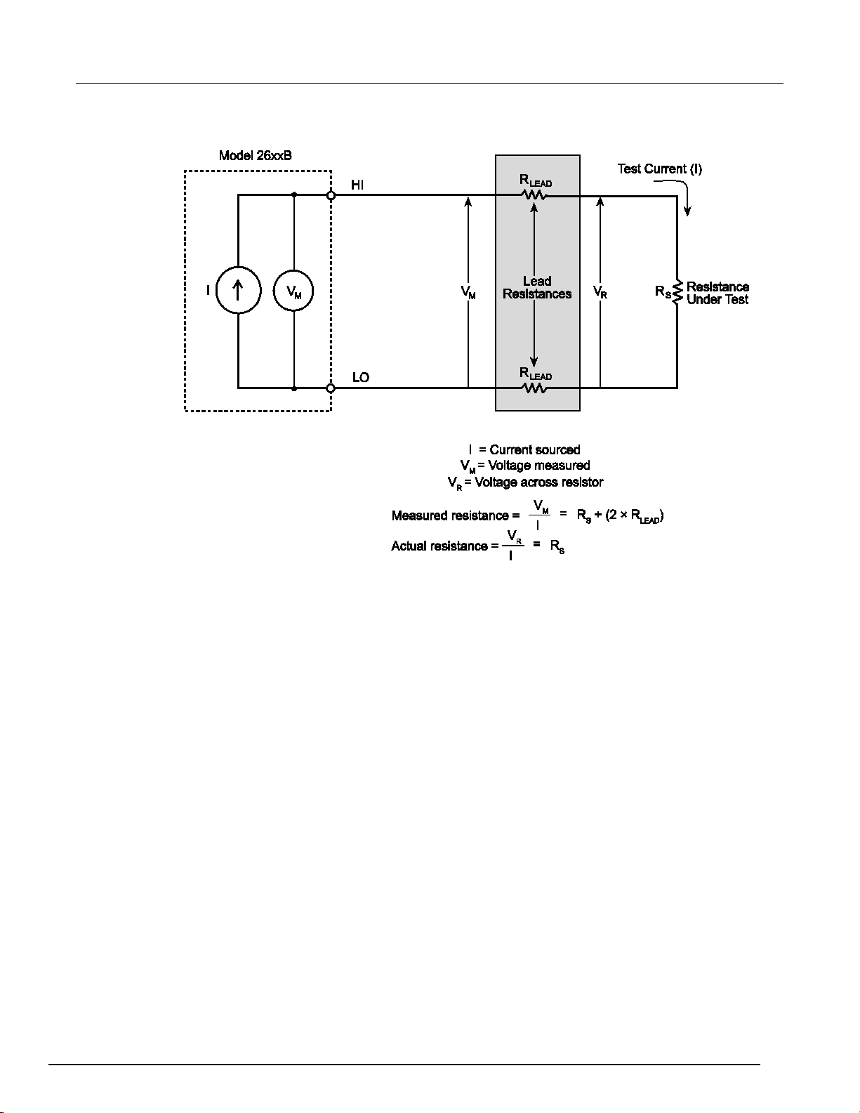
Series 2600B
General operation
System SourceMeter® Instrument Refer en ce Manual Section 2:
Figure 12: 2-wire resistance sensing
2600BS-901-01 Rev. B / May 2013 2-41
Page 66

Section
Reference Manual
2: General operation Series 2600B System SourceMeter® Instrument
The 4-wire sensing method, as shown in the following figure (4-wire resistance sensing), minimizes or
eliminates the effects of lead resistance by measuring the voltage across the resistor under test with
a second set of test leads. Because of the high input impedance of the voltmeter, the current through
the sense leads is negligible, and the measured voltage is essentially the same as the voltage across
the resistor under test.
Figure 13: 4-wire resistance sensing
Power measurements
Power calculations
Power readings are calculated from the measured current and voltage as follows:
Where:
P is the calculated power
V is the measured voltage
I is the measured current
Basic power measurement procedure
If you need to customize the MODE key's standard watt-meter configuration, perform the following
steps to perform power measurements. The following procedure assumes that the Series 2600B is
already connected to the device under test (DUT) as explained in DUT test connections (on page
48).
2-
2-42 2600BS-901-01 Rev. B / May 2013
Page 67

Series 2600B
General operation
System SourceMeter® Instrument Reference M anual Section 2:
Hazardous voltages may be present on the output and guard terminals. To prevent
electrical shock that could cause injury or death, never make or break connections to the
Series 2600B while the output is on. Power off the equipment from the front panel or
disconnect the main power cord from the rear of the Series 2600B before handling cables
connected to the outputs. Putting the equipment into standby does not guarantee the
outputs are not powered if a hardware or software fault occurs.
To perform power measurements from the front panel:
This procedure requires dual-channel instruments (Models 2602B, 2604B, 2612B, 2614B, 2634B,
and 2636B) to be placed in single-channel display mode. For these models, press the DISPLAY key
to select single-channel display mode. See Display mode (on page 2-24
).
1. Set source function and value. Press the SRC key to select the voltage or current source function
as required.
2. Set the output voltage or current to an appropriate value. See Step 1 of Front-panel source-
measure procedure ( on pa ge 2-32) earlier in this section.
3. Press the LIMIT key and set the voltage or current limit high enough for the expected voltage or
current across the DUT to be measured. See Step 2 of Front-panel source-measure procedure
(on page 2-32) earlier in this section.
4. Press the MEAS key as many times as needed to display power.
5. Press the OUTPUT ON/OFF control to turn the output on.
6. View the displayed reading (press the TRIG key if necessary).
7. When finished, press the OUTPUT ON/OFF control again to turn the output off.
Power measurements using the remote interface
The following paragraphs summarize basic power measurement commands using the remote
interface and also give a programming example for a typical power measurement situation.
Remote power reading command
The programming example below illustrates how to obtain a power reading from SMU A:
reading = smua.measure.p()
See Remote source-measure commands (on page 2-34) for more commands necessary to set up
source and measure functions and also Introduction to TSP operation (on page 5-1).
Power measurement programming example
The following programming example illustrates the setup and command sequence for a typical power
measurement procedure with the following parameters:
• Source function: voltage, source autorange, 5 V output
• Current measure function and range: current, autorange
• Current compliance: 50 mA
2600BS-901-01 Rev. B / May 2013 2-43
Page 68

Section
Reference Manual
2: General operation Series 2600B System SourceMeter® Instrument
-- Restore Series 2600B defaults.
smua.reset()
-- Select voltage source function.
smua.source.func = smua.OUTPUT_DCVOLTS
-- Enable source autoranging.
smua.source.autorangev = smua.AUTORANGE_ON
-- Set voltage source to 5 V.
smua.source.levelv = 5
-- Set current limit to 50 mA.
smua.source.limiti = 50e-3
-- Set current range to auto.
smua.measure.autorangei = smua.AUTORANGE_ON
-- Turn on output.
smua.source.output = smua.OUTPUT_ON
-- Get power reading.
print(smua.measure.p())
-- Turn off output.
smua.source.output = smua.OUTPUT_OFF
Contact check measurements
The Models 2604B, 2614B, and 2634B do not perform contact check measurements.
Overview
The contact check function prevents measurements that may be in error due to excessive resistance
in the force or sense leads when making remotely sensed (Kelvin) measurements. Potential sources
for this resistance include poor contact at the device under test (DUT), failing relay contacts on a
switching card, and wires that are too long or thin. To use contact check, the current limit must be at
least 1 mA (this allows enough current to flow when performing the test), and the source-measure
unit (SMU) must not be in High-Z output-off mode.
The contact check function will also detect an open circuit that may occur when a four-point probe is
misplaced or misaligned. This relationship is shown schematically in the figure titled "Contact check
measurements," where R
series resistance of relays and cables.
is the resistance of the mechanical contact at the DUT, and RS is the
C
2-44 2600BS-901-01 Rev. B / May 2013
Page 69

Series 2600B
General operation
flag = smuX.contact.check()
rhi, rlo = smuX.contact.r()
Measure the aggregate contact resistance.
smuX.contact.speed = speed_opt
2
smuX.CONTACT_SLOW
smuX.contact.threshold = rvalue
smu
smua
smua
smub
System SourceMeter® Instrument Reference M anual Section 2:
Figure 14: Contact check measurements
Contact check commands
The following table summarizes the basic contact check commands. For a more complete description
of these commands, refer to the TSP command reference (on page 7-1
). For connection information,
refer to Contact check connections (on page 2-54).
Basic contact check commands
Command* Description
Determine if contact resistance is lower than threshold.
Set speed_opt to one of the following:
0 or smuX.CONTACT_FAST
1 or smuX.CONTACT_MEDIUM
or
Set resistance threshold for the contact check function.
*
X: For Models 2601B, 2611B, and 2635B, this value is
2612B, 2614B, 2634B, and 2636B, this value can be
(SMU Channel A); for Models 2602B, 2604B,
(for SMU Channel A) or
(for SMU Channel B).
Contact check programming example
The following programming example illustrates the setup and command sequence for a typical
contact measurement. These commands set the contact check speed to fast and the threshold to
100 Ω. Then, a contact check measurement against the threshold is made. If it fails, a more accurate
contact check measurement is made, and the test is aborted. Otherwise, the output is turned on, and
the test continues.
2600BS-901-01 Rev. B / May 2013 2-45
Page 70

Section
Reference Manual
2: General operation Series 2600B System SourceMeter® Instrument
-- Restore defaults.
smua.reset()
-- Set speed to fast.
smua.contact.speed = smua.CONTACT_FAST
-- Set threshold to 100 ohms.
smua.contact.threshold = 100
-- Check contacts against threshold.
if not smua.contact.check() then
-- Set speed to slow.
smua.contact.speed = smua.CONTACT_SLOW
-- Get aggregate resistance readings.
rhi, rlo = smua.contact.r()
-- Return contact resistances to the host.
print(rhi, rlo)
-- Terminate execution.
exit()
end
-- Turn output on and continue.
smua.source.output = smua.OUTPUT_ON
Saved setups
You can restore the Series 2600B to one of six nonvolatile memory setup configurations (five user
setups and one factory default), or to a setup stored on an external USB flash drive. As shipped from
the factory, the Series 2600B powers up with the factory default settings, which cannot be
overwritten. The default settings are also in the five user setup locations, but may be overwritten. The
factory default settings are listed in the command descriptions in the TSP command reference (on
page 7-1).
Saving user setups
The setup configuration that is used when the instrument powers up can be changed.
You can save the present Series 2600B setup to internal nonvolatile memory or a USB flash drive.
To save a user setup to nonvolatile memory from the front panel:
1. Configure the Series 2600B to the settings that you want to save.
2. Press the MENU key.
3. Select SETUP and then press the ENTER key.
4. Select the SAVE menu item and then press the ENTER key.
5. Select INTERNAL and then press the ENTER key.
6. Select the user number (1 through 5), and press the ENTER key.
To save a user setup to an external USB flash drive from the front panel:
1. Configure the Series 2600B to the settings that you want to save.
2. Insert the USB flash drive into the USB port on the front panel of the Series 2600B.
3. Press the MENU key.
4. Select SETUP and then press the ENTER key.
5. Select SAVE and then press the ENTER key.
6. Select USB1. The file name setup000.set is displayed.
7. Turn the navigation wheel to change the last three digits of the file name and then press the
ENTER key.
2-46 2600BS-901-01 Rev. B / May 2013
Page 71

Series 2600B
General operation
System SourceMeter® Instrument Reference M anual Section 2:
Recalling a saved setup
You can recall setups from internal nonvolatile memory or a USB flash drive at any time.
To recall a saved setup from the front panel:
1. Press the MENU key to access the main menu.
2. Select SETUP, and then press the ENTER key.
3. Select the RECALL menu item, and then press the ENTER key.
4. Select one of the following:
• INTERNAL
• USB1
INTERNAL only: Do one of the following:
• Select FACTORY to restore factory defaults, then press the ENTER key.
• Select the user number (1 through 5), then press the ENTER key.
USB1 only: Select the appropriate file and then press the ENTER key.
Start-up configuration
You can specify the Series 2600B start-up (power-on) configuration from the front panel. Set the
start-up configuration to a previously stored setup (recalled from internal nonvolatile memory) or reset
to the factory default setup.
To select the power-on setup:
1. Press the MENU key to access the main menu.
2. Select SETUP, and then press the ENTER key.
3. Select POWERON, and then press the ENTER key.
4. Select the configuration to use.
5. Press the ENTER key.
6. Use the EXIT (LOCAL) key to return to the main display.
2600BS-901-01 Rev. B / May 2013 2-47
Saving user setups from a remote interface
Saving and recalling user setups
Use the setup.save() and setup.recall() functions to save and recall user setups.
To save and recall user setups using remote commands:
The following example saves the present setup as setup 1, and then recalls setup 1:
-- Save the present setup to nonvolatile memory.
setup.save(1)
-- Recall the saved user setup from nonvolatile memory.
setup.recall(1)
Restoring the factory default setups
Use one of the reset functions to return the Series 2600B to the original factory defaults. An example
of each type of reset is shown in the following program examples.
®
Restore all factory defaults of all nodes on the TSP-Link
reset()
network:
Page 72

Section
Reference Manual
n
=
0 (*RST/reset() factory defaults)
n
=
1 to 5 (user setups 1-5)
2: General operation Series 2600B System SourceMeter® Instrument
Restore all factory defaults (note that you cannot use *rst in a script):
*rst
Restore all factory defaults:
setup.recall(0)
Restore channel A defaults:
smua.reset()
Reset just the local TSP-Link node:
localnode.reset()
Start-up (power-on) configuration
You can specify the Series 2600B start-up (power-on) configuration. Use the setup.poweron
attribute to select which setup to return to upon power-up. To set the setup.poweron configuration
attribute:
setup.poweron = n -- Select power-on setup.
Where:
DUT test connections
Hazardous voltages may be present on all output and guard terminals. To prevent electrical
shock that could cause injury or death, never make or break connections to the Series
2600B while the instrument is powered on. Turn off the equipment from the front panel or
disconnect the main power cord from the rear of the Series 2600B before handling cables.
Putting the equipment into standby does not guarantee that the outputs are powered off if a
hardware or software fault occurs.
Input/output connectors
The Keithley Instruments Series 2600B System SourceMeter® instrument uses screw terminal
connectors or triaxial connectors for input and output connections to devices under test (DUTs). The
Models 2601B, 2602B, 2604B, 2611B, 2612B, and 2614B use screw terminal connectors; Models
2634B, 2635B, and 2636B use triaxial connectors.
A screw terminal connector can be removed from the rear panel by loosening the two captive
retaining screws and pulling it off the rear panel. Each screw in the terminal connector cable
assembly (used with the SMU connector) can accommodate from 24 AWG (0.2 mm
(2.5 mm
Basic connection sequence:
1. With the output off and the connector uninstalled from the Series 2600B rear panel, make the
2. Reinstall the connector onto the rear panel.
3. If using a screw terminal connector, tighten the two captive screws.
2
) conductors.
wire connections from a connector to the DUT.
2
) to 12 AWG
2-48 2600BS-901-01 Rev. B / May 2013
Page 73

Series 2600B
General operation
System SourceMeter® Instrument Refer en ce Manual Section 2:
Hazardous voltages may be present on the output and guard terminals. To prevent
electrical shock that could cause injury or death, never make or break connections to the
Series 2600B while the output is on. Power off the equipment from the front panel or
disconnect the main power cord from the rear of a System SourceMeter® instrument before
handling cables connected to the outputs. Putting the equipment into standby does not
guarantee the outputs are not powered if a hardware or software fault occurs.
Maximum floating (common mode) voltage for a SMU is 250 V. Exceeding this level could
damage the instrument and create a shock hazard. See Floating a SMU later in this section
for details on floating the SMUs.
The input/output connectors of the System SourceMeter® instrument are rated for
connection to circuits rated Measurement Category I only, with transients rated less than
1500 V peak. Do not connect the Series 2600B terminals to CAT II, CAT III, or CAT IV
circuits. Connections of the input/output connectors to circuits higher than CAT I can cause
damage to the equipment or expose the operator to hazardous voltages.
To prevent electric shock and/or damage to the System SourceMeter® instrument, when
connecting to a source with a greater current capability than the Series 2600B, a usersupplied fuse, rated at no more than 20 A SLO-BLO, should be installed in-line with the
Series 2600B input/output connectors.
2600BS-901-01 Rev. B / May 2013 2-49
Page 74

Section
Reference Manual
2: General operation Series 2600B System SourceMeter® Instrument
Figure 15: Input/output connectors
2-50 2600BS-901-01 Rev. B / May 2013
Page 75

Series 2600B
General operation
System SourceMeter® Instrument Reference M anual Section 2:
Input/output LO and chassis ground
As shown below, SMU input/output LOs are available at the rear panel terminal blocks. Input/output
LOs are not connected between channels and are electrically isolated from chassis ground.
As shown, there is a low-noise chassis ground banana jack that can be used as a common signal
ground point for Input/Output LOs. This low-noise signal ground banana jack is connected to the
chassis through a Frequency Variable Resistor (FVR).
The FVR (in the figure below) is used to isolate the SMUs from high frequencies that may be present
on the chassis of the Series 2600B. As frequencies on the chassis increase, the resistance of the
FVR increases to dampen its effects.
Keep in mind that the chassis should never be used as a ground point for signal connections. High
frequencies present on the chassis of the Series 2600B may result in higher noise. The chassis
should only be used as a safety shield. Use the chassis screw for connections to the chassis of the
Series 2600B. For Models 2634B, 2635B, and 2636B, connect to ground on the ground module not
to the chassis screw.
Figure 16: Models 2602B, 2604B, 2612B, and 2614B input/output LO and chassis ground
terminals (Models 2601B and 2611B similar)
2600BS-901-01 Rev. B / May 2013 2-51
Page 76

Section
Reference Manual
2: General operation Series 2600B System SourceMeter® Instrument
Figure 17: Models 2634B and 2636B input/output and chassis ground terminals (Model 2635B
similar)
Figure 18: Models 2601B/2602B/2604B/2611B/2612B/2614B low-noise chassis ground banana
jack and chassis screw
2-52 2600BS-901-01 Rev. B / May 2013
Page 77

Series 2600B
General operation
3-
89
System SourceMeter® Instrument Reference M anual Section 2:
Figure 19: Model 2634B/2636B (Model 2635B similar)
When connecting to Models 2611B, 2612B, 2614B, 2634B, 2635B, and 2636B SMU outputs
using cables not rated for voltages above 42V, such as the 2600A-ALG-2, you must disable
the high voltage output by using the INTERLOCK function as defined in
). Leaving the high voltage enabled while not properly insulating the external connections
Interlock
(on page
to the instrument poses a shock hazard which could cause serious injury to the user. It is
also recommended that the LO connection terminal not be allowed to float by connecting it
to signal ground or another known signal reference.
2-wire local sensing connections
You can use 2-wire local sensing measurements, shown in the following figure, for the following
source-measure conditions:
• Sourcing and measuring current.
• Sourcing and measuring voltage in high impedance (more than 1 kΩ) test circuits.
When using 2-wire local sensing connections, make sure to properly configure the Series 2600B
Sense mode selection (on page 2-76
Figure 20: Two-wire resistance connections
).
2600BS-901-01 Rev. B / May 2013 2-53
Page 78

Section
Reference Manual
2: General operation Series 2600B System SourceMeter® Instrument
4-wire remote sensing connections
When sourcing and/or measuring voltage in a low-impedance test circuit, there can be errors
associated with lead resistance. Voltage source and measure accuracy are optimized by using 4-wire
remote sense connections. When sourcing voltage, 4-wire remote sensing ensures that the
programmed voltage is delivered to the DUT. When measuring voltage, only the voltage drop across
the DUT is measured.
When sourcing voltage in remote sense, make sure the sense leads are connected to the DUT. If a
sense lead becomes disconnected, an erroneous voltage will be sensed, and the Series 2600B may
increase the output voltage to compensate. For the Models 2601B, 2602B, 2611B, 2612B, 2635B,
and 2636B, you can use contact check to verify that the sense leads are connected. Refer to Contact
check measurements (on page 2-44).
Use 4-wire remote sensing for the following source-measure conditions:
• Sourcing or measuring voltage in low impedance (<1 kΩ) test circuits.
• Enforcing voltage compliance limit directly at the DUT.
When using 4-wire local sensing connections, make sure to properly configure the Series 2600B
Sense mode selection (on page 2-76
).
Figure 21: Four-wire connections (remote sensing)
Contact check connections
The Models 2604B, 2614B, and 2634B do not perform contact check measurements.
The contact check function prevents measurement errors due to excessive resistance in the source
or sense leads. See Contact check measurements (on page 2-44
Contact check requires both source and sense connections. Refer to 4-wire remote sensing
connections (on page 2-54) for connection scheme.
) for operation.
2-54 2600BS-901-01 Rev. B / May 2013
Page 79

Series 2600B
General operation
System SourceMeter® Instrument Reference M anual Section 2:
Multiple SMU connections
Carefully consider and configur e the ap propr i ate outp u t -off state, source, and compliance limits
before connecting the Series 2600B to a device that can deliver energy (for example, other voltage
sources, batteries, capacitors, solar cells, or other Series 2600B instruments). Configure
recommended instrument settings before making connections to the device. Failure to consider the
output-off state, source, and compliance limits may result in damage to the instrument or to the
device under test (DUT).
The following figures show how to use the SMUs of two Series 2600B instruments to test a 3-terminal
device, such as an N-channel JFET (see TSP advanced features (on page 6-53
using multiple Series 2600B instruments). A typical application is for a Series 2600B to source a
range of gate voltages, while the another Series 2600B sources voltage to the drain of the device and
measures current at each gate voltage.
Figure 22: Two SMUs connected to a 3-terminal device (local sensing)
) for information on
2600BS-901-01 Rev. B / May 2013 2-55
Page 80

Section
Reference Manual
2: General operation Series 2600B System SourceMeter® Instrument
Figure 23: Two SMUs (Model 2634B or 2636B) connected to a 3-terminal device (local sensing,
floating)
2-56 2600BS-901-01 Rev. B / May 2013
Page 81

Series 2600B
General operation
System SourceMeter® Instrument Refer en ce Manual Section 2:
The following figure illustrates using three SMUs to test the same 3-terminal device. The third SMU is
connected to the source (S) terminal of the JFET. This allows the source terminal to be biased above
signal LO. Setting this SMU to output 0 V effectively connects the source terminal of the JFET to
signal LO.
Figure 24: Three SMUs connected to a 3-terminal device
2600BS-901-01 Rev. B / May 2013 2-57
Page 82

Section
Reference Manual
2: General operation Series 2600B System SourceMeter® Instrument
Figure 25: Three SMUs (Model 2634B or 2636B) connected to a 3-terminal device (local
sensing, non-floating)
2-58 2600BS-901-01 Rev. B / May 2013
Page 83

Series 2600B
General operation
Source current using parallel SMUs
Maximum Pulsed Signal Levels for Series 2600B:
smuX.trigger.source.limitv = 5
System SourceMeter® Instrument Reference M anual Section 2:
Combining SMU outputs
The following information provides cautions and important considerations that need to be observed
when combining SMU output channels.
Use care when combining SMU channels. Whenever SMU channels are combined, it is best to use
instruments with identical current and voltage envelopes/ranges.
Carefully consider and configur e the ap propr i ate outp u t -off state, source, and compliance limits
before connecting the Series 2600B to a device that can deliver energy (for example, other voltage
sources, batteries, capacitors, solar cells, or other Series 2600B instruments. Configure
recommended instrument settings before making connections to the device. Failure to consider the
output-off state, source, and compliance limits may result in damage to the instrument or to the
device under test (DUT).
Configuration guidelines are presented in the following table. Additional information, including
examples on combining SMU channels, can be found in application notes on the
website (http://www.keithley.com).
Keithley Instruments
SourceMeter® instrument configuration
Guidelines
Model 2601B/2602B/2604B:
20 A with 18 V limit
Model 2611B/2612B/2614B/2634B/2635B/2636B:
20 A with 4.5 V limit
SMU 1 configuration:
Output-off mode:
smuX.source.offmode = smuX.OUTPUT_NORMAL
Output-off function:
smuX.source.offfunc = smuX.OUTPUT_DCVOLTS
Current limit for normal output-off mode (this is the maximum current
that will flow between the two SMUs when the output is off):
smuX.source.offlimiti = 1e-3 (default)
Voltage compliance must be 10% lower than the voltage compliance
of SMU 2. Therefore this SMU will control the maximum voltage
across the DUT. Voltage compliance limit (maximum):
Model 2601B/2602B/2604B:
smuX.trigger.source.limitv = 18
Model 2611B/2612B/2614B/2634B/2635B/2636B:
smuX.trigger.source.limitv = 4.5
SMU 2 configuration:
Output-off mode:
smuX.source.offmode = smuX.OUTPUT_NORMAL
Output-off function:
smuX.source.offfunc = smuX.OUTPUT_DCAMPS
Normal output-off voltage limit:
smuX.source.offlimitv = 20 (default)
Voltage compliance must be 10% higher than the voltage compliance
of SMU 1. Voltage compliance limit (maximum ) :
Model 2601B/2602B/2604B:
smuX.trigger.source.limitv = 20
Model 2611B/2612B/2614B/2634B/2635B/2636B:
2600BS-901-01 Rev. B / May 2013 2-59
Page 84

Section
Reference Manual
Source voltage using series SMUs
Maximum Pulsed Signal Levels for Series 2600B:
smuX.trigger.source.limiti = 0.9
2: General operation Series 2600B System SourceMeter® Instrument
SourceMeter® instrument configuration
Guidelines
Model 2601B/2602B/2604B:
80 V with 1.35 A limit
Model 2611B/2612B/2614B/2634B/2635B/2636B:
400 V with 900 mA limit
SMU 1 configuration:
Output-off mode:
smuX.source.offmode = smuX.OUTPUT_NORMAL
Output-off function:
smuX.source.offfunc = smuX.OUTPUT_DCVOLTS
Normal output-off current limit:
smuX.source.offlimiti = 1e-3 (default)
Current compliance must be 10% higher than the current compliance
of SMU 2. Current compliance limit (maximum):
Model 2601B/2602B/2604B:
smuX.trigger.source.limiti = 1.5
Model 2611B/2612B/2614B/2634B/2635B/2636B:
smuX.trigger.source.limiti = 1
The polarity of SMU 1 is generally the opposite of the desired voltage
polarity across the device. In order to achieve a positive voltage
across the device, program SMU 1 to a negative voltage level. For
example, to output 80 V across the device, program SMU 1 to -40 V
and SMU 2 to +40 V. In order to achieve a negative voltage across the
device, program SMU 1 to a positive voltage level and SMU 2 to a
negative voltage level.
Source polarity changes incur a 100 µs penalty. The number 0 is
considered a positive value. For negative-going pulses with a 0 V bias
level, avoid the time penalty by programming a negative number very
near zero, for example, -1e-30 V.
SMU 2 configuration:
Output-off mode:
smuX.source.offmode = smuX.OUTPUT_NORMAL
Output-off function:
smuX.source.offfunc = smuX.OUTPUT_DCVOLTS
Normal output-off current limit (0.9 mA which is 10% less than the
SMU 1 smuX.source.offlimiti):
smuX.source.offlimiti = 0.9e-3
Current compliance must be 10% lower than the current compliance of
SMU 1.Therefore this SMU will control the maximum current through
the DUT. Current compliance limit (maximum):
Model 2601B/2602B/2604B:
smuX.trigger.source.limiti = 1.35
Model 2611B/2612B/2614B/2634B/2635B/2636B:
2-60 2600BS-901-01 Rev. B / May 2013
Page 85

Series 2600B
General operation
Source voltage with extended current using
Maximum Pulsed Signal Levels for Series 2600B:
smuX.trigger.source.limitv = 5
For all configurations
smuX.OUTPUT_HIGH_Z
System SourceMeter® Instrument Reference M anual Section 2:
SourceMeter® instrument configuration
parallel SMUs
Guidelines
Model 2601B/2602B/2604B:
18 V with 18 A limit
Model 2611B/2612B/2614B/2634B/2635B/2636B:
4.5 V with 18 A limit
SMU 1 configuration:
Output-off mode:
smuX.source.offmode = smuX.OUTPUT_NORMAL
Output-off function:
smuX.source.offfunc = smuX.OUTPUT_DCVOLTS
Normal output-off current limit:
smuX.source.offlimiti = 1e-3 (default)
The current compliance of SMU 1 (V-source) must be 10% greater
than that maximum programmed current of SMU 2 (I-source)
Current compliance limit (maximum):
smuX.trigger.source.limiti = 10
SMU 2 configuration:
Output-off mode:
smuX.source.offmode = smuX.OUTPUT_NORMAL
Output-off function:
smuX.source.offfunc = smuX.OUTPUT_DCAMPS
Normal output-off voltage limit:
smuX.source.offlimitv = 20
The voltage compliance of SMU 2 (I-source) must be 10% greater
than the maximum programmed voltage of SMU 1 (V-source).
Voltage compliance limit (maximum):
Model 2601B/2602B/2604B:
smuX.trigger.source.limitv = 20
Model 2611B/2612B/2614B/2634B/2635B/2636B:
• For comparable rise times, the source range and level of
SMU 1 must match the source range and level of SMU 2
• The programmed current and voltage levels for both SMUs
must fall within the same region of the power envelope.
• Placing two voltage sources in parallel is not recommended
• Placing two current sources in series is not recommended
• Think carefully about the appropriate output-off mode
(smuX.source.offmode) and output-off function
(smuX.source.offfunc) whenever changes are made to the
source function. The alternative is to always use the high
impedance output-off mode (smuX.source.offmode =
).
Combining channels in series to output higher voltage
Channels in series can cause hazardous voltage (>30 V RMS, 42 V peak) to be present and
accessible at the Series 2600B output connector. A safety shield must be used whenever
hazardous voltages will be present in the test circuit. To prevent electrical shock that could
cause injury or death, never use the Series 2600B in a test circuit that may contain
2600BS-901-01 Rev. B / May 2013 2-61
hazardous voltages without a properly installed and configured safety shield.
Page 86

Section
Reference Manual
2: General operation Series 2600B System SourceMeter® Instrument
Higher pulse voltage can be output by connecting two (and only two) Series 2600B instrument
channels in series. When combining two SMU channels, make sure both SMUs have the same model
number.
The following figure illustrates a Model 2612B configured with the two channels connected in series to
output up to 400 V (200 V per channel).
Whenever hazardous voltage (>30 V RMS, 42 V peak) will be output, a safety shield must completely
surround the DUT test circuit. When using a metal safety shield, it must be connected to a known
protective earth (safety ground) and chassis ground.
Figure 26: Stacking channels for higher voltage
(1) Model 2612B Ch A: SMU maximum pulse voltage: +200 V
(2) Model 2612B Ch B: SMU maximum pulse voltage: -200 V
(3) Series SMU maximum pulse voltage (as shown): 400 V
For further information, visit the Keithley Instruments website
(http://www.keithley.com) for application
notes on combining SMU channels.
Combining channels in parallel to output higher current
Higher pulse current can be output by connecting two (and only two) Series 2600B instrument
channels in parallel. When combining two SMU channels, make sure both SMUs have the same
model number.
2-62 2600BS-901-01 Rev. B / May 2013
Page 87

Series 2600B
General operation
System SourceMeter® Instrument Reference M anual Section 2:
The figure below illustrates the connection scheme of two Model 2602B channels connected in
parallel. Two Model 2602B channels can output up to 20 A at 36 V (see Combining SMU outputs (on
page 2-59)). The current delivered to the DUT is the sum of currents output by SMU channels (IT).
Combining the two Series 2600B instrument channels expands the power envelope. For further
information, visit the Keithley Instruments website
(http://www.keithley.com) for application notes on
combining two Series 2600B instrument channels.
Figure 27: Connecting channels in parallel for higher current
I1 Single SMU maximum pulse current: 10 A
Single SMU maximum pulse current: 10 A
I
2
Paralleled SMU channels maximum pulse current (as shown): 20 A
I
T
Guarding and shielding
You can optimize source-measure performance and safety with the effective use of guarding and
shielding (noise and safety shields).
Safety shield
A safety shield must be used whenever hazardous voltages (>30 V RMS, 42 V peak) will be
present in the test circuit. To prevent electrical shock that could cause injury or death,
never use the Series 2600B in a test circuit that may contain hazardous voltages without a
properly installed and configured safety shield.
The safety shield can be metallic or nonconductive, and must completely surround the DUT test
circuit. A metal safety shield must be connected to a known protective earth (safety ground). See Test
fixture (on page 2-72) for important safety information on the use of a metal or a nonconductive
enclosure.
2600BS-901-01 Rev. B / May 2013 2-63
Page 88

Section
Reference Manual
2: General operation Series 2600B System SourceMeter® Instrument
Safety shielding and hazardous voltages
Model 2601B/2602B/2604B: The maximum output voltage for a Model 2601B/2602B/2604B channel
is 40 V, which is considered a nonhazardous level. However, using two Model 2601B/2602B/2604B
voltage sources in a series configuration or floating a SMU can cause test circuit voltage to exceed
42 V. For example, the source-measure units (SMUs) of two Model 2601B/2602B/2604B instruments
can be connected in series to apply 80 V to a device under test (DUT) (see the following figure). See
TSP advanced features (on page 6-53
) for information on using multiple System SourceMeter®
instrument instruments.
Use #18 AWG wire or larger for connections to protective earth (safety ground) and chassis.
Figure 28: Safety shield for hazardous voltage combining two Model 2601B/2602B/2604B
channels
2-64 2600BS-901-01 Rev. B / May 2013
Page 89
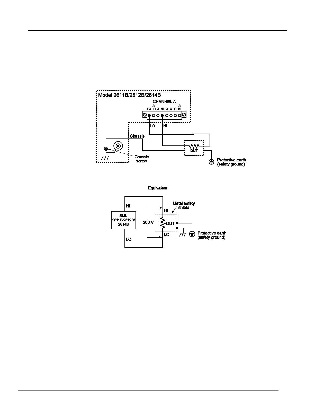
Series 2600B
General operation
System SourceMeter® Instrument Refer en ce Manual Section 2:
Model 2611B/2612B/2614B/2634B/2635B/2636B:
The maximum output voltage for a Model
2611B/2612B/2614B/ 263 4 B/26 35 B/2 636 B cha nne l is 220 V, which is considered hazardous and
requires a safety shield. The following figures illustrate test connections for these models.
Use #18 AWG wire or larger for connections to protective earth (safety ground) and chassis.
Figure 29: Model 2611B/2612B/2614B safety shield for hazardous voltage test circuit
connections
2600BS-901-01 Rev. B / May 2013 2-65
Page 90

Section
Reference Manual
2: General operation Series 2600B System SourceMeter® Instrument
Figure 30: Model 2634B/2635B/2636B safety shield for hazardous voltage test circuit
connections
Guarding
A driven guard is always enabled and provides a buffered voltage that is at the same level as the
input/output HI voltage. The purpose of guarding is to eliminate the effects of leakage current (and
capacitance) that can exist between HI and LO. Without guarding, leakage and capacitance in the
external high-impedance test circuit could be high enough to adversely effect the performance of the
Series 2600B.
Guarding (shown below) should be used when test circuit impedance is >1 GΩ.
2-66 2600BS-901-01 Rev. B / May 2013
Page 91

Series 2600B
General operation
System SourceMeter® Instrument Reference M anual Section 2:
See Guard (on page 4-23) for details on the principles of guarding.
Figure 31: Models 2602B, 2604B, 2612B,and 2614B high-impedance guarding
2600BS-901-01 Rev. B / May 2013 2-67
Page 92

Section
Reference Manual
2: General operation Series 2600B System SourceMeter® Instrument
Figure 32: Models 2634B and 2636B high-impedance guarding (floating) (Model 2635B is
similar)
2-68 2600BS-901-01 Rev. B / May 2013
Page 93

Series 2600B
General operation
System SourceMeter® Instrument Reference M anual Section 2:
Figure 33: Model 2634B and 2636B high-impedance guarding (non-floating) (Model 2635B is
similar)
2600BS-901-01 Rev. B / May 2013 2-69
Page 94

Section
Reference Manual
2: General operation Series 2600B System SourceMeter® Instrument
Noise shield
Use a noise shield (see following figure) to prevent unwanted signals from being introduced into the
test circuit. Low-level signals may benefit from effective shielding. The metal noise shield surrounds
the test circuit and should be connected to LO, as shown.
Figure 34: Models 2602B, 2604B, 2612B, and 2614B noise shield
Figure 35: Models 2634B and 2636B noise shield (floating) (Model 2635B similar)
2-70 2600BS-901-01 Rev. B / May 2013
Page 95

Series 2600B
General operation
System SourceMeter® Instrument Reference M anual Section 2:
Figure 36: Models 2634B and 2636B noise shield (non-floating) (Model 2635B similar)
2600BS-901-01 Rev. B / May 2013 2-71
Using shielding and guarding together
The following figures show connections for a test system that uses a noise shield, a safety shield, and
guarding. The guard shields are connected to the driven guard (labeled G or GUARD, depending on
your model) of the SMU. The noise shield is connected to LO. The safety shield is connected to the
chassis and to protective earth (safety ground).
Connect the enclosure of all metal test fixtures to protective earth (safety ground). See your
specific test fixture for information. Nonconductive test fixtures must be rated to double the
maximum capability of the test equipment in the system.
Page 96

Section
Reference Manual
2: General operation Series 2600B System SourceMeter® Instrument
Figure 37: Connections for noise shield, safety shield, and guarding
Test fixture
A test fixture can be used to house a device or test circuit. The test fixture can be a metal or
nonconductive enclosure, and is typically equipped with a lid. When properly used, the output of the
Series 2600B will turn off when the lid of the test fixture is opened. The test circuit is mounted inside
the test fixture. When hazardous voltages (>30 V RMS, 42 V peak) will be present, the test fixture
must meet the following safety requirements:
To provide protection from shock hazards, an enclosure should be provided that surrounds
all live parts.
Nonconductive enclosures must be constructed of materials that are suitably rated for
flammability and the voltage and temperature requirements of the test circuit. Connect the
enclosure of all metal test fixtures to protective earth (safety ground) (see your specific test
fixture for information). Nonconductive test fixtures must be rated to double the maximum
capability of the test equipment in the system.
For metallic enclosures, the test fixture chassis must be properly connected to protective
earth (safety ground). A grounding wire (#16 AWG or larger) must be attached securely to
the test fixture at a screw terminal designed for safety grounding. The other end of the
ground wire must be attached to a known protective earth (safety ground).
2-72 2600BS-901-01 Rev. B / May 2013
Page 97

Series 2600B
General operation
System SourceMeter® Instrument Refer en ce Manual Section 2:
Construction material: A metal test fixture must be connected to a known protective earth (safety
ground) as described in the above WARNING. A nonconductive test fixture must be constructed of
materials that are suitable for flammability, voltage, and temperature conditions that may exist in the
test circuit. The construction requirements for a nonconductive enclosure are also described in the
WARNING above.
Test circuit isolation: With the lid closed, the test fixture must completely surround the test circuit. A
metal test fixture must be electrically isolated from the test circuit. Input/output connectors mounted
on a metal test fixture must be isolated from the test fixture. Internally, Teflon standoffs are typically
used to insulate the internal printed circuit board or guard plate for the test circuit from a metal test
fixture.
Interlock switch: The test fixture must have a normally-open interlock switch. The interlock switch
must be installed so that when the lid of the test fixture is opened, the switch will open, and when the
lid is closed, the switch will close.
The Series 2600B digital I/O port provides an output enable line or an interlock line (dependent on the
model number). When properly used with a test fixture, the output of the Series 2600B will turn off
when the lid of the test fixture is opened. The output enable (OE) is found on Models
2601B/2602B/2604B whi le the Mode ls 2611B/2612B/2614B/2634B/2635B/2636B have an interlock.
The digital I/O port of the Model 2601B/2602B/2604B is not suitable for control of safety
circuits and should not be used to control a safety interlock. The interlock pin on the digital
I/O port for the Model 2611B/2612B/2614B/2634B/2635B/2636B can be used to control a
safety interlock.
See the topic titled Digital I/O (on page 3-83) for information on the digital I/O port.
Floating a SMU
Using an external source in the test system may require that a Series 2600B source-measure unit
(SMU) float off chassis earth ground. An example of such a test system is shown below, which
includes an external voltage source. Notice that output low of the external voltage source is
connected to chassis earth ground.
For the test circuit shown below, the Series 2600B must float off chassis earth ground. As shown, LO
of the Series 2600B is floating +10 V above chassis earth ground. If LO of the Series 2600B was
instead connected to chassis ground, the external voltage source would be shorted to the chassis
ground.
2600BS-901-01 Rev. B / May 2013 2-73
Page 98

Section
Reference Manual
2: General operation Series 2600B System SourceMeter® Instrument
Figure 38: Floating the Series 2600B schematic
The Series 2600B connections for the floating configuration are shown below. In order to float the
SMU, input/output LO must be isolated from chassis ground. This is accomplished by not connecting
input/output LO to chassis ground.
Figure 39: Model 2601B/2602B/2604B/2611B/2612B/2614B SMU connections
2-74 2600BS-901-01 Rev. B / May 2013
Page 99

Series 2600B
General operation
2-63
System SourceMeter® Instrument Reference M anual Section 2:
Figure 40: Models 2634B and 2636B SMU connections (Model 2635B similar)
The external voltage source can be a SMU of a second Series 2600B instrument or other instrument.
Keep in mind that if the combined outputs of the sources exceeds 42 V, then a safety shield will be
required for the DUT (see the following WARNINGS).
The maximum floating (common mode) voltage for a SMU is ±250 V. Exceeding this level may
cause damage to the instrument and create a shock hazard.
Using an external source to float a SMU could create a shock hazard in the test circuit. A
shock hazard exists whenever >42 V peak is present in the test circuit. Appropriately rated
cables or insulators must be provided for all connections to prevent access to live parts.
When >42 V is present, the test circuit must be insulated for the voltage used or surrounded
by a metal safety shield that is connected to a known protective earth (safety ground) and
chassis ground (see
Safety shield
DUT connection settings
Make sure to properly configure the Series 2600B sense mode for the specific DUT test connection
scheme. Use care to configure the output-off state to supplement safe operation of your test setup.
(on page
)).
2600BS-901-01 Rev. B / May 2013 2-75
Page 100
Section
Reference Manual
smuX.source.output = smuX.OUTPUT_OFF
Turns off the source-mea sure unit
(SMU) output.
smuX.sense = smuX.SENSE_LOCAL
Select local (2-wire) sense.
smuX.sense = smuX.SENSE_LOCAL
Select remote (4-wire) sense.
Channel B).
2: General operation Series 2600B System SourceMeter® Instrument
Sense mode selection
The sense mode can be set to use 2-wire local sensing connections (on page 2-53) or 4-wire remote
sensing connections (on page 2-54).
The default sense setting is 2-wire local.
Front panel sense mode selection
To check or change the sense mode from the front panel:
1. Press the CONFIG key.
2. Press the SRC or MEAS key. You can access and set the Series 2600B sense mode from either
the V-SOURCE or the V-MEAS menu items.
3. If you pressed the SRC key: select V-SOURCE > SENSE-MODE, and then press the ENTER key
or the navigation wheel .
If you pressed the MEAS key: select V-MEAS > SENSE-MODE, and then press the ENTER key
or the navigation wheel .
4. Select 2-WIRE or 4-WIRE as needed, and then press the ENTER key or the navigation wheel .
Selecting the sense from the remote interface
To select the remote sense from the remote interface:
Set the smuX.sense attribute to control the sense state by remote. The programming example below
illustrates how to configure the Series 2600B for 4-wire remote sensing:
smua.sense = smua.SENSE_REMOTE
The following table summarizes the commands to select the sense mode. See Remote source-
measure commands (on page 2-34) and TSP command reference (on page 7-1) for details on using
these commands.
Commands to select sense mode
Command* Description
* smuX: For Models 2601B, 2611B, and 2635B, this value is smua (SMU Channel A); for Models 2602B,
2604B, 2612B, 2614B, 2634B, and 2636B, this value can be smua (for SMU Channel A) or smub (for SMU
2-76 2600BS-901-01 Rev. B / May 2013
 Loading...