

Page 1
INSTRUCTION MANUAL
Model 244
High Voltage Supply
(and Model 2441 Overload Protection Option)
@COPYRIGHT 1976, KEITHLEY INSTRUMENTS, INC.
FOURTH PRINTING, DEC. 1977, CLEVELAND, OHIO, U.S.A.
Page 2

Page 3
MODEL 244
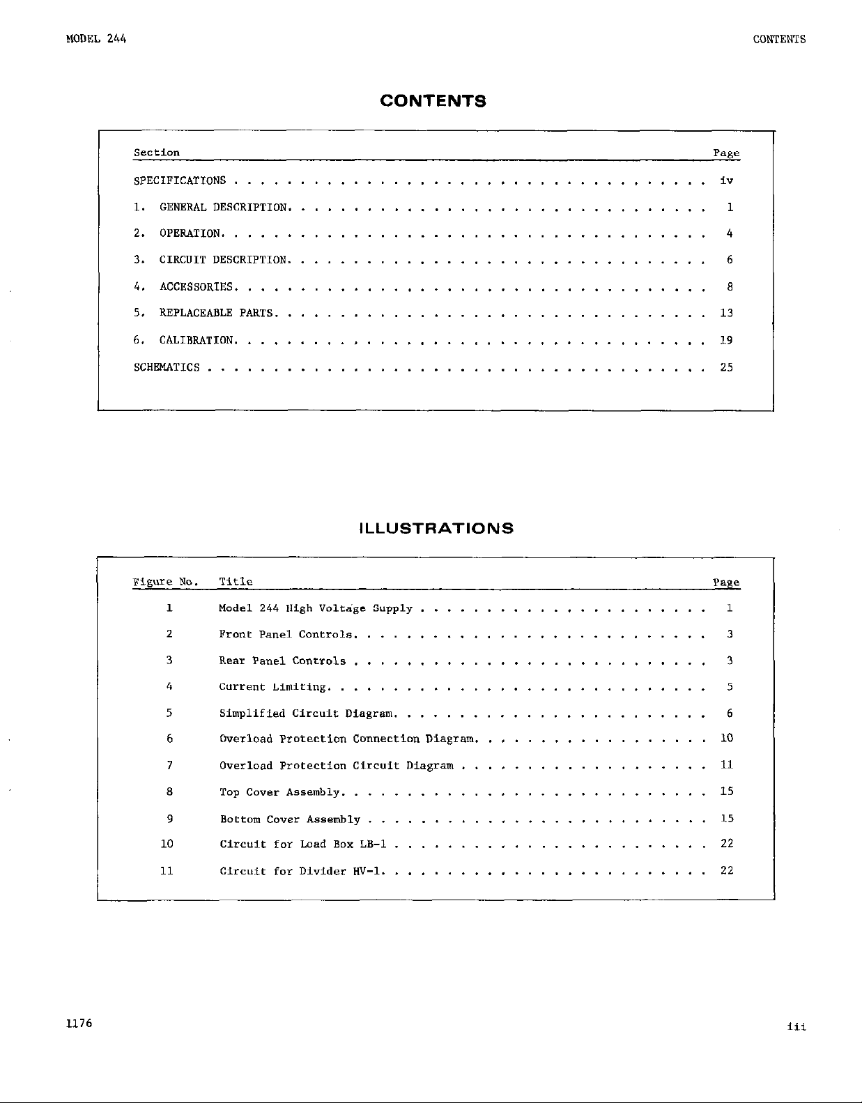
CONTENTS
CONTENTS
SWtiO”
SPECIFIC.4TIONS
....................................
1. GENERAL DESCRIPTION.
2.
OPERATION.
....................................
3. CIRCUIT DESCRIPTION.
4. ACCESSORIES
5. REPLACEABLE PARTS.
6. CALIBRATION
SCHEMATICS
....................................
................................
....................................
......................................
...............................
...............................
ILLUSTRATIONS
Page
iv
1
4
6
8
13
19
25
Figure NO.
1
2 FrOnL Panel Controls.
Title
Model 244 High Volt+ Supply
..........................
3 Rear Panel Controls ...........................
4 current Limiting. ............................
5 Simplified Circuit Diagram.
6
7
8 Top Cover Assembly.
9
10
11
Overload Protection Cmmectio,, Diagram.
Overload Protection Circuit Diagram
...........................
Bottom cover Assembly
..........................
Circuit for Laad BDX LB-1
Circuit for Divider ""-1.
......................
.......................
...................
........................
........................
Page
1
3
3
5
6
................. 10
11
15
15
22
22
1176
Page 4
SI?ECIFICATIONS
MODEL 244 HIGH VOLTAGE SUPPLY
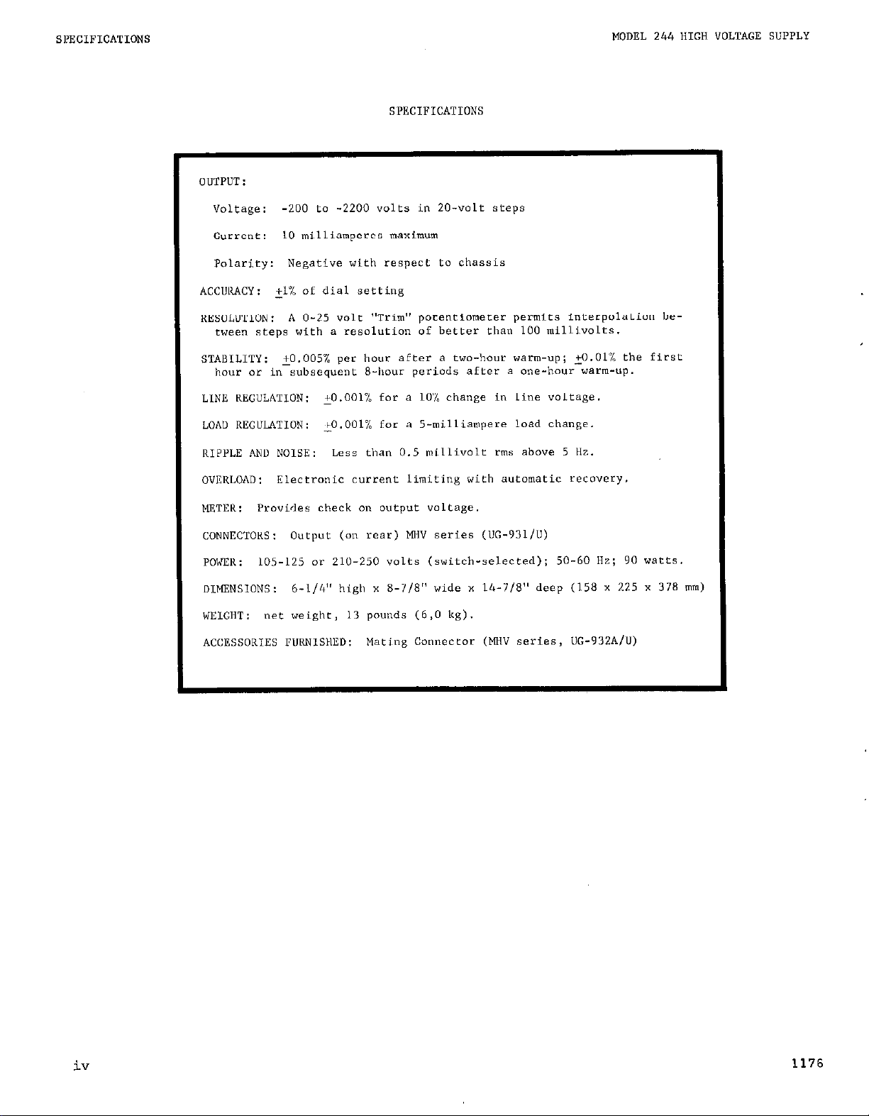
SPECIFICATIONS
OUTPUT :
Voltage:
-200 to -2200 volts in ZO-volt steps
current: 10 milliamperes maximum
Polarity: Negative with respect Lo chassis
ACCWACY: il% of dial setting
RESOLUTION: A O-25 volt "Trim" porentiameter permits interpolation be-
tween steps with a resolution of better than 100 millivalts.
STABILITY: ~0.005% per hour after a two-hour warm-up; +o.Ol% the first
hour or in subsequent S-hour periods after a one-hour warm-up.
LINE KECULATION: +O.OOl% for a 10% change in line voltage.
LOh" REGULATION: ,O.OOl% for a 5-milliampere load change.
RIPPLE AN" NOISE: Less than 0.5 milli"olt rms above 5 Hz.
OVERLOAD: Electronic current limiting with automatic recovery.
METER:
Provides check on OUtpUt voltage.
CONNECTOKS: Output (on rear) MHV series (UC-931/U)
POWER :
105-125 or 210.250 volts (switch-selected); 50-60 Hz; 90 watts.
OIMENSlONS: b-114" high x S-718" wide x l&7/8" deep (158 x 225 x 378 mm)
WEIGHT: net weight, 13 pounds (6,O kg).
ACCESSORIES FURNISMED: Mating Connector (MHV series, UC-932A/U)
iv
1176
Page 5
MODEL 244 HIGH VOLTAGE SUPPLY
GENERAL DESCRIPTlON
SECTION I.
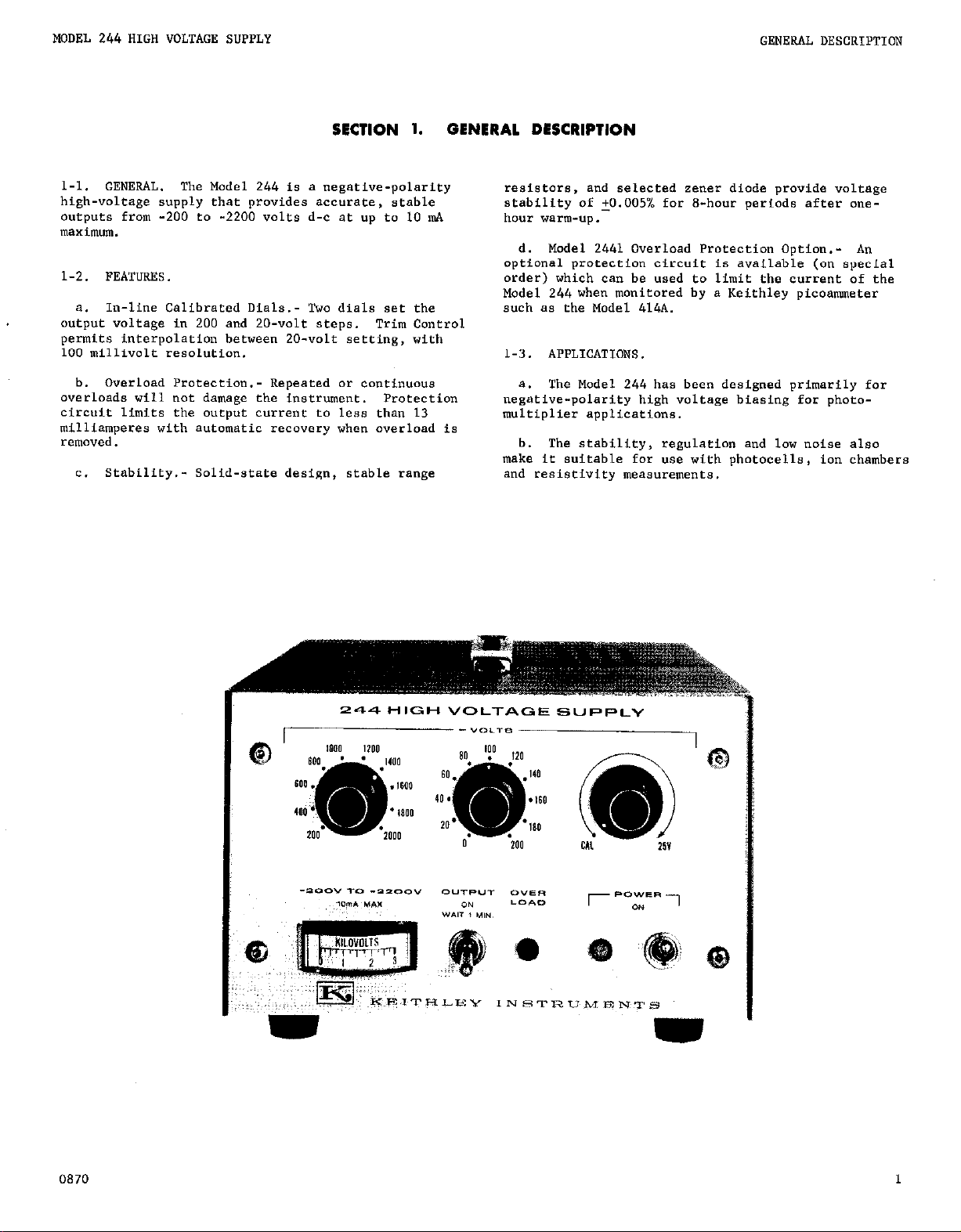
l-l.
GENERAL.
high-voltage supply that provides accurate, stable
outpote from -200 to -2200 volts d-c at up to 10 ,,$.
"l~Xi"l"Ul.
1-2. FEATURES.
a. In-line Calibrated Dials.- Two dials set the
output voltage in 200 and ZO-volt steps. Trim Control
permits interpolation between ZO-volt setting, with
100 millivolt resolution.
b. Overload Protection.- Repeated or continuous
overloads will not damage the instr,m,ent.
circuit limits the oucput current to less than 13
milliamperes with automatic recovery when overload is
removed.
c. Stability.- Solid-state design, stable range
The Model 244 is a negative-polarity
Protection
GENERAL DESCRIPTION
resistors, and selected zener diode provide voltage
stability of +0.005% for B-hour periods after onehour warm-up.
d. Model 2441 Overload Protection Option.- A,,
optional protection circuit is available (on special
order) which can be used to limit the current of the
Model 244 when monitored by e Keithley picoammeter
such es the Model 414A.
1-3. APPLICATIONS.
a. The Model 244 has bee,, designed primarily for
negative-polarity high voltage biasing for photomultiplier applications.
b. The stability, regulation and low noise also
make it suitable for use with photocells, ion chambers
and resietiviey measurements.
0870
1
Page 6
GENERAL DESCRIPTION
MODEL 244 HIGH VOLTAGE SUPPLY
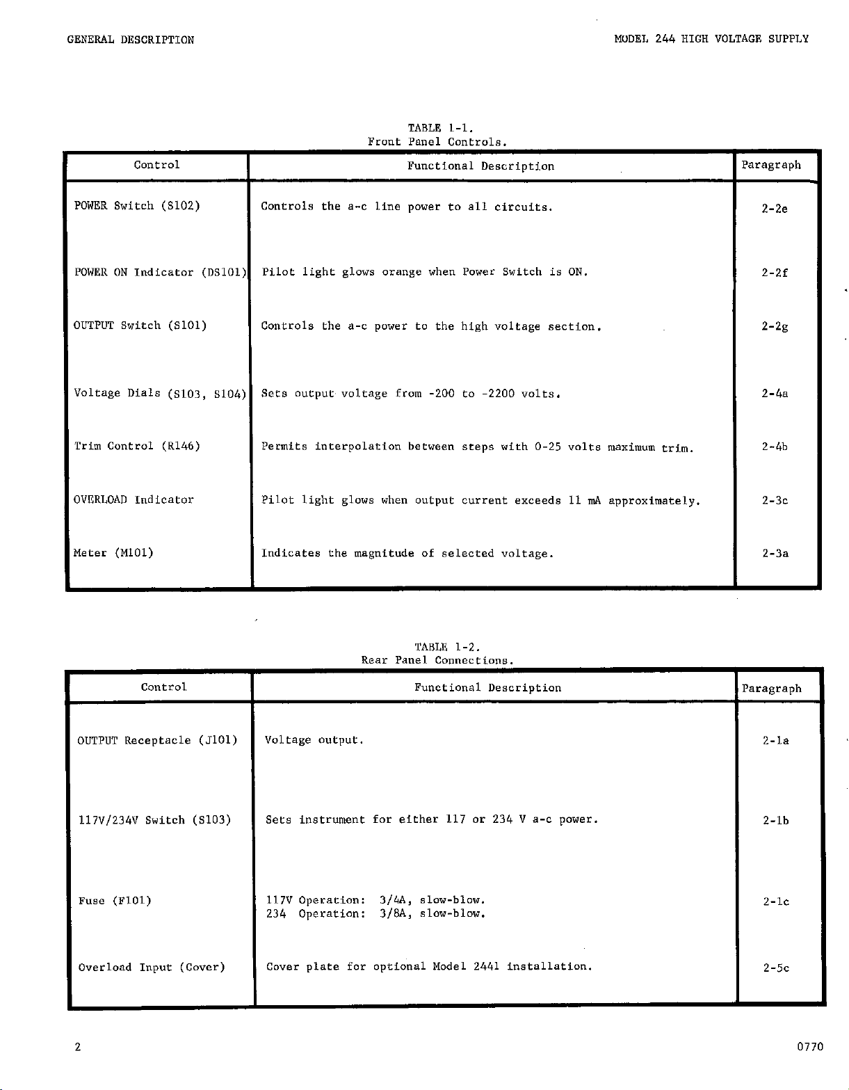
TABLE 1-l.
Front Panel Controls.
COntrOl
OWER Switch (S102)
Controls the a-c line power to all circuits.
Functional Description
OWER ON indicator (mlol) Pilot light glows orange when Power Switch is ON.
UTPUT Switch (5101)
oltwe Dials (s103, s104)
rim Control (R146)
Controls the a-c power to the high voltage section. 2-2g
sets oueput voltage from -200 to -2ml volts.
Permits interpolation between steps with O-25 volts maximum trim.
VBRLOAD Indicator Pilot light glows when output current exceeds 11 I&. approximately.
,eter (MlOl)
Indicates the magnitude of selected voltage.
Paragraph
2-2e
z-2f
2-b
2-a
2-3~
2-3a
Control
OUTPUT Receptacle
117V/234V
Switch (5103)
(5101)
Fuse (FlOl)
Overload Input (Cover)
2
Rear Panel
TABLE 1-2.
Connections.
Functional Description
VOl tage o"tp"t
Sets instrument far either 117 or 234 " a-c power.
117" operation: 3/4A, slow-blow.
234
Operatim: 3/&I, slow-blow.
Cover plate for optional Model 2441 installation.
Paragraph
2-la
Z-lb
2-k
2-k
0770
Page 7
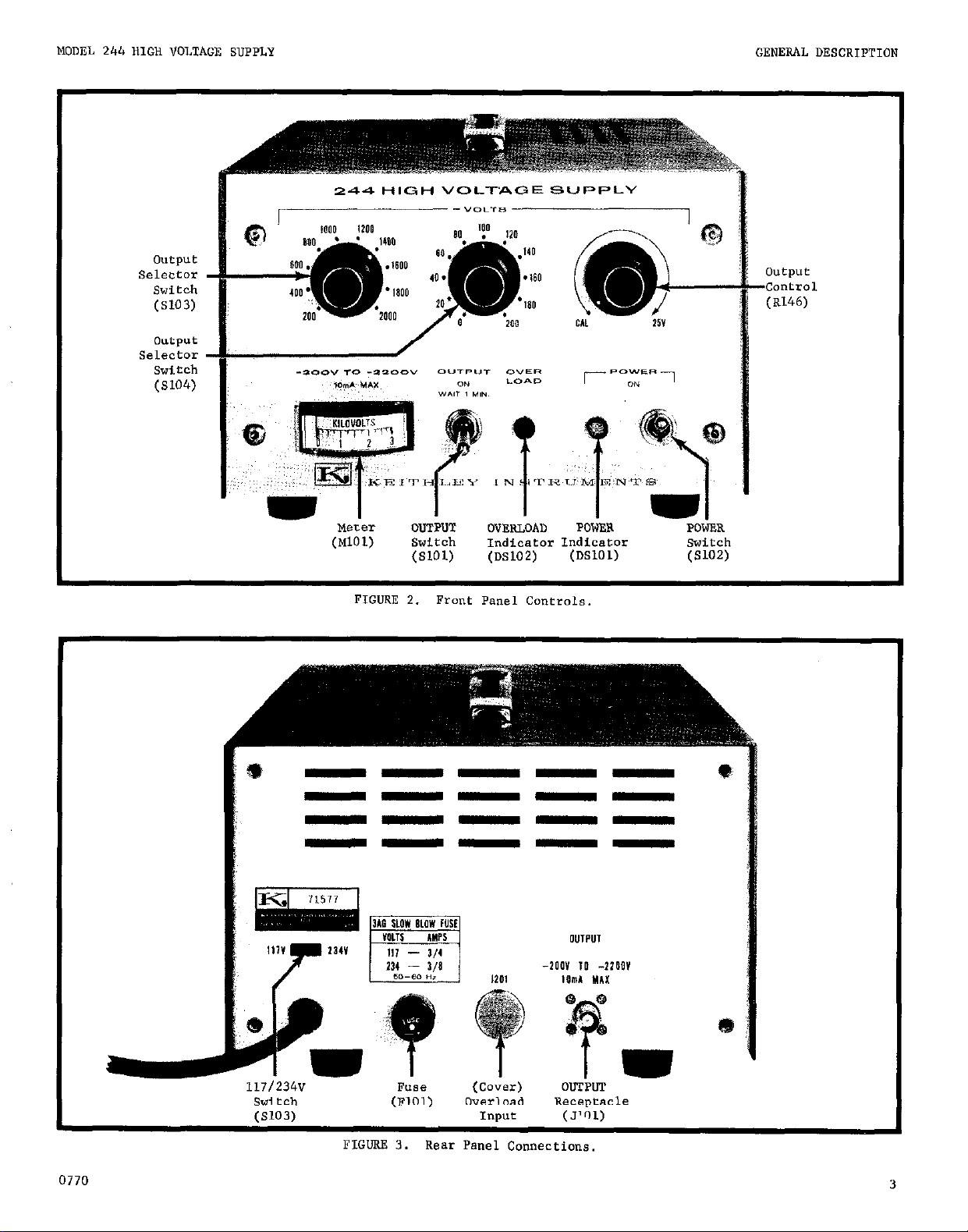
0”tpllt
Selector
Switch
(SlO3)
output
Selector
switch
(X04)
(MlOl)
FIGURE 2. Front Panel Controls.
Switch indicator Indicator
(SlOl) (DS102)
(OSlOl)
Switch
(5102)
0770
117/234V
Switch
(5103)
F"LTC5
(FlOl)
z.rnrmm I) "_^_ n--.7 "~~~-.-_,~
(COWS)
Overload
Input
Receptacle
OUTPUT
(J")l)
3
Page 8
OPERATION
MODEL 244 HIGH VOLTAGE SUPPLY
SECTION 2.
2-1. CONNECTIONS.
a. Output Receptacle.- A rear panel mounted MHV
teflon-insulated receptacle provides connection to
the load circuit. The outer shell of the receptacle
is connected to chassis.
b. Coaxial Cables.- Use coaxial cables which are
rated for greater than 2200 volts for safe operation.
Coaxial cables provide best noise immunity for critical meaeurements.
C. Earth Ground.- For maximum operator safety use
the 3-wire power cord with third wire solidly connected to earth ground.
PRELIMINARY PROCEDURES.
2-2.
a. The instrument is shipped in operating condition
+ith all components installed for immediate use.
Set the 117-234 volt switch for operating line
b.
voltage.
C. Check the fuse for proper type and rating.
d. Provide adequate ventilation for the instrument.
Air flow should be maintained along the top and bottom
surfaces.
OPERATION
OPERATING CHECK-OUT.
2-3.
a. Meter Indication.- When the OUTPUT Switch is ON
the meter should indicate the dialed voltage.
b. Output Voltage.- Connect an accurate voltmeter
such as Keithley Model 153 to the output to verify
the power supply voltage accuracy. The Trim Control
should be set to CAL position.
output for dial settings of 200,,,500, and 1000 volts.
Accuracy should be 21% of dial setting.
c. Current Limit.- (Refer also to paragraph 2-5
for a more complete discussion of the overload current
operation.)
1. Connect an accurate ammeter such as a Keithley Model 153 in series with an adjustable resistance decade box.
Model 244 at -200 volts with the OUTPUT Switch
"OFF".
decade box set at 20 kilahms. The ammeter should
indicate 10 mA when the OUTPUT Switch is placed
nON"
Decrease the resistance load until the OVERLOAD Indicator is lighted.
between 11 mA and 12 n!A.
Apply the -200 volt output to the resistance
.
The OVERLOAD Indicator should not be lighted.
Set the dialed voltage on the
The annneter should indicate
measure the Model 244
NOTE
If air flow is constricted the internal
temperature will rise above normal design
limits causing degradation of critical
components.
e. Set the front panel controls as follows:
POWER Switch
Voltage Dials
OUTPUT Switch
f. Connect the line cord and set the POWER
Switch to ON. (The POWER indicator should
be lighted.)
NOTE
The meter should indicate 0 KILOVOLTS.
g. After a preliminary one minute warmup period,
p&ace the OUTPUT Switch to ON position. Allow another
warmup period (30 minutes) for the high voltage sec-
tion to stabilize.
imately one minor division or 200 volts.
The meter should indicate approx-
Off
2-o-o
Off
NOTE
Resistor load power dissipation is approx-
imately 2.2 Watts.
2. Connect an ammeter and 50 kilohm resistive
load to the output of the Model 244. Set the dialed voltage an the Model 244 at -200 volts with the
OUTPUT Switch "OFF".
"ON" position. Reduce the load to zero ohms (short
circuit) and measure the output current. The
ammeter should indicate less than 14 milliamperes
with the Model 244 OVERLOAD Indicator lighted.
SETTING OUTPUT VOLTAGE. The setting of the
2-4.
Voltage Dials and Trim Control determines the magni-
tude of the output.
a. The two Voltage Diala set the output from -200
to -2200 volts d-c in calibrated 200 and 20-volt
steps. With the Trim Control in CAL position the
output is set by the Voltage Dials within specified
kXC"K%Y.
b. The Trim Control interpolates between 20-volt
settings with 100 millivolt resolution. The Trim
Control range is 0 to 25 volts.
Place the OUTPUT Switch to
4
0770
Page 9
MODEL 244 HIGH VOLTAGE SUPPLY
OPERATION
2-5. OVERLOAD PROTECTION.
a. The Model 244 has an overload current limiting
circuit which limits the output short-circuit current
to a maximum 14 milliamperes. The circuit is adjusted
so that the OVEKLOAD Indicator will be lighted when
the output current exceeds 11 milliamperes. When the
overload is removed the Model 244 will automatically
reset to normal operation and the OVERLOAD Indicator
will turn off.
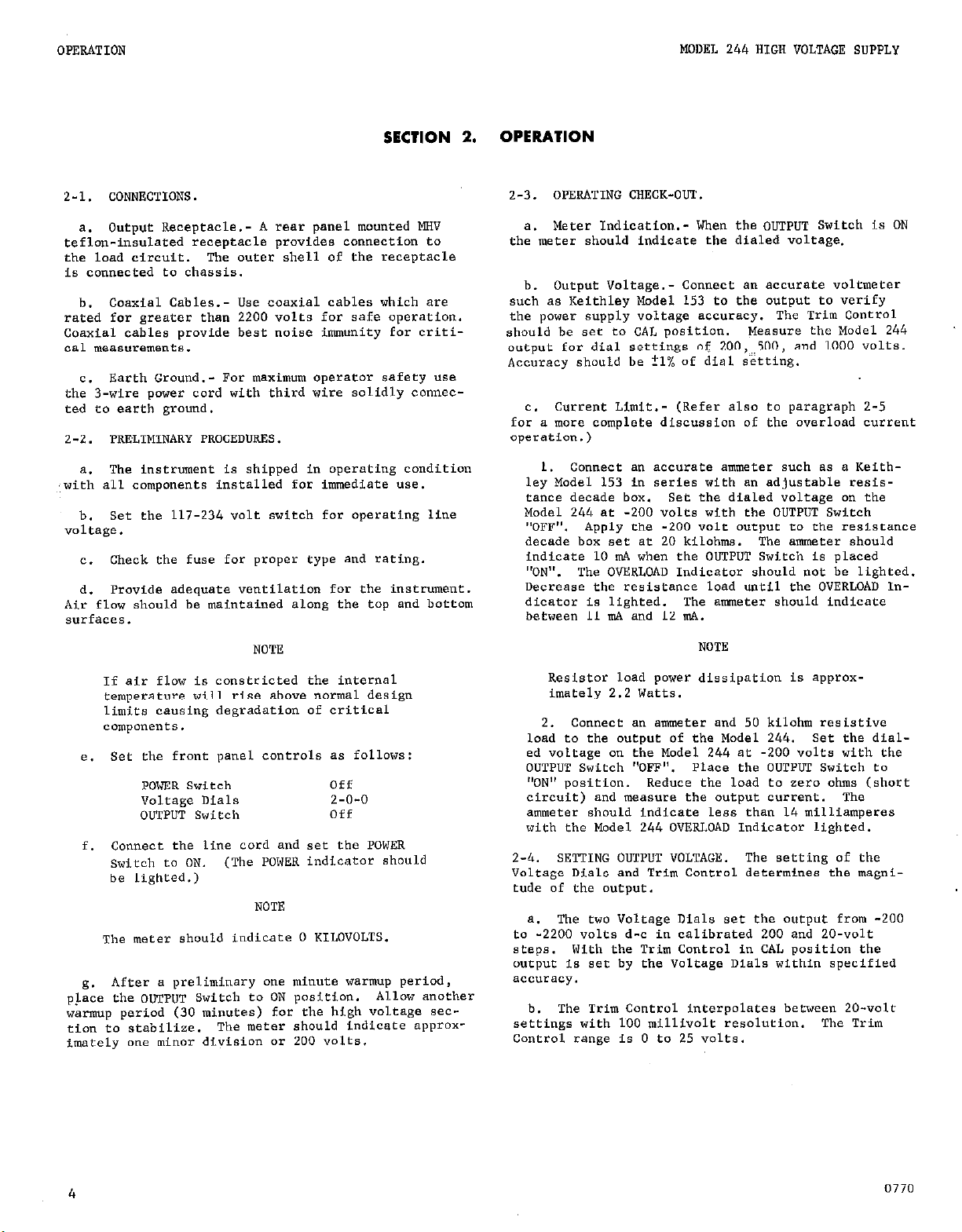
b. Current Limiting Characteristic.- The Model 244
current limiting is shown graphically by the typical
V-I characteristic curves in Figure 4. The OVERLOAD
Indicator is factory-adjusted to turn on at approxi-
mately 11 milliamperes. However the output voltage
remains constant for current exceeding 11 milliamperes
as shown.
The current limiting occurs typically from
11.3 to 12.2 milliamperes depending on the dialed
voltage.
c. Model 2441 Overload Protection Option.- An
optional protection circuit is available which can
bz used to limit the current of the Model 244 when
w>nitored by a Keithley picoammeter such as the
I!zrdel 414A. Consult your Keithley representative or
t:,e Sales Service Department for further information
regarding the Model 2441 Option.
2-6.
CAPACITIVE La4ix.
a. When a capacitive load is connected to the output, Model 244 will deliver a charging current up to
14 milliamperes maximum until the dialed voltage is
developed across the load. During the charging time
the OVERLOAD Indicator will be lighted as long as the
output current exceeds 11 milliamperes. The OVERLOAD
Indicator will turn off automatically when the charging current is reduced to less than 11 milliamperes.
b.
Before reducing the dialed voltage with large
capacitive loads (exceeding 1 joule of energy), set
the OUTPUT Switch to “OFF”. Readjust the dialed
voltage and set the OUTPUT Switch to “ON”.
NOTE
A resonant condition (with increased output
noise) could result for large capacitive
loads.
If this should occur, change the
load capacitance slightly to remove the
resonant condition and reduce the output
noise.
2-7.
OUTPUT NOISE. The Model 244 output ripple and
noise is less than 0.5 millivolt rms above 5Hz with
maximum load. The output noise is typically 200 WV
rms ~with no load. Transient power line noise will
tend to increase the output noise.
2-8.
SHORT-TERM STABILITY. The Model 244 stability
is specified to be + 0.005% per hour worst-case after
0
10
12
f .
14 mA
I
a two-hour warm-up. After warm-up, the short-term
stability is typically 0.003% per hour for constant
line voltage, load, and ambient temperature.
2-9.
TEMPFJATURE
COEFFICIENT. The temperature co-
efficient is typically 30 PPM1 C (with a maximum
FIGURE 4. Current Limiting.
temperature coefficient not to exceed 60 ppml C).
1176
5
Page 10
CIRCUIT DESCRIPTION
MODEI: 244 HIGH VOLTAGE SUPPLY
SECTION 3. CIRCUIT DESCRIPTION
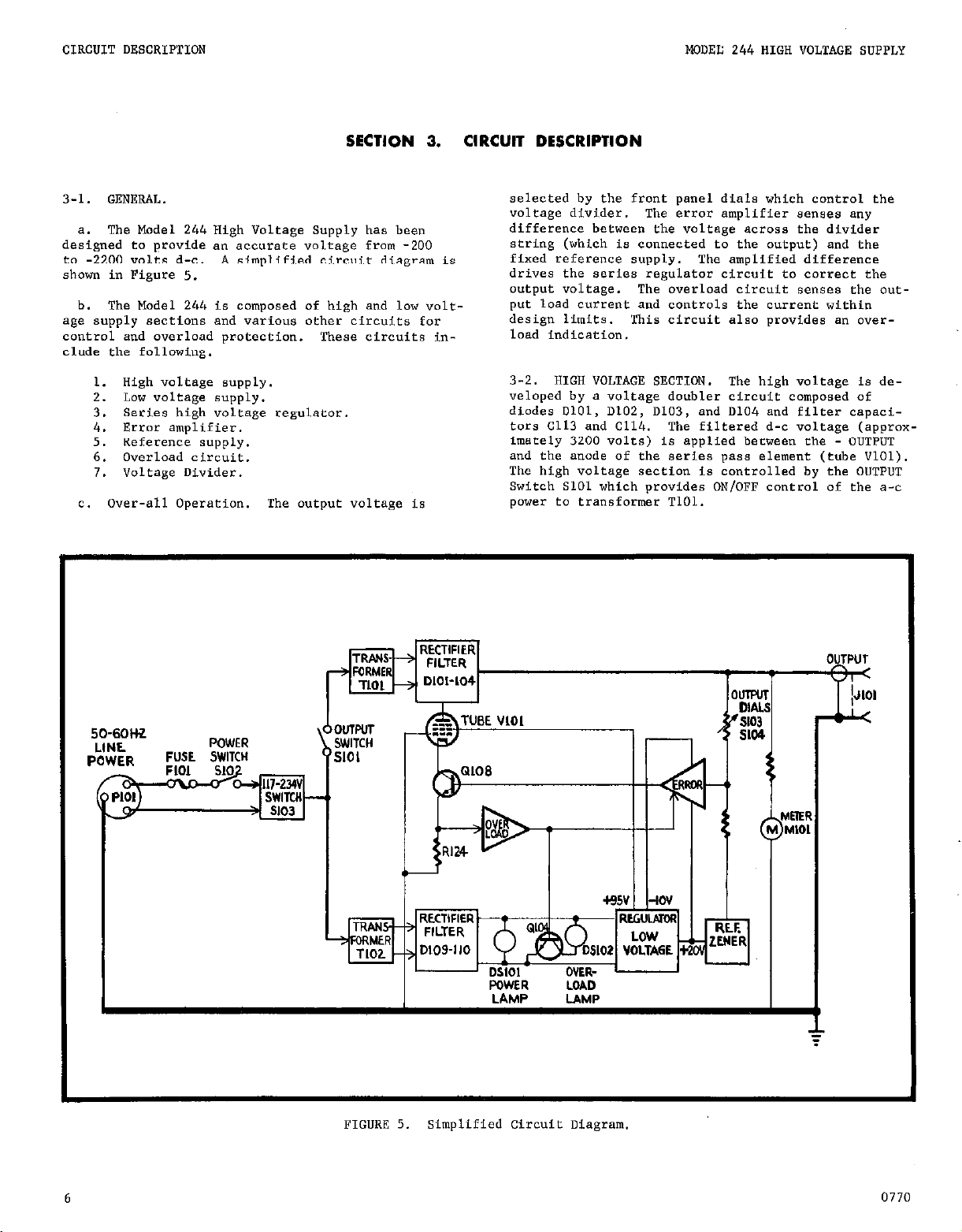
3-1. GENERAL.
a. The Model 244 High Voltage Supply haa been
designed to provide a,, accurate voltage from -200
to -2200 volts d-c.
A
simplified circuit diagram is
shown in Figure 5.
b. The Model 244 is composed of high and low voltage supply sections and various other circuits for
control and overload protection. These circuits include the following.
1. High voltage supply.
2. LOW voltage supply.
3. Series high voltage regulator.
4.
Error amplifier.
5. Reference supply.
6. Overload circuit.
7. Voltage Divider.
C. Over-all Operation.
The output voltage is
selected by the front panel dials which control the
voltage divider. The error amplifier senses any
difference between the voltage across the divider
string (which is connected to the output) and the
fixed reference supply.
The amplified difference
drives the series regulator circuit to correct the
output voltage.
The overload circuit senses the output load current and controls the current within
design limits.
This circuit also provides an over-
load indication.
3-2. HIGH VOLTAGE SECTION.
The high voltage is developed by a voltage doubler circuit composed of
diodes 0101, DlC2, DlC3, and 0104 and fileer capacitars Cl13 and C114.
The filtered d-c voltage (approxFmaeely 3200 volts) is applied between the - OUTPUT
and the anode of the series pass element (tube VlOl).
The high voltage section is controlled by the OUTPUT
Switch SlOl which provides
ON/OFF
control of the a-c
power to transformer TlOl.
R
H
WWER LDAD
LAMP UMP
I
FIGURE 5. Simplified Circuit Diagram.
6
0770
Page 11
MODEL 244 HIGH VOLTAGE SUPPLY
CIRCUIT DESCRIPTION
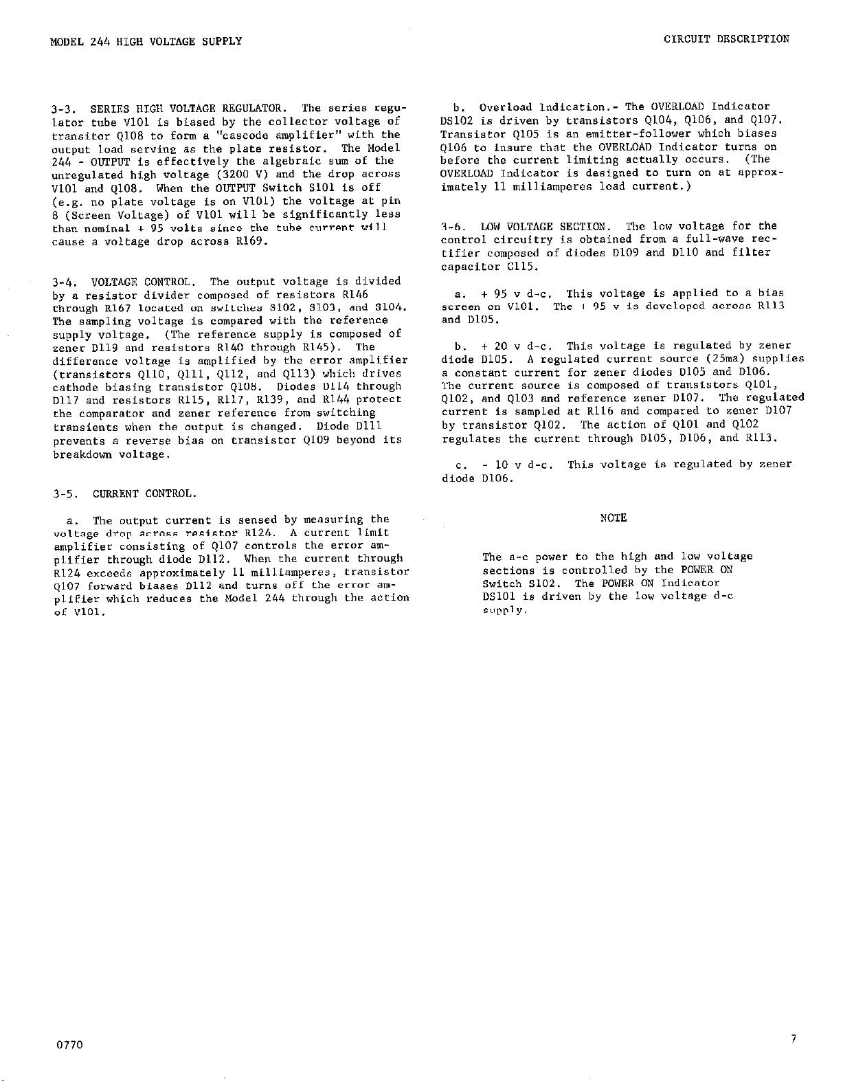
SERIES HIGH VOLTAGE REGULATOR. The series regu-
3-3.
lator tube VlOl is biased by the collector voltage of
transitor QlOE to form a “cascade amplifier” with the
output load serving as the plate resistor. The Model
244 - OUTPUT is effectively the algebraic sum of the
unregulated high voltage (3200 V) and the drop across
“101 and QlOE. When the OUTPUT Switch SlOl is off
(e.g. no plate voltage is on “101) the voltage at pin
8 (Screen Voltage) of VlOl will be significantly less
than nominal + 95 volts since the tube current will
cause a voltage drop across R169.
VOLTAGE CONTROL. The output voltage is divided
3-4.
by a resistor divider composed of resistors R146
through R167 located an switches S102, 5103, and S104.
The sampling voltage is compared with the reference
supply voltage. (The reference supply is composed of
zener D119 and resistors Rl40 through R145). The
difference voltage is amplified by the error amplifier
(transistors QllO, Qlll, Q112, and Q113) which drives
cathode biasing transistor ~108. Diodes 0114 through
Dl17 and resistors R115, R117, R139, and R144 protec?
the comparator and zener reference from switching
transients when the output is changed.
Diode Dill
prevents a reverse bias on transistor QlOV beyond its
breakdown voltage.
3-5. CURRENT CONTROL,
b. Overload Indication.- The OVERLOAD Indicator
05102 is driven by transistors 4104, Q106, and Q107.
Transistor QlO5 is an emitter-follower which biases
9106 to insure that the OVERLOAD Indicator turns on
before the current limiting actually occurs.
(The
OVERLOAD Indicator is designed to turn on at approx-
imately 11 milliamperes load current.)
LOW VOLTAGE SECTION. The low voltage for the
3-6.
control circuitry is obtained from a full-wave rec-
tifier composed of diodes D109 and I1110 and filter
capacitor c115.
+ 95 v d-c. This voltage is applied to a bias
a.
screen on “101. The + 95 v is developed across R113
and D105.
+ 20 v d-c. This voleage is regulaeed by zener
b.
diode D105. A regulated current sowce (25~) supplies
a constant current far zener diodes D105 and D106.
The current source is composed of transistors QlOl,
9102, and Q103 and reference zener D107. The regulated
current is sampled at R116 and compared to zener 0107
by transistor Q102. The action of QlOl and Q102
regulates the currene through 0105, D106, and R113.
- 10 v d-c. This voltage is regulated by zener
c.
diode 0106.
a. The output current is sensed by measuring the
voleage drop across resistor R124. A current limit
amplifier consisting of Q107 controls the error amplifier through diode D112. When the current through
R124 exceeds approximately 11 milliamperes, transistor
Q107 forward biases D112 and turns off the error amplifier which reduces the Model 244 through the action
of VlOl.
NOTE
The a-c power to the high and low voltage
sections is controlled by the POWER ON
Switch ~102. The POWER ON Indicator
ix101 is driven by the low voltage d-c
SUPPlY.
0770
7
Page 12

ACCESSORIES
SECTION 4. ACCESSORIES
4-l.
GENERAL.
be used with the Model 244 to provide additional co"venience and versatility.
The following Keithley accessories can 4-2.
Model 4003A Rack Mounting Kit
MODEL 244 HIGH VOLTAGE SUPPLY
OPERATING
INSTRUCTIONS. A separate Instruction
Manual is supplied with each accessory giving complete
operating information.
Description:
The Model 4003A is a rack mounting kit with overall
dimensions, 5-l/4 inches hFgh x 19 inches wide. Two
cop covers are provided for use with either 10 inch or
13 inch deep instruments.
Application:
The Model 4003A converts the instrument from bench
mounting to rack mounting. It is suitable for mount-
ing one instrument Fn one-half of a standard lY-inch
rack.
Parts Liar:
Item
NO.
1 Top cover, 10" 1 18554B
2
Panel
3 Angle Support 1 17476A
4 Screw, ii10 x 318" 4 ---
5 Connecting Place 1
6 Screw, #lo x 112" 4 -_-
Adapter Plate 1 17452B
Qty. ,Per
Assemblv Part No.
Keithley
7 Angle 1 14624B
8 Top Cover, 13" 1 20015B
191268
Page 13

MODEL 244 HIGH VOLTAGE SUPPLY
ACCESSORIES
Model 4004A Dual Rack Mounting Kit
Description:
The Model 4004A is a rack mounting kit with overall
dimensions, 5-l/4 inches high x 19 inches wide. Two
top covet-~ are provided for use with either 10 inch
or 13 inch deep instruments.
Application:
The Model 4004A converts the instrument from bench
mounting to rack mounting.
ing two inseruments in a standard 19-inch rack.
It is suitable for mount-
parts List:
Item
NO.
1
4 screw, #lO x l/2
5
6
7
8
9
10
Description
Top cover, 10"
Connecting Plate
screw, (110 x l/2
Angle
Top Cover, 13"
Zee Bracket
Plate (not shown)
Qty. Per
Assembly
Keithley
Part No.
185540
19126A
___
14624B
20015B
1914411
174548
Page 14

ACCESSORIES
MODEL 244 HIGH VOLTAGE SUPPLY
Model 2441 Overload Protection Option
Description:
The Model 2441 when factory installed on the Model
244 provides automatic current limiting of the Model
244 output.
Specifications:
OVERLOAD:
current limiting of the Model 244 when the overload input voltage to the Model 2441 exceeds
approximately +1.4 volts.
SENSITI"IT:T:
to +2.OV (+1.7 volts typically) will cause current limiting of the Model 244 output.
OVERLOAD INDICATIONS:
cate whenever rhe Model 244 is in a current
limiting mode.
NOISE IMMUNITY:
signal will not operate overload.
RESPONSE TIME:
"ate 2441 is typically 0.25 seconds (lo-go%).
Model 2441 circuitry provides automatic
An overload input voltage from +1.4V
The overload lamn will indi-
NOTE
The Model 244 will deliver a calibrated
voltage as long as the overload lamp is off
(or the overload input voltage does not
exceed +1.2 volts).
An 8V p-p at 60 Hz overload input
Time for a 2.5" Peak pulse to acti-
Typical Operation:
NOTE
The picaammeter (such as Model 414A) has a 1
volt output for full scale input on the range
selected.
Model 414A increases to approximately 170% of
full scale the Model 414A output,of the 1.7
volts will activate the Model 2441 circuit.
Any
further increase in the current monitored
by the picoammeter will ultimately be limited
to no more than 200% of the full scale range
of the picoammeter. However current limiting
of the Model 244 will occur whenever the Model
244 output exceeds 11 milliamperes s the Model
2441 is activated.
a. Connect the recorder output of a Keithley
picoammeter such as the Model 414A or equivalent to
the Overload Protection Input receptacle 5201.
Figure 1.
b. Select the full scale current range an the
picoammeter for desired operating range.
c. Recorder output of 414A should be in 1 volt
mode.
d. Operate the Model 244 as described in gecrion
2.
If the current monitored by the
see
10
MODEL 244-2441
MODEL 244-2441
I
I
T Ground
FIGURE 6.
System
PICOAMMETER
PICOAMMETER
r-l
Overload Protection Connection Diagram.
0976
Page 15

MODEL 244 HIGH VOLTAGE SUPPLY
ACCESSORIES
Theory of operation far Model
24640A.)
a. The Model
2441
Option provides current limiting
2441:
(See Schematic
control when used with a ,,icoammeter with a 1 volt
output. The Overload Protection Input 5201 requires
an input signal between 1.4 to 2.0 volts d-c.
Model
2441
circuit activates the Model 244 control
The
circuit by meant of transistor switch Q202. The
Model
2441
filter circuit prevents false overloads
due to 60 Hz noise while not affecting the response
which is approximately
0.25
seconds (10-W% rise
the).
b. 'rhe
fallower transistor
switch
2441
Circuit is composed of an emitter
Q201
Q202
which is paralleled wieh the Model 244
which drives a transistor
overload transistor switch 4107. A filter circuit
is composed of R203 and C2Ol.
Replaceable Parts for Model 2441:
C*l-C"it
Mfr. Mfr. Keithley
oesig. oescription Code oesig. Part NO.
5201 COll"eCtOr
--
Cable, 3 ft., k&es
APH so-PC2M
a-233
with 5201) K-I -- 3991
Q201
Q202
Transistor F-I
Transistor
F-l
2N3565
2N3565
'i-G-39
'K-39
R201 Resistor,lMn,l0%,1/2W A-B EB Rl-1M
R202 Resistar.3.9Kn.l0%.1/2W A-B EB Rl-3.9K
R203 ~~~~~~~~~ m,io%,i/2w ~-8 EB n-x
R204
R205
c201
-_
5107
Resistor,
10Kn,10%,1/2W
n-B EB
Resistor,100K~,10%,1/2W h-B EB
u-c
Capacitor, 22ufd,20"
K22JZOK
Stand off K-I -COll”eCt’X
K-I -- SpCXid
Rl-1OK
Rl-100K
CSO-2x4
ST-25
0976
FlClmE 7.
Overload Protection circuit Diagram.
Page 16

ACCESSORIES
MODEL 244 HXH VOLTAGE SUPPLY
MH” connector, cs-191
D~SCt-ipfiOll:
TL- mv ~..-..~~~nr o..nnli~A . ..lrh the instrument is a
------TOT. This part
Il.
Assembly Instructions:
Application:
The connector should be used with low noise coaxial
cables such as RG58A/U or RG59/U.
The cable size
used with this connector should not exceed .257in. 0.1)
12
Fold brald back over brald clnp and
3.
trim .I ,kwn. Cut dlelectrlc and center
conductor to 7/W’ dimension then
strip dlelsctrlc to .470 dimension.
4. Solder contact to center conductor.
Slide back end p.rts forward then
5.
thread assembly into connector and
lock securely.
split by brald clamp.
“ee qmket must be
0870
Page 17

MODEL 244 HIGH VOLTAGE SUPPLY
REPLACEABLE PARTS
SECTION 5.
REPLACEABLE PARTS LIST: This section contains t”rer’s Part Number, and ehe Keithley Part Number.
5-l.
REPLACEABLE PARTS
a list of camponen~s used in this instrument for user Also included is a Figure Reference Number where
reference. The Replaceable Parts List describes the applicable. The complete name and address af each
individual parts giving Circuit Designation, Descrip- Manufacturer is listed in the CODE-TO-NAME Listing
tion, Suggested Manufacturer (Code Number), Manufac- following the parts list.
TABLE 5-l.
Abbreviations and Symbols
A
i ampere
Cb”ar : Carbon Variable
cem : ceramic oisc
Cer Trimmer ; Ceramic
Chip
: composition
Trimmer
: Deposit
DCb : Deposited Carbon
Desig. : Designation
EAL i Electrolytic, Aluminum
ETB : Electrolytic, tubular
ETT
i Electrolytic, tantalum
F i farad
Fig :
GCb i
Fig”?-+
Glass enclosed Carbon
k kilo (10-3)
P
M
micro (10.6)
~~~ (106)
Manufacturer ” : valt Mfr. i
MtF : Metal Film
MY
NO.
Mylar W : watt
Number
; ohm
n
pica (10-'2)
i
P
PC
: Printed Circuit
POly
; Polystyrene
Ref.
: Reference
TC”
i Tinner Copperweld
ww
i Wirewound
ww”ar :
Wirewound Variable
5-2. ELECTRICAL SCHEMATICS AND DlAGRANS. Schemaeics
and diagrams are included to describe the electrical
Sales Service Department, Keithley lii~truments, Inc.
or your nearest Keirhley representative.
circuits as discussed in Section 3. Refer to Table
5-2 which identifies all schematic part numbers
b. When ordering parts, include the following in-
included. formation.
1. Instrument Model Number.
HOW TO “SE THE REPLACEABLE PARTS LIST. This
5-3.
Parts Lise is arranged such that the individual types
Of components are listed in alphabetical order. The
parts for the instrument’s Main Chassis are listed
2. Inserument Serial Number.
3. Pare Description.
4.. Schematic Circuit Designation
5. Keithley Part Number.
followed by printed circuit boards and other subassemblies.
c. All pares listed are maintained in Keithley
spare Parts Stock.
available upan request. Parts identified by the
HOW TO ORDER PARTS,
5-4.
Keithley Manufacturing Cade Number 80164 should be
ordered directly fram Keithley Instruments, Inc.
a.
Replaceable parts may be ordered through the
TABLE 5-2.
Circuit Designaeion
Power supply
PC-270
Any part not listed can be made
Schematic Part Number
243173
0870
13
Page 18

REPLACEABLE PARTS
TABLE 5-3.
Mechanical Parts List
MODEL 244 HIGH
VOLTAGE SUPPLY
Description
1) Chassis
11) Fro,e Panel
Top Cover Assembly
12) Cover, Sheet Metal
13) screws
Handle Assembly
14) Handle
15) Screws #6-32x3/8" R. H. Slotted
Bottom Cover Assembly
2) cover
3) Fastener
Feet Assembly
4) Feet
5) Ball
6) screws #8-32x3/8” Phillips, Pan Head
Tile Bail Assembly
Qll.%ltity
Per Assembly
1
1
___
1
4
___
1
2
__1
2
-_-
4
4
4
___
Keithley
Part NO.
24304C
24306C
19057
19055c
W-18
___
190628
FA-54
___
FE-5
FE-6
___
Fig.
7
637
6
6
7
7,
7
7)
Bail
8) Right Assembly
9) Left Assembly
10) Screws 1/6-32x1/4” Phillips, Pan Head
1
1
1
2
171470
19206B
192058
-__
14
1176
Page 19

MODEL 244 HIGH VOLTAGE SUPPLY
REPLACEABLE PARTS
I
FIGURE 8. To,, Cover Assembly.
-
1176
15
Page 20

REPLACEABLE PARTS
MODEL 244 HIGH VOLTAGE SUPPLY
Cl16
Cl17
5104
5105
5106
5107
5108
___
0.1 IIF
0.1 !JF
0.1 VF
0.1 !lF
.02 UP
0.1 UP
0.1 UF
22 PP
33 PF
.02 PF
100 PP
0.1 !lF
1.0 UP
1.0 UP
40 !lF
0.1 PP
0.1 "F
15”
15"
15"
15"
600"
250"
250"
600"
600"
600"
600"
4OOOV
2000"
2000"
350"
4ooov
250"
connector, ~lnl-P" (Solde
connector, Mini-P" (Solde
connector, mini-P" (S&de
Receptacle, female
Connecfor, male (mate far J108)
890159
890159 c93-.lM
c93-.lM
890159 c93-.l.M
890159
C93-.lM
SW.02 C22-.02M
CZJOAE Cl,&.lM
C28OAE C17G.l"
ED-47
c22-22P
ED-33 cx-3%
ED-.02
ED-100
C22-.02M
CL*-1OOP
LQ40104X c192-.lM
LQ20105X c191-lM
LQ20105X
TVA1611 C23-40M
C191-lM
LQ40104X c192-.lM
C178-.1M
CS-236 10
246588
10
BRG
Bps.
BRG
BRG
BRG
BRG
K-I
CiSOAE
20052 lx-237 3
47439 E-236 10
47439
47439 CS-236 10
47439 cs-236 10
47439 cs-236 10
APH UG93l/V cs-190 io
Am
"G-932AIU
cs-191 10
Mfr.
Code
S-T
S-T
S-T
S-T
Mfr.
Part NO.
3CFS25
3CFS25 RF-49 10
3CFS25
3CFS25
Keichley Fi.g .
Pare NO. Ref.
RF-49
RF-49 IO
RF-49
ITT Z"20 m-25
DIG 1N302OA m-39
DIG
T-I
MOT
MOT
T-I
lN713
18645
lN4006 RF-38
IN4006 RF-38
lA645 RF-14
T-I IN645
T-I
T-I
T-1
T-I
MOT
MOT
lN914
lN645
lN645
IN645 RF-14
IN4006
UT4006
MOT IN938
S-T
vR47
m-14
w-14
RF-14
RF-28 >
RF-14
w-14
RF-38
RF-38
Z-6
25725A
10
10
10
10
10
10
10
Page 21

MODEL 244 HIGH VOLTAGE SUPPLY
REPLACEABLE PARTS
MISCELLANEOUS
circuit
rlesig. Type Code
"SlOl
Pilot Lamp, Neon, White Lens
05102 Pilot Lamp, Neon, Red Lens
DS1,03 Pilot Lamp, Neon
PlOl Fuse, Slow-Blow, 0.75 A, 250V
Ml01 Meter
TlOl
Transformer
T102 Transformer
"101 Vacuum Tube
Mfr. Mfr. Keithley Fig!.
1-D
1-D
G-E
BUS
K-I
K-I
K-I
K-I
RESISTORS
circuit
rasig. Value Rating
RlOl
R102
RI03
R104
RI05
R106
R107
R108
R109
RllO
Rlll
R112
8113
R114
R115
100 n
IK 0
4.7M n
4.7M n
4.7M n
4.7M n
4.7M n
4.m 0
600K n
600K n
600K R
600K 0
2.5K 0
2K n
1K n
lO%, l/4 w
IO%, l/4 w
lO%, 1/2 w
lo%, l/2 w
lO%, l/2 w
lO%, l/2 w
lo%, l/2 w
lO%, l/2 w
l%, l/2 w
l%, l/2 w
1%. l/2 w
l%, l/2 w
5%, 10 w
1%, l/2 w
l%, l/8 W
TYPe
Mfr.
Code
OHM
OHM
A-B
A-B
A-B
A-B
A-B
A-B
DLE
DLE
DLE
DLE
OHM
IRC
IRC
Part No.
Pare NO. Ref.
2100 PL-49
2100
PL-50
NE-83 PL-41
MDL F"-19
___
__.
___
Mfr.
Part NO.
RC07
RC07
EB
B8
EB
EB
EB
ED
DCF-l/2
DCF-l/2
DCF-l/2
cm-l/2
D57F
CEC
CEA
m-87
TR-134
TR-131
W-8068
Keithley
Part No.
K76-100
R76-1K
RI-4.7M
Rl-4.7M
Rl-4.7M
RI-4.7M
Rl-4.7M
RI-4.7M
R12-600K
RlZ-600K
K12-600K
RlZ-600K
R5-2.5K
R94-2K
R88-1K
2
2
10
3
2
10
10
10
Fig.
Ref.
10
10
10
10
10
10
10
10
LO
10
10
10
10
1.0
10
R116
R117
RI18
RI19
RI20
RI21
R122
R123
R124
R125
R126
F.127
R128
R129
it130
RI31
R132
R133
RI34
R135
RI36
R137
R138
R139
R140
402 5,
1K n
33K n
220K n
4.02KR
47K n
4x n
47K n
*Selected R
4.7K n
4.7K n
14 R
15K n
30.lKn
45.3Kcl
47K n
33K n
18K n
120K n
1.5M n
475K R
1K R
1K R
1K R
604 n
1%. l/2 w
l%, l/8 w
lO%, l/2 w
lo%, l/2 w
l%, l/2 w
lO%, l/2 w
10%. 112 w
lO%, l/2 w
l%, l/2 w
IO%, l/2 w
lO%, l/2 w
l%, l/2 w
lO%, l/2 w
I%, l/2 w
l%, l/2 w
lo%, l/2 w
lO%, l/2 w
lO%, l/2 w
10%, l/2 w
l%, l/2 w
I%, l/2 w
l%, l/2 w
20%, 2w
lO%, l/2 w
I%, l/8 w
IRC
IRC
A-B
A-B
IRC
A-B
CEC
CEA
ES
ED
CEC
EB
A-B EB
A-B
IRC
A-P,
A-B
IRC
A-B
IRC
IRC
A-B
A-B
A-B
A-B
IRC
IRC
IRC
CTS
A-B
IRC
EB
CEC
EB
E"
CRC
EB
CEC
CEC
EB
EB
EB
EB
CEC
CEC
CRC
INS-115
EB
CBA
R94-402
R88-1K
Rl-33K
RI-220K
R94-4.02K
Rl-47K
RI-47K
Rl-47K
R94"
Rl-4.7K
Rl-4.7K
R94-14K
Rl-15K
K94-30.x
R94-45.3K
Rl-47K
Rl-33K
RI-18K
Rl-120K
R94-1.5M
R94-475K
R94-1K
RP50-1K
Rl-1K
R88-604
10
10
10
10
10
10
10
10
10
10
10
10
10
10
10
10
10
10
10
10
10
10
10
10
LO
1176
17
Page 22

CitX”it
twig.
Value
RESwrORS (Cont’d)
Mfr.
Raring Type Code
Mfr.
Keithley
Fig.
Pare NO. Pare NO. Ref.
MODEL 244
R141
R142
RI43
RI44
R145
RI46
RI47
RI48
R149
R150
R151
R152
R153
RI54
R155
RI56
R157
R158
R159
R160
F.161
R162
R163
R164
RI65
R166
R167
8.168
R169
R170
R171
R172
R173
RI74
604 n
604 0
16.W 0
100 n
1K fi
5OK 0
402K il
402K a
402K cl
4OZK n
402K n
402K n
402K n
402K 0
402K n
402K n
Not Used
40.2K n
40.2K n
40.2K n
40.x 0
40.2K n
40.2K 0
40.2K 0
40.z n
40.2K n
40.2K 0
Not USed
33K n
60OK Cl
47K n
100 n
100 R
10 Ml?
I%, l/8 w
l%, 1/g w
0.5%, l/2 w
lo%, 1 w
*o%, 2 w
E%, l/2 w
0.5%, l/2 w
0.5%, l/2 w
0.5%, l/2 w
0.5%, l/2 w
0.5%, l/2 w
0.5%, l/2 w
0.5%, l/2 w
0.5%, l/2 w
0.5%, l/2 w
0.5%, l/2 w
0.5%, l/2 w
0.5%, l/2 w
0.5%, l/2 w
0.5%, l/2 w
0.5%, l/2 w
0.5%, l/2 w
0.5%, l/2 w
0.5%, l/2 w
0.5%, l/2 w
lo%, l/2 w
1%, l/2 w
I%, l/2 w
10%. l/4 w
lo%, l/4 w
IO%, l/4 w
MW
MtF
MeF
camp
ww var
cermet var
Mt”
bit”
Me”
Mt”
MtP
MU
Mm
MU
Mm
MCF
MLF
MLF
WCF
Mm
Mm
Mm
MeF
MCF
Mm
MtF
camp
DCb
DCb
00Ulp
camp
camp
IRC
IRC
DLE
A-B
CTS
cm
DLE
DLE
DLE
DLE
DLE
DLE
DLE
DLE
DLE
DLE
DLE
DLE
DLE
DLE
DLE
DLE
DLE
DLE
DLE
DLE
A-B
DLE
DLE
OHM
OHM
CEA
CEA
mm/m9
GB
INS-115
550
MMF1/2T9
mm1,2T9
MMF1/2T9
W1,2T9
blMFll2T9
MMFl/ZW
MMFlf2T9
MMF1/2T9
mm/n9
m!m,2T9
MMFl/ZT2
MMF1/2T2
MMFlf2T2
m1,2T*
MNF1/2T2
mm/2T2
W1/2T2
MMm,2T2
lWF1,2TZ
wm1/2T2
EB
DCF-l/2
OCR-1,2
RCO7
RCO7
RCO7
Rgg-604
Rgg-604
8171-16.Z
RZ-100
RPSO-1K
RP87-50K
8171-402K
R171-402K
R171-402K
R171-4OZK
Rl,l-402K
R171-402K
Rl,l-402K
R171-40x
Rl,l-402K
?.,,I-40ZK
Rl-33K
RlZ-600K
RlZ-600K
R76-100
8.76-100
R76-10~
10
::
10
10
2
10
10
10
10
10
10
10
10
10
10
10
10
10
10
10
10
10
10
10
10
10
10
10
10
10
10
QlOl Silicon NPN, TO-92 case
Q102 Silicon NPN, TO-5 case
Q103
Q104
QlO5
Q106
9107
___
___
Silicon
Silicon - PNP
Silicon
Q108 --Q109
QllO
Qlll
Q112
Q113
Silicon
siticon
Silicon
Silicon
Differential Amp.
*Selected Parr E-44
CirC”it
msig.
SlOl
S102
5103
SlOl
5105
Description
Toggle type, OUTPUT
Toggle type, POWER
Rotary type, 200 " Steps
Rotary type. 20 v steps
Slide type, 117"/234"
18
Mfr.
MOT
P.c*
KCA
RCA
F-I
MOT
F-T
K-I
P-1
F-I
P-I:
F-1
F-I
SWITCHES
Mfr. Mfr. Keirhley Pig.
Code
an904
40346 2167&t* 10
E-47
40317 TG-43 10
40346 TG-44 10
*IT3565
MPSL51
2N3565
m-39
E-72
TG-39
21676A
283565
*Ii5139
2N5139
2N3565
IT122
Part NO. Part NO.
m-39
E-66
TG-66
TG-39
m-73
SW238
Am
20994L" SW4
SW321
K-1
___
SW323 2
24665A
10
10
10
10
10
10
10
10
10
10
Ref.
2
2
2
3
1277
Page 23

MODEL 244
CALIBRATION
SECTION 6.
TEST 6-1.
Test Equipment
Electrometer Keithley
Voltmeter, TRM
Voltmeter, Differential Keithley
O.VCillOSCOp~ Tektronix
Voltmeter DVM Keithley
Micra"oltmeter
Variable Transformer "ari.W
Line Voltage Monitor RCA
Voltage Divider (See Fig. 9) Keithley
Loading Box (See Fig. 8)
Nanovolt source Keithley
6-l. TEST PROCEDORES.
a. General.
1. Maintain caueion and always turn 244 OUTPUT
switch off before working inside chassis and after
each step in this procedure.
Ballafine
Keithley
Keithley
610B
323-01
662
561
160
155
lN-1
LB-l
260
CALIBRATION
2. Amplifier Operation.
a). Output switch on 244 must still be in the
OFF position.
b). Connect 155 Microvoltmeter HI to TP-J and LO
chassis and set range fo 1 volt. Reading On 155
should be .8 volts to 1 volt.
c). Place Nanovolt Source switch in the OFF
position and connect HI of source to TP-E of 244,
LO to chassis.
d). Set dials of Nanovalt Source to 40 mV. See
switch to (-) polarity turn dial up to 60 m".
Reading on 155 should now drop to zero somewhere
between 40 mV and 60 mV indicating amplifier is
operating correctly.
dropping to zero amplifier is not operating prop-
erly.
e). Place Nanovolt Source to the OFF position
and disconnect the Nanovolr Source and fhe 155
from the 244.
3. Zener Current Adjust. Connect DVM HI to TP-F
and LO to TP-G.
to +8.01 "OlfS.
If 1 volt is sluggish when
See Zener Adj. R138 for +7.99 voles
2. The 244 has a unipalar negative output in
which LO and the 244 chassis are the same.
3. Before calibrating the 244 visually inspect it
for incorrect wiring, interchanged parts, diodes in
backwards, bridged or broken tapes. Also mechanical-
ly inspect for smoothly operating controls.
4. Make certain that the 117-234 volt switch is
in Lhe 117 vol? position before calibrating the 244.
b. Preliminary Calibration.
1. Power Supplies.
a). Install one EV-8068 Power Tube (VlOl) and
clamp in place. Make certain tbae all controls
are full CCW and that the Power and output switches
are in the off position.
b). Plug the 244 into a variac and turn power
Connect DVM between TP-H and ground (chassis).
on.
D"M should read -9 volts to -11 volts. Ripple
should be no mare than 5 m" peak-to-peak.
c). Connect DVM beeween W-F and ground (chassis).
DVM should read +18 volts to +22 volts. Ripple
should be no more than 10 m" peak-to-peak.
4. Calibrate Adjust.
a). Place cap on plate of "101 power tube.
b). With 244 OUTPUT switch still off connect HI
of DVM to side of R113 power resistor closest to
side panel of 244 and LO to chassis. Reading
should
volts. Reading should not change more than 2OOm".
Return line voltage to 117 V ac.
volt cal control FULL CCW.
otherwise irreparable damage to range resistors
now rise 5 to 10 volts. Ripple should be more
than 50 m" peak-to-peak.
be
+76 volts eo +92 volts.
c). Vary line voltage from 105 "OlCS to 125
d). Set controls a,, 244 for -1000 volts. 25
CAUTION
If 244 meter swings full scale when OUTPUT
switch is turned oil turn switch OFF IMMEDIATELY,
can OCC"r.
e). Turn 244 OUTPUT switch on DVM reading ehould
0771 19
Page 24

CALIBRATION
MODEL 244
f). Turn the 244 OUTPUT switch off. Connect
the W-1 to the 244 output and the dc output on
the W-1 to the 662. See the 662 controls as
follows:
RANGE FULL SCALE
NULL FULL SCALE
-50 volts
-100 In"
DIALS -10.000
POLARITY
(-)
g). Turn the 244 OUTPUT switch on and set Cal.
Pot. R145 for -10 volts +lO m" reading on 662.
Cut jumpers BCP088 R140, R141 and R142 as necessary to set Cal. Pot.
5.
Overload Calibration
Turn 244
OUTPUT switch off.
a). Connect Loading Box LB-1 Fixture to output
of 244 and set for - and lk-3kV.
put for -2000 Volts.
Turn 244 OUTPUT
set Voltage Out-
8"ltch on.
b). Adjust load until 244 overload light comes
0". If meter on test fixture now reads 11.0 mA
to 11.9 nA resistor R124 is already optimum value.
If reading is not within this range replace R124
with one selected from table below. Turn OUTPUT
switch m before changing resistors.
current in "IA
10.2 - 11.0
12.9 - 13.9 52.3
13.9 - 15.0
R124 in OHMS
42.2
45.3
already installed
48.7
56.2
c). If overload current is less than 10.2 mA or
greater than 15.0 mA change Q107 as IoL dependent
on ",,,o of Q107. Turn 244 OUTPUT switch OFF.
d). Step
Decade Capacitor Box from zero to 1.0
MF in 0.1 MF steps while observing scope. No
oscillations should occur. Disregard line spikes
which may or may not appear.
e). Turn output switch OFF.
8.
234
Volt Operation.
a). Turn 244
Foyer Off and unplug from variac.
Set 117-234 volt switch on rear of 244 to the 234
volt position.
output.
Plug 244 into 234 volt line and turn
Set
244
controls for -200 volt
Power Switch on.
b). Set,ehe 661 controls as follows:
RANGE FULL SCALE
NULL FULL SCALE
DIALS
POLARITY
c). Connect the 662 and
Fixture
Co""ectar.
W-1 to Output of
Connect Scope
High Voltage Divider
244 thrbugh MH" TEE
to ac out conneCtor on
500
volts
10 volts
200.00
(-)
w-1.
d). Set scope controls as follows:
TIME BASE 1 MS/DIV
TRIGGER
VERTICAL
e).
Turn 244 output on.
il volt.
Set Short-Open Switch on W-1 to open.
SENSITIVITY
662
INTERNAL
1 Mv/DIV
should read -200
Noise observed on scope should be less than 200
microvolts.
Set Short-Open Switch on w-1 to
Short.
Short Circuit Output Current.
6.
a). Set 610B on 30 mA range (Multiplier -30
Range 10d3 Amperes Meter -) connect to output jack
on 244.
b). Set all controls on 244 fully CCW and turn
244 OOTPO'I
switch on.
610B should read 12.0 ,,,A
to 14.0 nA and over load light should come on. If
reading is higher change Q107. Turn 244 OUTPUT
switch OFF.
7.
Load Dependent Oscillations.
a). Connect Decade Capacitor Box to 244 output
through MH" TEE Connector.
b). Set oscilloscope as follows:
TIME BASE 1
MSIDIV
TRIGGER INTERNAL
VERTICAL SENSITIVITY 1 WIDIV
c). Connect oscilloscope to 244 output through
NH" TEE connector. Set
244
for -200 volts and
t"rn OUTPUT switch on.
f). Turn 244 output and power switches off.
Unplug 244 from 234 volt line. Set 117-234 volt
switch back to 117 position.
C. Final Calibration.
1. Re-check Zener Adjust and Calibrate.
2.
Load @gulstion.
a). Connect Loading Box LB-l Fixture to 244
output through MHV TEE Connector and set for and lk-3kV.
b). Connect
MVH TEE Connector and connect
662.
Set 244
W-1
controls for -2000,volts.
Divider to 244 output through
W-1 DC output to
20
0771
Page 25

MODEL 244
CALIBRATION
c). Set controls on 662 as follows:
RANGE FULL SCALE 50 volts
NULL FULL SCALE
DIALS
POLARITY
1 In"
20.000
(-)
d). Turn 244 OUTPUT on. 662 should now read
zero center scsle, if not set dials on 662 until
zero reading is obtained.
e). Adjust Load Box between 0 mA and 10 n-4.
Reading an 662 shall not change more than 14
major divisions.
f). Adjust Load Box for 0 mA. Load and vary
line voltage from 105 VAC to 125 VAC. Reading
on 662 shell not change more than +2 major divisions. Return line voltage to 117 "AC.
g). Turn 244 output off.
3. Accuracy.
a). Connect output of 244 to input of W-1 1OO:l
Divider. Connect output of W-1 to input of 662.
b). Set 244 to -200 volts. Set the 662 controls
as follows:
3.4000
3.6000
3.8000
4.0000
2.0000
4.0000
Change 662 to 50
6.000
8.000
10.000
Change 662 to 1
12.000
14.000
16.000
18.000
20.000
TABLE 6-2.
Accuracy Check.
220
240
260
280
300
320
340
360
380
2.178 - 2.222
2.376 - 2.424
2.574 - 2.626
2.772 - 2.828
2.970 - 3.030
3.168 - 3.232
3.366 - 3.434
3.564 - 3.636
3,762 - 3.838
400 3.960 200 1.980 400
3.960 -
volts Range Full Scale
600
800
1000
5.940
7.920 -
9.900 -
volt Null Full Scale
1200
1400
1600
1800
2000
11.880 -
13.860 -
15.840 -
17.820 -
19.800 -
4.040
2.020
4.040
6.060
8.080
10.100
12.120
14.140
16.160
18.180
20.200
RANGE FULL SCALE 5 Volts
NULL FULL SCALE
1 volt
DIALS 2.0000
POLARITY
C-1
c), Turn 244 oofput switch on. The 662 should
now read -2
volts. Turn 244 CAL-25" pot full CW.
The 662 should now read -2.2000 volts to -2.2500
volts.
Return CAL-25" pot full CCW. Turn 244
output switch off.
d). Set 661 control. as follows:
RANGE FULL SCALE
NULL FLlLL SCALE
5 Volts
100 In"
DIALS 2.2000
POLARITY
C-1
e). see 244 controls for -220 volts and turn
244 output s"itch on.
f). Step 662 and 244 thru settings listed in
Table 6-2 take reading shown. Reading must be
within range given. Turn output off when com-
pleted.
4. Output Noise.
a). Set 244 for -2000 volt output. Connect
244 output to input of W-1 and TRMS voltmeter
to ac out connector. Set TRM.9 voltmeter on 300
volt range.
b). Turn 244 output switch on.
Place short-
open switch on W-1 to open and step TRMS volt-
meter to 1 mV range. Meter should read no higher
than 500 microvolts.
1. Vary line voltage from 105 VAC to 125 VAC.
2. Return line voltage to 117 VAC.
c). Place open-short switch on W-1 to short
and turn 244 output and power switches off. Unplug 244 from "ariac.
0771
21
Page 26

--HV
Kn ADJUST FOR II mA LOAD.
TUBE: EV8068
TFtANSFORMER
INSULATION TO 5kV
‘-ym ‘-c MFR: STANCOR P-8190
TRIAD F-52X
-l-IV >
GND F
KEITHLW MOML 669lA
100: I DIVIDER .Ol%
_---
c51 5ocKw 1
I I I I
L “-.-_I pL-K)
< DC OUT
< GND
<AC OUT
Page 27

MODEL 244
CALIBRATION
TABLE 6-3.
Cross-Reference of Manufacturers
CODE
A-B
*WI
APH
APX ,
BIG
BUS
CTS
DIC
DLE
ERI
F-I
G-E
1-D
IRC
ITT
K-I
MOT
OHM
PC1
RCA
S-T
SPG
T-I
NAME AND ADDRESS
Allen-Bradley Corp.
Milwaukee, WI 53204
Arrowhart, Inc.
Hartford, CT 06106
Amphenol
Broadview, IL 60153
Amperex
Elkgrove Village, I,. 60007
Berg Electronics 1°C.
New Cumberland, PA 17070
B"*Sman Mfg. Di".
St. Louis, MO 63017
CTS corporation
Elkhart, IN 46514
Dickson Electronics Corp.
Scottsdale, AZ 85252
Dale Electronics Inc.
Columbus, NE 68601
Erie Technological Products, Inc.
Brie, PA 16512
Fairchild Instruments Corp.
Mountain Vie", CA 94043
General Electric Company
Syracuse, NY 13201
Industrial Devices, Inc.
Edgewater, NJ 07020
IRC Division
BurlinSton, IA 52601
ITT Semiconduceors
Lawrence, MA 01841
Keitbley Instruments, Inc.
Cleveland, OH 44139
Motorola Semiconductor Products, Inc.
Phoenix, AZ 85008
Ohmife Mfg. Co.
Skokie, IL 60076
Plastic Capacitors, Inc.
Chicago, IL 60614
RCA corporation
MOO~~O~, NJ 08050
Sarkes Tarsian, Inc.
Bloamington, IN 47401
Sprague Electric Company
VisaHa, CA 93278
Texas Instruments, Inc.
Dallas. TX 75231
1176
Page 28

Page 29

SWitchcraft, 1°C.
5527 N. Elsfo” he.
Chicago, III. 60630
“670
Page 30

I
I
Page 31

Cl0
RI04
RIO
RIO
Page 32

~RlOl-,
Cl04
r-7
D106.
J102
D105
Cl17 -
D116 ‘- E
D115
.(- ITo
$4
*C/-l
I
. D104
I
$2 g
gE6ge
. D114.-
----- RI03
, RI04
A RI05
/../--- RI06
- RI07
, RI00
u-l
(D
r.
co
a
\Rl69/
f--R113
rDlOh .
LR116J __
Cl07
v
m
N
g
co $
z Fi
JIOI
I
‘cl C&--$
.=
a
i;
W
J104
,-R140j 5 g u ,
mR141 -
‘R142J
s
E LR143JJ,05 -
g cl106
c. yD1081
1
I~,.-
9
yR144\
Cl06
Page 33

Q20 I
3 ro1c
+k
Page 34

I
I
I
4
8
I
I
I
I
; For repair or calibration,
I
I
I
I
I
I
I
I
Sales Service Department
Keithley Instruments, 1~.
28775 Aurora Road Do not write in this space.
Cleveland, Ohio 44139
: User’s Name
; company
REPAIR AND CALIBRATION FORM
please fill out this form and return it with your instrument to:
Telephone
Address
1 Division City
; Date
Model No.
R-
state
Serial No.
Ext.
Zip
j 1.
I
I
I
I
I
I
I
I
I
I
I
I
I
Reason for Return
2. Calibration Report Desired
0 Repair and Recalibration 0 Report of Calibration Certified
0 Recalibration only (No report, except
as specified in item 4 on reverse)*
*If repairs are necessary to meet speci-
fications,
they will be in addition to
Traceable to N.B.S.
0 Calibration Report
~7 Certificate of Compliance
a Norie
the calibration. (for details, see reverse side of this form)
3. To help repair the instrument, briefly describe the problem:
z
JJ ‘L.
I
&
iif
2
a
Is the problem - Constant
Under what conditions does the problem occur:
Control setting e) Line voltage
=)
- Intermittant
f) Other (such as line transients,
b) Approx. Temperature OF
2
u
Approx. Temperature variation * OF
C)
d) Approx. Humidity (high, medium, low)
5. Please draw a block diagram of the system using the Keithley.
nent data which can help in the repair. Include charts or other data if available.
Signal Source
Source Impedance
Readout Device:
~Recorder
m Oscilloscope
-Other
0 None
Lengths & Types of Connecting Cables
line variations, etc.)
List any other perti-
I
; 6. What repairs or modifications have been made on this instrument which are not on file
I
I
I
[ 7. Please
I
I
I
I
I
,
t
I
I
with the Keithley Repair Department?
enclose
any other pertinent data and charl;c jvhich you feel might help the
Repair and Calibration Department
Signature
Title
Page 35

CALIBRATIONS AVAILABLE AT KBITHLEY INSTRUMENTS.
Listed and defined below are the four types of calibrations and their associated report
formats which are presently available at Keithley Instruments. They fall into the following categories:
Report of Calibration Certified Traceable to the National Bureau of
1.
standards
Calibration Report
2.
Certificate of Compliance
3.
4. Recalibration
All calibration and certification performed by Keithley Instruments is in accord with
MIL-C-45662A.
Prices shown below are in addition to repair charges for any work necessary to place a
customer’s unit into first class condition prior to the calibration.
Page 36

KEITHLEY INSTRUMENTS, INC.
28775 AURORA ROAD
CLEVELAND, OHIO 44139
SERVICE FORM
MODEL NO. SERIAL NO. P.O. NO. DATE
NAME PHONE
COMPANY
ADDRESS
Describe problem and symptoms using quantitative data whenever possible (enclose
El
readings, chart recordings, e c
Show a block diagram of your measurement system including all instruments connected
El
El
El
(whether power is turned on or not). Also describe signal source.
List the positions of fl controls and switches on both front and rear panels of
the instrument.
4. Describe input signal source levels, frequencies, etc.
t .I
CITY
(Attach additional sheets as necessary).
STATE -
ZIP
List and describe all cables used in the experiment (length, shielding, etc.).
a
List and describe all other equipment used in the experiment. Give control settings
El
for each.
Environment:
El
q
Where is the measurement being performed?
out-of-doors, etc.)
What power line voltage is used?
Ambient temperature? "F. Variation? "F. Rel. Humidity?
Other
Additional Information.
please describe below.)
(If special modifications have been made by the user,
(Factory, controlled laboratory,
Variation? Frequency?
REV 0774
 Loading...