

Page 1

moc.yelhtiek.www
Series 2400 SourceMeter
User’s Manual
2400S-900-01 Rev. K / September 2011
®
ECNEDIFNOC FO ERUSAEM RETAERG A
Page 2

2400 Series SourceMeter
User’s Manual
®
©2011, Keithley Instruments, Inc.
All rights reserved.
Cleveland, Ohio, U.S.A.
Document Number: 2400S-900-01 Rev. K / September 2011
Page 3

The following safety precautions should be observed before using this product and any associated instrumentation.
Although some instruments and accessories would normally be used with non-hazardous voltages, there are
situations where hazardous conditions may be present.
This product is intended for use by qualified personnel who recognize shock hazards and are familiar with the safety
precautions required to avoid possible injury. Read and follow all installation, operation, and maintenance
information carefully before using the product. Refer to the user documentation for complete product specifications.
If the product is used in a manner not specified, the protection provided by the product warranty may be impaired.
The types of product users are:
Responsible body is the individual or group responsible for the use and maintenance of equipment, for ensuring
that the equipment is operated within its specifications and operating limits, and for ensuring that operators are
adequately trained.
Operators use the product for its intended function. They must be trained in electrical safety procedures and proper
use of the instrument. They must be protected from electric shock and contact with hazardous live circuits.
Maintenance personnel perform routine procedures on the product to keep it operating properly, for example,
setting the line voltage or replacing consumable materials. Maintenance procedures are described in the user
documentation. The procedures explicitly state if the operator may perform them. Otherwise, they should be
performed only by service personnel.
Safety Precautions
04/09
Service personnel are trained to work on live circuits, perform safe installations, and repair products. Only properly
trained service personnel may perform installation and service procedures.
Keithley Instruments products are designed for use with electrical signals that are rated Measurement Category I
and Measurement Category II, as described in the International Electrotechnical Commission (IEC) Standard IEC
60664. Most measurement, control, and data I/O signals are Measurement Category I and must not be directly
connected to mains voltage or to voltage sources with high transient over-voltages. Measurement Category II
connections require protection for high transient over-voltages often associated with local AC mains connections.
Assume all measurement, control, and data I/O connections are for connection to Category I sources unless
otherwise marked or described in the user documentation.
Exercise extreme caution when a shock hazard is present. Lethal voltage may be present on cable connector jacks
or test fixtures. The American National Standards Institute (ANSI) states that a shock hazard exists when voltage
levels greater than 30V RMS, 42.4V peak, or 60VDC are present. A good safety practice is to expect that hazardous
voltage is present in any unknown circuit before measuring.
Operators of this product must be protected from electric shock at all times. The responsible body must ensure that
operators are prevented access and/or insulated from every connection point. In some cases, connections must be
exposed to potential human contact. Product operators in these circumstances must be trained to protect
Page 4
themselves from the risk of electric shock. If the circuit is capable of operating at or above 1000V, no conductive part
!
of the circuit may be exposed.
Do not connect switching cards directly to unlimited power circuits. They are intended to be used with impedancelimited sources. NEVER connect switching cards directly to AC mains. When connecting sources to switching cards,
install protective devices to limit fault current and voltage to the card.
Before operating an instrument, ensure that the line cord is connected to a properly-grounded power receptacle.
Inspect the connecting cables, test leads, and jumpers for possible wear, cracks, or breaks before each use.
When installing equipment where access to the main power cord is restricted, such as rack mounting, a separate
main input power disconnect device must be provided in close proximity to the equipment and within easy reach of
the operator.
For maximum safety, do not touch the product, test cables, or any other instruments while power is applied to the
circuit under test. ALWAYS remove power from the entire test system and discharge any capacitors before:
connecting or disconnecting cables or jumpers, installing or removing switching cards, or making internal changes,
such as installing or removing jumpers.
Do not touch any object that could provide a current path to the common side of the circuit under test or power line
(earth) ground. Always make measurements with dry hands while standing on a dry, insulated surface capable of
withstanding the voltage being measured.
The instrument and accessories must be used in accordance with its specifications and operating instructions, or
the safety of the equipment may be impaired.
Do not exceed the maximum signal levels of the instruments and accessories, as defined in the specifications and
operating information, and as shown on the instrument or test fixture panels, or switching card.
When fuses are used in a product, replace with the same type and rating for continued protection against fire hazard.
Chassis connections must only be used as shield connections for measuring circuits, NOT as safety earth ground
connections.
If you are using a test fixture, keep the lid closed while power is applied to the device under test. Safe operation
requires the use of a lid interlock.
If a screw is present, connect it to safety earth ground using the wire recommended in the user documentation.
The symbol on an instrument means caution, risk of danger. The user should refer to the operating instructions
located in the user documentation in all cases where the symbol is marked on the instrument.
The symbol on an instrument means caution, risk of danger. Use standard safety precautions to avoid personal
contact with these voltages.
The symbol on an instrument shows that the surface may be hot. Avoid personal contact to prevent burns.
The symbol indicates a connection terminal to the equipment frame.
If this symbol is on a product, it indicates that mercury is present in the display lamp. Please note that the lamp
must be properly disposed of according to federal, state, and local laws.
Page 5

The WARNING heading in the user documentation explains dangers that might result in personal injury or death.
Always read the associated information very carefully before performing the indicated procedure.
The CAUTION heading in the user documentation explains hazards that could damage the instrument. Such
damage may invalidate the warranty.
Instrumentation and accessories shall not be connected to humans.
Before performing any maintenance, disconnect the line cord and all test cables.
To maintain protection from electric shock and fire, replacement components in mains circuits - including the power
transformer, test leads, and input jacks - must be purchased from Keithley Instruments. Standard fuses with
applicable national safety approvals may be used if the rating and type are the same. Other components that are
not safety-related may be purchased from other suppliers as long as they are equivalent to the original component
(note that selected parts should be purchased only through Keithley Instruments to maintain accuracy and
functionality of the product). If you are unsure about the applicability of a replacement component, call a Keithley
Instruments office for information.
To clean an instrument, use a damp cloth or mild, water-based cleaner. Clean the exterior of the instrument only.
Do not apply cleaner directly to the instrument or allow liquids to enter or spill on the instrument. Products that consist
of a circuit board with no case or chassis (e.g., a data acquisition board for installation into a computer) should never
require cleaning if handled according to instructions. If the board becomes contaminated and operation is affected,
the board should be returned to the factory for proper cleaning/servicing.
Page 6

Table of contents
Section Title Page
1 Getting Started
General information ....................................................................... 1-2
Contact information ................................................................. 1-2
Manual addenda ..................................................................... 1-2
Safety symbols and terms ...................................................... 1-2
Inspection ............................................................................... 1-3
Options and accessories ........................................................ 1-3
Product overview ........................................................................... 1-5
Front and rear panel familiarization ............................................... 1-6
Front panel summary .............................................................. 1-6
Rear panel summary .............................................................. 1-7
Power-up ....................................................................................... 1-9
Line power connection ............................................................ 1-9
Power-up sequence .............................................................. 1-10
Line frequency setting ........................................................... 1-11
Fuse replacement ................................................................. 1-11
Cooling fan .................................................................................. 1-12
Display ........................................................................................ 1-13
Display format ....................................................................... 1-13
EDIT key ............................................................................... 1-13
TOGGLE key ........................................................................ 1-13
Status and error messages ................................................... 1-14
Remote display programming ............................................... 1-14
Front panel tests ................................................................... 1-14
Default settings ........................................................................... 1-15
Saving and restoring user setups ......................................... 1-15
Factory default settings ......................................................... 1-16
Remote setups ...................................................................... 1-18
Menus ......................................................................................... 1-19
Page 7

Table of Contents 2400 Series SourceMeter® User’s Manual
Main menu ............................................................................ 1-19
Rules to navigate menus ...................................................... 1-22
Editing source and compliance values ................................. 1-23
Toggling the source and measure display fields ................... 1-23
Disabling front panel display ................................................. 1-24
Configuration menus ............................................................ 1-24
2 Connections
Connection overview ..................................................................... 2-2
Front/rear terminals selection ................................................. 2-2
Connections to DUT ...................................................................... 2-3
Sensing methods .................................................................... 2-5
Guarding methods .................................................................. 2-8
3 Basic Source-Measure Operation
WARNING - CAUTION .................................................................. 3-2
Operation overview ....................................................................... 3-4
Source-measure capabilities .................................................. 3-4
Compliance limit ..................................................................... 3-6
Setting the compliance limit .................................................... 3-8
Basic circuit configurations ..................................................... 3-9
Operation considerations ............................................................ 3-10
Warm-up ............................................................................... 3-10
Auto zero .............................................................................. 3-10
NPLC caching ....................................................................... 3-11
V-source protection ............................................................... 3-12
Source delay ......................................................................... 3-13
Basic source-measure procedure ............................................... 3-15
Front panel source-measure procedure ............................... 3-15
Remote command source-measure procedure .................... 3-18
Measure only ............................................................................... 3-20
Front panel measure only ..................................................... 3-20
Remote command measure only .......................................... 3-21
Sink operation ............................................................................. 3-22
Battery charging/discharging ................................................ 3-22
Sink programming example .................................................. 3-24
4 Ohms Measurements
Ohms configuration menu ............................................................. 4-2
Ohms measurement methods ....................................................... 4-3
Selecting ohms measurement method ................................... 4-4
Ohms measurement procedure .............................................. 4-4
Ohms sensing ............................................................................... 4-6
Page 8

2400 Series SourceMeter® User’s Manual Table of Contents
Sense selection ...................................................................... 4-7
Offset-compensated ohms ............................................................ 4-8
Enabling/disabling offset-compensated ohms ........................ 4-8
Ohms accuracy calculations ................................................... 4-9
Ohms source readback ............................................................... 4-11
Ohms source readback selection ......................................... 4-11
6-wire ohms measurements ........................................................ 4-12
Remote ohms programming ........................................................ 4-13
Remote ohms commands ..................................................... 4-13
Ohms programming example ............................................... 4-14
5 Pulse Mode Operation (Model 2430 only)
Overview ....................................................................................... 5-2
Pulse characteristics ..................................................................... 5-3
Pulse width ............................................................................. 5-4
Output off-time ........................................................................ 5-6
Pulse duty cycle ...................................................................... 5-6
Fast pulse output .................................................................... 5-7
Pulse jitter ............................................................................... 5-8
Pulse energy limitations (10A range) ............................................ 5-9
Pulse Mode configuration ............................................................ 5-10
Front panel Pulse Mode configuration .................................. 5-10
Remote command Pulse Mode configuration ....................... 5-11
Pulse-measure considerations .................................................... 5-12
Measurement speed ............................................................. 5-12
Filter ...................................................................................... 5-12
Auto range ............................................................................ 5-12
Concurrent measurements ................................................... 5-12
Ohms source readback ......................................................... 5-12
Toggle key ............................................................................. 5-13
Offset-compensated ohms .................................................... 5-13
Source delay ......................................................................... 5-13
Trigger delay ......................................................................... 5-14
Input triggers ......................................................................... 5-14
Output triggers ...................................................................... 5-14
Auto output-off ...................................................................... 5-14
Output-off state ..................................................................... 5-15
Turning source on ................................................................. 5-15
SCPI signal oriented measurement commands ................... 5-15
6 Source-Measure Concepts
Compliance limit ............................................................................ 6-2
Types of compliance ............................................................... 6-2
Maximum compliance values .................................................. 6-3
Page 9

Table of Contents 2400 Series SourceMeter® User’s Manual
Compliance examples ............................................................ 6-4
Determining compliance limit .................................................. 6-4
Overheating protection .................................................................. 6-6
Overheating conditions ........................................................... 6-6
Source-delay-measure cycle ......................................................... 6-7
Sweep waveforms .................................................................. 6-9
Operating boundaries .................................................................. 6-10
Source or sink ....................................................................... 6-10
Duty cycle ............................................................................. 6-10
I-Source operating boundaries ............................................. 6-15
V-Source operating boundaries ............................................ 6-19
Source I measure I and source V measure V ....................... 6-22
Basic circuit configurations .......................................................... 6-23
Source I ................................................................................ 6-23
Source V ............................................................................... 6-24
Measure only (V or I) ............................................................ 6-25
Guard .......................................................................................... 6-27
Cable guard .......................................................................... 6-27
Ohms guard .......................................................................... 6-28
Guard sense ......................................................................... 6-32
Data flow ..................................................................................... 6-34
Buffer considerations ............................................................ 6-36
7 Range, Digits, Speed, and Filters
Range and digits ........................................................................... 7-2
Range ..................................................................................... 7-2
Digits ....................................................................................... 7-5
Remote range and digits programming .................................. 7-5
Speed ............................................................................................ 7-7
Setting speed .......................................................................... 7-7
Remote speed programming .................................................. 7-8
Filters ............................................................................................ 7-9
Front panel filter control ........................................................ 7-10
Remote filter programming ................................................... 7-12
8 Relative and Math
Relative ......................................................................................... 8-2
Front panel rel ......................................................................... 8-2
Remote rel programming ........................................................ 8-3
Math operations ............................................................................ 8-4
Built-in math functions ............................................................ 8-4
Front panel math operations ................................................... 8-6
Remote math operations ........................................................ 8-7
User-defined math functions ................................................... 8-7
Page 10

2400 Series SourceMeter® User’s Manual Table of Contents
9 Data Store
Data store overview ...................................................................... 9-2
Front panel data store ................................................................... 9-2
Storing readings ...................................................................... 9-2
Recalling readings .................................................................. 9-2
Buffer statistics ....................................................................... 9-3
Timestamp format ................................................................... 9-4
Buffer considerations .............................................................. 9-5
Remote command data store ........................................................ 9-5
Data store commands ............................................................. 9-5
Data store programming example .......................................... 9-5
10 Sweep Operation
Sweep types ................................................................................ 10-2
Linear staircase sweep ......................................................... 10-2
Logarithmic staircase sweep ................................................ 10-4
Abort on compliance ............................................................. 10-5
Custom sweep ...................................................................... 10-6
Source memory sweep ......................................................... 10-6
Configuring and running a sweep ............................................. 10-12
Front panel sweep operation .............................................. 10-12
Remote sweep operation .................................................... 10-19
Pulse Mode sweeps (Model 2430 only) .................................... 10-24
Front panel Pulse Mode sweep procedure ......................... 10-25
Remote Pulse Mode sweep operation ................................ 10-26
11 Triggering
Front panel trigger operation ....................................................... 11- 2
Front panel trigger model ...................................................... 11-2
Configuring triggering ........................................................... 11 - 7
Remote trigger operation .......................................................... 11-10
Remote trigger model ......................................................... 11-10
Remote trigger commands ................................................. 11-18
Trigger link ................................................................................. 11-19
Input trigger requirements ................................................... 11- 19
Output trigger specifications ............................................... 11-20
Pulse Mode triggering (Model 2430) ......................................... 11-20
Trigger models .................................................................... 11-20
Invalid trigger settings ......................................................... 11- 2 4
12 Limit Testing
Types of limits ............................................................................. 12-2
Pass/fail information ............................................................. 12-2
Page 11

Table of Contents 2400 Series SourceMeter® User’s Manual
Data flow ............................................................................... 12-3
Limit 1 test (compliance) ....................................................... 12-3
Limit 2, limit 3, and limit 5-12 tests ........................................ 12-3
Limit 4 ................................................................................... 12-3
Limit test modes ................................................................... 12-3
Binning .................................................................................. 12-4
Operation overview ..................................................................... 12-4
Grading mode ....................................................................... 12-4
Sorting mode ........................................................................ 12-7
Binning systems ........................................................................ 12-10
Handler interface ................................................................ 12-10
Handler types ..................................................................... 12-12
Basic binning systems ........................................................ 12-13
Digital output clear pattern .................................................. 12-14
Configuring and performing limit tests ....................................... 12-16
Configuring limit tests ......................................................... 12-16
Performing front panel limit tests ........................................ 12-19
Remote limit testing ................................................................... 12-20
Limit commands ................................................................. 12-20
13 Digital I/O Port, Output Enable, & Output Configuration
Digital I/O port ............................................................................. 13-2
Port configuration ................................................................. 13-2
Digital output configuration ................................................... 13-3
Controlling digital output lines ............................................... 13-4
Output enable line ....................................................................... 13-6
Front panel output configuration ................................................. 13-7
Configure OUTPUT menu .................................................... 13-8
Output-off states ................................................................... 13-9
Output-off states and inductive loads ................................. 13-11
Remote output configuration ..................................................... 13-12
Output configuration commands ......................................... 13-12
14 Remote Operations
Differences: remote vs. local operation ....................................... 14-2
Operation enhancements (remote operation) ....................... 14-2
Local-to-remote transition ..................................................... 14-2
Remote-to-local transition ..................................................... 14-3
Selecting an interface .................................................................. 14-3
GPIB operation ............................................................................ 14-4
GPIB standards .................................................................... 14-4
GPIB connections ................................................................. 14-4
Primary address ................................................................... 14-4
General bus commands .............................................................. 14-5
Page 12

2400 Series SourceMeter® User’s Manual Table of Contents
Front panel GPIB operation ........................................................ 14-5
Error and status messages ................................................... 14-5
GPIB status indicators .......................................................... 14-5
LOCAL key ........................................................................... 14-6
Programming syntax ................................................................... 14-6
Command words ................................................................... 14-6
Query commands ................................................................. 14-9
Case sensitivity ..................................................................... 14-9
Long-form and short-form versions ....................................... 14-9
Short-form rules .................................................................. 14-10
Response messages .......................................................... 14-12
Message exchange protocol ............................................... 14-13
RS-232 interface operation ....................................................... 14-13
Sending and receiving data ................................................ 14-13
Baud rate ............................................................................ 14-14
Data bits and parity ............................................................. 14-14
Terminator ........................................................................... 14-14
Flow control (signal handshaking) ...................................... 14-15
RS-232 connections ........................................................... 14-15
Error messages .................................................................. 14-17
15 Status Structure
Overview ..................................................................................... 15-2
Status byte and SRQ ............................................................ 15-2
Status register sets ............................................................... 15-2
Queues ................................................................................. 15-2
Clearing registers and queues .................................................... 15-4
Programming and reading registers ............................................ 15-5
Programming enable registers .............................................. 15-5
Reading registers .................................................................. 15-6
Status byte and service request (SRQ) ....................................... 15-7
Status byte register ............................................................... 15-8
Service request enable register ............................................ 15-9
Serial polling and SRQ ......................................................... 15-9
Status byte and service request commands ....................... 15-10
Status register sets .................................................................... 15-11
Register bit descriptions ..................................................... 15-11
Condition registers .............................................................. 15-16
Event registers .................................................................... 15-16
Event enable registers ........................................................ 15-17
Queues ...................................................................................... 15-18
Output queue ...................................................................... 15-18
Error queue ......................................................................... 15-19
Page 13

Table of Contents 2400 Series SourceMeter® User’s Manual
16 Common Commands
Command summary .................................................................... 16-2
Command reference ................................................................... 16-3
*IDN? — identification query ................................................ 16-3
*OPC — operation complete ................................................ 16-3
*OPC? — operation complete query .................................... 16-3
*SAV <NRf> — save ............................................................. 16-3
*RCL <NRf> — recall ........................................................... 16-3
**RST — reset ...................................................................... 16-4
*TRG — trigger ..................................................................... 16-4
**TST? — self-test query ...................................................... 16-4
*WAI — wait-to-continue ....................................................... 16-5
17 SCPI Signal Oriented Measurement Commands
Command summary .................................................................... 17-2
Configuring measurement function ............................................. 17-2
:CONFigure:<function> ......................................................... 17-2
Acquiring readings ...................................................................... 17-3
:FETCh? ............................................................................... 17-3
[:SENSe[1]]:DATA[:LATest]? ................................................. 17-4
:READ? ................................................................................. 17-4
:MEASure[:<function>]? ....................................................... 17-5
18 SCPI Command Reference
Reference tables ......................................................................... 18-2
Calculate subsystems ............................................................... 18-26
CALCulate[1] ............................................................................. 18-26
Select (create) math expression name ............................... 18-26
Assign unit suffix ................................................................. 18-28
Define math expression ...................................................... 18-29
Enable and read math expression result ............................ 18-32
CALCulate2 ............................................................................... 18-33
Select input path ................................................................. 18-33
Null feed reading ................................................................ 18-34
Read CALC2 ...................................................................... 18-34
Configure and control limit tests ......................................... 18-35
Composite testing ............................................................... 18-39
Clear test results ................................................................. 18-42
CALCulate3 ............................................................................... 18-43
Select statistic ..................................................................... 18-43
Acquire statistic ................................................................... 18-43
DISPlay subsystem ................................................................... 18-44
Control display .................................................................... 18-44
Page 14

2400 Series SourceMeter® User’s Manual Table of Contents
Read display ....................................................................... 18-46
Define :TEXT messages ..................................................... 18-46
FORMat subsystem .................................................................. 18-47
Data format ......................................................................... 18-47
Data elements ..................................................................... 18-49
CALC data elements ........................................................... 18-53
Byte order ........................................................................... 18-54
Status register format .......................................................... 18-54
OUTPut subsystem ................................................................... 18-55
Turn source on or off ........................................................... 18-55
Output enable line ............................................................... 18-56
Output-off states ................................................................. 18-56
ROUTe subsystem .................................................................... 18-57
Select input jacks ................................................................ 18-57
SENSe1 subsystem .................................................................. 18-58
Select measurement functions ........................................... 18-58
Select measurement range ................................................. 18-62
Select auto range ................................................................ 18-65
Current range holdoff .......................................................... 18-66
Set compliance parameters ................................................ 18-67
Set measurement speed ..................................................... 18-69
Configure and control filter .................................................. 18-70
SOURce subsystem .................................................................. 18-71
SOURce[1] .......................................................................... 18-71
Control source output-off .................................................... 18-71
Select function modes ........................................................ 18-72
Select sourcing mode ......................................................... 18-73
Select range ........................................................................ 18-74
Set amplitude for fixed source ............................................ 18-77
Set voltage limit .................................................................. 18-79
Set delay ............................................................................. 18-82
Configure voltage and current sweeps ............................... 18-83
Abort on compliance ........................................................... 18-90
Configure list ....................................................................... 18-91
Configure memory sweep ................................................... 18-93
Set scaling factor ................................................................ 18-95
Soak time ............................................................................ 18-96
Pulse Mode delays (Model 2430 only) ................................ 18-97
SOURce2 ............................................................................ 18-98
Setting digital output ........................................................... 18-98
Clearing digital output ......................................................... 18-99
STATus subsystem .................................................................. 18-101
Read event registers ......................................................... 18-101
Program event enable registers ........................................ 18-101
Read condition registers ................................................... 18-101
Page 15

Table of Contents 2400 Series SourceMeter® User’s Manual
Select default conditions ................................................... 18-102
Error queue ....................................................................... 18-102
SYSTem subsystem ................................................................ 18-103
Default conditions ............................................................. 18-103
Control remote sensing .................................................... 18-104
Select guard mode ........................................................... 18-105
Initialize memory ............................................................... 18-106
Control beeper .................................................................. 18-106
Control auto zero .............................................................. 18-107
Control NPLC caching ...................................................... 18-107
Select power line frequency setting .................................. 18-108
Error queue ....................................................................... 18-109
Simulate key presses ....................................................... 18-110
Read version of SCPI standard ........................................ 18-112
RS-232 interface ............................................................... 18-112
Query timestamp .............................................................. 18-112
Reset timestamp ............................................................... 18-113
Auto reset timestamp ........................................................ 18-113
Auto range change mode ................................................. 18-113
TRACe subsystem .................................................................. 18-114
Read and clear buffer ....................................................... 18-114
Configure and control buffer ............................................. 18-114
Select timestamp format ................................................... 18-116
TRIGger subsystem ................................................................ 18-116
Clear input triggers ........................................................... 18-116
Initiate source/measure cycle ........................................... 18-117
Abort source/measure cycle ............................................. 18-117
Program trigger model ...................................................... 18-117
Accuracy calculations ................................................................... A-2
Measure accuracy ................................................................. A-2
Source accuracy .................................................................... A-2
Source-Delay-Measure (SDM) cycle timing ................................. A-3
Definitions .............................................................................. A-3
Timing diagrams .................................................................... A-4
Introduction .................................................................................. B-2
Status and error messages .......................................................... B-2
Eliminating common SCPI errors ................................................. B-8
Introduction .................................................................................. C-2
FETCh? ................................................................................. C-3
CALCulate[1]:DATA? ............................................................. C-4
CALCulate2:DATA? ............................................................... C-4
TRACe:DATA? ....................................................................... C-4
CALCulate3:DATA? ............................................................... C-4
Introduction .................................................................................. D-2
Bus description ............................................................................. D-3
Page 16

2400 Series SourceMeter® User’s Manual Table of Contents
Bus lines ....................................................................................... D-5
Data lines ............................................................................... D-5
Bus management lines .......................................................... D-5
Handshake lines .................................................................... D-5
Bus commands ............................................................................ D-6
Addressed multiline commands ............................................. D-8
Address commands ............................................................... D-8
Unaddress commands ........................................................... D-8
Common commands .............................................................. D-8
SCPI commands .................................................................... D-8
Command codes .................................................................... D-9
IEEE command groups ........................................................ D-11
Interface function codes ............................................................. D-12
Introduction .................................................................................. E-2
Introduction ................................................................................... F-2
Overview ....................................................................................... F-2
Description .............................................................................. F-2
Operation ...................................................................................... F-3
DUT connections .................................................................... F-3
Contact check threshold resistances ...................................... F-4
Contact check failure indications ............................................ F-5
Auto and manual ohms ........................................................... F-5
Trigger model operation .......................................................... F-6
Sweep and binning considerations ............................................... F-6
Sweep limitations .................................................................... F-6
Limit test sequence ................................................................. F-7
Binning failure indications (grading mode) ............................ F-10
Front panel contact check operation ........................................... F-11
Menu selections .................................................................... F-11
Using contact check .............................................................. F-12
Remote contact check operation ................................................. F-14
Contact check remote commands ........................................ F-14
Contact check programming example .................................. F-15
Contact check command reference ............................................ F-17
Configure and control contact check .................................... F-17
Configure and control contact check limit test ...................... F-17
Configure and control contact check event detection ........... F-19
Contact check defaults ................................................................ F-20
Introduction .................................................................................. G-2
Selecting the 488.1 protocol ......................................................... G-2
Protocol differences ..................................................................... G-3
Message exchange protocol (MEP) ....................................... G-3
Using SCPI-based programs ................................................. G-4
NRFD hold-off ........................................................................ G-4
NDAC hold-off ........................................................................ G-4
Page 17

Table of Contents 2400 Series SourceMeter® User’s Manual
Trigger-on-talk ....................................................................... G-5
Message available ................................................................. G-5
General operation notes ........................................................ G-5
Page 18

1
Getting Started
• General information — Covers general information that includes contact
information, safety symbols and terms, inspection, and available options
and accessories.
• Product overview — Summarizes the features of the SourceMeter.
• Front and rear panel familiarization — Summarizes the controls and con-
nectors of the instrument.
• Power-up — Covers line power connection, line voltage settings, fuse
replacement, and the power-up sequence.
• Cooling fan — Covers the cooling fan in the Models 2410, 2420, 2425,
2430, and 2440.
• Display — Provides information about the SourceMeter display.
• Default settings — Covers factory default setups and saving and recalling
user setups.
• Menus — Covers the main and configuration menus as well as rules to
navigate menus.
Page 19

1-2 Getting Started 2400 Series SourceMeter® User’s Manual
!
General information
Contact information
Worldwide phone numbers are listed at the front of this manual. If you have any
questions, please contact your local Keithley representative or call one of our
Application Engineers at 1-800-348-3735 (U.S. and Canada only).
Manual addenda
Any improvements or changes concerning the instrument or manual will be
explained in an addendum included with the manual. Be sure to note these
changes and incorporate them into the manual.
Safety symbols and terms
The following symbols and terms may be found on the instrument or used in this
manual.
The symbol on an instrument indicates that the user should refer to the operating instructions located in the manual.
The symbol on the instrument shows that high voltage may be present on
the terminal(s). Use standard safety precautions to avoid personal contact with
these voltages.
The WARNING heading used in this manual explains dangers that might result in
personal injury or death. Always read the associated information very carefully
before performing the indicated procedure.
The CAUTION heading used in this manual explains hazards that could damage
the instrument. Such damage may invalidate the warranty.
Page 20

2400 Series SourceMeter® User’s Manual Getting Started 1-3
Inspection
The SourceMeter was carefully inspected electrically and mechanically before
shipment. After unpacking all items from the shipping carton, check for any obvious signs of physical damage that may have occurred during transit. (There may
be a protective film over the display lens, which can be removed.) Report any
damage to the shipping agent immediately. Save the original packing carton for
possible future shipment. The following items are included with every SourceMeter order:
• SourceMeter with line cord.
• Test leads (Model 8605 for 2400, 2400-C; Model 1754 for all other series
2400 units).
• Accessories as ordered.
• Certificate of calibration.
• User’s Manual.
• Service Manual.
• Support Software Disk including TestPoint instrument library for GPIB and
LabVIEW for Windows driver.
• Manual addenda containing any improvements or changes to the instrument or manual.
If an additional manual is required, order the appropriate manual package (for
example, 2400-901-00). The manual packages include a manual and any pertinent addenda.
Options and accessories
The following options and accessories are available from Keithley for use with the
SourceMeter.
Cables and adapters
Model 2499-DIGIO adapter — Lets you expand the Digital I/O port to 16 bits
instead of 4 bits.
Models 7007-1 and 7007-2 shielded GPIB cables — Connect the SourceMeter to
the GPIB bus using shielded cables and connectors to reduce electromagnetic
interference (EMI). The Model 7007-1 is 1m long; the Model 7007-2 is 2m long.
Models 8501-1 and 8501-2 trigger link cables — Connect the SourceMeter to
other instruments with Trigger Link connectors (e.g., Model 7001 Switch System).
The Model 8501-1 is 1m long; the Model 8501-2 is 2m long.
Model 8502 trigger link adapter — Lets you connect any of the six Trigger Link
lines of the SourceMeter to instruments that use the standard BNC trigger connectors.
Page 21

1-4 Getting Started 2400 Series SourceMeter® User’s Manual
Model 8503 DIN to BNC trigger cable — Lets you connect Trigger Link lines one
(Voltmeter Complete) and two (External Trigger) of the SourceMeter to instruments that use BNC trigger connectors. The Model 8503 is 1m long.
Model 8505 trigger link cable — The Model 8505 is a male to dual-female trigger
link cable.
Rack mount kits
Model 4288-1 single fixed rack mount kit — Mounts a single SourceMeter in a
standard 19-inch rack.
Model 4288-2 side-by-side rack mount kit — Mounts two instruments (Models
182, 428, 486, 487, 2000, 2001, 2002, 2010, 2015, 2400, 2410, 2420, 2425,
2430, 2440, 6430, 6517, 7001) side-by-side in a standard 19-inch rack.
Model 4288-3 side-by-side rack mount kit — Mounts a SourceMeter and a Model
199 side-by-side in a standard 19-inch rack.
Model 4288-4 side-by-side rack mount kit — Mounts a SourceMeter and a 5.25-
inch instrument (Models 195A, 196, 220, 224, 230, 263, 595, 614, 617, 705, 740,
775, etc.) side-by-side in a standard 19-inch rack.
Model 4288-5 dual fixed rack mounting kit — Mounts a SourceMeter and another
3H-inch high instrument (Model 182, 428, 486, 487, 2000, 2010, 2400, 2410,
2420, 2425, 2430, 6430, or 7001), side-by-side in a standard 19-inch rack.
Carrying case
Model 1050 padded carrying case — A carrying case for a SourceMeter. Includes
handles and a shoulder strap.
Page 22

2400 Series SourceMeter® User’s Manual Getting Started 1-5
Product overview
The SourceMeter combines a precise, low-noise, highly stable DC power supply
with a low-noise, highly repeatable, high-impedance multimeter. It has 0.012%
basic accuracy with 5H-digit resolution. At 5H digits, the SourceMeter delivers 520
readings/second over the IEEE-488 bus. At 4H digits, it can read up to 2000 read-
ings/second into its internal buffer. See Appendix A for specifications.
Some additional capabilities of the SourceMeter include:
• Concurrent measurements of all three functions over the remote interface.
• Source-measure sweep capabilities (linear and logarithmic staircase
sweeps, source sweep list of up to 2500 points, memory sweep of up to 100
instrument setups).
• 6-wire Ω measurement with programmable I-source or V-source with V or I
clamp.
• 4-quadrant source and sink operation.
• Up to 12 stages of limit testing with a built-in comparator for pass/fail testing.
• Digital I/O for stand-alone binning operations or interface to component
handler.
• Programming language and remote interfaces — The SourceMeter uses
the SCPI programming language and two remote interface ports (IEEE488/GPIB and RS-232C).
• Trigger-Link interface to Keithley Series 7000 switching hardware.
• Math expressions — Five built-in, up to five user-defined (bus only).
• Reading and setup storage — Up to 2500 readings and seven setups (five
user defaults, factory default, *RST default) can be stored and recalled.
• Closed-cover calibration — The instrument can be calibrated either from
the front panel or remote interface.
Page 23
1-6 Getting Started 2400 Series SourceMeter® User’s Manual
SourceMeter
250V
PEAK
5V
PEAK
HI
LO
OUTPUT
250V
PEAK
250V
PEAK
EDIT
TOGGLE
POWER
RANGE
INPUT/
OUTPUT
4-WIRE
SENSE
DISPLAY
ON/OFF
TERMINALS
FRONT/
REAR
AUTO
RANGE
EXIT ENTER
CONFIG MENU
SWEEP
TRIG
REL
LOCAL
FILTER
LIMIT
DIGITS SPEED
V
Ω
MEAS
I
FCTN
V
I
SOURCE
230
1
67
89
4
+/-
5
STORE
RECALL
EDIT
Front and rear panel familiarization
NOTE The SourceMeter models covered in this manual are very similar in
appearance. Therefore, to avoid redundancy, a generic Model 2400 is
used for illustration purposes.
Front panel summary
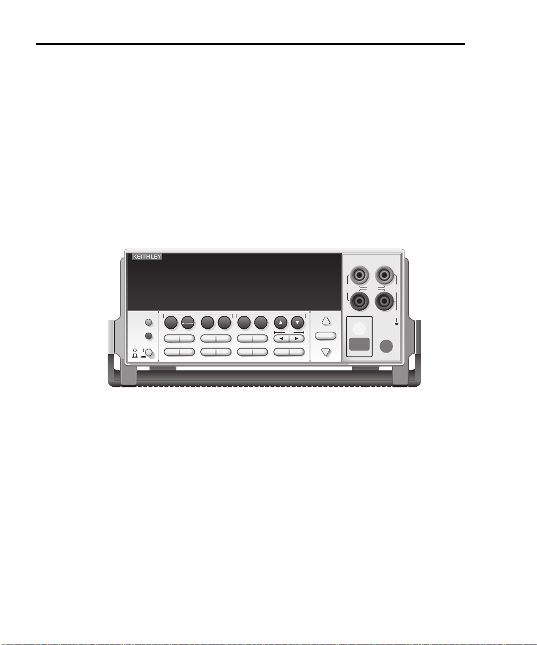
The front panel of the SourceMeter is shown in Figure 1-1. The following abbrevi-
ated information should be reviewed before operating the instrument.
Figure 1-1
SourceMeter front panel
Measurement (MEAS) function keys:
V Measure volts.
I Measure amps.
Ω Measure ohms.
FCTN Perform math functions.
SOURCE function keys:
V Source voltage (V-Source).
I Source current (I-Source).
∆ and ∇ Increase/decrease source or compliance value.
Operation keys:
EDIT Select source or compliance reading for editing.
TOGGLE Toggle display positions of source and measure readings, or display V and I
LOCAL Cancel remote operation.
REL Enable/disable relative reading on present function.
FILTER Display digital filter status for present function and toggle filter on/off.
LIMIT Perform configured limit tests.
TRIG Trigger a measurement from the front panel.
measurements.
Page 24

2400 Series SourceMeter® User’s Manual Getting Started 1-7
SWEEP Start configured sweep.
left/right arrows Move through parameter values or selections within functions and operations.
DIGITS Change number of digits of display resolution.
SPEED Change measurement speed by selecting accuracy or specifying NPLC.
STORE Set buffer size and enable reading storage.
RECALL Display stored readings and timestamp.
CONFIG Press CONFIG and then appropriate key to configure function or operation.
MENU Access and configure Main Menu selections. When entering numeric data, use to
EXIT Cancels selection. Use to back out of menu structures.
ENTER Accepts selection.
clear reading to minimum absolute value.
RANGE keys:
∆ Moves to next higher range, increments digit, moves to next selection.
∇ Moves to next lower range, decrements digit, moves to previous selection.
AUTO Enables or disables measurement auto range.
Annunciators:
EDIT Instrument in edit mode.
ERR Questionable reading, invalid cal step.
REM Instrument in GPIB remote mode.
TALK Instrument addressed to talk over GPIB.
LSTN Instrument addressed to listen over GPIB.
SRQ Service request over GPIB.
REAR Rear input/output connectors selected.
REL Relative measure reading displayed.
FILT Digital filter enabled.
MATH Math function enabled.
4W Remote sensing enabled.
AUTO Autoranging enabled.
ARM Source-measure operations being performed.
TRIG External trigger source selected.
* Reading being stored.
Input/output connectors:
INPUT/OUTPUT HI and LOUse to source-measure volts, amps, and ohms.
4-WIRE SENSE HI and LOUse for 4-wire remote sensing.
Input/output controls:
ON/OFF Turns the source on or off.
FRONT/REAR Selects front or rear panel input/output connections.
Handle:
Pull out and rotate to desired position.
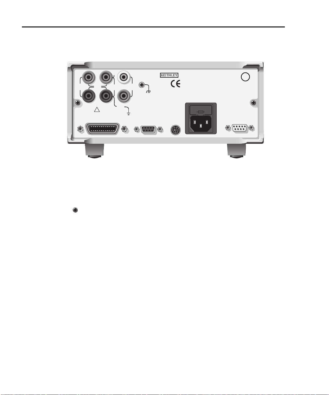
Rear panel summary
The rear panel of the Model 2400 SourceMeter is shown in Figure 1-2. (The Mod-
els 2410, 2420, 2425, 2430, and 2440 are similar.) The following abbreviated
information should be reviewed before operating the instrument.
NOTE Models 2420, 2425, 2430, and 2440 are not UL listed.
Page 25
1-8 Getting Started 2400 Series SourceMeter® User’s Manual
WARNING: NO INTERNAL OPERATOR SERVICABLE PARTS, SERVICE BY QUALIFIED PERSONNEL ONLY.
CAUTION: FOR CONTINUED PROTECTION AGAINST FIRE HAZARD, REPLACE FUSE WITH SAME TYPE AND RATING.
MADE IN
U.S.A.
INPUT/
OUTPUT
250V
PEAK
250V
PEAK
TRIGGER
LINK
4-WIRE
SENSE
HI
LO
LINE RATING
100-240VAC
50, 60, Hz
190VA MAX.
RS-232
IEEE-488
(ENTER IEEE ADDRESS
WITH FRONT PANEL MENU)
250V
PEAK
5V
PEAK
5V
PEAK
5V
PK
V, Ω,
GUARD
GUARD
SENSE
LINE FUSE
SLOWBLOW
2.5A, 250V
OUTPUT
ENABLE
FUSE DRAWER
L
U
CUS
LISTED
SourceMeter
4ZA4
CAT I
!
Figure 1-2
SourceMeter rear panel
Input/output connectors:
INPUT/OUTPUT HI and LOUse to source-measure volts, amps, and ohms.
4-WIRE SENSE HI and LOUse for 4-wire remote sensing.
V, Ω GUARD Driven guard for guarded measurements.
GUARD SENSE Use to correct for IR drops in Guard Output lead.
Earth (chassis) ground screw.
WARNING INPUT/OUTPUT LO is not internally connected to the chassis and
cannot be allowed to float more than the values shown in
Section 2 above chassis ground.
Output enable and digital input/output port:
OUTPUT ENABLEConnector for digital output lines, output enable, and component handler signals.
Power module:
Contains the AC line receptacle and the power line fuse.
Trigger link connector:
TRIGGER LINK 8-pin micro-DIN connector for sending and receiving trigger pulses. Use a trigger
link cable or adapter, such as Models 8501-1, 8501-2, 8502, 8504.
RS-232 connector:
RS-232 Connector for RS-232 remote operation. Use a straight through (not null modem)
GPIB connector:
DB-9 cable.
IEEE-488 Connector for GPIB remote operation. Use a shielded cable (Model
INTERFACE 7007-1 or 7007-2).
Figure 2-1 in
Page 26

2400 Series SourceMeter® User’s Manual Getting Started 1-9
Power-up
During the power-up, voltage spik es may appear on the terminals of
the SourceMeter. These voltage spikes could be at hazardous levels
(42.4V peak) and could damage sensitive DUTs. Never touch external
circuitry or the test leads when powering up the SourceMeter. It is good
practice to always disconnect DUTs from the SourceMeter before pow
ering up the unit.
To prevent electric shock, test connections must be configured such
that the user cannot come in contact with conductors or any DUT that
is in contact with the conductors. Safe installation requires proper
shields, barriers, and grounding to prevent contact with conductors.
Operator protection and safety are the responsibility of the person
installing the product.
When handling the SourceMeter, NEVER touch the heat sink located
on the left side of the case. This heat sink could be hot enough to cause
burns.
-
Line power connection
The SourceMeter operates from a line voltage in the range of 100 to 240V at a frequency of 50 or 60Hz. Line voltage and line frequency are automatically sensed.
Therefore, there are no switches to set. Check to be sure the operating voltage in
your area is compatible.
CAUTION Operating the instrument on an incorrect line voltage may cause
damage, possibly voiding the warranty.
Perform the following steps to connect the SourceMeter to line power and turn it
on:
1. Before plugging in the power cord, make sure the front panel power switch
is in the off (0) position.
2. Connect the female end of the supplied power cord to the AC receptacle on
the rear panel.
Page 27

1-10 Getting Started 2400 Series SourceMeter® User’s Manual
The power cord supplied with the SourceMeter contains a separate
ground for use with grounded outlets. When proper connections are
made, instrument chassis is connected to power line ground through
the ground wire in the power cord. Failure to use a grounded outlet
may result in personal injury or death due to electric shock.
3. Turn on the instrument by pressing the front panel power switch to the on
(1) position.
Power-up sequence
On power-up, the SourceMeter performs self-tests on its EPROM and RAM and
momentarily lights all segments and annunciators. If a failure is detected, the
instrument momentarily displays an error message, and the ERR annunciator
turns on (error messages are listed in Appendix B).
NOTE For the Model 2430, there is an internal bank of capacitors that need to
charge. While charging, the message “Charging capacitor bank, please
wait” message will be displayed for approximately 10 seconds.
If a problem develops while the instrument is under warranty, return it to
Keithley Instruments, Inc., for repair.
If the instrument passes the self-tests, the model number and the firmware revision levels are displayed. For example:
REV A01 A02
where: A01 is the main board ROM revision.
A02 is the display board ROM revision.
Also displayed is the line frequency. (If the wrong frequency is displayed, it can be
set manually as covered below). The communication interface status is briefly displayed. If the IEEE-488 bus is the presently selected interface, the identification
message will include the primary address. For example, if the primary address is
24 (factory default), the “IEEE Addr=24” message is displayed. If the RS-232
interface is selected, the “RS-232” message is displayed.
After the power-up sequence, the instrument goes to its normal display state with
the output off (OUTPUT indicator light off). With the output off, the “OFF” message
is displayed, and dashes replace the reading.
Page 28

2400 Series SourceMeter® User’s Manual Getting Started 1-11
Line frequency setting
At the factory, the SourceMeter is configured to sense the power line frequency
and automatically select the frequency setting. If, however, the line power source
is noisy, the SourceMeter may select the wrong setting on power-up. If this situation occurs, noisy measurement readings will result, and accuracy may be
affected. You can manually set the line frequency from the front panel MENU/ADCTRL/LINE-FREQ selection, or SYST:LFR by remote.
Fuse replacement
A rear panel fuse protects the power line input of the SourceMeter. If the line fuse
needs to be replaced, perform the following steps:
CAUTION For continued protection against fire or instrument damage, replace
the fuse only with the type and rating listed. If the instrument repeat
edly blows fuses, locate and correct the cause of the problem
before replacing the fuse.
1. The fuse is located in a drawer above the AC receptacle (Figure 1-2). At the
bottom of the fuse drawer is a small tab. At this location, use a small bladed
screwdriver to pry the fuse drawer open.
2. Slide the fuse drawer out to gain access to the fuse. Note that the fuse
drawer does not pull all the way out of the power module.
3. Snap the fuse out of the drawer and replace it with the same type
(
Appendix Table 1-1).
4. Push the fuse drawer back into the power module.
-
Table 1-1
Power line fuse
SourceMeter Fuse description Keithley part number
2400, 2400-LV,
2401, and 2410
2420, 2425, 2430,
and 2440
250V, 2.5A, 5 × 20mm FU-72
250V, 3.15A, 5 × 20mm FU-106-3.15
Page 29

1-12 Getting Started 2400 Series SourceMeter® User’s Manual
Cooling fan
The Models 2410, 2420, 2425, 2430, and 2440 use a cooling fan to help keep
them from overheating. The Models 2400 and 2401 do not have a cooling fan. In
either case (fan or no fan), proper ventilation must be maintained to prevent
overheating. Refer to the “WARNING - CAUTION” located at the beginning of
Section 3 for details on maintaining proper ventilation.
Model 2410 — Uses a constant-speed fan that runs continuously while the power
is on.
Models 2420, 2425, 2430, and 2440 — Uses a 3-speed fan. With the OUTPUT
ON, the fan speed setting is determined by the present current range (source or
measure).
2420, 2425, 2430, and 2440
range
10uA, 100uA, 1mA Low (50%)
10mA, 100mA Medium (75%)
1A, 3A, 3A/10A (2430) High (100%)
1A, 5A (2440) High (100%)
Fan speed
When the OUTPUT is turned OFF, the fan will either run at the low speed or stay
at the speed it was at when the output was on (current range dependent). This
speed option is set from the FAN selection of the GENERAL MENU. (See “Main
menu” in this section.)
NOTE If the Model 2420, 2425, 2430, or 2440 overheats, the output will trip and
the cooling fan will run at high speed (regardless of the speed option set
ting). See Section 6, “Overheating protection,” for details.
-
Page 30

2400 Series SourceMeter® User’s Manual Getting Started 1-13
Display
Display format
The SourceMeter display is used primarily to program source and compliance values and display measured readings. Annunciators, which are located along the
top of the reading/message display, indicate various states of operation, as covered previously in “Front panel summary.”
On power-up, the top (primary) display is used for measurements when the output
is on (with the output off, “OFF” is displayed). The bottom-left display is used for
the programmed source value (Vsrc or Isrc), and the bottom-right display is used
for the programmed compliance (Cmpl) limit.
Reading information can be displayed using either engineering units or scientific
notation in either fixed- or floating-point format. Use the GENERAL/NUMBERS
selection of the main MENU to select the display format, as discussed in “Menus”
later in this section.
Engineering units example: 1.23456µA
Scientific notation example: 1.23456e -6
NOTE The display may be disabled for faster operation. See “Disabling front
EDIT key
The SourceMeter must be in the edit mode to set source and compliance values.
The edit mode is selected by pressing the EDIT key (EDIT annunciator on). The
editing cursor (flashing digit) appears for the source or compliance reading. If a
value is not edited within six seconds, the edit mode is cancelled. While in the edit
mode, the EDIT key toggles between the source value and compliance value. See
Section 3 for details on setting source and compliance values.
TOGGLE key
NOTE For the Model 2430 Pulse Mode, the TOGGLE key is disabled.
With the output on, the TOGGLE key manipulates readings on the top display and
on the bottom-left display. It has no effect on the compliance reading (Cmpl),
which is located on the bottom right. Each press of the TOGGLE key sequences
through the display options.
panel display,” page 1-24.
Page 31

1-14 Getting Started 2400 Series SourceMeter® User’s Manual
With the voltage (V) or current (I) measurement function selected, the TOGGLE
key lets you display both the current and voltage measurements at the same time.
It also allows you to toggle display positions of the source and measure readings.
With the ohms (Ω) measurement function selected, the ohms measurement is
always displayed on the top display. The TOGGLE key lets you display either the
programmed source value, the current measurement, or the voltage
measurement on the bottom-left display.
The TOGGLE key is also used to display statistical data on readings stored in the
data store. This function is performed from the data store RECALL mode.
NOTE If FCTN, REL, or Limits is enabled, the TOGGLE key is disabled.
Status and error messages
Status and error messages are displayed momentarily. During SourceMeter operation and programming, you will encounter a number of front panel messages.
Typical messages are either status or error in nature and are listed in Appendix B.
Remote display programming
The display can also be controlled by various SCPI :DISPlay subsystem commands. See Section 18, “DISPlay subsystem,” for more information on using
these commands. See also “Disabling front panel display,” page 1-24.
Front panel tests
Use the TEST/FRONT-PANEL-TESTS selection of the main MENU to test various
aspects of the front panel. See “Menus,” page 1-19, for more information.
Page 32

2400 Series SourceMeter® User’s Manual Getting Started 1-15
Default settings
By using appropriate menu selections, you can save and recall various instrument
setups, define the power-on configuration, or restore factory defaults as outlined
below.
Saving and restoring user setups
You can save and restore up to five of your own user setups as covered below.
This feature provides a convenient way to save specific instrument configurations
and then recall them as needed. Note that you can also set up the SourceMeter to
restore a specific user setup at power-on. See “Power-on configuration,”
page 1-15.
NOTE There are two types of setups. Instrument configuration (user) setups
(covered here) and source memory sweep setups (
Saving setups
1. Select the various instrument operating modes you wish to save.
2. Press the MENU key, select SAVESETUP, then press ENTER.
3. From the SAVESETUP menu, select GLOBAL, then press ENTER.
4. From the GLOBAL SETUP MENU, select SAVE, then press ENTER.
5. Select the setup position (0-4) to save, then press ENTER to complete the
process.
Section 10).
Restoring setups
1. Press the MENU key, select SAVESETUP, then press ENTER.
2. From the SAVESETUP menu, select GLOBAL, then press ENTER.
3. From the GLOBAL SETUP MENU, select RESTORE, then press ENTER.
4. Select the setup position (0-4) to restore, then press ENTER to complete
the process.
Power-on configuration
You can also define which of the stored setups (factory default or user) the instrument assumes as the power-on configuration as follows:
1. Press the MENU key, select SAVESETUP, then press ENTER.
2. From the SAVESETUP menu, select GLOBAL, then press ENTER.
3. From the GLOBAL SETUP MENU, select POWERON, then press ENTER.
4. From the SET POWER-ON DEFAULT menu, choose the power-on configuration: BENCH or GPIB (see below), or USER-SETUP-NUMBER.
Page 33

1-16 Getting Started 2400 Series SourceMeter® User’s Manual
5. If you chose to use a user setup as the power-on configuration, select the
user setup number, then press ENTER.
Factory default settings
As summarized in Table 1-2, there are two sets of factory defaults, BENCH (front
panel) and GPIB (remote). You can restore either of these default conditions as
follows:
1. Press the MENU key, select SAVESETUP, then press ENTER.
2. From the SAVESETUP menu, select GLOBAL, then press ENTER.
3. From the GLOBAL SETUP MENU, select RESET, then press ENTER.
4. Select BENCH or GPIB defaults as desired, then press ENTER to complete
the process.
Table 1-2
Factory default settings
BENCH or GPIB
Setting
A/D Controls:
Auto-zero
Line frequency No effect
Beeper On
Contact check mode
Contact check threshold resistance
Contact check event detection
Contact check timeout
Data Store No effect
Digital output HI, HI, HI, HI
Digits 5
Fan (2420, 2425, 2430, and 2440) Output on
FCTN Power (off)
Filter: Off
Averaging type Repeat
Count
GPIB address No effect
Guard Cable
Limit tests:
DigOut:
Size 4-bit
Mode: Grading
Binning control Immediate
Auto clear: Disabled
Delay 0.00001 sec
On
Disabled**
50ohms**
Disabled**
0**
10
default
Page 34

2400 Series SourceMeter® User’s Manual Getting Started 1-17
Table 1-2 (cont.)
Factory default settings
Clear pattern 15**
H/W limits:
Control Disabled
Fail mode: In compliance
Cmpl pattern 15
S/W limits:
Lim 2, 3, 5-12:
Control Disabled
Low limit: -1.0
Low pattern 15
High limit: +1.0
High pattern 15
Pass (all tests):
Pass pattern 15
Source memory
Next
location
EOT mode EOT
Numbers No effect
Ohms source mode Auto
Offset compensated ohms Off
Output Off
Output enable Disabled
Off state Normal*
Auto-off Disabled
Power-on default No effect
Pulse Mode (2430 only)
Pulse delay 0.0s
Pulse width 0.20ms
Ranging (measure):
Auto range Enabled
Rel Off
Value 0.0
RS-232 No effect
Sense mode 2-wire
Source delay 1ms
Auto-delay Enabled
Source shape (2430 only): DC mode
Speed Normal (1 PLC)
Sweep Linear staircase
Start 0V or 0A
Stop 0V or 0A
Step 0V or 0A
Sweep count 1
Sweep Pts 2500
Source ranging Best fixed
Abort on compliance Off
Page 35

1-18 Getting Started 2400 Series SourceMeter® User’s Manual
Table 1-2 (cont.)
Factory default settings
Voltage protection NONE
Triggered source:
Control Disabled
Scale factor +1.0
Triggering:
Arm layer:
Event Immediate
Count 1
Output trigger Line #2, Off
Trigger layer:
Event Immediate
Count 1
Output triggers Line #2, All off
Delay 0.0 sec
* Model 2410 default off state is guard.
** For instruments with contact check option (denoted by a -C in model number).
Remote setups
You can also save and recall setups via remote using the following SCPI commands:
• Save and recall user setups using *SAV and *RCL (Section 16).
• Restore GPIB defaults using *RST (Section 16).
• Restore bench defaults using :SYSTem:PRESet (Section 18).
• Save the power-on configuration using :SYSTem:POSetup (Section 18).
Page 36

2400 Series SourceMeter® User’s Manual Getting Started 1-19
Menus
The following paragraphs discuss the main menu, configuration menus, and rules
to navigate menus.
Main menu
Use the MENU key to access the Main Menu to select, configure, and/or perform
various instrument operations. The overall Main Menu structure is summarized in
Table 1-3. Use the “Rules to navigate menus” to check and/or change Main Menu
options.
Page 37

1-20 Getting Started 2400 Series SourceMeter® User’s Manual
Table 1-3
Main menu
Menu item
1
Description Parameters
SAVESETUP
GLOBAL
SAVE
RESTORE
POWERON
BENCH
GPIB
USER SETUP NUMBER
RESET
SOURCE MEMORY
SAVE
RESTORE
COMMUNICATION
GPIB
RS-232
BAUD
BITS
PAR ITY
TERMINATOR
FLOW CTRL
3
CAL
UNLOCK
EXECUTE
VIEW DATES
SAVE
LOCK
CHANGE PASSWORD
TEST
DISPLAY TESTS
4
KEYS
DISPLAY PATTERNS
CHAR SET
Configure setup conditions.
Control instrument settings.
Save present SourceMeter setup to memory location.
Return the SourceMeter to setup saved in memory.
0 to 4
0 to 4
Select the power-on default setup.
Powers-on to BENCH defaults.
Powers-on to GPIB defaults.
Powers-on to user setup.
Returns unit to BENCH or GPIB defaults.
See Table 1-2
See Table 1-2
0 to 4
See Table 1-2
Control memory sweep source setup configurations.
Save present setup configuration to memory location.
2
Return to configuration saved in memory location.
Select and configure remote interface.
Select GPIB (IEEE-488 Bus), set primary address and
GPIB protocol.
1 to 100
1 to 100
0 to 30
(Default: 24)
Select the RS-232 interface, set parameters.
Select baud rate.
57600, 38400,
19200, 9600,
4800, 2400,
1200, 600, 300
Select number of data bits.
Select parity.
7 or 8
NONE, ODD,
EVEN
Select terminator.
CR, CR+LF, LF,
or LF+CR
Select flow control.
NONE or
XON/XOFF
Calibrate SourceMeter. (See Service Manual.)
Unlock calibration.
Execute calibration steps.
Display cal dates and count.
Save calibration constants.
Lock calibration.
Change calibration password.
Perform tests on SourceMeter.
Test front panel keys and display digits.
Test front panel keys.
Test display pixels and annunciators.
Test special display characters.
Page 38

2400 Series SourceMeter® User’s Manual Getting Started 1-21
Table 1-3 (cont.)
Main menu
Menu item
1
Description Parameters
A/D CTRL
AUTO ZERO
DISABLE
ENABLE
ONCE
LINE FREQ
NPLC CACHE
DISABLE
ENABLE
REFRESH
RESET
GENERAL
DIGOUT
SERIAL#
5
Control auto-zero, line frequency, NPLC caching.
Control auto zero.
Disable auto zero.
Enable auto zero.
Force auto zero immediate update.
Set line frequency.
Control NPLC caching.
Disable NPLC caching.
Enable NPLC caching.
Update all NPLC values in cache immediately.
Clear NPLC cache of all NPLC values.
Select general operations.
Set Digital I/O port bit pattern.
Display serial number, firmware revision, SCPI
50 or 60Hz, or
AUTO
6
0-15
YES or NO
version.
TIMESTAMP
FAN (2420, 2425, 2430, and
2440)
Reset timestamp.
Set fan speed control. ALWAYS — fan runs at the
same speed with the output on or off. OUTPUT
ALWAYS or
OUTPUT ON
ON — fan runs at low speed with the output off.
See “Cooling fan,” page 1-12.
NUMBERS
BEEPER
Select engineering units or scientific notation display
format.
Enable or disable beeper.
ENGR,
SCIENTIFIC
1. Top level menu choices indicated in bold. Indentation identifies each lower submenu level.
2. When the remote operation interface selection (GPIB or RS-232) is changed, the SourceMeter performs a power-on reset. To check or change options of the selected interface, you must re-enter the
menu structure.
3. Only VIEW DATES is accessible when calibration is locked. Password is required to unlock calibration.
4. Press EXIT key to cancel test.
5. Disabling auto zero will reduce measurement accuracy.
6. 0-65535 with 2499-DIGIO 16-bit option.
Page 39

1-22 Getting Started 2400 Series SourceMeter® User’s Manual
Rules to navigate menus
Many source-measure functions and operations are configured from the front
panel menus. Use the following rules to navigate through these configuration
menus:
NOTE Complete rules to edit source and compliance values are found in the
Basic source-measure procedure in
compliance values” below for an overview.
• A menu item is selected by placing the cursor on it and pressing ENTER.
Cursor position is denoted by the blinking menu item or option. The EDIT
and
∇ keys control cursor position.
• A displayed arrow on the bottom line indicates there are one or more additional items (or messages) to select from. Use the appropriate cursor key to
display them.
• A source or parameter value range is changed by placing the cursor on the
range designator (i.e., k, M, G, etc.) and using the SOURCE
RANGE
is selected, the reading increases or decreases by a decade.
• A parameter value is keyed in by placing the cursor on the digit to be
changed and using one of the following methods:
∆ or ∇ keys. Note that when the next higher or lower source range
Section 3. See “Editing source and
∆
∆ or ∇ or
NOTE You can clear a parameter value by pressing the MENU key.
– Use the SOURCE ∆ or ∇ or RANGE ∆ or ∇ keys to increment or dec-
rement the digit.
– Use the number keys (0 through 9) to key in the value at the selected
digit.
– Use the ± key to change source value polarity, regardless of cursor
position.
• Boolean selections (such as ON/OFF and HIGH/LOW) are toggled by placing the cursor on the selection and pressing a SOURCE or RANGE up or
down arrow key.
• A change is only executed when ENTER is pressed. Entering an invalid
parameter generates an error, and the entry is ignored. However, entering
an out-of-range value (too small or too large) selects the lower or upper
limit, respectively.
• The EXIT key is used to back out of the menu structure. Any change that is
not entered is cancelled when EXIT is pressed.
Page 40

2400 Series SourceMeter® User’s Manual Getting Started 1-23
Editing source and compliance values
Use the following keys to edit source and compliance values:
• EDIT — selects the source or compliance display field for editing. A blinking
cursor will appear in the field to be edited. If no key is pressed within a few
seconds, the edit mode will be cancelled automatically.
• EDIT arrow keys — places the display cursor on the display digit to be
changed.
• SOURCE ∆ or ∇— increments or decrements the source or compliance
value. Note that pressing either of these keys will automatically enable the
source edit mode.
•RANGE ∆ or ∇
• Numeric keys (0-9) — allow you to directly enter source or compliance values.
• EXIT — exits the edit mode without waiting for the time-out period.
The basic procedure for editing source and compliance values is outlined below.
See Section 3, “Basic source-measure procedure,” for more details.
1. Press the EDIT key until the blinking cursor is in either the source or compliance display field to be edited.
2. If desired, use the RANGE ∆ or ∇ key to select the desired source or compliance range.
3. To simply increment or decrement the display value, use the EDIT arrow
keys to place the blinking cursor on the digit to be changed, then increment
or decrement the value with the SOURCE
source or compliance value will be updated immediately; you need not
press ENTER to complete the process.
4. To enter the source or compliance value directly, simply key in the desired
value with the numeric keys while the cursor is blinking. Again, the source
or compliance value will be updated immediately.
— selects the source or compliance range.
∆ or ∇ keys. Note that the
Toggling the source and measure display fields
Normally, the measured reading value will appear in the upper, main display line,
while the source and compliance values appear in the left and right fields respectively of the lower display line. You can toggle the source and measure display
fields by pressing the TOGGLE key to place the source and measure values in the
desired positions.
Page 41

Disabling front panel display
Front panel display circuitry can be disabled to allow the instrument to operate at
a higher speed. While disabled, the display is frozen with the following message:
FRONT PANEL DISABLED
Press LOCAL to resume.
As reported by the message, all front panel controls (except LOCAL, TRIG, and
OUTPUT ON/OFF) are disabled.
Front panel control
Front panel display circuitry is controlled from the DISABLE DISPLAY configuration menu, which is accessed by pressing CONFIG and then EDIT (or TOGGLE).
To select an option (NOW, NEVER, SWEEP, or STORE), use the EDIT cursor
keys to place the cursor on the desired option, then press ENTER.
The options for DISABLE DISPLAY are explained as follows:
NOW — Select this option to disable the display now.
NEVER — Select this option if you do not want the display to disable.
SWEEP — Select this option if you want the display to disable while performing a
sweep. The display will disable as soon as sweep is started. The display will automatically re-enable after the sweep is completed.
STORE — Select this option if you want the display to disable when storing
source- measure readings in the buffer. The display will disable as soon as the
buffer is enabled. The display will automatically re-enable after the storage process is completed. Note that with this option, the display will disable while performing a sweep. Sweep readings are automatically stored in the buffer.
Remote command programming
Use the following SCPI commands to enable or disable the front panel display circuitry:
:DISPlay:ENABle OFF Disable the display
:DISPlay:ENABle ON Enable the display
Configuration menus
There are a number of configuration menus that can be accessed by pressing the
CONFIG key followed by the appropriate function or mode key. For example, you
can configure the voltage source by pressing CONFIG then SOURCE V. Configuration menus are available for the following operating modes:
• Measure functions (V, Ω, FCTN):
Page 42

2400 Series SourceMeter® User’s Manual Getting Started 1-25
• SOURCE V, SOURCE I, and RANGE:
• REL, FILTER, and LIMIT:
•TRIG:
• SWEEP, DIGITS, SPEED, and STORE:
• ON/OFF OUTPUT and Display (EDIT or TOGGLE):
Page 43

2
Connections
• Connection overview — Discusses front/rear terminal selection and using
output enable.
• Connections to DUT — Covers various methods for making connections
to the DUT, including 4-wire remote sensing, 2-wire local sensing, cable
and ohms guard, as well as sense and guard selections.
Page 44

2-2 Connections 2400 Series SourceMeter® User’s Manual
Connection overview
WARNING To prevent electric shock, test connections must be configured
such that the user cannot come in contact with conductors or
any DUT that is in contact with the conductors. Safe installa
tion requires proper shields, barriers, and grounding to prevent contact with conductors. Operator protection and safety
are the responsibility of the person installing the product.
During power-up, voltage spikes may appear on the terminals
of the SourceMeter. These voltage spikes could be at hazard
ous levels (42.4V peak) and could damage sensitive DUTs.
Never touch external circuitry or the test leads when powering
up the SourceMeter. It is good practice to always disconnect
DUTs from the SourceMeter before powering up the SourceMe
ter.
Hazardous voltages may be present on the output and guard
terminals. To prevent electrical shock that could cause injury
or death. NEVER make or break connections to the SourceMe
ter while the unit is on. Power off the equipment from the front
panel or disconnect the main power cord from the rear of the
SourceMeter before handling cables connected to the outputs.
Putting the equipment into standby mode does not guarantee
the outputs are not powered if a hardware or software fault
occurs.
-
-
-
-
Front/rear terminals selection
The OUTPUT (HI and LO) and SENSE (HI and LO) terminals are accessible from
both the front and rear panels. The GUARD, GUARD SENSE, and EARTH (chassis ground) terminals are only accessible from the rear panel.
Front panel terminals selection
The FRONT/REAR TERMINALS key is used to control which set of terminals is
connected to the SourceMeter. Pressing this key toggles the SourceMeter connections between the front and rear terminals. When the REAR annunciator is on,
the rear terminals are connected to the SourceMeter. When REAR is off, the front
terminals are selected.
NOTE When the FRONT/REAR TERMINALS key is pressed, the OUTPUT will
turn OFF.
Page 45

2400 Series SourceMeter® User’s Manual Connections 2-3
Remote command terminals selection
Use the :ROUTe:TERMinals (Section 18) command to select the front or rear
panel terminals via remote.
Test fixture output enable
A test fixture switch can be used with the SourceMeter to help protect the DUT.
The SourceMeter output will turn off when the lid of the test fixture is opened.
However, you must ALWAYS assume that power is present until you verify that
the SourceMeter output is off. See Section 13 for details.
Connections to DUT
The maximum allowable voltage differentials between terminals are labeled on
the SourceMeter. Figure 2-1 shows these voltage differentials for the various
SourceMeter models.
WARNING To prevent electric shock and/or damage to the SourceMeter,
DO NOT exceed the maximum allowable voltage differentials
shown in
Figure 2-1.
The front and rear terminals of the SourceMeters are rated for
connection to circuits rated Installation Category I only. Do not
connect the SourceMeter terminals to CAT II, CAT III, or CAT IV
circuits. Connections of the SourceMeter Input/Output termi
nals to circuits higher than CAT I can cause damage to the
equipment or expose the operator to hazardous voltages.
Common mode current limits — As shown in Figure 2-1, the maximum common
mode voltage is the voltage between INPUT/OUTPUT LO and chassis ground. In
order to prevent electric shock and/or damage to the SourceMeter, current from
an external common mode voltage source must be limited. Current limiting can be
accomplished with the use of a protective impedance or a fuse.
-
Page 46

2-4 Connections 2400 Series SourceMeter® User’s Manual
INPUT/
OUTPUT
250V
PEAK
250V
PEAK
4-WIRE
SENSE
HI
LO
250V
PEAK
5V
PEAK
5V
PEAK
5V
PK
V, W
GUARD
GUARD
SENSE
WARNING:
NO INTERNAL OPERATO
CAT
I
Model 2400, 2400-C
!
INPUT/
OUTPUT
250V
PEAK
50V
PEAK
4-WIRE
SENSE
HI
LO
50V
PEAK
5V
PEAK
5V
PEAK
5V
PK
V, W
GUARD
GUARD
SENSE
WARNING:
NO INTERNAL OPERAT
Model 2401
!
INPUT/
OUTPUT
250V
PEAK
125V
PEAK
4-WIRE
SENSE
HI
LO
125V
PEAK
5V
PEAK
5V
PEAK
5V
PK
V, W
GUARD
GUARD
SENSE
WARNING:
NO INTERNAL OPERAT
Model 2425, 2425-C, 2430, 2430-C
INPUT/
OUTPUT
250V
PEAK
75V
PEAK
4-WIRE
SENSE
HI
LO
75V
PEAK
5V
PEAK
5V
PEAK
5V
PK
V, W
GUARD
GUARD
SENSE
WARNING:
NO INTERNAL OPERAT
Model 2420, 2420-C
INPUT/
OUTPUT
40V
PEAK
52V
PEAK
4-WIRE
SENSE
HI
LO
42V
PEAK
5V
PEAK
5V
PEAK
5V
PK
V, W
GUARD
GUARD
SENSE
WARNING:
NO INTERNAL OPERAT
Model 2440, 2440-C
INPUT/
OUTPUT
250V
PEAK
1100V
PEAK
4-WIRE
SENSE
HI
LO
1100V
PEAK
5V
PEAK
5V
PEAK
5V
PK
V, W
GUARD
GUARD
SENSE
WARNING:
NO INTERNAL OPERATO
CAT
I
Model 2410, 2410-C
!
WARNING To prevent electric shock and/or damage to the SourceMeter,
common mode voltage must be externally limited as follows:
Models 2400, 2400-LV, 2401, and 2410 — Limit common mode
voltage to 250VDC, 1.05A maximum
Models 2420 and 2425 — Limit common mode voltage to
250VDC, 3.15A maximum
Model 2430 — Limit common mode voltage to 250VDC, 10.5A
(pulse)
Model 2440 — Limit common mode voltage to 40VDC, 5.25A
maximum
Figure 2-1
Terminal voltage differentials (rear panel)
Page 47

2400 Series SourceMeter® User’s Manual Connections 2-5
NOTE To avoid redundancy, generic SourceMeter drawings will be used in this
section. A generic drawing excludes the labeling for the terminal voltage
differentials.
Sensing methods
Basic source-measure operations are performed using either 2-wire local sense
connections (Figure 2-2) or 4-wire remote sense connections (Figure 2-3). The
factory default sense selection is local. See “Sense selection,” page 2-12, to
check and/or change the sense selection. Also, see Section 4 for “Ohms sensing”
issues.
WARNING There is no internal connection between earth ground and the
selected INPUT/OUTPUT LO terminal of the SourceMeter.
Therefore, hazardous voltages (>30V rms) can appear on that
LO terminal. Typically, this can occur when the SourceMeter is
operating in any mode where the output changes rapidly, such
as quick, pulsed waveforms that can be generated using the
ZERO, AUTO-OFF output state, or fast pulse sweep operations.
To prevent this from occurring (if your application allows it),
connect the INPUT/OUTPUT LO terminal to earth ground. You
can connect the LO terminal to the chassis ground screw ter
minal on the rear panel, or to a known safety earth ground.
Note that the front panel terminals are isolated from the rear
panel terminals. Therefore, if you are using the front panel ter
minals, ground the front panel LO terminal. If using the rear
panel terminals, ground the rear panel LO terminal.
-
-
Page 48
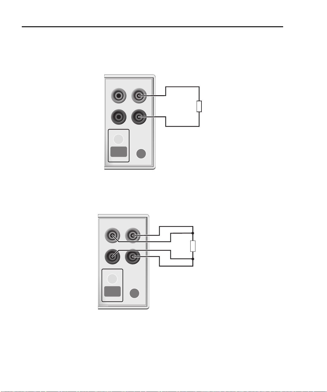
2-6 Connections 2400 Series SourceMeter® User’s Manual
HI
LO
OUTPUT
INPUT/
OUTPUT
4-WIRE
SENSE
ON/OFF
TERMINALS
FRONT/
REAR
DUT
SourceMeter Front Panel
Sense Selection: 2-wire
FRONT/
REAR
HI
LO
OUTPUT
INPUT/
OUTPUT
4-WIRE
SENSE
ON/OFF
TERMINALS
FRONT/
REAR
DUT
SourceMeter Front Panel Sense Selection: 4-wire
FRONT/
REAR
Figure 2-2
Two-wire connections (local sense)
Figure 2-3
Four-wire connections (remote sense)
NOTE Connections alone do not determine sense mode. For local sensing (Fig-
ure 2-2), 2-wire sensing must be selected from the SENSE MODE option
of the CONFIGURE V-SOURCE menu. For remote sensing (Figure 2-3),
4-wire
Page 49

2400 Series SourceMeter® User’s Manual Connections 2-7
sensing must be selected. The 2-wire sense mode is the BENCH and
GPIB default. See
“Sense selection,” page 2-12, for details.
4-wire remote sensing
When sourcing and/or measuring voltage, there can be errors associated with IR
drops in the test leads. Voltage source and measure accuracy are optimized by
using 4-wire remote sense connections. When sourcing voltage, 4-wire remote
sensing ensures that the programmed voltage is delivered to the DUT. When
measuring voltage, only the voltage drop across the DUT is measured. Use 4-wire
remote sensing for the following source-measure conditions:
• Test circuit impedance is <1kΩ.
• Optimum Ohms, V-Source, and/or V-Measure accuracy are required.
NOTE Specified accuracies for both source and measure are only achieved using
4-wire remote sensing.
WARNING When sourcing voltage in remote sense, make sure the sense
leads are connected to the DUT. If a sense lead becomes dis
connected, 0V will be sensed, and the SourceMeter will
increase the output voltage (to possibly hazardous levels) to
compensate. For increased safety, you can limit the voltage
output by the SourceMeter. See
tion,” to limit the output voltage level.
Section 3, “V-source protec-
-
NOTE When the output is turned off in the 4-wire sense mode, the sense lines
are internally disconnected for safety reasons. The sense lines are auto
matically reconnected when the output is turned on, and 4-wire sensing is
restored.
-
2-wire local sensing
2-wire local sense connections can only be used if the error contributed by test
lead IR drop is acceptable to the user. At current levels below 100mA, the errors
are usually not significant (assuming test lead resistance is not greater than 1Ω).
Since current in a series circuit is the same at all points in the loop, remote sensing does not improve I-Source or I-Measure accuracy. Thus, if sourcing current
and measuring current, you can use local sensing. Other conditions that allow the
use of 2-wire local sensing include:
• Test circuit impedance is 1kΩ. Above 1GΩ, guarding should also be used
(“Cable guard”).
• Measure Only (V or I) operation.
Page 50

2-8 Connections 2400 Series SourceMeter® User’s Manual
Guarding methods
Cable guard
Use the high-impedance (cable) guard connection scheme shown in Figure 2-4
for the following source-measure condition:
• Test circuit impedance is >1GΩ.
Note that cable guard must be selected for this connection scheme. See “Guard
selection,” page 2-13, to select cable guard.
A test fixture is typically used when testing high-impedance devices. The test fixture reduces noise and protects the user from a potentially hazardous voltage on
the guard shield (or plate). See Section 6, “Guard,” for details on using guard.
Note that the test fixture chassis is connected to In/Out LO to reduce noise.
Page 51

2400 Series SourceMeter® User’s Manual Connections 2-9
INPUT/
OUTPUT
4-WIRE
SENSE
HI
LO
IEEE-488
(ENTER IEEE ADDRESS
WITH FRONT PANEL MENU)
V, Ω
GUARD
GUARD
SENSE
WARNING: NO INTERNAL OPERATOR SERVICA
CAUTION: FOR CONTINUED PROTECTION AGAINST FIR
RS232
DUT
Connect to earth safety ground
using #18 AWG wire or larger.
Guard Shield Test Fixture
Figure 2-4
High-impedance guarding (cable guard)
Ohms guard
Use the guarded ohms connection schemes shown in Figure 2-5 for the following
source-measure operation:
• In-circuit resistance measurements on the DUT where other parasitic leakage devices are present.
Note that ohms guard must be selected for this connection scheme. Ohms guard
is not available for the 1A range (source or measure). See “Guard selection,”
page 2-13, to select ohms guard and Section 4, “6-wire ohms measurements.”
Page 52

2-10 Connections 2400 Series SourceMeter® User’s Manual
Figure 2-5 shows how to make connections to measure the resistance of a single
resistor (DUT) in a resistor network. See Section 6, “Guard,” for more information
on guarded ohms measurements.
The basic connection scheme for guarded ohms measurements is shown in Fig-
ure 2-5A. If the guard resistance path (R
<1kΩ, IR drop in the GUARD test
G) is
lead could be high enough that the guard voltage at the resistor network is significantly less than the output voltage at the DUT. This results in leakage current and
will corrupt the measurement. To cancel the effect of IR drop in the GUARD test
lead, connect GUARD SENSE to the resistor network as shown in Figure 2-5B.
Guard sense ensures that the guard voltage at the resistor network is the same as
the output voltage at the DUT.
Note that if the DUT is <1kΩ, you should use the 4-wire measurement method
(remote sensing) by connecting SENSE HI and LO to the DUT and enabling remote
sense (Figure 2-5C).
NOTE Guard current (IG) must never exceed 50mA. If it does, guard voltage will
become less than the output voltage and corrupt the measurement.
Page 53

2400 Series SourceMeter® User’s Manual Connections 2-11
WARNING: NO INTERNAL OPERAT OR SER VICAB
CAUTION: FOR CONTINUED PROTECTION AGAINST FIR
HI
LO
IEEE-488
(ENTER IEEE ADDRESS
WITH FRONT PANEL
WARNING: NO INTERNAL OPERATOR SERVICA
CAUTION: FOR CONTINUED PRO TECTION AGAINST FIR
INPUT/
OUTPUT
4-WIRE
SENSE
HI
LO
IEEE-488
(ENTER IEEE ADDRESS
WITH FRONT PANEL MENU)
V, Ω
GUARD
GUARD
SENSE
RS232
INPUT/
OUTPUT
4-WIRE
SENSE
HI
LO
IEEE-488
(ENTER IEEE ADDRESS
WITH FRONT PANEL MENU)
V, Ω
GUARD
GUARD
SENSE
WARNING: NO INTERNAL OPERATOR SERVICA
CAUTION: FOR CONTINUED PRO TECTION AGAINST FIR
RS232
RS232
R
G
≥1kΩ
I
G
Resistor Network
Sense Selection: 2-wire (local)
A. Basic connections
R
G
<1kΩ
Resistor Network
Sense Selection: 2-wire (local)
B. Connections using guard sense
!
!
DUT
V, Ω
GUARD
4-WIRE
SENSE
INPUT/
OUTPUT
GUARD
SENSE
C. 6-wire ohms connections
I
G
Figure 2-5
Guarded ohms measurements (ohms guard)
Page 54

2-12 Connections 2400 Series SourceMeter® User’s Manual
Sense and guard selections
NOTE When sense or guard settings are changed, the OUTPUT will turn OFF.
Sense selection
When using the SENSE HI and LO terminals of the SourceMeter, 4-wire remote
sensing must be selected. When not using these terminals, local sensing must be
selected. Sense selection is explained as follows. See Section 3, “Operation over-
view,” for details on sense.
NOTE The SourceMeter defaults to the 2-wire (local) sense mode when the out-
put is off, regardless of the sense setting. When the output is turned on,
the present sense setting will be in effect.
Front panel sense selection
On power-up, the instrument is automatically set for 2-wire local sense. Perform
the following steps to check and/or change the sense selection:
1. Press CONFIG and then the SOURCE V, MEAS V, or Ω key. Changing
sense in one configuration menu changes it in all of the others.
2. For SOURCE V and Ω, use the ß and © keys to place the cursor (flashing
menu item) on SENSE MODE and press ENTER.
NOTE Cursor position indicates the present sense selection. Two-wire indicates
that local sense is selected, and 4-wire indicates that remote sense is
selected. To retain the present selection, use the EXIT key to back out of
the menu structure and skip the next two steps.
3. To change the sense selection, place the cursor on 4-wire to select remote
sense or on 2-wire to select local sense, and press ENTER.
4. Use the EXIT key to back out of the menu structure.
Remote command sense selection
Use the :SYSTem:RSENse command (Section 18, “SYSTem subsystem”) to
choose between local and remote sensing via remote. For example, send the following command to enable remote sensing:
:SYST:RSEN ON
Conversely, send this command to disable remote sensing (enable local sensing):
:SYST:RSEN OFF
Page 55

2400 Series SourceMeter® User’s Manual Connections 2-13
Guard selection
Cable guard is used for high-impedance guarding for cables (i.e., coax and triax)
and test fixtures. Ohms guard provides a high-current guard output, which allows
in-circuit guarded ohms measurements. On power-up, cable guard is selected.
NOTE For 6-wire ohms measurements, use the guard output off mode. See
Section 13, “Front panel output configuration,” for details on the various
output off states and how to select the guard output off state. See also
Section 4, “6-wire ohms measurements.”
Front panel guard selection
Perform the following steps to check or change the guard selection:
1. Press CONFIG and then SOURCE V, SOURCE I, or Ω. Changing guard in
one configuration menu changes it in all of the others.
2. Using the SOURCE arrow keys, place the cursor (flashing menu item) on
GUARD and press ENTER.
NOTE Cursor position indicates the present guard selection (OHMS or CABLE).
To retain the present selection, use the EXIT key to back out of the menu
structure and skip the next two steps.
3. To change the guard selection, place the cursor on the alternate selection
and press ENTER.
4. Use the EXIT key to back out of the menu structure.
NOTE Do not use ohms guard with coaxial cabling, or oscillations may occur.
Ohms guard cannot be selected on the 1A or higher range (source or
measure).
Remote command guard selection
Use the :SYSTem:GUARd command (Section 18, “SYSTem subsystem”) to
choose between cable and ohms guard mode via remote. For example, send the
following command to enable ohms guard:
:SYST:GUAR OHMS
Conversely, send this command to enable cable guard:
:SYST:GUAR CABL
Page 56

3
Basic Source-Measure Operation
• Operation overview — Discusses source-measure capabilities, compliance limit, and fundamental source-measure configuration.
• Operation considerations — Covers warm-up, auto zero, V-source protection, and source delay.
• Basic source-measure procedure — Describes the basic procedure for
setting up the SourceMeter for source-measure operations, including
selecting the source function, output values, and compliance limits; choos
ing measurement range and function; and turning the output on and off.
• Measure only — Covers how to use the SourceMeter for measurements
only.
• Sink operation — Describes sink operation.
-
Page 57

3-2 Basic Source-Measure Operation 2400 Series SourceMeter® User’s Manual
WARNING - CAUTION
The SourceMeter uses a heat sink to dissipate heat. Also, the Models 2410, 2420,
2430, and 2440 have a cooling fan. The left side of the case is cut out to expose
the black, finned heat sink. This heat sink gets hot and could be hot enough to
cause burns. Even if the instrument is turned off, you should assume that the heat
sink is still hot as it takes considerable time for it to cool off.
WARNING When handling the SourceMeter, NEVER touch the heat sink
located on the left side of the case. This heat sink could be hot
enough to cause burns.
NOTE See Section 1, “Cooling fan,” for operation details on the cooling fan.
Excessive heat could damage the SourceMeter and at the very least, degrade its
performance. The SourceMeter must be operated in an environment where the
ambient temperature does not exceed 50°C.
CAUTION To prevent damaging heat build-up, and thus ensure specified
performance, adhere to the following precautions:
• Keep the heat sink free of dust, dirt, and contaminates, since its
ability to dissipate heat could become impaired.
• Keep the bottom cooling vents from becoming blocked. NEVER
remove the plastic feet and place the SourceMeter directly on a
flat surface. NEVER operate the SourceMeter when it is sitting
on a conformable surface (such as a carpet). This could block
the bottom cooling vents.
• Do not position any devices adjacent to the SourceMeter that
force air (heated or unheated) into or onto its surfaces or cool
ing vents. This additional airflow could compromise accuracy
performance.
• When rack mounting the SourceMeter, make sure there is ade-
quate airflow around the bottom and sides to ensure proper
cooling. Adequate airflow enables air temperatures within
approximately one inch of the SourceMeter surfaces to remain
within specified limits under all operating conditions.
• Rack mounting high power dissipation equipment adjacent to
the SourceMeter could cause excessive heating to occur. The
specified ambient temperatures must be maintained around the
surfaces of the SourceMeter to specified accuracies.
-
Page 58

2400 Series SourceMeter® User’s Manual Basic Source-Measure Operation 3-3
• A good measure to ensure proper cooling in rack situations with
convection cooling only is to place the hottest equipment (i.e.,
power supply) at the top of the rack. Precision equipment, such
as the SourceMeter, should be placed as low as possible in the
rack where temperatures are the coolest. Adding spacer panels
below the SourceMeter will help ensure adequate air flow.
Page 59

3-4 Basic Source-Measure Operation 2400 Series SourceMeter® User’s Manual
Operation overview
Source-measure capabilities
From the front panel, the SourceMeter can be configured to perform the following
operations:
• Source voltage — Display current and/or voltage measurement
• Source current — Display voltage and/or current measurement
• Measure resistance — Display voltage or current component of measurement
• Measure only (V or I) — Display voltage or current measurement
Voltage and Current — Table 3-1 lists the source and measure limits for the volt-
age and current functions.
The full range of operation is explained in Section 6, “Overheating protection” and
“Operating boundaries.”
NOTE Output transient recovery — The time required for the V-source to
recover to its original value (within 0.1% plus load regulation errors) after
a step change in load current is <250µsec. This does not include the
response time of autoranging or the second order effects on loads that
are not purely resistive.
Load regulation — The voltage specification for V-source mode load
changes is 0.01% +1mV. This means that on the 200mV range, the load
current can be changed from zero to full scale with less than 1.02mV of
error. Calculation:
error = (0.01% x 0.2V) + 1mV = 1.02mV
Assuming a 0 to 1A change in current, the output impedance equates to
1.02m
Ω
(1.02mV/1A = 1.02mΩ). This level can only be achieved using 4-
wire remote sensing.
Page 60

2400 Series SourceMeter® User’s Manual Basic Source-Measure Operation 3-5
Table 3-1
Source-measure capabilities
2400/2400-LV/2401 2410
Range Source Measure Range Source Measure
200mV
2V
20V
200V*
1µA
10µA
100µA
1mA
10mA
100mA
1A
±210mV
±2.1V
±21V
±210V
±1.05µA
±10.5µA
±105µA
±1.05mA
±10.5mA
±105mA
±1.05A
±211mV
±2.11V
±21.1V
±211V
±1.055µA
±10.55µA
±105.5µA
±1.055mA
±10.55mA
±105.5mA
±1.055A
200mV
2V
20V
1000V
1µA
10µA
100µA
1mA
20mA
100mA
1A
±210mV
±2.1V
±21V
±1.1kV
±1.05µA
±10.5µA
±105µA
±1.05mA
±21mA
±105mA
±1.05A
±211mV
±2.11V
±21.1V
±1.1kV
±1.055µA
±10.55µA
±105.5µA
±1.055mA
±21.1mA
±105.5mA
±1.055A
(*2400 only) Max Power = 22W Max Power = 22W
2420 2425/2430
Range Source Measure Range Source Measure
200mV
2V
20V
60V
10µA
100µA
1mA
10mA
100mA
1A
3A
±210mV
±2.1V
±21V
±63V
±10.5µA
±105µA
±1.05mA
±10.5mA
±105mA
±1.05A
±3.15A
±211mV
±2.11V
±21.1V
±63.3V
±10.55µA
±105.5µA
±1.055mA
±10.55mA
±105.5mA
±1.055A
±3.165A
200mV
2V
20V
100V
10µA
100µA
1mA
10mA
100mA
1A
3A/10A
±210mV
±2.1V
±21V
±105V
±10.5µA
±105µA
±1.05mA
±10.5mA
±105mA
±1.05A
*
±211mV
±2.11V
±21.1V
±105.5V
±10.55µA
±105.5µA
±1.055mA
±10.55mA
±105.5mA
±1.055A
**
Max Power = 66W 2425 and 2430 Max Power
DC Mode: 110W (105V, 1.05A)
66W (21V, 3.15A)
Pulse Mode: 1.1kW (2430 only)
Page 61

3-6 Basic Source-Measure Operation 2400 Series SourceMeter® User’s Manual
Table 3-1 (cont.)
Source-measure capabilities
2440
Range Source Measure
200mV
2V
10V
40V
10µA
100µA
1mA
10mA
100mA
1A
5A
±210mV
±2.1V
±10.5V
±42V
±10.5µA
±105µA
±1.05mA
±10.5mA
±105mA
±1.05A
±5.25A
Max Power = 66W
* ±3.15A (DC mode; 2425 and 2430)
±10.5A (Pulse mode; 2430 only)
** ±3.165A (DC mode; 2425 and 2430)
±10.55A (Pulse mode; 2430 only)
Compliance limit
When sourcing voltage, the SourceMeter can be set to limit current. Conversely,
when sourcing current, the SourceMeter can be set to limit voltage. The SourceMeter output will not exceed the compliance limit. Table 3-2 summarizes compli-
ance limits according to range. See Section 6 for more details on compliance limit.
±211mV
±2.11V
±10.5V
±42V
±10.55µA
±105.5µA
±1.055mA
±10.55mA
±105.5mA
±1.055A
±5.25A
Page 62

2400 Series SourceMeter® User’s Manual Basic Source-Measure Operation 3-7
Table 3-2
Compliance limits
2400/2400-LV/2401 2410 2420
Measure
range
200mV
2V
20V
200V*
1µA
10µA
100µA
1mA
10mA
100mA
1A
Measure
range
200mV
2V
20V
100V
Maximum
compliance
value
±210mV
±2.1V
±21V
±210V
±1.05µA
±10.5µA
±105µA
±1.05mA
±10.5mA
±105mA
±1.05A
2425/2430 2440
Maximum
compliance
value
±210mV
±2.1V
±21V
±105V
Measure
range
200mV
2V
20V
1000V
1µA
10µA
100µA
1mA
20mA
100mA
1A
Measure
range
200mV
2V
10V
40V
compliance
±210mV
±2.1V
±21V
±1.1kV
±1.05µA
±10.5µA
±105µA
±1.05mA
±21mA
±105mA
±1.05A
compliance
±210mV
±2.1V
±10.5V
±42V
Maximum
value
Maximum
value
Measure
range
200mV
2V
20V
60V
10µA
100µA
1mA
10mA
100mA
1A
3A
Maximum
compliance
value
±210mV
±2.1V
±21V
±63V
±10.5µA
±105µA
±1.05mA
±10.5mA
±105mA
±1.05A
±3.15A
10µA
100µA
1mA
10mA
100mA
1A
3A/10A
* 2400 only
** ±3.15A (2425 and 2430 DC mode)
±10.5A (Pulse mode; 2430 only)
±10.5µA
±105µA
±1.05mA
±10.5mA
±105mA
±1.05A
**
10µA
100µA
1mA
10mA
100mA
1A
5A
±10.5µA
±105µA
±1.05mA
±10.5mA
±105mA
±1.05A
±5.25A
Page 63

3-8 Basic Source-Measure Operation 2400 Series SourceMeter® User’s Manual
Setting the compliance limit
Front panel compliance limit
Set the compliance limit from the front panel as follows:
1. Select the desired source and measure functions using the MEAS and
SOURCE keys.
2. Press the EDIT key until the cursor flashes in the compliance (Compl:) display field.
3. Select the desired compliance range using the RANGE arrow keys.
4. To increment or decrement the compliance value, use the EDIT arrow keys
to place the cursor over the digit to be changed, then press the SOURCE
arrow keys to increment or decrement the compliance value.
5. To change the compliance value directly, simply enter the value using the
numeric keys while the cursor is flashing in the compliance display field.
Compliance range synchronization
Enabling this feature will force the measurement range to follow the compliance
range setting when autoranging is off. When the compliance value is set, the measurement range will be on the same range as the compliance setting.
You can enable range synchronization by pressing CONFIG then MEAS V (for
voltage) or MEAS I (for current). Select CMPL-RANGE-SYNC, then ON to enable,
or OFF to disable range synchronization.
Remote compliance limit
Table 3-3 summarizes basic commands to program the compliance limit. See
Section 18, “Set compliance parameters,” for more details on these commands.
To program the compliance, simply send the command using the desired parameter. For example, the following command sets the current compliance to 50mA:
:SENS:CURR:PROT 50E-3
Similarly, the following command sets the voltage compliance to 4V:
:SENS:VOLT:PROT 4
Table 3-3
Compliance commands
Command Description
:SENSe:CURRent:PROTection <n>
:SENSe:VOLTage:PROTection <n>
Set current compliance (n = compliance).
Set voltage compliance (n = compliance).
Page 64

2400 Series SourceMeter® User’s Manual Basic Source-Measure Operation 3-9
I-Source
B. Source I
V-Source
A. Source V
I-Meter
V-Meter
I-Meter
V-Meter
Basic circuit configurations
The fundamental source-measure configurations for the SourceMeter are shown
in Figure 3-1. When sourcing voltage, you can measure current or voltage (configuration A). When sourcing current, you can measure voltage or current (configuration B).
See Section 6, “Basic circuit configurations,” for more detailed information on
these circuit configurations.
Figure 3-1
Fundamental source measure configuration
Page 65

3-10 Basic Source-Measure Operation 2400 Series SourceMeter® User’s Manual
Operation considerations
The following paragraphs discuss warm-up period, auto zero, V-source protection,
and source delay.
Warm-up
The SourceMeter must be turned on and allowed to warm up for at least one hour
to achieve rated accuracies See Appendix A for specifications.
Auto zero
Every A/D conversion (reading) is calculated from a series of zero, reference, and
signal measurements. With auto zero enabled, all three of these measurements
are performed for each reading to achieve rated accuracy. With auto zero disabled, zero and reference are not measured. This increases measurement speed,
but zero drift will eventually corrupt accuracy. With auto zero disabled, periodically
change measurement speed.
Temperature changes across components within the instrument can cause the
reference and zero values for the A/D converter to drift due to thermo-electric
effects. Auto zero acts to negate the effects of drift in order to maintain measurement accuracy over time. Without auto zero enabled, measurements can drift and
become erroneous.
Front panel auto zero
Set the auto zero from the front panel as follows:
1. Press the MENU key.
2. Select A/D CTRL from the main menu, then press ENTER.
3. Select AUTO ZERO, then press ENTER.
4. Select ENABLE or DISABLE as appropriate, then press ENTER.
5. Press EXIT as necessary to return to normal display.
Remote command auto zero
Use the :SYSTem:AZERo command to enable or disable auto zero via remote.
See Section 18, “SYSTem subsystem.” For example, send the following com-
mand to disable auto zero:
:SYST:AZER ON
Conversely, send this command to disable auto-zero:
:SYST:AZER OFF
Page 66

2400 Series SourceMeter® User’s Manual Basic Source-Measure Operation 3-11
NPLC caching
NPLC caching speeds up source memory sweeps by caching A/D reference and
zero values. When NPLC caching is enabled (using the NPLC-CACHE/ENABLE
menu selection), the A/D reference and zero values will be saved for up to the 10
most recent voltage, current, and resistance measurement functions settings.
Whenever the integration rate is changed via the SPEED key, a recalled user
setup (using the SAVESETUP/RESTORE menu selection), or during a source
memory recall (either with the -MEMORY/RESTORE menu or during a source
memory sweep), NPLC caching will occur. If the integration rate is already stored
in the cache, the stored reference and zero values are recalled and used. Otherwise, a reference and zero value are acquired and stored in the cache. If there are
already 10 NPLC values stored, the oldest one will be overwritten by the newest
one.
NOTE Auto zero should be disabled for maximum source memory sweep
speed; otherwise the cache is of little use. With auto zero enabled, new
A/D reference and zero values are taken for every reading and saved
into the cache, slowing down sweep operation. However, with auto zero
disabled, measurements may drift and become erroneous. To minimize
drift when using NPLC caching with auto zero disabled, periodically
select AUTO-ZERO/ONCE in the A/D-CTRL menu to force an immediate
auto zero update.
NPLC cache setup
Follow the steps below to enable and use NPLC caching with a source memory
sweep:
1. Press the MENU key, select A/D-CTRL, then press ENTER.
2. Select AUTO-ZERO, then press ENTER.
3. Choose DISABLE, then press ENTER to disable auto zero.
4. From the A/D CONTROLS menu, select NPLC-CACHE, then press
ENTER.
5. Select ENABLE, then press ENTER to enable NPLC caching.
6. Use the EXIT key to back out of the main menu structure.
7. Set up the source memory parameters, and run the source memory sweep.
(See
Section 10, “Performing a source memory sweep.”)
Page 67

3-12 Basic Source-Measure Operation 2400 Series SourceMeter® User’s Manual
V-source protection
Use V-source protection to select the maximum voltage level the SourceMeter
can output. Available settings are listed as follows:
SourceMeter V-Source protection limit settings
2400
2401
2410
2420
2425/2430
2440
These are absolute values with 5% tolerance. The power-on default is NONE.
WARNING Even with the voltage protection limit set to the lowest value,
20V, 40V, 60V, 80V, 100V, 120V, 160V, NONE (>160V)
20V, NONE (>20V)
20V, 40V, 100V, 200V, 300V, 400V, 500V, NONE (>500V)
6V, 1 2 V, 18 V, 24V, 3 0V, 36V, 4 8V, N O NE (> 48 V)
10V, 2 0V, 3 0 V, 40 V, 50 V, 60 V, 80V, N ONE ( >8 0V)
4V, 8V, 12V, 16V, 20V, 24V, 32V, NONE (>40V)
NEVER touch anything connected to the terminals of the
SourceMeter when the OUTPUT is ON. Always assume that a
hazardous voltage (>30V rms) is present when the OUTPUT is
ON.
To prevent damage to DUT (devices-under-test) or external circuitry, DO NOT program the V-Source to levels that exceed the
voltage protection limit.
Use caution when floating the SourceMeter >30V rms.
Front panel V-source protection
To program V-source protection from the front panel:
1. Press CONFIG then SOURCE V.
2. Select PROTECTION from the displayed choices, then press ENTER.
3. Select the desired protection value, then press ENTER.
4. Press EXIT to return to normal display.
Remote command V-source protection
Use the :SOURce:VOLTage:PROTection command to program the V-source protection value via remote. See Section 18, “Set voltage limit,” for details. For example, the following command sets the protection value for the Model 2400 or 2410
to 20V:
:SOUR:VOLT:PROT 20
Page 68

2400 Series SourceMeter® User’s Manual Basic Source-Measure Operation 3-13
Source delay
NOTE For the Model 2430 Pulse Mode, source delay is not used. The following
information assumes that the Model 2430 is in the DC Mode of operation
(“Vpls” or “Ipls” displayed). To select the DC Mode, press CONFIG and
then SOURCE V or I, select SHAPE from the available menu items, and
then select DC.
The source delay options are used to set the settling time for the source. This
source delay is the delay phase of the Source-Delay-Measure (SDM) cycle. See
Section 6. The auto delay option is used to automatically set the delay. The delay
period is range dependent (Table 3-4).
The delay option is used to manually set the delay from 000.00000 seconds to
9999.99900 seconds. Manually setting the delay disables auto delay.
Table 3-4
Auto source delay
Auto
2400/2400-LV/2401
I-range
2410
I-range
2420
I-range
2425/2430
I-range
2440
I-range
Auto delay
(Source V)
delay
(Source I)
1µA
10µA
100µA
1mA
10mA
100mA
1A
*10A range only on Model 2430.
1µA
10µA
100µA
1mA
20mA
100mA
1A
Front panel source delay
To set the manual source delay from the front panel:
1. Press CONFIG then SOURCE V.
2. Select DELAY from the displayed choices, then press ENTER.
3. Enter the desired DELAY value, then press ENTER.
4. Press EXIT to return to normal display.
To set the auto source delay state from the front panel:
1. Press CONFIG then SOURCE V.
2. Select AUTO DELAY from the displayed choices, then press ENTER.
3. Select ENABLE or DISABLE as desired, then press ENTER.
10µA
100µA
1mA
10mA
100mA
1A
3A
10µA
100µA
1mA
10mA
100mA
1A
3A/10A*
10µA
100µA
1mA
10mA
100mA
1A
5A
3msec
2msec
1msec
1msec
1msec
1msec
1msec
3msec
1msec
1msec
1msec
1msec
1msec
2msec
Page 69

3-14 Basic Source-Measure Operation 2400 Series SourceMeter® User’s Manual
4. Press EXIT to return to normal display.
Remote command source delay
Use the :SOURce:DELay or :SOURce:DELay:AUTO commands to program the
source delay via remote. (See Section 18, “Set delay,” for details.) For example,
the following command sets the source delay to 500ms:
:SOUR:DEL .5
Similarly, send the following command to enable auto delay:
:SOUR:DEL:AUTO ON
Page 70

2400 Series SourceMeter® User’s Manual Basic Source-Measure Operation 3-15
Basic source-measure procedure
Front panel source-measure procedure
Use the following procedure to perform the basic source-measure operations of
the SourceMeter. See Section 4, “Ohms Measurements,” to measure ohms.
NOTE For the Model 2430, the following procedure pertains to the DC Mode of
operation. Pulse Mode operation is covered in
2430 is in the Pulse Mode (Vpls or Ipls displayed in the source field), you
can select the DC Mode from the source/pulse configuration menu.
Press CONFIG SOURCE V or I, select the SHAPE menu item, then
select DC. Use the EXIT key to return to the normal display. In the DC
Mode, Vsrc or Isrc is displayed in the source field.
The following procedure assumes that the SourceMeter is already connected to the DUT as explained in Section 2, “Connections.”
Step 1: Select source.
Press SOURCE V to select the V-Source or press SOURCE I to select the ISource. The presently programmed source value (V
level (Cmpl) are displayed. Note that the “OFF” message is displayed to indicate
that the source is off (ON/OFF indicator off).
Section 5. If the Model
SRC
or I
) and compliance
SRC
Step 2: Set source level and compliance limit.
The source level is the voltage or current setting of the selected source (V-Source
or I-Source). A compliance limit acts as a power limiter to the DUT and is set to
protect the DUT from damaging currents or voltages. When using the V-Source, a
current compliance is set. When using the I-Source, a voltage compliance is set.
Compliance defines the maximum absolute value the SourceMeter can output.
Note that compliance can also be determined by the measurement range.
Depending on which value is lower, compliance occurs at the programmed value
(real compliance) or at the maximum compliance value for the present fixed measurement range (range compliance). For example, with compliance set to 2V and
the 200mV measurement range selected, compliance will occur at 210mV. On the
20V measurement range, compliance will occur at 2V. See Section 6, “Compli-
ance limit,” for details on real and range
compliance.
NOTE The SourceMeter must be in the edit mode (EDIT annunciator ON) to set
source and compliance values. The edit mode is selected by pressing
the EDIT key. The flashing digit for the source or compliance reading
indicates that the SourceMeter is in the edit mode. If no editing operation
Page 71

3-16 Basic Source-Measure Operation 2400 Series SourceMeter® User’s Manual
is performed within six seconds, the edit mode times out and is
cancelled. To return to the edit mode, press EDIT again. While in the edit
mode, the EDIT key toggles between the source value and the
compliance value.
The SOURCE and EDIT arrow keys also enable the edit mode. They
choose the last selected field.
When editing the source value, the source is updated immediately, allowing you to adjust the source value while the output is on.
The source value cannot be changed while the SourceMeter is performing a sweep. This occurs with Output ON and either the SWEEP key is
pressed, Offset Compensation is enabled under Ohms, or OFF-COMPOHMS, VOLT-COEFF, or VAR-ALPHA functions are enabled.
When editing the compliance value, compliance is not updated until
ENTER is pressed or the edit mode is allowed to time out.
EDIT always goes to the source field first, except while sweeping, in
which case it goes into the compliance field.
Source and compliance values cannot be edited in AUTO OHMS mode.
MANUAL OHMS allows you to edit source and compliance. See
Section 4.
Perform the following steps to edit the source and compliance values:
1. Press EDIT to enter the edit mode. The flashing digit indicates which reading (source or compliance) is presently selected for editing. If you wish to
edit the other field, press EDIT again.
2. Use the RANGE arrow keys to select a range that will accommodate the
value you want to set. (See
Section 7 for range information.) For best accu-
racy, use the lowest possible source range.
3. Enter the desired source or compliance value. There are two methods to
edit the value: value adjust and numeric entry.
NOTE To clear the source value to 0V or 0A, press the MENU key while in the
edit source field.
• Value adjust — To adjust the value, use the EDIT cursor keys to place
the cursor at the appropriate position, and use the SOURCE arrow
keys to increment or decrement the value.
• Numeric entry — When the edit mode is entered, the cursor is located
on the most significant digit of the value. From this position, you can
key in the value using the number keys (0 through 9). After each num
ber is keyed in, the cursor moves one position to the right. If desired,
you can use the EDIT cursor keys to place the cursor on a digit to be
changed, and press the appropriate number key. The cursor does not
-
Page 72

2400 Series SourceMeter® User’s Manual Basic Source-Measure Operation 3-17
have to be on the polarity sign of the value to change polarity. If the
MENU key is pressed, the Source Value will be clear to 0V or 0A.
4. To edit the other field, press EDIT to select it, and repeat steps 1 and 2.
5. When finished editing the source and compliance values, press ENTER or
wait six seconds to exit from the edit mode.
NOTE When a compliance limit value is entered, the SourceMeter automatically
goes to the lowest (most sensitive) compliance range that will accommo
date that value.
For the Models 2400, 2400-LV, 2401, and 2410, the lowest compliance
levels that can be set are 0.00100µA (1nA) and 000.200mV (200µV). For
the Models 2420, 2425, 2430, and 2440, the levels are 00.0100µA
(10nA) and 000.200mV (200µV).
Step 3: Select measurement function and range.
Select the desired measurement function by pressing MEAS V (voltage) or MEAS
I (current).
When measuring the source (i.e., Source V Measure V), you cannot select the
range using the measurement RANGE keys. The selected source range determines the measurement range.
-
When not measuring the source (i.e., Source V Measure I), measurement range
selection can be done manually or automatically. When using manual ranging,
use the lowest possible range for best accuracy. In autorange, the SourceMeter
automatically goes to the most sensitive range to make the measurement.
Step 4: Turn output on.
Turn the output on by pressing the ON/OFF OUTPUT key. The OUTPUT indicator
will turn on to indicate the output is on.
Step 5: Observe readings on the display.
The SourceMeter is in compliance if the “Cmpl” label or the units label (i.e. “mA”)
for the displayed compliance setting is flashing. If the “Cmpl” label is flashing, real
compliance has occurred. The output is clamped at the displayed compliance
value. If the units label is flashing, range compliance has occurred. The output is
clamped at the maximum compliance value for the present fixed measurement
range. For example, if presently on the 2V measurement range, a flashing units
label for the voltage compliance value indicates that the output is clamped at 2.1V.
Step 6: Turn output off.
When finished, turn the output off by pressing the ON/OFF OUTPUT key. The
OUTPUT indicator light will turn off.
Page 73

3-18 Basic Source-Measure Operation 2400 Series SourceMeter® User’s Manual
Remote command source-measure procedure
Basic source-measurement procedures can also be performed via remote by
sending appropriate commands in the right sequence. The following paragraphs
summarize the basic commands and give a simple programming example.
Basic source-measure commands
Table 3-5 summarizes basic source-measure commands. See Section 18 for
more information on using these commands.
NOTE The first command in Table 3-5 (SOURce:FUNCtion:SHAPe DC) applies
only to the Model 2430. It is not valid for Models 2400, 2410, 2420, 2425,
and 2440.
Table 3-5
Basic source-measure commands
Command Description
:SOURce:FUNCtion:SHAPe DC
:SOURce:FUNCtion[:MODE] <name>
:SOURce:CURRent:MODE FIXed
:SOURce:VOLTage:MODE FIXed
:SOURce:CURRent:RANGe <n>
:SOURce:VOLTage:RANGe <n>
:SOURce:CURRent:LEVel <n>
:SOURce:VOLTage:LEVel <n>
:SENSe:FUNCtion <function>
:SENSe:CURRent:PROTection <n>
:SENSe:VOLTage:PROTection <n>
:SENSe:CURRent:RANGe <n>
:SENSe:VOLTage:RANGe <n>
:OUTPut <state>
:READ?
Select DC Mode of operation (Model 2430 only).
Select source function (name = VOLTage or CURRent).
Select fixed sourcing mode for I-source.
Select fixed sourcing mode for V-source.
Select I-source range (n = range).
Select V-source range (n = range).
Set I-source amplitude (n = amplitude in amps).
Set V-source amplitude (n = amplitude in volts).
Select measure function (function = “VOLTage” or “CURRent”).
Set current compliance (n = compliance).
Set voltage compliance (n = compliance).
Set current measure range (n = range).
Set voltage measure range (n = range).
Select output state (state = ON or OFF).
Trigger and acquire reading.
Page 74

2400 Series SourceMeter® User’s Manual Basic Source-Measure Operation 3-19
Source-measure programming example
Table 3-6 summarizes the command sequence for a basic source-measure proce-
dure. Note that the steps correspond to those listed previously in “Front panel
source-measure procedure.” These commands set up the SourceMeter as fol-
lows:
• Source function and range: volts, 20V
• Source mode: fixed
• Source output level: 10V
• Current compliance: 10mA
• Measure function and range: current, 10mA
Table 3-6
Basic source-measure programming example
1
Step
1
2
3
4
5
6
1. Steps correspond to front panel steps listed previously in “Front panel source-measure procedure.”
2. Commands must be sent in order given.
3. Instrument must be addressed to talk after :READ? to acquire data.
Select source function, mode
Set source range, level, compliance
Set measure function, range
Turn on output
Read data
Turn off output
Action Commands
*RST
:SOUR:FUNC VOLT
:SOUR:VOLT:MODE FIXED
:SOUR:VOLT:RANG 20
:SOUR:VOLT:LEV 10
:SENS:CURR:PROT 10E-3
:SENS:FUNC "CURR"
:SENS:CURR:RANG 10E-3
:FORM:ELEM CURR
:OUTP ON
:READ?
:OUTP OFF
2,3
Comments
Restore GPIB defaults.
Select voltage source.
Fixed voltage source mode.
Select 20V source range.
Source output = 10V.
10mA compliance.
Current measure function.
10mA measure range.
Current reading only.
Output on before measuring.
Trigger, acquire reading.
Page 75

3-20 Basic Source-Measure Operation 2400 Series SourceMeter® User’s Manual
Measure only
Front panel measure only
In addition to being used for conventional source-measure operations, the
SourceMeter can also be used to measure only voltage or current. Perform the
following steps to use the SourceMeter to measure voltage or current:
1. Select source-measure functions.
Measure voltage only (voltmeter) — Press SOURCE I to select the I-
Source, and press MEAS V to select the voltage measurement function.
Measure current only (ammeter) — Press SOURCE V to select the V-
Source, and press MEAS I to select the current measurement function.
2. Set source and compliance levels.
Use the editing procedure provided in step 2 of the Basic source-measure
procedure to edit the source and compliance levels as follows:
a. Select the lowest source range and set the source level to zero
(0.00000µA or 000.000mV).
b. Set compliance to a level that is higher than the expected measure-
ment.
CAUTION When using the SourceMeter as a voltmeter, V-Compliance
must be set higher than the voltage that is being measured.
Failure to do this could result in instrument damage due to
excessive current that will flow into the SourceMeter.
3. Select range.
Use the RANGE arrow keys to select a fixed measurement range that will
accommodate the expected reading. Use the lowest possible range for best
accuracy. When measuring current, AUTO range can be used instead. The
SourceMeter will automatically go to the most sensitive range. When
measuring voltage, DO NOT use AUTO range (see the following
CAUTION).
CAUTION When using the SourceMeter as a voltmeter only, DO NOT use
AUTO range and NEVER select a measurement range that is
below the applied signal level. For these conditions, high cur
rent will be drawn from the external source. This high current
could damage the external source or test circuit.
4. Connect voltage or current to be measured. Connect the DUT to the
SourceMeter using 2-wire connections. (
5. Turn output on. Press the ON/OFF key to turn the output on.
6. Take reading from display.
7. When finished, turn output off.
Figure 2-2).
-
Page 76

2400 Series SourceMeter® User’s Manual Basic Source-Measure Operation 3-21
Remote command measure only
Table 3-7 summarizes the basic command sequence for measure only. The steps
outlined correspond to those in the “Front panel measure only” sequence above.
Table 3-7
Measure only programming example
Step
1
Action Commands
2,3
Comments
*RST
1
2
3
5
6
7
1. Steps correspond to front panel steps listed previously in “Front panel measure only.”
2. Commands must be sent in order given.
3. Instrument must be addressed to talk after :READ? to acquire data.
Select measure, source functions
Set source and compliance
Select volts measure range
Turn on output
Read data
Turn off output
:SOUR:FUNC CURR
:SOUR:CURR:MODE FIXED
:SENS:FUNC “VOLT”
:SOUR:CURR:RANG MIN
:SOUR:CURR:LEV 0
:SENS:VOLT:PROT 25
:SENS:VOLT:RANG 20
:FORM:ELEM VOLT
:OUTP ON
:READ?
:OUTP OFF
Restore GPIB defaults.
Current source function.
Fixed current source mode.
Volts measure function.
Lowest source range.
0A source level.
25V compliance.
20V range.
Volts only.
Output on before measuring.
Trigger, acquire reading.
Output off after measuring.
Page 77

3-22 Basic Source-Measure Operation 2400 Series SourceMeter® User’s Manual
Sink operation
When operating as a sink (V and I have opposite polarity), the SourceMeter is dissipating power rather than sourcing it. An external source (i.e., battery) or an
energy storage device (i.e., capacitor) can force operation into the sink region.
For example, if a 12V battery is connected to the V-Source (In/Out HI to battery
high) that is programmed for +10V, sink operation will occur in the second quadrant (Source +V and measure -I).
CAUTION When using the I-Source as a sink, ALWAYS set V-Compliance
to a level that is higher than the external voltage level. Failure
to do so could damage the instrument due to excessive current
that will flow into the SourceMeter.
NOTE The sink operating limits are shown in Section 6, “Operating boundaries.”
Battery charging/discharging
WARNING To prevent personal injury or damage to the SourceMeter, do
not attempt to charge non-rechargeable batteries.
Some of the common batteries than can be charged with a
SourceMeter are:
Nickel Cadmium (Ni-Cd)
Nickel Metal Hydride (Ni-MH)
Lithium Ion (Li-ion)
Rechargeable Alkaline
Lead Acid
If you are working with a battery type that is not listed here,
please contact your local Keithley representative or call one of
our Applications Engineers at 1-800-348-3735 (U.S and Canada
only) to obtain technical assistance.
WARNING Always follow the battery manufacturers requirements for
charging or discharging batteries using a SourceMeter. Failure
to properly charge or discharge batteries may cause them to
leak or explode resulting in personal injury and property dam
age. Over voltage and current protection should be provided in
the charge circuit, external to the SourceMeter, when charging
batteries without built-in protection.
-
Page 78

2400 Series SourceMeter® User’s Manual Basic Source-Measure Operation 3-23
Do not attempt to charge or discharge batteries exceeding the
current or voltage requirements listed below:
Model 2400, 2400-C: 21V @ 1.05A or 210V @ 105mA
Model 2400-LV, 2401: 21V @ 1.05A
Model 2410, 2410-C: 21V @ 1.05A or 1100V @ 21mA
Model 2420, 2420-C: 21V @ 3.15A or 63V @ 1.05A
Model 2425, 2425-C: 21V @ 3.15A or 105V @ 1.05A
Model 2430, 2430-C: 105V @ 1.05A or 105V @ 10.5A (pulse
mode)
Model 2440, 2440-C: 10.5V @ 5.25A or 42V @ 1.05A
When charging a battery, the SourceMeter is operating as a source. When discharging a battery, the SourceMeter is operating as a sink. Use the V-Source to
charge and discharge batteries. Perform the following steps for both charging and
discharging:
1. Connect Input/Output HI to the positive (+) terminal of the battery and Input/
Output LO to the negative (-) terminal of the battery.
2. Configure the SourceMeter to source voltage and measure current.
3. Set I-compliance to the current level at which the battery is to be charged or
discharged.
4. Select an appropriate current measurement range or use AUTO range.
Battery charging — To charge the battery, program the SourceMeter to output a voltage that is equivalent to the voltage rating of the battery. For
example, to charge a 10V battery, set the SourceMeter to source 10V. As
the battery fully charges, current will decrease until it reaches zero or near
zero (battery charged).
CAUTION When the SourceMeter goes into compliance, the V-source
becomes an I-source (or the I-source becomes a V-source). For
this reason, make sure the voltage compliance is higher than
the battery voltage. See
Section 6 for more details.
Battery discharging — To discharge the battery, program the SourceMeter
to output 0V. In this configuration, the SourceMeter operates as a sink to
discharge the battery. Current from the battery flows into the HI terminal of
the SourceMeter resulting in negative current measurements. As the bat
tery discharges, current will gradually decrease until it reaches zero (battery discharged).
NOTE When using the V-Source to charge and discharge batteries, use the
HIGH-IMPEDANCE output-off state (Section 13). This output-off state
opens the output relay when the OUTPUT is turned off. This open circuit
-
Page 79

3-24 Basic Source-Measure Operation 2400 Series SourceMeter® User’s Manual
condition keeps the external battery from discharging while the output is
off.
CAUTION If using the I-Source to charge and/or discharge batteries, the
following precautions must be observed. Failure to observe
these precautions could result in damage to the SourceMeter
that is not covered by the warranty.
Make sure the external voltage NEVER exceeds the voltage
compliance setting of the I-Source. This will cause excessive
current to be drawn from the external battery or source.
Make sure the output off state of the I-Source is set for HIGHIMPEDANCE. This setting opens the output relay when the
OUTPUT is turned OFF. With the NORMAL output off state
selected, turning the output off sets voltage compliance to
zero. This 0V compliance condition will cause excessive cur
rent to be drawn from the external battery or source. See
Section 13, “Front panel output configuration” to select the
high-impedance output off state.
Sink programming example
Table 3-8 lists a command sequence to program the SourceMeter for sink opera-
tion.
Table 3-8
Sink programming example
Command Description
*RST
:SOUR:FUNC VOLT
:SOUR:VOLT:MODE FIXED
:SENS:FUNC “CURR”
:SENS:CURR:RANG:AUTO ON
:SENS:CURR:PROT 100E-3
:OUTP ON
:READ?
Restore GPIB defaults.
V-source function.
Fixed source mode.
Current measure function.
Auto measure range.
100mA compliance (discharge current).
Turn on output.
Trigger and acquire reading.
Page 80

4
Ohms Measurements
• Ohms configuration menu — Outlines the ohms configuration menu that
allows you to set up various ohms measurement aspects.
• Ohms measurement methods — Discusses auto and manual ohms measurement methods and how to select them.
• Ohms sensing — Covers 2-wire and 4-wire ohms sensing.
• Offset-compensated ohms — Describes offset-compensated ohms,
which can be used to overcome the effects of offsets when making lowresistance measurements.
• Ohms source readback — Covers enabling and disabling ohms source
readback.
• 6-wire ohms measurements — Describes the basic procedure for setting
up the SourceMeter for 6-wire ohms measurement, which can be used for
measuring resistor networks and hybrid circuits.
• Remote ohms programming — Summarizes the basic remote commands
required to program the SourceMeter for ohms measurements and gives
several typical programming examples.
Page 81
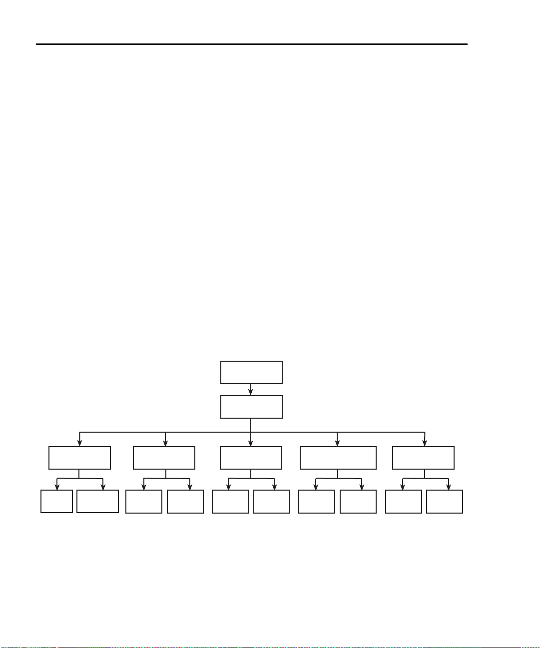
4-2 Ohms Measurements 2400 Series SourceMeter® User’s Manual
CONFIG
Ω
GUARD
SOURCE
SENSE
MODE
OFFSET
COMPENSATION
SRC
RDBK
MANUALAUTO 4-WIRE2-WIRE CABLEOHMS DISABLEENABLE DISABLEENABLE
Ohms configuration menu
NOTE For the Model 2430 Pulse Mode, offset-compensated ohms cannot be
enabled from the ohms configuration menu. However, offset-compen
sated ohms is available as a math function (Section 8, “Math opera-
tions”).
To access the ohms configuration menu, press CONFIG then OHMS. Use
Section 1, “Rules to navigate menus,” to select the various items in the menu tree,
which is shown in Figure 4-1. Menu items include:
• SOURCE — Select AUTO or MANUAL source mode.
• SENSE MODE — Select 2-WIRE or 4-WIRE sense mode.
• GUARD — Choose OHMS or CABLE guard.
• OFFSET COMPENSATION — Enable or disable offset-compensated
ohms (not valid for Model 2430 Pulse Mode).
• SRC RDBK — Enable or disable source readback mode.
The following paragraphs discuss each of these aspects in detail.
-
Figure 4-1
Ohms configuration menu tree
Page 82

2400 Series SourceMeter® User’s Manual Ohms Measurements 4-3
Ohms measurement methods
NOTE For the Model 2430, the following ohms measurement procedures
assume that the DC Mode of operation is selected (“Vsrc” or “Isrc” dis
played in the source field). If in the Pulse Mode (“Vpls” or “Ipls” displayed), you can select the DC Mode by pressing CONFIG V or I,
selecting the SHAPE menu item, and then selecting DC. Pulse Mode
operation is covered in
There are two methods to measure ohms: auto ohms and manual ohms. When
using auto ohms, the SourceMeter operates as a conventional constant-current
source ohmmeter or DMM. To use this method, simply select an ohms measurement range (or use autorange), and take the reading from the display. When
using auto ohms, the default test current varies with the ohms range, as summarized in Table 4-1.
NOTE You cannot change the test current in the auto ohms mode. If you
attempt to change the source current in auto ohms, the SourceMeter will
display an error message.
With the manual ohms mode, you can select either source V or source I to make
ohms measurements, and the unit will automatically compute the resistance reading using the V/I measurement method. After configuring the desired source and
selecting a voltage or current measuring range, select the Ω measurement
method to display the calculated V/I ohms reading.
Section 5.
-
NOTE To achieve optimum accuracy, the SourceMeter measures both V and I
and uses these values in ohms calculations (with source readback
enabled). The measured source value is more accurate than the pro
grammed source value. For remote operation, the user specifies the
functions to measure. See the resistance measurement accuracy specifi
cations in Appendix A.
-
-
Page 83

4-4 Ohms Measurements 2400 Series SourceMeter® User’s Manual
Table 4-1
Auto ohms default test currents
2400, 2400-LV, 2401,
Auto ohms
range
2Ω
20Ω
200Ω
2kΩ
20kΩ
200kΩ
2MΩ
20MΩ
200MΩ
and 2410
default test current
-
100mA
10mA
1mA
100µA
10µA
1µA
1µA
100nA
Selecting ohms measurement method
On power-up, auto ohms is the default method for the ohms function. Perform the
following steps to check and/or change the ohms measurement method:
1. Press CONFIG and then Ω to display the ohms configuration menu.
2. Using the EDIT keys, place the cursor (flashing menu item) on SOURCE
and press ENTER.
NOTE Cursor position indicates the presently selected ohms measurement
method. To retain this selection, use the EXIT key to back out of the
menu structure and skip the next two steps.
2420, 2425, 2430, and
2440
default test current
1A
100mA
10mA
1mA
100µA
10µA
10µA
1µA
-
3. To change the measurement method, place the cursor on the alternate
selection (AUTO or MANUAL), and press ENTER.
4. Press EXIT to exit from the menu structure.
Ohms measurement procedure
Perform the following steps to perform auto ohms measurements.
NOTE The following procedure assumes that the SourceMeter is already con-
nected to the DUT as explained in Section 2, “Connections.”
Page 84

2400 Series SourceMeter® User’s Manual Ohms Measurements 4-5
WARNING To prevent electric shock, do not make or break connections to
the SourceMeter with the output on. If on, press the ON/OFF
OUTPUT key to turn the output off.
1. Select ohms measurement function by pressing MEAS Ω.
2. Select the ohms measurement method (AUTO or MANUAL).
NOTE Use the manual ohms mode and the V-source method when high-speed
settling is required.
3. For manual ohms, configure source.
For manual ohms, you can Source I or Source V at the user-programmed
output level. The lowest allowable compliance limit is based on the load
and the source value. For example, if sourcing 1V to a 1kΩ resistor, the
lowest allowable current compliance is 1mA (1V/1kΩ = 1mA). Setting a limit
lower than 1mA will place the source in compliance.
4. Select measurement range.
Use the RANGE keys to select a range appropriate for the expected ohms
reading, or use autorange by pressing AUTO. When using manual ranging,
selecting the most sensitive (lowest) range provides the best accuracy.
Autorange automatically goes to the most sensitive range.
5. Turn output on.
Turn the output on by pressing the ON/OFF OUTPUT key. The OUTPUT
indicator will turn on to indicate the output is on.
6. Observe reading on display.
The SourceMeter will go into compliance if you exceed the maximum ohms
measurement range.
7. Turn output off.
When finished, turn the output off by pressing the ON/OFF OUTPUT key.
The OUTPUT indicator light will turn off.
Page 85

4-6 Ohms Measurements 2400 Series SourceMeter® User’s Manual
SourceMeter
HI
LO
I
V
M
Input, Output
V
M
V
R
Test Current (I)
Resistance
Under Test
Lead
Resistances
R
S
R
LEAD
R
LEAD
= Current sourced by SourceMeter
= Voltage measured by SourceMeter
= Voltage across resistor
I
V
M
V
R
Measured resistance = = + (2 × )
Actual resistance = =
V
M
I
R
S
R
LEAD
I
V
R
R
S
Ohms sensing
Ohms measurements can be made using either 2-wire or 4-wire sensing. (See
Section 2 for information on connections and sensing methods.) Note that resis-
tance measurement accuracy specifications are based on using 4-wire sensing.
The 2-wire sensing method has the advantage of requiring only two test leads.
However, as shown in Figure 4-2, test lead resistance can seriously affect the
accuracy of 2-wire resistance measurements, particularly with lower resistance
values. The 4-wire sensing method shown in Figure 4-3 minimizes or eliminates
the effects of lead resistance by measuring the voltage across the resistor under
test with a second set of test leads. Because of the high input impedance of the
SourceMeter voltmeter, the current through the sense leads is negligible, and the
measured voltage is essentially the same as the voltage across the resistor under
test.
Figure 4-2
2-wire resistance sensing
Page 86
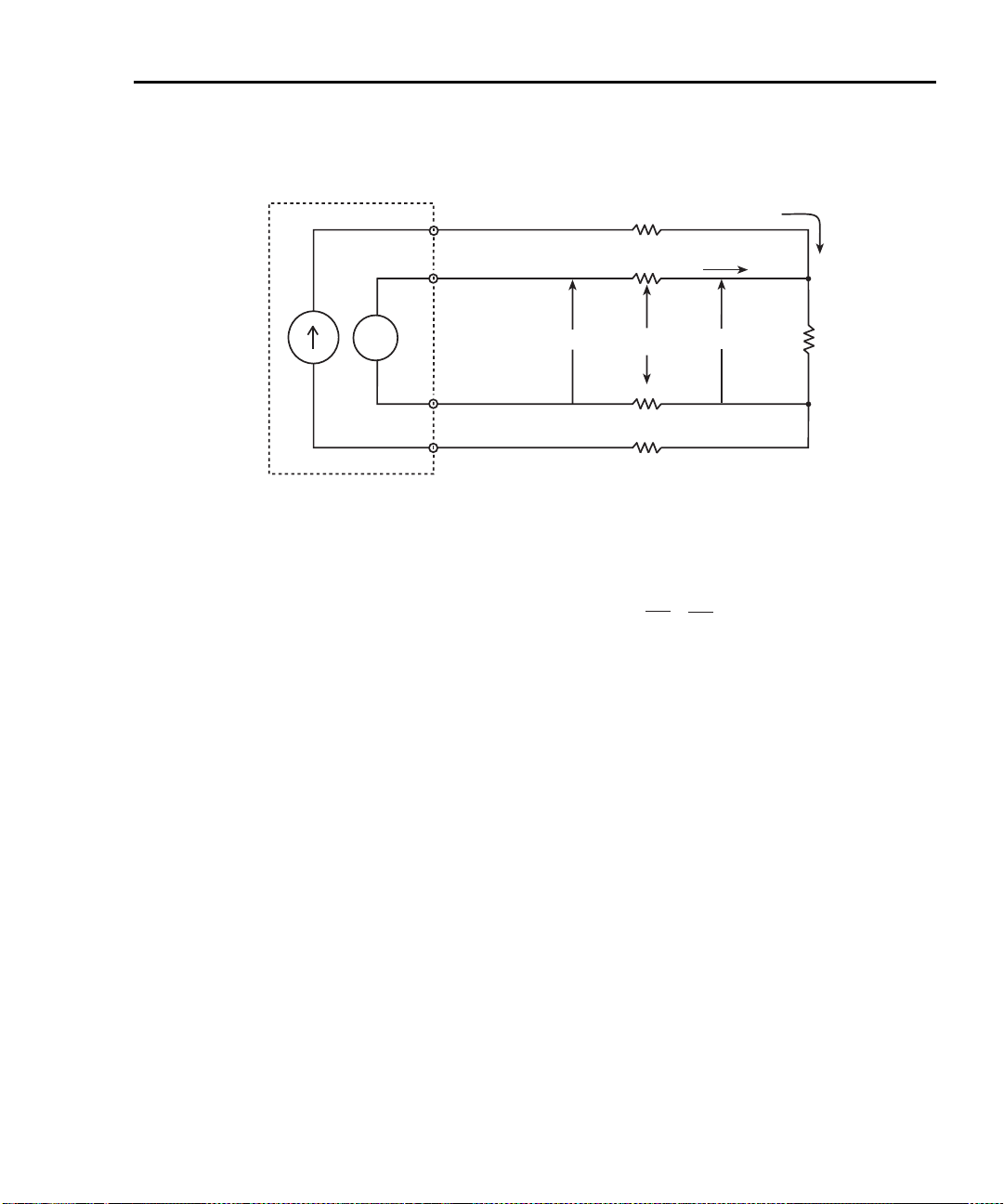
2400 Series SourceMeter® User’s Manual Ohms Measurements 4-7
SourceMeter
4-wire Sense HI
4-wire Sense LO
I
Input/Output HI
V
M
V
R
Test Current (I)
Resistance
Under Test
Lead
Resistances
R
S
R
LEAD
R
LEAD
= Current sourced by SourceMeter
= Voltage measured by SourceMeter
= Voltage across resistor
I
V
M
V
R
and measured resistance = =
V
M
I
V
M
Sense Current (pA)
Input/Output LO
R
LEAD
R
LEAD
Because sense current is negligible, =
V
M
V
R
I
V
R
Figure 4-3
4-wire resistance sensing
Sense selection
To select sensing mode, press CONFIG then Ω, select SENSE MODE, then
choose 2-wire or 4-wire.
Page 87

4-8 Ohms Measurements 2400 Series SourceMeter® User’s Manual
Offset-compensated ohms
NOTE For the Model 2430, the following offset-compensated ohms method is
not valid in the Pulse Mode. However, offset compensated ohms is avail
able as a math function (Section 8, “Math operations”).
-
The presence of thermal EMFs (V
surement accuracy. To overcome these unwanted offset voltages, use the offsetcompensated ohms measurement method.
In general, this method measures resistance (V/I) at a specific source level and
then subtracts a resistance measurement made with the source set to zero. With
the source set to zero, the source level is V
by the presence of V
This two-point measurement method is mathematically expressed as:
Offset-Compensated Ω = ∆V / ∆I where ∆V = V2 – V1 and ∆I = I2 – I1.
V1 is the voltage measurement with the source set to a specific level.
V2 is the voltage measurement with the source set to zero.
I1 is the current measurement with the source set to a specific level.
I2 is the current measurement with the source set to zero.
For auto ohms, the SourceMeter will select the appropriate current source level
and voltage measurement range. For manual ohms, first select the appropriate
source (V or I) value while the output is off. When the source is turned on, the
output will cycle between the programmed value and zero (0A or 0V) to derive the
offset-compensated ohms measurement.
is eliminated.
EMF
) can adversely affect low-resistance mea-
EMF
. Thus, the resistance contributed
EMF
Enabling/disabling offset-compensated ohms
Offset-compensated ohms is enabled or disabled from the OFFSET COMPENSATION option of the CONFIG OHMS menu.
Page 88

2400 Series SourceMeter® User’s Manual Ohms Measurements 4-9
Ohms accuracy calculations
Example accuracy calculations for various combinations of source readback, offset compensation, and normal/enhanced mode are shown below. See
Appendix A for detailed specifications.
Ohms accuracy of 100mΩ @ 5mA source current, normal mode
Source readback OFF, Offset Compensation OFF
Ohms accuracy = Isource accuracy + Vmeas accuracy:
I source accuracy = (5mA) (0.045%) + 2µA
2.25µA + 2µA = 4.25µA
4.25µA / 5mA = 0.085%
Vmeasure accuracy for (100mΩ) (5mA) = 500µV:
(500µV)(0.012%) + 300µV
60nV + 300µV = 300.06µV
300.06µV / 500µV = 60.01%
Total Ohms Uncertainty
60.01% + 0.085% = 60.09%
100mΩ
± 60.09% = 39.9mΩ to 160.09mΩ
Ohms accuracy of 100mΩ @5mA source current, normal mode
Source Readback ON
Ohms accuracy = Imeas accuracy + Vmeas accuracy:
Imeasure accuracy = (5mA) (0.035%) + 600nA
1.75µA + 600nA = 2.35µA
2.35µA / 5mA = 0.047%
Vmeasure accuracy = (500µV)(0.012%) + 300µV
60nV + 300µV = 300.06µV
300.06µV / 500µV = 60.01%
Total Ohms uncertainty:
60% + 0.047% = 60.06%
100mΩ
± 60.06% = 39.94mΩ to 160.06mΩ
Page 89

4-10 Ohms Measurements 2400 Series SourceMeter® User’s Manual
Ohms accuracy of 100mΩ @ 5mA source current, enhanced mode
Source Readback ON, Offset Compensation ON
Ohms accuracy = [Imeas % Rdg accuracy + Vmeas % Rdg accuracy] + System
noise*
Imeasure accuracy = (5mA)(0.035%)
1.75µA
Measured system noise: 00.0000mA
1.75µA+ 00.0000mA = 1.75µA
1.75µA / 5mA = 0.035%
Vmeasure gain accuracy for (100mΩ) (5mA) = 500µV
(500µV) (0.012%) =60nV
Measured system noise: 000.002mV
60nV + 2µV = 2.06µV
2.06µV / 500µV = 0.412%
.035% + 0.412% = 0.447%
100mΩ +/- 0.447%
99.55mΩ to 100.44mΩ
*System noise includes the external connection to DUT. To determine system
noise, the voltage and current noise is measured with test leads connected to the
DUT.
For example, with the 100mΩ resistor connected, the noise voltage was mea-
sured by pressing V measure, selecting the appropriate 200mV range, pressing
the REL button and making note of the systems noise magnitude. In this example,
the measurement was 000.002mV or 2µV.
To measure the current source noise, change the measure function to current
measure, select the appropriate current range (in this case, 10mA), press REL
and note the system noise magnitude. In the example, the system noise current
component was measured as 00.0000mA.
Page 90

2400 Series SourceMeter® User’s Manual Ohms Measurements 4-11
Ohms source readback
NOTE For the Model 2430 Pulse Mode, ohms source readback cannot be
enabled.
With ohms source readback enabled, the instrument measures the actual source
value instead of the programmed value used for ohms measurements and then
uses that measured value for reading calculations. Normally, ohms source readback should be left enabled for optimum ohms measurement accuracy because
SourceMeter measurement accuracy is better than source programming accuracy. (See specifications in Appendix A.) However, disabling source readback will
allow you to make valid ohms measurements with the source in compliance. See
Section 6, “Source I measure I and source V measure V,” for more details.
Ohms source readback selection
Use the following procedure to enable or disable ohms source readback:
1. Press CONFIG then Ω.
2. Select SRC RDBK, then press ENTER.
3. Select DISABLE or ENABLE as desired, then press ENTER.
4. Press EXIT to return to normal display.
NOTE Readings in the compliance field will be invalid with source readback dis-
abled.
Page 91

4-12 Ohms Measurements 2400 Series SourceMeter® User’s Manual
6-wire ohms measurements
The 6-wire ohms measurement configuration allows you to make accurate resistance measurements on resistor networks and hybrid devices in cases where
internal resistance connection nodes are not accessible. The combination of 4wire Kelvin connections and guarded ohms features eliminates the effects of internal parallel resistances that could degrade measurement accuracy and reduce
measurement speed. The basic procedure for setting up the SourceMeter for 6wire ohms measurements is covered below.
NOTE See Figure 2-5C for 6-wire ohms connections. See also Section 2,
“Ohms guard,” and Section 6, “Guard.”
1. Press CONFIG then Ω to display the CONFIG OHMS menu.
2. Select SENSE MODE, then press ENTER.
3. Select 4-WIRE, then press ENTER.
4. From the CONFIG OHMS menu, select GUARD, then press ENTER.
5. Select OHMS, then press ENTER.
6. Press EXIT to return to normal display.
7. Press MEAS then Ω to select the ohms measurement function.
8. Select the appropriate measurement range, or use autoranging if desired.
9. Turn on the output by pressing the ON/OFF OUTPUT key.
10. Take readings from the display.
11. Turn the output off when done by pressing the ON/OFF OUTPUT key.
Page 92

2400 Series SourceMeter® User’s Manual Ohms Measurements 4-13
Remote ohms programming
The following paragraphs summarize those basic commands necessary for
remote ohms programming and also give a programming example for a typical
ohms measurement situation.
Remote ohms commands
Table 4-2 summarizes the remote commands for making basic ohms measure-
ments. See Section 18 for more details on these commands.
Table 4-2
Remote commands for basic ohms measurements
Command Description
:SENSe:FUNCtion “RESistance”
:SENSe:RESistance:RANGe <n>
:SENSe:RESistance:MODE <name>
:SENSe:RESistance:OCOMpensated <state>
:SENSe:VOLTage:PROTection <n>
:SENSe:CURRent:PROTection <n>
:SOURce:FUNCtion <name>
:SYSTem:RSENse <state>
:OUTPut <state>
:READ?
Select ohms function.
Select ohms range (n = range).
Select ohms mode (name = MANual or AUTO).
Enable/disable offset compensation (state = ON or OFF).
Set voltage compliance n for manual ohms.
Set current compliance n for manual ohms.
Select source function (name = VOLTage or CURRent).
2-wire/4-wire sensing (state = ON, 4-wire; OFF, 2-wire).
Turn output on or off (state = ON or OFF).
Trigger and acquire reading.
Page 93

4-14 Ohms Measurements 2400 Series SourceMeter® User’s Manual
Ohms programming example
Table 4-3 summarizes the command sequence for a typical auto ohms measure-
ment. These commands set up the SourceMeter as follows:
• Ohms mode and range: auto, 20kΩ
• Offset compensation: off
• Sense mode: 4-wire
Table 4-3
Auto ohms programming example
Step Action Command Description
*RST
1
Select function
2
Select ohms mode
3
Select range
4
Output on
5
Get reading
6
Output off
* Numbers correspond to steps in “Ohms measurement procedure,” procedure, page 4-4.
FUNC “RES”
RES:MODE AUTO
RES:RANG 20E3
:SYST:RSEN ON
:FORM:ELEM RES
:OUTP ON
:READ?
:OUTP OFF
Restore GPIB defaults.
Select ohms measurement function.
Auto ohms mode.
Select 20kΩ range.
Enable 4-wire sensing.
Resistance reading.
Turn on output.
Trigger and acquire reading.
Turn off output.
Page 94

5
Pulse Mode Operation (Model 2430 only)
• Overview — Provides a summary of Pulse Mode operation.
• Pulse characteristics — Describes the timing characteristics that make up
the pulse width and output off-time of the pulse period. Explains how to
achieve the fastest pulse output.
• Pulse energy limitations (10A range) — Covers pulse energy consumption limitations for the 10A (source or measure) range.
• Pulse Mode configuration — Explains how to select and configure the
fundamental aspects of Pulse Mode operation.
• Pulse-measure considerations — Explains the operational differences
between normal (DC Mode) and Pulse Mode operation.
Page 95

5-2 Pulse Mode Operation (Model 2430 only) 2400 Series SourceMeter® User’s Manual
Pulse Period
0V or 0A
Output Off-Time
Pulse Width
(Output On-Time)
Overview
NOTE The Pulse Mode is only available for the Model 2430. The documentation
in this section does not apply to the Models 2400, 2400-LV, 2401, 2410,
2420, 2425, and 2440.
While in the Pulse Mode, the Model 2430 can output one or more pulses. A pulse
is formed by turning the output on for a period of time, and then turning the output
off (0V or 0A). A single pulse period is shown in Figure 5-1.
The Model 2430 can output current pulses up to 10.5A at 105V or voltage pulses
up to 105V at 10.5A. Pulse output polarity can be positive or negative. While in the
fixed source mode, the output will alternate between the set pulse level and zero
(0V or 0A). When performing a sweep, the output will alternate between each
sweep step/point and zero. See Section 10 for details on sweep operation.
A pulse reading is only performed while the output is on. When the output is off
(0V or 0A), a reading is not performed. For remote operation, the pulse reading
can be disabled.
Auto and manual ohms measurements can be performed while in the Pulse
Mode. Also, offset-compensated ohms is available as a math function (FCTN).
However, ohms source readback cannot be enabled in Pulse Mode.
Figure 5-1
Pulse period
Page 96
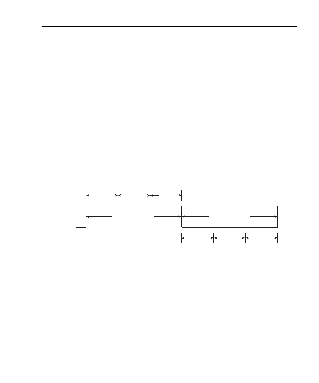
2400 Series SourceMeter® User’s Manual Pulse Mode Operation (Model 2430 only) 5-3
80µs
Meas
Sig
2.9ms
Meas
Ref &
Zero
PD
Delay = Pulse width delay, used to achieve pulse width setting.
80µs = Minimum pulse width overhead
Meas Sig = Signal measurement
2.9ms = Minimum output off-time overhead
Meas Ref & Zero = Reference and zero measurement
PD = Pulse delay setting, used to determine time between pulses.
0V or 0A
Delay
Pulse Width
(Output On-Time)
Output Off-Time
Pulse characteristics
NOTE For the purpose of discussion, positive polarity pulses are shown in the
following illustrations. Keep in mind that the Model 2430 can output neg
ative pulses.
As shown in Figure 5-1, a pulse period consists of an output on-time (pulse width)
and an output off-time. Depending on how the SourceMeter is configured, the
pulse width can be as short as 150µsec or as long as 5msec. With measurement
enabled, the output off-time can be as short as 2.9msec or as long as
~10,000sec. The shortest output off time is 1.1msec with measurements disabled.
See Table 5-1, “SourceMeter pulse mode timing summary” for details.
Figure 5-2 shows the components that make up the pulse width and the output
off-time.
NOTE See the Model 2430 specifications in Appendix A.
Figure 5-2
Pulse-measure timing for default source-measure configuration.
-
Page 97

5-4 Pulse Mode Operation (Model 2430 only) 2400 Series SourceMeter® User’s Manual
Table 5-1
SourceMeter pulse mode timing summary
Maxi-
Setting
1,2
Minimum
Pulse Width
(msec)
mum
Pulse
Width
(msec)
Minimum
Output
Off Time
(msec)
W/ Dis-
play Dis-
abled
(msec)
Default source-measure cycle
with auto zero on, current
0.15 5.0 5.0 4.0
range <10A.
Source-Measure cycle with
auto zero off, current range
0.15 5.0 2.9 1.9
<10A.
Source only, current range
<10A.
Source-Measure cycle with
autozero on, current range set
to 10A.
Source-Measure cycle with
autozero off, current range set
to 10A.
Source only, current range
set to 10A.
1
Pulse delay is set to zero for all settings.
2
For consistent pulse period, duty cycle should not exceed 8%
Note: Minimum output off time assumes minimum pulse width setting.
Pulse width
The pulse width can be set from 0.15msec to 5.00msec. However, depending on
how the SourceMeter is configured, the pulse width setting may not be achievable. For example, if it takes 1.667msec to perform the signal measurement, the
minimum pulse width that can be achieved is 1.75msec (1.667msec signal measurement plus 80µsec overhead). Therefore, if the pulse width setting is shorter
than what is achievable, the setting is ignored.
0.15 5.0 2.9 1.9
0.15 2.5 5.0 4.0
0.15 2.5 2.90 1.9
0.15 2.5 2.90 1.9
Page 98

2400 Series SourceMeter® User’s Manual Pulse Mode Operation (Model 2430 only) 5-5
The maximum pulse width for the 10A range (source or measure) is 2.5msec. If
the setting is >2.5msec, the SourceMeter will limit the pulse width to 2.5msec.
Signal measurement
A pulse reading consists of three measurement conversions. The signal (pulse) is
measured, a precise internal reference is measured, and finally, zero (common) is
measured. The reading is calculated from these measurements.
As shown in Figure 5-2, the signal measurement (Meas Sig) is a component of the
pulse width, while the reference and zero measurements (Meas Ref & Zero) are
components of the off-time. The measurement process is split up this way to allow
the shortest possible pulse width. The time to perform the signal measurement
depends on the speed setting (NPLC) of the SourceMeter and the power line frequency:
Meas Sig = NPLC / Line Frequency
Where: Meas Sig is the time it takes to measure the signal.
NPLC is the present speed setting (0.004 to 0.100 PLC).
Line Frequency is the frequency of the power line (50 or 60 Hz).
NOTE For front panel operation, the menu to set speed is displayed by pressing
the SPEED key. For remote operation, speed is set using an :NPLCycles
command. See
Section 7, “Speed,” for details.
Overhead time
As shown in Figure 5-2, there is some pulse width overhead time that is inherent
to the measurement process. The 80µsec is the minimum overhead times that
can be achieved. If the SourceMeter is configured to perform additional operations (e.g., math calculations, relative, store, sweep), this time will be higher.
Pulse width delay
When the pulse width setting is greater than the sum of the signal measurement
and overhead times, a delay is used to achieve the desired pulse width. This
delay is automatically calculated by the instrument using the following equation:
Pulse Width Delay = PW - Sig Meas - 80µsec
Where: PW is the pulse width setting
Sig Meas is the signal measurement time
80µsec is the minimum pulse width overhead time
For example, assume the pulse width setting is 1msec, and the signal measurement time is 167µsec. For the 80µsec overhead time, the pulse width delay is
753µsec:
Page 99

5-6 Pulse Mode Operation (Model 2430 only) 2400 Series SourceMeter® User’s Manual
Pulse Width Delay = 1msec - 167µsec - 80µsec = 753µsec
NOTE If the result of the pulse width delay calculation is a negative number,
pulse width delay is set to 0sec. A negative number indicates that the
pulse width setting is too short (not achievable).
Output off-time
Reference and zero measurements
As previously explained in “Pulse width,” “Signal measurement,” the reference
and zero measurements for a pulse reading are performed during the output offtime of the pulse period (Figure 5-2). The time to perform these two measurements depends on the speed setting (NPLC) of the SourceMeter and the power
line frequency:
Meas Ref & Zero = 2 x NPLC / Line Frequency
Where: Meas Ref & Zero is the time it takes to measure the reference and zero.
NPLC is the present speed setting (0.004 to 0.1 PLC).
Line Frequency is the frequency of the power line (50 or 60 Hz).
Overhead time
As shown in Figure 5-2, there is some overhead time that is inherent to the
source-measure process. The 2.9msec is the minimum overhead time for a
source-measure cycle that can be achieved during the output off-time. The minimum output off-time may vary depending on instrument settings (see Table 5-1 on
page 5-4 for details). If the SourceMeter is configured to perform additional opera-
tions (e.g., math calculations, relative, store, sweep), this time will be higher.
Pulse delay
The pulse delay (PD) is set by the user. It can be set from 0 to 9999.999sec. The
total output off time is the addition of the pulse delay, auto zero measurement
time, and the minimum output off time of the instrument.
Pulse duty cycle
Duty Cycle is the percentage of time during the pulse period that the output is on.
It is calculated as follows:
Duty Cycle = Pulse Width / (Pulse Width + Off-time)
For example, if the pulse width is 1msec and the off-time is 9msec, the duty cycle
is calculated as follows:
Page 100

2400 Series SourceMeter® User’s Manual Pulse Mode Operation (Model 2430 only) 5-7
80µs
Meas
Sig
PD
Delay = Pulse width delay, used to achieve pulse width setting.
80µs = Minimum pulse width overhead
Meas Sig = Signal measurement
1.4ms = Minimum output off-time overhead
PD = Pulse delay setting, used to determine time between pulses.
2.9ms
0V or 0A
Delay
Pulse Width
(Output On-Time)
Output Off-Time
Duty Cycle= 1msec / (1msec + 9msec)
= 1msec / 10msec
= 0.10
= 10%
Based on the possible output on/off times that can be configured, the pulse duty
cycle can range from <1% to 83.5%.
NOTE Pulse Duty Cycle on the 10A range should be limited to 8% for consistent
pulses. Please see
“Pulse energy limitations (10A range),” page 5-9.
Fast pulse output
The fastest pulses are achieved by configuring the SourceMeter for the shortest
pulse width and shortest output off-time. This is accomplished by setting the measurement speed to 0.004 PLC, setting the pulse delay to 0sec, disabling auto
zero, and making sure that no other operations (i.e., relative, math calculations,
store, sweep) are being performed. Please see Table 5-1 for details.
Auto zero
The output off-time can be reduced by disabling auto zero. With auto zero disabled, only the signal is measured. As shown in Figure 5-3, the reference and
zero measurements (which normally are part of the off-time) are not performed.
Also note that the minimum overhead time that occurs during the off-time is
reduced to 2.9msec. Therefore, with pulse delay set to 0sec, the output off-time
can be as short as 2.9msec.
Figure 5-3
Pulse-measure timing (auto zero off)
 Loading...