

Page 1
Instruction Manual
Model 193
System DMM
01985, Keithley Instruments, Inc.
Instrument Division
Cleveland, Ohio, U.S.A.
Document Number 193-901-01
Page 2

Page 3

SAFETY PRECAUTIONS
The following safety precautions should be observed before operating the Model ‘I93
This instrument is intended for use by qualified personnel who recognize shock hazards ,Ind arc f~u~~ili.~t
with the safety precautions required to avoid possible injury. Read over the manual carefully bei~rc upcrating
this instrumen(.
Exercise extreme caution when a shock hazard is present at the instrument’s input. The American Nati,,nal
Standards Institute (ANSI) states that a shock hazards exists when voltage levels greater than XlV rms 01
42.4V peak are present. A good safety practice is to expect that a hazardous voltage is present in any unknown
circuit before measuring.
Inspect the test lends for possible wear, cracks or breaks before each use. If any defects are fl,und, wplxe
with test leads that have the same measure of safety as those supplied with the instrument.
For optimum safety do not touch the test leads or the instrument while power is applied to the circuit under
test. Turn the power off and discharge all capacitors, bcforc connecting or disconnecting the instrunwnt.
Always disconnect all unused test leads from the instrument.
Do not touch any object which could provide a current path to the common side of the circuit under test
or power line (earth) ground. Always make measurements with dry hands while standing on a dry, ill-
s&ted surface, capable of withstanding the voltage being measured.
Exercise extreme safety when testing high energy power circuits (AC line or mains, ctc). Refer tu the fligh
Energy Circuit Safety Precautions found in paragraph 2.6 (Basic Measurements).
Do not exceed the instrument’s maximum allowable input as defined in the specifications and operation
section.
Page 4

Page 5

SPECIFICATIONS
1 DC VOLTS
MAXIMUM
READING RESO: ~~~ -
RANGE (5% Digits)
2 V 2:lY999 V ‘I pv ‘IO ,v >~IGO 0.002 + 1 O.UO5 + 2
20 v 2~1.9999 v
200 V 219.999 V ~100 @V ~ImV IOMR
1000 v 1000.00 v ~IlTlV ~lOl”V ~IOMR 0.004+ I 0.007+ I
*When properly zerued. **Multiply digit error by IO for h’i%digit accur~y.
NMRR: Crcater than 60dB at 50 or 60Hz.
CMRR: Greater than 120dB at dc and 50 or 60Hr
(with IkO in either lead).
MAXIMUM ALLOWABLE INPUT: ~IOOOV peak.
L”‘rI”N
6% 5% RESISTANCE 23°*10C 23:’ * 5°C 23”*5’;C 0”-18°C & 28 ‘-50 ‘C TIME”’
~10 pv ~100 pv 1OMR 0.003 + 1 0.007-1- ~1 0.009 + 3 0.0007+~,1, I < Ims
INPUT 24 Hr., 90 Days,
ACCURACY (5% Digits)**
+ (%rdg + counts)
L
0.005+2
0.003+ I
0.007+ I
MAXIMUM MEASUREMENT RATES (into internal
memory, filter and multiplex off):
3% Digit 4% Digit
1000 rdg:s 333 “dg; s 25 rdg,*
AC VOLTS (Option 1930)
MAXIMUM
READING
(5% Digits)
2v 2.1Y999V ‘I ,rV
2uv 2~1.9Y99V 10 pv I 00 ,rV
2OOV 2’19.999V ~lnn pv ImV
701lV 700.00 v ‘IlllV
*Above 2000 counts. **
Abow 2OOOt1 counts; 3%+500 lypicd b&w 2OOl10. “*Multiply digit crrlw 13~ Ill fur O’~di~it .xcur.x\
RESOLUTION
6% 5’,>
IO pv ~1 + 100 0.21 + IUU
I ~+ 1nu 0.25+ IUU l1~3i+300
~I + Ino 11.25 + ~IOU ,I.35 + 301,
IOmV 1 + ‘100 0.35+ 100 o., +3un
1 Yr.,
11.008+2’ o.onu3 in I
0.007 + 2
0.009 + 3 t1.ot107 4~ 0. I < 1111’
1).1109+5 t1.0007 +03 c 1111’
***To O.Ol’%> ot step chdng~
ACCURACY (5’:~ Digits)‘*’
I (%rdg ~+ counts,
50Hz-IOkHz’
0.35 +.m, I . SUli
TEMPERATURE
COEFFICIENT ANALOG
i (%rdg + counts), TIC SETTLING
< ?,,I> 200mV 219.99YmV IO0 nV 1 uV >lGG 0.003 + 2
o.ono3i~I1. I < I”,5
5’h Digit
6’h Digit
2.5 rds 5
I +~ i,ll,
I + ml
I i .iou
RESPONSE: True root mean square, ac or ac + dc.
CREST FACTOR: Rated accuracy to 3. Specified fat
pulse widths >lOPs, peak voltage 51.36 x full scale.
AC+DC: Add 60 counts to specified accuracy.
MAXIMUM INPUT: ‘IOOOV peak ac+dc, 2x’107V*Hz.
SETTLING TIME: 0.5s to within (1.~1% uf change in
reading.
INPUT IMPEDANCE: 1MIl shunted by less than 120pF.
TEMPERATURE COEFFICIENT CO”-18°C & 28”-50°C):
ILess than +(O.lxapplicable accuracy spccification)i”C
below 50kHz; (0.2x) for 5OkHz to 100kHz. ‘Typical
ACCURACY (1 Year)
(3% Digits)
e P/ad8 + counts)
RESOLUTION
..-
18”-28°C
2+3
2+3
2+3
2+3
21~3
3dB BANDWIDTH: .i00kl I% typic,d
CMRR: C;realer than htldll at 50 ,~nd hOtI/ (Ikl! ,,w
b&IlC~).
dBV (Ref. = 1V): ACCURACY idRV
44 tii t.i7dBV
(20llmV ti, 7OtiV rms) 0.2 (I,4
-34 to 14dBV
(2OmV tc 21UlmV)
RESPONSE: True rout mean squaw, ac -+ dc.
BANDWIDTH: 0.1 to 1011~.
1 Year, 18 -28 c
INPUT ZOHz-20kHz ZOkHz-lOOklIz RESOLUTION
Il.llldB\’
I.5
7’
0 lll‘lil\’
Page 6

OHMS
MAXIMUM
READING
RANGE
200 0
2 kO
20 k0
200 kl2
2MQ
2OMSl
200Mn
*When properly zeroed. **Nominal short circuit current.
***4-terminal accuracy 200R-20k range. Multiply digit error by 10 for 6%d accuracy
(5% Digits)
219.999 12
2.1Y99Y kl2
21.9999 kn
219.999 kR
2.19999MII
21.9999Mn
219.999M12
RESOLUTION
6% 5%
100 $2 lm0
lmll ~IOmR
1Omfl 1OOmn
~loomn 1 0
1 n 10 n
10 n 100 n
100 R 1 kn
CURRENT
THROUGH
UNKNOWN
‘ImA
ImA
100 PA
10 PA
1 PA
100 nA
100 n/t**
ACCURACY (5’h Digits)***
+ (%rdg + counts)
24 Hr., 90 Days, 1 Yr.,
23°+10c
0.0035+2* 0.007+2* 0.010+2*
0.0035+2 0.007+2 0.0’10+2
0.0035 + 2 0.007+2 0.010+2
u.o035+2
0.005 +2 0.010+2 0.010+2
0.040 +2 0.070+2 0.070+2
3.2 +2 3.2 +2 3.2 +2
23’+ 5°C
0.007+2 0.010+2
23”tST
TEMPERATURE
COEFFICIENT
*(%rdg+counts)l”C
O”lE°C & 28’-50°C
0.00’1 +0.7
0.001+0.1
0.001+11:1
0.001+0:1
0.001+0.1
0.010+0:1
0.230 + 0. ~1
CONFIGURATION: Automatic 2- or 4-terminal.
MAXIMUM ALLOWABLE INPUT: 350V peak or
250V rms.
DC AMPS (Option 1931)
ACCURACY
(5% Digits) TEMPERATURE
RESO-
LUTION *(%rdg+counts) #adg+counts)i”C
RANGE (5% Digits) 18~28°C
200 @A 1nA 0.09+10 0.01+0.5
2mA 1OnA 0.09+10 0.01+0.5
20mA IOOnA
200mA
2 A 1OpA
IpA
(1 Year)
0.09+10
0.09+10 O.Ol+ 0.5
0.09+ 10 0.01+0.5
COEFFICIENT
O’Q”C & 28c50T
0.0110.5
TRMS AC AMPS (Options 1930 and 1931)
ACCURACY*
45Hz to 1OkHz
(5% Digits)
RESO-
LUTION +Phrdg+counts) +(%rdg+counts)i”C
RANGE (5% Digits) 18%28T 00-18”C & 280-5OT
200 pA
2mA 1OnA 0.6+300 0.04+10
2OmA lOOnA 0.6+300 0.04 + 10
200mA
2 A IOpA 0.6+300
i *Above 2000 camts.
1nA
W
(1 Year)
0.6+300
0.6+300 0.04+10
TEMPERATURE
COEFFICIENT
0.04+10
0.04+10
MAXIMUM OPEN CIRCUIT VOLTAGE: - 7V.
OVERLOAD PROTECTION: 2A fuse (25OV), externally
accessible.
MAXIMUM VOLTAGE BURDEN: (1.25V on 2OOfiV
through 20mA ranges; 0.28V on 200mA range; 1V on
2A range.
RESPONSE: True root mean square, ac or ac + dc.
CREST FACTOR: Rated accuracy to 3. Specified for
pulse width > 1 ms, peak current 5 1.36 x full scale.
MAXIMUM VOLTAGE BURDEN: 0.25V on ZOO&V
through 2OmA ranges; 0.28V on 200mA range; 1V on
2A range.
OVERLOAD PROTECTION: 2A fuse (25OV), externally
accessible.
SETTLING TIME: 0.5s to within 0.1% of change in
reading.
dB (Ref. = ImA):
ACCURACY +dB
INPUT
-34 to +66dB
20pA to 2A
-54 to -34dB
2&A to 20fiA
1 Year, 18°-280c
45Hz-10kHr
0.3
2
RESOLUTION
O.OldB
O.OldB
Page 7
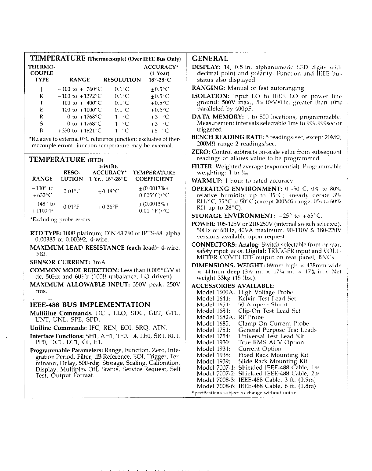
TEMPERATURE
THERMO-
COUPLE
TYPE RANGE
400 to + 760°C O.l”C
J
K
? -100 t” + 400°C
E
R
s 0 to + 1768°C
R +350 t” +1821”C 1 “C
*Relative to external 0°C reference junction; ~‘xcIusivc’ of ther-
mocouple errors. Junction temperature may be external.
ml to + 1372°C O.l”C +0.5”C
100 t” + 1ooov Kl”C
0 to +‘1768”C 1 “C +3 “C
TEMPERATURE
RESO-
RANGE LUTION 1 Yr., 18”-28°C COEFFICIENT
100” to
+630”C cl.llosT)/“c
-~ 148” to
+lloo”F 0.01 “F)PC
*Excluding probe errors.
RTD TYPE: 1000 platinum; DIN 43 760 or II’TS-68, alpha
0.00385 or 0.00392, 4.wire.
MAXIMUM LEAD RESISTANCE (each lead): 4-w&,
‘Ion.
SENSOR CURRENT: 1mA
COMMON MODE REJECTION: Less than 0.005”CIV at
dc, 50Hz and 60Hz (1000 unbalance, LO driven).
MAXIMUM ALLOWABLE INPUT: 350V peak, 250V
rms.
O.Ol”C *O.~l8”C
f..Ol”F
IThermocouple) (Over IEEE Bus Only)
ACCURACY’
(1 Year)
RESOLUTION 18”-28°C
*0.5”C
O.l”C YO.S”C
kO.hT
1 “C *3 “C
j5 “C
(RTD)
4-WIRE
ACCURACY* TEMPERATURE
*(fl.rm3%+
10.3h”F
~(0.0013%+
IEEE-488 BUS IMPLEMENTATION
Multiline Commands: DCL, LLO, SDC, GET, GTI.,
UNT, UNL, SPE, SPD.
Uniline Commands: IFC, REN, EOI, SRQ, ATN.
Interface Functions: SH1, AHl, TEO, L4, LEO, SRl, RLl,
PPO, DCl, DTl, CO, El.
kogrammable Parameters: Range, Function, Zero, Inte-
gration Period, Filter, dB Reference, EOI, Trigger, Tcrminator, Delay, 500.rd Storage, Scaling, Calibration,
Display, Multiplex Of, Status, Service Request, Self f
Test, Output Format.
GENERAL
DISPLAY: 14, 0.5.in. alphanumeric LED digits with
decimal point and polarity. Function and lf:EE bus
status also displayed.
RANGING: Manual or fast autoranging.
ISOLATION: Input LO to IEEE I.0 or power line
ground: 500V max., 5x l(l%‘*tlz; greater than IIPI!
paralleled by 400pF.
DATA MEMORY: ~1 to SO(l locations, pnrgr‘~r~~n~‘~hle.
Measurement intervals selcctablc ‘Ims to 999.999sec or
triggered.
BENCH READING RATE: 5 readings:wc, cuxpt 2Ohl!I;
200MR range 2 readingsisrc.
ZERO: Control subtracts w-scale valw from subseqwnt
readings or allows value to bc programmed.
FILTER: Weighted average (exponential). I’rogr.mm~~~hl~
weighting: 1 to li:.
WARMUP: ~1 hour to rated accur<rv.
OPERATING ENVIRONMENT: 0 -5iPC. (I%> to 80%
relative humidity up to 3PC; linearly dcr.lte 3%
RHPC. 35°C to 50°C (extent 2lIOM11 rr,nx: tl”,,, t,, 60%
RH up to 28°C). ’
STORAGE ENVIRONMENT: -25:’ to +hS’C.
POWER: ‘lO5-125V or ZlO-250V (internal switch selected),
50Hz or 60Hz, 40VA maximum 9(1-IlOV & 180.22OV
versions available upon request.
CONNECTORS: Analog: Switch s&ctabte front (>r rt’x,
safety input jacks. Digital: TRIGGEt< input and VOt.‘I~~
METER COMPLETE output on re.,r panel, HNCs.
DIMENSIONS, WEIGHT: 89mm high x 43Hmm wide
x 441mm deep (3’12 in. x 17’11 in, x l7:, in.). Net
weight 33kg (15 Ibs.).
ACCESSORIES AVAILABLE:
Model 160OA: High Voltage I’robc
Model 1641: Kelvin Test Lead Set
Model 1651:
Model 1681: Clip-On Test Lead Set
Model 1682A: RF Probe
Model 1685: Clamp-On Current Probe
Model 1751: Gener.71 I’urpw Test Leads
Model 1754: Universal Test Lead Kit
Model 1930: True RMS ACV Option
Model 1931: Current Option
Model 1938: Fixed Rack Mounting Kit
Model 1939: Slide Rack Mounting Kit
Model 7007-l: Shielded IEEE-488 Cable, lm
Model 7007-2: Shielded IEEE-488 Cable. 2m
Model 7008.3: IEEE-488 Cable, 3 ft. (0.9m)
Model 7008-6: IEEE-488 Cable, 6 ft. (l&m)
Specifications subject to change withut tnm~c,.
50.Ampere Shunt
,,
j
Page 8

Page 9
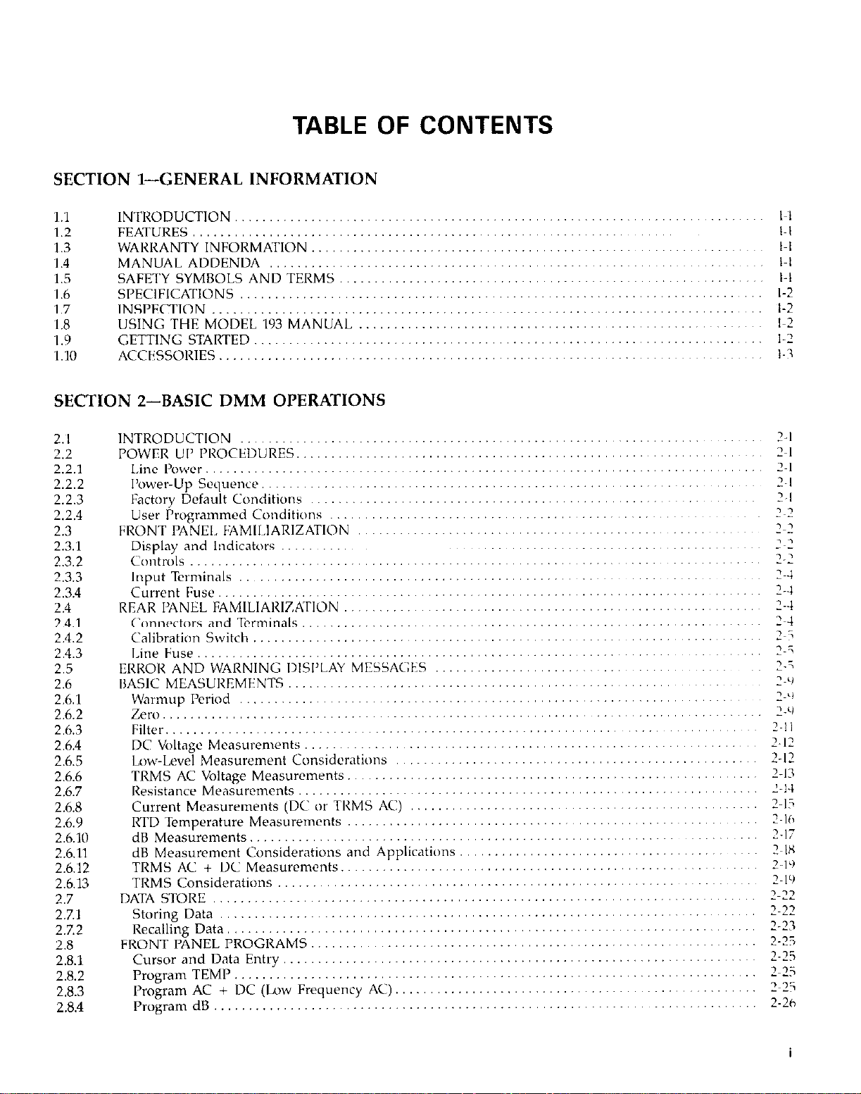
TABLE OF
CONTENTS
SECTION
1.1 INTRODUCTION
1.2
3.3
‘I .4
1.5 SAFETY SYMBOLS AND TERMS
‘I .6 SI’ECIFKATIONS
1.7
1.8
1.9
‘I.10
l-GENERAL INFORMATION
.........................
FEATURES.. .............................
WARRANTY INFORMATION ..............
MANUAL ADDENDA ....................
..........
.........................
INSPECTION .............................
USING THE MODEL ‘193 MANUAL ........
GETTING STARTED
ACCESSORIES ............................
.......................
SECTION 2-BASIC DMM OPERATIONS
2.1
2.2
2.2.1
2.2.2
2.2.3
2.2.4
2.3
2.3.1
2.3.2
2.3.3
2.3.4
2.4
2.4.1
2.4.2
2.4.3
2.5
2.6
2.6.1
2.6.2
2.6.3
2.6.4
2.6.5
2.6.6
2.6.7
2.6.8
2.6.9
2.6.10
2.6.11
2.6.12
2.6.13
2.7
2.7.1
2.7.2
2.8
28.1
2.8.2
2.8.3
2.8.4
INTRODUCTION ........................
POWER UI’ I’ROCEDIJRES
Line Power.
I’ower-Up Scquc”ce, ....................
Factory Default Conditions ..............
User Programmed Conditions ............
FRONT PANEL FAMII~.IARIZATION ........
Display and Indicators ...................
Co”tnlls
Input Terminals
C&rent Fuse
REAR PANEL FAMILIARIZATION
Connectors and Terminals ................
Calibration Switch ......................
Line Fuse..
ERR013 AND WARNING DISI’LAY MESSAGES
BASIC MEASUI~EMFN’I‘S.......................................................~~~~.~
Warmup Period ................................................................
...................................................................................
Zero
Filter...................................................~
DC V<,ltage Measurements
Lw+Level Measurement Considerations
TRMS AC Voltage
Resistance
Current Measurements (DC or TRMS AC)
RTD Temperature Measurements
dB Measurements
dB Measurement Considerations and Applications
TRMS AC + DC Measurcm~nts
TRMS Considerations
DATA STORE
Storing Data
Recalling Data ............................................................................
FRONT PANEL PROGRAMS ................................................................
Cursor and Data Entry
Program TEMP ...........................................................................
Program AC + DC (Low Frequency AC).
Program dB
............................
................................
........................
............................
.......
Measurements
Measurements
........................................................................
.........
.........
..,
...
................
..........
... ............
......... ..
....... ..
..................................................................
................................ ..................
..........................................................
................................................................
....................................................................
.............
..,
..............
....................................................................
... ... ...................................
... ...
... ... ...
........................ ........ ....
.................................
.............
................. ...............................
.........
......................................
..........................................
..................................................
..................................................
.............
... ., .........................
................................
.............................
.................. ...
..
........... .. .... ...
..
....................... ...........
.........
....
....
~,,~ ~.,,
.........
....
,,,
...
Page 10

2.8.5
2.8.6
2.8.7
2.88
2.8.9
28.10
2.8.11
2.8.12
2.8.13
2.8.14
2.8.15
2.9
2.10
2.lO10.1
2:11x2
2.10.3
Program ZERO..
Program FILTER
Program RESET
Program 4
Program 90 (Save)
Program 91 (IEEE Address)
Program 92 (Freq)
Program 93 (Diagnostics)
Program 94 (MX + B Status)
Program Y5 (Multiplexer)
Program 96 (CAL) ................................
FRONT PANEL TRIGGERING
EXTERNAL TRIGGERING
External Trigger
Voltmeter Complete
Triggering Example
.................................
..................................
..................................
.......................................
................................
........................
................................
..........................
......................
..........................
......................
..........................
..................................
..............................
..............................
SECTION 3-IEEE-488 PROGRAMMING
..........
..........
..........
..........
..........
..........
..........
..........
..........
..........
..........
..........
.........
.........
..........
..........
..........
..........
..........
..........
..........
..........
..........
..........
..........
..........
.........
.........
.........
.........
.........
.........
.........
.........
.........
2-26
2-26
2.27
2-27
2-28
2-28
2.29
2-29
2-29
2-30
2-30
2.30
2-30
2-30
2-31
2-w
3.7
3.2
3.3
3.3.1
3.3.2
3.3.3
3.4
3.4.1
3.4.2
3.4.3
3.4.4
3.4.5
3.5
3.6
3.6.1
3.6.2
3.6.3
3.7
3.7:1
3.7.2
3.7.3
3.R
38.1
3.8.2
3.8.3
3.8.4
3.9
3.9.1
3.Y.2
3.9.3
3.9.4
3.9.5
3.9.6
3.9.7
3.9.8
3.10
3.10.1
3.10.2
3.10.3
3.10.4
3.10.5
INTRODUCTION ..........................................................................
BUS DESCRIPTION ........................................................................
IEEE-488 BUS LINES .......................................................................
Data Lines..
Bus Management Lines ...................................................................
Handshake Lines
BUS COMMANDS .........................................................................
Uniline C~,mmands .......................................................................
Universal Commands ..: ..................................................................
Addressed Commands..
Unaddressed Commands ..................................................................
Device-Dependent Commands
COMMAND CODES..
COMMAND SEQUENCES.. ................................................................
Addressed Command Sequencr ............................................................
Universal Command Sequence
Device-Dependent Command Sequence
HARDWARE CONSIDERATIONS
Typical Controlled Systems
Bus Connections
Primary Address Programming. ...........................................................
SOFTWARE CONSIDERATIONS ............................................................
Controller Handler Software ..............................................................
Interface BASIC Programming Statements
Interface Function Codes .................................................................
IEEE Command Groups ..................................................................
GENERAL BUS COMMAND I’ROGIIAMMINC
REN (Remote Enable) ....................................................................
IFC(Interfacc Clear) ......................................................................
LLO (Local Lockout) .....................................................................
GTL (Go To Local) and Local .............................................................
DCL (Device Clear) ......................................................................
SDC (Send Device Clear) .................................................................
GET (Group Execute Trigger) .............................................................
Serial Polling (SI’E, SPD) .................................................................
DEVICE-DEPENDENT COMMAND PROGRAMMING, .......................................
Execute(X) ..............................................................................
Function(F) ..............................................................................
Range(R)
Zero (Z)
Filter(P)
.............................................................................
.........................................................................
..................................................................
.............................................................
.....................................................................
.............................................................
....................................................
............................................................
................................................................
.........................................................................
..................................................
..............................................
................................................................................
.................................................................................
.................................................................................
3-I
3-1
3-2
3-2
3-2
3-2
3-3
3-4
3-4
3-5
3-5
3-s
3-5
3-7
3-7
3-7
3-7
3-7
3-7
3-8
NO
s-10
i-10
3-K
s-11
1.12
3-12
3-13
3-13
3-14
3-14
3-14
3-15
3-15
3-16
3-17
3-20
3-20
3-21
3.22
3-22
ii
Page 11
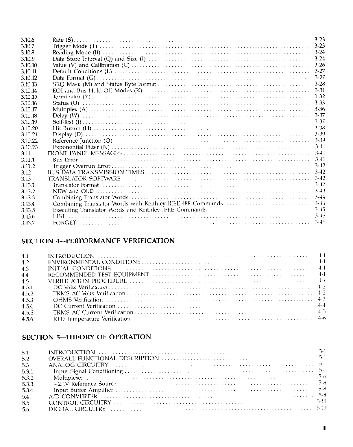
3.10.6
3.10.7
3.10.8
3.10.9
3.10.10
3.10.11
3.10.12
3.10.13
3.10.14
3.10.15
3.10.16
3.10.17
3.10.18
3.10.19
3.10.20
3.10.21
3.10.22
3.1023
3.11
3.11.1
3.11.2
3.12
3.13
3.13.1
3.U.2
3.13.3
3.13.4
3.13.5
3.13.6
3.13.7
Rate (S).
Trigger Mode (T)
Reading Mode (8) ........................................................................
Data Store Interval (Q) and Size (I)
Value (V) and Calibration (C)
Default Conditions (L) ....................................................................
Data Format (G)
SRQ Mask (M) and Status Byte Format.
EOIand Bus Hold-Off Modes ..........................................................
Terminator (Y) ............................................................................
status (LJ) ...............................................................................
Multiplex (A) ............................................................................
Delay (W) ................................................................................
Self-Test (J)
Hit Button (H) ...........................................................................
Display (D)
Reference Junction (0)
Exponential Filter (N)
FRONT PANEL M~SSAGTS...................................................~.~~ ..........
Bus Error
Trigger Overrun Error ..................................................................... 3-42
BUS DATA TRANSMISSION TIMES
TRANSLATOR SOFTWARE
Translator hlrmat
NEW and OLD
Combining Translator Words
Combining Translator Wurds with Kcithlcy ll%l~-488 Commands,
Executing Translator Words and Keithley IEEE Comnunds
LIST
F:ORGET ...............................................................................
.................................................................................
.........................................................................
........................................................ 3-24
.............................................................. 3-26
..........................................................................
.................................................... 3-2X
...............................................................................
.............................................................................. 3~39
....................................................................
......................................................... ..... .....
................................................................................
.........................................................
.................................................................
........................................................................
............................................................ ........
.................................... ...... .. ........
.......................... .. 3-14
......................
...........................................................................
~,
.,
....
.....
.......
3-23
3-23
3.24
3-27
3-27
3-31
3.32
3-33
3.36
3-37
3-37
3-3X
3-3’1
3-41
3-41
3.41
3-42
3-42
3-42
3-43
3-44
3-45
.%-.I?
iwli
SECTION 4--PERFORMANCE VERIFICATION
4.1
4.2
4.3
4.4
4~.5
4.5.~1
4.52
4.5.3
4.5.4
4.5.5
4.5.6
INTRODUCTION
ENVIRONMENTAL CONDITIONS
INITIAL CONDITIONS.......................................................~ ..............
RECOMMENDED TESf EQUIPMENT
VERIFICATION I~ROCEDURE
DC Volts Verification
TRMS AC Volts Verification.,
OHMS Verification
DC Current Verification
TRMS AC Current Verification
RTD Temperature Verification
... .... ...
... ...........
... ....
....................................................... ............ +I
........... . ...
......
................................................
...
........... .. ....... ..
...
...........
....................................... ...... .....
...
........ .. ..... .....
...
SECTION 5-THEORY OF OPERATION
5.1
5.2
5.3
53.1
53.2
5.3.3
5.3.4
5.4
5.5
5.6
INTRODUCTION
OVERALL FUNCTIONAL DESCRIPTION
ANALOG CIRCUITRY
Input Signal Conditioning
Multiplexer ..,
+2.1v Reference Source
Input Buffcr Amplifier
AID CONVERTER
CONTROI,ClRCUlTRY
DIGITAL CIRCUITRY ..,
........ . .......... . ..
.......................................................................
............................................................................ i-h
..
......................
....................................................................
..........................................................................
.....................................................................
.................................................................... 5~10
................
............. ..
................ ... ... ....
............. .. ..
.. ......
............
......................
............
.. ....
..........
...........
............
................ ......... .&(I
...............................
................................
,.,
...........
........ .....
......... &I
.. .. ... ..
.............. ......
............. ....
........ .............
......... ..... ..
......................
...........
4-I
&I
&I
-I-l
4.2
4~2
1~?
4-5
5-l
5-l
5-l
i-i
i-X
;~x
i-X
i-It1
...
111
Page 12

5.6.1
5.6.2
5.7
Microcomputer ...........................................................................
Display Circuitry ..........................................................................
POWER SUPPLIES
SECTION 6-MAINTENANCE
.........................................................................
5-10
S-10
5-K
6.1
6.2
6.3
6.3.1
6.3.2
6.4
6.5
6.6
b.b.‘l
6.6.2
6.6.3
6.6.4
6.6.5
6.6.6
6.6.7
6.6.8
b.b.9
h.b.10
6.6.11
6.6.12
6.7
6.8
6.9
6.9.1
6.9.2
b.Y.3
6.9.4
6.9.5
6.9.b
INTRODUCTION ...........................................................................
LINE VOLTAGE SELECTION
FUSE REPLACEMENT
Line Fuse
Current F~use
MODEL 1930 TRMS ACV OPTION INSTALLATION,,
MODEL 1931 CURRENT OPTION INSTALLATION
CALIBRATION ..............................................................................
Recommended Calibration Equipment
Environmental Conditions.,
Warm-Up Period ..........................................................................
Calibration Switch .........................................................................
Front Panel
IEEE-488 Bus Calibration
Calibration Sequence .......................................................................
DC Volts Calibration
Resistance Calibration
TRMS AC Volts Calibration
DC Current Calibration.
TRMS AC Current Calibration
DISASSEMBIdY INSTRUCTIONS
SPECIAL HANDLING OF STATIC-SENSITIVE DEVICES
TROUBLESHOOTING
Recommended Test Equipment
Power-Up Self Test .......................................................................
Program 93.Self Diagnostic Program.
Power Supplies ...........................................................................
Signal Conditioning Checks
Digital and Display Circuitry Checks
.................................................................................
..............................................................................
Callbratmn
.......................................................................
.......................................................................
................................................................. 6-l
..........................................
............................................ 6-3
....................................................... 6-3
................................................................ b-3
................................................................... b-b
....................................................................... 6-7
......................................................................
................................................................ h-10
................................................................... 6.13
............................................................. 6-14
.............................................................
...................................... b-21
...................................................................... 6-21
............................................................ 6.22
.......................................................
............................................................... 6-23
....................................................... 6-23
b-l
6-l
b-1
b-2
6-2
6-3
b-3
6-3
6-5
b-7
6-8
6.15
6.22
6-23
b-23
SECTION 7-REPLACEABLE PARTS
7.1
7.2
7.3
7.4
7.5 SCHEMATIC DIAGRAMS AND COMPONENT LOCATlON DRAWINGS
iv
INTRODUCTION.. .......................................................................... 7-l
I-ARTS LIST .................................................................................
ORDERING INFORMATION ................................................................. 7-l
FACTORY SERVICE .......................................................................... 7-l
7-l
......................... 7-l
Page 13

LIST OF ILLUSTRATIONS
2-l
2-2
2-3
2-4
2-5
2-6
2-7
2-8
2-9
2-10
2-u
3-l
3-2
3-3
3-4
3-5
3-6
3-7
3-8
3-9
3-10
3-11
3-12
3-13
4-1
4-2
4-3
4-4
4-5
4-6
4-7
Model 193 Front Panel
Model 193 Rear l’anel
DC Voltage Measurements ...................................................................
TRMS AC Voltage Measurements
Two’Terminal Resistance Measurements
Four-Terminal Resistance Mrasuremcnts
Current Measurements..
RTD Temperature Measurements
External Pulse Specifications
Meter Complete Pulse Specifications
External Triggering
IEEE-488 Bus Configuration
lEEE-488 Handshake Sequence
Command Groups
System Types..
Typical Bus Connector,,
IEEE-488 Connections..................................................................~~~~
Model 193 IEEE-488 Connector
Contact Assignments.,
General Data Format
SRQ Mask and Status Byte Fomr,lt
UO Status Word and Default V.llues
Ul Error Status Word..
tHit Button Command Numbers
Connections for DC Vc,lts Verification
Connections for TRMS AC Volts Verification
Connections for Ohms Verification (200%20kR) Range
Connections for Ohms Verifications (2OOk%200Mn Ranga)
Connections for DC Current Verification.
Connections for TRMS AC Current Verification
Connections for RTD Temperature Verification.
.......................................................................
........................................................................
............................................................
.......................................................
......................................... .............
....................................................................
.......................................... ... ..
....................................................... ...
.................................... ....
Example
..........................................................................
........................................................
....................................... ......... .....
.....................................................
...............................................................
.....................................................................
..................................................
............................................ ..........
.................................................. .....
.................................................................
....
............................................. ............
................................................... ......
............................................................ 3-3’1
....................
..............
.....
.................
...........
...........
,,....
?i
2?
2-12
2-l-1
Z-15
2~15
Z-lh
......
........ ...
.... .. 1-2
...
................... 3-X
.....
~,
....... ..
...
;:;;
l~.?l
2~32
3~3
3-1,
3-P
3.‘)
..
3~‘)
..
?-Ill
.%?‘I
3~2’)
3~34
1-3;
5-l
5-2
5-3
5-4
5-5
5-6
5-7
6-l
6-2
6-3
6-4
6-5
h-6
6-7
6-8
6-9
6-10
6-11
6-12
Overall Block Diagram ..............................................
Input Configuration During 2 and 4Tcmminal Resistance Measurements
Ohms Source (2kn Range Shown)
Resistance Measuwment Simplified Circuitry
JFET Multiplexer
Multiplexer Phases
A/D Converter Simplified Schematic
Models 1930 and 1931 Installation
DC Volts Calibration Configuration (2OOmV and 2V Ranges)
DC Volts Calibration Configuration (2OV-IOOOV Ranges).
Four-Wire Resistance Configuration (200%20kll Ranges)
Two-Wire Resistance Calibration Configuration (200kR.2OOMR Ranges)
Flowchart of AC Volts Calibration Procedure
TRMS AC Volts Calibration Adjustments,
TRMS AC Volts Calibration Configuration,
DC Current Calibration Configuration
TRMS AC Current Calibration Configuration
Co”“ectors
Model 193 Exploded View
...................................................
................................................
.........
...........................................................................................................................................
.................................
.........................
.................................
.............................................................
.....................................
............................ ............
.........................................
..................................................
.....................................................
....................................................
................................................ .......
..................................................
............................
(,-.l
;I::
&‘I
h-‘1
h-II
&i;
h-l-l
h-15
66;
Page 14
7-l
7-2 Display Board, Component Location Drawing, Dwg. No 193.130
7-3
7-4
7%
7-6
7-7
7-8
79
7-10
7-11
Jumper Board, Component Location Drawing, Dwg. No. 193-160
Display Board, Schematic Diagram, Dwg. No. 193.116
Digital Board, Component Location Drawing, Dwg. No. 193.100
Digital Board, Schematic Diagram, Dwg. No. 193.106
Analog Board, Component Location Drawing, Dwg. No. 193.120
Analog Board, Schematic Diagram, Dwg. No. 193.126
Model 1930, Component Location Drawing, Dwg. No. 1930-100
Model 1930, Schematic Diagram, Dwg. No. 1930.106
Model 1931, Component Location Drawing, Dwg. No. 1931-100
Model 1931, Schematic Location Drawing, Dwg. No. 1931-106
...........................................
...........................................
..........................................
...........................................
................................... 7-37
.................................
................................. 7-4
.................................
................................
................................. 7-35
.................................
7-3
7-5
7.10
7-n
7.22
7-23
7-38
7-39
vi
Page 15
LIST OF TABLES
2-l
2-2
2-3
2-4
2-5
2-6
2-7
2-8
3-l
3-2
3-3
3-4
3-5
3-6
3-7
3-8
3-9
3-10
3.11
3-12
3-13
3-14
3-15
3-16
3-17
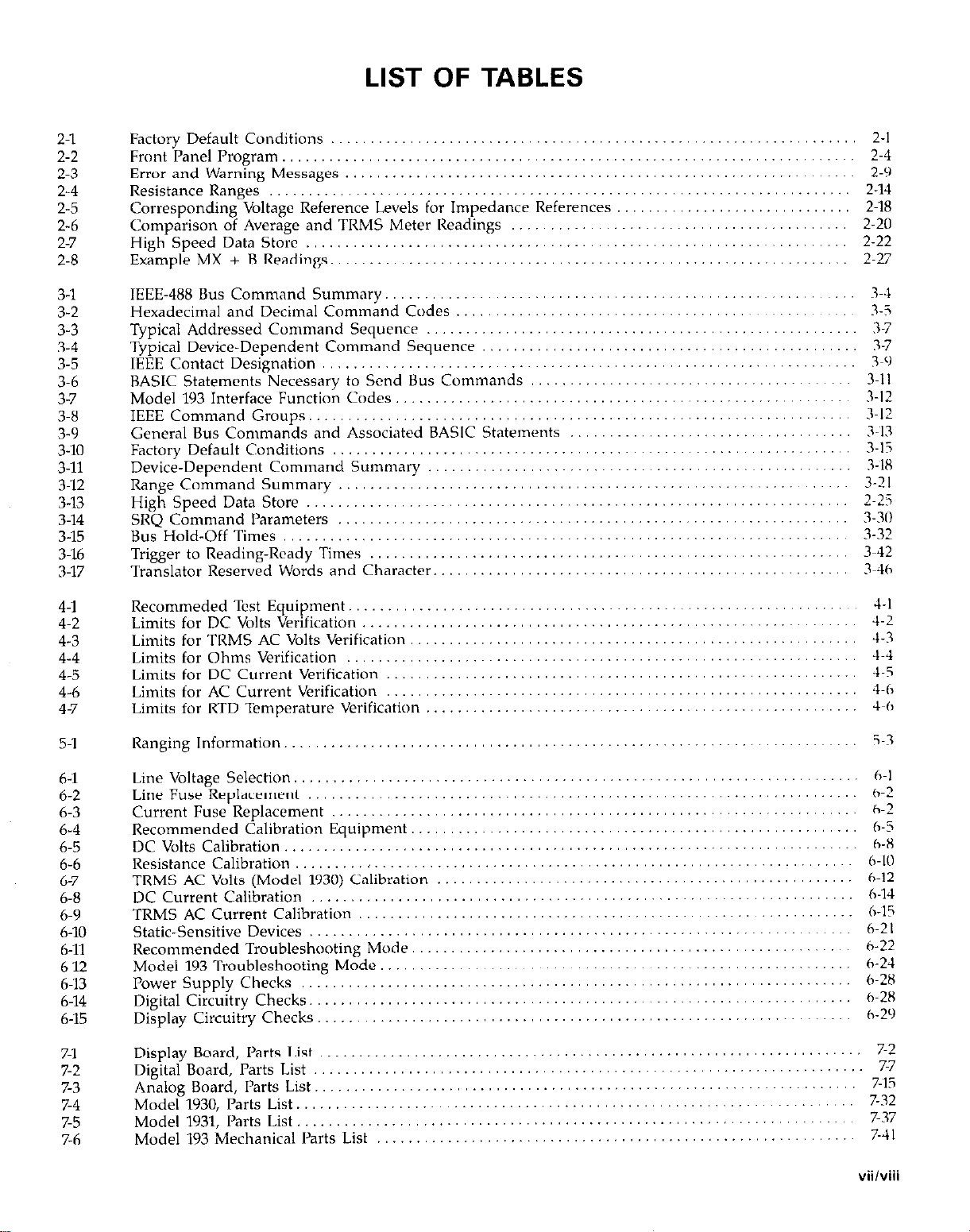
Factory Default Conditions
Front
Panel Program
Error and Warning Messages .................................................................
Resistance Ranges ..........................................................................
Corresponding Voltage Reference Levels for Impedance References
Comparison of Average and TRMS Meter Readings
High Speed Data Store
Example MX + BReadillgs ..................................................................
IEEE-488 Bus Command Summary
Hexadecimal and Decimal Command Codes
Typical Addressed Command Sequence
Typical Device-Dependent Command Sequence
IEEE Contact Designation
BASIC Statements Necessary to Send Bus Commands
Model 193 Interface Function Codes
IEEE Command Groups
General Bus Commands and Associated BASIC Statements
Factory Default Conditions
Device-Dependent Command Summary
Range Command Summary
High Speed Data Store .....................................................................
SRQ Command Parameters
Bus Hold-Off Times ........................................................................
Trigger to Reading-Ready Times
Translator Reserved Words and Character
.........................................................................
................................................................... 2-l
........................................... 2.20
..................................................................... 2.22
............................................................
...................................................
.......................................................
................................................ 3-7
....................................................................
......................................... 3-11
.......................................................... 7-12
.....................................................................
.................................... 3-U
.................................................................. 3-15
......................................................
................................................................. 3-21
.................................................................
.............................................................
..................................................... 3-46
2-4
2-9
2.14
.............................. 2-18
2.27
3-l
3-i
3-i
3-c)
3-12
R-18
2-Z
3-31)
3-32
3-42
4-l
4-2
4-3
4-4
4-5
4-6
4-7
5-l
h-l
6-2
6-3
6-4
6-5
b-b
6-7
6-8
6-9
6-10
6-11
6-12
6-13
6-14
6-15
7-l
7-2
7-3
7-4
7-5
7-6
Recommeded Test Equipment.
Limits for DC Volts Verification
Limits for TRMS AC Volts Verification
Limits for Ohms Verification
Limits for DC Current Verification
Limits for AC Current Verification
Limits for RTD Temperature Verification
Ranging Information
Line Voltage Selection
Line Fuse Replacement
Current Fuse Replacement
Recommended Calibration Equipment.
DC Volts Calibration
Resistance Calibration
TRMS AC Volts (Model 1930) Calibration
DC Current Calibration
TRMS AC $wnt Calibration
Static-Sensltwe Devices
Recommended Troubleshooting Mode.
Model 193 Troubleshooting Mode
Power Supply Checks
Digital Circuitry Checks ...........................................................................................................................................
Display Circuitry Checks
Display Board, Parts List
Digital Board, Parts List
Analog Board, I’arts List
Model 1930, Parts List
Model 1931, Parts List
Model 193 Mechanical Parts List
.........................................................................
.......
......................................................................
...................................................................... h-8
.........
.......................................................................
.......................................................................
...........
...........
.....
.............
........
........
...............
................
.......................................................... ..
,,
..........
..
.....................................................................
....................................................................
............
.....................................................................
.........................................................
.....
...................
.........................
.
.... ....... ..
....................
.....................
.....................
.....................
.....................
.....................
.....................
...
............................................. h-l
.
..................................................
........................................................
................................................... h-12
......................................................
.......................................................
........................................
.._
.
.................................................................................................
...........
............................... 7-41
.....
......
......
......
......
......
4-I
-1-2
4-3
4-4
4-5
4-h
4-h
5~3
h-2
h-2
h-5
6-K
::;:
1
h-2 I
h-22
h-24
f~:;;
h-29
;-;
7%
7-32
7-37
vii/viii
Page 16

Page 17

SECTION 1
GENERAL INFORMATION
1.1 INTRODUCTION
The Kcithlcy Model ~IYO System DMM, with thcTRMS AC
Volt ,Ind Current options installed, is ‘I six function
,tutora”ging digital multimeter. At 6% digit rcsc>lutio”, the
IID display cn” display +2,200,(100 counts. The rang? of
this anal[,g~to-digit,ll (ND) converter is gl-cater than the
nwmal +‘l,YYY,YYY count AID c”nwrtrr used in many 6%
digit DMMs. ‘l’hc built-in IEEE-48X interfax makes the instrument fully programmable ,,ver the IEEl:-4B8 bus. With
ihc ‘TRMS ACV option and the Current option installed,
the Model ~IY3 CJ” make the f~~llowing basic
measurements:
In addition to the above Imentioned mcaurcmcnt
capabilities, the Model ‘lY3 can “lake dB and TRMS AC
+ DC meaSu1’Cnw”tS.
1.2 FEATURES
Some important Model ‘lY3 features include:
l
14 Character Alphanumwic Display+‘asy t,, read 14
segment l.EDs used for readings and front panel
messages.
l
High Speed Measurement Ratc~‘lO00 readings per
second.
l
Zero-Used to cancel offsets or establish basclincs. A
zero value can be pmgrammcd from the front panel 01
over the IEEE-4X8 bus.
l
Filter-The weighted avcragc digital filter cd” bc set f”t
1 to YY readings from the front panel or <,ver the bus.
l
Data Store-An internal buffer that can store up t” 500
readings is accessible from either the front panel or <wt’r
the bus.
l
Digital Calibration-The instrument may bc digitally
calibrated from either the front panc’l or over the bus.
. User Programmable Default Qnditions-Any instru-
ment measurement configuration can be established as
1-l
Page 18

GENERAL INFORMATION
1.6 SPECIFICATIONS
Detailed Model 193 specifications may be found preceding
the Table of Contents of this manual.
l
Section 6 contains information for servicing the instrument. This section includes information on fuse replacement, line voltage selection, calibration and
troubleshooting.
l
Section 7 contains replaceable parts information.
1.7 INSPECTION
The Model 193 System DMM was carefully inspected, both
electrically and mechanically before shipment. After un-
packing all items from the shipping carton, check for any
obvious signs of physical damage that may have occurred
during transit. Report any damage to the shipping agent.
Retain and use the original packing materials in case
reshipment is necessary. The following items are shipped
with every Model 193 order:
Model 193 System DMM
Model 193 Instruction Manual
Safety Shrouded Test Leads
Additional accessories as ordered.
If an additional instruction manual is required, order the
manual package (Keithley Part Number 193-901-00). The
manual package includes an instruction manual and any
apphcable addenda.
1.8 USING THE MODEL 193 MANUAL
This manual contains information necessary for operating
and servicing the Model 193 System DMM, TRMS ACV
option and the Current option. The information is divided into the following sections:
l
Section 1 contains general information about the Model
193 including that necessary to inspect the instrument
and get it operating as quickly as possible,
l
Section 2 contains detailed operating information on using the front panel controls and programs, making connections and basic measuring techniques for each of the
available measuring functions.
l
Section 3 contains the information necessary to connect
the Model 193 to the IEEE-488 bus and program operating
modes and functions from a controller.
l
Section 4 contains performance verification procedures
for the instrument. This information will be helpful if
you wish to verify that the instrument is operating in
compliance with its stated specifications.
l
Section 5 contains a description of operating theory.
Analog, digital, power supply, and IEEE-488 interface
operation is included.
1.9 GETTING STARTED
The Model 193 System DMM is a highly sophisticated instrument with many capabilities. To get the instrument up
and running quickly use the following procedure. For com-
plete information on operating the Model 193 consult the
appropriate section of this manual.
POWW-Up
1. Plug the line cord into the rear panel power jack and
plug the other end of the cord into an appropriate,
grounded power source. See paragraph 22.1 for more
complete information.
2. Press in the POWER switch to apply power to the instrument. The instrument will power up to the XXIOVDC
range.
Making Measurements
1. Connect the supplied safety shrouded test leads to the
front panel VOLTS HI and LO input terminals. Make
sure the INPUT switch is in the out (FRONT) position.
2. To make a voltage measurement, simply connect the input leads to a DC voltage surge (up to 1OOOV) and take
the reading from the display.
3. To change to a different measuring function, simply
press the desired function button. For example, to
measure resistance, press the OHMS button.
Using
Storing Data:
1. Press the DATA STORE button. The DATA STORE in-
2. Select an interval, other than 000.000, using the 4 and
3. Press the ENTER button. The buffer sire will be
4. If a different buffer size is desired, enter the value us-
5. Press the ENTER button to start the storage process,
Data Store
dicator will turn on and a storage rate (in seconds) will
be displayed.
), and data buttons.
displayed. Size 000 indicates that data will overwrite
after 500 readings have been stored.
ing the number buttons (0 through 9).
l-2
Page 19

GENERAL INFORMATION
The data store mode can bc exited at any time before the
start of the storage process by pressing the RESET button.
Once storage has commenced, the storage process can be
stopped by pressing any function button. See paragraph
2.7.1 for complete information on storing data.
Recalling Data:
1. Press the RECALL button. The buffer location of last
stored reading will be displayed.
2. To read the data at a different memory location, enter
the value using the number buttons (O-9).
3. Press the ENTER button. The reading and the memory
location will be displayed.
4. The A and V buttons can be used to read the data in
all filled memory locations.
5. ‘To read the highest, lowest and average reading stored
in the buffer, press the number 1, 2 and 3 buttons
respectively. Note that the memory location of the
highest and lowest reading is also displayed. The
average reading is displayed along with the number of
readings averaged.
The recall mode can be exited by pressing the RESET button. See paragraph 2.7.2 for complete information on data
recall.
Using Front Panel Programs
I’mgram selection is accomplished by pressing the PRGM
button followed by the button(s) that corresponds to the
program number or name. For example, to select Program
93 (IEEE status), press the PRGM button and then 9 and
1 buttons. Table 2-2 lists and briefly describes the available
front panel programs. Once a program is selected the
following general rules will apply:
1. A displayed program condition can be entered by pressing the ENTER button.
2. Program conditions that prompt the user with a flashing
digit can be modified using the data buttons (0 through
9 and *) and the cursor control buttons (manual range
buttons).
3. Programs that contain alternate conditions can be
displayed by pressing one of the manual range buttons.
Each press of one of these buttons toggles the display
between the two available conditions.
4. A program will be executed when the pressed ENTER
button causes the instrument to exit the program mode.
5. A program can be exited at any time and thus not executed, by pressing the RESET button.
Paragraph 2.8 provides the dctailcd inform,ltion for “sing
the front paw1 programs.
1.10 ACCESSORIES
The following accessories are available to c~nhancr the
Model 193% capabilities.
ModcJ l6OOB High Voltage J’robc-The Model Jhl)l)l% CAtends DMM measurements to 4OkV.
Model 1641 Kelvin Test Lead Set-The Model 1641 has
special clip leads that allow 4.terminal measurements to
be made while making only tvw connections.
Model 1651 SO-Ampere Current Shunts-l‘hr h,Judcl I651 is
an external O.OOlR *l% 4-terminal shunt, \\hich pwmits
current measurements from 0 to SOA AC or DC.
Model ~1681 Clip-On Test Lead Set-l’hc Model I681 cow
tains two leads, 1.2m (48’) long terminated with banana
plugs and spring action clip probes.
Model 16R2A RF Probe-The Model 1682A permits voltage
measurements from ~IOOkIiz to 250MHz. AC to IX transfw
accuracy is -tldB from 1OOkHz to 25OMHz at IV, peak
responding, calibrated in I<MS of d sine \\‘ave.
Model ~1751 Safety Test JLcads-J’his test Icad SC~ is supplied
with every Model 193. Finger guards and shnrudcd banxu
plugs help minimize the chance of making contact with
live circuitry.
1-3
Page 20

GENERAL lNFORMAT,ON
is installed, AC + DC voltage measurements can bc made.
Field installation 01’ r~movallrcplacement of the Model 1930
will require recalibration of the Model 143 and the Model
lY30.
Model 193~1 Current Option--The Model 1931 is a plug-in
current option for the Model 793. This option allows the
instrument to measure DC current up to 2A. When both
Models lY30 and 1931 are installed, the instrument can
make TRMS AC current measurements and TRMS AC +
DC curi-ent meas”re”le”ts. Field installation requires
recalibration of the Model 193.
Model ~I938 Fixed Rack Mount-The Model ~1938 is a stationary mount kit that allows the Model 193 tube mounted
in a standard 19 inch rack.
Model 1939 Slide Rack Mount-l‘he Model 1939 is a sliding
mount kit that allows the Model 193 to be rack mounted
with the added feature of sliding the instrument forward
for cay access to the rear panel and top cover.
Model 7007 IEEE-488 Shielded Cables-The Model 7007
connects the Model 193 to the IEEE~488 bus using shielded cables to reduce electromagnetic interference (EMI). The
Model 7007-1 is one meter in length and has a EMI shirlded IEEE-488 wnnector at each end. The Model 7007.2 is
identical to the Model 7007-1, but is two meters in Icngth
Model 7008 IEEE-488 Cables-l’he Model 7008 connects the
Model 193 to the IEEE-488 bus. ‘The Model 7008-3 is 0.9m
(3 ft.) in length and has a standard IEEE-488 connector at
each end. ‘I‘hc Model 71108-6 cable is identical to the Model
7008.3, but is ~l.Hm (6 ft.) in length.
Model 8573 lEEE~488 Interface-~-rhr Model 8373 is an
IEEE-488 standard intcrfacc designed to interface the IBM
PC or X1‘ computers to Keithlcy instrumentation over the
IEEE-488 bus. The interface system contains two distinctive parts: an interfacr board containing logic to perform
the necessary hardware functions and the handler software (supplied on disk) to perform the rquircd control
functions. Thcsc twu important facets of the Model 8573
join together to give the IBM advanced capabilities over
IEEE-488 interfaceable instrumentation.
1-4
Page 21
SECTION 2
BASIC DMM OPERATION
2.1 INTRODUCTION
Operation of the Model 193 may be divided into two
general categories: front panel operation and IEEE-488 bus
operation. This section contains information necessary to
use the instrument from the front panel. These functions
can also be programmed over the IEEE-488 bus, as described in Section 3.
2.2 POWER UP PROCEDURE
2.2.1 Line Power
Use the following procedure to connect the Model 193 to
line power and power up the instrument.
1. Check that the instrument is set to correspond to the
available line power. When the instrument leaves the
factory, the internally selected line voltage is marked on
the rear panel near the AC power receptacle. Ranges are
105V.125V or ZlOV-250V 50160Hz AC. If the line voltage
setting of the instrument needs to be changed, refer to
Section 6, paragraph 6.2 for the procedure. If the line
frequency setting of the instrument needs to be checked
and/or changed, utilix front panel Program 92 (see
paragraph 2.8.11) after the instrument completes the
power-up sequence.
2. Connect the female end of the power cord to the AC
receptacle on the rear panel of the instrument. Connect
the other end of the cord to a grounded AC outlet.
WARNING
The Model 193 is equipped with a 3-wire power
cord that contains a separate ground
is designed to be used with grounded outlets.
When proper connections are made, instrument
chassis is connected to power line ground.
Failure to use a grounded outlet may result in personal injury or death because of electric shock.
wire
and
2.2.2 Power-Up Sequence
The instrument can bc turned on bv pressing i” the front
panel POWER switch The switch !$:ill bc at the inner most
position when the instrument is turned 01,. LJpcrn powerup, the instrument will dn a number of tests on itself. ‘rests
are performed on memory (ROM, RAM and NVRAM). If
RAM or ROM fails, the it~strument will lock up. If E’PROM
FAILS, the message “UNCALIBRATED” will be displayed.
See paragraph 6.9.2 for a complete description of the
power-up self test and recommendations to resolve
failures.
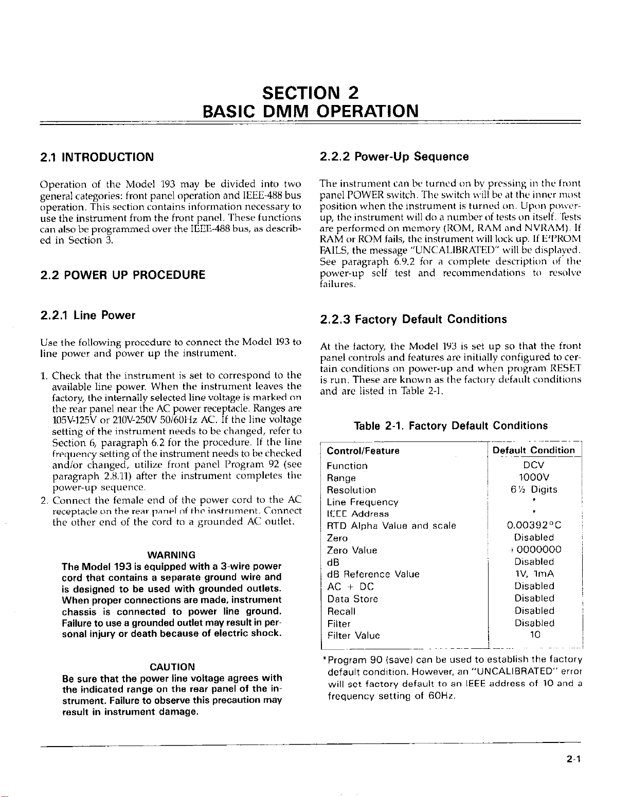
2.2.3 Factory Default Conditions
At the factory, the Model 193 is set up so that the front
panel controls and features are initially configured to cer-
tain conditions on power-up and when program RESET
is run. These are known as the factory default conditions
and are listed in Table 2-l.
Table 2-l. Factory Default Conditions
Control/Feature
Function
Range
Resolution
Line Frequency
IEEE Address
RTD Alpha Value and scale
Zero
Zero Value
dB
dB Reference Value
AC + DC
Data Store
Recall
Filter
Filter Value
Default Condition
DCV
1ooov
6% Digits
f
.
0.00392~C
Disabled
~l0000000
Disabled
IV, 1mA
Disabled
Disabled
Disabled
Disabled
10
CAUTION
Be s.ure that the power line voltage agrees with
the indicated range on the rear panel of the instrument. Failure to observe this precaution may
result in instrument damage.
*Program 90 (save) can be used to establish the factory
default condition. However, an “UNCALIBRATED” error
will set factory default to an IEEE address of 10 and a
frequency setting of 60Hr.
2-l
Page 22

OPERATION
2.2.4 User Programmed Conditions
A unique feature of the Model ~193 is that each function
“remembers” the last measurement configuration that it
was set up for (such as range, zc’ro value, filter value, ctc).
Switching back and forth betcveen functions will not alfeet the unique configuration of each function. Howcwr,
the instrument wili “forget” Ihc configurations on
pw”-dmvn.
Certain configurations can be saved by utilizing front panel
I’rugram 90. On power-up, thcsc user saved default c(,m
ditions will prevail over the factory default conditions.
Also, a DCI. (lr SDC asserted over the IEEE-4HH bus will
set the instrument to the user saved default conditions.
For more information, see paragraph 2.X.9 (I’rugram YO).
NOTE
Keep in mind that power-up deiault conditions
can br either factory default a,nditions or LISCI
saved default conditions.
2.3 FRONT PANEL FAMILIARIZATION
‘The front panel layout of the Model 1Y3 is shown in Figure
2~1. ‘The following paragraphs describe the various consponents of the front panel in detail.
POWER-The POWER switch cont~rols AC power to the instrument. Depressing and releasing the switch once turns
the power on. Depressing and releasing the switch a second time turns the power off. The correct positions for
on and off are marked on the front panel by the POWER
switch
INPUT~Thc INPUT switch connwts thcz instrument to
either the front panel input terminals (lr the war panel in-
put terminals. This witch oprrates in same manner as the
power switch. The front panel input tcmminals arc selected
when the switch is in the “out” position and the rear panel
input terminals art’ sclcctcd when the switch is in the “in”
pmition.
FUNCTlON GROUP-I’he FUNCI‘ION buttons are used
to s&cl the primary mcasurcment functions of the instru-
ment. Thcsc buttons rllsu have wwndwy functions.
DCV--The DCV button places the instrument in the DC
volts measurement Imodc. The secondary function of this
button is to enter the number 0. Set paragraph 2.h.4 iw
DCV measurements.
AC&With the ACV option installed, the ACV button
places the instrument in the AC volts measurcmcnt mode.
The secondary function of this button is to enter the
number I. See paragraph 2.66 for ACV mcasurcmcnts.
2.3.1 Display and Indicators
IXsplay-The 14 character, alphanumeric, LED display is
used to display numeric conversion data, range and function mnemonics (ix. mV) and messages.
Status Indicators-These three indicators apply to instrum
ment operation over the IEEE-488 bus. The REMOTE illdicator shows when the instrument is in the IEEE-488
remote state. ‘The TALK and LISTEN indicators show when
the instrument is in the talk and listen states respectively.
See Section 3 for detailed information on operation over
the bus.
2.3.2 Controls
All front panel controls, except the POWER and INPUT
switches, are momentary contact switches. Indicators are
located above certain feature buttons to show that they are
enabled. Included arc AUTO (autorange), ZERO, FILTER,
RECALI. and DATA STORE. Some buttons have secondary
functions that are associated with front panel program
operation. See paragraph 2-8 for detailed information on
front panel programs.
OHMS-The OfiMS button places the instrument in the
ohms measurement mode. The sccondnry function c)f this
button is to enter the number 2. See paragraph 2.6.7 fat
resistance measurements.
ACA-With the ACV option and current option installed,
the ACA button places the instrument in the AC amps
measurement mode. The secondary function of this button is to enter the number 3. See paragraph 2.6.8 for ACA
measurements.
DC-With the current option installed, the DCA button
places the instrument in the DC amps measurement mode.
The secondary function of this button is to enter the
number 4. See paragraph 2.6.8 for DCA mrasurcments.
TEMP--‘The TEMP button places the instrument in the RTD
temperature measurement mode. The secondary functions
of this button are to select the TEMI’ program (select alternate alpha value and thermometric scale) and to enter the
number 5. See paragraph 2.6.9 for RTD temperature
measureme”ts.
RANGE GROUPLl’he Aand vbuttons are used for
manual ranging and the AUTO button is used fat
autoranging. These buttons also have secondary iunctions.
2-2
Page 23

OPERATION
Manual-Each tinxe the A button is pressed, the instrument will mow up one range, while the r button will
move the instrument down one range each time it is
pressed. Pressing either of these buttons will cancel
autorange, if it was previous selcctcd. The secondary func-
tions of these buttons are associated with front panel pro-
gram operation.
AUTO-The AUTO button places the instrument in the
autorange mode and turns on the AUTO indicator. While
in this mode, the instrument will go to the best range to
measure the applied signal. Autoranging is available for
all functions and ranges. Autoranging may bc cancelled
by pressing the AUTO button or one of the manual range
buttons. The secondary function of this button is to enter
the + sign.
MODIFIER GROUP-The MODIFIER buttons activate
features that arc used to enhance the nwasurcment
capabilities of the Model 193. These features in effect
modify the selected function. In addition to their primary
tasks, these buttons have secondary functions.
ZERO-The ZERO button turns on the ZERO indicator
and causes the displayed reading to be subtracted from
subsequent readings. This feature allows for zer” correction or storage of baseline values. The secondary function
of this button is to select the ZERO program. Refer to
paragraph 2.6.2 for detailed information on the zero
feature.
dB-The dB button places the instrument in the dB
measurement mode and may be used with the ACV and
ACA functions. Under factory default conditions,
measurements are rcfcrenced to 1V or ImA. Howwer, the
dB program may be used to change the reference level.
The secondary function of this button is to select the dB
program. See paragraph 2.6.10 for dB measurements.
FILTER-The FILTER button turns on the FILTER in-
dicator and causes the instrument to start weighted
averaging a number (l-99) of readings. The factory default
value is 10, but may be changed using the FILTER pro-
gram (see paragraph 2.8.6). See paragraph 2.6.3 for filter
operation. Selecting the FlLTER program is one of the
secondary functions of this button. The other secondary
function is to enter the number 6.
AC + DC-With the appropriate options installed, the AC
+ DC button (with ACV selected) places the instrument
in the AC + DC measurement mode. With the ACV option installed, VAC + DC measurements can be made.
With both the ACV and current option installed, AAC iDC measurements can be made. See paragraph 2.6.12 for
AC + DC measurements. The secondary functions of this
button are to select the AC + DC program (low frequen-
cy TRMS measurements) and to enter the number 7.
CONTROL GROUP-The CONTROI~. buttons llr<’
features that allow for the control and m;tniplil.lti~~n i,i
various aspects of instrument “peraticrn. All of these but-
tons, except I’RGM, have II secondxy function
RESOl.N-The RES0I.N button ;tll~n\,s for the s&ctiiu~
of the number of digits of displdy rrsolutim~. Each pwss
of the RESOLN button incr11~~scs resolution by one digit.
Pressing the RESOLN button after the m<lkimum wsolw
tion is reached will revert the display back tu the I(,wcst
resolution. Display resolution of 3%. 4112, 5% (Ir 6% digits
can be selected for DCV and ACV. Display wwlution ot
4% or 5% digits can be selected for DCA and ACA On
OIIMS, 3’12, 4% 5% and 6% digit rtw,luti<~” is Ilvl~ill~bl~~
on the 20011 through 2OOkll ranges. 0” the 2h,ll! .l”d ?i)hl!!
ranges, 5% and 6% digits can bc sc~lc~cted. On the ?llOhl!!
range, only 5%d resoluti~,n is av~ilablc. .The RI~SOI..~ bul-
ton has “~, effect on I”\%, freqwwy ,\C i DC (I’rogrdnl
AC + DC), ‘TEMP or dB measurcnwnts. l’hc wcondx\
function of this button is to enter lhc dccinul puint (.i.
TRIGGER/ENTER-The TRIG(;ERiENTlill butti~n is used
as a terminator fur data entry when the instrumwt is i”
the front panel progrxn mode and 11s a front p.mel trig:
ger when the data stow is xtive.
STATUSIRESE-l
STATUS-lnstrumcnt status c.1” bc displwd \vhcrr th<,
instrument is in the normal measurclncnt &,dc or Iogging readings. When the STA’I’US button is first pressed
the following current instrument conditi~,ns ca” be
displayed with the use of the A and v buttons:
Software rcvisio” level
IEEE address
Line frequency setting
Multiplexer status (on/off)
MX+B status (on/off)
MX+B values
dB reference value
Filter value (OO=filter disabled)
Zen1 status (on!off)
Zero value
Pressing the STATUS button a scctmd time takes the ill-
strument out of the status mode.
RESET-The RESET button is used to reset the instrument
back to the previously entered paranwtcr. Keyed in
parameters are only entered after the ENTER button is
pressed. If RESET is pressed with the last p‘lramrter (It
a program displayed, the program will be exited and the
instrument will return to the previous clperating state. This
button aborts back to normal “pcr.ltion when it is i” 0111’
of the following modes:
2-3
Page 24
OPERATION
1. The data store is prompting for paramckrs (interval or
size).
2. The instrument is in the RECALL mode.
3. A front panel program has been selected (except Program AC+DC which is treated as a normal mcasure~
ment function (see STATUS).
Program RESET--Program RESET returns the instrument
to the factory default conditions. See paragraph 2.8.7 for
information on using this program.
DATA STORE-The DATA STORE button s&c& the 500
point data store mode of operation Paragraph 2.7 contains
a complete description of data store operation. The secondary function uf this button is to enter the number 9.
RECALLJhe RECALL button recalls and displays
readings stored in the data stow Paragraph 2.7.2 provides
a detailed procedure for recalling data. The secondary
function of this button is to enter the number 8.
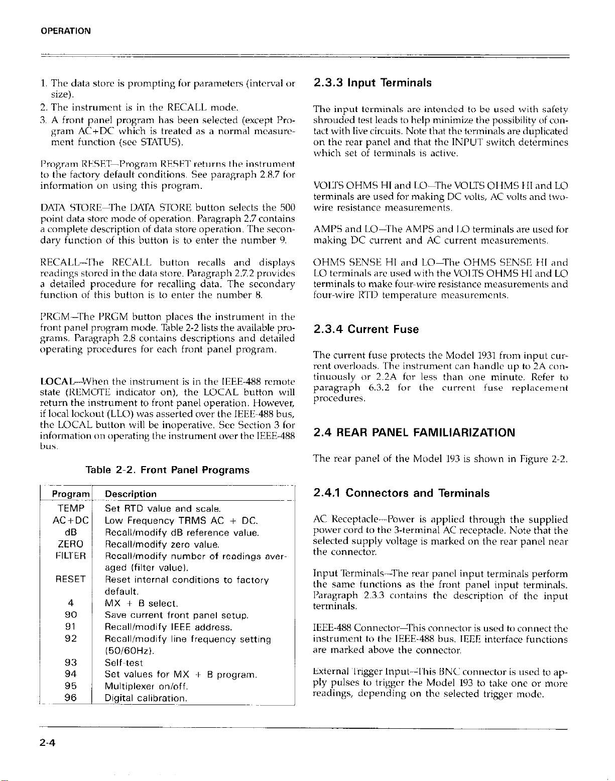
I’RCM-The PRGM button places the instrument in the
front panel program mode. Table 2-2 lists the available pro@xns. Paragraph 2.8 contains descriptions and detailed
operating pnwzdures for each front panel pn,gram.
LOCAL-When the instrument is in the IEEE-488 remote
state (REMOTII indicator on), the LOCAL button will
return the instrument to front panel operation. However,
if local lockout (LLO) was asserted over the IEEE-488 bus,
the LOCAL button will be inoperative. SW Section 3 for
information on uperating the instrument over the IEEE-488
bus.
Table 2-2. Front Panel Programs
2.3.3 Input Terminals
The input terminals are intended to be used with safety
shrouded test leads to help minimize the possibility of con-
tact with live circui&. Note that the twninals are duplicated
on the rear panel and that the INPUT switch determines
which set of terminals is active.
VOI:l’S OHMS HI and I>O-The VOLTS OHMS 111 and LO
terminals are used for making DC volts, AC volts and tww
wire resistance measurements.
AMPS and LO-The AMPS and 1.0 &rminals are used for
snaking DC current and AC current nwasurcmcnts.
OHMS SENSE HI and LO-The OHMS SENSE ktl and
LO terminals arc used with the VOIDS OHMS HI and LO
terminals to make four-wire resistance measurements and
four-wire liTI1 temperature measurcnwnts.
2.3.4 Current Fuse
The current fuse protects the Model lY31 from input current overloads. The instrument can handle up lo 2A cow
tinuously or 2.2A for less than one minute. Refer tu
paragraph 6.3.2 for the currcnl fuse replacement
procedures.
2.4 REAR PANEL FAMILIARIZATION
The rear panel of the Model 7Y3 is shown in Figure 2.2.
Progran
TEMP
AC+DC
ZERO
FILTER
RESET
2-4
dB
4
90
91
92
93
94
95
96
Description
Set RTD value and scale.
Low Frequency TRMS AC + DC.
Recall/modify dB reference value.
Recall/modify zero value.
Recall/modify number of readings averaged (filter value).
Reset internal conditions to factory
default.
MX + B select.
Save current front panel setup.
Recall/modify IEEE address.
Recall/modify line frequency setting
l50160Hz).
Self-test
Set values for MX + B program.
Multiplexer on/off.
Digital calibration.
2.4.1 Connectors and Terminals
AC Receptacle-Power is applied through the supplied
power cord to the 3.terminal AC receptacle. Note that the
selected supply voltage is marked on the rear panel “ear
the connector.
Input Terminals-The rear panel input terminals perform
the sane functions as the front panel input terminals.
Paragraph 2.3.3 contains the description of the input
terminals.
IEEE-488 Connector-This connector is used to connect the
instrument to the IEEE-488 bus. IEEE interface functions
are marked above the connector.
External Trigger Input-This BNC connector is used to apply pulses to trigger the Model 193 to take one or more
readings, depending on the selected trigger mode.
Page 25

OPERATION
Voltmeter Complete Output-This BNC output connector provides a pulse when the Model lY3 has completed
a reading. It is useful for triggering other instrumentation.
2.4.2 Calibration Switch
Calibration of the Model 193 can only be done if the
calibration switch is in the unlock position.
2.4.3. Line Fuse
The line fuse provides protection for the AC power line
input. Refer to paragraph 6.3.1 for the line fuse rcplacrment procedure.
2.5 ERROR AND WARNING DISPLAY
MESSAGES
Table 2-3 lists and explains the various display rncss~~~~~s
associated with incorrect front pancl opcraiion ot the
Model 193. Also included is a warning mcssagc that illdicates tu the user that hazardous \wltages (WV or nww)
are present on the input termin‘lls.
Z-5/2-6
Page 26

Page 27

OPERATION
-
I,/ I, T T i--l I
I, \/
I\I-r l I II,I- I
I I,-,I ,-,I
I I-l
\
-REAR
/
Figure 2-l. Model 193 Front Panel
-
-
-
-
Figure 2-2. Model 193 Rear Panel
Z-712-8
Page 28

OPERATION
Table 2-3. Error and Warning Messages
Message
NEED 1930 Selected option not installed.
NEED 1931
NEED 1930.1931
“H” High Voltage: 40V or more on
NO PROGRAM
O.VERFLO KOHM Overrange-Decimal point posi-
TRIG-OVERRUN Trigger received while still pro-
CONFLICT Trying to calibrate with instrw
NOT ACV or ACA Selecting AC t DC or d6 with in-
Explanation
input.
Invalid entry while trying to
select program.
tion and mnemonics define
function and range (2kR range
shown). The number of
characters in the “OVERFLO”
message defines the display
resolution (6%d resolution
shown).
cessing reading from last
trigger.
ment in an improper state.
strument not presently in ACV
or ACA.
When making measurements in high energy circuits use
test leads that meet the following requirements:
l
Test leads should be fully insulated.
l
Only use test leads that can be connected to the circuit
(e.g. alligator clips, spade lugs, etc.) for hands-off
measurements.
l
Do not use test leads that decrease voltage spacing. This
diminishes arc protection and creates a hazardous
condition.
Use the following squence when testing power circuits:
1. De-energize the circuit using the regular installed
connect-disconnect device such as the circuit breaker.
main switch, etc.
2. Attach the test leads to the circuit under test. Use appropriate safety rated leads for this application.
3. Set the DMM to the proper function and range.
4. Energize the circuit using the installed connect-
disconnect device and make measurements without
disconnecting the DMM.
5. De-energize the circuit using the installed connect-
disconnect device.
6. Disconnect the test leads from the circuit under test.
2.6 BASIC MEASUREMENTS
The following paragraphs describe the basic procedures
for making voltage, resistance, current, temperature, dB,
and AC + DC measurements. An ACV option must be installed for ACV measurements, the current option must
be installed for DCA measurements and both options must
be installed for ACA and AAC + DC measurements.
High Energy Circuit Safety Precautions
To optimize safety when measuring voltage in high energy
distribution circuits, read and use the directions in the
following warning.
WARNING
Dangerous arca of an explosive nature in a high
energy circuit can cause severe personal injury
or death. If the meter is connected to a high
energy circuit when set to a current range, low
resistance range or any other low impedance
range, the circuit is virtually shorted. Dangerous
arcing can result even when the meter is set to
voltage range if the minimum voltage spacing is
reduced.
WARNING
The maximum common-mode input voltage (the
voltage between input LO and chassis ground) is
500V peak. Exceeding this value may create a
2.6.1 Warm Up Period
The Model 193 is usable immediately when it is first turned
on. However, the instrument must be allowed to wartn up
for at least one hour to achieve rated accuracy.
2.6.2 Zero
The zero feature serves as a means of baseline suppres-
sion by allowing a stored offset value to be subtracted from
subsequent readings. When the ZERO button is pressed,
the instrument takes the currently displayed reading as
a baseline value. All subsequent readings represent the dif-
ferences between the applied signal level and the stored
baseline.
2-9
Page 29

OPERATION
A baseline level can be established for any or all measurc-
rnent functions and is remembered by each function. For
example, a ‘IOV baseline can be established on DCV, a 5V
baseline can be established on ACV and a IOkR baseline
can be established on OHMS. These levels will not be
canccllcd by switching back and forth between functions.
Once a baseline is established for a measurement function, that stored level will be the same regardless of what
range the Model lY3 is on. For example, if 1V is established
as the baseline on the 2V range, then the baseline will also
bc IV on the XIV through ‘IOOOV ranges. A zero baseline
levrl can be as large as full range.
NOTE
The following discussion on dynamic range is
based on a display resolution of 6% digits. At 5%
digit resolution, the number of counts would be
reduced by a factor of 10. At 4%d resolution,
counts would be reduced by a factor of 100 and
3%d resolution would reduce counts by a factor
of 1000.
By design, the dynamic measurement range of the Model
~193, at 6% digit resolution, is 4400000 counts (excluding
the 1000VDC and 700VAC ranges). With zero disabled,
the displayed reading range of the instrument is ~2200000
counts. With zero enabled, the Model 193 has the capabili-
ty to display +4400000 counts. This increased display
range ensures that the dynamic measurement range of the
instrument is not reduced when using a zero baseline
value. The following two examples will use the maximum
allowable zero values (+2200000 counts and -2200000
counts) to show that dynamic measurement range will not
be reduced. It is important to note that the increased
display range does not increase the maximum allowable
input level to the instrument. For example, on the 2V
range, the Model 193 will always overrange when more
than +2.2V is connected to the input.
Example l-The instrument is set to the ZVDC range and
a maximum -2,200OOOV is established as the zero value.
When -2.2OOOOOV is connected to the input of the Model
193, the display will read O.OOOOOOV. When +2.2OOOOOV
is connected to the input, the display will read
+4.4OOOOOV. Thus, the dynamic measurement range of
the Model 193 is OV to 4.4V, which is 4400000 counts.
Example 2-The instrument is still set to the 2VDC range,
but a maximum +2,2OOOOOV is the zero level. When
+2,2OOOOOV is connected to the input of the Model 193,
the display will read O.OOOOOOV. When -2.2OOOOOV is connected to the input, the display will read -4.4OOOOOV. Thus
the dynamic measurement range of the instrument is -4.4V
to OV, which is still 4400000 counts.
Zero Correction-The Model 193 must be properly zeroed
when using the 200mV DC or the 20011 range in order to
achieve rated accuracy specifications. To use ZERO for
xcro correction, perform the following steps:
Disable zero, if presently enabled, by pressing the
ZERO button. The ZERO indicator will turn off.
Select the 200mV DC or the 2000 range.
Connect the test leads to the input of the Model ‘193
and short them together. If four-wire resistance
measurements are to be made, connect and short all
four leads together.
Note: At 5% and 6% digit resolution, low measurement
techniques need to be employed. Use Kelvin test leads
or shielded test leads. See paragraph 2.6.5 for low level
measurement considerations.
Press the ZERO button. The display will read zero.
Remove the short and connect the test leads to the
signal or resistance to be measured.
Note: Test lead resistance is also compensated for when
zeroing the 20011 range with the above procedure.
Baseline Levels-Baseline values can be established by
either applying baseline levels to the instrument or by set-
ting baseline values with the front panel ZERO program.
Paragraph 2.8.5 contains the complete procedure for us-
ing the ZERO program. ‘To establish a baseline level by
applying a level to the Model 193, perform the following
steps:
1.
Disable zero, if presently enabled, by pressing the
ZERO button. The ZERO indicator will turn off.
2.
Select a function and range that is appropriate for the
anticipated measurement.
3
Connect the desired baseline level to the input of the
I
Model 193 and note that level on the display.
Press the ZERO button. The display will zero and the
4.
ZERO indicator will be enabled. The previously
displayed reading will be the stored baseline. The zero
baseline value will also be stored in Program ZERO,
replacing the previous zero value.
WARNING
If +4OV or more is present on the input terminals, the Model 193 will display the mnemonic
“H” to indicate the presence of hazardous
voltage.
For example, the
display
“00.0000HVDC” indicates than of 40V or more
is present on the input.
Disconnect the stored signal from the input and con-
5,
nect the signal to be measured in its place. Subsequent
readings will be the difference between the stored value
and the applied signal.
2-10
Page 30

1. Disabling zero cancels the zero baseline value on that
selected function. However, since the zero value is
automatically stored in Program ZERO, the zero
baseline value can be retrieved by using the program
as long as the ZERO button is not again pressed (see
paragraph 2.8.5 for details). Pressing the ZERO button,
thus enabling zero, will wipe out the previous baseline
value in Program ZERO. Baselines established on other
functions are not affected.
2. To store a new baseline on a selected function, zero
must first be disabled and then enabled again. The new
value will be stored with the first triggered conversion.
The baseline value will also be stored as the zero value
in program ZERO, cancelling the previously stored
value.
3. Setting the range lower than the suppressed value will
overrange the display; the instrument will display the
overrange message under these conditions.
4. When the ZERO button is pressed to enable zero, the
zero indicator light will blink until an on scale reading
is available to use as a zero level.
OPERATION
filter value. For example, for a filter value if IO, one time
constant is equal to 10 readings and three time constants
would be equal to 30 readings. ‘The blinking duration
will be shorter in the 31id mode since th.at has the fast<zst
reading rate.
3. In a continuous trigger mode, a reading that is <,utsidc
the filter window will cause the filter indicator t<l blink
for one time constant.
Digital Filter-The Model 193 utilizrs ‘1 digit,11 filter tij ate
tenuate excess noise present on input signals. The filter
is a weighted average type. The mathematical rcprewn
tation is:
(new reading -AVG(t ~I))
AVG(t) = AVG(t-1) + ~.
r:
Where,
AVG(t) = displayed average
AVG(t - ‘I) = old displayed average
F = weighting factor (filter value)
2.6.3 Filter
When the filter is enabled, a number of measurements are
averaged before being displayed. The factory default
number is 10, but it can be changed to a value from 1
to 99 with the use of the FILTER program. A filter value
can be set for any or all measurement functions and is
remembered by each function. For example, a filter value
of 20 can be set for DCV and a filter value of 55 can be
set for ACV. These filter values will not be cancelled by
switching back and forth between functions.
An advantage of using the filter is to stabilize the reading
of a noisy input level. A consideration of filter usage is
that the larger the number of readings averaged, the
longer the response time of the display. Perform the
following procedure to use the filter:
1. If it is desired to check and/or change the filter value,
utilize Program FILTER as explained in paragraph 2.8.6.
2. Press the FILTER button. The FILTER indicator will turn
0”.
Notes:
1. Pressing the FILTER button a second time will disable
the filter.
2. After a reading is triggered (continuous or one-shot),
the filter indicator light will blink for three time constants. A time constant is measured in readings. The
number of readings in one time constant is equal to the
As with any filter, the Model 193 digital filter will affect
reading response time. The step response for this filter
is of the form:
step response = I- K(“+ ‘)
Where,
“K” is a constant based on the filter \veighting fact<>1
“n” is the reading number.
The step occurs ~‘hen n =O. II = 1 is th? first reading dftcr
the step, n=2 is the second reading, etc.
Therefore:
step response = 1 -
Example:
F = ‘IO
n=s
2.11
Page 31

OPERATION
Five readings after the step occurs, the display will be at
=47% of the step change. After 10 readings (n=IO), the
display will be at =68% and after 20 readings, the display
will be at =880/o. The mwe the readings, the closer the
display will be to the step change.
To speed the response to large step changes, the Model
lY3 digital filter employs a “window” around the
displayed average. As long as new readings are within
this window, the displayed value is based on the weighted
average equation. If a new reading is outside of this window, the displayed value will be the new reading, and
weighted avera#ng will start from this point. The step
response was one reading to this change. The window in
the Model 193 filter is 10,000 counts for 6%d resolution,
1000 counts for 5’12, 100 counts for 4% and 10 counts for
3 %
2.6.4 DC Voltage Measurements
The Model IY3 can be used to make DC voltage
measurements in the range of *lOOnV to i1OOOV. Use
the following procedure to make DC voltage
measurements.
‘I. Select the DC volts function by pressing the DCV
button.
2. Select a range consistent with the expected voltage or
use autorange.
3. Select the front or rear panel input terminals with the
INPUT switch.
4. Connect the signal to be measured to the selected input terminals as shown in Figure 2-3.
5. Take the reading from the display.
2.6.5 Low-Level Measurement Considerations
Accuracy Considerations-For sensitive measurements,
other external considerations besides the Model 193 will
affect the accuracy. Effects not noticeable when working
with higher voltages are significant in nanovolt and
microvolt signals. The Model 193 reads only the signal
received at its input; therefore, it is important that this
signal be properly transmit&d from the source. The
following paragraphs indicate factors which affect ac-
curacy, noise, wurcc resistance, thermal emfs and stray
pick-up.
Noise and Source Resistance-The limit of sensitivity in
measuring voltages with the Model ~193 is determined by
the noise mesent. The dis~laved noise is inherent in the
instrument and is present in all measurements. l’he II&P
voltage at the Model ~193 input increases with source
resistance..
For high impedance sources, the generated noise can
become significant when using the most sensitive range
(200mV. h%d) of the Model ‘193. As an examvlc of detcrmining & (n&c voltage generation due to Johnson noise
of the source resistance), assume that the Model 193 is corn
netted to a voltage source with an internal resistance of
IMI2. At a roum temperature of 2O”C, the p-p noise voltage
generated over a bandwidth of 1Hz will be:
NOTE
The 20OmV DC range requires ZEK to be set in
order to achieve rated accuracy. The zero correction procedure can bc found in paragraph 2.6.2.
Figure 2-3. DC Voltage Measurements
Z-12
Page 32

OPERATION
Thus, an er of 0.635pV would be displayed at 6%d resolution as an additional 6 digits of noise on the Model 193.
To compensate for the displayed noise, use digital filter-
ing and then zer” Out the settled offset.
Shielding-AC voltages which are extrcmcly large com-
pared with the DC signal may erroneously produce a DC
output. Therefore, if there is AC interference, the circuit
should be shielded with the shield connected to the Model
193 input LO (particularly fw l”w-level sources). Impmpel
shielding can cause the Model 193 t” behave in one or m”re
of the following ways:
1. Unexpected “ffsct voltages.
2. Inconsistent readings between ranges.
3. Sudden shifts in reading.
To minimize pick-up, keep the voltage source and the
Model 193 away from strong AC magnetic sources. The
voltage induced due to magnetic flux is proportional to the
area of the loop formed by the input leads. Therefore,
minimize the loop area of the input leads and connect each
signal at only one point.
Thermal EMFs-Thermal emfs (thermoelectric potentials)
are generated by thermal differences between the junction
of dissimilar metals. These can be large compared to the
signal which the Model 193 can measure. Thermal emfs
can cause the following problems:
1. Instability or zer” offset is much higher than expected.
2. The reading is sensitive to (and responds to)
temperature changes. This can be demonstrated by
touching the circuit, by placing a heat s”urce near the
circuit or by a regular pattern “f instability (corresponding to heating and air-conditioning systems or changes
in sunlight).
3. To minimize the drift caused bv thermal rmfs. USC
per leads to connect the c&it to the Model 193. ‘A
banana plug is generally suitable and gencrates just a
few microvolts. A clean copper conductor such as #lO
bus wire is about the best for this application. The leads
to the input may be shielded or unshielded, as
necessary. Refer to Shielding.
4
Widely varying temperatures within the circuit can also
create thermal emfs. Therefore, maintain constant
temperatures to minimize these thermal emfs. A cardboard box around the circuit under test also helps by
minimizing air currents.
5. The ZERO control can be used to null out constant oftset voltages.
COD-
2.6.6 TRMS AC Voltage Measurements
With the ACV option installed, the instrunwnt clln m&c
TRMS AC voltage mrasurenwnts fr<>m IwV to 7OOV. ‘lir
rneasu~~ AC volts, procced as f”llwvs:
3. Sclcct the front or rear panel input terminals using the
INl’U’l‘ switch.
NOTE NOTE
There is a small amount “f c)ffset (typically IS0 There is a small amount “f c)ffset (typically IS0
counts at S%d) present when using the ACV counts at S%d) present when using the ACV
function. Do not zero this level wt. I’arq,rdph function. Do not zero this level wt. I’arq,rdph
2.6.~13 pmvides an explanation “f AC voltage 2.6.~13 pmvides an explanation “f AC voltage
offset.
4. Connect the signal to bc measured t” the selected irr~
put terminals as shown in Figure 2-4.
5. Take the reading from the display.
Clarifications “f Model 1930 ‘TRMS ACV Specifications:
Settling Tim-0.5sec t” within 0. I% “f change in mading.
This time specification is for analog circuitry to settle and
does not include AID conversion time.
Crest Factor-Rated accuracy t” 3 at full scale for pulse
widths >70Psec and peak wltage < 1.5 x full scale. F<lr
crest factors >3 but < 10, typical accuracy is degraded ‘1~~
cording t” the f”ll”wing calculation
AD = (CF-3) x 0.36%
Where: AD is accuracy dcgradatiun
CF is the crest factor
Also, the peak signal must be less than 5 x full scale, but
not m”rc than the maximum input specification.
Notes:
1. See paragraph 2.6.13 for TRMS mcasuwmcnt
considerations.
2. For TRMS AC+DC measurements, see pxagraph 2.6.~12.
3. To make low frequency AC measurements in the range
of 10Hz to 2OHz:
A. The ACV option must bc installed.
B. The ACV function must be selected.
2-13
Page 33

OPERATION
C. Digital filtering must he used to obtain a stable
reading.
D. Allow enough settling time before taking the
reading.
4. 7’0 make low frequency voltage measurements in the
range uf il’ll1z t<, 10Hz, use I’mgram AC+DC (see
pqqaph 2.8.3). The ACV option does not have 1(, he
installed for these measurements.
2.6.7 Resistance Measurements
‘l’h~ Model ~193 can make resistance measurements from
‘lOOPII to 21lOM0. The Model ‘I93 pnwides automatic selection of 2-terminal or 4.terminal resistance measurements.
This means that if the ohms sense leads are not connected,
the measurement is done 2-terminal. if the scnw leads are
cwmccted, the measurement is done 4.terminal. For
4.terminal measurements, rated accuracy can be obtained
as lung as the maximum lead wsistancc does not exceed
the values listed in Table 2-4. Fw best results on the 20011,
2k0 and 2OkLl ranges, it is recommended that 4.terminal
mcasuremcnts be made to eliminate errors caused by the
voltage drop across the test leads which will occur when
2.terminal measurements are made. The Model ‘I641
Kelvin Test L.rad Set is ideal for Iwv resistance 4-terminal
measurements. ‘To make resistance measurements, prw
cwd as f~,llows:
1. Select the ohms function by pressing the OHMS button
2. Select a range consistent with the expcctrd resistance
or use autorange.
3. Select the front or rear panel input terminals using the
INPUT switch.
NOTE
The 20012 range recluircs wro to bc set in order
tu achieve rated accuracy. The KTO corrt‘ctiim
procedure can be found in paragraph 2.6.2.
4. For Z-terminal mcasurcments connecl the resistance t(,
the instrument ds shown in Figure 2-S. f+lr 4-trrmin;rl
meawr~ments connect the resistance TV, the instrument
as shown in Figurv 2-h.
CAUTION
The maximum input voltage between the HI and
LO input terminals is 350V peak or 250V RMS.
Do not exceed these values or instrument
damage may occur.
5. Take the reading from the display
r
Figure 2-4. TRMS AC Voltage Measurements
Table 2-4. Resistance Ranges
Current
6%d
Range Resolution Unknown
200 n 0.1mn
2 kfl ImR
20 kR IOmR
200 kfl 1 OOmR
2MO 1 0
20MR 10 R
200MQ 100 0
Through Resistance (111 for
ImA 1
1mA 3.2
lOOpA 10
lO+A 32
1 PA 100
100 nA 320
100 “A” lk
Maxim&Test Lead
< 1 Count Error (6%d)
Z-14
*Short circuit current only
Page 34

OPERATION
Notes:
Incorrect readings will result if the resistance being
measured is part of a live circuit.
Table 2-4 shows the current output for each resistance
range.
It helps to shield resistance greater than lOOk to
achieve a stable reading. Place the resistance in a shield-
ed enclosure and electrically connect the shield to the
LO input terminal of the instrument.
Diode Test-The 2k0 range can bc used to test diodes
follows:
Select the 2kR range.
Forward bias the diode by connecting the red terminal of the Model 193 to negative side of the diode.
A good diode will typically measure between 5000
to 1kO.
Reverse bias the diode by reversing the connections
on the diode. A good diode will overrange the
display.
.*
I I
I- ----- ----- - --- l *
MODEL 193
------ l
CAUTION: MAXIMUM INPUT
2.6.8 Current Measurements (DC or TRMS AC)
With the Model 1931 Current option installed, the Model
193 can make DC current mcasuremt‘nts from InA [at ?‘!2d
resolution) to 2A. The same range of TRMS AC’ current
measurements can be made if both the current xxi AC’\’
options are installed in the instrument. USC the i&wing
procedure to make current measurements.
1. Select the DC current or AC current function by pressing the DCA or ACA button respectively.
2. Select a range consistent with the expected curwnt or
use autorangc.
3. Select the front or rear panel input tt’rminals uing the
INPUT switch.
4. Connect thr signal to be mcdsurtxi to the sclccted ills
put terminals as shown in Figuw 2-7.
5. Take the reading from the displ,ly.
SHIELDED CABLE
/\
‘_I
I
\ I
350” PEAK OR 250” HMS
.
OPIIONA, SHltl L1
I--- --------I
1
RtSISIANCE 1
UNDtn TkST ,
L--------J
I
I
I
Figure 2-5. Two-Terminal Resistance Measurements
------
I - - - - _ _ _ _ _ - - - - - - .
MODEL 193
CAUTION: 350” PEAK OR 250” RMS
Figure 2-6. Four-Terminal Resistance Measurements
OPTIONAL SHIELD
i---------y
I
.
RESiSTANCE ,
I
I
I
L------d
Z-15
Page 35

OPERATION
Figure 2-7. Current Measurements
2.6.9 RTD Temperature Measurements
The Model 193 can make temperature measurements from
-100” to +63O”C (-148” to +llOO”F) using platinum RTD
sensors. Resolution is 0.01 “C or OF. The front panel TEMP
program allows the user to select the alternate alpha value
(0.00385 UT 0.00392) and the alternate thermometric scale
(“C or “F). See paragraph 2.8.2 for detailed information
for using the TEMP program. Use the following procedure
to make RTD tcmperaturc measurements.
7. Select the RTD temperature function by pressing the
TEMP button.
2. The instrument will now display one of the following
readings:
OVERFL “C PRTD or OVERFL OF PRTD
The display is overranged at this time because an RTD
scnwr is not yet connected to the input. The OF or “C
indicates the current thermometric scale and PRTD indicates the measurement mode (platinum resistance
temperature device).
3. To check and/or change the alpha value or thermometric
scale, utilize the TEMP program (see paragraph 2.8.2).
4. Select the front or rear panel input terminals with the
INPUT switch and connect the platinum RTD sensor
to the instrument as shown in Figure 2-8.
5. Take the reading from the display
NOTE NOTE
With additional instrumentation, the Model 193 With additional instrumentation, the Model 193
has the capability of making temperature has the capability of making temperature
measurements usiw thermocouple (TC) scnsws. measurements usiw thermocouple (TC) scnsws.
Selection of the vari&s TC mod& c;n only be ac-
complished over the IEEE-488 bus. See paragraph
3.10.22 for more information.
Z-16
Figure 2-8. RTD Temperature Measurements
Page 36

OPERATION
2.6.10 dB Measurements
The dB measurement mode makes it possible to compress
a large range of measurements into a much smaller scope.
AC dB measurements can be made with the instrument
in the ACV or ACA function. The relationship between dB
and voltage and current, can be expressed by the following equations:
At the factory the instrument is set up to be a dBV meter
when ACV dB is selected. dBV is defined as decibels above
or below a IV reference. The instrument will read OdB
when 1V is applied to the input. The 1V reference is the
factory default reference and is indicated on the display
by the “V” mnemonic. Thus, whenever “dBV” is displayed,
the operator will know that the reference is 1V. With ACA
dB selected, the factory default reference is 1mA. The in-
strument will read OdB when 1mA is applied to the input.
AC dB Measurements-Perform the following steps to
make dB measurements:
1.
Select the ACV or ACA function.
2.
Select the front or rear panel input terminals with the
INPUT switch.
Check and/or change the dB reference as previously
3.
explained.
Connect the signal to be measured to the input of the
4.
Model 193.
5
If AC + DC dB measurements arc to be made, pwss
_.
the AC + DC button.
Note: DC dB measurements can be made by selecting
the AC + DC modifier as long ‘1s there is no AC ctmlponent present on the input signal.
Enable the dB measurement mode by pressing the dB
6.
button.
7.
Take the dB wading from the display.
WARNING
If 40V or more is present on the input terminals.
the Model 193 will display the the mnemonic
“Ii” to indicate the presence of hazardous
voltage. For example. the display “60.00 d6V Ii”
indicates that 40V or more is present on the
input.
Reference levels other than 1V and 7mA can be established.
There are two methods that can be used to establish a dB
reference. One method is to use the zero feature. This
simply consists of applying a signal to the instrument and
pressing the ZERO button. That suppressed level is the
dB reference (OdB point). The alternate method is to utilize
the front panel dB program and enter the desired reference
value. An advantage of using the dB program is that a
source is not needed to establish a reference.
The following procedure explains how to use the zero
feature to establish a reference:
1. Apply a voltage or current signal, that is to be used as
the dB reference, to the input of the Model 193.
2. Press the ZERO button. The ZERO indicator will turn
on and the display will zero. The reference is now
whatever the applied signal is.
3. Disconnect the signal from the instrument.
Program dB allows the the user to check or change the dB
reference of the instrument. The recommended programmable voltage reference range is from 1OpV to 9.99999V. The
recommended programmable current reference range is
from 1OnA to 9.99YY9mA. Paragraph 28.4 contains the information needed for using the dB program.
The following information explains the displayed
mnemonics that are associated with dB m~asurc’mc”ts:
dBV = dB voltage measurement mode with the dB
reference at 1v.
dB = dB voltage measurement mode.
dBA = dB current measurement mode. Unlike dBV, this
message does not define the dB reference.
dBV A+D = AC+DC dB voltage measurement mode with
1v reference.
dB A+D = AC+DC dB voltage measurements.
dBA A+D = AC+DC dB current measurement mode.
H = High VUtage: 40V or more D” input. This m”c’“wnic
could be displayed with any of the above messages.
dBm Measurements-dBm is defined as decibels above or
below a 1mW reference. dB measurements can be made
in terms of impedance rather than voltage or current.
Because the instrument cannot directly establish impedance references, a voltage reference must be calculated
and established for a particular impedance reference. Use
the following equation to calculate the voltage reference
needed for a particular inlpedance reference:
Z-17
Page 37

OPERATION
For OdBm, Vrcf = ‘!%%???
Example: Calculate the voltage reference needed to make
dBm measurements referenced to 60062.
For OdBm, V,ef =
~0.001w l hoon
= k
= .77456V
Once the necessary voltage reference is known, it can be
established in the Model 793 with the dB program. Subsequent dBm readings will be referenced to the corresponding impedance reference. Table 2-5 lists the voltage
references needed for some commonly used impedance
refrrenccs.
dBW Measurements-dBW is defined as decibels above or
below a 1W rcfcrcnce. dBW measurements are made in the
same manner as dBm measurcmcnts; that is, calculate the
voltage reference for a particular impedance and set the
instrument to it with the dB program. ‘The only difference
between dBm and dBW is the reference point; 1mW vs 1W.
The following equation can be used to calculate the voltage
reference:
For OdBW, Vref =
Table 2-5. Corresponding Voltage Reference Levels
for Impedance References
1000 1 1.0000
V,,‘, for OdBm = 110 ,~W*ZREF
V,,t.for OdBW = \IzREF
lW.Z,ef
1
‘I. Using the Model 193 in the dB mode (0.7746V reference),
measure a ‘IOOmV RMS, IkHr source. Typically, the
Model 1’13 will read -17.79dBm.
2. The calculated dBm level for that source is :17.lXdBm.
3. The 0.61dB error is considerably better than the ~1.5dB
specification. The specifications are intended to cover
worst case measurement conditions.
Measuring Circuit Gain/Loss-Any point in a circuit can
be established as the OdB point. Measurements in that circuit are then refcrcnced to that point expressed in terms
of gain (+dB) or loss (-dB). To set the zero dB point pm
teed as follows:
1. Place the Model 193 in ACV, autorange and dB.
2. Connect the Model 193 to the desired location in the
circuit.
3. Press the ZERO button. The display will read OdB.
4. Gain/loss measurements can now be made referenced
to the OdB point.
Measuring Bandwidth-The Model 193 can be used to
determine the bandwidth of an amplifier as follows:
1. Connect a signal generator and a frequency counter tu
the input of the amplifier.
2. Set the Model 193 to ACV and autorange.
3. Connect the Model 193 to the load of the amplifier.
4. Adjust the frequency of the signal generator until a peak
AC voltage reading is measured on the Model 193. This
is the center frequency.
5. Press the dB button and then press the ZERO button.
The OdB point is now established.
6. Increase the frequency input until the Model 193 reads
-3.OOdB. The frequency measured on the frequency
counter is the high end limit of the bandwidth.
7. Decrease the frequency input until the dB reading again
falls to -3.OOdB. The frequency measured on the signal
generator is the low end limit of the bandwidth.
Note: The bandwidth of the Model 193 is typically 500kHz.
Do not use this application to check amplifiers that exceed
the bandwidth of the Model 193.
Determining Q-The Q of a tuned circuit can be determined as follows:
2.6.11 dB Measurement Considerations and
Applications
Typically, the Model 193 will perform better than its
published dB specification. The following example will illustrate this point:
2-18
1. Determine the center frequency and bandwidth as explained in the previous application (Measuring
Bandwidth).
2. Calculate Q by using the following formula:
Q = Center Frequency/Bandwidth
Page 38

2.6.12 TRMS AC + DC Measurements
OPERATION
With an ACV option installed, the instrument can make
voltage AC + DC (VAC + DC) measurements. With both
the ACV option and current option installed, the instrnment can make current AC + DC (AAC + DC)
measurements. Also, the dB mode can be used when making AC + DC measurements. Perform the following procedurc to make AC + DC measurements:
1. Select one of the following functions:
A. ACV for VAC + DC measurements.
B. ACA for AAC + DC measurements.
2. Select an appropriate range or autorange.
3. Press the AC + DC button.
4. Select the front or rear panel input terminals with the
INPUT switch.
5. Connect the signal to be measured to the appropriate
terminals.
A. VOLE HI and LO terminals for VAC + DC
measurements.
B. AMPS and LO terminals for AAC + DC
measurements.
6. Take the AC + DC reading from the display.
Perform the following procedure to make dll AC + DC
measurements.
Notes:
A. An ACV option must bc inst<~li~d
B. The ACV function must be instdllcd
C. IXgital Filtering must bc applied.
D. Allow enough settling time’ before t.lking the
2.6.13 TRMS Considerations
Most DMMs actually mcasurc the dvcragc v~~lue of ‘w itIput waveform but are calibrated to read its RMS equivalent.
This poses no problems as long as the waveform being
measured is a pure, low-distortion sine wwe. For complex,
nonsinusodial waveforms, however, measurements made
with an averaging type meter crln be grossly in.lccur‘~te.
Because of its TRMS measuring capabilities, the Model 193
(with an ACV option installed) provides accurate AC
mcasurrments for a wide v,lrietv of AC input ~v.wrforms.
1. Select one of the following functions:
A. ACV for VAC + DC measurements.
B. ACA for AAC + DC measurements.
2. Select autoranging for optimum resolution.
3. Select the front or rear panel input terminals using the
INPUT switch.
4. Press the AC + DC button.
5. Check and/or change the dB reference of the instrument
as explained in paragraph 2.6.10.
6. Connect the signal to be measured to the instrument.
7, Press the dB button and take the reading from the
display.
The following information explains the displayed
mnemonics that are associated with measurements:
VA+D = AC+DC voltage measurement mode.
AA+D = AC+DC current measurement mode.
dBV A+D = AC+DC dB voltage measurement mode with
IV reference.
dB A+D = AC+DC dB voltage measurement mode.
dBA A+D = AC+DC dB current measurement mode.
LO VA+D = Low frequency AC+DC voltage measurement
mode (Program AC+DC).
TRMS Measurement Comparison-he RMS VIIIUC of d
pure sine wave is equal to 0.707 times its peak vIIIue. The
average value of such rl waveform is 0.637 times the pr.lk
value. Thus, for an average-responding meter, d correction
factor must be designed in. This correction fxtor, K c.111
be found by dividing the RMS v.tluc by the ,wer.tg’ \.<>lw
as follows:
K = 0.707!0.637
= I.11
By applying this correction factor to ‘>n weraged rwding,
a typical meter can be designed to give the RMS
equivalent. This works fine as long 11s thr w~vcic>rm is ‘I
pure sine wave, but the ratios between tbc RMS ,~nci
avenge values of different waveforms is far fr(>m ctrnstdnt.
and can vary considerably.
Table 2-h shows ‘1 comparison of common types <It
waveforms. For reference, the first wwcfomm is rln ordinx)
sine wave with a peak amplitude of ~IOV. The dver,lgc v‘>lue
of the voltage is 6.37V, while its RMS value is 7.(17\‘. It \ve
apply the ‘I.11 correction iactor to the wcr.lgc rtxling, it
can be seen that both mctcrs ivill give the wnw rtwiing,
resulting in no error in the avrrage-type meter w‘lding.
2-19
Page 39

OPERATION
Table 2-6. Comparison of Average and TRMS Meter Readings
Naveform
sine
+,o..--.-
(I
%J
ialf-Wave Sine
+,o-- --
0
%-
bctified Square Wave
AC
Coupled
Peak
Vahs
1ov
1ov
IOV
1ov
IOV
RMS
VZIIW
7.07v
3.86V
3.0%
1
0.00’
5.OOL
*Average
Responding
Meter
Reading
7.07v
3.9ov
2.98V
ll.lOV
5.55v
iC Coupled
TRMS
Meter
Reading
7.07v
3.86V
3.08V
lO.OOV
5.oov
Averaging
Meter
Percent
Error
0%
1 %
3.2%
1 1 %
1 1 %
+‘:m
%xtangular Pulse
1ov
1ov
1 o*V~
5.77\
22.2K
5.55v
lO.bK~~
I 2.22K3’2KK] x 100
/I
4%
Z-20
Page 40

The situation changes with the half-wave rectified sine
wave. As before, the peak value of the waveform is IOV,
but the average value drops to 3.18V. The RMS value of
this waveform is 3.86V, but the average responding meter
will give a reading of 3.53V (3.18 x 1 .ll), creating an error
of 11%.
A similar situation exists for the rectified square wave,
which has an average value of 5V and an RMS value of
5.OV. The average responding meter gives a TRMS reading
of 5.55V (5 x 1.11), while the Model 193 gives a TRMS
reading of 5V. Other waveform comparisons can be found
in Table 2-6.
AC Voltage Offset-The Model 193, at 5%d resolution,
will typically display 150 counts of offset on AC volts with
the input shorted. This offset is caused by amplifier noise
and offset of the TRMS converter. This offset will not affect reading accuracy and should not be zeroed out using
the zero feature. The following equation expresses how
this offset (Voffset) is added to the signal input (Vin):
-_
Displayed reading = (Vin)2 + (Voffset)2
OPERATION
Crest Factor-The crest factor of a w~~vef~~rm is the r,ttio
of its peak value to its RMS value. ‘Thus, the crest fact<,t
specifies the dynamic range of a ‘I’liMS instrument, Fw
sinusoidal waveforms, the crest is ~1.414. For II symmetrical
square wave, the crest factor is unity.
The crest factor of other wavcfwms tvill, uf course’. depend on the waveform in question because the ratio of
peak to RMS value will vary. For example, the crest fattar of a rectangular pulse is related to its duty cycle; as
the duty cycle decreasrs, the crest factor increases. ‘The
Model 193 has a maximum crest factor of 3, which means
the instrument will give accurate TRMS measurements ni
rectangular waveforms with duty cycles as kw. as ~10%.
Example: Range = 2”::-~
Offset = 150 COUnts (1.5mV)
Input = 200mV RMS
\ ~~~~~~~ -~~~.
Display reading = +OOmV)2 + (l%V)2
= \Gli<f +
= .200005V
j2,2imX~~~T&jj
Z-21
Page 41

OPERATION
2.7 DATA STORE
Data store can store up to 500 readings, plus the
minimum, maximum and average reading. Data can be
stored at a user selectable rate.The rates span from lmsec
to 16.67 minutes (YY9.999~~). Manual triggering is
nvailablc (one-shot mode). In this mode, one reading is
stored cvcry time the TRIGGER button is pressed. Also,
while in the one shot-mode, an external trigger source can
be used to control the fill rate of the data store.
High Speed Data Store-The data store must be utilized
to take advantage of the high speed measurement
capabilities of the Model 193. With the data store set at
its fastest storage rate (1000 readings per second), up to
a half second burst of data (500 readings) can bc stored.
The stored readings can be retrieved from the front panel
or sent over the IEEE-488 bus.
The data store is considered to be in the high speed mode,
whenever unc of the four fastest intervals (lmsec, Znwx,
3msec and 4msec) is selected. In the high speed mode,
the data store will only operate if the instrument is in a
valid state. Table 2-7 lists the operating states that the instrument must be in to achieve high speed data storage.
If the conditions in the table are not met when attempting to start the storage process, the instrument will exit
the data store mode and return to the previous operating
state.
2.7.1 Storing Data
Perform the following procedure to store data:
1. I’ress the DATA SKIRT button. The current storage
interval (in seconds) will be displayed. An interval of
000.000 indicates that the one-shot mode is selected.
2. If a storage interval other than the one displayed is
desired, enter the desired interval as follows: Cursor
location is indicated by the bright flashing digit.
Number entry is accomplished by placing the cursor
on the character to be modified and pressing the ap-
propriate data button (buttons numbered 0 through 9).
Cursor control is provided by the 4 and * buttons
which mow the cursor Icft and right respectively. If the
cursor is moved past the least significant digit, it will
move back to the most significant digit.
3. With the desired storage interval displayed, press the
ENTER button. A message that defines the size of the
data store (up to 500 memory locations) will then be
displayed. The size number determines how many
readings will bc stored beforr the storage cycle stops.
However, the size number 000 indicates that the storage
cycle will continue even after 500 readings have been
stored. After the 500th reading is stored, readings will
bc stored beginning at the first memory location over-
writing the previously stored data. Example: The
following message will be displayed if the current size
of the data store is 100:
END = 100
NOTE: At 5%d and 6%d resolution, the fastest valid
storage interval is 4Omsec. An interval less than 4Omsec
will result in a short period error when the storage pro-
cess is started. Readings will be stored as fast as the in-
strument can run
Table 2-7. High Speed Data Store
Valid Data
Store Size*
*Data store size 000 (continuous) cannot be used in the high speed data store mode
_ Valid Functions 1
DCV, ACV, DCA, ACA,
AC+DC (except low frequency Autorange
AC+DC)
Valid Ran es Valid Reading Rates
All, except
g ~
2-22
Page 42

OPERATION
4. If it is desired t” change the size of the data store, enter
the size value. The procedure to enter data is explained
in step 2. If an attempt is made to enter a data store size
greater than 500, the size will default to 500.
NOTE: Up to this point, pressing the RESET button will
disable the data store and return to the previous state
of operation.
5. With a data store size displayed, start the storage process as follows:
A. If a storage interval other than 000.000 is selected,
press the ENTER button. The following message will
be displayed briefly:
ENTERED
Readings will then start storing at the selected interval. The storage process is indicated by the flashing
DATA STORE indicator light. The light stops flashing
(remains on) when the data store is full.
NOTE: If a high speed interval is selected (lms, Zms,
3ms or 4ms), the display will blank for a short period
of time while the readings are being stored. If the
instrument is in an invalid operating state for high
speed data storage (see Table 2.7), the inshumcnt will
exit the data store mode.
B. If storage is to bc done manually (one-shot mode
000.000 interval selected), press the ENTER button.
The following message will be displayed briefly:
ENTERED
‘The prompt for a trigger will then be displayed. The
following example display shows the instrument on
the ZVDC range:
VDC
Each press of the TRIGGER button will display and
st”re one reading in the data store. The DATA STORE
indicator light will continue to flash until the defin-
ed buffer size is filled. After the buffer fills, the light
will remain on.
C. If the storage rate is to bc controlled by an external
trigger s”urce (“m-shot mode 000.000 interval
selected), connect the trigger source to the EXTER-
NAL TRIGGER INPUT connector on the rear panel
of the instrument (see paragraph 2.10.1 for trigget
pulse specifications), and press the ENTER button.
The following message will be displayed briefly:
The prompt for a trigger will then be displayed. ‘The
following example shows the instrument on the
20VDC range.
VDC
Each subsequent trigger pulse will cause ‘3 wading
to be stored.
Notes:
1. Whenever numeric data entry is pmmpted for (stwdgc
interval and buffer size), the decimal point button (“:‘)
will clear the display to all z.crocs. This is cspeciallj
useful when selecting the data store one-shot nwde
(000.000).
2. When storing readings with AUTO range enabled, the
display will autorange as usual, but recalled readings
will reflect the range that the instrument was “n when
the data store was cnablcd.
3. Once data st”ragc has started, the data st<,rc’ cd” be
disabled by prrssng any function button. .Th,lt functi<ln
will then be selected. Hwvever, if RECAl.I~ is also t’w
abled, the data st”w can only be disabled by pressing
the RESET button first and then ‘1 function button.
4. The front panel message “Sf IORT-PERIOD” indicates
that the instrument, as currently configured, cannot run
fast enough to store readings at the selected interval. fU)r
example, the instrumrnt caruwt st”w readings ‘>lt ‘1
selected interval “f IOmscc if the unit is in the 53 rate
mode (lh.7mscc integration period). In this case, tf,e iw
strument will “nly stwe as fast as it can run
5. Enabling the data st”re does not clear the buffc~ of
previously stored readings. Instead, nen readings ~vill
overwrite “Id readings starting at buffer Iclc.ltit>n (101.
2.7.2 Recalling Data
Stored data may be rccallcd any time during or after the
storage plwcss as foll”ws:
1. Press the RECALL button. The RECALL indicator tvill
turn on and the memory location “f the last stored
wading will be displayed. F”r example, if the last st”wd
reading was in memory location 20, then the f”llowing
message will be displayed:
L0C=020
ENTERED
2-23
Page 43

OPERATION
If it is desired to mad the data in the dislayed memory
location, then proceed to step 3. If it is desired to read
the data at a different memory location, then the
displayed memory ~location number must be changed
as follows: Cursor location is indicated by the bright,
flashing digit. Number entry is accomplished by placing the cursor on the character to be modified and pressing the appropriate data button (buttons numbered 0
through 9). Cursor control is provided by the 4 and b
buttons which move the cursor left and right respectively. If the cursor is moved pass the least significant digit,
it will move back to the most significant digit.
With the desired memory location number displayed,
press the ENTER button. The following message will
be displayed briefly:
ENTERED
Entering a number that is greater than the defined data
store size, will default the display to the highest memory
location defined by the data store size.
The stored data will then be displayed along with the
memory location. For example, if 793.OOOOV is stored at
memory location 20, then the following message will be
displayed:
193.0000 020
‘lb read the stored data from all filled memoty locations,
utilize the manual range buttons. The A button increments the memory location number and displays the
data stored there. After the highest filled memory location is read, the A button continues the reading process at memory location 001. Conversely, the v button
decrements the memory location number and displays
the data stored there. After memory location 001 is read,
the v button continues the reading process at the
highest filled memory location.
To read the highest, lowest and average reading stored
in the data store, proceed as follows:
A. To display the highest reading, enter the number I
by pressing the “1” button. The following message
will be displayed briefly:
HI=
The highest stored reading along with the memory
location of that reading will be displayed.
1~. To display the lowest reading stored, enter the
number 2 by pressing the “2” button. The following
message will be displayed briefly:
LO=
The lowest stored reading along with the memory
location of that reading will be displayed.
C. To display the average reading, enter the number 3
by pressing the “3” button. The following message
will be displayed briefly:
AVE=
The average reading along with the number of
memory locations used to calculate the average will
be displayed. Memory locations that have an over-
range reading will
With a HI, LO or AVE reading displayed, pressing the AUTC button will return the disolav to the
la.; normal recalled reading. The A b;tt;n performs the same function as the AUTO button, except that it increments the display to the next
memory location. Conversely, the v button
decrements the memory location.
7. In the recall mode, the stratus of the Modle 193, while
it was storing readings, can bc checked by pressing the
“0” button. The function that the instrument was in will
be displayed. For example, if storage was performed in
the DC volts mode, the following message will bc
displayed when the “0” button is pressed:
Use the A and v buttons to display the rest of the status
messages which include:
IEEE address
Frequency setting
Multiplexer status (on/off)
MX+B status (on/off)
M value
B value
dB reference value
Filter value
Zero status (on/off)
Zero value
8. ‘To exit the status mode, press the STATUS button.
9. To exit the recall mode, press the RESET button.
Notes:
1. If the data store is enabled and full while in the recall
mode, DATA STORE indicator light will be on, but not
flashing.
2. Low, high and average readings will continue to be updated as long as readings are still being stored in the
data store.
3. After the instrument is turned off, readings in the data
store will be retained for typically up to five days.
not
be included in the average.
NOTE
VDC
2.24
Page 44
OPERATION
4. Enabling the data store does not clear the buffer of
previously stored readings. Instead, new readings will
overwrite old readings starting at buffer location 001.
2.8 FRONT PANEL PROGRAMS
There are fourteen programs available from the front panel
of the Model 193. These programs are listed in Table 2-2.
The following paragraphs describe and explain the operation of each program.
2.8.1 Cursor and Data Entry
Many of the Model 193 programs need data to bc applied
from the front panel. After these programs are selected,
cursor location is indicated by a bright, flashing display
digit with the rest of the modifiable characters at normal
brightness.
Data entry is accomplished by placing the cursor on the
appropriate character to bc modified and pressing the
selected data button (0 through 9, or decimal point). Cursor control is provided by the RANGE 4 and ) buttons
which move the cursor left and right respectively. If the
cursor is moved pass the Icast significant digit, it will move
back to the most significant digit. Polarity (+ button) can
be changed with the cursor on any character. Plus (+) is
implied and thus, not displayed. When entering data, the
decimal point button (‘:“) can be used to clear the display
to read all zeroes.
3. Pressing o”e uf the range buttons will toggle the displa)
to the alternate alpha value as shown:
RTD w = 0.00385
4. To enter the displayed alpha value, press the ENTER button. The following message will be displayed briefly:
ENTERED
5. The current thermometric scale will the” be displayed
If the instrument is currently on “C, the following
message will be displayed.
SC‘A,,,’ = “C
6. Pressing one of the range buttons will to&e the display
to the alternate scale as shown
SCALE = “F
7. To enter the displayed scale, press the ENTER button.
The following message will bc displayed briefly .md the
instrument will return to the previous oprrahng state.
ENTERED
Note: Alpha value 0.00392 and ‘C arc the factory default
power-up conditions. If it is desired to have the alternate
alpha value and/or “F on power-up, select the alternate
condition(s) using Program TEMP followed by I’rogram YO
to save it (see paragraph 2.8.9).
2.8.3 Program AC + DC (Low Frequency AC)
I’n~gram AC + DC configures the Model 193 to make lo\\
frequency (0.1 to 10Hz) TRMS AC + DC voltage
measurements at 3%d resolution. Keep in mind that the
ACV option does not have to be installed for these
measurements. Perform the following steps to use this
program:
2.8.2 Program TEMP
Program TEMP allows the user to select the alternate RTD
alpha value (0.00385 or 0.00392) and change the thermometric scale (“C or OF). Paragraph 2.6.9 provides information necessary for making RTD temperature
measurements. Perform the following steps to use this
program:
1.
Press the I’RGM button. The following prompt will be
displayed:
PROGRAM ?
2,
Press the TEMP button. The current alpha value will
then be displayed. If the instrument is currently set to
the factory default alpha value, the following message
will be displayed:
RTD OL = 0.00392
1. Press the I’RGM button. The following prompt will
bedisplayed:
I’ROCRAM?
2. Press the AC+DC button. l’hc displayed reading will bc
accompanied by the mnemonic “LO VA+IX
3. Select a range that is appropriate for the anticipated
measurement. It is recommended that AUTO range not
bc used.
4. Connect the signal tu be measured to the input of the
Model ~193.
5. The instrument will then start displaying readings that
will ramp t” the final TRMS value.
NOTES:
1. The final reading will bc achieved in approximately 3
to 4 minutes. This long time co”sta”t is due to the low
frequency cutoff of O.lHz.
2. It does not matter what function the instrument is i”
when this program is selected.
3. To exit the program, press any function button.
2.25
Page 45

OPERATION
2.8.4 Program d8
Program dB allows the user to check and/or modify the
dB reference. The programmable voltage reference can be
up to 9.99999V and the programmable current reference
can be up to 9.99999mA. Detailed information on dB
measurements is provided in paragraphs 2.6.10 and 2.6.11.
Perform the following steps to use this program:
1. Press the PRGM button. The following prompt will be
displayed:
PROGRAM ?
2. Press the dB button. The current reference level will bc
displayed. Example: If the reference is 1V or ImA, the
following message will be displayed:
REF = 1.00000
3. Modify, if desired, the dB reference level as explained
in paragraph 2.8.1 Cursor and Data Entry, and press the
ENTER button. The recommended reference range is
lO+V to 9.99999V and 10nA to 9.99999mA. The following message will be displayed briefly and then the instrument will return to the previously defined state.
ENTERED
Note: The factory default power-up voltage reference is
l.OOOOOV with the instrument in ACV and l.OOOOOmA
with ACA selected. If it is desired to have a different
voltage reference on power-up, modify the voltage
reference using Program dB followed by Program 90 to
save it (see paragraph 2.8.9).
2.8.5 Program ZERO
Program ZERO allows the user to check or modify the zero
value. A complete explanation of the zero modifier can be
found in paragraph 2.6.2. Once a VETO value is set on a
measurement function, that zero level is the same on all
the ranges. For example: If 1V DC is set as the zero value
on the 2V DC range, the zero v&c in the program will
be displayed as 1.000000. On the 20V DC range the zero
value will still be IV DC, but will be expressed as 01.00000
in the pn1gram.
Perform the following procedure to implement Program
ZERO.
1. Press the PRGM button. The following prompt will be
displayed:
PROGRAM ?
2. Press the ZERO button. The current zero value will then
be displayed. Example: If the instrument is on the 20V
DC range and the current zero value is +3V DC, the
following message will be displayed:
z = 03.00000
If it is desired to retain the displayed zc’ro value, press
the ENTER button. The instrument will return to the
previous operating state with the zero modifier enabled. The displayed reading will reflect the entered zero
value.
To modify the zero value, do so as explained in
paragraph 2.8.1, Cursor and Data Entry, and press the
ENTER button. The instrument will return to the
previously defined state with the zero modifier enabl-
ed using the newly entered zero value.
Note: The factory default power-up zero value is
0000.000. If it is desired to have a different zero value
displayed on power-up, modify the zero value using Program ZERO followed by Program 90 to save it (see
paragraph 2.8.9).
2.8.6 Program FILTER
Program FILTER allows the user to modify the weighting
of the exponential filter. Valid filter values are from ~1 to
99. More information concerning the filter can be found
in paragraph 2.6.3.
Perform the following steps to check and/or modify the
filter value:
I. Select the desired function.
2. Press the PRGM button. The following prompt will be
displayed:
PROGRAM ?
3. Press the FILTER button. The current filter value will
then be displayed. Example: If the filter value is 5, the
following message will br displayed:
FlUER = 05
4. If it is desired to retain the displayed filter value, proceed to step 5. If it is desired to modify the filter value,
do so as explained in paragraph 2.8.1 Cursor and Data
Entry.
5. With the desired filter value displayed, press the ENTER
button. The following message will be displayed briefly and the instrument will return to the previously defined state with the filter enabled.
ENTERED
6. To check or change the filter value of another function,
select the function and repeat steps 2 through 5.
Notes:
1. The factory default power-up filter value is 10. If it is
desired to have a different filter value on power-up,
change the filter value using Program FILTER followed
by Program 90 to save it (see paragraph 2.8.9).
2-26
Page 46

OPERATION
2. Entering a filter value of 00 will default the filter value
back to the previous value and return the instrument
to the previously defined state with the filter disabled.
2.8.7 Program RESET
Program RESET resets all instrument setup parameters
back to factory default conditions. The factory default conditions are listed in Table 2-l. Perform the following steps
to run this program:
1. Press the PRGM button. The following prompt will be
displayed.
PROGRAM ?
2. Press the RESET button. The following message will be
displayed briefly:
PROGRAM RESET
3. The following prompt will then be displayed:
PRESS ENTER
4. Press the ENTER button. The following message will
be displayed briefly and the instrument will return to
the factory default conditions.
ENTERED
Notes:
1. Program RESET can be aborted by pressing any front
panel momentary button, except the ENTER button,
when the prompt “PRESS ENTER” is displayed. The
instrument will return to the previous operating state.
2. Once the instrument is reset to the factory default conditions with this program, Program 90 must be run if
it is desired to have the factory default conditions on
subsequent power-ups.
2.8.8 Program 4
If the values of M and B nerd to be checked or
changed, do so using I’rogram 94.
Press the PRGM button. l-he folk>!vin): prompt !vil/ bc
displayed:
I‘ROGRAM ?
Enter the number 4 by pressing the “4” butt<ln ~Thtx
current status of the MX + B prugr.m will be displ+rd
For example, if the MX+B iscurrently disable& the
following message will bedisplaycd:
MX + B OFF
Any range button will toggle the display t<, tht> ‘llter~
natc MX + B status. Thus, press a range butt<~n and
the following message will be displayed:
MX+B ON
With the message “MX + B ON” displaved, press the
ENTER button to enable MX 4~ H. ?‘he follo%\,ing
message will bc displayed briefly and the instrument
will return to the function initially set.
ENTERED
All subsequent readings (Y) will br the result of the
equation: Y = MX + 8.
Notes:
The MX + B feature can be disabled by ag.% running
Program 4. While in the program, press a range button until the message “MX + B OFF” is displayed and
then press the ENTER button.
Once MX + B has been enabled, the Model 193 will
show the value of Y. If the vr~luc of Y is larger than
can be handled by the particular range, the overr~njic
message will be displayed, indicating the instrumrnt
must be switched to a higher range.
An example of readings that will be obtained \vhen
MX+B is enabled is shown in ‘Table 2-8. fJxh ot the
obtained values for Y assumes the following constants:
M = +‘1.5; B = +5.
This program allows the operator to automatically multiply
normal display readings (X) by a constant (M) and add
a constant (B). The result (Y) will be displayed in accordance with the formula, Y=MX + B. This program is
useful when slope calculations are required for a series
of measurements. The values of M and B can be changed
by utilizing Program 94 (see paragraph 2.8.13). Perform
the following steps to enable the MX + B feature:
1, Set the Model 193 to the desired function and range.
2. Connect the signal to be measured (X) to the input 01
the Model 193.
Table 2-8. Example
MX
~~~~~~~~~~~
-
*Where M = +1.5 and B = +5.
+ 8 Readings
2-27
Page 47

OPERATION
2.8.9 Program 90 (Save)
Program YO saves current instrument conditions set up by
the oscr. These user programmed conditions will then
replace the previously saved default conditions on powerup. Also, an SDC or DCL asscrtcd over the IEEE-488 bus
will return the instrument to these saved conditions.
One function (including dB, AC+DC or low frequency
AC+-DC) may bc saved along with the following
p”‘“meters:
Range
Resolution
%en, status (on/off) and value
Filter status (on/off) and value
On the other functions, filter and LC~O values are the only
parameters that arc be saved.
Other instrument parameters, that are saved include:
RTD alpha value
Ten1perature scale (“CPF)
dB reference
MX+B status (on/off)
MX+B values
IEEE primary address
Line frcqucncy setting
Multiplexer status (on/off)
Perform the following procedure to use the save program:
7. Set up the instrument as desired or run Program RESE’I
(xc paragraph 2.8.7) to return the instrument to the factory default conditions.
2. Press the PKCM button. The following prompt will be
displayed:
PROGRAM 7
3. Enter the number 90 by pressing the “9” and “0” but-
tons. The following message will be displayed briefly:
PROGRAM SAVE
4. The following message will then be displayed:
PRESS ENTER
5. To save the instrument setup conditions, press the
ENTER button. The following message will be displayed
briefly:
ENTERED
6. The instrument will return to the conditions set up in
step 1 and will now power-up to those conditions.
Notes:
7. To exit the program without changing the previous
default conditions, press any front panel button except
the ENTER button. ‘The instrument will return to the
operating states set up in step ~1.
2. To return the instrument to the factory power-up default
conditions, use Program Reset (xc paragraph 28.7) and
save the conditions using Program YO.
4. When using this program, make sure that the rest of
the inslrument is in the desired operating state.
2.8.10 Program 91 (IEEE Address)
Program 91 allows the user to check and/or modify the address of the IEEE-488 interface. The interface can be set
to any primary address from 0 to 30. Detailed information
on the IEEE-488 bus is provided in Sectio” 3. Perform the
following steps to use this program:
‘I. Press the PRGM button. ‘[‘he following prompt will bc
dislayed:
I’ROGRAM ?
2. Enter the number Yl by pressing the “9” and “I” buttons. The IEEE address value will be displayed. Example: If the current primary address of the instrument
is 10, the following message will be displayed:
IEEE=10
3. If it is desired to retain the displayed status value, proceed to step 4. To change the status value, enter the ad-
dress number (0 to 30) as explained in paragraph 2.8.1.
4. With a valid status value displayed, press the ENTER
button, the following message will be displayed briefly
and the instrument will return to the previously dcfined state.
ENTERED
Notes:
1. If an invlaid number is entered, the instrument will exit from the program with the IEEE primary address being set to 30.
2. To change the factory power-up default address of the
instrument, select the desired IEEE address using this
program and then Program 90 to save it.
2-28
Page 48

OPERATION
2.8.11 Program 92 (Freq)
The Model 193 does not automatically detect the power
line frequency upon power-up. This program allows the
user to check the line frequency setting of the instrument
and to select the alternate frequency. The instrument can
be set to either 50Hz or 60Hz. Perform the following steps
to check and/or change the line frequency setting of the
Model 193:
1. Press the PRGM button. The following prompt will be
displayed:
PROGRAM ?
2. Enter the number 92 by pressing the “9” and “2” buttons. The current line frequency setting will then be
displayed. If the instrument is currently set to 60Hz, the
following message will be displayed:
FREQ= 60HZ
3. If the displayed frequency setting matches the available
line frequency, proceed to step 4. If the alternate line
frequency setting is needed, press one of the manual
range buttons. The display will toggle to the alternate
frequency setting as shown:
FREQ = 50Hz
4. With the correct frequency setting displayed, press the
ENTER button. The following message will be displayed
briefly and the instrument will return to the previous
operating state.
ENTERED
Note: To change the factory power-up frequency setting
of the instrument, select the alternate frequency setting
using this program and then run Program 90 to save it.
2.8.12 Program 93 (Diagnostics)
Program 93 is a diagnostic program designed to switch on
various switching FET’s, relays and logic levels to allow
signal tracing through the instrument. Refer to paragraph
6.9.3 in the maintenance section to use this program to
troubleshoot the instrument.
2.8.13 Program 94 (MX+B Status)
This program allows the operator to check/change the hl
and B values for the MX + B feature (Program 4) of the
Model ‘193. The factory power-up default value of M is
1.000000 and the value of B is 0000000. See paragraph 2.8.8
for complete information on the MX + B feature. Ii>
check/change the values of M and B, proceed as follo\vs:
Press the I’RGM button. The following prompt will be
displayed:
PROGRAM ?
Enter the number 94 by pressing the “9” ,Ind “4” buttons. The current value of M will now be displayed If
the factory default value is the current value of M, then
the following message will be displayed:
M = ~1 .OOOOOO
If it is desired to retain the displayed M value, proceed
to step 4. If it is desired to modify the M value. do so
as explained in paragraph 2.8.1 Cursor and Data Entry.
Note that valid M values are in the range of -9.999999
to +9.999999.
With a M value displayed, press the ENTER button. The
following message will be displayed briefly:
ENTERED
The current B value will now bc displayed. If the fattory default value is the current B value, the following
message will be displayed:
B = 0000.000
Decimal point position is determined by the range that
the instrument was on when this program was selected
If it is desired to retain the displayed B valor, proceed
to step 7, If it is desired to modify the value of M, do
so as explained in paragraph 2.8.1 Cursor and Data lintry. Note that the B value range is from O.OOOlxlO~’ 1~1
+9999.999.
With a valid B value displayed, press the ENTER button. The following message will be displayed briefly .md
the instrument will return to the previously defined stale
of operation.
I’NTERFI)
2-29
Page 49

OPERATION
Notes:
.I, User selected values of M and B will be stored within
the Model 193 utltil the power is turned off (unless
saved by Program 90). These constants will be used
whenever MX+B is enabled. Note, however, that the
value of B is scaled according to the range in USC. Example: A value of ‘19.00000 entered for B is actually
lY.OOOOOV with the instrument on the 20V range and
1YO.OOOOV with the instrument on the ZOO.OOOOV range.
2. The user can set the values for M and B as the powerup default values by ruruling Program YO (we
paragraph 2.8.9).
2.8.14 Program 95 (Multiplexer)
The multiplexer autr, zerolcal routines may he defeated
by running Program 95. Using the Model 193 with the auto
reroical defeated increases measurement speed and is
useful for lnaki”g high impedance DC voltage
measurements which ca” he affected by the input
multiplexing. Perform the following steps to ru” this
program:
I’ress the I’RGM button. The folkwing prompt will bc
displayed:
PROGRAM ?
Enter the number 95 by pressing the “9” and “5” huttons. The currc”t multiplexer status will then be
displayed. For example, if the multiplexer is o”, the
following message will he displayed:
MUX ON
If the alternate multiplexer status is desired, press one
of the range buttons. The alternate status will he
displayed as follows:
MUX OFF
To enter the displayed nwltiplexer status, press the
ENTER button. The following message will he
displayed briefly and the instrument will return to the
previous operating state.
ENTERED
2.8.15 Program 96 (Cal)
‘The user can easily perform front panel digital calibration
by applying accurate calibration signals and using Program
96. The calibration signals can he either prompted default
values or numbers entered from the front panel. Para-
graph 6.6.5 describes the basic steps for using this program, while paragraphs 6.6.7 through 66.12 provide the
complete front panel calibration procedure.
2.9 FRONT PANEL TRIGGERING
Ou power-up, the instrument is in the continuous trigger mode with the convcrsiot~ rate determined by the internal time base. The instrument can he placed in the oneshot trigger mode, which allows O”E reading to be triggcrcd
pressed. The one-shot trigger mode is accessed through
the data store. The basic procedure to place the instru-
“xnt in the one-shot mode is to turn 011 the data store,
enter the one-shot mode and select a” appropriate buffer
size. Each triggered wading is then stored in the data
store. Paragraph 2-7 provides a detailed procedure for us-
ing the data store and recalling the triggered reading.
each
time the
1’RIGGER button 1s
2.10 EXTERNAL TRIGGERING
l’he Model ~lY3 has two external BNC connectors on the
rear panel associated with instrument triggering. The IIX-
TERNAL TRIGGER INPUI co”nector allows the instru-
ment to bc triggered by other devices, while the
VOLTMETER COMI’LETE OUTPUT connector allows the
instrument to trigger other devices.
2.10.1 External Trigger
The Model ~193 may bc triggered on a cot~tinous or one-
shot basis. For each of these modes, the trigger stimulus
will depetld 011 the selected trigger mode. I” the cum
tinuous trigger mode, the instrument takes a continuous
series of readings. In the o”e-shot mode, only a single
reading is taken each time the instrument is triggered.
The external trigger input requires a falling edge pulse at
‘TTL logic Icwls, as shown in Figure 2-Y. Connections to
the rear pa”el EXTERNAI,TRIGGER INPUT jack should
he made with a standard BNC connector. If the instru-
ment is in the external trigger mode, it will be triggered
to take readings while in either a continuous 01 one-shot
mode when the negative-going edge of the cxtcrnal trigger pulse 0cc”rs.
z-30
Page 50

Figure 2-9. External Pulse Specifications
To use the external trigger, proceed as follows:
1. Connect the external trigger swrce to the rear panel
BNC EXTERNAL TRIGGER INPUT connector. The
shield (outer) part of the connector is connected to
digital common. Since an internal pull-up resistor is
used, a mechanical switch may be used. Note, however,
that debouncing circuitry will probably be required to
avoid improper triggering.
OPERATION
compatible negative-going pulse (set Figure 2-W) will ‘>p
pear at the VOLTMETER COMPLETE OUTI’UT jack wch
time the instrument completes a rwding. To use the
voltmeter complete output, proceed ds follows:
CAUTION
Do not exceed 30V between the VOLTMETER
COMPLETE common (outer ring) and chassis
ground or instrument damage may occur.
CAUTION
Do not exceed 30V
chassis ground, or instrument damage may
occur.
2. Place the instrument in the one-shot mode as explained in paragraph 2.9.
3. To trigger the instrument, apply a pulse to the external
trigger input The instrument will process a single
reading each time the pulse is applied. Note that the
instrument may also bc triggered by pressing the TRIG-
GER button.
4. To return the instrument to the continuous mode,
disable data store.
Notes:
1. External triggering can bc used to control the fill rate
in the data store mode with the data store enabled and
one-shot mode selected, each trigger will cause a
reading to be stored.
2. The Model 193 must be in the appropriate trigger mode
to respond to external triggering. See paragraph 3.10.7
for information on how to place the instrument in the
proper trigger mode (T7) over the IEEE-488 bus.
between digital common and
Figure 2-10. Voltmeter Complete Pulse Specifications’
2.10.3 Triggering Example
As an example of using both the external trigger input dnd
the meter complete output, assume that the Model 193 is
to bc used in conjunction with a Kcithlry Model 705 Scanner to allow the Model ~193 to measure <I number oi diiferent signals, which are to switched by the scanner. .Tht,
Model 705 can switch up to 20 2-p& ch~mnets (20 singlep& Challllels with special cards such as the I<?\?-currrnt
card). In this manner, a single Model I93 c<,uld monitor
up to 20 measurement points.
2.10.2 Voltmeter Complete
The Model 193 has an available output pulse that can be
used to trigger other instrumentation. A single TTL-
2-31
Page 51

OPERATION
-
Once the Model 705 is programmed for its scan sequence,
the measurement procedure is set to begin. When the
Model 705 closes the selected channel, it tri=ers the Model
705 to scan to the next channel. The process repeats until
all channels have been scanned.
To use the Model I93 with the Model 705, proceed as
follows:
‘I. Connect the Model 193 to the Model 705 as shown in
Figure 2.1’1
‘The Model
should be
TRIGGER
TRIGGER INPUT jack should be connected to the
Model 705 CHANNEL READY OUTPUT. Additional
connections, which are not shown on the diagram, will
Use shielded cables with BNC connectors.
‘.I93 VOLTMETER COMPLETE OUTPUT jack
connected to the Model 705 EXTERNAL
INPUT jack. The Model 193 EXTERNAL
also be ncccssary to apply signal inputs to the scanner
cards, as well as for the signal lines between the scan-
ner and the Model 193.
2. Place the Model I93 in the one-shot trigger mode as c’xplained in paragraph 2.9.
3. I’rugram the Model 705 scan paramctcrs such as first and
last channel as required. Place the instrument in the
single scan mode.
4. Install the desired scanner cards andmake the required
input and output signal connections. See the Model 705
Instruction Manual for details.
5. Begin the measurement sequence by pressing the Model
705 START/STOP button. The Model 705 will close the
first channel and trigger the Model 1Y3 to take a reading.
When the Model 193 completes the reading, it will trigger the Model 705 to go to the next channel. The process repents until all pmgrammcd channels have been
scanned.
2-32
Figure 2-11. External Triggering Example
Page 52

SECTION 3
IEEE-488 PROGRAMMING
3.1 INTRODUCTION
The IEEE-488 bus is an instrumentation data bus with
hardware and programming standards originally adopted
by the IEEE (Institute of Electrical and Electronic Engineers)
in 1975 and given the IEEE-488 designation. In 1978, standards were upgraded into the IEEE-488.1978 standards. The
Model 193 conforms to these standards.
This section contains general bus information as well as
the necessary programming information and is divided in-
to the following sections:
1. Introductory information pertaining to the IEEE-488 bus
in general is located in paragraphs 3.2 through 3.6.
2. Information necessary to connect the Model 193 to the
IEEE-488 bus is contained in paragraphs 3.7 and 3.8.
3. General bus command programming is covered in
paragraph 3.9.
4. Device-dependent command programming is described in paragraph 3.10. These are the most important
commands associated with the Model 793, as they control most of the instrument functions.
5. Additipnal information necessary to use the Model 193
over the IEEE-488 bus is located in the remaining
paragraphs.
3.2 BUS DESCRIPTION
The IEEE-488 bus, which is also frequently referred to as
the GPIB (General Purpose Interface Bus), was designed
as a parallel transfer medium to optimize data transfer
without using an excessive number of bus lines. In keeping with this goal, the bus has only eight data lines that
are used for both data and with most commands. Five bus
management lines and three handshake lines round out
the complement of bus signal lines.
on the type of instrument, any particular device can be
a talker only, a listener only or both a talker and a listener.
There arc two categories of controllers: system controller,
and basic controller. Both are able to control other instruments, but only the system controller has the absolutr
authority in the system. In a system with m,)rc than ~,ne
controller, only one controller may be active at any given
time. Certain protocol is used to pass control from one cow
troller to another.
The IEEE-488 bus is limited to 15 devices, including the
controller. Thus, any number of talkers and listeners up
to that limit may be present on the bus at one time.
Although several devices may be commanded to listen
simultaneously, the bus can have only ant’ active talker,
or communications would bc scrambled.
A device is placed in the talk or listen st.ltr by sending an
appropriate talk or listen command. These talk and listen
commands are derived from an instrument’s primary ad-
dress. The primary address m,ly have any value bet\vccn
0 and 30, and is generally set by rear panel DIP switches
or programmed in from the front panel of the instrument.
The actual listen address value sent out over the bus is obtained by ORing the primary address with $20. For cxdnl-
ple, if the primary address is 10 ($OA), the actual listen address is $2~‘. ($2A = $OA + $20). In II similar nunn~r, the
talk address is obtained by ORing the primary address
with $40. With the present example, the talk address de-
rived from a primary address of 10 decimal would bc 34A
($4.4 = $OA + $40).
The IEEE-488 standards also include xwther addressing
mode called secondary addressing. Secondary addrcss~s
lie in the range of $60.$7F. Note, however that rn.1”)
devices do not use secondary addressing.
A typical set up for controlled operation is shown in Figure
3-l. Gcncrally, a system will contain one controller and a
number of other instruments to which the commands arc
given. Device operation is categorized into three operators:
controller, talker and listener. The controller does what its
name implies; it controls the instruments on the bus. The
talker sends data while a listener receives data. Depending
Once a device is addressed to talk or listen, the appropriatt’
bus transactions take place. For example: if the Model lY3
is addressed to talk, it places its data string on the bus on<’
byte at a time. The controller reads the information ,~nd
the appropriate software can be used tr, direct the intermation to the desired I~xxatiom
3-l
Page 53

IEEE-488 PROGRAMMING
-
3.3 IEEE-488 BUS LINES
The signal lines on the IEEE-488 bus are grouped into three
different categories: data lines, management lines and
handshake lines. The data lines handle bus data and commands, while the management and handshake lines ensure that proper data transfer and operation takes place.
Each bus line is active low, with approximately zero volts
representing a logic 1 (true). The following paragraphs
describe the purpose of these lines, which are shown in
Figure 3-l.
3.3.1 Data Lines
The IEEE-488 bus uses eight data lines that transfer data
one byte at a time. DlOl through D108 (Data Input/Output) are the eight data lines used to transmit both data and
multiline commands and are bidirectional. The data lines
operate with low true logic.
3.3.2 Bus Management Lines
The five bus management lines help to ensure proper interface control and management. These lines are used to
send the uniline commands that are described in
paragraph 3.4.1.
ATN (Attention)-The ATN line is one of the more important management lines in that the state of this line determines how information on the data bus is to be interpreted.
IFC (Interface Clear)-As the name implies, the IFC line
controls clearing of instruments from the bus.
REN (Remote Enable)-The REN line is used to place the
instrument on the bus in the remote mode.
Figure 3-1. IEEE-488 Bus Configuration
EOI (End or Identify)-The EOI line is usually used to mark
the end of a multi-byte data transfer sequence.
SRQ (Service Request)-This line is used by devices when
they require service from the controller.
3.3.3 Handshake Lines
The bus uses handshake lines that operate in an inter-
locked sequence. This method ensures reliable data
transmission regardless of the transfer rate. Generally, data
transfer will occur at a rate determined by the slowest active dcvicc on the bus.
One of the three handshake lines is controlled by the
source (the talker sending information), while the remaining two lines are controlled by the accepting devices (the
listener or listeners receiving the information). The three
handshake lines are:
3-2
Page 54

DAV (Data Valid)-The source controls the state of the
DAV line to indicate to any listening devices whether or
not data bus information is valid.
IEEE-488 PROGRAMMING
NRFD (Not Ready For D&--The acceptor
state of NRFD. It is used to signal to the transmitting
device to hold off the byte transfer sequence.
NDAC (Not Data Accepted)-NDAC is also controlled by
the accepting device.
The complete handshake sequence for <me data byte is
shown in Figure 3-2. Once data is placed on the data lines,
the source checks to see that NRFD is high, indicating that
all active devices are ready. At the same time, NDAC
should be low from the previous byte transfer. If these
conditions are not met, the source must wait until NDAC
and NRFD have the correct status. If the source is a controller, NRFD and NDAC must be stable for at least
100nsec after ATN is set true. Because of the possibility
of a bus hang up, many controllers have time-out routines
that display messages in case the transfer sequence stops
for any reason.
Once all NDAC and NRFD are properly set, the wurce
sets DAV low, indicating to accepting devices that the byte
on the data lines is now valid. NRFD will then go low,
and NDAC will go high once all devices have accepted
the data. Each device will release NDAC at its own rate,
but NDAC will not be released to go high until all devices
have accepted the data byte.
The sequence just described is used to transfer both data,
talk and listen addresses, as well as multiline commands.
The state of the ATN line determines whether the data
bus contains data, addresses or commands as described
in the following paragraph.
controls
the
DATA DATA
TRANSFER
BEGINS
TRANSFER
ENDS
Figure 3-2. IEEE-488 Handshake Sequence
3.4 BUS COMMANDS
The Model 193 may be given d number of sprcial bus cw~-
mands through the IEEE-488 interface. this section brietly describes the purpose of the bus a~mmands which arc
grouped into the following three categorici:
Unilinc Commands-Sent by setting the as<lriatcd bus
lines true (low).
Multiline Commands-General bus commands which arc’
sent over the data lines with the ATN line true (low).
3-3
Page 55

IEEE-488 PROGRAMMING
Device-Dependent Commands-Special commands
whose meanings depend on device configurations; sent
with ATN high (false).
These bus commands and their general purposes are summcrized in Table 3-l.
3.4.1 Uniline Commands
ATN, IFC and REN arc asscrtcd only by the controller. SRQ
is asserted by an external device. EOI may be asserted
either by the controller or other devices depending on the
direction of data transfer. The following is a description
of each command. Each command is sent by setting the
corresponding bus line true.
REN (Remote Enable)-REN is sent to set up instruments
on the bus for remote operation. Generally, KEN should
bc sent before attempting to program instruments over the
bus.
EOI (End Or Identify)-EOI is used to positively identify
the last byte in a multi-byte transfer sequence, thus allowing data words of various lengths to be transmitted easily.
IFC (Interface Clear)-IFC is used to clear the interface and
return all devices to the talker and listener idle states.
ATN (Attcnti”n)-The controller sends ATN while
transmitting addresses or multiline commands.
SRQ (Service Request)-SRQ is asserted by a device when
it requires service from a controller
3.4.2 Universal Commands
Universal commands are those multiline commands that
require no addressing. All devices equipped to implement
such commands will do so simultaneously when the command is transmitted. As with all multiline commands,
these commands are transmitted with ATN true.
LLO (Local Lockout)-LLO is sent to the instrument to lock
out its front panel controls.
DCL (Device Clear)-LKL is used to return instruments
to some default state. Usually, instruments return to their
power-up conditions.
SPE (Serial I’“11 Enable)-SI’E is the first step in the serial
polling sequence, which is used to determine which device
has requested service.
SPD (Serial 1’011 Disable)-SPD is used by the controller
to remove all devices on the bus from the serial poll mode
and is generally the last command in the serial polling
Table 3-1. IEEE-488 Bus Command Summary
Command Tvoe
Uniline
Multiline
Universal
Addressed
Unaddressed
Device-dependent * *
“Don’t Care.
**See paragraph 3.10 for complete description
Command
REN (Remote Enable)
EOI
IFC IInterface Clear)
ATN (Attention)
SRQ
LLO (Local Lockout)
DCL (Device Clear)
SPE (Serial Poll Enable)
SPD (Serial Poll Disable)
SDC (Selective Device Clear)
GTL (Go To Local)
GET (Group Execute Trigger)
UNL (Unlisten)
UNT (Untalk)
-
LOW
LOW
LOW
LOW
LOW
LOW
LOW
LOW
LOW
High
Set up for remote operation.
Marks end of transmission.
Clears Interface
Defines data bus contents.
Controlled bv external device.
Locks out front panel controls.
Returns device to default conditions
Enables serial polling.
Disables serial polling.
Returns unit to default conditions.
Sends go to local.
Triggers device for reading.
Removes all listeners from bus.
Removes anv talkers from bus.
1 Programs Model 193 for various modes.
.~
3-4
Page 56

IEEE-488 PROGRAMMING
3.4.3 Addressed Commands
Addressed commands are multiline commands that must
be preceded by the device listen address before that instrument will respond to the command in question. Note
that only the addressed device will respond to these
commands:
SDC (Selective Device Clear)-The SDC command performs essentially the same function as the DCI. command
except that only the addressed device responds. Generally, instruments return to their power-up default conditions
when responding to the SDC command.
GTL (Go To Local)-The GTL command is used to remove
instruments from the remote mode. With some instruments, GTL also unlocks front panel controls if they
were previously locked out with the LLO command.
GET (Group Execute Trigger)-The GET command is used
to trigger devices to perform a specific action that depends
on device configuration (for example, take a reading).
Although GET is an addressed command, many devices
respond to GET without addressing.
3.4.4 Unaddress Commands
The two unaddress commands are used by the controller
to remove any talkers or listeners from the bus. ATN is true
when these commands are asserted.
briefly explains the code groups, which arc summarircd
in Figure 3-3.
Addressed Command Group (AC(;)-Addressed conmands and corresponding ASCII codes are listed in coumns O(A) and O(B).
Universal Command Group (KG)--.Univcrsal comm.u~is
and values are listed in columns 1(A) and l(B).
Listen Address Group (LAG~Columns 2(A) through 3(B)
list codes for commands in this address group. For cxan~plc, if the primary address of the instrument is IO, the I.AG
byte will be an ASCII asterisk.
Talk Address Group (‘TAG)-:IAC primary address v.llue,
and corresponding ASCII characters arc listed in columns
4(A) through 5(B).
The preceding address groups arc combined together to
form the Primary Command Group (KG). The bus also
has another group of commands, called the Secondary
Command Group (SCG). These are listed in Figure 3-3 for
informational purposes only; the Model 193 does not have
secondary addressing capabilities.
Note that these commands are ncjrmallv transmitted \vith
the 7 bit code listed in Figure 3~3. For ;n,ny dcvirt~s, the
condition of DIOR is unimportant. l~owevrr, many dwices
may require that D108 has a value of Iogic 0 (high) ICI prc,perly send commands.
UNL (Unlisten)-Listencrs are placed in the listener idle
state by the UNL command.
UNT (Untalk)-Any previously commanded talkers will be
placed in the talker idle state by the UNT command.
3.4.5 Device-Dependent Commands
The meaning of the dcvicc-dependent commands will de-
pend on the configuration of the instrument. Generally,
these commands are sent as one or more ASCII characters
that tell the device to perform a specific function. For example, the command sequence FOX is used to place the
Model lY3 in the DC volts mode. The IEEE-488 bus actually
treats these commands as data in that ATN is false when
the commands are transmitted.
3.5 COMMAND CODES
Each multiline command is given a unique code that is
transmitted over the bus as 7 bit ASCII data. This section
Table 3-2. Hexadecimal and Decimal Con
Command
GTL
SDC
GET
LLO
DCL
SPE
SPD
LAG
TAG
UNL
UNT
04
08
11
14
18
19
20~3F
40.5F
3F
5F
4
8
17
20
24
25
32~63
64-95
63
95
land
3-5
Page 57

IEEE-488 PROGRAMMING
3-6
Figure 3-3. Command Groups
Page 58

IEEE-488 PROGRAMMING
3.6 COMMAND SEQUENCES
The proper command sequence must be sent to the instrument before it will respond as intended. Universal
commands, such as LLO and DCL, require only that ATN
be set low when sending the command. Other commands
require that the instrument be properly addressed to listen
first. This section briefly describes the bus sequence for
several types of commands.
3.6.1 Addressed Command Sequence
Before a device will respond to one of these commands,
it must receive a LAG command derived from its primary
address. Table 3-3 shows a typical sequence for the SDC
command; the example assumes that a primary address
of 10 is being used.
Note that an UNL command is generally sent before the
LAG, SDC sequence. This is usually done to remove all
other listeners from the bus so that the desired device
responds to the command.
these commands are transmitted. Table 3-4 shows the byte
sequence for a typical Model 193 command (FOX), which
sets the instrument for the DC volts mode of operation
Table 3-4. Typical Device-Dependent Command
Sequence
step
1
2
3
4
5
“Assumes primary address = 10.
!46 ; 70 ~
F
0 ,30
X 158 ~
48
88 ~ j
3.7 HARDWARE CONSIDERATIONS
Before the Model 193 can br operated ~l\‘tlr the II’t:II-JXX
bus, it must be connected to the bus with ‘I suitable cable.
Also, the primary address must be programmed the COI’rect v&c, as described in the following paragt“~phs.
Table 3-3. Typical Addressed Command Sequence
1 Step! Command( ATN State -1
*Assumes primary address = 10
3.6.2 Universal Command Sequence
Universal commands arc sent by setting ATN low and then
placing the command byte on the data bus. ATN would
then remain low during the period the command is
transmitted. For example, if the LLO command were to
be sent, both ATN and LLO would be asserted
simultaneously.
3.6.3 Device-Dependent Command Sequence
Device-dependent commands are transmitted with ATN
false. However, a device must be addressed to listen before
3.7.1 Typical Controlled Systems
Figure 3-4 shows two possible system confil:ur~~tio~~s.
Figure 3-4(A) shows the simplest possible controlled
system. The cc)ntrollcr is used to send commands to the
instrument, which sends data back to the contmllcr.
The system in Figure 3-4(B) is somc\vh.~t nu,re complex
in that additional instruments we used. Depending on
programming, all data may be routed thmugh the cow
trolla-, or it may be sent directly from one instrument TV,
another.
3-7
Page 59

IEEE-488 PROGRAMMING
1
3.7.2 Bus Connections
The Model 193 is connected to the IEEE-488 bus through
a cable equipped with standard IEEE-488 connectors, an
example is shown in Figure 3-5. The connector is designed to be stacked to allow a number of parallel connections.
Two screws are located on each connector to ensure that
connections remain secure. Current standards call for
metric threads, as identified by dark colored screws. Earlier
versions had different screws, which are silver colored. Do
not attempt to use these type of connectors with the Model
193, which is designed for metric threads.
A typical connecting scheme for the bus is shown in Figure
3-6. Each cable normally has the standard connector on
each end. These connectors arc designed to be stacked to
allow a number of parallel connections on one instrument.
NOTE
To avoid possible damage, it is recommended that
you stack no more than three connectors on any
one instrument.
Figure 3-5. Typical Bus Connections
3-8
Page 60

lNSTR”MENT
Figure 3-6. IEEE-488 Connections
INSTRUMENT
lNSTR”MENT
IEEE-488 PROGRAMMING
meters times the number of devices, which cvcr
is less. Failure to heed these limits may result in
erratic bus operation.
Custom cables may be constructed by using the information in Table 3-5 and Figure 3-8. Table 3-5 lists the contact
assignments for the various bus lines, while Figure 3-H
shows contact assignments.
CAUTION
J
The voltage between IEEE-488 common and
chassis ground must not exceed 30V or instru-
ment damage may occur.
Connect the Model 193 to the cable as follows:
1. Line up the connector on the cable with the connector
on the rear panel of the instrument. See Figure 3.7 for
connector location.
2. Tighten the screws securely, but do not overtighten
them.
3. Add additional connectors from other instruments, as
required.
4. Make sure the other end of the cable is properly connected to the controller. Some controllers have an
IEEE-488 type connector, while others do not. Consult
the instruction manual for your controller for the proper connecting method.
IEEE 488 INTERFACE
ADDRESS ENTERED WlTH
FRONT PANEL PROGRAM 91
r
1
L
Figure 3-7. Model 193 IEEE-488 Connector
Table 3-5. IEEE Contact Designation
Contaci
Number
15
16
17
18
19
20
21
22
23
24
1
2
3
4
5
6
7
8
9
10
11
12
13
14
IEEE-488
Designation
DlOl
DIOZ
D103
D104
EOI 124)’
DAV
NRFD
NDAC
IFC
SRQ
ATN
SHIELD
D105
D106
D107
D108
REN (24)’
Gnd. (61’
Gnd, (7)”
Gnd. (81‘
Gnd, (9)’
Gnd. 110)’
Gnd, (111”
Gnd, LOGIC
TYPE
Data
Data
Data
Data
Management
Handshake
Handshake
Handshake
Management
Management
Management
Ground
Data
Data
Data
Data
Management
Ground
Ground
Ground
Ground
Ground
Ground
Ground
NOTE
The IEEE-488 bus is limited to a maximum of 15
devices, including the controller. Also, the maximum cable length is limited to 20 meters, or 2
*Number in parenthesis refer t” signal
ground return of reference c”ntact
number. EOI and REN signal lines return
on c”ntact 24.
3-9
Page 61
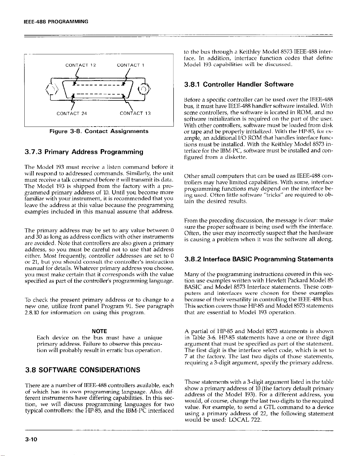
IEEE-488 PROGRAMMING
Figure 3-8. Contact Assignments
3.7.3 Primary Address Programming
The Model 193 must receive a listen command before it
will respond to addressed commands. Similarly, the unit
must receive a talk command before it will transmit its data.
The Model 193 is shipped from the factory with a pro-
grammed primary address of 10. Until you become more
familiar with your instrument, it is recommended that you
leave the address at this value because the programming
examples included in this manual assume that address.
The primary address may be set to any value between 0
and 30 as long as address conflicts with other instruments
are avoided. Note that controllers are also given a primary
address, so you must be careful not to use that address
either. Most frequently, controller addresses are set to 0
or 21, but you should consult the controller’s instruction
manual for details. Whatever primary address you choose,
you must make certain that it corresponds with the value
specified as part of the controllel’s programming language.
To check the present primary address or to change to a
new one, utilize front panel Program Yl. See paragraph
2.8.10 for information on using this program.
to the bus through a Keithley Model X573 IEEE-488 interface. In addition, interface function codes that define
Model 193 capabilities will be discussed.
3.8.1 Controller Handler Software
Before a specific controller can be used over the IEEE-488
bus, it must have IEEE-488 handler software installed. With
some controllers, the software is located in ROM, and no
software initialization is required on the part of the user.
With other controllers, software must be loaded from disk
or tape and be properly initialized. With the HP-85, for EX-
ample, an additional l/O ROM that handles interface functions must be installed. With the Keithley Model 8573 interface for the IBM-PC, software must bc installed and configured from a diskette.
Other small computers that can be used as IEEE-488 controllers may have limited capabilities. With some, interface
programming functions may depend on the interface being used. Often little software “tricks” are required to obtain the desired results.
From the preceding discussion, the message is clear: make
sure the proper software is being used with the interface.
Often, the user may incorrectly suspect that the hardware
is causing a problem when it was the software all along.
3.8.2 Interface BASIC Programming Statements
Many of the programming instructions covered in this sec-
tion use examples written with Hewlett Packard Model 85
BASIC and Model 8573 Interface statements. These com-
puters and interfaces were chosen for these examples
because of their versatility in controlling the IEEE-488 bus.
This section covers those HP-85 and Model 8573 statements
that are essential to Model lY3 operation.
NOTE
Each device on the bus must have a unique
primary address. Failure to observe this precaution will probably result in erratic bus operation.
3.8 SOFTWARE CONSIDERATIONS
There are a number of IEEE-488 controllers available, each
of which has its own programming language. Also, different instruments have differing capabilities. In this section, we will discuss programming languages for two
typical controllers: the HP-85, and the IBM-PC interfaced
3-10
A partial of HP-85 and Model 8573 statements is shown
in Table 3.6. HP-85 statements have a one or three digit
argument that must be specified as part of the statement.
The first digit is the interface select code, which is set to
7 at the factory. The last two digits of those statements,
requiring a 3.digit argument, specify the primary address.
Those statements with a 3.digit argument listed in the table
show a primary address of 10 (the factory default primary
address of the Model 193). For a different address, you
would, of course, change the last two digits to the required
value. For example, to send a GTL command to a device
using a primary address of 22, the following statement
would be used: LOCAL 722.
Page 62

IEEE-488 PROGRAMMING
Some of the statements have two forms; the exact configuration depends on the command to be sent over the
bus. For example, CLEAR 7 sends a DCL command, while
CLEAR 710 sends the SDC command to a device with a
primary address of 10.
The Model 8573 statements, which are also listed in Table
3.6, take on a somewhat different form. Each of these
statements uses the IBM BASIC CALL statement, with
various variables passed as shown in the table. The command words, such as IBCLR (Interface Bus Clear) and
IBSRE (Interface Bus Send Remote Enable), are, in fact,
BASIC variables themselves, which must be initialized at
the start of each BASIC program. In addition, you must
remember not to use these keywords for any other purpose in your BASIC program.
Before using the Model 8573 examples throughout this section, you must configure the software by using the procedure below. Note that the binary handier file called
GPIB.COM and the system configuration file called CONFIG.SYS must be present on the DOS boot disk, as described in the Model 8573 Instruction Manual.
1. Boot up your system in the usual manner and enter
BASICA.
2. Place the Model 8573 software disk into the default drive
and load the program called “DECL.BAS’: Modify the
program by changing the XXXXX values in lines 1 and
2 to 16000.
3. Add the following lines to the declaration file:
.;:s I,., $) 4;: :::r J I ,:;F:’ I :[;:c, ? !I : ,z: (A I_ I,,. 1,: :[I: 1: I I., 11,
8:: I.,, i:, :ib !, r: ,i I:, 0 ::.: ::I
c:’ ,.., ,:A :/,/: LX ? 1 I,[:: I..! (I, ? J
/.,I
8:: I., G $ u p, f, ‘Fi 3 :.; 1:s
‘;;I I..! ::.;; :::r ,, ,;., ,I: (4 i... ,.. ): :I;: F’ c, j:,
,:; 1, ., c, :i’ :.: , , -..’ ‘1,
_. .,,. *. II I .: .‘,,
: I::: 6, ,... 1. I :[;I F T ,..I I::,
4. Now save the modified declaraion file for future use.
Remember that you must load and run this short pxgram before using the Model 8573 programming examples throughout this section. Also, do nut use the
BASIC CLEAR or NEW commands after running this
program.
3.8.3 Interface Function Codes
The interface function codes, which arc pdrt of the
IEEE-488-1978 standards, define an instrument’s ability to
support various interface functions and should not bc cow
fused with programming commands found elsewhere in
this manual. The interface function codes for the Model
193 are listed in Table 3.7. These codes are also listed for
convenience on the rear panel adjacent to the IEEE-48X
connector. The codes define Model 193 capabilities ‘1s
follows:
SH (Source Handshake Function)-SH1 defines the ability of the Model 193 to initiate the transfer of message/data
over the data bus.
AH (Acceptor Handshake Function)-AI I1 defines the
ability of the Model 193 to guarantee proper reception of
message/data transmitted over the data bus.
T (Talker Function)-The ability of the Model 193 to send
data over the bus to other devices is provided by the 7
function. Model 193 talker capabilities exist only after the
instrument has been addressed to talk, or when it has been
placed in the talk-only mode.
I. (Listener Function)-The ability for the Model 193 to
receive device-dependent data over the bus from other
devices is provided by the L function. Listener capabilities
of the Model 193 exist only after the instrument has been
addressed to listen.
Table 3-6. BASIC Statements Necessary to Send Bus Commands
Action
Transmit string to device 10.
Obtain string from device 10.
Send GTL to device 10.
Send SDC to device 10.
Send DCL to all devices.
Send remote enable.
Cancel remote enable.
Serial poll device 10.
Send Local Lockout.
Send GET to device.
Send IFC.
i
3-11
Page 63
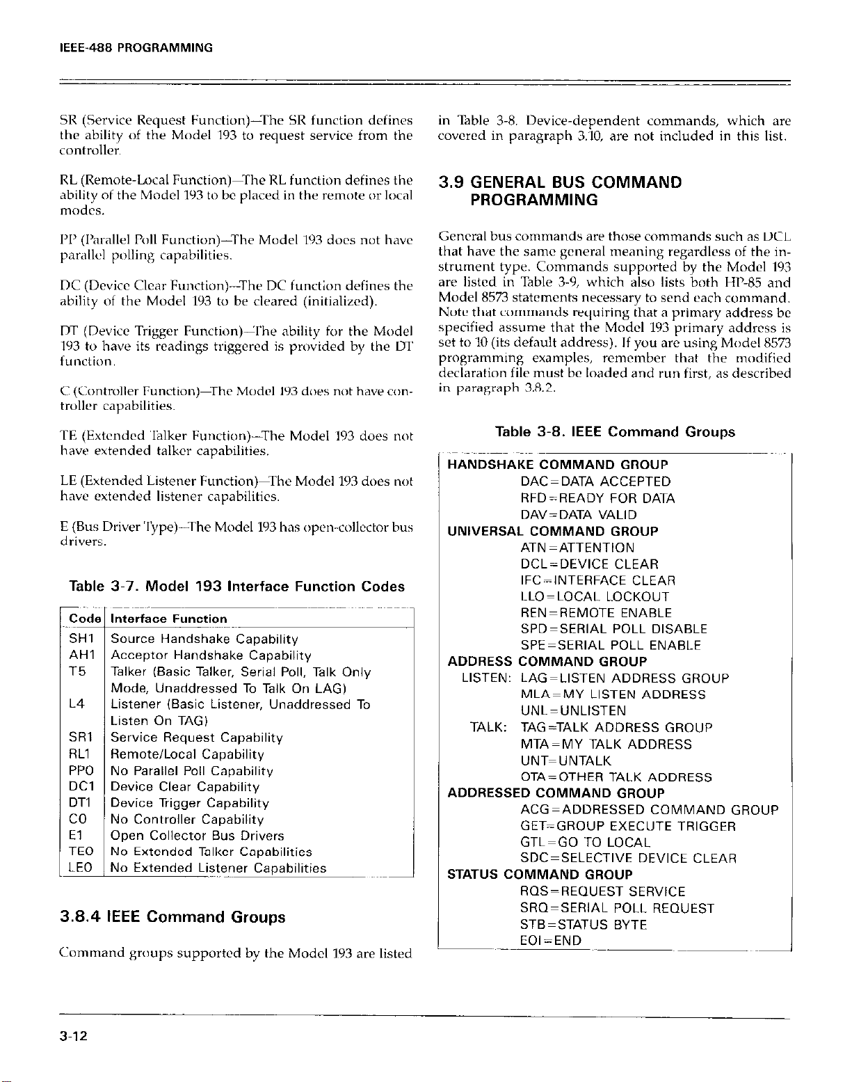
IEEE-488 PROGRAMMING
SR (Service Request Function)-The SR function defines
the ability of the Model ~193 to request service from the
controller.
RL (Remote-Local Fun&m-The RL function defines the
ability of the Model 193 to be placed in the remote or local
modes.
1’1’ (Parallel Poll Function)-The Model 193 does not have
parallel polling capabilities.
DC (Device Clear Function)-The DC function defines the
ability of the Model 193 to be cleared (initialized).
m (Device Trigger Function)Lrhe ability for the Model
193 to have its readings triggered is provided by the u1
function.
C (Controller Function)-rhe Model 193 does not have con-
troller capabilities.
TE (Extended ‘ljlker Function)-The Model 193 does not
have extended talker capabilities.
LE (Extended Listener Function)-The Model 193 does not
have extended listener capabilities.
E (Bus Driver Type)-The Model 193 has open-collector bus
drivers.
Table 3-7. Model 193 Interface Function Codes
Mode, Unaddressed To Talk On LAG)
Listener (Basic Listener, Unaddressed To
Listen On TAG)
No Controller Capability
Open Collector Bus Drivers
3.8.4 IEEE Command Groups
Command gmups supported by the Model 193 are listed
in Table 3-8. Device-dependent commands, which arc
covcrcd in paragraph 3.10, are not included in this list.
3.9 GENERAL BUS COMMAND
PROGRAMMING
General bus commands are those commands such as DCL
that have the same general meaning regardless of the instrument type. Commands supported by the Model 193
are listed in Table 3-9, which also lists both HI-85 and
Model 8573 statements necessary to send each command.
Note that commands requiring that a primary address be
specified assume that the Model 193 primary address is
set to 10 (its default address). If you are using Model 8573
programming examples, remember that the modified
declaration file must be loaded and run first, as described
in parajiraph 3.8.2.
Table 3-8. IEEE Command Groups
HANDSHAKE COMMAND GROUP
DAC=DATA ACCEPTED
RFD=READY FOR DATA
DAV=DATA VALID
UNIVERSAL COMMAND GROUP
ATN =ATTENTION
DCL=DEVICE CLEAR
IFC-INTERFACE CLEAR
LLO=LOCAL LOCKOUT
REN=REMOTE ENABLE
SPD=SERIAL POLL DISABLE
SPE=SERIAL POLL ENABLE
ADDRESS COMMAND GROUP
LISTEN: LAG=LISTEN ADDRESS GROUP
MLA=MY LISTEN ADDRESS
UNL=UNLISTEN
TALK: TAG=TALK ADDRESS GROUP
MTA=MY TALK ADDRESS
UNT=UNTALK
OTA=OTHER TALK ADDRESS
ADDRESSED COMMAND GROUP
ACG=ADDRESSED COMMAND GROUP
GET=GROUP EXECUTE TRIGGER
GTL=GO TO LOCAL
SDC=SELECTIVE DEVICE CLEAR
STATUS COMMAND GROUP
RQS=REQUEST SERVICE
SRQ=SERIAL POLL REQUEST
STB=STATUS BYTE
EOI=END
3-12
Page 64

IEEE-488 PROGRAMMING
Table 3-9. General Bus Commands and Associated BASIC Statements
T
t
Zomman
Id
REN
IFC
LLO
GTL
DCL
SDC
GET
:
3.9.1 REN (Remote Enable)
The remote enable command is sent to the Model 193 by
the controller to set up the instrument for remote operation. Generally, the instrument should be placed in the
remote mode before you attempt to program it over the
bus. Simply setting REN true will not actually place the
instrument in the remote mode. Instead the instrument
must be addressed after setting REN true before it will go
into remote.
To place the Model 193 in the remote mode, the controller
must perform the following sequence:
1. Set the REN line true.
2. Address the Model 193 to listen.
HP-85 Programming Example-This
automatically performed by the HP-85 when the following is typed into the keyboard.
F: ,::: 1, i::, “r E:: ;:’ :, l(jjl I:: E 1.4 I:1 L I I.1 E ::I
sequence is
Affect On Model 193
Goes into remote when next addressed.
Goes into talker and listener idle states.
Front panel controls locked out.
Cancel remote.
Returns to default conditions
Returns to default conditions.
Triggers reading in 72 an T3 modes
Cancel LLO
The instrument will go into the remote mode when the
return key is pressed the second time.
3.9.2 IFC (Interface Clear)
The IFC command is sent by the controller to place the
Model 193 in the local, talker and listener idle states. The
unit will respond to the IFC command by cancelling front
panel TALK or LISTEN lights, if the instrument \<ds
previously placed in one of those modes.
To send the IFC command, the controller need only set
the IFC line true for a minimum of 1OOr~scc.
HP-85 Programming Example-Before
IFC command, turn on the TALK indicator with the following statements:
demonstrating the
After the END LINE key is pressed, the Model 193 will
be in the remote mode, as indicated by the REMOTE light.
If not, check to see that the instrument is set to the proper primary address (lo), and check to see that the bus
connections are properly made.
Model 6573 Programming Example-To place the
193 into the remote mode, type the following lines into the
computer.
t.,.l ::.; ::: j. I::: i:, L, I,,, 1: 1; :;I. I;: E 8:: :[:: ,;: 1, Q 1.; !, I.,! y.;; ::, 8:: F: E “r ,._1 F: ,..I ::I
Model
At this point, the REMOTE and TALK lights should be on.
‘The IFC command can be sent by typing in the following
statement into the HI’-85:
H B 13 F: T I 0 7 I:: E H II L. I HE ::I
After the END LINE key is pressed, the REMOTE and
TALK lights will turn off, indicating that the instrument
has gone into the talker idle state.
Model 8573 Programming Example4’1xe
in the remote and talker active states with the following
statements:
the instrument
3-13
Page 65

IEEE-488 PROGRAMMING
After the return key is pressed the second time, the instrument should be in the remote and talker active states,
as indicated by the respective indicators.
To send IFC, enter the following statement into the
IBM-PC:
I:::: f:> I,,,, I,,,, :/I :I;:/ :y!!; :/I I:::: 8:: :I;: I::> ]::I !Llj/ Y:.;; ;r a:: /:;I: /jl:: “/ i(/ /:;I: I../ ::t
After the return key is pressed, the instrument will return
to the local and talker idle states.
3.9.3 LLO (Local Lockout)
The LLO command is used to remove the instrument from
the local operating mode. After the unit receives LLO, all
its front panel controls except POWER will be inoperative.
REN must be true for the instrument to respond to LLO.
REN must be set false to cancel 1.1.0.
3.9.4 GTL (Go To Local) and Local
‘The GTL command is used to take the instrument out of
the remote mode. With some instruments, GTL may also
cancel LLO. With the Model 193, however, REN must first
be placed false before 1.1.0 will be cancelled.
To send GTL, the cultroller must perform the following
SXp2”CC
1. Set ATN true.
2. Address the Model lY3 to listal.
3. Place the CTL command on the bus,
HP-85 Programming Example-Place the instrument in the
wmote mode with the following statement:
/:;I: I;;:: /I, /:::j “j /;I:: ‘;::I I/, ,;lj,
Now send GTL with the following statemc‘nt:
I ,... I:::/ 1:::: /:::I I~~.~ ‘I::’ :I~ /:I:/
/:; /I::: I.., :/I:, I,,, I[ I.,, /jj:: ::,
1:: /ii:: /..I :/::I I ..,. :/: I,./ 111: ::I
‘To send the LLO command, the controller must perform
the following steps:
1. Set ATN true.
2. Place the LLO command on the data bus
HP-85 Programming Example-The LLO command is sent
by using the following HP-85 statement:
/::I: E 1, i::, ‘i 1;;:: .;::I r:: [I I/ I::, [,,, 1: b., ti:: ::,
I,_ 1::) 1:::: $1 I ,,,. I ..,. I::1 1:: 1::: Cl I.! “r ‘;I:’ 4:: c:: !..I :[I I :I: II t;:: ::I
After the second statement is en&cd, the instrument’s
front panel controls will be locked out.
Model 8573 Programming Example-To send the LLO
command from the IBM-PC, type in the following
statements:
I.,! ::.;; :::: 1. : I:::: <, I.... I_
1:: PI II :$ :::: c: ,.., 1:;: :*:
After the return key is pressed, the Model 193 front panel
controls will be locked out.
1: :,jj 5; ,q; ,;i: I: :,i ,:+ I:, ,;:i :I.:: R I.,! :I.;; ::/ 1: ,::I: ,;;:: T ,,J ,:;I: I.., ::/
8:: :I;.: ,., :I. :I. j, I:::
I:: :I:: F: :o 1;lj19.;; !I 1:::: p, :I:, :/I/: ;I
6, I ,,,, ,,,, 1: :E: ,:I:: 111 1,
,; ,:I: E: “r ,,,I 6: I.., ::I
:$
When the END LINE key is pressed, the front panel
REMOTE indicator goes off, and the instrument goes into
the local mode. ‘lb cancel LLO, send the following:
I I:::/ 1:::: ,::,I ‘;I:’
Model 8573 Programming Example--Place the instrument
in the remote mode with the following statements:
I..! ::.;; ::z :I. /:::: ,::, /.... j,.., 1 :I;3 i;;;; 1;: 1;;:: I:: $;l I”: :I::, ,;lj, I!.;; !, I..! ::.;; ::,
I:::: 1/, :[, :ii:::::: :’ !’ I:.:; 1 !I : I:::: /:::, /,,,, /,,,, 1,: 1:: ,,.J /:;I:1
Now send GTL with the following statement:
1:::: ,:::, I.... /.... 1: :,‘: I I::, i::: I:: /II ,. ‘::;I :Ijl; ::.g ::/
After return is pressed, the REMOTE indicator turns off,
and the instrument goes into the local mode. To cancel
LLO, send the following:
I..! ::.;; :: ,;lj, $1: ,:::, I... ,... 1: :I;: i_; I-: ,i:: 4:: i‘, 11, ‘;;;I:$ ::.;; !, I.,! ::.;; 1:s
4:: 1::: II :/::I I ..,. :/: II i::: ::t
/:: ,:< ,:.: “I /.J 1:;: I,., ::a
/:: //, I/, ,;yg:iii; y.;; !/ ,111: /I/ :,:I/ :/,/: ::a
,:: 1;: Ij;:: -/ ,,J IpI: I.., ::,
I:: E: 1:: “r I..! PI: I../ ::I
8:: ,? I;;:: “/ I,,/ I:;$ I.., ::,
3.9.5 DCL (Device Clear)
The DCL command may be used to clear the Model 193
and return it to its power-up default conditions. Note that
the DCL command is not an addressed command, so all
3-14
Page 66

IEEE-488 PROGRAMMING
instruments equipped to implement DCL will do so
simultaneously. When the Model 193 receives a DCL command, it will return to either the factory default conditions
listed in Table 3.10 or to the user programmed default
conditions.
Table 3-10. Factory Default Conditions
Default
Mode
Function
Range
Data Format
Reading Mode
Self-test
EOI
Digital Filter
Exponential Filter Nl On
Zer0
Delay
SRQ
Rate
Trigger
Multiplex
Terminator
Data Store Rate
Data Store Sire
VallIe status
FO
R5
GO
BO A/D Converter
JO
KO Enable EOI and Bus
PO Disabled
zo
WOO.000 no delay
MO Disabled
s3
T6 Continuous on extw
Al Enabled
Z’
Qt5
IO Continuous
DC Volts
1ooov
Send prefix with data
Clear
Hold-off on X
Disabled
lOOmsec, 6%d
ml trigger
(CR)(LF)
One-shot mode
When the return key is pressed, the instrument returns
to the power-up default conditions.
3.9.6 SDC (Selective Device Clear)
The SDC command is a” addressed command that performs essentially the same function as the DCL command.
However, since each device must be individually addressed, the SDC command provides a method to clear
only a single, selected instrument instead of clexing ‘111
instruments simultaneously, ds is the c4se xvith DCI..
When the Model 193 receives the SDC‘ comrn.md. it will
return t” either the factory default unditions listed i” Gblc
3-10 or to the user progrdmnwd default conditions.
To transmit the SDC command, the contr~~ller n,ust prrfwm the following steps:
7. Set ATN true.
2. Address the Model lY3 to listen.
3. Place the SDC command on the dc&l bus.
HP-85 Programming Example-l’lxe
operating mode that is not d power-up dcfsult cunditiu”.
Now enter the following statenwnt into the HP-83
keyboard:
the unit i” 1~”
To send the DCL command, the controller must perform
the following steps:
1. Set ATN true.
2. Place the DCL command byte on the data bus.
HP-85 Programming Example--Place
operating mode that is not a power-up default condition.
Now enter the following statement into the fIl’-85
kevbaard:
I
When the END LINE key is pressed, the instrument
returns to the power-up default conditions.
/:::: I ,.,, 1;::: ,:::, ,:;: ‘i‘ 8:: 1;;:: ,.., :I::,
/ ..,, 1 I.., i;:: ::/
Model 8573 Programming Example-Place
operating mode that is not a power-up default condition.
Now enter the following statement into the IBM computer:
,111: p, :I::, :/I/: rz I:::: i..l R :/I/: 1:. ::.: I . . . . :I. /:I. 1:s ,y: (4 I... ,,_. :I: :/:I: i::: 111 I:1
,:: :I;:: 1;: I::, ,;lj, ::.; !, /:::: p, :I::, :/I/: ::/ i: 1:;: [I:: “r ,.,I F I~.., ::/
the unit in an
the unit in an
After END LINE is pressed, the instrument rrturns to the
power-up default co”dItl”“s.
Model 8573 Programming
operating mode that is not ‘, power-up default condition
Now enter the following statement into the IBM computer:
After the return key is pressed, the instrument returns tn
the power-up default conditions.
.,.
Example-Place the unit i” ‘m
,::::A ,,.,,. If:~;:[~.i:;: r::Pi 1. ‘X7.; ,:s g,, t?ETI~IF’tI
3.9.7 GET (Group Execute Trigger)
GET may bc used to trig:” the Model lY3 to take, I-wdingh
if the instrument is placed in the appropriate triM:” nwdt~
(more information on trigger nxldes nuy be found i”
paragraph 3.10.7).
To send GET, the controller lnust perform the folkwing
steps:
3-15
Page 67

IEEE-488 PROGRAMMING
1. Set ATN true.
2. Address the Model 193 to listen.
3. Place the GET command byte on the data bus,
HP-85 Programming Example-Type in the following
statements into the HP-85 keyboard to place the instrument
in remote and enable the correct trigger mode for this
demonstration:
,:;I: /;I:: //, I:::, “I E:: ‘;::’ 1,. i:, /:: 111: I.., ]::I ,,,,, :,: ,.., ,;y: ::I
,:::, ,,,I ~‘l’f:‘,,,/“r ‘;::’ j, ,;jj, ,; * !I “/ 1;;; ::.:; !I !S ,:; ,;;:: I.., :,I;/ I,,,, 1,: I.., fly: ::/
Now send the GET command with the following state-
ment:
“I If:’ :I: 1::;; 1:; 111:: /::I: ,:’ :I. llljl 1:: i::: I.,/:/::1 I.... :I I../ 1:::: ::I
When the END LINE key is pressed, the instrument will
process a single reading.
Model 8573 Programming Example-Type in the following statements to make sure the instrument is in the remote
and correct trigger modes for purposes of this
demonstration:
I,,) ::.; :::z :,. /:::: ,:::, /..., /.... :,: :,;;: :;I:; ,:;I: 1;;:: /:: :,I: ,:;I: :,::I ,;:j ::.;; !/ I.,/ ::.;; ::/ /:: ,:;1:,;;:: -I ,,J ,:;I: I.., ::/
/::::1/, :,:y,:/,/:::::: !I !I “[‘i;;::.:: !I I’ : ,:;I,::: ,/,,,,,,,,, 1,: :,$:,.J,:<“~ ,:: I// I/, i;;;,:;;;::.;; /, ,;:1’,,::,:$ ::,
I:: ,:‘: ii:: “i ,,,/ /:;I: I.., ::/
The serial polling sequence is conducted as follows:
‘I. The controller sets ATN true.
2. The controller then places the SPE (Serial Poll Enable)
command byte on the data bus. At this point, all active
devices are in the serial poll mode and waiting to be
addressed.
3. The Model .I93 is then addressed to talk.
4. The controller sets ATN f&c.
5. The instrument then places its status byte on the data
bus, at which point it is mad by the controller.
6. The controller then sets ATN true and places the SPD
(Serial Poll Disable) command byte on the data bus to
end the serial polling sequence.
Once instruments are in the serial poll mode, steps 3
through 5 above can be repeated by sending the correct
talk address for each instrument. ATN must be true when
the address is transmitted and false when the status byte
is read.
HP-65 Programming Example-The HP85 SI’0I.L state-
ment automatically performs the sequence just described.
To demonstrate serial polling, type in the following
statements into the HI’Vi5:
/:;I: /;;:: 111 /:::I “/ 1;;:: .;::I :/, i;ljt 8:: 1;;;. I../ :,::I I,,,, :/I b..j 1;:: ::t
~~~~;::::::~~~;,:::‘,:::,~,,,/,,,, /:: ‘;::I ,, i;;, ::/ /:: ,;;:: I..,:[:, I,,,, 1,: / ..// I;;, ::/
:I::$ Ii: :!I;; I:::’ :!!!; 8:: /II:: I../ ]::I I,,,, :[ I.., El:: I:/
Now send GET to the instrument with the following
statement:
/:::: ,:::/ I,,,, /,,,, 1,: :,;;t “/ ,:;I: I::;; /:: p, 1,. ‘;;;I :Ij;; :I.;; ;, 8:: /:;I: [I:: “I I,,/ /:;I: I.., ::/
When the return key is pressed, the instrument will process a single reading.
3.9.8 Serial Polling (SPESPD)
The serial polling sequence is used to obtain the Model
193 status byte. The status byte contains important information about internal functions, as described in paragraph
3.10.13. Generally, the serial polling scquencc is used by
the controller to determine which of several instruments
has requested service with the SRQ line. However, the
serial polling sequence may be performed at any time to polling sequence is conducted. ‘I’he status byte value is
obtain the status byte from the Model 193. *,sprayeci when the return key IS pressed the ttw-* t,mc!.
..~
When the END LINE key is pressed the second time, the
computer conducts the serial polling sequence. The
decimal value of the status byte is then displayed on the
computer CRT when the END LINE key is prcsscd the
third time. More information on the status byte may be
found in paragraph 3.10.13.
Model 8573 Programming Example-Use the following sequence to serial poll the instrument and display the
decimal value of the status byte on the computer CRT:
I,,) ::.;;:z: 1,. ,I:: ,:q /,,,, /,,_ I[ 1,;:: :;;j; /:;: ,jj:: /:: I[:: ,i 10 ,;j ::.;; !/ I,,/ ::.;; ::/ 8:: ,:;I: ,;yy,“[ /,,I ,:zp.,, 1:s
i:: I;I I,,,, /,, :/: :E; /:;I: :i’; I:::’ 8:: p, :,, ‘:;I :I:; ::.;; T :I; :,;: ::.; ::/ 8:: ,:;I: t;:: “/ /,,I ,:;I: f.., ;,
[::, I:;: :/I I../ “/ ;I;;; :I;;; y:.;; ,:: /:;I: /;;;; “/ j,,/ f;;: i.4 11,
When the return key is pressed the second time, the serial
..~
3-16
Page 68

IEEE.488 PROGRAMMING
3.10 DEVICE-DEPENDENT COMMAND
PROGRAMMING
IEEE-488 device-dependent commands are used with the
Model 193 to control various operating modes such as
function, range, trigger mode and data format. Each com-
mand is made up of a single ASCII letter followed by a
number representing an option of that command. For example, a command to control the measuring function is
programmed by sending an ASCII “F” followed by a
number representing the function option. The IEEE-488
bus actually treats these commands as data in that ATN
is false when the commands are transmitted.
A number of commands may bc grouped together in one
string. A command string is usually terminated with an
ASCII “X” character, which tells the instrument to execute
the command string. Commands sent without the execute
character will not be executed at that time, but they will
be retained within an internal command buffer for execution at the time the X character is received. If any errors
occur, the instrument will displa a propriate front panel
error messages and generate an
so.
C! R 6 if programmed to do
If an illegal command (IDDC), illegal command option
(IDDCO), is sent, or if a command string is sent with REN
false, the string will be ignored.
Device-dependent commands that control the Model IY3
are listed in Table 3.11. These commands arc cwercd in
detail in the following paragraphs. The associ.ltcd pn’gramming examples show how to send the wmmands
with both the HI’-85 and the IBM-I’CII(S73
NOTE
Programming examples assume’ that the Model
193 is at its factory default value of IO.
In order to send a device-de endent command, the cow
troller must perform the Y fol owmg steps:
I. Set ATN true.
2. Address the Model lY3 to listen.
3. Set ATN false.
4. Send the command string over the bus one byte at a
time.
Commands that affect instrument operation will trigger a
reading when the command is executed. These bus commands affect the Model 1Y3 much like the front panel controls. Note that commands are not necessarily executed in
the order received; instead, they will be executed in
alphabetical order. Thus to force a particular command sequence, you would follow each command with the execute
character(X), as in the example strin , LUXF2X, which will
reset the instrument to factory defau
select the ohms function.
Device-dependent commands can be sent either one at a
time, or in groups of several commands within a single
string. Some examples of valid command strings include:
FOX-Single command string.
FOKlPOROX-Multiple command string
T6 X-Spaces are ignored.
Typical invalid command strings include:
ElX--invalid command, as E is not one of the instrument
commands.
FlSX-Invalid command option because 15 is not an option
of the F command.
f ”
t condltlons and then
NOTE
REN must be true when sending device
dependent commands to the instrument, or it
will ignore the command and display d bus error message.
General HP-85 Programming Example-Devicr-depell~i~tlt
commands may be sent from the HI’-85 with the tallowmg statement:
A$ in this case contains the ASCII characters reprcscnting
the command string.
General Model 8573 Programming Example-Use the
following general syntax to send device-dependent c<,nlmands from the IBM-PC:
Again, CMD$ contains the command letters to program
the instrument. Rememhcr that the modified declaration
file must he loaded and run before using any of the pn>gramming examples.
3.17
Page 69

IEEE-488 PROGRAMMING
-
Vlode
Execute
%nction
hnge
Trigger Mode
Reading Mode
Table 3-11
-
Command
X
FO ~~
Fl
F2
F3
F4
F5
F6
F7
F8
F9
FIO
Fll
F12
F13
I30
RI
Fiz
R3
R4
Fi5
R6
R7
R8
20
21
22
PO
P”
so
Sl
s2
s3
TO
Tl
T2
T3
T4
T5
T6
T7
60
El
Device-Dependent Command Summary
I.
Description
Execute other device-dependent commands.
DC Volts
AC Volts
3hms
DC Current
AC Current
Temperature in “F mode
Temperature in OC mode
ACV + DC
ACA + DC
Low Frequency ACV + DC
ACV dB
ACA dB
ACV + DC dB
ACA + DC dB
DCV
Auto Auto
200mV 2V
2v 2ov
2ov 2oov
2oov 7oov
looov 7oov
1ooov
looov 7oov
1ooov
Zero disabled
Zero enabled
Zero enabled using a zero value (VI
Filter disabled
Filter on with a value of n (n=l to 99)
318~sec integration at 3%d resolution
2.59msec integration at 4%d resolution
Line cycle integration at 5%d resolution
Line cycle integration at 6%d resolution
Continuous on Talk
One-shot on Talk
Continuous on GET
One-shot on GET
Continuous on X
One-shot on X
Continuous on External Trigger
One-shot on External Trigger
Readings from A/D converter
Readings from data store
-~
,~~
ACV DCA
Auto Auto
200fiA 200pA 2000
2mA 2mA
20mA 20mA 20kQ
200mA 200mA 200kR
2A 2A
7oov 2A
2A 2A
7oov 2A
ACA Ohms
2A 20MR
2A 200MQ Type 6
Temp
AlltO Pt. 385
Pt. 392
2kR
2MR
200MR Type S
.~-
TYPO K
TVP~
J
TYPO T
TVP~ E
TVP~ R
Paragraph
3.10.1
3.10.2
3.10.3
3.10.4
3.10.5
3.10.6
3.10.7
3.10.8
I
3.18
-
Page 70

Table 3-11. Device-Dependent Command Summary ICont.1
IEEE-488 PROGRAMMING
Mode
Data Store Size
Data Store Interval
Value
Calibration
Default Conditions
Data Format
sm
EOI and Bus Hold-ofi
Terminator
status
Command
IO
I”
QO
an
v*nn.nnnn or
V+n.nnnnnnE+r
co
Cl
LO
Ll
GO
Gl
::
G4
G5
MO
Ml
M2
M4
M8
Ml6
M32
KO
Kl
K2
K3
YmX
YmnX
YX
uo
Ul
u2
u3
u4
u5
U6
u7
Description
Continuous data store mode
Data store size of n (n=l to 500)
cne-shot into buffer
n=interval in milliseconds (lmsec to 999999msecl
Calibration value, zero value and reference junction
temperature value.
Calibrate first point using value IV)
Calibrate second point using value (VI
Restore factory default conditions.
Store present machine states as default conditions.
Reading with prefixes.
Reading without prefixes.
Buffer readings with prefixes and buffer locations.
Buffer readings without prefixes and with buffer
locations.
Buffer readings with prefix and without buffer
locations.
Buffer readings without prefixes and without buffel
locations.
Disable
Reading Overflow
Data Store Full
Data Store half full
Reading Done
Ready
Error
Enable EOI and bus hold-off on X.
Disable EOI, enable bus hold-off on X.
Enable EOI, disable bus hold-off on X.
Disable both EOI and bus hold-off on X.
One terminator character
Two terminator characters
No terminator
Send machine status word.
Send error conditions.
Send translator words.
Send buffer size.
Send average reading in buffer.
Sand lowest reading in buffer.
Send highest reading in buffer.
Send current value.
Paragraph _
3.10.9
3.10.9
3.10.10
3.10.10
3.10.11
3.10.12 ’
3.10.13
3.10.14
3.10.15
3.10.16
1
3-19
Page 71

IEEE-488 PROGRAMMING
Table 3-11. Device-Dependent Command Summary (Cont.)
,:--~x~+;~”
l”l”“G
Multiplex
Delay
Self-test
Hit Button
Display
1
““llllllOllY Y”S”‘.),..Y..
A0
Al
Wn
JO
Hn
Da
Multiplexer disabled
_Multiplexer enabled
n=delay period l.OOOsec to 60sec.)
Test ROM, RAM, NVRAM.
Hit front panel button number n. k&e Figure 3-13).
Display up to 14 character message. a-character.
D Cancel display mode.
Reference Junction 00
01
Exponential Filter
NO
Nl
Measure reference junction.
Here is reference junction temperature using value.
Internal exponential filter off.
Internal exponential filter on.
3.10.1 Execute 1x1
The execute command is implemented by sending an
ASCII “X” over the bus. Its purpose is to direct the Model
193 to execute other device-dependent commands such as
F (function) or R (range). Usually, the execute character
is the last byte in the command string (a number of commands may be grouped together into one string); however,
there may be certain circumstances where it is desirable
to send a command string at one time, and then send the
execute character later on. Command strings sent without
the execute character will be skx-ed within an internal command buffer for later execution. When the X character is
finally transmitted, the stored commands will be executed,
assuming that all commands in the previous string were
valid.
.” .I=,- r..
3.10.17
-
3.10.18
3.10.19
3.10.20 ~’
3.10.21
3.10.22
3.10.23
When the return key is pressed the second time, the X
character is transmitted to the instrument, although no
mode changes occur because no other commands aw
transmitted. Note that the instrument remains in the
listener idle state after the command is transmitted because
IBWRT automatically sends UNT (Untalk) and UNL
(Unlisten) at the end of the transmission sequence.
3.10.2 Function (F)
The function command allows the user to select the type
of measurement made by the Model 193. When the instrument responds to a function command, it will be ready
to take a reading once the front end is set up. The function may be programmed by sending one of the following
commands:
HP-85 Programming Example-Enter the following
statements into the HP-85 keyboard:
,:;: E: p,,:::, ‘i” ,111: ;::’ 1, ,;jj, /:: E I../ 113 I :I: /j., 1;;:: ::I
/;:I, ,.,) “I I:::, /,,I “r ‘;::’ 11, ,;lj, ,; ? I’ I:.:: !V I’ ,:: 1;;:: I.., I::, I ,,,, :,: ,.., 1;;: ::,
When the END LINE key is pressed the second time, the
X character will be transmitted to the instrument. No mode
changes will occur with this example because no other
commands were sent. Note that the instrument remains
in the listener active state after the command is
transmitted.
Model 8573 Programming Example-Enter the following
statements into the IBM computer:
I,,) ::.;; ::: 1,. I:::: (3 ,,_ I,,,, 1: 1;; :ii: ,:< [; I:: 1;; ,:, :,::, r:j ;.;; y l,.j ::.;; ::/ t:: I:;> i;:: ‘y ,..I FI: I../ ::!
1:; p/ j::,:$::::: !I n ::.:: !I !’ : ,:::,:::, I ,,,, /,,,, 1: 1,;: l..j/:;;“~ ( p, 1,. “;I:!; ::.;; A ,z: 1, 1, :ik 1:s
I: I:;’ ,:j:: “/ I.,) f;l: I., ::a
3-20
FO = DC Volts
Fl = AC Volts
F2 = Ohms
F3 = DC Current
F4 = AC Current
F5 = Temp in +F mode
F6 = ‘Temp in +C mode
F7 = ACV + DC
F8 = ACA + DC
F9 = Low Frequency ACV + DC
FlO = ACV dB
Fll = ACA dB
F12 = ACV + DC dB
Fl.? = ACA + DC dB
Page 72

IEEE-488 PROGRAMMING
Upon power-up, or after the instrument receives a DCL
or SDC command, the Model 193 will return to the default
condition.
HP-85 Programming Example-Place the instrument in the
ohms function by pressing the OHMS button and enter
the following statements into the HP-85 keyboard:
g;: 11: 1110 ‘r [i:: 7:’ 1 lljjl I:: E:: II :I::1 1.. 1: I..[ E:: ::I
g,/,-rf:‘,“j’i .;::3 1, (j ,; 1 ? I::“g,;:.:; 1 1 (1 ,;:!..,I, L I bjiy: ::,
When END LINE is pressed the second time, the instru-
ment changes to the DC volts mode.
Model 8573 Programming Example--Place the instrument
in the ohms function by pressing the OHMS button and
enter the following statements into the computer keyboard:
I..) I,; = 1. : I::: A I_ L.. I E :.: F: F_ I:: B R I:I ~3 I$ > l.,J :.: ::I
(1: p, 1, :+ :z 1 ? F ,@ ).:: 1 9 : 1.: A ,,. L I R ,.J F: T (1 p, 1 ‘;I 3 :.: y ,I: p, 1, g :,
a:: R E T’ 1-I I;: t.4 ;I
When the return key is pressed the second time, the instrument changes to the DC volts function.
( [? E T IJ R t.1 1:s
3.10.3 Range (RI
respective ranges for each measuring function are sun,marized in Table 3-12. The instrument will bc ready to take
a reading after the range is set up when responding to ‘1
range command.
Upon power-up, or after the instrument receives a DCI.
or SDC command, the Model lY3 will return to the default
condition.
HP-65 Programming Example-Make sure the instrument
is in the autorange mode and then enter the following
statements into the HP-85:
I;: E b1111 T EI I’ 1 1-11 g:: E H II L I HE ::I
Ol,.!TPl.! T ; 1 ii .; > ) h:s;:.:: ! y f:: E HD L I t.,E ::I
When the END LINE key is pressed the second time, the
instrument cancels the autorange mode, and enters the 1C3
range instead.
Model 8573 Programming Example-Make sure the instrw
ment is in the autorange mode. Now enter the following
statements into the IBM-PC keyboard:
I..! ‘: = 1, I:: &L,L L I B!:; F:E ( E:F: 110 Z.: T I.,!;.; 1:s s:: F: E T IJF: t.1 ::I
,:p,I,$:=” ? F’:::.::” ? ifiLL. IE:,.,F:TI::~,1’j3~.:t ,;:p,1,*::,
I:: RET I.1 F: t.1 ::I
The range command gives the user control over the sen-
sitivity of the instrument. This command, and its options,
perform essentially the same functions as the front panel
range buttons. Range command parameters and the
Table 3-12. Range Command Summary
Command DCV
RO
Rl 200mV 2V 200 fiA 200 PA 200 R
R2 2 v 2ov
R3 20 v 2oov
R4 200 V 700V 200mA 200mA 200 kR
R5 1000 V 700V 2 A 2 A 2MR
R6 1000 V 700V 2 A 2 A 20MR
R7 1000 V 700V 2 A 2 A 200MR
R8 1000 V 700V 2 A 2
Auto
ACV DCA ACA OHMS
Auto Auto
When the return key is pressed the second time, the instrument cancels the autorange mode and switches to the
R3 range.
Range
1
TEMP
Auto
2mA 2mA
20mA 20mA 20 kR
Auto
2 k0
A 200MR
pt. 365
Pt. 392
TVP~ ii
TVP~
TVP~ T
TVP~ E
TVP~ R
TVP~ S
Tvae 6
J
3-21
Page 73

IEEE-488 PROGRAMMING
3.10.4 Zero (2)
Over the bus, the zero modifier can be controlled in the
same way that it is controlled from the front panel. Refel
to paragraphs 2.62 and 2.8.5 (zero program) for a complete
description of the zero modifier. The zcm modifier is controlled by sending one of the following LC~ commands
CI”Cl- the bus:
%O r Zen, disabled.
Z1 = Zero enahlcd.
Sending Ill has the same affect as pressing the ZERO but-
ton. Zero will enable, and the display will zero with the
input signal hccoming the zero baseline level. The baseline
will br stored in Program ZERO.
‘l’hc L2 command is used when a zero value, using the
V command, has already been established. When the 22
command is sent, subsequent readings reprcscnt the dif-
ferrncc between the input signal and the value of V. Also,
the value of V is stored in Program ZERO. For example,
with 0.5V on the input, sending the command strings VZX
Z2X will result with Zero being enabled and the instrw
ment reading ~-l.SV (0.5 -2.0 = -1.5).
I.,! ::.;; ::::: ~1, 1:;;: ,:::, / ,,,, I,,,, :I: E 1;;;; I:;> i::: ::I :I;;: 1:;; :/::I /;jl :I.;; !, I.,/ I.;; ::, ::: /:;I: 1;::: “/ i,,,i /:;I: /~~~j ::r
,:I:: p/ :,I:/ :/,/: ::::: !I I’ I.,! :/, I:.:: :! 1 /:::: <:, I,,,, /,,,, 1,: 1,;;: /../ ,:;l; “/ t:: /jj :/, ‘;;I/ 7;; ::.;; // ,:::: /(/ :/::I :ii: ::a
!:: /:;I: ,:;:: “! /~,/ /:;I: I.., ::/
When the return key is pressed the third time, the ZERO
indicator will turn on with a zero baseline lcvcl of ‘lVD<:.
Thr ax1 value will also bc stored in the LCTO program
3.10.5 Filter (P)
The filter command controls the amount of fillwing applied to the input signal. The Model 193 filters the signal
by taking the weighted average of a number of succcssivc
reading samples. Since noise is mostly random in nature.
it can be largely cancelled out with this method. ‘l‘he
number of readings averaged (filter value) can be from I
to 99, The filter value can bc programmed by sending one
of the following commands:
PO = Filter disabled
Pn = Filter (I” with a value of n. Where n can be from
1 to 99.
Sending the %2 command without a V value established
is the same as sending the Zl command. See paragraph
3.10.~10 for more information on using the V command.
Upon power-up or after the instrument receives a DCL or
SK command, the Model 193 will return to the default
condition. The value of V will reset to zero.
HP-85 Programming Example-Set the instrument to the
2VDC range. With the front panel ZERO button, disable
the zero mode, if enabled, and enter the following
statements into the 1IP-85 keyboard:
After the END LINE key is pressed the third time, the
ZERO indicator will turn on with a zero baseline level of
1VDC. The zero value will also be stored in Program ZERO.
Model 8573 Programming Example-Set the instrument
to the 2VDC range. With the front panel ZERO button,
disable the zero mode, if enabled, and enter the following statements into the computer keyboard:
Upon pawr~up or after the instrument wxivcs a DCI. (11
SDC command, the Model ‘I93 will return to the default
condition.
Notes:
1. A filter value sent owx the bus is stored in Program
FILTER, replacing the previous filter value.
2. Keep in mind that each function can have its own
unique filter value.
HP-85 Programming Example-With the front panel
FlI.TER indicator off, enter the following statements into
the HP-85:
,q,ii:: p, ,y;, “I j;;:: ‘;::I 1,. ,::, ,:: /;;:: I.., I::, /,,,, 1,: I.., El:: ::/
,:::, /,j “I 1::’ I,,/ “r ‘;::I 1 ,;jj, ,; R !I ,:::, 2;; ,;;;/ i:.:; ? IS ,:: ,111: // :,I:/ I,,,, 1: I.,, /jj:: ::/
When the END LINE key is pressed the second time, the
filter will turn on and have a filter value of 20.
Model 8573 Programming Example-With the front panel
FILTER indicator off, enter the following statements into
the computer:
I..! ::.;; :z :/. 1:: I? ,... ,.
,T 1‘1 I:, :iF 1::: ! I’ I:::‘;;; ,;lj, ::.:I ? i
1 :I:; !‘I; R [. 4:: :E: ,‘D ,;3 ::.;; !/ I.,! ::;; ::I
i: Q ,,,, ,- 1,: 1;; 1.1 F; “I /:: p, 1, c;, 7; ::.; !, ,111: p, :,:I, :/,/: ;,
4:: k: ,;y: “I ,,,j ,:;: b., ::r
,:: ,‘f;:: “/ ,..j/;: I.., ::,
3-22
Page 74

IEEE-488 PROGRAMMING
When the return key is pressed the second time, the filter
will enable and have a filter value of 20.
3.10.6 Rate (S)
The rate command controls the integration period and the
usable resolution of the Model 193. The rate commands
are as follows:
SO = 318~111s~ integration at 3%d resolution
S1 = 2.59msec integration at 4%d resolution
52 = Line cycle integration* at 5%d resolution
53 = Line cycle integration* at 6%d resolution
* 20msec for 50Hz and 16.6msec for 601 lz
Upon power-up or after the instrument receives a DCL or
SDC command, the Model 193 will return to the default
condition.
HP-85 Programming Example-Using the front panel
RESOLN button, set the display of the Model 193 for 6%d
resolution. Now enter the following statements into the
HP-85:
,:;: ,j::: p, ,y;, “r ,;::: ‘;::I :,, ,;lj, ,:: ,;I I.., I:, I,,,, 1,: I.., i: ::I
,y:, ,,,j “I j:::, /,,) “I ‘;::I j, ,;jj, ,; ? !b :I:;; :,, I:.:: !I ? ,:: 1;;:: i.., :I::, /,,,, 11: b,, ,111 ::,
TU = Continuous On ‘Talk
Tl = One-shot On Talk
T2 = Continuous On GET
T.? = One-shot On GE?
T4 = Continuous On X
T5 = One-shot on X
T6 = Continuous On External Triggel
T7 = One-shot On External Trigger
The trigger modes are paired according to the type of
stimulus that is used to trigger the instrument. In the ‘IU
and ‘I? modes, triggering is performed by addressing the
Model 193 to talk. In the 1‘2 and 13 modes, the IEEE-488
multilinc GET command performs the trigs:” tunrti<)n
The instrument cxecutc (X) character provides the tr&c,r
stimulus in the T4 and T5 modes. l%tern.~l triggrr pulws
provide the trigger stimulus in the Th ,md T7 modes.
Upon power-up or after the instrument receives il IICI. i)r
SDC command, the Model ~193 will return t,, the default
condition.
When END LINE is pressed the second time, the 51 rate
will be selected.
Model 8573 Programming Example-Using the front panel
RESOLN button, set the display of the Model 193 to 5%d
resolution and enter the following statements into the
computer:
I.,! ::.;; I::: 1,. I:::: (; I ,,,, ,,,, :,: :[I: 1;;;: /:I: ,:: /:: x; ,:q I::, ,;j ::.;; I I/ ::.;; ::, 8:: ,:;I: [::: “L /,_I 1:;: f..l ::/
,111: //1:1::, :/I/: I::: !’ I’ ::; 1,. ::.:: !’ !/ ,111: ,q /,,,, I,., 1 :1jj: ,.j r+1” ,:: 1’1 1, y:; ::.;; *
3:: ,::I: /I;:: -[ 1.J f;: I.., ::I
When the return key is pressed the second time, the SI
rate will be selected.
,I:: p, I::, j:: ::a
3.10.7 Trigger Mode (T)
Triggering provides a stimulus to begin a reading conversion within the instrument. Triggering may be done in two
basic ways: in a continuous mode, a single trigger con-
mand is used to start a continuous series of readings; in
a one-shot trigger mode, a separate trigger stimulus is rcquired to start each conversion. The Model 193 has eight
trigger commands as follows:
Model 8573 Programming Example-Place the instrument
in the Tl mode with the following statenwnts:
!,.I :I.:: ::::: :,, : /:::: i::, I.... ,,,, 1,: 1,;: ii; it; E: 8:: 1;: i;: I:, @ ye; y /,/I.; ::/
I, ,:;: E: ‘1~ / / F’ , 1
3-23
Page 75

IEEE-488 PROGRAMMING
Each time the IBRD function is called, the instrument is
addressed to talk, at which time it is triggered. When the
conversion is complete, the reading is sent out over the
bus to the computer, which then displays the resulting
data.
3.10.8 Reading Mode (B)
The reading mode command parameters allow the selection of the source of data that is transmitted over the
IEEE-488 bus. Through this command, the user has a
choice of data from the AID converter (normal DMM
readings) or the buffer (data store). The reading mode com-
mands are as follows:
BO = A/D Converter readings
Bl = Data Store readings
Upon power-up or after the instrument receives a DCL or
SDC command, the Model 193 will return to the default
condition.
When in BO, normal AID readings will be sent. In a continuous trigger mode, readings will be updated at the conversion rate. The Bl command is used to access readings
from the buffer. When the 81 command is sent, subsequent readings will be taken from consecutive buffer locations beginning with the first memory location (001). Once
all readings have been requested, the unit will cycle back
and begin again.
HP-85 Programming Example-Prom the front panel, store
some readings in the data store. Enter the following
statements into the computer to read the stored reading
in the first memory location of the buffer. The reading will
be displayed on the computer CRT.
1;: ,111 p, /:::, ‘,- ,;;:: .;::I :i ,;lj, ,:: i;:: I.., :,::, /,., 1,: I.., ,;;:: ::/
,:::/,,, j”j,:::/,,,j./ ‘,i 1,. Q ,; !I R :,I: :,, ::.:: Y !I 8:. ,~~::~..,]::, /,, :[ I..,, ;I:: >I
,:: I.,, -/ ,;;I ,:;I: ‘;‘ 1 ,;jj, .; jl:, 5,; ,:: ,;;:: I.., 111, I-,, i I.., f;:: ::/
i:, :[ :;jj; /:::I g:, :i,; /:: [;:: I.,, :,::I / ,,,, 1: I.., El: ::/
The second statement above sets the instrument to the buffer reading mode. The third and fourth statements acquire
the reading and display it on the CRT.
Model 8573 Programming Example-From the front panel,
store some readings in the data store. Enter the following
statements into the computer to read the stored reading
in the first memory location of the buffer. The reading will
be displayed on the computer CRT.
/.,I y:.;;::::: :,, ,111: (j I,,,, ,,,, :,: :E: :;;;; /:;I: ,I_ 8:: :[i: [:‘:,::, c, ::.; !, I.,/ ::.;; 1:s 8:: ,:I: /jj::..r /,,j ,:;:f.., ;,
,:::: /I, 1:) :/,/: ::::: ? !I 1;;: 1,. I:.:: 1 * ,111: G I,,,, i, 1 1,:: ,,.I /:;I: “I ,:: 1, 1,~ .:I, 15 y:.;; !/ c:: p, 11, :f: ::/
i: ,:<,i;:: -[ ,.j ,:;I: t.., ::/
,:;I/ ], :::::
2,:: :f; /:::. ,:::,
,z ,;;:: :/,/: ,:: :;;;: jjjj; ::, ,:: ,::: ,,,,, I,-, 1,: :,ii; I; :,I;, (1 1, :,, ‘;;I :3 :I.;; p ,:: :,::I >t: ::I
:
I:: i;: E: ~‘/_ I.,) i;: [..I ::I
I:::( ,;’ ‘,I I.., “/ ,:;I: :,:I, :,;: /:: ,:;I: E: “[ ,,,j ,:< I.~, ::,
The second statement above programs the reading mode
to access the buffer reading. The third statement addrcsscs
the instrument to talk and reads the data string from the
instrument, while the fourth statement prints the data
string on the computer CRT.
3.10.9 Data Store Interval (0) and Size (II
The data store is controlled by the interval command (Q)
and the size command (I). It is important to be aware at
this time that either command will start the storage pro-
cess. Thus, if both the interval and the size are to be
modified, they must be sent together in the same command string.
With the Q command, the user can select the interval that
the instrument will store readings or select the one-shot
mode. In the one-shot mode, one reading will be stored
each time the instrument is triggered. The Q command
is in the following form:
QO=One-shot into buffer
Qn=Sct storage interval in millisec (lmsec to YYYY99msec)
To use the data store in the one-shot mode (QO), the in-
strument must be in a one-shot trigger mode (TI, l3, T5
or T7). In the QUIl mode, one reading will be stored each
time the instrument is addressed to talk. In the Qo7J
mode, each GET command will cause one reading to be
stored. In the Qm5 mode, each instrument execute
character (X) will cause’ a reading to bc stored. Finally, in
the QOr7 mode, each external trigger pulse will cause a
reading to be stored. If the instrument is in a continuous
trigger mode (TO, T2, T4 or T6), an IDDC error will occur.
To store readings at a selected interval (Qn), the instrument can be in any trigger mode. When the selected trigger occurs, the storage process will commence.
The size of the data store can be controlled by one of the
following I commands.
IO=Continuous storage mode.
In=% data store size to n (1 to 500).
3-24
Page 76

IEEE-488 PROGRAMMING
In the continuous data torage mode (IO), storage will not
stop after the buffer is filled (500 readings), but will proceed back to the first memory location and start overwriting data. With the Innn command, the storage process will stop when the defined number of readings have
been stored. In this case the buffer is considered to be full.
Notes:
1. The storage process will start when either the Q or I
command is sent over the bus.
2. The data store is disable by sending an F command that
places the instrument in a different function.
3. The instrument must be in a valid operating state in
order to use the high speed data store capabilities. The
high speed intervals are lms, Zms, 3ms and 4ms. Valid
commands are listed in Table 3.13.
4. With 52 or 53 asserted, the fastest valid storage interval (I) is 40msec. An interval less than 40msec will result
in a short period error when the storage process is
started. Readings will be stored as fast as the instrument
can run.
5. Either during or after the storage process, readings may
be recalled by using the 81 command as described in
the last paragraph. Also, the highest, lowest and average
reading is a full buffer can be recalled by suing the appropriate U commands. See paragraph 3.10.18 for information on using the U commands.
Upon power-up or after the instrument receives a DCL or
SK command, the Model 193 will return to the default
condition.
PROGRAM
Set read mode to
data store.
I*mp 100 times.
Grt a reading.
Display it.
Ixwp back and get
next reading
After entering the program, press the FIP-85 RUN key. ‘The
program will set the store siz.e to 100 (line 30), enable the
data store (line 30), wait for memory to fill (lines 40 ,md
SO), turn on the data store output (line 60). and then request and display all 100 readings (lines 70.100).
Model 8573 Programming Example-To demonstrate data
store operation, load the modified DECL.BAS file and
enter the program linrs below:
HP-85 Programming Example-Enter the program below
to enable data store operation and obtain and display 100
readings on the computer CRT:
Table 3-13. High Speed Data Store
Valid Data
Data Store Interval
61 II-1500 F4:F;F8 RO
I
*Data store sire IO (continuous) cannot be used in the high speed data store mode.
Store Size*
I I
Valid Functions
FO Fl F3
Valid Ranges
-~
All, except
I
Valid Reading Rates
so
so, 51
3-25
Page 77

IEEE-488 PROGRAMMING
PROGRAM
COMMENTS
Find the board
descriptor.
Find the instrument
descriptor.
Set primary address
to 10.
Send remote enable.
SRQ on buffer full.
Set store size to 100
and data store to
O.lsec rate.
Get status byte.
If not full, wait.
Set read mode to
data store.
Loop 100 times.
Get a reading.
Display the reading.
Go back and get
another.
Close the board file.
Close the instrument file.
The value command may take on either of the following
forms:
Vnll.onnnn
Vn.nnnnnnE+n
Thus, the following two commands would be equivalent:
v20
V2.OE+l
In this example, note that only as many significant digits
as necessary need be sent. In this case, the exact value is
assumed to be 20.00000 even though only the first two
digits were actually sent.
Digital Calibration-When performing digital calibration,
two points must be calibrated on each range. The first
calibration value should be approximately full range and
the second calibration value should be approximately zero.
After the second calibration value is sent over the bus, permanent storage of the two values will occur.
In order to send calibration values over the bus, the calibration command (C) must be sent after the value command
(V) is sent. The calibration command takes on the following form:
CO=Calibrate first point using value (V)
Cl=Calibrate second point using value (V)
The following example first sends a calibration value of 2
and then a calibration of 0.
v2xcox
VOXClX
Press the IBM F2 key to run the program. The store size
is defined (line 50), the store is enabled (line SO), the program waits for memory to fill (lines 60 and 70), the output
is turned on (line SO), and 100 readings are then requested
and displayed (lines 90.120).
3.10.10 Value [V) and Calibration (C)
One advanced feature of the Model 193 is its digital calibra-
tion capabilities. Instead of the more difficult method of
adjusting a number of potentiometers, the user need on-
ly apply an appropriate calibration signal and send the
calibration value over the bus.
The V command is also used to program a zero value (see
paragraph 3.10.4) and to set the reference junction
temperature needed to make thermocouple (TC)
measurements (see paragraph 3.10.22).
3-26
If the calibration value is greater than 2200000 counts (at
6%d resolution) an IDDCO error message will be displayed
on the Model 193 (see paragraph 3.1111).
CAUTION
Precision calibration signals, must be connected
to the instrument before attempting calibration
otherwise, instrument accuracy will be affected.
See Section 6 for complete details on calibrating
the instrument either from the front panel or over
the bus.
NOTE
The calibration switch must be in the UNLOCK
position before calibration can be accomplished.
Page 78

HP-85 Programming Example-The following statements
can be used to calibrate the instrument on the 200VDC
range:
f;: E p, I:::, -r 1;: ‘;::’ 1 ,a 8:: E: I., 1, L I l..,E ::/
,:::,,,J,-F:‘,,!“r ‘;::I j, ,a ,; 1 I ,.,~i::,~,~3::.::,_(i)):: !’ 1
13 I..! 1 p I.! 1” 7 1 I:f ,i F 3 ‘..I 0 ::.; 1:: 1. ::.: 9 3
When the second statement is executed, calibration of the
high end of the 200VDC range is performed, assuming that
the correct calibration value is applied to the instrument.
When the third statement is executed, calibration of the
low end of the 200VDC range is performed and permanent storage of the two calibration points take place.
Model 8573 Programming Example-Use the following
statements to calibrate the 200VDC range:
I,.) 2 = 1. I; <,L I.. I I<!? R c i F: Ml 02 9 I..) :.: ::I
< ,jj:: ,.., 1, I.... :,: t.,1;: ::I
I:: t: 1.4 1::) t... I II E:: ::I
I:: F: CT 1.1 Rt..l ::I
,;p,1,*:= r 1 ,,,I&;,: 1 ::.:: ? 7 : ,::($L,. I B,.,pT
I:: PI 1. ‘3 3 % s 11 PI Ii $ j
t: F: E T l-1 F’t.4 :I
IEEE-488 PROGRAMMING
After pressing END LINE the second time. cycle power
on the Model 793 and nute that the instrument returns to
the conditions initially set in this cxamplc.
Model 8573 Programming
the ohms function, and enable zero and filter. Now, enter
the following statements into the computer:
1;!:.;=1 IKALL I E:::;F:Es:: E:F:IiEi:..? I,~!:,;:r N,, F:Eii.,pt(~~
After pressing END LINE the second time, cycle power
on the Model 193 and note that the instrument returns to
the conditions initially set in this example.
Example-W the,
Model lY3 to
3.10.12 Data Format (G)
When the A second statement is executed, calibration of
the high end of the 200VDC range is performed, assuming that the correct calibration value is applied to the instrument. When the third statement is executed, calibration of the low end of the 200VDC range is performed and
permanent storage of the two calibration points takes place.
3.10.11 Default Conditions (Ll
The LO command allows the user to return the instrument
to the factory default conditions. Factory default conditions
are set at the factory and are listed in Table 3-10. The instrument will then power up to these default conditions.
The current IEEE address and line frequency setting of the
instrument are not affected bv the LO command.
The Ll command is used to save the current instrument
conditions. The instrument will then power up to these
default conditions.
The L command options are as follows:
LO=Restore instrument to factory power-up default
conditions.
Ll=Store present machine states as the power-up default
conditions.
HP-85 Programming Example-Set the Model 193 to the
ohms function, and enable zero and filter. Now, enter the
following statements into the computer:
The G command controls the format of the data that the
instrument sends over the bus. Readings may be sent with
or without prefixes. Prefixes are the mnemonics preceding
the reading and the buffer memory location. Figure 3-Y
further clarifies the general data format. The G commands
are as follows:
GO = Send single wading with prefixes. Examples:
NDCV-‘1.234567E+O (A/D reading)
NDCV-1,234567E+O,BOO~l (buffer reading)
Cl = Send single reading without prefixes. Examples:
-1,234567E+O (AID reading)
-1.234567E+O,OOl (buffer reading)
G2 = Send all buffer rcadings, separated by cummrls. with
prefixes and buffer memory loc&ions. Examples:
NDCV-1.234567E+O,B001,NDCV--1.765432~~+O,l~O~12,
etc..
G3 = Send all buffer readings, separated by comment,
without prefixes and with buffer mcmury locations.
Example:
-1.234567E+0,00~1,~~1.765432E+0,002, etc...
G4 = Send all buffer readings, separated by commas, with
reading prefixes and without memory buffer loc.~tions.
Example:
NDCV-1,234567E+O,NDCV-1.765432IJ+O,ctc...
G5 = Send all buffer readings, separated by commas,
without readinK prefixes and without buffer nwmc,~-\
locations. Exampic:
~~1.234567E+O,~1.765432E+O, etc
3-27
Page 79

IEEE-488 PROGRAMMING
Upon power-up or after the instrument receives a DCL or
SDC command, the Model 193 will return to the default
condition.
Notes:
1. The B command affects the source of the data. In the
BO mode, the bus data will come from the AID converter.
In the Bl mode, the data will come from the buffer.
2. The Bl command must be asserted when using the G2
through GS modes.
3. Programmed terminator and EOI scqucnces appear at
the end of each reading in the GO and Gl modes, but
are transmitted only at the end of the buffer in the G2
through G5 modes. No terminator is sent if in G2
through G5 modes while in BO (data from AID).
HP-85 Programming Example-To place the instrument in
the Gl mode and obtain a reading, enter the following
statements into the FIP-85 keyboard:
,:;I: E:: 1‘1 I:::, “j ,111 ‘;::’ 1. ,:lj, 8:: E:: 1..,j::, ,~.,. :,: k.., 1;;:: ::/
/:::, ,,,/“1 /:::, ,,,/“1 ‘;::I :/, ,111 ,; !I !I 1,;; ,;yj I:.:: /:I;; :I I:.:: 1 !I /:: ,!I I.., ,:I, I,,,, :,: I.,/ ,!!I: ::/
/:: I.., “I ii:: ,:q ‘;::’ ,, 6j/ ~ jr:, :/,/: /:: ii;: ~..,:,:j I,,,, 1,: /./ ,iiy, 1:;
I::, I :Ilj; r i::, :/I:: /:: [I: I~../ ]::I /,., 1,: b., liiy, ::I
3.10.13 SRQ Mask (M) and Status Byte Format
The SRQ command controls which of a number of condi-
tions within the Model 193 will cause the instrument to
request service from the conroller by asserting SRQ. Once
an SRQ is generated, that status byte can be checked to
determine if the Model 193 was the instrument that
asserted SRQ, and if so, what conditions can be checked
by using the IJI command, as described in paragraph
3.10.16.
The Model 193 can be programmed to
under one or move of the following conditions:
1. When a reading is completed or an overrange condition occurs.
2. If an IDDC, IDDCO, No Remote error occurs, or SelfTest fails.
3. When the data store is full.
4. When the data store is ‘12 full.
5. If a trigger overrun error occurs.
6. When the bus is ready.
Upon power-up or after a DCL or SDC command is received, SRQ is disabled.
generate
an SRQ
When the second statement is executed, the instrument
will change to the Cl mode. The last two statements acquire data from the instrument and display the reading
string on the CRT. Note that no prefix or suffix appears
on the data string.
Model 8573 Programming Example-Type in the following statements to place the instrument in the Gl mode:
I/::;; ::c: :,, ,111: i’l I,,,, /,,,, 1,: II: !;; I:;; ,:: 1:: 1;; li :,::I g, ::.: y I., ::.:; 1:s ( ,:;I: Ijj:: ‘i ,,,j ,:;: I., ::*
/:::: p, :,::I 4:::::: !’ !I :,;i ,;lj, ::.:: I::; 1,. ::.:: !I !’ ,::‘(:, I,,,, /,,,, 1: :[‘I ,.,]i;l:‘T
i: p, :,, ‘;;11 y.: ::.;; !, I:: I//j::, :it ::I 8:: i;: ,jj:: “I ,,_/ /:;I: I.., ::/
/:;: ‘// 2,:: ::::: :jjj; /:::, ,::i I:::: ii:: $ 8:: ;;jj: ,;jj/ ::I : /:::: ,:::/ /,_ I,,,, 1,: :,:i; I;> :,::, ,: p, :,, ‘;;I :ii:y.;; R I::’ p, I:, :ii: ::/
,:: R ,;I: “r ,,_1 ,:;I: /1 ::,
,:::/,:;I: 1 I../ “I t? :,::, :/,/: < ,:;I: ,jj:: .r/,,j r;: I../ ::I
When the second statement is executed, the instrument
will bc placed in the Gl mode. The last two lines obtain
the data string from the instrument and display it on the
CRT. Note that the prefix and suffix are absent from the
data string.
SRQ Mask-The Model 193 uses an internal mask to determine which conditions will cause an SRQ to be generated.
Figure 3-10 shows the general format of this mask.
SRQ can bc programmed by sending the ASCIl letter ‘%I”
followed by a decimal number to set the appropriate bit
in the SRQ mask. Decimal values for the various bits are
summarized in Table 3-14. Note that the instrument may
be programmed for more than one set of conditions
simultaneously. To do so, simply add up the decimal bit
values for the required SRQ conditions. For example, to
enable SRQ under reading overflow and buffer full conditions, send M5X. To disable SRQ send MOX. This command will clear all bits in the SRQ mask.
3-28
Page 80

IEEE.488 PROGRAMMING
UkGC
,>c-
DEGF “F
Figure 3-9. General Data Format
-
Figure 3-10. SRQ Mask and Status Byte Format
3-29
Page 81

IEEE-488 PROGRAMMING
Table 3-14. SRQ Command Parameters
Reading Overflow
Data Store Full
Data Store % Full
Status Byte Format-The status byte contains information
relating to data and ernx conditions within the instrument.
The general format of the status byte (which is obtained
by using the serial polling sequence, as described
paragraph 3.9.8) is shown in Figure 3-10.
The bits in the status (serial poll) byte have the following
“Wl”l”gS:
Bit 0 (Kcading Over&w-Set when an overrange input
is applied to the instrument.
Bit 1 (Buffer Full)-% when the defined buffer six is full.
Bit 2 (Buffer % Full)-% when half the defined buffer size
is full.
Bit 3 (Reading Done)-Set when the instrument has completed the present reading canvcrsion.
in
The nature of the error can bc determined with the U’I
command as explained in paragraph 3:10.16. An explanation of each error can also be found in paragraph 3.10:lh.
Bit 6 (SRQ)-l’rovidcs a means to detwmine if SRQ was
asserted by the Model ‘IY3. If this bit is set, service was
requested by the instrument.
Bit 7-Not used and always set to zero
Note that the status byte should bc read to clear the SRQ
line once the instrument has generated an SRQ. All bits
in the status byte will be latched when the SRQ is
generated. Bit 6 (RQS) will be cleared when the status byte
is read.
HP-85 Programming Example-Enter the following prw
gram into the HI’-85:
PROGRAM
1,. ,111 1:;: 1;j:: i’l ,:::/ “I /:::: .;:j 1,. ,111 /:);I ,::: I ,,,, /jj:: /:::, /.I: ‘I::~
;;;;y ,;-, /:::, /,,I “r I:::, /,,j “/ ‘;::’ I/, ,;, ,; I; /; I// ::jj; ;I::: ;:.:I !I !/
2; ,;;j, ,:I;, I,,) ‘1 ,:::. ,,,I -r ;::’ :,, ,;;j, ,; !I !I ,.:’ “;; ::.:: !I I’
il. 111 :<;; ::T :;;;; I:::’ ,::, I,,. /,,,, 8:: ‘;:E’ :/, ,l, ::/
COMMENTS
Set up for remote
operation, clear
instrument.
Program for SRQ
on IDDCO
Attempt to program illegal option.
Serial uoll the
Bit 4 (Ready)-% when the instrument has processed all
previously received commands and is ready to accept additional commands over the bus.
Bit 5 (Error)-Set when one of the following errors have
occurred:
1. Trigger Overrun
2. Short Period
3. Uncalibrated
4. Needs Model 1930
5. Needs Model 1931
6. Needs Model lY30 and 1931
7. Cal locked
8. Conflict
9. Translator
10. No Remote
11. IDDC
12. IDDCO
13. String Overflow
3-30
Display each bit
position.
Once the program is enetercd and checked for errors, press
the HP-85 RUN key. The computer first places the instrument in remote (line 10) and then programs the SRQ mode
of the instrument (line 20). Line 30 then attempts to program
an
illegal command option, at which point the instrument generates an SRQ and sets the bus error bit in
its status byte. The computer then serial polls the instrument (line 40), and then displays the status byte bits in
proper order on the CRT. In this example, the SRQ (B6)
and error (B5) bits are set because of the attempt to program an illegal command option (K5). Other bits may also
be set depending on instrument
status.
Page 82

IEEE-488 PROGRAMMING
Model 8573 Programming Example-Load the modified
DECL.BAS file into the IBM computer (see the Model 8573
Instruction Manual) and add the lines below:
COMMENTS
Find the board descriptor.
Find the instrument
descriptor.
Set primary address
to 10.
Send remote enable,
clear instrument.
Program for SRQ on
IDDCO.
Attempt to program
illegal option.
Identify the bits.
Define bit mask.
Serial poll the
instrument.
Wait for SRQ error.
Loop right times.
Mask off the bits
and display them.
Close the board file.
Close the instrument
file.
3.10.14 EOI and Bus Hold-off Modes (K)
The K command allows control over whether or not thr
instrument sends the EOI command at the end of its data
string, and whether or not bus activity is held off (through
the NRFD line) until nil commands sent to the instrumrnt
are internally processed once the instrument receives the
X character. K command options include:
KO = Send EOI with last byte; hold off bus until com-
mands processed on X.
Kl = Do not send EOI with last byte; hold off bus until
commands processed on X.
K2 = Send EOI with last byte; do not hold off bus on X.
K3 = Send no EOI with last byte; do not hold c>fi bus on X.
Upon-power up, or after the instrument receives d DCI.
or SDC command, the instrument will return to the default
condition.
The EOI line on the IEEE-4% bus prwides a mcttwd to
positively identify the last byte in a multi-bytr tr‘tnsier sequence. Keep in mind that some controllers rely on Ii01
to terminate their input sequences. In this case, supprrss~
ing EOI with the K command may cause the controller input sequence to hang unless other terminatcn sequences
are used.
The bus hold off mode allows the instrument to tcmporxily hold up bus operation when it receives the X character
until it processes all commands sent in tbc comm.md
string. The purpose of the hold off is tu ensure that the
front end FETs and relays are properly configured before
taking a reading. Keep in mind that all bus operation will
cease-not just activity associated with the Model ~193. The
advantage of this mode is that no bus commands wilt be
missed while the instrument is processing commands
previously received.
To run the program press the F2 function key. After placine the instrument in remote (line 40), the proxqam then
se& the SRQ mode (line 50). kn attempt is’&& to pro-
gram an illegal command option (line 60), at which point
the instrument generates an SRQ and sets the error and
SRQ bits in its status byte. Other bits may also be set
depending on instrument status. Lines 70.90 display the
bit positions, set the mask value to the most significant
bit, and serial poll the instrument. Since the status byte
is in decimal form, lines loo-130 are used to generate the
binary equivalent of the status byte value.
The hold off period depends on the commands being pn,cessed. Table 3-15 lists hold off times for a number of dif-
ferent commands. Since a NRFD hold off is employed. the
handshake sequence for the X character is complete.
HP-85 Programming Example-To program the instrument
for the K2 mode, enter the following statements into thts
HP-85:
3-31
Page 83

IEEE-488 PROGRAMMING
When the second statement is executed, the instrument
will be placed in the K2 mode. In this mode, EOI will still
be transmitted at the end of the data string, but the bus
hold-off mode will be disabled.
Model 8573 Programming Example-To
ment in the K2 mode, enter the following statements into
the IBM computer:
i.~! :I.:: c::: :/~ /:::: (2 j.... ,... I :,:;: i;;: Is: ,jj:: 8:: i:I I:;’ I::, c, ::.;; > l,,j ::.;; ::a ,:, ,:;I: 1;:: 1” I..! /::I: k.., ::t
::::: I’ I’ 1::: ;;;i ::.:: !I I’ (1:: i:, /,,,, i,,, 1: 1,;s ,..I ,;g i:, 1‘1 :,, *jj;, :‘; ::.;; !, (1: p, :,::I :$: ::I
I:::: 1/, :,::, :/,/:
<: ,:;I: ,111: .r ,*, ,::I: I.., ::,
The Model 193 will be placed in the K2 mode when the
second statement is executed. The EOI mode will be cnabled, but the bus hold off will be disabled.
place the instru-
Table 3-15. Bus Hold-off Times
Commands
Function (F)
Calibrate (C)
Other
Bus Held Off On X for:
16OmS typical (ACV and ACA-
functions 660mS typical)
Depends on range and function as the calibration is actually performed during the hold
off time.
ex: 1OOOVDC = 9sec.
200MO = 19sec
117mS to 200mS typical depending on the command sent.
1. All capital letters
2. All numbers
3. Blank
4. + I , and e
Special command sequences will program the instrument
as follows:
1. YmX = One terminator character.
2. YmnX = Two terminator characters.
3. YX = No terminator.
NOTE
Most controllers use the CR or LF character to terminate their input sequences. Using a nonstandard terminator may cause the controller to hang
up unless special programming is used.
HP-85 Programming Example--To
LF) terminator sequence, type the following lines into the
computer:
I:;; ,z 1‘1 ,:::, ‘y ,;;:: ‘;::I :/, ,;lj, ,:: /;I:: I.., :,::, I,,. 1,: I.., ,;;: ::,
,:::, ,,,I “I_ ,:::, /,,I ~‘r ‘;::I :,, ,;lj, ,; 1 !I 1.11 i I’ ,; (1:: I..., 1;: :ii: ,:: 1, ,;lj, ::, ,; ,:::: I.., ,;: :/,/: ,y, 1,. ;I; ::/ ,;
R !I ::.:: ? !I /:: E:: 1.,x:, ,_ :,: I.,, ,i,: ::,
When the second statement is executed, the normal terminator sequence will be reserved; the instrument will ter-
minate each data string or status word with a (LF CR)
scqufnce.
reserve the default (CR
3.10.15 Terminator (V)
The terminator sequence that marks the end of the instru-
ment’s data string or status word can be programmed by
sending the Y command followed by an appropriate ASCII
character. The default terminator sequence is the commonly used carriage return, line feed (CR LF) sequence
(CR=ASCII 73; LF=ASCII 10). The terminator will assume
this default value upon power up, or after the instrument
receives a DCL or SDC command.
The terminator sequence may be changed by sending the
desired one or two characters after the Y command. Any
ASCIl character, except one of the following may be used:
3-32
Model 8573 Programming Example-Use
statements to reverse the default terminator sequence:
,.,.l;.;;z:: ;,, c::,:::,l_,,,_ 1,: :~:‘“:,:;:,:i:: 8:: :,3,:;1::,::,,lli,~.:; !, I.,!::; ::, 8:: ,~,li::“i,,,i,:;‘l, ;,
,::; p, 1,::) :/,/: ~::: !I !I ‘./1 !I ? .,. ,(;I.., ,;: :/,/: /:: 1, ,;j zv ..I. ,;::: ,.., I:) :/,/: ; :,, ii;: ::, ..,.. IS !I ::.< !I R
I:::: ,:::, I,,. (,,,,
The terminator sequence will be reversed when the second
statement is executed.
1,: :I( ,..I f;l: ‘T’ 8:: i’, :,, ‘:;I :ii: :!.: !, c:: 1‘1 :,::, :li: 1:s 8:: i;: El”1 I,,/ f”: 1, ::I
the following
:
Page 84

IEEE-488 PROGRAMMING
3.10.16 Status KJ)
The status command allows access to information concer-
ning various operating modes and conditions of the Model
193. Status commands include:
UO = Send machine status word.
Ul = Send error conditions.
U2 = List Translator words.
U3 = Send a value indicating the buffer size.
U4 = Send the average reading in the data store.
U5 = Send the lowest reading in the data store.
U6 = Send the highest reading in the data store.
LJ7 = Send the current value (V).
When the command sequence UOX is transmitted, the in-
strument will transmit the status word instead of its normal data string the next time it is addressed to talk. The
status word will be transmitted only once each time the
UO command is given. To make sure that correct status is
transmitted, the status word should be requested as soon
as possible after the command is transmitted.
The format of UO status is shown in Figure 3-11. Note that
the letters correspond to modes programmed by the
respective device-dependent commands. The default
values in the status word are also shown in Figure 3-11.
paragraph 3.10.15. Note that all bits in the error condition
word and the status byte error bit will be cleared when
the word is read. In addition, SRQ operation will be
restored after an error condition by reading Ul.
The various bits in the error condition word are des-
cribed as follows:
Trigger Overrun-Set when the instrument receives a trig-
ger while it is still processing a reading from a previous
trigger.
Short Period-Set when the instrument cannot run as fast
as the selected data store interval.
String Overflow-Set if more than a 14 character message
is sent using the display (D) command.
Uncalibrated-Set when E’I’ROM memory fails the seli
test.
Needs Model 1930-S& when the ACV function is selected
with the ACV option not installed.
Needs Model 1931-S& when the DCA function is selected
with the current option not installed.
Needs Model 1930 and 1931-Set when the ACA function
is selected with both the ACV and current options not
installed.
Note that all returned values except for those associated
with the terminator correspond to the programmed
numeric values. For example, if the instrument is presently in the R3 range, the second (R) byte in the status word
will correspond to an ASCII 3. The returned terminator
characters are derived by ORing the actual terminator byte
values with $30. For example, a CR character has a decimal
value of l3, which equals $OD in hexadecimal notation. ORing this value with $30 yields $3D, or 6110, which prints
out as an ASCII equal sign (=). This terminator conversion step is necessary to convert the standard terminators
into displayable form, as they will not normally print out
on a computer CRT.
The Ul command allows access to Model 193 error condi-
tions in a similar manner. Once the sequence UlX is sent,
the instrument will transmit the error conditions with the
format shown in Figure 3.12 the next time it is addressed
to talk in the normal manner. The error condition word
will be sent only once each time the Ul command is
transmitted. Note that the error condition word is actually a string of ASCII characters representing binary bit positions. An error condition is also flagged in the status (serial
poll) byte, and the instrument can be programmed to
generate an SRQ when an error condition occurs. See
Cal Lacked-Set when trying to calibrate the instrument
with the calibration switch in the locked position.
Conflict-Set when trying to calibrate the instrument while
it is in an improper state.
Translator-Set when trying to define a translator \vord
that already exists or when the translator buffer is full.
No Remote-Set when a progamming command is receiv-
ed when REN is false.
IDDC-Set when an illegal device-dependent command
(IDDC), such as ElX is received (“E” is illegal).
IDDCO-Set when an illegal device-dependent command
option (IDDCO) such as T9X is received (“9” is illeg.ll).
NOTE
The complete command string will be ignored if
an IDDC, IDDCO or no remote error occurs.
3-33
Page 85

IEEE-488 PROGRAMMING
5
R
3-34
Figure 3-11. UO Status Word and Default Values
Page 86

IEEE-488 PROGRAMMING
The U2 command lists the Translator words that have been
defined by the operator. The list will be transmitted only
once each time the command is received.
The U3 command allows the user to find out the current
defined size of the buffer. The buffer size is controlled by
the I command. When this command is transmitted, the
instrument will transmit the value the next time it is addressed to talk. This information will be transmitted only
once each time the command is received. The U3 value
will not be cleared when read; thus, the U3 value is always
current.
The U4 command sends the average of all the readings that
are in the data store. The U5 command sends the lowest
reading in the data store and the U6 command sends the
highest. When any of these commands are transmitted,
the instrument will send the appropriate reading the next
time the instrument is addressed to talk. A reading will
only be sent once each time the appropriate command is
received. Transmission of U4, lJ5 and U6 will not occur
until the buffer is full.
The U7 command sends the current value. The value can
be a calibration value, zero value or temperature compensation value.
PROGRAM
COMMENTS
Send remote en.lble.
ti&.
Send LJ3 command.
Get data condition.
Display data condition.
Send LJ4 command.
Get data condition.
Displas data ctlndi-
r
Figure 3-12. Ul Error Status Word
HP-85 Progamming Example-Enter the following
statements into the computer to obtain and display
all the status conditions (UO through U7) of the Model
193.
After entering the pmgram, run it by pressing the HI’-85
RUN key. All of the status conditions of the Model ~lY3 will
be listed on the CR1 display. ‘To show tlut status is
transmitted only once, a ncrmnl reading is rcqucstcd .~nd
displayed last.
3-35
Page 87

IEEE-488 PROGRAMMING
Model 8573 Programming Example-Obtain and display
all the status conditions (Ufl through LJ7) of the Model 193
as follows: Load the modified DECL.BAS file from disk
(see the Model 8573 Instruction Manual) and add the lines
fmm the program below:
PROGRAM
y/y ‘El I/ ,:;I:.1 ,:: /I, 1, ‘:-iy:; ::.;; // i:: 1/, :,::,:j;: ::,
<;:, $!I ,::i /:;I: :I I.., “I 6 /L p, Xl ,~, /:::, 1,;;: F’ ,:: /:;I; .,,! ,.:::
p, p, )_, /:::I p ,:;:i ,:;:i a ,g ,:;:! ,I:! /;I: :; ‘1 ,..I ,.I ,..,, ,..I
,../ 1;:: ;,Ri i,# /,,,/ # ~.( ,./I !’ I’
Identify word bytes.
Get status word
from instrument.
Display status word.
Send U7 command.
:;;j: 1. ,;j (::Pl:[:~:ili::=: :’ !’ l,,!li-;::.:: 0 !’ i::i’il....i..
‘;;;I I+;, ::.;; !/ ,:: I/, :,::, :li: ::I
,;,y ?I: i,y ;I’ y; ;! :
j
;;ii :jj; c, ,:;I: :,::I :/,/: ::::: ;jjj;
i:: <:I I,_ I....
,:: 11, 1, ,;+:ji;
;;;y 6, ,;yj i::, I;: 1,: I.., “i 17 :,I:, :/I/:
/:::I /, ,:I; /jj:: $ ,:: ;;I;: jjj:; ::/ Get data condition.
1: 1;: l:Fl::l
1.;; !, ,:;I: :,::I 21: ::,
tion.
Send U5 command.
Get data condition.
Display data condi-
Get error condition
word.
Display error condition word.
Send U2 command.
Get data condition.
Display data condition.
Send U3 command.
Get data condition.
Display data condition.
Send U4 command.
Get data condition.
,:: :,;;: ,:;I: :,:j;y, :.;; !, I.,) :.;; ::/
:Ij;; ::I; 0 1:::: /:::I I I ..,.
,:: p, ‘/ ‘$ I”..’ ,/ ,.,,I:.;; j,
~~,.~ ~__
Press the computer F2 key to run the program. All of the
status conditions of the Model 193 will be listed on the CRT
display. To show that status is transmitted only once, a normal reading is requested and displayed last.
:/: i: I:::/ /..I l.,.
: ..! : /,
Close the instrument
file.
3.10.17 Multiplex (A)
The Model 193 has built-in multiplex routines that
automatically calibrate and zero the instrument, so as to
maintain its high accuracy. The multiplex routines can be
defeated, either through front panel Program 9.5
(paragraph 28.14) or through one of the following
commands:
A0 = Disable Multiplex
Al = Enable Multiplex
Upon power-up or after a DCL or SDC command, the in-
strument will return to the default condition.
3-36
Page 88

IEEE-488 PROGRAMMING
HP-85 Programming Example-Disable multiplex by enter-
ing the following statements into the HP-85:
/::I: 11;:: p, /:::, “I_ f;:: ‘7 1,. ,;;, /:: ,;I: I.., )::I I,.. 1,: I.., ,I< ::,
,:::, ,,.!“I ,:::I /,,!“I ‘;::’ 1, ,;:, ,; ? I’ ,:::, ,;lj, I:.:: ? i 8:: ,;;:: /, :,::, I,,,, 1,: I.., ,j;:: ::/
When the END LINE key is pressed the second time, the
multiplexer routines will disable.
Model 8573 Programming Example-Disable the multiplex
by entering the following statements into the computer:
:, /:::: $, I,,,, ,...
l..J I.. =:
c: p, I:,!,:: :Tz 1 I’ $:I ,;jj, ::.:: 7 Y : ,I: ,:::, ,. ,,. ): 1;: I, I! -I_ 8: p, 1 ‘3 :3 :.;; ? ,‘- 111, :$
When the second statement is executed, the multiplexer
routines will disable.
1 :J:!i$ i;: 1:: ( B ,? 1, (I) ::.::
i: I;:E:TI.jRt..l::t
y I.,! 1.;: j, i: F: f;:: T’ ,,J ,;: ,., ::/
::,
3.10.18 Delay (W)
The delay command controls the time interval that occurs
from the point the instrument is triggered until it begins
integration of the input signal. This feature is useful in
situations where a specific time period must transpire to
allow a” input signal to settle before measurement. Dur-
ing the delay period, the input multiplexing FETs are
switched on so the instrument is set to begin integration
upon conclusion of the programmed delay period. A delay
period can be programmed using the following command:
W”
Here, n represents the delay value in seconds. The range
of programmable delay values is from 0.000s~ to 60sec.
Model 8573 Programming Example-Enter the following
statements into the computer to program the instrument
for a 25Omsec delay period:
After the return key is pressed the second time, the instrument will wait for 250msec after coach triggered cow
version before executing the next conversion period.
3.10.19 Self-Test (J)
The ] command causes the instrument to perform tests it
automatically performs upon power-up. When the self-test
command is give”, the Model ‘193 performs the following
tests:
1. ROM Test
2. RAM Test
3. E’I’ROM
J command parameters include:
]O = Perform self-test.
If the self-test is successful, the ] byte in the UO status word
will be set to 1. If E’PROM fails, the message “LJNCALIBRATED” will be displayed and the J byte in the Ul
status word will bc set to 2. An E’PROM failure is also
flagged in the Ul status word If ROM and RAM fails, the
instrument will lock up.
Test
Examples: For a delay of 0.002s~ send W.OO2X
For a delay of 30.05sec send W30.05X.
For a delay of 60s~ send WhOX.
Upon power-up or after receiving a DCL or SDC command, the instrument will return to the default condition.
HP-85 Programming Example-To
delay period into the instrument, enter the following
statements into the computer:
1:“: 1: 1‘11.:1’1’~:: ;::’ :I. lljjl I:: E I..1 II I_ 1: I..1 1: ::I
,I,,,J’fF’,,,j”I ;::‘I ,;lj,; !b !I ,.J ;;‘!s,;;,).:: 3 I’ 8:: Et..,)::, L_ I[ I..,[: 1:s
After the END LINE key is pressed the second time, the
instrument will wait for 250msec after each triggered conversion before executing the next coversion period.
program a 250msec
See paragraph 6.9.2 for more information o” these tests
and recommendations to resolve a failure.
HP-85 Programming Example--Enter
statements into the computer to perform the Model 1Y.7
self-test:
When the END LINE key is pressed the second time, the
instrument performs the self-test. If successful, the selftest byte (J) in the UO status word will be set to 1. This byte
may be cleared by reading the UO status word (see
paragraph 3.10.16).
the following
3-37
Page 89

IEEE-488 PROGRAMMING
Model 8573 Programming Example-Enter the following
statements into the computer to run the self-test:
1.~) ::.:: ::::: 1,~ ,::x ,:::/ ,,,, I,,,, :,: :,;;: ‘“: ,:;l:,ii:: g:, 1,;: ,:;I: :,I;, ,;j ::.;; !, I.,/ :I.;; ;
,I;,: 1/, :,:I, :ii: ::::: !I !I .,,/ /I::, ;.:: I’
When the return key is pressed the second time, the instrument performs the self-test. If successful, the self-test
byte (J) in the LJO status word will be set to ‘I. This byte
may be cleared by rcading the UO status word (see
paragraph 3.10:16).
I’ /:::: ,:::/ j,,,, I,,,, y/y :,j;: ,..I /:;I: “I /:: 1/, 1,. ‘;;;I :Ij;; ::.;;
1:: ,:;I: 1;:: “F I/ /:;I: I.., ::/
8:: /:;I: ti:: “[ I,,/,:;;: I../ ::/
” I::; p, I::, :/,/: ::/
3.10.20 Hit Button IHI
The hit button command allows the user to emulate vir-
tually any front panel control sequence. Through the use
of the H command, the front panel programs may be
entered through commands given over the bus. The H
command is sent by sending the ASCII letter followed by
a number representing a front panel control. These control numbers arc shown in Figure 3-13.
Examples:
113X-Selects the ACA function.
HOX-Selects the DCV function.
HP-85 Programming Example-Enter the following
statements into the wmputcr to place the instrument in
the ohms function:
When the END LINE key is pressed the second time, the
instrument is placed in the ohms lunction.
Model 8573 Programming Example--Enter the following
statements into the computer to place the instrument in
the ohms function.
i.,! ::.. ::::: 1,. I:::: I::, ,,,,. /,,,,
!::I: p, j::,:i,;: ::::: 3 !I ,..I ,;::I:.:: I’ !’ /::::,::: /I,,,, /,,,, 1,: :[;:,..j,:;>‘~ ,:: /I, 1, ‘i;:‘:j;;y.;; !/ ,::::p,:,::, 2,:: ::/
When the second statement is executed, the instrument
will be placed in the ohms function
1,: 1:; I;:; /:;I: ,;.: 8:: :/j;: ,:;z :,:j ,;lj, ::.;; !/ /.,I ::.;; ::/
/:: /:;I: ,;y,: “I /,,I ,:;: I.., ::/
!:I /:;I: i;:: “/ /,,I ,:“: I~./ ::t
3-38
Page 90

3.10.21 Display IDI
IEEE-488 PROGRAMMING
Figure 3-13. Hit Button Command Numbers
The display command controls the ASCII messages that
can be placed onto the Moe1 193 display. The Model I93
can only display messages in upper cast. Messages entered
in lower case will automatically be converted to upper case.
Messages are controlled with the following commands:
Da = Display character “a”, where “a” represents a print-
able ASCII character. Up to 14 characters (including
blanks may be sent.
D = Restores display back to normal.
Note: In order to have spaces preceding the beginning of
the message and between message words, use the @ sym-
bol to represent each space. For example, to send the
message “I NEED IT BAD” starting at the second display
character (one space), send the following command string:
” i :,::I i;;! I ,:/it I.,, [{I ,;I: I::, ,:a 1,: -I ,:g :,;;: ;:, 1:) ::.:: 3 :’
Spaces in the command string, as shown in the following
examples, are ignored.
HP-85 Programming Example-Enter the following
statements into the computer to display the message
“KEITHLEY 193”:
,:;I: ,iy: 11, ,::, “r ,:j:: ‘;::I 1,. ,;lj, ,:: ii:: I.., j::, I,., :[ ,.., ,;I
,:I;, ,,,j”[ ,:::, ,,,j”[ ‘;::I ;/, ,;lj, ,; /; 8; :,:I, 1.::: [r 1,: “I I..., I,,,, c::‘.(,:i~ 1, ,;i::;; ::.:I !’ I’
3:: E 1.4 %:I I.... :,: II 111:: ::I
When the END LINE Key is pressed the second time the
instrument model number will be displayed. Display
operation may be returned to normal by entering the
following statement:
/:::, ,,,! “r /:::I /..I “r ‘;::I :,, ,iJ ,;
8; i :[I, i:.:; !/ I’ (1 ,;j:; (, I;! / 1,: I.., t_ ::,
When the second statcmcnt is cxecutcd, tlw instrument
will d&play its model number.
3.10.22 Reference Junction (01
The Model 193 can make temperature measurements using Type K, J, T, E, Ii, 5 and B thcrmocouplcs (TC’s). In
order to make TC temperature measurements the Model
193 must know the temperature of the reference junctiom
When using the Kcithley Model 705 or 706 Scanner with
the Model 7057A TC Scanner Card installed, the Model lY3
can measure the reference junction. However, if other IT
setups are used, the Model 193 must bc told the
temperature of the reference junction. ‘The following two
commands arc used to acquire the
temperature:
00 = Measure the reference junction
01 = Here is the refercncr junction tunper,tture using
Value (V).
rriercncc junction
3-39
Page 91

IEEE-488 PROGRAMMING
The 00 command measures the reference junction
temperature and automatically makes the calculation for
the selrcted TC type. The 00 command can only be used
with the Model 705 or 706 with the Model 7057A installed.
The 01 command is used for all other TC setups and is
used in conjunction with the V command. The V command inputs the known reference junction temperature
to the Model 193, and the 01 command enters the value
and makes the required calculation for the selected TC
type.
NOTE
Reference junction measurements should be made
at <30sec intervals due to possible reference junction temperature drift caused by ambient
temperature variations.
Perform the following procedure to make thermocouple
measurements using the Model 705 Scanner with the
Model 7057A Thermocouple Scanner Card installed:
1. Select the temperature measurement mode by sending
F5X (for OF) or F6X (for “C) over the IEEE-488 bus.
2. Send one of the following commands over the bus to
select the desired thermocouple type:
R2X = Type K
R3X = Type J
R4X = Type T
RSX = Type E
R6X = Type R
R7X =
RSX = Type B
3. Connect the OUTPUT of the thermocouple scanner card
to the VOLTS HI and LO input terminals of the Model
193 using copper test leads.
4. Connect a thermocouple to the desired channel (2
through 10) of the thermocouple card.
5. Close channel 1 of the scanner, which is connected to
the thermistor bridge of the scanner card.
6. Send the following command over the IEEE-488 bus to
measure the reference junction temperature on the scanner card: 00X.
7. Set the Model 705 to the channel that has the ther-
mocouple connected to it and close that channel.
8. Thermocouple temperature measurements can now be
taken directly from the display of the Model 193.
Tvpe S
PROGRAM
Run the program by pressing the RUN key. The Model 193
will be configured for Type K thermocouples, read the
reference junction temperature and then take one
temperature measurement.
Model 8573 Programming Example-The
gram will display one temperature measurement on the
1BM CRT. With the Models 705 and 7057A connected to
the Model 193, connect a type K thermocouple to channel
2 of the scanner card. Make sure the IEEE address of the
Model 705 is at 17. Load the modified DECL.BAS file and
enter the following lines:
COMMENTS
Close channel 1 of 705.
Measure reference
junction.
Close channel 2 of
scanner.
following pro-
COMMENTS
Find 705 descriptor.
Find 193 descriptor,
Set primary address to
17.
Set primary address to
10.
Send remote enable.
Clear 705.
Clear 193.
Set 193 for Type K
TCs.
Close channel 1 of
705.
Measure reference
junction.
Close channel 2 of 705.
Close the board file
HP-85 Programming Example-With the Models 705 and
7057A connected to the instrument, connect a Type K ther-
mocouple to channel 2 of the scanner card. Make sure the
IEEE address of the Model 705 is at 17. Enter the following
program into the computer to make Type K thermocou-
ple temperature measurements.
3-40
Close the 193 file
To run the program press the F2 function key. The Model
193 will be configured for type K thermocouples; read the
reference junction temperaturf and then take one
temperature measurement.
Page 92

IEEE-488 PROGRAMMING
Use the following basic procedure to make TC temperature
measurements using the 01 command:
1. Measure and note the temperature of the reference junction of the TC setup to be used.
2. Send the appropriate F and R commands over the bus
to select the desired scale and TC type.
3. Connect the TC setup to the input of the Model 193.
4. Using the V command, send the noted reference junc-
tion temperature over the bus to the Model 193. Send
the value in “C if F6 was asserted and send the value
if “F if F5 was asserted. For example, if the instrument
is in the “C temperature mode (F6) and the reference
temperautre is 25.3’C, the” send the following command over the bus: V25.3X.
5. Now send the following command to enter the
temperature value and make the required calculation for
the selected TC type: 01X.
6. TC temperature can now bc taken directly from the
display of the Model 193.
3.10.23 Exponential Filter (N)
In addition to the digital filter (I’), a” exponential filter is
used to provide additional filtering when making high
resolution and high sensitivity measurements. The internal exponential filter is controlled by the following
commands:
When the return key is pressed the second time, the cxponential filter will disable.
3.11 FRONT PANEL MESSAGES
The Model 1Y3 has a number of front
associated with IEEl:- programming.
are intended to inform you of certain conditicms that ok
cur when sending dcvicc-dependent commands tu the
instrument.
The following paragraphs describe the front panel error
messages associated with IEEE-488 pn~gramming.
3.11.1 Bus Error
A bus crmr will occur if the instrument receives a deviccdependent command when it is not in remote, or if an illegal device-dependent command (IDDC) or illegal devicrdependent command option (IDDCO) is sent to the instrument. Under these conditions, the complete command
string will be rejected and une of the following messages
will be displayed:
NO REMOTE
IDDC
lDDC0
NO = Internal exponential filter off
Nl = Internal exponential filter on
The factory default condition of the exponential filter is
Nl (enabled).
HP-85 Programming Example-Enter the following
statements into the computer to turn the exponential filter
off:
,:;I: E p, ,:::, ‘1 ,jj:: ‘;::I 1 ,@, 8:: f: I.., 1:) ,,. 1 I..,[:: ::I
1::)
I..! “i I:::’ I..! ‘i 1: :I. llil
When the END LINE key is pressed the second time, the
exponential filter will disabled.
Model 8573 Progamming Example-Enter the following
statements into the computer t” turn off the exponential
filter:
I\! ::.;; 2::: 1 ,111: fi I,,,. ,,_
,I: p, I:;, j;::::: 8;
Ii b, ,;, ).:: I’ I’ : ,I; I:::, ,,_, ,,. 1; B ,.,, p2.r ,:: 1‘,7’,::,. ,ljj, ;.; r ,I:: p,1;;, $ ::,
.; 1; si 1 ../I ;lj, ::.; !I !I 8:: ,;;:: I.., 1, ,_ 1: ,..,
I :,jj: :i; ,:;: ,jj:: (1 :,i ,::I: 11, ,;jj, ::.;; !/ ,(I:.;; j, 8:: ,:;I: k.1.T ,,,jr;: I.., 1:s
8:: ,:< E “I_ ,,,I ,:< I.., ::,
E: ::,
NOTE
Selecting the ACV, ACA or DCA function over the
bus with the appropriate options not installed, tvill
result in a” IDDCO message.
In addition, the error bit and pertinent bits in the UI xvwd
will be set (paragraph 3.10.16) and the instrument ca” be
programmed to generate an SRQ under these conditions
(paragraph 3.10.13).
A no remote ermr can occur when a command is sent to
the instrument when the REN line is false. Note that the
state of REN is only tested when the X character is received. An IDDC error can occur when a” invalid cornmand such as ElX is transmitted (this command is invalid
because the instrument has no command associated with
that letter). Similarly, a” IDDCO error occurs when an illvalid option is sent with a valid command. ox cxamplr,
the command T9X has a” invalid option because the instrument has no such trigger mode.
-
3-41
Page 93

IEEE-488 PROGRAMMING
HP-85 Programming Example-To demonstrate a bus error, send an IDDC with the following statements:
When the second statemtnt is executed, the bus error
message appears on the display for about one second.
Model 8573 Programming Example-Type in the following statements to demonstrate a bus error by sending an
IDDC:
/.,I ::.;; 1_:: :/~ I::: ,:::/ I.,. I.... :,: :i;: :;;;: 1:: ,;; 8:: :ii: ,:, :,::, g, ::.; !, I.,! ::.;; ::I
/:::://,:/::I 2,;:::::: I’ 7 ,;;:: 1,. I:.:: !’ I’ ,::::i”: I,,,,, I,,, 1: :,;;,.,),:;;‘T 8:: /i, 1,. ‘;;r:;;;:!.:: !, ,::::p,:,::,i,:: ::I
The bus error message will be displayed for about one second when the second statement in executed.
,:;I/ ,:: p, ,:::/ “I ,I;; .;::s 1,. ,;g /:: /;I:: I.., I::, /~,,, :,: I.., /jj:; ::,
,::I /,,, j”if::,,,J”r ‘;::I 1 ,;lj, .; 1 1 El:: 1,. I:.:: I’ ?
/:: ,;: /II:: “I ,,,j ,:;I: I.., :I
,; /j;:://;,::, /,,,, 1,: I..,, jj:: ::,
9:: ,:;: ,j::: .r ,._1 ,::I: I.., y!
3.11.2 Trigger Overrun Error
A trigger overrun error occurs when the instrument
receives a trigger while still processing a reading from a
previous trigger. Note that only the overrun triggers are
ignored. These overrun triggers will not effect the instrument except to generate the message below. When a trigger overrun occurs, the following front panel message will
bc displayed for approximately one second:
TRIG-OVERRUN
3.12 BUS DATA TRANSMISSION TIMES
A primary consideration is the length of time it takes to
obtain a reading once the instrument is triggered to make
a conversion. The length of time will vary somewhat
depending on the selected function and trigger mode.
Table 3-16 gives typical times.
Table 3-16. Trigger To Reading-Ready
Times
(DCV Function)
Cmfiguration*
SOAOGlNCJTlX
SWlX
SlllX
STl-lX
s.mx
*Commands not listed arc at factory default.
Mode
Maximum
rate (3’Yzd)
3%d mode
4%d mode)
5%d mode
6’fzd mode
reading
3.13 TRANSLATOR SOFTWARE
The built in Translator software allows the user to define
his own words in place of Keithley’s defined d&ccdependent commands. One word can replace a single
command or a string of commands. For example, the word
ACV can be sent in place of Fl, and the word SETUP1 can
be sent in place of F3R1T2SOZ1UOM2P15. Also, Keithley
commands can be translated to emulate functions of other
units. For example, the word
to select autorange, can be sent in place of RO. There are
certain words and characters that cannot be used as defined Translator words. These reserved words and
character make up the Translator software syntax and are
listed in Table 3-17.
RA,
which is used by II-P
Note that the trigger overrun message is displayed after
the END LINE key is presed a third time.
Model 6573
statements into the computer to demonstrate the trigger
overrun message:
The trigger overrun error message will be displayed after
the third line is executed.
Programming
Example-Enter the following
3-42
3.13.1 Translator Format
The basic format for defining a Translator word is shown
in the following example command string, which defines
the word SETUP1 as a substitute for FlROX.
“ALIAS SETUP1 FIROX ;”
Where:
ALIAS
word.
SETUP1
FlROX is the Kcithlcy command string.
; is a reserved character necessary to terminate the
Translator string.
is a reserved word that precedes the Translator
is the desired Translator word.
Page 94

IEEE-488 PROGRAMMING
(spaces) must be used to separate words and the “;”
character.
When SETUP1 is sent over the IEEE-486 bus, the instrument will go to the ACV function (Fl) and enable autorangc
F.0).
Translator words that contain conflicting device-dependent
commands, such as Fl and F2, can be defined. When send-
ing the command word over the bus, the device-dependent
command that was last entered will prevail. For example,
sending a Translator word in place of FOFIX will place the
instrument in the Fl function.
Notes:
1. Trying to define a Translator word that already exists will
cause the error message “TRANSLATOR-ERR” to be
displayed briefly. To clear the error, keep sending an “X”
over the bus until the Translator error message no longer
occurs.
2. A Translator error automatically takes the instrument out
of the NEW mode and places it in the OLD mode. See
paragraph 3.13.2 for an explanation on the NEW and
OLD modes.
3. A Translator word cannot exceed 32 characters.
4. The Translator buffer can hold approximately 100
Bcharacter Translator words. When the buffer is full,
the message “TRANSLATOR-ERR” will be displayed.
5. The letter X cannot be used in Translator words.
6. The Model 193 will not recognize an undefined
Translator word sent over the bus.
7. A valid Translator word sent over the bus while the instrument is in the OLD mode will not be recognized.
However, the instrument will try to execute (on the next
X) the letters and numbers of the word as if they were
device-dependent commands. To avoid this problem, it
is recommended that NEW be sent before trying to execute Translator words. See paragraph 3.13.2 for an explanation of NEW.
time, the instrument will go to the ACV function (I:]) and
enable autorange (1~0).
Model 8573 Programming Example-Entrr the following
program statements into the curnputer to dciinc a
Translator word (SETUP 1) to emulate the c~~mm,md string
FIROX:
When the return key is pressed the second time, the
Translator word will be defined tu emulate the Keithlc!
command string. When the return key is pressed the third
time, the instrument will go to the ACV function (Fl) and
enable autorange (RO).
3.13.2 NEW and OLD
NEW is a reserved word that tells the instrument that thr
ensuing commands may be defined ‘Translator words. The
instrument will then respond to the Translator words as
well as Keithley device-dependent commands. ‘The rcserved word ALIAS automatically places the instrumrnt
in the NEW mode. NEW is a1so used to combine l’ransl.ltor
words and is explained in paragraph 3.13.3.
OLD is a reserved word that prevents the instrument irtrm
responding to the dcfincd ‘I’ranslator \\zxds. In this rn~~dc.
only the Kcithley device-depcndcnt commands will hv
recognized over the bus.
HP-85 Programming Example-Enter the following program into the computer to define a Translator word
(SETUPl) to emulate the command string FIROX:
,:;: 1;;: 1, ,) “[ ,;;:: ‘;::I :,, ,;jj,
,:::/ ,,,I “i ,:I. ,,,I ‘i’ ;:‘ 1 ,;lj, ,; i I’ ,:::, I,_, 1,: ,:::, :y;; :;;;; ,;:: “I_ /,,I p 1,.
I:: 1:;:: I..1 1::i I..,, 1: I/ 1::: ::I
When END LlNE is pressed the second time, the
Translator word will be defined to emulate the Kcithley
command string. When END LINE is prcsscd the third
,:: ,;I I.,,:,:, I ,,,, :I: ,.,I /;;:y ::/
/:: ,, ,:;I: I:;, ::.:I ,; ? ?
When END LINE is pressed the second time, the> instrw
ment will go into the NEW mode.
Model 8573 Programming Example-Enter the f&wing
program statements into the computer to pldcc the instrw
ment in the NEW mode:
3-43
Page 95

IEEE-488 PROGRAMMING
When the return key is pressed the second time, the instrumcnt will go into the NEW mode.
3.13.3 Combining Translator Words
Existing Translator words can be combined resulting in a
Translator word that contains the commands of the two
(or more) combined words. For cxample, existing Translator
words SETUP1 and SETUP2 can be combined and
named SETUP3. When SETUP3 is sent over the bus, the
commands of both SETUP1 and SETUP2 will be executed.
The format for combining Translator words is shown in
the following example:
“ALIAS SETUP3 NEW SETUP1 NEW SETUP2 ;”
Where:
SETUP3 is the new Translator word.
SETUP1 and SETUP2 are words to be combined.
NEW is a reserved word that tells the instrument that
SETUP1 and SETUP2 are Translator words and not
Keithlcy device-dependent commands.
Even though the two words were combined to form
SETUP3, SETUP1 and SETUP2 stiIl exist as valid Translator
words.
HP-85 Programming Example-The following program will
create two Translator words and then combine them to
form a third Translator word:
ii;: ,\i p,,:::, “r ,;;:: ‘;:’ :/, ,;jj, /:: ,I:: I..,]::, ,,,,. 1,: t.., ,;I ::I
,::;,,,, j..r,::: .,,, j”r I:’ 1 ,;lj, ,i !S !I ,::: ,I,,,, 1,: c:,::;;;
i: 1;: II I:1 I,,,. :I: t,.l E: ::’
The second and third program statements define the two
Translator words. When END LINE is pressed a fourth
time, the two words combine to form the new word
(SETUP3).
Model 8573 Programming Example-The following program statements will create two Translator words and then
combine them to form a third Translator word:
l,,j :.;; :z 1,. ,::: <, I.... I.... 1: I”: !$;(:il: E: 8:: :fi: r?:,::, i:i, :!.: j I;! :I.:: ::I
I::: 1/, :,::, 3::::: I’ R (I, ,,,. 1: (::, :;i’; :;;;; ,;;:: 1 I,,/ I::’ :,
3:: p, 1,. ‘jjllf; ::.; !, i::: p, :,::I 3: 1:s
,I: p, :,::I :/,/: 7::: R ? (2 ,,_ 1,: <:, :+; :;;; 1.1; 1’,J ,:::,2 ,p ,;lj, ;.:: ,; !I ? : ,111: i::, I,,,, I,,,, 1,: 1: ,.., ,:;I: ,-
8:: p, 1 ‘i:;!: :!.; ? ,111: p, 1::) 4;: 1:s
,:I:: p, 1, :$ ::::: R 7 &I,,, I fi:;;;; ‘i; ,I< “I ,,J ,:::‘i;; I.., ,;;:y ,.I 2; 1;:: ‘.y.,,J ,::a 1,.
:g:‘1”,,,!,“‘;;;; ,; 9 !I ,I::$$ ,...,.... I’ :,;;:1.1,;:“1” 3:: 1‘1 :,, ‘s:ii;;r.;; f ,:::p,I:,:i,i: ::I
,:: F: E “I ,-, I:“: I., ;I
!iii;[I::“l,,,!,:::, 1,. ,:: 1, ::.: ,: !I !I
i: ,:g ,jj:: .‘r ,...I 1:; i..l :v
,:: 1,. ::.< ,; R Y
8:: ,;: ,::: ‘y /_I 1;: t.., 1:s
8:: k: ,\;I “I ,.,j ,:;I: t.., ;I
,::: c:, I,,,, /,,,, 1,: :,s ,..)fil: ,-
t ..,/ - ,..,
The second and third statements define the two Translator
words. When the return key is pressed a fourth time, the
two words combine to form the new Translator word
(SETUP3).
3.13.4 Combining Translator Words With
Keithley IEEE-488 Commands
One or more existing Translator words can be combined
with Keithley IEEE commands resulting in a Translator
word that contains the commands of the Translator words
and the Keithley IEEE commands. The format for combining Translator words with Keithley IEEE commands is
shown in the following example:
“ALIAS SETUP3 NEW SETUP1 NEW SETUP2 I’lZlX ;”
Where:
SETUP3 is the new Translator word.
SETUPl~ and SETUP2 are the existing words.
PlZlX is the Keithley IEEE command string.
NEW tells the instrument that SETUP1 and SETUP2 arc
Translator words.
When the Translator word SETUP3 is asserted over the
bus, the commands of the two Translator words and the
Keithley IEEE command string will be executed.
HP-85 Programming Example’rhe following program will
create two Translator words and then combine them with
a Keithley IEEE command string to form a new Translator
word:
I::’ ,;;:: 1, I:::, “r ,y;,: ‘;::’ 1,. i:i, <: ,jj:: i.., :/::, I,,,, J I.., ,:j:: ::/
,::, ,_, “I_ ,:::c ,.,I “r .;:3 1, g, ,> I’ ! ,;:, I,,,, 1: i::, ;;i; $;; ,I’ “r ,,j ,:::/ 1, /:: I/, I:.::
I:: 1:;:: I..[ :[:I I... :I: I..1 111:: ::I
I;, I,,! 1’ I::, I,,! *r ;::’ 11, l;ljl ,; !I !I I:::, I,,, 11: ,:::, :;I: :::j I::,, 1 I,,! I:::, 2 1:;: (:!I .:;
i: 1;: II I::1 I.... 1: II Ei:: ::v
The second and third statements create two Translator
words. When END LINE is pressed the fourth time, the
string to form the word SETUP3.
Model 8573 Programming Example-The following program will create two Translator words and then combine
them with a Keithley IEEE command string to form a new
Translator word:
.
,; !I I’
,; !I It
3-44
Page 96

IEEE-488 PROGRAMMING
Notes:
‘I. The U2 command can also be used to list the ‘Translator
words (see paragraph 3.‘10:16).
2. If there are no Translator words in memory, nothing \vill
bc displayed when the list is requested.
The second and third statements create two Translator
words. When the return key is pressed the fourth time,
the two words combine with the Keithley IEEE command
string to form the word SETUI’3.
3.13.5 Executing Translator Words and Keithley
IEEE Commands
Translator words and Keithley IEEE commands can be executed in the same command string. The format for doing this is demonstrated in the following example:
“SETUP1 PlZlX”
When the above command string is sent over the bus, the
commands in SETUP1 and the Keithley IEEE commands
will be executed.
HP-85 Programming Example-The
assert the commands of an existing Translator word and
the standard Keithley IEEE commands over the bus:
I;! I-I i’l 0 T E 7 1 D 8: E t.i li L I t.i E ::I
,~I,.~~,::‘,..,~~ ‘7 :/ ,;:I ,: 6 6 :i;li:-r,..iF-’ 1, p 1. z 1 ::.: 7 3
When END LINE is pressed the second time, the commands of SETUP1 and the Keithley IEEE commands
(PlZlX) will be sent over the bus.
following program will
8:: E,.,Il L. 1 ,..I E ::I
HP-85 Programming
already defined, enter he following program statements
to list them:
The second and third statements will send the word list
to the computer. When END LINE is pressed a fourth time,
the Translator words will be displayed.
Example-With Transl.lt~>r words
I.,)::= 1 ,::&L,.~ I E::jEE 8:: “,TI,kj;~;. I,!‘; *~ i;:ETlmlP,,
,;:,.,I,$=’ ‘LI::;T’I :,:~fiLL IE,,,RTm ~,l’ji’~..,:P,IlI
I:: F: E T I., h: H :I
The second and third statements will send the word list
to the computer. When the return key is pressed a fourth
time, the Translator words will be displayed
3.13.7 FORGET
FORGET is a reserved word that is used to purge al1 the
Translator words from memory.
Model 8573 Programming
gram will assert the commands of an existing Translator
word and the standard Keithley IEEE commands over the
bus:
,..I 1;; ::: ,I I’i L.. ,. 1: 1: :;; ,:z ,I /: :E: 1:;: 1, (3 :.: T ,..I :.;; ::,
[;p,I,:i:z /i /; ::;[c”r,,!p 1~ ,::, j, ;i: j, ::.:: ? !I ,r:gLL I :EI,.,,g
,( /II ,. ‘yi:f.; !, i; ,qI, p :j
When the return key is pressed the second time, the commands of SETUP1 and the Keithley IEEE commands
(PlZlX) will be sent over the bus.
Example-The following pro-
i: 1;: [:‘.I ,.I I-: I.., ::3
c: ,::yr ,,il::,,, ::t
3.13.6 LIST
LIST is a resewed word that can be used to list the existing
Translator words. The most recent defined word will be
listed first.
When END LINE is pressed the second time. the
Translator words will bc purged from memory. The
Translator word list can be requested, as explancd in
paragraph 3.13.6, to verify that the Translator words no
longer exist.
HP-85 Model 8573 Programming Example-Enter the
following program statements to purge memory of the
Translator words:
-
3-45
Page 97

IEEE-488 PROGRAMMING
When the return key is pressed the second time, the
Translator words will be purged from memory. The
Table 3-17. Translator Reserved Words and Character
Word/Character
ALIAS
NEW
OLD
LIST
FORGET
Description
Used at the beginning of a command string to define
Translator words.
Used to terminate the Translator string (one space must
precede it).
Tells the Model 193 to recognize Translator words.
Tells the Model 193 to only recognize the Keithley device-
dependent commands.
Used to list the Translator words.
Used to purge Translator words from memory.
Translator word list can be requested, x explained in
paragraph XlXh, to verify that ‘Translator words no longc~
exist.
3-46
Page 98

SECTION 4
PERFORMANCE VERIFICATION
4.1 INTRODUCTION
The procedures outlined in this section may be used to
verify that the instrument is operating within the limits
stated in the specifications at the front of this manual. Performance verification may be performed when the instrument is first received to ensure that no damage or misadjustment has occurred during shipment. Verification may
also be performed whenever there is a question of instrument accuracy, or following calibration, if desired.
NOTE
If the instrument is still under warranty (less than
1 year from the date of shipment), and its performance falls outside the specified range, contact your Keithlcy representative or the factory to
determine the correct course of action.
4.2 ENVIRONMENTAL CONDITIONS
All measurements should bc made at 18 28°C (65 82°F)
and at less than 804t relative humidity.
4.3 INITIAL CONDITIONS
The Model 193 must be turned on and allowed to warm
up for at least one hour before beginning the verfication
procedures. If the instrument has been subject to extremes
of temperature (outside the range specified in paragraph
4.2), additional time should be allowed for internal
temperatures to reach normal operating temperature.
Typically, it takes one additional hour to stabilize a unit
that is 10°C (WF) outside the specified temperature range.
4.4 RECOMMENDED TEST EQUIPMENT
Table &I lists all test equipment required for v~~rificati<ln.
Alternatc equipment may bc used as long as the substitute
equipment has specifications at least as ~wd ds those listt,d
in the table.
NOTE
The verification limits in this section do not include
test equipment tolcrancc.
4.5 VERIFICATION PROCEDURES
WARNING
The maximum common-mode voltage (voltage
between input low and chassis ground) is 5OOV.
Exceeding this value may cause a breakdown in
insulation, creating a shock hazard. Some of the
procedures in this section may expose the user
to dangerous voltages. Use standard safety
precautions when such dangerous voltages are
encountered.
Table 4-l. Recommended Test Equipment
Specifications
2OOmV. ZV, 2OV, ZOOV, 100OV ranges
i 15 ppm.
2V, ZOV, 200V ranges; 20Hz +O.l%;
50Hz-20kHz 0.02%; IOOkHr 50.33%.
700V range: 20Hr +0.12%;
50Hz-20kHr +0.04%: 1OOkHz kO.l%
20062-2M12 i15 ppm; 20M11 +32 ppn,;
ZOOMR i225 ppm
200~~2A ranges t0.025%
LtO.Ol%
4-l
Page 99

PERFORMANCE VERIFICATION
4.5.1 DC Volts Verification
With the Model 193 set to 5% digit resolution, verify the
DC volts function as follows:
CAUTION
Do not exceed IOOOV between the input HI and
LO terminals or damage to the instrument may
occur.
~1. Select the DCV function and autorange.
2. Connect the DC voltage calibrator to the Model ‘193 as
shown in Figure 4-1.
3. Set the calibrator to OV and enable zero on the Model
~lY3. Verify that the display is reading OOO.OOOmV 12
counts.
NOTE
Low measurement techniques should be used
when checking the 2OOmVDC rang Refer to
paragraph 2.6.5 for low level measurement
considerations.
4. Set the calibrator to output +2OOmV and verify that the
reading is within the limits listed in Table 4-2.
5. Disable zero and leave it disabled for the remainder of
the DCV verification procedure.
6. Check the 2V, 2OV, ZOOV and 1OOOV ranges by applying
the respective DC voltage levels listed in Table 4.2. Verify
to see that the reading for each range is within the limits
listed in the table.
7. Repeat the procedure for each of the ranges with
negative voltages.
Table 4-2. Limits for DC Volts Verification
Allowable Readings
(18O to 28%)
199.982 to 200.018
1.99984 to 2.00016
19.9979 to 20.0021
199.979 to 200.021
999.86 to 1000.14
4.5.2 TRMS AC Volts Verification
With the Model 1930 installed and the instrument set to
5% digit resolution, perform the following procedure to
verify the AC volts function:
CAUTION CAUTION
Do not exceed 700V RMS 1OOOV peak Do not exceed 700V RMS 1OOOV peak
ZxlOW*Hz between the input HI and LO ter- ZxlOW*Hz between the input HI and LO terminals or instrument damage may occur. minals or instrument damage may occur.
‘I. Select the ACV function and autorange. Do not use
zero to cancel the offset in this procedure. Turn zero
off, if it is enabled.
2. Connect the AC calibrator to the Model 193 as shown
in Figure 4-2.
3. Set the calibrator to output 200mV at a frequency of
20Hz and verify that the reading is within the limits
listed in ‘Table 4-3.
4. Repeat the 2OOmVAC measurement at the other frcquenties specified in Table 4.3.
4-2
Figure 4-l. Connections for DC Volts Verification
Page 100

r
“OLTAGt
CALIBRATOR
I
1
------*
I - - - - - - - - - - - - - - - . .
MODEL 193
Figure 4-2. Connections for TRMS AC Volts Verification
Table 4-3. Limits for TRMS AC Volts Verification
. .
PERFORMANCE VERIFICATION
HI
LO
lNP”T
POWER
AMPLIFIER
MODEL 521~ MODEL 5x,0,,
I
I
I AC
,
193
ACV Range AC Voltage
2v 2.ooooov 1.97900 1.99400 1.99400
2ov 2o.oooov 19.7900 19.9400 19.9400
2oov 2oo.ooov 197.900 199.400 199.400
7oov 700.00 v 692.00 696.55 696.55
5. Repeat the procedure for the 2V, ZOV, 200V and 700V
ranges by applying the respective AC voltages listed in
Table 4.3. Check to see that the reading for each range
is within the limits listed in the table.
4.5.3 Ohms Verification
With the Model 193 set to J h
ohms function as follows: ‘-’
CAUTION
Do not exceed 350V peak or 250V RMS between the input HI and LO terminals or damage
to the instrument may occur.
Applied
2OHz 50Hz
2.02100 2.00600 2.00600
20.2100 20.0600 20.0600
202.100 200.600 200.600
708.00 703.45 703.45
digit resolution, verify the
Allowable Read& IlWC to 286
to to to
to to to
to
to to to
1OkHz
to trJ
1. Select the ohms function and autorange.
2.
Using Kelvin test
connect the resistance calibrator to the Model 193 as
shown in Figure 4-3.
3. Set the calibrator to the SHORT position and enable ztlro
on the Model 193. Verify that rhe display reads 000.000.
4. Set the calibrator to output NOR and verify that the
reading is within the limits listed in Table 4-4.
5. Disable zero and leave it disabled for the remainder of
the ohms verification procedure.
6. Utilizing Figures 4-3 and 4.4, check the 2k11 through
200MQ ranges by applying the respective resistance
levels listed in Table 4-4. Verify that the readings are
within the limits listed in the table.
leads (such rls
the
Keithlry Model
l@l)
4-3
 Loading...