

Page 1

Model 1801 Nanovolt Preamp
Instruction Manual
A GREATER MEASURE OF CONFIDENCE
Page 2

WARRANTY
Keithley Instruments, Inc. warrants this product to be free from defects in material and workmanship for a period of 1 year
from date of shipment.
Keithley Instruments, Inc. warrants the following items for 90 days from the date of shipment: probes, cables, rechargeable
batteries, diskettes, and documentation.
During the warranty period, we will, at our option, either repair or replace any product that proves to be defective.
To exercise this warranty, write or call your local Keithley representative, or contact Keithley headquarters in Cleveland, Ohio.
You will be given prompt assistance and return instructions. Send the product, transportation prepaid, to the indicated service
facility. Repairs will be made and the product returned, transportation prepaid. Repaired or replaced products are warranted for
the balance of the original warranty period, or at least 90 days.
LIMITATION OF WARRANTY
This warranty does not apply to defects resulting from product modification without Keithley’s express written consent, or
misuse of any product or part. This warranty also does not apply to fuses, software, non-rechargeable batteries, damage from
battery leakage, or problems arising from normal wear or failure to follow instructions.
THIS WARRANTY IS IN LIEU OF ALL OTHER WARRANTIES, EXPRESSED OR IMPLIED, INCLUDING ANY
IMPLIED WARRANTY OF MERCHANTABILITY OR FITNESS FOR A PARTICULAR USE. THE REMEDIES PROVIDED HEREIN ARE BUYER’S SOLE AND EXCLUSIVE REMEDIES.
NEITHER KEITHLEY INSTRUMENTS, INC. NOR ANY OF ITS EMPLOYEES SHALL BE LIABLE FOR ANY DIRECT,
INDIRECT, SPECIAL, INCIDENTAL OR CONSEQUENTIAL DAMAGES ARISING OUT OF THE USE OF ITS
INSTRUMENTS AND SOFTWARE EVEN IF KEITHLEY INSTRUMENTS, INC., HAS BEEN ADVISED IN ADVANCE
OF THE POSSIBILITY OF SUCH DAMAGES. SUCH EXCLUDED DAMAGES SHALL INCLUDE, BUT ARE NOT LIMITED TO: COSTS OF REMOVAL AND INSTALLATION, LOSSES SUSTAINED AS THE RESULT OF INJURY TO ANY
PERSON, OR DAMAGE TO PROPERTY.
Keithley Instruments, Inc. 28775 Aurora Road • Cleveland, Ohio 44139 • 440-248-0400 • Fax: 440-248-6168
1-888-KEITHLEY (534-8453) • www.keithley.com
Sales Offices:BELGIUM: Bergensesteenweg 709 • B-1600 Sint-Pieters-Leeuw • 02-363 00 40 • Fax: 02/363 00 64
CHINA: Yuan Chen Xin Building, Room 705 • 12 Yumin Road, Dewai, Madian • Beijing 100029 • 8610-6202-2886 • Fax: 8610-6202-2892
FINLAND: Tietäjäntie 2 • 02130 Espoo • Phone: 09-54 75 08 10 • Fax: 09-25 10 51 00
FRANCE: 3, allée des Garays • 91127 Palaiseau Cédex • 01-64 53 20 20 • Fax: 01-60 11 77 26
GERMANY: Landsberger Strasse 65 • 82110 Germering • 089/84 93 07-40 • Fax: 089/84 93 07-34
GREAT BRITAIN: Unit 2 Commerce Park, Brunel Road • Theale • Berkshire RG7 4AB • 0118 929 7500 • Fax: 0118 929 7519
INDIA: Flat 2B, Willocrissa • 14, Rest House Crescent • Bangalore 560 001 • 91-80-509-1320/21 • Fax: 91-80-509-1322
ITALY: Viale San Gimignano, 38 • 20146 Milano • 02-48 39 16 01 • Fax: 02-48 30 22 74
JAPAN: New Pier Takeshiba North Tower 13F • 11-1, Kaigan 1-chome • Minato-ku, Tokyo 105-0022 • 81-3-5733-7555 • Fax: 81-3-5733-7556
KOREA: FL., URI Building • 2-14 Yangjae-Dong • Seocho-Gu, Seoul 137-130 • 82-2-574-7778 • Fax: 82-2-574-7838
NETHERLANDS: Postbus 559 • 4200 AN Gorinchem • 0183-635333 • Fax: 0183-630821
SWEDEN: c/o Regus Business Centre • Frosundaviks Allé 15, 4tr • 169 70 Solna • 08-509 04 679 • Fax: 08-655 26 10
SWITZERLAND: Kriesbachstrasse 4 • 8600 Dübendorf • 01-821 94 44 • Fax: 01-820 30 81
TAIWAN: 1FL., 85 Po Ai Street • Hsinchu, Taiwan, R.O.C. • 886-3-572-9077• Fax: 886-3-572-9031
2/02
Page 3

Model 1801 Nanovolt Preamp Instruction Manual
©1993, Keithley Instruments, Inc.
All rights reserved.
Third Printing April 1999
Cleveland, Ohio, U.S.A.
Document Number: 1801-901-01 Rev. C
Page 4

Manual Print History
The print history shown below lists the printing dates of all Revisions and Addenda created for this manual. The
Revision Level letter increases alphabetically as the manual undergoes subsequent updates. Addenda, which are
released between Revisions, contain important change information that the user should incorporate immediately
into the manual. Addenda are numbered sequentially. When a new Revision is created, all Addenda associated
with the previous Revision of the manual are incorporated into the new Revision of the manual. Each new Revision includes a revised copy of this print history page.
Revision A (Document Number 1801-901-01)................................................................................ March 1993
Revision B (Document Number 1801-901-01).................................................................................... July 1995
Addendum B (Document Number 1801-901-02)........................................................................ October 1995
Revision C (Document Number 1801-901-01) .................................................................................April 1999
All Keithley product names are trademarks or registered trademarks of Keithley Instruments, Inc.
Other brand and product names are trademarks or registered trademarks of their respective holders.
Page 5

Safety Precautions
The following safety precautions should be observed before using
this product and any associated instrumentation. Although some instruments and accessories would normally be used with non-hazardous voltages, there are situations where hazardous conditions
may be present.
This product is intended for use by qualified personnel who recognize shock hazards and are familiar with the safety precautions required to avoid possible injury. Read and follow all installation,
operation, and maintenance information carefully before using the
product. Refer to the manual for complete product specifications.
If the product is used in a manner not specified, the protection provided by the product may be impaired.
The types of product users are:
Responsible body is the individual or group responsible for the use
and maintenance of equipment, for ensuring that the equipment is
operated within its specifications and operating limits, and for ensuring that operators are adequately trained.
Operators use the product for its intended function. They must be
trained in electrical safety procedures and proper use of the instrument. They must be protected from electric shock and contact with
hazardous live circuits.
Maintenance personnel perform routine procedures on the product
to keep it operating properly, for example, setting the line voltage
or replacing consumable materials. Maintenance procedures are described in the manual. The procedures explicitly state if the operator
may perform them. Otherwise, they should be performed only by
service personnel.
Service personnel are trained to work on live circuits, and perform
safe installations and repairs of products. Only properly trained service personnel may perform installation and service procedures.
Keithley products are designed for use with electrical signals that
are rated Installation Category I and Installation Category II, as described in the International Electrotechnical Commission (IEC)
Standard IEC 60664. Most measurement, control, and data I/O signals are Installation Category I and must not be directly connected
to mains voltage or to voltage sources with high transient over-voltages. Installation Category II connections require protection for
high transient over-voltages often associated with local AC mains
connections. Assume all measurement, control, and data I/O connections are for connection to Category I sources unless otherwise
marked or described in the Manual.
Exercise extreme caution when a shock hazard is present. Lethal
voltage may be present on cable connector jacks or test fixtures. The
American National Standards Institute (ANSI) states that a shock
hazard exists when voltage levels greater than 30V RMS, 42.4V
peak, or 60VDC are present. A good safety practice is to expect
that hazardous voltage is present in any unknown circuit before
measuring.
Operators of this product must be protected from electric shock at
all times. The responsible body must ensure that operators are prevented access and/or insulated from every connection point. In
some cases, connections must be exposed to potential human contact. Product operators in these circumstances must be trained to
protect themselves from the risk of electric shock. If the circuit is
capable of operating at or above 1000 volts, no conductive part of
the circuit may be exposed.
Do not connect switching cards directly to unlimited power circuits.
They are intended to be used with impedance limited sources.
NEVER connect switching cards directly to AC mains. When connecting sources to switching cards, install protective devices to limit fault current and voltage to the card.
Before operating an instrument, make sure the line cord is connected to a properly grounded power receptacle. Inspect the connecting
cables, test leads, and jumpers for possible wear, cracks, or breaks
before each use.
When installing equipment where access to the main power cord is
restricted, such as rack mounting, a separate main input power disconnect device must be provided, in close proximity to the equipment and within easy reach of the operator.
For maximum safety, do not touch the product, test cables, or any
other instruments while power is applied to the circuit under test.
ALWAYS remove power from the entire test system and discharge
any capacitors before: connecting or disconnecting cables or jumpers, installing or removing switching cards, or making internal
changes, such as installing or removing jumpers.
Do not touch any object that could provide a current path to the common side of the circuit under test or power line (earth) ground. Always
make measurements with dry hands while standing on a dry, insulated
surface capable of withstanding the voltage being measured.
The instrument and accessories must be used in accordance with its
specifications and operating instructions or the safety of the equipment may be impaired.
Do not exceed the maximum signal levels of the instruments and accessories, as defined in the specifications and operating information, and as shown on the instrument or test fixture panels, or
switching card.
When fuses are used in a product, replace with same type and rating
for continued protection against fire hazard.
Chassis connections must only be used as shield connections for
measuring circuits, NOT as safety earth ground connections.
If you are using a test fixture, keep the lid closed while power is applied to the device under test. Safe operation requires the use of a
lid interlock.
2/02
Page 6

If a screw is present, connect it to safety earth ground using the
wire recommended in the user documentation.
!
The symbol on an instrument indicates that the user should refer to the operating instructions located in the manual.
The symbol on an instrument shows that it can source or measure 1000 volts or more, including the combined effect of normal
and common mode voltages. Use standard safety precautions to
avoid personal contact with these voltages.
The WARNING heading in a manual explains dangers that might
result in personal injury or death. Always read the associated information very carefully before performing the indicated procedure.
The CAUTION heading in a manual explains hazards that could
damage the instrument. Such damage may invalidate the warranty.
Instrumentation and accessories shall not be connected to humans.
Before performing any maintenance, disconnect the line cord and
all test cables.
To maintain protection from electric shock and fire, replacement
components in mains circuits, including the power transformer, test
leads, and input jacks, must be purchased from Keithley Instruments. Standard fuses, with applicable national safety approvals,
may be used if the rating and type are the same. Other components
that are not safety related may be purchased from other suppliers as
long as they are equivalent to the original component. (Note that selected parts should be purchased only through Keithley Instruments
to maintain accuracy and functionality of the product.) If you are
unsure about the applicability of a replacement component, call a
Keithley Instruments office for information.
To clean an instrument, use a damp cloth or mild, water based
cleaner. Clean the exterior of the instrument only. Do not apply
cleaner directly to the instrument or allow liquids to enter or spill
on the instrument. Products that consist of a circuit board with no
case or chassis (e.g., data acquisition board for installation into a
computer) should never require cleaning if handled according to instructions. If the board becomes contaminated and operation is affected, the board should be returned to the factory for proper
cleaning/servicing.
Page 7

Table of Contents
1 General Information
1.1 Introduction ..................................................................................................................................................... 1-1
1.2 Features ........................................................................................................................................................... 1-1
1.3 Warranty information ...................................................................................................................................... 1-1
1.4 Manual addenda .............................................................................................................................................. 1-2
1.5 Safety symbols and terms ................................................................................................................................ 1-2
1.6 Specifications .................................................................................................................................................. 1-2
1.7 Unpacking and inspection ............................................................................................................................... 1-2
1.7.1 Inspection for damage ........................................................................................................................... 1-2
1.7.2 Shipment contents .................................................................................................................................. 1-2
1.7.3 Instruction manual ................................................................................................................................. 1-2
1.8 Repacking for shipment .................................................................................................................................. 1-2
1.9 Model 2001 compatibility ............................................................................................................................... 1-3
1.10 Optional accessories ........................................................................................................................................ 1-3
2 Installation
2.1 Introduction ..................................................................................................................................................... 2-1
2.2 Card configuration .......................................................................................................................................... 2-2
2.2.1 Preamplifier module .............................................................................................................................. 2-2
2.2.2 Power supply card ................................................................................................................................. 2-3
2.3 Power supply card preparation ........................................................................................................................ 2-4
2.4 Power supply card installation and removal ................................................................................................... 2-5
2.4.1 Card installation ..................................................................................................................................... 2-5
2.4.2 Card removal ......................................................................................................................................... 2-5
2.5 Connections ..................................................................................................................................................... 2-6
2.5.1 Power supply connections ..................................................................................................................... 2-6
2.5.2 Output connections to multimeter ......................................................................................................... 2-7
2.5.3 Input signal connections ........................................................................................................................ 2-7
2.6 Operating considerations ................................................................................................................................. 2-9
2.6.1 Using the thermal isolation container .................................................................................................... 2-9
2.6.2 Minimum operating distance ................................................................................................................. 2-9
i
Page 8

3 Operation
3.1 Introduction ..................................................................................................................................................... 3-1
3.2 Preamplifier operation .................................................................................................................................... 3-1
3.2.1 Power-up detection ................................................................................................................................ 3-1
3.2.2 Preamplifier configuration menu ........................................................................................................... 3-2
3.2.3 Enabling Model 1801 operation ............................................................................................................ 3-2
3.2.4 Preamp ON/OFF states .......................................................................................................................... 3-2
3.2.5 Preamplifier filtering ............................................................................................................................. 3-4
3.2.6 Operational differences ......................................................................................................................... 3-5
3.2.7 IEEE-488 bus operation ........................................................................................................................ 3-7
3.3 Measurements ................................................................................................................................................. 3-7
3.3.1 DC voltage measurements ..................................................................................................................... 3-7
3.3.2 AC voltage measurements ..................................................................................................................... 3-9
3.3.3 Four-wire resistance measurements .................................................................................................... 3-11
3.3.4 Frequency measurements .................................................................................................................... 3-11
3.3.5 Differential thermocouple temperature measurements ....................................................................... 3-14
3.4 Measurement considerations ......................................................................................................................... 3-18
3.4.1 Thermoelectric potentials .................................................................................................................... 3-18
3.4.2 Source resistance noise ........................................................................................................................ 3-20
3.4.3 Magnetic fields .................................................................................................................................... 3-21
3.4.4 Electromagnetic interference (EMI) .................................................................................................... 3-22
3.4.5 Ground loops ....................................................................................................................................... 3-22
3.4.6 Shielding .............................................................................................................................................. 3-22
4 Performance V erification
4.1 Introduction ..................................................................................................................................................... 4-1
4.2 Environmental conditions ............................................................................................................................... 4-1
4.3 Warm-up period .............................................................................................................................................. 4-2
4.4 Line power ...................................................................................................................................................... 4-2
4.5 Recommended test equipment ........................................................................................................................ 4-2
4.6 Verification limits ........................................................................................................................................... 4-2
4.7 Restoring default conditions ........................................................................................................................... 4-3
4.8 Verification procedures ................................................................................................................................... 4-3
4.8.1 DC volts verification ............................................................................................................................. 4-3
4.8.2 AC volts verification ............................................................................................................................. 4-6
4.8.3 Resistance verification .......................................................................................................................... 4-6
5 Service Information
5.1 Introduction ..................................................................................................................................................... 5-1
5.2 Calibration ...................................................................................................................................................... 5-1
5.2.1 Environmental conditions ..................................................................................................................... 5-1
5.2.2 Warm-up period .................................................................................................................................... 5-1
5.2.3 Line power ............................................................................................................................................. 5-2
5.2.4 Recommended calibration equipment ................................................................................................... 5-2
5.2.5 Offset adjustments ................................................................................................................................. 5-2
5.2.6 Normal calibration ................................................................................................................................. 5-4
5.2.7 Gain constants calibration ..................................................................................................................... 5-9
ii
Page 9

5.3 Principles of operation .................................................................................................................................. 5-10
5.3.1 Block diagram ...................................................................................................................................... 5-10
5.3.2 Preamplifier module ............................................................................................................................ 5-10
5.3.3 Power supply cable .............................................................................................................................. 5-10
5.3.4 Power supply card ............................................................................................................................... 5-10
5.4 Special handling of static-sensitive devices .................................................................................................. 5-12
5.5 Troubleshooting ............................................................................................................................................ 5-12
5.5.1 Troubleshooting equipment ................................................................................................................. 5-12
5.5.2 Troubleshooting access ........................................................................................................................ 5-12
5.5.3 Troubleshooting procedure .................................................................................................................. 5-12
6 Replaceable Parts
6.1 Introduction ..................................................................................................................................................... 6-1
6.2 Parts lists ......................................................................................................................................................... 6-1
6.3 Ordering information ...................................................................................................................................... 6-1
6.4 Factory service ................................................................................................................................................ 6-1
6.5 Component layouts and schematic diagrams .................................................................................................. 6-1
A Specifications
B Calibration Programs
Introduction .................................................................................................................................................... B-1
Program requirements .................................................................................................................................... B-1
General program instructions ......................................................................................................................... B-1
C IEEE-488 Bus Command Summary
iii
Page 10

List of Illustrations
2 Installation
Figure 2-1 Preamplifier module configuration ..................................................................................................... 2-2
Figure 2-2 Power supply card configuration ........................................................................................................ 2-3
Figure 2-3 Power and output connections ............................................................................................................ 2-4
Figure 2-4 Typical analog output connections ..................................................................................................... 2-5
Figure 2-5 Power supply card installation ............................................................................................................ 2-6
Figure 2-6 Power supply connections .................................................................................................................. 2-7
Figure 2-7 Connections to multimeter input ........................................................................................................ 2-8
Figure 2-8 Input cable connections ...................................................................................................................... 2-8
Figure 2-9 Using the thermal isolator container ................................................................................................... 2-9
3 Operation
Figure 3-1 Filter frequency response curves ........................................................................................................ 3-5
Figure 3-2 Connections for DC voltage measurements ....................................................................................... 3-8
Figure 3-3 Connections for AC voltage measurements ..................................................................................... 3-10
Figure 3-4 Connections for 4-wire resistance measurements ............................................................................. 3-12
Figure 3-5 Connections for frequency measurements ........................................................................................ 3-13
Figure 3-6 Connections for differential temperature measurements .................................................................. 3-16
Figure 3-7 Thermal EMF generation .................................................................................................................. 3-19
Figure 3-8 Magnetic field generation ................................................................................................................. 3-21
Figure 3-9 Minimizing interference from magnetic loops ................................................................................. 3-21
Figure 3-10 Power line ground loops ................................................................................................................... 3-23
Figure 3-11 Eliminating ground loops ................................................................................................................. 3-24
4 Performance Verification
Figure 4-1 Connections for DC volts verification ................................................................................................ 4-4
Figure 4-2 Connections for AC volts verification ................................................................................................ 4-7
5 Service Information
Figure 5-1 Connections for offset voltage adjustment ......................................................................................... 5-3
Figure 5-2 Connections for offset current adjustment .......................................................................................... 5-3
Figure 5-3 Calibration connections ...................................................................................................................... 5-5
Figure 5-4 Block diagram ................................................................................................................................... 5-11
v
Page 11

List of Tables
3 Operation
Table 3-1 Power-up error messages .................................................................................................................... 3-2
Table 3-2 CONFIGURE PREAMP menu structure ............................................................................................ 3-3
Table 3-3 Preamp ON/OFF states ....................................................................................................................... 3-3
Table 3-4 Filter response parameters .................................................................................................................. 3-4
Table 3-5 Preamplifier measurement ranges ....................................................................................................... 3-6
Table 3-6 Factory default conditions .................................................................................................................. 3-6
Table 3-7 Preamplifier configuration commands ............................................................................................... 3-7
Table 3-8 CONFIG TEMPERATURE menu with Model 1801 enabled ......................................................... 3-14
Table 3-9 Differential temperature bus commands ........................................................................................... 3-18
Table 3-10 Thermoelectric coefficients .............................................................................................................. 3-18
4 Performance Verification
Table 4-1 Recommended test equipment for performance verification .............................................................. 4-2
Table 4-2 Limits for DC volts verification ......................................................................................................... 4-5
Table 4-3 Limits for AC voltage verification ..................................................................................................... 4-6
5 Service Information
Table 5-1 Recommended equipment for calibration ........................................................................................... 5-2
Table 5-2 Model 1801 IEEE-488 bus calibration commands ............................................................................. 5-7
Table 5-3 IEEE-488 bus calibration summary .................................................................................................... 5-7
Table 5-4 Preamplifier calibration errors ............................................................................................................ 5-9
Table 5-5 Recommended troubleshooting equipment ...................................................................................... 5-12
Table 5-6 Power supply card troubleshooting procedure ................................................................................. 5-13
6 Replaceable Parts
Table 6-1 Electrical, Parts List ............................................................................................................................ 6-2
Table 6-2 Mechanical, Parts List ........................................................................................................................ 6-3
C IEEE-488 Bus Command Summary
Table C-1 IEEE-488 bus command summary..................................................................................................... C-1
Page 12

Ω
Ω
1
General Information
1.1 Introduction
This section contains general information about the
Model 1801 Nanovolt Preamp option for the Model 2001
Multimeter. The Model 1801 adds 20µV, 200µV , and 2mV
DC volts and 500µV RMS AC voltage measurement
ranges to the Model 2001 and includes 2m
200
4-wire resistance ranges. The Model 1801 can also
be used for frequency and differential thermocouple temperature measurements.
Section 1 is arranged in the following manner:
1.2 Features
1.3 Warranty information
1.4 Manual addenda
1.5 Safety symbols and terms
1.6 Specifications
1.7 Unpacking and inspection
1.8 Repacking for shipment
1.9 Model 2001 compatibility
1.10 Optional accessories
1.2 Features
The Model 1801 is designed to be used with the Model
2001 Multimeter. Key features include:
through
• High sensitivity: The Model 1801 increases the DC
voltage measurement sensitivity of the Model 2001
by a factor of 10,000.
• Low noise: Excellent noise rejection ensures minimal
noise effects on the measurement.
• Low-thermal input connections: Copper-to-copper
input connections are used to minimize offsets caused
by thermal EMFs.
• Thermal isolation enclosure: An insulated enclosure
is supplied for the preamplifier in order to minimize
the effects of temperature variations.
• Integrated operation: Automatic power-up detection
of the Model 1801 integrates range and function
selection and reading display from the Model 2001
Multimeter front panel. Model 1801 operation can be
enabled or disabled with a front panel menu selection.
1.3 Warranty information
Warranty information is located on the inside front cover
of this instruction manual. Should your Model 1801
require warranty service, contact the Keithley representative or authorized repair facility in your area for further
information. When returning the preamplifier for repair,
be sure to fill out and include the service form at the back
of this manual in order to provide the repair facility with
the necessary information.
1-1
Page 13

General Information
1.4 Manual addenda
Any improvements or changes concerning the preamplifier or manual will be explained in an addendum included
with unit.
1.5 Safety symbols and terms
The following symbols and terms may be found on an
instrument or used in this manual.
!
The symbol on an instrument indicates that the user
should refer to the operating instructions located in the
instruction manual.
WARNING heading used in this manual explains
The
dangers that might result in personal injury or death.
Always read the associated information very carefully
before performing the indicated procedure.
NOTE
Be careful not to throw away the foam
thermal isolation enclosure, which is
intended for use with the preamplifier
module.
1.7.2 Shipment contents
The following items are included with every Model 1801
order:
• Power supply card
• Preamplifier module
• 3-meter power supply connecting cable
• 3-meter low-thermal input cable
• Low-thermal copper shorting strap
• Thermal isolation enclosure
• Model 1801 Instruction Manual
CAUTION heading used in this manual explains
The
hazards that could damage the preamplifier . Such damage
may invalidate the warranty.
1.6 Specifications
Model 1801 specifications are located in Appendix A.
These specifications include Model 2001 Multimeter
specifications and assume that the Model 2001 is properly
calibrated.
1.7 Unpacking and inspection
1.7.1 Inspection for damage
Upon receiving the Model 1801, carefully unpack all
items from the shipping carton, and inspect for physical
damage. Report any such damage to the shipping agent
immediately. Save the packing carton in case the unit
must be shipped in the future.
• Additional accessories as ordered
1.7.3 Instruction manual
If an additional Model 1801 Instruction Manual is
required, order the manual package, Keithley part number
1801-901-00. The manual package includes an instruction
manual and any pertinent addenda.
1.8 Repacking for shipment
Should it become necessary to return the Model 1801 for
repair, carefully pack the preamplifier , po wer supply card,
and power cable in the original packing carton or the
equivalent, and include the following information:
• Advise as to the warranty status of the unit.
• Write ATTENTION REPAIR DEPARTMENT on the
shipping label.
• Fill out and include the service form located at the
back of this manual.
1-2
Page 14

General Information
1.9 Model 2001 compatibility
The Model 1801 can be used only with Model 2001 Multimeters with main microcontroller revision B01 or later
firmware. The firmware re vision level is displayed during
the power-up cycle (the main microcontroller firmware
revision level appears on the left). The firmware revision
level may also be displayed by using the front panel
MENU/GENERAL/SERIAL# selection.
If an earlier version is displayed (Ann), contact your
Keithley sales representati ve regarding an upgrade to your
Model 2001 DMM.
1.10 Optional accessories
Model 1483 Low-Thermal Connection Kit
The Model 1483 contains a crimp tool, pure copper lugs,
alligator clips, and assorted hardware.
Model 1484 Refill Kit
The Model 1484 includes the following replacement parts
for the Model 1483: pure copper lugs, alligator clips, and
assorted hardware.
1-3
Page 15

2
Installation
2.1 Introduction
This section includes information on installing the Model
1801 in the Model 2001 Multimeter and making power
supply and output connections.
This section is arranged as follows:
2.2 Card configuration: Discusses the overall configu-
ration of both the preamplifier module and the
power supply card.
2.3 Power supply card preparation: Covers connect-
ing the power supply cable to the card and routing
the output leads through the cable clamp.
2.4 Card installation and removal: Gives the proce-
dure to install the power supply card assembly in
the Model 2001 Multimeter and describes how to
remove the card.
2.5 Connections: Covers the basics for connecting the
power supply to the preamplifier module, as well as
multimeter input connections and analog output
connections.
2.6 Operating considerations: Outlines use of the ther-
mal isolation enclosure and discusses minimum
operating distance.
2-1
Page 16
Installation
2.2 Card configuration
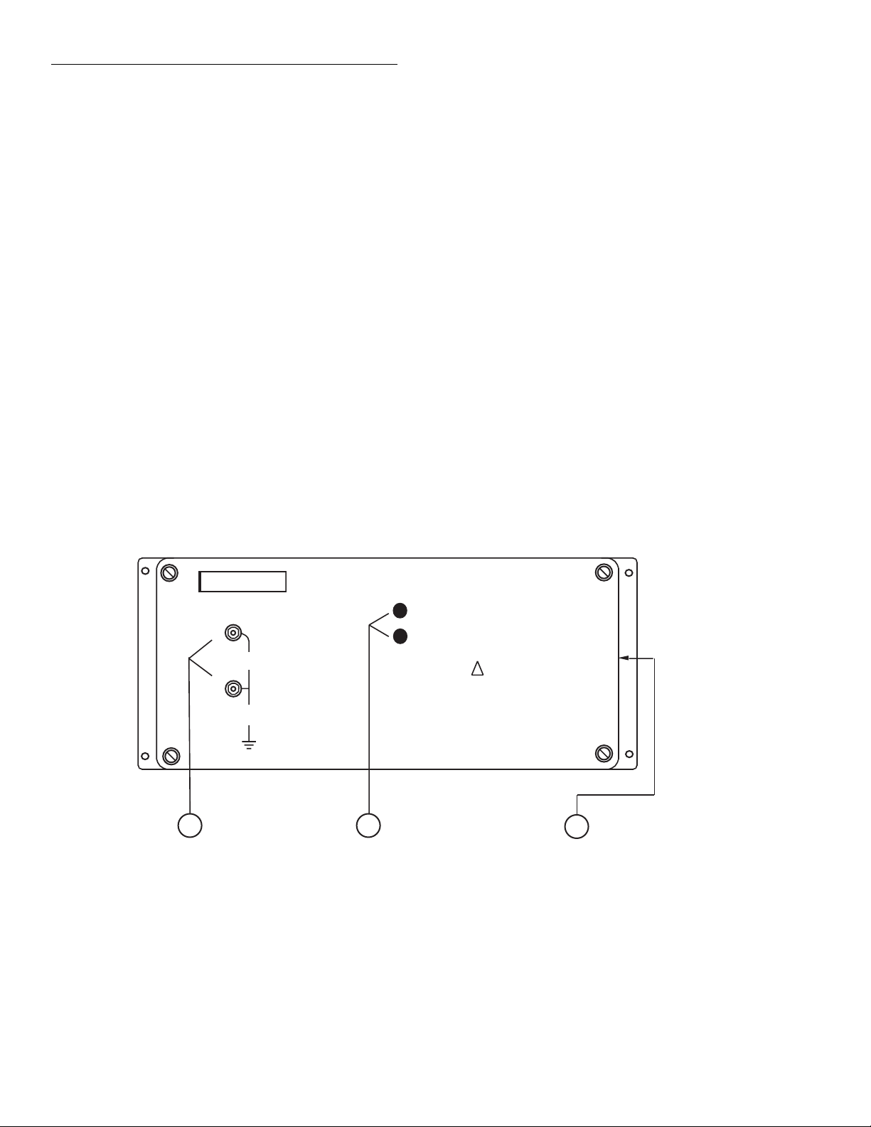
2.2.1 Preamplifier module
Figure 2-1 shows the configuration of the preamplifier
module. Key items include:
❶
INPUT Terminals
The HI and LO INPUT terminals are pure copper studs
and nuts intended for connecting input signals to the
Model 1801. To minimize thermal EMFs, use only pure
copper lugs or wires for connections, and be sure that both
the terminals and connecting lugs are clean and free of
oxidation. See paragraph 2.4.4 for details on input
connections.
CAUTION
The maximum signal between
INPUTS HI and LO is 1V @ 100mA
peak (inputs over 2mV require oneminute recovery). The maximum volt-
age between LO and chassis ground is
41V peak. Exceeding these limits may
result in damage.
❷
Offset Adjustments
V ZERO and I ZERO are externally accessible
adjustments for nulling voltage and current offsets
respectively. These controls need not be adjusted during
normal operation.
NOTE
Improper offset adjustments will
degrade performance. The offset adjustments should only be performed using
the procedures covered in Section 5.
Power Supply Connector
❸
This connector attaches the preamplifier module to the
power supply card using the supplied cable. See paragraph 2.4.1 for details.
KEITHLEY
INPUTS
HI
2mV
PEAK
LO
41V
PEAK
Input
1
Terminals
Figure 2-1
Preamplifier module configuration
1801 NANOVOLT PREAMP
V ZERO
I ZERO
CAUTION:
NO INTERNAL OPERATOR SERVICEABLE PARTS,
SERVICE BY QUALIFIED PERSONNEL ONLY.
Zero
2
Adjustments
!
Power Supply
3
Connector
2-2
Page 17
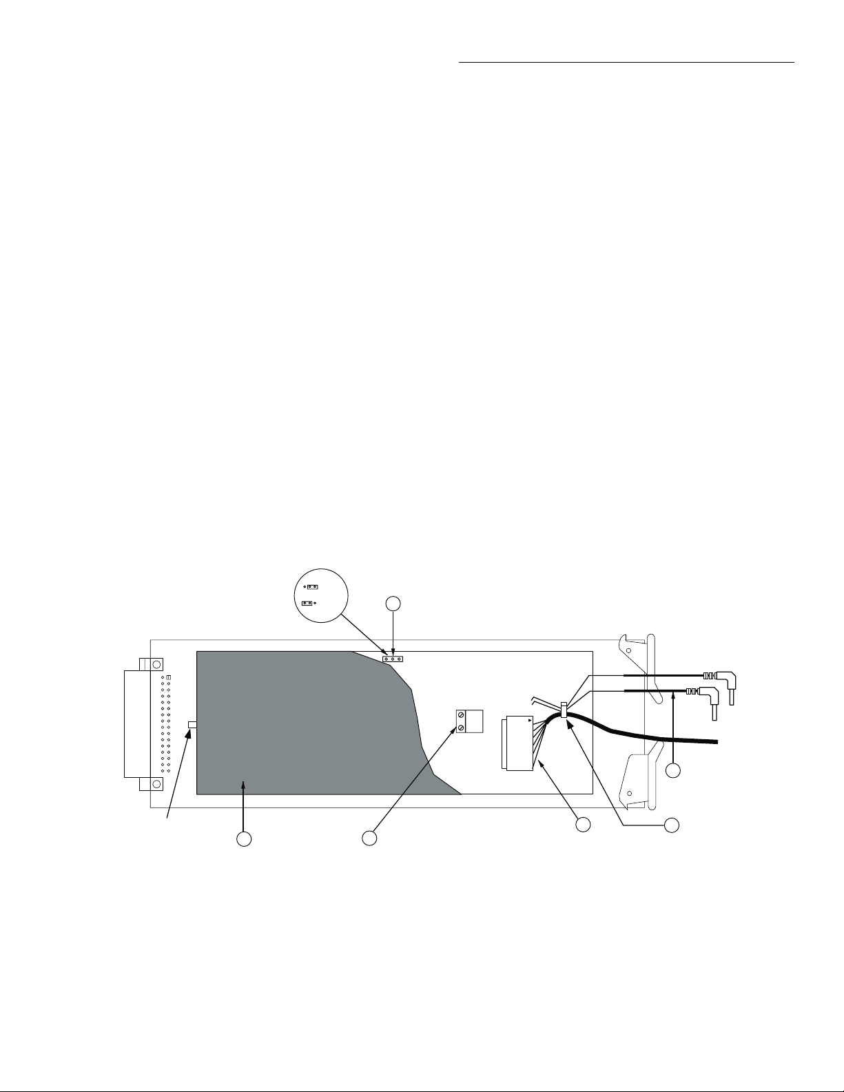
2.2.2 Power supply card
Figure 2-2 shows the configuration of the power supply
card. Components include:
Cover
❶
The plastic cover shields circuit board parts from damage
and contamination. In order to open the cover , press in on
the cover latch, then swing the cover open on its hinges.
Analog Output
❷
The analog output terminals are intended for connecting
the preamplifier output to a monitoring device such as a
chart recorder. See paragraph 2.3 for details.
Power Connector
❸
The power connector and connecting cable supply power
and control signals to the preamplifier module. They also
feed the analog output signal back to the power supply
card.
Installation
❹
Cable Clamp
The cable clamp provides a strain relief for the output
leads and power cable.
Output Leads
❺
The two output leads are terminated with banana plugs
intended to connect to the multimeter input jacks. Red is
HI, and black is LO. See paragraph 2.5.2 for information
on output connections.
❻
Shield Jumper
This jumper allows you to connect the cable shield and
preamplifier shell either to earth ground or to input LO.
Installing the jumper in the earth ground position allows
the unit to meet its stated low common-mode current but
will degrade common-mode noise rejection (if an AC signal is floating on input LO). Installing the jumper in the
LO position will degrade the common-mode current but
will provide the specified common-mode noise rejection.
Cover
Latch
Figure 2-2
Power supply card configuration
1
Cover
LO
Earth
2
Analog
6
Output
Shield Jumper
(W101)
3
Power
connections
5
Output Leads
Cable Clamp
4
2-3
Page 18
Installation
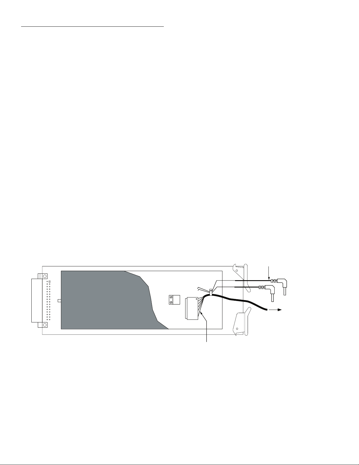
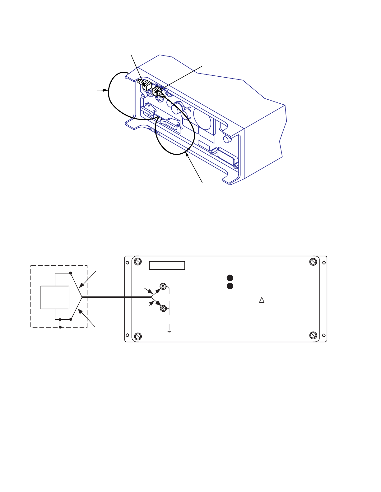
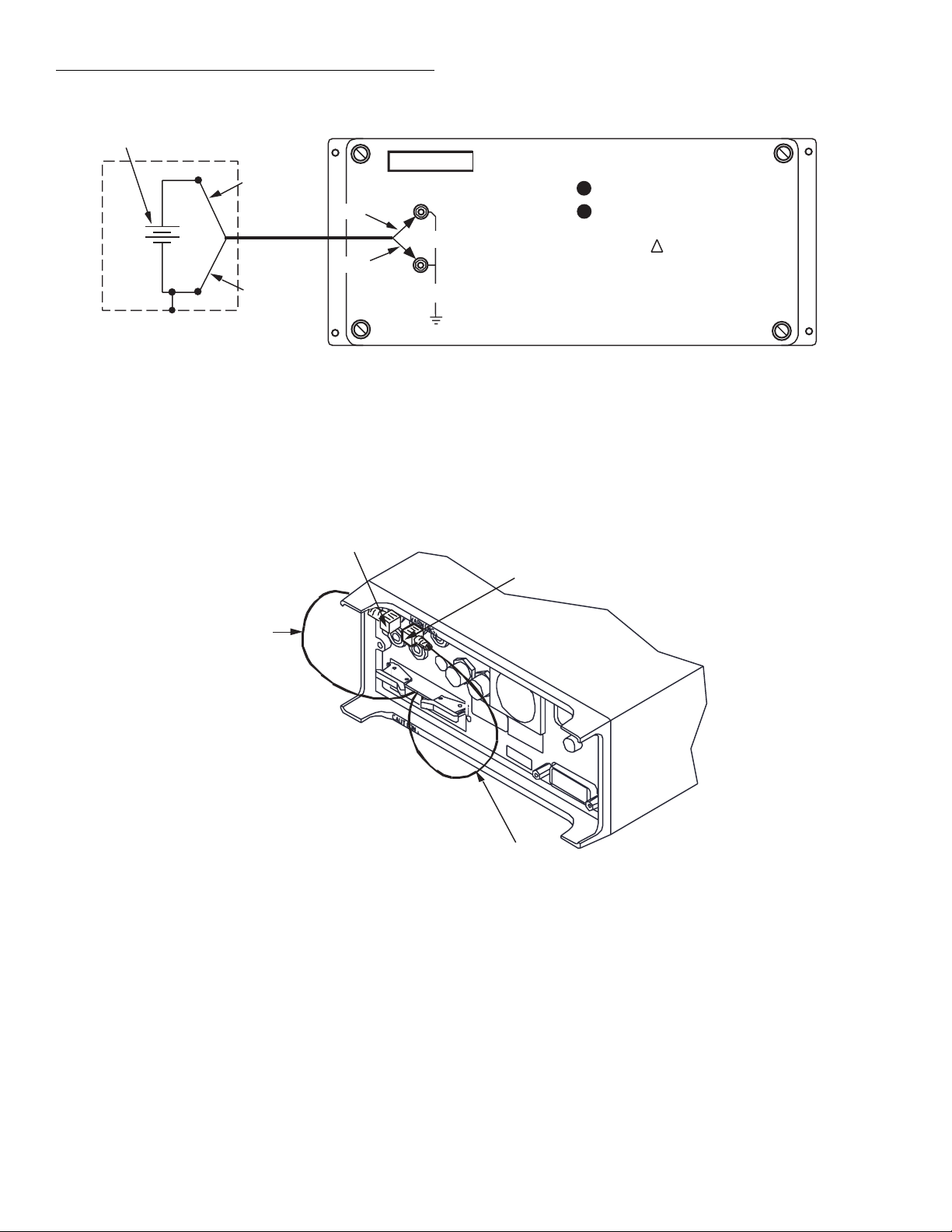
2.3 Power supply card preparation
Power and output connections
Before installing the power supply card in the multimeter ,
make sure the power cable is connected to the po wer connector (see Figure 2-3).
Shield jumper
The shield jumper connects the cable shield and preamp
shell either to earth ground or input LO. This jumper
should be installed as follows:
• If low common-mode current is more important than
common-mode noise rejection, place the jumper in
the earth ground position.
• If common-mode noise rejection is more important
than low common-mode current, place the jumper in
the LO position.
Analog output connections
The analog output terminals, which are located on the
power supply board, provide a 0-2V full scale output for
monitoring devices such as chart recorders.
Since the analog output signal is at a relatively high level
and has low source impedance, the type of wiring used for
connections is not critical. Standard stranded wire of the
type used for DMM test leads should be adequate in most
cases. Figure 2-4 shows typical analog output
connections.
Note that the common-mode current (from LO to earth
ground) of any device connected to the analog output terminals will be added to that of the Model 1801/2001. T ypical common-mode current levels for a DMM or chart
recorder are several micro amps or higher.
Figure 2-3
Power and output connections
Output Connections
To Preamp
Power
Connections
2-4
Page 19
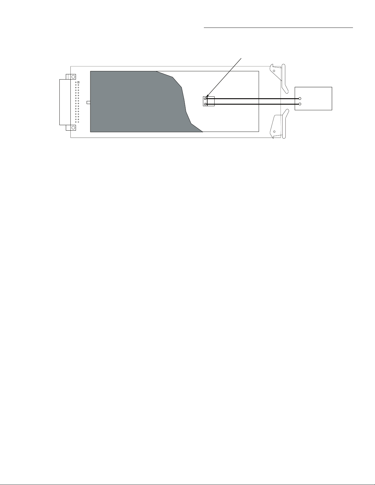
Figure 2-4
Typical analog output connections
Installation
Analog output terminals
HI
LO
Monitoring device
(e.g., chart recorder)
2.4 Power supply card installation and removal
This paragraph explains how to install and remove the
Model 1801 power supply card assembly in the Model
2001 Multimeter.
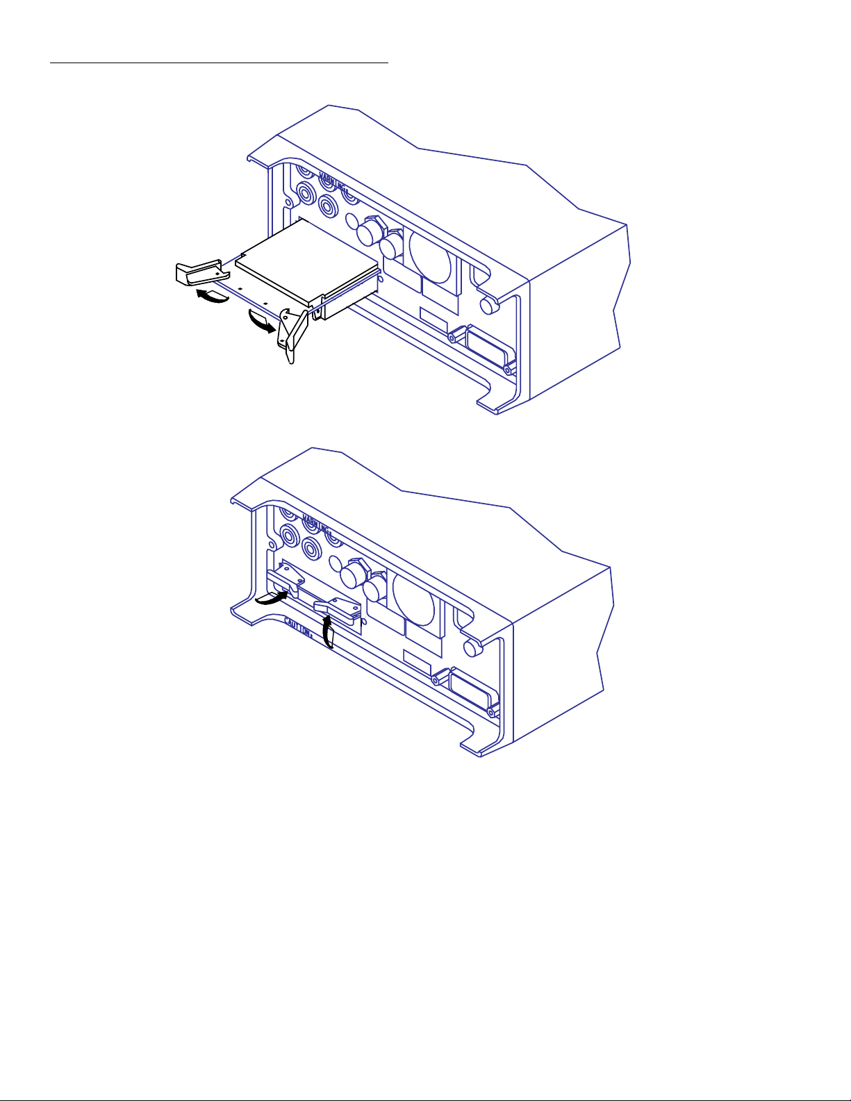
2.4.1 Card installation
Perform the following steps, and refer to Figure 2-5 to
install the power supply card assembly in the Model 2001
Multimeter:
WARNING
Turn off the Model 2001 Multimeter,
and disconnect the line cord before inst
alling or removing the power supply
card.
1. Remove the cover plate labeled OPTION SLOT on
the rear panel of the Model 2001 Multimeter. To do
so, pry out the two fasteners, then remove the cover
plate.
2. Slide the po wer supply card edges into the guide rails
inside the multimeter.
3. With the ejector arms in the unlocked position, carefully push the card all the way forward until the arms
engage the ejector cups. Push both arms inward to
lock the card into the multimeter.
4. After installation, connect the power cable to the
preamp module and the output leads to the multimeter as discussed in paragraph 2.5 below.
2.4.2 Card removal
Follow the steps below to remove the power supply card
from the multimeter:
1. Unlock the card by pulling the latches outward.
2. Carefully slide the card out of the multimeter.
3. If the multimeter is to be operated without the power
supply card installed, install the OPTION SLOT
cover plate.
2-5
Page 20
Installation
Unlock card
Ejector Arms (2)
Lock card
Figure 2-5
Power supply card installation
2.5 Connections
This paragraph provides the information necessary to
connect the preamplifier module to the power supply card
and multimeter.
2-6
2.5.1 Power supply connections
After installing the power supply in the multimeter, connect the preamplifier to the power supply card using the
supplied connecting cable, as shown in Figure 2-6.
Page 21
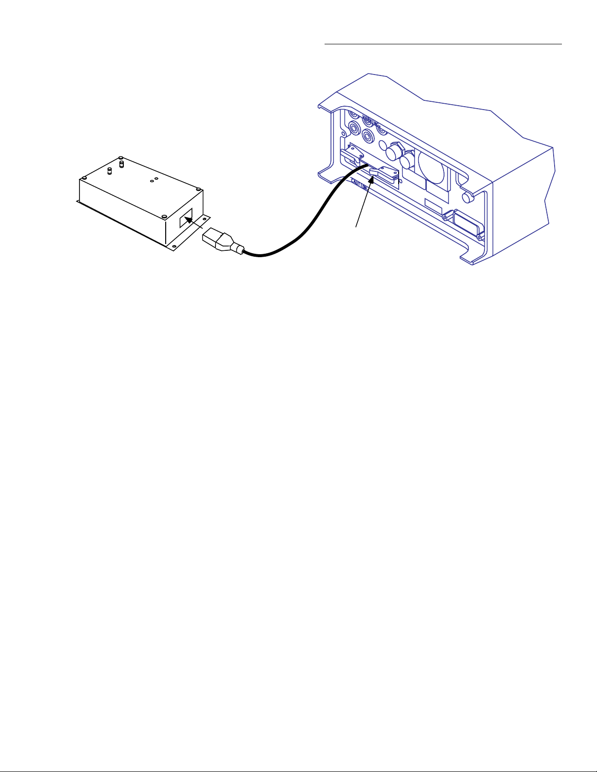
Preamplifier
Module
Insert Plug in
Connector
Power Supply
Cable
Power Supply
Card
Installation
Figure 2-6
Power supply connections
CAUTION
Turn off the Model 2001 Multimeter
power before connecting or disconnecting the cable.
2.5.2 Output connections to multimeter
After installation, connect the output leads to the Model
2001 rear panel input jacks, as shown in Figure 2-7. For
DCV, ACV, frequency, and temperature measurements,
the red lead should be connected to INPUT HI, and the
black lead should be connected to INPUT LO.
NOTE
Be sure to select the rear inputs with the
front panel INPUTS switch when using
the Model 1801. Output connections for
4-wire resistance measurements must be
changed, as explained in paragraph 3.3.2
in Section 3.
• Use only shielded low-thermal cables such as the
input cable supplied with the Model 1801.
• Use only crimped-on copper lugs and copper wires
for all input connections. Crimping results in an airtight connection.
• Copper-to-copper oxide connections result in
thermoelectric potentials as high as 1000µV/°C (see
paragraph 3.4.1). To avoid these thermals, make sure
that all connections are clean and free of oxides.
Scotchbrite® copper cleaner can be used to clean
connections.
• Do not handle the prepared ends of the input cable.
Body oils and salts can result in contamination,
affecting connection integrity.
CAUTION
To avoid possible preamplifier damage, keep static electricity discharge
away from input terminals.
2.5.3 Input signal connections
Input connections are made directly to the two preamplifier screw terminals, as shown in Figure 2-8. When making input connections, observe the following precautions
in order to minimize noise pickup and thermal EMFs:
The supplied input cable can be used for most measurement functions, but some such as thermocouple measurements may require different connecting wires. For input
connection information specific to the type of measurement function, refer to paragraph 3.3 in Section 3.
2-7
Page 22
Installation
Input HI
HI (Red)
NOTES: 1. See paragraph 3.3.3
for 4-wire resistance
output connections.
2. Select rear inputs
using front panel
switch.
Input LO
LO (Black)
Figure 2-7
Connections to multimeter input
HI
DUT
LO
Noise Shield
Red
Low-Thermal
Input Cable
Black
Figure 2-8
Input cable connections
1801 NANOVOLT PREAMP
V ZERO
I ZERO
CAUTION:
NO INTERNAL OPERATOR SERVICEABLE PARTS,
SERVICE BY QUALIFIED PERSONNEL ONLY.
!
Red
Black
KEITHLEY
INPUTS
HI
2mV
PEAK
LO
41V
PEAK
NOTE : 1. Use only clean copper-to-copper connections.
2. See paragraph 3.3 for specific connections
each measurement function.
2-8
Page 23
Installation
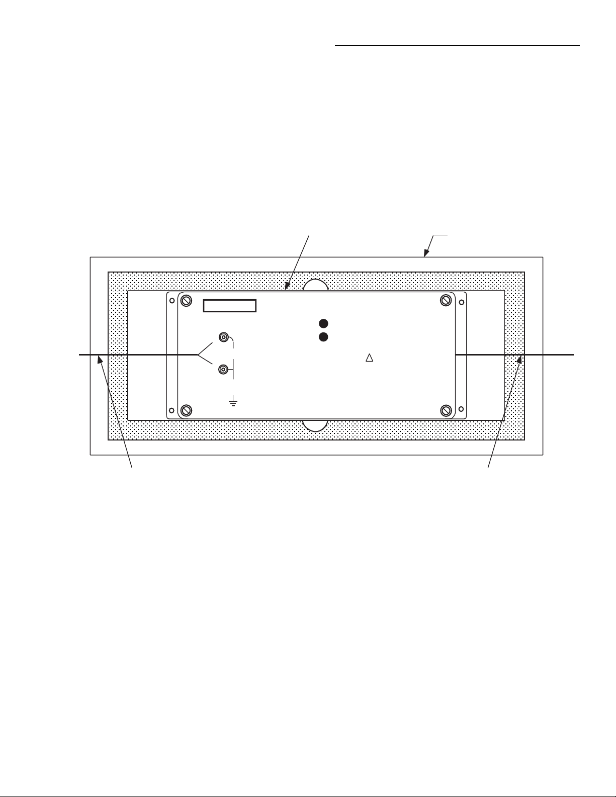
2.6 Operating considerations
2.6.1 Using the thermal isolation container
After making all connections, place the preamplifier module in the thermal isolation container, as shown in Figure
2-9. Route the connecting wires through the slits in each
end of the container, then cover the preamplifier with the
lid. Allow the preamplifier to thermally stabilize for at
least one hour to achieve rated accuracy.
Preamplifier Module
KEITHLEY
INPUTS
HI
2mV
PEAK
LO
41V
PEAK
1801 NANOVOLT PREAMP
2.6.2 Minimum operating distance
The Model 1801 preamplifier module should be kept a
minimum of two feet away from the Model 2001 Multimeter and other instrumentation to avoid noise pickup due
to stray magnetic fields.
Foam Thermal
Insolation Container
V ZERO
I ZERO
CAUTION:
NO INTERNAL OPERATOR SERVICEABLE PARTS,
SERVICE BY QUALIFIED PERSONNEL ONLY.
!
Route
Input cable
through slit
Figure 2-9
Using the thermal isolator container
Route Power
Supply cable
through slit
2-9
Page 24

3
Operation
3.1 Introduction
This section contains basic information on operating the
Model 1801 using the host Model 2001 Multimeter. For
more detailed information on operating the Model 2001
Multimeter, see the Model 2001 Operator’s Manual.
This section is organized as follows:
3.2 Preamplifier operation: Covers enabling Model
1801 operation, preamplifier filtering, operating
restrictions, and summarizes IEEE-488 bus
operation.
3.3 Measurements: Discusses DC and AC voltage
measurements, and 4-wire resistance and thermocouple temperature measurements.
3.4 Measurement considerations: Explains a number
of considerations that may apply to Model 1801
measurements.
3.2 Preamplifier operation
3.2.1 Power-up detection
If, however, the preamplifier is enabled at power-on, the
unit will display the following message:
Preamp ON
Whether the Model 1801 is enabled or disabled at poweron depends on the programmed power-on setup:
• GPIB defaults: Model 1801 always disabled.
• Bench defaults: Model 1801 always enabled.
• User setup: Model 1801 either enabled or disabled
depending on the state stored in the recalled setup.
See paragraph 3.2.5 for additional information on saving
and recalling setups. Paragraph 3.12.1 of the Model 2001
Operator’s Manual explains how to select the instrument
setup that goes into effect at power-on.
Note that you can query the instrument over the IEEE-488
bus to determine if the Model 1801 is present by using the
*OPT? query. If the preamplifier is present, the instrument will return the following response:
The Model 2001 Multimeter automatically detects the
presence of the Model 1801 at power-on. The instrument
will indicate the presence of the Model 1801 by displaying the following message if the preamplifier is disabled:
Preamp OFF
2001-1801
Refer to paragraph 4.9 of the Model 2001 Multimeter
Operator’s Manual for more details on using the *OPT?
query.
3-1
Page 25

Operation
Power-up error messages
T able 3-1 summarizes error messages that may occur dur ing power-up when the Model 1801 is installed.
3.2.2 Preamplifier configuration menu
Table 3-2 summarizes the preamplifier configuration
menu structure. In order to access this menu, press the
front panel CHAN key.
3.2.3 Enabling Model 1801 operation
Follow the procedure below to enable Model 1801
operation:
1. Press the CHAN key. The Model 2001 will display
the following:
CONFIGURE PREAMP
CONTROL FILTER CALIBRATION
3. Select ENABLE, then press ENTER.
4. Press EXIT to return to normal display. The unit will
display the following message to indicate that the
preamplifier is enabled:
Preamp ON
5. To disable the preamplifier, repeat steps 1 through 4,
but select DISABLE in the PREAMP CONTROL
menu. The unit will display the following to indicate
that the preamplifier is disabled:
Preamp OFF
NOTE
Once Model 1801 operation is enabled,
readings will be scaled accordingly . Disable Model 1801 operation if you intend
to make measurements without the
Model 1801. Otherwise, incorrect readings will be displayed.
2. Select CONTROL, then press ENTER. The unit will
display the following:
PREAMP CONTROL
ENABLE DISABLE
Table 3-1
Power-up error messages
Error number Message Description
-315
+516
+517
“Preamp memory lost”
“Installed option id lost”
“Preamp calibration data lost”
3.2.4 Preamp ON/OFF states
Table 3-3 summarizes operating states the Model 2001
will assume when the preamp is turned on or off.
Cannot recover preamp setup due to corrupt memory.
Cannot identify Model 1801 as installed option.
Preamplifier uncalibrated due to lost cal constants.
3-2
Page 26

Table 3-2
CONFIGURE PREAMP menu structure
Menu item Description
Operation
CONTROL
ENABLE
DISABLE
FILTER
FAST
MEDIUM
SLOW
CALIBRATION
CALIBRATION-DATES
CALIBRATE
ENTER-CAL-CONSTANTS
NOTE: Press CHAN key to access CONFIGURE PREAMP menu. See Section 5 for
calibration information.
Table 3-3
Preamp ON/OFF states
Enable/disable preamplifier.
Enable preamplifier.
Disable preamplifier.
Select preamplifier filter.
Select fast response filter.
Select medium response filter.
Select slow response filter.
Calibrate preamplifier.
Set calibration dates.
Calibrate preamplifier.
Input calibration constants.
Mode Preamp ON Preamp OFF
DCV Range
DCV Auto-range
ACV Range
ACV Auto-range
ACV Type
Ω4W Range
Ω4W Auto-range
FREQ Voltage Threshold Range
FREQ Voltage Threshold Level
TEMP Transducer
NOTE: This table lists operating states that change when preamp is enabled or disabled. All other
states are unaffected by enabling or disabling preamp.
2mV
OFF
500µV
OFF
Low-frequency RMS
200Ω
OFF
2mV
0
Differential thermocouple
1000V
ON
750V
ON
Normal RMS
200kΩ
ON
1V
0
4-wire RTD
3-3
Page 27

Operation
3.2.5 Preamplifier filtering
The Model 1801 has three analog filters with FAST,
MEDIUM, and SLOW responses respectively. These filters are in addition to the Model 2001 filter, which can
also be used with the preamplifier. See paragraph 3.9 of
the Model 2001 Operator’s Manual for details on Model
2001 filtering.
The following paragraphs discuss selecting the filter
response and also cover filter frequency response curves.
See the specifications in Appendix A for filter settling
times.
Selecting filter response
1. Press the CHAN key to bring up the preamplifier
configuration menu. The instrument will display the
following:
CONFIGURE PREAMP
CONTROL FILTER CALIBRATION
2. Select FILTER, then press ENTER. The unit will display filter response selections:
SELECT PREAMP FILTER
FAST MEDIUM SLOW
3. Select the desired filter response, then press ENTER.
The FAST response filter provides the least noise
reduction and fastest response, while the SLOW
response filter gives the most noise reduction and
slowest response. Note that only the FAST response
filter is available with the ACV and FREQ functions.
4. Press EXIT to return to normal display.
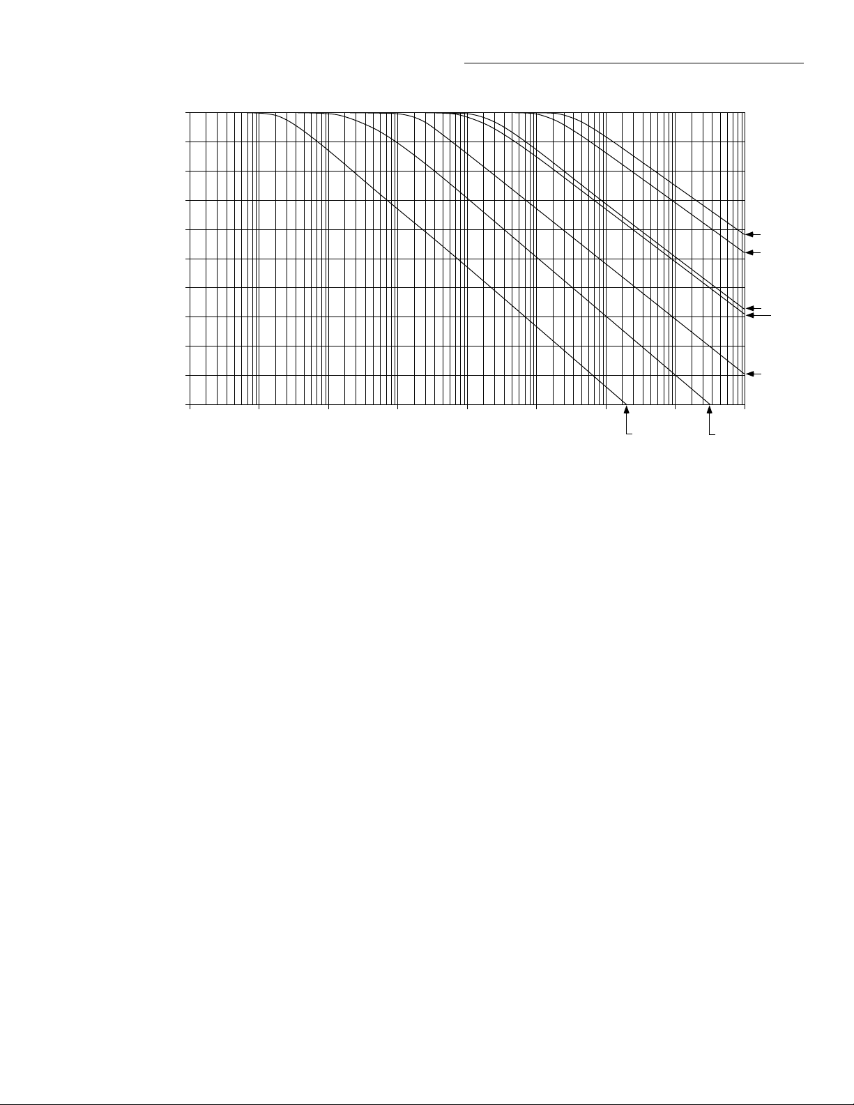
Filter frequency response curves
Each of the preamplifier filters exhibits single-pole, lowpass response. In addition to the filter selection, filter
response also depends on the selected range, as summarized in Table 3-4. The table includes the -3dB response
point for each set of operating conditions, as well as a filter response number. The filter frequency response number corresponds to the equivalent curve number shown in
Figure 3-1. Note that the filter response curves shown are
for the preamplifier only and do not include Model 2001
response, which is affected by its own filter parameters as
well as the selected integration period.
Table 3-4
Filter response parameters
Filter response
FAST MEDIUM SLOW
Function and Range
DCV: 20µV
-3dB
bandwidth
40Hz 3 0.32Hz 6 0.032Hz 7
Filter
number
-3dB
bandwidth
Filter
number
-3dB
bandwidth
Ω4W None
DCV: 200µV
185Hz 2 3.2Hz 5 0.32Hz 6
Ω4W: 2mΩ
DCV: 2mV
700Hz 1 32Hz 4 3.2Hz 5
Ω4W: 20mΩ–200Ω
NOTE: Filter numbers correspond to curves shown in Figure 3-1. FAST filter only for ACV and FREQ functions.
10%-90% risetime = 0.35/Bandwidth (Hz)
τ (s) = 0.15/Bandwidth (Hz)
Filter
number
3-4
Page 28
-10
-20
-30
Operation
0
-40
dB
Gain
-50
-60
-70
-80
-90
-100
0.001 0.01 0.1 1 10 100 1k 10k 100k
NOTE : Response curves are for preamplifier only.
Number corresponds to conditions listed in
Table 3-4.
Figure 3-1
Filter frequency response curves
3.2.6 Operational differences
Functions
Frequency (Hz)
select one of these functions when the Model 1801 is
enabled:
1
2
3
4
5
67
The following functions are available when using the
Model 1801:
• DC volts
• AC volts (low-frequency RMS only)
• 4-wire ohms
• Frequency (voltage only)
• Thermocouple temperature (differential only)
Note that DC current, AC current, and 2-wire ohms functions are not available when the preamp is turned on. The
following message will be displayed if you attempt to
Function is not available with Preamp enabled
Ranging
Table 3-5 summarizes the measurement ranges available
when using the Model 1801. Note that auto-ranging cannot be used when the preamplifier is enabled. If you
attempt to use auto-ranging with the preamp turned on,
the instrument will display the following message:
Auto-ranging is not available with Preamp enabled
3-5
Page 29

Operation
■
■
■
Ω
Ω
Table 3-5
Preamplifier measurement ranges
Function Ranges
DCV
ACV
4W
Frequency* 2mV
* Maximum threshold level range.
Saving setups
Model 1801 setups can be saved by using the
SAVESETUP selection in the front panel menu. (See
paragraph 3.12.1 of the Model 2001 Operator’s Manual
for details.) In order to save a preamplifier setup, select
the desired operating conditions, then save your setup as
usual. To turn on the Model 1801 when the setup is
recalled, first enable the preamplifier before saving the
setup. To turn off the preamplifier when the setup is
recalled, disable the preamplifier before saving the setup.
20µV, 200µV, 2mV
500µV RMS
2m Ω , 20m Ω , 200m Ω , 2 Ω , 20 Ω , 200 Ω
Table 3-6
Factory default conditions
Function or operation Factory default
Function
DCV Range
ACV Range
Ohms Range
Ohms Offset Compensation
Frequency Threshold Range
Frequency Threshold Level
T emperature Transducer
Filter Response
User setups
When a user setup is recalled, the Model 1801 operating
state assumes the condition dictated by the recalled setup.
If the setup was stored with the Model 1801 disabled, the
preamplifier will be disabled when the setup is recalled. If
the setup was stored with the Model 1801 enabled, the
preamplifier will be enabled when the setup is recalled,
and the instrument will assume operating conditions from
the recalled setup.
DCV
2mV
500µV
200
On
2mV
0V
Differential
Thermocouple
Medium
Recalling setups
The state of the Model 1801 depends on the type of setup
being recalled: GPIB defaults, bench defaults, or user
setup.
GPIB defaults
When GPIB defaults are recalled, the Model 1801 is
always disabled. GPIB defaults are restored with the
RESET GPIB selection in the save setup menu, or by
sending the *RST command over the bus.
Bench defaults
When bench defaults are recalled, any internal conflicts
(such as auto-range) with the present operating state are
resolved, and the Model 1801 is enabled with the factory
default operating conditions summarized in Table 3-6.
Bench defaults can be recalled by using the RESET
BENCH selection in the save setup menu, or by using the
bus :SYSTem:PRESet command.
Notes:
1. If a recalled setup requires that the Model 1801 be
enabled, and the preamplifier is not installed in the
Model 2001, a “Missing hardware” error will be generated. The Model 2001 will then assume its bench
default conditions.
2. The preamplifier hardware gain is set to X1,000, and
the filter response is set to medium when the Model
1801 is disabled.
Multiple displays
The following multiple displays are not available when
using the Model 1801:
• DCV: positive, negative, or positive/negative peak
spikes; ACV frequency; simultaneous DCV/ACV.
• ACV: crest factor, frequency.
• FREQ: period
3-6
Page 30

Operation
An appropriate error message will be displayed if you
select one of the above multiple displays with the preamp
enabled. Also note that the FREQ bar graph range is limited to 2kHz with the preamp enabled. See paragraph
3.2.2 of the Model 2001 Operator’s Manual for more
information on using the multiple displays.
3.2.7 IEEE-488 bus operation
Table 3-7 summarizes additional IEEE-488 bus commands necessary for preamplifier configuration. In general, most of the IEEE-488 bus commands covered in
Section 4 of the Model 2001 Operator’s Manual can be
used with the Model 1801. Howev er, the same operational
restrictions discussed in paragraph 3.2.5 apply to bus programming. If you send an invalid program message, an
error will result.
NOTE
Additional commands that control differential thermocouple temperature
operation are explained in paragraph
3.3.5.
Example 1: Enable Preamplifier
:INP:PRE:STAT ON
or,
:INPUT:PREAMP:STATE 1
Example 2: Select Filter Response
:INP:PRE:FILT MED
or,
:INPUT:PREAMP:FILTER MEDIUM
3.3 Measurements
3.3.1 DC voltage measurements
The Model 1801 can detect DC voltages as low as 1pV
and measure up to 2mV. Assuming “bench reset” conditions (see paragraph 3.12.1 of the Model 2001 Operator’ s
Manual), the basic procedure for making DC voltage
measurements is as follows:
Table 3-7
Preamplifier configuration commands
Command Description
:INPut
:PREamp
:STATe <b>
:STATe?
:FILTer <name>
:FILTer?
Notes:
1. Angle brackets (<>) are used to indicate parameter type. Do not
include brackets in programming message.
2. Upper-case letters indicate command short form.
Enables (ON or 1) or dis-
ables (OFF or 0) preamplifier.
Returns preamp state (1=ON
or 0=OFF)
Selects preamp filter
response (Name = SLOW |
MEDium | FAST)
Returns preamplifier state
(SLOW, MED, or FAST)
1. Connect the input cable to the INPUTS terminals on
the preamplifier module, and connect the output leads
to the Model 2001 rear panel INPUT jacks (see Figure 3-2).
2. Set the INPUTS switch to the REAR position.
3. Press CONFIG DCV, then configure the speed, filter,
and resolution as required.
4. Press the DCV key to select the DC volts function.
5. Using the RANGE keys, choose a range consistent
with the expected voltage. (Available ranges are:
20µV, 200µV, and 2mV.)
6. Connect the input leads to the voltage source, as
shown in Figure 3-2.
CAUTION
Do not exceed 1V peak at 100mA
between the INPUTS HI and LO
terminals, or the preamplifier may be
damaged. (Inputs over 2mV peak will
require a one-minute recovery period.)
3-7
Page 31
Operation
DC V oltage
Source
Noise Shield
HI
LO
Red
Low-Thermal
Input Cable
Black
Red
Black
KEITHLEY
INPUTS
HI
2mV
PEAK
LO
41V
PEAK
NOTE : Use only clean copper-to-copper connections.
1801 NANOVOLT PREAMP
V ZERO
I ZERO
CAUTION:
NO INTERNAL OPERATOR SERVICEABLE PARTS,
SERVICE BY QUALIFIED PERSONNEL ONLY.
!
a. Input Connections
Input HI
HI (Red)
Figure 3-2
Connections for DC voltage measurements
Input LO
LO (Black)
b. Output Connections
3-8
Page 32

Operation
7. Observe the display. If the “Overflow” message is
displayed, select a higher range. Use the lowest range
possible for the best resolution.
8. Take a reading from the display. If the reading is
noisy, it may be necessary to change the filter
response. (See paragraph 3.2.5 for details on
filtering.)
Zeroing
The specification term “when properly zeroed” means
that you must establish a baseline for subsequent measurements on that range. All Model 1801 DCV ranges
require proper zeroing to achieve rated accuracy. The
zeroing procedure described below should be performed
at the interval and changes in ambient temperature given
in the specifications in Appendix A.
To zero (rel) the Model 1801, follow the steps below:
1. Disable rel if presently enabled by pressing the REL
key. The REL annunciator should be off.
2. Select the range to be used for the measurement.
3. Disconnect the input leads from the signal source,
then short the ends of the leads together. Allow sufficient time for thermal offsets and noise to stabilize.
4. Press the REL key. The display will read zero.
5. Remove the short, and connect the input leads to the
signal to be measured.
3.3.2 AC voltage measurements
The Model 1801 can detect low-frequency RMS AC
voltages as low as 100pV and measure a maximum of
500µV RMS. Assuming “bench reset” conditions (see
paragraph 3.12.1 of the Model 2001 Operator’s Manual),
the basic procedure for making A C v oltage measurements
is as follows:
1. Connect the input cable to the INPUTS terminals on
the preamplifier module, and connect the output leads
to the Model 2001 rear panel INPUT jacks (see Figure 3-3).
2. Set the INPUTS switch to the REAR position.
3. Press CONFIG ACV, then select the desired operating conditions.
4. Press the ACV key to select the AC volts function.
5. Connect the input leads to the voltage source, as
shown in Figure 3-3.
CAUTION
Do not exceed 1V peak at 100mA
between the INPUTS HI and LO terminals, or the preamplifier may be
damaged. (Inputs over 2mV peak will
require a one-minute recovery period.)
6. Take a reading from the display.
3-9
Page 33

Operation
AC V oltage
Source
Noise Shield
HI
LO
Red
Low-Thermal
Input Cable
Black
Red
Black
KEITHLEY
INPUTS
HI
2mV
PEAK
LO
41V
PEAK
NOTE : Use only clean copper-to-copper connections.
1801 NANOVOLT PREAMP
V ZERO
I ZERO
CAUTION:
NO INTERNAL OPERATOR SERVICEABLE PARTS,
SERVICE BY QUALIFIED PERSONNEL ONLY.
!
a. Input Connections
Input HI
HI (Red)
Figure 3-3
Connections for AC voltage measurements
Input LO
LO (Black)
b. Output Connections
3-10
Page 34

Operation
Ω
3.3.3 Four-wire resistance measurements
The Model 1801 can make 4-wire resistance measurements between 100p
reset” conditions (see paragraph 3.12.1 of the Model 2001
Operator’s Manual), the basic procedure for making
4-wire resistance measurements is as follows:
1. Connect the input cable to the INPUTS terminals on
the preamplifier module, and connect the output leads
to the rear panel SENSE 4 WIRE jacks (see Figure
3-4). Also connect test leads to the rear panel HI and
LO INPUT jacks (these leads are necessary to apply
the source current to the DUT necessary for 4-wire
resistance measurements).
2. Set the INPUTS switch to the REAR position.
3. Press CONFIG
resistance operating conditions.
4. Press the Ω4 key to select the 4-wire ohms function.
5. Using the RANGE keys, choose a range consistent
with the expected resistance. (Available ranges are
from 2mΩ to 200Ω in decade steps.)
6. Connect the preamplifier input leads and the DMM
HI and LO INPUT leads to the resistance being measured, as shown in Figure 3-4.
7. Observe the display. If the “Overflow” message is
displayed, select a higher range. Use the lowest range
possible for the best resolution.
8. Take a reading from the display. If the reading is
noisy, it may be necessary to change the filter
response. (See paragraph 3.2.5 for details on
filtering.)
Zeroing
The specification term “when properly zeroed” means
that you must establish a baseline for subsequent
measurements on that range. All Model 1801 4-wire
resistance ranges require proper zeroing to achieve rated
accuracy. The zeroing procedure described below should
be performed at intervals and changes in ambient
temperature given in Appendix A.
To zero (rel) the Model 1801, follow the steps below:
1. Disable rel if presently enabled by pressing the REL
key. The REL annunciator should be off.
2. Select the range to be used for the measurement.
3. Disconnect all four leads from the signal source, then
short the ends of all four test leads together. Allow
and 200 Ω . Assuming “bench
Ω4, then select the desired four-wire
sufficient time for thermal offsets and noise to
stabilize.
4. Press the REL key. The display will read zero.
5. Remove the short, and connect all four test leads to
the resistance to be measured.
Offset-compensated ohms
Offset-compensated ohms compensates for voltage
potentials such as thermal EMFs across the device under
test. For maximum accuracy, offset compensation should
be used for all Model 1801 resistance measurements.
Offset compensation can be enabled or disabled by
pressing CONFIG Ω4, and then selecting
OFFSETCOMP in the CONFIGURE OHMS-4W menu.
See paragraph 3.4.3 of the Model 2001 Operator’ s Model
for additional information.
3.3.4 Frequency measurements
The Model 1801 can make A CV frequency measurements
between 1Hz and 1kHz. Assuming “bench reset” conditions (see paragraph 3.12.1 of the Model 2001 Operator’ s
Manual), the basic procedure for making ACV frequency
measurements is as follows:
1. Connect the input cable to the INPUTS terminals on
the preamplifier module, and connect the output leads
to the rear panel INPUT jacks (see Figure 3-5).
2. Set the INPUTS switch to the REAR position.
3. Press CONFIG FREQ, then choose the desired frequency measurement configuration.
4. Press the FREQ k ey to select the frequenc y function.
5. Connect the input leads to the AC voltage source, as
shown in Figure 3-5.
CAUTION
Do not exceed 1V peak at 100mA
between the INPUTS HI and LO terminals, or the preamplifier may be
damaged. (Inputs over 2mV will
require a one-minute recovery period.)
6. Take a frequency reading from the display.
3-11
Page 35

Operation
Resistor
Under
Test
HI
LO
Noise Shield
Sense HI
Sense LO
Red
Low-Thermal
Input Cable
Black
Red
Black
Input HI
KEITHLEY
INPUTS
HI
2mV
PEAK
LO
41V
PEAK
NOTES : 1. Use only clean copper-to-copper connections.
2. Sense voltage inside current leads as close to DUT
as possible.
1801 NANOVOLT PREAMP
V ZERO
I ZERO
CAUTION:
NO INTERNAL OPERATOR SERVICEABLE PARTS,
SERVICE BY QUALIFIED PERSONNEL ONLY.
!
Input LO
Output
Connections
Figure 3-4
Connections for 4-wire resistance measurements
3-12
Page 36

Frequency
Source
Noise Shield
HI
LO
Red
Low-Thermal
Input Cable
Black
Red
Black
KEITHLEY
INPUTS
HI
2mV
PEAK
LO
41V
PEAK
NOTE : Use only clean copper-to-copper connections.
1801 NANOVOLT PREAMP
V ZERO
I ZERO
CAUTION:
NO INTERNAL OPERATOR SERVICEABLE PARTS,
SERVICE BY QUALIFIED PERSONNEL ONLY.
!
a. Input Connections
Operation
Input HI
HI (Red)
Figure 3-5
Connections for frequency measurements
Input LO
LO (Black)
b. Output Connections
3-13
Page 37

Operation
3.3.5 Differential thermocouple temperature
measurements
The Model 1801 can make differential temperature measurements using two thermocouples connected in a differ ential configuration. The Model 2001 will then display the
difference in temperature between the two thermocouples. The temperature is calculated by using the slope of
the thermocouple V-T curve. To keep the change in slope
small, the approximate range of measurement is restricted
to ±50°C.
For the seven standard supported thermocouples (J, K, T,
E, R, S, B), you must enter the temperature at which the
reference thermocouple will be operated during measurement. If an inv alid reference temperature is used, the reading will appear as an “Overflow”.
To allow for other thermocouple or thermopile types, a
USER type thermocouple is included in the selection
menu. In order to use this selection, you must enter the
thermocouple slope (coefficient) in µV/°C. If the USER
thermocouple type is selected, it is not necessary to enter
the reference temperature since the thermocouple slope is
already known.
Note that differential thermocouples can only be measured with the Model 1801 installed and enabled; otherwise pertinent setup menus will not be available. Also, a
differential thermocouple configuration is the only type of
temperature sensor allowed when the Model 1801 is
enabled.
Note that thermocouples should be connected so that the
conductor type with the lower Seebeck coefficient relati ve
to copper is connected to the preamp input terminals. For
example, type T is copper-constantan, and the copper
leads would be connected to the input terminals.
Differential temperature menu
Table 3-8 summarizes the temperature configuration
menu as it appears when the Model 1801 is enabled. Press
CONFIG TEMP to access this menu, then make your
selections accordingly.
Table 3-8
CONFIG TEMPERATURE menu with Model 1801 enabled
Menu item Description
SENSOR
DIFF-TC SETUP
THERMOCOUPLE TYPE
J K T E R S B USER-SPECIFIED-SLOPE
REF-TEMP
REFTEMP = +0000.00 °
UNITS
SPEED
FILTER
RESLN
SET TEMP RESOLUTION
AUTO 10m° 1m° 0.1m° 0.01m° 1µ°
Select sensor type.
Differential TC setup.
Select thermocouple type.
Set reference TC temperature
Same as normal 2001 operation.
Same as normal 2001 operation.
Same as normal 2001 operation.
Select resolution.
Set temperature resolution.
3-14
Page 38

Operation
Front panel measurement procedure
The basic procedure for differential thermocouple temperature measurement is as follows:
1. Connect the two thermocouples to the Model 1801
input in a differential configuration, as shown in Figure 3-6.
NOTE
Both thermocouples must be of the same
type, or erroneous temperature readings
will be displayed.
2. Press CONFIG TEMP. The instrument will display
the following:
CONFIG TEMPERATURE
SENSOR UNITS SPEED FILTER RESLN
3. Select SENSOR, then press ENTER. The Model
2001 will display the following:
DIFF-TC SETUP
THERMOCOUPLE-TYPE REF-TEMP
4. Select THERMOCOUPLE-TYPE, then press
ENTER. The display will appear as follows:
DIFFERENTIAL TC TYPE
JKTERSB
USER-DEFINED-SLOPE
5. Select either one of the standard thermocouples, or
the USER-SPECIFIED-SLOPE, then press ENTER.
6. If you ha ve selected one of the standard thermocouple
types, select REF-TEMP, then press ENTER. The
Model 2001 will display the reference thermocouple
temperature:
REFTEMP=+0000.00 ¡C
7. Set the reference thermocouple temperature (T1 or
T2 in Figure 3-6) using the range and cursor keys,
then press ENTER, and go on to step 11.
8. If you selected USER-SPECIFIED-SLOPE in step 6,
the instrument will prompt you to enter the thermocouple slope in µV/°C as follows:
SLOPE=+00020.0 µV/¡C
9. Use the range and cursor keys to set the slope to the
correct value, then press ENTER.
10. Press EXIT. The display will appear as follows:
CONFIG TEMPERATURE
SENSOR UNITS SPEED FILTER RESLN
11. Select RESLN, then press ENTER. The instrument
will display the temperature resolution menu:
SET TEMP RESOLUTION
AUTO 10m¡ 1m¡ 0.1m¡ 0.01m¡
1µ¡
12. Select the desired temperature display resolution,
then press ENTER.
13. Select the remaining temperature operating parameters using the UNITS, SPEED, and FILTER menu
selections, as required.
14. Press EXIT to return to normal display.
15. Press TEMP . The instrument will then display the difference in temperature between the reference thermocouple and the measuring thermocouple. The Model
2001 display will indicate the differential temperature and the type of thermocouple as in the following
example:
+00.00 ¡C
Diff TC: User Preamp ON
Note that the display resolution and units will depend on
the corresponding selected menu items, while the displayed thermocouple type will, of course, depend on the
type of thermocouple previously selected.
3-15
Page 39

Operation
T
1
Thermocouples connected
in differential configuration
T
2
Note:
Connect leads with lower
Seebeck coefficient relative
to copper to preamp.
HI (Red)
-
+
KEITHLEY
INPUTS
HI
2mV
PEAK
LO
41V
PEAK
1801 NANOVOLT PREAMP
V ZERO
I ZERO
CAUTION:
NO INTERNAL OPERATOR SERVICEABLE PARTS,
SERVICE BY QUALIFIED PERSONNEL ONLY.
!
-
a. Input Connections
Input HI
Input LO
b. Output Connections
Figure 3-6
Connections for differential temperature measurements
3-16
LO (Black)
Page 40

Operation
Temperature displays
It is important to keep in mind that, with the Model 1801
enabled, the Model 2001 always displays the difference in
temperature between the reference thermocouple and the
measuring thermocouple in the currently selected temperature units (°C, °F , or K). This characteristic may result in
confusion, particularly when temperature units are
changed.
As an example, assume that the reference thermocouple is
located in an ice-point reference at 0°C (32°F), and that
the measuring thermocouple is at 23°C (73.4°F). With °C
units selected, the instrument will, of course, display a
differential temperature of 23°C. If the display units are
then changed to °F, the displayed temperature now
becomes 41.4°F (73.4 - 32 = 41.4).
Example 1: °C Display
Reference thermocouple temperature: 23°C
Measuring thermocouple temperature: 45°C
Displayed temperature: 22°C
Example 2: °F Display
Reference thermocouple temperature: 73.4°F
Measuring thermocouple temperature: 113°F
Displayed temperature: 39.6°F
range of the selected thermocouple type. Otherwise, the
temperature bar graphs operate essentially in the same
manner as described in paragraph 3.3.2 of the Model 2001
Operator’s Manual.
IEEE-488 bus temperature commands
Table 3-9 summarizes additional bus commands associated with the Model 1801 temperature measurement function. The :DTC:TYPE command is used to select the type
of thermocouple to be used for the differential temperature measurement. If you select one of the standard thermocouple types (J, K, T, E, R, S, or B), you must also
program the reference thermocouple temperature using
the :DTC:RTEM command. If you choose the USER ther mocouple type, you must also program the slope (coefficient) of the thermocouple using the :DTC:USLOPE
command. Note that the slope is programmed in V/°C
over the bus instead of the µV/°C units used from the front
panel.
Example 1: Select Thermocouple Type
The following command would be sent to select a J-type
thermocouple:
:TEMP:DTC:TYPE J
Example 2: Program Reference Temperature
Example 3: K Display
Reference thermocouple temperature: 296K
Measuring thermocouple temperature: 318K
Displayed temperature: 22K
Temperature bar graph displays
When the Model 1801 is enabled, the temperature bar
graph display limits are reduced to reflect the ±50°C temperature range of the Model 1801 regardless of the normal
The following command would be sent to program a reference temperature of 23°:
:TEMP:DTC:RTEM 23
Example 3: Program User Thermocouple Slope
The command below will program a thermocouple slope
of 10µV/°C:
:TEMP:DTC:USL 10E-6
3-17
Page 41

Operation
Table 3-9
Differential temperature bus commands
Command Description
[:SENSe[1]]
:TEMPerature
:DTCouple
:TYPE <type>
:TYPE?
:USLope <value>
:USLope?
Sense subsystem.
Temperature path.
Differential path.
Select thermocouple type (type = J|K|T|E|R|S|B| USER).
Return thermocouple type (J|K|T|R|R|S|B| USER).
Select thermocouple slope (value = slope in V/°C, 0 is invalid).
Return thermocouple slope (V/°C min = -0.099999; max =
0.099999; default = 20E-6).
:RTEMperature <value>
Select reference thermocouple temperature (value = reference tem-
perature in degrees)
:RTEMperature?
Return thermocouple reference temperature in degrees; min=-273°C;
max=2000°C; default=0°C).
:TRANsducer DTC
:TRANsducer?
Notes:
1. Angle brackets (<>) are used to indicate parameter type. Do not include brackets in programming message.
2. Upper-case letters indicate command short form.
3. Brackets ([]) indicate command is optional.
Select differential thermocouple transducer.
Return transducer type (DTC).
3.4 Measurement considerations
Low-lev el measurements made using the Model 1801 can
be adversely affected by various types of noise or other
unwanted signals that can make it very difficult to obtain
accurate readings. Some of the phenomena that can cause
unwanted noise include thermoelectric effects (thermocouple action), source resistance noise, magnetic fields,
and radio frequency interference. The following paragraphs discuss the most important of these effects and
ways to minimize them.
3.4.1 Thermoelectric potentials
Thermoelectric potentials (thermal EMFs) are small electric potentials generated by differences in temperature at
the junction of dissimilar metals. The following paragraphs discuss how such thermals are generated and ways
to minimize their effects.
Thermoelectric coefficients
As shown in Table 3-10, the magnitude of thermal EMFs
generated depends on the particular materials involved.
Best results are obtained with clean copper-to-copper
connections as indicated in the table.
Table 3-10
Thermoelectric coefficients
Material Thermoelectric potential
Copper-Copper
Copper-Silver
Copper-Gold
Copper-Lead/tin
Copper-Kovar
Copper-Silicon
Copper-Copper Oxide
≤0.2µV/°C
0.3µV/°C
0.3µV/°C
1-3µV/°C
40µV/°C
400µV/°C
1000µV/°C
3-18
Page 42

Operation
Thermoelectric generation
Figure 3-7 shows a representation of how thermal EMFs
are generated. The test leads are made of the A material,
while the source under test is the B material. The temperatures between the junctions are T
and T2. To determine
1
the thermal EMF generated, the following relationship
may be used:
E
QABT1T2)–(=
AB
Where: E
= Generated thermal EMF
AB
= Thermoelectric coefficient of material A
Q
AB
with respect to material B (µV/°C)
T
= Temperature of B to A junction (°C)
1
= Temperature of A to B junction (°C)
T
2
T
1
T
In the unlikely event that the two junction temperatures
are identical, the thermal EMFs will exactly cancel
because the generated potentials oppose one another.
More often, the two junction temperatures will differ, and
considerable thermal EMFs will be generated.
A typical test setup will probably have several copper-tocopper junctions. As pointed out earlier , each junction can
have a thermoelectric coefficient as high as 0.2µV/°C.
Since the two materials will frequently have a several
degree temperature differential, it is easy to see how thermal potentials of several microv olts can be generated ev en
if reasonable precautions are taken.
ABA
2
E
AB
HI
LO
Figure 3-7
Thermal EMF generation
Nanovolt
Preamplifier
The thermal EMF developed by dissimilar metals A
and B in a series circuit is:
E
AB
= Q
( T1 – T2 )
AB
Temperature of the A to B
junction in °C
Temperature of the B to A
junction in °C
Thermoelectric voltage
coefficient of material A with
respect to B, µV/°C
3-19
Page 43

Operation
Minimizing thermal EMFs
To minimize thermal EMFs, use only copper wires, lugs,
and test leads for the entire test setup. Also, it is imperative that all connecting surfaces are k ept clean and free of
oxides. As noted in Table 3-2, copper-to-copper oxide
junctions can result in thermal EMFs as high as 1mV/°C.
Even when low-thermal cables and connections are used,
thermal EMFs can still be a problem in some cases. It is
especially important to keep the two materials forming
the junction at the same temperature. Keeping the two
junctions close together is one way to minimize such thermal problems. Also, k eep all junctions a w ay from air cur rents; in some cases, it may be necessary to thermally
insulate sensitive junctions to minimize temperature variations. Always operate the preamplifier module in the
thermal isolation enclosure to minimize the effects of air
currents.
In some cases, connecting the two thermal junctions
together with good thermal contact to a common heat sink
may be required. Unfortunately, most good electrical
insulators are poor conductors of heat. In cases where
such low thermal conductivity may be a problem, special
insulators that combine high electrical insulating properties with high thermal conductivity may be used. Some
examples of these materials include: hard anodized aluminum, beryllium oxide, specially filled epoxy resin, sapphire, and diamond.
Nulling residual thermal offsets
3.4.2 Source resistance noise
Noise present in the source resistance can be the limiting
factor in the ultimate resolution and accuracy of Model
1801 measurements. The paragraphs below discuss the
generation of Johnson noise as well as ways to minimize
such noise.
Johnson noise equation
The amount of noise voltage present in a given resistance
is defined by the Johnson noise equation as follows:
E
RMS
Where: E
= RMS value of the noise voltage
RMS
k = Boltzmann’s constant (1.38 × 10
T = Temperature (K)
R = Source resistance (ohms)
F = Noise bandwidth (Hz)
At a room temperature of 293K (20°C), the above equation simplifies to:
E
RMS
Since the peak to peak noise is five times the RMS value
99% of the time, the peak-to-peak noise can be equated as
follows:
E
p-p
4kTRF=
1.27 10
6.35 10
-10
-10
-23
J/K)
RF×=
RF×=
Even if all reasonable precautions are taken, some residual thermal offsets may still be present. These offsets can
be minimized by using the Model 2001 relative feature to
null them out. To do so, place the instrument on the range
to be used for the measurement, and short the end of the
connecting cable nearest the measured source (first disconnect the cable from the source to avoid shorting out the
source). After allowing the reading to settle, press the
front panel REL button to null the offset, then make your
measurement as usual. Note that it may be necessary to rezero often to counteract preamplifier or thermal drifts, and
the rel process should be repeated whenever the range is
changed for best accuracy.
3-20
For example, with a source resistance of 10kΩ, the noise
over a 0.5Hz bandwidth at room temperature will be:
E
6.35 10
'p-p
-10
10 103×()0.5()×=
E
45nV=
p-p
Minimizing source resistance noise
From the above examples, it is obvious that noise can be
reduced in several ways: (1) lower the temperature; (2)
reduce the source resistance; and (3) narrow the bandwidth.
Page 44
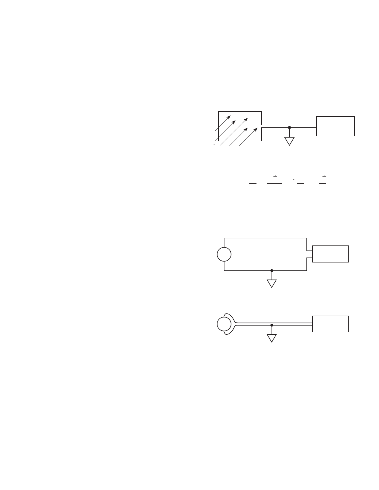
Operation
Sometimes, cooling the source is the only practical
method available to reduce noise. Again, however, the
available reduction is not as large as it might seem
because the reduction is related to the square root of the
change in temperature. For example, to cut the noise in
half, the temperature must be decreased from 293K to
73.25K, a four-fold decrease.
The most common method for noise reduction is to reduce
bandwidth with filtering. However, there is a tradeoff
between noise reduction and response time.
3.4.3 Magnetic fields
When the magnetic flux through a loop changes, a magnetic emf is created. This phenomenon will frequently
cause unwanted signals to occur in the test leads of a test
system. If the conductor has sufficient length or cross-sectional area, even weak magnetic fields such as those of the
earth can create sufficient signals to affect low-level measurements.
generate substantial magnetic fields, so care must be taken
to keep the Model 1801, signal source, and connecting
cables a good distance away from these potential noise
sources. Using twisted-pair input leads will also help to
reduce magnetically induced voltages.
Area A
(enclosed)
Nanovolt
B
The voltage developed due to a field passing
through a circuit enclosing a prescribed area is:
VB =
dφdtd (BA)
= = B + A
dt
dA
dt
Preamplifier
dB
dt
Figure 3-8
Magnetic field generation
As shown in Figure 3-8, generated magnetic fields are
determined by the loop area A, the magnetic flux B, as
well as the rates of change of these two parameters (dA/dt
and dB/dt). Thus, three ways to reduce these effects are:
(1) reduce the lengths of the connecting cables, (2) minimize the exposed circuit area, and (3) keep test leads and
magnetic field sources stationary. As shown in Figure
3-9a, a large loop area generates a relativ ely large v oltage,
while a small loop area shown in Figure 3-9b minimizes
the amount of voltage generated.
In extreme cases, magnetic shielding may be required.
Special metal with high permeability at low flux densities
(such as mu metal) are effectiv e at reducing these ef fects.
Even when the conductor is stationary, magnetically
induced signals may still be a problem. Fields can be produced by various sources such as the AC power line current. Large inductors such as power transformers can
Source
Nanovolt
Preamplifier
a. Large loop results in larger error voltage
Source
Nanovolt
Preamplifier
b. Small loop reduces error voltage
Figure 3-9
Minimizing interference from magnetic loops
3-21
Page 45

Operation
3.4.4 Electromagnetic interference (EMI)
The electromagnetic interference characteristics of the
Model 1801 Nanovolt Preamp comply with the electromagnetic compatibility (EMC) requirements of the
European Union (EU) directives as denoted by the CE
mark. Howev er, it is still possible for sensitive measurements to be affected by external sources. In these
instances, special precautions may be required in the test
setup.
Sources of EMI include:
• Radio and TV broadcast transmitters.
• Communications transmitters, including cellular
phones and handheld radios.
• Devices incorporating microprocessors and highspeed digital circuits.
• Impulse sources as in the case of arcing in highvoltage environments.
The Model 1801, signal source, and signal leads should be
kept as far away as possible from an y EMI sources. Additional shielding of the instrument, signal leads, sources,
and other measuring instruments will often reduce EMI to
an acceptable level. In extreme cases, a specially constructed screen room may be required to sufficiently attenuate the troublesome signal.
The Model 1801 filters may help to reduce EMI effects in
some situations. In other cases, additional external filtering may be required. Keep in mind, howe ver, that filtering
may have detrimental effects, such as increased settling
time, on the measurement.
with more than one signal return path such as power line
ground. As shown in Figure 3-10, the resulting ground
loop causes current to flow through the instrument LO
signal leads and then back through power line ground.
This circulating current develops a small, but undesirable
voltage between the LO terminals of the two instruments.
This voltage will be added to the source voltage, af fecting
the accuracy of the measurement.
Figure 3-11 shows how to connect instruments together to
eliminate this type of ground loop problem. Here, the circuit is grounded only at one point in the system. Although
some common-mode current still flows through the common-mode impedance Z
(typically nA or less), and the generated error voltage is
insignificant compared to the source voltage.
Ground loops are not normally a problem with instruments like the Model 1801 that have low common-mode
current. Howev er, all instruments in the test setup may not
be designed in this manner. When in doubt, consult the
manual for all instrumentation in the test setup.
, that current is very small
CM
3.4.6 Shielding
Proper shielding of all signal paths and sources being
measured is important to minimize noise pickup in virtually any low-level measurement situation. Otherwise,
interference from such noise sources as line frequency
and RF fields can seriously corrupt measurements, compromising the validity of experimental data.
3.4.5 Ground loops
When two or more instruments are connected together,
care must be taken to avoid unwanted signals caused by
ground loops. Ground loops usually occur when sensitive
instrumentation is connected to other instrumentation
3-22
In order to minimize noise, a closed metal shield, completely surrounding the source, is recommended. This
shield should be connected to input LO, and LO may also
have to be connected to chassis ground. Some experimentation may be required to determine which of the two connecting methods provides the best results.
Page 46

Experiment
(source)
Operation
HI
Preamplifier
E
S
R
E
IN
LO
Ground 1
Figure 3-10
Power line ground loops
I
Ground bus
V
G
Input voltage to the preamplifier is:
= ES + I R
E
IN
Resistance of input LO connection
(typically around 100mΩ)
Current passing through input LO
connection due to ground voltages
) in the ground bus (magnitude
(V
G
may be amperes).
Source voltage (desired signal)
IR may exceed
≈ IR.
E
IN
by orders of magnitude.
ES
Ground 2
3-23
Page 47

Operation
Experiment
(source)
E
S
R
I
Z
CM
Ground bus
V
G
Input voltage to the preamplifier is:
E
= ES + I R
IN
Resistance of input LO connection
(typically around 100mΩ)
E
IN
HI
Preamplifier
LO
Single
System
Ground
Figure 3-11
Eliminating ground loops
Current passing through Z
GΩ) due to V
and currents in the
G
CM
source (magnitude is typically
hundreds of nA’s).
Source voltage (desired signal)
E
≈ ES, since IR is now insignificant compared to ES.
IN
(MΩ or
3-24
Page 48

4
Performance Verification
4.1 Introduction
The procedures in this section are intended to verify that
Model 1801 accuracy is within the limits stated in the
preamplifier one-year specifications (see Appendix A).
These procedures can be performed when the unit is first
received to ensure that no damage or misadjustment has
occurred during shipment. Verification may also be performed whenever there is a question of preamplifier accuracy, or following calibration, if desired.
WARNING
The procedures in this section are intended only for qualified service personnel. Do not attempt to perform
these procedures unless you are qualified to do so.
NOTE
If the preamplifier is still under warranty, and its performance is outside specified limits, contact your Keithley
representative or the factory to determine the correct course of action.
This section includes the following:
4.2 Environmental conditions: Covers the tempera-
ture and humidity limits for verification.
4.3 Warm-up period: Describes the length of time the
Model 1801 should be allowed to warm up before
testing.
4.4 Line power: Covers power line voltage ranges dur-
ing testing.
4.5 Recommended equipment: Summarizes recom-
mended equipment and pertinent specifications.
4.6 Verification limits: Explains how reading limits
were calculated.
4.7 Restoring factory default conditions: Gives step-
by-step procedures for restoring default conditions
before each test procedure.
4.8 Verification procedures: Details procedures to ver-
ify measurement accuracy of Model 1801 measurement functions.
4.2 Environmental conditions
DC voltage verification measurements must be made at an
ambient temperature of 23 ±1°C, and at a relativ e humidity of less than 80%. (Although the Model 1801 could
normally be tested at 23 ±5°C, the low-thermal voltage
divider used for DCV verification must be operated at 23
±1°C to meet its stated specifications.) AC voltage verification measurements must be made at an ambient temperature of 23 ±5°C, and at a relative humidity of less than
80%.
4-1
Page 49

Performance Verification
4.3 Warm-up period
The Model 1801 must be allowed to warm up for at least
two hours before performing the verification procedures.
If the preamplifier has been subjected to temperature
extremes (outside the range stated in paragraph 4.2),
allow additional time for internal temperatures to stabilize. Typically, it takes one additional hour to stabilize a
unit that is 10°C (18°F) outside the specified temperature
range.
The test equipment should also be allowed to warm up for
the minimum period specified by the manufacturer.
4.4 Line power
The Model 1801 should be tested with the Model 2001
operating from a line voltage in the range of 90-134V or
180-250V at a frequency of 50, 60, or 400Hz.
4.5 Recommended test equipment
T able 4-1 lists all test equipment required for v erification.
Alternate equipment may be used as long as that equip-
ment has specifications at least as good as those listed in
the table.
4.6 Verification limits
The verification limits stated in this section have been
calculated using only Model 1801 one year specifications,
and they do not include test equipment tolerance. If a
particular measurement falls slightly outside the allowed
range, recalculate new limits based both on Model 1801
specifications and pertinent calibration equipment
specifications. For DC volts verification, additional
uncertainty includes both calibrator and low-thermal
divider uncertainty.
NOTE
Model 1801 verification procedures
assume that the Model 2001 Multimeter
is properly calibrated and meets its
stated specifications. See the Model
2001 Calibration Manual for performance verification procedures and calibration information.
Table 4-1
Recommended test equipment for performance verification
Manufacturer Model Description Specifications*
Fluke 5700A Calibrator DCV: 0.19V, ±11ppm
ACV: 450µV, 100Hz:±1.03%
2
Keithley 262 Low-thermal voltage divider 10
Keithley 1507 Low-thermal input cable
* 90-day calibrator specifications shown include total uncertainty at specified output. Low-thermal divider specifications
are for one year.
to 1 : ±35ppm
3
10
to 1 : ±35ppm
4
10
to 1 : ±100ppm
4-2
Page 50

Performance Verification
4.7 Restoring default conditions
Before performing each performance verification procedure, restore Model 1801 default conditions as follows:
1. From the normal display mode, press the MENU k e y .
The Model 2001 will display the following:
MAIN MENU
SAVESETUP GPIB CALIBRATION
2. Select SAVESETUP, and press ENTER. The following will be displayed:
SETUP MENU
SAVE RESTORE POWERON RESET
3. Select RESET, and press ENTER. The display will
then appear as follows:
RESET ORIGINAL DFLTS
BENCH GPIB
4. Select BENCH, then press ENTER. The following
will be displayed:
If the Model 1801 is out of specifications and not under
warranty , refer to the calibration procedures in Section 5.
WARNING
The maximum common-mode voltage
(voltage between INPUT LO and
chassis ground) is 41V peak. Exceeding this value may cause a breakdown
in insulation, creating a shock hazard.
4.8.1 DC volts verification
DC voltage accuracy is verified by applying accurate DC
voltages from a calibrator and low-thermal voltage
divider to the Model 2001 input and verifying that the displayed readings fall within specified ranges.
Follow the steps below to verify DCV measurement
accuracy.
RESETTING INSTRUMENT
ENTER to conÞrm; EXIT to abort
5. Press ENTER again to confirm instrument reset. The
instrument will return to normal display, and the
Model 1801 will be enabled.
4.8 Verification procedures
The following paragraphs contain procedures for verifying preamplifier accuracy specifications for the following
measuring functions:
• DC volts
• AC volts
Note that frequency accuracy is a function of the Model
2001 Multimeter and can be verified using the procedure
in the Model 2001 Calibration Manual. Temperature
accuracy is automatically confirmed by verifying the
accuracy of the 2mV DC range, which is used for temperature measurements.
CAUTION
Do not exceed 1V peak between
INPUT HI and INPUT LO, or preamplifier damage may occur. (Inputs
over 2mV will require a one-minute
recovery period.)
1. Connect the DC calibrator and Model 262 Lowthermal Voltage Divider to the Model 1801 input, as
shown in Figure 4-1.
NOTE
Use only shielded, low-thermal cable
between the low-thermal divider and the
Model 1801 input terminals.
2. Turn on the Model 2001 and the calibrator, and allow
a two-hour warm-up period before making
measurements.
3. Restore Model 1801 factory default conditions, as
explained in paragraph 4.7.
4. Select the Model 1801 20µV DC range.
4-3
Page 51

Performance Verification
262 Low-thermal
Voltage Divider
Sense HI
5700A Calibrator (Output DC Volts)
Output
Sense
HI LO
Input
1507 Low-thermal Cable
Input HI
Output HI
Output LO
Sense LO
KEITHLEY
INPUTS
HI
PEAK
LO
PEAK
1801 NANOVOLT PREAMP
2mV
41V
a. Input Connections
NOTE : Put calibrator in external sense mode, and
use 2.2V range.
V ZERO
I ZERO
!
Input LO
CAUTION:
NO INTERNAL OPERATOR SERVICEABLE PARTS,
SERVICE BY QUALIFIED PERSONNEL ONLY.
HI (Red)
Figure 4-1
Connections for DC volts verification
LO (Black)
b. Output Connections
4-4
Page 52

Performance Verification
5. Select the SLOW response filter as follows:
A. Press the CHAN key. The instrument will display
the following:
CONFIG PREAMP
CONTROL FILTER CALIBRATION
B. Select FILTER, then press ENTER. The unit will
display filter response selections:
SELECT PREAMP FILTER
FAST MEDIUM SLOW
C. Select the SLOW filter response, then press
ENTER.
D. Press EXIT to return to normal display.
6. Set the low-thermal divider division ratio to 10
select the POS+ polarity position.
Table 4-2
Limits for DC volts verification
4
, and
7. Lock the calibrator on the 2.2V range, and enable
external sensing.
8. Set the calibrator output to 0.00000VDC, and allow
the reading to settle.
9. Enable the Model 2001 REL mode.
10. Set the calibrator output to +0.190000VDC, and
allow the reading to settle.
11. Verify that the Model 2001 reading is within the limits summarized in Table 4-2.
12. Repeat steps 8 through 11 for the remaining ranges,
voltages, and divider ratios listed in Table 4-2. Be
sure to re-zero each range before making the
measurement.
13. Repeat the procedure for each of the ranges with negative Model 1801 input voltages of the same magnitude as those listed in Table 4-2. Set the divider to the
NEG- polarity position to reverse polarity.
Calibrator
1801 range
20µV
200µV
2mV
Notes:
1. Repeat procedure for negative voltages.
2. Reading limits do not include calibrator and low-thermal divider uncertainty.
voltage
0.190000V
0.190000V
0.190000V
Low-thermal
divider ratio
4
10
: 1
3
10
: 1
2
10
: 1
1801 input
voltage Allowable readings (1 year, 23 ±1°C)
19.00000µV
190.0000µV
1.900000mV
18.99006µV to 19.00994µV
189.9466µV to 190.0534µV
1.899494mV to 1.900506mV
4-5
Page 53

Performance Verification
4.8.2 AC volts verification
AC voltage accuracy is checked by applying an accurate
AC voltage at 100Hz from an AC calibration source and
then verifying that the Model 1801 AC voltage reading
falls within the specified range.
CAUTION
Do not exceed 1V peak between INPUT HI and INPUT LO, or preamplifier damage may occur. (Inputs over
2mV peak will require a one-minute
recovery period.)
1. Turn on the Model 2001 and calibrator, and allow a
two-hour warm-up period before making
measurements.
2. Connect the calibrator to the Model 1801 input, as
shown in Figure 4-2.
3. Restore Model 1801 factory default conditions, as
explained in paragraph 4.7.
4. Select the AC + DC coupling mode as follows:
A. Press CONFIG ACV, select COUPLING, then
press ENTER.
B. Select AC+DC, then press ENTER.
C. Press EXIT to return to normal display.
5. Select the ACV function, and make sure that REL is
disabled.
NOTE
Do not use REL to null offsets when performing AC volts tests.
6. Set the calibrator output to 450.000µV AC RMS at a
frequency of 100Hz, and allow the reading to settle.
7. Verify that the Model 2001 reading is within the limits summarized in Table 4-3.
Table 4-3
Limits for AC voltage verification
1801
range
500µV 450.000µV RMS
Note: Limits shown do not include calibrator uncertainty.
Calibrator
voltage
@ 100Hz
Allowable readings
(1 year, 23 ±5°C)
422.500µV to
477.500µV
4.8.3 Resistance verification
Model 1801 resistance accuracy specifications are deriv ed
from Model 2001 current source accuracy as well as
Model 1801 DC volts measurement accuracy. As long as
the Model 2001 ohms and DC volts functions, and the
Model 1801 DC volts function meet their respectiv e accuracy specifications, preamplifier ohms function accuracy
is automatically verifie, and it is not necessary to separately verify measurement accuracy of the Model 1801
ohms function. See the Model 2001 Calibration Manual
for multimeter verification procedures.
4-6
Page 54

Output HI
Output LO
5700A Calibrator (Output DC Volts)
Performance Verification
Supplied Low-thermal Cable
HI (Red)
Input HI
KEITHLEY
INPUTS
HI
2mV
PEAK
LO
41V
PEAK
1801 NANOVOLT PREAMP
a. Input Connections
Input LO
V ZERO
I ZERO
CAUTION:
NO INTERNAL OPERATOR SERVICEABLE PARTS,
SERVICE BY QUALIFIED PERSONNEL ONLY.
!
Figure 4-2
Connections for AC volts verification
LO (Black)
b. Output Connections
4-7
Page 55

5
Service Information
5.1 Introduction
This section contains information necessary to service the
Model 1801 Nanovolt Preamplifier.
WARNING
The information in this section is
intended only for qualified service
personnel. Do not attempt these procedures unless you are qualified to do
so.
Information is arranged as follows:
5.2 Calibration: Covers the equipment and procedures
necessary to calibrate the Model 1801.
5.3 Principles of operation: Briefly discusses circuit
operation.
5.4 Special handling of static-sensitive devices:
Reviews precautions necessary when handling
static-sensitive devices.
• Normal calibration, where the Model 1801 preamplifier, power supply card, and Model 2001 are calibrated together as a unit. The normal calibration
method should be used in most cases.
• Gain constants calibration, where preamplifier gain
constants are manually entered into the Model 2001.
This method can be used to transfer gain constants
from one power supply card to another when a
preamplifier module is to be used with a power
supply card other than the one with which it was
calibrated.
5.2.1 Environmental conditions
Normal calibration procedures should be performed at an
ambient temperature of 23° ±1°C, and at a relativ e humidity of less than 80% unless otherwise noted.
5.5 Troubleshooting: Presents some troubleshooting
tips for the Model 1801.
5.2 Calibration
This section gives detailed procedures for calibrating the
Model 1801. Basically, there are two types of calibration
procedures:
5.2.2 Warm-up period
The Model 1801 must be allowed to warm up for at least
two hours before calibration. If the preamplifier has been
subjected to temperature extremes (outside the range
stated in paragraph 5.2.1), allow additional time for internal temperatures to stabilize. Typically, it takes one additional hour to stabilize a unit that is 10°C (18°F) outside
the specified temperature range.
5-1
Page 56

Service Information
Ω
The calibration equipment should also be allowed to
warm up for the minimum period specified by the
manufacturer.
5.2.3 Line power
The Model 1801 should be calibrated while the Model
2001 is operating from a line voltage in the range of
90-134V or 180-250V at 50, 60, or 400Hz.
5.2.4 Recommended calibration equipment
Table 5-1 lists all test equipment recommended for calibration. Alternate equipment may be used as long as that
equipment has specifications at least as good as those
listed in the table.
5.2.5 Offset adjustments
The following procedure to null offsets must be performed before performing the normal calibration procedure covered in paragraph 5.2.6. The basic procedure for
nulling offsets is as follows:
1. Clean the input terminals, then connect the lowthermal shorting strap to the INPUTS terminals, as
shown in Figure 5-1. Note that Figure 5-1 also shows
the location of the voltage offset control (V ZERO).
2. Make certain the preamplifier module is installed in
the thermal isolation enclosure. Remove the lid only
while making adjustments.
3. Turn on the Model 2001 power, and make sure the
preamplifier is enabled as follows:
A. Press the CHAN key.
B. Select CONTROL, then press ENTER.
C. Select ENABLE, then press ENTER.
4. Select the 20µV DC range, and allow a two-hour
warm-up period before proceeding with the offset
adjustments.
5. Select the slow response filter as follows:
A. Press CHAN.
B. Select FILTER, then press ENTER.
C. Select SLOW, then press ENTER.
D. Press EXIT to return to normal display.
6. Adjust the voltage offset control (V ZERO) for a
Model 2001 front panel reading of 0µV ± 0.001µV.
7. Enable the REL mode to null any remaining offset.
8. Disconnect the low-thermal shorting strap from the
INPUTS terminals, and connect the 10k
lowthermal resistor to the INPUTS terminals, as shown
in Figure 5-2. (For best results, remove the lead
plating before use.) Note that the offset current
adjustment control (I ZERO) is also shown in Figure
5-2.
5-2
Table 5-1
Recommended equipment for calibration
Mfg. Model Description Specifications*
Fluke 5700A Calibrator 0.2V DC: ±11ppm
2
Keithley 262 Low-thermal Voltage Divider 10
: 1, ±35ppm
3
10
: 1, ±35ppm
4
10
: 1, ±100ppm
Keithley 1507 Low-thermal Cable
Keithley Low-thermal Shorting Strap**
Keithley Part # R-336-10K Low-thermal Resistor*** 10kΩ, ±5%
* 90-day calibrator specifications shown include total uncertainty at specified output. Model 262 specifications are for
one year.
** Low-thermal shorting strap is supplied with the Model 1801.
***Remove plating from leads before use.
Page 57

Service Information
Offset Voltage Adjustment
KEITHLEY
INPUTS
HI
2mV
PEAK
LO
41V
PEAK
Low-thermal
Shorting Strap
Figure 5-1
Connections for offset voltage adjustment
KEITHLEY
INPUTS
HI
2mV
PEAK
LO
41V
PEAK
1801 NANOVOLT PREAMP
V ZERO
I ZERO
CAUTION:
NO INTERNAL OPERATOR SERVICEABLE PARTS,
SERVICE BY QUALIFIED PERSONNEL ONLY.
!
1801 NANOVOLT PREAMP
V ZERO
I ZERO
CAUTION:
NO INTERNAL OPERATOR SERVICEABLE PARTS,
SERVICE BY QUALIFIED PERSONNEL ONLY.
!
10kΩ
Low-thermal
Resistor
Offset Voltage Adjustment
Figure 5-2
Connections for offset current adjustment
9. Make sure that the thermal isolation enclosure lid is
in place, and allow two minutes for thermals to settle.
10. Adjust the current offset control (I ZERO) for a
Model 2001 front panel reading of 0µV ± 0.1µV
11. Disconnect the low-thermal resistor when the offset
adjustment is complete.
5-3
Page 58

Service Information
5.2.6 Normal calibration
The normal calibration procedure calibrates the preamplifier module and its power supply card as a unit. Since the
constants derived during the calibration process are stored
in NVRAM located on the power supply card, the preamplifier module should normally be used with the power
supply card that was used during calibration. (To interchange preamp modules and power supply cards without
recalibration, use the gain constants calibration method
discussed in paragraph 5.2.7.)
Normal calibration should be performed at least once a
year, or e very 90 days to ensure the Model 1801 meets the
corresponding specifications.
NOTE
Proper calibration of the Model 1801
requires that the Model 2001 Multimeter
meets its stated specifications. See the
Model 2001 Calibration Manual for
information on performance verification
and calibration procedures for the
Model 2001.
The offset adjustments explained in
paragraph 5.2.5 must be performed
before calibrating the preamplifier.
6. Press the Model 2001 CHAN k ey, the instrument will
display the following:
CONFIGURE PREAMP
CONTROL FILTER CALIBRATION
7. Select CALIBRATION, then press ENTER. The
Model 2001 will then display the following:
PREAMP CAL MENU
CALIBRATION-DATES CALIBRATE
8. Select CALIBRATE, then press ENTER. The instrument will then prompt you to complete the precal
(offset adjustment) procedure before continuing:
PRECAL step must be
done before proceeding.
See paragraph 5.2.5 for details on performing the offset adjustment procedure.
9. Press ENTER, and note that the instrument prompts
you to set the calibrator output to 0V:
Set calibrator to 0V
Front panel calibration procedure
Follow the steps below to calibrate the Model 1801 from
the front panel:
1. Make sure the Model 1801 is properly installed and
enabled, as explained in Sections 2 and 3 of this
manual.
2. Connect the Model 1801, DC calibrator, and lowthermal voltage divider, as shown in Figure 5-3. Be
sure that the preamplifier module is installed in the
thermal isolation enclosure, and that the lid is firmly
in place.
3. Turn on the Model 2001 and the calibrator, and allow
a two-hour warm-up period before continuing with
calibration.
4. Set the calibrator to the e xternal sense mode, and lock
the unit on the 2.2V range.
5. Set the Model 262 polarity switch to the POS+
position.
Set the calibrator output to 0.0000V DC, put the unit
in operate, then press ENTER on the Model 2001.
10. The Model 2001 will then prompt you to set the
divider ratio of the Model 262 to 10
2
as follows:
Set 262 to 10^2
Set the Model 262 divider ratio to 10
position. Wait two minutes for thermal EMFs to settle, then press ENTER to continue.
11. Next, the instrument will prompt you to set the
divider ratio to 10
3
.
2
and the +POS
Set 262 to 10^3
Set the Model 262 divider ratio to 10
ENTER.
3
, then press
5-4
Page 59

Service Information
12. The unit will then prompt for a 10
follows:
Set 262 to 10^4
Set the Model 262 divider ratio to 10
ENTER.
262 Low-thermal
Voltage Divider
Output
1507 Low-thermal Cable
Sense
HI LO
Input
4
divider ratio as
4
, then press
Sense HI
Output HI
Output LO
KEITHLEY
INPUTS
HI
2mV
PEAK
LO
41V
PEAK
13. Next, the Model 2001 will prompt you to set the DC
calibrator output voltage to 200mV as follows:
Calibrator to 200 mV
Set the calibrator output to 0.20000V DC.
5700A Calibrator (Output DC Volts)
NOTE : Put calibrator in external sense mode, and
use 2.2V range.
Sense LO
1801 NANOVOLT PREAMP
V ZERO
I ZERO
CAUTION:
NO INTERNAL OPERATOR SERVICEABLE PARTS,
SERVICE BY QUALIFIED PERSONNEL ONLY.
!
Figure 5-3
Calibration connections
a. Input Connections
Input HI
Input LO
HI (Red)
LO (Black)
b. Output Connections
5-5
Page 60

Service Information
14. The Model 2001 will then display the precise calibration voltage:
Cal: 200.00000 mVDC
15. Make sure that the divider ratio is still set to 10
you are using the recommended 200mV calibration
voltage setting, simply press ENTER at this point.
Otherwise, set the displayed value to the exact calibration voltage, then press ENTER. (Note: 200mV is
recommended for most accurate results.)
16. Next, the unit will prompt you to set the divider ratio
3
to 10
as follows:
4
. If
Set 262 to 10^3
Set the Model 262 divider ratio to 10
ENTER.
17. You will then be prompted to set the divider ratio to
2
10
:
3
, then press
21. Press ENTER to complete calibration and save new
calibration constants. If you wish to abort the process
without saving calibration constants, press EXIT
instead.
22. Press EXIT to return to normal display.
NOTE
If an error occurs, an appropriate error
message will be displayed. See the discussion below on error messages.
IEEE-488 bus calibration procedure
Follow the steps below to calibrate the Model 1801 over
the IEEE bus. Table 5-2 lists IEEE-488 bus calibration
commands, and Table 5-3 summarizes the bus calibration
procedure. (See Appendix B for calibration program listings.) Note that commands must be sent in the order indicated in Table 5-3. To abort the calibration procedure,
send :CAL:UNPR:PRE:ABOR.
Set 262 to 10^2.
Set the divider ratio to 10
18. Next the instrument will prompt you for the calibration date:
2
, then press ENTER.
CAL DATE: 01/01/93
Change the date as required, then press ENTER.
19. The multimeter will then prompt for the calibration
due date:
NEXT CAL: 01/01/94
Change the calibration due date as required, then
press ENTER.
20. Finally, the unit will indicate that preamplifier calibration is completed:
PREAMP Cal complete
Procedure
1. Make sure the Model 1801 is properly installed, as
explained in Sections 2 and 3 of this manual.
NOTE
The offset adjustments explained in
paragraph 5.2.5 must be performed
before calibrating the Model 1801.
2. Connect the Model 1801, DC calibrator, and lowthermal voltage divider, as shown in Figure 5-3. Be
sure that the preamplifier module is installed in the
thermal isolation enclosure, and that the lid is firmly
in place.
3. Connect the Model 2001 IEEE-488 bus of the controller you intend to use to send calibration commands to the instrument. Use a shielded IEEE-488
connecting cable to minimize noise.
4. Turn on the Model 2001 and the calibrator, and allow
a two-hour warm-up period before continuing with
calibration.
5-6
Page 61

Table 5-2
Model 1801 IEEE-488 bus calibration commands
Command Description
Service Information
:CALibration
:UNPRotected
:PREamp
:G1K <value>
:G1K?
:G10K <value>
:G10K?
:G100K <value>
:G100K?
:Z1K
:Z10K
:Z100K
:FS1K <value>
:FS10K <value>
:FS100K <value>
:DATE Ò<string>Ó
:DATE?
:NDUE Ò<string>Ó
:NDUE?
:CALCulate
Calibration root command.
Commands not protected by CAL switch.
Preamp commands.
Directly enter 2mV gain (min = 0.5; max = 1.5; default = 1.0).
Request 2mV gain constant.
Directly enter 200µV gain (min = 0.5; max = 1.5; default = 1.0).
Request 200µV gain constant.
Directly enter 20µV gain (min = 0.5; max = 1.5; default = 1.0).
Request 20µV gain constant.
Measure 2mV range zero.
Measure 200µV range zero.
Measure 20µV range zero.
Measure 2mV range full-scale <value>= 1E-3 to 2E-3.
Measure 200µV range full- scale. <value> = 100E-6 to 200E-6.
Measure 20µV range full- scale. <value > = 10E-6 to 20E-6.
Send calibration date.
Request calibration date.
Send calibration due date.
Request calibration due date.
Calculate calibration constants, test if they are valid (valid
range = 0.98 to 1.2).
:SAVE
:ABORt
Notes:
1. Upper-case letters indicate command short form. For example, instead of sending “:CALIBRATION:UNPROTECTED:
PREAMP:CALCULATE,” you can send “:CAL:UNPR:PRE:CALC.”
2. Angle brackets (<>) indicate command parameters and should not be included in the command.
3. Preamplifier calibration constants are stored in NVRAM located on the power supply card.
Save calibration constants in NVRAM.
Abort calibration procedure.
Table 5-3
IEEE-488 bus calibration summary
Calibrator
Order*
1
2
3
4
5
6
7
voltage
0.0000V
0.0000V
0.0000V
0.200000V
0.200000V
0.200000V
-
-
-
-
* Commands must be sent in order shown.
Divider
ratio Calibration command
2
10
3
10
4
10
4
10
3
10
2
10
-
-
-
-
:CAL:UNPR:PRE:Z1K
:CAL:UNPR:PRE:Z10K
:CAL:UNPR:PRE:Z100K
:CAL:UNPR:PRE:FS100K 20E-6
:CAL:UNPR:PRE:FS10K 200E-6
:CAL:UNPR:PRE:FS1K 2E-3
:CAL:UNPR:PRE:CALC
:CAL:UNPR:PRE:DATE ‘<cal_date>’
:CAL:UNPR:PRE:NDUE ‘<due_date>’
:CAL:UNPR:PRE:SAVE
5-7
Page 62

Service Information
5. Use the GPIB MENU to set the Model 2001 primary
address to the value used in the controller program
(default = 16).
6. Set the calibrator to the e xternal sense mode, and lock
the unit on the 2.2V range.
7. Set the Model 262 polarity switch to the POS+ position, and set the low-thermal divider ratio to 10
2
.
8. Set the calibrator output to 0.0000V DC, put the unit
in operate, then wait two minutes for thermal EMFs
to settle before continuing.
9. Send the following command strings over the bus:
:INP:PRE:STAT ON
:CAL:UNPR:PRE:Z1K
Wait until the instrument completes this step before
going on.
10. Set the Model 262 divider ratio to 10
11. Send the following command string over the bus:
3
.
17. Set the Model 262 divider ratio to 10
3
, then press
ENTER.
18. Send the following command string over the bus:
:CAL:UNPR:PRE:FS10K 200E-6
Be sure to use the exact calibration value if you are
using a voltage other than 200µV. The allowable
range is from 100µV to 200µV (100E-6 to 200E-6).
Wait until the unit completes this step before
continuing.
19. Set the Model 262 divider ratio to 10
2
.
20. Send the following command string over the bus:
:CAL:UNPR:PRE:FS1K 2E-3
Be sure to use the exact calibration value if you are
using a voltage other than 2mV. The allowable range
is from 1mV to 2mV (1E-3 to 2E-3). Wait until the
unit completes this step before continuing.
:CAL:UNPR:PRE:Z10K
Wait until the unit completes this step before
continuing.
12. Set the Model 262 divider ratio to 10
4
.
13. Send the following command string over the bus:
:CAL:UNPR:PRE:Z100K
Wait until the unit finishes this step before
proceeding.
14. Set the calibrator output voltage to 0.20000V DC.
15. Make sure that the divider ratio is still set to 10
4
.
16. Send the following command string over the bus:
:CAL:UNPR:PRE:FS100K 20E-6
Be sure to use the exact calibration value if you are
using a voltage other than 20µV (input voltage = calibrator voltage/divider ratio). The allowable range is
from 10µV to 20µV (10E-6 to 20E-6).
Wait until the unit completes this step before
continuing.
21. Send the following command over the bus:
:CAL:UNPR:PRE:CALC
Wait until the unit completes this step before
continuing.
22. Send the following commands to program calibration
date and next due date:
:CAL:UNPR:PRE:DATE Ô01/01/93Õ
:CAL:UNPR:PRE:NDUE Ô01/01/94Õ
(Substitute the appropriate dates for those in the
above examples.)
23. Send the following command to save calibration
constants:
:CAL:UNPR:PRE:SAVE
NOTE
An error message will be generated if a
calibration error occurs. See the discussion below on error messages.
5-8
Page 63

Service Information
×
×
×
■
×
Calibration errors
One of the errors listed in Table 5-4 may occur during the
course of calibration. (These errors will appear on the
front panel and may be obtained over the bus by using the
:SYST:ERR? query.) The most likely causes of these
errors are:
• Incorrect connections.
• Wrong calibrator voltage setting.
• Improper low-thermal divider setting.
Table 5-4
Preamplifier calibration errors
Error ID code Error message
+445
+446
+447
Viewing and changing calibration dates
Preamplifier calibration dates can be viewed or changed
by using the CALIBRATION-DATES selection in the
PREAMP CAL MENU. To change dates, simply follow
the prompts on the display.
Preamp 1k gain out of spec
Preamp 10k gain out of spec
Preamp 100k gain out of spec
supply card. The basic procedures for reading and storing
constants are explained in the following paragraphs.
Reading gain constants
There are three gain constants that are derived during nor mal calibration:
• G1K:
• G10K:
• G100K:
These constants can be read from the front panel or over
bus, as outlined below.
Reading Constants from the Front Panel
To read gain constants from the front panel, select
ENTER-CAL-CONSTANTS in the PREAMP CAL
MENU, then press ENTER. Select the desired constant to
display , then press ENTER. The unit will then display the
present value of the constant. For example, the
gain constant may appear as follows:
1,000 gain constant
10,000 gain constant
100,000 gain constant
1,000
G1k = 1.0000000
Repeat the process for the other two constants, and record
their values for storage in the other power supply card.
5.2.7 Gain constants calibration
The gain constants method of calibration provides a
simple method of transferring the calibration constants
stored in one power supply card to a different power
supply card. This feature is useful in situations where a
preamplifier module is to be used with a power supply
card other than the one with which it was originally
calibrated, and it eliminates having to perform normal
calibration whenever a preamplifier module is moved
from one power supply card to another.
To use this method, first read the gain constants from the
power supply card originally used when calibrating the
preamplifier, then store the constants in the new power
■ Reading Constants Over the IEEE-488 Bus
To read constants over the bus, first send the appropriate
query:
:CAL:UNPR:PRE:G1K? (×1,000 gain constant)
:CAL:UNPR:PRE:G10K? (
:CAL:UNPR:PRE:G100K? (
After sending the query, address the instrument to talk in
the usual manner, then input the constant into a convenient floating-point numeric variable. Constants are
returned in standard floating-point format.
×10,000 gain constant)
×100,000 gain constant)
5-9
Page 64

Service Information
Storing constants
Calibration constants can be stored from the front panel or
over the bus, as explained below. The nominal (ideal)
value for each of these constants is 1.0. The allowable
range is from 0.5 to 1.5; if you attempt to enter a value
outside this range, a “Parameter data out of range” error
will occur.
■ Storing Constants from the Front Panel
To enter gain constants from the front panel, select
ENTER-CAL-CONSTANTS in the PREAMP CAL
MENU, then press ENTER. Select the desired constant to
display , then press ENTER. The unit will then display the
present value of the constant. Use the range and cursor
keys to enter the constant value, then press ENTER to
complete the process. Repeat the procedure for the other
two constants.
NOTE
NOTE
Programmed constants are only temporary and will be lost when power is
cycled unless the :CAL:UNPR:PRE:
SAVE command is sent to permanently
save them.
5.3 Principles of operation
The following paragraphs discuss the basic operating
principles for the Model 1801, and can be used as an aid
in troubleshooting the preamplifier. Refer to drawing
number 1801-106, located at the end of Section 6, for a
schematic diagram of the power supply card.
5.3.1 Block diagram
Figure 5-4 shows a simplified block diagram of the Model
1801. The unit includes a remote preamplifier, a power
supply connecting cable, and a power supply card. Each
of these components is briefly discussed below.
Constants entered from the front panel
are only temporary and will be lost when
power is cycled. In order to save constants permanently , you must use the bus
:CAL:UNPR:PRE:SAVE command, as
explained below.
■ Storing Constants Over the IEEE-488 Bus
To write constants over the bus, send the appropriate
command along with the corresponding numeric constant
value:
:CAL:UNPR:PRE:G1K <value> (×1,000 gain constant)
:CAL:UNPR:PRE:G10K <value> (
:CAL:UNPR:PRE:G100K <value> (
Here <value> represents the constant value in floatingpoint numeric format.
×10,000 gain constant)
×100,000 gain constant)
5.3.2 Preamplifier module
The remote preamplifier uses a chopper demodulator system. With this topology, the input signal is chopped at a
frequency of 288Hz, and it is then magnetically amplified.
A narrow-band AC amplifier follows the magnetic components. The signal is then demodulated and amplified,
and the resulting DC signal is then fed back to the input to
buck the input signal to maintain high input impedance
and low input bias current.
5.3.3 Power supply cable
The power supply cable carries the ±9V DC supplies and
gain/filter control lines from the power supply card to the
preamp module. It also carries the amplified output signal
back from the preamp module to the power supply card
where it is routed to the Model 2001 Multimeter.
5.3.4 Power supply card
T o permanently sa v e ne w gain constants, send the follo wing command after storing new constants:
:CAL:UNPR:PRE:SAVE
5-10
The power supply card is made up of three basic sections:
the preamplifier power supply, the common-mode rejection circuit and its power supply, and the control and
memory circuits. Each of these sections is briefly discussed below.
Page 65

2001 Power
Connector
To
2001
Gain/Filter
Switching
Memory
Common-Mode Current
Supply
#2
Preamp Power Supply
#1
Power Supply Card
Cancellation Circuit
Preamp/
Power
Supply
Cable
Service Information
LO
To 2001 Input
HI
Gain/Filter
Switching
X1k,
X10k, or
X100k
Gain
± 9V
Supplies
Preamp Module
Figure 5-4
Block diagram
Preamplifier power supply
The preamplifier power supply uses a linear, high-frequency, dual-transformer topology operating at a frequency of 4.8kHz. The two-transformer configuration
(T101 and T102) reduces the 4.8kHz common-mode current component, which is not fed through the commonmode cancellation circuit (described below). The switching frequency is generated by the 555 timer, U103. The
resulting 4.8kHz, 50% duty cycle signal is fed to the
switching MOSFETs (Q101 and Q103), which drive the
two transformers.
The 4.8kHz signal from the transformers is converted to
positive and negative DC voltages by two full-wave rectifiers (CR103). The DC voltages are then filtered by C104
and C105 and then regulated down to their final ±9V values by U104 and U105. Additional post-regulation filtering is provided by C102 and C103.
Inputs
(2mV max)
LO HI
Common-mode rejection circuit
The common-mode rejection circuit is made up of U107,
U108, and related components. This circuit senses the
common-mode current through R127, and it generates an
equal and opposite null current.
The common-mode rejection circuit has its own power
supply made up of CR102, U109, U110, and related components. CR102 rectifies the 4.8kHz input signal, while
U109 and U110 provide regulation down to the final
±5.2V values.
Memory and control circuits
U102, a non-volatile RAM (NVRAM), stores the
calibration constants for the preamplifier module. During
calibration, constants are stored in U102, and the Model
5-11
Page 66

Service Information
2001 reads these calibration constants from the device
during power-up. Note that data transmission is
performed serially.
The gain and filter control circuits include U101, U106,
A T101 through AT104, and associated components. Serial
control DATA from the Model 2001 is clocked into U101
with the aid of the CLK (clock) signal. Once all control
bits are shifted in, the STB (strobe) signal latches the control bits into the U101 outputs, and the control signals are
coupled through the four opto-isolators to the preamplifier module. U106 is a power-on hold-off circuit, which
inhibits random control information from being sent to
the preamplifier module when the instrument is first
turned on.
5.4 Special handling of static-sensitive devices
CMOS and other high-impedance devices are subject to
possible static discharge damage because of the highimpedance levels involved. When handling such devices,
use the precautions listed below.
NOTE
In order to prevent damage, assume that
all parts are static-sensitive.
5.5 Troubleshooting
5.5.1 Troubleshooting equipment
Table 5-5 summarizes recommended equipment for troubleshooting the Model 1801.
Table 5-5
Recommended troubleshooting equipment
Manufacturer
Description
Multimeter
Oscilloscope
5.5.2 Troubleshooting access
In order to gain access to the power supply card circuit
board to measure voltages under actual operation conditions, perform the following steps:
1. Turn off the Model 2001 power, and disconnect the
line cord and all other equipment.
2. Remove the Model 2001 cover.
3. Install the power supply card in the multimeter.
4. Connect the line cord, and turn on the power to measure voltages (see following paragraph).
and Model Application
Keithley 2001
TEK 2243
DCV checks
View logic waveforms
1. Such devices should be transported and handled only
in containers specially designed to prevent or dissipate static build-up. Typically, these devices will be
received in anti-static containers made of plastic or
foam. Keep these parts in their original containers
until ready for installation or use.
2. Remove the devices from their protective containers
only at a properly grounded workstation. Also,
ground yourself with an appropriate wrist strap while
working with these devices.
3. Handle the devices only by the body; do not touch the
pins or terminals.
4. Any printed circuit board into which the device is to
be inserted must first be grounded to the bench or
table.
5. Use only anti-static type de-soldering tools and
grounded-tip soldering irons.
5-12
5.5.3 Troubleshooting procedure
The preamplifier and power supply cable are not field serviceable and must be returned to the factory or authorized
repair facility for service. The power supply card can,
however, be serviced in the field, and Table 5-6 summarizes troubleshooting steps. Refer to the schematic diagram and component layout drawing at the end of Section
6 for component locations.
WARNING
Lethal voltages are present within the
Model 2001. Some of the procedures
may expose you to hazardous voltages. Observe standard safety precautions for dealing with live circuits.
Failure to do so could result in personal injury or death.
Page 67

Service Information
Table 5-6
Power supply card troubleshooting procedure
Step Item/component Required condition Comments
1 U103, pin 3 4.8kHz, 50% duty cycle square wave Referenced to digital common
(P1034, pin 1).
2 T102, pin 6 0.2V p-p rounded square wave Referenced to
3 U104, pin 1 -8.5V DC, ±10% Referenced to
4 U105, pin 2 +8.5V DC, ±10% Referenced to
5 U108, pin 7 +5V DC, ±10% Referenced to
6 U108, pin 4 -5V DC, ±10% Referenced to
7 U107, pins 2, 3, 7 Brief pulse train when range is changed
Referenced
2
2
2
1
1
(DATA, CLK, STB pulses)
5-13
Page 68

6
Replaceable Parts
6.1 Introduction
This section contains replacement parts information,
schematic diagrams, and component layout drawings for
the Model 1801.
6.2 Parts lists
Parts lists for the preamplifier are included in tables integrated with schematic diagrams and component layout
drawings for the boards. Parts are listed alphabetically in
order of circuit designation.
6.3 Ordering information
To place an order, or to obtain information concerning
replacement parts, contact your Keithley representati ve or
the factory (see inside front cover for addresses). When
ordering parts, be sure to include the following
information:
• Model number (1801)
6.4 Factory service
If the preamplifier is to be returned to Keithley Instruments for repair, perform the following:
• Complete the service form at the back of this manual,
and include it with the card.
• Carefully pack the preamplifier module and power
supply card in the original packing carton.
• Write ATTENTION REPAIR DEPT on the shipping
label.
NOTE
It is not necessary to return the Model
2001 Multimeter with the preamplifier.
However, be sure that you return both
the preamplifier module and the power
supply card, as well as the power supply
connecting cable.
• Serial number
• Part description
• Circuit description, if applicable
• Keithley part number.
6.5 Component layouts and schematic
diagrams
Component layout drawings and schematic diagrams are
included on the following pages integrated with the parts
list for the Model 1801.
6-1
Page 69

Replaceable Parts
Table 6-1
Electrical, Parts List
Circuit Designation Description
AT101-104 IC, PHOTO COUPLER, PS2501A-1 IC-670
Keithley
Part Number
C101
C102-105, 109, 119,121
C106, 117
C108
C110, 112, 113, 120, 122
C111
C114
C115
CAP, 5600PF, +/-1%, 50VDC, DIPPED MICA
CAP, 10UF, 20%, 20V, TANTALUM
CAP, 1500PF, 10%, 1000V, CERAMIC
CAP, .022UF, 5%, 100V, PLASTIC
CAP, .1UF, 20%, 50V, CERAMIC
CAP, 100UF, 20%, 25V, ALUM ELEC
CAP, .05UF, 5%, 50V, POLYCARBONATE
CAP, 1000PF, 10%, 1000V, CERAMIC
C-362-5600P
C-179-10
C-64-1500P
C-152-.022
C-365-.1
C-413-100
C-201-.05
C-64-1000P
CR101, 102 DIODE, BRIDGE, VM18 RF-52
J1001
J1002
CONN, RT. ANGLE HEADER, 70555
CONN, 2 PIN, JOLO BB-125-04
CS-802-1
TE-115-2
P1034 CONN, FEMALE, DUAL 16-PIN CS-455
Q101-103 TRANS, N CHAN MOSPOW FET, 2N7000 (TO-92) TG-195
R101, 102, 119, 120
R103-106
R107
R108
R109, 112
R110, 111
R113, 121, 125-127
R115
R116,117
R118
R122
R123
R124
R128
R129
RES, 20K, 5%, 1/4W, COMPOSITION OR FILM
RES, 470, 5%, 1/4W, COMPOSITION OR FILM
RES, 4.7K, 5%, 1/4W, COMPOSITION OR FILM
RES, 26.7K, 1%, 1/8W, METAL FILM
RES, 649K, 1%, 1/8W, METAL FILM
RES, 110K, 1%, 1/8W, METAL FILM
RES, 1K, 5%, 1/4W, COMPOSITION OR FILM
RES, 330K, 5%, 1/4W, COMPOSITION OR FILM
RES, 22K, 5%, 1/4W, COMPOSITION OR FILM
RES, 180K, 5%, 1/4W, COMPOSITION OR FILM
RES, 10K, 5%, 1/4W, COMPOSITION OR FILM
RES, 100, 5%, 1/4W, COMPOSITION OR FILM
RES, 2.2M, 5%, 1/4W, COMPOSITION OR FILM
RES, 20, 5%, 1/4W, COMPOSITION OR FILM
RES, 33, 5%, 1/4W, COMPOSITION OR FILM
R-76-20K
R-76-470
R-76-4.7K
R-88-26.7K
R-88-649K
R-88-110K
R-76-1K
R-76-330K
R-76-22K
R-76-180K
R-76-10K
R-76-100
R-76-2.2M
R-76-20
R-76-33
T101
T102
U101
U102
U103
U104
U105
U106
U107
U108
U109
U110
TRANSFORMER
TRANSFORMER
IC, 8-BIT SERIAL-IN LATCH DRIVER, 5841A
IC, SERIAL EPROM, 24C01P
IC, CMOS TIMER, TLC555CP
IC, PROG, VOLT, REG, ICL7663
IC, PROG, VOLT, REG, ICL7664
IC, SUPPLY VOLTAGE SUPERVISOR, TL7705AC
IC, OP-AMP, AD847JN
IC, 22V OP-AMP, LT1007ACN8
INTEGRATED CIRCUIT
IC, +5V REGULATOR, 78L05AC, (T0-92)
W101 CONN, 3 PIN CS-339-3
6-2
TR-286A
TR-285A
IC-536
IC-737
IC-521
IC-882
IC-883
IC-602
IC-890
IC-422
IC-604
IC-603
Page 70

Replaceable Parts
Table 6-2
Mechanical, Parts List
Keithley
Description
Part Number
CABLE ASSEMBLY
SHIELDED COVER, BOTTOM
CABLE CLAMP
SHIELDED COVER, BOTTOM
STRIP, POLYURETHANE
SHIELDED COVER, TOP
SHIELDED COVER, TOP
SHIELD, SCANNER BOTTOM
INSULATOR, BOTTOM
SHIELD, TOP
CARD EJECTOR, PLASTIC
THERMAL ENCLOSURE W/PACKING MATERIAL
1801-304
1801-301
CC-18
V-1801-301
2001-345-1
1801-303
V-1801-303
2001-341
1801-302
1801-307
FA-237
BOX-722
6-3
Page 71

Page 72

Page 73

A
Specifications
A-1
Page 74
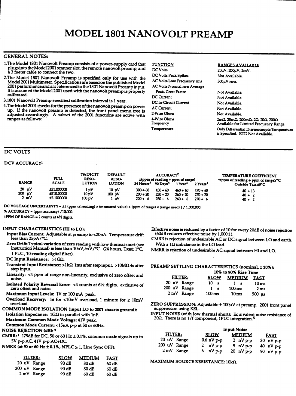
Page 75

Page 76

Page 77

B
Calibration Programs
Introduction
This appendix includes programs written in QuickBASIC
and T urbo C to aid you in calibrating the Model 1801. See
paragraph 5.2 in Section 5 for details on offset adjustments, recommended calibration equipment, test connections, and detailed calibration procedures.
Program requirements
In order to use the calibration programs, you will need the
following:
• IBM PC, AT, or compatible computer.
• IOtech Personal488, CEC PC-488, or National
Instruments PC-II or IIA IEEE-488 interface for the
computer.
• Shielded IEEE-488 cable(s) (Keithley Model 7007).
• MS-DOS or PC-DOS version 3.3 or later.
• Microsoft QuickBASIC version 4.0 or later, or Borland C Turbo C version 2.0 or later.
• IOtech Driver488 IEEE-488 bus driver, Rev. 2.3 or
later. (Note: recent versions of Driver488 may not
support other manufacturers' interface cards.)
one of the programs that controls the Fluke 5700A
calibrator, connect the calibrator to the IEEE-488 b us
as well. Be sure to use shielded IEEE-488 cables for
bus connections.
2. Turn on the computer, the Model 2001, and the calibrator. Allow the Model 2001 and 1801 to warm up
for at least two hours before performing calibration.
3. Make sure the Model 2001 is set for a primary
address of 16. You can check or change the address as
follows:
A. Press MENU, select GPIB, then press ENTER.
B. Select MODE, then press ENTER.
C. Select ADDRESSABLE, and press ENTER.
D. If the address is set correctly, press EXIT as nec-
essary to return to normal display.
E. To change the address, use the cursor keys to set
the address to the desired value, then press
ENTER. Press EXIT as necessary to return to
normal display.
4. If you are using the Fluke 5700A calibrator over the
bus (Programs B-3 and B-4), make sure that the calibrator primary address is at its factory default setting
of 4.
5. Make sure that the computer bus driver software is
properly initialized.
General program instructions
1. With the power off, connect the Model 2001 to the
IEEE-488 interface of the computer. If you are using
6. Enter the QuickBASIC or Turbo C editor, and type in
the desired program. Check thoroughly for errors,
then save it using a convenient filename.
7. Compile and run the program, and follow the prompts
on the screen to perform calibration.
B-1
Page 78

Calibration Programs
Program B-1. Calibration Program for Use with Any Suitable Calibrator (QuickBASIC Version)
' Model 1801 calibration program for use with any suitable
' DC voltage calibrator.
OPEN "\DEV\IEEEOUT" FOR OUTPUT AS #1 ' Open IEEE-488 output path.
OPEN "\DEV\IEEEIN" FOR INPUT AS #2 ' Open IEEE-488 input path.
IOCTL #1, "BREAK" ' Reset interface.
PRINT #1, "RESET" ' Warm start interface
PRINT #1, "CLEAR" ' Send DCL.
PRINT #1, "REMOTE 16" ' Put 2001 in remote.
PRINT #1, "TERM LF EOI" ' Set terminator to LF + EOI.
PRINT #1, "OUTPUT 16;:SYST:PRES;*CLS" ' Initialize 2001.
PRINT #1, "OUTPUT 16;*ESE 1;*SRE 32" ' Enable OPC and SRQ
C$ = ":CAL:UNPR:PRE:" ' 1801 partial command header.
'
GOSUB CheckOpt ' Check 1801 installation.
CLS ' Clear CRT.
PRINT "Model 1801 Nanovolt Preamplifier Calibration Program"
PRINT "Calibrator and Model 262 divider ratios must be set manually."
RESTORE CmdList
PRINT
PRINT "Set DC calibrator to external sense, 0V DC output."
PRINT "Place calibrator in operate mode."
PRINT
PRINT "Set 262 polarity to POS+ position."
PRINT "Wait two minutes for thermals to settle."
GOSUB KeyCheck
FOR I = 1 TO 7 ' Loop for all cal points.
READ Msg$, Cmd$ ' Read message, cal strings.
PRINT Msg$ ' Display prompt message.
IF I = 4 THEN PRINT "Set calibrator output to 200.000mV DC"
IF I < 7 THEN GOSUB KeyCheck ' Wait for operator input.
IF I < 7 THEN GOSUB Dly ' Settling time.
PRINT #1, "OUTPUT 16;"; C$; Cmd$; ";*OPC" ' Send cal command to 2001.
GOSUB CalEnd ' Wait until cal step ends.
NEXT I
GOSUB ErrCheck ' Check for errors.
INPUT "Enter calibration date (mm/dd/yy)"; D$
PRINT #1, "OUTPUT 16;:CAL:UNPR:PRE:DATE '"; D$; "'"
INPUT "Enter calibration due date (mm/dd/yy)"; D$
PRINT #1, "OUTPUT 16;:CAL:UNPR:PRE:NDUE '"; D$; "'"
PRINT #1, "OUTPUT 16;:CAL:UNPR:PRE:SAVE" ' Save calibration constants.
PRINT "Calibration completed."
END
'
KeyCheck: ' Check for key press routine.
PRINT
PRINT "Press any key to continue (ESC to abort program)."
Wai: I$ = INKEY$: IF I$ = "" THEN GOTO Wai
IF I$ = CHR$(27) THEN ' Abort if ESC is pressed.
CLOSE 1: CLOSE 2
PRINT "Program halted."
END
END IF
RETURN
'
B-2
Page 79

Calibration Programs
Program B-1. Calibration Program for Use with Any Suitable Calibrator (QuickBASIC Version) Continued
CalEnd: ' Check for cal step completion.
PRINT "Waiting for calibration step"; I; "completion..."
Stat: PRINT #1, "STATUS" ' Request bus status.
INPUT #2, ST$ ' Input status.
IF MID$(ST$, 11, 2) = "S0" THEN GOTO Stat ' Wait for operation complete.
PRINT #1, "OUTPUT 16;*ESR?" ' Clear OPC.
PRINT #1, "ENTER 16"
INPUT #2, S
PRINT #1, "SPOLL 16"
INPUT #2, S
RETURN
'
ErrCheck: ' Error check routine.
PRINT #1, "OUTPUT 16;:SYST:ERR?" ' Query error queue.
PRINT #1, "ENTER 16"
INPUT #2, E, Err$
IF E <> 0 THEN
PRINT ' If error is detected, error
PRINT Err$ ' is displayed, and program
PRINT "Calibration aborted." ' is halted.
BEEP
CLOSE 1: CLOSE 2
END
END IF
RETURN
'
Dly: ' Delay routine.
T = TIMER
Lp: IF (TIMER - T) < 5 THEN GOTO Lp
RETURN
'
CheckOpt: ' Check for 1801.
PRINT #1, "OUTPUT 16;*OPT?"
PRINT #1, "ENTER 16"
LINE INPUT #2, OPT$
IF INSTR(OPT$, "1801") = 0 THEN
PRINT "Model 1801 is not installed; program aborted."
END
END IF
RETURN
'
CmdList:
DATA "Set 262 divider ratio to 10^2.","Z1K"
DATA "Set 262 divider ratio to 10^3.","Z10K"
DATA "Set 262 divider ratio to 10^4.","Z100K"
DATA "Make sure divider is still set to 10^4.","FS100K 20E-6"
DATA "Set 262 divider ratio to 10^3.","FS10K 200E-6"
DATA "Set 262 divider ratio to 10^2.","FS1K 2E-3"
DATA "Calculating constants...","CALC"
B-3
Page 80

Calibration Programs
Program B-2. Calibration Program for Use with Any Suitable Calibrator (Turbo C Version)
/* Model 1801 calibration program for use with any suitable
DC voltage calibrator. */
#include "ieeeio.h"
#include <stdio.h>
#include <stdlib.h>
#include <conio.h>
#include <string.h>
main()
{
static char *msg[] = {
"Set 262 divider ratio to 10^2.",
"Set 262 divider ratio to 10^3.",
"Set 262 divider ratio to 10^4.",
"Make sure divider is still set to 10^4.",
"Set 262 divider ratio to 10^3.",
"Set 262 divider ratio to 10^2.",
"Calculating constants..."
};
static char *cmd[] = {
":cal:unpr:pre:z1k",":cal:unpr:pre:z10k",
":cal:unpr:pre:z100k",":cal:unpr:pre:fs100k 20e-6",
":cal:unpr:pre:fs10k 200e-6",
":cal:unpr:pre:fs1k 2e-3",
":cal:unpr:pre:calc"
};
void keypress(),errcheck(),checkopt();
char date[10];
int i,calend();
if (ieeeinit()==-1){
printf("Cannot initialize interface.\n");
exit(1);
}
ieeewt("remote 16\n"); /* Put 2001 in remote. */
ieeewt("clear\n"); /* Send DCL. */
ieeewt("term lf eoi\n"); /* Set terminator. */
ieeewt("output 16;:syst:pres;*cls\n"); /* Initialize 2001. */
ieeewt("output 16;*ese 1;*sre 32\n"); /* Enable OPC, SRQ. */
checkopt(); /* Check for 1801. */
clrscr(); /* Clear CRT. */
printf("Model 1801 Calibration Program.\n");
printf("Calibrator and Model 262 divider ratios"
" must be set manually.\n");
printf("Set calibrator to external sense, 0V DC output.\n"
"Place calibrator in operate mode.\n\n");
printf("Set 262 to POS+ polarity.\n");
printf("Wait two minutes for thermals to settle.\n");
keypress();
for(i=0;i<=6;i++) { /* Loop for cal points. */
printf("%s\n",msg[i]);
if(i==3) printf("Set calibrator output to "
"200.000mV.\n");
if (i<6) keypress();
B-4
Page 81

Calibration Programs
Program B-2. Calibration Program for Use with Any Suitable Calibrator (Turbo C Version) Continued
if (i<6) delay(5000);
ieeeprtf("output 16;%s;*opc\n",cmd[i]);
calend(i);
}
errcheck();
printf("Enter calibration date (mm/dd/yy): ");
scanf("%s",date);
ieeeprtf("output 16;:cal:unpr:pre:date '%s'\n",date);
printf("Enter calibration due date (mm/dd/yy): ");
scanf("%s",date);
ieeeprtf("output 16;:cal:unpr:pre:ndue '%s'\n",date);
ieeewt("output 16;:cal:unpr:pre:save\n");
printf("Calibration completed.\n");
}
void keypress() /* Wait for keypress. */
{
printf("Press any key to continue.\n");
while(kbhit()==0);
getch();
}
int calend(n) /* Check for cal end. */
int n;
{
char status[40];
int stat;
printf("Waiting for cal step %d completion.\n",n+1);
do {
ieeewt("status\n");
ieeerd(status);
}
while (status[11]=='0');
ieeewt("output 16;*esr?\n");
ieeewt("enter 16\n");
ieeescnf("%d",&stat);
ieeewt("spoll 16\n");
ieeescnf("%d",&stat);
}
void errcheck() /* Check for error. */
{
char errbuf[100];
ieeewt("output 16;:syst:err?\n");
ieeewt("enter 16\n");
ieeerd(errbuf);
if (atoi(errbuf) !=0){
printf("%s\n",errbuf);
printf("Calibration aborted.\n");
exit(1);
}
}
void checkopt() /* Check for 1801. */
{
char buf[40];
ieeewt("output 16;*opt?\n");
ieeewt("enter 16\n");
B-5
Page 82

Calibration Programs
Program B-2. Calibration Program for Use with Any Suitable Calibrator (Turbo C Version) Continued
ieeerd(buf);
if (strstr(buf,"1801") == NULL){
printf("Model 1801 is not installed;"
" program aborted.\n");
exit(1);
}
}
B-6
Page 83

Calibration Programs
Program B-3. Calibration Program for Use with Fluke 5700A Calibrator (QuickBASIC Version)
' Model 1801 calibration program for use only with the
' Fluke 5700A calibrator.
OPEN "\DEV\IEEEOUT" FOR OUTPUT AS #1 ' Open IEEE-488 output path.
OPEN "\DEV\IEEEIN" FOR INPUT AS #2 ' Open IEEE-488 input path.
IOCTL #1, "BREAK" ' Reset interface.
PRINT #1, "RESET" ' Warm start interface
PRINT #1, "CLEAR" ' Send DCL.
PRINT #1, "REMOTE 16" ' Put 2001 in remote.
PRINT #1, "REMOTE 04" ' Put 5700A in remote.
PRINT #1, "TERM LF EOI" ' Set terminator to LF + EOI.
PRINT #1, "OUTPUT 16;:SYST:PRES;*CLS" ' Initialize 2001.
PRINT #1, "OUTPUT 16;*ESE 1;*SRE 32" ' Enable OPC and SRQ.
PRINT #1, "OUTPUT 04;*RST;*CLS" ' Reset 5700A calibrator.
C$ = ":CAL:UNPR:PRE:" ' 1801 partial command header.
'
GOSUB CheckOpt ' Check 1801 installation.
CLS ' Clear CRT.
PRINT "Model 1801 Nanovolt Preamplifier Calibration Program"
PRINT "This program controls the Fluke 5700A Calibrator."
PRINT "Model 262 divider ratios must be set manually."
RESTORE CmdList
PRINT #1, "OUTPUT 04;OUT 1V,0HZ" ' Set 2.2V range.
PRINT #1, "OUTPUT 04;RANGELCK ON" ' Lock range.
PRINT #1, "OUTPUT 04;OUT 0V,0 HZ" ' Output 0V.
PRINT #1, "OUTPUT 04;OPER" ' Put calibrator in operate.
PRINT #1, "OUTPUT 04;EXTSENSE ON" ' Enable external sense.
PRINT
PRINT "Set 262 polarity to POS+ position."
PRINT "Wait two minutes for thermals to settle."
GOSUB KeyCheck
FOR I = 1 TO 7 ' Loop for all cal points.
IF I = 4 THEN PRINT #1, "OUTPUT 04;OUT 0.2 V,0 HZ" ' Output 200mV.
READ Msg$, Cmd$ ' Read message, cal strings.
PRINT Msg$ ' Display prompt message.
IF I < 7 THEN GOSUB KeyCheck ' Wait for operator input.
IF I < 7 THEN GOSUB Dly ' Settling time.
PRINT #1, "OUTPUT 16;"; C$; Cmd$; ";*OPC" ' Send cal command to 2001.
GOSUB CalEnd ' Wait until cal step ends.
NEXT I
PRINT #1, "OUTPUT 04;STBY" ' Put calibrator in standby.
GOSUB ErrCheck ' Check for errors.
INPUT "Enter calibration date (mm/dd/yy)"; D$
PRINT #1, "OUTPUT 16;:CAL:UNPR:PRE:DATE '"; D$; "'"
INPUT "Enter calibration due date (mm/dd/yy)"; D$
PRINT #1, "OUTPUT 16;:CAL:UNPR:PRE:NDUE '"; D$; "'"
PRINT #1, "OUTPUT 16;:CAL:UNPR:PRE:SAVE" ' Save calibration constants.
PRINT "Calibration completed."
END
'
KeyCheck: ' Check for key press routine.
PRINT
PRINT "Press any key to continue (ESC to abort program)."
Wai: I$ = INKEY$: IF I$ = "" THEN GOTO Wai
IF I$ = CHR$(27) THEN ' Abort if ESC is pressed.
PRINT #1, "OUTPUT 04;STBY"
B-7
Page 84

Calibration Programs
Program B-3. Calibration Program for Use with Fluke 5700A Calibrator (QuickBASIC Version) Continued
PRINT #1, "OUTPUT 16;:CAL:UNPR:PRE:ABOR"
CLOSE 1: CLOSE 2
PRINT "Program halted."
END
END IF
RETURN
'
CalEnd: ' Check for cal step completion.
PRINT "Waiting for calibration step"; I; "completion..."
Stat: PRINT #1, "STATUS" ' Request bus status.
INPUT #2, ST$ ' Input status.
IF MID$(ST$, 11, 2) = "S0" THEN GOTO Stat ' Wait for operation complete.
PRINT #1, "OUTPUT 16;*ESR?" ' Clear OPC.
PRINT #1, "ENTER 16"
INPUT #2, S
PRINT #1, "SPOLL 16"
INPUT #2, S
RETURN
'
ErrCheck: ' Error check routine.
PRINT #1, "OUTPUT 16;:SYST:ERR?" ' Query error queue.
PRINT #1, "ENTER 16"
INPUT #2, E, Err$
IF E <> 0 THEN
PRINT ' If error is detected, error
PRINT Err$ ' is displayed, and program
PRINT "Calibration aborted." ' is halted.
BEEP
CLOSE 1: CLOSE 2
END
END IF
RETURN
'
Dly: ' Delay routine.
T = TIMER
Lp: IF (TIMER - T) < 5 THEN GOTO Lp
RETURN
'
CheckOpt: ' Check for 1801.
PRINT #1, "OUTPUT 16;*OPT?"
PRINT #1, "ENTER 16"
LINE INPUT #2, OPT$
IF INSTR(OPT$, "1801") = 0 THEN
PRINT "Model 1801 is not installed; program aborted."
END
END IF
RETURN
'
CmdList:
DATA "Set 262 divider ratio to 10^2.","Z1K"
DATA "Set 262 divider ratio to 10^3.","Z10K"
DATA "Set 262 divider ratio to 10^4.","Z100K"
DATA "Make sure divider is still set to 10^4.","FS100K 20E-6"
DATA "Set 262 divider ratio to 10^3.","FS10K 200E-6"
DATA "Set 262 divider ratio to 10^2.","FS1K 2E-3"
DATA "Calculating constants...","CALC"
B-8
Page 85

Program B-4. Calibration Program for Use with Fluke 5700A Calibrator (Turbo C Version)
/* Model 1801 calibration program for use with the
Fluke 5700A calibrator. */
#include "ieeeio.h"
#include <stdio.h>
#include <stdlib.h>
#include <conio.h>
#include <string.h>
main()
{
static char *msg[] = {
"Set 262 divider ratio to 10^2.",
"Set 262 divider ratio to 10^3.",
"Set 262 divider ratio to 10^4.",
"Make sure divider is still set to 10^4.",
"Set 262 divider ratio to 10^3.",
"Set 262 divider ratio to 10^2.",
"Calculating constants..."
};
static char *cmd[] = {
":cal:unpr:pre:z1k",":cal:unpr:pre:z10k",
":cal:unpr:pre:z100k",":cal:unpr:pre:fs100k 20e-6",
":cal:unpr:pre:fs10k 200e-6",
":cal:unpr:pre:fs1k 2e-3",
":cal:unpr:pre:calc"
};
void keypress(),errcheck(),checkopt();
char date[10];
int i,calend();
if (ieeeinit()==-1){
printf("Cannot initialize interface.\n");
exit(1);
}
ieeewt("remote 16\n"); /* Put 2001 in remote. */
ieeewt("remote 04\n"); /* Put 5700A in remote. */
ieeewt("clear\n"); /* Send DCL. */
ieeewt("term lf eoi\n"); /* Set terminator. */
ieeewt("output 16;:syst:pres;*cls\n"); /* Initialize 2001. */
ieeewt("output 16;*ese 1;*sre 32\n"); /* Enable OPC, SRQ. */
ieeewt("output 04;*rst;*cls\n"); /* Reset 5700A. */
checkopt(); /* Check for 1801. */
clrscr(); /* Clear CRT. */
printf("Model 1801 Calibration Program.\n");
printf("This program controls the 5700A Calibrator.\n");
printf("Model 262 divider ratios must be set manually.\n\n");
ieeewt("output 04;out 1v,0 hz\n"); /* Set 2.2V range. */
ieeewt("output 04;rangelck on\n"); /* Lock range. */
ieeewt("output 04;extsense on\n"); /* Enable external sense */
ieeewt("output 04;out 0 v,0 hz\n"); /* Output 0V.*/
ieeewt("output 04;oper\n"); /* Calibrator in operate. */
printf("Set 262 to POS+ polarity.\n");
printf("Wait two minutes for thermals to settle.\n");
keypress();
for(i=0;i<=6;i++) { /* Loop for cal points. */
Calibration Programs
B-9
Page 86

Calibration Programs
Program B-4. Calibration Program for Use with Fluke 5700A Calibrator (Turbo C Version) Continued
if(i==3) ieeewt("output 04;out 0.2 v,0 hz\n");
printf("%s\n",msg[i]);
if (i<6) keypress();
if (i<6) delay(5000);
ieeeprtf("output 16;%s;*opc\n",cmd[i]);
calend(i);
}
ieeewt("output 04;stby\n");
errcheck();
printf("Enter calibration date (mm/dd/yy): ");
scanf("%s",date);
ieeeprtf("output 16;:cal:unpr:pre:date '%s’\n",date);
printf("Enter calibration due date (mm/dd/yy): ");
scanf("%s",date);
ieeeprtf("output 16;:cal:unpr:pre:ndue '%s’\n",date);
ieeewt("output 16;:cal:unpr:pre:save\n");
printf("Calibration completed.\n");
}
void keypress() /* Wait for keypress. */
{
printf("Press any key to continue.\n");
while(kbhit()==0);
getch();
}
int calend(n) /* Check for cal end. */
int n;
{
char status[40];
int stat;
printf("Waiting for cal step %d completion.\n",n+1);
do {
ieeewt("status\n");
ieeerd(status);
}
while (status[11]==’0’);
ieeewt("output 16;*esr?\n");
ieeewt("enter 16\n");
ieeescnf("%d",&stat);
ieeewt("spoll 16\n");
ieeescnf("%d",&stat);
}
void errcheck() /* Check for error. */
{
char errbuf[100];
ieeewt("output 16;:syst:err?\n");
ieeewt("enter 16\n");
ieeerd(errbuf);
if (atoi(errbuf) !=0){
printf("%s\n",errbuf);
printf("Calibration aborted.\n");
exit (1);
}
}
void checkopt() /* Check for 1801. */
{
B-10
Page 87

Calibration Programs
Program B-4. Calibration Program for Use with Fluke 5700A Calibrator (Turbo C Version) Continued
char buf[40];
ieeewt("output 16;*opt?\n");
ieeewt("enter 16\n");
ieeerd(buf);
if (strstr(buf,"1801") == NULL) {
printf("Model 1801 is not installed;"
" program aborted.\n");
exit(1);
}
}
B-11
Page 88

C
IEEE-488 Bus Command Summary
Table C-1 summarizes IEEE-488 bus commands associated exclusively with the Model 1801. Refer to the Model 2001
Operator’s Manual for additional commands that can be used with the Model 1801.
Table C-1
IEEE-488 bus command summary
Command Description
:INPut
:PREamp
:STATe <b>
:STATe?
:FILTer <name>
:FILTer?
[:SENSe[1]]
:TEMPerature
:DTCouple
:TYPE <type>
:TYPE?
:USLope <value>
:USLope?
:RTEMperature <value>
:RTEMperature?
:TRANsducer DTC
:TRANsducer?
Preamp control commands.
Enables (ON or 1) or disables (OFF or 0) preampliÞer.
Returns preamp state (1=ON, 0=OFF).
Selects preamp Þlter response (Name = SLOW | MEDium | FAST).
Returns preamp Þlter state (SLOW, MED, or FAST).
Temperature control commands.
Temperature path.
Differential path.
Select thermocouple type (type = J|K|T|E|R|S|B| USER).
Return thermocouple type (J|K|T|E|R|S|B| USER).
Select thermocouple slope (value = slope in V/¡C).
Return thermocouple slope (V/¡C).
Select reference thermocouple temperature (value = reference tem-
Return thermocouple reference temperature (¡C, ¡F, or K).
Select differential thermocouple transducer.
Return transducer type.
perature in ¡C, ¡F, or K).
C-1
Page 89

IEEE-488 Bus Command Summary
Table C-1 (Continued)
IEEE-488 bus command summary
Command Description
:CALibration
:UNPRotected
:PREamp
:G1K <value>
:G1K?
:G10K <value>
:G10K?
:G100K <value>
:G100K?
:Z1K
:Z10K
:Z100K
:FS1K <value>
:FS10K <value>
:FS100K <value>
:DATE Ò<string>Ó
:DATE?
:NDUE Ò<string>Ó
:NDUE?
:CALCulate
:SAVE
:ABORt
Calibration commands.
Commands not protected by CAL switch.
Preamp commands.
Directly enter 2mV gain.
Request 2mV gain constant.
Directly enter 200µV gain.
Request 200µV gain constant.
Directly enter 20µV gain.
Request 20µV gain constant.
Measure 2mV range zero.
Measure 200µV range zero.
Measure 20µV range zero.
Measure 2mV range full-scale <value>= 1E-3 to 2E-3
Measure 200µV range full- scale. <value> = 100E-6 to 200E-6.
Measure 20µV range full- scale. <value > = 10E-6 to 20E-6
Send calibration date.
Request calibration date.
Send calibration due date.
Request calibration due date.
Calculate calibration constants.
Save calibration constants in NVRAM.
Abort calibration procedure.
Notes:
1. Angle brackets (<>) are used to indicate parameter type. Do not include brackets in programming message.
2. Upper-case letters indicate command short form.
3. Brackets ([]) indicate command is optional.
4. Commands must be sent in order listed in Table 5-3.
C-2
Page 90

Index
A
AC voltage measurements 3-9
AC volts verification 4-6
B
Block diagram 5-10
C
Calibration 5-1
Calibration programs B-1
Card configuration 2-2
Card installation 2-5
Card removal 2-5
Component layouts and schematic
diagrams 6-1
Connections 2-6
D
DC voltage measurements 3-7
DC volts verification 4-3
Differential thermocouple temperature
measurements 3-14
E
Electromagnetic interference 3-22
Enabling Model 1801 operation 3-2
Environmental conditions 4-1, 5-1
F
Factory service 6-1
Features 1-1
Four-wire resistance measurements 3-11
Frequency measurements 3-11
G
Gain constants calibration 5-9
General information 1-1
General program instructions B-1
Ground loops 3-22
I
IEEE-488 bus command summary C-1
IEEE-488 bus operation 3-7
Input signal connections 2-7
Inspection for damage 1-2
Installation 2-1
Instruction manual 1-2
Introduction 1-1, 2-1, 3-1, 4-1, 5-1, 6-1,
B-1
L
Line power 4-2, 5-2
M
Magnetic fields 3-21
Manual addenda 1-2
Measurement considerations 3-18
Measurements 3-7
Minimum operating distance 2-9
Model 2001 compatibility 1-3
N
Normal calibration 5-4
O
Offset adjustments 5-2
Operating considerations 2-9
Operation 3-1
Operational differences 3-5
Optional accessories 1-3
Ordering information 6-1
Output connections to multimeter 2-7
P
Parts lists 6-1
Performance verification 4-1
Power supply cable 5-10
Power supply card 2-3, 5-10
Power supply card installation and
removal 2-5
Power supply card preparation 2-4
Power supply connections 2-6
Power-up detection 3-1
Preamp ON/OFF states 3-2
Preamplifier configuration menu 3-2
Preamplifier filtering 3-4
Preamplifier module 2-2, 5-10
Preamplifier operation 3-1
Principles of operation 5-10
Program requirements B-1
R
Recommended calibration
equipment 5-2
Recommended test equipment 4-2
Repacking for shipment 1-2
Replaceable parts 6-1
Resistance verification 4-6
Restoring default conditions 4-3
i-1
Page 91

S
Safety symbols and terms 1-2
Service information 5-1
Shielding 3-22
Shipment contents 1-2
Source resistance noise 3-20
Special handling of static-sensitive
devices 5-12
Specifications 1-2, A-1
T
Thermoelectric potentials 3-18
Troubleshooting 5-12
Troubleshooting access 5-12
Troubleshooting equipment 5-12
Troubleshooting procedure 5-12
U
Unpacking and inspection 1-2
Using the thermal isolation
container 2-9
V
Verification limits 4-2
Verification procedures 4-3
W
Warm-up period 4-2, 5-1
Warranty information 1-1
i-2
Page 92

Service Form
Model No. Serial No. Date
Name and Telephone No.
Company
List all control settings, describe problem and check boxes that apply to problem.
Intermittent
❏
❏
IEEE failure
Front panel operational
❏
Display or output (check one)
Drifts
❏
Unstable
❏
❏
Overload
❏
Calibration only
Data required
❏
(attach any additional sheets as necessary)
Show a block diagram of your measurement system including all instruments connected (whether power is turned on or not).
Also, describe signal source.
Analog output follows display
❏
❏
Obvious problem on power-up
All ranges or functions are bad
❏
Unable to zero
❏
Will not read applied input
❏
❏
CertiÞcate of calibration required
Particular range or function bad; specify
❏
❏
Batteries and fuses are OK
Checked all cables
❏
Where is the measurement being performed? (factory, controlled laboratory, out-of-doors, etc.)
What power line voltage is used? Ambient temperature? ¡F
Relative humidity? Other?
Any additional information. (If special modiÞcations have been made by the user, please describe.)
Be sure to include your name and phone number on this service form
.
Page 93

Specifications are subject to change without notice.
All Keithley trademarks and trade names are the property of Keithley Instruments, Inc. All other
trademarks and trade names are the property of their respective companies.
Keithley Instruments, Inc. 28775 Aurora Road • Cleveland, Ohio 44139 • 440-248-0400 • Fax: 440-248-6168
1-888-KEITHLEY (534-8453) • www.keithley.com
Sales Offices: BELGIUM: Bergensesteenweg 709 • B-1600 Sint-Pieters-Leeuw • 02-363 00 40 • Fax: 02/363 00 64
CHINA: Yuan Chen Xin Building, Room 705 • 12 Yumin Road, Dewai, Madian • Beijing 100029 • 8610-6202-2886 • Fax: 8610-6202-2892
FINLAND: Tietäjäntie 2 • 02130 Espoo • Phone: 09-54 75 08 10 • Fax: 09-25 10 51 00
FRANCE: 3, allée des Garays • 91127 Palaiseau Cédex • 01-64 53 20 20 • Fax: 01-60 11 77 26
GERMANY: Landsberger Strasse 65 • 82110 Germering • 089/84 93 07-40 • Fax: 089/84 93 07-34
GREAT BRITAIN: Unit 2 Commerce Park, Brunel Road • Theale • Berkshire RG7 4AB • 0118 929 7500 • Fax: 0118 929 7519
INDIA: Flat 2B, Willocrissa • 14, Rest House Crescent • Bangalore 560 001 • 91-80-509-1320/21 • Fax: 91-80-509-1322
ITALY: Viale San Gimignano, 38 • 20146 Milano • 02-48 39 16 01 • Fax: 02-48 30 22 74
JAPAN: New Pier Takeshiba North Tower 13F • 11-1, Kaigan 1-chome • Minato-ku, Tokyo 105-0022 • 81-3-5733-7555 • Fax: 81-3-5733-7556
KOREA: FL., URI Building • 2-14 Yangjae-Dong • Seocho-Gu, Seoul 137-130 • 82-2-574-7778 • Fax: 82-2-574-7838
NETHERLANDS: Postbus 559 • 4200 AN Gorinchem • 0183-635333 • Fax: 0183-630821
SWEDEN: c/o Regus Business Centre • Frosundaviks Allé 15, 4tr • 169 70 Solna • 08-509 04 679 • Fax: 08-655 26 10
SWITZERLAND: Kriesbachstrasse 4 • 8600 Dübendorf • 01-821 94 44 • Fax: 01-820 30 81
TAIWAN: 1FL., 85 Po Ai Street • Hsinchu, Taiwan, R.O.C. • 886-3-572-9077• Fax: 886-3-572-9031
© Copyright 2001 Keithley Instruments, Inc.
Printed in the U.S.A.
2/02
 Loading...