

Page 1

“The Right Control for Your Application.”
12095 NW 39 Street, Coral Springs, FL 33065-2516
KB Electronics, Inc. Telephone: 954-346-4900; Fax: 954-346-3377
6LJQDO,VRODWRU6,0*3DUW1R,QVWDOODWLRQDQG:LULQJ,QVWUXFWLRQV
This document is supplied with Signal Isolator SIMG only.
Warning! Before installing the SIMG onto the KBMG, the AC power must be disconnected.
The following Installation and Wiring instructions are to be used as a supplement to the SIMG Installation and Operating Instructions Manual
(Part No. A40269). Refer to the SIMG Installation and Operating Instructions Manual for specific and external signal following connections.
See Figures 1 - 4, on page 2.
Tools required for installation: small flat blade screwdriver and long nose pliers.
Notes: 1. To install the SIMG, be sure the Top Panel of the KBMG 2-Piece Finger-Safe Cover (FSC) is not installed. 2. All trimpots and
jumpers, on the KBMG, must be set before installing the SIMG.
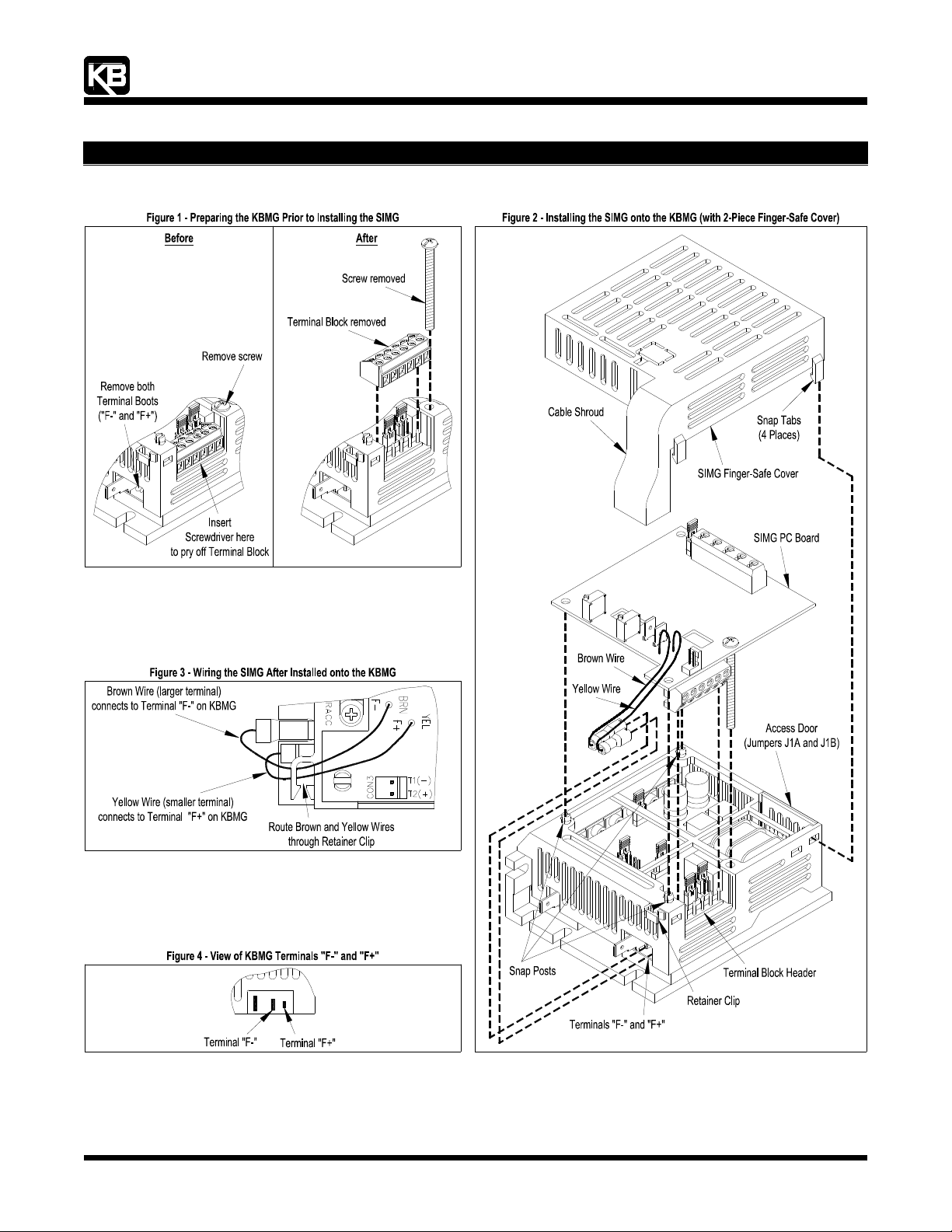
1 Preparing the KBMG Prior to Installing the SIMG - See Figure 1.
1.1 Insert the flat blade screwdriver between theKBMG PC Board and Terminal Block TB1 and gently pry it off. Discard the Terminal
Block.
Note: When prying off Terminal Block TB1, care should be taken to not scratch circuit traces that are on the PC Board surface.
1.2 Using a flat blade (or Phillips) screwdriver, remove the screw from the KBMG FSC. Retain this screw for use in Section 2.3, below.
1.3 Using long nose pliers, remove and discard the Terminal Boots that are factory installed on Terminals "F-" and "F+" on the KBMG.
2 Installing the SIMG onto the KBMG - See Figure 2.
2.1 Align and gently push the Terminal Block on the SIMG onto the Terminal Block Header on the KBMG.
2.2 Align the (3) Holes on the SIMG with the (3) Snap Posts on the KBMG FSC. Gently press the SIMG Board onto the (3) Snap Posts.
Apply pressure at each Snap Post.
2.3 Install the Screw, that was removed in Section 1.2, above, and gently tighten it to secure the SIMG onto the KBMG FSC. Do not
overtighten.
3 Wiring the SIMG After Installed onto the KBMG - See Figures 3 and 4.
Note: On older SIMG models, the Brown and Yellow Wires had to be crisscrossed. On this SIMG model, the Brown and Yellow Wires are
not crisscrossed. See Figures 2 and 3.
3.1 Carefully insert the Brown and Yellow Wires through the Retainer Clip on the KBMG FSC.
3.2 Connect the Brown Wire (larger terminal) to Terminal "F-" on the KBMG.
3.3 Connect the Yellow Wire (smaller terminal) to Terminal "F+" on the KBMG.
4 Installing the SIMG Finger-Safe Cover - See Figure 2.
Align the (4) Snap Tabs on the SIMG FSC with the (4) slots on the KBMG FSC. The Cable Shroud must be positioned over the Brown
and Yellow Wires. Apply pressure to snap the cover into position.
Note: Be sure that the Brown and Yellow Wires are centered in the Retaining Clip so the wires are not damaged by the Cable Shroud.
The SIMG installation is now complete.
(A40144) - Rev. A00 - 9/1/2004 - Z3348A00 Page 1 of 2
Page 2
“The Right Control for Your Application.”
12095 NW 39 Street, Coral Springs, FL 33065-2516
KB Electronics, Inc. Telephone: 954-346-4900; Fax: 954-346-3377
6LJQDO,VRODWRU6,0*3DUW1R,QVWDOODWLRQDQG:LULQJ,QVWUXFWLRQV
(A40144) - Rev. A00 - 9/1/2004 - Z3348A00 Page 2 of 2
Page 3
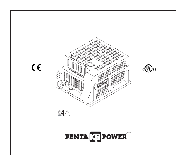
INSTALLATION AND OPERATING INSTRUCTIONS
MODEL SIMG
KB Part No. 8832 — Signal Isolator for KBMG-212D Regenerative Drive
See Safety Warning on Page 1
The information contained in this manual is intended to be accurate. However, the Manufacturer
retains the right to make changes in design which may not be included herein.
A COMPLETE LINE OF MOTOR DRIVES
© 2000 KB Electronics, Inc.
!
Pending
™
Page 4

TABLE OF CONTENTS
Section Page
i. Safety Warning . . . . . . . . . . . . . . . . . . . . . . . . . . . . . . . . . . . . . . . . . . . . . . . . . . . . . . . . . . 1
I. Introduction . . . . . . . . . . . . . . . . . . . . . . . . . . . . . . . . . . . . . . . . . . . . . . . . . . . . . . . . . . . . 2
II. Installation Instructions . . . . . . . . . . . . . . . . . . . . . . . . . . . . . . . . . . . . . . . . . . . . . . . . . . . . 6
III. Connections to the SIMG . . . . . . . . . . . . . . . . . . . . . . . . . . . . . . . . . . . . . . . . . . . . . . . . . 12
IV. Calibration Procedure . . . . . . . . . . . . . . . . . . . . . . . . . . . . . . . . . . . . . . . . . . . . . . . . . . . .16
V. Installing the SIMG Finger-Safe Cover . . . . . . . . . . . . . . . . . . . . . . . . . . . . . . . . . . . . . . . 17
VI. Limited Warranty . . . . . . . . . . . . . . . . . . . . . . . . . . . . . . . . . . . . . . . . . . . . . . . . . . . . . . . 18
Tables
1. General Performance Specifications . . . . . . . . . . . . . . . . . . . . . . . . . . . . . . . . . . . . . . . . . . 6
2. Terminal Block Wiring Information . . . . . . . . . . . . . . . . . . . . . . . . . . . . . . . . . . . . . . . . . . . 12
3. Resistor for Signal Following from Armature Voltage . . . . . . . . . . . . . . . . . . . . . . . . . . . . .14
Figures
1. Control Layout . . . . . . . . . . . . . . . . . . . . . . . . . . . . . . . . . . . . . . . . . . . . . . . . . . . . . . . . . . 3
2A. Mechanical Specifications . . . . . . . . . . . . . . . . . . . . . . . . . . . . . . . . . . . . . . . . . . . . . . . . . .4
2B. Mechanical Specifications (Continued) . . . . . . . . . . . . . . . . . . . . . . . . . . . . . . . . . . . . . . . . 5
3. KBMG/SIMG Assembly Diagram . . . . . . . . . . . . . . . . . . . . . . . . . . . . . . . . . . . . . . . . . . . . . 7
4. Removing the KBMG Finger-Safe Cover . . . . . . . . . . . . . . . . . . . . . . . . . . . . . . . . . . . . . . . 8
5. Removing Terminal Block TB1 . . . . . . . . . . . . . . . . . . . . . . . . . . . . . . . . . . . . . . . . . . . . . . 9
6. Removing the KBMG Finger-Safe Cover Panel . . . . . . . . . . . . . . . . . . . . . . . . . . . . . . . . . . 9
7. Removing the KBMG Finger-Safe Cover Field Tab . . . . . . . . . . . . . . . . . . . . . . . . . . . . . . . 9
8. Connection Diagram . . . . . . . . . . . . . . . . . . . . . . . . . . . . . . . . . . . . . . . . . . . . . . . . . . . . . 10
9. Installing Field Connector . . . . . . . . . . . . . . . . . . . . . . . . . . . . . . . . . . . . . . . . . . . . . . . . . 11
10. Voltage Following Connection . . . . . . . . . . . . . . . . . . . . . . . . . . . . . . . . . . . . . . . . . . . . . . 12
11. Main Speed Potentiometer Connections . . . . . . . . . . . . . . . . . . . . . . . . . . . . . . . . . . . . . . 13
12. Signal Following from Armature Voltage . . . . . . . . . . . . . . . . . . . . . . . . . . . . . . . . . . . . . . .14
13. Enable Switch Connection . . . . . . . . . . . . . . . . . . . . . . . . . . . . . . . . . . . . . . . . . . . . . . . . 16
14. Removing The SIMG Finger Safe Cover Field Tab . . . . . . . . . . . . . . . . . . . . . . . . . . . . . . 17
ii
Page 5
1
i. SAFETY WARNING! Please read carefully:
Be sure to follow all instructions carefully. Fire and/or electrocution can result due to
improper use of this product.
This product should be installed and serviced by a qualified technician, electrician, or
electrical maintenance person familiar with its operation and the hazard involved. Proper
installation, which includes wiring, mounting in proper enclosure, fusing or other over current protection and grounding, can reduce the chance of electric shocks, fires, or explosion in this product or products used with this product, such as electric motors, switches,
coils, solenoids, and relays. Eye protection must be worn and insulated adjustment tools
must be used when working with control under power. This product is constructed of
materials (plastics, metals, carbon, silicon, etc.) Which may be a potential hazard.
Proper shielding, grounding, and filtering of this product can reduce the emission of radio
frequency interference (RFI) which may adversely affect sensitive electronic equipment.
If information is required on this product, contact our factory. It is the responsibility of the
equipment manufacturer and individual installer to supply this safety warning to the ultimate user of this product. (SW effective 11/92)
This control contains electronic start/stop and enable circuits that can be used to start
and stop the control. However, these circuits are never to be used as safety disconnects
since they are not fail-safe. Use only the AC line for this purpose.
!
This product complies with all CE directives pertinent at the time of manufacture.
Contact factory for detailed installation instructions and Declaration of Conformity.
Page 6

I. INTRODUCTION
Thank you for purchasing the SIMG Bipolar Signal Isolator (P/N 8832). KB
Electronics, Inc. is committed to providing total customer satisfaction by producing quality products that are easy to install and operate. The SIMG is
manufactured with surface mount components incorporating advanced circuitry and technology.
The SIMG provides input isolation and is used to isolate, amplify, and condition DC voltage signals from any external source (power supplies, motors,
tachometer generators, transducers, and potentiometers). The isolated output voltage of the SIMG provides input signals to the KBMG-212D (hereinafter referred to as KBMG) Regenerative Drive (P/N 8831). In also provides isolation for motor direction switching and an isolated power supply for
transducer or potentiometer operation. The PWR LED provides indication
that power is applied.
All input connections (+15, -15, SIG, COM, and EN) are made via a barrier
terminal block and are isolated from AC line and motor wiring.
The SIMG is factory calibrated to accept a signal input voltage of -10V to
+10V DC. OFFSET and MAX trimpots are provided in order to recalibrate the
SIMG for specific applications.
2
Page 7
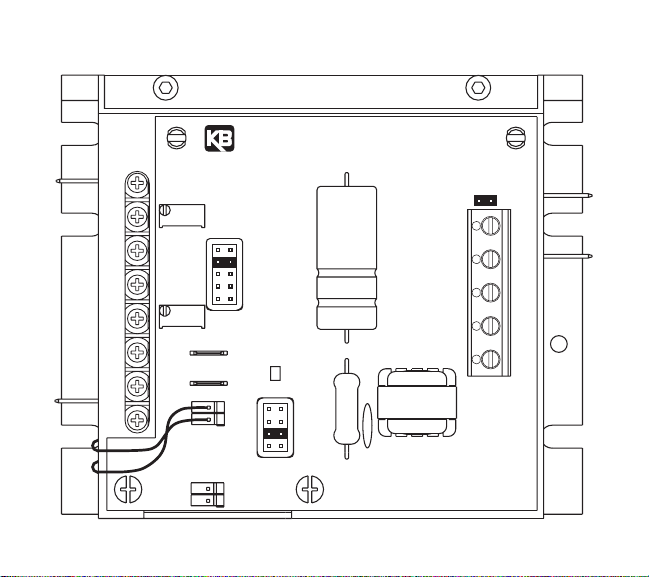
FIGURE 1 – CONTROL LAYOUT
(Illustrates Factory Setting of Jumpers and Approximate Trimpot Settings)
3
SIMG BIPOLAR SIGNAL ISOLATOR
M1
DB RESP
MAX
10A
7.5
5.0
2.5
1.7A
OFFSET
F-
M2
RACCMAXFCLIR RCL FACC
F-
F+
F+
A180
PWR
T50
T7
A90
TACH
F+
F-
CON3
CON2
T1(-)
T2(+)
ENABLE
J1
TB1
COM ENSIG
-15V+15V
L2
L1
Page 8
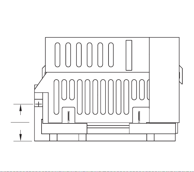
FIGURE 2A – MECHANICAL SPECIFICATIONS (INCHES / mm)
(Shown Mounted onto KBMG)
4
0.95
[24.21]
Page 9

FIGURE 2B – MECHANICAL SPECIFICATIONS (INCHES / mm)
(Shown Mounted onto KBMG)
5
2.67
[67.92]
0.48
[12.32]
3.80
[96.52]
4.68
[118.99]
3.80
[96.65]
2.50
[63.50]
0.75
[19.05]
L2
L1
DB RESP
M1
0.19
[4.83] TYP
RACCMAXFCLIR RCL FACC
M2
Page 10

TABLE 1 – GENERAL PERFORMANCE SPECIFICATIONS
II. INSTALLATION INSTRUCTIONS: Mounting the SIMG onto the KBMG
See figure 3 on page 7. Note: This figure is also supplied as a separate drawing.
Warning! Make sure all power is disconnected from the KBMG before
proceeding
.
A. Removing the KBMG Finger-Safe Cover
If a finger-safe cover is not installed on the KBMG, proceed to section IIC (Modifying
the KBMG Finger-Safe cover). If a finger-safe cover is installed on the KBMG,
remove the two (2) socket head 5-40 X 5/16” screws located at the rear of the KBMG
using the supplied 3/32” hex key. Also, remove the two (2) 6-32 X 1-3/4” screws
located on either side of terminal block TB1. See figure 4 on page 8.
6
—
±5 to ±25
MAX Trimpot Range (with 10V DC Input) (% Speed)
Parameter Specification Factory Setting
Voltage Following Input Range (V DC) -10 to +10
Potentiometer Operation (kΩ) 5 —
OFFSET Trimpot Range (with 0V DC Input) (% Speed) ± 50 0
+15V DC and -15V DC Power Supply Max. Current Rating (mA DC)
0 – 110 100
25
—
Forward, Reverse, and Enable Input Switch Types
Dry Contact or
Open Collector
Input/Output Linearity (%) 0.1
—
Thermal Drift (mV/ ºC) 0.4 —
Ambient Operating Temperature Range (ºC) 0 – 50
—
!
Page 11

B. Removing Terminal Block
TB1 from the KBMG
Remove terminal block TB1 from
the KBMG by rocking it back and
forth or using a screwdriver to gently pry it off. See figure 5 on page
9. The removed terminal block
TB1 will not be used and may be
discarded.
C. Modifying the KBMG Finger-
Safe Cover
Once the KBMG finger-safe cover
is removed, it has to be modified to
accommodate the SIMG. Cut out
the finger-safe cover panel
at seven (7) places as
shown in figure 6 on page
9. (Note: Some fingersafe covers may already
have the panel removed.)
To access the field terminals (F+ and F- on the
KBMG) cut out the field
tab of the KBMG fingersafe cover at three (3)
places as shown in figure
7 on page 9.
7
FIGURE 3 – KBMG/SIMG ASSEMBLY DIAGRAM
Snap on cover
(4 places)
SIMG
Finger-Safe Cover
6-32 x 1-3/4" Screws
(2 places)
5-40 x 5/16"
Screws
(2 places)
Cable
Assembly
Note:
Yellow to F+
Brown to F-
SIMG
KBMG
Finger-Safe Cover
KBMG
Page 12

D. Installing the KBMG Finger-
Safe Cover
Once the KBMG finger-safe
cover has been modified, it
can be installed onto the
KBMG. Initially, use only the
two (2) 5-40 X 5/16” socket
head screws, using the supplied 3/32” hex key. Do not
over tighten these screws or
damage may result to the
KBMG finger-safe cover.
Note: All jumpers on the
KBMG must be set to their
appropriate positions
before installing the
KBMG finger-safe cover.
E. Installing the SIMG onto
the KBMG
The terminal block located
on the bottom of the SIMG
plugs onto the six (6) header
pins where TB1 was
removed from the KBMG.
The two holes on the back of
the SIMG snap onto the finger-safe cover.
8
FIGURE 4 – REMOVING THE KBMG
FINGER-SAFE COVER
5-40 x 5/16"
Screws
KBMG
Finger-Safe
Cover
6-32 x 1-3/4"
KBMG
Page 13

Use the two (2) 6-32 X 1-3/4”
screws previously removed to
secure the SIMG to the KBMG. Do
not over tighten these screws or
damage may result to the SIMG and
KBMG. See figure 3 on page 7.
9
FIGURE 5 –
REMOVING
TERMINAL
BLOCK TB1
FIGURE 6 – REMOVING THE KBMG
FINGER-SAFE COVER PANEL
FIGURE 7 – REMOVING THE KBMG
FINGER-SAFE FIELD TAB
Terminal Block
TB1
KBMG
KBMG Finger-Safe Cover
Remove Panel (cut 7 places) to Install SIMG.
KBMG Finger-Safe Cover
Remove Tab (cut 3 places) to Access Field Terminals.
Page 14

FIGURE 8 – CONNECTION DIAGRAM
10
ARMATURE
M1
DB RESP
+
IR
RCL FCL MAX FACC
A
-
M2
RACC
F-
F+
-+
G
DC TACHOMETER
GENERATOR
SIMG BIPOLAR SIGNAL ISOLATOR
MAX
10A
7.5
5.0
2.5
1.7A
OFFSET
F-
F+
F+
F-
CON2
CON3
PWR
T50
T7
A180
A90
T1(-)
TACH
T2(+)
ENABLE
J1
-
FIELD
(SHUNT MOTORS ONLY)
+
L2
AC
LINE
L1
SIG COM EN
+15V -15V
TB1
GROUND
Page 15

F. Wiring the SIMG to the KBMG
See figure 8 on page 10.
The SIMG is powered from the KBMG with a connector that is installed from the
SIMG CON2 to the KBMG F+ and F- terminals. The yellow wire connects to the
KBMG F+ terminal and the brown wire connects to the KBMG F- terminal. When the
field connector is properly installed the wires should cross over each other. See figure 9. If the connector is wired incorrectly, the SIMG PWR LED will not illuminate
and the control will not operate.
Note: It is recommended that these wires be twist-
ed at least three (3) times to help reduce noise.
11
FIGURE 9 – INSTALLING
FIELD CONNECTOR
Page 16

III. Connections to the SIMG
Safety Warning! Do not use FWD-STOP-REV contacts as a safety discon-
nect since they are not fail-safe. Use only the AC line for this purpose.
Note: SIMG Enable jumper J1 must be installed, or a connection must be made
between EN and COM terminals of SIMG TB1 in order for the KBMG to operate.
A. Voltage Following
– Uses a
voltage source to vary motor
speed. See figure 10. Connect
the voltage source to TB1 terminals SIG and COM. When a
0V DC signal is applied, the
control will operate at the minimum set speed (set by the
OFFSET trimpot on the SIMG).
When a 10V DC signal is
applied, the motor will operate
at the maximum set speed (set
by the MAX trimpot on the SIMG).
Applying a positive (+) signal to SIG terminal, with respect to COM terminal, will operate the motor in the forward direction.
12
3.5
Connection Designation
Supply Wire Gauge (AWG – Cu)
Maximum Tightening Torque
(in-lbs)
MaximumMinimum
Logic Connections 24 14
TABLE 2 – TERMINAL BLOCK (TB1) WIRING INFORMATION
FIGURE 10 – VOLTAGE FOLLOWING
CONNECTION
!
± 10VDC
VDC
(KBMG Jumper J4 in 10V Position)
(SIMG Enable Jumper J1 Installed)
J1
EN COM SIG -15 +15
TB1
Page 17

Applying a negative (-) signal to SIG terminal, with respect to COM terminal, will
operate the motor in the reverse direction.
13
FIGURE 11 – MAIN SPEED POTENTIOMETER CONNECTIONS
(KBMG Jumper J4 in 15V Position, SIMG Enable Jumper J1 Installed)
A. B.
Forward Reverse
5K
5K
J1
EN COM SIG -15 +15
TB1
J1
EN COM SIG -15 +15
Unidirectional With Reversing Contact Bidirectional Potentiometer
D.
5K
J1
EN COM SIG -15 +15
REV
STOP
FWD
TB1
C.
J1
EN COM SIG -15 +15
REV FWD
5K
TB1
TB1
Page 18

B. Signal Following from
Armature Voltage – Uses
motor armature voltage as a
signal input. If the signal input
voltage applied to the SIMG is
derived from a motor armature
voltage output, it is necessary
to install a 1/4W resistor in
series with the signal lead into
the SIMG. For a 90V DC
motor, install a 150K resistor.
for a 180V DC motor, install a
330K resistor.
C. Unidirectional Potentiometer
Operation (Forward) – Uses a
potentiometer to vary motor speed.
See figure 11A on page 13.
Connect the 5K potentiometer to
TB1 terminals marked “SIG” (wiper
of potentiometer), “+15V” (high side
of potentiometer), and “COM” (low
side of potentiometer). Use the
potentiometer to vary motor speed.
If the motor is not running in the
desired direction, either reconnect
the high side of the potentiometer to TB1 terminal marked “-15V” or reverse the
motor leads.
14
330K
Armature Voltage
Range (VDC)
1/4W Resistor (Ω)
0 – ± 90 150K
0 – ± 180
FIGURE 12 – SIGNAL FOLLOWING FROM
ARMATURE VOLTAGE
TABLE 3 – RESISTOR FOR
SIGNAL FOLLOWING FROM
ARMATURE VOLTAGE
Armature
+
A
-
J1
EN COM SIG -15 +15
1/4W Resistor
(See Table 3)
TB1
Page 19

D. Unidirectional Potentiometer Operation (Reverse) – Uses a potentiometer to vary
motor speed. See figure 11B on page 13. Connect the 5K potentiometer to TB1 terminals marked “SIG” (wiper of potentiometer), “-15V” (high side of potentiometer),
and “COM” (low side of potentiometer). Use the potentiometer to vary motor speed
and the switching device to select motor direction. If the motor is not running in the
desired direction, either reconnect the high side of the potentiometer to TB1 terminal
marked “+15V” or reverse the motor leads.
E. Bidirectional Potentiometer Operation – Uses a potentiometer to vary motor
speed and direction. See figure 11C on page 13. Connect the 5K potentiometer to
TB1 terminals marked “SIG” (wiper of potentiometer), “+15V” (high side of potentiometer), and “-15V” (low side of potentiometer). Use the potentiometer to vary
motor speed and direction.
When the potentiometer is in the center position, the control output can be set to
zero, using the OFFSET trimpot. Rotating the trimpot clockwise will cause the motor
to rotate in the forward direction. Rotating the potentiometer counterclockwise will
cause the motor to rotate in the reverse direction.
F. Unidirectional Potentiometer with Reversing Contacts – Uses a potentiometer to
vary motor speed. See figure 11D on page 13. Connect the 5K potentiometer to TB1
terminals marked “SIG” (wiper of potentiometer), “+15V” (high side of potentiometer),
and “COM” (low side of potentiometer). Use the potentiometer to vary motor speed
and the switching device to select motor direction. When the potentiometer is set to
0% (fully counterclockwise), the motor will operate at the minimum set speed (set by
the OFFSET trimpot on the SIMG). When the potentiometer is set to 100% (fully
clockwise) the motor will operate at full speed (set by the MAX trimpot on the SIMG).
15
Page 20

G. Enable Switch Connection
Safety Warning!
Do
not use Enable or
Start/Stop contacts as a safety
disconnect since they are not
fail-safe. Use only the AC line
for this purpose. See figure 13.
If a Start/Stop function is
required, remove SIMG Enable
jumper J1 and wire a switch to
EN and COM terminals of
SIMG TB1. When the switch is
opened, the control will stop.
When the switch is closed, the
control will operate.
H. Tachometer Generator Connection
See figure 8 on page 10. To wire a 7V or 50V per 1000RPM tachometer generator
to the SIMG, connect the positive (+) side of the tachometer generator to terminal
“T2” and the negative (-) side of the tachometer generator to terminal “T1“ of the
SIMG.
Note: If the positive (+) and negative (-) tachometer generator connections
are not connected as described above, the motor will run at full speed only.
I. Motor Field Connection
If a shunt wound motor is used, the motor field wires connect to F+ and F- terminals
on the SIMG. To access these terminals, cut out the field tab of the SIMG finger-safe
cover at three (3) places as shown in figure 14 on page 17.
16
FIGURE 13 – ENABLE SWITCH CONNECTION
(SIMG Enable Jumper J1 Removed)
!
Enable
Open to Stop
J1
EN COM SIG -15 +15
TB1
Page 21

17
FIGURE 14 – REMOVING THE SIMG FINGER-SAFE COVER FIELD TAB
SIMG Finger-Safe Cover
Cut Out Tab (3 Places) to Access Field Terminals.
(For Shunt Wound Motors Only.)
Page 22

IV. CALIBRATION PROCEDURE
(See Safety Warning, on page 1)
The SIMG is factory calibrated, but readjustments to the OFFSET and MAX trimpots can
be made to customize for a particular signal input requirement. It may be necessary to
repeat the calibration steps to achieve accurate settings.
A. Unidirectional Voltage Following Calibration
See figure 10 on page 12.
1. Apply 0V DC input signal (or connect SIG and COM terminals).
2. Monitor the KBMG output and adjust the OFFSET trimpot on the SIMG for the
desired minimum setting.
3. Apply the maximum voltage input signal.
4. Monitor the KBMG output voltage and adjust the MAX trimpot on the SIMG for the
desired maximum setting.
B. Unidirectional Potentiometer Operation Calibration:
See figure 11A, B or C on page 13.
1. Set potentiometer to 0% rotation (fully counterclockwise).
2. Monitor the KBMG output and adjust the OFFSET trimpot on the SIMG for the
desired minimum setting.
3. Set potentiometer to 100% rotation (fully clockwise).
4. Monitor the KBMG output voltage and adjust the MAX trimpot on the SIMG for the
desired maximum setting.
18
Page 23

V. INSTALLING the SIMG FINGER-SAFE COVER
After all adjustments and wiring have been completed on the KBMG and the SIMG,
install the SIMG finger-safe cover onto the KBMG finger-safe cover by snapping the four
(4) clips of the SIMG finger-safe cover into the four (4) slots of the KBMG finger-safe
cover.
Note: Ensure that the yellow and brown field wires (from CON2 of the SIMG to F+ and
F- terminals of the KBMG) are within the shroud of the SIMG finger-safe cover. See figure 3 on page 7.
19
Page 24

– NOTES –
20
Page 25

– NOTES –
21
Page 26

VI. LIMITED WARRANTY
For a period of 18 months from the date of original purchase, KB Electronics, Inc. will
repair or replace, without charge, devices which our examination proves to be defective
in material or workmanship. This warranty is valid if the unit has not been tampered with
by unauthorized persons, misused, abused, or improperly installed and has been used in
accordance with the instructions and/or ratings supplied. The foregoing is in lieu of any
other warranty or guarantee, expressed or implied. KB Electronics, Inc. is not responsible for any expense, including installation and removal, inconvenience, or consequential
damage, including injury to any person, caused by items of our manufacture or sale.
Some states do not allow certain exclusions or limitations found in this warranty and
therefore they may not apply to you. In any event, the total liability of KB Electronics, Inc.,
under any circumstance, shall not exceed the full purchase price of this product.
(Rev 2/2000)
KB Electronics, Inc.
12095 NW 39th Street, Coral Springs, FL 33065-2516 • (954) 346-4900 • Fax (954) 346-3377
Outside Florida Call TOLL FREE (800) 221-6570 • E-mail – info@kbelectronics.com
www.kbelectronics.com
(A40269) – Rev. A – 4/2000
 Loading...