

'".
HAYNES
SERVICE
&
REPAIR
MANUAL
(GPZ600R.
GPH600R.
nlDJa
600R
&
ZH750
(GPH750R. ninja
750R)
'85
to
'97
"Haynes Manuals just cannot
be
beaten"
M:Jlor
C\'CIe
News
-
--
-------
COLOUR
wiring
diagrams
All manuals and user guides at all-guides.com
all-guides.com
•
Kawasaki
ZX600
&
750
Fours
Service and Repair Manual
by Bob Henderson
and John H Haynes
Member of the Guild of Motoring Writers
Models
covered
ZX600A (GPZ600R). 592cc. UK 1985 through 1990
ZX600A (Ninja 600R). 592cc. US 1985 through 1987
ZX600B alumininum frame model (Ninja 600RX). 592cc. US 1987
ZX600C (GPX600R). 592cc.
UK
1988 through 1996
ZX600C (Ninja 600R). 592cc. US 1988 through 1997
ZX750F (GPX750A). 748cc. UK 1987 through 1991
ZX750F (Ninja 7S0R). 748cc. US 1987 through 1990
C H
ayne.
Pubtlahlng 1999
A book
In
lhe
Hayne.
Service and Repair Manual
Serl"
PrInted in the USA
Haynes Publishing
Sparkford, Yeovil, Somerset 8A22 7 JJ, England
Hayn
es Nort
h America, Inc
(178()-.260-3Y3)
All
lights
,..
..
rHd.
No
part
of
this
book
may
be
reproduced
or
trans
mitted
In any
lorm
or
by
any
means,
electronic
or
machanical,
including
photoeopyil'lg,
rKOrding
or
by
any
information
ItOf'lllil8
or
rwtrieval system,
withotlt
pennl,lIon
In
writing
from
tIw
eopyright
holder.
861
Lawrence
Drive,
Newbury Park, California 91320, USA
ISBN 1
85980
230 4
Libllory
01
CongrHl
Catalog
Card
Numt:.r
81.12743
British Ubrary Cataloguing In
Pub~cation
o.ta
A catalogue record lor this book is
a~ailabkllrom
the Bntl$h Ubrary.
Edit
ions
Haynes
4, Rue
de
l'Abreuvoir
92415 COURBEVOIE CEDEX, France
Hayn
es
Publishing Nordiska
AS
Box 1504,
751
45
UPPSAlA,
Sweden
All manuals and user guides at all-guides.com

Contents
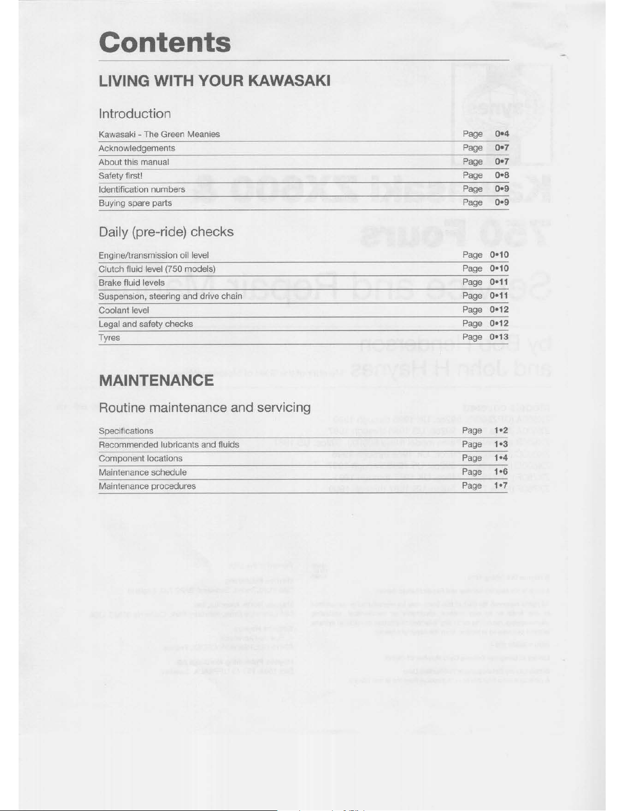
LIVING WITH YOUR KAWASAKI
Introduction
Kawasaki - The Green Meanies
Page
0·'
Acknowledgements
Page
0·7
About this manual
Page
0·7
Safety first!
Page
0·8
Identification numbers
Page
0·.
Buying spare parts
Page
0·9
Daily (pre-ride) checks
Engine/transmission oil level
Page
0-10
Clutch fluid level (750 models)
Page
0-10
Brake fluid levels
Page
0-11
Suspension, steering and drive chain
Page
0-11
Coolant level
Page
0-12
Legal and safety checks
Page
0-12
Tyres
Page
0-13
MAINTENANCE
Routine maintenance and servicing
Specifications
Page
'·2
Recommended lubricants and fluids
Page
'·3
Component locations
Page
,.,
Maintenance schedule
Page
,
..
Maintenance procedures
Page
'·7
All manuals and user guides at all-guides.com
REPAIRS AND OVERHAUL
Engine, transmission and associated systems
Engine,
clutch
and transmission
(BOO
models)
Engine,
clutch
and transmission (750 models)
Cooling
system
Fuel and exhaust systems
Ignition system
Chassis components
Frame, suspension and final
drive
Brakes
Wheels
Tyres
Fairing
and
bodywork
Electrical system
Wiring diagrams
REFERENCE
Dimensions and Weights
Tools and Workshop Tips
Conversion
Factors
Motorcycle Chemicals and Lubricants
MOT Test Checks
Storage
Fault Finding
Fault Finding Equipment
Technical
Terms
Explained
Index
Contents
Page
2A.'
Page
28-1
Page
3·,
Page
4·'
Page
5·'
Page
6·'
Page
7·'
Page
7-10
Page
7-13
Page
8·,
Page
9·,
Page
9·20
Page
REF·1
Page
REF-2
Page
REF-20
Page
REF-21
Page REF·22
Page REF·26
Page REF-28
Page
REF-36
Page REF·40
Page REF-44
All manuals and user guides at all-guides.com
REF-44 Index
Note: Referern;es throughout this index relata to Chapter-page number
A
About
this
Manual·
0-7
Acknowledgements·
0-7
Air
fiher·
'-15,
4-11
Air
suction
valves -
,-a
Alternator -'-20,
28-25,
9-16,
9-17
Anti·dive
seals -'-23
Anti-dive
valve
assembly
-
6-9
Antifreeze -0-12,
'-2,
'-20,
,-21
Asbestos -
o-a
B
Battery·
o-a,
'-16,9-2,9-3
Bearings·
REF·14
Bleeding
brakes -
7-10
clutch -
28-19
Brake fluid - 0-11,
'*2,
'*23
Brakes, wheels
and
tyres
-
'*12,
7-'
ot seq,
REF·24
bleeding -7-10
brake fiuid - 0-11,
'*2,
'-23
caliper -
'-23,
7-2
disc(s) - 7-S
hoses and lines
-'-24,
7-9
lever -
9-7
light -'*13, 9-5,
9-7
master cylinder - 7-6,
7-7
pads-,·,2,7-3
pedal-I-13,
g-a
plunger unit -
6-9
tyres
-7-13
wheel bearings -
7-12
wheels -
7-10
wheels alignment
check
- 7-11
Break-in
procedure
-
28-30
Brushes
and
slip
rings -9-18
c
Cables -
1-18
, 2A-26, 4-10, 4-11
Caliper
- 1-23,
7-2
Camshafts
- 2A-8, 2A-9, 2A-35,
28-6, 28-7,
28-25
Carburenor
- 1-22, 4-3,
4-4,
4-5,
4-8
synchronisation -
1-9
Centrestand -6-3
Chain -
0-11,
1-7,
1-12,
6-16,
REF-18
Charging -9-3,
9-15
Chemicals
- REF-21
Choke
cable
- 4-11
Clutch
(600 models) - 1-11, 2A-23
cables - 2A-26
Clutch
(750 models) - 2S-15,
28-18
clutch fluid -
0-10,1-2,1-23
bleeding
-2S-19
hoses -
1-24
master cylinder -
28-18
slave cylinder -
28-18
Clutch
fluid
- 0-10,
1-2,
1-23
Coils
- 5-3,
5-4
Connecting
rods
- 2A-29, 2A-31 ,
28-22
,
28-23
Conversion
factors
- REF-20
Coolant·
0-12,1-2
Coolant
pump -3-9
Coolant
reservoir -3-5
Coolant
temperature
gauge -3-6
Cooling
fan -3-5
Cooling
system
- 1-20, 1-21, 3-1
et
seq
coolant pump -
3-9
coolant res9I'Voir -
3-5
coolant temperature gauge -
3-6
fan -
3-5
011
cooler -
3-10
radiator -
3-8
radiator
cap -3-5
switch -
3-5
temperature gauge -
3-6
thermostat -
3-7
thermostat housing -
3-7
thermostatic fan -
3-5
water
pump -3-9
Crankcase
- 2A-27, 2A-28,
28-20,
28-22
Crankshaft
- 2A-29,
28-23
Cylinder
block
- 2A-17, 28-11
Cylinder
compression -1-24
Cylinder
head
- 2A-13, 2A-15,
28-9,
28-11
D
Daily (pre-ride)
checks -0-10
et
seq
Dimensions -REF-l
Dlrectlon
Indicator
assemblies -
9-7
bulbs -
9-6
Disc(s) -
7-5
Drive beH -
1-20
Drive
chain
-1-7,
0-11, 1-12, 6-16, REF-18
E
Electric
Suspension
Control
System
(ESCS) -
6-10
Electrical
system
- 9-1
et
seq,
REF-22
alternator-g-16,
9-17
battery - 9-2,
9-3
brake lever -g-7
brake light -
9-5
brake light switches -
9-7
brake pedal -
9-8
brushes -
9-18
charging - 9-3,
9-15
direction indicators- 9-6,
9-7
fault finding -
9-2
fuel gauge -
9-8
fuses -
9-3
gauges -
g-a
handlebar switches - 9-1 0
headlight - 9-5,
9-6
horn -
9-12
ignition main
(key)
switch -
9-10
indicators - 9-6, 9_7
instruments -
g-g
junction box -
9-3
licence plate light -
9-5
lighting system -
9-5
meters -
g-a
neutral indicator light -
9-5
neutral switch -
9-10
numberplate light -
9-5
oil pressure sending unit -
g-g
oil pressure warning light -
9-5
pedal -
g-a
regulator/rectifier -
9-17
sidestand switch - 9-12
slip
rings -
9-18
speedometer -
g-g
starter motor -
9-13
starte!' solenoid - 9-12
stop light - 9-5,
9-7
switches - 9-7, 9-10, 9-12
tachometer -
g-g
taillight - 9-5,
9-7
temperature gauge -
g-g
tum signal assemblies - 9-6,
9-7
voltage regulatorlrectifier - g-17
warning light bulbs -
g-g
wiring diagrams -
9-19
et
seq
Electricity -o-a
Electrolyte -
'-16
•
All manuals and user guides at all-guides.com
Engi
ne
1600
models)
camshaft - lA-
a,
lA
-g, 2A-
35
connecting rods - 2A*29, 2A-
31
crankcase -
2A
*27, 2A*28
crankshaft -2A*29
cylinder block - 2A· 17
cylinder head - 2A* 13, 2A*15
main
bearings -
2A
. 29
oil pan -2A-
21
oil pressure relief valve -2A*23
011
pump - 2A-
22
Piston rings - 2A-20
pistons - 2A*18
removal
and
installation - 2A. 4
rocker
arms
- 2A· 12
starter
motor
-
2A
*34
sump - 2A-
21
valve cover -ZA-?
valves - 2A* 14, 2A-IS
Engin
e (750
models)
alternator -28-25
break-In procedure
-26*
30
camshaft -28-
6,
2S-
7, 28-25
connecting rods -2S-22, 2S*23
crankcase
-28*20, 28-22
crankshaft
-
28
-23
cylinder block - 2B- l1
cylinder
head
-
28-9,
2B-
l1
main bearings -
28*22, 28*
23
oil pan -28*12
011
pressure relief valve -28- 14
011
pump
-
2a*13
piston rings -
28
-12
pistons -
28
-12
removal and installation -28*4
rocker arms - 2B. 7
running-In procedure -28*
30
starter -
28
*25, 2S*23, 2S.
24
sump -
28
-12
valve
cover
-
2S
-6
valves -
28
· "
Engine fautt
finding
- S. 2
Engine
oil - 1.
2,
0
.'
0,
1· 14
Engine
, c
lut
ch
and
transmission
(600
model
s) - 2A
.l
at
seq
Englna, clutch
and
transmis
sion
(750modfl/s)
- 2
8.1
at
seq
EvaporativfI flmission
controi
system
-'·
'0
Exhaust system
- ' .
'7, 4.'3,
REF· 23
F
Fairing
and
bodyworlc - a
-I
et
seq
fairing - 8-8
fairing stays - a- g
fendS!"
- 8-
9,
8. 10
knee grip
COVefS
- a. g
mudguard - 8-
9,
8· 10
seat -8·
'0
side
COVefS
- 8 -9
tailpiecfl - 8-10
windshlflld -
8. 9
Fan
- 3-S
Fasteners-I-
17, REf-S
Fault
finding
- REF-28
fit
seq
electricai systfIITI - 9-2
flngine - S-2
Fflnder-a-g, a-l
0
Filter
ai
r -I-IS, 4-
11
luel-I
-19
oil-I
-14
Final
drive -REF
-23
Footpegs
- 6-3
ForlI;
oil-
' -2, ' .
21
Forks
- 6. 4
Frame,
suspension
and
I/na/
drive-
6. 1
at
seq
anti-dive valve assembly - 6-9
brake plunger unit - 6-9
centrestand - 6-3
chain - 6
-'
6
Electr
iC
Suspension Control Systam (Escs)
- 6-10
footpegs - 6-3
forKs - 6· 4
frame - 6-
2,
6· 3
handlebars
- 6· 3
rocker
ann
- 6
·'
2
rubber
damper
- e- 17
shock absorber - 6-
12
side stand - 6-3
sprockets - 6
.'
6
steering head bearings - 6· 10
suspension linkage - e-12
swingarm - e-
IS
tia-rod - 6- 12
uni-trak - 6-
12
wheel coupling - 6- 17
Fuel and
exhaust
systems-
' ·
'9,4·'atseq
air fin
er-4
· "
cable - 4·
1,
cables
-4
-10
carburetlors - 4.
3,
4-4,
4-
5, 4-8
choke cab
la
- 4-
11
exhaust system -4-13
fil
ter-
I-1
9
fuel level adjustment -
4_
9
fuel level
S8flSOf
- g-g
fuel tank - 4-3
gauge - g-a
hoses
-'
· 23
Idle mixture adjustment - 4. 3
mixture adjustment
- 4- 3
thro
tt
le cables - 4- 10
throttle
grip·
4-1 0
Fumfls
- o·a
Fuses - 9· 3
G
Gaskets
- REF- 17
Gauges
-9
· 8
Gear
shift
mechanism
- 2A-26, 28·
'9
Gearbox
oil
- 0- 10,1- 2
Glossary -
REF
· 40
at
seq
Index REF
o
45
H
Ha
ndlebar.
- 6-3
switCh&$;
- 9-10
Headlight
- g- S
aim - 9-6,
REF-22
bulb - 9-5
Hom - 9-
12
Hoses
-'
-23, 1-
24,
7-
9,
REF-19
I
Ie
IgnHer - 5-S
Idle mi
xture adjustment
- 4-3
Idle s
peed
- ,-g
Ignition
system
- 5-' et seq
colis - 5-
3,
S- 4
fault finding - 5-2
Ie
Igniter - 5-S
main (key) switch - 9-1 0
misfire - 5-2
Indicat
ors
assemblies·9
-7
bulbs - g. e
Instruments
bulbs - 9-9
cluster - 9-8
J
Junction
box
- 9-3
K
Knee
grip
C
OYilf'S
- a·9
L
Legal chec
ks - 0.
,2
Ucence pla
te
light
- 9. 5
Ughtlng system
- 9-S
Lubrication
- 1-
13,
REF-21
M
Main
bearing
s -
2A
-29,
28
·22, 28-23
Maintenance sc
hedute -
1.
6
Ma
ster
cylinder -1.
23, 28-18, 7.
6,
7-7
Met.,..
- g- a
Misfir
e - 5-2
Mixture
adjustment
- 4- 3
MOT
test cheeks -
REF
-22
et
seq
brakes -
REF
-24
electrical system -
REF -22
exhaust -
REF -23
final drive -
REF
-23
headlight beam height -
REF
-22
sidecars
-
REF
. 25
steering -
REF
.23
suspension -
REF
. 23
tyres -
REF -24
wheels -
REF
-24
Mudguard
- a-g, a-
l0
All manuals and user guides at all-guides.com
all-guides.com
REFo46 Index
N
Neutral
indicator
light
- 905
Neutral
switch
- 9010
Numberplate
light -90S
o
Oilcooler-3010
Oilfitter-'·14
Oil
pan
-
2Ao21 , 28.12
all
pressure
relief
valve - 2Ao23,
28.14
all
pressure
sending unit - gog
warning light - 905
all
pump
- 2Ao22,
2S.13
Oil
seals
-'.23,
REF.16
Oil
engine/transmission -
0.'0,
'02,
,.14
fOrK-,02,
1021
p
Pads
,'.12,
703, goa
Pedals
-'.13
Pickup coils - 504
Piston rings - 2Ao20,
28.12
Pistons
- 2Ao18,
28.12
R
Radiator
- 308
cap - 305
Recommended
break-in
procedure
- 2Ao39, 28030
Reference
- REF-,
at
seq
Regulator/rectifier
- go17
Rocker
arms
- 2Ao12, 2S07
Routine maintenance and
servicing -
,.,
at seq
Rubber
damper
- 6017
Running-in
procedure
- 2Ao39, 2S030
s
Safety
first!
- ooa,
0.12
Sealants
- REFo17
Seals
-,023,
REF-16
Seat -a-lO
Shock
absorber -6-12
Side
covers -a-g
Sidestand -6-3
switch -
9-12
Sidecars
- REF-25
Slave
cylinder -2B-18
Spark
plugs -1-a,
'-20
Specific
gravity
- 1
-16
Speedometer -9-9
Sprockets
-1-12,
6-16
Starter
motor -2A-34,
28-23,
2S-24,
2S-25,
9-13
Starter
motor
clutch·
2A-33
Starter
solenoid·
9-12
Steering
- 0-11, REF-23
Steering
head -'-23
bearings - 1-15,
6-10
Stoplight -1-13,
9-5
switches -
9-7
Storage
- REF-26
Sump
- 2A-21 ,
2S-12
Suspension -0-11,
1-24, REF-23
Suspension
linkage
(Uni-Trak) - 6-12
Swing
arm -1-20,
6-15
Switches
-1-13,
3-5,
9-7,
9-1O,
9-'2
T
Tachometer -9-9
Taillight -9-5
bulbs -
9-7
Taitplece
- a-1 a
Technical
terms
explained
- REF-40
et
seq
Temperature
gauge -3-6,
g-g
Thermostat -3-7
housing -
3-7
Thermostatic
fan -
3-5
Throttle
cables -1-18,4-10
Throttle
grip -4-10
Tie-rod -6-12
Tools
snd
worlcshop
tips
- REF-2
at
seq
Torque
- REF-13
Transmission
(BOO
models)
gear shift mechanism -
2A-26
primary chain -
2A-35
secondary sprocket -
2A-33
shafts - 2A-35,
2A-36
Transmission
(750
models)
gear shift mechanism -
2S-1g
shafts - 2S-25,
2S-26
Transmission
oil-
a-la,
1-2
Transmission
shafts
- 2A-35,
2A-36
Tum
signal
assemblies -
g-7
bulbs -
9-6
Tyre
pressures
- 0-13,
1-2
Tyres - 0-13, 1-16, 7-13, REF-24
u
Unl-Trak -6-12
linkage -
1-20
v
Valves - 2A-14, 2A-15, 2S-11
clearances
-'-17
cover - 2A-7,
2S-6
Voltage
regulator/rectifier -9-17
w
Warning
light
bulbs -g-g
Water
pump -3-9
Weights
- REF-1
Wheels
·1-16,
7-10, REF-24
bearings
- 1-23,
7-12
coupling -
6-17
Wheels
alignment
check
-7-11
Windshield -8-9
Wiring
diagrams -g-1g
et
seq
Workshop
- REF-4
tips - REF-2
•
l
•
•
1
I
C
I
I
•
•
All manuals and user guides at all-guides.com

•
Kawasaki
ZX600
&
750
Fours
Service and Repair Manual
by Bob Henderson
and John H Haynes
Member of the Guild of Motoring Writers
Models
covered
ZX600A (GPZ600R). 592cc. UK 1985 through 1990
ZX600A (Ninja 600R). 592cc. US 1985 through 1987
ZX600B alumininum frame model (Ninja 600RX). 592cc. US 1987
ZX600C (GPX600R). 592cc.
UK
1988 through 1996
ZX600C (Ninja 600R). 592cc. US 1988 through 1997
ZX750F (GPX750A). 748cc. UK 1987 through 1991
ZX750F (Ninja 7S0R). 748cc. US 1987 through 1990
C H
ayne.
Pubtlahlng 1999
A book
In
lhe
Hayne.
Service and Repair Manual
Serl"
PrInted in the USA
Haynes Publishing
Sparkford, Yeovil, Somerset 8A22 7 JJ, England
Hayn
es Nort
h America, Inc
(178()-.260-3Y3)
All
lights
,..
..
rHd.
No
part
of
this
book
may
be
reproduced
or
trans
mitted
In any
lorm
or
by
any
means,
electronic
or
machanical,
including
photoeopyil'lg,
rKOrding
or
by
any
information
ItOf'lllil8
or
rwtrieval system,
withotlt
pennl,lIon
In
writing
from
tIw
eopyright
holder.
861
Lawrence
Drive,
Newbury Park, California 91320, USA
ISBN 1
85980
230 4
Libllory
01
CongrHl
Catalog
Card
Numt:.r
81.12743
British Ubrary Cataloguing In
Pub~cation
o.ta
A catalogue record lor this book is
a~ailabkllrom
the Bntl$h Ubrary.
Edit
ions
Haynes
4, Rue
de
l'Abreuvoir
92415 COURBEVOIE CEDEX, France
Hayn
es
Publishing Nordiska
AS
Box 1504,
751
45
UPPSAlA,
Sweden
All manuals and user guides at all-guides.com
Contents
LIVING WITH YOUR KAWASAKI
Introduction
Kawasaki - The Green Meanies
Page
0·'
Acknowledgements
Page
0·7
About this manual
Page
0·7
Safety first!
Page
0·8
Identification numbers
Page
0·.
Buying spare parts
Page
0·9
Daily (pre-ride) checks
Engine/transmission oil level
Page
0-10
Clutch fluid level (750 models)
Page
0-10
Brake fluid levels
Page
0-11
Suspension, steering and drive chain
Page
0-11
Coolant level
Page
0-12
Legal and safety checks
Page
0-12
Tyres
Page
0-13
MAINTENANCE
Routine maintenance and servicing
Specifications
Page
'·2
Recommended lubricants and fluids
Page
'·3
Component locations
Page
,.,
Maintenance schedule
Page
,
..
Maintenance procedures
Page
'·7
All manuals and user guides at all-guides.com

REPAIRS AND OVERHAUL
Engine, transmission and associated systems
Engine,
clutch
and transmission
(BOO
models)
Engine,
clutch
and transmission (750 models)
Cooling
system
Fuel and exhaust systems
Ignition system
Chassis components
Frame, suspension and final
drive
Brakes
Wheels
Tyres
Fairing
and
bodywork
Electrical system
Wiring diagrams
REFERENCE
Dimensions and Weights
Tools and Workshop Tips
Conversion
Factors
Motorcycle Chemicals and Lubricants
MOT Test Checks
Storage
Fault Finding
Fault Finding Equipment
Technical
Terms
Explained
Index
Contents
Page
2A.'
Page
28-1
Page
3·,
Page
4·'
Page
5·'
Page
6·'
Page
7·'
Page
7-10
Page
7-13
Page
8·,
Page
9·,
Page
9·20
Page
REF·1
Page
REF-2
Page
REF-20
Page
REF-21
Page REF·22
Page REF·26
Page REF-28
Page
REF-36
Page REF·40
Page REF-44
All manuals and user guides at all-guides.com

0-4
Introduction
Kawasaki
The
Green
Meanies
by
Julian
Ryder
Kawasaki
Heavy
Industries
K:
wasaki is a company
of
contradictions.
It
Is
the smallest of the big
four
apanase manufacturers
but
the
biggest company, it was the last
of
the four to
make and markel
motorcycles yet
it
owns the
oldest
name
in
the
Japanese Industry. and it
was
the
first to
sel
up
a factory in
the
USA.
Kawasaki Heavy Industries, of which the
motorcycle
operation is
but a small
component,
is a massive
company
with
its
heritage firmly
in
the old heavy industries like
shipbuilding and railways; nowadays it
is
as
much
Involved
in
aerospace
as
In
motorcycles.
In
fact it may be because
of
this that
Kawasaki's motorcycles have always been
quirky, you get
the
impression
that
they are
designed by a
small group
of
enthusiasts
who
are given an
admirably
free hand,
More
realistical ly, it
may
be that
Kawasaki's
designers have
experience
with
techniques
and
materials
from
other
engineering
disciplines, Either way, Kawasaki have
managed
to
be
the
factory
who
surprise us
more than the rest, Quite often, they do this
by
totally
ignoring a
market
segment
the
others are
scrabbling
over,
but
more
often
they hit us with pure, undiluted performance,
The origins
of
the
company, and its name,
go back to 1878 when
Shozo Kawasaki set
up
a dockyard in Tokyo,
8y
the late 1930s, the
company was making its own
steel
in
massive
steelworks and manufacturing railway
locos
and
rolling
stock,
In
the
run
up
to war,
the
Kawasaki Aircraft
Company
was
set
up
in
1937
and
it was this arm
of
the
now
giant
operation
that
would
look
to
motorcycle
engine manufacture
in
post-war Japan,
They
bought
their
high-technology
Th
e
H1
three cylinder
two-stroke
500
experience to
bear
first on engines which
were
sold on to a number
of
manufacturers
as
original equipment. 80th two- and four-stroke
units
were made, a 58
cc
and
148
cc
OHC
unit. One
of
the
customer
companies
was
Meihatsu Heavy
Industries, another company
within the Kawasaki group, which
in
1961
was
shaken
up
and renamed Kawasaki
Auto
Sales,
At
the
same time,
the
Akashi factory
which was
to
be
Kawasaki's main production
facility until the Kobe earthquake
of
1995, was
opened,
Shorlly
afterwards, Kawasaki
took
over
the
ailing
Meguro
company,
Japan's
oldest
motorcycle
maker,
thus
instantly
obtaining a range
of
bigger bikes which were
marketed
as Kawasaki-Meguros, The
following year, the first bike to be made and
sold
as
a Kawasaki was produced, a 125
cc
single called the
88
and
in
1963 a motocross
version, the
88M
appeared,
Model
development
~
wasaki's
first appearance on a road-
race circuit came
in
1965 with a batch
of
isc-valve
125
tWins, They were
no
match
for
the
opposition
from Japan in
the
shape
of
Suzuki and Yamaha or for the fading
force
of
the factory MZs from East Germany,
Only
after
the
other Japanese factories had
pulled out
of
the class did Kawasaki win,
With
8ritish rider Dave Simmonds becoming World
125
GP
Champion in 1969 on a bike that
looked
astonishingly
similar
to
the
original
racer, That same year Kawasaki reorganised
once
again, this
time
merging three
All manuals and user guides at all-guides.com
all-guides.com

companies
to form
Kawasaki
Heavy
Industries. One
of
the
new
organisation's
objectives was
to
take motorcycle production
forward and exploit markets outside Japan.
KHI achieved
that
target
immediately
and
sel
out
their stall
for
the
future
with
the
astonishing
and frightening
HI.
This three-
cylinder air-cooled 500
cc
two-stroke was
arguably
the
first
modern
pure
performance
bike
to
hit
the market. It hypnotised a
who
le
generation
of
motorcyclists
who'd
never
before encountered such a ferocious, wheelie
inducing power band or such shattering
straight-line
speed
allied to
questionable
handling.
And
as for the 750
cc
version
"'_
The triples perfectly suited the late '60s,
fitting in well with the student demonstrations
of
1968
and
the
anti-establishment
ethos
of
the
Summer
of
Love.
Unfortunately,
the
011
crisis would
put
an
end
to
the thirsty strokers
but Kawasaki had another high-performance
ace
up
their
corporate
sleeve.
Or
rather they
thought they did.
Introduction 0-5
The
1968
Tokyo
Show
saw
probably
the
single
most
significant
new
motorcycle
ever
made
unveiled:
the
Honda
CB750.
At
Kawasaki it
caused a major
shock,
for
they
also had a
750
cc
four,
code-named
New
York Steak, almost ready
to
roll and it was a
double,
rather
than single,
overhead
cam
motor. Bravely, they
took
the
decision
to
go
ahead - but
with
the
motor
taken
out
to
900
cc. The result
was
the
ZI,
unveiled
at
the
1972 Cologne
Shaw
. It was a bike straight out
of
the
same
mould
as
the
H1, scare stories
spread
about
unmanageable power,
dubious
straight-line stability and frightening handling,
none
of
which
stopped
the
sales
graph
rocketing
upwards
and
led
to
the
coining
of
the term
'superbike'.
While rising fuel
prices
cut short development
of
the big two-strokes,
The
first
Superbike,
Kawasaki
'S 900
cc
Z1
the
Z1
went
on
to
found a dynasty, indeed its
genes
can
still
be
detected
in
Kawasaki's
latest
products
like the ZZ-R1100 (Ninja ZX-
11).
This is
another
characteristic
of
the
way
Kawasaki operates.
Models
quite
often have
very long lives,
or
gradually evolve. There is
no
major difference between that first
Z1
and
the air-cooled GPz range.
Add
water-cooling
and
you
have
Ihe
GPZ900,
which
in
turn
metamorphosed
into
the
GPZ1000RX
and
then the ZX-10 and the
ZZ-Rl1oo.lndeed,
the
last
three
models
share the
same
58
mm
One
of
the
two-stroke
engined
KH
and
KE
range -the
KH125EX
stroke. The bikes are obviously very different
but
it's
difficult
to
put
your
finger on exactly
why.
Other
models
have remained
effectively
untouched for over a decade: the
KH
and
KE
single-cylinder
air-coo
led
two-stroke
learner
bikes,
the
GT550 and 750 Shaft-drive hacks
favoured by big city despatch riders and the
GPz305 being prime examples. It's only when
they
step
outside
the
performance field
that
Kawasakis seems less sure. Their first factory
customs
were
dire,
you
simply
got
the
impression that the team that designed them
didn't
have their heart
In
the
job. Only when
the Classic range appeared
in
1995 did they
get it right.
Racing success
K
awasaki also have a
more
focused
approach
to
racing than
the
other
factories.
The
policy has always
been
to
race the road bikes and with just a couple of
exceptions
that's
what
they've
done. Even
Simmonds'
championship
winner
bore
a
strong
resemblance
to
the
twins they were
selling in the late '60s and racing versions
of
the 500 and 750
cc
triples were also sold as
over-the-counter
racers,
the
HIR
and H2R.
The 500 was in the forefront
of
the two-stroke
assault on
MV
Agusta but wasn't a Grand Prix
winner. It was the 750 that made the
impact
and carried the factory's image
in
F750 racing
against the
Suzuki triples and Yamaha fours.
The factory's decision
to
use green, usually
regarded as an unlucky colour
in
sport, meant
its
bikes
and personnel
stood
out
and
the
phrase 'Green Meanies' fitted them perfectly.
The
ZI
motor
soon became a lull 1000 cc and
powered
Kawasaki's
assault in
F1
racing,
notably in endurance which Kawasaki saw as
All manuals and user guides at all-guides.com

0
0
6 Introduction
being most closely related to its road bikes.
That
didn't
stop
them dominating 250 and
350 cc GPs with a tandem twin two-stroke
in
the
late
'70s
and
early '80s,
but
their
path-
breaking monocoque 500 while a race winner
never
won
a world litle. When Superbike
arrived,
Kawasaki's
road 750s
weren't
as
track-friendly as the opposition's oul-and-out
race replicas. This makes Scott Russell's
World title on the ZXR750 in 1993 even
more praiseworthy,
for
the
homologation bike, the ZXR750RR, was
much heavier and much more of a road
bike than
the
Italian
and
Japanese
competition.
The
company's
Supersport
600
contenders
have similarly been
more
sports-tourers
than race-
replicas,
yet
they
too
have
been
competitive
on
the
track. Indeed,
the flagship bike, the ZZ-R1100,
Is
most
definitely a sports
tourer
capable
of
carrying
two
people and
their
luggage at high speed
in
comfort
all day and then doing it again the next
day. Try that on one
of
the race replicas
and
you'll
be in need
of a course
of
treatment from a chiropractor.
Through
doing
it
their way Kawasaki
developed a brand
loyalty
for
their
performance
bikes
that
kept
the
Z1
's
derivatives
in
production
until
the
mid-'80s
The GT750 • a
favourit
e hack
for
despatc
h rid
ers
and tumed the bike into a classic in its model
life. You could even argue that the
Z1
lives on
in
the shape
of
the 1100 Zephyr's GPz11 00-
derived motor. And
thaI's
another Kawasaki
invention, the
retro bike. But when you look
at what many commentators refer to
as
the
relro
boom,
especially in
Japan, you find that it
is
no such thing. II is the
Zephyr
boom.
Just
another
example
of
Japan's most surprising
motorcycle
manufacturer
getting
it
right again.
The
high-perform
ance ZXR750
All manuals and user guides at all-guides.com

The ZX600 and 750 Fours
F
or a first go, the ZX600A (GPZ600R
in
the UK, Ninja
60DR
in
the
US)
wasn't
bad.
In
fact it was marvelous. Up until
ils
introduction
in 1985,
Kawasaki
had
never made a water-cooled bike. Their air-
cooled ZX models (note the
lower-case
'zed'
in
the UK GPz designation denoting
air cooling. a capital means liquid
cooled) middleweights had ruled the
roost since the start
of
the decade,
advancing
through
the
usual
Kawasaki progression
of
naked
twin-shock bike, naked
monoshocker, then growing a
bikini fairing, a half fairing and a
full fairing in successive years.
The
ZX600A, though. hit the
ground running as a fully-enclosed
water-cooled bike with the full set
of
mid
'80s trickery including a
16-
inch front wheel and suspension
equipped with anti-dive and adjustable air
pressure and damping. Critically, it was a year
ahead of the Honda
CBR600 and
swept
all
before it
in
the
middleweight
sales stakes.
Nevertheless, there were
two
sets
of
modifications; the first was a new set of disc
brakes
for the A4 model of 1988, the second a
major
reworking of engine internals for the A5
of 1989 which increased
power
by
9%
and
peak torque by
13%.
This
didn't
really
do
much for sales as by then the modern 6005
had
arrived.
The
ZX600A's chassis package was all new
but
the
motor was
based
around the old 52.4
mm
stroke of the GPz550 with the bore taken
out
2 mm to 60 mm, another typical piece of
Kawasaki
evolution.
As
was
the
ZX600C
model
(GPX6OQR
in
the UK, Ninja 600R in the
US)
which arrived
in
1988. The engine - at the
bottom end
at
least - was the
same
as the
ZX600A
but up top the drive for inlet efficiency
led
the
valves to
be
operated by short rocker
arms
pivoting
in
ball and pillow mountings as
opposed to the cam
lobes
operating
on
Acknowledgements
O
ur
thanks are due to Kawasaki Motors
(UK)
Ltd
for
permission
to
reproduce
certain illustrations used
In
this
manual.
We would also like to thank the Avon
Rubber
Company,
who
kindly
supplied
Information and technical assistance on tyre
fitting, and NGK
Spark
plugs
(UK)
Ltd
for
information on spark plug maintenance and
electrode conditions.
Thanks are also due
to
the Kawasaki
Information
Service and Kel Edge for
supplying colour transparencies. The main
front
cover
photograph
was
taken
by Phil
Flowers. The Introduction, "Kawasaki -
The
Green Meanies" was written by Julian
Ryder.
buckets
over the
top
of
the
valve stem. The new design allowed
the inlet tracts to be straightened out.
Externally, the
ZX600G was slimmer and a
lot easier on the eyes than the
ZX600A,
although that pearlescent white
paintwork
does
look a lillie
dated
in the late '90s!
Naturally, Kawasaki added loads of lightness,
bring it down a Whopping 25 kg to 180 kg but
didn't go with the trend back to bigger wheals
sean
on
the competition, giving it a 16-incher
at the back
as
well
as
the fronl. It had the full
set of '805 high-tech
but
the electronic anti-
dive system (ESGS) was quietly dropped on
later models. The character of the bikes were
very similar; both needed to be revved and
worked
hard
to
get
the best
out
of
them,
although there is no
doubt
that the ZX600C
doesn't
Just
look more modern, it goes that
way, too.
The
ZX600A
now
looks
like a 50ft all
rounder
but
in its day it was a cutting edge
sportster. The
ZX600C was much harsher
(especially the rear suspension) and
more
About
this
Manual
T
he aim of this manual is to help you gel
the best value from your motorcycle. It
can
do
so
in
several ways. It can help
you decide what
work must be done, even if
you choose
to
have it
done
by
a dealer: it
provides information and procedures
for
routine maintenance and servicing; and It
offers
diagnostic
and repair procedures
to
follow when trouble occurs.
We hope you use the manual to tackle the
work
yourself. For many simpler jobs, doing it
yourself
may
be
quicker
than arranging
an
appointment
to
get the
motorcycle
into
a
dealer
and making the
trips
to leave it and
pick
it up. More importantly, a lot of money
can be
saved by avoiding the expense the
Introduction 0· 7
Kawasaki
ZX600C
focused, but by the
time
it hit the market it had the CBR600 to
deal with.
The
bigger
ZX750F (GPX750R
in
the UK,
Ninja
750R
in
the
US)
had similar problems as
it tried to make up for the
flop
that was the
ZX750G (GPZ750R), only more of them; the
FZ,
VFR
and GSX-R 750s. This time the new
bike wasn't a derivation of a
previous model
as the brand
new
68 x 51.5 mm bore and
stroke show, dimensions which, incidentally,
were carried
over to the ZXR750. Externally it
looked so like the
600 that it was difficult to
know which was which without looking
at
the
decals. The 18-inch rear wheel
on
the 750
was a visual clue, though. It rode like the
smaller bikes, too, with a pronounced
reluctance to
do
anything
In
the low
or
mid-
range followed by a manic rush at the top end.
The chassis seemed to tighten up when you
hit the
power
and
what
seemed like a soft,
gutless bike
in
town turned into a rev hound
when you hit the open road;
all the classic
characteristics of a sporty
KawasakI.
shop must pass on to you to cover Its labour
and
overhead costs.
An
added benefit
is
the
sense of satisfaction
and accomplishment
that you
feal after doing the job yourself.
References
to
the left
or
right side of the
motorcycle
assume you are sitting on the
seat, facing forward.
We
take
great
pride
in
the
accuracy
of
information
given
in
this
manual,
but
motorcycle
manufacturers
make
alterations
and design
changes
during
the
production
run
of a particular
motorcycle
of
which
they
do
not
inform
us. No liability
can
be
accepted
by
the
authors
or
publishers
for
loss,
damage
or
injury
caused
by
any
errors
in,
or
omissions
from,
the
information
given.
All manuals and user guides at all-guides.com

o·s Safety first!
Professional mechanics are trained
in
safe
work
ing
procedures.
However
enthusiastic
you may
be
about
getting on with
the
job
al
hand, take
the
time
to
ensure
that
your safety
IS
not put at risk. A
moment's
lack
of
attention
can
result
in an
accident,
as
can
failure
to
observe
simple
precautions.
There will always be new ways of having
accidents,
and
the
following
is
not
a
comprehensive list of all dangers; it is
intended
rather
to
make
you
aware
of
the
risks
and
to
encourage a safe
approach
to
all
work
you carry
out
on
your
bike.
Asbestos
• Certain friction. insulating, sealing
and
other
products
- such as
brake
pads,
clutch
linings, gaskets. etc. -
contain
asbestos.
Extreme care must
be
taken to avoid
Inhalation
of
dust from such products since it
is hazardous
to
health.
If
in
doubt,
assume
that they
do
contain asbestos.
Fire
• Remember at all times that petrol is highly
flammable. Never smoke
or
have any kind
of
naked
flame
around,
when
working
on
the
vehicle, But
the
risk
does
not
end
there - a
spark caused by an electrical short-circuit, by
two
metal surfaces contacting each other, by
careless
use
of
tools, or
even by
static
electricity built
up
In your body under certain
conditions, can ignite petrol vapour, which
in
a confined
space
is highly explosive, Never
use
petrol as a cleaning
solvent,
Use an
approved safety solvent.
Remember ...
x
Don
't
start
the
engine
without
first
ascertaining
that
the
transmission
is
in
neutral.
X Don't suddenly remove the pressure cap
from a hot cooling system - cover it
with
a
cloth and release
the
pressure gradually first,
or
you may get scalded
by
escaping
coo
lant.
It Don't
attempt
to
drain oil until
you
are
sure it has
cooled
sufficiently
to
avoid
scalding you.
It
Don
't
grasp
any
part
of
the
engine
or
exhaust
system
without
first
ascertaining
that it
Is
cool enough not to
bum
you.
X
Don
't
allow
brake
fluid
or
antifreeze
to
contact the machiFle's paintwork
or
plastic
components.
It
Don't siphon
toxic
liquids
such
as fuel.
hydraulic
fluid
or
antifreeze by
mouth,
or
allow them to remain on
your
skin.
X Don't inhale dust - it may be injurious to
health (see Asbestos heading).
It
Don't allow any spilled oil
or
grease
to
remain on the floor - wipe it
up
right away,
before
someone slips on it.
X
Don't
use
iii-fitting
spanners
or
other
tools wh ich may slip
and
cause injury.
X Don't lift a heavy component which may
be
beyond your
capability·
get
assistance.
•
Always
disconnect
the
battery
earth
terminal before working on any part
of
the fuel
or
electrical system,
and
never
risk spilling
fuel on to a hot engine
or
exhaust.
•
tt
is recommended that a fire extinguisher
of
a type suitable for fuel and electrical fires is
kept handy
in
the garage
or
workplace
at
all
times, Never
try
to extinguish a fuel
or
electrical fire with water,
Fumes
• Certain
fumes
are highly
toxic
and can
qu i
ckly
cause
unconsciousness
and
even
death if inhaled to any extent,
Petrol
vapour
comes into this category, as do the vapours
from
certain
solvents
such
as
trichloro-
ethylene, Any draining
or
pouring
of
such
volatile fluids
should
be
done
in a wel l
ventilated area,
• When using cleaning fluids and solvents,
read
the
instructions
carefully, Never
use
materials
from
unmarked
containers -they
may give off poisonous vapours,
• Never run the engine
of
a motor vehicle
in
an
enclosed space such as a garage, Exhaust
fumes
contain
carbon
monoxide
which
is
extremely poisonous; if you need
to
run the
engine, always do so in the open air or at least
have
the
rear
of
the
vehic
le outSi
de
the
workplace,
The
battery
• Never cause a spark,
or
allow a naked
light near the vehicle's battery,
It will normally
be giving
off
a certain amount
of
hydrogen
gas, which is highly explosive,
X
Don't
rush
to
finish a
job
or
take
unverified short cuts.
It
Don't
allow
child
ren
or
animals in
or
around an unattended vehicle.
X
Don't
Inflate a tyre
above
the
recommended
pressure. Apart from
overstressing the carcass, In extreme cases
the
lyre
may
blow
off forcibly.
.....
Do
ensure that the mact1ine is supported
securely
at
aU
times.
This
is
especialty
important when the machine is blocked
up
to aid wheal
or
fOf!<;
removal.
V Do take care when attempting
10
loosen
a stubborn nut
or
bolt. It
Is
generally better
to
pull on a spanner, rather than push,
so
that
if
you
slip, you fall
away
from
the
machinE)
rather than onto it.
V
Do
wear eye
protection
when
using
power
tOOls
such
as
drill,
sander, bench
grooer
etc.
V
Do
UM a barrier
cream on
your
hands
prior
to
undertaking
dirty
jobs
- It will
protect
your skin from infection as well
as
making the dirt easier to remove afterwards;
but
make sure
your
hands aren't fell
slippery. Note that long-term
contact
with
used engine
Oil
can be a health hazard.
.....
Do
keep
loose
clothing
(cuffs. ties
etc
.
and long hair)
well out
of
the
way
of
moving
mechanical parts.
•
Always
disconnect
the
battery
ground
(earth) terminal before working on the fuel or
electrical systems (except where noted),
• If possible, loosen the filler plugs or cover
when
charging
the
battery
from
an external
source,
Do not charge at
an
excessi
ve
rate
or
the battery may burst.
•
Take care when topping up, cleaning
or
carrying
the
battery
, The acid electrolyte,
evenwhen
diluted,
is very corrosive and
should not be
allowed to contact the eyes or
skin, Always wear rubber gloves and goggles
or
a face shield, If you ever need to prepare
el
ectrolyte
yourself, always
add
the acid
slowly to the water; never
add
the water to the
acid,
Electricity
• When
using
an el
ectric
power
tool,
inspection light
etc" always ensure that
the
appliance
is
correctly
connected to its plug
and
that,
where
necessary, it is properly
grounded
(earthed), Do
not
use
such
appliances
in
damp
conditions
and, again,
beware
of
creating
a spark
or
applying
excessive heat in
the
vicinity
of
fuel
or
fuel
vapour. Also ensure that the appliances meet
national safety standards,
• A severe electric
shock
can result from
touching certain parts
of
the electrical system,
such as the spark plug wires
(HT leads), when
the
engine is running
or
being cranked,
particu lariy
if
components
are
damp
or
the
insulation is defective. Where an electronic
ignition system
is
used, the secondary (HT)
voltage is much higher and could prove fatal.
.....
Do remove rings, wristwatch etc., before
working on
the
vehicle - especially the
electricai system.
tI
Do keep your
wo
rk area tid
y·
it is only
too
easy to fall
over
articles left lying
around.
tI
Do exercise caution when compressing
springs
for
removal
or
Installation. Ensure
that t
he
tension is applied and released in a
controlled
manner, using suitable
tools
which preclude the possibility of the spring
escaping violently,
tI
Do
ensure that any lifting tackle used has
a
sa
fe working load rating adequate for the
job
.
tI
Do
get
someone
to
check
periodically
that
all is well, when working alone on the
vehicle.
.....
Do carry out work
in
a logical sequence
and
check
tha
t everything
is
correctly
assembled and tightened afterwards.
V
Do
remember that your vehicle's safety
affects
that
of
yourself and others.
If
In
doub
t on any point, get professtonal advice.
•
If
in
spite
of
followi
ng
these precautions,
you are unfortunate enough to injure
yourself,
seek medical attention
as
soon as
possible.
All manuals and user guides at all-guides.com

Frame and
engine
numbers
The frame serial
number
Is
stamped
into the
right side
of
the steering head and the engine
serial number is stamped
Into the right engine
case.
Both
of
these
numbers
should
be
recorded and
kept
in a safe place
so
they can
be furnished
to
law
enforcement
officials
In
the event of theft.
The frame serial number. engine serial
number and carburetor identification
number
shou ld also
be
kepi
in
a handy place (such
as
with your driver's licence) so they are always
available when purchasing
or
ordering parts
lor your machine.
The
frame
number
Is s
tamped
on
the
right
side
of
the s
teering
head
The
engine
number
(arrow) is
sta
mped Int
o
the
top
of
the
crankcase,
just
inboard
of
the cover
Buying
spare
parts
Once you have found all
Ihe
IdentificatIon
numbers. record them for reference when
buying parts. Since the manufacturers change
specifications, parts and vendors (companies
that manufacture various components on the
machine), providing the
10
numbers
is
the only
way to be reaSOflBbly sure
that
you ara buying
the correct parts.
Whenever possible,
take
the
worn
part to
the dealer
so
dlrecl comparison
With
the
new
Identification numbers 0. 9
US
models
US models covered
by
this manual are
as
follOWS:
ZX600A (Ninja
BOOR)
.........
..
Al
(1985),
A2
(1986),
A3
(1987)
ZX600B
- Aluminum frame model . Bl (1987)
ZX600C (Ninja 600R) •
Cl
(1968), C2 (1989), C3 (1990), C4 (1991),
C5 (1992). C6 (1993). C7 (1994), C8 (1995),
C9
(1996),
Cl0
(1997)
ZX750F (N'nja 7saR)
Fl
(1987), F2 (1988),
F3
(1989),
F4
(1990)
UK
ZX600 A
models
(GPZ600R):
Year
MOdel
Code
Initial
frame
number
Initial engine
number
ZX600AEOOOOOI
on
ZX600AE025001 on
ZX600AE052040 on
ZX6OOZE052{)4()
on
ZX6OOAE069501
on
1985 ZX600 A 1 ZX6OOA-000001
on
1986 ZX600
A2
ZX6QOA·025001 on
1987 ZX600
A3
ZX6OOA-Q46001on
1968 ZX600
A4/MA
ZX6OOA..05400t on
1989/90 ZX600
A!SIASA
ZX6OOA·055801 on
UK
ZX600 C
models
(GPXSOOR):
Year
MOdel
Code
Initial
frame
number
Initial
engine
number
ZX600AE052040
on
ZX600AE069501
on
ZX6OOAf069501 on
ZXSOOAE069501
on
ZXSOOAE069501
on
1988 ZX600
C1
ZX600C-OOOOOlon
1989
ZXSOOC2
ZX600C-Ol1SOlon
1990-92 ZX600 C3 ZX600C..QI9001 on
1993 ZX600
C6
ZXeooc.eooool
on
1994-96
ZX600C7
ZX6OOC-6015510n
UK
ZX750F
models
(GPX750R):
Year
Model
Code
Initial
frame
number
Initial
engine
number
ZX750FEOOOOOt
to
018000
ZX750FE01800t
10024000
ZX750FE02400t on
1987 ZX750
Fl
ZX750F·OOOOOI
to 016200
1988 ZX750
F2
ZX750F-016201100202oo
1989-91 ZX750
F3
ZX750F-020201
on
componeot can
be
made. Along the trail from
the
manufacturer
10
the parts shelf, there are
numerous
places that the part can end
up
with
the wrong number
or
be
listed iocolTeclly.
The
two
places to purchase new parts
fOl"
your
motorcycle·
the accessory
stOl"e
and the
franchised
dealer·
diller
in the type
of
parts
they carry. While dealers can obtain
virtually
ev9fy
part for your motorcycle, the accessory
dealer is usually limited to nOflTlal high wear
items
such
as
shock
absorbers.
tune-up
parts, various engine gaskets, cables. chains.
brake
parts,
etc.
Rarely will an accessory
outlet
have
major
suspension
components,
cytinders. transmiSSion gears,
or
cases.
Used
parts
can
be
obtained for roughly half
the price
of
new ones.
but
you can't always
be
sure
of
what you're getting. Once aga,n, take
your worn part to the breaker (wrecking yard)
for direct comparison.
Whether buying new, used
or
rebuilt parts,
the
best
course
Is
to
deal
directly
With
someone
who
specialises in parts for your
particular make.
All manuals and user guides at all-guides.com
all-guides.com

0-1 0 Daily (pre-ride)
checks
1
Engine/transmission
oil level
Before
you
start:
'"
Take
the motorcycle
on
a short
run
to allow
It
to
reach normal operating temperature.
Caution: Do not run the engine
in
8n
enclosed space
suc
h as a garage or shop.
'"
Stop the engine and support the
motorcycle
In an
upright
position
on
level
ground
. Position
the
motorcycle
on
its
ceotrestand. Allow it to stand undisturbed
lor
five ffiloules to allow Ihe oil level
10
stabilise.
The
correct
oil
• Modem, high-revving
IH1gines
place great
demands
on
their
oil. It is very
important
that
the
correct oil for your bjke is used,
• Always
top
up
with a
good
quality
011
of
the specified
type
and
viSCOSity
and
do
not
OyertJII
the
engine.
"'.",.
API grade
SG
Oil
visecnlty
Cold d,mates
SAE
lOWf40
or
lOW/50
Warm climates
SAE
20Wf40
or
20W/5O
v'The
oil level is viewed through
the
window
In
Ihe clutch cover on the righi-hand side
of
the
engine.
Wipe
Ihe glass clean
before
Inspection to make the check
easier.
Bike
care:
• If
you
have to add oil frequently, you should
check
whether
you
have any oil leaks. If there
Is
no
sign
of
011
leakage
from
the
joints
and
gaskets the engine could be burning oil (see
Fault Finding).
2
If the level is below
the
MIN
line,
remove
the
filler
cap
from
the
top
of
the
clutch
cover
...
2
Clutch
fluid
level (750 models)
A
Wamlng:
Brake
and
clutch
,
hydraulic
fluid
can
hann
your
•
eyes
and
damage
painted
surlaces.,
so
use
extreme
caution
whfNJ
handling
and
pouring
it. Do
not
use
fluid
that
has
been
standing
Op6n
for
some time, as it absorbs moisture from
the
sir
which
can
cause
a
loss
of
clutch
effectiveness.
Before
you
start:
."
PoSition the motorcycle on Its centrestand
and
turn
the
handlebars
until
the
top
01
the
master cylinder
IS
as level as
possible
.
2
Remove
the
two
screws
to free
the
reservoir cap.
."
Make
sure you have
the
correct
hyd
raulic
Huid.
DOT 4 is recommended.
Bike
care:
•
If
the
fluid
reservoir
requires repeated
topping-up this is
an
Indication
of
an hydraulic
leak
somewhere In the system, which should
be
investigated immediately.
•
Check
for
signs
of
fluid leakage from the
hydraulic hoses
and
components
- If found,
rectify immediately.
• Check the operation
of
the clutch; if there is
evidence
of
air
In
the
system (spongy feel to
lever), it must
be
bled (Chapter 28).
Top
up
with new clean hydraulic Huid
of
the recommended type
so
that the level
is
above
the
LOWER level mark.
Take
care
to
avoid spills (see
Wam
lng above).
1
The oil level should lie between Ihe MAX
and MIN level lines on the window
3
...
and
top
up
with
the
recommended
grade and type
of
oil, to bfing the level
up
to the MAX line on the window.
1
Clutch fluid level is checked via
sightglass
- It
must
be above LOWER
level
mark(arrow).
4
Ensure
thai
the
diaphragm
Is
correctly
folded before Installing
the
cover.
All manuals and user guides at all-guides.com

Daily (pre-ride)
checks
D
."
3
Brake
fluid
levels
Wamlng: Brake and clut
ch
AI
hydraulic fluid
can ha
rm your
~
ey
es a
nd
damage pa
inted
s
urface
s,
so
us
e
extrem
e
ca
ution when handling B
nd
pouring it Bnd cover
surrounding
surfaces
with
ra
g. Do not
use
fluid
that
has
been
stand
ing open
for
some
tim
e,
as
It
abs
orb
s
moisture
from the air
which can cause a
da
ngerous
/0$$
of
braking
effectivene"-
Before you start:
."
Position
the motOfcycle
on
Its centrestand,
and turn the handlebars until the
top
of the
Iront brake master cylinder Is
as
level
as
possible. Remove the righ t side cover (see
Chapter
8)
to
access
the
rear brake fluid
reservoir.
".
Make sure you have the correct hydraulic
fluid·
DOT 4
is
recommended.
Wrap a rag
around the reservoir being
worked
on
to
ensure that any spillage
does
not come into
contact with painted surfaces.
3
Top
up
with
new
clean hydraulic fluid
of
the recommended type, until the level Is
abo
.... e the
LOWER mark:.
Tak:e
care
to
avoid spills (see Wa
ming
above).
Bike
care:
• The fluid in
the
front and rear brak:e master
cylinder
reser
....
oirs
will
drop
slightly
as
the
brak:e pads wear
down.
Remo
....
e the right side
co
....
er
for
access
to
the
rear brak:e
fluid
reservoir.
•
If
either
fluid
reservoir
requires
repeated
topping-up
thiS is an indication
of
an hydraulic
leal<;
somewhere in the system. which should
be
inlJeStigated immediately.
1 The front brak:e flUid le'lel is check:ed via
the
sightglass In the reservoir - it must
be
atxNe
the LOWER
le
....
el marll; (arrow).
4
Ensure
that the
diaphragm
is
correctly
seated before Installing the
co
....
er.
4 Suspension,
steering
and
drive
chain
Suspension and Steering: Drive chain:
• Check: for
signs
of
fluid leak:age from
the
hydraulic hoses
and
components
- If found,
rectify
Immediately.
•
Check:
the operation
of
both brak:es before
tak:ing
the
machine
on
the
road; if there is
e
....
idence
of
air
In
the
system (spongy feel
to
le
....
er
or
pedaQ,
It must
be
bled
as
described In
Chapter
7.
2
If
the
le
....
el
is
below
the
LOWER level
marll;, remo
....
e the
two
screws (arrows)
to
free the reservoir cover, theo remo
....
e the
cover, and
diaphragm.
5
The rear brak:e fluid
le
....
el can
be
seen
through
the
translucent
body
of
the
reservoir. The fluid must lie between the
LOWER and
UPPER
level mark:s.
Top
up
as
described for the !root reservoir.
•
Check:
that the front and rear suspension operates smoothly without
binding.
• Check:
that
the
drive chain slack:
isn't
e)(cessi
....
e,
and
adjust
if
necessary (see Chapter 1),
• Check
that
the
suspension is adjusted as required.
.
If
the chain looks dry, lubricate It (see Chapter
1),
• Check that
the
steering moves smoothly from Iock:-to-Iock.
All manuals and user guides at all-guides.com

0'12
Daily (pre-ride) checks
5
Coolant
level
.&
Waming: DO
NOT
remove the
,
radiator
pressure
cap
to
lKkJ
• coo/ant. Topping up is done lila
the
coo/ant
reservoir
tank
fil/er.
DO
NOT
leave
open
conte/nttrS
of
coolant
about,
as
It Is poisonous.
Before
you
start:
.....
Make
sure
you
have a supply
of
coolant
available
(a
millture of 50%
sotl
water and
50%
corrosion
Inhibited
ethylene
glycol
antifreeze is needed),
1
On ZX600A
and
B models check coolant
level
through the slot In the lower fairing.
level
shOl.lld
lie
between lower mark (1)
and
full
mark
(2). Top
up
via filler
cap
(3).
II'
Place
the
motorcycle
on
its
centrestand
whilst checking the level. Make sure the
motorcycle
is on level ground,
ttl
Make
sure
the
engIne IS cOld. Do
not
perlorm
this
check
just
after
the
engine has
been run.
Bike care:
• Use only the specified coolant
mixture,
It
Is
important that antifreeze
is
used In the cooling
system
all year round,
not
just
during
the
winter months. Don"
top-up
with waler alone,
as the antifreeze will become
100
diluted.
2
On
ZX600C
models
tum
the
hancfIebars
to
the right and
look
Into the
left
side
of
the
upper
fairing
to
check
Ihe
coolant
level.
View level through
WindOW
(1).
Level
should lie
between
fun
(2)
and lower (3) level
marks.
6 Legal
and
safety
checks
Lighting
and
signalling:
• Take a minute
to
check
that
the headlight,
taillight,
brake light, Instrument lights and
tum
signals all
work
correctly.
•
Check
that
the
horn
sounds
when
the
switch is operated.
• A
working
speedometer
is a
statutory
requirement In the UK.
Safety:
•
Check
that
the
throttle
grip
rotates
smoothly and snaps shut when released, In all
steering positions. Also check
fOf'
the correct
amount
of
freeplay (see Chapter
1).
• On all
ZX600
models, check that the clutch
lever operates
smoothly
and with the correct
amount
of
free play (see Chapter 1).
•
Check
that
sldestand
return
spring
holds
the
stand
securely
up
when
retracted.
The
same applies
to
the centrestand.
•
Check
that the eoglne STOP switch
worb
correctly
.
•
00
not overfill the reservoir tank, If the
coolant IS significantly
above
the upper line at
any
time,
the
surplus
coolant
should
be
siphoned
off
to prevent it
from
being expelled
out
01
the
bteather
hose when the engine
is
running .
•
1'
the coolant level falls steadily, check the
system
'Of'
leaks as descnbed
in
Chapter
1.
II
no
leaks
are
found and the level still coollnues
to
fall, II is recommended that the machine be
taken
to
a Kawasaki dealer
who
will pressure
test the system.
3
On
ZX750F
models
check
coolant
level
through
window
in the right inner falnng .
level
of
coolant
in
tank
(1)
should
lie
between futl (2)
and
lower
(3) marks.
Top
up
via filler
cap
(4).
Fuel:
• This
may
seem obvious, but check that you
have enough fuel
to
complete your journey. If
you notice signs
of
fuel leakage - rectify the
cause Immediately.
• Ensure you use the correct grade unleaded
or
lOw-lead fuel see
Chapter
4
SpeclficaliOns.
All manuals and user guides at all-guides.com

7 Tyres
Tyre care:
•
Check
the
lyres
caref
ully
for
cuts,
tears,
embedded
nails or
other
sharp
objects
and
excessIVe
wear.
Operation of the
motorcycle
with excessively worn
lyres
Is extremely
hazardous, as
traclion
and handling are
directly affected.
•
Check
the
condition
of
the
lyre
lIalll& and
ensure the
dust
cap
is
in place.
•
Pick
out
any
stones
or
nalls
which
may
helle
become
embedded
in the tyre tread.
11
1
Check
the tyre pressures when the tyres
are c
old
aod
keep
them
properly
Innaled
The
correct
pressures:
•
The
lyres
mUSI
be
checked
when
col
d,
not Immediately
after
rid.ng.
Note
that
low
lyre
pressures
may
cause
the
lyre
to
slip
on
the
rim
or
come
off. High
lyre
pressures
Will
cause
abnormal tread
wear
and unsafe handling.
• Use
an
accurate pressure gauge.
•
Proper
air
pressure
will
increase
lyre
life
and
provide
maximum
stability
and
ride
comfort.
Daily (pre-ride) checks
0'13
left, they will eventually penetrate through ttIe
casing
and
cause
a puncture.
• II tyre damage is apparent,
Of
unexplained
loss
of
pressure Is experienced, seek the
adVice
of
a tyre fitting specialist without delay.
Tyre
tread
depth:
•
At
the time
of
writing
UK
law
requires that
tread
depth
must
be
at
least 1
mm
over
3/01
of
the tmad breadth all the way around the tyre,
with
no
bald patches.
Many
riders, however.
consider 2 mm
tread
deplh
minimum
10
be
a
2
Measure tread
dep
th at t
he
centre
of the
lyre
USing
a tread
depth
gauge
Model
ZXSOO -all
models
ZX750F
Up
to
98
kg
(215 Ibs) load
Above
98
kg (215 Ibs) load,
or
high speed
saler
limit.
Kawasaki
recommend
the
follOWing mi
nimum
tread depths.
Regular speed
Front
Up
10
80
mph
(130 kmh) 1 mm
Above
80
mph
(130
kmhl
1 mm
Rear
2mm
3mm
• Many tyr
es
now
incorporate wear Indicators
in the tread.
IdetlUIy
the
triangular pointer,
or
TWI mar1ting,
oolhe
lyre
sidewall
to
locate Ihe
iodicalor
bar
aod replace
the
lyre if
the lread
has
worn
down
to
the
bar.
3
Tyre
tread
wear
indicator
bar
and
lIs
locat.on marking (usually either an
arrow,
a
triangle
or
the letters
TWll
on
the
sidewall
(arrows).
Froot
Rear
32.-
36".
32
pO'
36""
,..-
41 p
si
All manuals and user guides at all-guides.com

0
0
14 Daily (pre-ride) checks
Notes
All manuals and user guides at all-guides.com
all-guides.com

Chapter
1
Routine maintenance and servicing
Contents
Alrfiller
element·
clean . . . . . . . . . . .
..
14
Air suction valves -
check
(US models) • • • • • • • • . • • • . • • . • • • • •
••
4
Alternator
dnve
belt -
check
and
adjustment (750 models)
.......
25
AntJ-dive
seats
and metal
pipe
• replacement (600 A and B models) .
31
Battery electrolyte leveVspecific gravity -
check.
. . .
.......
17
Brake and
clutch
fluid -
change
. . • . . • . • . . . . . .
..•..•.
30
Brake
cal
iper
and
master cylinder seals - replacement
.....
32
Brake
and
clutch
hoses·
replacement
.......................
37
Brake
pads
- wear
check
.................................
10
Brake
system - general check
..............................
11
Carburetlor synchronisation - check and adjusimenl • . . . . • • . • •
••
6
carburettor
warmer
system
components
- check
(UK
models,
where
fitted)
....•..•..•..•.....•..•.••..•.•.••.......•
29
Clutch·
check
and adjustment (600 models) . . . . . . . . 8
Clutch slave cylinder and master cylinder
seals·
replacement
(750 models)
...........
. . . . . . . . . . .
..
33
Cooling
system·
check
.......
. . . . . . . . . . . . . . . . .
.....
26
Cooling
system·
draining, flushing and refillill9 . . . . .
....
27
Cylinder
compression·
check
.............................
38
Drive
chain -
check
and
adjustment
..
. . . . . . . . . . . . . . . . . . .
..
2
Dnve
chain - lubrication
................
......
. . .
..
1
Degrees
of
difficulty
Drive chain and
sprockets
- wear
check
. . . . . . 9
Engine oiVfUter -
change
....
..
. .
.... . ... . ..............
13
Evaporative emission control system (Ca
llfom
ia
models)·
check
..
7
Exhaust
system·
check
. . . .
..
. . . .
.......
18
Fasteners -
check
......
. . . . . . . . . . . . .
............
19
Fork oil - replacement . . . . . . . . . . . . . . . . . . .
...........
28
Fuel hoses - replacement
..............................
36
Fuel system -
check
and filler
cleaning.
.
...............
22
Idle speed -
check
and
adjustment.
. . . . . . . . . . . . . . . . . . . . . . .
..
5
lubrication
- general . . . . . . . . .
12
Spark plugs - clean and gap .
..
. .
...
...................
. 3
Spark plugs - replacement
................................
24
Steering
head
bearings -
check
and adjustment
...............
15
Steering head bearings -
lubrication.
. . . . . .
.......
34
Suspension -
check.
. . . . . . . . . . . .
.. . .................
39
Swingarm and Unl-trak linkage - bearing lubrication
.......
.....
23
Throttle cables - freeplay
check
and adjustment .
21
Tyreslwheels - general
check
. 16
Valve clearances - chec:ll; and adjustment . 20
Wheel
bearings -
check
and lubrication
..
. . . . . . . . . . . .
35
Easy, SlitabIe
for
~
Fai1y easy,
SI.iI:abIe
~
F
....
dfficuIt,
~
Difficult,
""""'"
to<
~
Verydfficult,
~
ncMce
witt! ittIe
for
be;}ill
181
with
--
'"
"""""'"'
~
experienced
OY
~
""""'"
"'"""'"
00'
~
""""""""
....
~
expel
alee
~
DIY
medali;
~
n
IElChalIic
'"
or
plOfessiouai
~
1
All manuals and user guides at all-guides.com

•
1. 2 Servicing specifications
Engin
e
Spar1<
plugs -
600
models
Type
US models
.........
.
UK and Canadian
models
Gap
....
Spark plugs - 750 models
Type - US
Standard plug
For racing
...
For
cold
operation
Type - Canada
Standard
plug
For racing
.........
.
FOf
cold
operation
Type
-UK
Standard and racing plug
For cold operation .
Gap.......
.
..........
.
Engine Idle speed - 600 models
All except California
models
..•.......•..•..•..•..•..•...
California models
..........•..•....•.....•..•..•..•...
Engine Idle
speed
- 750 models
All except California
models
. . . . . • . . • . • •
.• . •.••.....••..•..
california
models
...........
.
...............
•
...........
Valve clearances (COLD engine) -
600
models
Intake
.•.•••..•..•.••.•••.•••.••...............
Exhaust
....................................
.
Valve clearances (COLD engine) - 750 models
Intake
....... . ........
.
Exhaust
..
.
..........
.
Cylinder compression pressure - 600 models
Acceptable range
.•..•..•....•..•..•..
Maximum difference between cylinders .
Cylinder compression pressure - 750 models
Acceptable range
.....
.
Maximum
difference between cylinders
•..
Garburettor synchronization (vacuum difference between cylinders)
Cylinder numbering
(from left
side
to
right side
01
bike)
.••••••.••.•
Finng
order
......
..
................................
.
Miscellaneous
Brake
pad
minimum thickness
...•..•.•...•..•..•..•..•..•..•
Freeplay adjustments
Throttle
gnp
............•.....•..•...............
Clutch lever (gap between lever and lever bracket when !reeplay
Is taken up) - 600 models
....•..•....•....
Drive chain
Slack
..
2Q-hnk length
Battery electrolyte specific gravity
•• . •.••.••
Minimum
lyre
tread
depth
Front
••••••.•••.•.••••••.
Re"
Up
to
80
mph
(130 kmh)
Above
SO
mph
(130 kmh)
Tyre pressures (cold) -
600
modelS
Front
.. . ............•..•..•...............
.....
•..•..
Rear
..............................
.
lyre
pressures (cold) - 750 models
Up
10
215 Ibs (98 kg)
load.
. . . . . . . . . . . . . . . . • . . • . .
.....•.
21510401
100
(98
to
182 kg) load.
or
high
speed
........
.
SUspension
air pressures
Forks -
600
A
and
B models
Rear
shock
absorbef
600 A
and
B
models
600C
models
750 model
NGK D9EA
or
ND
X27ES-U
NGK DRSES
or
ND X27ESR-U
0.6
10
0.7 mm (0.024
to
0.02S in)
NGK D6EA
or
ND
X24ES-U
NGK D9EA
or
ND
X27ES·U
NGK D7EA
or
ND
X22ES·U
NGK DR8ES-L
or
ND X24ESR-U
NGK
DR8ES
or
ND
X27ESR-U
NGK DR7ES
or
ND X22ESR-U
NGK
DA8ES
or
ND X27ESA-U
NGK
DRSES-L
or
DR7ES. ND X24ESR-U
or
X22ESR-U
0.6
to
0.7
mm
(0.02410 0.028
In)
1050:t
50 rpm
13OO:t 50
rpm
950
to
1050
rpm
1200
10
1300
rpm
0.1310
0.18
mm
{O.OO5
to
0.007 in)
O.IS
10
0.23
mm
(0.007
to
0.009 in)
0.08100.13
mm
(0.0031 100.0051
In)
0.12
to
0.17
mm
(0.0047
to
0.0066
In)
10910171
psi
14 psi
139t0213psi
Not specified
Less than 2
em
(0.391 in) Hg
1-2-3-4
1-2-4-3
1.0
mm
(0.040 in)
2
to 3 mm
(O.OS
to
0.12
In)
2
10 3 mm
(0.08 10 0.12 in)
35
to
40
mm
(1.38
to
1.57 in)
323
mm
(12.73 in) maximum
1.280
al68°F
(2O"C)
1.0
mm
(0.040 in)
2.0
mm
(0.079 in)
3.0
mm
(0.118
11'\)
32 psi
36
psi
Front
32 psi
36 psi
7
to
10 psi
01050
psi
01028
psi
01021
PSI
Rear
36 psi
41
psi
All manuals and user guides at all-guides.com

Torque
specifications
011
drain plug
•..........
.
................
.
011
filter mounting bott
.....
...•..••.••..
Coolant drain
boll
............
•.
.
Spark
plugs
.........
•.
.
Valve cover bot1s
.....
•....•..•
..
Alternator mounting
bolts
· 750
models
.........
.
Recommended
lubricants
and
fluids
Englneltransmlssion oil
Type
•••.••• " ............••.••.••••......
, ' ,
.......
.
Viscosity
In cold climates
......
..•• • .•••••..............•..
In
wann
climates
................................•..
Capacity· 600 models
With
litter
change
Oil
change
only
Capacity
- 750
models
With fil
ler
change
Oil change only
Coolant
T,pe
Capacity
600
A and B models
and
750 models
..............
.
600
C models
.....••••
•
•••.••.••••..••.....•..•.
Bfake
and
clutch
ftuid
........
.
Fork
011
T,pe
Amount
-
600
A and B
models
Dry fill
At
oil change
..............•..•..•...........
Oil level - 600 A and B
models
(forks fully extended -
no
spring)
..•.
Amount -C1
to
C5 (UK),
Cl
to
C6
(US)
models
Dry
fill
Left
fork
tube
Right
fort<
tube
At
01
1
change
Left fork t
ube
............
.
..................•
•..
•.
Right fork
tube
.......
•
..........................
.
Oil
level-
C1
to
C5
(UK).
Cl
to
C6
(US)
models
(forks fully
compressed
-
no
spring)
Left
fork
tube
...•..• . .•.....•........•.........•..•..
Right
fork
tube
.....••..•.....•..•.......
Amount
- C6 and C7 (UK), C7
to
C10 (US) models
~.
.
...................•..•................
At oil
change
. . . . . . . . . . . . . . .
...............
.
Oil level -
C6
and C7 (UK),
C7
to
C1
0 (US)
models
(forks fully
compressed -no
spring) .
Amount
- 750
models
~OO
At oil
change
..
. . . . . .
.. . .............................
.
0,1
level - 750
models
(for1o::s
fully
compressed
-
no
spring)
Left
fork
tube
..
.
....•..•..•...
.
Right fork
tube
..........•......
•
Miscellaneous
Wheel
bearings
................
......
.
SW
ing arm pivot bearings
............
.
Cables and
lever pivots
..............
.
Sidestandlcenterstand pivots
........•.
Brake pedaVshift lever
pivots
Throttle
gnp
...................
.
Servicing specifications 1. 3
20
Nm
(14.5 ft-Ibs)
20
Nm
(14.5 ft-Ibs)
8 Nm (69 in-Ibs)
13.3
Nm
(120 in-Ibs)
8 Nm (87 in-Ibs)
39
Nm
(29
ft-Ibs)
API grade SG multigrade
and
fuel
effiCient oil
SAE
10W40
or
10W50
SAE
2OW40
or
2OW5O
3.0
lit (3.2
US
qt, 5.3
Imp
pt)
2.6 lit (2.7
US
ql,
4.6
Imp
pI)
3.2 lit (3.4
US
qt, 5.6 I
mp
pI)
3.0
iiI (3.2 US qt, 5.3
Imp
pI)
50/50
mixture
of
ethylene glycol based anhfreeze and soft water
2.01,1
(2.1
US
qt,
3.5
Imp
pI)
2.3111
(2.4
US
qt,
4.0
Imp
pI)
DOT4
SAE
1
0W20
fork oil
321
±4cc
Approximately 273 cc
334
± 2
mm
(13.16 ± 0.008 in)
311±4cc
356±4CC
Approximately 265 cc
Approxima
tely
305
cc
182 ± 2 mm (7.2 ± 0.008
in)
154 ± 2
mm
(6.07 ± 0.008
In)
349:t4cc
Approximately 300
cc
126:t 2 mm
(4.71 ±
0.008
in)
380:t 4 cc
Approximately 325
cc
120
:t 2 mm
(4.724:t
0.079 in)
149:t 2 mm
(5.866:t
0.G79 in)
Medium
weight, lithium-based multi-purpose grease
Medium weight, lithium-based multi-purpose grease
Chain and cable lubricant
or
10W30
motor
oil
Chain and cable lubricant
or
10W30
motor
oil
Chain and cable lubricant
or
10W30
motor
oil
Multi-purpose grease
or
dry
film lubricant
1
All manuals and user guides at all-guides.com

1·4
Component locations
1 Rear brake fluid reservoir
2 Battery
3
Steering
head
bearings
4 Front brake fluid reservoir
Component locations on right side
5 Coo/ant
reservoir - 750 models
6
Fork oil drain
plug
7 Brake pads
8 Engine oil window
9 Clutch cable lower adjuster -
600
models
10
Engine oil filler cap
11 Rear brake
pedal height adjuster
All manuals and user guides at all-guides.com

1 Coolant reservoir - 600 C
models
2 Clutch cable
upper
adjuster
-
600 models,
clutch
fluid reservoir -
750 models
Component locations ' 05
Component locations on
left
sitte
3 Fuel tap filter
4 Idle
speed
sdjustfJ(
5
Ai,
filter
6 Drive chain
7 Engine
oil
drain
bolt
and
filter
8 Alternator belt • 750 models
9 Coolant
f9S9fIIOtf
- 600 A
and
B models
10 Brake pads
1
All manuals and user guides at all-guides.com
all-guides.com

1.6
Maintenance schedule
Note: The daily (pre-ride) checks
outlined
in the
owner's
manual
covers those items which
should
be
inspected
on
a daily basis. Always perform
the
pre
-ride inspection
at
every maintenance interval
(in
addition to the procedures listed).
The
intervals listed
below
are the intervals
recommended
by
the manufacturer
for
each
particular operation during the
model
years covered in this manual. Your
owner's
manual
may
have
different intofllals
for
your
model.
Daily
or
before riding
See 'Daily (pre-ride) checks' at the beginning of this
manual.
After the initial 500 miles (800 km)
Note: This check is usually
performed
by a Kawasaki dealer after
th6
first 500 miles
(SOO
km) from new.
Thereafter,
msintenance
is
carried
out
according
to the following intervals
of
the schedule.
Every 200 miles (300 km)
o Lubricate the drive chain (Sec 1).
Every 500 miles (800 km)
11
Check/adjust
the
drive chain slack (Sec
2).
Every 3000 miles (5000 km)
o Clean and
gap
the spark plugs (Sec
3).
o Check the operation
of
the air suction valve -
US
models (Sec
4).
o Check the idle speed (Sec
5).
o Check the carburettor synchronisation
(sec
6).
o Check the evaporative emission control system -
California models (Sec
7).
U Adjust the clutch freeplay - 600 models (Sec
8).
o Check the drive chain and sprockets for wear
(Sec 9).
o Check the brake pads (Sec 10).
[j
Check the brake system (Sec 11).
[j
Lubricate all cables, levers, pedal and stand pivots
(Sec 12).
[1
Change
the
engine oil and oil filter (Sec 13).
C Clean the air filter element (Sec 14).
C Check the steering head bearing adjustment
(Sec 15).
J: Check the tyres
and
wheels (Sec 16).
o Check the battery electrolyte level (Sec 17).
o Check the exhaust system for leaks
(sec
18).
o Check the tightness
of
all
fasteners (Sec 19).
Every 6000 miles (10,000 km)
All
of
the items above plus:
'"]
Check the valve clearances (Sec 20)
o Check the throttle cable freeplay (Sec 21).
L:J
Check the cleanliness
of
the fuel system and the
condition of the
fuel and vacuum hoses (Sec 22).
o Lubricate the swingarm needle bearings and
Uni-trak linkage (Sec 23).
o Replace the spark plugs (Sec 24).
"0 Check and adjust the alternator drive belt - 750
models (Sec 25).
0, Check the cooling system (Sec 26).
Every 18,000 miles (30,000 km)
Oi
Change the coolant (Sec 27).
D Change the fork oil (Sec 28).
Every year
[1
Check the carburettor warmer system components
- UK models only (Sec 29).
Every
two
years
o Change the brake and clutch fluid (Sec
30).
o Replace the anti-dive seals and metal pipe - 600 A
and B models (Sec 31).
o Replace the seals
in
the brake calipers and master
cylinders (Sec 32).
:0
Replace the seals
in
the clutch slave cylinder and
master cylinder - 750 models (Sec 33).
:0
Lubricate the steering head bearings (Sec
34).
e
Check the wheel bearings (Sec 35).
Replace the fuel hoses (Sec 36).
Replace the brake hoses (Sec 37).
Non-scheduled maintenance
"}
Check the cylinder compression (Sec
38).
o Check the suspension (Sec 39).
All manuals and user guides at all-guides.com

Maintenance and servicing
1-7
Introduction
1 This Chapter is designed to help the
home
mechanic
maintain
his/her
motorcycle
for
safety, economy, long life and peak
performance.
2
Deciding
where
to
start
or
plug
into
the
routine
maintenance
schedule
depends
on
several
factors.
If
the
warranty
period
on
your
motorcycle
has
just
expired,
and if
it
has been
maintained
according
to
the
warranty standards, you may want
to
pick
up
routine maintenance as it coincides with
the
next mileage
or
calendar Interval. II you have
owned
the
machine
for
some
time
but
have
never performed any maintenance on
it, then
you
may
want
to
start
at
the
nearest
interval
and
Inclu
de
some
additional
procedures to ensure thai nothing Importa
nt
is overlooked. If you have just
had a major
engine overhaul, then you may want to start
the
maintenance routine from
the
beginning.
If you
have a used
machine
and
have
no
knowledge
of
its
history
or
maintenance
record,
you
may
deSire
to
combine
all
the
checks
into
one
large
service
initially
and
then
settle
into
the
maintenance
schedule
prescribed.
Every 200
miles
(300 km)
1 Drive chain - lubrication
Note:
" the chain is extremely dirty, it should
be
removed
and
cleaned before it's lubricated
(see Chapter
6).
1 The best time to lubricate the chain is after
the
motorcycle
has
been ridden. When
the
chain is warm, the lubricant will penetrate
the
joints between the side plates, pins, bushings
and
rollers to
provide
lubrication
of
the
in
temalload
bearing areas.
2
Use a good
quality
chain
lubricant
and
apply
it to
the
area where
the
side
plates
overlap -
not
the
middle
of
the
roHers (see
Illustration).
After applying the lubricant, let it
soak
in a few minutes before wiping off any
excess.
Caution:
If
one
of
the
commercial
aerosol
chain
lubricants
is
used,
make
sure
It
Is
marlced
as
being
suitable
for
O-ring
chaIns.
Every 500
miles
(800 km)
2 Drive chain -
check
and
adjustment
Check
1 A neglected drive chain
won't
last long and
can
quickly
damage
the
sprockets.
Routine
chain adjustment and lubrication isn't
difficult
and will ensure maximum chain and sprocket
life.
2 To
check
the
chain,
place
the
bike
on
its
2.3 Push
up
on
the
boUom
run
of
the
chain
and
measure
how
far
it
deflects
centerstand
and
shift
the
transmission
into
Neutral. Make sure the ignition switch is off.
3
Push
up
on the bottom run
of
the chain and
measure
the
slack
midway
between the
two
sprockets
(see
Illustration),
then
compare
your measurements
to
the value listed
In
this
Chapter's Specifications.
As wear occurs, the
chain
will actually stretch,
which
means
adjustment
usually involves removing
some
slack
from
the
chain. In
some
cases
where
lubrication has been neglected, corrosion and
galling may cause
Ihe
links
to
bind and kink,
which
effecUvely shortens the chain's length.
If
2.6
loosen
the
locknuts
on
the
adjusting
bolts
3 Before beginning any maintenance
or
repair,
the
machine
should
be cleaned
thoroughly,
especially
around
the oil filter,
spark
plugs, valve cover, side panels,
carburettors,
etc.
Cleaning will help ensure
that dirt does not contaminate the engine and
will allow you to detect wear and damage that
could otherwise easily
go
unnoticed.
4 Certain
maintenance
information
Is
sometimes printed on decals attached to the
motorcycle.
If
the
information on
the
decals
differs
from
that
included
here, use
the
information on the decal.
1.2
Hold
the
plastic
nozzle
near
the
edge
of
the
chain
and
turn
the
wheel
by
hand
-
as
the
lubricant
sprays
out
repeat
the
procedure
on
the
inside
edge
of
the
chain
the chain is tight between the sprockets, rusty
or
kinked,
ii's
time to replace It with a new one.
Adjustment
4 Rotate
the
rear wheel until the chain
is
positioned
with
the
least amount
of
slack
present.
5 Loosen
the
torque
link-la-rear
caliper
holder bolt.
6 Loosen
and
back-off
the
locknuts
on
the
adjuster bolts (see illustration).
7 Remove the cotter pin and loosen the axle
nut (see
illustration).
2.7 Remove
the
COUer
pin
and
loosen
the
axle
nut
1
All manuals and user guides at all-guides.com

1.8
Every 500 miles (800 km)
a Turn the axle adjusting bolts on both sides
of
the swing arm
untillhe
proper chain tension
is obtained. Be sure
to
tum the adjusting bolts
evenly to keep the rear wheel
in
alignment. If
the adjusting bolts reach the end of
their
travel, the chain
is
excessively worn and
should
be
replaced with a
new
one
(see
Chapter
6).
9 When the chain has the correct amount
01
slack, make sure the marks on
the
adjusters
correspond
to the same relative marks on
each side
of
the
swingarm (see
illustration).
Tighten the axle nut
to
the torque listed
in
the
Chapter 7 Specifications, then install a
new
cotter pin (split pin).
If
necessary. turn the nul
an additional amount to line
up
the
cotler
pin
(split pin) hole with the
castellalions
in
the nul
-
don't
loosen the nut
to
do
this.
10
Tighten
the
locknuts
and the
torque
link
nut securely.
Every 3000
miles
(5000 km)
3 Spark plugs -
clean
and
gap
1 This
motorcycle
is
equipped
with
spark
plugs that have 12
mm
threads and an
18
mm
wrench hex.
Make
sure
your
spark
plug
socket
is
the correct size before attempting to
remove the plugs.
2 Remove the fuel tank (see Chapter 4), then
disconnect
the
spark plug
caps
from
the
spark plugs. If available, use compressed air
to
blow
any accumulated debris from around
the
spark plugs. Remove
the
plugs
(see
illustration).
3.2 Use
an
extension
and a deep
socket
to
remove
the
spark
plugs
3.6a
Using a wire
type
gauge
to
check
the
plug
gap
3
Inspect
the
electrodes
for
wear.
Both
the
center
and
side
electrodes
should
have
square edges and
the
side electrode should
be
of
uniform thickness.
Look
for excessive
deposits
and
evidence
of a cracked
or
chipped insulator around the center electrode.
Compare your spark
plugs to the colour sparl<
plug
reading chart at the end
of
this manual.
Check
the
threads,
the
washer
and
the
porcelain insulator
body
for cracks and other
damage.
4
If
the electrodes are not excessively worn,
and if the deposits can be easily removed with
a wire brush, the plugs can be regapped and
reused
~f
no
cracks
or
chips are visible
in
the
insulator).
If
in
doubt
concerning the condition
of
the plugs, replace them with new ones, as
the expense is
minimal.
5 Cleaning
spark
plugs by
sandblasting
is
permitted, provided you clean the plugs with a
high flash-point solvent afterwards.
6 Before
installing new plugs, make sure they
are
the
correct
type
and
heat range. Check
the
gap
between
the
electrodes, as they are
not preset. For best results, use a wire-type
gauge rather than a flat gauge to
check
the
gap
(see
illustration).
If
the
gap
must
be
adjusted, bend
the
side electrode only and be
very careful not to chip
or
crack the insulator
nose
(see Illustration). Make sure the washer
Is
in
place before installing each plug.
7
Since
the
cylinder
head is
made
of
aluminum, which is soft and easily damaged,
thread the plugs into the head by hand.
• •
3.6b Bend
the
side
electrode
only,
as
indicated
by
the
arrows
2.9 The
mark
on
each
adjuster
should
be
aligned
with
the
same
relative
marks
on
each
side
of
the
swlngarm
Since
the
plugs
are
quite
recessed, slip
a
short
hmgth
of
hose
over
the
end
of
the
plug
to
use
as a
tool
to
thread
It
Into
position.
The
hose
will
grip
the
plug
well
enough
to tum it,
but
will
start
to
slip
if
tha
plug
begins
to
CTOSS-
thread
in
the
hole.
~
If
a
stripped
spark
plug
•
thread
is
discovered,
note
HINT
that n can
be r&paired
by
Installing a thread
insart
-
refer
to
Tools
and
Workshop
Tips
in
the
Reference section
of
this
manual
fo,
details.
8 Once the plugs are finger tight.
tile
job
can
be finished with a socket.
If
a torque wrench
is
available, tighten the
sparl<
plugs to the torque
listed
in
this Chapter's Specifications. If you do
not have a torque wrench, tighten the plugs
finger tight (until the washers
bottom
on the
cylinder head) then use a wrench to tighten
them
an
additional 1/4
him
. Regardless
of
the
method used,
do
not over-tighten them.
9 Reconnect the spark plug caps.
4 Air suction valves -
check
(US
models)
1 The air
suction
valves, installed on US
models only, are one-way
check
valves that
allow fresh air to flow Into the exhaust ports.
All manuals and user guides at all-guides.com

4.4
Details
of
the
air
suctlon
valves
and
hoses
1 Vacuum switching
va/va
2
Air
suction vs/ve
3 Hose to air filter
housJng
The suction developed by the exhaust pulses
pulls the air from the air cleaner, through a
hose
to
the vacuum switch valve, through a
pair
of
hoses
and
two
pairs
of
reed valves,
and finally Into the exhaust ports. The
introduction
01
fresh air helps ignite any fuel
that
may
not
have
been
burned by tile normal
combustion
process.
2 Remove
the fuel
lank
(see Chapter
4).
3 Remove
the
ignition coils (see
Chapter
5).
4
Disconnect
the
hoses
from
the
alf
suction
valves (see
illustration). Remove
the
bolts
and
lift off
the
covers.
5 Check the vatve
lor
cracks, warping,
burning
or
other
damage
(s
••
Illustration).
Check
the area
where
the
reeds
contact
the
valve holder for scratches, separation and
grooves.
If
any
of
these
conditions are found,
replace
the valve.
6 Wash the yalyes with
sotYElflt
if carbon has
accumulated
between the reed and the Yalye
holder.
7 Installation
of
the
Yalyes
Is
the
reverse
of
removal. Be sure
to
use a new gasket.
5
Idle
speed -
check
and adjustment
1 The Idle speed
should
be
checked
and
adjusted
after
the
carburettors
are
synchronised
and
when
It Is obYlously
too
high
or
too
low. Before
adjusting
the
Idle
speed,
make
sure
the
valye clearances
and
spark
plug
gaps
are
correct. Also,
turn
the
handlebars back-aod-forth and see If the idle
speed
changes as this
Is
done. tf It does. t
he
throWe cable may not
be
adjusted correctly,
Of
it may
be
worn out. Be sure to correct this
problem before proceeding.
2 The engine shOlJId
be
at
normal operating
temperature, which Is usually reached aft6( 10
to
15 minutes
of
Slop
and
go riding. Place
the
motorcycle on the centElfStand and make
SlJre
the transmiSSion
IS
in
Neutral.
3 Tum the throttle
stop
screw, located on the
left
side
of
the
bike, Just
forward
of
the
Every 3000 miles (5000 km)
,.g
4.5
Check
the
reeds
(arrows)
on
the
aIr
suction
yalye
for
damage
and
carbon
build-up
carbu
rettor
for
cylinder
no. , (see
Illustration)
, until the idle speed listed
In
this
Chapter's Specifications
Is
obtained.
4
Snap
the
throttle
open
and
shut a
few
times, then recheck
the
Idle speed. If
necessary, repeat the adjustment procedure.
5 If a smooth, steady idle
can't
be achieved,
the fueVair mixture may
be
Incorrect. Refer
to
Chapter
4
for
additional
carbure
ttor
information.
6 Carburettor synchronisation
- check and adjustment
Warning: Gasoline (petrol)
is
extremely
flammable,
so
take
extra
precautions
when
you
worlr
on
sny
part
of
the
fuel
system.
Don't
smoke
or
IIllow
open
flames
or
barB
light
bulbs
near
the
worlr arell,
and
don't
worlr
in a
garagll
where
II
nstun"
glls-type
applillnce
(suell as a
water
heater
or
clothes
dryer) Is
present. If
you
spill
IIny
fuel
on
your
skin,
rinse
It
off
immediately
with
soap
and
water. When
you
perform
sny
kind
of
worlr
on
the
fuel
system,
wear
safety
glasses
and
have.
class B type fire
extinguisher
on
hand.
1
Carburettor
synchronization
Is
simply
the
process
of
adjusting the carburettors so they
pass
the
same amOtJnt
of
fueVair mixture
to
each cylinder. This is done
by
measuring the
vacuum
produced
in
each
cylinder.
Carburettors
that are
out
of
synchronlzatJon
will result
in
decreased
fuel mileage,
increased engine temperature, less than Ideal
throttle response and higher 'I1bration levels.
2 To
property
synchronise
the
carburettors,
you
will
need
some
sort
01
vacuum
gauge
se
tup. preferabty
with
a gauge
for
each
cylinder.
or
a mercury manometer, which
is
8
calibrated
tube
arrangement
that utilizes
columns
of
mercury
to
indicate
engine
vacuum.
3 A
manometer
can
be
purchased
from a
motorcycle
dealer
or
accessory
shop
and
should
have
the
necessary
rubber
hoses
supplied
with
it for hooking into
the
vacuum
hose fittings on the carburettors.
5.3
Tum
the
Idle
speed
adjusting
screw
(arrow) In
or
out
until
the
specifted
idle
is
obtained
4 A vacuum
gauge
setup
can also be
purchased
from
a dealer
or
fabricated from
commonly available hardware and automotive
vacuum gauges.
5 The
manometer
is
the
more
reliable
and
accurate
Instrument, and
for
that reason is
preferred
oyer
the
vacuum gauge setup:
however, since
the
mercury
used in
the
manometer
is
a liquid,
and
extremely toxic,
extra precautions must
be
taken during use
and storage
of
the Instrument.
6
Because
of
the
nature
of
the
synchronizallon procedure and
the
need for
special Instruments,
most
owners
leave
the
task
to
a dealer service
department
or
a
reputable motorcycle repair
shop.
7 Start the engine
and
let it run until it reaches
normal operating temperature. IIleo shut it off.
8
Remove the fuel tank (see Chapt6(
4).
9 Detach
the
vacuum hoses,
or
blanking
caps,
from
the
fittings
on
the
carburettors
(see
illustration)
, then hook
up
the vacuum
gauge set
or
the manometer according to the
manufactur6('s instructions. Make sure there
are no leaks
In
the setup,
as
false readings will
result.
10 Reconnect
the
fuel line to the fuel tank
Ofs not necessary to
hOOK-UP
the vacuum line
to the fuel tap. Have an assistant hold the fuel
tank out
of
the way, but
in
such a position that
fuel can stili
be
deliyered and access
to
the
carburettors
Is
unobstructed. Place
the
fuel
tap
leyer
in
the Prime position on 600 models.
On 750
models,
the tap
knob
must
be
6.9
Detach
the
vacuum
hoses
from
the
fittings
on
the
front
of
the
carburetors
1
All manuals and user guides at all-guides.com
 Loading...