

Kawasaki Vulcan 1700 Vaquero ABS 2013 Owner's manual
Quick Reference Guide
This Quick Reference Guide will
assist you in finding the information
you’re looking for.
A Table of Contents is included after
the Foreword.
GENERAL INFORMATION j
HOW TO RIDE THE MOTORCYCLE j
SAFE OPERATION j
MAINTENANCE AND ADJUSTMENT j
STORAGE j
TROUBLESHOOTING GUIDE j

s a trademark of Apple Inc. registered in the U.S.A. and in certain other countries.
iPod®i
®
XM
is a trademark of XM Satellite Radio Inc. registe red in the U.S.A. and in certain
other countries.
Whenever you see the symbols
shown below, heed their instructions!
Always follow safe operating a nd maintenance practices.
NOTICE
NOTICE is used to address practicesnotrelatedtopersonalinjury.
DANGER
DANGER indicates a hazardous
situation which, if not avoided,
will result in death or serious in-
jury.
WARNING
WARNING indicates a hazardous
situation which, if not avoided,
could result in death or serious
injury.
NOTE
NOTE indicates information that may
○
help or guide you in the operation or
service of the vehicle.
WARNING
Engine exhaust, some of its
constituents, and certain vehicle components contain or emit
chemicals known to the State of
California to cause cancer and
birth defects or other reproductive harm.
NOTICE
THIS PRODUCT HAS BEEN
MANUFACTURED FOR USE IN A
REASONABLE AND PRUDENT
MANNER BY A QUALIFIED OPERATOR AND AS A VEHICLE
ONLY.

FOREWORD
Congratulations on your purchase of a new Kawasaki motorcycle. Your new motorcycle is the product of Kawasaki’s advanced engineering, exhaustive testing,
and continuous striving for superior reliability, safety a nd performance.
Please read this Owner’s Manual carefully before riding so that you will be
thoroughly familiar with the proper operation of your motorcycle’s controls, its features, cap ab ilitie s, and limitations. This manual offers many safe rid ing tips, but its
purpose is not to provide instruction in all the techniques and skills required to ride
a motorcycle safely. Kawasaki strongly recommends that all operators of this vehicle enroll in a motorcycle rider training program to attain awareness of the mental
and physical requirements necessary for safe motorcycle operation.
To ensure a long, trouble-free life for your motorcycle, give it the proper care and
maintenance described in this manual. For those who would like more detailed information on their Kawasaki Mot orcycle, a Service Manual is a va ilable for purchase
from any authorized Kawasaki motorcycle dealer. The Service Manual contains detailed disassembly and maintenance information. Those who plan to do their own
work should, of course, be competent mechanics and possess the special tools
described in the Service Manual.
Keep this Owner’s Manual aboard your motorcycle at all times so that you can
refer to it whenever you need information.

This manual should be considered a permanent part of the motorcycle and should
remain with the motorcycle when it is sold.
All rights reserved. No part of this publication may be reproduced without our
prior written permission.
This p ublication includes the la te st information available at the time of pr inting .
However, there may be minor differences between the actual product and illustrations and text in this manual.
All products are subject to change without prior notice or obligation.
KAWASAKI HEAVY INDUSTRIES, LTD.
Motorcycle & Engine Company
© 2013 Kawasaki Heavy Industries, Ltd. Apr. 17, 2013. (1)

TABLE OF CONTENTS
SPECIFICATIONS............................... 10
SERIAL NUMBER L OCATIONS......... 14
LOCATION OF PARTS....................... 15
LOADING AND ACCESSORIES
INFORMATION................................ 18
GENERAL INFORMATION................. 21
Meter Instruments ............................ 21
Speedometer and Tachometer ..... 22
Meter Unit Switch ......................... 23
Multifunction Meter ....................... 24
Setting Menu ................................ 30
Warning/Indicator Lights ............... 32
Service Code ................................ 35
Keys ................................................. 36
Ignition Switch/Steering Lock ........... 38
Audio System ................................... 40
Important Notice ........................... 40
Operating Precautions .................. 40
Getting Started ............................. 44
Radio Power On/Off...................... 45
Radio (FM/AM/WX BAND)............ 45
PTT (Push to Talk)........................ 65
Left Handlebar Switches .................. 66
Dimmer Switch ............................. 66
Turn Signal Switch ........................ 67
Horn Button .................................. 67
Audio Control Switches ................ 67
Right Handlebar Switches................ 68
Hazard Switch .............................. 68
Engine Stop Switch ...................... 68
Starter Button ............................... 69
Meter Unit Switch ......................... 69
Electronic Cruise Control ON/OFF
Button........................................ 69
Electronic C ruise Control Switch
(SET/- and RES/+) .................... 69
Electronic Cruise Control System .... 70
Electronic Cruise Control Indicator
Light .......................................... 71

Electronic Cruise Control Set
Indicator Light ............................ 71
Electronic Cruise Control Switch
(SET/- and RES/+) .................... 72
To Set the Electronic Cruise
Control....................................... 72
To Increase the set speed ............ 73
To Decrease the set speed ........... 74
To Cancel the Electronic Cruise
Control....................................... 75
Brake Lever and Clutch Lever
Adjusters....................................... 77
Fuel Tank Cap .................................. 78
Fuel Tank ......................................... 79
Stand................................................ 83
Seat.................................................. 84
Tool Kit ............................................. 86
Helmet-Hooks .................................. 86
Special Warning on the Use of
Fairing Pockets and Saddlebag s .. 87
Fairing Pockets ................................ 89
Saddlebags ...................................... 90
Accessory Connectors ..................... 94
BREAK-IN ........................................... 98
HOW TO RIDE THE MOTORCYCLE .100
Starting the Engine .......................... 100
Jump Starting ................................... 103
Moving Off........................................ 106
Shifting Gears .................................. 107
Braking............................................. 109
Kawasaki Advanced
Coactive-braking Technology
(K-ACT) - Anti-lock Brake System
(ABS) for models equipped with
K-ACT ABS................................... 110
K-ACT ABS Indicator Light ........... 113
Stopping the Engine......................... 114
Stopping the Motorcycle in an
Emergency ................................... 115
Parking............................................. 116
Catalytic Converter........................... 117
Electronic Throttle Valve (ETV)
System.......................................... 119
SAFE OPERATION............................. 120
Safe Riding Technique ..................... 120
Daily Checks .................................... 123

Additional Considerations for High
Speed Operation .......................... 126
MAINTENANCE AND ADJUSTMENT 128
Periodic Maintenance Chart ............. 132
Engine Oil ........................................ 145
Cooling System ................................ 152
Drive Belt.......................................... 158
Spark Plugs...................................... 159
Evaporative Emission Control
System (California model only) .... 160
Valve Clearance ............................... 161
Kawasaki Clean Air System ............. 161
Air Cleaner ....................................... 162
Throttle Control System ................... 164
Idle Speed ........................................ 166
Clutch............................................... 169
Brakes.............................................. 170
Brake Light Switches........................ 175
Rear Shock Absorbers ..................... 177
Wheels ............................................. 183
Battery.............................................. 189
Headlight Beam................................ 196
Fuses ............................................... 197
General Lubrication.......................... 199
Cleaning Your Motorcycle ................ 200
Bolt and Nut Tightening.................... 207
STORAGE........................................... 210
TROUBLESHOOTING GUIDE............ 213
YOUR WARRANTY/OWNER
SATISFACTION ........................... 214
REPORTING SAFETY DEFECTS ...... 220
ENVIRONMENTAL PROTECTION ..... 221
MAINTENANCE RECORD ................. 222
LOCATION OF LABELS ..................... 227

10 SPECIFICATIONS
SPECIFICATIONS
DIMENSIONS
Overall Length 2 510 mm (98.82 in.)
Overall Width 970 mm (38.19 in.)
Overall Height 1 290 mm (50.79 in.)
Wheelbase
Road Clearance 145 mm (5.71 in.)
Curb Mass:
VN1700J
VN1700K
ENGINE
Type
Displacement
Bore x Stroke 102 × 104 mm (4.02 × 4.09 in.)
Compression Ratio
Starting System
1 665 mm (65.55 in.)
379kg(836lb)
383kg(845lb)
SOHC, V-type 2-cylinder, 4-stroke, liquid-cooled
1 700 cm³ (103.7 cu in.)
9.5:1
Electric starter

SPECIFICATIONS 11
Cylinder Numbering
Front to rear, 1-2
Method
Firing Order
2-1
Fuel System FI (Fuel Injection)
Ignition System Battery and coil (transistorized ignition)
Ignition Timing
0° BTDC @950 r/min (rpm) ∼
(Electronically advanc ed) 40° BTDC @3 000 r/min (rpm)
Spark Plugs NGK ILZKAR7B11
Lubrication System Forced lubr ication (semi-dry sump)
Engine Oil:
Type
Viscosity
Capacity
API SG, SH, SJ, SL or SM with JASO MA, MA1 or MA2
SAE 10W-40
5.0L(5.3USqt)
Coolant Capacity 2.4 L (2.5 US qt)
TRANSMISSION
Transmission Type
Clutch Type
6-speed, constant mesh, return shift
Wet, multi disc

12 SPECIFICATIONS
Driving System
Primary Reduction Ratio
Final Reduction Ratio
Overall Drive Ratio 2.746 @Top gear
Gear Ratio:
1st
2nd
3rd
4th
5th
6th
FRAME
Caster 30°
Trail
Tire Size:
Front
Rear
Belt drive
1.515 (50/33)
2.250 (72/32)
2.933 (44/15)
1.900 (38/20)
1.407 (38/27)
1.143 (32/28)
0.967 (29/30)
0.806 (29/36)
177 mm (7.0 in.)
130/90B16M/C 67H
170/70B16M/C 75H

SPECIFICATIONS 13
Rim Size:
Front
Rear
Fuel Tank Capacity 20 L (5.3 US gal)
ELECTRICAL EQUIPMENT
Battery 12 V 18 Ah
Headlight
Tail/Brake Light
J16M/C × MT3.50
J16M/C × MT4.50
12 V 60/55 W
LED
Even if one of LED (Light Emitting Diode) tail/brake lights dose not go on, consult
with an authorized Kawasaki dealer.
Specifications are subject to change without notice.
14 SERIAL NUMBER LOCATIONS
SERIAL NUMBER LOCATIONS
The engine and frame serial numbe rs are u se d t o re g ister the motorcycle. T hey
are the only means of identifying your particular machine from others of the same
model type. These serial numbers ma y be n ee ded by your dealer when ordering
parts. In the event of theft, the investigating authorities will require both numbers
as well as the m odel type and any peculiar features of your machine that can help
them id entify it.
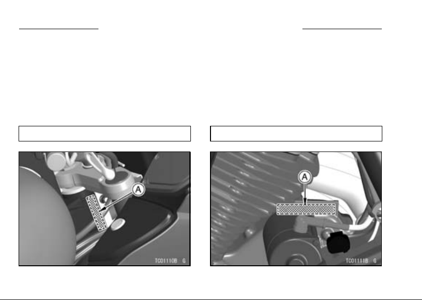
Frame No.
A. Frame Number
Engine No.
A. Engine Number
LOCATION OF PARTS
LOCATION OF PARTS 15
1. Clutch Lever
2. Clutch Fluid
Reservoir
3. Front Speakers
4. Meter Unit
5. Audio Unit
6. B rake Fluid Reservoir
(Front)
7. Front Brake Lever
8. T hrottle Grip
9. R igh t Handlebar
Switches
10. Fairing Pockets
11. Fuel Tank Cap
12. Ignition Switch
13. Left Handlebar
Switches
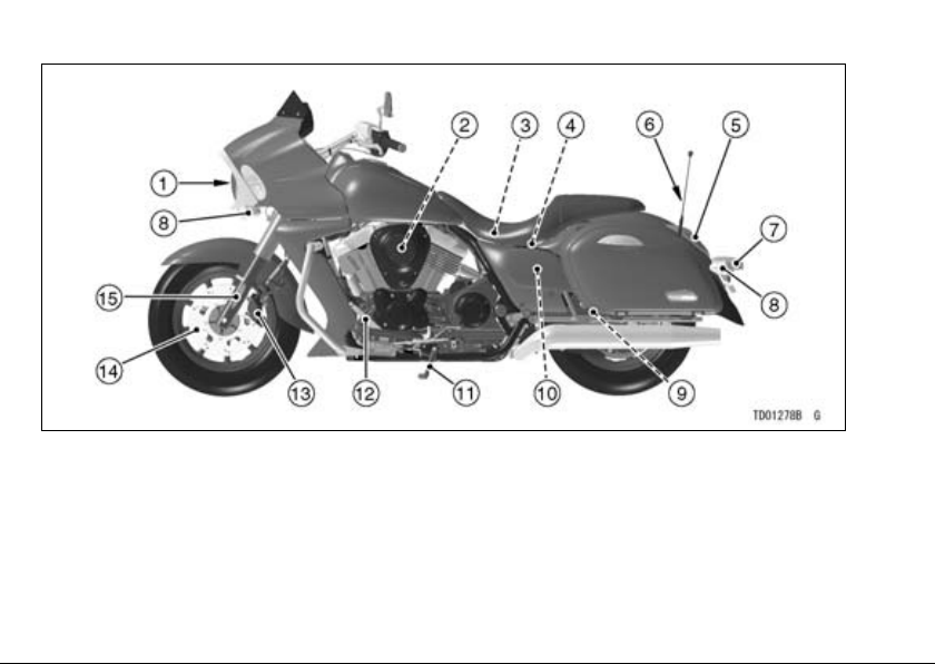
16 LOCATION OF PARTS
1. Headlight
2. Air Cleaner Element
3. Fuse Box
4. Battery
5. Tail/Brake Light
6. Antenna
7. Licence Plate Light
8. Turn Signal Light
9. Drive Belt
10. Coolant Reserve Tank
11. Side S tan d
12. Shift Pedal
13. B rake Caliper
14. B rake Disc
15. F ron t Fork
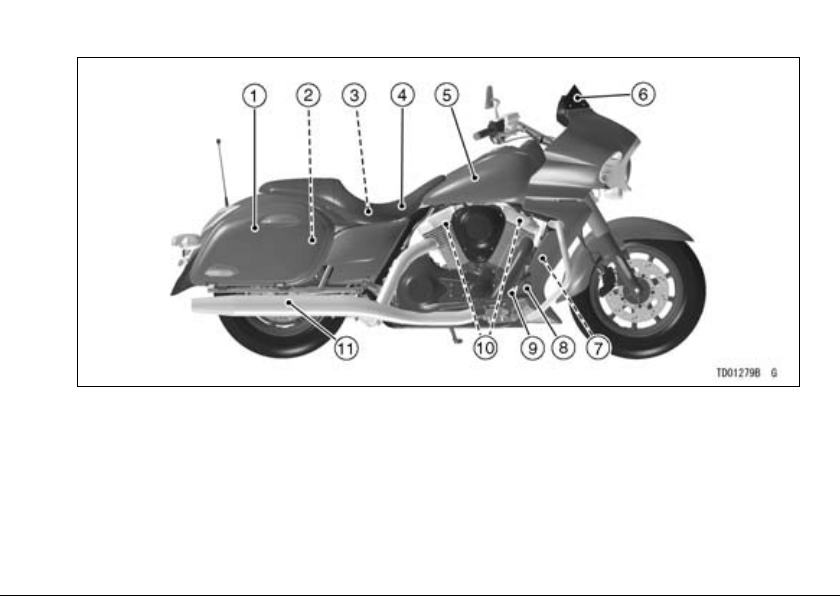
LOCATION OF PARTS 17
1. Saddlebag
2. Rear Shock Absorber
3. Tool Kit
4. Seat
5. Fuel Tank
6. D e flector
7. B rake Fluid Reservoir
(Rear)
8. R ear Brake Pedal
9. Re ar Brake Light
Switch
10. Spark Plugs
11. Muffler
18 LOADING AND ACCESSORIES INFORMATION
LOADING AND ACCESSORIES INFORMATION
WARNING
Incorrect loading, improper installation or use of accessories,
or modification of your motorcycle may result in an unsafe riding
condition. Before you ride the
motorcycle,makesureitisnot
overloaded and that you have
followed these instructions.
With the exception of genuine
Kawasaki Parts and A ccess ories ,
Kawasaki has no control o ver the
design or application of a ccessories.
In some cases, improper installation
or use of accessories, or motorcycle
modification, will void the motorcycle
warranty, can negatively affect performance, and can even be illegal.
In selecting and using a ccessories,
and in loading the motorcycle, you are
personally responsible for your own
safety and the safety of other persons
involved.
NOTE
Kawasaki Parts and Accessories
○
have been specially designed for
use on Kawasaki motorcycles. We
strongly recommend that all parts
andaccessoriesyouaddtoyour
motorcycle be genuine Kawasaki
components.
Because a motorcycle is sensitive to
changes in weight and aerodynamic
forces, you must take extreme care
in carrying cargo, passengers and/or
in the fitting of additional accessories.

LOADING AND ACCESSORIES INFORMATION 19
The following general guidelines have
been prepared to assist you in making
your determinations.
1. Any passenger should be thoroughly familiar with motorcycle operation. The passenger can affect
control of the motorcycle by improper positioning during cornering
and sudden movements. It is important that the passenger sit still while
the motorcycle is in motion and not
interfere with the operation of the
motorcycle. Do not carry animals
on your motorcycle.
2. You should instruct any passenger
before riding to keep his feet on the
passenger footpegs and hold on to
the operator or seat strap. Do not
carry a passenger unless he or she
is tall enough to reach the footpegs
and footpegs are provided.
3. All baggage should be carried as
low as possible to reduce the effect
on the motorcycle center of gravity.
Baggage weight should also be distributed equally on both sides of the
motorcycle. Avoid carrying baggage
that extends beyond the rear of the
motorcycle.
4. Baggage should be securely attached. Make sure that the baggage
will not move around while you are
riding. Recheck baggage security
as often as possible (not while the
motorcycle is in motion) and adjust
as necessary.
5. Do not carry heavy or bulky items on
a luggage rack. They are designed
for light items, and overloading can
affect handling due to changes in
weight distribution and aerodynamic
forces.

20 LOADING AND ACCESSORIES INFORMATION
6. Do not install accessories or carry
baggage that impairs the performance of the motorcycle. Make
sure that you have not adversely
affected any lighting components,
road clearance, banking capability
(i.e., lean angle), control operation,
wheel travel, front fork movement,
or any other aspect of the motorcycle’s operation.
7. Weight attached to the handlebar or
front fork will increase the mass of
thesteeringassemblyandcanresult in an unsafe riding condition.
8. Fairings, deflector, backrests, and
other large items have the cap ability
of adversely affecting stability and
handling of the motorcycle, not only
because of their weight, but also due
to the aerodynamic forces acting on
these surfaces while the motorcycle
is in operation. Poorly designed or
installeditemscanresultinanunsafe riding condition.
9. This motorcycle was not intended
to be equipped with a sidecar or to
be used to tow any trailer or other
vehicle. Kawasaki does not manufacture sidecars or trailers for motorcycles and cannot predict the effects of such accessories on handling or stability, but can only warn
thattheeffectscanbeadverseand
that Kawasaki cannot assume responsibility for the results of such
unintended use of the motorcycle.
Furthermore, any adverse effects on
motorcycle components caused by
the use of such accessories will not
be remedied under warranty.
Maximum Load
Weight of rider, passenger, baggage,
and accessories must not exceed 180 kg
(397 lb).
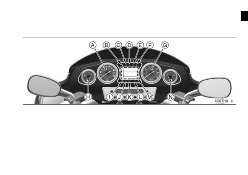
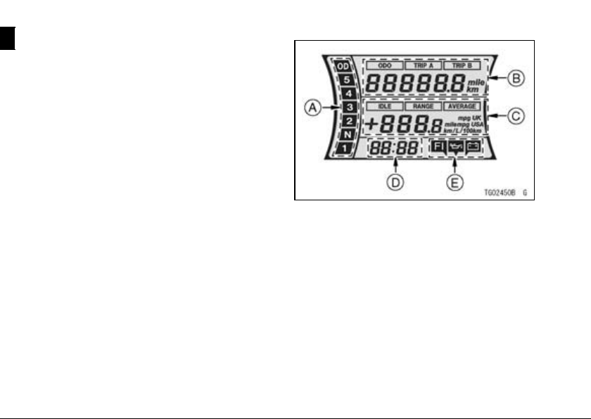
Meter Instruments
GENERAL INFORMATION 21
GENERAL INFORMATION
A. Speedometer
B. Fuel Level Warning
Indicator Light
C. Left Turn Signal
Indicator Light
D. Neutral Indicator
Light
E. Right Turn Signal
Indicator Light
F. High Beam Indicator
Light
G. Tachometer
H. Fuel Level Gauge
I. K -ACT ABS Indicator
Light (only on
equipped model)
J. Ele ctron ic Cruise
Control Indicator
Light
K. Electronic Cruise
Control Set Indicator
Light
L. Warning Indicator
Light
M. Multifunction Meter
N. Coolant Temperature
Gauge
22 GENERAL INFORMATION
Speedometer and Tachometer
The needle of the speedometer and
tachometer momentarily sweeps from
the minimum to maximum and back
to minimum when the ignition key is
turned to “ON”. This checks the operation of the meter needles. So if they do
not operate correctly, have the function
checked by an authorized Kawasaki
dealer.
The speedometer shows the speed
of the vehicle.
The tachometer shows the engine
speed in revolutions per minute (r/min,
rpm). On the right side of the tachometer face is a portion called the “red
zone”. Engine r/ min (rpm ) in the
red zone is above maximum recommended engine speed and is also
above the range for good performance.
NOTICE
Engine r/min (rpm) should not
be allowed to enter the red zone;
operation in the red zone will
overstress the engine and may
cause serious engine damage.
Fuel Level Gauge
The fuel level gauge shows the
amount of fuel in the fuel tank. When
the needle comes near the E (empty)
position, refuel at the earliest opportunity. When vehicle stands with Side
Stand, Fuel Level Indicator Light/Fuel
Level Gauge cannot show the amount
of fuel in the fuel tank exactly. Stand
upright the vehicle to check the fuel
level.
NOTE
If the motorcycle is held horizontal
○
while refueling, the fuel level gauge
GENERAL INFORMATION 23
may not show the rightmost needle
on the gauge.
Coolant Temperature Gauge
This gauge shows the temperature of
coolant. Ordinarily, the needle should
stay within the white zone. If the needle
reaches the red zone, stop the engine
and check the coolant level in the reserve tank after the engine cools down.
NOTICE
Do not let the engine continue
running when the coolant tem-
perature gauge shows “H”. Pro-
longed engine operation will
result in severe engine damage
from overheating.
Meter Unit Sw itch
Meter unit switch is loc ated on the
right handlebar switches. Select the
meter unit switch function by pushing
the knob of the meter unit switch.
“Push the S button” means to push the
knob.
“Push the MODE-A switch” means to
push the knob to the left.
“Push the MODE-B switch” means to
push the knob to the right.
A. Meter Unit Switch
B. “S” Button
C. “MODE-A” Switch
D. “MODE-B” Switch
E. Knob
24 GENERAL INFORMATION
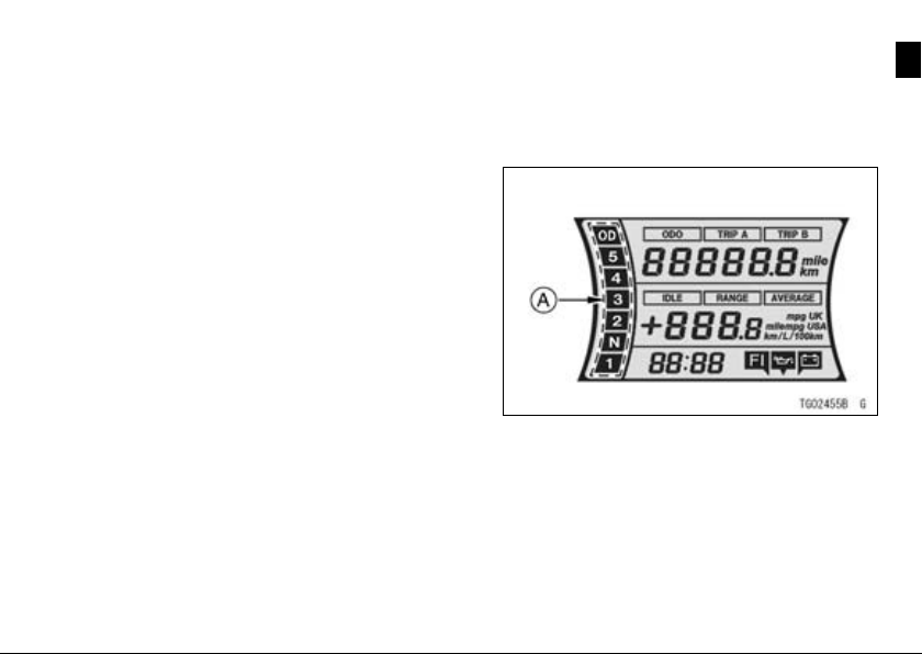
Multifunction Meter
The multifunction meter displays the
following functions: oil pressure warning symbol, battery warning symbol,
fuel injection warning symbol, o dometer, trip meters (TRIP A, TRIP B), clock,
average mileage, cruising range, idle
speed and gear positions. When the ignition key is turned to “ON”, all the LCD
segments are displayed for three seconds, then, depending on the mode selected, the clock or meters operate normally.
A. Gear Position
B. Odometer/Trip Meters (TRIP A, TRIP B)
C. Cruising Range/Average Mileage/Idle
Speed
D. Clock
E. Warning Symbols Indicato r
GENERAL INFORMATION 25
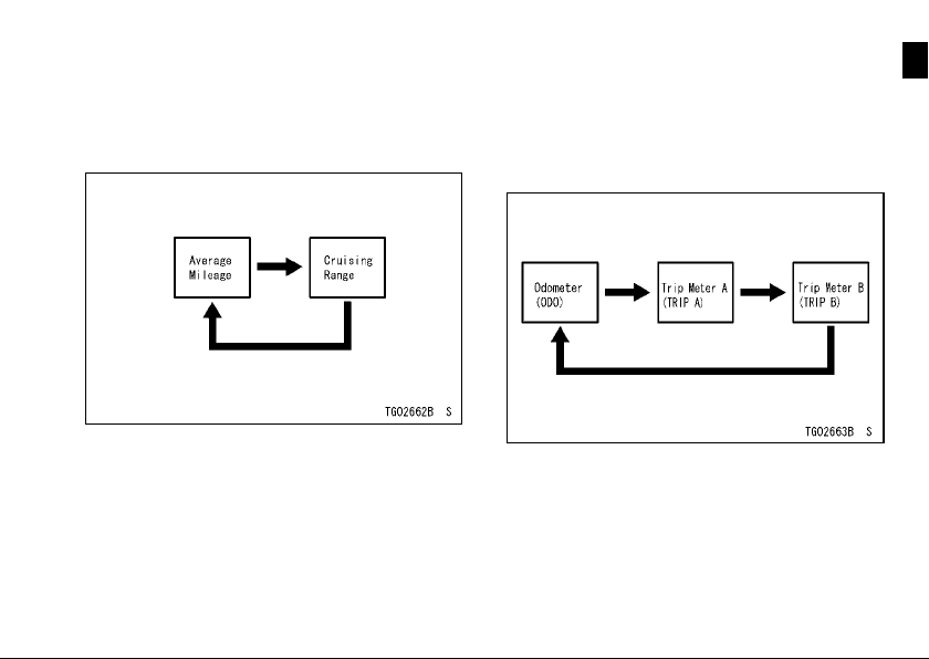
Pushing the “MODE-A” switch shifts
the display in the multifunction meter
through the following two modes: cruising range and average mileage.
Pushing the “MODE-B” switch shifts
the display in the multifunction meter
through the following three modes:
odometer, trip meter A and trip meter
B.
Odometer (ODO)-
Pushthe“MODE-B”switchtodisplay
•
the ODO.
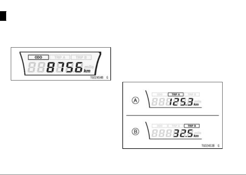
26 GENERAL INFORMATION
The ODO shows the total distance in
•
kilometers (km) or miles (mile) that
the motorcycle has run. This meter
cannot be reset.
NOTE
The data are maintained ev en if the
○
battery is disconnected.
When the figures come to 999999,
○
the display is locked.
The measurement unit of the odome-
○
ter can be changed by referring to the
“Setting Menu” in this section.
Trip Meters (TRIP A, TRIP B) –
The trip meters show the distance in
•
kilometers (km) or miles (mile) traveled since they were last reset to
zero.
TRIP A: 0.0 ∼ 9999.9
TRIP B: 0.0 ∼ 999.9
Push the “MODE-B” switch to display
•
the TRIP A o r TRIP B.
A. Trip A
B. Trip B
GENERAL INFORMATION 27
Pushthe“MODE-B”switchtodisplay
•
theTRIPAorTRIPB.
Push the “MODE-B” switch and hold
•
it there.
After two seconds, the display turns
•
to 0.0 and then starts counting when
themotorcycleisoperated. Themeter counts until it is reset.
NOTE
Thedataaremaintainedbytheback
○
-up power even if the ignition key is
turned to “OFF”.
When the trip meter display reaches
○
9999.9 (TRIP A) or 999.9 (TRIP B)
while running, the meter is reset to
0.0 and continues counting.
When the battery is disconnected,
○
the meter display is reset to 0.0.
Themeasurementunitofthetripme-
○
ters can be changed by referring to
the “Setting Menu” in this section.
Gear Position Indicator-
The gear position indicator shows the
corresponding gear position where the
transmission is shifted.
A. Gear Position Indicator
1: When the transmission is in 1st
gear, “1” is displayed.
2: When the transmission is in 2nd
gear, “2” is displayed.
3: When the transmission is in 3rd
gear, “3” is displayed.
28 GENERAL INFORMATION
4: When the transmission is in 4th
gear, “4” is displayed.
5:
When the transmission is in 5th
gear, “5” is displayed.
OD: When the transmission is in Over
Drive gear, “OD” is displayed.
Clock -
The hour adjusting mode and minute
adjusting mode can be shifted by referring to the “Setting Menu” in this section.
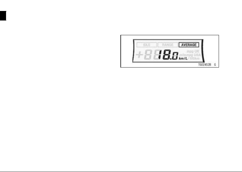
Average Mileage (AVERAGE)-
This display shows the average
mileage by numerical value, and indicates the average fuel consumption
counted from th e start of m ea su ring to
the present time.
Push the “MODE-A” switch to display
•
the average mileage.
NOTE
The data are maintained by backup
○
power even if the ignition key is
turned off.
The measurement unit of mileage
○
can be changed by referring to the
“Setting Menu” item in this section.
Push the “MODE-A” switch for more
○
than two seconds while the average
mileage is displayed, and the average mileage is reset to “– –. –”.
GENERAL INFORMATION 29
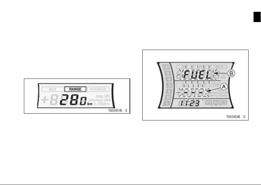
Cruising Range (RANGE)-
This display shows the cruising range
by numerical value and indicates the
cruising range from the remaining fuel
in the fuel tank. This cruising range
display is renewed every 10 seconds.
Pushthe“MODE-A”switchtodisplay
•
the cruising range.
When the fuel warning message
•
“FUEL” blinks in the digital meter, the
cruising range value also blinks “- -
-”.
A.“---”Blinks
B. “FUEL” Blinks
NOTE
The measurement unit of the cruising
○
range can be changed by referring to
the “Setting Menu” in this section.
 Loading...