

Kawasaki VN1500 (1987-1999) User Manual [ru]
Kawasaki vN1500
Motorcycle
Service Manual
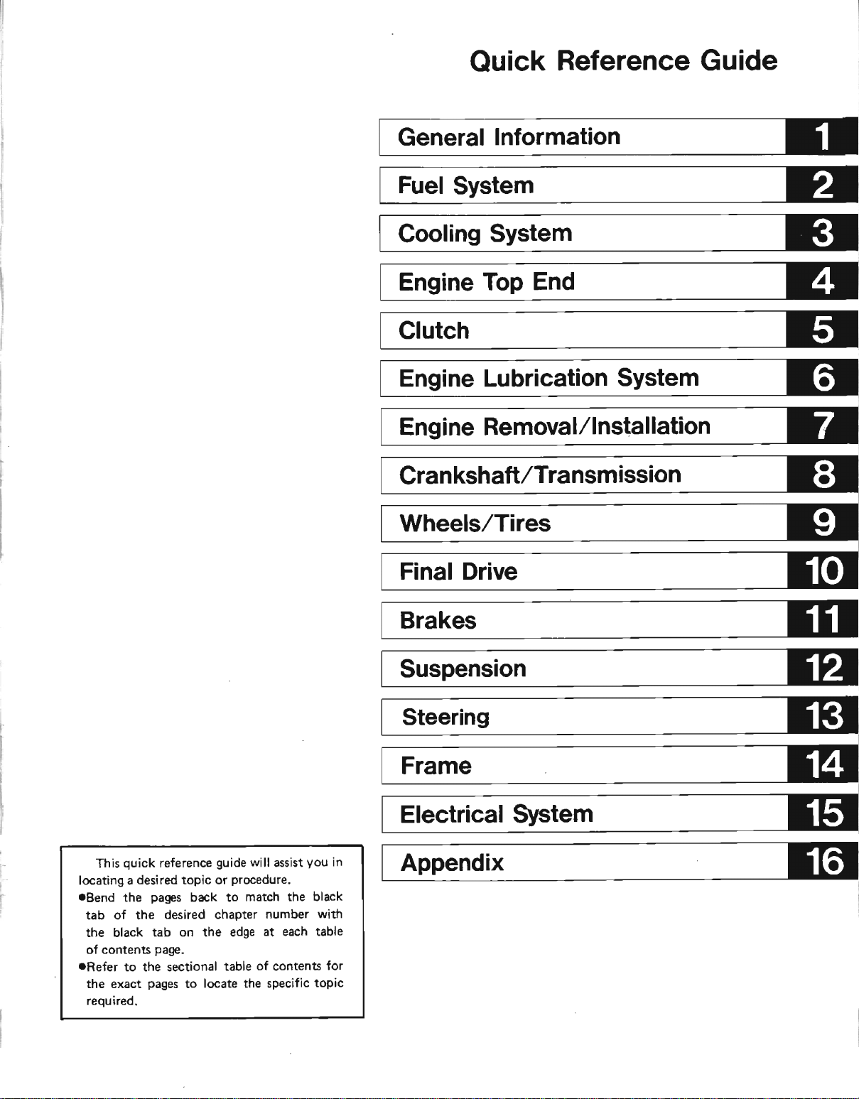
Quick
Reference
Guide
quick
This
locating a desired topic
.Bend
tab of the
the black tab
oi contents
aRefer
exact
the
required,
reference
pages
the
to the sectional
back to
desired chapter
on the edge at
page.
pages
locate the specific topic
to
guide
will assist
procedure.
or
match the black
number with
each table
table of contents
you
in
for
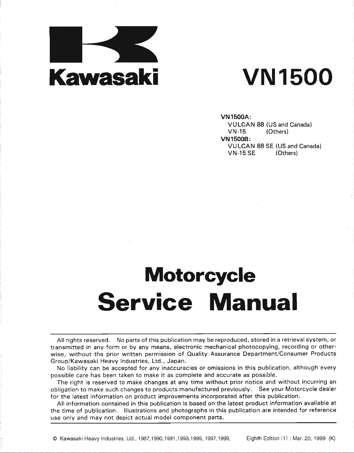
Kawasaki
vN1500
VNl5OOA:
VULCAN 88
VN-15
VNlSOOB:
VU LCAN 88 SE
VN-15
SE
(US
and
Canada)
(Othersl
(US
and
(Othersl
Canada)
Service
All rights
transmitted
wise, without the
Group/Kawasaki Heavy
No liability can be accepted for any
possible
The
obligation
for the latest
All information contained
the time of
use only and
@ Kawasaki Heavy
reserved. No
in any
care has been
is
right
reserved
to make
information
publication.
may not
Industries,
form
prior
such
parts
of this
or by any
written
Industries, Ltd., Japan.
taken
to make changes at any time
changes to
on
lllustrations and
depict
Ltd., 1 987, 1 990, 1 991, 1 993, 1 995,
permission
make it as complete and accurate as
to
product
in this
actual model component
Motorcycle
Manual
publication
means, electronic mechanical
inaccuracies or omissions in this
products
improvements
publication
photographs
may be reproduced, stored
of Ouality
manufactured
is based on the latest
Assurance Department/Consumer
without
incorporated
in this
parts.
1 997, 1
prior
previously.
publication
999,
photocopying,
notice and
after
product
Eighth Edition
in a retrieval system, or
publication,
possible.
without incurring an
your
See
publication.
this
information available
intended for
are
(1)
recording
although
Motorcycle dealer
: N/ar.20, 1999
or otherProducts
every
referencs
at
(K)
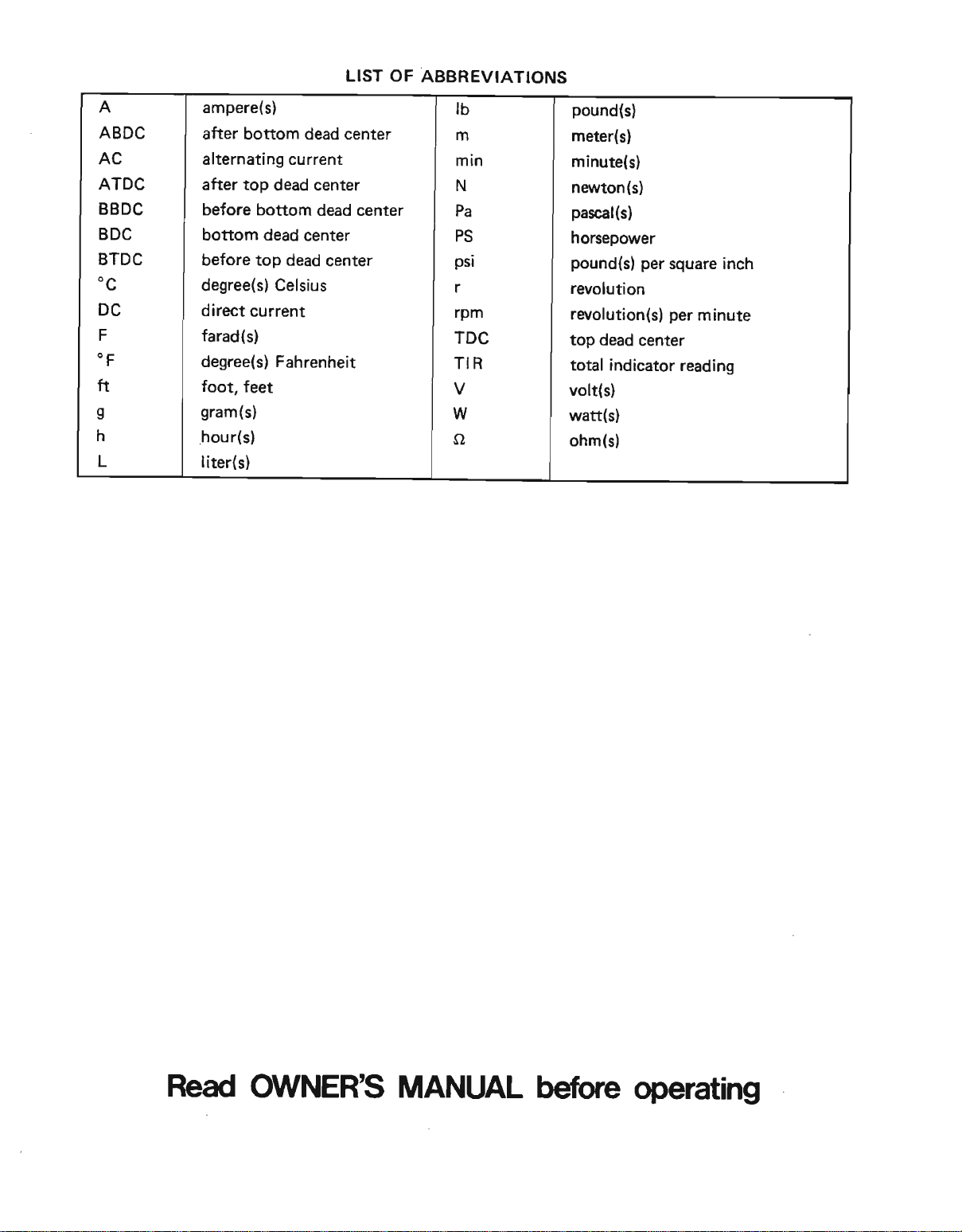
LIST OF ABBREVIATIONS
A
ABDC
AC
ATDC
BBDC
BDC
BTDC
"c
DC
F
.F
ft
s
h
L
ampere{s}
after bottom
alternating current
after
top dead center
before
boftom
before top
degree(s)
direct current
farad
degree(sl Fahrenheit
foot, feet
gram{s)
hour(sl
liter(s)
bottom
dead center
dead center
Celsius
(s)
dead
dead
center
center
tb
m
min
N
Pa
PS
psi
rpm
TDC
TIR
W
o
pound(sl
meter{s}
minute(s)
naryton(sl
pascal(s)
horseporer
pound(s)
rwolution
revolution(sl
top
total indicator r€ading
volt{s)
watt(s)
ohm(s)
per
square
per
dead center
inch
minute
Read
O,I/NER'S MANI At
before
operating
EMISSION CONTBOL
INFORMATION
protect
To
emission
ulations of the United States Environmenal
sources Board. Additionally,
system
on vehicles
1.
2. Exhaust
3. Evaporative
what
{3}
Crankcase
This system eliminates the release of
the
the
burned along with
This system
exhaust of this
been
pollutant
Vapors
phere.
in a canister when the engine is stopped.
returned to the
The
Clean
is
commonly
"Sec.
(3)(A)
(3XB)
the environment in
(1)
and exhaust emission
in compliance with applicable
sold in
vapors
engine is
Emission
carefully
203(a)
for
installed on or in a motor vehicle or motor vehicle
regulations under
or for any manufacturer or dealer knowingly
such device or element of design after such sale and delivery to the
purchaser.
for
trading motor vehicles or motor vehicle engines, or who operates a
vehicles
design installed
with regulations under this title following its sale and delivery to the
ourchaser..."
California
Emission Control System
routed through
are
operating,
Control
reduces
motorcycle.
designed
levels.
Emission Control'System
caused by
Instead,
Air Act, which is the Fede€l law
any
any
fuel vapors
fuel tank.
referred to
The follorving acts and
person
person
knowingly to remove or
the vapors
the fuel
System
the amount of
fuel
waporation in the fuel system are
to
this title
engaged in the business of repairing, servicing,
on or
which we
(2)
Kawasaki
only.
an oil separator
and air supplied
The
and constructed
are routed into
as the
remove or render ihoperative any device
Act's
the
prior
in a motor vehicle
all live, Kawasaki
control
has
incorporated
regulations
crankcase vapors
are drawn
pollutants
fuel
and ignition
to encrre an
Liquid
"tampering
causing
its
to
render
has incorporated crankcase
compliance with applicable
systems
Protection
into
by the
the
covering
thereof
sale and delivery
in
Agency
evaporative
an
the California
of
into the
to the
discharged
running engine
fuel is caught
or
intake side of the engine.
combustion
carburetion
systems
efficient
motor
provisions."
are
remove or
to
inoperative any device or
motor vehicle engine in compliance
chamber, where they are
system.
into
of this
not vented into the atmos
by a vapor separator and
vehicle
prohibited...
engine in compliance with
to the ultimate
reg-
Re
and California
emission control
Air Resources Board
atmosphere. Instead,
the atmosphere by
motorcycle have
engine with loriv exhaust
to be burned, or stored
pollution,
or element of design
render inoperative any
selling, leasing, or
Air
While
the
contains
purchaser,
ultimate
fleet of motor
element of
ultimate
(Continued
on next
page.l
phrase
. The
generally
1. Tampe ng
vices
2. Tampering
a. Maladjustment
b. use
durability
c. Addition
standards.
Permanently
d.
element
"
remove
interyreted
or
elements
of replacement
of design
or rendet
as
does not
of design in
could include
of vehicle
of the motorcycle.
of components
removing,
inoperative
follows
include
parts
of
:
the
:
components
or accessories
ot accessories
disconnecting,
the emission
NOTE
any device
temporary
order
perform
to
such that
control
or element
removal
which
that result
or rendering
systems.
or rendering
maintenance-
the emission
adversely
of
design
inoperative
standards
affect
in the vehicte
inoperative
the
any component
,,
has been
of
are exceeded.
pedotmance
exceeding
the
de-
or
or
WE RECOMMEND
FEDERAL
PENALTIES
LAW,
NOT
TAMPEBING
Federal
rendering
replacement,
purpose
th€_.
while it
been
is in use,
remored
prohibits
law
inoperative
of any
of
noise control
or
or rendered
THAT
ALL
DEALERS
THE VIOLATION
EXCEEDING
WITII
the following
by any
darice
(21
person
or element
the use
inoperative
NOISE
prior
of the
to
$1O,OOO
CONTBOL
acts
other
of
i6
vehicle
by
any
OBSERVE
OF WHICH
PER
VIOLATION.
SYSTEM
or the causing
than for
purposes
THESE
IS PUNISHABLE
PBOHIBITED
thereof:
of maintenance,
design incorporated
sale or
deliriery
after
grch
to the
device or
pervrn.
PROVISIONS
(1)
The
into
any neur
ultimate
element
OF
BY
CIVIL
removal or
repair,
vehicle'for
purchaser
o:f a".id
h.,
or
or
_Among
.
R.eplacem€nt
pltance
oRemoval
.Removal
rModifications
if
such
those
wtth Fedeftrl
of
the
of the
modifications
pre$med
asts
of_
the original
regulations.
muffler(s)
air
box or air
to the
muffrer(s)
result
to constitute
exhaust
or
any internal
box
cover.
or
air intake
in increased
tampering
system
portion
noise
tevLis.
are
the acts listed
or mriffler
of the
system
muffler(s).
by cutting,
-' --
below:
with a component
dri ing,
or
other
not
in
com-
means
Foreword
manual is designed
This
trained
However,
information
who desires
tenance
of
workshop
order to
satisfactorily,
ficient experience
the work, all adjustments,
repair should be carried out only by
mechanics.
to avoid costly mistakes, read the
oughly
before starting work, and then do
carefully in a clean area. Whenwer
tools or equipment are specified,
makeshift tools
urements can
struments are used,
tools
especially, we recommend
scheduled maintenance
ance
maintenance
in
warranty.
cycre:
oFollow
Service Manual,
.Be
maintenance.
eUse proper
cycle
that are
motorcycles
Manual.
are listed in the Pans
rFollow
fully. Don't
rRemember
tenance and repair with
pafts
mechanics in a
it contains enough
make it useful to the owner
to
perform
to
and repair work.
mechanics, the
procedures
carry
In order to
familiarize
may
For the
with
accordance with this manual may void
get
To
alert for
parts.
installed.
perform
adversely affect safe
duration of
this service manual,
or
the
the Periodic Maintenance
tools and
Special tools,
necessary
are
Genuine
procedures
the
take
to keep complete records of
proper
out
Whenever
or doubts
yourself
equipment. Precision
or
only be
and the use of substitute
repair
longest
problems
introduced
pafts provided
shortcuts.
primarily
properly
his
own basic
A
use of tools, and
must be
maintenance
the owner
his
maintenance,
the work efficiently
with the
made
be
procedure
life out of
genuine
when
Catalog.
if the
your
warranty
that all repairs
performed
and non-scheduled
gauges,
servicing
by the Special Tool
in
this
dates and any
for use
equipped
detail and basic
knowledge
basic
understood
and repair
has
ability to
qualified
text, thor-
procedures
the work
do not
proper
operation.
in accord-
Any owner
performed
not
your
Chart in the
Kawasaki Motor-
and testers
Kawasaki
as spare
manual car+
by
shop.
main-
in
insuf-
do
and
and
special
use
meas-
in-
period,
and
the
Motor-
parts
main-
new
How
product
became the
for
disassembly
chapter,
the
their
olvn
the General
gives
operations,
example,
first. The chart tells
clean
Reference
chapter.
first
section.
CAUTION
Always
practices.
oThis
tions
followed, could result in
loss of life.
oThis
tions or
served, could result in damage to or destruction of equipment.
addition
will help
information.
Use this
to
preparing
ln
into its
panicular
a
Ouick Reference Guide
The
produst,s
chapters. Each
comprehensive
Periodic Maintenance Chan
The
a time schedule
you
lf
go
and
Then.
page
Whenaner
follow safe
waming
or
caution symbol identifies special instruc-
This manual contains
to
Manual
manual, we divided
this
major systems,
manual's chapters.
system
and
systems and
Information chapter.
want spark
to the Periodic Maintenance Chart
gap
the
Guide to
use
of the chapter to
you
symbols,
rymbol
procedures
procedures
WARNING
you
distinguish
from adiustment
inspection
chapter
Table of Gontents.
for required
plug
lou
plug.
locate
the Table of Gontents
see these
operating
Next, use
the
heed
identifies special instruc-
which, if not correctly
whicfi, if
five
and CAUTION) which
These
All information
is located in a single
shows
assisB in
in turn has its
information,
hovv frequently to
Electrical
find
the Spark
WARN ING
their instructions!
and maintenance
perconal
not strictly ob-
more
different types of
systems
through
you
locating
is located in
The chart
maintenance
the
System
iniury. or
symbols
the
all
Ouick
on
Plug
and
of
for
the
(in
oThis
ular
venient
NOTE
note symbol indicates
interest for more
operation.
efficient and con-
pointr
of
partic-
.Indicates a procedural
done.
olndicates a procedural
the work
It also
CAUTION,
*
lndicates
take based
inspection in
it follows.
*lndicates
astion
conditional
of the
precedes
NOTE.
or
a conditional step
on the results of
the
a conditional
to take bas€d upon
it follows.
step
sub-step or
procedural
the text of a WARNING,
procedural
step
$b-step
work
or
how
step it follows.
what
or
the test or
step or sub-step
the results
to be
to do
action
or what
to
of the
ln most
tion of
Table
will find
require
or a locking
the system components
of
Contents. In
the instructions
qecified
chapters an.exploded
these illustrations
indicating
tightening
agent
during
assembly.
viqlv illustra-
torque, oil,
follorvs
which
parts
grease
the
you
GENERAL
INFORMATION T.1
General
Table
Before
Model
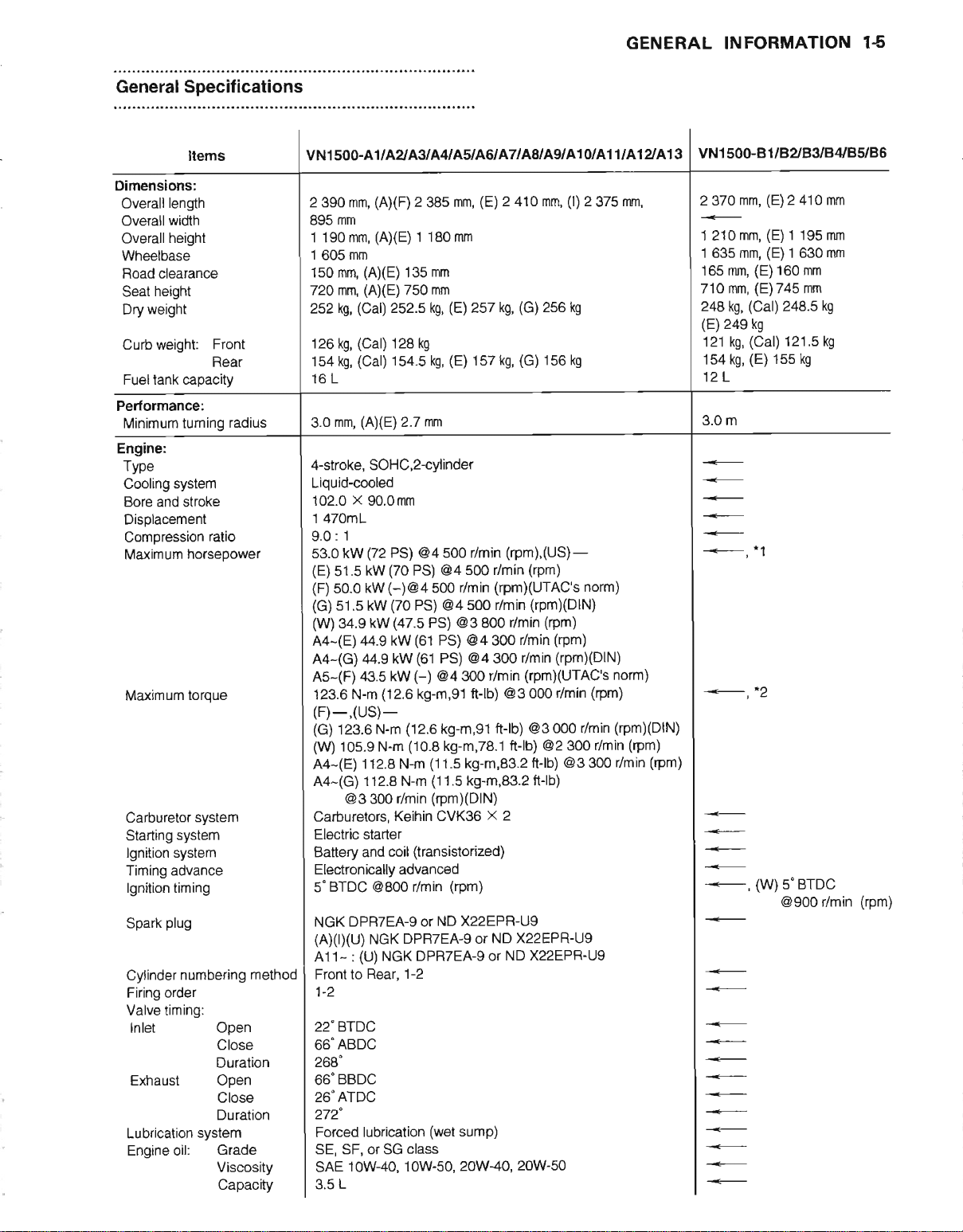
General Specifications.
Periodic
Torque and Locking Agent
Cable. Wire and
Servicing
ldentification
maintenance
. .
Hose Routing.
. . . 14
, . .
Chart.
Information
of
Contents
1-2
1-5
1-7
1€
1-12
1.2
GENERAL
INFORMATION
Before
unnecessary
included
knowledge
Especially
(1)
(2)
(3)
(4)
(5)
(5)
(7)
(8)
(9)
.
(10)
(1
1) Press
(12)
Serwicing
Before
starting
work.
wherever
is also
note
Dirt
Before removal
work
as
an abrasive
part,
clean
Battery Ground
Remove
motorcycle.
prevents:
This
sparks
Dans.
Installation,
has installation
during removal
mark
TighteningSequence
tighten them
part
all of
in this
Torque
lead
Force
especially
tapping
(particularly
Edses
with
High- Flash
available
directions
Gasket,
should
Liquid
used.
example
(Blue).
or inner
Ball
needle
with
at electrical
Generally,
and record
Generally.
and/or
them by
Service
When
torque
to serious
Common
is
Watch
A high-flash point
Do not
Follow
A
Do
for
gloves
in
regarding
O-Ring
reuse a gasket
be free
Gasket,
manufacturer's
Apply
of a non-permanent
part
installed
circumference
Bearing
not remove
bearings
the marked
to
service
Photographs,
necessary.
required
the
off any
ground
the
When
(a)
Assemblv
installation
or assembly
or
when insulling a part
to a
causing
about a
Manual.
values
damage.
sense should dictate
difficult
necessary,
for
the removal
sharp
piece
or
a
Point
North America
of foreign
Non-Permanent
sparingly'
and Needle
that
side
a motorcycle,
Nevertheless,
for
successful
following;
and disassembly,
and shorten
dust
or metal filings.
(-)
installing,.connect
possibility
the
connections
or assembly
procedures,
disassembly
the
locations
snug fit.
gas
to
edges,
Sotvent
the use
using
a ball bearing
were removed
facing
Then
or oil leakage.
quaner
the bolts,
given
are
Use
remove
tap lightly
of
especially
of thick
solvent
is
Stoddard
of any
or O-ring
matter
directions
Excessive
press
a
so that it
Bearing
out applying
careful reading
diagrams,
the life
lead
from
of accidentally
which
so
and
tighten
turn and
nuts,
in this
good quality,
a
how
or install,
using a wooden
screws held
cloth when
is recommended
and
Locking
amounts
locking
or
drivet
will
or a needle
with
notes,
even
work.
clean
the
of
the motorcycle.
the battery
positive
the
will
occur when
is the reverse
follow
they can
routing
with
during
solvent.
once it
perfectly
for
go
be installed
as much
several
them
Conversely
then remove
or screws
Service
much force
stop
by a locking
major
litting
solvent
has
Agent
cleaning
may
agent
commonly
such as a wheel
place
into
bearing unless
new
ones,
pressure
reliable
and
smooth to
of the
cautions,
a detailed
motorcycle.
turning
them.
evenly in
must
Manual,
is necessary
examine
or
the
to
(generic
been in
and
block
smoothly.
evenly with
account
before
(+)
lead
of removal
Note
or assembled
possibte.
as
bolts, nuB,
when loosening
them. Where
be
use
torque wrench,
plastic-faced
ageno in
engine
engine
reduce fire
name).
avoid
preparing
engine
available
bearing,
removal generally
as
applicable
warnings,
has limitations,
Any
dirt
For
the same
performing
firs! then
the engine
they are
parts
a
cross
tightened in
what may
disassembly
service.
it is
disconnected.
or
disassembly.
locations
or
screws,
pattern.
there
them. Either
in assembly
mallet
order
or turning
danger.
Always
The
oil or
compression
surfaces
passages
oil
in
North
should
absolutely
a suitable
section
and
enGring
any
the negative
over while
in
the
the ordlr
be
to avoid
and assembly.
it over.
mating
damages
is recommended
detailed
the
ieason,
disassembly
partially
But
ani
cable,
the
same way.
start them
This
is to
bolts,
nuts,
is a
tightening
and
too little
and disassembly.
causing
Use
an impact
damaging
A commefcial
follow
driver.
manufacturer
surfaces
where
these
and
cause
America
first
be coated
necessary.
Only
beirings.
descriptions
a
certai;
engine
defore
1-j
1c1
or too much
the
leaks.
is Loctite
amount
or other
installing
operations
tead
to
disassembled. (b)
damage
if
this
Service Manual
wire, and
all
avoid
or screws. first
sequence indication
irethod
problem.
protect
solvent
compounds
serious
with
Replace any
pr&
hose
preferable
lt is
in their
distortion
inoicated.
lf
a
driver
the
screw
your
and container
around
damage.
Lock,n
oil on tts
Install
on the race
to eliminate
have
been
of
basic
parts
will
a new
on
the
the battery.
to electrical
routing
6
holes
and
of the
loosen
rorque
commonly
the
may
pan
seems
Whenever
for
screws
heads.
hands
gasket
will
be
An
Seal
outer
ball
or
bearings
that
GENERAL
INFORMATION 1-3
forms the
the balls or needles and races, and
on
bearing until
(13)
Oil Seal
Replace
When
should be
{ace of the seal
temperature
(14)
Circlip.
Replace any circlips, retaining rings. and cotter
weakens
them only enough to
(15)
Lubrication
Engine
surfaces have an adequate
should be applied to any
be cleaned off. Deterioiated
Don't
applications
makes reference to
parts.
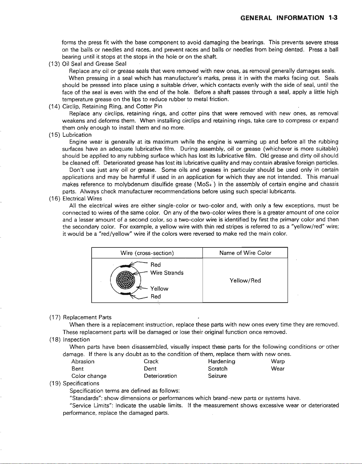
(16)
Electrical
All the electrical wires are either single-color or two-color and,
connected to wires of the same color. On any of the two-color
and
the secondary color.
woufd
it
press
fit with the base component to avoid damaging the bearings.
prevent
it stops at the stops
and Grease Seal
grease
oil
any
pressing
pressed
Retaining Ring. and Cotter Pin
and
wear
use
Always check
Wires
a lesser amount of a second color, so a two-color wire is identified by
be
or
in a seal which has manufacture/s marks,
place
into
is
grease
deforms them. When installing circlips and retaining
is
iust
and may be harmful if used in an application for which they are
"redlvellow"
a
with the end of the hole.
even
on the lips to reduce rubber to
install them
generally
rubbing surface which has lost its lubricative film.
any oil or
molybdenum
manufacturer recommendations
For
example, a
in
the hole or on the shaft.
seals that were
a suitable drivet which contacts evenly
using
no more.
and
its maximum while
at
lubricative film. During assembly, oil or
grease
wire il the colors were reversed to make red the main color.
has lost is lubricative
grease.
Some oils and
disulfide
yellow
races and balls or needles
removed
Before
metal
grease (MoS"
wire with
new
with
press
a shaft
friction.
pins
that
the engine
quality
greases
betore
thin
in
in the assembly ol certain engine and
)
using such special lubricants.
red stripes is refened to as a
prevents
This
from
being dented. Press a ball
ones, as
were removed with new ones,
is warming up
and may contain abrasive
particular
wires there is a
removal
it
with
in
passes
through a seal, apply a
rings,
grease (whichever
with
generally
marks facing out.
the
with
the side of seal, until the
take care
Old
should
only a
first the
to compress or expand
before all the
and
grease
be
used
not intended. This manual
few exceptions, must be
greater
amount of one
primary
severe stress
damages
is more
and dirty oil should
foreign
only in certain
color and then
"yellow/red"
seals.
Seals
little high
removal
as
rubbing
suitable)
panicles.
chassis
color
wire;
Wire
(17)
Replacement Parts
When there is a replacement instruction, replace these
These replacement
(18)
Inspection
When
damage. lf there is any doubt as to
(19)
Specifications
performance,
parts
Abrasion
Bent
Color
change
SDecification terms are defined as
"Standards":
"Service
Limits": indicate the usable
parts
have
been disassembled,
show dimensions or
replace the damaged
(cross-section)
Red
'
Wire Strands
Yellow
Red
will
be damaged
the
Crack
Dent
Deterioration
follows:
performances
parts.
or lose their
visually inspect
condition
limits. lf
of them, replace them with new ones.
which
measurement
the
Name of Wire Color
Yellow/Red
parts
original
these
new
with
function once removed.
parts
ones every time they
for the following conditions or-other
Hardening Warp
Scratch
Wear
Seizure
brand-new
parts
or systems
shows excessive
are removed.
have.
wear
or deteriorated
14
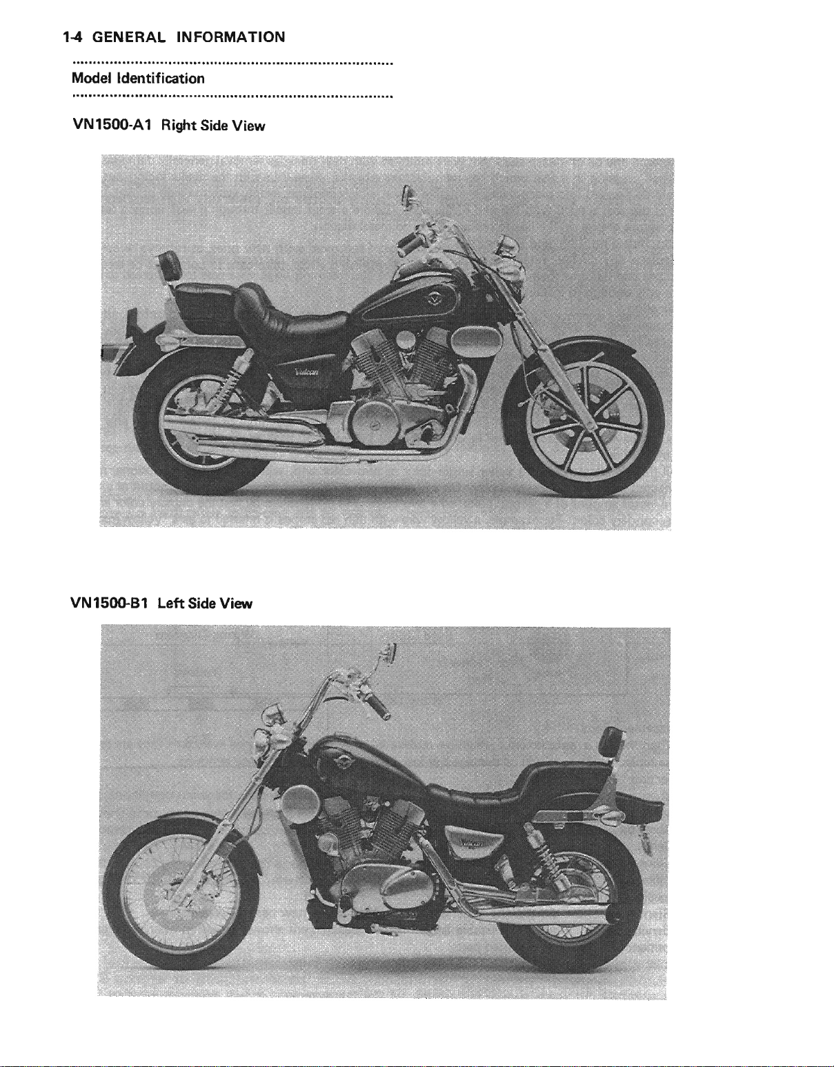
GENERAL ]NFORMATION
Model ldentification
VN1500-A1
Right
Side View
VN15qlB1
Left Side View
GENERAL
INFORMATION
16
General Specif
Items
Dimensions:
Overall length
width
Overall
height
Overall
Wheelbase
Road
clearance
height
Seat
Dry weight
weight:
Curb
Fuel tank capacity
Pertormance:
lrinimum tuming
Engine:
Type
Cooling system
Bore
and
Displacement
Compression
Maximum
Maximum
Carburetor system
Starting system
lgnition
Timing advance
lgnition timing
Spark
Cylinder
Firing order
Valve timing:
Inlet Open
Exhaust Open
Lubrication system
Engine oil: Grade
Front
Rear
radius
stroke
ratio
horsepower
torque
system
plug
numbering method
Close
Duration
Close
Duralion
Viscosity
Capacity
ications
VN1 sOGAI/AZA3/A4I
2
390
895
1 190 mm,
1 605 mm
150 mm,
720 mm,
2s2 k9,
126 kg,
154 kg,
16 L
3.0
4-stroke, SOHC,2-cylinder
Liquid-cooled
102.0 x 90.0 mm
1 470mL
9.0:1
53.0 kW
(E)
(F)
(G)
(W)
A4-(E) 44.9
A4-(G) 44.9 kW
As-(F) 43.5 kW
123.6 N-m
(A)(F)
mm,
mm
(AXE)
(AXE)
(A)(E)
(Car)2s2.5
(Cal)
(Cal)
(AXE)
mm,
(72
51.5 kW
50.0 kW
kW
s1.5
34.9 kW
(12.6
750 mm
128 kg
154.s kg,
2.7
PS) @4 500
(70
(-)@4
(70
(47.5
kW
A5I A6I A7 I
2
mm,
385
1 180 mm
lS5 mm
(E)
kg,
257 k9,
(E)
1s7 kg,
nrn
r/min
PS) @4 500
500 r/min
PS) @4 500
PS)
@3
(61
PS) @4 300
(61
PS) @4 300
(-)
@4 300 r/min
kg-m,91 ft-lb)
(F)-,(us)-
(G)
123.6 N-m
(W)
105.9 N-m
A4-(E) 112.8
A4-(G)
@3
Carburetors,
Eleclric starter
Battery and
Electronically advanced
5" BTDC @800
NGK DPRTEA-g
(AXIXU)
A11- :
Front to Rear,
'l-2
22'BrDC
66"ABDC
26A"
BBDC
66.
26. ATDC
272"
Forced lubrication
SE, SF,
10W-40, 10W-50,
sAE
L
3.5
(12.6
kg-m,91 ftlb) @3
(10.8
kg-m,78.1 tt-lb) @2
(1
1.5 k9-m,83.2
N-m
112.8 N-m
300 r/min
NGK DPRTEA-g
(U)
NGK
or SG class
(1
1.5
(rpmXDlN)
Keihin
CVK36
(transistorized)
coil
(rpm)
r/min
or ND X22EPR-Ug
DPRTEA-g or ND
1-2
(wet
kg-m,83.2 ftlb)
or ND
sump)
20W-40,
AU A9I A1OI A1 1 I NA 413
(E)
2 410
(rpm),(Us)-
r/min
(rpmXUTAC's
r/min
800 r/min
@3 000 r/min
x
2
X22EPR-U9
20W-50
(l)
mm,
2 375 mm,
(G)
256 kg
(G)
156 kg
(rpm)
norm)
(rpmXDlN)
(rpm)
(rpm)
r/min
(rpmXDlN)
r/min
(rpmXUTAC's
00o r/min
300 r/min
itlb) @3 300 r/min
)Q2EPR-U9
norm)
(rpm)
GpmXDlN)
(rpm)
(rpm)
vN1 500-81/BZB3/84/85/86
(E)
mm,
2 370
1 210 mm,
1
mm,
635
165 mn,
710 mm,
248 kg,
(E)
24e ks
kg,
121
1s4 kg,
12 L
m
3.0
=-,
(E)
(E)
(E)
160 mm
(E)
745 mm
(Cal)
(Cal)
(E)
15s kg
(w)
2 410 mm
1 195 mm
1
mm
630
248.5 kg
121.5 kg
BTDC
5"
(rpm)
1€
GENERAL
INFORMATION
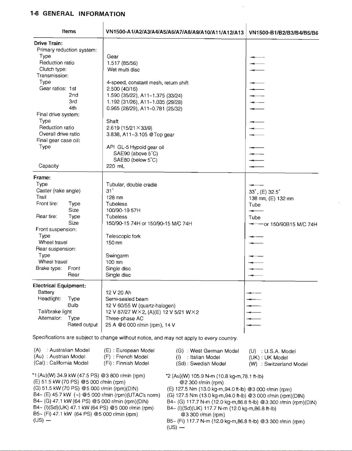
Drive
Train:
Primary
Transmission:
Final
Final
Frarne:
Type
Caster
Trail
Front
Rear
Front
Rear suspension:
Brake
reduction
Type
Reduction ratio
Clutch
lype:
Type
Gear ratios: 1st
znd
3rd
4th
drive system:
Type
Reduction
Overall
Type
Capacity
Type
Wheel travel
Type
Wheel
ratio
ratio
drive
gear
case oil:
(rake
angle)
tire: Type
Size
tire: Type
Size
suspension:
travel
type:
Front
Rear
system:
VNl500"A1IAZA3/AN
Gear
(8s/56)
1.s17
Wet multi
4-speed,
2.s00
1.s90
1.192
0.965
Shalt
2.619
3.838, 411-3.105
API
22O mL
Tubular,
31"
'128
Tubeless
100i90-19
Tubeless
15O90-15
Telescopic tork
150 mm
Swingarm
100 mm
Single disc
Single
disc
constant mesh, return
(40/16)
(35/22),
(31/26),
(28/29),
(15/21 x33/9)
GL-s Hypoid
SAE90
SAEso
mm
disc
41 1-1.375
411-1.03s
Al 1-0.781
gear
(above
(below
5"C)
double
cradle
57H
74H
o|l5cl/90-15 M/C 74H
@Top
oil
5"C)
ASIAGI A AAAgl
shift
(33t24],
(29/28)
125/32)
gear
A1U
A11tA1AA1g
vNl
500-81/B2/B3/BtyB5/B6
(E)
33'
138
Tube
Tube
=-or
32.5"
,
(E)
mm,
150/90815
132 mm
M/C 74H
Electrical Equipment:
Battery
Headlight: Type
Butb
Taiubrake
Altemator:
Specitications
Specitications
(A)
(Au)
(Cal)
"1
(Au)(W)
(E)
s1.5
(G)
s1.5 kW
(E)
84-
(G)
84-
(D(SdXUK)
84-
(Fi)
85(US) _
light
Type
Rated
are subject t(
are subject to change
: Australian
: Auslrian Model
:
Califomia Model
34.9 kW
kW
45.7 kW
47.1
47.1 kW
(70
(70
kW
Model
(47.s
PS)
@5 000 r/min
PS)
@5 @0 r/min
(-)
(64
PS)
47.1
kW
(64
12V20Ah
Semi-sealed
'12
12V
Three-phase AC
output
@5 000 r/min
PS)
25 A
(E)
(F)
(Fi)
PS) @3
@5 00o r/min
(64
800 /min
PS)
@5 000 r/min
@5 00o
beam
V 60/55 W
A7127Wxz(
@6 000 r/min
without notice,
: European
French
:
: Finnish
(rpm)
(rpmXDlN)
(rpmXUTAC's
r/min
(quartz-halogen)
Modol
Model
Model
(rpm)
(rpmXDtN)
(rpm)
(rpm)
12 V
)(E)
(rpm),
14 V
and may not
-2
(E)
norm)
(G)
8484-
85-
(us)
s/21 WX2
apply to every country.
(G)
: West
(l)
(Sd)
(AUXW)
@2 300 r/min
127.5
'i27.5
(G)
(IXSdXUK)
@3 300 r/min
(Fi)
Geman Model
: ltalian
:
117.7 N-m
117.7 N-m
Model
Swedish Model
105.9
N-m
(13.0
Nm
(13.0
Nm
117.7 N-m
-
(1o.8
kg-m,78.1
(Ipm)
kg-m,g4.O
k9.m,94.0
(12.0
(rpm)
(12.0
tr-tb)
ftlb) @3 000 r/min
kg-m,86.8
(12.0
kg-m,86.8
(U)
: U.S.A.
(UK)
:
UK Model
(W)
: Switzertand
ttlb)
@3 00o r/min
ftlb) @3 300 r/min
kg-m,86.8
ft-lb)
t-tb) @3 300 r/min
Model
Modet
(rpm)
(rpmXDtN)
(rpmxDtN)
(rpm)
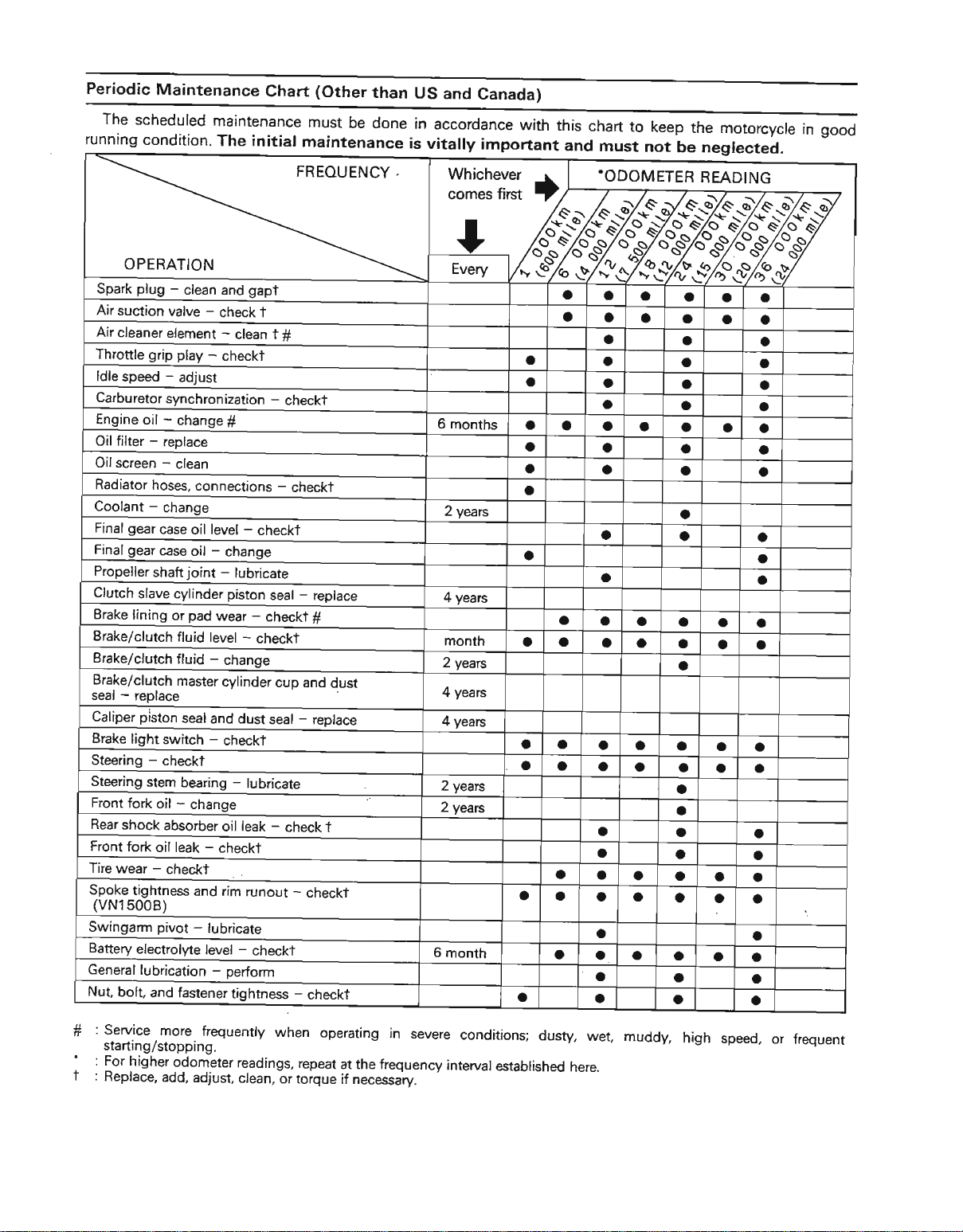
Periodic
The
running
Maintenance
scheduled
condition.
OPERATION
plug
Spark
Air
suction valve
Air
cleaner
Throttle
ldle
Carburetor
Engine
Oil lilter
Oil
Radiator
Coolant
Final
Final
Propeller
Clutch
Brake
grip
speed
oil - change
-
replace
-
screen
hoses,
-
change
gear
case
gear
case oil
shaft
slave
lining
-
synchronization
Brake/clutch
Brake/clutch
Brake/clutch
-
seal
replace
piston
Caliper
Brake light
Steering
Steering
Front
Rear
Front
Tire wear
Spoke
(vN15008)
Swingarm
Baftery
General
Nut,
switch
-
checkl
stem
fork
oil - change
shock absorber
fo*
oil leak
-
checkt
tightness
pivot
elgctrolyte
lubrication
bolt, and fastener
Chart
maintenance
The
initial
-
clean
element
play
qdiust
clean
connections
oil level
joint
cylindg
pad
or
fluid
fluid
master
seal
bearing - lubricate
and rim
-
gapt
and
-
check t
-
clean t
-
checkt
#
-
checkt
-
change
-
lubricate
piston
-
wear
levet
-
-
checkt
change
checkt
cylinder
and
dust seal - reprace
-
checkt
leak
oil
-
checkt
runout
lubricate
-
tevel
checkl
-
oerform
tightness
(Other
must
be
maintenance
FREOUENCY.
#
-
checkt
-
checkt
seal - replace
#
cup
and dust
-
check
T
-
checkt
-
checkt
than
US and
done in
is vitally
Canada)
accordance
important
6 months
yeas
2
years
4
month
yeas
2
years
4
years
4
yeats
2
years
2
6 month
with
a
a
o o
a
a
a
O
a
a
a
a
a
this
and
a
a
a
o
a
a
a
a
o
chart
must
O
o
a
a
o
o
a
a
a
a
a
a a
a
a
a a
a
a
a a
a
a
a
a
a
to keep
not
be
o
a
o
o
a
a
a
a
a
a
a
a
a
o
o
a
a
a
a
o
a
a
a
a
a
a
a
the
motorcycle
neglectei.
a
a
o
a a
o
a
a
a
a a
a
a
a
a
a
a a
good
in
o
a
o
a
o
a
o
a
a
a
a
a
a
a
a
a
a
a
a
O
a
:
Service , more.
starting/stopping.
: For
higher
:
T
heprace,
frequently
odometer
add, adJust,
when
re€dings,
ctean,
or torque if
operating in
repeat
at the frequency
necessary.
severe
interval
conditions;
established
dusty,
here.
wet, muddy,
high
speed,
or frequent
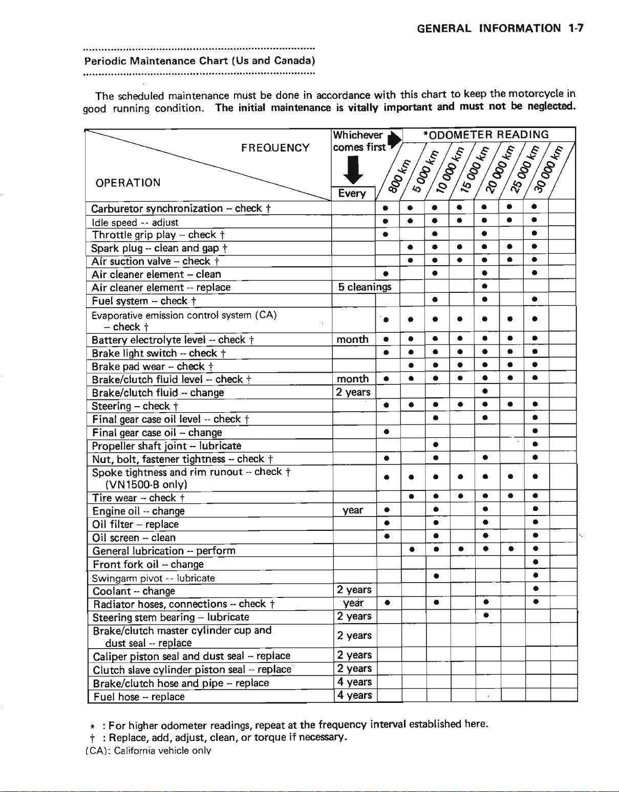
Periodic
Maintenance Chart
(Us
and Canada)
GENERAL
INFORMATION 1.7
The
good
scheduled
running condition,
maintenance
OPERATION
Garburetor
ldle soeed
Throttle
Spark
Air suction
Air cleaner
cleaner element
Air
s,ynchronization
--
adiusl
grip play
-
plug
clean and
valve - check
element
Fuel system - check
Evaporative emission
-
check
Batterv
Brake
Brake
Brake/clutch
Brake/clutch
Steerins
Final
Final
Propeller shaft
Nut, bolt.
Spoke
(VN1500-8
Iire wear - check t
Enqine oil
filter - replace
Oil
screen - clean
Oil
General
Front fork oil - chanqe
Swinqarm
Coolant
Radiator
Steering
Brake/clutch
dust seal - reolace
Caliper oiston
Clutch slave
Brake/clurch
Fuel hose - reolace
t
electrolvte
liqht
s\n,itch
wear
-
check
pad
fluid level - check
fluid - chanqe
-
check
i
qear
case oil
gear
case oil - change
ioint
fastener tightness
tightness
and
only)
-
chanqe
lubrication
--
pivot
-
change
lubricate
hoses, connections
stem bearing
master cylinder
seal
cvlinder
hose and
must be done
initial maintenance is vitally
The
in
accordance with
Whichever
FREOUENCY
comes
I
-
check
i
-
check
-
-
control system
level - check
-.
check
level - check
-
and dust
1
gap
t
J
clean
replace 5 cleaninqs
t
(CA)
t
month
f
f
I
month
2
vears
t
-
lubricate
-
check
rim runout
-
check
1
i
year a
perform
yearc
2
-
lubricate
piston
pipe
-
check
1
cup and
seal - replace
-
replace
seal
-
replace
year
years
2
years
2
yearc
2
years
2
years
4
years
4
important
first
a
o a
a
a
a
a
a
a
a
a
a
O
a
a
a
to
chart
this
and
TODOMETER
a a
a
a
a a a
a
a
a
a a a
o
a a a
a
a a
O o
o a a
a
a a
a
a a a
a
a
a
a
a a
a a
a
a
a
a a
a
a
keep the
must
motorcycle
not be neglected.
READING
a a
a
a
a a
a a a a
a a a
a a a a
a a
a a o
a
a a
a
a
a
a a
a a
a a
a a a
a
a a
a
a
a a
a a
a a
a a
a a a
a
a
in
a
o
a
a
a
a
a
o
a
a
a
a
r
: For higher odometer
: Replace, add, adjust,
t
(CA):
California vehicle only
readings, repeat at
clean, or torque
if
frequency
the
necessary.
interval eEtablished
here.
1€
GENERAL
INFORMATION
Torque
a non-permanent
Letterc
L
ss
M
o
b
st
Cooling
Engine
and
Locking
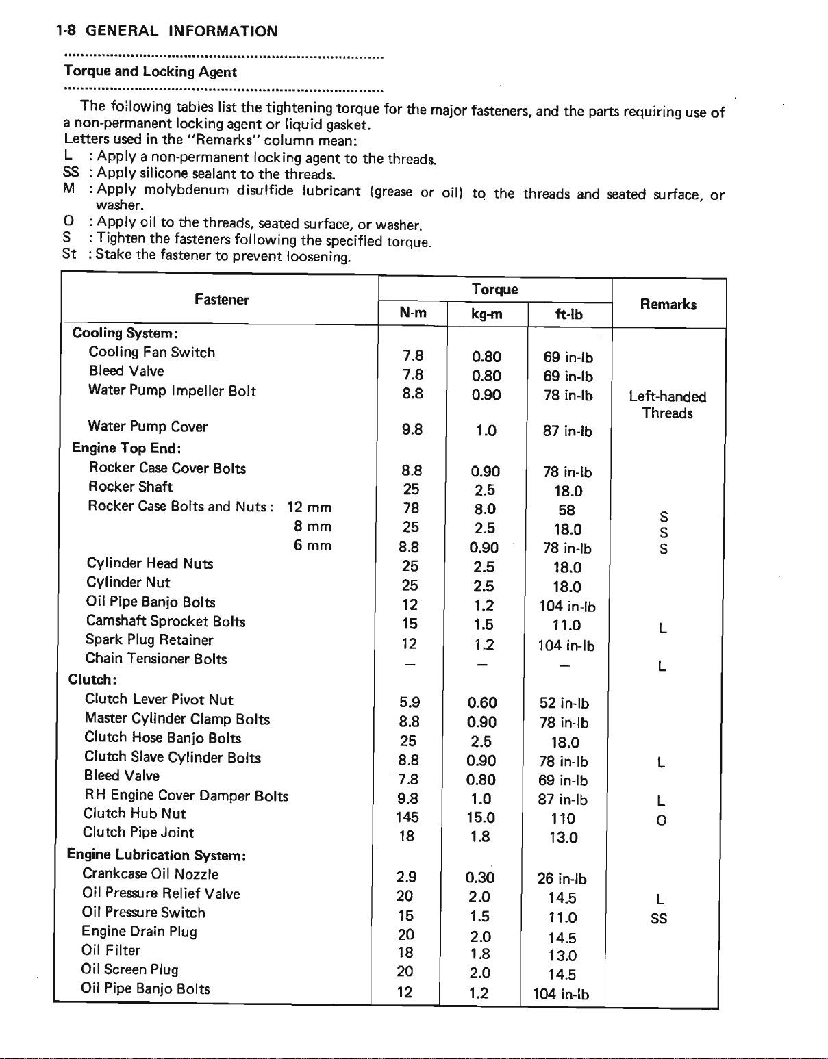
The foilowing
used in
Apply
Apply
Apply
washer.
Apply
Tighten
stake
the
a non-permanent
silicone
molybdenum
oil
to the
the fasteners
the fastener
System:
Cooling
Bleed
Fan
Valve
Water Pump
Water Pump
Top End:
Rocker
Rocker
Rocker
Cylinder
Cylinder
Oil Pipe
Camshaft
Spark Plug
Chain
Case Cover
Shaft
Case Bolts
Head
Nut
Banjo
Sprocket
Retainer
Tensioner
tables list
Switch
lmpeller
Cover
Clutch:
Clutch Lever
Master
Clutch
Clutch
Bleed
Valve
RH Engine
Clutch
Clutch
Engine
Crankcase
Oil
Oil
Engine
Oil Filter
Oil
Oil
Pioe
Lubrication
Pressre
Prescrre
Drain Plug
Screen Plug
Pipe
Pivot
Cylinder
Hose
Banio
Slave
Cylinder
Cover
Hub
Nut
Joint
Oil Nozzle
Relief
Switch
Banjo
Agent
locking
agent
"Remarks"
sealant
threads,
following
prwent
to
Fascner
Bolt
Bolts
and Nuts :
Nuts
Bolts
Bolts
Bolts
Nut
Clamp Bolts
Bolts
Bolts
Damper
System
Valve
Bolts
the tightening
or liquid
column mean:
locking
to the threads.
disrlfide
seated
agent
lubricant
zurface,
the
loosenins.
12 mm
8mm
6mm
Bolts
:
torque for
gasket.
to the
(grease
or washer.
specified
the
major
threads.
or
toroue.
N-m
7.8
7.8
8.8
9.8
8.8
25
78
25
8.8
25
25
12
15
12
5.9
8.8
25
8.8
7.8
9.8
145
18
2.9
20
15
N
18
20
12
fasteners,
oil)
tq the threads
Torque
kgrn
0.80
|
0.80
|
| 0.90
1.0
0.90
2.5
8.0
2.5
0.90
2.5
2.5
1.2
1.5
,:
0.60
0.90
2.5
0.90
0.80
1.0
15.0
1.8
0.30
2.O
1.5
2.O
1.8
2.O
1.2
and the
ft-lb
in-lb
69
69 in-lb
78 inlb
87 in-lb
78 in-lb
18.0
58
18.0
78
in{b
18.0
18.0
104
inlb
11.0
'104
in-lb
52 in-lb
78 in-lb
18.0
78 in-lb
69 inlb
87 in-lb
110
13.0
26 in-lb
14.5
11.0
14.5
13.0
14.5
l(X
in-lb
parts
requiring
and seated sr rface,
use
Remarks
Left-handed
Threads
S
S
s
L
L
o
L
SS
of
or
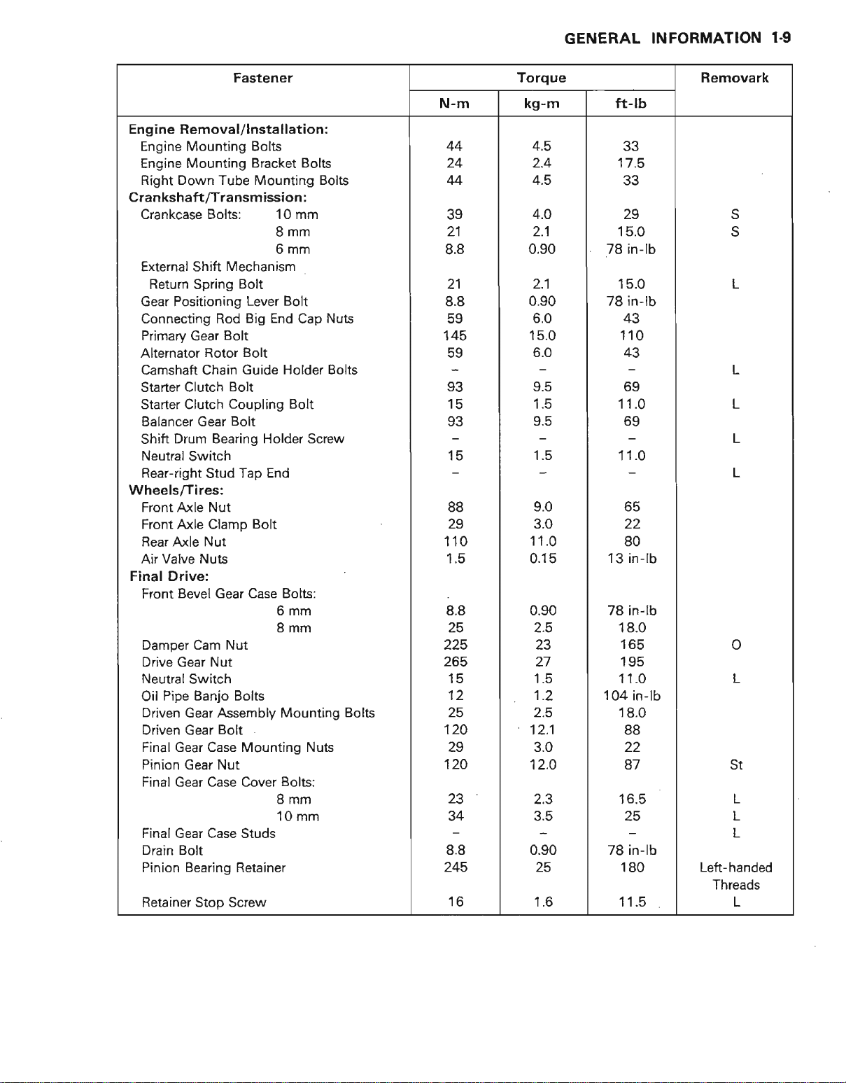
GENERAL
INFORMATION
1-9
Fastener
Engine
Crankshaft
Wheels/Tires:
Final
Removal/lnstallation:
Engine Mounting Bolts
Engine Mounting Bracket
Right Down Tube Mounting
/Transmission:
Crankcase Bolts: 10
External
Return
Gear Positioning Lever
Connecting Rod Big End Cap NUts
Primary Gear Bolt
Alternator Rotor Bolt
Camshaft Chain Guide Holder
Starter Clutch
Starter
Balancer Gear Bolt
Drum Bearing Holder
Shift
Neutral
Rear-right Stud
Front Axle Nut
Front Axle Clamp Bolt
Rear Axle
Air Valve Nuts
Drive:
Front Bevel Gear Case
Damper Cam Nut
Drive Gear Nut
Neutral Switch
Pipe Banjo Bolts
Oil
Driven Gear Assembly Mounting
Driven Gear Bolt
Final Gear Case Mounting Nuts
Pinion Gear Nut
Final Gear Case Cover Bolts:
Final Gear Case Studs
Drain
Bolt
Pinion Bearing Retainer
Retainer Stop Screw
Mechanism
Shift
Spring
Clutch Coupling
Switch
Bolt
Bolt
Tap End
Nut
Bolts
Bolts
mm
8mm
6mm
Bolt
Bolt
Screw
Bolts:
6mm
8mm
8mm
10 mm
Bolts
Bolts
N-m
44
24
44
?o
21
8.8
21
8.8
59
'|
45
93
:,5
,tt
88
29
110
1.5
8.8
25
225
265
15
12
25
120
29
120
t2
34
8.8
245
16
Torque Removark
kg-m
4.5
2.4
4.5
4.0
2.1
0.90
1.1
0.90
6.0
15.0
6.0
Y.C
ft-rb
33
'17
.5
55
29
15.0
78 in-lb
15.0
78
in-lb
+J
110
43
o:,
11.0
11 .0
L
L
L
L
9.0
?n
11.0
0.15
0.90
2.5
23
22
80
13 in-lb
78 in-lb
18.0
toc
o
27
I.C
1.2
2.5
12.1
3.0
12.O
2.3
?E
oso
25
1.6
11.0
104 in-lb
18.0
88
22
6t
1 6.5
.,8
ZS in-f
O
180
11.5
L
St
L
L
L
Left-handed
Threads
L
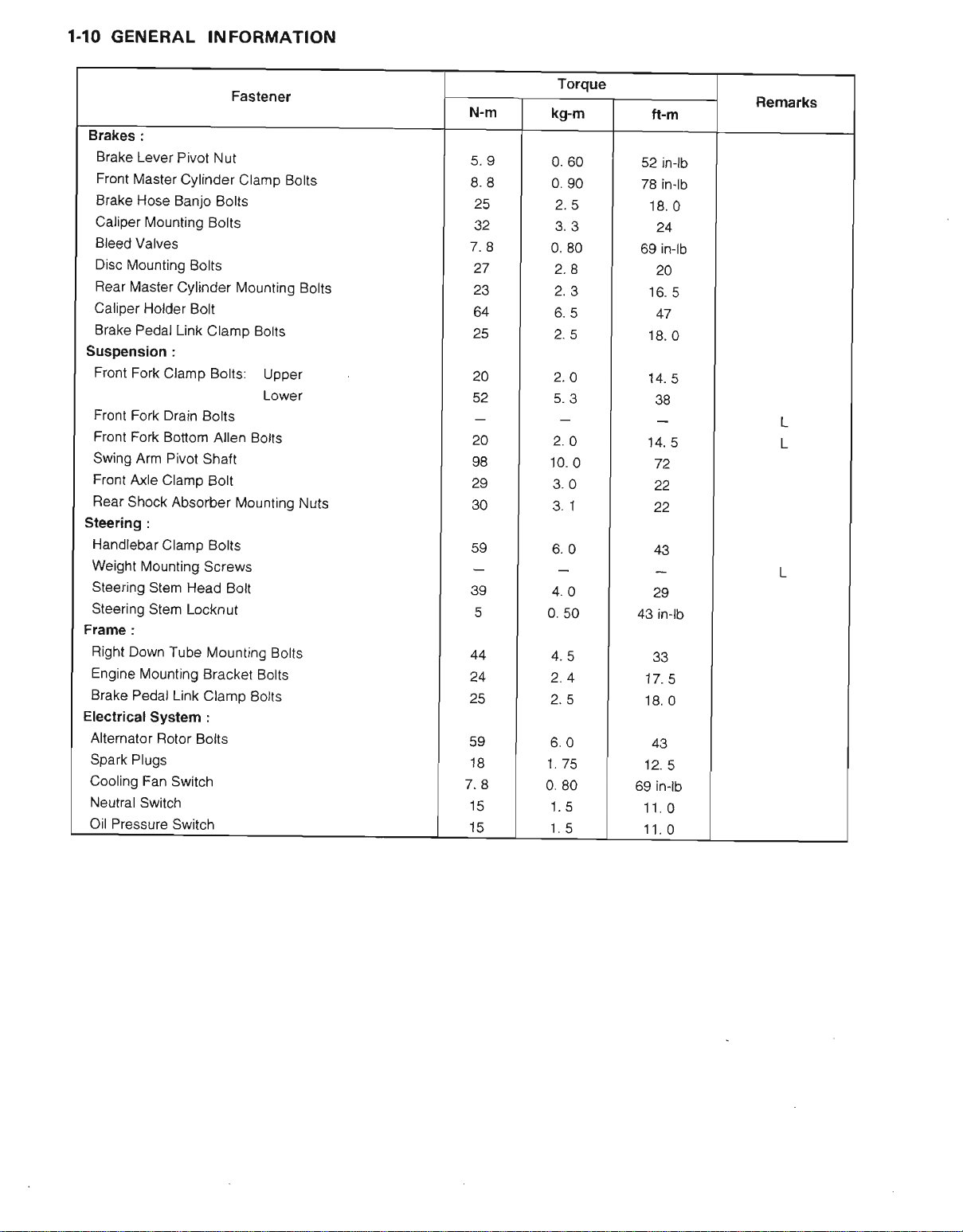
1-IO GENERAL
INFORMATION
Brakes
:
Brake
Lever Pivot Nut
Front
lvlaster
Brake
Hose Banjo
Cylinder
Caliper Mounting
Bleed
Valves
Disc
Mounting
Rear
Master
Cylinder Mounting
Caliper Holder
Brake
Pedal
Link Clamp Botts
Suspension :
Front
Fork
Clamp Bolts:
Front Fork
Front
Swing Arm
Front
Fear
Drain Bolts
Fork Bottom
Pivot
Axle
Clamp Bolt
Shock
Absorber l\ilountjng
Steering :
Handlebar
Weight
Steering
Steering
Ftame
Right Down
Engine
Brake
Electrical
Alternator
Spark
Cooling Fan
Neutral
Oil Pressure
Clamp Bolts
Mounting
Stem Head Bolt
Stem
:
Tube
Mounting
Pedal
Link
System :
Rotor Bolts
Plugs
Switch
Switch
Switch
Fastener
Clamp Bolts
Bolts
Bolts
Bolts
Bolt
Allen
Botts
Shaft
Screws
Locknut
Mounting Bolts
Bracket Bolts
Clamp Botts
Upper
LOWer
Bolts
Nuts
N-m
8.8
25
32
7.8
27
23
64
25
20
52
20
98
29
30
59
44
24
z5
59
18
7.8
15
15
Torque
kg-m
0.
60
0. 90
2.5
0. 80
2.8
2.3
6.5
2.5
2.O
5.3
2.O
10.
0
3.0
3. 1
6.0
4.O
0. 50
4.5
2.4
2.5
6.0
1.75
0. 80
'1.
5
t. c
ft-m
52 inlb
78 inlb
18.
69 in-lb
20
to. c
47
18.
0
'14.
5
38
14. 5
72
2.
22
zl3
29
43 inlb
33
17.
5
18.
0
43
't2.
5
69 inlb
11.0
11.0
Remarks
0
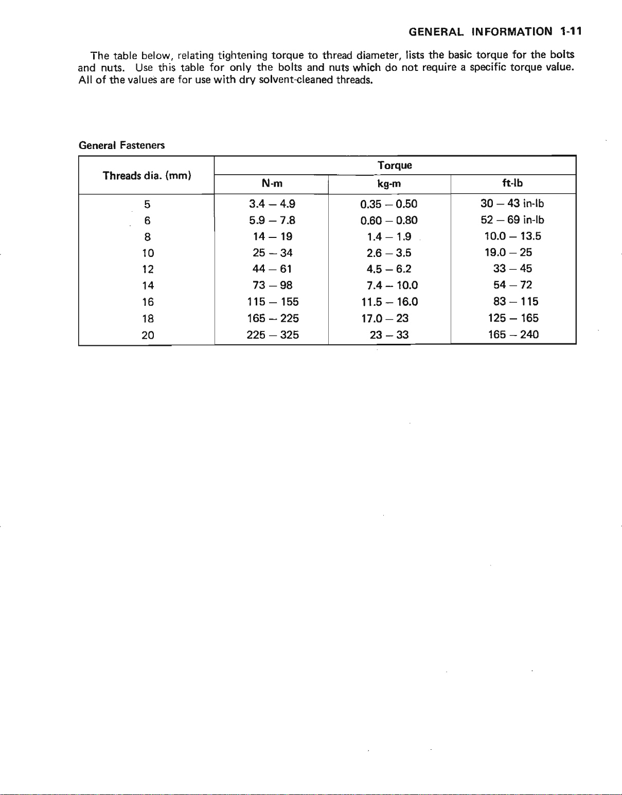
GENERAL INFORMATION
1.11
table below,
The
nuts. Use this table
and
All of the
General Fastenen
values are
Threads
dia.
c
6
8
10
12
14
16
18
20
relating tightening torque to thread diameter,
for only
for use with dry solvent+leaned
bolts and nuts
the
which do not
threads,
Torque
(mml
N-m
-
3.4
4.9
5.9 - 7.8
14-19
-34
25
-61
44
73-98
115- 155
-225
165
225-325
kgm
0.35
0.60
1.4
2.6
4.5
7.4
11.5
17.O
23 - 3:t
lists *re basic torque
require a
-
0.50
-
0.80
-
1.9
-
3.5
-6.2
-
10.O
-
16.0
-23
specific
ft-lb
-
zt3
30
-
69 in-lb
52
10.0 - 13.5
-
19.0
33-45
-72
54
83 - 115
125 - 165
-
165
for
the
torque
in-lb
25
2'10
bolts
value.
1-12
GENERAL INFORMATION
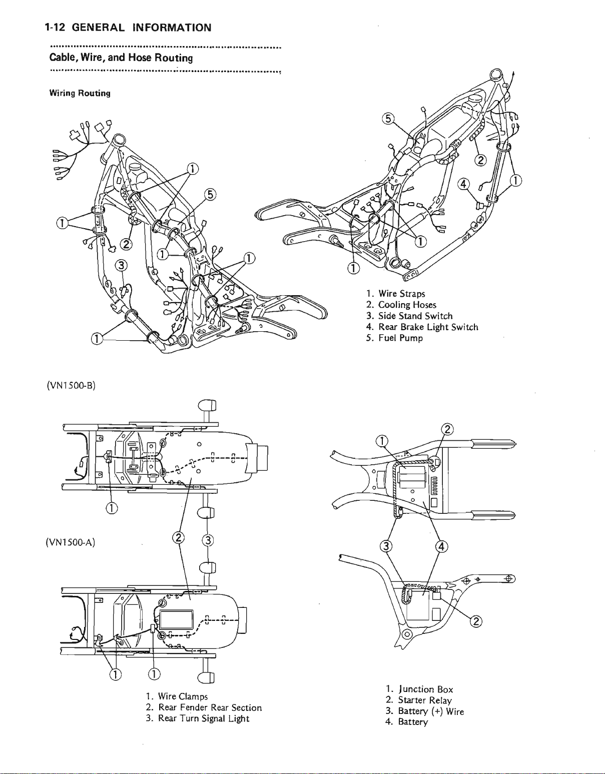
Cable,
Widng Routing
Wire,
and Hose
Routing
................;,,.......
1 . Wire
2.
3.
4. Rear Brake
5. Fuel Pump
Straps
Cooling Hoses
Side Stand Switch
Light Switch
(vN1500-B)
1. Wire
2.
3. Rear Turn
Clamps
Rear Fender Rear
Signal Light
Section
1. J unction
2. Sarter
3. Battery (+)
4.
Battery
Box
Relay
Wire
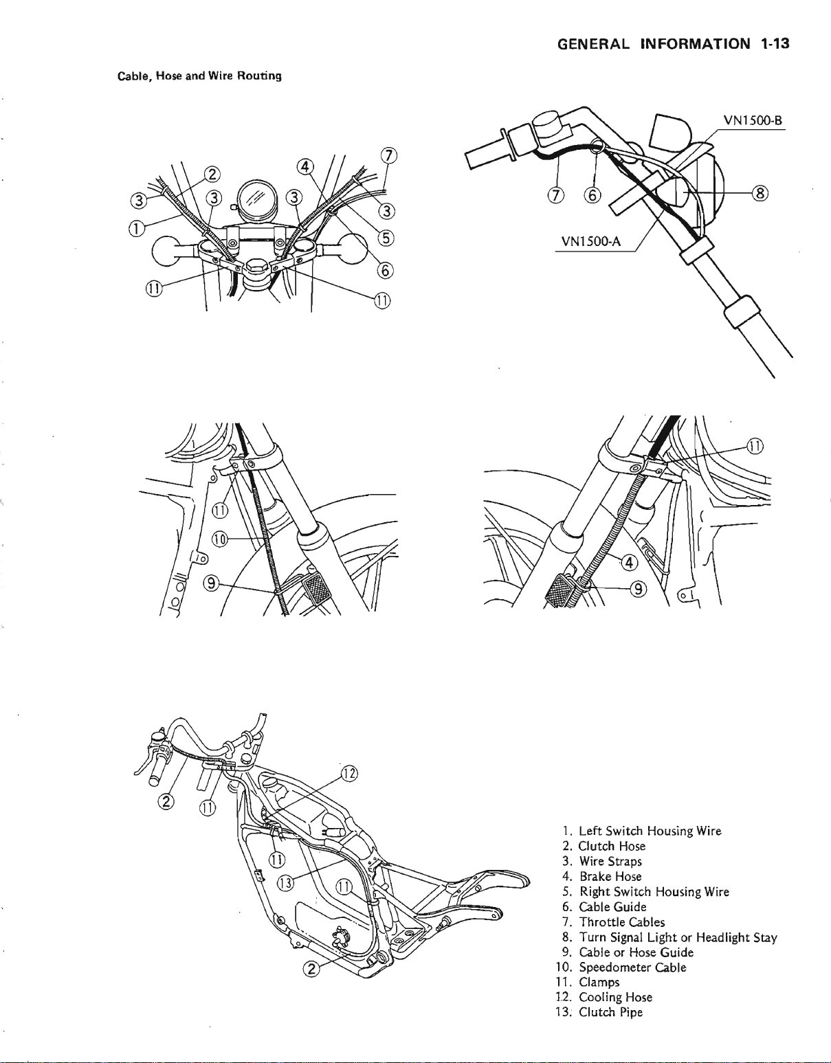
Hose and Wire Rouling
Cable,
GENERAL
INFORMATION 1.13
l. Left
2.
3. Wire
4. Bnke
5. Right
6. Cable Guide
7.
8.
9. Cable or Hose
.l0.
11.
12.
13: Clutch Pipe
Switch
Clutch Hose
Throttle
Turn Signal Light or Headlight
Speedometer Cable
Clamps
Cooling Hose
Straps
Hose
Switch
Cables
Housing Wire
Housing Wire
Guide
Stay
1-14
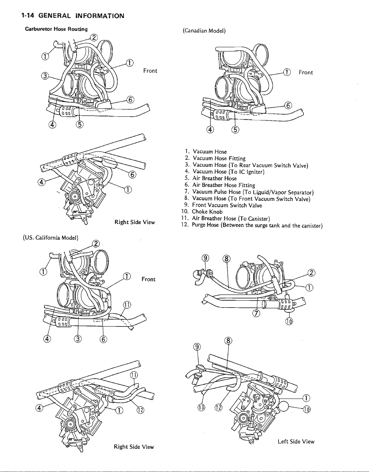
GENERAL
INFORMATION
Carburetor Hose
Routing
(Canadian
l.
Vacuum
2.
Vacuum
3.
Vacuum
4.
Vacuum
5.
Air
Breattrer
6. Air
Breather
7.
Vacuum
8.
Vacuum
9. Front
10.
Choke
l l.
Air
'12.
Breatfter
Purge
Model)
Hose
Hose
Hose
Hose
Hose
Hose Fitting
Pulse
Hose
Vacuum
Knob
Hose
(Between
Hose
Fitting
(To
Rear Vacuum
(To
IC
lgniter)
(To
Hose
(To
Switch Valve
Liguid/Vapor
Front
Vacuum
(To
Canister)
the
surge tank and
Switch Valve)
Separator)
Switch
Valve)
the canister)
(US.
California Model)
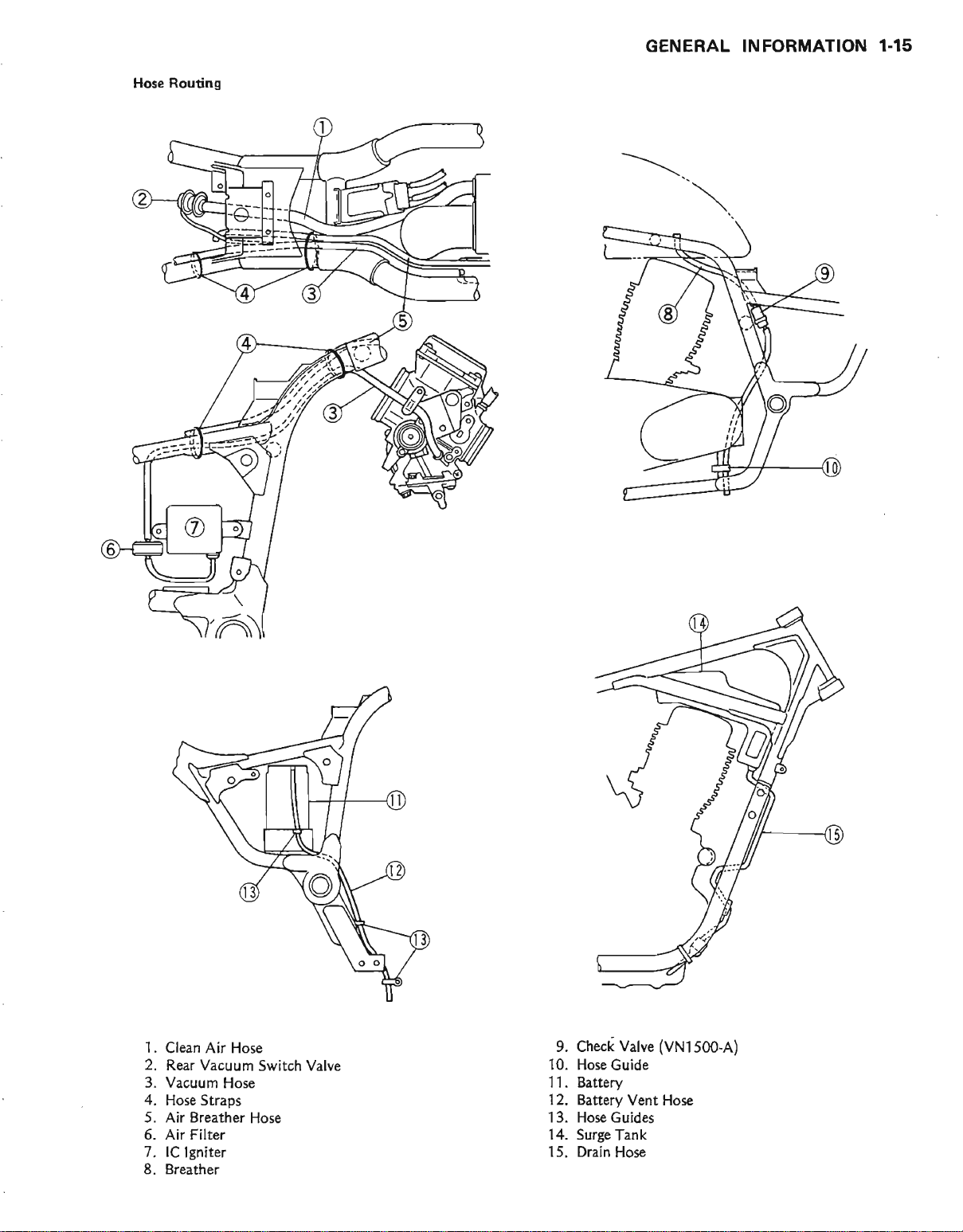
Hose Routing
GENERAL
INFORMATION 1.15
1
. Clean Air Hose
2. Rear
3. Vacuum Hose
4. Hose
5. Air
6.
7.
8.
Vacuum
Straps
Breather Hose
Filter
Air
lC lgniter
Breatier
Switch Valve
9. Check Valve
10. Hose
11. Battery
12. Battery Vent
13,
14.
15, Drain
Guide
Hose Guides
Surge Tank
Hose
(VNl500.A)
Hos€
1.16
GENERAL INFORMATION
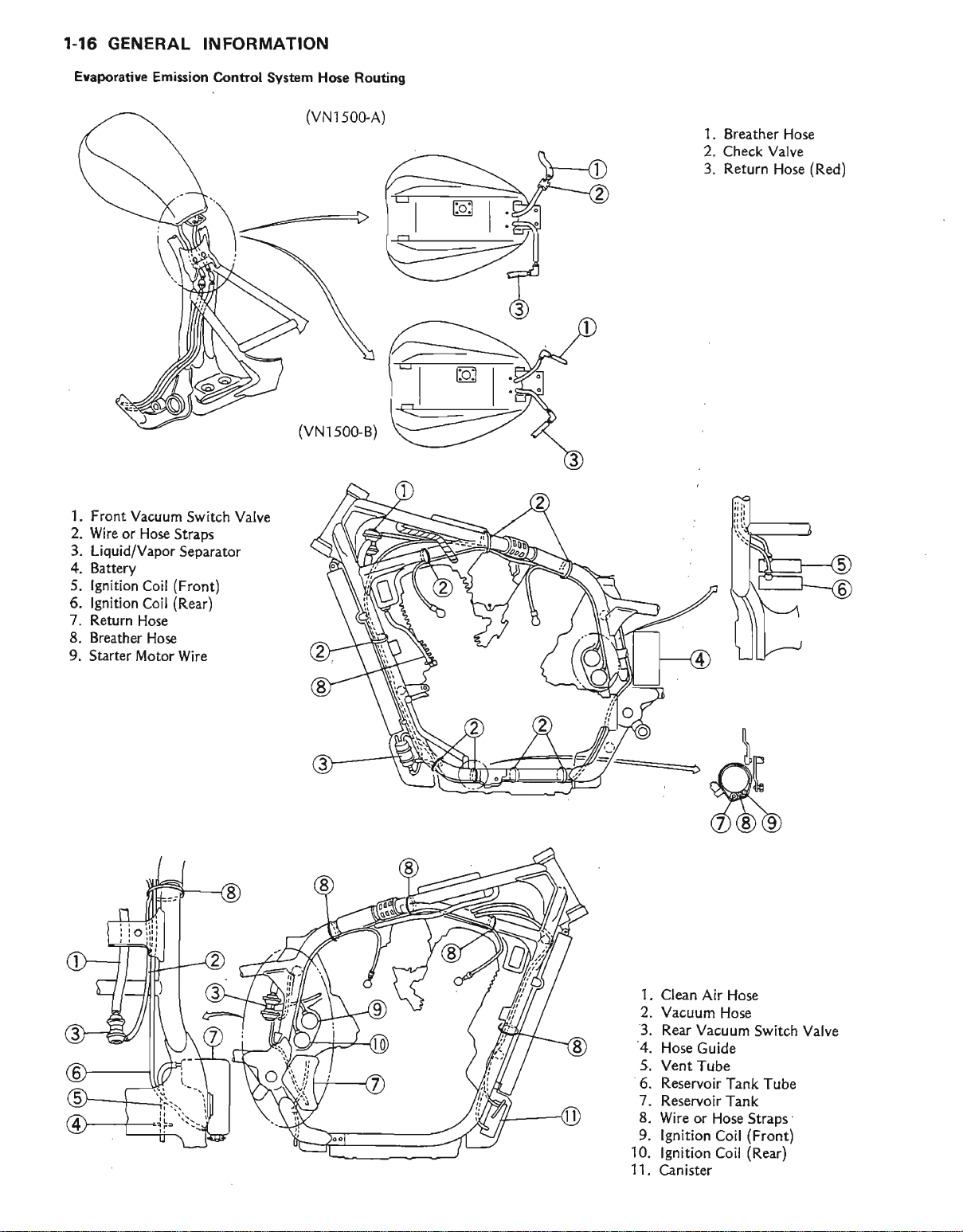
Evaporative Emission
1.
Front Vacuum
2. Wire
3. Liquid/Vapor
4. Batttry
5.
6. lgnition
7. Return
8. Breather
9.
or Hose
lgnition
Hose
Starter Motor
Coil
Coil
Hose
Straps
(Front)
(Rear)
Switch Valve
Separator
Wire
Control System Hose Routing
(vNlsoGA)
(vN1s00-B)
'..__
-E
i------E--i-
I
*l:
1.
Breather Hose
Check Valve
2.
Return Hose
3.
(Red)
1.
Clean Air
2, Vacuum
'3.
Rear Vacuum
'4.
Hose
Guide
5. Vent
6. Reservoir
7. Reservoir
8. Wire
9. lgnition
10.
11.
Tube
or Hose
lgnition
Canister
Hose
Hose
Switch Valve
Tank Tube
Tank
Straps
(Front)
Coil
(Rear)
Coil
GENERAL INFORMATION
T-17
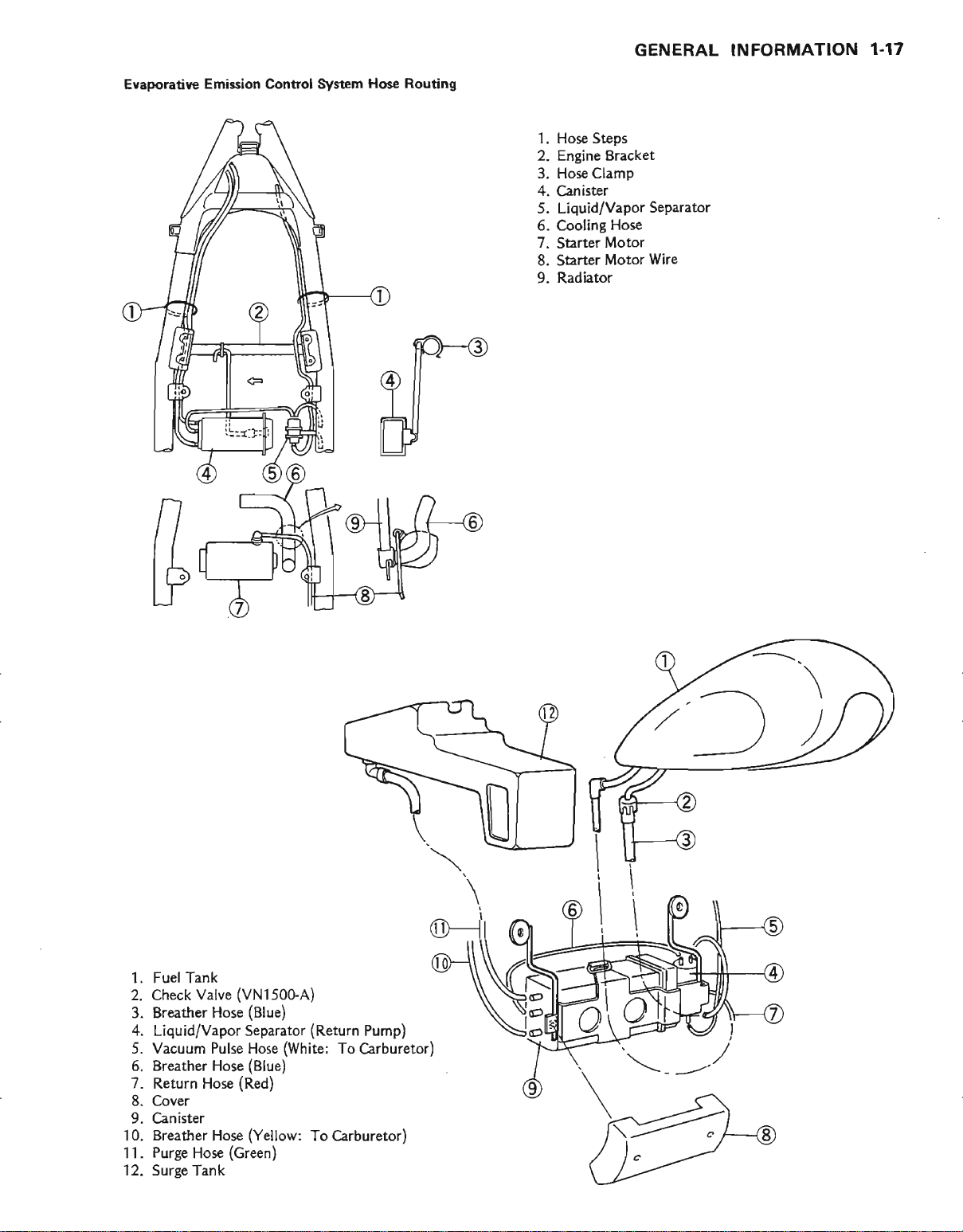
Eyaporatiye Emi$ion
control
System
Hose Routing
l. Hose St€ps
2. Engine Bracket
3. Hose Clamp
4. Canister
Hose
Motor
Motor
Separator
Wire
5.
Liquid/Vapor
5. Cooling
7. Starter
8. Starter
9. Radiator
1. Fuel Tank
2.
Check
3. Breather Hose
4.
Liquid/Vapor Separator
5. Vacuum Pulse Hose
6. Breather Hose
7. Return Hose
8. Cover
9. Canister
10. Breather Hose
11. Purge Hose
12. Surge Tank
Valve
(Green)
(VN150GA)
(Blue)
(Blue)
(Red)
(Yellow:
(Return
(White:
To Carburetor)
To Carburetor)
,/.-\
,)
Pump)
I.18 GENERAL
]NFORMATION
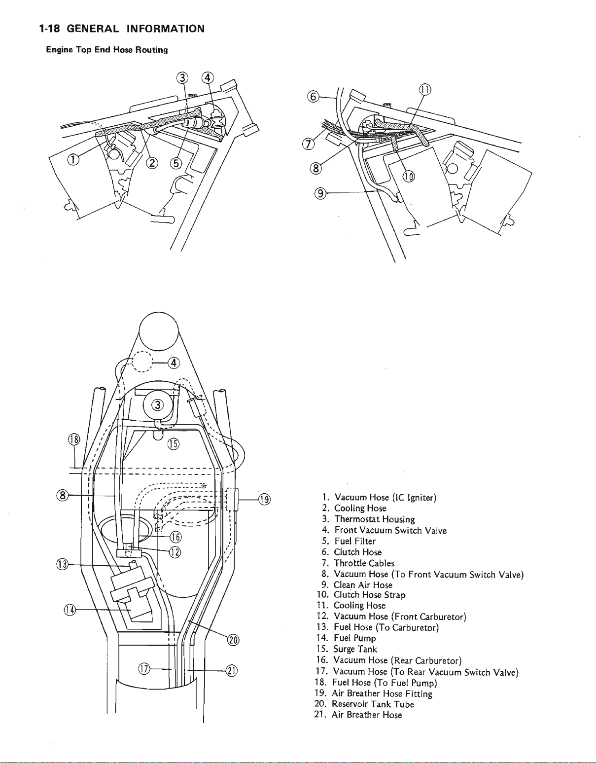
Engine
Top End Ho.e Routing
'!i!
,-'.------'-
1. Vacuum
2.
Cooling Hose
3. Thermostat
4.
Front Vacuum
5. Fuel Filter
5. Clut h Hose
7. Throitle
8.
Vacuum Hose
9.
Clean Air Hose
10.
Clutch Hose
11.
Cooling Hose
12. Vacuum
13.
Fuel Hose
14. Fuel
15.
Pump
Surge Tank
16. Vacuum
17. Vacuum
18.
Fuel Hose
19.
Air Breather
20.
Res€rvoir
21.
Air Breather
Hose
Housing
Cables
(To
Strap
(Front
Hose
(To
(Rear
Hose
(To
Hose
(To
Fuel Pump)
Hose
Tank
Hose
(lC
lgniter)
Switch Valve
Front Vacuum
Carburetor)
Carburetor)
Carburetor)
Rear Vacuum
Fitting
Tube
Swirch Valve)
Switch Valve)
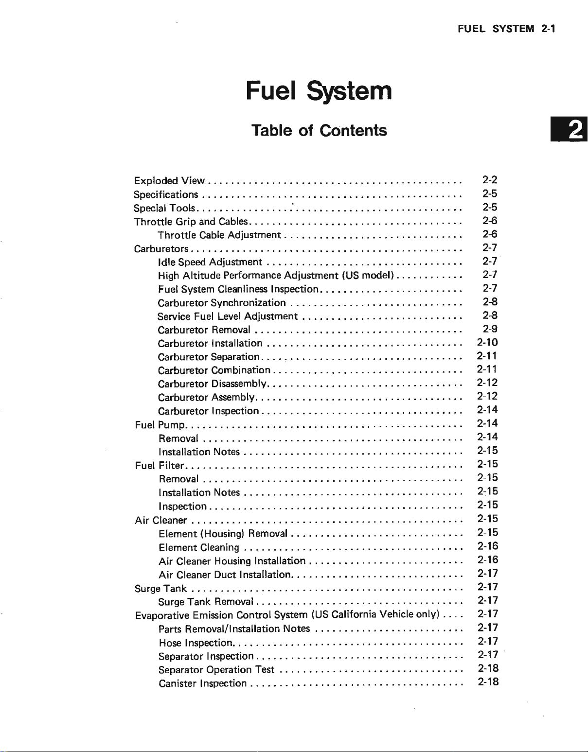
FUEL SYSTEM2-1
ExplodedView...
Specifications
SpecialTools.
Throttle Grip
Throttle Cable
Carburetorc,
ldle Speed
High Altitude Performance
Fuel
Carburetor
Service
Carburetor
Carburetor
Carburetor
Carburetor
Carburetor
Garburetor
Carbu
Pump.
Fuel
Removal
lnstallation
Fuel Filter.
Removal
lnstallation
Inspection
Air Cleaner
Element
ElementCleanins
Air Cleaner
Air Cleaner
Tank
Surge
Surge
Evaporative
and Cables.
Adjustment
Adiustment
System
retor
Tank Removal
Cleanliness
Synchronization
Fuel Level
Removal
I nstallation
Separation. .
Combination
Disasembly.
Assembly.
I nspection,
Notes . .
Notes . ,
(Housing)
Housing
lnstallation
Duct
Emission Control
Pans Removal/lnstallation
Hose Inspection.
Separator
Inspection
Separator Operation
Canister
Inspection
Fuel
Table
......,.'.
.
I nspection.
Adjustment . . . . .
,
. . . .
Removal
.. ....
Installation...
System
System
of
Contents
Adjustment
(US
Notes
. .
.
Test
(US
model) .
.
. .
California
Vehicle only)
' . . '
2-2
2-5
2-5
2-6
2$
2-7
2-7
2-7
2-7
24
24
2-9
2-10
211
2-11
2-12
2-12
2-14
2-14
2-14
2-15
2-15
2-15
2-15
2-15
2-15
2-15
2-16
2-16
2-17
2-17
2-17
2-17
2-17
2-17
2-17
2-18
2-18
2.2
FUEL
SYSTEM
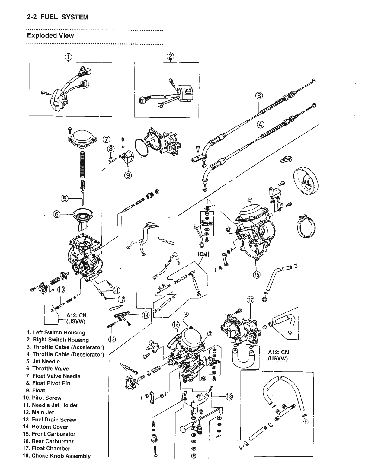
Exploded
View
?."---x
V
6
g
g
n
!
@-_-1
@-+
va
(D
f---r
t^l
I A- |
IfrPtri
i\
€-
p
R
l,lf
re
1. Left
Switch Housing
2. Right
3. Throttle
4. Throtlle
5. Jet Needle
6.
7. Float
8.
9. Float
t0.
11.
12.
13. Fuel Drain
14. Botlom
15.
16.
17. Float
18.
Switch Housing
Cable
Cable
Throttle
Float
Pilot
Needle
Main Jet
Front
Rear Carburetor
Choke Knob
Valve
Valve Needle
Pivot Pin
Screw
Jet Holdei
Cover
Carburetor
Chambel
u)
A12: CN
(us)(vy)
(Accelerator)
(Decelerator)
Screw
Assembty
€
\s6
sBe
,u&^,
PEB
a
a
./'1
"al
""\.€
A12:
CN
(US)(w)
g
t
FUEL
SYSTEM
2.3
A12: CN
(usxw)
a
rlr
o-l
I iEi
frl
tui
es
i9t
u
A12:
CN
(us)w)
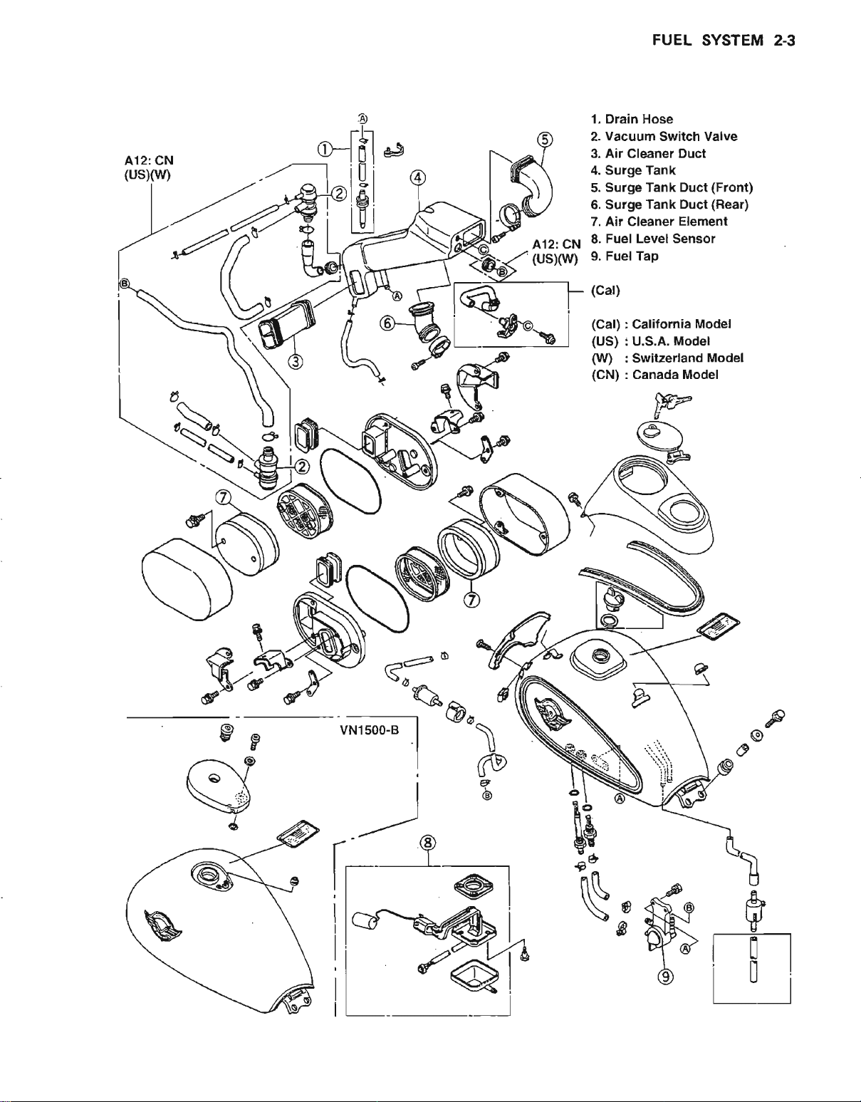
1. Drain Hose
2. Vacuum Switch Valve
Air
3.
Cleaner
4. Surge Tank
5. Surge
6. Surge Tank
7. Air Cleaner Element
Fuel
8,
Fuel Tap
9.
(cal)
(cal)
Calitornia Model
(us)
U.S.A.
(W)
Sruitzerland Model
(cN)
Canada
Duct
Tank Duct
Duct
Level Sensor
Model
Model
(Front)
(Rear)
u-)
<-'
------46,
vNlsoGB
I
a
I
$
A
e
\il
rT-t
i0i
tl
 Loading...