

Kawasaki Ninja ZX-10R ABS 2013 Owner's manual
Quick Reference Guide
This Quick Reference Guide will
assist you in finding the information
you’re looking for.
A Table of Contents is included after
the Foreword.
GENERAL INFORMATION j
HOW TO RIDE THE MOTORCYCLE j
SAFE OPERATION j
MAINTENANCE AND ADJUSTMENT j
STORAGE j
TROUBLESHOOTING GUIDE j
Whenever you see the symbols
shown below, heed their instructions!
Always follow safe operating and maintenance practices.
NOTICE
NOTICE is used to address practices not related to personal injury.
DANGER
DANGER indicates a hazardous
situation which, if not avoided,
will result in death or serious in-
jury.
WARNING
WARNING indicates a hazardous
situation which, if not avoided,
could result in death or serious
injury.
NOTE
NOTE indicates information that may
○
help or guide you in the operation or
service of the vehicle.
WARNING
Engine exhaust, some of its
constituents, and certain vehicle components contain or emit
chemicals known to the State of
California to cause cancer and
birth defects or other reproductive harm.
NOTICE
THIS PRODUCT HAS BEEN
MANUFACTURED FOR USE IN A
REASONABLE AND PRUDENT
MANNER BY A QUALIFIED OPERATOR AND AS A VEHICLE
ONLY.

FOREWORD
Congratulations on your purchase of a new Kawasaki motorcycle. Your new motorcycle is the product of Kawasaki’s advanced engineering, exhaustive testing,
and continuous striving for superior reliability, safety and performance.
Please read this Owner ’s Manual carefully before riding so that you will be
thoroughly familiar with the proper operation of your motorcycle’s controls, its features, c apabilities, and limita tio ns. This manual offers many safe riding tips, but its
purpose is not to provide instruction in all the techniques and skills required to ride
a motorcycle safely. Kawasaki strongly recommends that all operators of this vehicle enroll in a motorcycle rider training p ro gram to attain awareness of the mental
and physical requirements necessary for safe motorcycle operation.
To ensure a long, trouble-free life for your motorcycle, give it the proper care and
maintenance described in this manual. For those who would like more detailed information on their Kawasaki Motorcycle, a Service Manual is available for purchase
from any authorized Kawasaki motorcycle dealer. The Service Manual contains detailed disassembly and maintenance information. Those who plan to do their own
work should, of course, be competent mechanics and possess the special tools
described in the Service Manual.
Keep this Owner’s Manual aboard your motorcycle at all times so that you can
refer to it whenever you need information.

This manual should be considered a permanent part of the motorcycle and should
remain with th e motorcycle whe n it is sold.
All rights reserved. No part of this publication may be reproduced without our
prior written permission.
This publication includes the latest information available at the time of printing.
However, there may be minor differences between the actual product and illustrations and text in this manual.
All products are subject to change without prior notice or obligation.
KAWASAKI HEAVY INDUSTRIES, LTD.
Motorcycle & Engine Company
© 2013 Kawasaki Heavy Industries, Ltd. Apr. 12, 2013. (1)

TABLE OF CO NTE NTS
SPECIFICATIONS............................... 9
SERIAL NUMBER L OCATIONS......... 13
LOCATION OF PARTS....................... 14
LOADING AND ACCESSORIES
INFORMATION ................................ 17
GENERAL INFORMATION................. 20
Meter Instruments ............................ 20
Tachometer................................... 22
Instrument Display Brightness
Control ...................................... 26
Multifunction Meter ....................... 28
Warning/Indicator Lights ............... 48
Keys ................................................. 58
Ignition Switch/Steering Lock ........... 60
Left Handlebar Switches .................. 61
Dimmer Switch ............................. 62
Turn Signal Switch ........................ 62
Horn Button .................................. 62
LAP/Passing Button...................... 62
Power/S-KTRC Button.................. 62
Right Handlebar Switches ................ 63
Engine Stop Switch ...................... 63
Starter Button ............................... 63
START/STOP Switch (for Stop
Watch)....................................... 64
Brake Lever Adjuster........................ 64
Fuel Tank Cap .................................. 65
Fuel Tank ......................................... 66
Fuel Requirement ......................... 68
Side Stand ....................................... 71
Seats................................................ 72
Tool Kit ............................................. 75
Air Cleaner Intake ............................ 75
Front Footpeg Position ..................... 76
BREAK-IN ........................................... 77
HOW TO RIDE THE MOTORCYCLE .79
Starting the Engine .......................... 79
Jump Starting ................................... 82
Moving Off........................................ 85
Shifting Gears .................................. 86

Braking............................................. 88
Kawasaki Intelligent anti-lock
Brake System (KIBS, For models
equipped with KIBS) ..................... 89
Stopping the Engine ......................... 92
Stopping the Motorcycle in an
Emergency ................................... 92
Parking............................................. 93
Catalytic Converter........................... 95
Sport-Kawasaki TRaction Control
(S-KTRC)...................................... 96
Power mode ..................................... 100
SAFE OPERATION............................. 103
Safe Riding Technique ..................... 103
Daily Checks .................................... 106
Additional Considerations for High
Speed Operation .......................... 109
MAINTENANCE AND ADJUSTMENT 111
Periodic Maintenance Chart ............. 115
Engine Oil ........................................ 128
Cooling System ................................ 133
Spark Plugs...................................... 140
Evaporative Emission Control
System (California model onl y) ..... 141
Valve Clearance ............................... 142
Kawasaki Clean Air System ............. 143
Exhaust Device ................................ 144
Air Cleaner ....................................... 145
Throttle Control System ................... 150
Engine Vacuum Synchronization ..... 153
Idle Speed ........................................ 153
Clutch............................................... 154
Drive Chain ...................................... 156
Brakes.............................................. 165
Brake Light Switches........................ 169
Electronic Steering Damper ............. 171
Front Fork......................................... 172
Rear Shock Absorber ....................... 178
Wheels ............................................. 185
Battery.............................................. 190
Headlight Beam................................ 196
Fuses ............................................... 199
General Lubrication.......................... 202
Cleaning Your Motorcycle ................ 203
Bolt and Nut Tightening.................... 210

STORAGE........................................... 213
TROUBLESHOOTING GUIDE............ 216
YOUR WARRANTY/OWNER
SATISFACTION ........................... 217
REPORTING SAFETY DEFECTS ...... 223
ENVIRONMENTAL PROTECTION..... 224
MAINTENANCE RECORD ................. 225
LOCATION OF LABELS..................... 229

SPECIFICATIONS
PERFORMANCE
Minimum Turning Radius
DIMENSIONS
Overall Length 2 075 mm (81.7 in.)
Overall Width 715 mm (28.1 in.)
Overall Hei ght 1 115 mm (43.9 in .)
Wheelbase
Road Clearance 135 mm (5.3 in.)
Curb Mass (ZX1000J) 198 kg (437 lb)
(ZX1000K) 201 kg (443 lb)
E
ENGIN
Type
Displacement
×Stroke
Bore
ression Ratio 13.0:1
Comp
3.4 m (134 in.)
1 425 mm (56.1 in.)
, 4-cylinder, 4-stroke, liquid-cooled
DOHC
m³ (60.9 cu in.)
998 c
× 55.0 mm (3.0 × 2.2 in.)
76.0
SPECIFICATIONS 9

10 SPECIFICATIONS
Starting System Electric starter
Cylinder Numberi ng
Method
Firing Order
Fuel System FI (Fuel Injection)
Ignition System Battery and coil (transistorized ignition)
Ignition Timing
(Electronically advanced)
Spark Plugs NGK CR9EIA-9
Lubrication System Forced lubrication (wet sump)
Engine Oil:
Type
Viscosity
Capacity 3.7 L (3.9 US qt)
Coolant Capacity 2.6 L (2.7 US qt)
TRANSMISSION
Transmission Type
Left to right, 1-2-3-4
1-2-4-3
10° BTDC @1 1 00 r/min (rpm) ∼ 42.5° BTDC
@10 500 r/min (rpm)
API SG, SH, SJ, SL or SM with JASO MA, MA1
or MA2
SAE 10W-40
6-speed, constant mesh, return shift

Clutch Type Wet, multi disc
Driving System Chain drive
Primary Reduction Ratio 1.681 (79/47)
Final Reducti on Ratio 2.294 (39/17)
Overall Drive Ratio 5.197 @Top gear
Gear Ratio:
1st 2.600 (39/15)
2nd 2.053 (39/19)
3rd 1.737 (33/19)
4th 1.571 (33/21)
5th 1.444 (26/18)
6th 1.348 (31/23)
FRAME
Castor 25°
Trail 107 mm (4.2 in.)
SPECIFICATIONS 11

12 SPECIFICATIONS
Tire Size:
Front 120/70ZR17 M/C (58W)
Rear 190/55ZR17 M/C (75W)
Rim Size:
Front J17M/C × MT3.50
Rear J17M/C × MT6.00
Fuel Tank Capacity 17 L (4.5 US gal)
ELECTRICAL EQUIPMENT
Battery (ZX1000J) 12 V 6 Ah
(ZX1000K) 12 V 8.6 Ah
Headlight:
High beam 12 V 55 W + 55 W
Low beam 12 V 55 W
Tail/Brake Light LED
Even if one of LED (Light Emitting Diode) tail/brake lights does not go on, consult
with an authorized Kawasaki dealer.
Specifications are subject to change without notice.
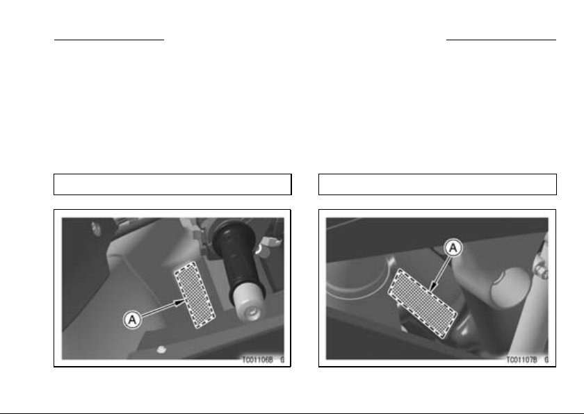
SERIAL NUMBER LOCATIONS 13
SERIAL NUMBER LOCATIONS
The engine and frame serial numbers are used to register the motorcycle. They
are the only means of identifying your particular machine from others of the same
model type. These serial numbers may be needed by your dealer when ordering
parts. In the event of theft, the investigating authorities will require both numbers
as well as the model type and any peculiar features of your machine that can help
them id entify it.
Frame No.
A. Frame Number
Engine N o.
A. Engine Number
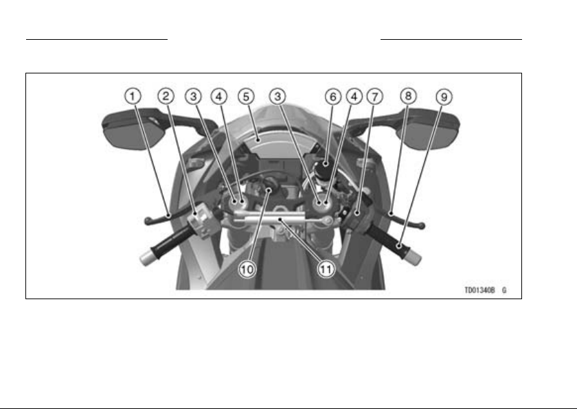
14 LOCATION OF PARTS
LOCATION OF PARTS
1. Clutch Lever
2. Left Handlebar S witches
3. Rebound Damping Force Adjuster
(Front Fork )
4. Compression damping force adjuster
(Front Fork )
5. Meter Instruments
6. B ra ke Fluid Reservoir (Front)
7. R ight Handlebar Switches
8. Fr on t Brake Lever
9. T hro ttle Grip
10. Ig nit ion Switch/Steering Lock
11. Electronic Steering Damper
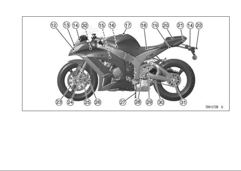
LOCATION OF PARTS 15
12. Headlight
13. Air Cleaner Intake
14. Turn Signal Lights
15. Spark Plugs
16. Air Cleaner
17. Fuel Tank
18. Rider’s Seat
19. Seat Lock
20. Passeng er ’s Seat
21. Tail/Brake Light
22. Licen se Plate Light
23. B rake Disc
24. Spring Preload
Adjuster
25. F ron t Fork
26. B rake Caliper
27. Side Stand
28. Shift Pedal
29. Compression
damping force
adjusters
30. Drive Chain
31. Chain Adjuster
32. Fuse Box
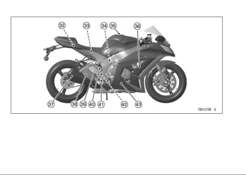
16 LOCATION OF PARTS
32. Fuse Boxes
33. B attery
34. Rebound damping force adjus ter
35. Fuel Tank Cap
36. Coolant Reserve Tank
37. Muffler
38. Swin garm
39. R ear Shock Absorber
40. B rake Fluid Reservoir (Rear)
41. R ear Brake Pedal
42. R ear Brake Light Swi tch
43. Oil Level Inspection Window
LOADING AND ACCESSORIES INFORMATION 17
LOADING AND ACCESSORIES INFORMATION
WARNING
Incorrect loading, improper installation or use of accessories,
or modification of your motorcycle may result in an unsafe riding
condition. Before you ride the
motorcycle, make sure it is not
overloaded and that you have
followed these instructions.
With the exception of genuine
Kawasaki Parts and Accessories,
Kawasaki has no control over the
design or application of accessories.
In some cases, improper installation
or use of accessories, or motorcycle
modification, will void the motorcycle
warranty, can negatively affect performance, and can even be illegal.
In selecting and using accessories,
and in loading the motorcycle, you are
personally responsible for your own
safety and the safety of other persons
involved.
NOTE
Kawasaki Parts and Accessories
○
have been specially designed for
use on Kawasaki motorcycles. We
strongly recommend that all parts
and accessories you add to your
motorcycle be genuine Kawasaki
components.
Because a motorcycle is s en sitive to
changes in weight and aerodynamic
forces, you must take extreme care in
carrying cargo, passengers and/or in

18 LOADING AND ACCESSORIES INFORMATION
fitting additional accessories. The following general guidelines have been
prepared to assist you in making your
determinations.
1. Any passenger should be thoroughly familiar with motorcycle operation. The passenger can affect
control of the motorcycle by improper positioning during cornering
and sudden movements. It is important that the passenger sits still
while the motorcycle is in motion
and not interfere with the operation
of the motorcycle. Do not carry animals on your motorcycle.
2. You should instruct any passenger
before riding to keep his or her feet
on the passenger footpegs and hold
on to the operator or seat strap. Do
not carry a passenger unless he or
she is tall enough to reach the footpegs and footpegs are provided.
3. All baggage should be carried as
low as possible to r educe the effect
on the motorcycle center of gravity.
Baggage weight should also be distributed equally on both sides of the
motorcycle. Avoid carrying baggage
that extends beyond the rear of the
motorcycle.
4. Baggage should be securely attached. Make sure that the baggage
will not move around while you are
riding. Recheck baggage security
as often as possible (not while the
motorcycle is in motion) and adjust
as necessary.
5. Do not carry heavy or bulky items on
a luggage rack. They are designed
for light items, and overloading can
affect handling due to changes in
weight distribution and aerodynamic
forces.

LOADING AND ACCESSORIES INFORMATION 19
6. Do not install accessories or carry
baggage that impairs the performance of the motorcycle. Make
sure that you have not adversely
affected any lighting components,
road clearance, banking cap ability
(i.e., lean angle), control operation,
wheel travel, front fork movement,
or any other aspects of the motorcycle’s operation.
7. Weight attached to the handlebar or
front fork will increase the mass of
the steering assembly and can r esult in an unsafe riding condition.
8. Fairings, windshields, backrests,
and other large items have the capability of adversely affecting stability and handling of the motorcycle,
not only due to their weight, but
also due to the aerodynamic force
acting on these surfaces while the
motorcycle is in operation. Poorly
designed or installed items can result in an unsafe riding condition.
9. This motorcycle is not intended to
be equipped with a sidecar or to be
used to tow any trailers or other vehicles. Kawasaki does not manufacture sidecars or trailers for motorcycles and cannot predict the effects of such accessories on handling or stability, but can only warn
thattheeffectscanbeadverseand
that Kawasaki cannot assume responsibility for the results of such
unintended use of the motorcycle.
Furthermore, any adverse effects on
motorcycle components caused by
the use of such accessories will not
be remedied under warranty.
Maximum Load
Weight of rider, passenger, baggage,
and accessories must not exceed 180 kg
(397 lb).
20 GENERAL INFORMATION
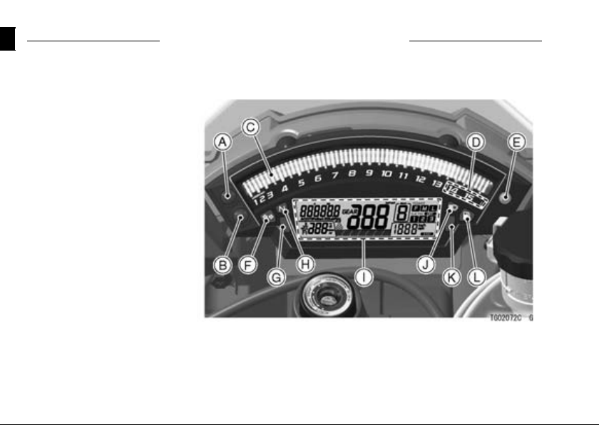
Meter Instruments
A. Upper Button
B. Lower Button
C. Tachometer (with Sh ift-Up
Indicator)
D. Red Zone
E. Ambient Brightness
Sensor
F. Turn Signal Indicator Lig ht
G. Warning Indicator Light
(Red)
H. Neutral Indicator Light
I. Multifunction Meter
J. High Beam Indicator Light
K. Warning Indicator Light
(Yellow)
L. Fuel Level Warning
Indicator Light
GENERAL INFORMATION
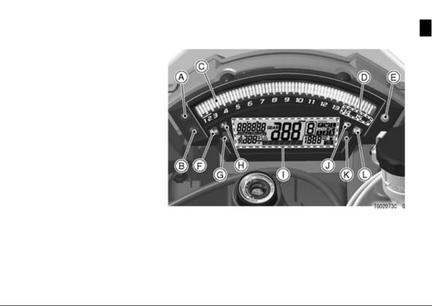
(For models equipped with KIBS*)
A. Upper Button
B. Lower Button
C. Tachometer (with S hift-Up
Indicator)
D. Red Zone
E. Ambient Brightness
Sensor
F. Turn Signal Indicator Light
G. Warning Indicator Light
(Red)
H. Neutral Indicator Light
I. Multifunction Meter
J. High Beam Indicator Light
K. Warning Indicator Light
(Yellow)
L. ABS Indicator Lig ht
KIBS*: Kawasaki Intelligent anti-lock Brake System
GENERAL INFORMATION 21
22 GENERAL INFORMATION
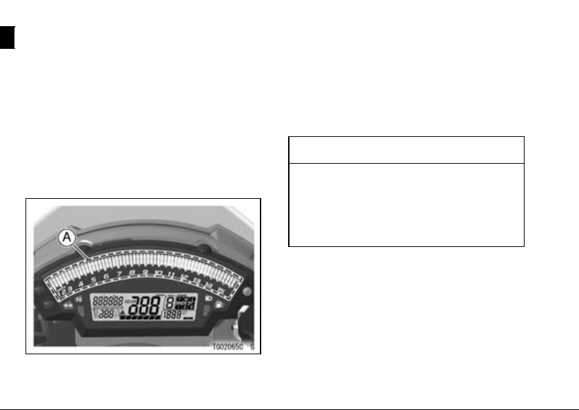
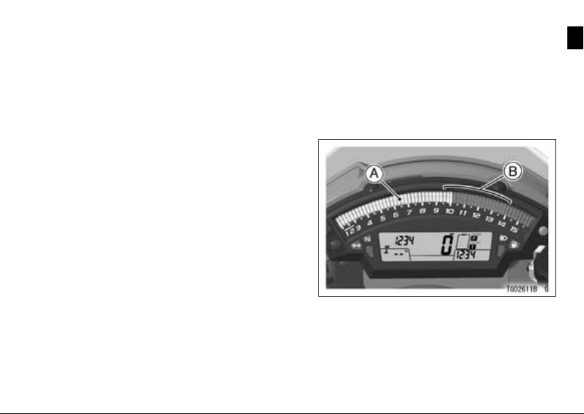
Tachometer
The tachometer shows the engine
speed in revolutions per minute (r/min,
rpm).
On the right side of the tachometer
face is a portion called the “red zone”.
Engine r/min (rpm) in the red zone is
above maximum recommended engine
speed and is also above the range for
good performance.
A. Tachometer
When the ignition switch is turned to
“ON”, the tachometer LED segments
are blinks for a few seconds then goes
off. If the tachometer does not operate
correctly, have it checked by an authorized Kawasaki dealer.
NOTICE
Engine r/min (rpm) should not
be allowed to enter the red zone;
operation in the red zone will
overstress the engine and may
cause serious engine damage.
Shift-up Indicator -
Theshift-upindicatorcanbesetto
tachometer LED segments blinks at the
desired engine speeds. This indicator
is used to inform the rider when it is time
to shift to the next higher gear.
GENERAL INFORMATION 23
This shift-up indicator is used to inform to the rider when it is time to shift
to the next higher gear with blinking the
tachometer LED segments.
Theshift-upindicatorcanbeusedin
closed course competition. Do not use
the shift-up indicator during everyday
riding.
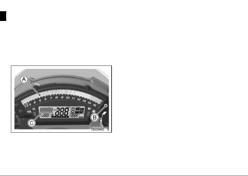
Shift-up Indicator Setting -
Theshift-upindicatorhasthree
modes, light off, fast blinking or slow
blinking. The shift-up indicator timing
canbeadjustedbetween9500r/min
(rpm) and 14 000 r/ min (rpm).
A. Tachometer
B. Adjustable Range
To select a shift-up indicator mode or
adjust the shift-up engine spe ed setting in the tachometer, do the followings
while the engine is a t a stop.
24 GENERAL INFORMATION
Turn the ignition switch to “ON”.
•
Push the upper and lower buttons si-
•
multaneously for more than 2 seconds. The previous shift-up engine
speed setting will be displayed in the
tachometer.
A. Upper Button
B. Lower Button
C. Shift-up Engine Speed
To change the shift-up indicator
•
mode, push the upper button and the
illumination of tachometer segment
will shift between Light ON (shift-up
indicator d eactivates), Fast Blinking and Slow Blinking. The shift-up
engine speed can only be adjusted
when the segments are blinking.
To adjust the shift-up engine speed,
•
push the lower button and the shift
-up engine speed timing advances in
250 r/min (rpm) increments up to 14
000 r/min (rpm). Once the reading
reaches at 14 000 r/min (rpm) while
advancing, it returns to 9 500 r/ min
(rpm) and begins advancing.
To complete the adjustment, push
•
the upper and lower buttons simultaneously for more than 2 s econds.
The tachometer now operates normally.
To adjust the tachometer brightness,
•
push the upper button for more than
2 seconds (See Instrument Display
Brightness Adjustment).
GENERAL INFORMATION 25
WARNING
Failing to properly observe the
road ahead increases the chance
of an accident. Do not concentrate on the shift-up indicator by
taking your eyes off the road,
observe using peripheral vision. When shifting down to a
lower gear, do not shift at such a
high speed that the engine r/min
(rpm) jumps excessively. Not
onlycanthiscauseenginedamage, but the rear wheel may skid
and cause an accident. Downshifting should be done below 5
000 r/min (rpm) for each gear.
NOTE
Pushing and holding the lower button
○
advances the shift–up engine speed
continuously.
The data are maintained even if the
○
battery is disconnected.
NOTICE
Engine r/min (rpm) should not
be allowed to enter the red zone;
operation in the red zone will
overstress the engine and may
cause serious engine damage.
26 GENERAL INFORMATION
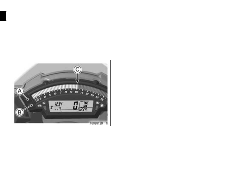
Instrument Display Brightness
Control
The brightness of the tachometer
LED segments and illumination of the
multifunction meter are controlled automatically depending on the ambient
brightness.
A. Tachometer
B. Ambient Brightness Sensor
C. Multifunction Meter
NOTE
Be careful not to cover the amb ien t
○
brightness sensor on the meter instrument while riding the motorcycle.
Instrument Display Brightness
Adjustment -
The brightness of the instrument display can be adjusted manually in three
levels while the motorcycle is at a stop.
While the shift-up indicator setting
•
mode, push the upper button for
more than 2 seconds. All tachometer LED segments are goes on.
Pushthelowerbuttontoselectthe
•
preferred brightness level.
To complete the adjustment, push
•
the upper and lower buttons simultaneously for more than 2 s econds.
The tachometer now operates normally.

To return to the shift up indicator set-
•
ting mode, push the upper button for
more than 2 seconds.
GENERAL INFORMATION 27
28 GENERAL INFORMATION
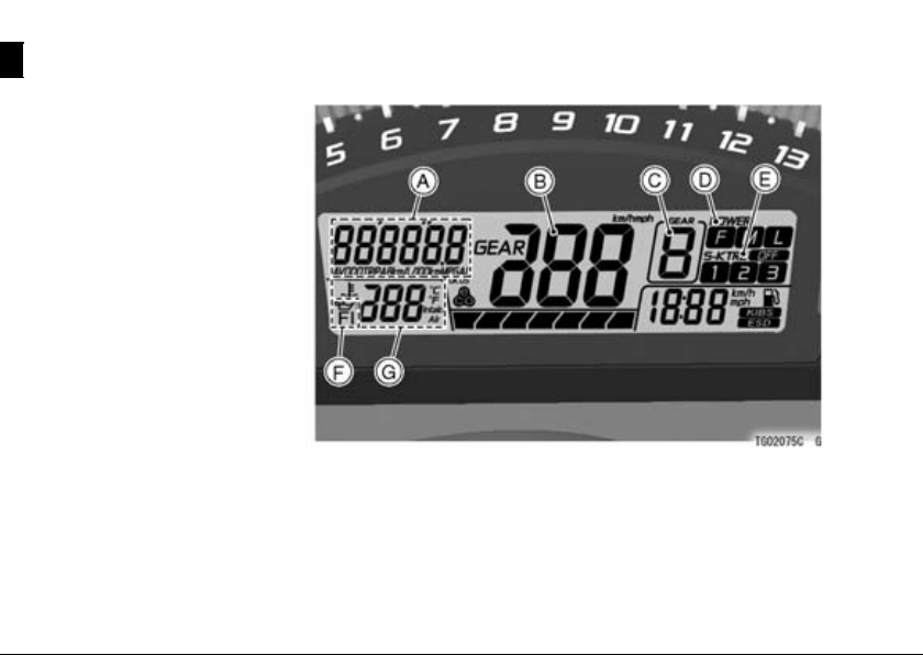
Multifunction Meter
A. Multifunction Display
-Odometer
-TripMeters
- Current Mileage
- Average Mileage
- Fuel consumption
- Stop Watch
B. Speedometer
C. Gear Position Indicator
D. Power Mode Indicator
E. S-KTRC Mode Indicator
F. Warning Symbols
G. Lap Counter/Coolant /
Intake Air Temperature
Meter
-LapCounter
- Coolant Temperature
- Intake Air Temperature
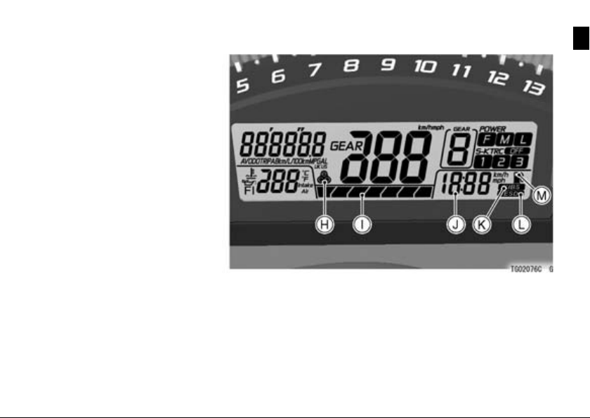
H. Economical Riding
Indicator
I. S-KTRC Level Indicator
J. Clock
K. KIBS Indicator (For the
models equipped with
KIBS)
L. Electronic Steering Damper
Indicator
M. Fuel Level Warning
Symbol (For the models
equipped with KIBS)
GENERAL INFORMATION 29
 Loading...