

Kawasaki JET MATE Service Manual
Kawasaki
~eT
4ILl77:
Watercraft
Service Manual
beerdart
I.
QUICK
R~FERENCE
GUIDE
,,
GENERAL
INFORMATION
FUEL
SYSTEM
ENGINE
LUBRICATION
SYSTEM
EXHAUST
SYSTEM
ENGINE
TOP
END
ENGINE
REMOVAL
AND
INSTALLATION
ENGINE
BOTTOM
END
COOLING
AND BILGE
SYSTEMS
DRIVE
SHAFT
PUMP
AND
IMPELLER
STEERING
HULL
ELECTRICAL
SYSTEM
STORAGE
APPENDIX
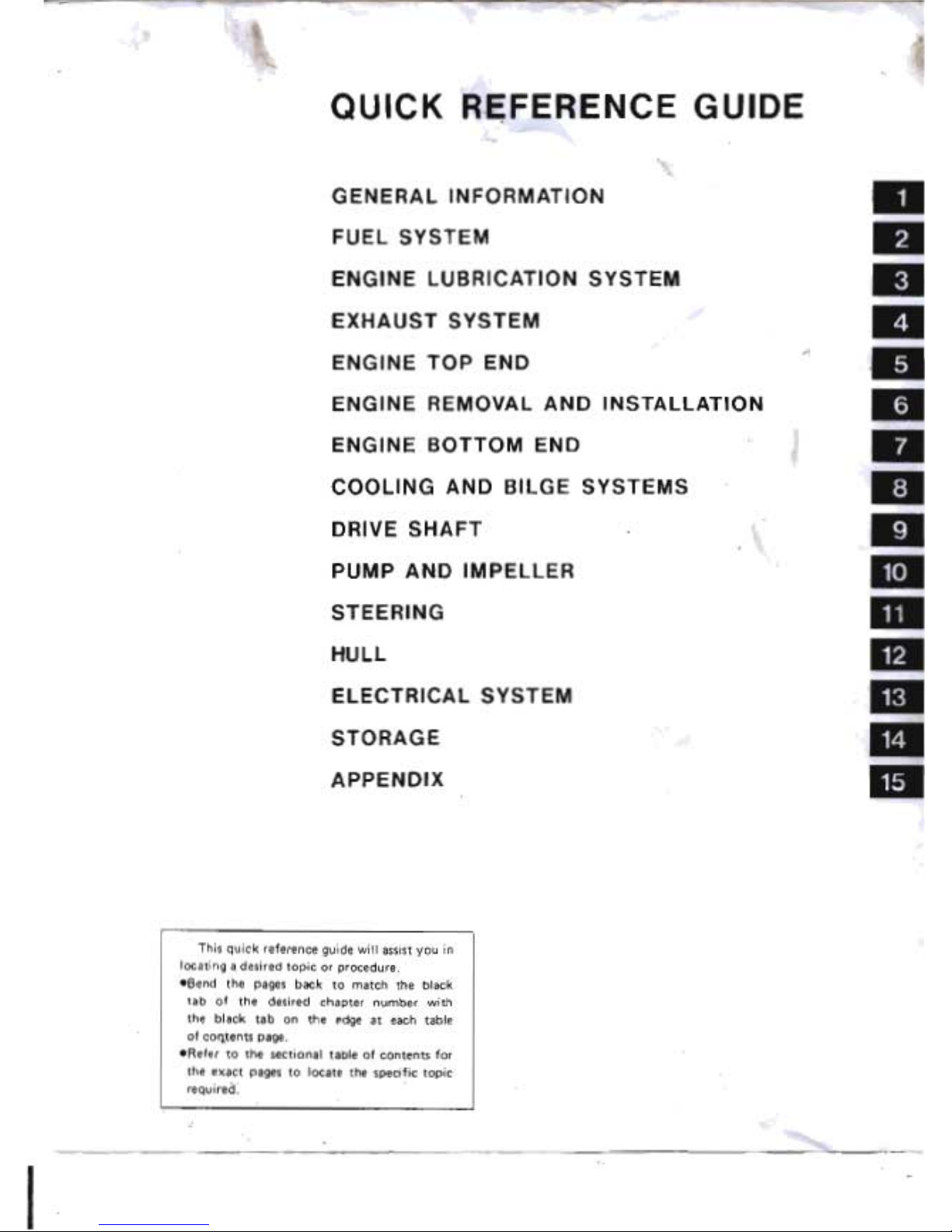
This
quick
reference guide will assist you
in
locating
a,
desired
topic
or
procedure.
-Bend
the
pages back
to
match
the
black
tab
of
the
desired
chapter
number
with
the
black
tab
on
the
edge
at
each table
of
cOlltents page.
-Refer
to
the
sectional table of
contents
for
the exact pages
to
locate
the
specific topic
required:
.'
beerdart

Kawasaki
Watercraft
Service Manual
All
rights reserved.
No
parts
of
this
publication
may
be
reproduced,
stored
in a retrieval system,
or
transmitted
in any form
or
by
any means, electronic mechanical
photocopying,
recording
or
otherwise,
without
the
prior
written permission
of
Quality Assurance Department/Consumer Products Group/Kawasaki Heavy Industries,
ltd.,
Japan.
No
liability can be accepted for any inaccuracies
or
omissions
in
this pUblication, although every
possible care has been taken
to
make it
as
complete and accurate as possible.
The right
is
reserved
to
make
changes
at any time
without
prior
notice
and
without
incurring
an
obligation
to
make such changes
to
products manufactured previously. See your watercraft dealer
for
the
latest information
on
product
improvements incorporated after this publication.
All information contained
in
this publication
is
based
on
the
latest
product
information available
at
the
time of publication. Illustrations and photographs
in
this publication are intended for reference
use only and may
not
depict
actual model
component
parts.
© Kawasaki
Heavy
Industries, Ltd. 1988, 1989, 1992
Third Edition
(3):
Sap. 10, 1997
(KJ
beerdart
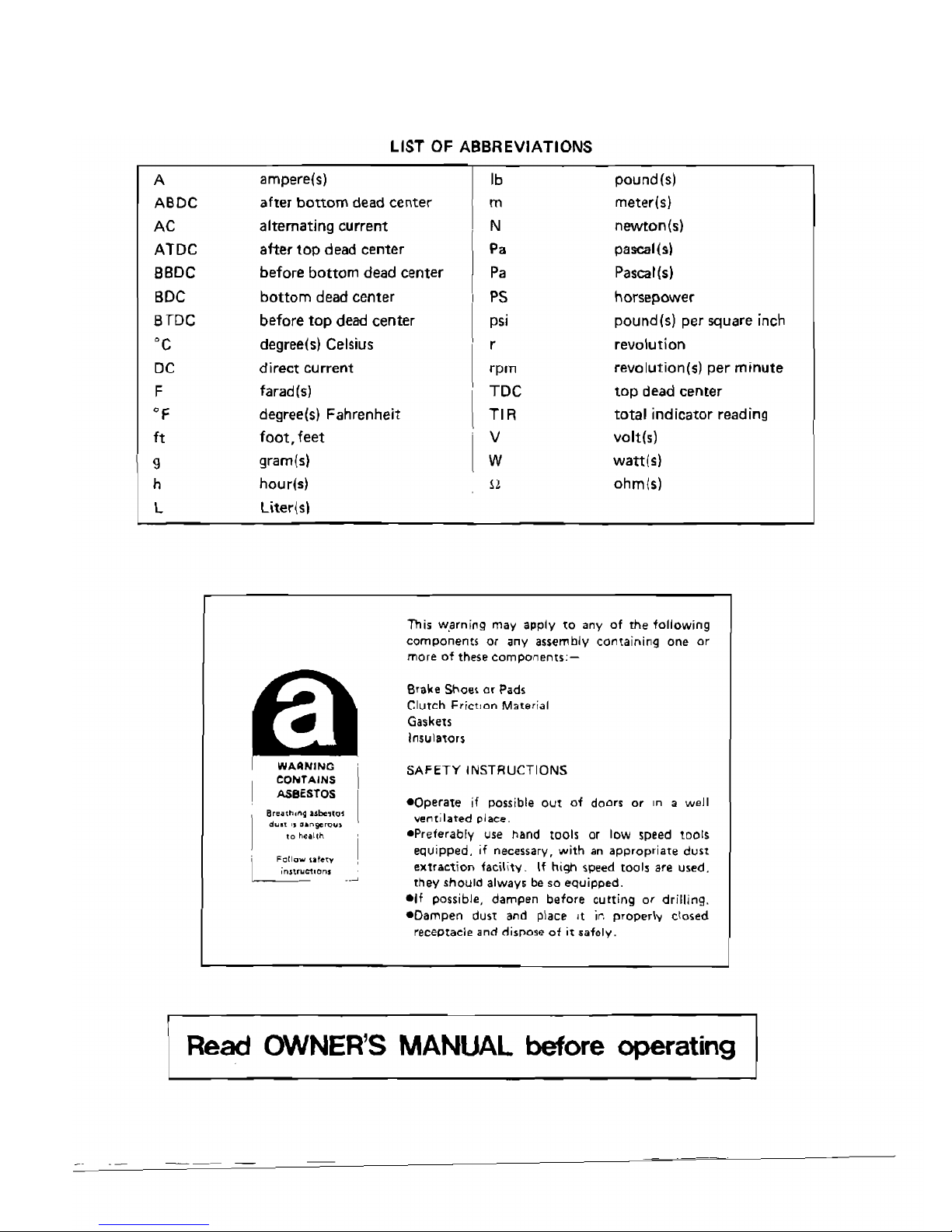
LIST
OF
ABBREVIATIONS
A
ampere{s)
Ib
pound(s)
ABDC
after
bottom
dead center m meter{s)
AC alternating current N
newton(s)
ATDC
after
top
dead center
P.
pascal(s)
BBDC before
bottom
dead center
Pa
Pascal(s)
BDC
bottom
dead center
PS
horsepower
8TDC
before top dead center
psi
pound(s) per square inch
'c
degree(s}
Celsius
r revolution
DC
direct
current
rpm
revolution(s)
per
minute
F
farad
(5)
TDC
top
dead center
'F
degree(s) Fahrenheit
TIR
total indicator reading
It
foot,
feet
V
volt(s)
9
gram(s)
W
wan(s}
h
hourIs)
!l
ohmlsl
L
Liter(s!
Bro"h,ng ..be'l<>'
d",", " ••
"go",,,.,
to
heallh
FOil""
,alew
;nn'uC1,on,
This w.arning may apply
to
any
of
the
following
components or any assembly containing one
or
more
of
these
components:-
Brake
Shoe~
or
Pads
Clutch
Friction
Material
Gaskets
Insulators
SAFETY
INSTRUCTIONS
-Operate
if
possible
OUt
of
doors
or
in
a well
ver1tilated place.
.Preferably use hand
tools
or low speed
tOOls
equipped.
if necessary.
with
an
appropriate
dust
extraction
facility.
If
high
speed
tools are used.
they
should
always be
so
equipped.
elf possible,
dampen
before
cutting
or
drilling.
-Dampen
dust
and
place it
ir.
properly
closed
receptaclE! and dispose
of
it
safely.
Read OWNER'S
MANUAL
before operating
beerdart
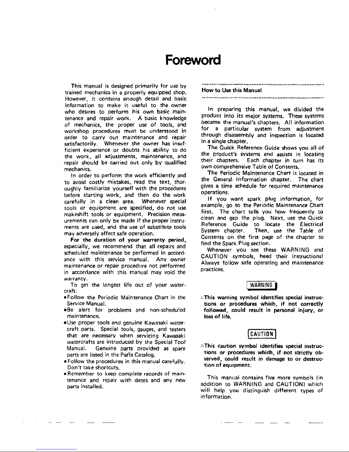
Foreword
•
This
manual
is
designed primarily for use
by
trained mechanics
in a properly
equipped
shop.
However, it contains enough detail
and
basic
information
to
make
it useful
to
the
owner
who desires
to
perform his own basic main-
tenance and repair work. A basic knowledge
of
mechanics, the proper
use
of
tools,
and
workshop
procedures must be understood in
order
to
carry
out
maintenance and repair
satisfactorily. Whenever
the
owner
has insuf-
ficient experience
or
doubts his
ability
to
do
the
work,
alt adjustments, maintenance,
and
repair should be carried
out
only
by
qualified
mechanics.
In order
to
perform the work efficiently
and
to
avoid costly mistakes, read the text, thor-
oughly familiarize yourself
with
the procedures
before
starting
work,
and
then
do
the
work
carefully in a clean area. Whenever special
tools
o.r
equipment
are specified,
do
not
use
makeshIft
tools
or
equipment.
Precision meas-
urements
can
only
be
made
if
the
proper
instru-
ments are used,
and
the
use
of
substitute
tools
may adversely
affect
safe
operation.
For
the
duration
of
your
warranty
period
especially. we
recommend
that
all repairs
and
scheduled
maintenance
be
performed
in accord-
ance with
this
service manual.
Any
owner
maintenance
or
repair
procedure
not
performed
in
accordance
with
this
manual may void
the
warranty.
To
get
the
longest life
out
of
your
water-
craft:
_Follow
the
Periodic
Maintenance
Chart
in
the
Service Manual.
eBe
alert
for
problems
and
non-scheduled
maintenance.
eUse
proper
tools
and
genuine
Kawasaki
water·
craft
parts. Speciai
tools,
gauges,
and
testers
that
are necessary
when
servicing KawasakI
watercrafts
are
introduced
by
the
Special
Tool
Manual.
Genuine
parts
provided as spare
parts are listed
in
the
Parts
Catalog.
e Follow
the
procedures
in this manual carefully.
Don't
take
shortcuts.
e
Remember
to
keep
complete
records
of
main-
tenance
and
repair
with
dates
and any
new
parts installed.
..................................................................
How
to
Use
this
Manual
............................................................................
In preparing
this
manual,
we
divided
the
product
into
its
major
systems.
These
systems
became
the
manual's
chapters.
All
information
for
a
particular
system
from
adjustment
through
disassembly
and
inspection
is
located
in a single
chapter.
The
Quick
Reference
Guide
shows
you
all
of
the.
product's
systems
and
assists in locating
theIr
chapters.
Each
chapter
in
turn
has its
own
comprehensive
Table
of
Contents.
The
Periodic
Maintenance
Chart
is
located
in
the
General
Information
chapter.
The
chart
gives a
time
schedule for required
maintenance
operations.
If
you
want
spark
plu.g
information,
for
example,
go
to
the
Periodic Maintenance
Chart
first. The
chart
tells
you
how frequently
to
clean
and gap
the
plug.
Next,
use
the
Ouick
Reference
Guide
to
locate
the
Electrical
System
chapter.
Then,
use
the
Table
of
Contents
on
the
first page
of
the
chapter
to
find
the
Spark
Plug section.
Whenever
you
see
these
WARNING
and
CAUTION
symbols,
heed
their
instructions!
Always
follow
safe
operating
and
maintenance
practices.
I
WARNING
I
oThis
warning
symbol
identifies special
instruc·
tions
or
procedures
which,
if
not
correctly
followe~,
could
result
in personal injury,
or
loss
of
life.
(C~UT(O]]
oThis
caution
symbol
identifies special
instruc.
tions
or
procedures
which,
if
not
strictly
ob·
served, could
result
in
damage
to
Or
destruc·
tion
of
equipment.
This
manual
contains
five
more
symbols
(in
addition
to
WARNING and CAUTION)
which
will help
you
distinguish
different
types
of
information.
beerdart
•
NOTE
o
This
note symbol indicates points
of
particular
interest
for
more
efficient
and convenient
operation.
• Indicates a procedural step
or
work
to
be
done.
olndicates a procedural sub-step
or
how to
do
the work
of
the procedural step it follows.
It also precedes
the
text
of
a WARNING,
CAUTION, or NOTE.
*Indicates a conditional step or what action
to
take based
on
the
results
of
the
test
or
inspec-
t;on
in
the
procedural step or sub-step
it follows.
?Indicates
a conditional sub-step
or
what
action to
take
based upon
the
results
of
the
conditional
step
it follows.
In
most
chapters
an exploded
view
illustra-
tion of the system components follows
the
Table
of
Contents.
In
these illustrations you
will
find
the
instructions indicating which
parts
require specified tightening
torque,
oil, grease
or
a locking
agent
during assembly.
beerdart
GENERAL
INFORMATION
1-1
•
GENERAL INFORMATION
Table of Contents
Before
Servicing
. 1-2
Model Identification _ ,
..
1-5
General Specification .
1-6
Periodic Maintenance Chart ,
..
1-7
Torque
and
Locking
Agent
.
1-8
Cable Routing .
1-
1Q
beerdart
1-2
GENERAL INFORMATION
Before Servicing
Before starting
to
service a motorcycle, careful reading
of
the
applicable section
is
recommended
to
eliminate unnecessary work. Photographs, diagrams, notes, cautions, warnings, and detailed des-
criptions have
been
included wherever necessary. Nevertheless, even a detailed
account
has limita-
tions, a certain
amount
of
basic knowledge
is
also required for successful work.
Especially note the following:
(1) Adjustments
Adjustments shall
be
made
in
accordance with
the
Periodic Maintenance Chart or whenever
troubleshooting
or
presence
of
symptoms indicate
that
adjustments may
be
required. Whenever
running
of
the
engine
is
required
during
maintenance
it
is
best
to
have
the
watercraft
in water,
000
not
run
the
engine
without
cooling
water
supply
for
more
than
15
seconds
or
severe engine and
exhaust
system
damage will occur,
121
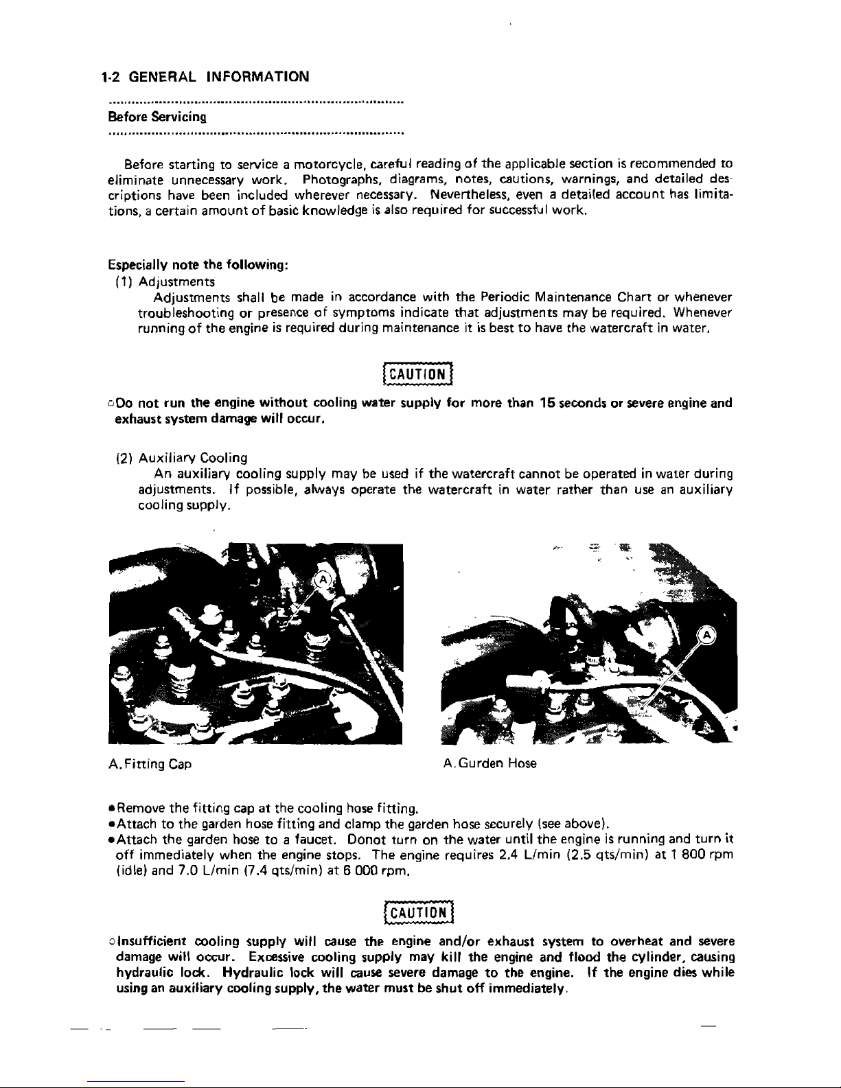
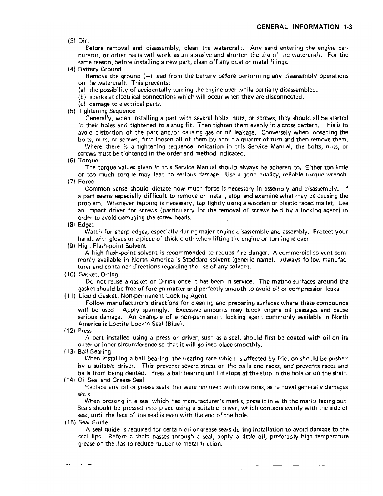
Auxiliary Cooling
An auxiliary cooling supply
may
be used
if
the
watercraft
cannot
be
operated
in
water
during
adjustments.
If possible, always
operate
the
watercraft
in
water
rather
than
use
an auxiliary
cooling
supply,
A. Fitting Cap
A.Gurden
Hose
_Remove
the
fitting
cap
at
the
cooling hose fitting.
-Attach
to
the
garden hose fitting and clamp
the
garden
hose
securely (see above).
_Attach
the
garden hose
to
a faucet.
Donat
turn
on
the
water
until
the
engine
is
running and
turn
it
off
immediately
when
the
engine stops.
The
engine requires
2:.4
Llmin
(2.5
qts/min)
at 1 800
rpm
(idle) and
7.0
Llmin
(7.4
qts/min)
at 6 000
rpm,
olnsufficient
cooling
supply
will cause
the
engine
and/or
exhaust
system
to
overheat
and
severe
damage
will
occur.
Excessive cooling
supply
may kill
the
engine
and
flood
the
cylinder, causing
hydraulic lock.
Hydraulic
lock will cause severe
damage
to
the
engine. If
the
engine dies while
using an auxiliary cooling
supply,
the
water
must
be
shut
off
immediately.
beerdart
GENERAL INFORMATION
1·3
(31
Dirt
Before removal and disassembly. clean the watercraft. Any sand entering
the
engine car-
buretor,
or
other
parts will work as an abrasive and
shorten
the
life
of
the
watercraft.
For
the
same reason, before installing a new part, clean
off
any
dust
or metal filings.
(4)
Battery
Ground
Remove the ground
(-I
lead from
the
battery before performing any disassembly operations
on
the
watercraft. This prevents:
(a)
the possibility
of
accidentally turning the engine over while partially disassembled.
(b) sparks
at
electrical connections which
will
occur
when
they
are disconnected.
(e) damage
to
electrical parts.
(5) Tightening Sequence
Generally. when installing a
part
with several bolts, nuts,
or
screws, they should all be started
in
their holes and tightened
to
a snug fit. Then tighten them evenly
in
a cross pattern. This
is
to
avoid distortion
of
the
part
and/or
causing gas
or
oil leakage. Conversely
when
loosening the
bolts, nuts, or screws, first loosen
all
of
them by
about a quarter
of
turn
and
then
remove them.
Where there
is
a tightening sequence indication
in
this Service Manual,
the
bolts, nuts,
or
screws must be tightened
in
the
order and method indicated.
(6) Torque
The torque values given
in
this Service Manual should always be adhered to. Either
too
little
or
too
much
torque
may lead
to
serious damage.
Use
a good quality, reliable
torque
wrench.
(7) Force
Common sense should
dictate
how much force
is
necessary
in
assembly and disassembly.
If
a part seems especially difficult
to
remove
or
install, stop and examine
what
may be causing the
problem. Whenever tapping
is
necessary, tap lightly using a wooden
or
plastic faced mallet.
Use
an
impact driver for screws (particularly for the removal
of
screws held
by
a locking agent)
in
order to avoid damaging the screw heads.
181
Edge,
Watch
for
sharp edges, especially during major engine disassembly and assembly. Protect your
hands with gloves
or
a piece
of
thick cloth when lifting
the
engine
or
turning it over.
(9)
High
Flash-point Solvent
A high fla$h-point solvent
is
recommended
to
reduce fire danger, A commercial solvent com-
monly available
in
North America
is
Stoddard solvent (generic name). Always follow manufac-
turer
and container directions regarding the use
of
any solvent.
(1OJ
Gasket, O-ring
Do
not
reuse a gasket
or
O-ring once it has been
in
service_
The
mating surfaces around the
gasket should
be
free
of
foreign
matter
and perfectly
smooth
to
avoid oil
or
compression leaks.
(11) Liquid Gasket, Non.permanent Locking Agent
Follow manufacturer's directions for cleaning and preparing surfaces
where
these compounds
will be used, Apply sparingly. Excessive amounts may block engine oil passages and cause
serious damage.
An
example
of
a non-permanent locking agent commonly available
in
North
America'is Loctite Lock'n Seal (Blue).
{12) Press
A
part
installed using a press or driver, such
as
a seal, should first
be
coated
with
oil on its
outer or inner circumference so
that
it will
go
into place smoothly.
{13)
Bal!
Bearing
When installing a ball bearing, the bearing race which
is
affected by friction should
be
pushed
by a suitable driver. This prevents severe stress on the balls and races, and prevents races and
balls from being
dented,
Press a ball bearing until it
stops
at
the
stop
in
the hole
or
on
the
shaft.
(14)
Oil
Seal and Grease Seal
Replace any oil
or
grease seals
that
were removed with new ones,
as
removal generally damages
seals.
When pressing
in
a seal which has manufacturer's marks, press it
in
with
the
marks facing out,
Seals should be pressed into place using a suitable driver, which contacts evenly with
the
side of
seal, until the face of the seal
is
even with
the
end
of
the
hole.
(15) Seal Guide
A seal guide
is
required for certain oil or grease seals during installation
to
avoid damage
to
the
seal lips. Before a shaft passes through a seal, apply a little oil, preferably high temperature
grease on
the
lips
to
reduce rubber to metal friction.
beerdart
1-4
GENERAL INFORMATION
(16) Circlip, Retaining Ring,
Cotter
Pin
Replace any circlips,
cotter
pins and retammq rings
that
were removed with new ones, as
removal weakens and deforms them. When installing circlips and retaining rings,
take
care to
compress
or
expand
them
only
enough
to
install
them
and
no
more.
(17)
Lubrication
Engine
wear
is
generally
at
its
maximum
while
the
engine
is
warming
up
and
before
all
the
rubbing
surfaces
have
an
adequate
lubricative film. During
assembly,
oil
or
grease {whichever
is
more suitable) should
be
applied
to
any rubbing surface which has lost its lubricative film. Old
grease and dirty oil should
be
cleaned off. Deteriorated grease has lost its lubricative quality and
may
contain
abrasive foreign particles.
Don't
use just any oil
or
grease. Some oils and greases
in
particular should be used
only
in
certain applications and may
be
harmful if used
in
an application
for
which
they
are
not
intend
ed.
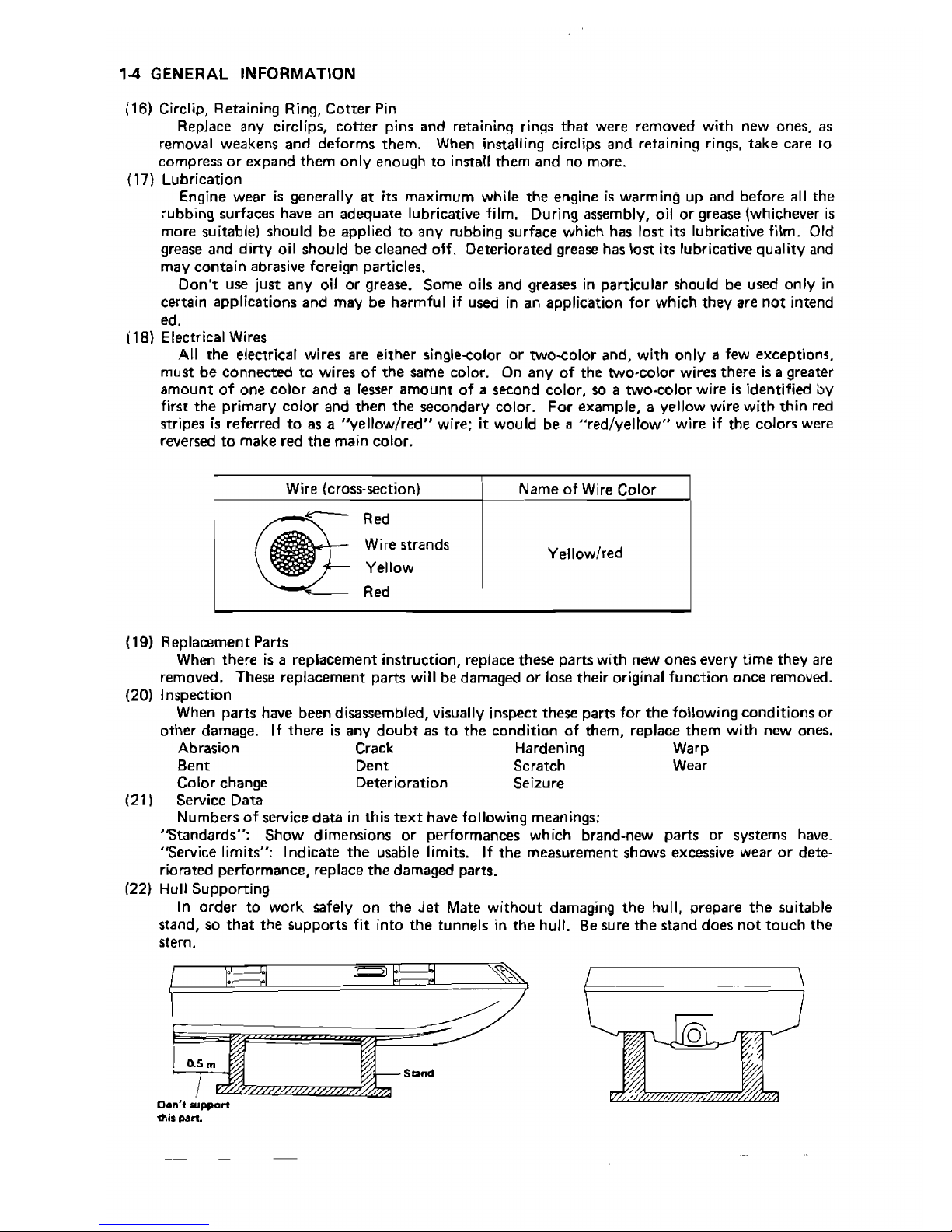
(18) Electrical Wires
All
the
electrical wires are either single-color
or
two-color and,
with
only a few exceptions,
must
be
connected
to
wires
of
the
same color.
On
any
of
the
two-color wires
there
is
a greater
amount
of
one
color
and a lesser
amount
of
a second color, so a two-color wire
is
identified by
first
the
primary
color
and
then
the
secondary color.
For
example, a yellow wire
with
thin red
stripes
is
referred
to
as a
"yellow/red"
wire; it would be a "red/yellow" wire if
the
colors were
reversed
to
make red
the
main color.
Wire (cross-section)
Name
of
Wire Color
@;
Red
Wire strands
Yellow
Red
Yellow/red
(19) Replacement Parts
When there
is
a replacement instruction, replace these parts with new
ones
every
time
they
are
removed, These replacement parts
will be damaged
or
lose their original
function
once removed.
(20) Inspection
When parts have been disassembled, visually inspect these parts
for
the
following conditions
or
other damage. If
there
is
any
doubt
as
to
the
condition
of
them, replace
them
with new ones.
Abrasion Crack Hardening Warp
Bent Dent Scratch Wear
Color change Deterioration Seizure
(211
Service Data
Numbers
of
service
data
in
this
text
have following meanings;
"Standards":
Show
dimenSions
or
performances which brand-new parts or systems have.
''Service limits": Indicate
the
usable limits. If
the
measurement shows excessive wear
or
dete-
riorated performance, replace
the
damaged parts.
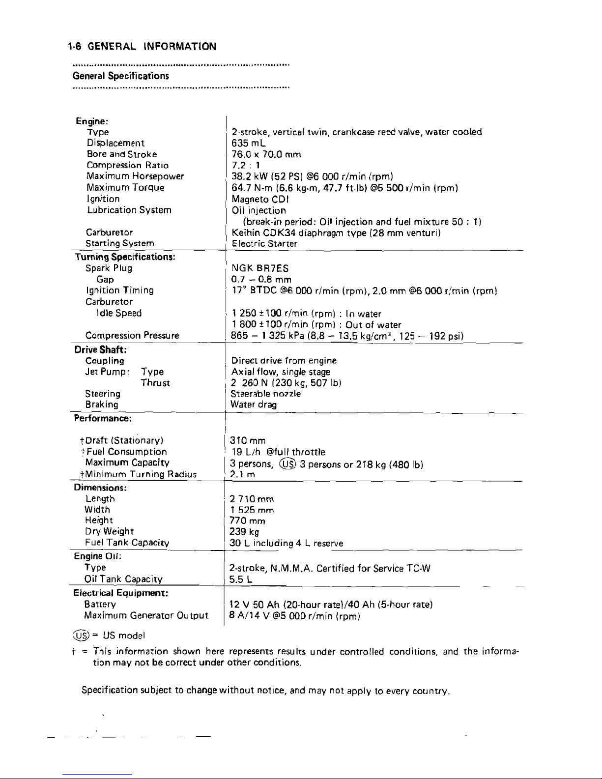
(22)
Hull
Supporting
In
order
to
work safely on
the
Jet
Mate
without
damaging
the
hull, prepare
the
suitable
stand, so
that
the
supports fit into
the
tunnels
in
the
hull.
Be
sure
the
stand does
not
touch
the
stern.
[
,)
O.5m
s~""
Don't
suplJOn
this
paM.
beerdart

,
GENERAL INFORII'IATION
'-5
Model Identification
JB650-A1
_/
JB650-A2
/
-
-------~--=;;.;..
JB65Q.A3
,
.
•
V!M¥iSB!&'
JB65Q.A4
•
_..:
.
/
. ,
-0
0%
i",,,-,,
"
_'
__
·~yCw;
,
--.
~--'iL
------_
...
beerdart
1·6 GENERAL
INFORMATION
............
- - - .
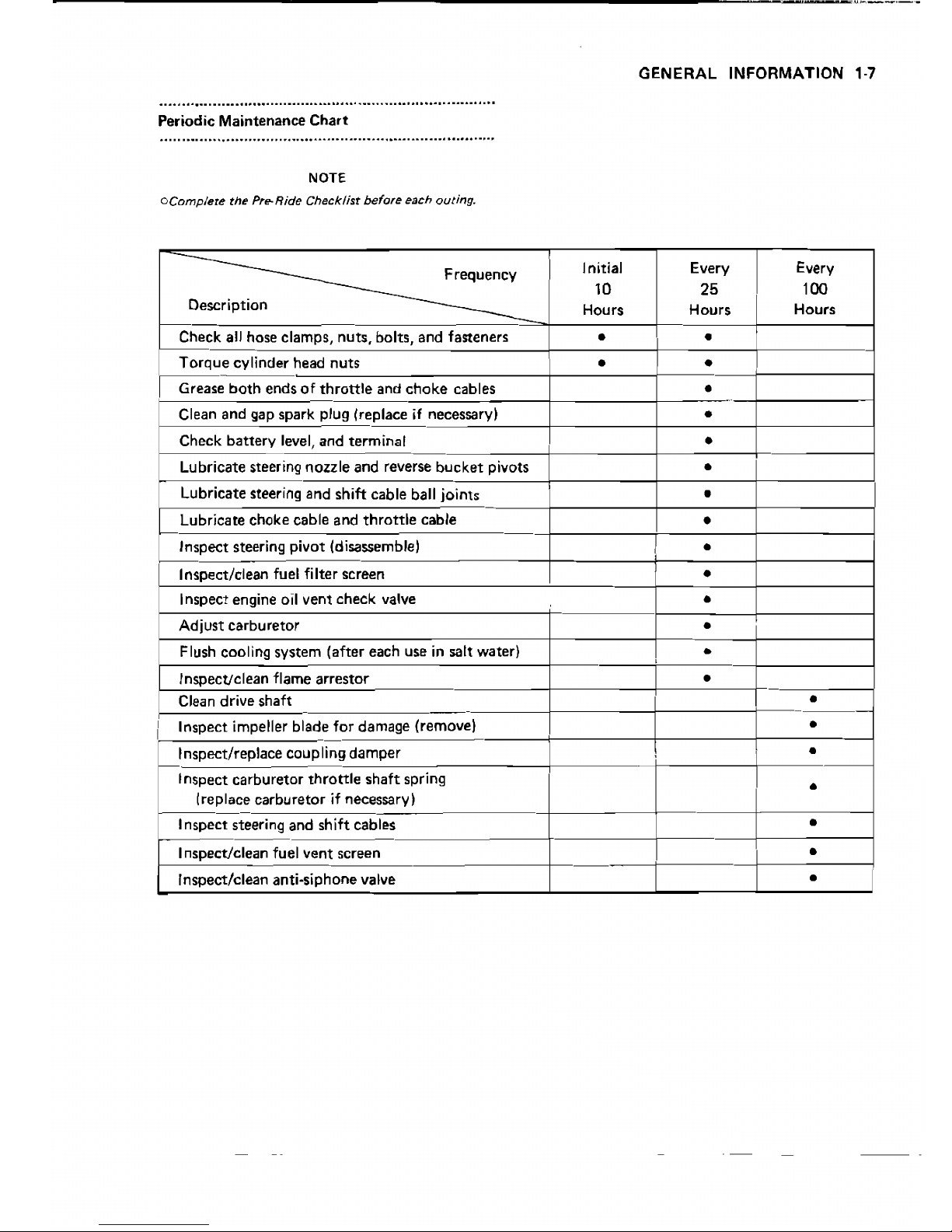
General Specifications
Engine:
Type
Displacement
Bore and
Stroke
Compression Ratio
Maximum Horsepower
Maximum
Torque
Ignition
Lubrication System
Carburetor
-=_,S:.':::"_,":::i
n~g,-,-S'cyst~e_,mc-~
Turning Specifications:
Spark Plug
Gap
Ignition Timing
Carburetor
Idle Speed
Compression Pressure
I2-stroke, vertical twin, crankcase reed valve, water cooled
635
mL
76.0 x 70.0 mm
7.2,
,
38.2
kW
152
PSI
@6
000 r/m!n Irpml
64.7
N-m
16.6 kg·m. 47.7 ft-lb)@5
500
r/min (rpm)
1
Magneto COl
I
Oil
injection
(break-in period:
Oil
injection and fuel mixture
50;
1)
I
Keihin
COK34
diaphragm
type
(28
mm
venturi)
~j
Eleetr ic
Sta
rteT
I
NGK
BR7ES
1°,7
-0.8
mm
111'"
BTDC
@6
000
r/min
(rpm), 2.0 mm
@6
000
r/min
(rpm)
' 1
250 ±100
({min (rpm) : In water
,
800
± 100
r/min
(rpm) :
Out
of water
I
865
-1325
kPa
(8.8
-13.5
kg/em;:,
125_-_'"'9:::2'-p:::s:::i)=--
_
Driv-e~S'ch-aft~-;
------~-I
.
Ccupling , Direct drive from engine
Jet
Pump:
Type
IAxial flow, single stage
Thrust , 2
260
N 1230
kg,
507
Ib)
Steering
Steer~b\e
n07Zle
Braking
I
Water drag
Performance:
I
toraft
(Stationary)
1310
mm
+Fuel Consumption ' 19
LJh
@fullthrottle
Maximum Capacity
13
persons, @ 3 persons
or
218
kg
(480
Ib)
-='c"
M=;n'-im~u'-m'--T-="'-r:::n·:::'n"gc:R'-.=d=i::.u::.'--lc'2::: ...:1-'m'-----~
~
_
Dimensions:
Length
2710mm
'I
Width 1
525
mm
Height
1770
mm
Dry Weight
239
kg
Fuel
Tank
Capacity
30
L including 4 L reserve
Engine
Oil:
Type
2-stroke,
N.M.M.A. Certified
for
Service
TC-W
Oil Tank Capacity
5.5 L
Electrical
Equipment:
Battery
'2 V 50
Ah (20-hour rate)/40
Ah
(5-hour rate)
Maximum Generator
Output
8
A/14
V@5000r/min
(rpm)
1
@:::
US
model
t
:::
This information shown here represents results under controlled conditions, and
the
informa-
tion may
not
be correct under
other
conditions.
Specification subject to change
without
notice, and may not apply to every country.
beerdart
._----------------------------------------_._--'.~~--"-'-
GENERAL INFORMATION
'-7
........................
- - - .
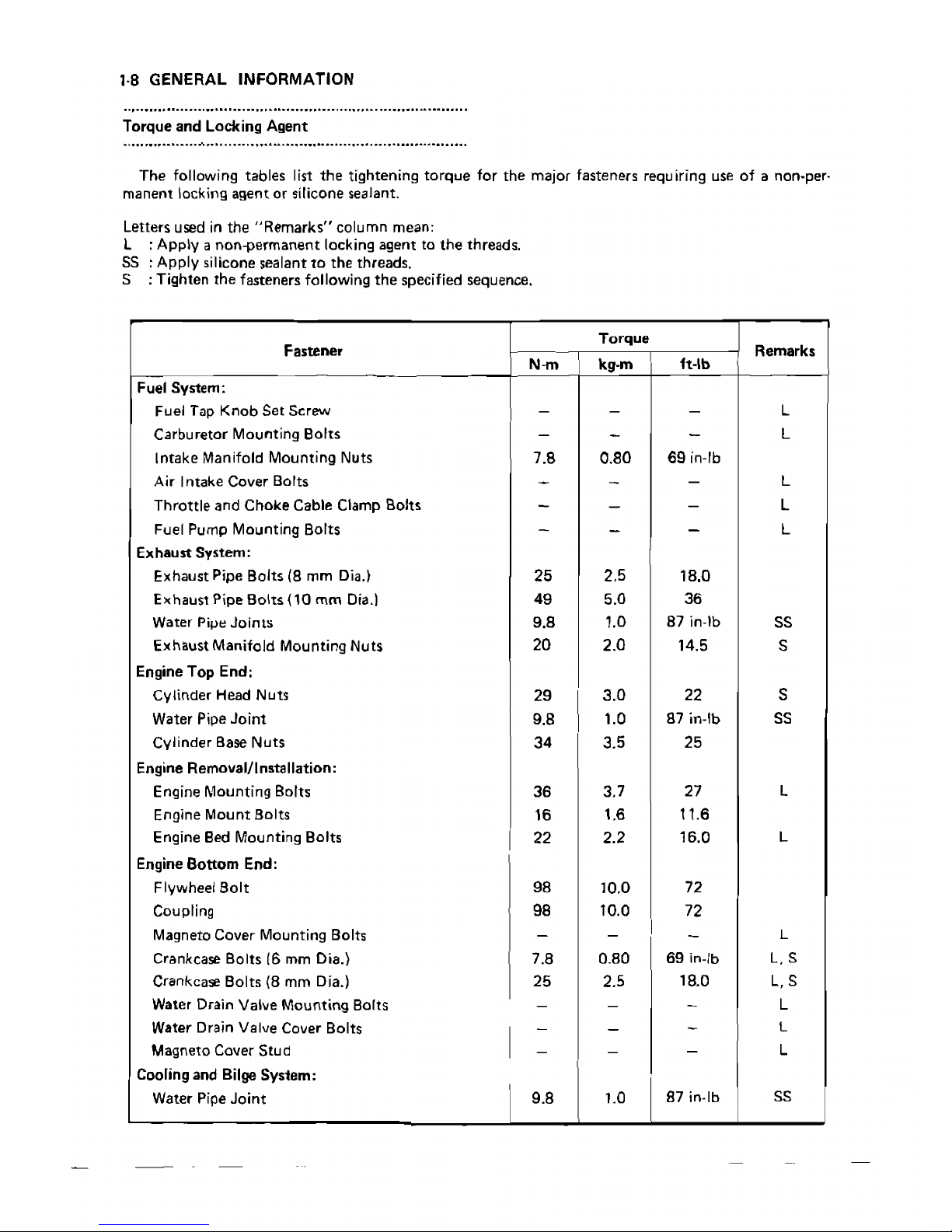
Periodic Maintenance
Chart
........................................................................
-
...
NOTE
oComp/et8
the Pre-Ride Checklist
before
each outing.
Frequency
Initial
10
Every
25
Every
100
Description
Hours
Hours
Hours
Check all hose clamps, nuts, bolts, and fasteners
• •
Torque
cylinder
head
nuts
• •
Grease
both
ends
of
throttle
and
choke
cables
•
..
Clean and gap spark
plug
(replace if necessary)
•
Check battery level, and terminal
•
Lubricate steering nOlzle and reverse bucket pivots
•
Lubricate steering and shift cable ball joints
•
Lubricate choke cable and
throttle
cable
•
Inspect steering pivot (disassemble)
•
Inspect/clean fuel filter screen
•
Inspect engine oil vent check valve
•
Adjust carburetor
•
Flush cooling system (after each use
in
salt water)
,
•
InspecUclean flame arrestor
Clean drive shaft
•
•
Inspect impeller blade
for
damage (remove)
•
Inspect/replace coupling damper
•
Inspect carburetor
throttle
shaft
spring
(replace carburetor if necessary)
•
Inspect steering and shift cables
•
Inspect/c1ean fuel vent screen
•
Inspect/clean anti-siphone valve
•
beerdart
1·8 GENERAL INFORMATION
..............................................................................
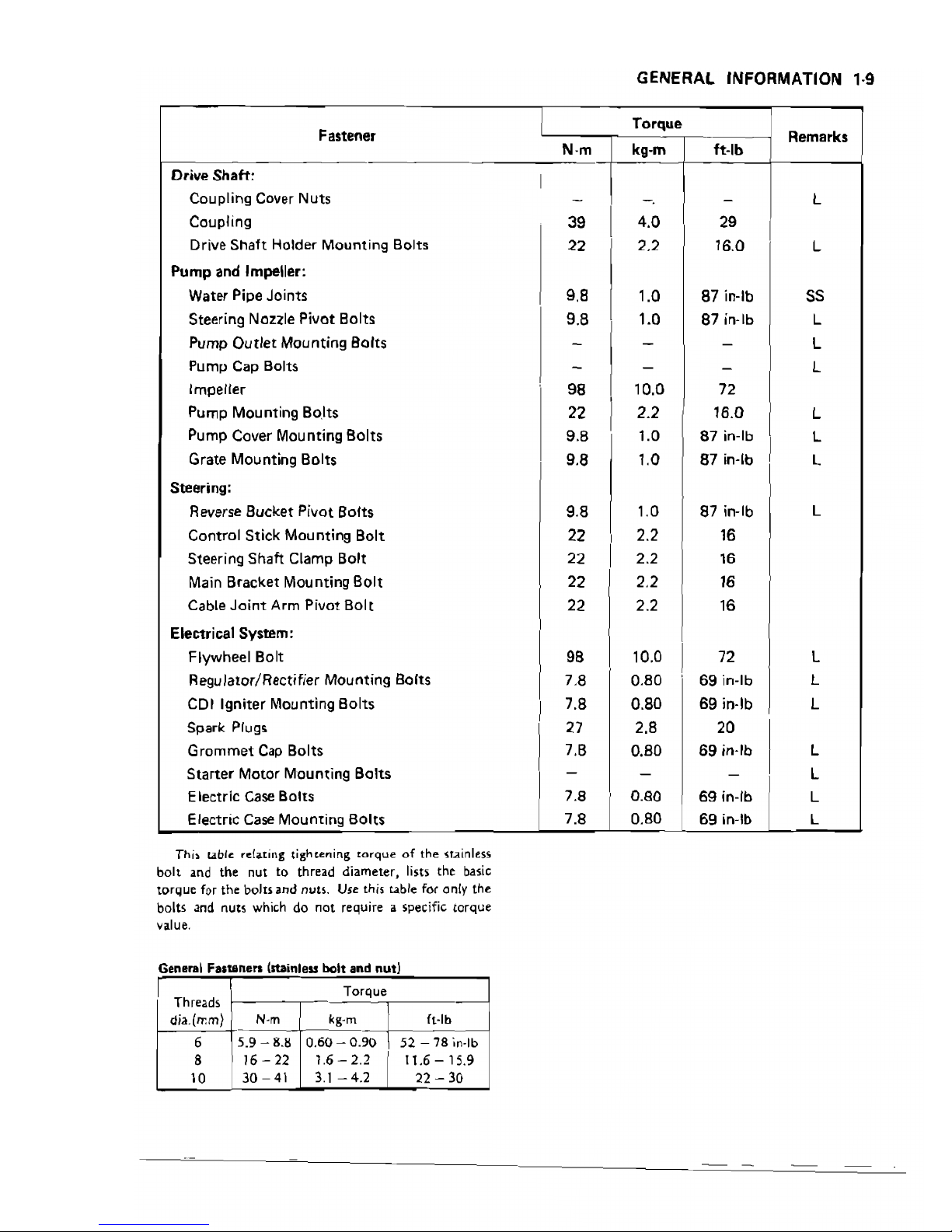
Torque and Locking Agent
.....................
-
'"
- .
The following tables list
the
tightening
torque
for
the
major fasteners requiring use
of
a non-per-
manent locking agent or silicone sealant.
Letters
used
in the
"Remarks"
column mean:
L : Apply a non-permanent locking agent to
the
threads.
55 :
Apply
silicone sealant
to
the threads.
S : Tighten
the
fasteners following
the
specified sequence.
Fastener
N·m
Torque
kg·m
ft·lb
Remarks
Fuel System:
Fuel Tap
Knob
Set
Screw
Carburetor Mounting Bolts
Intake Manifold Mounting Nuts
Air Intake Cover Bolts
-
-
7.8
-
-
-
0.80
-
-
-
69 in-Ib
-
L
L
L
Throttle and
Choke
Cable Clamp Bolts
- -
- L
Fuel Pump Mounting Bolts
Exhaust System:
Exhaust Pipe Bolts
(8
mm
Dia.~
Exhaust Pipe Bolts {10 mm Oia.!
Water Pipe
Joints
Exhaust Manifold Mounting Nuts
-
25
49
9.8
20
-
2.5
5.0
1.0
2.0
-
18.0
36
87
in~lb
14.5
L
55
5
Engine Top End:
Cylinder Head Nuts
Water Pipe
Joint
Cylinder Base Nuts
29
9.8
34
3.0
1.0
3.5
22
87
in-Ib
25
5
S5
Engine Removal/Installation:
Engine Mounting Bolts
Engine Mount Bolts
Engine Bed Mounting Bolts
36
16
22
3.7
1.6
2.2
27
11.6
16.0
L
L
Engine
Bottom
End:
Flywheel Bolt
Coupling
Magneto Cover Mounting Bolts
Crankcase Bolts
16
mm
Dia.}
Crankca~
Bolts (8 mm Dia.)
Water Drain Valve Mounting Bo(ts
Water Drain Valve Cover Bolts
98
98
-
7.8
25
-
-
10.0
10.0
-
0.80
2.5
-
-
I
72
72
-
69
in-Ib
18.0
-
-
L
L.S
L,5
L
L
Magneto Cover Stud
I
- -
-
L
Cooling and Bilge Sys1em:
Water Pipe
Joint
9.8
1.0
87 in-Ib
55
beerdart
GENERAL INFORMATION
'·9
Fastener
Torque
N·m
kg·m ft-Ib
Drive
Shaft:
I
Coupling Cover
Nuts
-
-.
-
Coupling
39
I
4.0
29
Drive
Shaft
Holder
Mounting
Bolts
22
2.2 16.0
Pump
and Impeller:
Water Pipe Joints
9.8
1.0
87 in-Ib
Steering Nozlle Pivot Bolts
9.8
1.0
87 in-lb
Pump
Outlet
Mounting Bolts
- -
-
Pump
Cap
Bolts
-
- -
Impeller
98
10.0 72
Pump
Mounting
Bo.!ts
22
I
2.2
16.0
Pump Cover
Mounting
Bolts
9.8
1.0
87
in-Ib
Grate
Mounting
Bolts
9.8
1.0
87 in-lb
Steering:
Reverse Bucket Pivot Bofts
9.8
1.0 87 in-Ib
Control Stick Mounting Bolt 22
I
2.2
16
Steering Shaft Clamp
Bolt
22 2.2
16
Main Bracket
Mounting
80lt
22
2.2
16
Cable
Joint
Arm
Pivot
Bolt
22 2.2
16
Electrical System:
Flywheel Bolt
98
10.0
I
72
Regulator/Rectifier Mounting Bolts
7.8 0.80
69
in-Ib
COl Igniter Mounting Bolts
7.8 0.80
69
in·lb
Spark
Plugs 27 2.8 20
Grommet
Cap Bolts
7.8 0.80
69
in·lb
Starter
Motor
Mounting
Bolts
-
-
-
Electric
Case
Bolts
7.8 0.80
69
in-Ib
Electric
Case
Mounting
Bolts
7.8 0.80
69
in-lb
Thb
table:
relating tightening
torque
of
the
~T.ainless
bolt and the nut to thread diameter, lists the
basic
torque for the
boJuand
nuts. Use this table
for
only the
bolts and
nut~
which do not reqUire a specific torque
value.
General
Fastenen
{stainless bolt and nut}
Remarks
l
l
SS
l
l
l
l
l
I
l
l
l
l
l
l
l
l
l
Threads
Torque
dia.(rr.m}
N·m
kg-m
ft-Ib
6
8
10
5.9
-8.1:1
16 - 22
30 -41
0.60 - 0.90
1.6 -
2.2
3.1-4.2
52
- 78
in-Ib
11.6
-15.9
22 - 30
beerdart
1·10 GENERAL INFORMATION
........................................
- - - .
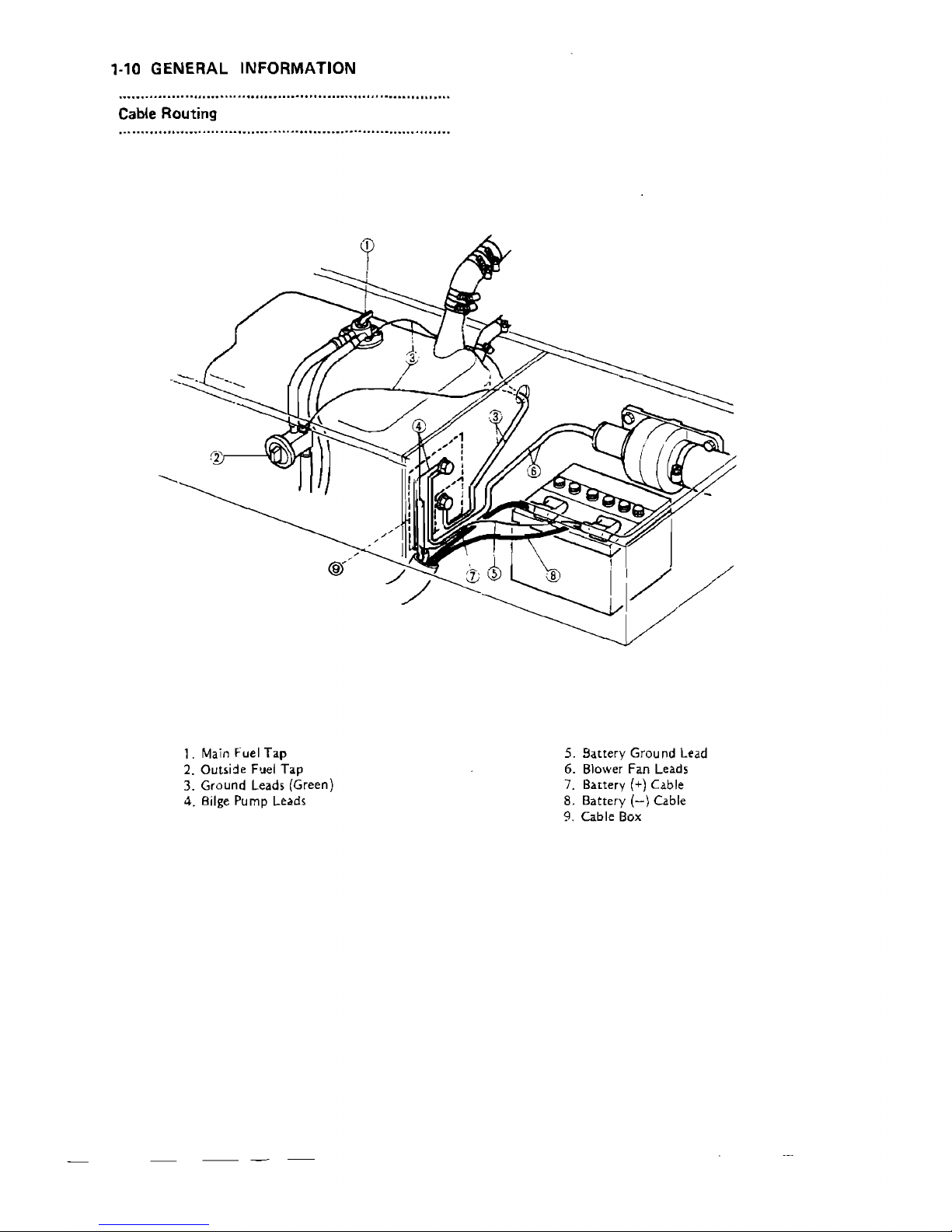
Cable Routing
1.
Main
Fuel Tap
5. Battery
Ground
Lead
2. Outside F'Jel Tap
6. Blower Fan Leads
3.
Ground
Leads (Green)
7. Battery
(+) Cable
4.
Bilge
Pump Leads
8. Battery
(-)
Cable
9. Cable Box
beerdart
termjna~.
GENERAL INFORMATION
1-11
o
To
Battery
(4-)
3
c¢======?®
7
Terminal
L
-
=='1----"'
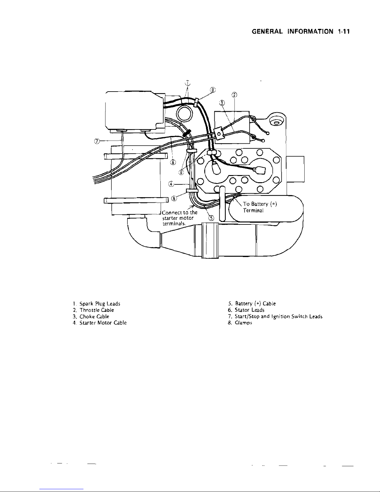
Connect
to
the
\-.
i
starter
m;;o~t=O.,'rlrT(;)"'nr:::==="if=:::7--~
1.
Spark
Plug Leads
5. Battery
(+)
Cable
2.
Throttle
Cable
6.
Stator
Leads
3.
Choke Cable
7.
Start/Stop and Ignition Switch Leads
4.
Starter
Motor Cable
8.
Clamps
beerdart
1-12
GENERAL INFORMATION
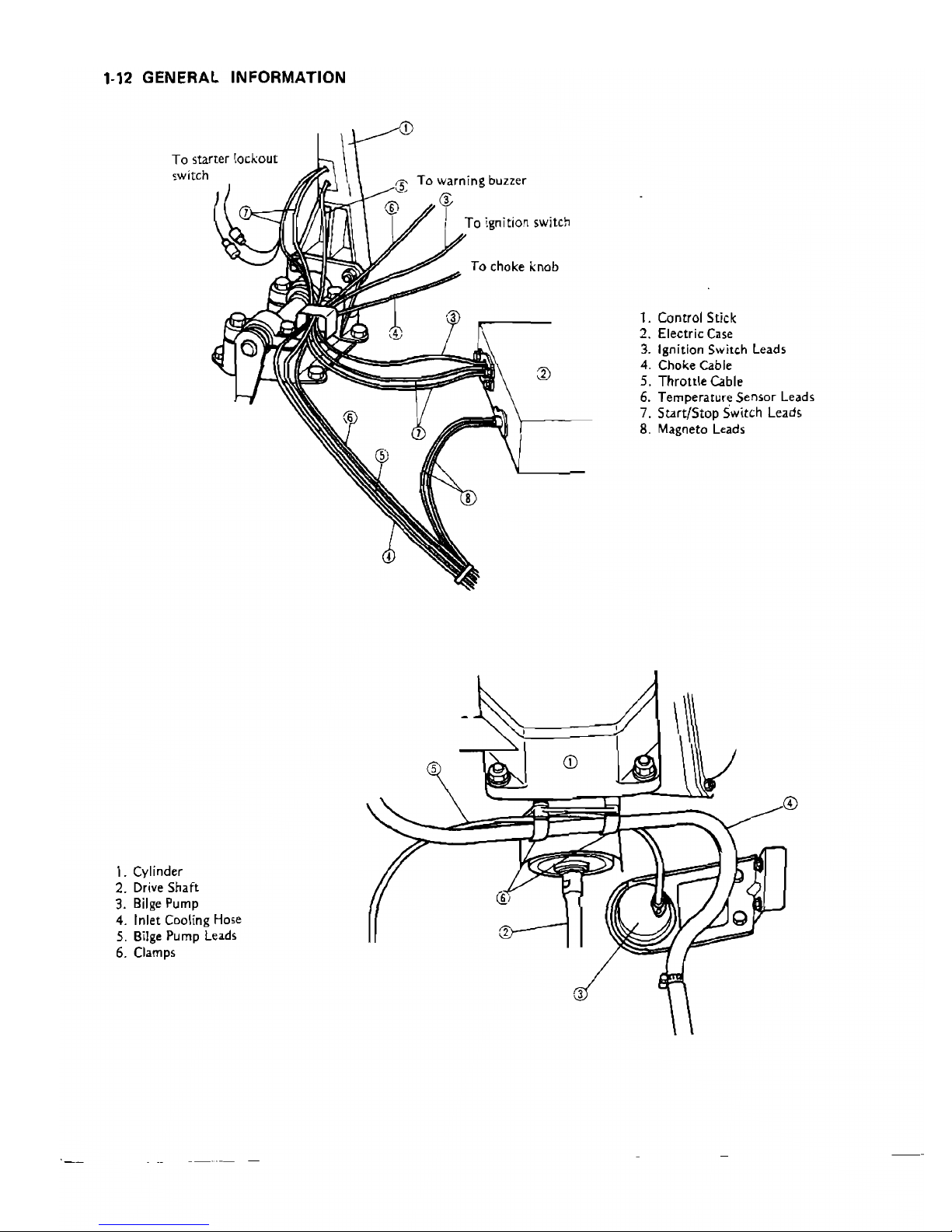
To starter I,ockout
switch
""
To warning buzzer
<1_
(j;
i
To
Ignition
switch
To choke knob
1. Control Stick
2. Electric
Case
3. Ignition Switch Leads
4. Choke Cable
5. Throttle Cable
6. Temperature Sensor Leads
7.
Start/Stop Switch Leads
8. Magneto Leads
5
1. Cylinder
2. Drive Shaft
3.
Bilge
Pump
4. Inlet Cooling Hose
2
5. Bilge Pump
leads
6. Clamps
3
beerdart
FUEL SYSTEM
2·'
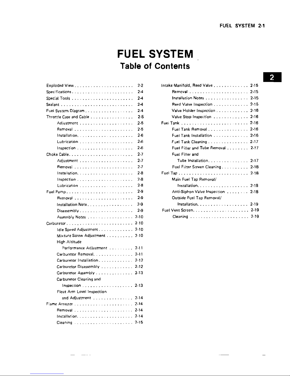
FUEL SYSTEM
Table
of
Contents
Exploded
View.
. . . . . . . .
2-2
Intake
Manifold, Reed Valve
..
, • , .
2-15
Choke Cable .
2·7
Fuel Filler
and
Inspection
.
2-8
Main Fuel
Tap
Removal/
Removal .
2-9
Outside
Fuel
Tap
Removal/
High
Altitude
Carburetor
Cleaning
and
Float Arm Level
Inspection
Specifications. . . . . . . .
2-4
Removal
......•
__
_ .
2-15
Special
Tools.
. . . , , 2-4
Installation Notes
•.•
, , .
2-15
Sealant
.
2-4
Reed Valve
Inspection
.
2-15
Fuel
System
Diagram .
2-4
Valve
Holder
Inspection _ .
._
2-16
Thronle
Case
and
Cable . 2-5
Valve
Stop
Inspection .
2-16
Adjustment
.
2-5
Fuel
Tank
_ . . . . . . . .
..
. .
2-16
Removal . 2-5
Fuel
Tank
Removal _
2-16
Installation..
. _ . 2-6
Fuel
Tank
Installation
_ .
2·16
Lubrication.
. . . .
2-6
Fuel
Tank
Cleaning.
. . .
2-17
Inspection .
2-6
Fuel Filler
and
Tube
Removal .
2-17
Adjustment
. 2-7
Tube
lmtallation
__
. _ _
2-17
Removal . 2-7
Fuel Filter Screen Cleaning _ .
2-18
Installation
..
, . 2-8
Fuel
Tap
_ . 2-
18
LUbrication.
. . . . . . . . . . . . 2-8
Installation_ _
..
_ _
2-18
Fuel
Pump.
. . .
..
. .
2-9
Anti-Siphon
Valve
Inspection
....•
2-18
Installation
Note .
2-9
Installation _ .
2-19
Disassembly .
2·9
Fuel
Vent
Screen
_ _ . ,
.•...
2-19
Assembly Notes . . . . . .
2-10
Cleaning _ . . _ _
2-19
Carburetor
.
2-10
Idle
Speed
Adjustment
.
2-10
Mixture
Screw
Adjustment
.
2-10
Performance
Adjustment
. 2-11
Carburemr
Removal. . 2-11
Carburetor
Installation
.
2-
12
Carburetor
Disassemb!y .
2-12
Carburetor
Assembly .
2-13
Impection
. 2-13
and
Adjustment
.
2-14
Flame
Arrester
.
2-14
Removal.
. . . . . . . . . .
..
. .
2-14
Install~tior1
.
2-14
Cleaning
2-15
beerdart
2-2 FUEL
SYSTEM
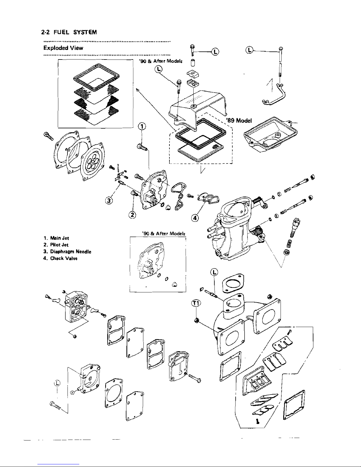
Exploded View
......................................................
-
................ I
©---~
~
~
,
,
,
,
,
,
,
, ,
!_---------------~
'90 & After
Models
,
.....
'90 & After
Models
I L
I
I
1.
Main
Jet
2. Pilot
Jet
3. Diaphragm Needle
4.
Check
Valve
I'/A
co,
)I~
i
Ih'
'~
beerdart
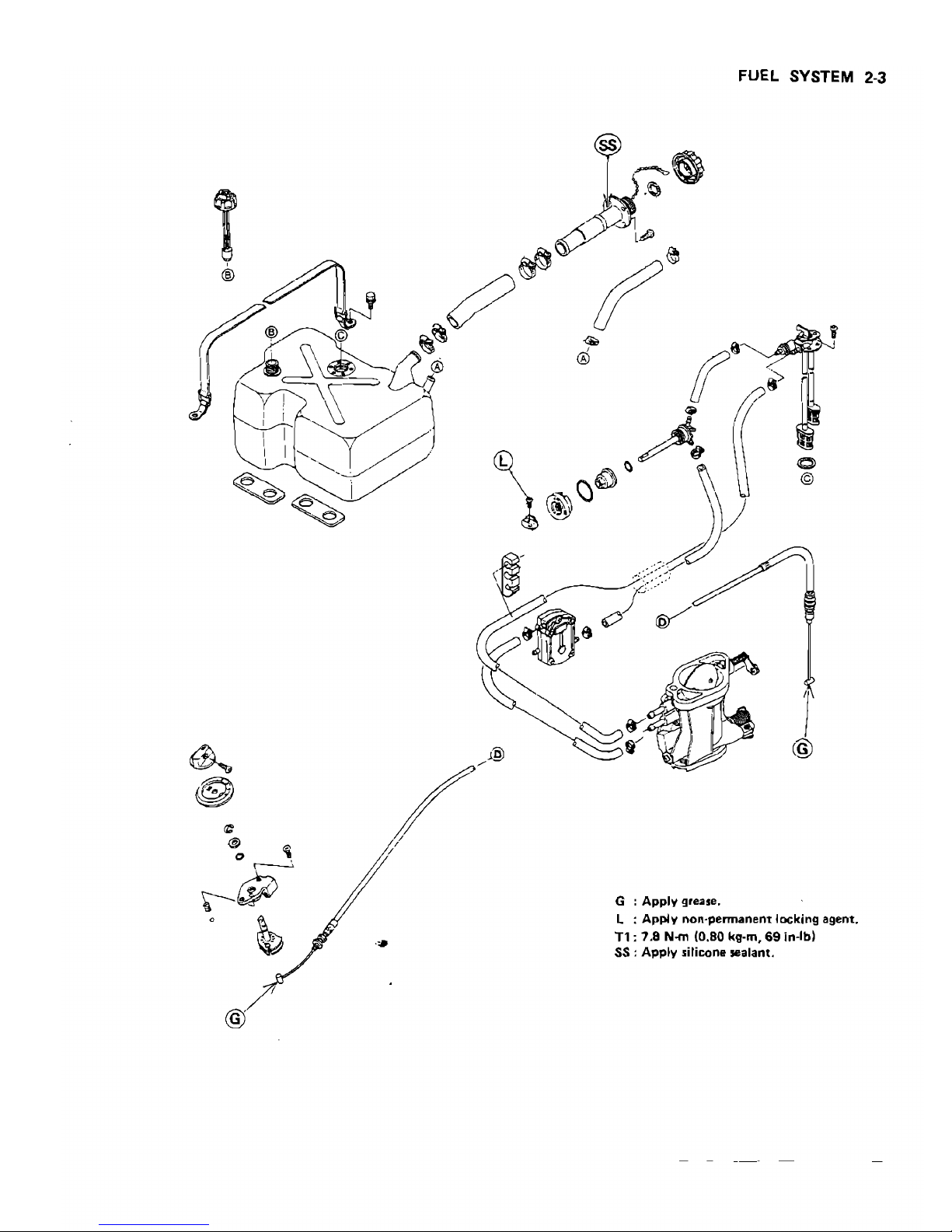
FUEL SYSTEM 2-3
/,
,
,
1
@
G
.
Apply grease. nt locking agent.
. ennane
L
.
Apply
non-p
69
in-Ibl
.
(080
kg-om,
78N-m
.
Tl:.
Tcone sealant.
SS : Apply SI I
@
7
beerdart
2-4 FUEL SYSTEM
.............................................................................
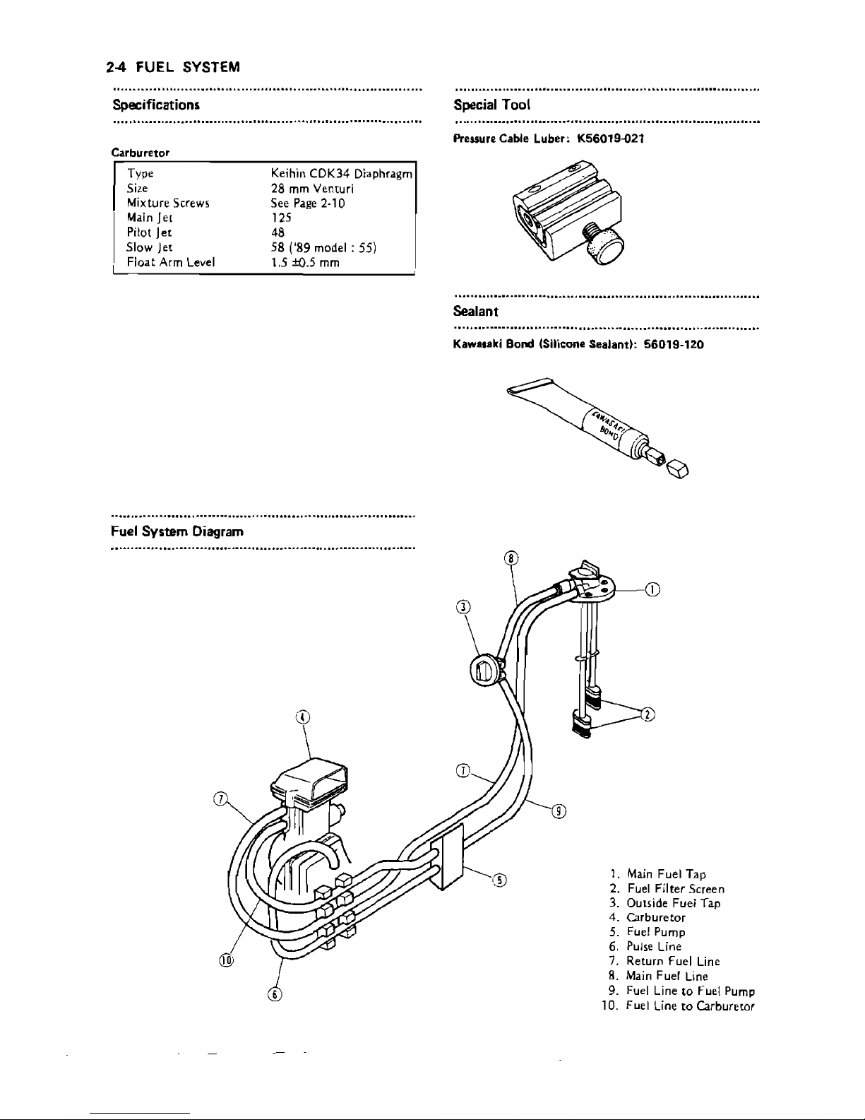
Specifications
.,
- , .
Carburetor
Type
5il:e
Mixture Screws
Main
Jet
Pilot
Jet
Slow Jet
Float
Arm
Level
Fuel
System
Diagram
Keihin CDK34 Diaphragm
28 mm Venturi
See
Page 2-10
125
48
58 ('89 model: 55)
1.5
±O.5
mm
W
Special Tool
Pressure Cable Luber: K56019-o21
Sealant
Kawasaki Bond (Silicone Sealant):
56019-120
:
CD
2
1.
Main
Fuel Tap
2.
Fuel
Filter Screen
3. Outside Fuel Tap
4.
Carburetor
5. Fuel Pump
6.
PUlse
Line
7. Return Fuel
Line
8.
Main
Fuel
Line
9.
Fuel
Line to Fuel
Pump
10. Fuel
Line
to
Carburetor
®
beerdart

Throttle Cable
Adjustment
eCheck throttle cable
~djustment.
OWith
the throttle lever relea5ed, the stop on the throt-
tle sh.aft lever should rest
.ag.ainst
the idle adjust screw,
and there should be slight slack
in
the throttle cable.
oWhen
the
throttle lever
is
fully applied (SQueezed), the
stop on
the
throttle shaft lever should be
all
the
w.ay
up .against the stop on the c.arburetor.
THROLLED CLOSED
THROTTLE
OPEN
(RELEASED) (APPLIED)
~
,
1.
Idle Adjust Screw
2.
Throttle Shaft Lever
3.
Stopper
elf
necessary, adjust the
throttle
cable.
eLoo5en and turn
the
locknuts at the br.acket until the
stop on the
throttle
pivot arm hits .against the idle
.adjust ,crew with slight cable slack.
eTighten
the
locknuts ,ecurely.
A.
LocknuH
qemoval
eDisconnect the
throttle
cable from the
urburetor.
A.
Throttle Cable
B.
Locknuts
FUEL
SYSTEM 2·5
,
eDis<l.'>semble
the control stick.
Pivot Boft
Steering Case
'&.
.
..
A.
Pivot Bolt
Covers
B.
Steering Case
A.
Covers
B.
Screws
beerdart
2-6
FUEL SYSTEM
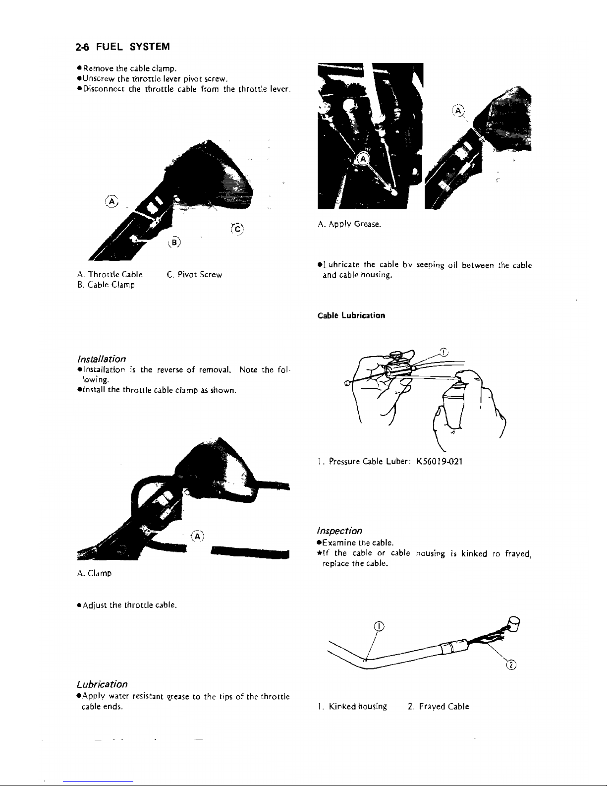
• Remove the cable clamp.
_Unscrew the
throttle
lever pivot screw.
-Disconnect the throttle cable
from
the thrott',e lever.
A.
Throttle
Cable
B.
Cable Clamp
C.
Pivot Screw
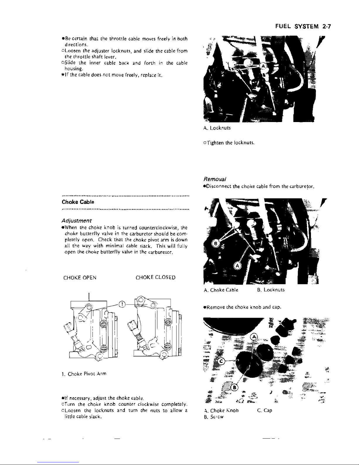
A.
Apply Grease.
eLubricate
the cable
bv
seeping oil
between
the cable
and
cable housing.
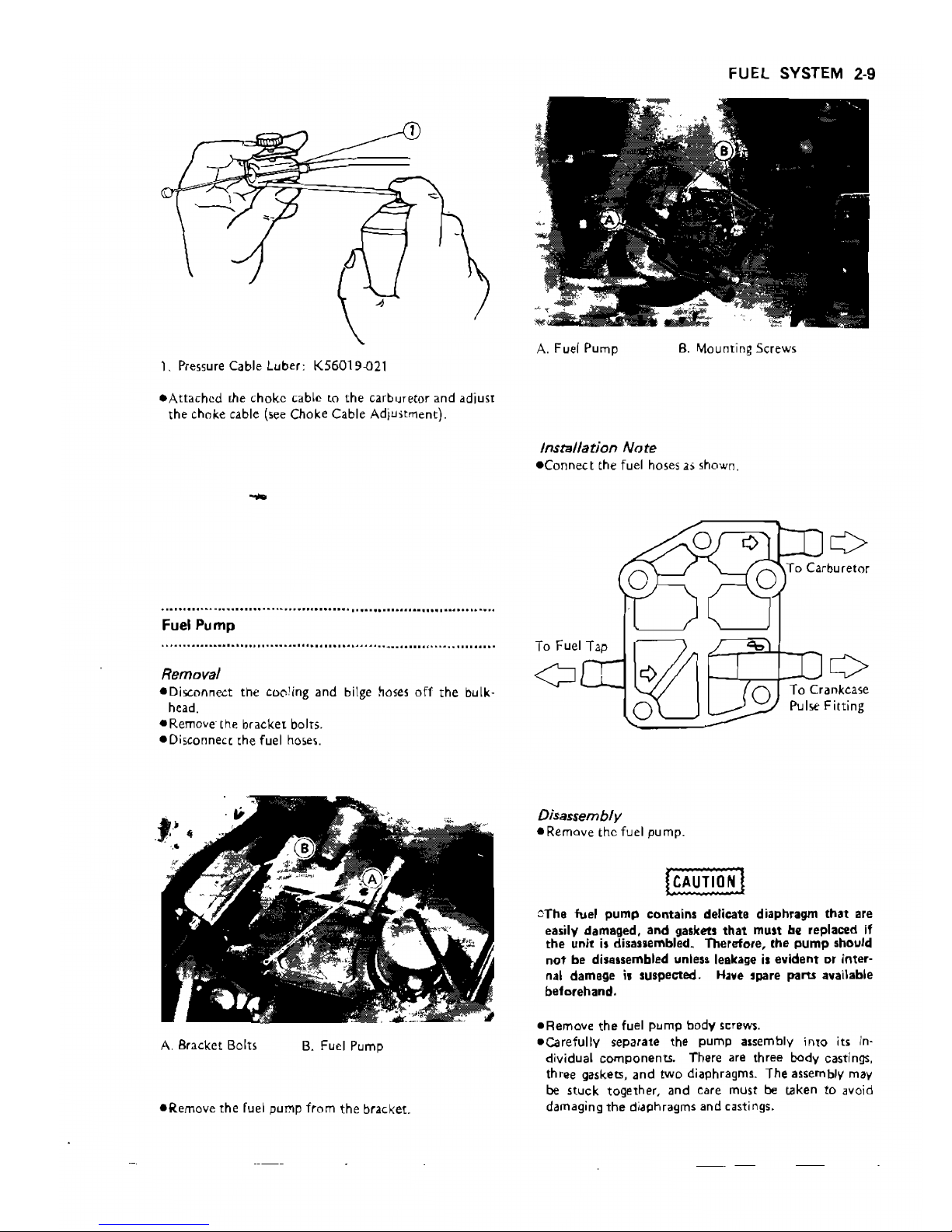
Cable lubrication
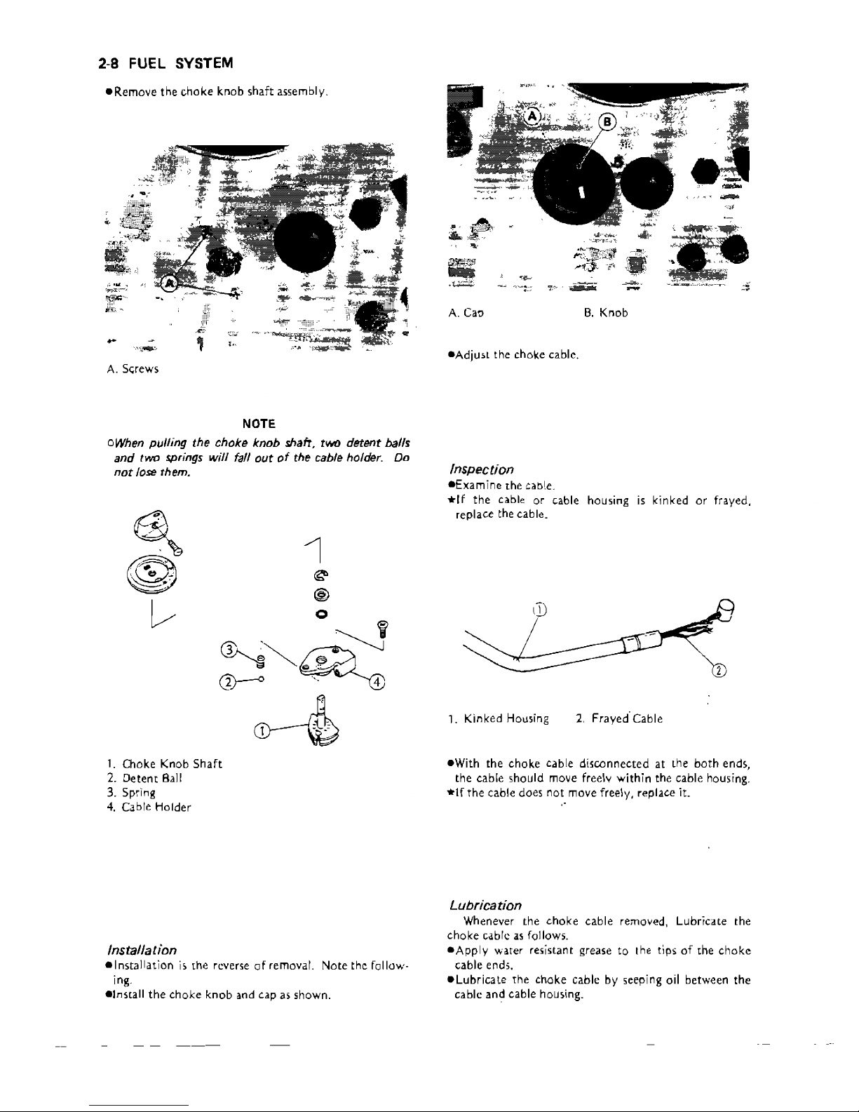
Installation
_Installation
is
the reverse
of
removal.
lowing.
elnstall
the
throttle
cable clamp
as
shown.
Note the fol-
1. Pressure Cable Luber: K56019-021
Inspection
eExamine
the cable.
*!f
the
cable
or
cable
replace
the
cable.
housing
is
kinked
fO
frayed,
A.
Clamp
_Adjust
the
throttle
C,lble.
~'
CD
,
Lubrication
eApply
water resistant grease to
the
tips
of
the
throttle
cable ends.
1.
Kinked housing 2.
FrJyed
Cable
beerdart
FUEL SYSTEM 2-7
_Be certain that the
throttle
cable moves freely in both
,
directions.
oLoo5en the adjuster locknuts, and slide the cable from
the
throttle
shaft lever.
oSlide
the
inner cable back and forth
in
the cable
housing.
*If
the cable does
not
move freely, replace it.
A.
Locknuts
oTighten
the locknuts.
Removal
eOi5connect
the
choke
cable from
thr
carbure!or.
Choke Cable
Adjustment
eWhen the choke knob
is
turned counterclockwise, the
choke butterfly valve
in
the carburetor should be com-
plelely open. Check
that
the choke piva[ arm
is
down
all the way with minimal cable slack. This will fully
open the
chokr
butterfly
valve
in
the carburetor.
CHOKE OPEN
CHOKE CLOSED
A. Choke Cable
B.
Locknuts
eRemove
the
choke
knob and cap.
/ '
~~~,J.
1.
Choke
Pi
VOL Arm
-If
necessary, adjust
the
chokr
cable.
cTurn
Lhe
choke knob counter clockwise completely.
cLoQsen the locknuts and turn
,he nuts
to
allow a
;.
Chokr
Knob
C.
Cap
little cable slack.
B.
Screw
beerdart
2-8
FUEL SYSTEM
eRemove
the
choke
knob
shaft
assembly.
A.
S<;rews
NOTE
oWhen pulling the choke knob shah, two detent balls
and
ryvo
springs
will
fall
out
of
the cable holder. Do
not
lose them.
1.
Choke Knob
Shaft
2.
Detem
Ball
3. Spring
4.
Cable
Holder
Installation
_Installation
is
[he reverse
of
removal.
Note
the
follow-
ing.
elnstall the choke knob
and
cap
as
shown.
A. Cat!
B.
Knob
.Adju~t
the
choke cable.
Inspection
-Examine
the
cabl.e.
*If
the
cable
or
cable housing
is
kinked
or
frayed,
replace the cable.
CD
1. Kinked Housing
2,
Frayed'Cable
_With
the
choke
cable
disconnected
at the
both
ends,
the
cable
should
move freely
within
the
cable housing.
*lfthe
cable does
not
move freely,
,eplace
it.
..
Lubrication
Whenever the
choke
cable removed, Lubricate the
choke
cdble
dS
follow:;.
-Apply
water resistant grease
to
the tips
of
the
choke
cable ends.
_Lubricate
the choke cable by seeping oil between the
cable and cable housing.
1
beerdart
FUEL SYSTEM
2-9
A.
Fuel Pump
B.
Mounting Screws
1. Pressure Cable Luber: K56019-021
_Attached the choke cable to the carburetor and adju,t
the choke cable (see Choke Cable Adjustment).
-
Fuel Pump
Removal
_Disconnect the c00'ing and bilge hoses
off
the
bulk-
head.
_Remove- the bracket bolts.
_Disconnect the fuel
hose~.
A.
Bracket Bolts
B.
Fuel Pump
_Remove
the
fuel pump from
the
bracket.
Installation
Note
_Connect
the fuel hoses
as
shown.
Disassembly
_ Remove the fuel pump.
0The fuel
pump
contains delicate diaphragm
that
are
easily damaged,
and
gaskets
that
must be
replaad
jf
the
unit
is
disassembled. Therefore, the
pump
should
not
be disassembled unless leakage
is
evident or inter-
nal damege
;,
suspected.
Have
spare
parts
available
beforehand.
_Remove
the
fuel pump body screm.
_carefully separate the pump assembly into its
in-
dividual COlTlponents. There are three body castings,
three gaskets,
and
two
diaphragms. The assembly may
be
stuck together, and care must
be
taken
to
,woid
damaging
the
diaphragms and castings.
beerdart
2·10 FUEL SYSTEM
Idle Speed
,'J'\
"""
1,250 ±100
rpm
(in
water)
1,800
tl00
rpm
(out
of
water)
1
,);
Q 6
,'- " "
~
" ,
, .
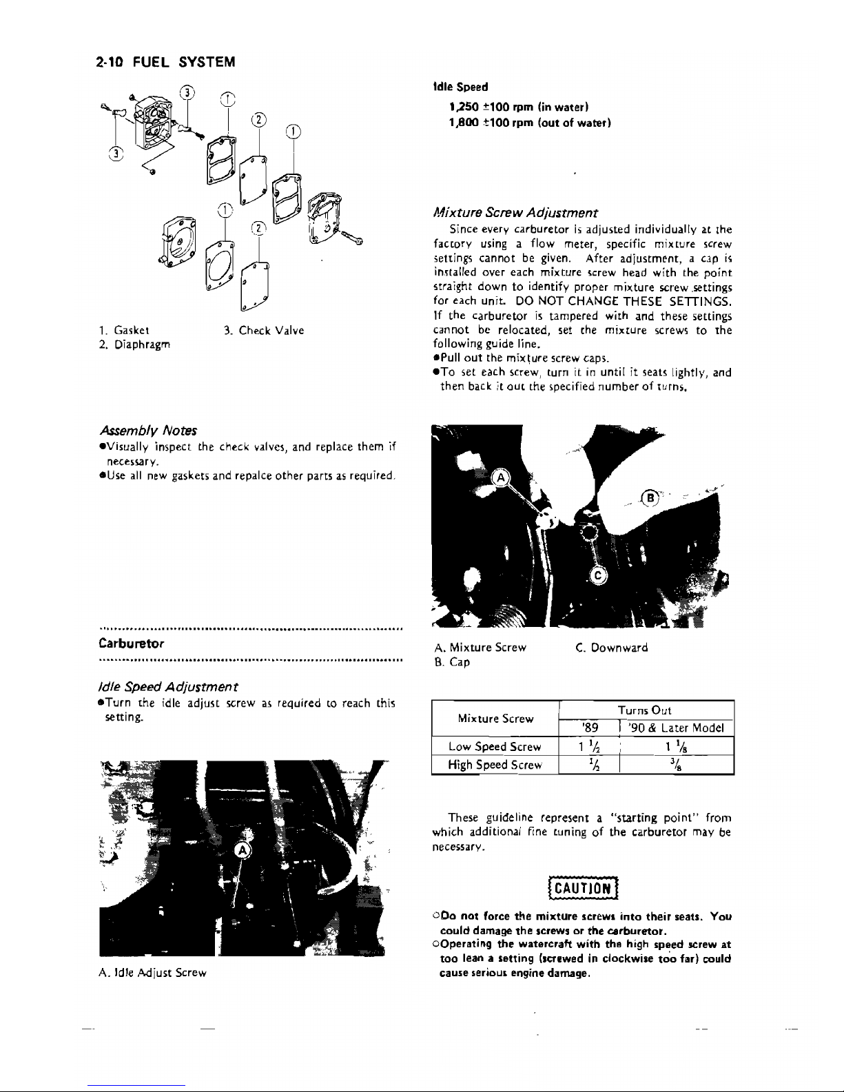
1. Gasket 3. Check Valve
2.
Diaphragm
Assembly Notes
.Visually
inspect the check valves, and replace them
if
necessary.
_Use
all
new gaskets
and
repalce
other
parts
as
required.
.............
" - .
Carburetor
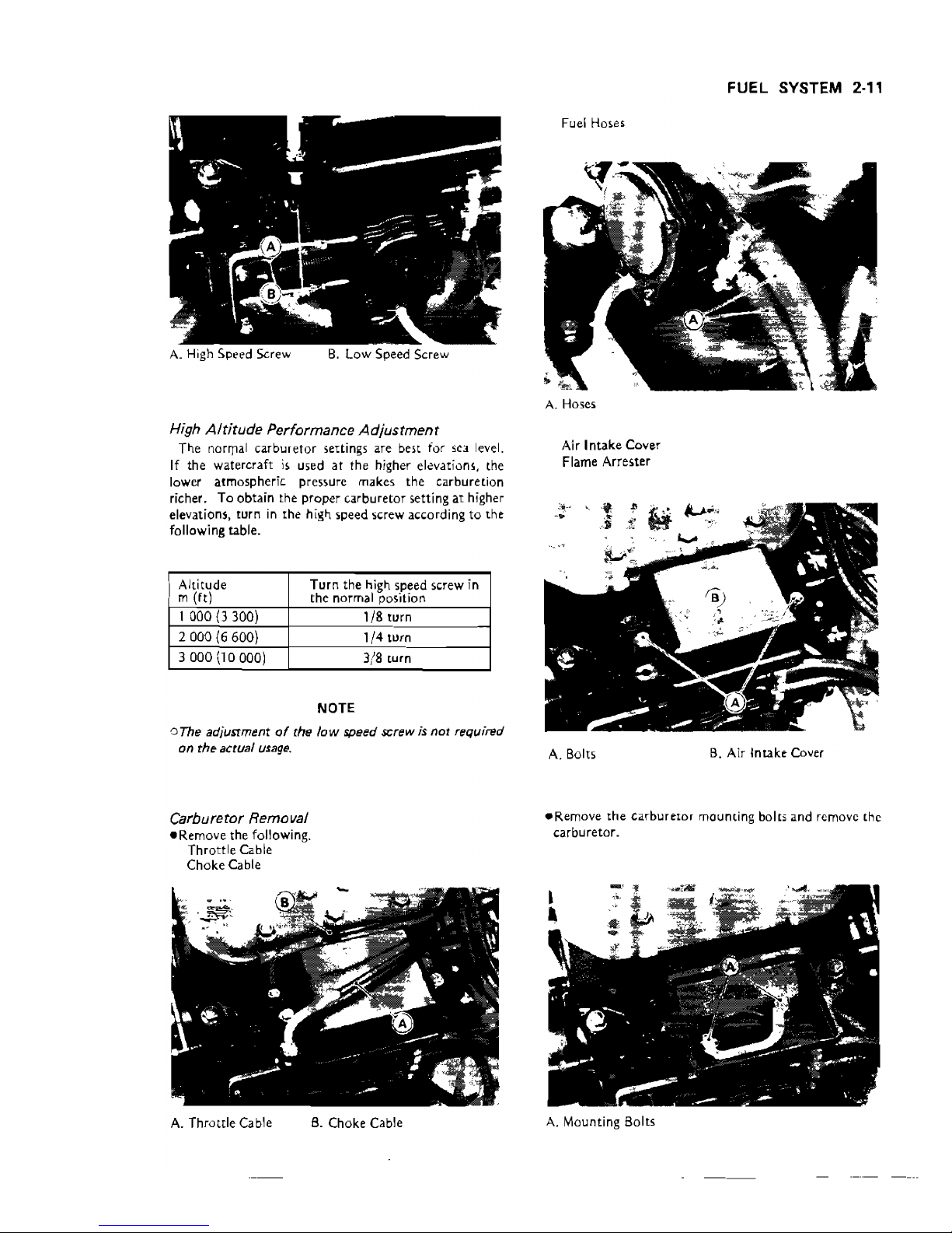
Idle
Speed
Adjustment
_Turn
the idle
adjust
screw
as
required to reach this
~tting.
A. Idle A.djust Screw
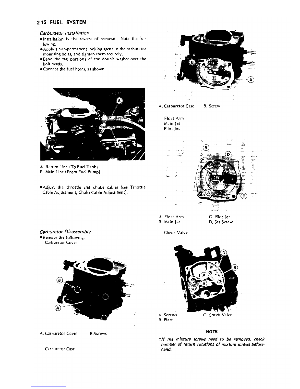
Mixture Screw
Adjustment
Since every
carburetor
i'i adjusted individually at
the
hcrory
using a flow meter, specific mixture screw
;;ettings
cannot
be given. After adjustment, a cap
is
imtalled over each
mixture
screw head
with
the
point
straight
down
to
identify proper mixture
~rew
,~ttings
for each unit. DO NOT CHANGE THESE SETTINGS.
If
the
carburetor
is
tampered with and these settings
cannot
be relocated, set the mixtUre screws
to
the
following guide line.
ePull
out
the mix\ure screw caps.
eTo
set each screw, turn it
in
until it seats lightly, and
then
back it oUt the specified
number
of
turns.
A. Mixture Screw
B.
Cap
C.
Downward
Mixture Screw
Turn~
Out
'89
1 Ih
'h
I
'90
& Later Model
,
1 I/
S
I
'I,
Low Speed Screw
High Speed Screw
These guideline represent a
"starting
point"
from
which additional fine tuning
of
the
carburetor
may
be
necessary.
(i:AUT(O~]
000
not
force
the
mixture screw.
into
their seats. You
could damage
the
screws
or
the
carburetor.
oOperating
the
watercraft
with
the high speed screw
at
too
lean a setting (screwed in clockwise
too
far) could
cause serious engine damage.
beerdart
FUEL SYSTEM 2·"
A.
High
Spl.'l.'d
Screw 8.
low
Speed Screw
H;gh
Alt;tude Performance
Adjustment
The norl]lal carburetor sellings are best for sea level.
If the watercraft
is
used
at
the higher elevatiom, the
lower atmospheric pressure makes the carburetion
richer. To obtain the proper carburetor setting
aT
higher
elevations, turn
in
the high speed screw according
to
the
following table.
Altitude
m
(ft)
Turn the high speed screw
in
the normal position
1 000 (J 300)
1/8
turn
2 000
(6
600)
1/4
turn
3 000 (l 0
ODD)
3/8 turn
Fuel Hoses
A. Hoses
Air Intake Cover
Flame Arrester
NOTE
oThe adjustment
of
the low speed screw;s not required
on the actual
usage.
A.
Bolts
B.
Air Intake Cover
Carburetor Removal
eRemove
the
carburetor mounting bolts and remove the
eRemove
the following.
carburetor.
Throttle Cable
Choke Cable
A.
Throttle Cable
B.
Choke Cable
A.
Mounting Bolts
beerdart
2·12 FUEL
SYSTEM
Carburetor Installation
elnstallation
is
the
reverse
of
removal. Note the fol-
lowing.
-Apply
a nan-permanent locking agent to
the
carburetor
mounting bolts,
and
tighten them securely.
eBend
the
tab
portions
of
the
double
washer over the
bolt
heads.
_Connect
the
fuel hoses, as shown,
A. Return Line (To Fuel
Tank)
B.
Main Line
(From
Fuel Pump)
-Adjust
the
throttle
and choke cables (see Trhottle
Cable Adjustment, Choke Cable Adjustment).
Carburetor Disassembly
_Remove the following.
Carburetor Cover
A.
Carburetor Cover
a.Screws
Carbureror Case
A.
Carburetor
Case
g.
Screw
Float
Arm
Main
Jet
Pilot
Jet
A.
Float
Arm
C.
Pilot
let
B.
Main
Jet
D.
Sel
Screw
Check
Valve
A.
Screws
C. Check Valve
B.
Plate
NOTE
olf
the
mixture
screws need to be removed, check
number
of
return rotations
of
mixture
screWS'
before-
hand.
beerdart
 Loading...