

ER-6n
ER-6n ABS
Motorcycle
Service Manual

Quick Reference Guide
j
j
j
j
j
j
j
j
j
j
j
j
j
j
j
j
j
General Information 1
Periodic Maintenance 2
Fuel System (DFI) 3
Cooling System 4
Engine Top End 5
Clutch 6
Engine Lubrication System 7
Engine Removal/Installation 8
This quick reference guide will assist
you in locating a desired topic or procedure.
•Bend the pages back to match the
black tab of the desired chapter number with the black tab on the edge at
each table of contents page.
•Refertothe sectionaltable ofcontents
for the exact pages to locate the specific topic required.
Crankshaft/Transmission 9
Wheels/Tires 10
Final Drive 11
Brakes 12
Suspension 13
Steering 14
Frame 15
Electrical System 16
Appendix 17


ER-6n
ER-6n ABS
Motorcycle
Service Manual
All rights reserved. No parts of this publication may be reproduced, stored in a retrieval system, or
transmitted in any form or by any means, electronic mechanical photocopying, recording or otherwise,
without the prior written permission of Quality Assurance
Company/Kawasaki Heavy Industries, Ltd., Japan.
No liability can be accepted for any inaccuracies or omissions in this publication, although every possible
care has been taken to make it as complete and accurate as po
The right is reserved to make changes at any time without prior notice and without incurring an obligation
to make such changes to products manufactured previously. See your Motorcycle dealer for the latest
information on product improvements incorporated afte
All information contained in this publication is based on the latest product information available at the time
of publication. Illustrations and photographs in this publication are intended for reference use only and may
not depict actual model component parts.
r this publication.
Division/Consumer Products & Machinery
ssible.
© 2008 Kawasaki Heavy Industries, Ltd. First Edition (1) : Nov. 10, 2008 (M)
LIST OF ABBREVIATIONS
A ampere(s) lb pound(s)
ABDC after bottom dead center m meter(s)
AC alternating current min minute(s)
ATDC after top dead center N newton(s)
BBDC before bottom dead center Pa pascal(s)
BDC bottom dead center PS horsepower
BTDC before top dead center psi pound(s) per square inch
°C degree(s) Celsius r revolution
DC direct current rpm revolution(s) per minute
F farad(s) TDC top dead center
°F degree(s) Fahrenheit TIR total indicator reading
ft foot, feet V volt(s)
g gram(s) W watt(s)
h hour(s) Ω ohm(s)
L liter(s)
COUNTRY AND AREA CODES
AT Austria GB United Kingdom
AU Australia MY Malaysia
BR Brazil SEA South East Asia
CA Canada TH Thailand
CAL California US United States
CH Switzerland WVTA (FULL H) WVTA Model with Honeycomb Catalytic
Converter (Full Power)
DE Germany GB WVTA
(FULL H)
EUR Europe
WVTA Model with Honeycomb Catalytic
Converter (Left Side Traffic, Full Power)

EMISSION CONTROL INFORMATION
To protect the environment in which we all live, Kawasaki has incorporated crankcase emission (1) and exhaust emission (2) control systems in compliance with applicable regulations of
the United States Environmental Protection Agency and California Air Resources Board. Additionally, Kawasaki has incorporated an evaporative emission control system (3) in compliance
with applicable regulations of the California Air Resources Board on vehicles sold in California
only.
1. Crankcase Emission Control System
Thissystemeliminatesthe releaseof crankcasevapors intothe atmosphere. Instead, thevapors
are routed through an oil separator to the inlet side of the engine. While t he engine is operating,
the vapors are drawn into combustion chamber, where they are burned along with the fuel and air
supplied by the fuel injection system.
2. Exhaust Emission Control System
This system reduces the amount of pollutants discharged into the atmosphere by the exhaust
of this motorcycle. The fuel, ignition, and exhaust systems of this motorcycle have been carefully
designed and constructed to ensure an efficient engine with low exhaust pollutant levels.
The exhaust system of this model motorcycle manufactured primarily for sale in California in-
cludes a catalytic converter system.
3. Evaporative Emission Control System
Vapors caused by fuel evaporation in the fuel system are not vented into the atmosphere. In-
stead, fuel vapors are routed into the r unning engine to be burned, or stored in a canister when
the engine is stopped. Liquid fuel is caught by a vapor separator and returned to the fuel tank.
The Clean Air Act, which is the Federal law covering motor vehicle pollution, contains what is
commonly referred to as the Act’s “tampering provisions”.
“Sec. 203(a) The following acts and the causing thereof are prohibited.
(3)(A) for any person to remove or r ender inoperative any device or element of design installed
on or in a motor vehicle or motor vehicle engine in compliance with regulations under this
titleprior to its sale anddelivery to the ultimatepurchaser,or for any manufacturer ordealer
knowingly to remove or render inoperativeany such device or element of design after such
sale and delivery to the ultimate purchaser.
(3)(B) for any person engaged in the business of repairing, servicing, selling, leasing, or trading
motor vehicles or m otor vehicle engines, or who operates a fleet of motor vehicles knowingly to remove or render inoperative any device or element of design installed on or in a
motor vehicle or motor vehicle engine in compliance with regulations under this title following its sale and delivery to the ultimate purchaser...”
NOTE
The phrase “remove or render inoperative any device or element of design” has been generally
○
interpreted as follows.
1. Tampering does not include the temporary removal or rendering inoperative of devices or elements of design in order to perform maintenance.
2. Tampering could include.
a.Maladjustment of vehicle components such that the emission standards are ex-
ceeded.
b.Use of replacement parts or accessories which adversely affect the performance
or durability of the motorcycle.
c.Additionof componentsoraccessories thatresult inthevehicle exceedingthe stan-
dards.
d.Permanently removing, disconnecting, or rendering inoperative any component or
element of design of the emission control systems.
WE RECOMMEND THAT ALL DEALERS OBSERVE THESE PROVISIONS OF FEDERAL
LAW,THE VIOLATION OF WHICH ISPUNISHABLE BY CIVIL PENALTIESNOT EXCEEDING
$10 000 PER VIOLATION.

TAMPERING WITH NOISE CONTROL SYSTEM PROHIBITED
Federal law prohibits the following acts or the causing thereof. (1) The removal or rendering
inoperativeby any personotherthan forpurposes of maintenance,repair, orreplacement, of any
device or element of design incorporated into any new vehicle for the purpose of noise control
prior to i ts sale or delivery to the ultimate purchaser or while it is in use, or (2) the use of the
vehicle after such device or element of design has been removed or rendered inoperative by
any person.
Among those acts presumed to constitute tampering are the acts listed below.
Replacement of the original exhaust system or muffler with a component not in compliance
•
with Federal regulations.
Removal of the muffler(s) or any internal portion of the muffler(s).
•
Removal of the air box or air box cover.
•
Modifications to the muffler(s) or air inlet system by cutting, drilling, or other means if such
•
modifications result in increased noise levels.
Foreword
This manual is designed primarily for use by
trained mechanicsin a properly equippedshop.
However,it containsenough detailand basicinformationto makeituseful tothe ownerwho desiresto performhis own basicmaintenance and
repair work. A basic knowledge of mechanics,
the proper use of tools, and workshop procedures must be understood in order to carry out
maintenance and repair satisfactorily. Whenever the owner has insufficient experience or
doubts his ability to do the work, all adjustments, maintenance, and repair should be carried out only by qualified mechanics.
In order to perform the work efficiently and
to avoid costly mistakes, read the text, thoroughly familiarize yourself with the procedures
beforestarting work, andthen dothe work ca
fully in a clean area. Whenever special tools or
equipment are specified, do not use makeshift
tools or equipment. Precision measurem
can only be made if the proper instruments are
used, and the use of substitute tools may adversely affect safe operation.
For the duration of the warranty period,
we recommend that all repairs and scheduled
maintenance be performed in
thisservice manual. Any ownermaintenance or
repair procedure not performed in accordance
with this manual may void
To get the longest life out of your vehicle.
Follow the Periodic M aintenance Chart in the
•
Service Manual.
Be alert for problems and non-scheduled
•
maintenance.
Use proper tools and
•
torcycle parts. Special tools, gauges, and
testers that are necessary when servicing
Kawasaki moto
Service Manual. Genuine parts provided as
spare parts are listed in the Parts Catalog.
Follow the p
•
fully. Don’t take shortcuts.
Rememberto keepcomplete recordsofmain-
•
tenance a
parts installed.
rcycles are introduced by the
rocedures in this manual care-
nd repair with dates and any new
genuine Kawasaki Mo-
accordance with
the warranty.
re-
ents
How to Use This Manual
In this manual, the product is divided into
its major systems and these systems make up
the manual’s chapters. The Quick Reference
Guide shows you all of the product’s system
and assists in locating their chapters. Each
chapter in turn has its own comprehensive Table of Contents.
For example, if you want ignition coil information, use the Quick Reference Guide to locate
the Electrical System chapter. Then, use the
Table of Contents on the first page of the chapter to find the Ignition Coil section.
Whenever you see these WARNING and
CAUTION symbols, heed their instructions!
Always follow safe operating and maintenance
practices.
WARNING
This warning symbol identifies special
instructions or procedures which, if not
correctly followed, could result in per-
sonal injury, or loss of life.
CAUTION
This caution symbol identifies special
instructions or procedures which, if not
strictly observed, could result in dam-
age to or destruction of equipment.
This manual contains four more symbols (in
additionto WARNINGand CAUTION)whi
help you distinguish different types of information.
NOTE
This note symbol indicates points of par-
○
ticular interest for more efficient and con-
venient operation.
Indicates a procedural step or work to be
•
done.
Indicates a procedural sub-step or how to do
○
the work of the procedural step it follows. It
also precedes the te
Indicates a conditional step or w hat action to
takebased on theresultsofthe testor inspec-
tion in the proced
lows.
In most chaptersan exploded view illustration
of the system com
Contents. In these illustrations you will find the
instructionsindicating which partsrequire specified tighten
agent during assembly.
ing torque, oil, grease or a locking
xt of a NOTE.
ural step or sub-step it fol-
ponents follows the Table of
chwill


GENERAL INFORMATION 1-1
General Information
Table of Contents
Before Servicing ..................................................................................................................... 1-2
Model Identification................................................................................................................. 1-7
General Specifications............................................................................................................ 1-10
Unit Conversion Table ............................................................................................................ 1-13
1
1-2 GENERAL INFORMATION
Before Servicing
Before starting to perform an inspection service or carry out a disassembly and reassembly operation on a m otorcycle, read the precautions given below. To facilitate actual operations, notes, illustrations, photographs, cautions, and detailed descriptions have been included in each chapter wherever
necessary. This section explains the items that require particular attention during the removal and
reinstallation or disassembly and reassembly of general parts.
Especially note the following:
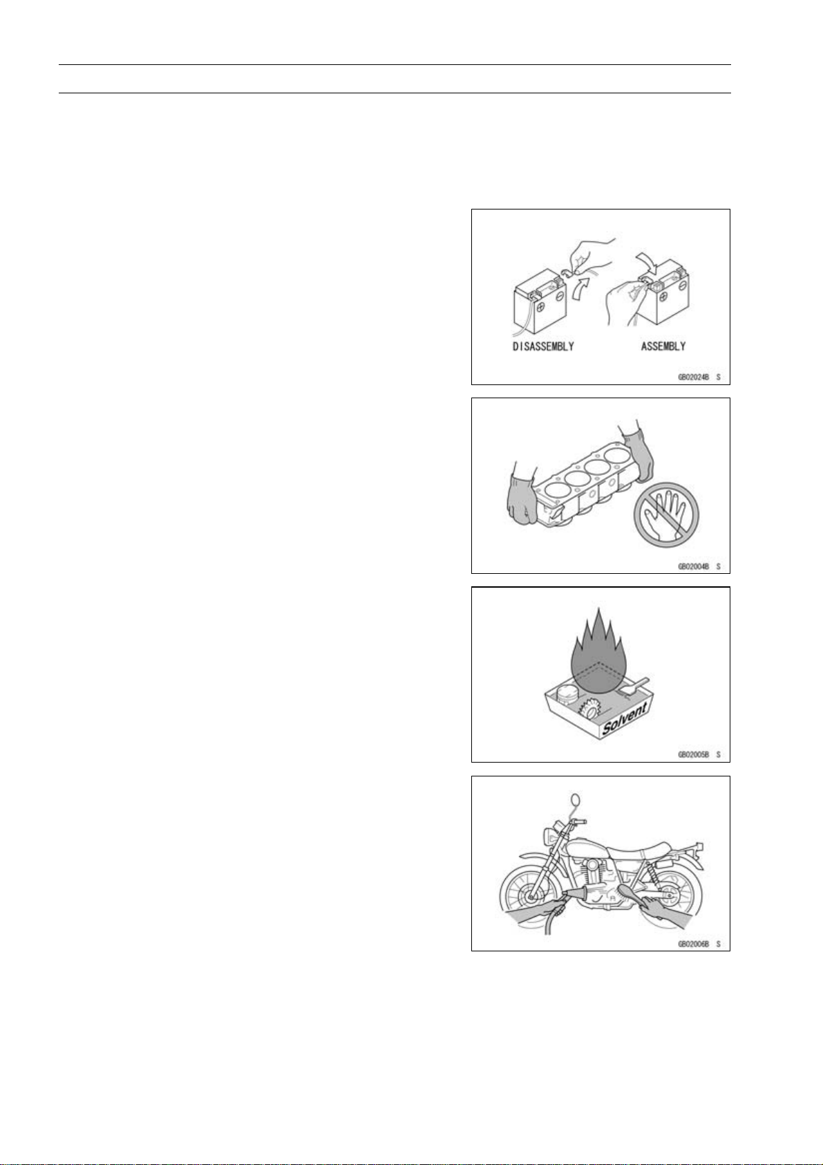
Battery Ground
Before completingany service on the motorcycle,disconnect the battery cables from the battery to prevent the engine from accidentally turning over. Disconnect the ground
cable (–) first and then the positive (+). When completed
with the service, first connect the positive (+) cable to the
positive (+) terminal of the battery then the negative (–) cable to the negative terminal.
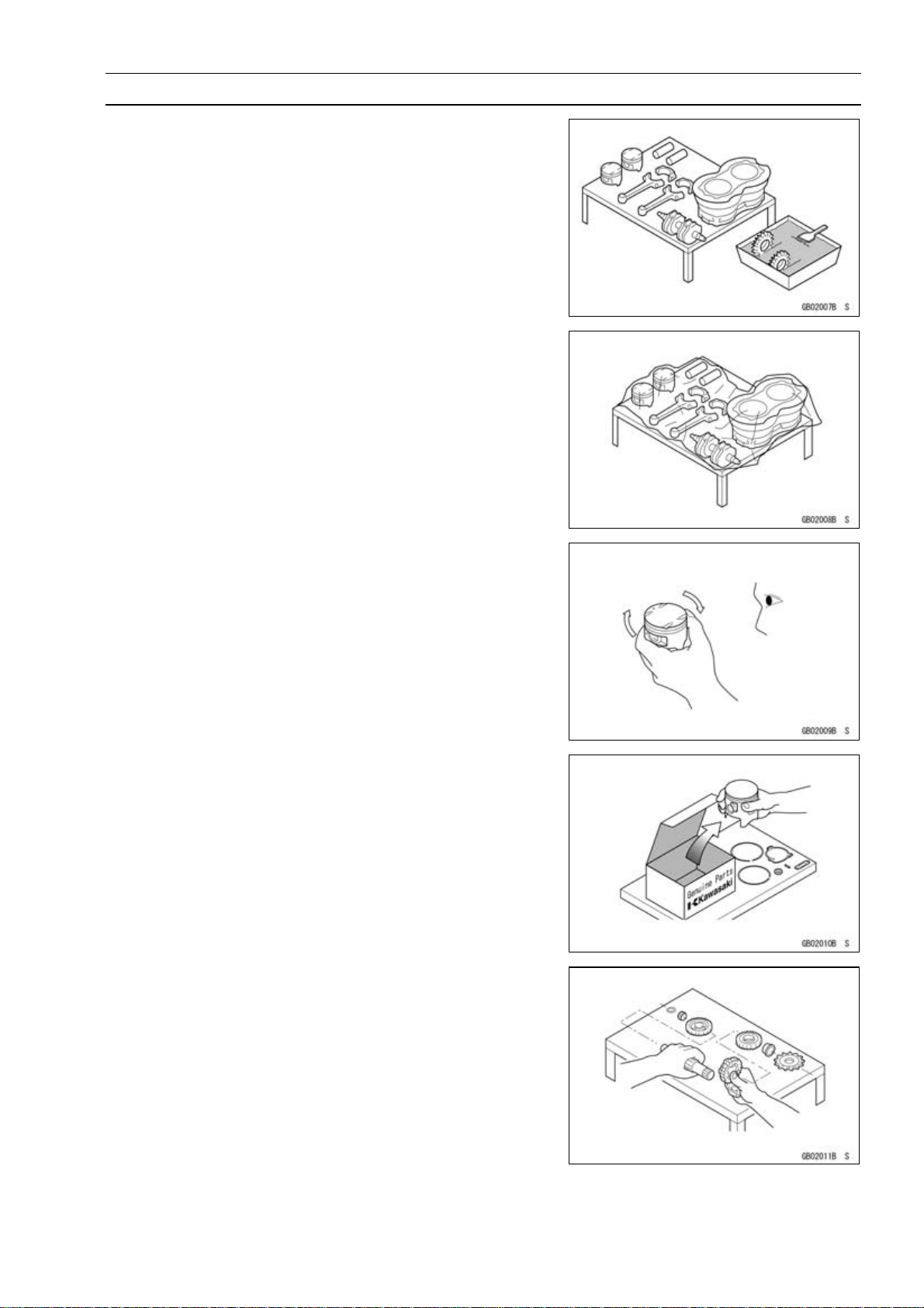
Edges of Parts
Lift large or heavy parts wearing gloves to prevent injury
from possible sharp edges on the parts.
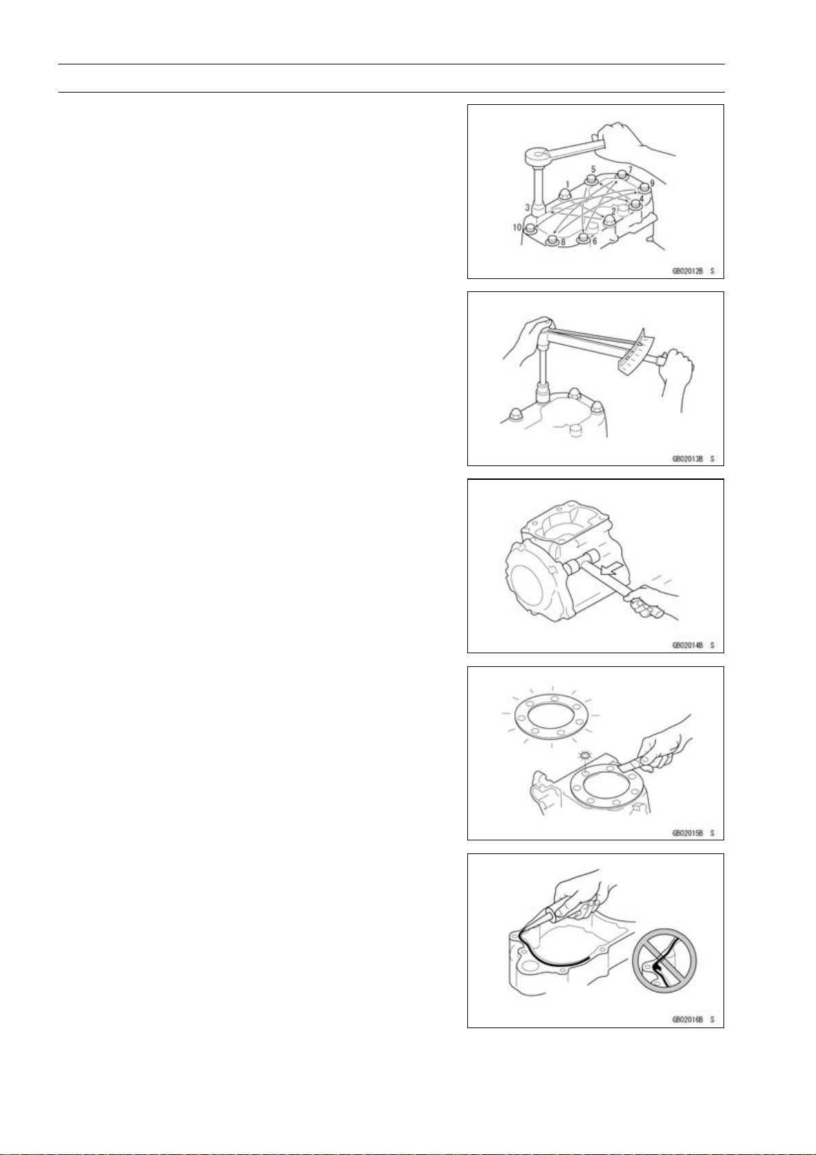
Solvent
Use a high-flash point so
-flash point solvent should be used according to directions
of the solvent manufacturer.
lvent when cleaning parts. High
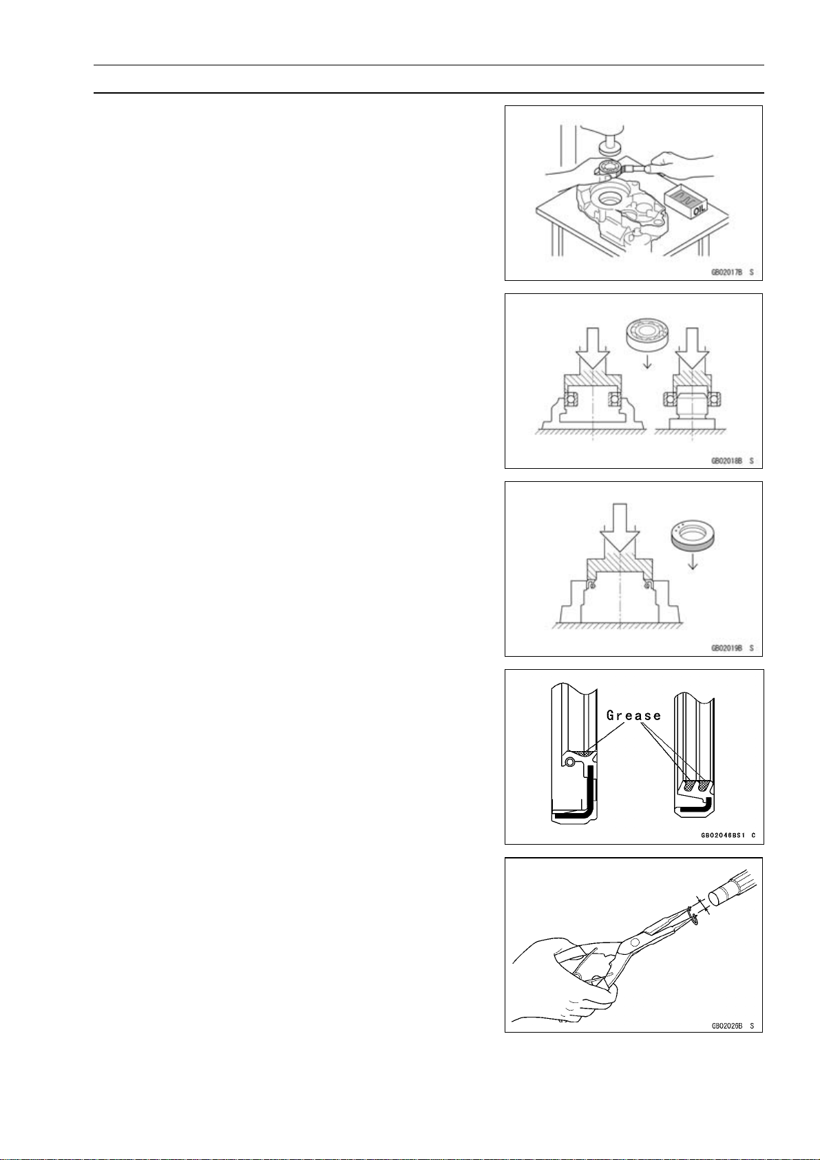
Cleaning Vehicle before Disassembly
Clean the vehicle thoroughly before disassembly. Dirt or
otherforeign materialsentering intosealed areasduring vehicle disassembly can cause excessivewear and decrease
performance of the vehicle.
Before Servicing
Arrangement and Cleaning o f Removed Parts
Disassembled parts are easy to confuse. Arrange the
parts according to the order the parts were disassembled
and clean the parts in order prior to assembly.
Storage of Removed Parts
After all theparts including subassembly parts have been
cleaned, store the parts in a clean area. Put a clean cloth
or plastic sheet over the parts to protect from any foreign
materials that may collect before re-assembly.
GENERAL INFORMATION 1-3
Inspection
Reuse of worn or damaged parts may lead to serious accident. Visually inspectremoved parts for corrosion, discoloration, or other damage. Refer to the appropriate sections
of thismanual for servicelimits on individualparts. Replace
the parts if any damage has been found or if the part is beyond its service limit.
Replacement Parts
Replacement parts must be KAWASAKI genuine or
recommended by KAWASAKI. Gaskets, O-rings, oil seals,
grease seals, circlips or cotter pins must be replaced with
new ones whenever disassembled.
Assembly Order
In mostcases assembly order isthereverse of disassembly, however, if assembly order is provided in this Service
Manual, follow the procedures given.
1-4 GENERAL INFORMATION
Before Servicing
Tightening Sequence
Generally, when installing a part with several bolts, nuts,
or screws, start them all in their holes and tighten them to
a snug fit. Then tighten them according to the specified sequence to prevent case warpage or deformation which can
lead to m alfunction. Conversely when loosening the bolts,
nuts, or screws, first loosen all of them by about a quarter turn and then remove them. If the specified t ightening
sequence is not indicated, tighten the fasteners alternating
diagonally.
Tightening Torque
Incorrect torque applied to a bolt, nut, or screw may
lead to serious damage. Tighten fasteners to the specified
torque using a good quality torque wrench. Often, the
tightening sequence is followed twice-initial tightening and
final tightening with torque wrench.
Force
Use common sense during disas
excessiveforce can causeexpensive or hardto repair damage. When necessary, remove screws that have a non
-permanent locking agent
Use a plastic-faced mallet whenever tapping is necessary.
applied using an impact driver.
sembly and assembly,
Gasket, O-ring
Hardening, shrinkage, or damage of both gaskets
and O-rings after disassembly can reduce sealing performance. Remove old gaskets and clean the sealing
surfaces thoroughly so that no gasket material or other
material remains. Install new gaskets and replace used
O-rings when re-assembling
Liquid Gasket, Non-permanent Locking Agent
For applications that require Liquid Gasket or a
Non-permanent Locking Agent, clean the surfaces so
that no oil residue remains before applying liquid gasket or
non-permanent locking agent. Do not apply them excessively. Excessive application can clog oil passages and
cause serious damage.
Before Servicing
Press
For items such as bearings or oil seals that must be
pressed into place, apply small amount of oil to the contact area. Be sure to maintain proper alignment and use
smooth movements when installing.
Ball Bearing and Needle Bearing
Do not remove pressed ball or needle unless removal is
absolutely necessary. Replace with new ones whenever
removed. Press bearings with the manufacturer and size
marks facing out. Press the bearing into place by putting
pressure on the correct bearing race as shown.
Pressing the incorrect race can cause pressure between
the inner and outer race and result in bearing damage.
GENERAL INFORMATION 1-5
Oil Seal, Grease Seal
Donot removepressed oilorgreasesealsunless removal
is necessary. Replace with new ones whenever removed.
Pressnewoil seals withmanufacture and sizemarks facing
out. Make sure the seal is aligned properly when installing.
Apply specified grease to the lip of seal before installing
the seal.
Circlips, Cotter Pins
Replacecirclips orcotterpins thatwere removedwithnew
ones. Take care not to open the clip excessively when installing to prevent deformation.
1-6 GENERAL INFORMATION
Before Servicing
Lubrication
It is important to lubricate rotating or sliding parts during
assembly to minimize wear during initial operation. Lubrication points are called out throughout this manual, apply
the specific oil or grease as specified.
Direction of Engine Rotation
When rotating the crankshaft by hand, the free play
amount of rotating direction will affect the adjustment. Rotate the crankshaft to positive direction (clockwise viewed
from output side).
Electrical Leads
A two-color lead is identifie
then the stripe color. Unless instructed otherwise, electrical
leads must be connected to those of the same color.
d first by the primary color and
Instrument
Use a meter that has enough accuracy for an accurate
measurement. Read the manufacture’s instructions thoroughly before using the meter. Incorrect values may lead
to improper adjustments.
Model Identification
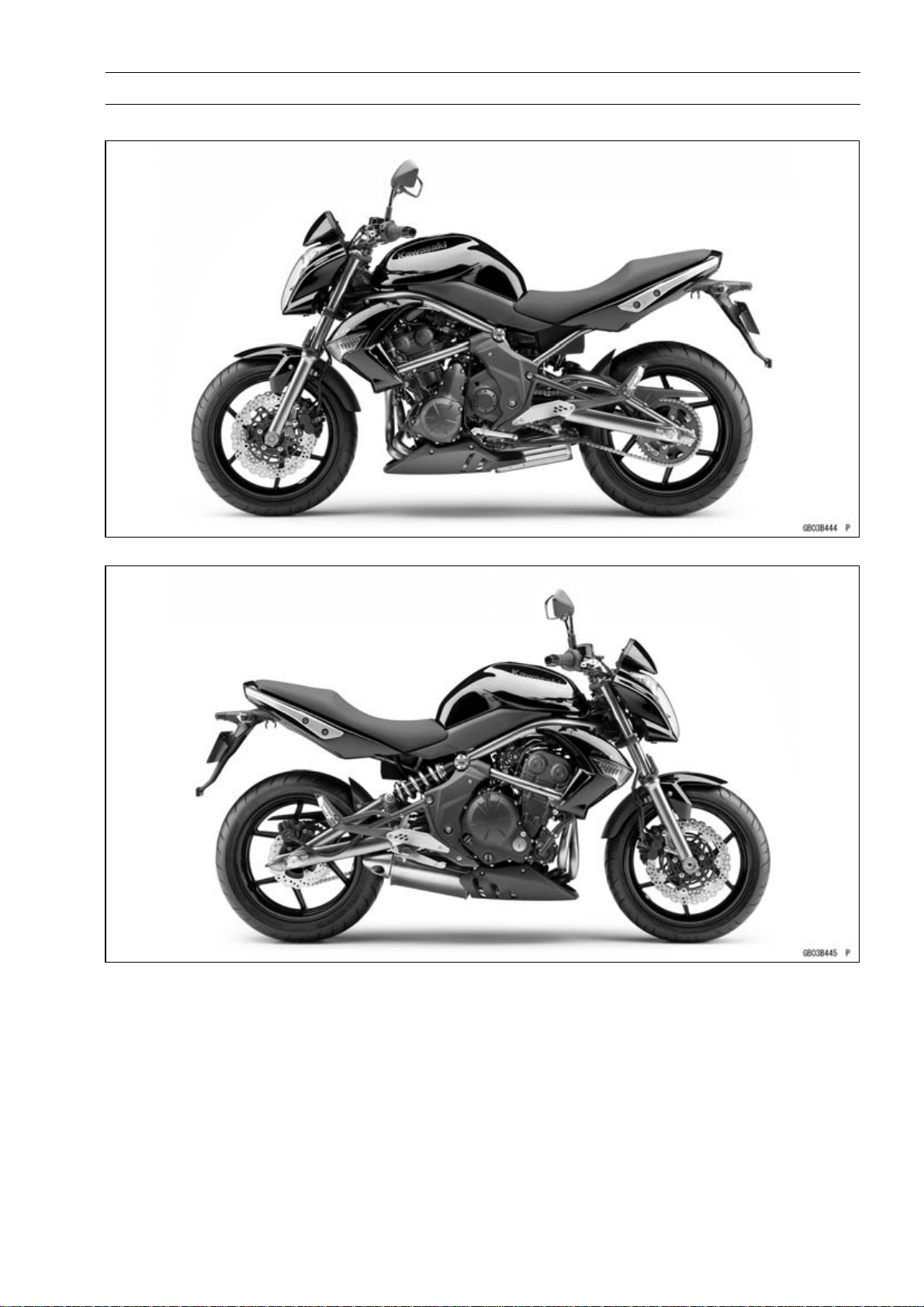
ER650C9F (EUR Models) Left Side View
GENERAL INFORMATION 1-7
ER650C9F (EUR Models) Right Side View
1-8 GENERAL INFORMATION
Model Identification
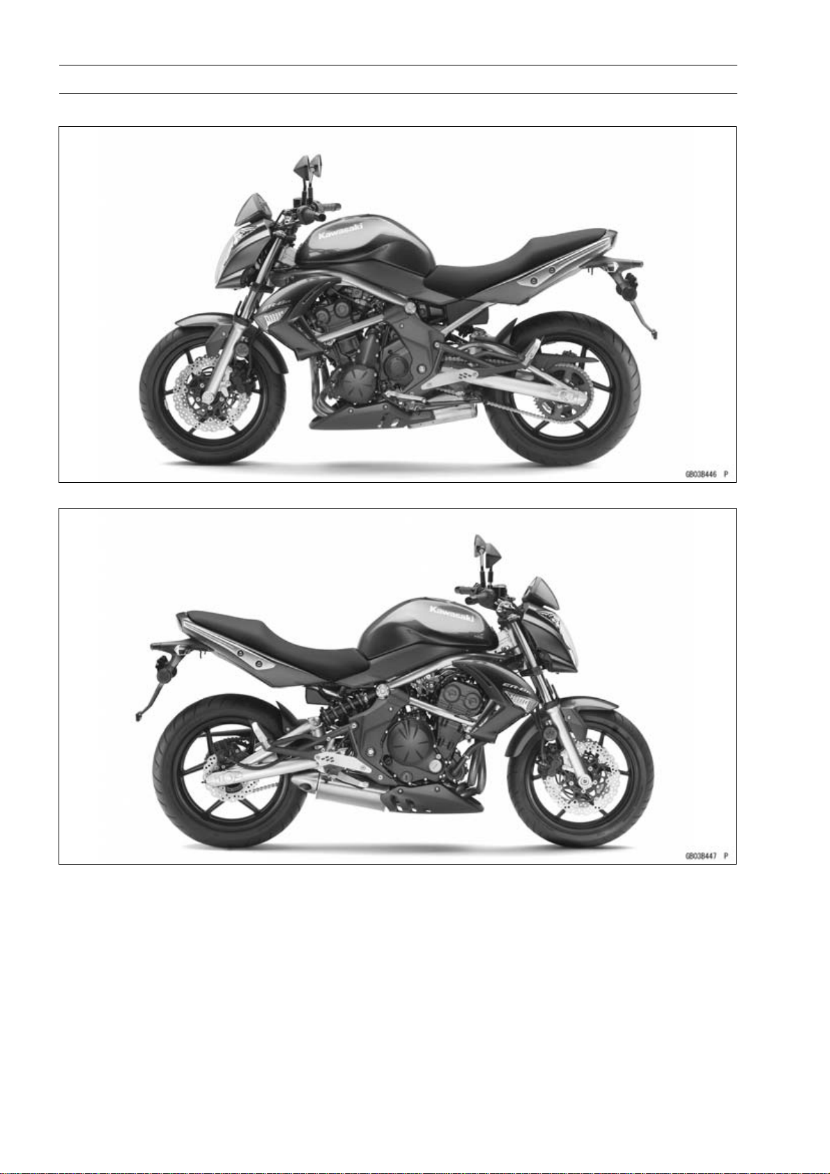
ER650C9F (US, CA Models) Left Side View
ER650C9F (US, CA Models) Right Side View
Model Identification
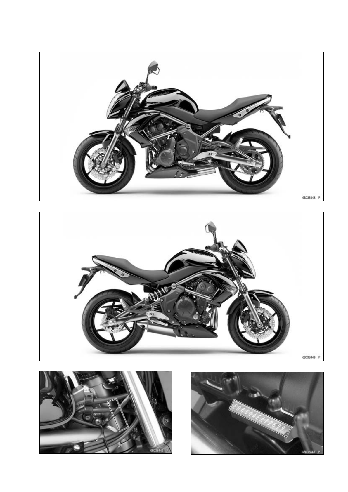
ER650D9F Left Side View
GENERAL INFORMATION 1-9
ER650D9F Right Side View
Frame Number Engine Number

1-10 GENERAL INFORMATION
General Specifications
Items ER650C9F, ER650D9F
Dimensions
Overall Length 2 100 mm (82.68 in.)
Overall Width 760 mm (29.9 in.)
Overall Height 1 100 mm (43.31 in.)
Wheelbase 1 405 mm (55.31 in.)
Road Clearance 140 mm (5.51 in.)
Seat Height 785 mm (30.9 in.)
Curb Mass:
ER650C Models: 200 kg (441 lb)
Front 100 kg (221 lb)
Rear 100 kg (221 lb)
ER650D Models:
Front
Rear 103 kg (227 lb)
Fuel Tank Capacity 15.5 L (4.10 US gal.)
Performance
Minimum Turning Radius 2.7 m (8.9 ft)
Engine
Type 4-stroke, DO HC, 2-cylinder
Cooling System Liquid-cooled
Bore and Stroke 83.0 × 60.0 mm (3.27 × 2.36 in.)
Displacement 649 cm³ (39.6 cu in.)
Compression Ratio 11.3 : 1
Maximum Horsepower 53 kW (72 PS) @8 500 r/min (rpm)
Maximum Torque 66 N·m (6.7 kgf·m, 49 ft·lb) @7 000 r/min (rpm)
Carburetion System FI (Fuel Injection), KEIHIN TTK38 × 2
Starting System
Ignition System Battery and coil (transistorized)
Timing Advance Electronically advanced (IC igniter in ECU)
Ignition Timing From 10° BTDC @1 300 r/min (rpm)
Spark Plug NGK CR9EIA-9
Cylinder Numbering Method Left to right, 1-2
Firing Order 1-2
Valve Timing:
Inlet:
Open 31° BTDC
Close 61° ABDC
Duration 272°
204 kg (450 lb)
101 kg (223 lb)
(MY) 52 kW (71 PS) @8 000 r/min (rpm)
(US, CA, CAL) – – –
(US, CA, CAL) – – –
Electric starter
To 34° BTDC @5 000 r/min (rpm)

GENERAL INFORMATION 1-11
General Specifications
Items ER650C9F, ER650D9F
Exhaust:
Open 50° BBDC
Close 30° ATDC
Duration 260°
Lubrication System Forced lubrication (semi-dry sump)
Engine Oil:
Grade API SE, SF or SG
API SH, SJ, SL or SM with JASO MA, MA1 or MA2
Viscosity SAE 10W-40
Capacity 2.4 L (2.5 US qt)
Drive Train
Primary Reduction System:
Type
Reduction R atio
Clutch Type Wet multi disc
Transmission:
Type
Gear Ratios:
1st 2.438 (39/16)
2nd 1.714 (36/21)
3rd 1.333 (32/24)
4th 1.111 (30/27)
5th 0.966 (28/29)
6th 0.852 (23/27)
Final Drive System:
Type Chain drive
Reduction R atio 3.067 (46/15)
Overall Drive Ratio 5.473 @Top gear
Frame
Type Tubular, diamond
Caster (Rake Angle) 24.5°
Trail 102 mm (4.02 in.)
Front Tire:
Type Tubeless
Size 120/70 ZR17 M/C (58W)
Rim Size 17 × 3.50
Rear Tire:
Type Tubeless
Size 160/60 ZR17 M/C (69W)
Rim Size 17 × 4.50
Front Suspension:
Type Telescopic fork
Wheel Travel 120 mm (4.72 in.)
Gear
2.095 (88/42)
6-speed, constant mesh, return shift

1-12 GENERAL INFORMATION
General Specifications
Items ER650C9F, ER650D9F
Rear Suspension:
Type Swingarm
Wheel Travel 125 mm (4.92 in.)
Brake Type:
Front Dual discs
Rear Single disc
Electrical Equipment
Battery 12 V 10 Ah
Headlight:
Type Semi-sealed beam
Bulb:
High 12 V 55 W + 55 W (quartz-halogen)
Low 12 V 55 W (quartz-halogen)
Tail/Brake Light LED
Alternator:
Type Three-phase AC
Rated Output 24 A/14 V @5 000 r/min (rpm)
Specifications are subject to change without notice, and may not apply to every country.
Unit Conversion Table
GENERAL INFORMATION 1-13
Prefixes for Units:
Prefix Symbol Power
mega M × 1 000 000
kilo k × 1 000
centi c ×0.01
milli m ×0.001
micro µ × 0.000001
Units of Mass:
kg ×2.205=lb
g × 0.03527 = oz
Units of Volume:
L × 0.2642 = gal (US)
L × 0.2200 = gal (imp)
L × 1.057 = qt (US)
L × 0.8799 = qt (imp)
L × 2.113 = pint (US)
L × 1.816 = pint (imp)
mL × 0.03381 = oz (US)
mL × 0.02816 = oz (imp)
mL × 0.06102 = cu in
Units of Length:
km × 0.6214 = mile
m × 3.281 =
mm × 0.03937 = in
ft
Units of Torque:
N·m × 0.1020 = kgf·m
N·m × 0.7376 = ft·lb
N·m × 8.851 = in·lb
kgf·m × 9.807 = N·m
kgf·m × 7.233 = ft·lb
kgf·m × 86.80 = in·lb
Units of Pressure:
kPa × 0.01020 = kgf/cm²
kPa × 0.1450 = psi
kPa × 0.7501 = cmHg
kgf/cm²
kgf/cm²
cmHg×1.333=kPa
× 98.07 = kPa
× 14.22 = psi
Units of Speed:
km/h × 0.6214 = mph
Units of Force:
N × 0.1020 = kg
N × 0.2248 = lb
kg ×9.807=N
kg ×2.205=lb
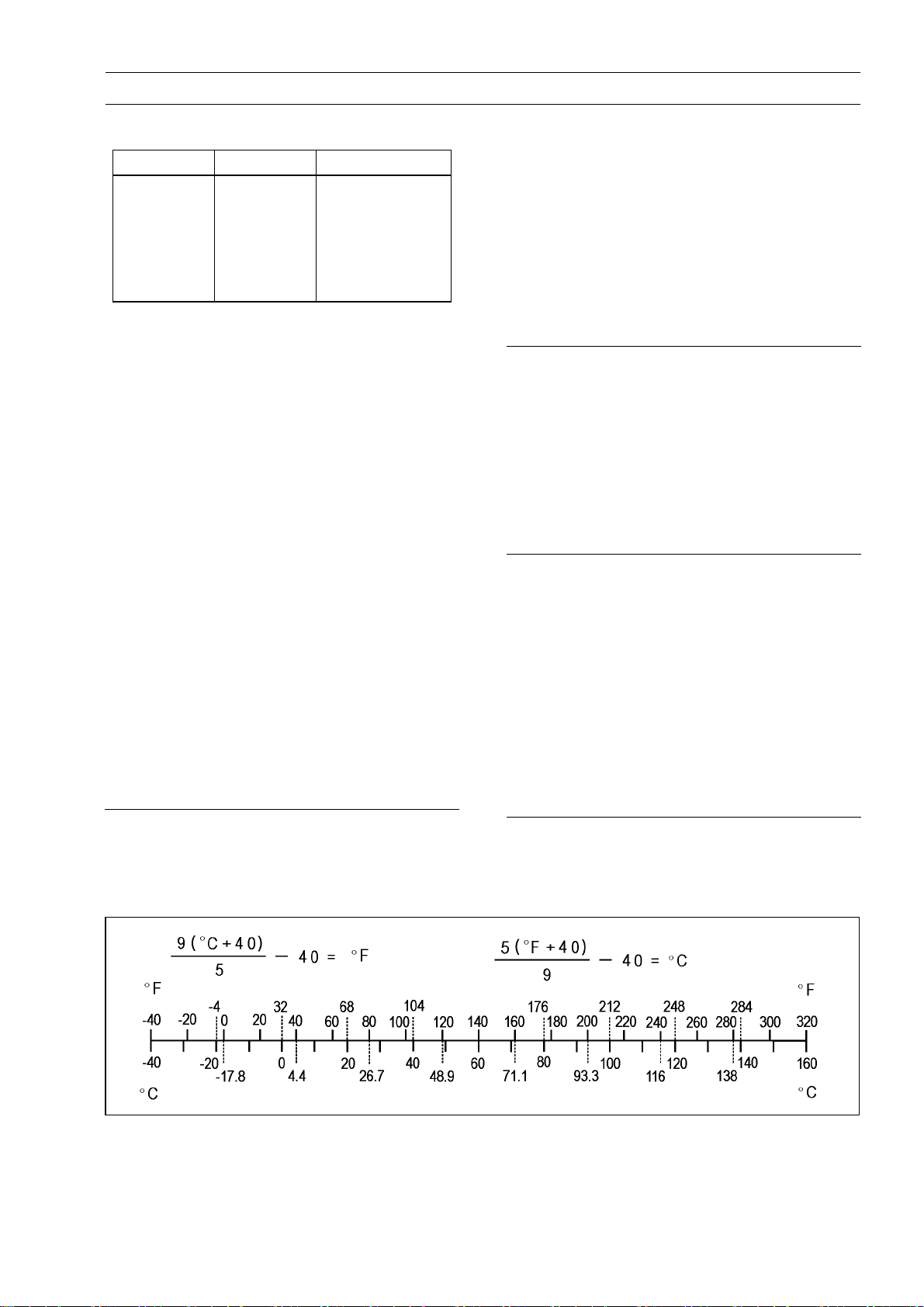
Units of Temperature:
Units of Power:
kW ×1.360=PS
kW ×1.341=HP
PS × 0.7355 = kW
PS × 0.9863 = HP


PERIODIC MAINTENANCE 2-1
Periodic Maintenance
Table of Contents
Periodic Maintenance Chart ................................................................................................... 2-3
Torque and Locking Agent...................................................................................................... 2-6
Specifications ......................................................................................................................... 2-12
Special Tools .......................................................................................................................... 2-14
Periodic Maintenance Procedures.......................................................................................... 2-15
Fuel System (DFI)................................................................................................................ 2-15
Air Cleaner Element Cleaning........................................................................................... 2-15
Throttle Control System Inspection................................................................................... 2-16
Engine Vacuum Synchronization Inspection..................................................................... 2-16
Idle Speed Inspection ....................................................................................................... 2-18
Idle Speed Adjustment...................................................................................................... 2-19
Fuel Hose Inspection (fuel leak, damage, installation condition)...................................... 2-19
Evaporative Emission Control System Inspection (CAL, SEA and TH Models) ............... 2-19
Cooling System.................................................................................................................... 2-20
Coolant Level Inspection................................................................................................... 2-20
Water Hose Damage and Installation Condition Inspection.............................................. 2-21
Engine Top End ................................................................................................................... 2-21
Va lve Clearance Inspection .............................................................................................. 2-21
Va lve Clearance Adjustment............................................................................................. 2-22
Air Suction System Damage Inspection............................................................................ 2-25
Clutch................................................................................................................................... 2-25
Clutch Operation Inspection.............................................................................................. 2-25
Wheels/Tires........................................................................................................................ 2-26
Air Pressure Inspection..................................................................................................... 2-26
Wheel/Tire Damage Inspection......................................................................................... 2-26
Tire Tread Wear, Abnormal Wear Inspection.................................................................... 2-26
Wheel Bearing Damage Inspection .................................................................................. 2-27
Final Drive............................................................................................................................ 2-28
Drive Chain Lubrication Condition Inspection................................................................... 2-28
Drive Chain Slack Inspection............................................................................................ 2-28
Drive Chain Slack Adjustment .......................................................................................... 2-29
Wheel Alignment Inspection ............................................................................................. 2-30
Drive Chain Wear Inspection ............................................................................................ 2-30
Chain Guide Inspection..................................................................................................... 2-31
Brake System ...................................................................................................................... 2-31
Brake Fluid Leak (Brake Hose and Pipe) Inspection........................................................ 2-31
Brake Hose and Pipe Damage and Installation Condition Inspection............................... 2-32
Brake Fluid Level Inspection............................................................................................. 2-32
Brake Pad Wear Inspection .............................................................................................. 2-33
Brake Operation Inspection .............................................................................................. 2-34
Brake Light Switch Operation Inspection.......................................................................... 2-34
Suspensions........................................................................................................................ 2-35
Front Forks/Rear Shock Absorber Operation Inspection.................................................. 2-35
Front Fork O il Leak Inspection.......................................................................................... 2-35
Rear Shock Absorber Oil Leak Inspection........................................................................ 2-35
Steering System ..................................................................................................................2-36
Steering Play Inspection................................................................................................... 2-36
Steering Play Adjustment.................................................................................................. 2-36
Steering Stem Bearing Lubrication................................................................................... 2-37
Electrical System................................................................................................................. 2-38
2

2-2 PERIODIC MAINTENANCE
Lights and Switches Operation Inspection........................................................................ 2-38
Headlight Aiming Inspection ............................................................................................. 2-40
Sidestand Switch Operation Inspection ............................................................................ 2-41
Engine Stop Switch Operation Inspection......................................................................... 2-42
Others.................................................................................................................................. 2-43
Chassis Parts Lubrication................................................................................................. 2-43
Bolts, Nuts and Fasteners Tightness Inspection............................................................... 2-44
Replacement Parts.............................................................................................................. 2-45
Air Cleaner Element Replacement.................................................................................... 2-45
Fuel Hose Replacement ................................................................................................... 2-45
Coolant Change................................................................................................................ 2-46
Radiator Hose and O-ring Replacement........................................................................... 2-48
Engine Oil Change............................................................................................................ 2-48
Oil Filter Replacement ...................................................................................................... 2-49
Brake Hose and Pipe Replacement.................................................................................. 2-50
Brake Fluid Change.......................................................................................................... 2-51
Master Cylinder Rubber Parts Replacement .................................................................... 2-52
Caliper Rubber Parts Replacement.................................................................................. 2-53
Spark Plug Replacement.................................................................................................. 2-56
PERIODIC MAINTENANCE 2-3
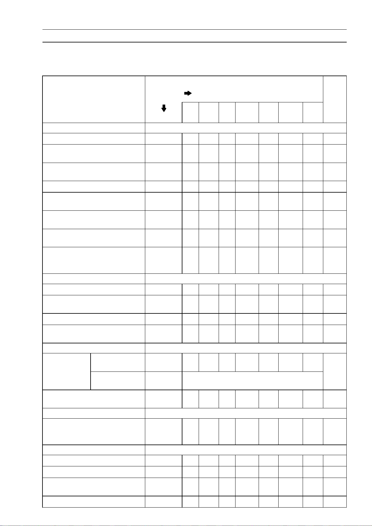
Periodic Maintenance Chart
The scheduled maintenance must be done in accordance with this chart to keep the motorcycle in
good running condition.The initial maintenance is vitally important and must not be neglected.
Periodic Inspection
FREQUENCY
ITEM Every
Fuel System
Whichever
comes first
1
(0.6)6(3.75)12(7.5)18(11.25)24(15)30(18.75)36(22.5)
* ODOMETER READING
× 1 000 km
(× 1 000 mile)
See
Page
Air cleaner element - clean
Throttle control system (play,
smooth return, no drag) - inspect
Engine vacuum synchronization
- inspect
Idle speed - inspect
Fuel leak (fuel hose and pipe) -
inspect
Fuel hose and pipe damage -
inspect
Fuel hose and pipe installation
condition - inspect
Evaporative emission control
system function (CAL, TH, SEA
Models) - inspection
Cooling System
Coolant level - inspect
Coolant leak (water hose and
pipe) - inspect
Water hose damage - inspect year
Water hose installation condition
- inspect
Engine Top End
Valve
clearance inspect
Air suction system damage inspect
Clutch
Clutch operation (play,
disengagement, engagement) inspect
Wheels and Tires
US, CA, CAL
Models
Other than US,
CA, CAL Models
year
year
year
year
year
year
• • •
• • • •
• • •
• • • •
• • • •
• • • •
• • • •
• • • • • • •
• • • •
• • • •
• • • •
• • • •
•
Every 42 000 km (26 250 mile)
• • •
• • • •
2–15
2–16
2–16
2–18
2–19
2–19
2–19
2–19
2–20
2–21
2–21
2–21
2–21
2–25
2–25
Tire air pressure - i nspect year
Wheel/tire damage - inspect
Tire tread wear, abnormal wear
- inspect
Wheel bearing damage - inspect year
• • •
• • •
• • •
• • •
2–26
2–26
2–26
2–27
2-4 PERIODIC MAINTENANCE
Periodic Maintenance Chart
FREQUENCY
ITEM Every
Final Drive
Drive chain lubrication condition
- inspect #
Drive chain slack - inspect # Every 1 000 km (600 mile) 2–28
Drive chain wear - inspect #
Chain guide wear - inspect
Brakes
Brake fluid leak (brake hose and
pipe) - inspect
Brake hose and pipe damage inspect
Brake hose and pipe installation
condition - inspect
Brake fluid level - inspect
Brake pad wear - inspect #
Brake operation (effectiveness,
play, no drag) - inspect
Brake light switch operation -
inspect
Suspension
Front forks/rear shock absorber
operation (damping and smooth
stroke) - inspect
Front forks/rear shock absorber
oil l eak - inspect
Steering
Whichever
comes first
year
year
year
6 months
year
year
1
(0.6)6(3.75)12(7.5)18(11.25)24(15)30(18.75)36(22.5)
Every 600 km (400 mile) 2–28
• • • • • • •
• • • • • • •
• • • • • • •
• • • • • • •
• • • • • •
• • • • • • •
• • • • • • •
* ODOMETER READING
× 1 000 km
(× 1 000 mile)
• • •
• • •
• • •
• • •
See
Page
2–30
2–31
2–31
2–32
2–32
2–32
2–33
2–34
2–34
2–35
2–35
Steering play - inspect year
Steering stem bearings -
lubricate
Electrical System
Lights and switches operation inspect
Headlight aiming - inspect year
Sidestand switch operation -
inspect
Engine stop switch operation -
inspect
Others
Chassis parts - lubricate year
Bolts andnuts tightness - inspect
#: Service more frequently when operating in severe conditions; dusty, wet, muddy, high speed or
frequent starting/stopping.
*: For higher odometer readings, repeat at the frequency interval established here.
2 years
year
year
year
• • • •
•
• • •
• • •
• • •
• • •
• • •
• • • •
2–36
2–37
2–38
2–40
2–41
2–42
2–43
2–44
PERIODIC MAINTENANCE 2-5
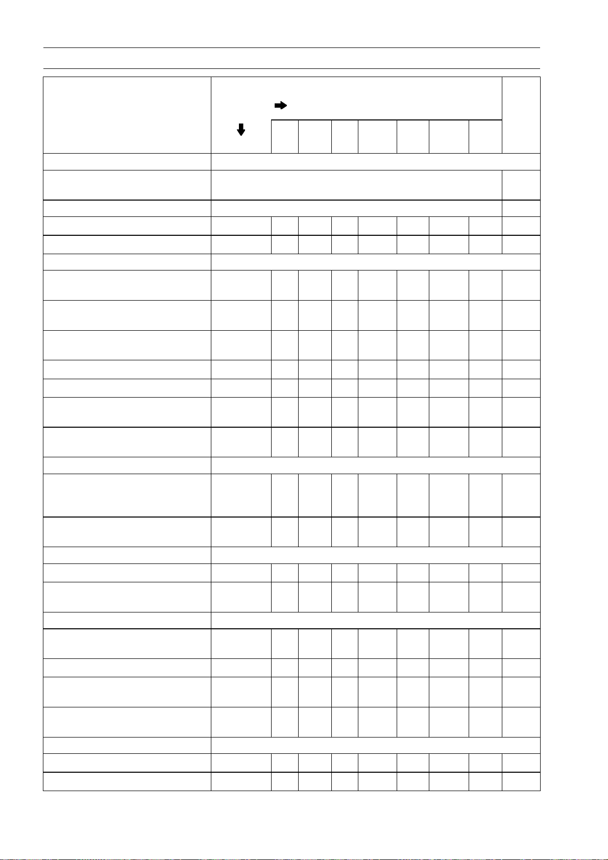
Periodic Maintenance Chart
Periodic Replacement Parts
FREQUENCY
ITEM Every
Air cleaner element # - replace 2 years 2–45
Whichever
comes
first
1
(0.6)12(7.5)24(15)36(22.5)48(30)
* ODOMETER
READING
× 1 000 km
(× 1 000 mile)
See
Page
Fuel hose - replace 4 years
Coolant - change 3 years
Radiator hose and O-ring - replace 3 years
Engine oil # - change year
Oil filter - replace year
Brake hose and pipe - replace 4 years
Brake fluid - change 2 years
Rubber parts of master cylinder and caliper - replace 4 years
Spark plug - replace
#: Service more frequently when operating in severe conditions; dusty, wet, muddy, high speed or
frequent starting/stopping.
*: For higher odometer readings, repeat at the frequency interval established here.
• • • • •
• • • • •
• • • •
•
•
• •
•
•
•
2–45
2–46
2–48
2–48
2–49
2–50
2–51
2–52
2–56
2-6 PERIODIC MAINTENANCE
Torque and Locking Agent
The following tables list the tightening torque for the major fasteners requiring use of a
non-permanent locking agent or silicone sealant etc.
Letters used in the “Remarks” column mean:
AL: Tighten the two clamp bolts alternately two times to ensure even tightening torque.
EO: Apply engine oil.
L: Apply a non-permanent locking agent to the threads.
Lh: Left-hand Threads
MO: Apply molybdenum disulfide oil solution.
(mixture of the engine oil and molybdenum disulfide grease i n a weight ratio 10 : 1)
R: Replacement Parts
S: Follow the specified tightening sequence.
Si: Apply silicone grease (ex. PBC grease).
SS: Apply silicone sealant.
Fastener
Fuel System (DFI)
Crankshaft Sensor Bolts 6.0 0.61 53 in·lb
Fuel Level Sensor Bolts 6.9 0.70 61 in·lb L
Fuel Pump Bolts 9.8 1.0 87 in·lb L, S
Oxygen Sensor (Equipped Models)
Speed Sensor Bolt
Speed S ensor Bracket Bolts 9.8 1.0 87 in·lb
Switch Housing Screws 3.5 0.36 31 in·lb
Timing Rotor Bolt 40 4.1 30
Water Temperature Sensor 12 1.2 106 in·lb
Cooling System
Baffle Plate Bolts 5.9 0.60 52 in·lb
Radiator Bolt 15 1.5 11
Water Hose Clamp Screws 2.0 0.20 18 in·lb
Thermostat Housing Bolts 9.8 1.0 87 in·lb
Water Pump Cover Bolts 9.8 1.0 87 in·lb
Water Pump Drain Bolt 9.8 1.0 87 in·lb
Water Pump Impeller Bolt 9.8 1.0 87 in·lb
Water Temperature Sensor 12 1.2 106 in·lb
Engine Top End
Air Suction Valve Cover Bolts 9.8 1.0 87 in·lb
Baffle Plate Bolts 5.9 0.60 52 in·lb
Camshaft Cap Bolts
Camshaft Chain Tensioner Cap Bolt
Camshaft Chain Tensioner Mounting Bolts 9.8 1.0 87 in·lb
Camshaft Sprocket Bolts 15 1.5 11 L
Cylinder Head Bolts (M10) 56 5.7 41 MO, S
Cylinder Head Bolts (M6) 12 1.2 106 in·lb S
Cylinder Head Cover Bolts 9.8 1.0 87 in·lb
Rear Camshaft Chain Guide Bolts 20 2.0 15 L
Spark Plugs 15 1.5 11
N·m kgf·m ft·lb
44 4.5 32
7.8 0.80 69 in·lb L
12 1.2 106 in·lb
20 2.0 15
Torque
Remarks
S

Torque and Locking Agent
PERIODIC MAINTENANCE 2-7
Fastener
Throttle Body Assy Holder Bolts 12 1.2 106 in·lb
Cylinder Bolt (M8)
Cylinder Nut
Cylinder Bolts (M6) 12 1.2 106 in·lb S
Exhaust Pipe Manifold Holder Nuts 17 1.7 13
Muffler Body Mounting Bolt (Front) 20 2.0 15
Muffler Body Mounting Bolt (Rear) 20 2.0 15
Clutch
Clutch Cable Clamp Bracket Bolt 9.8 1.0 87 in·lb
Clutch Cable Holder Bolts 9.8 1.0 87 in·lb L
Clutch Cover Bolts 9.8 1.0 87 in·lb
Clutch Hub Nut 130 13.3 96 R
Clutch Lever Clamp Bolts 7.8 0.80 69 in·lb S
Clutch Spring Bolts
Timing Rotor Bolt Cap
Oil Filler Plug – – – Hand-tighten
Oil Pump Chain Guide Bolts 12 1.2 106 in·lb L(1)
Oil Pump Sprocket Bolt 12 1.2 106 in·lb L, Lh
Timing Inspection Cap 3.9 0.40 35 in·lb
Engine Lubrication System
Engine Oil Drain Plug 30 3.1 22
Filter Plate Bolts 9.8 1.0 87 in·lb L
Holder Mounting Bolt 25 2.5 18 L
Lower Fairing Bracket Bolts 12 1.2 106 in·lb L
Oil Filter 17.5 1.8 13 EO, R
Oil Pan Bolts 12 1.2 106 in·lb S
Oil Passage Plug 20 2.0 15 L
Oil Passage Plug (M6) 3.9 0.40 35 in·lb
Oil Pipe Plate Bolt 9.8 1.0 87 in·lb L
Oil Plate Bolts 9.8 1.0 87 in·lb L
Oil Pressure Relief Valve 15 1.5 11 L
Oil Pressure Switch 15 1.5 11 SS
Oil Pump Chain Guide Bolts 12 1.2 106 in·lb L(1)
Oil Pump Cover Bolts 9.8 1.0 87 in·lb L
Oil Pump Sprocket Bolt
Engine Rem oval/Installation
Engine B racket Bolts (Left) 25 2.5 18 S
Engine Bracket Bolts (Right) 25 2.5 18 S
Engine Mounting Nut (Lower) 44 4.5 32 S
Engine M ounting Nut (Rear) 44 4.5 32 S
Engine Mounting Bolt (Left) 44 4.5 32 S
Engine M ounting Bolt (Right) 44 4.5 32 S
N·m
27.5 2.8 20
49 5.0 36
9.8 1.0 87 in·lb
4.9 0.50 43 in·lb
12 1.2 106 in·lb L, Lh
Torque
Remarks
kgf·m ft·lb
MO, S
MO, S

2-8 PERIODIC MAINTENANCE
Torque and Locking Agent
Fastener
Crankshaft/Transmission
Breather Plate Bolts 9.8 1.0 87 in·lb L
Race Holder Screw
Connecting Rod Big End Nuts see Text ← ← MO
Crankcase Bolt (M8, L = 110 mm) 27.5 2.8 20 S
Crankcase Bolt (M6, L = 32 mm) 19.6 2.0 14 S
Crankcase Bolts (M6, L = 38 mm) 19.6 2.0 14 S
Crankcase Bolts (M6, L = 45 mm) 19.6 2.0 14 S
Crankcase Bolt (M8, L = 50 mm) 27.5 2.8 20 S
Crankcase Bolts (M8, L = 60 mm) 35 3.6 26 MO, S
Crankcase Bolt (M8, L = 60 mm) 27.5 2.8 20 S
Crankcase Bolts (M8, L = 73 mm) 35 3.6 26 MO, S
Crankcase Bolts (M9, L = 113 mm) 44 4.5 32 MO, S
Crankcase Bolts (M9, L = 83 mm)
Upper Crankcase Bolt (M8, L = 120 mm)
Upper Crankcase Bolts (M 8, L = 110 mm) 27.5 2.8 20 S
Oil Pipe Bolts 9.8 1.0 87 in·lb L
Oil Plate Bolts 9.8 1.0 87 in·lb L
Shift Shaft Return Spring Pin 29 3.0 21 L
Timing Rotor Bolt 40 4.1 30
Drive Shaft Bearing Holder Screw 4.9 0.50 43 in·lb L
Gear Positioning Lever Bolt 12 1.2 106 in·lb L
Neutral Switch 15 1.5 11
Neutral Switch Holder Screw 4.9 0.50 43 in·lb L
Transmission Case Oil Nozzle 2.9 0.30 26 in·lb L
Shift Drum Bearing Holder Screws 4.9 0.50 43 in·lb L
Shift Drum Cam Bolt 12 1.2 106 in·lb L
Shift Lever Bolt 12 1.2 106 in·lb
Shift Rod Plate Bolt
Shift Shaft Cover Bolts
Shift S haft Cover Screw 4.9 0.50 43 in·lb L, S
Transmission Case Bolts 20 2.0 15
Wheels/Tires
Front Axle 108 11.0 80
Front Axle Clamp Bolt 34 3.5 25
Rear Axle Nut 108 11.0 80
Final Drive
Engine Sprocket Nut
Rear Axle Nut 108 11.0 80
Rear Sprocket Nuts 59 6.0 44
Speed Sensor Bolt
Speed S ensor Bracket Bolts
N·m
4.9 0.50 43 in·lb L
44 4.5 32
27.5 2.8 20
9.8 1.0 87 in·lb L
9.8 1.0 87 in·lb
125 12.7 92
7.8 0.80 69 in·lb L
9.8 1.0 87 in·lb
Torque
Remarks
kgf·m ft·lb
MO, S
L(3)
S
MO

Torque and Locking Agent
PERIODIC MAINTENANCE 2-9
Fastener
Brakes
Caliper Bleed Valve
Brake Hose Banjo Bolts 25 2.5 18
Brake Lever Pivot Bolt 1.0 0.10 9in·lb Si
Brake Lever Pivot Bolt Locknut 5.9 0.60 52 in·lb
Brake Disc Mounting Bolts 27 2.8 20 L
Front Brake Light Switch Screw 1.2 0.12 11 in·lb
Front Brake Reservoir Cap Screws 1.5 0.15 13 in·lb
Front Caliper Mounting Bolts 34 3.5 25
Front Master Cylinder Clamp B olts 11 1.1 97 in·lb S
Brake Pedal Bolt 8.8 0.90 78 in·lb
Rear Caliper Mounting Bolts 25 2.5 18
Rear Master Cylinder Mounting Bolts 25 2.5 18
Rear Master Cylinder Push Rod Locknut
Brake Pipe Joint Nuts (ER650D Models)
Wheel Rotation S ensor Bolts (ER650D Models) 20 2.0 15
Suspension
Front Axle Clamp Bolt 34 3.5 25
Front Fork Bottom Allen Bolts 30 3.1 22 L
Front Fork Clamp Bolts (Lower) 20 2.0 15 AL
Front Fork Clamp Bolts (Upper) 20 2.0 15
Front Fork Top Plugs 25 2.5 18
Rear Shock Absorber Bolts 59 6.0 44
Swingarm Pivot Shaft Nut 108 11.0 80
Steering
Front Fork Clamp Bolts (Lower) 20 2.0 15 AL
Front Fork Clamp Bolts (Upper) 20 2.0 15
Handlebar Holder Bolts 25 2.5 18 S
Handlebar Holder Mounting Nuts 34 3.5 25
Switch Housing Screws 3.5 0.36 31 in·lb
Steering Stem Head Bolt 108 11.0 80
Steering S tem Nut 20 2.0 15
Frame
Footpeg Stay Bolts 25 2.5 18 S
Front Fender Mounting Bolts 8.8 0.90 78 in·lb
Front Turn Signal Light Mounting Screws 1.2 0.12 11 in·lb
Grab Rail Mounting Bolts 25 2.5 18
Lower Fairing Bracket Bolts 12 1.2 106 in·lb L
Lower Fairing Mounting Bolts 8.8 0.90 78 in·lb
Seat Lock Mounting Screws 1.2 0.12 11 in·lb
Sidestand Bolt 44 4.5 32
Sidestand Sw itch Bolt 8.8 0.90 78 in·lb L
N·m
7.8 0.80 69 in·lb
17 1.7 13
18 1.8 13
Torque
Remarks
kgf·m ft·lb

2-10 PERIODIC MAINTENANCE
Torque and Locking Agent
Fastener
Electrical System
Tail/Brake Light Mounting Bolts 8.8 0.90 78 in·lb
License Plate Light Mounting Screws 1.2 0.12 11 in·lb
Alternator Cover Bolts 9.8 1.0 87 in·lb
Alternator Lead Holding Plate Bolt 9.8 1.0 87 in·lb L
Alternator Rotor Bolt 155 15.8 114 MO
Engine Ground Lead Terminal Bolt 9.8 1.0 87 in·lb
Front Brake Light Switch Screw 1.2 0.12 11 in·lb
Front Turn Signal Light Mounting Screws 1.2 0.12 11 in·lb
Fuel Pump Bolts 9.8 1.0 87 in·lb L, S
Meter Cover Screws 1.2 0.12 11 in·lb
Regulator/Rectifier Bolts 8.8 0.90 78 in·lb
Switch Housing Screws 3.5 0.36 31 in·lb
Sidestand Switch Bolt
Starter Motor Terminal Nut
Starter Motor Clutch Bolts 34 3.5 25 L
Starter Motor Mounting Bolts 9.8 1.0 87 in·lb L
Starter Motor Terminal Locknut 11 1.1 97 in·lb
Starter Motor Through Bolts 5.0 0.51 44 in·lb
Stator Coil Bolts 12 1.2 106 in·lb L
Crankshaft Sensor Bolts 6.0 0.61 53 in·lb
Neutral Switch 15 1.5 11
Oil Pressure Switch 15 1.5 11 SS
Oxygen Sensor (Equipped Models) 44 4.5 32
Spark Plugs 15 1.5 11
Speed Sensor Bolt
Timing Rotor Bolt 40 4.1 30
Water Temperature Sensor 12 1.2 106 in·lb
Fuel Level Sensor Bolts
N·m
8.8 0.90 78 in·lb L
6.0 0.61 53 in·lb
7.8 0.80 69 in·lb L
6.9 0.70 61 in·lb L
Torque
Remarks
kgf·m ft·lb

PERIODIC MAINTENANCE 2-11
Torque and Locking Agent
The table below, relatingtighteningtorque to thread diameter, lists thebasic torque for the bolts and
nuts. Use this table for only the bolts and nuts which do not require a specific torque value. All of the
values are for use with dry solvent-cleaned threads.
Basic Torque for General Fasteners
Threads D iameter
(mm)
5 3.4 ∼ 4.9 0.35 ∼ 0.50 30 ∼ 43 in·lb
6 5.9 ∼ 7.8 0.60 ∼ 0.80 52 ∼ 69 in·lb
8 14 ∼ 19 1.4 ∼ 1.9 10.0 ∼ 13.5
10 25 ∼ 34 2.6 ∼ 3.5 19.0 ∼ 25
12 44 ∼ 61 4.5 ∼ 6.2 33 ∼ 45
14 73 ∼ 98 7.4 ∼ 10.0 54 ∼ 72
16 115 ∼ 155 11.5 ∼ 16.0 83 ∼ 115
18 165 ∼ 225 17.0 ∼ 23.0 125 ∼ 165
20 225 ∼ 325 23.0 ∼ 33.0 165 ∼ 240
N·m kgf·m ft·lb
Torque

2-12 PERIODIC MAINTENANCE
Specifications
Item Standard Service Limit
Fuel System (DFI)
Throttle Grip Free Play 2 ∼ 3 mm (0.08 ∼ 0.12 in.) –––
Idle Speed 1 300 ±50 r/min (rpm) –––
Bypass Screws (Turn out) 0 ∼ 2 1/2 (for reference) –––
Engine Vacuum 35.3 ±1.3 kPa (265 ±10 mmHg) –––
Air Cleaner Element Polyurethane Foam –––
Cooling System
Coolant:
Type (recommended) Permanent type of antifreeze
Color G reen
Mixed Ratio S oft water 50%, Coolant 50% –––
Freezing Point –35°C (–31°F) –––
Total Amount 1.2 L (1.3 US qt) –––
Engine Top End
Valve Clearance:
Exhaust 0.22 ∼ 0.31 mm (0.0087 ∼ 0.0122 in.) –––
Inlet 0.15 ∼ 0.21 mm (0.0059 ∼ 0.0083 in.) –––
Clutch
Clutch Lever Free Play 2 ∼ 3 mm (0.08 ∼ 0.12 in.) –––
Engine Lubrication System
Engine Oil:
Type API SE, SF or SG –––
API SH, SJ, SL or SM wi th JASO MA,
MA1 or MA2
Viscosity SAE 10W-40 –––
Capacity 1.7 L (1.8 US qt) (when filter is not
removed)
1.9 L (2.0 US qt) (when filter is removed) –––
2.4 L (2.5 US qt) (when engine is
completely dry)
Level Between upper and lower level lines
(after idling or running)
Wheels/Tires
Tread Depth:
Front 4.5 mm (0.18 in.) 1 mm (0.04 in.),
Rear 6.4 mm (0.25 in.) Up to 130 km/h (80 mph):
Over 130 km/h (80 mph):
Air Pressure (when Cold):
Front Up to 180 kg (397 lb) load:
225 kPa (2.25 kgf/cm², 32 psi)
–––
–––
–––
–––
–––
(AT, CH, DE)
1.6 mm (0.06 in.)
2 mm (0.08 in.),
3 mm (0.12 in.)
–––

PERIODIC MAINTENANCE 2-13
Specifications
Item Standard Service Limit
Rear Up to 180 kg (397 lb) load:
250 kPa (2.50 kgf/cm², 36 psi)
Final Drive
Drive Chain Slack 25 ∼ 35 mm (1.0 ∼ 1.4 in.) –––
Chain 20-link Length 317.5 ∼ 318.2 mm (12.50 ∼ 12.53 in.) 323 mm (12.7 in.)
Standard Chain:
Make
Type DID 520VP2-T –––
Link 114 links –––
Brakes
Brake Fluid:
Grade DOT4 –––
Brake Pad Lining
Thickness:
Front 4.5 mm (0.18 in.) 1 mm (0.04 in.)
Rear 5.0 m m (0.20 in.) 1 mm (0.04 in.)
Brake Light Timing:
Front Pulled O N –––
Rear ON after about 10 mm (0.39 in.) of
Electrical System
Spark Plug:
Type NGK CR9EIA-9 –––
DAIDO
pedal travel
–––
–––
–––

2-14 PERIODIC MAINTENANCE
Special Tools
Inside Circlip Pliers:
57001-143
Steering Stem Nut Wrench:
57001-1100
Oil Fil ter Wrench:
57001-1249
Throttle Sensor Setting Adapter:
57001-1538
Extension Tube:
57001-1578
Pilot Screw Adjuster, E:
57001-1603
Vacuum Gauge:
57001-1369

Periodic Maintenance Procedures
Fuel System (DFI)
Air Cleaner Element Cleaning
NOTE
In dusty areas, the element should be cleaned more
○
frequently than the recommended interval.
After riding through rain or on muddily roads, the ele-
○
ment should be cleaned immediately.
WARNING
If dirt or dust is allowed t o pass through into the
throttle body assy, the throttle may become stuck,
possibly causing accident.
CAUTION
If dirt gets through into the engine, excessive engine wear and possibly engine damage will occur.
Remove:
•
Fuel Tank (see Fuel Tank Removal in the Fuel System
(DFI) chapter)
Air Switching Valve Hose [A]
Air Cleaner Element Screw [B]
Air Cleaner Element [C]
PERIODIC MAINTENANCE 2-15
Remove:
•
Plastic Holder [A]
Element [B]
WARNING
Clean the element in a well-ventilated area, and
make sure that there are no sparks or flame anywhere near the working area.
Because of the danger of highly flammable liquids,
do not use gasoline or a low-flash point solvent to
clean the element.
Clean theelement [A] ina bath ofhigh-flash point solvent,
•
and then dry it with compressed air or by shaking it.
After cleaning, saturate a clean, lint-free towel with SE,
•
SF, orSG classSAE30 oiland applyt he oilto the element
by tapping the element outside with the towel.
Visually inspect the element for tears or breaks.
•
If the element has any tears or breaks, replace the ele-
•
ment with a new one.
Install the element.
•

2-16 PERIODIC MAINTENANCE
Periodic Maintenance Procedures
Throttle Control System Inspection
Check that the throttle grip [A] moves smoothly from full
•
open to close, and the throttle closes quickly and completely by the return spring in all steering positions.
Ifthe throttlegrip doesnot returnproperly,check thethrottle cable routing, grip free play, and cable damage. Then
lubricate the throttle cable.
Check the throttle grip free play [B].
•
Throttle Grip Free Play
Standard: 2 ∼ 3 mm (0.08 ∼ 0.12 in.)
If the free play is incorrect, adjust the throttle cable as
follows.
Loosen the locknut[A] at the upper end of the accelerator
•
cable.
Turntheadjuster[B] incompletelyso astogive thethrottle
•
grip plenty of play.
Loosen the locknut [A] at the middle of the decelerator
•
cable.
Turntheadjuster [B]until thereis noplay whenthe throttle
•
grip is completely closed.
Tighten the locknut.
•
Turn the accelerator cable adjuster until the proper
•
amount of throttle grip free play is obtained.
Tighten the locknut.
•
Engine Vacuum Synchronization Inspection
NOTE
Theseprocedures areexplained onthe assumptionthat
○
the inlet and exhaust systems of the engine are in good
condition.
Situate the motorcycle so that it is vertical.
•
Disconnect the inlet air pressure sensor hose temporary.
•
Pull off the rubber caps [A] from the fitting of each throttle
•
body.
CAUTION
Connect the inlet air pressure sensor hose on the
left fitting of the throttle body.

Periodic Maintenance Procedures
Connect a vacuum gauge (special tool) and hoses [A] to
•
the fittings of the throttle body as shown in the figure.
Special Tool - Vacuum Gauge: 57001-1369
Connect a highly accurate tachometer to one of the stick
•
coil primary leads.
Start the engine and warm it up thoroughly.
•
Checkthe idlespeed, usinga highlyaccurate tachometer.
•
Open and close the throttle.
•
If the idle speed is out of the specified range, adjust it.
CAUTION
Do not measure the idle speed by the tachometerof
the meter unit.
PERIODIC MAINTENANCE 2-17
While idlingthe engine, inspect theengine vacuum, using
•
the vacuum gauge.
Engine Vacuum
Standard: 35.3 ±1.3 kPa (265 ±10 mmHg) at Idle Speed
1300±50r/min(rpm)
If any one vacuum is not within the specification, turn in
the bypass screws until it seats fully but not tightly.
Special Tool - Pilot Screw Adjuster, E [A]: 57001-1603
CAUTION
Do not over tighten them. They could be damaged,
requiring replacement.
Turnout the bypass screw of the higher vacuum between
•
#1 [A] and #2 [B] to the lower vacuum.
Open and close the throttle valves after each measure-
•
ment and adjust the idle speed as necessary.
Inspect the vacuums as before.
•
If both vacuums are withinthe specification, finish the engine vacuum synchronization.
Ifany vacuumcan notbeadjustedwithinthe specification,
remove the bypass screws #1, #2 and clean them.

2-18 PERIODIC MAINTENANCE
Periodic Maintenance Procedures
Remove the bypass screw [A], spring [B], washer [C] and
•
O-ring [D].
Check the bypass screw and its hole for carbon deposits.
•
If any carbon accumulates, wipe the carbon off from the
bypassscrew and thehole, using acotton padpenetrated
with a high-flash point solvent.
Replace the O-ring with a new one.
•
Check the tapered portion [E] of the bypass screw for
•
wear or damage.
If the bypass screw is worn or damaged, replace it.
Turn in the bypass screw until it seats fully but not tightly.
•
Repeat the same procedure for other bypass s crews.
•
Repeat the synchronization.
•
If the vacuums are correct, check the output voltage of
themainthrottle sensor(see Main ThrottleSensor Output
Voltage Inspection in the Fuel System (DFI) chapter).
Special Tool - Throttle Sensor Setting Adapter: 57001
-1538
Main Throttle Sensor Output Voltage
Connections to Adapter:
Meter (+) → R (Sensor Y/W) lead
Meter (–) → W (Sensor BR/BK) lead
Standard: DC 1.005 ∼ 1.035 V at idle throttle opening
If the output voltage is out of the range, check the main
throttlesensor input voltage(see Main ThrottleSensor Input VoltageInspection in the Fuel System (DFI) chapter).
Remove the vacuum gauge hoses and install the rubber
•
caps onto the original positions.
Idle Speed Inspection
Start the engine and warm it up thoroughly.
•
With the engine idling, turn [A] the handlebar to both
•
sides.
If handlebar movement changes the idle speed, the
throttle cables may be improperly adjusted or incorrectly
routed or damaged. Be sure to correct any of these
conditions before riding (see Throttle Control System
Inspection and Cable, Wire, and Hose Routing section in
the Appendix chapter).
WARNING
Operation with improperly adjusted, incorrectly
routed or damaged cables could result in an unsafe
riding condition.
Check idle speed.
•
If the idle speed is out of the specified range, adjust it.
Idle Speed
Standard: 1 300 ±50 r/min (rpm)

Periodic Maintenance Procedures
Idle Speed Adjustment
Start the engine and warm it up thoroughly.
•
Turnthe adjustingscrew [A] until theidle speed iscorrect.
•
Open and close the throttle a few times to make sure that
○
the idle speed is within the specified range. Readjust if
necessary.
Fuel Hose Inspection (fuel leak, damage, installation condition)
If the motorcycle is not properly handled, the high pres-
○
sure inside the fuel line can cause fuel to leak [A] or the
hose to burst. Remove the fuel tank (see Fuel Tank Removal in the Fuel System (DFI) chapter) and check the
fuel hose.
Replace the fuel hose if any fraying, cracks [B] or bulges
[C] are noticed.
PERIODIC MAINTENANCE 2-19
Checkthat thehoses arerouted accordingto Cable,Wire,
•
and Hose Routing section in the Appendix chapter.
Replace the hose if it has been sharply bent or kinked.
Hose Joints [A]
Fuel Hose [B]
eck that the hose joints are securely connected.
Ch
•
Push and pull [A] the hose joint [B] back and forth more
○
than two times, and make sure it is locked.
If it does not locked, reinstall the hose joint.
WARNING
Makesure the hose jointis installedcorrectly on the
delivery pipe by sliding the joint, or the fuel could
leak.
Evaporative Emission Control System Inspection (CAL, SEA and TH Models)
Inspect the canister as follows.
•
Remove the canister cover on the left side of the frame.
○
Remove the canister [A], and disconnect the hoses from
○
the canister.
Visually inspect the canister for cracks or other damage.
○
If the canister has any cracks or bad damage, replace it
with a new one.
NOTE
Thecanister is designedtoworkwell throughthe motor-
○
cycle’s life without any maintenance if it is used under
normal conditions.

2-20 PERIODIC MAINTENANCE
Periodic Maintenance Procedures
Check the liquid/vapor separator as follows.
•
Remove the canister cover on the left side of the frame.
○
Disconnectthe hoses from theseparator, andremove the
○
separator [A].
Visually inspect the separator for cracks and other dam-
○
age.
If the separator hasany cracks or damage, replace it with
a new one.
To prevent the gasoline from flowing into or out of the
○
canister, hold the separator perpendicular to the ground.
Check the hoses of the evaporative emissionc ontrol sys-
•
tem as follows.
Check that the hoses are securely connected and clips
○
are in position.
Replace any kinked, deteriorated or damaged hoses.
○
Route the hoses according to Cable, Wire, and Hose
○
Routing section in the Appendix chapter.
When installing the hoses, avoid sharp bending, kinking,
○
flatteningor twisting, and route thehoseswith a minimum
ofbending sothat theemission flowwillnot beobstructed.
Cooling System
Coolant Level Inspection
NOTE
Check the level when the engine is cold (room or ambi-
○
ent temperature).
Check the coolant level in the reserve tank [A] with the
•
motorcycleheld perpendicular(do not usethe sidestand).
If the coolant level is lower than the “L” level line [B], removetheright middlefairing (seeMiddleFairing Removal
in the Frame chapter) and unscrew the reserve tank cap,
and add coolant to the “F” level line [C].
“L”: Low
“F”: Full
CAUTION
For refilling, add the specified mixture of coolant
and soft water. Adding w ater alone dilutes the
coolant and degrades its anticorrosion properties.
The diluted coolant can attack the aluminum engine parts. In an emergency, soft water alone can
be added. But the diluted coolant must be returned
to the correct mixture ratio within a few days.
If coolant must be added often or the reservoir tank
has runcompletely dry,there is probablyleakage in
the cooling system. Check the system for leaks.
Coolant ruins painted surfaces. Immediately wash
away any coolant that spills on the frame, engine,
wheels or other painted parts.

Periodic Maintenance Procedures
Water Hose Damage and Installation Condition Inspection
The high pressure inside the water hose can cause
○
coolant to leak [A] or the hose to burst if the line is not
properly maintained.
Visually inspect the hoses for signs of deterioration.
•
Squeeze the hoses. A hose should not be hard and
brittle, nor should it be soft or swollen.
Replace the hose if any fraying, cracks [B] or bulges [C]
are noticed.
Check that thehoses are securely connected andclamps
•
are tightened correctly.
Torque - Water Hose Clamp Screws: 2.0 N·m (0.20 kgf·m,
18 in·lb)
Engine Top End
Valve Clearance Inspection
NOTE
Valve clearance must be checked and adjusted when
○
the engine is cold (room temperature).
PERIODIC MAINTENANCE 2-21
Remove:
•
Cylinder Head Cover (see Cylinder Head Cover Removal in the Engine Top End chapter)
Timing Inspection Cap [A]
Timing Rotor Bolt Cap [B]
Check the valve clearance when the pistons are at TDC.
•
The pistons are numbered beginning with the engine left
○
side.
Using a wrench on the timing rotor bolt, turn the crank-
•
shaft clockwise until the 1/T mark line [A] on the timing
rotor is aligned with thenotch [B] in the edge of the timing
inspection hole [C] in the clutch cover for #1 piston and
2/T mark line [D] for #2 piston.
Measure the valve clearance of the valves for which the
○
cams [A] are turned away from each other.

2-22 PERIODIC MAINTENANCE
Periodic Maintenance Procedures
Using the thickness gauge [A], measure the valve clear-
•
ance between cam and valve lifter.
Valve Clearance
Standard:
Exhaust 0.22 ∼ 0.31 mm (0.0087 ∼ 0.0122 in.)
Inlet 0.15 ∼ 0.21 mm (0.0059 ∼ 0.0083 in.)
Each piston has two inlet and two exhaust valves. Mea-
○
sure these two inlet or exhaust valves at the same crankshaft position.
NOTE
Check the valve clearance using this method only.
○
Checking the clearance at any other cam position may
result in improper valve
Valve Clearance Measuring Position
#1 Piston TDC at End of Compression Stroke:
Inlet valve clearances of #1 piston, and
Exhaust valve clearances of #1 piston
#2 Piston TDC at End of Compression Stroke:
Inlet valve clearances of #2 piston, and
Exhaust valve clearances of #2 piston
clearance.
If the valve clearance is not within the specified range,
first record the clearance, and then adjust it.
Valve Clearance Adjustment
To change the valve clearance, remove the camshaft
•
chain tensioner, camshafts and valve lifters. Replace the
shim with one of a different thickness.
NOTE
Mark and record the locations of the valve lifters and
○
shims so that they can be reinstalled in their original
positions.
To select a new shim which brings the valve clearance
•
within the specified range, refer to the Valve Clearance
Adjustment Charts.
Apply a thin coat of molybdenum disulfide grease to the
•
valve lifters.
Installthe camshafts. Be sureto timethe camshafts prop-
•
erly (see Camshaft Installation in the Engine Top End
chapter).
Remeasure any valve clearance that was adjusted.
•
Readjust if necessary.
CAUTION
Do not put shim stock under the shim. This may
cause the shim to pop out at high rpm, causing extensive engine damage.
Do notgrind theshim. This maycause it to fracture,
causing extensive engine damage.

PERIODIC MAINTENANCE 2-23
Periodic Maintenance Procedures
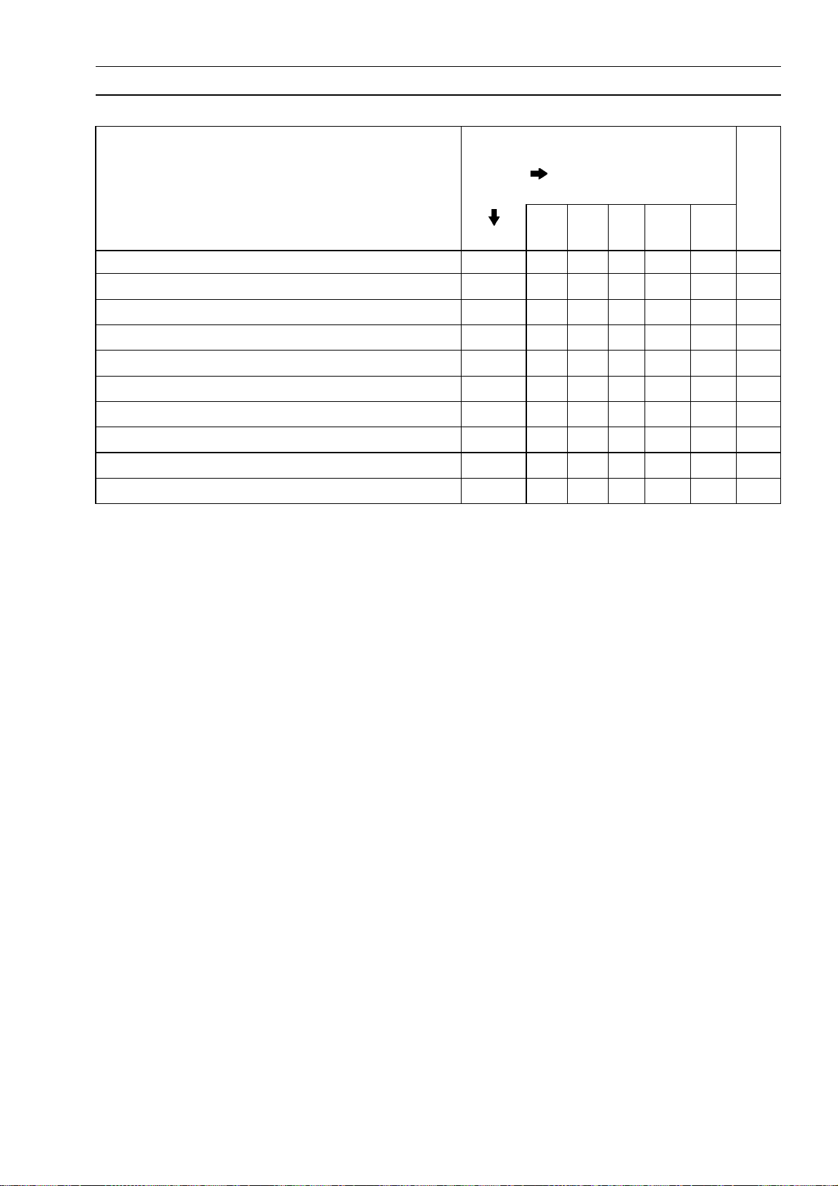
VALVE CLEARANCE ADJUSTMENT CH ART INLET VALVE
1. Measure the clearance (when engine is cold).
2. Check present shim size.
3. Match clearance in vertical column with present shim size in horizontal column.
4. Install the shim specified where the lines intersect. This shim will give the proper clearance.
Example: Present shim is 2.95 mm .
Measured clearance is 0.42 mm.
Replace 2.95 mm shim with 3.20 mm shim.
5. Remeasure the valve clearance and readjust if necessary.

2-24 PERIODIC MAINTENANCE
Periodic Maintenance Procedures
VALV E CLEARANCE ADJUSTMENT CHART EXHAUST VALVE
1. Measure t he clearance (when eng
2. Check present shim size.
3. Match clearance in vertical column with present shim size in horizontal column.
4. Install the shim specified w
Example: Present shim is 2.95 mm.
Measured clearance is 0.47 mm.
Replace 2.95 mm shim with 3.15 mm shim.
5. Remeasure the valve clearance and readjust if necessary.
here the lines intersect. This shim will give the proper clearance.
ine is cold).

Periodic Maintenance Procedures
Air Suction System Damage Inspection
Remove:
•
Fuel Tank (see Fuel Tank Removal in the Fuel System
(DFI) chapter)
Fuel Hose (see Fuel Hose Replacement)
Connect the following parts temporary.
•
Fuel Pump Lead Connector [ A]
Fuel Level Sensor Lead Connector [B]
ExtensionTube[C]
Special Tool - Extension Tube: 57001-1578
Pull the air switching valve hose [D] out of the air cleaner
•
housing.
Start the engine and run it at idle speed.
•
Plug [A] the air switching valve hose end with your finger
•
and feel vacuum pulsing in the hose.
If there is no vacuum pulsation, check the hose line for
leak. If there is no leak, check the air switching valve
(see Air Switching Valve Unit Test in the Electrical System chapter) or air suction valve (see Air Suction Valve
Inspection in the Engine Top End chapter).
PERIODIC MAINTENANCE 2-25
Clutch
Clutch Operation Inspection
Pull the clutch lever just enough to take up the free play
•
[A].
Measure the gap between the lever and the lever holder.
•
If the gap is too wide, the clutch may not release fully. If
the gap is too narrow, the clutch may not engage fully. In
either case, adjust it.
Clutch Lever Free Play
Standard: 2 ∼ 3mm(0.08∼ 0.12 in.)
WARNING
To avoid a serious burn, never touch the engine or
exhaust
Tur
•
of threads are visible.
pipe during clutch adjustment.
n the adjuster[A] so that 5 ∼ 6 mm (0.20 ∼ 0.24 in.) [B]

2-26 PERIODIC MAINTENANCE
Periodic Maintenance Procedures
Open the clamp [A].
•
Slide the dust cover [B] out of place.
•
Loosen the locknut [C].
•
Turn the adjusting nut [D] until the free play is correct.
•
WARNING
Be sure that the outer cable end at the clutch lever
is fully seated in the adjuster at the clutch lever, or
it could slip into place later, creating enough cable
play to prevent clutch disengagement.
Tighten the locknut, and slip the dust cover back onto
•
place.
After the adjustment, start the engine and check that the
•
clutch does not slip and that it releases properly.
Wheels/Tires
Air Pressure Inspection
Remove the air valve cap.
•
Measure the tire air pressure with an air pressure gauge
•
[A] when the tires are cold (that is, when the motorcycle
has not been ridden more than a mile during the past 3
hours).
Install the air valve cap.
•
Adjust the tireair pressure according to the specifications
if necessary.
Air Pressure (when Cold)
Front:
Rear:
Wheel/Tire Damage Inspection
Remove any imbedded stones [A] or other foreign parti-
•
cles [B] fr
Visually inspect the tire for cracks and cuts, and replace
•
the tire if necessary. Swelling or high spots indicate internal dam
Visuallyinspect thewheel forcracks, cutsand dents dam-
•
age.
ny damage is found, replace the wheel if necessary.
If a
Tire Tread Wear, Abnormal Wear Inspection
As the tire tread wears down, the tire becomes more susceptible to puncture and failure. An accepted estimate is
that90% of alltire failuresoccur duringthe last10% of tread
life (90% worn). So it is false economy and unsafe to use
the tires until they are bald.
Measure the tread depth at the center of the tread with a
•
depth gauge [A]. Since the tire may wear unevenly, take
measurement at several places.
If any measurement is less than the service limit, replace
the tire(see Tire Removal/Installationin the Wheels/Tires
chapter).
Up to 180 kg (397 lb)
225 kPa (2.25 kgf/cm², 32 psi)
Up to 180 kg (397 lb)
250 kPa (2.50 kgf/cm²,
om tread.
age, requiring tire replacement.
36 psi)

Periodic Maintenance Procedures
Tread Depth
Standard:
Front 4.5 mm (0.18 in.)
Rear 6.4 mm (0.25 in.)
Service Limit:
Front
Rear
1 mm (0.04 in.)
(AT, CH, DE) 1.6 mm (0.06 in.)
2 mm (0.08 in.)
(Up to 13 0 km/h (80 mph))
3 mm (0.12 in.)
(Over 130 km/h (80 mph))
WARNING
To ensure safe handling and stability, use only the
recommended standard tires for replacement, inflated to the standard pressure.
NOTE
Most countries may have their own regulations a mini-
○
mum tire tread depth: be sure to follow them.
Check and balance the wheel when a tire is replaced
○
with a new one.
PERIODIC MAINTENANCE 2-27
Wheel Bearing Damage Inspection
Raise the front wheel off the gro
•
Front Wheel Removal in the Wheels/Tires chapter).
Turn the handlebar all the way to the right or left.
•
Inspect
•
ing and pulling [A] the wheel.
Spin [B] the front wheel lightly, and check for smoothly
•
urn, roughness, binding or noise.
t
If roughness, binding or noise is found, remove the front
wheel and inspect the wheel bearing (see Front Wheel
Removal, Hub Bearing Inspection in the Wheels/Tires
chapter).
Raise the rear wheel off t he ground with the stand (see
•
Rear Wheel Removal in the Wheels/Tires chapter).
Inspect the roughness of the rear wheel bearing by push-
•
ing and pulling [A] the wheel.
Spin [B] the rear wheel lightly, and check for smoothly
•
turn, r oughness, binding or noise.
If roughness, binding or noise is found, remove the rear
wheeland inspectthewheel bearing(seeRear WheelRemoval, Hub Bearing Inspection in the Wheels/Tires chapter) and coupling (see Coupling Bearing Inspection in the
Final Drive chapter).
the roughnessof the front wheelbearing by push-
und with the jack (see

2-28 PERIODIC MAINTENANCE
Periodic Maintenance Procedures
Final Drive
Drive Chain Lubrication Condition Inspection
If a special lubricant is not available, a heavy oil such as
•
SAE 90 is preferred to a lighter oil because it will stay on
the chain longer and provide better lubrication.
If the chain appears especially dirty, clean it before lubri-
•
cation.
CAUTION
The O-rings between the side plates seal in the lu-
bricant between the pin and the bushing. To avoid
damaging the O-rings and resultant loss of lubri-
cant, observe the following rules.
Use only kerosene or diesel oil for cleaning an O
-ring of the drive chain. Any other cleaning solu-
tion such as gasoline will cause deterioration and
swelling of the O -ring. Immediately blow the chain
dry with compressed air after cleaning. Complete
cleaning and drying the chain within 10 minutes.
Applyoilto the sidesof the rollers sothat oil willpenetrate
•
to therollersand bushings. Apply the oilto the O-rings so
that the O-rings will be coated with oil.
Wipe off any excess oil.
•
Oil Applied Areas [A]
O-rings [B]
Drive Chain Slack Inspection
NOTE
Check the slack with the motorcycle setting on its side-
○
stand.
Clean the chain if it is dirty, and lubricate it if it appears
○
dry.
Checkthe wheelalignment (seeWheelAlignment Inspec-
•
tion).
Rotate the rear wheel to find the position where the chain
•
is tightest.
Measure the vertical movement (chain slack) [A] midway
•
between the sprockets.
If the chain slack exceeds the standard, adjust it.
ain Slack
Ch
tandard:25 ∼ 35 mm (1.0 ∼ 1.4 in.)
S

Periodic Maintenance Procedures
Drive Chain Slack Adjustment
Raise the rear wheel off the ground with the stand.
•
Remove the cotter pin [A], and loosen the axle nut [B].
•
Loosen the both chain adjuster locknuts [C].
•
If the chain is too loose, turn out the right and left chain
adjusters [D] evenly.
If the chain is too tight, turn in the right and left chain
adjusters evenly, and kick the wheel forward.
Turn both chain adjusters evenly until the drive chain has
•
the correct amount of slack. To keep the chain and wheel
properly aligned, the edge [E] of the left wheel alignment
indicator[ F] should align withthe same swingarm markor
position [G] that the right indicator notch aligns with.
WARNING
Misalignment of the wheel will result in abnormal
wear and may result in an unsafe r iding condition.
Tighten both chain adjuster locknuts securely.
•
Tighten the axle nut.
•
T orque - Rear Axle Nut: 108 N·m (11.0 kgf·m, 80 ft·lb)
Turnthewheel, measurethechain slackagainat thetight-
•
est position, and readjust if necessary.
PERIODIC MAINTENANCE 2-29
Insert a new cotter pin [A].
•
NOTE
When inserting the cotter pin, if the slots in the nut do
○
not align with the cotter pin hole in the axle, tighten the
nut clockwise [B] up to next alignment.
It should be within 30°.
○
Loosen once and tighten again when the slot goes past
○
the nearest hole.
Bend the cotter pin [A] over the nut.
•
WARNING
If the rear axle nut is not securely tightened or the
cotter pin is not installed, an unsafe riding condition may result.

2-30 PERIODIC MAINTENANCE
Periodic Maintenance Procedures
Wheel Alignment Inspection
Check that the edge [A] on the left wheel alignment indi-
•
cator [B] aligns with the same swingarm mark or position
[C] that the right wheel alignment indicator edge aligns
with.
If they do not, adjust t he chain slack and align the wheel
alignment (see Drive Chain Slack Adjustment).
NOTE
Wheel alignment can be also checked using the
○
straightedge or string method.
WARNING
Misalignment of the wheel will result in abnormal
wear, and may result in an unsafe riding condition.
Drive Chain Wear Inspection
Remove the chain cover (see Swingarm Removal in the
•
Suspension chapter).
Rotate the rear wheel to inspect the drive chain for dam-
•
aged rollers, and loose pins and links.
If there is any irregularity, replace the drive chain.
Lubricate the drive chain if it appears dry.
Stretch the chain taut by hanging a 98 N (10 kg, 20 lb)
•
weight [A] on the chain.
Measurethe lengthof20 links[B]on thestraightpart [C]of
•
thechain fromthepin centerof the1stpintothe pincenter
of the 21st pin. Since the chain may wear unevenly, take
measurements at several places.
Ifany measurements exceed theservice limit, replacethe
chain. Also, replacethe frontand rearsprockets whenthe
drive chain is replaced.
Drive Chain 20-link Length
Standard: 317.5 ∼ 318.2 mm (12.50 ∼ 12.53 in.)
Service Limit: 323 mm (12.7 in.)
WARNING
If the drive chain wear exceeds the service limit, re-
place the chain or an unsafe riding condition may
result. A chain that breaks or jumps off the sprock-
ets could snag on the engine sprocket or lock the
rear wheel, severely damaging the motorcycle and
causing it to go out of control.
For safely, use only the standard chain. It is an end-
less type and should not be cut for installation.
Standard Chain
Make: DAIDO
Type: DID 520VP2-T
Link: 114 links

Periodic Maintenance Procedures
Chain Guide Inspection
Remove the swingarm (see Swingarm Removal in the
•
Suspension chapter).
Visually inspect the chain guide [A].
•
Replace the chainguide if it shows any signs of abnormal
wear or damage.
Brake System
Brake FluidLeak(Brake Hose and Pipe) Inspection
For models equipped with an ABS, remove the battery
•
case (see Battery Case Removal in the Frame chapter).
Apply thebrakelever or pedal, andinspectthe brake fluid
•
leak fromthe brake hoses [A],pipes (ABS equipped models) [B] and fittings [C].
If the brake fluid leaked from any position, inspect or replace the problem part.
PERIODIC MAINTENANCE 2-31

2-32 PERIODIC MAINTENANCE
Periodic Maintenance Procedures
Brake Hose and Pipe Damage and Installation Condition Inspection
For models equipped with an ABS, remove the battery
•
case (see Battery Case Removal in the Frame chapter).
Inspectthe brakehoses, fittingsandpipes (ABSequipped
•
models) for deterioration, cracks and signs of leakage.
The high pressure inside the brake line can cause fluid
○
to leak [A] or the hose, pipes (ABS equipped models) to
burst iftheline is not properly maintained. Bend and twist
the rubber hose while examining it.
Replace the hose andpipe (ABS equipped models) if any
crack [B], bulge [C] or leakage is noticed.
Tighten any brake hose banjo bolts and brake pipe joint
nuts.
Torque - Brake Hose Banjo Bolts: 25 N·m (2.5 kgf·m, 18
ft·lb)
Brake Pipe Joint Nuts: 18 N·m (1.8 kgf·m, 13 ft·lb)
(ER650D Models)
Inspect the brake hose routing.
•
If any brake hose and pipe (ABS equipped models) rout-
ing is incorrect, run the brake hose according to Cable,
Wire, and Hose Routing section in the Appendix chapter.
Brake Fluid Level Inspection
Checkthatthe brake fluidlevel inthe front braker eservoir
•
[A] is above the lower level line [B].
NOTE
Hold the reservoir horizontal by turning the handlebar
○
when checking brake fluid level.
If the fluid level is lower than the lower level line, fill the
reservoir to the upper level line [C] in the reservoir.

Periodic Maintenance Procedures
Remove the seat (see Seat Removal in the Frame chap-
•
ter).
Check that the brakefluidlevel in the rear brake reservoir
•
[A] is above the lower level line [B].
If the fluid level is lower than the lower level line, fill the
reservoir to the upper level line [C].
WARNING
Change the brake fluid i n the brake line completely
if the brake fluid must be refilled but the type and
brand of the brake fluid that is already in the reservoir are unidentified. After changing the fluid, use
only the same type and brand of fluid thereafter.
Recommended Disc Brake Fluid
Grade: DOT4
Follow the procedure below to install the rear brake fluid
•
reservoir cap correctly.
First, tighten the rear brake fluid reservoir cap [B] clock-
○
wise [C] by hand until slight resistance is felt indicating
that the cap is seated on the reservoir body, then tighten
the cap an additional 1/6 turn [D] while holding the brake
fluid reservoir body [A].
PERIODIC MAINTENANCE 2-33
Brake Pad Wear Inspection
Check the lining thickness [A] of the pads in each caliper.
•
If theliningthickness of either pad isless than the service
limit [B], replace both pads in the caliper as a set.
Pad Lining Thickness
Standard:
Front [C] 4.5 mm (0.18 in.)
Rear [D] 5.0 mm (0.20 in.)
Service Limit: 1 mm (0.04 in.)

2-34 PERIODIC MAINTENANCE
Periodic Maintenance Procedures
Brake Operation Inspection
Inspect the operation of the front and rear brake by run-
•
ning the vehicle on the dry road.
If the brake operation is insufficiency, inspect the brake
system.
WARNING
When inspecting by running the vehicle, note a
surrounding traffic situation enough in the place of
safety.
Brake Light Switch Operation Inspection
Turn the ignition switch ON.
•
The brake light [A] should go on when the brake lever is
•
applied or after the brake pedal is depressed about 10
mm (0.39 in.).
If it does not, adjust the brake light switch.
Remove the right footpeg stay (see Footpeg Stay Re-
•
moval in the Frame chapter).
While holding the switch body, turn the adjusting nut to
•
adjust the switch.
Switch Body [A]
Adjusting Nut [B]
Light sooner as the body rises [C]
Light later as the body lowers [D]
CAUTION
To avoid damaging the electrical connections in-
side the switch, be sure that the switch body does
not turn during adjustment.
If it doesnot go on, in
Battery (see Charging Condition Inspection in the Electrical System chapter)
Brake Light (see Tail/
cal System chapter)
Main Fuse 30 A and Taillight Fuse 10 A (see Fuse Inspection in the El
Front Brake Light Switch [A] (see Switch Inspection in
the Electrical System chapter)
Rear Brake Light S
Electrical System chapter)
Harness (see Wiring Inspection in the Electrical System
chapter)
spect or replace thefollowingitems.
Brake Light Removal in the Electri-
ectrical System chapter)
witch (see Switch Inspection in the

Periodic Maintenance Procedures
Suspensions
Front Forks/Rear Shock Absorber Operation Inspection
Pump the forks down and up [A] 4 or 5 times, and inspect
•
the smooth stroke.
If the forks do not smoothly or noise is found, inspect the
fork oil level or fork clamps (see Front Fork O il Change in
the Suspension chapter).
Pump the seat down and up [A] 4 or 5 times, and inspect
•
the smooth stroke.
If the shock absorber does not smoothly stroke or noise
is found, inspect the oil leak (see Rear Shock Absorber
Oil Leak Inspection).
PERIODIC MAINTENANCE 2-35
Front Fork Oil Leak Inspection
Visually inspect the front forks [A] for oil leakage.
•
Replace or repair any defective parts, if necessary.
Rear Shock Absorber Oil Leak Inspection
Visually inspect the shock absorber [A] for oil leakage.
•
Ifthe oilleakage isfound onit,replace theshock absorber
with a new one.

2-36 PERIODIC MAINTENANCE
Periodic Maintenance Procedures
Steering System
Steering Play Inspection
Raise the front wheel off the ground using the jack (see
•
Front Wheel Removal i n the Wheels/Tires chapter).
With the front wheel pointing straight ahead, alternately
•
tap each end of the handlebar. The front wheel should
swing fully left and right from the force of gravity until the
fork hits the stop.
If the wheel bindsorcatches before the stop, the steering
is too tight.
Feel for steeringlooseness by pushing and pulling [A] the
•
forks.
If you feel looseness, the steering is too loose.
NOTE
The cables and wiring will have some effect on the mo-
○
tion of the fork which m ust be taken into account.
Be sure the leads and cables are properly routed
○
The bearings must be in good condition and properly
○
lubricated in order for any test to be valid.
.
Steering Play Adjustment
Removethe steeringstem head(see Stem, StemBearing
•
Removal i n the Steering chapter).
Bend the claws [A] of the claw washer straighten.
•
Remove the steering stem locknut [B] and claw washer.
•
Adjust the steering.
•
Special Tool - Steering Stem Nut Wrench [A]: 57001-1100
Ifthe steeringistoo tight,loosenthe stemnut [B]afraction
of a turn.
If the steering is too loose, tighten the stem nut a fraction
of a turn.
NOTE
Turn the stem nut 1/8 turn at time maximum.
○

Periodic Maintenance Procedures
Install the claw washer [A] so that its bent side [B] faces
•
upward, and engage the bent claws with the grooves of
stem locknut [C].
Hand tighten t he stem locknut until it touches the claw
•
washer.
Tighten the stem locknut clockwise until the claws are
•
aligned withthe grooves (rangingfrom 2nd to4th) of stem
nut [D], and bend the 2 claws downward [E].
Install the steering stem head.
•
Install the washer.
•
Tighten:
•
Torque - Front Fork Clamp Bolts (Upper ): 20 N·m (2.0
kgf·m, 15 ft·lb)
Steering Stem Head Bolt: 108 N·m (11.0 kgf·m, 80
ft·lb)
Check the steering again.
•
If the steering is still too tight or too loose, repeat the adjustment.
PERIODIC MAINTENANCE 2-37
Steering Stem Bearing Lubrication
Remove the steering stem (see Stem, Stem Bearing R e-
•
moval in the Steering chapter).
Using a high-flash point solvent, wash the upper and
•
lower ball bearings [A] in the cages, and wipe the upper
and lower outer races, which are press-fitted into the
frame head pipe, clean off grease and dirt.
Visually check the outer races and the ball bearings.
•
Replace them if they show wear or damage.
Pack the upper and lower ball bearings in the cages with
•
grease, and apply a light coat of grease to the upper and
lower outer races.
Install the steering stem (see Stem, Stem Bearing Instal-
•
lation in the Steering chapter).
Adjust the steering (see Steering Play Adjustment).
•

2-38 PERIODIC MAINTENANCE
Periodic Maintenance Procedures
Electrical System
Lights and Switches Operation Inspection
First Step
Set the gear position in the neutral position.
•
Turn the ignition switch ON.
•
Thefollowinglightsshouldgo onaccordingto belowtable.
•
City Lights [A]
Taillight [B]
License Plate Light [C]
Meter Panel Illumination Light (LED) [D]
Meter Panel LCD [E]
Neutral Indicator Light (LED) [F]
Oil Pressure Warning Indicator Light (LED)
[G]
FI Indicator Light (LED) [H]
Water Temperature Warning Indicator
Light (LED) [I]
goes on
goes on
goes on
goes on
goes on
goes on
goes on
goes on
(about 2 seconds)
goes on
(about 3 seconds)
ER650D Models
ABS Indicator Light (LED) [J]
If the lightdoes not go on, inspect or replacethe following
item.
Battery (see Charging Condition Inspection in the Electrical System chapter)
Main Fuse 30 A and Taillight Fuse 10 A (see Fuse Inspection in the Electrical System chapter)
Applicable Bulb (see Wiring Diagram in the Electrical
System chapter)
Meter Unit for Meter Panel LC D (see Meter Unit Inspection in the Electrical System chapter)
Meter Unit for Illumination Light (LED) (see M eter Unit
Inspection in the Electrical System chapter)
Meter Unit for Neutral Indicator Light (LED) (see Meter
Unit Inspection in the Electrical System chapter)
Meter Unit for Oil Pressure Warning Indicator Light
(LED) (see Meter Unit Inspection in the Electrical System chapter)
Meter Unit for FI Indicator Light (LED) (see Meter Unit
Inspection in the Electrical System chapter)
Meter Unit for Water Temperature Warning Indicator
Light (LED) (see Meter Unit Inspection in the Electrical
System chapter)
ECU(see ECUPowerSupply Inspectioninthe FuelSystem (DFI) chapter)
Ignition Switch (see Switch Inspection in the Electrical
System chapter)
Neutral Sw itch (see Switch Inspection in the Electrical
System chapter)
Harness (see Wiring Inspection in the Electrical System
chapter)
Meter Unit for ABS Indicator Light (LED) (ER650D
Models, see ABS Indicator Light (LED) Inspection in the
Brakes chapter)
goes on

Periodic Maintenance Procedures
Turn off the ignition switch.
•
The all lights should go off.
•
If the light does not go off, replace the ignition switch.
Second Step
Turn the ignition switch to P (Park) position.
•
The city light,taillight and license plate lightshould go on.
•
If thelightdoes not go on, inspect or replacethe following
item.
Ignition Switch (see Switch Inspection in the Electrical
System chapter)
Third Step
Turn on the turn signal switch [A] (left or right position).
•
The left or right turn signal lights [B] (front and rear) ac-
•
cording to the switch position should flash.
The turn signal indicator light (LED) [C] in the meter unit
•
should flash.
If the each light does not flash, inspect or replace the
following item.
Turn Signal Light Bulb (see Turn Signal Light Bulb Replacement in the Electrical System chapter)
MeterU nit for TurnSignal IndicatorLight (LED)(see Meter Unit Inspection in the Electrical System chapter)
TurnSignal Relay Fuse10A (see Fuse Inspectionin the
Electrical System chapter)
TurnSignal Switch (see Switch Inspection in the Electrical System chapter)
Turn Signal Relay (see Turn Signal Relay I nspection in
the E lectrical System chapter)
Harness (see Wiring Inspection in the Electrical System
chapter)
Push the turn signal switch.
•
The turn signal lights and indicator light (LED) should go
•
off.
If the lightdoes not go off, inspect or replacethe following
item.
TurnSignal Switch (see Switch Inspection in the Electrical System chapter)
Turn Signal Relay (see Turn Signal Relay I nspection in
the E lectrical System chapter)
PERIODIC MAINTENANCE 2-39

2-40 PERIODIC MAINTENANCE
Periodic Maintenance Procedures
Fourth Step
Set the dimmer switch [A] to low beam position.
•
Start the engine.
•
The low beam headlight should go on.
•
If the low beam headlight does not go on, inspect or re-
place the following item.
Headlight Low Beam Bulb (seeHeadlightBulb Replacement in the Electrical System chapter)
Headlight Fuse 10 A (see Fuse Inspection in the Electrical System chapter)
Dimmer Switch (see Switch Inspection in the Electrical
System chapter)
Headlight Relay in Relay Box (see Relay Circuit Inspection in the Electrical System chapter)
Harness (see Wiring Inspection in the Electrical System
chapter)
Set the dimmer switch to high beam position.
•
The low beam [A] and high beam [B] headlights should
•
go on.
The high beam indicator light (LED) [C] should go on.
•
Ifthe highbeam headlightand/or highbeam indicatorlight
(LED) does not go on, inspect or replace the following
item.
HeadlightHigh BeamBulb(see HeadlightBulb Replacement in the Electrical System chapter)
Dimmer Switch (see Switch Inspection in the Electrical
System chapter)
Turn off the engine stop switch.
•
The low beam and high beam headlights should stay go-
•
ing on.
If theheadlights and high beam indicatorlight (LED) does
go off, inspect or replace the following item.
Headlight Relay in Relay Box (see Relay Circuit Inspection in the Electrical System chapter)
Turn off the ignition switch.
•
Theheadlights andhighbeam indicatorlight(LED) should
•
go off.
Headlight Aiming Insp
Inspect the headlight beam for aiming.
•
If the headlight beam points to one side rather than
straight ahead,
Headlight Beam Horizontal Adjustment
Turn the horizontal adjuster [A] on the headlight with the
•
screwdriver [B] in or out until the beam points straight
ahead.
If the headlight beam points too low or high, adjust the
vertical beam.
adjust the horizontal beam.
ection

Periodic Maintenance Procedures
Headlight Beam Vertical Adjustment
Turn the vertical adjuster [A] on the headlight with the
•
screwdriver [B] in or out to adjust the headlight vertically.
NOTE
ON high beam, the brightest points should be slightly
○
below horizontal with the motorcycle on its wheels and
the rider seated. Adjust the headlight to the proper angle according to local regulations.
NOTE
For the UnitedStates model, the proper angleis 0.4 de-
○
grees below horizontal. This is 50 mm (2.0 in.) drop at
7.6 m (25 ft) measured from the center of the headlight
with the motorcycle on its wheels and the rider seated.
PERIODIC MAINTENANCE 2-41
50 mm (2.0 in.) [A]
Center of Brightest Spot [B]
7.6 m (25 ft) [C]
Height of Headlight Center [D]
Sidestand Switch Operation Inspection
Inspect the sidestand switch [A] operation accordance to
•
below table.
Sidestand Switch Operation
Sidestand
Up Neutral Released Starts
Up Neutral Pulled in Starts
Up In Gear Released
Up In Gear Pulled in Starts
Down Neutral Released Starts
Down Neutral Pulled in Starts
Down In Gear Released
Down In Gear Pulled in
Gear
Position
Clutch
Lever
Engine
Start
Does not
start
Does not
start
Does not
start
Engine
Run
Continue
running
Continue
running
Continue
running
Continue
running
Continue
running
Continue
running
Stops
Stops

2-42 PERIODIC MAINTENANCE
Periodic Maintenance Procedures
If the sidestand switch operation does not work, inspect
or replace the following item.
Battery (see Charging Condition Inspection in the Electrical System chapter)
Main Fuse 30 A (see Fuse Inspection in the Electrical
System chapter)
Ignition Fuse 10 A (see Fuse Inspection in the Electrical
System chapter)
Ignition Switch (see Switch Inspection in the Electrical
System chapter)
SidestandSwitch (seeSwitch Inspectionin theElectrical
System chapter)
Engine Stop Switch (see Sw itch Inspection in the Electrical System chapter)
Starter Button (see Switch Inspection in the Electrical
System chapter)
Neutral Sw itch (see Switch Inspection in the Electrical
System chapter)
Starter Relay (see Starter Relay Inspection in the Electrical System chapter)
Relay Box (see Relay Circuit Inspection in the Electrical
System chapter)
Starter Circuit Relay (see Relay Circuit Inspection in the
Electrical System chapter)
Harness (see Wiring Inspection in the Electrical System
chapter)
If the all parts are good condition, replace the ECU (see
ECU Removal/Installationin the Fuel System (DFI) chapter).
Engine Stop Switch Operation Inspection
First Step
Turn on the ignition switch.
•
Set the neutral position.
•
Turn the engine stop switch to stop position [A].
•
Push the starter button.
•
The engine does not start.
•
If the engine starts, inspect or replace the following item.
Engine Stop Switch (see Sw itch Inspection in the Elec-
trical System chapter)
Second Step
Turn on the ignition switc
•
Set the neutral position.
•
Turn the engine stop switch to run position [A].
•
Push the starter button
•
Turn the engine stop switch to stop position.
•
Immediately the engine should be stop.
•
If the engine does not
ing item.
Engine Stop Switch (see Sw itch Inspection in the Elec-
trical System chapt
If the engine stop switch is good condition, replace the
ECU (see ECU Removal/Installation in the Fuel System
(DFI) chapter)
.
h.
and run the engine.
stop, inspect or replace the follow-
er)

Periodic Maintenance Procedures
Others
Chassis Parts Lubrication
Beforelubricating eachpart, cleanoffany rustyspots with
•
rust remover and wipe off any grease, oil, dirt, or grime.
Lubricate the points listed below with indicated lubricant.
•
NOTE
Whenever the vehicle has been operated under
○
wet or rainy conditions, or especially after using a
high-pressure water spray, perform the general lubrication.
Pivots: Lubricate with Grease.
Brake Lever
Brake Pedal
Clutch Lever
Rear Brake Joint Pin
Sidestand
Points: Lubricate with Grease.
Clutch Inner Cable Upper and Lower Ends [A]
Throttle Inner Cable Upper and Lower Ends
PERIODIC MAINTENANCE 2-43
Cables: Lubricate with Rust Inhibitor.
Clutch Cable
Throttle Cables
Lubricate the cablesby seeping the oil between the cable
•
and housing.
The cable may be lubricated by using a commercially
○
available pressure cable lubricator with an aerosol cable
lubricant.
With the cabledisconnected at both ends, the inner cable
•
should move freely [A] within the cable housing.
If cable movement is not free after lubricating,if the cable
is frayed [B], or if the cable housing i s kinked [C], replace
the cable.

2-44 PERIODIC MAINTENANCE
Periodic Maintenance Procedures
Bolts, Nuts and Fasteners Tightness Inspection
Checkthe tightnessofthe boltsand nutslistedhere. Also,
•
check to see that each cotter pin is in place and in good
condition.
NOTE
For the engine fasteners, check the tightness of them
○
when the engine is cold (at room temperature).
If there are loose fasteners, retighten them to the specified torque following the specified tightening sequence.
Refer to the appropriatechapter for torque specifications.
If torque specifications are not in the appropriate chapter,
see the Standard Torque Table. For each fastener, first
loosen it by 1/2 turn, then tighten it.
If cotter pins are damaged, replace them with new ones.
Bolt, Nut and Fastener to be checked
Engine:
Clutch Lever Pivot Bolt Locknut
Engine Bracket Bolts
Engine Mounting Bolts and Nuts
Exhaust Pipe Manifold Holder Nuts
Muffler Body Mounting Bolts
Wheels:
Front Axle
Front Axle Clamp Bolt
Rear Axle Nut
Rear Axle Nut Cotter Pin
Brakes:
Brake Lever Pivot Nut
Brake Pedal Bolt
Caliper Mounting Bolts
Front Master Cylinder Clamp Bolts
Rear Master Cylinder Mounting Bolts
Rear Master Cylinder Push Rod Joint Cotter Pin
Suspension:
Front Fork Clamp Bolts
Rear Shock Absorber Bolt and Nut
Swingarm Pivot Shaft Nut
Steering:
SteeringStemHeadBolt
Handlebar Holder Bolts
Others:
Footpeg Stay Bolts
Front Fender Mount
Sidestand Bolt
ing Bolts

Periodic Maintenance Procedures
Replacement Parts
Air Cleaner Element Replacement
Refer to the Air Cleaner Element Cleaning.
•
Fuel Hose Replacement
CAUTION
Whenremoving andinstalling thefuelhose joint,do
not apply strong force to the outlet pipe on the fuel
pump and delivery pipe on the throttle body assy.
The pipes made from resin could be damaged.
Remove the fuel tank(seeFuel Tank Removal intheFuel
•
System (DFI) chapter).
Be sure to place a piece of cloth [A] around the fuel hose
•
joint.
Insert a minus screwdriver [B] into the slit [C] on the joint
•
lock.
Turn [A] the driver to unlock the joint lock [B].
•
Pull [C] the fuel hose joint [D] out of the delivery pipe.
•
WARNING
PERIODIC MAINTENANCE 2-45
Be prepared for fuel spillage; any spilled fuel must
be com pletely wiped up immediately.
When the fuel hose is disconnected, fuel spills out
from the hose andthe pipe. Cover the hoseconnection witha clean shoptowel to preventfuel spillage.
Install the new fuel hose so that the white mark [A] side
•
faces throttle body assy.
Insert [B] the fuel hose joint [C] straight onto the delivery
•
pipe until the hose joint clicks.
Push[D]thejointlock[E].
•
Push and pull [A] the fuel hose joint [B] back and forth
•
more than two times and make sure it is locked and does
not come off.
WARNING
Make sure the fuel hose joint is installed correctly
on the delivery pipe or the fuel could leak.
If it comes off, reinstall the hose joint.
Run the fuel hose correctly (see Cable, W ire, and Hose
•
Routing section in the Appendix chapter).
Install the removed parts (see appropriate chapters).
•
Start the engine and check the fuel hose for leaks.
•

2-46 PERIODIC MAINTENANCE
Periodic Maintenance Procedures
Coolant Change
WARNING
To avoid burns, do not remove the radiator cap or
try to change the coolant when the engine is still
hot. Wait until it cools down. Coolant on tires will
make them slippery and can cause an accident
and injury. Immediately wipe up or wash away any
coolant that spills on the frame, engine, or other
painted parts.
Since coolant is harmful to the human body, do not
use for drinking.
Remove:
•
Right Center Fairing (see Center Fairing Removal in the
Frame chapter)
Lower Fairing (see Lower Fairing Removal in the Frame
chapter)
Reserve Tank Bolts [A]
Reserve Tank [B]
Reserve Tank Over Flow Hose [C]
Hook the projection [A] of the reserve tank into the hole
•
[B] of the frame.
Place a container under the water pump drain bolt [A],
•
then remove the drain bolt.

Periodic Maintenance Procedures
Remove the radiator cap [A] in two steps. First turn the
•
capcounterclockwise tothe firststop. Then pushandturn
it further in the same direction and remove the cap.
The coolant will drain from the radiator and engine.
○
Take off the reserve tank from the frame.
•
Remove the reserve tank cap, and pour the coolant into
•
a suitable container.
Hook the reserve tank to the frame again.
•
Tighten the drain bolt with the gasket.
•
Replace the drain bolt gasket with a new one.
○
Torque - Water Pump Drain Bolt: 9.8 N·m (1.0 kgf·m, 87
in·lb)
PERIODIC MAINTENANCE 2-47
When filling the coolant, choose a suitable mixture ratio
•
by referring to the coolant manufacturer’s directions.
CAUTION
Soft or distilled water must be used with the antifreeze in the cooling system.
If hard water is used in the system, it causes scales
accumulation in the water passages, and considerably reduces the efficiency of the cooling system.
Water and Coolant Mixture Ratio (Recommended)
Soft Water: 50%
Coolant: 50%
Freezing Point:
Total Amount:
Fill the radiator up to the filler neck [A] with coolant.
•
Pour in the coolant slowly so that it can expel the air
○
from the engine and radiator.
Check the cooling system for leaks.
•
Tap the radiator hoses to force any air bubbles caught
•
inside.
Fillthe radiatoruptothefiller neckwithcoolant,and install
•
the radiator cap.
–35°C (–31°F)
1.2 L (1.3 US qt)
NOTE

2-48 PERIODIC MAINTENANCE
Periodic Maintenance Procedures
Install the reserve tank.
•
Fill the reserve tank up to the “F” (full) level line [A] with
•
coolant and install the cap [B].
Start the engine, warm it up thoroughly until the radiator
•
fan turns on and then stop the engine.
Check the coolant level i n the reserve tank after the en-
•
gine cools down.
If the coolant level is lower than the “L” (low) level line,
add coolant to the “F” level line.
CAUTION
Do not add more coolant above the “F” level line.
Radiator Hose and O-ring Replacement
Drain the coolant (see Coolant Change).
•
Remove:
•
ThermostatHousing [A](see Thermostat Removalin the
Cooling System chapter)
WaterPump Cover [B] (see WaterPump Removal in the
Cooling System chapter)
Hoses [C]
O-rings [D]
Apply grease to the new O-rings and install them.
•
Install the new hoses and tighten the clamps securely.
•
Fill the coolant (see Coolant Change).
•
Check the cooling system for leaks.
•
Engine Oil Change
Situate the motorcycle so that it is vertical after warming
•
up the engine.
Unscrew the oil filler plug [A].
•
Place on oil pan beneath the engine.
•

Periodic Maintenance Procedures
Remove the engine oil drain bolt [A] to drain the oil.
•
The oil inthe oil filter can bedrained by removing the filter
○
(see Oil Filter Replacement).
Replace the drain bolt gasket [B] with a new one.
Tighten the drain bolt.
•
Torque - Engine Oil Drain Plug: 30 N·m (3.1 kgf·m, 22 ft·lb)
Pour in the specified type and amount of oil.
•
Recommended Engine Oil
Type:
Viscosity:
Capacity: 1.7 L (1.8 US qt) (when filter is not
API SE, SF or SG
API SH, SJ, S L or SM with JASO MA, MA1
or MA2
SAE 10W-40
removed)
1.9 L (2.0 US qt) (when filter is removed)
2.4 L (2.5 US qt) (when engine is
completely dry)
PERIODIC MAINTENANCE 2-49
NOTE
Do notadd any chemicaladditive tothe oil. Oils fulfilling
○
theabove requirementsarefully formulatedandprovide
adequate lubrication for both the engine and the clutch.
Although 10W-40 engine oil is the recommended oil
○
for most conditions, the oil viscosity may need to be
changed to accommodate atmospheric conditions in
your riding area.
Check the oill evel (see Oil Level Inspection intheEngine
•
Lubrication System chapter).
Oil Filter R eplacement
Drain the engine oil (see Engine Oil Change).
•
Remove the oil filter [A] with the oil filter w rench [B].
•
Special Tool - Oil Filter Wrench: 57001-1249
Replace the filter with a new one.
•
Apply grease to the O-ring [A] before installation.
•
Tighten the filter with the oil filter wrench.
•
Torque - Oil Filter: 17.5 N·m (1.8 kgf·m, 13 ft·lb)
NOTE
Hand tightening of the oil filter can not be allowed since
○
it does not reach to this tightening torque.
Pour in the specified type and amount of oil (see Engine
•
Oil Change).

2-50 PERIODIC MAINTENANCE
Periodic Maintenance Procedures
Brake Hose and Pipe Replacement
CAUTION
Brake fluid quickly ruins painted plastic surfaces;
anyspilled fluidshould becompletely washedaway
immediately.
Remove the brake hose banjo bolts [A].
•
Remove the brake hose [B] as note the following.
•
Take care not to spill the brake fluid on the painted or
○
plastic parts.
Temporary secure theend of thebrake hose tosomehigh
○
place to keep fluid loss to a m inimum.
For models equipped with an ABS, note the following.
•
Remove:
•
Air Cleaner Housing (see Air Cleaner Housing Removal
in the Fuel System (DFI) chapter)
Battery Case (see Battery Case Removal in t
chapter)
Remove the brake pipe joint nuts [C].
•
Remove the bracket bolts [D] and the br
•
ackets [E].
he Frame

Periodic Maintenance Procedures
Install the brake hose as note the following.
•
Replace the washers [A] that are on each side of hose
○
fitting [B] with new ones.
Avoid sharp bending, kinking, flattening or twisting, and
○
routethe hosesaccording toCable, Wire, andHose Routing section in the Appendix chapter.
Tighten:
•
Torque - Brake Hose Banjo Bolts: 25 N·m (2.5 kgf·m, 18
ft·lb)
Brake Pipe Joint Nuts (ER650D Models): 18 N·m
(1.8 kgf·m, 13 ft·lb)
Fill the brake line (see Brake Fluid Change).
•
Brake Fluid Change
NOTE
The procedure to change the front brake fluid is as fol-
○
lows. Changing the rear brake fluid is the same as for
the front brake.
PERIODIC MAINTENANCE 2-51
Level the brake fluid reservoir.
•
Remove the reservoir cap and diaphragm.
•
Remove the rubber cap from the bleed valve [A] on the
•
caliper.
Attach a clear plastic hose [B] to the bleed valve, and run
•
the other end of the hose into a container.
Fill the reservoir with fresh specified brake fluid.
•
Change the brake fluid.
•
Repeat this operation until fresh brake fluid comes out
○
from the plastic hose or the color of the fluid changes.
1. Open the bleed valve [A].
2. Apply the brake and hold it [B].
3. Close the bleed valve [C].
4. Release the brake [
The fluid levelmust be checked often during thechang-
○
ing operation and replenished with fresh brake fluid. If
the fluid in the reservoir runs out any time during the
changing operation, the brakes will need to be bled
since air will have entered the brake line.
Front Brake: Repeat the above steps for the other
○
caliper.
D].
NOTE
Remove the clear plastic hose.
•
Install the diaphragm and reservoir cap.
•
Tighten:
•
T orque - Front Brake Reservoir Cap Screws: 1.5 N·m (0.15
kgf·m, 13 in·lb)

2-52 PERIODIC MAINTENANCE
Periodic Maintenance Procedures
Follow the procedure below to install the rear brake fluid
•
reservoir cap correctly.
First, tighten the rear brake fluid reservoir cap [B] clock-
○
wise [C] by hand until slight resistance is felt indicating
that the cap is seated on the reservoir body, then tighten
the cap an additional 1/6 turn [D] while holding the brake
fluid reservoir body [A].
Tighten the bleed valve, and install the rubber cap.
•
Torque - Caliper Bleed Valve: 7.8 N·m (0.80 kgf·m, 69 in·lb)
After changing the fluid,check the brake for good braking
•
power, no brake drag, and no fluid leakage.
If necessary, bleed the air from the lines.
Master Cylinder Rubber Parts Replacement
Front Master Cylinder Disassembly
Removethe frontmastercylinder (seeFrontMaster Cylin-
•
der Removal in the Brakes chapter).
Remove the reservoir cap and diaphragm, and pour the
•
brake fluid into a container.
Unscrewt he locknut and pivotbolt, and remove thebrake
•
lever.
Pull thedust cover [A] out of place, and removethecirclip
•
[B].
Special Tool - Inside Circlip Pliers: 57001-143
Pull out thepiston [C], se
•
and return spring [F].
condarycup[D], primarycup [E],
CAUTION
Do not remove the secondary cup from the piston
since removal will damage it.
Rear Master Cylinder Disassembly
NOTE
Do not remove the push rod clevis for master cylinder
○
disassembly since removal requires brake position adjustment.
Remove the rear mastercylinder(see Rear Master Cylin-
•
der Removal in the Brakes chapter).
Remove the circlip [A].
•
Special Tool - Inside Circlip Pliers: 57001-143
Pull out the push rod with the piston stop.
•
Take off thepiston [B], secondary cup[C], primary cup [D]
•
and return spring [E].
Remove the circlip [F] and pull out the brake hose con-
•
nector [ G] and O-ring [H].
Special Tool - Inside Circlip Pliers: 57001-143
CAUTION
Do not remove the secondary cup from the piston
since removal will damage it.

Periodic Maintenance Procedures
Master Cylinder Assembly
Before assembly, clean all parts including the master
•
cylinder with brake fluid or alcohol.
CAUTION
Except for the disc pads and disc, use only disc
brake fluid, isopropyl alcohol, or ethyl alcohol for
cleaning brake parts. Do not use any other fluid for
cleaning these parts. Gasoline, engine oil, or any
other petroleumdistillate w ill cause deteriorationof
the rubber parts. Oil spilled on any part will be difficult to wash off completely, and will eventually deteriorate the rubber used in the disc brake.
Apply brake fluid to the new parts and to the inner wall of
•
the cylinder.
Take care not to scratch the piston or the inner wall of the
•
cylinder.
Apply silicone grease to the brake lever pivot bolt and the
•
push rod.
Tighten:
•
T orque - Brake Lever Pivot Bolt: 1.0 N·m (0.10 kgf·m, 9
in·lb)
Brake Lever Pivot Bolt Locknut: 5.9 N·m (0.60
kgf·m, 52 in·lb)
PERIODIC MAINTENANCE 2-53
Caliper Rubber Parts Replacement
Front Caliper Disassembly
Remove:
•
Front Caliper (see Front Caliper Removal in the Brakes
chapter)
BrakePads (seeFront BrakePadRem oval inthe Brakes
chapter)
Pad Spring
Using compressed air, remove the pistons.
•
Cover the piston area with a clean, thick cloth [A].
○
Blow compressed air [B] into the hole for the banjo bolt to
○
remove the piston.
WARNING
To avoid serious injury, never place your fingers or
palm infront of thepiston. If you apply compressed
air into the caliper, the piston may crush your hand
or fingers.
Pull out the pistons by hand.
•
Remove:
•
Caliper Holder
Dust Seals
Fluid Seals
Bleed Valve
Rubber Cap

2-54 PERIODIC MAINTENANCE
Periodic Maintenance Procedures
NOTE
If compressedair is not available, do as followswith the
○
brake hose connected to the caliper.
Prepare a container for brake fluid, and perform the
○
work above it.
Remove thebrake pads (see FrontBrake Pad Removal
○
in the Brakes chapter).
Pump the brake lever until the pistons come out of the
○
cylinders, and then disassemble the caliper.
Front Caliper Assembly
Clean the caliper parts except for the pads.
•
CAUTION
For cleaning the parts, use only disc brake fluid,
isopropyl alcohol, or ethyl alcohol.
Install the bleed valve and rubber cap.
•
Torque - Caliper Bleed Valve: 7.8 N·m (0.80 kgf·m, 69 in·lb)
Replace the fluid seals [A] with new ones.
•
Apply brake fluid to the fluid seals, and install them into
○
the cylinders by hand.
Replace the dust seals [B]withnew ones if they are dam-
•
aged.
Apply brake fluid to the dust seals, and install them into
○
the cylinders by hand.
Apply brake flu
•
them into each cylinder by hand.
Check the friction boot [A] and the dust cover [B] replace
•
them with new
Apply a thin coat of PBC (Poly Butyl Cuprysil) grease
•
to the caliper holder shafts [C] (PBC is a special high
-tempera
Install the pad spring [A].
•
Install the pads (see Front Brake Pad Installation in the
•
Brakes chapter).
Wipe up any spilled brake fluid on the caliper with wet
•
cloth.
id to the outside of the pistons, and push
ones if they are damaged.
ture, water-resistance grease).

Periodic Maintenance Procedures
Rear Caliper Disassembly
Remove:
•
Rear Caliper (see Rear Caliper Removal i n the Brakes
chapter)
BrakePads (see RearBrake Pad Removalin the Brakes
chapter)
Pad Spring
Using compressed air, remove the piston.
•
Cover the piston area with a clean, thick cloth [A].
○
Blow compressed air [B] into the hole for the banjo bolt to
○
remove the piston.
WARNING
To avoid serious injury, never place your fingers or
palm infront of thepiston. If you apply compressed
air into the caliper, the piston may crush your hand
or fingers.
Pull out the pistons by hand.
•
Remove:
•
Caliper Holder
Dust Seal
Fluid Seal
Bleed Valve
Rubber Cap
PERIODIC MAINTENANCE 2-55
NOTE
If compressedair is not available, do as followswith the
○
brake hose connected to the caliper.
Prepare a container for brake fluid, and perform the
○
work above it.
Remove the brake pads (see Rear Brake Pad Removal
○
in the Brakes chapter).
Pump the brake pedal until the piston come out of the
○
cylinder, and then disassemble the caliper.
Rear Caliper Assembly
Clean the caliper parts except for the pads.
•
CAUTION
For cleaning of the parts, use only disc brake fluid,
isopropyl alcohol, or ethyl alcohol.
Install the bleed valve and rubber cap.
•
Torque - Caliper Bleed Valve: 7.8 N·m (0.80 kgf·m, 69 in·lb)

2-56 PERIODIC MAINTENANCE
Periodic Maintenance Procedures
Replace the fluid seal [A] with a new one.
•
Apply brake fluid to the fluid seal, and install it into the
○
cylinder by hand.
Replace the dust seal [B] with a new one if it is damaged.
•
Apply brake fluid to the dust seal, and install it i nto t he
○
cylinder by hand.
Apply brake fluid to the outside of the piston, and push it
•
into the cylinder by hand.
Checkthe frictionboot [A]and dustcover[B] replacethem
•
with new ones if they are damaged.
Apply a thin coat of PBC (Poly Butyl Cuprysil) grease
•
to the caliper holder shafts [C] (PBC is a special high
-temperature, water-resistance grease).
Install the pad spring [A] in the caliper as shown.
•
Install the pads (see Rear Br
•
Brakes chapter).
Wipe up any spilled brake fluid on the caliper with wet
•
cloth.
Spark Plug Replacement
Remove:
•
Stick Coils(see Stick Coil Removal in theElectrical Sys-
tem chapter)
Remove the spark plugs using the 16 mm (0.63 in.) plug
•
wrench [A] vertically.
ake Pad Installation in the

Periodic Maintenance Procedures
Replace the spark plug with a new one.
•
Standard Spark Plug
Type:
Insert the spark plug [A] into the plug wrench [B].
•
Install the spark plug into the plug hole, and hand-tighten
•
it first.
The insulator of the spark plug may break if when
the wrench is inclined during tightening.
Tighten:
•
Torque - Spark Plugs: 15 N·m (1.5 kgf·m, 11 ft·lb)
Install the stick coils securely.
•
Pull the stick coils lightly to check the installation condi-
○
tion.
CR9EIA-9
CAUTION
PERIODIC MAINTENANCE 2-57


FUEL SYSTEM (DFI) 3-1
Fuel System (DFI)
Table of Contents
Exploded View........................................................................................................................ 3-4
DFI System............................................................................................................................. 3-10
DFI Parts Location.................................................................................................................. 3-15
Specifications ......................................................................................................................... 3-18
Special Tools and Sealant...................................................................................................... 3-20
DFI Servicing Precautions...................................................................................................... 3-22
DFI Servicing Precautions ................................................................................................ 3-22
Troubleshooting the DFI System............................................................................................ 3-24
Outline............................................................................................................................... 3-24
Inquiries to Rider............................................................................................................... 3-27
DFI System Troubleshooting Guide ....................................................................................... 3-30
Self-Diagnosis........................................................................................................................ 3-35
Self-diagnosis Outline....................................................................................................... 3-35
Self-diagnosis Procedures................................................................................................ 3-35
Service Code Clearing Procedures................................................................................... 3-36
How to Read Service Codes............................................................................................. 3-38
How to Erase Service Codes............................................................................................ 3-38
Service Code Table........................................................................................................... 3-39
Backups ............................................................................................................................ 3-40
Main Throttle Sensor (Service Code 11) ................................................................................ 3-42
Main Throttle Sensor Removal/Adjustment ...................................................................... 3-42
Main Throttle Sensor Input Voltage Inspection................................................................. 3-42
Main Throttle Sensor Output Voltage Inspection .............................................................. 3-43
Main Throttle Sensor Resistance Inspection .................................................................... 3-44
Inlet Air Pressure Sensor (Service Code 12).......................................................................... 3-45
Inlet Air Pressure Sensor Removal................................................................................... 3-45
Inlet Air Pressure Sensor Installation................................................................................ 3-45
Inlet Air Pressure Sensor Input Voltage Inspection........................................................... 3-45
Inlet Air Pressure Sensor Output Voltage Inspection........................................................ 3-46
Inlet Air Temperature Sensor (Service Code 13).................................................................... 3-51
Inlet Air Temperature Sensor Removal/Installation........................................................... 3-51
Inlet Air Temperature Sensor Output Voltage Inspection.................................................. 3-51
Inlet Air Temperature Sensor Resistance Inspection........................................................ 3-52
Water Temperature Sensor (Service Code 14) ...................................................................... 3-54
Water T emperature Sensor Removal/Installation ............................................................. 3-54
Water Temperature Sensor Output Voltage Inspection..................................................... 3-54
Water Temperature Sensor Resistance Inspection........................................................... 3-55
Crankshaft Sensor (Service Code 21).................................................................................... 3-56
Crankshaft Sensor Removal/Installation........................................................................... 3-56
Crankshaft Sensor Resistance Inspection........................................................................ 3-56
Crankshaft Sensor Peak Voltage Inspection..................................................................... 3-56
Speed Sensor (Service Code 24, 25)..................................................................................... 3-58
Speed Sensor Removal/Installation.................................................................................. 3-58
Speed Sensor Inspection.................................................................................................. 3-58
Speed Sensor Input Voltage Inspection............................................................................ 3-58
Speed Sensor Output Voltage Inspection......................................................................... 3-59
Vehicle-down Sensor (Service Code 31)................................................................................ 3-61
Vehicle-down Sensor Removal......................................................................................... 3-61
Vehicle-down Sensor Installation...................................................................................... 3-61
Vehicle-down Sensor Inspection....................................................................................... 3-61
3

3-2 FUEL SYSTEM (DFI)
Subthrottle Sensor (Service Code 32).................................................................................... 3-64
Subthrottle Sensor Removal/Adjustment.......................................................................... 3-64
Subthrottle Sensor Input Voltage Inspection..................................................................... 3-64
Subthrottle Sensor Output Voltage Inspection.................................................................. 3-65
Subthrottle Sensor Resistance Inspection........................................................................ 3-66
Oxygen Sensor-not activated (Service Code 33) (Equipped Models).................................... 3-67
Oxygen Sensor Removal/Installation................................................................................ 3-67
Oxygen Sensor Inspection................................................................................................ 3-67
Stick Coils #1, #2: (Service Code 51, 52) .............................................................................. 3-69
Stick Coil Removal/Installation.......................................................................................... 3-69
Stick Coil Primary Winding Resistance Inspection ........................................................... 3-69
Stick Coil Input Voltage Inspection.................................................................................... 3-69
Radiator Fan Relay (Service Code 56)................................................................................... 3-71
Radiator Fan Relay Removal/Installation.......................................................................... 3-71
Radiator Fan Relay Inspection.......................................................................................... 3-71
Subthrottle Valve Actuator (Service Code 62)........................................................................ 3-72
Subthrottle Valve Actuator Removal ................................................................................. 3-72
Subthrottle Valve Actuator Inspection............................................................................... 3-72
Subthrottle Valve Actuator Resistance Inspection ............................................................ 3-72
Subthrottle Valve Actuator Input Voltage Inspection......................................................... 3-73
Air Switching Valve (Service Code 64)................................................................................... 3-75
Air Switching Valve Removal/Installation.......................................................................... 3-75
Air Switching Valve Inspection.......................................................................................... 3-75
Oxygen Sensor Heater (Service Code 67) (Equipped Models).............................................. 3-76
Oxygen Sensor Heater Removal/Installation.................................................................... 3-76
Oxygen Sensor Heater Inspection ................................................................................... 3-76
Oxygen Sensor Heater Power Source Voltage Inspection ............................................... 3-76
Oxygen Sensor-Incorrect Output Voltage (Service Code 94) (Equipped Models).................. 3-78
Oxygen Sensor Removal/Installation................................................................................ 3-78
Oxygen Sensor Inspection................................................................................................ 3-78
FI Indicator Light (LED) .......................................................................................................... 3-80
FI Indicator Light (LED) Inspection ................................................................................... 3-80
ECU........................................................................................................................................ 3-81
ECU Removal ................................................................................................................... 3-81
ECU Installation ................................................................................................................ 3-81
ECU Power Supply Inspection.......................................................................................... 3-82
DFI Power Source ..................................................................................................................3-85
ECU Fuse Removal .......................................................................................................... 3-85
ECU Fuse Installation ....................................................................................................... 3-85
ECU Fuse Inspection........................................................................................................ 3-85
ECU Main Relay Removal/Installation.............................................................................. 3-85
ECU Main Relay Inspection.............................................................................................. 3-85
Fuel Line................................................................................................................................. 3-86
Fuel Pressure Inspection.................................................................................................. 3-86
Fuel Flow Rate Inspection ................................................................................................ 3-87
Fuel Pump.............................................................................................................................. 3-89
Fuel Pump Removal ......................................................................................................... 3-89
Fuel Pump Installation ...................................................................................................... 3-89
Fuel Pump Operation Inspection ...................................................................................... 3-90
Fuel Pump Operating Voltage Inspection ......................................................................... 3-91
Pressure Regulator Removal............................................................................................ 3-92
Pump Screen, Fuel Filter Cleaning................................................................................... 3-92
Fuel Injectors. ......................................................................................................................... 3-94
Fuel Injector Removal/Installation..................................................................................... 3-94
Fuel Injector Audible Inspection........................................................................................ 3-94
Fuel Injector Resistance Inspection.................................................................................. 3-94
Fuel Injector Power Source Voltage Inspection................................................................ 3-95

FUEL SYSTEM (DFI) 3-3
Fuel Injector Output Voltage Inspection............................................................................ 3-96
Fuel Injector Fuel Line Inspection..................................................................................... 3-97
Throttle Grip and Cables ........................................................................................................ 3-99
Throttle Grip Free Play Inspection.................................................................................... 3-99
Throttle Grip Free Play Adjustment................................................................................... 3-99
Throttle Cable Installation ................................................................................................. 3-99
Throttle Cable Lubrication................................................................................................. 3-99
Throttle Body Assy ................................................................................................................. 3-100
Idle Speed Inspection/Adjustment.................................................................................... 3-100
Synchronization Inspection/Adjustment............................................................................ 3-100
Throttle Body Assy Removal............................................................................................. 3-100
Throttle Body Assy Installation.......................................................................................... 3-101
Throttle Body Assy Disassembly ...................................................................................... 3-102
Throttle Body Assy Assembly........................................................................................... 3-103
Air Cleaner.............................................................................................................................. 3-104
Air Cleaner Element Removal/Installation ........................................................................ 3-104
Air Cleaner Element Inspection ........................................................................................ 3-104
Air Cleaner Oil Draining.................................................................................................... 3-104
Air Cleaner Housing Removal........................................................................................... 3-104
Air Cleaner Housing Installation........................................................................................ 3-105
Fuel Tank................................................................................................................................ 3-106
Fuel Tank Removal........................................................................................................... 3-106
Fuel Tank Installation........................................................................................................ 3-108
Fuel Tank and C ap Inspection .......................................................................................... 3-109
Fuel Tank Cleaning........................................................................................................... 3-109
Evaporative Emission Control System (CAL, SEA and TH M odels) ...................................... 3-110
Parts Removal/Installation ................................................................................................ 3-110
Hose Inspection ................................................................................................................ 3-110
Separator Inspection......................................................................................................... 3-110
Separator Operation Test.................................................................................................. 3-111
Canister Inspection .......................................................................................................... 3-111

3-4 FUEL SYSTEM (DFI)
Exploded View

Exploded View
FUEL SYSTEM (DFI) 3-5
No. Fastener
1 Timing Rotor Bolt 40 4.1 30
2
Crankshaft Sensor Bolts
3
Water Tem perature Sensor
4 Speed Sensor Bolt 7.8 0.80 69 in·lb L
5 Speed Sensor Bracket Bolts 9.8 1.0 87 in·lb
6 Oxygen Sensor (Equipped M odels) 44 4.5 32
7. Inlet Air Pressure Sensor
8. Air Switching Valve
9. Inlet Air Temperature Sensor
10. Vehicle-down Sensor
11. ECU (Electronic Control Unit)
AD: Apply adhesive.
AO: Apply high-quality-foam-air-filter oil.
G: Apply grease.
L: Apply a non-permanent locking agent.
R: Replacement Parts
SS: Apply silicone sealant.
N·m
6.0 0.61 53 in·lb
12 1.2 106 in·lb
Torque
Remarks
kgf·m ft·lb

3-6 FUEL SYSTEM (DFI)
Exploded View

Exploded View
FUEL SYSTEM (DFI) 3-7
No. Fastener
N·m
1 Switch Housing Screws 3.5 0.36 31 in·lb
2 Fuel Level Sensor Bolts 6.9 0.70 61 L
3 Fuel Pump Bolts 9.8 1.0 87 in·lb L, S
4. Throttle Cable (Accelerator)
5. Throttle Cable (Decelerator)
6. CAL, SEA and TH Models
7. Other than CAL, SEA and TH Models
CL: Apply cable lubricant.
EO: Apply engine oil.
G: Apply grease.
L: Apply a non-permanent locking agent.
R: Replacement Parts
S: Follow the specified tightening sequence.
Torque
Remarks
kgf·m ft·lb

3-8 FUEL SYSTEM (DFI)
Exploded View
CAL, SEA and TH Models

Exploded View
1. Separator
2. Canister
3. Tube (Blue)
4. Tube (Red)
5. Tube (Blue)
6. Tube (White)
7. Tube (Green)
FUEL SYSTEM (DFI) 3-9

3-10 FUEL SYSTEM (DFI)
DFI System
DFI System

DFI System
1. ECU (Electronic Control Unit)
2. Battery
3. Fuel Tank
4. Fuel Pump
5. Pressure Regulator
6. Delivery Pipe
7. Subthrottle Valve
8. Air Cleaner Housing
9. Inlet Air Temperature Sensor
10. Subthrottle Sensor
11. Main Throttle Valve
12. Air Switching Valve
13. Injectors
14. Main Throttle Sensor
15. Water Temperature Sensor
16. Subthrottle Valve Actuator
17. Inlet Air Pressure S ensor
18. Speed Sensor
19. Vehicle-down Sensor
20. Crankshaft Sensor
21. Oxygen Sensor (Equipped Models)
FUEL SYSTEM (DFI) 3-11

3-12 FUEL SYSTEM (DFI)
DFI System
DFI System Wiring Diagram

DFI System
Part Name
1. Ignition Switch
2. Engine Stop Switch
3. Starter Button
4. Fan Motor
5. Stick Coils
6. Air Switching Valve
7. Speed Sensor
8. Subthrottle Valve Actuator
9. Subthrottle Sensor
10. Main Throttle Sensor
11. Inlet Air Pressure Sensor
12. Water-proof Joint D
13. Vehicle-down Sensor
14. Injectors
15. Water-proof Joint E
16. Water Temperature Sensor
17. Inlet Air Temperature Sensor
18. Crankshaft Sensor
19. Oxygen Sensor (Equipped Models)
20. ECU (Electronic Control Unit)
21. Joint Connector
22. Self-diagnosis Terminal
23. Kawasaki Diagnostic System Connector
24. Fuel Pump
25. Frame Ground
26. Battery 12 V 10 Ah
27. Main Fuse 30 A
28. Fuel Pump Relay
29. ECU Main Relay
30. Radiator Fan Relay
31. Fuse Box
32. Oxygen Sensor Heater Fuse 10 A
33. Radiator Fan Fuse 15 A
34. ECU Fuse 15 A
35. Ignition Fuse 10 A
36. Water-proof Joint A
37. Water-proof Joint B
38. Speedometer
39. Tachometer
40. Water Temperature Warning Indicator Light (LED)
41. FI Indicator Light (LED)
42. Water-proof Joint C
43. Frame Ground
FUEL SYSTEM (DFI) 3-13
Lead Color Codes:
○
BK: Black
BL: Blue
BR: Brown
CH: Chocolate
DG: Dark Green
G: Green
GY:Gray
LB: Light Blue
LG: Light Green
O: Orange
P: Pink
PU: Purple
R: Red
W: White
Y: Yellow

3-14 FUEL SYSTEM (DFI)
DFI System
Terminal Numbers of ECU Connectors
Terminal Names
1. Subthrottle Valve Actuator: BK/BL
2. Subthrottle Valve Actuator: G/Y
3. WaterTemperatureWarningIndicatorLight:
BL/W
4. Oxygen Sensor: BL/Y
5. Speed Sensor: LG/R
6. Main Throttle Sensor: Y/W
7. Inlet Air Pressure Sensor: Y/BL
8. Power Supply to Sensors: BL
9. Vehicle-down Sensor: Y/G
10. Neutral Switch: LG
11. Crankshaft Sensor (+): R/BK
12. Power Supply to ECU (from ECU Ma
lay): BR/W
13. External Comm unication Line: LG/BK
14. Subthrottle Valve Actuato
15. Subthrottle Valve Actuator: W/BL
16. Unused
17. Water Temperature S
18. Self-diagnosis Terminal: O/BK
19. Subthrottle Sensor: BR
20. Inlet Air Tempera
21. Unused
22. Ground for Sensors: BR/BK
ture Sensor: Y
r: P
ensor: O
in Re-
23. Oxygen Sensor Heater: P/BK
24. Crankshaft Sensor (–): Y/BK
25. Unused
26. Ground for ECU: BK/Y
27. Power Supply to ECU(from Battery): W/BK
28. Engine Stop Switch: R
29. Starter Lockout Switch: R/G
30. Starter Button: BK/R
31. Fuel Pump Relay: BR/Y
32. Air Switching Valve: R/BL
33. Injector #2: BL/G
34. Injector #1: BL/R
35. Stick Coil #1: BK
36. Sidestand Switch: G/BK
37. Fan Relay: P/BL
38. External Communication Li
39. Meter Unit (Tachometer): LB
40. FI Indicator Light: BR/R
41. –
42. Ground for Fuel System: BK/Y
43. Ground for Ignition System: BK/Y
44. Stick Coil #2: BK/G
ne: LG/W

DFI Parts Location
Ignition Switch [A]
FI Indicator Light (LED) [B]
Main Throttle Sensor [A]
Subthrottle Sensor [B]
Subthrottle Valve Actuator [C]
Fuel Injectors #1, #2 [D]
FUEL SYSTEM (DFI) 3-15
Water Temperature Sensor [A]
Switching Valve [A]
Air
Inlet Air Temperature Sensor [B]
Inlet Air Pressure Sensor [C]
Fuel Pump [A]

3-16 FUEL SYSTEM (DFI)
DFI Parts Location
Relay Box (ECU Main Relay, Fan Relay, Fuel Pump Relay) [A]
Battery 12V 10Ah [B]
Fuse Box (Oxygen Sensor Heater Fuse 10A, Fan Fuse
15A, ECU Fuse 15A, Ignition Fuse 10A) [C]
ECU [A]
Kawasaki Diagnostic System Connector [B]
Self-diagnosis Terminal [C]
Crankshaft Sensor [A]
Vehicle-down Sensor [A]
Speed Sensor [A]
Neutral Switch [B]

DFI Parts Location
Oxygen Sensor (Equipped Models) [A]
FUEL SYSTEM (DFI) 3-17

3-18 FUEL SYSTEM (DFI)
Specifications
Item Standard
Digital Fuel Injection System
Idle Speed 1 300 ±50 r/min (rpm)
Throttle Body Assy:
Type Two barrel type
Bore 38 mm (1.5 in.)
Bypass Screws (Turn out) 0 ∼ 2 1/2 (for reference)
ECU (Electronic Control Unit):
Make DENSO
Type Digital memory type, with built in IC igniter, sealed
with resin
Usable Engine Speed 100 ∼ 11 180 r/min (rpm)
Fuel Pressure (High Pressure Line):
With Engine Idling
Fuel Pump:
Type
Discharge
Fuel Injectors:
Type INP-287
Nozzle Type One spray type with 12 holes
Resistance About 11.7 ∼ 12.3 Ω at 20°C (68°F)
Main Throttle Sensor:
Input Voltage
Output Voltage DC 1.005 ∼ 1.035 V at Idle Throttle Opening
Resistance 4 ∼ 6kΩ
Inlet Air Pressure Sensor:
Input Voltage DC 4.75 ∼ 5.25 V
Output Voltage DC 3.80 ∼ 4.20 V at standard atmospheric pressure
Inlet Air Tem perature Sensor:
Resistance
Output Voltage About 2.25 ∼ 2.50 V at 20°C (68°F)
Water Temperature Sensor:
Resistance see Electrical System chapter
Output Voltage About 2.80 ∼ 2.97 V at 20°C (68°F)
Speed Sensor:
Input Voltage About DC 9 ∼ 11 V at Ignition Switch ON
Output Voltage About DC 0.05 ∼ 0.07 V or DC 4.5 ∼ 4.9 V at Ignition
Vehicle-down Sensor:
Detection Method Magnetic flux detection method
Detection Angle more than 60 ∼ 70° for each bank
Input Voltage DC 4.75 ∼ 5.25 V
294 kPa (3.0 kgf/cm², 43 psi) with fuel pump running
In-tank friction pump
60 mL or more for 3 seconds
Non-adjustable and non-removable
DC 4.75 ∼ 5.25 V
DC 4.2 ∼ 4.4 V at Full Throttle Opening
(see this text for details)
5.4 ∼ 6.6 kΩ at 0°C (32°F)
0.29 ∼ 0.39 k Ω at 80°C (176°F)
SwitchONand0km/h(0mph)
 Loading...