

Page 1
HKF 200 K2 SO
HKF 200 K2 SR
Deutsch 3
English 21
Polski 39
Register and win!
www.kaercher.com
59567520 01/12
Page 2

2
Page 3
Lesen Sie vor der ersten Benut-
Deutsch
nalbetriebsanleitung, handeln Sie danach
und bewahren Sie diese für späteren Gebrauch oder für Nachbesitzer auf.
– Vor erster Inbetriebnahme Sicherheits-
– Bei Transportschaden sofort Händler
zung Ihres Gerätes diese Origi-
hinweise Nr. 5.951-949 unbedingt lesen!
informieren.
Inhaltsverzeichnis
Umweltschutz . . . . . . . . . . . DE . . 1
Symbole in der Betriebsanlei-
tung. . . . . . . . . . . . . . . . . . . DE . . 1
Bestimmungsgemäße Verwen-
dung . . . . . . . . . . . . . . . . . . DE . . 1
Funktion . . . . . . . . . . . . . . . DE . . 2
Sicherheitshinweise . . . . . . DE . . 3
Technische Daten. . . . . . . . DE . . 6
Inbetriebnahme. . . . . . . . . . DE . 13
Bedienung. . . . . . . . . . . . . . DE . 14
Außerbetriebnahme . . . . . . DE . 15
Stilllegung . . . . . . . . . . . . . . DE . 15
Lagerung. . . . . . . . . . . . . . . DE . 15
Transport . . . . . . . . . . . . . . DE . 15
Pflege und Wartung . . . . . . DE . 15
Hilfe bei Störungen . . . . . . . DE . 16
EG-Konformitätserklärung . DE . 17
Garantie . . . . . . . . . . . . . . . DE . 17
Reinigungsabläufe . . . . . . . DE . 18
Umweltschutz
Die Verpackungsmaterialien
sind recyclebar. Bitte werfen
Sie die Verpackungen nicht in
den Hausmüll, sondern führen
Sie diese einer Wiederverwertung zu.
Altgeräte enthalten wertvolle
recyclingfähige Materialien, die
einer Verwertung zugeführt
werden sollten. Batterien, Öl
und ähnliche Stoffe dürfen
nicht in die Umwelt gelangen.
Bitte entsorgen Sie Altgeräte
deshalb über geeignete Sammelsysteme.
Hinweise zu Inhaltsstoffen (REACH)
Aktuelle Informationen zu Inhaltsstoffen finden Sie unter:
www.kaercher.de/REACH
Symbole in der Betriebsanlei-
tung
Gefahr
Für eine unmittelbar drohende Gefahr, die
zu schweren Körperverletzungen oder zum
Tod führt.
몇 Warnung
Für eine möglicherweise gefährliche Situation, die zu schweren Körperverletzungen
oder zum Tod führen könnte.
Vorsicht
Für eine möglicherweise gefährliche Situation, die zu leichten Verletzungen oder zu
Sachschäden führen kann.
Bestimmungsgemäße Ver-
wendung
– Die Tank-Reinigungsvorrichtung HKF
200 K2 ist eine Spritzeinrichtung zur
Reinigung von Tankwagen.
– Die Reinigungsköpfe werden von oben
in den vollständig entleerten Tank eingebracht. Nach Befestigung der Grundplatte am Dom des Tanks, werden die
beiden Reinigungsköpfe durch eine
mechanische Vorrichtung in Arbeitsstellung geschwenkt und reinigen die
Innenwände des Tanks mit HochdruckFlüssigkeitsstrahlen. Der Tank kann
durch Zuführen von Wasserdampf
(Sattdampf) vor dem Reinigungsvorgang von innen beheizt werden. Zum
Trocknen kann Warmluft durch den
Tankraum geleitet werden.
– Druckluft, Hochdruck, Dampf und
Warmluft werden von separaten Einrichtungen erzeugt und durch Zuleitungen an die Tank-Reinigungsvorrichtung
angeschlossen. Für die Sicherheit der
gesamten Anlage ist der Betreiber verantwortlich.
– Die Tank-Reinigungsvorrichtung darf
nur während des Reinigungsvorgangs
im Behälter sein. Der Antrieb der Reinigungsköpfe darf nur bei gleichzeitiger
Versorgung mit Reinigungsflüssigkeit
eingeschaltet werden.
Hinweis: Es dürfen nur die im Kapitel „Reinigungsabläufe“ aufgeführten Reinigungsmittel bei den angegebenen Temperaturen
verwendet werden. Dabei sind für die aufgeführten Reststoffe nur die im Kapitel
„Reinigungsabläufe“ zugeordneten Reinigungsflüssigkeiten zu verwenden.
Als nicht bestimmungsgemäß gilt der Betrieb außerhalb geschlossener Behälter
und mit höheren Drücken und höheren
Temperaturen als in den Technischen Daten angegeben.
Bitte Reinigungsflüssigkeiten nicht in die
Umwelt gelangen lassen. Bitte Boden
schützen und Altöl umweltgerecht entsorgen.
Bitte mineralölhaltiges Abwasser nicht
ins Erdreich, Gewässer oder Kanalisation gelangen lassen.
- 1
3DE
Page 4
Funktion
5
3
1
2
7
446
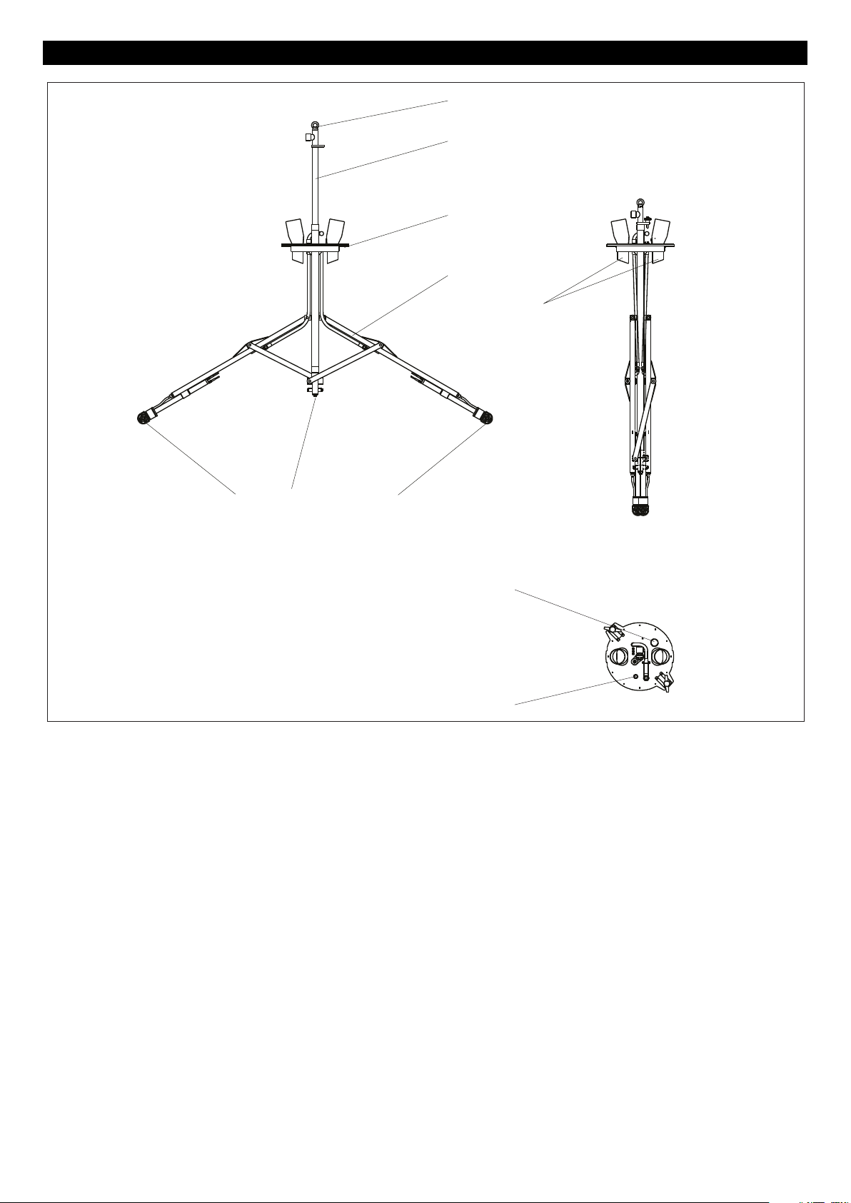
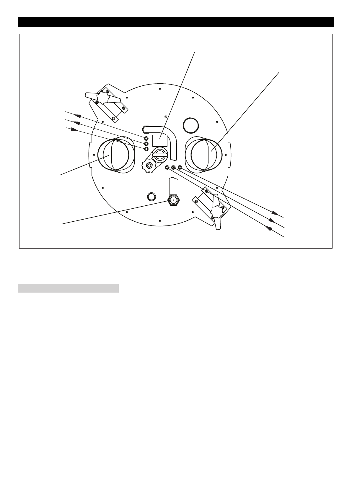
– Die Tank-Reinigungsvorrichtung be-
steht aus Grundplatte (1), Klappgestell
(2), Zugrohr (3) und zwei Reinigungsköpfen (4) mit Druckluftantrieb. Während des Betriebes ist die TankReinigungsvorrichtung mit der Ringschraube (5) an einem Hebezeug befestigt. Das Klappgestell bewegt die
Reinigungsköpfe in die Ein-/Ausfahrstellung (A) oder die Arbeitsstellung (B).
– In der Ein-/Ausfahrstellung ist das Zug-
rohr nach unten geschoben und mit der
Transportsicherung an der Grundplatte
arretiert. Die Reinigungsköpfe sind
nach unten geschwenkt. In dieser Stellung wird die Tank-Reinigungsvorrichtung in Tanks ein- und ausgefahren.
– In Arbeitsstellung ist die Grundplatte
mit den beiden Spannvorrichtungen
dicht auf den Tankdom gespannt.
Durch das Unter-/Überdruckventil (8)
findet der Druckausgleich zwischen Behälter und Umgebung statt. Das Zugrohr wird mit dem Hebezeug bis zur
Markierung nach oben gezogen. Dabei
werden die Reinigungsköpfe in Arbeitsstellung geschwenkt.
BA
9
8
– Über das Zugrohr und die Dampfdüsen
(6) kann Dampf zur Beheizung des
Tanks eingeleitet werden.
– Bei Behältern ohne Boden-Ablassventil
kann durch die Absaugöffnung (9)
Restflüssigkeit mit einer bauseitigen
Saugeinrichtung abgesaugt werden.
– Die Düsen der Reinigungsköpfe drehen
sich um zwei Achsen und erfassen dadurch jede Stelle des Tanks. Der Antrieb erfolgt durch Druckluftmotoren.
– Nach der Reinigung kann über die bei-
den Warmluftanschlüsse (7) Luft zum
Trocknen des Tanks ein- und ausgeleitet werden.
4 DE
- 2
Page 5

Sicherheitshinweise
– Jeweilige nationale Vorschriften des
Gesetzgebers beachten.
– Sicherheitshinweise, die den verwen-
deten Reinigungsmitteln beigestellt
sind (i. d. R. auf dem Verpackungsetikett) beachten.
– Um Gefahren durch falsche Bedienung
zu vermeiden darf die Anlage nur von
Personen bedient werden, die in der
Handhabung unterwiesen sind, ihre Fähigkeiten zum Bedienen nachgewiesen
haben und mit der Benutzung beauftragt sind.
– Die Betriebsanleitung muss jedem Be-
diener zugänglich sein.
Bei Fehlbedienung oder Missbrauch drohen Gefahren für Bediener und andere
Personen durch:
– hohen Druck
– Reinigungsmittel oder verwendete Rei-
nigungsflüssigkeit
– heiße Anlagenteile, wenn heiße Reini-
gungsflüssigkeiten oder Dampf verwendet werden
– Explosionsgefahr
Gefahr
– Quetschgefahr durch Antrieb der Reini-
gungsköpfe. Antrieb der Reinigungsköpfe nur in geschlossenen Behältern
in Betrieb nehmen.
– Quetschgefahr der Hände zwischen
Tank-Reinigungsvorrichtung und Behälter beim Einfahren, deshalb beim
Einfahren Tank-Reinigungsvorrichtung
oberhalb der Grundplatte anfassen und
führen.
– Verletzungsgefahr durch austretenden
Hochdruckstrahl oder Dampf, deshalb
Tank-Reinigungsvorrichtung nur in geschlossenen Behältern in Betrieb setzen, keine beschädigten Behälter
reinigen.
– Verletzungsgefahr durch austretenden
Dampf bei undichten Behältern, deshalb Grundplatte sorgfältig auf dem
Dom des Behälters festspannen und
Verschlussdeckel der Absaugöffnung
vor Inbetriebnahme verschließen.
– Gesundheitsgefahr durch Reststoffe in
Behältern, die gereinigt werden oder
durch die verwendete Reinigungsflüssigkeit. Deshalb vorgeschriebene
Schutzmaßnahmen befolgen.
– Verbrennungsgefahr durch heiße
Schläuche und heißes Gestell bei Betrieb mit heißen Reinigungsflüssigkeiten oder Dampf. Bei Betrieb mit heißen
Reinigungsflüssigkeiten oder Dampf,
Gestell und Zuleitung nicht berühren
und entsprechende Schutzkleidung tragen.
– Verletzungsgefahr durch unbeabsich-
tigten Anlauf bei automatischen Steuerungsabläufen. In diesen Fällen
Bedienpersonal informieren.
– Verletzungsgefahr durch unbeabsich-
tigten Anlauf nach Unterbrechung der
Netzspannung. Bei Störungen Antrieb
der Reinigungsköpfe und Hochdruckpumpe abschalten, Dampfzufuhr
schließen.
– Verletzungsgefahr durch herabstürzen-
de Tank-Reinigungsvorrichtung. Das
Hebezeug muss eine Tragkraft von
mindestens 250 kg besitzen. Der Lasthaken muss eine Sicherung gegen unbeabsichtigtes Aushängen aufweisen.
Explosions- und Brandgefahr bei Verwendung von entsprechenden Reinigungsmitteln und Reststoffen in Behältern.
Informieren Sie sich in diesen Fällen bei
Kärcher, wie entsprechende Reinigungsmittel angewendet werden.
– Tank-Reinigungsvorrichtung elektrisch
erden.
– Feuer- und Explosionsschutzvorschrif-
ten beachten (gegebenenfalls inertisieren, bedampfen etc.).
– Nur die im Kapitel „Reinigungsabläufe“
angegebenen Produkte mit den dort
aufgeführten Reinigungsabläufen reinigen.
Vorsicht
Beschädigungsgefahr an der Tank-Reinigungsvorrichtung und an den Reinigungsköpfen.
– Die Reinigungsköpfe dürfen auf keinen
Fall an der Behälterwand oder Einbauten im Behälter anstoßen, deshalb auf
eine freie Anordnung im Behälter achten.
– Beim Ein- und Ausfahren der Tank-Rei-
nigungsvorrichtung und beim Klappen
in die Arbeitsstellung ist darauf zu achten, dass die Reinigungsköpfe nicht an
den Behälter oder Einbauten im Behälter und im Domhals anstoßen.
– Tank-Reinigungsvorrichtung nur in Ein-
/Ausfahrstellung und mit geschlossener
Transportsicherung in Tanks ein- und
ausfahren.
– Antrieb der Reinigungsköpfe nur in der
Arbeitsstellung des Klappgestells aktivieren.
– Stellung der Spritzdüsen an den Reini-
gungsköpfen nicht durch Drehen von
Hand verstellen. Verstellung von Hand
führt zum Bruch der Überlastsicherung.
Persönliche Schutzausrüstung
Beim Reinigen geräuschverstärkender Teile Gehörschutz zur
Vorbeugung von Gehörschäden tragen.
Je nach Konzentration und Gesundheitsgefahr der verwendeten Reinigungsflüssigkeit, folgende Schutzausrüstung tragen:
– Flüssigkeitsabweisende Schutzklei-
dung
– Schutzbrille oder Gesichtsschutz
– Dichte und beständige Handschuhe
– Dichtes und beständiges Schuhwerk
Zugelassene Bediener
Zugelassene Bediener sind Personen, die
das 18. Lebensjahr vollendet haben und
befähigt sind diese Anlage zu bedienen
(Ausnahmen für Auszubildende, siehe
BGV D15 §6).
Verhalten im Notfall
Separate Hochdruckpumpe ausschal-
ten.
Dampfzuleitung schließen.
Antrieb der Reinigungsköpfe ausschal-
ten, dazu die Druckluftzufuhr schließen.
Zulauf der Reinigungsflüssigkeit schlie-
ßen.
- 3
5DE
Page 6
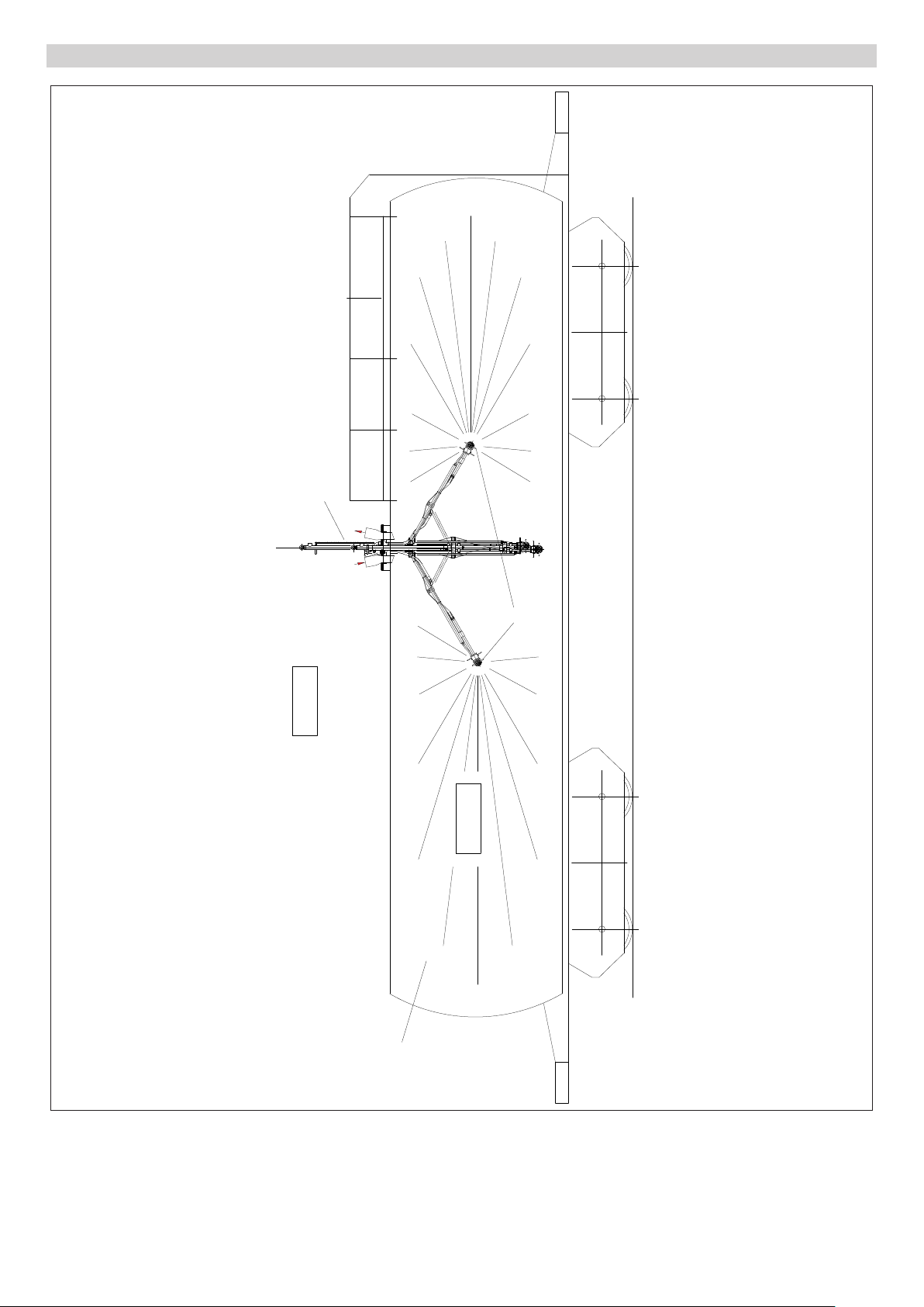
Prinzipskizze Zoneneinteilung
HKF 200 K2
A
B
C
D
A Zone 1
B Rotierender Reinigungskopf
C Zone 0
D Behälter
6 DE
- 4
Page 7

Zoneneinteilung Besondere Bedingungen im Ex-Be-
Explosionsgefährdete Bereiche werden
nach Häufigkeit und Dauer des Auftretens
von gefährlicher explosionsfähiger Atmosphäre in BetrSichV und EN 1127-1 in Zonen eingeteilt.
Die Definition der Zonen liegt in der Verantwortung des Betreibers.
Hinweise zur Zoneneinteilung finden sich in
der BetrSichV, der EN 1127-1, der BGR
104 – Ex-Richtlinie der BG Chemie und in
der EN 60079-10.
– Zone 0
Zone 0 ist ein Bereich, in dem gefährliche explosionsfähige Atmosphäre als
Gemisch aus Luft und brennbaren Gasen, Dämpfen oder Nebeln ständig,
über lange Zeiträume oder häufig vorhanden ist.
– Zone 1
Zone 1 ist ein Bereich, in dem sich bei
Normalbetrieb gelegentlich eine gefährliche explosionsfähige Atmosphäre als
Gemisch aus Luft und brennbaren Gasen, Dämpfen oder Nebeln bilden kann.
– Zone 2
Zone 2 ist ein Bereich, in dem bei Normalbetrieb eine gefährliche explosionsfähige Atmosphäre als Gemisch aus
Luft und brennbaren Gasen, Dämpfen
oder Nebeln normalerweise nicht oder
aber nur kurzzeitig auftritt.
Gefahr
Bei Gefährdung durch Stäube muss zuerst
der zu reinigende Behälter entsprechend
bedampft werden!
reich
1 Der Innenreiniger darf in Zone 0 von
Behältern nur eingesetzt werden, wenn
die Behälter eine Größe von 3 m Durchmesser bei einer üblichen Behälterhöhe oder eine vergleichbare
Behältergröße nicht überschreiten.
2 Der Massengehalt der Reinigungsflüs-
sigkeit an nichtgelösten Feststoffen
darf 1% nicht überschreiten.
3 Der Innenreiniger ist elektrostatisch zu
erden.
4 Die Pumpe für die Reinigungsflüssig-
keit darf nur betrieben werden, wenn
sie mit Flüssigkeit gefüllt ist.
5 Beim Reinigen mit Wasserstrahlen dür-
fen Arbeitsdrücke bis 20 MPa (200 bar)
und Flüssigkeitsdurchsätze von weniger als 18000 l/h (5 l/s) verwendet werden, wenn die Behälter eine Größe von
3 m Durchmesser bei einer üblichen
Behälterhöhe oder eine vergleichbare
Behältergröße nicht überschreiten.
6 Der Druckluftmotor darf nur betrieben
werden, wenn dem Innenreiniger Reinigungsflüssigkeit zugeführt wird.
7 Die Drehzahl des Reinigungskopfes
darf 40 1/min nicht überschreiten.
8 Die Betriebstemperatur der Reini-
gungsflüssigkeit Wasser mit Reinigungsmitteln darf 95 °C nicht
überschreiten.
9 Die Betriebstemperatur der Reini-
gungsflüssigkeiten Laugen und Säuren
darf 20 °C nicht überschreiten.
10 Der Innenreiniger ist nach angemesse-
ner Betriebsdauer auf einwandfreien
Zustand und einwandfreie Funktion zu
prüfen (u.a. Antriebsmotor auf konzentrische Lage zum Stopfbuchsenteil, Lagerbuchsen und antriebsseitige
Dichtung auf Verschleiß bzw. Dichtheit). Gegebenenfalls ist eine Reparatur durchzuführen.
11 Der Innenreiniger darf nur mit solchen
Reinigungsflüssigkeiten betrieben und
in solchen Medien verwendet werden,
gegen deren Einwirkung die Werkstoffe
hinreichend beständig sind.
12 Reinigungsflüssigkeiten, die brennbare
Lösungsmittelanteile enthalten, müssen den Zündgruppen IIA und IIB entsprechen. Lösungsmittel der
Zündgruppe IIC dürfen nicht versprüht
werden.
13 Der Innenreiniger darf nicht dauernd,
sondern nur während der Behälterreinigung in Zone 0 angeordnet sein. Die im
Rahmen der BetrSichV geltenden Betriebsvorschriften sowie weitere nationale Bestimmungen sind einzuhalten.
Es ist zu berücksichtigen, dass die Verbindung Behälter/in den Behälter eingebrachter Innenreiniger nicht
flammendurchschlagsicher ist.
14 Schläuche müssen elektrostatisch leit-
fähig sein (Widerstand R < 1000000
Ohm).
15 Es dürfen nur Reinigungsflüssigkeiten
mit einer Leitfähigkeit G > 1000 pS/m
eingesetzt werden.
16 Alle medienberührten Teile sind an das
Erdungssystem anzuschließen.
Beständigkeit gegen Säuren und
Laugen
Grundsätzlich muss der zu reinigende
Tank vollständig entleert sein.
HKF 200 K2 SO (3.631-054)
Standardausführung
HKF 200 K2 SR (3.631-056)
Säure- und Laugenausführung, buntmetallfrei.
Nur die im Kapitel „Reinigungsabläufe“ angegebenen Produkte mit den dort aufgeführten Reinigungsabläufen reinigen.
Hinweis: Eine Liste der zugelassenen Reinigungsflüssigkeiten befindet sich im Kapitel „Technische Daten“.
- 5
7DE
Page 8

Technische Daten
HKF 200 K2 SO HKF 200 K2 SR
Bestell-Nr. 3.631-054 3.631-056
Hochdruckanschluss
Max. Fördermenge l/h (l/s) 18000 (5) 18000 (5)
Max. Temperatur bei Wasser mit Reinigungsmitteln °C 95 95
Max. Temperatur bei Laugen °C -- 20
Max. Temperatur bei Säuren °C -- 20
Max. Betriebsdruck MPa (bar) 20 (200) 20 (200)
Bauseits vorgeschalteter Wasserfilter μm 100 100
Hochdruckanschluss Zoll G 1 1/2 G 1 1/2
Druckluftanschluss
Druckluft MPa (bar) 0,3-0,6 (3-6) 0,3-0,6 (3-6)
3
Max. Fördermenge Druckluft (bei Normbedingungen) m
Ölnebelschmierung: Ölgehalt (bei Normbedingungen) mm
Funktions-Drehzahl Antrieb 1/min 10-14 10-14
Druckluftanschluss Zoll 2x Rp 1/4 2x Rp 1/4
/h 60 60
3/m3
50 50
Schalldruckpegel (EN 60704-1) dB(A) 83 (ohne Schalldämp-
fer)
83 (ohne Schalldämpfer)
Dampf
Dampftemperatur (max.) °C 191 191
Dampfdurchsatz kg/h 2200 2200
Dampfdruck (max.) MPa (bar) 1,2 (12) 1,2 (12)
Dampfanschluss Zoll Rp 2 Rp 2
Warmluft
Warmlufttemperatur °C 85 85
3
Warmluftdurchsatz m
/h 1000 1000
Warmluftanschluss mm 2x Ø150, außen 2x Ø150, außen
Sonstiges
Behälteröffnung mm Ø560-580 Ø560-580
Gewicht kg ~ 240 ~ 240
Umgebungstemperatur (max.) °C 130 130
Zündschutzart II 1/2 G c T4 II 1/2 G c T4
8 DE
- 6
Page 9
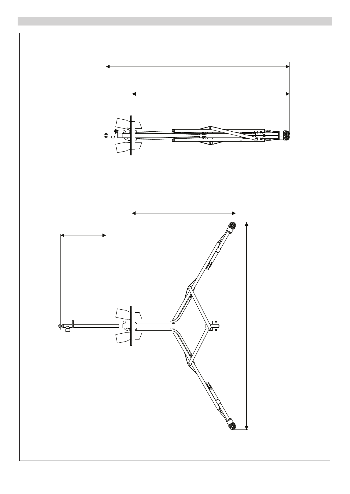
Maßblatt HKF 200 K2
ca. 3160
ca. 2710
780
ca. 1790
ca. 3500
- 7
9DE
Page 10
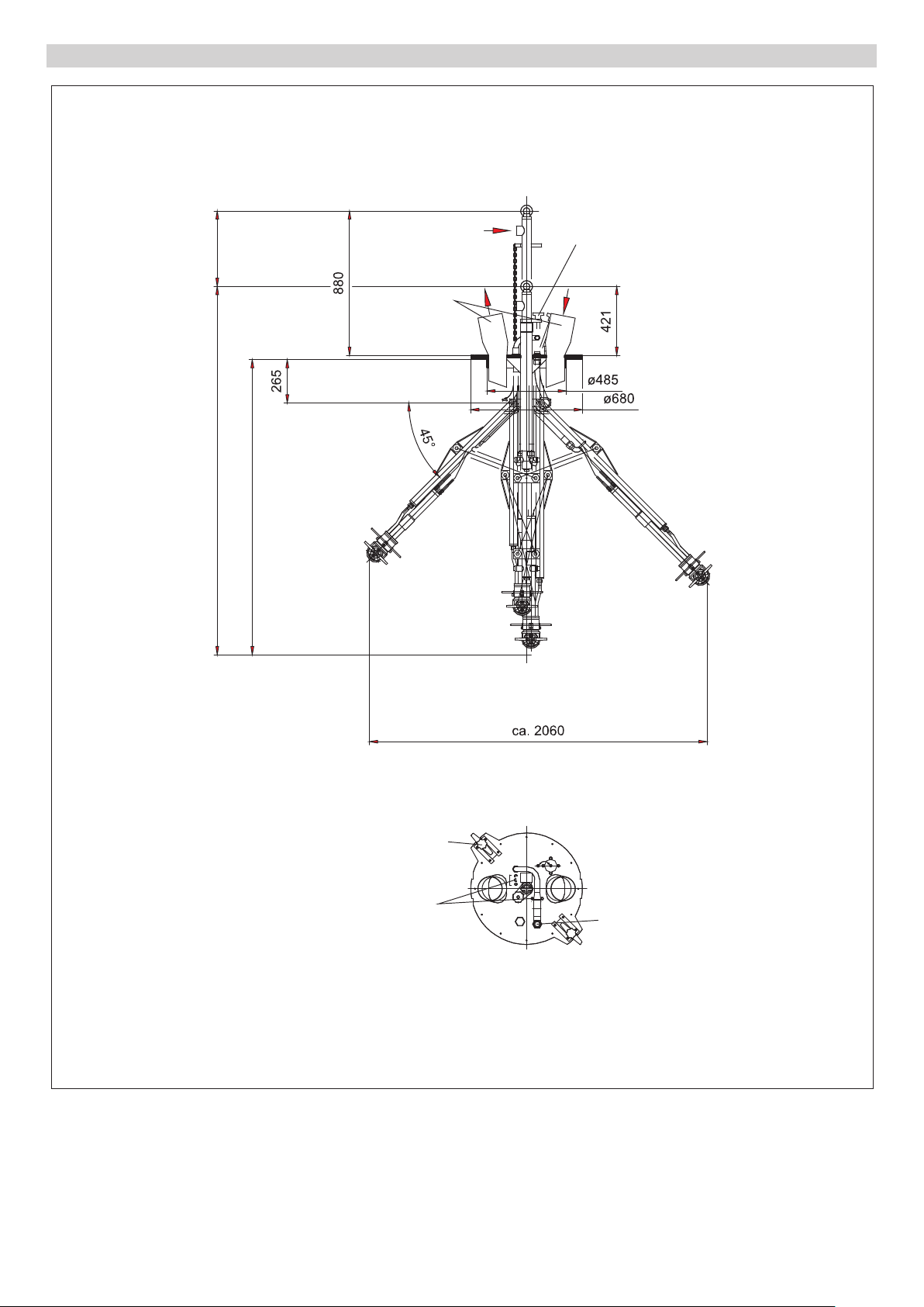
Maßblatt HKF 200 K2 - Kleinste Ausführung
460 (I)
min. 2250 (H)
min. 1810 (G)
C
(2x ø150)
A
(Rp 2")
B
F
E
(Rp 1/4”)
A Dampfanschluss
B Transportsicherung
C Luftanschluss
D Hochdruckanschluss
E 2x 3 Stk. Druckluftanschluss
F 2x Spannvorrichtung (zur Befestigung
an Kesselwagen)
G Einfahrtiefe
H Transportlänge
I Hub
10 DE
D
(R 1 1/2”, DKL 60°)
- 8
Page 11
780 (I)
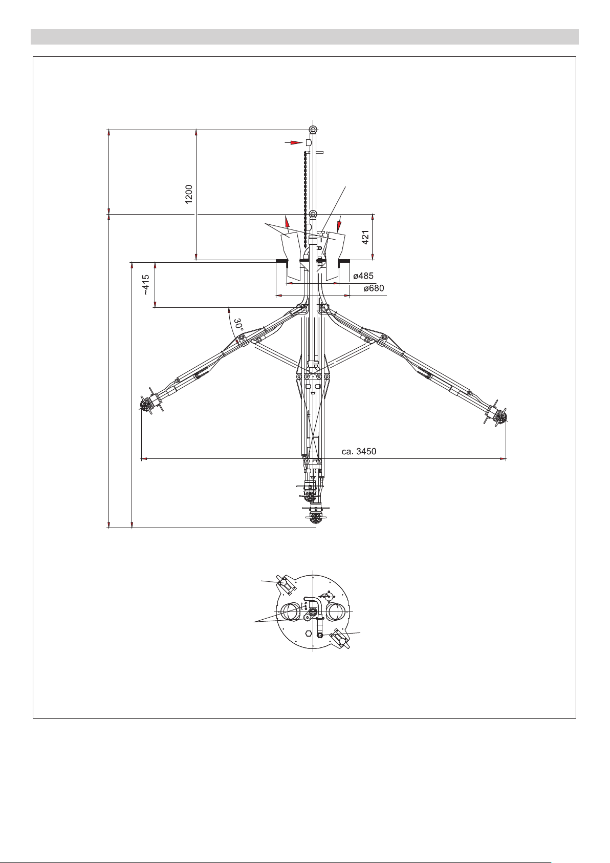
Maßblatt HKF 200 K2 - Beispiel einer mittleren Ausführung
A
(Rp 2")
B
C
(2x ø150)
min. 2900 (H)
min. 2460 (G)
A Dampfanschluss
B Transportsicherung
C Luftanschluss
D Hochdruckanschluss
E 2x 3 Stk. Druckluftanschluss
F 2x Spannvorrichtung (zur Befestigung
an Kesselwagen)
G Einfahrtiefe
F
E
(Rp 1/4”)
H Transportlänge
I Hub
D
(R 1 1/2”, DKL 60°)
- 9
11DE
Page 12
780 (I)
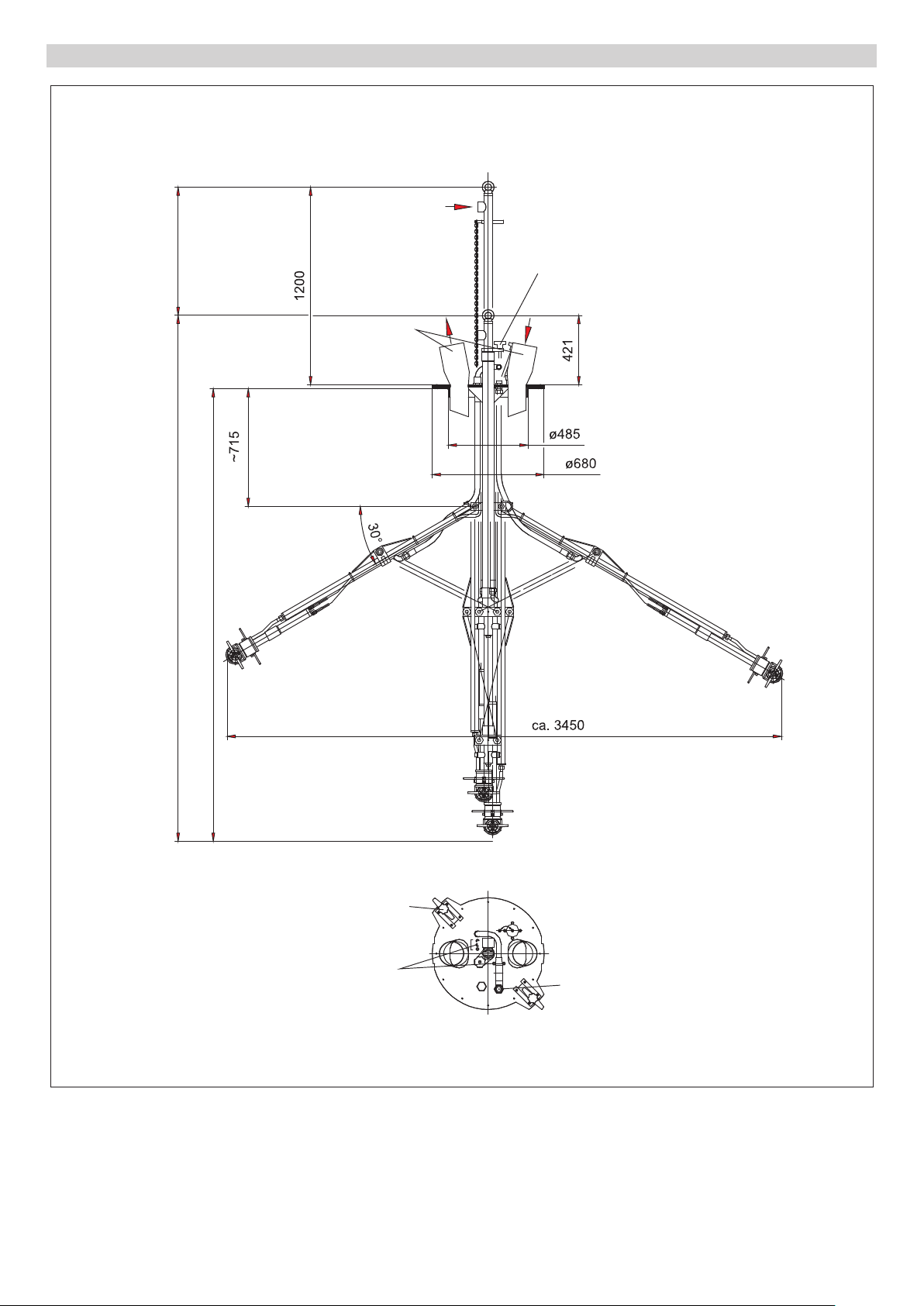
Maßblatt HKF 200 K2 - Größte Ausführung
A
(Rp 2")
B
C
(2x ø150)
min. 3200 (H)
min. 2760 (G)
F
E
(Rp 1/4”)
D
(R 1 1/2”, DKL 60°)
A Dampfanschluss
B Transportsicherung
C Luftanschluss
D Hochdruckanschluss
E 2x 3 Stk. Druckluftanschluss
F 2x Spannvorrichtung (zur Befestigung
an Kesselwagen)
G Einfahrtiefe
H Transportlänge
I Hub
12 DE
- 10
Page 13

Reinigungsflüssigkeiten
Laugen (nur HKF 200 K2 SR)
(max. Temperatur +20 °C)
1 Wasser mit alkalischem Reinigungsmit-
tel (max. 0-2%)
Beispiel: Kärcher-Reinigungsmittel
RM31
2 Natronlaugen max. 10%, ohne Anteile
von Hypochloriten
3 Kaliumhydroxid max. 10%, ohne Antei-
le von Hypochloriten
Säuren (nur HKF 200 K2 SR)
Vorsicht
– Bei Salz- und Schwefelsäure erhöhter
Materialabtrag, deshalb sofort nach
Gebrauch spülen/neutralisieren!
– Bei verunreinigten Säuren verminderte
Beständigkeit!
– Gegebenenfalls bei Kärcher rückfra-
gen!
1 Wasser mit saurem Reinigungsmittel
(max. 0-1%)
Beispiel: Kärcher-Reinigungsmittel
RM25
2 Säuren (max. Temperatur +20 °C)
Salpetersäure max. 10%
Essigsäure max. 10%
Ameisensäure max. 10%
Phosphorsäure max. 10%
Zitronensäure max. 10%
Schwefelsäure max. 0,5%
Salzsäure max. 0,5%
Wasser
1 Wasser
2 Vollentsalztes Wasser
Andere Reinigungsflüssigkeiten
Bei Verwendung anderer Reinigungsflüssigkeiten ist anhand der Werkstoffliste die
Beständigkeit zu überprüfen! Diese Reinigungsflüssigkeiten dürfen nur nach Freigabe von Kärcher eingesetzt werden!
- 11
13DE
Page 14

Werkstoffliste
Pos. Bezeichnung Bestell-Nr. Material Anzahl medienbe-
rührt
1 Schutzteil 4.394-009 (5.000-506) Blech 1.4301, (5.114-077)
Ring 1.4541
2 Schutzteil 4.394-011 1.4301 1 X
3 Ronde 5.005-174 1.4541 3 X
4 Gehäuse 5.060-085 1.4305 1 X
5 Gehäuse 5.060-114 1.4305 1 X
6 Welle 5.100-043 1.4305 1 X
7 Welle 5.100-044 1.4305 1 X
8 Scheibe 5.115-122 Teflon-Bronze 2 X
9 Flansch 5.122-059 1.4305 2 X
10 Flansch 5.122-068 1.4305 1 X
11 Stift 5.314-037 1.4541 2 X
12 Kegelrad 5.354-003 1.4305 1 X
13 Kegelrad 5.354-004 1.4305 1 X
14 Kupplungsteil 5.471-031 1.4305 1 X
15 Ring 5.570-039 CuSn8F55 4 X
16 Zylinder-Schraube M5x12 6.304-011 1.4571 20 X
17 Zylinder-Schraube M5x16 6.304-012 1.4571 10 X
1X
18 Zylinder-Schraube M8x16 6.304-013 1.4571 1 X
19 Zylinder-Schraube M5x30 6.304-112 A4-70 1
20 Sicherungsscheibe 8,4 6.343-125 Nirosta X7 1 X
21 O-Ring 23,47x2,62 6.362-219 EPDM 1 X
22 O-Ring 18x2,5 6.362-431 FPM 1 X
23 O-Ring 17,96x2,62 6.363-154 FPM 1 X
24 Nutring D26xD38 6.365-423 PTFE 4 X
25 6kt.-Schraube M8x16 7.304-538 A4-70 1 X
26 6kt.-Mutter M5 7.311-203 A4-70 2 X
27 Hutmutter M5 7.311-385 A1-50 4 X
28 Dichtring 22 7.362-011 Cu 1 X
29 Verschlussschraube 7.382-251 1.4571 1 X
14 DE
- 12
Page 15
EXH
P2
c
Inbetriebnahme
b
c
1
a
Vor der ersten Inbetriebnahme müssen die
Versorgungsleitungen von den bauseitigen
Versorgungseinrichtungen an die TankReinigungsvorrichtung angeschlossen
werden.
Druckluftanschluss
Wartungseinheit
Vorsicht
Um Schäden am Druckluftantrieb durch
Kondenswasser und mangelnde Schmierung zu vermeiden, Wartungseinheit in
Druckluft-Zuführung einbauen.
Die Wartungseinheit muss wie folgt ausgelegt sein:
– Luftdurchsatz von 60 m
bedingungen)
– Drücke bis 0,6 MPa (aus Sicherheits-
gründen)
– Die Schlauchleitung zwischen War-
tungseinheit und Tank-Reinigungsvorrichtung darf nicht länger als 3 m sein.
Die Wartungseinheit besteht aus:
– Filter
– Wasserabscheider
– Druckregler mit Manometer
– Proportional-Öler
Proportional-Öler mit geeignetem
Schmieröl auffüllen. Ölsorte siehe Betriebsanleitung des Druckluftmotors.
Öler auf 50 mm
ter (mm
Betriebsanleitung des Druckluftmotors.
3/m3
3
) Druckluft einstellen, siehe
3
/h (bei Norm-
Öl pro Normkubikme-
EXH
1
P2
Zuluftschlauch anschließen
– Schlauchgröße für Zuluft jeweils DN 10
Schlauch sauberblasen und an die
Druckluftanschlüsse (P2) anschließen.
Abluft
Die Abluft der Druckluftmotoren tritt an den
Anschlüssen „1“ und „EXH“ aus. Dort können Schalldämpfer oder Abluftschläuche
montiert werden.
Hinweis: Ein Rückstau der Abluft bewirkt
einen unsicheren Lauf des Druckluftmotors. Deshalb ausreichend dimensionierte
Schalldämpfer oder Schläuche verwenden.
- 13
15DE
Page 16
Hochdruckanschluss
Vorsicht
Um eine Beschädigung der Tank-Reinigungsvorrichtung durch zu hohen Druck
oder zu hohe Temperatur zu vermeiden,
Angaben in Kapitel „Technische Daten“
einhalten.
Filter (100 μm) in Zuleitung einbauen,
um ein Verstopfen der Düsen zu verhindern.
Hochdruckschlauch an Hochdruckan-
schluss (a) anschließen.
Dampfanschluss
Zur Beheizung des Tanks vor der Reinigung kann Dampf eingeleitet werden. Dieser Dampf strömt durch das Zugrohr und
tritt durch drei Dampfdüsen in den Tankraum.
Dampfzuleitung am Anschluss für
Dampf (b) anschließen.
Warmluftanschluss
Zur Trocknung des gereinigten Tanks kann
Warmluft eingeblasen werden. Zu diesem
Zweck steht je ein Anschluss (c) zur Zuund Ableitung zur Verfügung. Welcher Anschluss als Zu- und Ableitung verwendet
wird, ist frei wählbar.
Hebezeug
Zum Ein- und Ausfahren sowie zur Betätigung des Klappgestells wird ein Hebezeug
benötigt. Der Lasthaken des Hebezeuges
wird in die Ringschraube am oberen Ende
des Zugrohres eingehängt. Die Rutschkupplung des Hebezeuges muss auf
250 kg eingestellt sein. Dadurch wird eine
mögliche Beschädigung der Tank-Reinigungsvorrichtung verhindert.
Gefahr
Verletzungsgefahr durch herabstürzende
Tank-Reinigungsvorrichtung. Das Hebezeug muss eine Tragkraft von mindestens
250 kg besitzen. Der Lasthaken muss eine
Sicherung gegen unbeabsichtigtes Aushängen aufweisen.
Erdung
Bei brennbaren Reinigungsmitteln oder
Reststoffen muss die Tank-Reinigungsvorrichtung vor der Inbetriebnahme elektrisch
geerdet werden.
Gefahr
Explosions- und Brandgefahr bei Verwendung von entsprechenden Reinigungsmitteln und Reststoffen in Behältern. TankReinigungsvorrichtung elektrisch erden.
Der Betreiber der Anlage ist für die ordnungsgemäße Umsetzung verantwortlich.
Bedienung
Gefahr
Verletzungsgefahr durch austretenden,
eventuell heißen Hochdruck- oder Dampfstrahl.
– Tank-Reinigungsvorrichtung nur in all-
seitig geschlossenen Tanks in Betrieb
nehmen, keine beschädigten Behälter
reinigen, Grundplatte dicht auf dem
Dom des Tanks festspannen.
– Tank-Reinigungsvorrichtung nur bei
ausgeschalteter separater Hochdruckpumpe, abgesperrter Dampfzufuhr und
ausgeschaltetem Eigenantrieb in den
Tank einbringen oder in anderen Tank
überwechseln.
Vorsicht
Beschädigungsgefahr an der Tank-Reinigungsvorrichtung und an den Reinigungsköpfen.
– Die Reinigungsköpfe dürfen auf keinen
Fall an der Behälterwand oder Einbauten im Behälter anstoßen, deshalb auf
eine freie Anordnung im Behälter achten.
– Beim Ein- und Ausfahren der Tank-Rei-
nigungsvorrichtung und beim Klappen
in die Arbeitsstellung ist darauf zu achten, dass die Reinigungsköpfe nicht an
den Behälter oder Einbauten im Behälter und im Domhals anstoßen.
– Tank-Reinigungsvorrichtung nur in Ein-
/Ausfahrstellung und mit geschlossener
Transportsicherung in Tanks ein- und
ausfahren.
– Antrieb der Reinigungsköpfe nur in der
Arbeitsstellung des Klappgestells aktivieren.
– Stellung der Spritzdüsen an den Reini-
gungsköpfen nicht durch Drehen von
Hand verstellen. Verstellung von Hand
führt zum Bruch der Überlastsicherung.
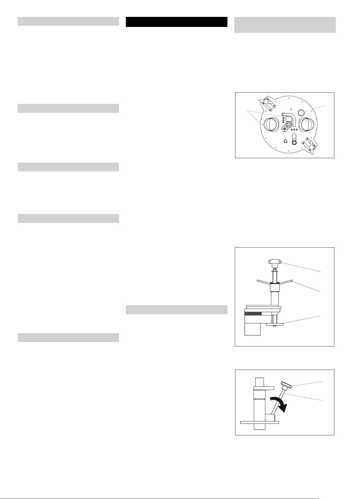
Tankdom vorbereiten
Zur Befestigung der Tank-Reinigungsvorrichtung ist ein Tankdom mit Rand erforderlich. Bei Domen ohne Rand muss ein
Adapter angebracht werden. Für Reststoffe
der Gruppe I und II (siehe Kapitel „Reinigungsabläufe“) wird der Adapter ohne
Kennzeichnung verwendet. Der Adapter für
Reststoffe der Gruppe III trägt die Kennzeichnung III.
Adapter aufsetzen:
Adapter mit der Dichtung nach unten
auf den Dom aufsetzen.
Sterngriff festziehen.
Tank-Reinigungsvorrichtung ein-
fahren
Zu reinigenden Behälter vollständig
entleeren (Bodenablassventil öffnen
oder Restinhalt absaugen).
Tank-Reinigungsvorrichtung in Ein-/
Ausfahrstellung bringen.
Tank-Reinigungsvorrichtung durch Ab-
senken des Hebezeuges in den Tank
einfahren.
10
Grundplatte mittig auf den Dom des
Tanks aufsetzen. Die beiden Nasen
(10) zeigen die Schwenkebene der Reinigungsköpfe an. Die Nasen sollen zur
Tanklängsachse ausgerichtet werden.
Behindert ein Einbauteil im Tank (z.B.
Bodenablassspindel) das Schwenken,
kann die Ausrichtung auch etwas
schräg erfolgen.
Beide Spannvorrichtungen zur Mitte
der Grundplatte schieben, bis die
Scheiben (e) unter den Rand des Domes greifen.
9
f
g
e
Spannvorrichtungen mit dem Sterngriff
(f) vorspannen und mit dem Knebelgriff
(g) festspannen.
h
i
16 DE
Transportsicherung am Sterngriff (h)
öffnen und Spindel (i) zur Seite kippen.
Hinweis: Die an der Tank-Reinigungsvorrichtung angebrachte Kette dient zur Anzeige des Schwenkvorganges. In
- 14
Page 17
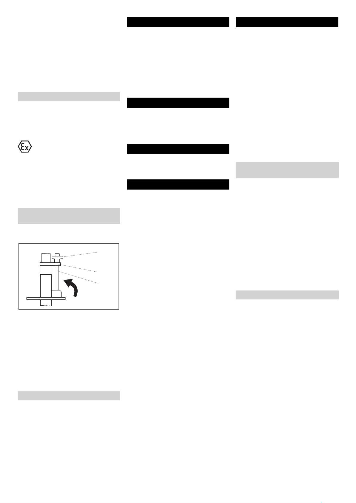
Arbeitsstellung ist diese Kette nahezu gespannt.
Gefahr
Verletzungs- und Beschädigungsgefahr.
Hebezeug nach Erreichen der Arbeitsstellung stoppen.
Zugrohr mit Hebezeug nach oben zie-
hen, bis die Kette nahezu gespannt ist.
Dadurch werden die Reinigungsköpfe
im Tankinneren in die Arbeitsstellung
geschwenkt.
Reinigung
Gefahr
Verletzungsgefahr durch austretenden
Dampf bei undichten Behältern, deshalb
Verschlussdeckel der Absaugöffnung vor
Inbetriebnahme verschließen.
Explosionsgefahr! Der Antrieb der Reinigungsköpfe darf nur bei gleichzeitiger Versorgung mit Reinigungsflüssigkeit
eingeschaltet werden.
Reinigungsprozess durchführen (der
Ablauf des Reinigungsprozesses kann
manuell oder über eine bauseitige
Steuerung erfolgen).
Tank-Reinigungsvorrichtung aus-
fahren
Zugrohr mit dem Hebezeug wieder ab-
senken.
h
k
i
Spindel (i) der Transportsicherung in
die Aussparung der Platte (k) kippen
und Sterngriff (h) festziehen.
Hinweis: Der Sterngriff (h) muss in die Vertiefung der Platte (k) eingreifen. Dadurch
wird das unbeabsichtigte Lösen der Transportsicherung formschlüssig verhindert.
Spannvorrichtungen am Knebelgriff lö-
sen und nach außen zum Rand der
Grundplatte schieben.
Tank-Reinigungsvorrichtung mit Hebe-
zeug aus dem Tank herausheben.
Frostschutz
Die wasserführenden Teile der Anlage sind
vor Frost zu schützen, da sie sonst zerstört
werden können. Soll die Anlage auch bei
Frost betrieben werden, dann muss sie an
einem frostfreien Ort aufgestellt sein.
Außerbetriebnahme
Tank-Reinigungsvorrichtung 30 Sekun-
den ohne Zusatz von Reinigungsmitteln
durchspülen.
Tank-Reinigungsvorrichtung mit einem
Hochdruckreiniger abspritzen.
Hinweis: Dadurch wird ein Verkrusten und
Verkleben und damit ein vorzeitiger Verschleiß der Dichtungen vermieden. Äußerliche Korrosion durch aggressive
Reststoffe wird verhindert.
Stilllegung
Soll eine Anlage während der Frostperiode
stillgelegt werden, dann muss sie vorher
mit einer Frostschutzlösung gespült werden. Frostschutzlösungen schützen im allgemeinen gleichzeitig vor Korrosion.
Lagerung
Vorsicht
Verletzungs- und Beschädigungsgefahr! Gewicht des Gerätes bei Lagerung beachten.
Transport
Vorsicht
Verletzungs- und Beschädigungsgefahr!
Gewicht des Gerätes beim Transport beachten.
Beim Transport in Fahrzeugen Gerät
nach den jeweils gültigen Richtlinien
gegen Rutschen und Kippen sichern.
Pflege und Wartung
Grundlage für eine betriebssichere Anlage
ist eine regelmäßige Wartung.
Verwenden Sie ausschließlich Original-Ersatzteile des Herstellers oder von ihm empfohlene Teile, wie
– Ersatz- und Verschleißteile
– Zubehörteile
– Betriebsstoffe
– Reinigungsmittel
Gefahr
Unfallgefahr bei Arbeiten an der Anlage!
Bei allen Arbeiten:
Hochdruckpumpe am Hauptschalter
spannungsfrei schalten und sichern.
Zulauf der Reinigungsflüssigkeit schlie-
ßen.
Dampfzufuhr schließen.
Antrieb der Reinigungsköpfe ausschal-
ten, dazu die Druckluftzufuhr schließen.
Wer darf Wartungsarbeiten durch-
führen?
Betreiber
Arbeiten mit dem Hinweis „Betreiber“
dürfen nur von unterwiesenen Personen durchgeführt werden, die Hochdruckanlagen sicher bedienen und
warten können.
Fachkräfte
Fachkräfte sind Personen, die durch
ihre berufliche Ausbildung befähigt
sind, Anlagen aufzustellen und in Betrieb zu nehmen.
Kundendienst
Arbeiten mit dem Hinweis „Kundendienst“ dürfen nur von Kärcher Kundendienst-Monteuren durchgeführt
werden.
Wartungsvertrag
Um einen zuverlässigen Betrieb der Anlage
zu gewährleisten, empfehlen wir Ihnen einen Wartungsvertrag abzuschließen. Wenden Sie sich bitte an Ihren zuständigen
Kärcher-Kundendienst.
- 15
17DE
Page 18
Wartungsplan
Zeitpunkt Tätigkeit Durchführung von wem
täglich Wartungseinheit für
Druckluft kontrollieren.
Sichtprüfung der Dichtung
unter der Grundplatte der
Tank-Reinigungsvorrichtung und am Adapter.
wöchentlich oder nach 40
Betriebsstunden
monatlich oder nach 160
Betriebsstunden
alle 600 Betriebsstunden Wartung der Druckluftmo-
Sichtprüfung der Hochdruckschläuche
Transportsicherung überprüfen.
Spannvorrichtungen überprüfen.
Sichtprüfung der Schutzbügel.
Reinigungsköpfe auf
Leichtgängigkeit überprüfen.
Schrauben auf festen Sitz
prüfen.
Gelenkbolzen überprüfen. Gelenkbolzen auf Verschleiß überprüfen. Defekte Teile erset-
Klappgestell überprüfen. Leichtgängigkeit des Klappgestelles überprüfen. Betreiber
toren.
Zahnspiel der Kegelräder
überprüfen.
Gefahr
Gefahr durch Druckluft. Vor Wartungsarbeiten Druckluft
schließen und noch vorhandene Druckluft an der Wartungseinheit ausströmen lassen.
– Wasser im Wasserabscheider ablassen.
– Proportional-Öler mit geeignetem Schmieröl auffüllen. Öl-
sorte siehe Betriebsanleitung des Druckluftmotors.
Gefahr
Verletzungs- und Explosionsgefahr durch nicht intakte Dichtung. Dichtungen auf Einsatzfall, Verschmutzung, Beschädigung und Verschleiß überprüfen, defekte Dichtung
austauschen.
Hochdruckschläuche auf Beschädigungen überprüfen, beschädigte Schläuche austauschen.
Transportsicherung auf Funktion und einwandfreien Zustand
überprüfen.
Spannvorrichtungen zum Befestigen der Grundplatte am Dom
des zu reinigenden Tanks auf Leichtgängigkeit überprüfen.
Schutzbügel der Reinigungsköpfe auf Beschädigung überprüfen. Defekte Schutzbügel richten oder ersetzen.
Tank-Reinigungsvorrichtung außerhalb eines Behälters in Arbeitsstellung bringen, Reinigungsköpfe ohne Reinigungsflüssigkeit in Betrieb nehmen und ordnungsgemäßen Betrieb und
Leichtgängigkeit des Rotationsantriebes überprüfen.
Prüfen, ob alle Schrauben fest angezogen sind. Betreiber
zen.
Wartungsarbeiten nach Betriebsanleitung der Druckluftmotoren durchführen.
Zahnspiel der Kegelräder in den Reinigungsköpfen überprüfen, gegebenenfalls einstellen.
Betreiber
Betreiber
Betreiber
Betreiber
Betreiber
Betreiber
Betreiber
Betreiber
Fachkraft
Kundendienst
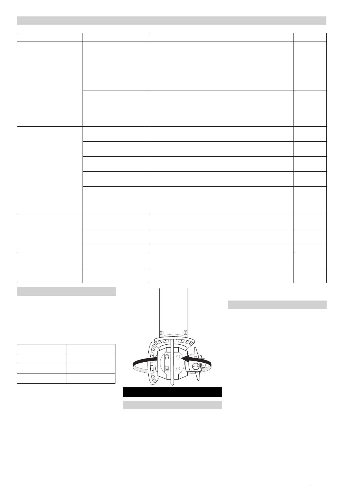
Wartungsarbeiten
Druckluftschläuche austauschen
Beim Austausch der Druckluftschläuche
zwischen Druckluftmotor und Grundplatte
müssen Motor und Anschlüsse in der
Grundplatte nach folgender Tabelle verbunden werden:
Druckluftmotor Grundplatte
11
2P2
EXH EXH
Nach dem Austausch defekter Druckluftschläuche muss die Drehrichtung des Reinigungskopfes kontrolliert werden. Die
richtige Drehrichtung ist nachfolgend angegeben:
Antrieb der Reinigungsköpfe ausschal-
ten, dazu die Druckluftzufuhr schließen.
Wer darf Störungen beseitigen?
Betreiber
Arbeiten mit dem Hinweis „Betreiber“
dürfen nur von unterwiesenen Personen durchgeführt werden, die Hochdruckanlagen sicher bedienen und
warten können.
Kundendienst
Arbeiten mit dem Hinweis „Kundendienst“ dürfen nur von Kärcher Kundendienst-Monteuren durchgeführt
werden.
Hilfe bei Störungen
Störungshinweise
Gefahr
Unfallgefahr bei Arbeiten an der Anlage!
Bei allen Arbeiten:
Hochdruckpumpe am Hauptschalter
spannungsfrei schalten und sichern.
Zulauf der Reinigungsflüssigkeit schlie-
ßen.
Dampfzufuhr schließen.
18 DE
- 16
Page 19

Störungssuche
Störung Mögliche Ursache Behebung von wem
Motor dreht sich nicht Keine Druckluft vorhanden oder
Druck zu gering.
Druckluftzufuhr geknickt. Druckluftschläuche überprüfen. Betreiber
Motor dreht sich, Reinigungskopf dreht sich nicht
Reinigungskopf dreht sich
ruckartig
Ungleichmäßiger Reinigungsstrahl
EG-Konformitätserklärung
Hiermit erklären wir, dass die nachfolgend
bezeichnete Maschine aufgrund ihrer Konzipierung und Bauart sowie in der von uns
in Verkehr gebrachten Ausführung den einschlägigen grundlegenden Sicherheitsund Gesundheitsanforderungen der EGRichtlinien entspricht. Bei einer nicht mit
uns abgestimmten Änderung der Maschine
verliert diese Erklärung ihre Gültigkeit.
Produkt: Innenreiniger
Typ: HKF 200 K2 SO
Typ: HKF 200 K2 SR
Einschlägige EG-Richtlinien
2006/42/EG (+2009/127/EG)
94/9/EG
Angewandte harmonisierte Normen
EN ISO 12100
EN 1127-1: 2007
EN 13463-1: 2009
EN 13463-5: 2003
Angewandte nationale Normen
BGR 132: 2003
Nr. der benannten Stelle:
0123
Prüfbericht-Nr.
70091672
Kennzeichnung
II 1/2 G c T4
Überlastsicherung hat angesprochen.
Mechanischer Defekt an:
– Kupplungsteilen
– Antriebswelle
– Verzahnung
Abgenutzte Anlaufscheiben führen zu erhöhtem Kegelspiel.
Zerstörte Verzahnung der Kegelräder.
Spritzdüsen verstopft. Spritzdüsen reinigen. Betreiber
Spritzdüsen beschädigt. Spritzdüsen austauschen. Betreiber
Alfred Kärcher GmbH & Co. KG
Alfred-Kärcher-Str. 28 - 40
71364 Winnenden (Germany)
Tel.: +49 7195 14-0
Fax: +49 7195 14-2212
Winnenden, 2011/11/01
In jedem Land gelten die von unserer zuständigen Vertriebs-Gesellschaft herausgegebenen Garantiebedingungen. Etwaige
Störungen an dem Gerät beseitigen wir innerhalb der Garantiefrist kostenlos, sofern
ein Material- oder Herstellungsfehler die
Ursache sein sollte.
Druckluftversorgung überprüfen. Betreiber
Beide Befestigungsschrauben des Druckluftmotors entfernen, Druckluftmotor mit Verbindungswelle herausziehen, Verbindungswelle
aus Kupplung ziehen, Sollbruch-Passfeder ersetzen, Verbindungswelle und Motor wieder
montieren.
Teile überprüfen, defekte Teile austauschen. Kundendienst
Anlaufscheiben austauschen. Kundendienst
Kegelräder austauschen. Kundendienst
Betreiber
Garantie
5.957-799
Die Unterzeichnenden handeln im Auftrag
und mit Vollmacht der Geschäftsführung.
CEO
Dokumentationsbevollmächtigter:
S. Reiser
Head of Approbation
- 17
19DE
Page 20

Reinigungsabläufe
Reststoffe Reinigungsflüssigkeiten
Produkt 1. Reinigungsschritt 2. Reinigungsschritt 3. Reinigungsschritt
Produkte der Gruppe I
Motorenöle
– M 100
– M 40
– F 12
– F 5
Heizöl
Kreosot/Teeröl
Paraffinöl
Fettsäure
Phenol
Produkte der Gruppe II
Aceton
Methylstyrol
Diesel
Benzin
Wasserdampf
max. 1,2 MPa (12 bar), 191 °C
Wasserdampf
max. 1,2 MPa (12 bar), 191 °C
Entflammbarkeit und Viskosi-
Heizöl „EL“
Wasser
tät nach DIN 51603
75/85 °C
25/40 °C
Kaltwasser
--
max. 20 °C
Produkte der Gruppe III
Ammoniak (Lösung 10-15%)
Soda, calciniert (Lösung 42%)
Salzsäure (Lösung 35%)
Salpetersäure (Lösung 72%)
Schwefelsäure (Lösung 92%)
– Vor Reinigungsbeginn muss der Tan-
kinnenraum vollständig entleert werden.
– Der Tankinnenraum darf bei Reini-
gungsbeginn maximal 25 Liter Reststoffe der Gruppe II und III sowie der
flüssigen Produkte der Gruppe I enthalten.
– Der Dampf hat zusätzlich zur Reini-
gungsfunktion gleichzeitig eine Schutzfunktion (Inertisierung) bei der
Reinigung von entflammbaren Produkten. Insbesondere bei Produkten der
Gruppe II und Behältnissen über 3 m
Durchmesser ist gegebenenfalls entsprechend den örtlichen gesetzlichen
Vorschriften eine Bedampfung als
Schutzmaßnahme durchzuführen.
Kaltwasser
-- --
max. 20 °C
20 DE
- 18
Page 21

Please read and comply with
English
or to the initial operation of your appliance
and store them for later use or subsequent
owners.
– Before first start-up it is definitely nec-
essary to read the operating instructions and safety indications Nr. 5.951949!
– In case of transport damage inform ven-
dor immediately
these original instructions pri-
Contents
Environmental protection . . EN . . 1
Symbols in the operating in-
structions . . . . . . . . . . . . . . EN . . 1
Proper use . . . . . . . . . . . . . EN . . 1
Function . . . . . . . . . . . . . . . EN . . 2
Safety instructions . . . . . . . EN . . 3
Technical specifications . . . EN . . 6
Start up . . . . . . . . . . . . . . . . EN . 13
Operation . . . . . . . . . . . . . . EN . 14
Shutting down . . . . . . . . . . . EN . 15
Shutdown . . . . . . . . . . . . . . EN . 15
Storage . . . . . . . . . . . . . . . . EN . 15
Transport . . . . . . . . . . . . . . EN . 15
Maintenance and care . . . . EN . 15
Troubleshooting . . . . . . . . . EN . 16
EC Declaration of Conformity EN . 17
Warranty . . . . . . . . . . . . . . . EN . 17
Cleaning sequences . . . . . . EN . 18
Environmental protection
The packaging material can be
recycled. Please do not throw
the packaging material into
household waste; please send
it for recycling.
Old appliances contain valuable materials that can be recycled; these should be sent for
recycling. Batteries, oil, and
similar substances must not
enter the environment. Please
dispose of your old appliances
using appropriate collection
systems.
Notes about the ingredients (REACH)
You will find current information about the
ingredients at:
www.kaercher.com/REACH
Symbols in the operating in-
structions
Danger
Immediate danger that can cause severe
injury or even death.
몇 Warning
Possible hazardous situation that could
lead to severe injury or even death.
Caution
Possible hazardous situation that could
lead to mild injury to persons or damage to
property.
Proper use
– The tank cleaning device HKF 200 K2 is
a spray unit to clean tank vehicles.
– The cleaning heads are lowered into
the completely emptied tank from
above. After fastening the base plate to
the dome of the tank, the two cleaning
heads are swivelled into their working
position via a mechanical unit and they
clean the interior walls of the tank with
high pressure liquid jets. The tank can
be heated from the inside prior to the
cleaning process by adding water vapour (saturated steam). Warm air can
be channeled into the tank for drying
purposes.
– Compressed air, high pressure, steam,
warm air are created by separate devices and are connected to the tank cleaning device via supply lines. The
operator is responsible for the safety of
the entire system.
– The tank cleaning device must only be
present in the tank during the cleaning
process. The drive of the cleaning
heads must only be switched on while
the cleaning liquid is supplied at the
same time.
Note: Only the detergents listed in Chapter
"Cleaning processes" must be used at the
indicated temperatures. Here, only use the
allocated detergents in Chapter "Cleaning
processes" for the listed residual materials.
Operation outside closed containers and
with higher pressure and temperatures
than those listed in the "Specifications" is
prohibited.
Please do not allow cleaning liquids to
enter the environment. Protect the
ground and dispose of used oil in an environmentally-clean manner.
Please do not let mineral oil contaminated waste water reach soil, water or the
sewage system.
- 1
21EN
Page 22

Function
5
3
1
2
7
446
– The tank cleaning device consists of a
base plate (1), folding rack (2), draw
pipe (3) and two cleaning heads (4) with
compressed air drive. The tank cleaning device is fastened to a lift unit with
the ring screw (5) during operation. The
folding rack moves the cleaning heads
into the extended/rectracted position
(A) or into the working position (B).
– In the extended/retracted position, the
draw pipe must be slid down and fastened to the base plate by means of the
transport lock. The cleaning heads are
tilted downwards. In this position, the
tank cleaning device is extended into
the tanks and extracted from them.
– In the working position, the base plate is
tensioned tightly onto the tank dome by
means of the tensioning units. The vacuum/high pressure valve (8) equalizes
the pressure between the container and
the atmosphere. The draw pipe is
pulled up to the mark toward the top by
means of the lifting unit. Here, the
cleaning heads are swivelled into the
working position.
BA
9
8
– Steam to heat the tank can be drawn in
via the draw pipe and the steam nozzles (6).
– For containers without floor drain
valves, the remaining liquid can be suctioned off through the suction opening
(9) by means of a site-supplied suction
device.
– The nozzles on the cleaning heads turn
around two axles and therefore touch
every place in the container. They are
driven by compressed air motors.
– After the cleaning, air can be chan-
nelled in and out of the tank to dry it via
the two warm air connections (7).
22 EN
- 2
Page 23

Safety instructions
– Please follow the national rules and
regulations of the respective country.
– Please follow the safety instructions
which are attached to the used detergents (normally on the packing label).
– In order to avoid improper operation,
the system may only be used by persons who have been instructed in handling the system or have proven
qualification and expertise in operating
the system or have been explicitly assigned the task of handling the system.
– The operating instructions must be ac-
cessible for every user.
Wrong operation or misuse are hazardous
to the operator and other persons on account of:
– high pressure
– Cleaning agents or used cleaning liquid
– hot system parts, if hot cleaning liquid
or steam is used
– Danger of explosion
Danger
–
Danger of crushing by the drive of the
cleaning heads. Only use the drive of
the cleaning heads in closed containers.
– Risk of crushing hands between tank
cleaning device and container during
the retraction phase; therefore hold the
tank cleaning device above the baseplate to guide it during the retraction.
– Danger of injury by high pressure jet or
steam - therefore only use tank cleaning device inside closed containers; do
not clean damaged containers.
– Risk of injury by escaping steam with
leaking containers. Therefore, clamp
the baseplate carefully on the dome of
the container and close the lid of the
suction opening prior to operation.
– Health hazards posed by residue in
containers that are cleaned or by the
cleaning liquid used. Therefore, the listed protective measures must be adhered to.
– Risk of burns by hot hoses and hot rack
when using hot cleaning liquids or
steam. When operating with hot cleaning liquids or steam, do not touch the
rack and supply lines and wear protective clothing.
– Risk of injury if the machine is started
inadvertently with automatic control
runs. In those cases, inform the operating personnel.
– Risk of injury by inadvertent machine
startup after the system power has
been interrupted. In case of malfunctions, switch off the drive of the cleaning
heads as well as the high pressure
pump; shut off the steam supply.
– Risk of injury on account of a drop of the
tank cleaning device. The lifting unit
must have a load capacity of at least
250 kg. The load hook must have a security system against inadvertent unhooking.
Risk of explosion and fire when using
cleaning agents and residue in the containers. Please contact Kärcher in such cases
to find out, how the respective cleaning
agents should be used.
– Ground the tank cleaning device eletri-
cally.
– Observe the fire and explosion protec-
tion regulations (inertiase, steam, etc. if
necessary).
– Only the products listed in Chapter
"Cleaning processes" must be cleaned
using the cleaning sequences listed
there.
Caution
Risk of damage on the tank cleaning device
and on the cleaning heads.
– The cleaning heads must never touch
the container wall or the items inside
the container. Please make sure these
are arranged with sufficient clearance
between them.
– When retracting and extending the tank
cleaning device and when folding it into
its working position, make sure that the
cleaning heads do not hit the container
or the items inside the container and inside the dome neck.
– Only extend and retract the tank clean-
ing device into and from the tank while
in extend/extract position and with the
transport safety device closed.
– Only activate the drive of the cleaning
heads while the folding rack is in its
working position.
– Do not manually adjust the position of
the spray nozzles on the cleaning
heads by turning them. A manual adjustment causes the breakage of the
overload fuse.
Personal safety gear
Wear ear plugs to protect
your ears against hearing
loss while cleaning parts
that produce high sound
levels.
Depending on the concentration and health
risk of the used cleaning liquid, wear the following protective gear:
– Liquid resistant protective clothing
– Protective glasses or face shield
– Dense and durable gloves
– Dense and protective shoes
Approved operators
Approved operators are persons who are at
least 18 years old and are able to operate
this system (exceptions: apprentices, see
BGV D15 §6).
Behaviour in emergency situations
Switch off the separate high pressure
pump.
Close the steam supply.
Switch off the drive of the cleaning
heads and shut off the compressed air
supply.
Shut off the cleaning liquid supply.
- 3
23EN
Page 24

Basic sketch - zone layout
HKF 200 K2
A
B
C
D
A Zone 1
B Rotating cleaning head
C Zone 0
D Container
24 EN
- 4
Page 25

Zone layout Special conditions in the Ex area Durability against acids and brines
Areas that bear the risk of explosion are divided into zones, according to the frequency and duration of explosion-risk
atmosphere in BetrSichV and EN 1127-1.
The definition of the zones lies in the responsibility of the operator.
Tips for zoning are included in the BetrSichV, EN 1127-1, BGR 104 – Ex-guideline of BG Chemie and in the EN 60079-10.
– Zone 0
Zone 0 is an area where dangerous explosion-risk atmosphere is present as a
mixture of air and flammable gases, vapors or mists at all times, across long
time periods or frequently.
– Zone 1
Zone 1 is an area where (during normal
operation) dangerous explosion-risk atmosphere is present as a mixture of air
and flammable gases, vapors or mists
from time to time.
– Zone 2
Zone 2 is an area where (during normal
operation) dangerous explosion-risk atmosphere as a mixture of air and flammable gases, vapors or mists is not
normally present and if present, only for
a short time.
Danger
If there is a risk of dust, the container to be
cleaned must be steamed accordingly!
1 The interior cleaner must only be used
in Zone 0 if the containers are at least 3
m in diameter with the usual container
height or do not exceed a comparable
container size.
2 The mass content of non-diluted solid
substances in the cleaning liquid must
not exceed 1%.
3 The interior cleaner must be ground
electro-statically.
4 The pump for the cleaning liquid must
only be operated while it is filled with fluid.
5 When cleaning by water streams, you
must use working pressures up to 20
MPa (200 bar) and liquid throughputs of
less than 18,000 l/h (5 l/s), if the containers do not exceed a diameter of 3 m
with a typical container height or a comparable container size.
6 The compressed air motor must only be
operated once the interior cleaner has
been filled with cleaning liquid.
7 The speed of the cleaning head must
not exceed 40 rpm.
8 The operating temperature of the clean-
ing liquid water with cleaning agents
must not must not exceed 95 °C.
9 The operating temperature of the clean-
ing liquids, brines and acids must not
must not exceed 20 °C.
10 The interior cleaner must be checked
for flawless condition and smooth function after a certain operating time has
passed (incl. drive motor for its concentrical position in relation to the gland,
bearing bushings and drive-side seal
for wear and tear and leakage). If applicable, a repair needs to be conducted.
11 The interior cleaner must only be used
with cleaning liquids and in such media,
whose affect on the materials is not
damaging.
12 Cleaning liquids that contain flammable
solvent particles, must comply with the
ignition groups IIA and IIB. Solvents of
the ignition group IIC must not be
sprayed.
13 The interior cleaner must not be con-
stantly located in Zone 0, but only during the actual container cleaning. The
operating guidelines as per BetrSichV
as well as other national guidelines
must be adhered to. Take into consideration, that the mixture of the container/
interior cleaner brought into the container is not resistant to breakdown
from flames.
14 Hoses must be conductive (electrostat-
ically) (resistance R < 1000000 Ohm).
15 Only cleaning agents with a conductivi-
ty G > 1000 pS/m may be used.
16 All parts that touch media must be con-
nected to the grounding system.
Basically, the tank to be cleaned must be
completely emptied.
HKF 200 K2 SO (3.631-054)
Standard model
HKF 200 K2 SR (3.631-056)
Acid and brine model, free of coloured
metals.
Only the products listed in Chapter "Cleaning processes" must be cleaned using the
cleaning sequences listed there.
Note: The chapter "Specifications" contains a list of the permitted cleaning liquids.
- 5
25EN
Page 26

Technical specifications
HKF 200 K2 SO HKF 200 K2 SR
Order No. 3.631-054 3.631-056
High pressure connection
Max. flow rate l/h (l/s) 18000 (5) 18000 (5)
Max. temperature with water with cleaning agents °C 95 95
Max. temperature for brines °C -- 20
Max. temperature with acids °C -- 20
Max. operating pressure MPa (bar) 20 (200) 20 (200)
Site-supplied preswitched water filter μm 100 100
High pressure connection Inch G 1 1/2 G 1 1/2
Compressed air connection
Compressed air MPa (bar) 0,3-0,6 (3-6) 0,3-0,6 (3-6)
3
Max. flow rate of compressed air (during standard conditions) m
Oil mist lubrication: Oil content (with standard conditions) mm
Functional speed - drive 1/min 10-14 10-14
Compressed air connection Inch 2x Rp 1/4 2x Rp 1/4
/h 60 60
3/m3
50 50
Sound pressure level (EN 60704-1) dB(A) 83 (without silencer) 83 (without silencer)
Steam
Steam temperature (max.) °C 191 191
Steam throughput kg/h 2200 2200
Steam pressure (max.) MPa (bar) 1,2 (12) 1,2 (12)
Steam connection Inch Rp 2 Rp 2
Warm air
Warm air temperature °C 85 85
3
Warm air throughput m
/h 1000 1000
Warm air connection mm 2x Ø150, exterior 2x Ø150, exterior
Other
Container opening mm Ø560-580 Ø560-580
Weight kg ~ 240 ~ 240
Max. ambient temperature °C 130 130
Ignition protection class II 1/2 G c T4 II 1/2 G c T4
26 EN
- 6
Page 27

Measuring sheet HKF 200 K2
ca. 3160
ca. 2710
780
ca. 1790
ca. 3500
- 7
27EN
Page 28

Measuring sheet HKF 200 K2 - smallest model
460 (I)
min. 2250 (H)
min. 1810 (G)
C
(2x ø150)
A
(Rp 2")
B
F
E
(Rp 1/4”)
A Steam connection
B Transport lock
C Air connection
D High pressure connection
E 2x 3 ea. Compressed air connection
F 2x clamping device (for affixing to the
boiler cart)
G Insertion depth
H Transport length
I Hub
28 EN
D
(R 1 1/2”, DKL 60°)
- 8
Page 29

780 (I)
Measuring sheet HKF 200 K2 - example for a medium model
A
(Rp 2")
B
C
(2x ø150)
min. 2900 (H)
min. 2460 (G)
A Steam connection
B Transport lock
C Air connection
D High pressure connection
E 2x 3 ea. Compressed air connection
F 2x clamping device (for affixing to the
boiler cart)
G Insertion depth
F
E
(Rp 1/4”)
H Transport length
I Hub
D
(R 1 1/2”, DKL 60°)
- 9
29EN
Page 30

780 (I)
Measuring sheet HKF 200 K2 - largest model
A
(Rp 2")
B
C
(2x ø150)
min. 3200 (H)
min. 2760 (G)
F
E
(Rp 1/4”)
D
(R 1 1/2”, DKL 60°)
A Steam connection
B Transport lock
C Air connection
D High pressure connection
E 2x 3 ea. Compressed air connection
F 2x clamping device (for affixing to the
boiler cart)
G Insertion depth
H Transport length
I Hub
30 EN
- 10
Page 31

Cleaning liquids
Brines (HKF 200 K2 SR only)
(max. temperature +20 °C)
1 Water with alkaline cleaning agents
(max. 0-2%)
Example: Kärcher cleaning agents
RM31
2 Caustic soda max. 10%, without hy-
pochlorite particles
3 Potassium hydroxide max. 10%, with-
out hypochlorite particles
Acids (HKF 200 K2 SR only)
Caution
– The material will be worn off faster
when using hydrochloric or sulfuric acids; therefore it must be rinsed/neutralised immediately!
– Contaminated acids will decrease the
resilience!
– Enquire with Kärcher if needed!
1 Water with acid cleaning agents (max.
0-1%)
Example: Kärcher cleaning agents
RM25
2 Acids (max. temperature +20 °C)
Nitric acid max. 10%.
Acetic acid max. 10%.
Formic acid max. 10%.
Phosphoric acid max. 10%.
Citric acid max. 10%.
Sulfuric acid max. 0.5%.
Hydrochloric acid max. 0.5%.
Water
1 Water
2 Fully desalted water
Other cleaning liquids
If other cleaning liquids are used, their resilience must be checked by means of the
materials list! These cleaning liquids can
only be used after being released by Kärcher!
- 11
31EN
Page 32

Materials list
Item: Description Order No. Material Quanti-tytouching
media
1 Protective part 4.394-009 (5.000-506) sheet metal 1.4301, (5.114-
077) ring 1.4541
2 Protective part 4.394-011 1.4301 1 X
3 Circular blank 5.005-174 1.4541 3 X
4 Casing 5.060-085 1.4305 1 X
5 Casing 5.060-114 1.4305 1 X
6 Shaft 5.100-043 1.4305 1 X
7 Shaft 5.100-044 1.4305 1 X
8 Disc 5.115-122 Teflon bronze 2 X
9 Flange 5.122-059 1.4305 2 X
10 Flange 5.122-068 1.4305 1 X
11 Pin 5.314-037 1.4541 2 X
12 Bevel wheel 5.354-003 1.4305 1 X
13 Bevel wheel 5.354-004 1.4305 1 X
14 Coupling unit 5.471-031 1.4305 1 X
15 Ring 5.570-039 CuSn8F55 4 X
16 Cylinder screw M5x12 6.304-011 1.4571 20 X
17 Cylinder screw M5x16 6.304-012 1.4571 10 X
1X
18 Cylinder screw M8x16 6.304-013 1.4571 1 X
19 Cylinder screw M5x30 6.304-112 A4-70 1
20 Safety disc 8,4 6.343-125 Nirosta X7 1 X
21 O-Ring 23.47x2.62 6.362-219 EPDM 1 X
22 O-Ring 18x2.5 6.362-431 FPM 1 X
23 O-Ring 17.96x2.62 6.363-154 FPM 1 X
24 Grooved ring D26xD38 6.365-423 PTFE 4 X
25 Hex screw M8x16 7.304-538 A4-70 1 X
26 Hex nut M5 7.311-203 A4-70 2 X
27 Domed cap nut M5 7.311-385 A1-50 4 X
28 Seal ring 22 7.362-011 Cu 1 X
29 Screwed sealing plug 7.382-251 1.4571 1 X
32 EN
- 12
Page 33

EXH
P2
c
Start up
b
c
1
a
Prior to the initial startup, the supply lines
from the site-supplied supply units must be
connected to the tank cleaning device.
Compressed air connection
Maintenance unit
Caution
In order to avoid damage to the compressed air drive by condensation wear
and lack of lubrication, install a maintenance unit into the compressed air supply.
This maintenance unit must be laid out as
follows:
– Air throughput of 60 m
conditions)
– Pressures of up to 0.6 MPa (for safety
reasons)
– The hose line between the mainte-
nance units and the tank cleaning device must not be longer than 3 m.
The maintenance unit consists of:
– Filter
– Water separator
– Pressure regulator with manometer
– Proportional oiler
Fill the proportional oiler with a suitable
lubricant. Oil type - see operating instructions of the compressed air motor.
Set the oiler to 50 mm
cubic meter (mm
see operating instructions of the compressed air motor.
3
/h (with standard
3
oil per standard
3/m3
) compressed air,
EXH
1
P2
Connect supply air hose
– Hose size for supply air as per DIN 10
Blow the hose clean and connect it to
the compressed air connections (P2).
Exhaust air
The exhaust air of the compressed air motors exits at the connections "1" and "EXH".
Here, you can connect mufflers or exhaust
hoses.
Note: A reflux of the exhaust air causes an
unsafe run of the compressed air motor.
Therefore, you must use large enough mufflers or hoses.
- 13
33EN
Page 34

High pressure connection
Caution
In order to avoid damage to the tank cleaning device by excessive pressure or too
high of a temperature, adher to the instructions in the Chapter "Specifications".
Install a filter (100 μm) into the supply
line to prevent clogging of the nozzles.
Connect the high pressure hose to the
high pressure connection (a).
Steam connection
To heat the tank prior to cleaning, steam
can be channelled in. This steam streams
through the draw pipe and enters the tank
area through three steam nozzles.
Connect the steam supply line at the
steam connection (b).
Warm air connection
To dry the cleaned tank, you can blow in
warm air. For this purpose, there is the connection (c) for the supply and exhaust flow.
You can select which connection you would
like to use for supply/exhaust.
Lifting unit
To extend/retract as well as for the actuation of the folding rack, you will need a lifting unit. The load hook of the lifting unit is
hooked into the ring screw at the top end of
the draw pipe. The slip clutch of the lifting
unit must be set to 250 kg. This will prevent
possible damage to the tank cleaning the
device.
Danger
Risk of injury on account of a drop of the
tank cleaning device. The lifting unit must
have a load capacity of at least 250 kg. The
load hook must have a security system
against inadvertent unhooking.
Earthing
For flammable detergents or residual materials, the tank cleaning device must be
electrically grounded prior to startup.
Danger
Risk of explosion and fire when using
cleaning agents and residue in the containers. Ground the tank cleaning device eletrically. The operator of the system is
responsible for the proper implementation.
Operation
Danger
Risk of injury on account of the possibly hot
high pressure or steam jet.
– Only take the tank cleaning device in
completely closed tanks, do not clean
damaged containers, clamp the baseplate down close to the dome of the
tank.
– Only insert the tank cleaning device into
the tank or switch it into another tank
while the separate high pressure pump
and internal drive as well as the steam
inflow are turned off.
Caution
Risk of damage on the tank cleaning device
and on the cleaning heads.
– The cleaning heads must never touch
the container wall or the items inside
the container. Please make sure these
are arranged with sufficient clearance
between them.
– When retracting and extending the tank
cleaning device and when folding it into
its working position, make sure that the
cleaning heads do not hit the container
or the items inside the container and inside the dome neck.
– Only extend and retract the tank clean-
ing device into and from the tank while
in extend/extract position and with the
transport safety device closed.
– Only activate the drive of the cleaning
heads while the folding rack is in its
working position.
– Do not manually adjust the position of
the spray nozzles on the cleaning
heads by turning them. A manual adjustment causes the breakage of the
overload fuse.
Preparing the tank dome
To fasten the tank cleaning device, you will
need a tank dome with a ledge. For domes
without a ledge, you must install an adapter. For residual materials of group I and II
(see Chapter "Cleaning processes"), the
adapter without marking is used. The
adapter for residual materials of Group III is
marked with a III.
Installing the adapter:
Install the adapter onto the dome with
the seal facing down.
Tighten the star handle.
Retract the tank cleaning device
Completely empty the container to be
cleaned (open the floor drain valve or
suction off the remaining contents).
Bring the tank cleaning device into its
extend/retract position.
Retract the tank cleaning device into
the tank by lowering the lifting unit.
10
Center the baseplate on the dome of
the tank. The two noses (10) show the
swivelling plane of cleaning heads. The
noses should be aligned with the longitudinal axis of the tank. If an installed
part in the tank (such as a floor drain
spindle) obstructs the swivelling movement, the alignment can be slightly
askew.
Slide both tensioning units into the cen-
tre of the baseplate until the discs (e)
are located underneath the ledge of the
dome.
9
f
g
e
Pretension the tensioning units with the
star handle (f) and clamp them tight with
the T-handle (g).
h
i
34 EN
Open the transport safety device on the
star handle (h) and tilt the spindle (i) to
the side.
Note: The chain attached to the tank cleaning device is used to show the swivelling
motion. In the working position, this chain is
almost stretched tight.
- 14
Page 35

Danger
Risk of injury and damage. Stop the lifting
unit after the working position has been
reached.
Pull the draw pipe upwards with the lift-
ing unit until the chain is almost completely tensioned. Now, the cleaning
heads are swivelled into the working
position on the inside of the tank.
Cleaning
Danger
Risk of injury by escaping steam with leaking containers. Therefore, close the lid of
the suction opening prior to operation.
Risk of explosion! The drive of the cleaning
heads must only be switched on while the
cleaning liquid is supplied at the same time.
Perform the cleaning process (the se-
quence of the cleaning process can
take place manually or via a site-supplied controller).
Extend the tank cleaning device
Lower the draw pipe by means of the
lifting unit.
h
k
i
Tilt the spindle (i) of the transport safety
device into the recess fo the plate (k)
and tighten the star handle (h).
Note: The star handle (h) must be inserted
into the recess of the plate (k). This will prevent inadvertent loosening of the transport
safety device.
Loosen the tensioning units on the T-
handle and slide them toward the outside to the edge of the baseplate.
Lift the tank cleaning device out of the
tank using the lifting unit.
Frost protection
Protect the water-carrying parts of the plant
against frost because they can get totally
damaged. If the system is to be used during
frost conditions, it must be erected in a
frost-free location.
Shutting down
Rinse the tank cleaning device for 30
seconds without adding detergents.
Spray the tank cleaning device with a
high pressure cleaner.
Note: This will avoid crusting and adhesion
and thus a premature wear of the seals.
This will prevent exterior corrosion by aggressive residual materials.
Shutdown
If a system is to be shut down during frost
conditions, it must be rinsed with a frost
protection solution. Frost protection solutions generally protect from corrosion at the
same time.
Storage
Caution
Risk of injury and damage! Note the weight
of the appliance in case of storage.
Transport
Caution
Risk of injury and damage! Observe the
weight of the appliance when you transport
it.
When transporting in vehicles, secure
the appliance according to the guidelines from slipping and tipping over.
Maintenance and care
The basis for a safe operational plant is
regular maintenance.
Use only original parts of the manufacturer
or part suggessted by him, such as
– replacement and wear parts
– Accessory parts
– Fuel
– Detergent
Danger
Risk of accident while working on the unit!
During all tasks:
Remove voltage from and secure high
pressure pump at the main switch.
Shut off the cleaning liquid supply.
Close the steam supply.
Switch off the drive of the cleaning
heads and shut off the compressed air
supply.
Who may perform maintenance?
Operator
Work designated with the sign “Operator” may only be carried out by persons
who have been instructed in the safe
operation and maintenance on the high
pressure plant.
Experts
Experts are individuals, who are, according to their professional education,
able to install the equipment and to operate the same.
Customer Service
Work designated with the sign “Customer Service” may only be done by the
fitters of Kärcher Customer Service.
Maintenance contract
In order to guarantee a reliable operation
og the equipment, we success, you signed
a maintenance agreement. Please refer to
you local Kärcher service department.
- 15
35EN
Page 36

Maintenance schedule
Time Activity Performance of whom
daily Check the maintenance
unit for compressed air.
Perform a visual inspection of the seal underneath
the baseplate of the tank
cleaning device and on the
adapter.
weekly or after 40 operating hours
monthly or after 160 operating hours
Every 600 operating hours Service the compressed
Visible inspection of the
high pressure hoses
Check the transport safety
device.
Check the tensioning
units.
Visual inspection of the
protective bows.
Check the cleaning heads
for ease of movement.
Check screws for tight fit. Check that all screws are fitted tightly. Operator
Check the joint bolt. Check the joint bolt for wear. Replace defect parts Operator
Check the folding rack. Check the ease of movement of the folding rack. Operator
air motors.
Check the tooth play of the
bevel wheels.
Danger
Danger through compressed air. Shut off the compressed air
supply and let existing compressed air escape from the maintenance unit prior to performing maintenance work.
– Let off water in the water separator.
– Fill the proportional oiler with a suitable lubricant. Oil type -
see operating instructions of the compressed air motor.
Danger
Risk of injury and explosion on account of defective seal.
Check the seals for the type of application, contamination,
damage and wear. Replace defective seals.
Check the high pressure hoses for damages; replace damaged hoses.
Check the transport safety device for its function and flawless
condition.
Check the tensioning units that fasten the baseplate to the
dome of the tank to be cleaned for ease of movement.
Check the protective bows of the cleaning heads for damage.
Repair or replace defective protective bows.
Bring the tank cleaning device into a working position outside
the container, start up the cleaning heads without cleaning liquid and check for proper operation and ease of movement of
the rotational drive.
Maintenance tasks as per the operating instructions of the
compressed air motors.
Check the tooth play of the bevel wheels in the cleaning
heads, adjust if necessary.
Operator
Operator
Operator
Operator
Operator
Operator
Operator
Skilled personnel
Customer
Service
Maintenance Works
Replace the compressed air hoses
When replacing the compressed air hoses
between the compressed air motor and the
baseplate, the motor and the connections
in the baseplate must be linked as per the
following table:
Compressed air
motor
11
2P2
EXH EXH
After replacing defective compressed air
hoses, the rotation direction of the cleaning
head must be checked. The correction rotation direction is indicated in the following:
Base plate
Who may remedy faults?
Operator
Work designated with the sign “Operator” may only be carried out by persons
who have been instructed in the safe
operation and maintenance on the high
pressure plant.
Customer Service
Work designated with the sign “Customer Service” may only be done by the
fitters of Kärcher Customer Service.
Troubleshooting
Troubleshooting notes
Danger
Risk of accident while working on the unit!
During all tasks:
Remove voltage from and secure high
pressure pump at the main switch.
Shut off the cleaning liquid supply.
Close the steam supply.
Switch off the drive of the cleaning
heads and shut off the compressed air
supply.
36 EN
- 16
Page 37

Troubleshooting
Fault Possible cause Remedy of whom
Motor does not turn. No compressed air present or
pressure too low.
Compressed air supply line
kinked.
Motor does not turn, cleaning head does not turn
Cleaning head turns too
abruptly
Uneven cleaning jet Spray nozzles clogged. Clean spray nozzles. Operator
EC Declaration of Conformity
We hereby declare that the machine described below complies with the relevant
basic safety and health requirements of the
EU Directives, both in its basic design and
construction as well as in the version put
into circulation by us. This declaration shall
cease to be valid if the machine is modified
without our prior approval.
Product: Internal cleaner
Type: HKF 200 K2 SO
Type: HKF 200 K2 SR
Relevant EU Directives
2006/42/EC (+2009/127/EC)
94/9/EC
Applied harmonized standards
EN ISO 12100
EN 1127-1: 2007
EN 13463-1: 2009
EN 13463-5: 2003
Applied national standards
BGR 132: 2003
ID no. of notified body
0123
Test report no.
70091672
Marking
II 1/2 G c T4
Overload fuse has been activated.
Mechanical defect on:
– Coupling parts
– Drive shaft
– Gears
Worn drive discs cause increased
bevel play.
Destroyed gears on bevel wheels. Replace bevel wheels. Customer Service
Spray nozzles damaged. Replace spray nozzles. Operator
Alfred Kärcher GmbH Co. KG
Alfred-Kärcher-Str. 28 - 40
71364 Winnenden (Germany)
Phone: +49 7195 14-0
Fax: +49 7195 14-2212
Winnenden, 2011/11/01
The warranty terms published by our competent sales company are applicable in
each country. We will repair potential failures of the appliance within the warranty
period free of charge, provided that such
failure is caused by faulty material or defects in fabrication.
Check compressed air supply. Operator
Check compressed air hoses. Operator
Remove both fastening screws of the compressed air motor, pull the compressed air motor out with the connecting shaft, pull the
connecting shaft out of the coupling, replace the
nominal breakage fitting key, reinstall the connecting shaft and the motor.
Check parts and replace defective parts. Customer Service
Replace drive discs. Customer Service
Operator
Warranty
5.957-799
The undersigned act on behalf and under
the power of attorney of the company management.
CEO
Authorised Documentation Representative
S. Reiser
Head of Approbation
- 17
37EN
Page 38

Cleaning sequences
Residual materials Cleaning liquids
Product 1st cleaning step 2nd cleaning step 3rd cleaning step
Products in Group I
Motor oils
– M 100
– M 40
– F 12
– F 5
Heating oil
Kreosot/tar oil
Paraffin oil
Fatty acid
Phenol
Products in Group II
acetone
Methylstyrole
Diesel
petrol
Water vapour
max. 1.2 MPa (12 bar), 191 °C
Water vapour
max. 1.2 MPa (12 bar), 191 °C
Heating oil "EL"
Flammability and viscosity as
per DIN 51603
25/40 °C
Cold water
max. 20 °C
Water
75/85 °C
--
Products in Group III
Ammonium (solution 10-15%)
Soda, calcinated (solution 42%)
Hydrochloric acid (solution 35%)
Nitric acid (solution 72%)
Sulfuric acid (solution 92%)
– The interior of the tank must be com-
pletely emptied prior to cleaning.
– The interior of the tank may contain a
maximum of 25 l residual materials of
Groups II and III as well as the liquid
products of Group I.
– In addition to its cleaning function,
steam also has a protective function (inertisation) during the cleaning of flammable products. Especially with
products of Group II and containers with
diameters of more than 3 m, a steaming
should be performed as a potective
measure in adherence with local laws.
Cold water
-- --
max. 20 °C
38 EN
- 18
Page 39

Przed pierwszym użyciem urzą-
Polski
nalną instrukcję obsługi, postępować
według jej wskazań i zachować ją do późniejszego wykorzystania lub dla następnego użytkownika.
– Przed pierwszym uruchomieniem nale-
– Ewentualne uszkodzenia transportowe
dzenia należy przeczytać orygi-
ży koniecznie przeczytać zasady bezpieczeństwa nr 5.951-949!
należy niezwłocznie zgłosić sprzedawcy.
Spis treści
Ochrona środowiska . . . . . . PL . . 1
Symbole w instrukcji obsługi PL . . 1
Użytkowanie zgodne z prze-
znaczeniem. . . . . . . . . . . . . PL . . 1
Funkcja . . . . . . . . . . . . . . . . PL . . 2
Wskazówki bezpieczeństwa PL . . 3
Dane techniczne . . . . . . . . . PL . . 6
Uruchamianie . . . . . . . . . . . PL . 13
Obsługa . . . . . . . . . . . . . . . PL . 14
Wyłączenie z ruchu. . . . . . . PL . 15
Wyłączenie z eksploatacji. . PL . 15
Przechowywanie. . . . . . . . . PL . 15
Transport . . . . . . . . . . . . . . PL . 15
Czyszczenie i konserwacja. PL . 15
Usuwanie usterek . . . . . . . . PL . 16
Deklaracja zgodności UE . . PL . 17
Gwarancja. . . . . . . . . . . . . . PL . 17
Procesy czyszczenia . . . . . PL . 18
Ochrona środowiska
Materiał, z którego wykonano
opakowanie nadaje się do powtórnego przetworzenia. Prosimy nie wyrzucać opakowania
do śmieci z gospodarstw domowych, lecz oddać do recyklingu.
Zużyte urządzenia zawierają
cenne surowce wtórne, które
powinny być oddawane do utylizacji. Akumulatory, olej i tym
podobne substancje nie powinny przedostać się do środowiska naturalnego. Prosimy o
utylizację starych urządzeń w
odpowiednich placówkach
zbierających surowce wtórne.
Wskazówki dotyczące składników (REACH)
Aktualne informacje dotyczące składników
znajdują się pod:
www.kaercher.com/REACH
Symbole w instrukcji obsługi
Niebezpieczeństwo
Przy bezpośrednim niebezpieczeństwie,
prowadzącym do ciężkich obrażeń ciała lub
do śmierci.
몇 Ostrzeżenie
Przy możliwości zaistnienia niebezpiecznej
sytuacji mogącej prowadzić do ciężkich
obrażeń ciała lub śmierci.
Uwaga
Przy możliwości zaistnienia niebezpiecznej
sytuacji mogącej prowadzić do lekkich
obrażeń ciała lub szkód materialnych.
Użytkowanie zgodne z prze-
znaczeniem
– Urządzenie do czyszczenia zbiorników
HKF 200 K2 jest to sprzęt natryskowy
do czyszczenia cystern.
– Głowice czyszczące wkłada się od góry
do całkowicie opróżnionego zbiornika.
Po zamocowaniu płyty głównej w kopule zbiornika obydwie głowice czyszczące odchyla się do pozycji roboczej za
pomocą przyrządu mechanicznego i
strumieniami cieczy pod wysokim ciśnieniem czyści się ściany wewnętrzne
zbiornika. Przed czyszczeniem zbiornik
można podgrzać od wewnątrz przez
doprowadzenie pary wodnej (pary nasyconej). W celu wysuszenia zbiornika
w jego przestrzeń można wprowadzić
ciepłe powietrze.
– Sprężone powietrze, wysokie ciśnienie,
para i ciepłe powietrze wytwarzane są
przez oddzielne sprzęty i za pomocą
przewodów doprowadzających podłączane do urządzenia do czyszczenia
zbiorników. Za bezpieczeństwo odpowiedzialny jest użytkownik urządzenia.
– Urządzenia do czyszczenia zbiorników
może znajdować się wewnątrz zbiornika tylko w czasie trwania czyszczenia.
Napęd głowic czyszczących można
włączyć jedynie przy jednoczesnym zapewnieniu dopływu płynu czyszczącego.
Wskazówka: Używać można jedynie środ-
ków czyszczących podanych w rozdziale
„Procesy czyszczenia“ i w podanych temperaturach. Do podanych substancji resztkowych używać można jedynie płynów
czyszczących przyporządkowanych w rozdziale „Procesy czyszczenia“.
Jako niezgodna z przeznaczeniem uznawana jest praca poza zamkniętym zbiornikiem, z wyższym ciśnieniem i wyższą
temperaturą od podanych w danych technicznych.
Należy unikać kontaktu płynów czyszczących ze środowiskiem naturalnym.
Chronić należy podłoże, a stary olej usuwać zgodnie z przepisami o ochronie środowiska naturalnego.
Ścieki zawierające oleje mineralne nie
mogą dostać się do gleby, wód gruntowych i powierzchniowych ani do kanalizacji.
- 1
39PL
Page 40

Funkcja
5
3
1
2
7
446
– Urządzenia do czyszczenia zbiorników
składa się z płyty głównej (1), stelażu
składanego (2), rury przewiewu (3) i
dwóch głowic czyszczących (4) z napę-
dem pneumatycznym. W trakcie pracy
urządzenia do czyszczenia zbiorników
mocuje się je za pomocą śruby pierścieniowej (5) do podnośnika. Stelaż
składany przesuwa głowice czyszczące
do pozycji wsuniętej/wysuniętej (A) lub
do pozycji roboczej (B).
– W pozycji wsuniętej/wysuniętej rura
przewiewu jest przesunięta ku dołowi i
zablokowana przy płycie głównej za pomocą zabezpieczenia transportowego.
Głowice czyszczące odchylone są ku
dołowi. W tej pozycji urządzenie do
czyszczenia zbiorników wsuwane jest
do wzgl. wysuwane ze zbiornika.
– W pozycji roboczej płyta główna jest
szczelnie zapięta na kopule zbiornika
za pomocą obydwu przyrządów mocujących. Dzięki zaworowi pod- i nadciśnieniowemu (8) ma miejsce
wyrównywanie ciśnień między zbiornikiem a otoczeniem. Rurę przewiewu
podnosi się za pomocą podnośnika aż
BA
9
8
do znacznika. Głowice czyszczące odchylane są w tym przypadku do pozycji
roboczej.
– Przez rurę przewiewu i dysze parowe
(6) można wprowadzić parę do ogrzewania zbiornika.
– W przypadku zbiorników bez zaworu
spustowego dolnego ciecz resztkową
można odessać przez otwór odsysający (9) za pomocą urządzenia ssącego
klienta.
– Dysze głowic czyszczących obracają
się względem dwóch osi i dzięki temu
dochodzą do każdego miejsca w zbiorniku. Napęd odbywa się za pomocą silników pneumatycznych.
– Po przeprowadzeniu czyszczenia przez
obydwa przyłącza ciepłego powietrza
(7) można wprowadzić i wyprowadzić
powietrze do wysuszenia zbiornika.
40 PL
- 2
Page 41

Wskazówki bezpieczeństwa
– Należy przestrzegać krajowe przepisy
prawa.
– Wskazówki bezpieczeństwa, które do-
łączone są do stosowanych środków
czyszczących (z reguły znajdują się na
etykiecie opakowania).
– Aby uniknąć zagrożeń wynikających z
nieprawidłowej obsługi urządzenie
może być obsługiwane tylko przez osoby, które zostały przeszkolone w zakresie obsługi lub przedstawiły dowód
umiejętności obsługi i zostały wyraźnie
do tego wyznaczone.
– Instrukcja obsługi musi być dostępna
dla każdego użytkownika.
W przypadku złego użycia lub nadużycia
użytkownikowi i innym osobom grozi niebezpieczeństwo w wyniku:
– wysokiego ciśnienia
– kontaktu ze środkiem czyszczącym lub
zużytym płynem czyszczącym
– kontaktu z gorącymi częściami instala-
cji, kiedy używa się gorących płynów
czyszczących lub pary
– zagrożenia wybuchem
Niebezpieczeństwo
– Niebezpieczeństwo zgniecenia przez
napęd głowic czyszczących. Napęd
głowic czyszczących włączać jedynie w
zamkniętych zbiornikach.
– Istnieje niebezpieczeństwo zgniecenia
rąk między urządzeniem do czyszczenia zbiorników a zbiornikiem przy wsuwaniu, dlatego przy wsuwaniu należy
uchwycić urządzenie do czyszczenia
zbiorników powyżej płyty głównej.
– Niebezpieczeństwo zranienia w wyniku
kontaktu ze strumieniem wysokociśnie-
niowym lub parą, dlatego urządzenie
do czyszczenia zbiorników należy uruchamiać tylko w zamkniętych zbiornikach. Nie czyścić uszkodzonych
zbiorników.
– Niebezpieczeństwo zranienia przez wy-
dostającą się parę w przypadku nieszczelnych zbiorników, dlatego należy
pieczołowicie zapiąć płytę główną na
kopule zbiornika i przed uruchomieniem założyć korek otworu odsysające-
go.
– Niebezpieczeństwo dla zdrowia w wyni-
ku kontaktu z substancjami pozostałymi
w zbiornikach, które są czyszczone lub
przez zużyty płyn czyszczący. Dlatego
należy przestrzegać działań ochronnych.
– Niebezpieczeństwo poparzenia w wyni-
ku kontaktu z mocno podgrzanymi wężami i stelażem podczas pracy z
gorącymi płynami czyszczącymi lub parą. W czasie pracy z gorącymi płynami
czyszczącymi lub parą nie wolno dotykać stelażu ani przewodów doprowadzających i należy nosić odpowiednią
odzież ochronną.
– Niebezpieczeństwo zranienia w wyniku
niezamierzonego uruchomienia przy
odbywających się automatycznych procesach sterujących. W takich przypadkach należy poinformować personel
obsługi.
– Niebezpieczeństwo zranienia w wyniku
niezamierzonego rozruchu po przerwie
w dostawie prądu. W przypadku usterek należy wyłączyć napęd głowic
czyszczących i pompę wysokociśnieniową oraz zamknąć dopływ pary.
– Niebezpieczeństwo zranienia przez
spadające urządzenie do czyszczenia
zbiorników. Podnośnik musi posiadać
nośność wynoszącą co najmniej 250
kg. Hak ładunkowy musi posiadać zabezpieczenie przed niezamierzonym
wyhaczeniem.
Niebezpieczeństwo wybuchu i pożaru w
przypadku użycia odpowiednich środków
czyszczących i substancji pozostałych w
zbiornikach. W takim przypadku należy
zwrócić się po informacje do firmy Kärcher,
jak należy stosować odpowiednie środki
czyszczące.
– Elektrycznie uziemić urządzenie do
czyszczenia zbiorników.
– Przestrzegać przepisów przeciwpoża-
rowych i przeciwwybuchowych (w razie
potrzeby przeprowadzić inertyzację,
naparowanie itp.).
– Czyszczenie przeprowadzać tylko przy
użyciu produktów i procesów podanych
w rozdziale „Procesy czyszczenia“.
Uwaga
Niebezpieczeństwo uszkodzenia urządzenia do czyszczenia zbiorników oraz głowic
czyszczących.
– Głowic czyszczących w żadnym wy-
padku nie wolno opierać o ścianę zbiornika ani o elementy montażowe w
zbiorniku, dlatego należy pamiętać o
porządku w zbiorniku.
– Przy wsuwaniu i wysuwaniu urządzenia
do czyszczenia zbiorników i przy rozkładaniu do pozycji roboczej należy
zwrócić uwagę na to, by głowice czyszczące nie uderzyły o ścianę zbiornika
ani o elementy montażowe zbiornika i
szyjki kopuły.
– Urządzenie do czyszczenia zbiorników
wsuwać do i wysuwać ze zbiornika tylko
w pozycji wsuniętej/wysuniętej i przy
zamkniętym zabezpieczeniu transportowym.
– Napęd głowic czyszczących aktywo-
wać tylko w pozycji roboczej stelażu
składanego.
– Ręcznie nie należy przekręcać położe-
nia dysz spryskujących w głowicach
czyszczących. Ich ręczna zmiana pozycji prowadzi do złamania bezpiecznika
przeciążeniowego.
Osobiste wyposażenia ochronne
Podczas czyszczenia hałasujących części zakładać ochronę słuchu, aby
zapobiegać uszkodzeniom słuchu.
Zależnie od stężenia i zagrożenia dla zdrowia w wyniku kontaktu z zastosowanym
płynem czyszczącym, należy nosić poniższe wyposażenie ochronne:
– Wodoszczelne ubranie ochronne
– Okulary ochronne z osłoną na twarz
– Szczelne i trwałe rękawice
– Szczelne i trwałe obuwie
Upoważnieni użytkownicy
Upoważnieni użytkownicy to osoby, które
ukończyły 18 lat i posiadają wiedzę potrzebną do obsługi tego urządzenia (Wyjątkiem są praktykanci, patrz BGV D15 §6).
Zachowanie podczas awarii
Wyłączyć oddzielną pompę wysokociś-
nieniową.
Zamknąć dopływ pary.
Wyłączyć napęd głowic czyszczących,
w tym celu zamknąć dopływ sprężonego powietrza.
Zamknąć dopływ płynu czyszczącego.
- 3
41PL
Page 42

Podstawowy schemat podziału stref
HKF 200 K2
A
B
C
D
A Strefa 1
B Obrotowa głowica czyszcząca
C Strefa 0
D Zbiornik
42 PL
- 4
Page 43

Podział stref Szczególne warunki na obszarze
Obszary zagrożone wybuchem są podzielone na strefy według częstotliwości i czasu
trwania atmosfery grożącej wybuchem
określonej w zarządzeniach dotyczących
bezpieczeństwa eksploatacji (BetrSichV) i
normie EN 1127-1.
Za określenie stref odpowiedzialny jest
użytkownik.
Wskazówki na temat podziału stref znajdują się w zarządzeniach BetrSichV, normie
EN 1127-1, zasad ochrony przed wybuchem BGR 104 – była dyrektywa chemiczna BG i w normie EN 60079-10.
– Strefa 0
Strefa 0 to obszar, w którym niebezpieczna atmosfera grożąca wybuchem
jako mieszanka powietrza i łatwopalnych gazów, oparów i chmur jest stale,
często lub przez długi czas obecna w
pomieszczeniu.
– Strefa 1
Strefa 1 to obszar, w którym czasem
podczas normalnego trybu pracy może
tworzyć się niebezpieczna atmosfera
grożąca wybuchem jako mieszanka powietrza i łatwopalnych gazów, oparów
lub chmur.
– Strefa 2
Strefa 2 to obszar, w którym podczas
normalnego trybu pracy zazwyczaj nie
pojawia się lub występuje tylko na krótko niebezpieczna atmosfera grożąca
wybuchem jako mieszanka powietrza i
łatwopalnych gazów, oparów lub
chmur.
Niebezpieczeństwo
W przypadku zagrożenia związanego z py-
łami należy najpierw odpowiednio naparo-
wać zbiornik, który ma zostać poddany
czyszczeniu!
potencjalnie zagrożonym wybu-
chem
1 Oczyszczacz wewnętrzny można
umieszczać tylko w strefie 0 zbiorników,
kiedy zbiornik ma średnicę 3 m przy
zwykłej wysokości zbiornika lub nie
przekracza porównywalnej wielkości
zbiornika.
2 Nie należy przekraczać objętości płynu
czyszczącego w stosunku do nierozpuszczalnych substancji stałych o 1 %.
3 Oczyszczacz wewnętrzny należy uzie-
mić.
4 Pompy do płynu czyszczącego należy
używać tylko wtedy, gdy jest wypełniona płynem.
5 Przy czyszczeniu z użyciem strumieni
wody można stosować ciśnienie robocze nie przekraczające 20 MPa
(200 bar) i przepustowość dla płynów
nie przekraczaj
żeli zbiorniki o zwykłej wysokości nie
przekraczają średnicy 3 m lub porównywalnych wielkości.
6 Silnik pneumatyczny może pracować tyl-
ko wtedy, gdy do urządzenia wewnętrznego doprowadzono płyn czyszczący.
7Prędkość obrotowa głowicy czyszczą-
cej nie powinna przekraczać 40 obr./
min.
8 Temperatura robocza płynu czyszczą-
cego wodę ze środkami czyszczącymi
nie powinna przekraczać 95°C .
9 Temperatura robocza płynów czysz-
czących ługi i i kwasy nie może przekraczać 20°C.
10 Oczyszczacz wewnętrzny należy
sprawdzić po określonym czasie pracy
pod względem czystości i prawidłowego funkcjonowania (tj. silnik napędu
pod względem koncentrycznego położenia w stosunku do części dławika, tuleja łożyskowa i uszczelnienie po
stronie napędu pod względem zużycia
wzgl. szczelności). W razie konieczności należy przeprowadzić naprawę.
11 Oczyszczacz wewnętrzny można sto-
sowa
ć jedynie z niektórymi płynami
oczyszczającymi i w niektórych nośnikach, na których tworzywa nie oddziału-
ją.
12 Płyny czyszczące, które zawierają ła-
twopalne rozpuszczalniki, muszą być
zgodne z grupą palną IIA i IIB. Rozpuszczalników grupy palnej IIC nie wolno rozpylać.
13 Oczyszczacz wewnętrzny nie może być
umieszczony w strefie 0 na stałe, ale tylko na czas czyszczenia zbiornika. Należy przestrzegać przepisów w ramach
zarządzeń BetrSichV oraz dalszych
przepisów krajowych. Należy uwzględnić, żeby połączenie zbiornika/oczyszczacza umieszczonego w zbiorniku było
zabezpieczone przed płomieniami.
ącą 18000 l/h (5 l/s), je-
14 Węże muszą mieć przewodność elek-
trostatyczną (opór R < 1000000 omów).
15 Można umieszczać tylko płyny czysz-
czące z przewodnością G > 1000 pS/m.
16 Wszystkie wrażliwe części należy pod-
łączyć do instalacji uziemiającej.
Odporność na kwasy i ługi
Zbiornik, który ma być poddany czyszczeniu, należy całkowicie opróżnić.
HKF 200 K2 SO (3.631-054)
Wersja standardowa
HKF 200 K2 SR (3.631-056)
Typy kwasów i ługów, wolnych od metali kolorowych.
Czyszczenie przeprowadzać tylko przy
użyciu produktów i procesów podanych w
rozdziale „Procesy czyszczenia“.
Wskazówka: Lista dopuszczalnych pły-
nów czyszczących znajduje się w rozdziale
„Dane techniczne“.
- 5
43PL
Page 44

Dane techniczne
HKF 200 K2 SO HKF 200 K2 SR
Nr katalogowy 3.631-054 3.631-056
Przyłącze wysokociśnieniowe
Maks. wydajność l/h (l/s) 18000 (5) 18000 (5)
Maks. temperatura przy wodzie ze środkami czyszczącymi °C 95 95
Maks. temperatura przy ługach °C -- 20
Maks. temperatura przy kwasach °C -- 20
Maks. ciśnienie robocze MPa (bar) 20 (200) 20 (200)
Filtr do wody zamontowany przez klienta μm 100 100
Przyłącze wysokiego ciśnienia cal G 1 1/2 G 1 1/2
Przyłącze sprężonego powietrza
Powietrze sprężone MPa (bar) 0,3-0,6 (3-6) 0,3-0,6 (3-6)
3
Maks. obj. tłoczonego sprężonego powietrza (w warunkach normalnych)
Smarowanie mgiełką olejową: Zawartość oleju (w warunkach normalnych)
Funkcyjna liczba obrotów napędu obr./min. 10-14 10-14
/h 60 60
m
3/m3
mm
50 50
Przyłącze sprężonego powietrza cal 2x Rp 1/4 2x Rp 1/4
Poziom ciśnienia akustycznego (EN 60704-1) dB(A) 83 (bez tłumika) 83 (bez tłumika)
Para
Temperatura pary (maks.) °C 191 191
Przepustowość pary kg/h 2200 2200
Ciśnienie pary (maks.) MPa (bar) 1,2 (12) 1,2 (12)
Przyłącze pary cal Rp 2 Rp 2
Ciepłe powietrze
Temp. ciepłego powietrza °C 85 85
3
Przepustowość ciepłego powietrza m
/h 1000 1000
Przyłącze ciepłego powietrza mm 2x Ø150, zewn. 2x Ø150, zewn.
Inne
Otwór zbiornika mm Ø560-580 Ø560-580
Ciężar kg ~ 240 ~ 240
Temperatura otoczenia (maks.) °C 130 130
Klasa ochrony przeciwzapłonowej: II 1/2 G c T4 II 1/2 G c T4
44 PL
- 6
Page 45

Arkusz wymiarów HKF 200 K2
ca. 3160
ca. 2710
780
ca. 1790
ca. 3500
- 7
45PL
Page 46

Arkusz wymiarów HKF 200 K2 - Najmniejsza wersja
460 (I)
min. 2250 (H)
min. 1810 (G)
C
(2x ø150)
A
(Rp 2")
B
E
(Rp 1/4”)
A Przyłącze pary
B Zabezpieczenie transportowe
C Przyłącze powietrza
D Przyłącze wysokiego ciśnienia
E 2 x 3 szt. Przyłącze sprężonego powie-
trza
F 2 przyrządy mocujące (do mocowania
przy cysternie)
GGłębokość wsunięcia
HDług. transportowa
I Skok
46 PL
F
D
(R 1 1/2”, DKL 60°)
- 8
Page 47

Arkusz wymiarów HKF 200 K2 - Przykład urządzenia średniej wielkości
A
(Rp 2")
B
780 (I)
C
(2x ø150)
min. 2900 (H)
min. 2460 (G)
A Przyłącze pary
B Zabezpieczenie transportowe
C Przyłącze powietrza
D Przyłącze wysokiego ciśnienia
E 2 x 3 szt. Przyłącze sprężonego powie-
trza
F 2 przyrządy mocujące (do mocowania
przy cysternie)
F
E
(Rp 1/4”)
GGłębokość wsunięcia
HDług. transportowa
I Skok
D
(R 1 1/2”, DKL 60°)
- 9
47PL
Page 48

780 (I)
Arkusz wymiarów HKF 200 K2 - Największa wersja
A
(Rp 2")
B
C
(2x ø150)
min. 3200 (H)
min. 2760 (G)
F
E
(Rp 1/4”)
D
(R 1 1/2”, DKL 60°)
A Przyłącze pary
B Zabezpieczenie transportowe
C Przyłącze powietrza
D Przyłącze wysokiego ciśnienia
E 2 x 3 szt. Przyłącze sprężonego powie-
trza
F 2 przyrządy mocujące (do mocowania
przy cysternie)
GGłębokość wsunięcia
HDług. transportowa
I Skok
48 PL
- 10
Page 49

Płyny czyszczące
Ługi (tylko HKF 200 K2 SR)
(maks. temperatura +20°C)
1 Woda z alkalicznym środkiem czysz-
czącym (maks. 0-2 %)
Przykład: Środek czyszczący Kärcher
RM31
2 Soda kaustyczna maks. 10 %, bez do-
datku podchlorynów
3 Wodorotlenek potasu maks. 10 %, bez
dodatku podchlorynów
Kwasy (tylko HKF 200 K2 SR)
Uwaga
– Po usuwaniu naddatku materiału za po-
mocą kwasu solnego i siarkowego należy natychmiast przeprowadzić
płukanie/neutralizację!
– Zanieczyszczone kwasy zmniejszają
stabilność!
– W razie konieczności informacji udziela
firma Kärcher!
1 Woda z kwaśnym środkiem czyszczą-
cym (maks. 0-1%)
Przykład: Środek czyszczący Kärcher
RM25
2 Kwasy (maks. temperatura +20°C)
Kwas azotowy maks. 10%
Kwas octowy maks. 10%
Kwas mrówkowy maks. 10%
Kwas fosforowy maks. 10%
Kwas cytrynowy maks. 10%
Kwas siarkowy maks. 0,5%
Kwas solny maks. 0,5%
Woda
1 Woda
2 Woda w pełni odsolona
Inne płyny czyszczące
Przy użyciu innych płynów czyszczących
należy sprawdzić stabilność na podstawie
listy tworzyw! Niniejsze płyny czyszczące
można stosować jedynie po akceptacji firmy Kärcher!
- 11
49PL
Page 50

Lista tworzyw
Poz. Nazwa Nr katalo-
gowy
1 część ochronna 4.394-009 (5.000-506) blacha 1.4301, (5.114-077)
2 część ochronna 4.394-011 1.4301 1 X
3 Obręcz 5.005-174 1.4541 3 X
4 Obudowa 5.060-085 1.4305 1 X
5 Obudowa 5.060-114 1.4305 1 X
6 Wał 5.100-043 1.4305 1 X
7 Wał 5.100-044 1.4305 1 X
8 Tarcza 5.115-122 Teflon brąz2X
9 Kołnierz 5.122-059 1.4305 2 X
10 Kołnierz 5.122-068 1.4305 1 X
11 Bolec 5.314-037 1.4541 2 X
12 Koło zębate stożkowe 5.354-003 1.4305 1 X
13 Koło zębate stożkowe 5.354-004 1.4305 1 X
14 Złączka 5.471-031 1.4305 1 X
15 Pierścień 5.570-039 CuSn8F55 4 X
Materiał Ilość wrażliwy
1X
pierścień 1.4541
16 Śruba cylindryczna M5x12 6.304-011 1.4571 20 X
17 Śruba cylindryczna M5x16 6.304-012 1.4571 10 X
18 Śruba cylindryczna M8x16 6.304-013 1.4571 1 X
19 Śruba cylindryczna M5x30 6.304-112 A4-70 1
20 Podkładka zabezpieczająca 8,4 6.343-125 Nirosta X7 1 X
21 O-ring 23,47x2,62 6.362-219 EPDM 1 X
22 O-ring 18x2,5 6.362-431 FPM 1 X
23 O-ring 17,96x2,62 6.363-154 FPM 1 X
24 Pierścień rowkowany D26xD38 6.365-423 PTFE 4 X
25 Śruba sześciokątna M8x16 7.304-538 A4-70 1 X
26 Nakrętka sześciokątna M5 7.311-203 A4-70 2 X
27 Nakrętka kołpakowa M5 7.311-385 A1-50 4 X
28 Pierścień uszczelniający 22 7.362-011 Cu 1 X
29 Śruba zamykająca 7.382-251 1.4571 1 X
50 PL
- 12
Page 51

EXH
P2
c
Uruchamianie
b
c
1
a
Przed pierwszym uruchomieniem należy
podłączyć przewody urządzeń zasilających
klienta do urządzenia do czyszczenia
zbiorników.
Przyłącze sprężonego powietrza
Jednostka konserwacyjna
Uwaga
Aby uniknąć uszkodzeń napędu ze sprężo-
nym powietrzem przez wodę kondensacyjną lub brak smarowania, zamontować
jednostkę konserwacyjną w doprowadzeniu sprężonego powietrza.
Jednostka konserwacyjna musi być zaprojektowana w sposób następujący:
– Przepustowość powietrza 60 m
runkach normalnych)
– Ciśn. do 0,6 MPa (ze względów bezpie-
czeństwa)
– Przewód wężowy między jednostką
konserwacyjną a urządzeniem do
czyszczenia zbiorników nie może być
dłuższy niż 3 m.
Jednostka konserwacyjna składa się z:
– Filtr
– Separatora wody
– Regulatora ciśnienia z manometrem
– Proporcjonalnej smarownicy
Proporcjonalną smarowniczkę napełnić
odpowiednim olejem smarowniczym.
Typy olejów, patrz instrukcja obsługi silnika pneumatycznego.
3
/h (wa-
Ustawić smarowniczki na 50 mm
na metr sześcienny normalny (mm
sprężonego powietrza, patrz instrukcja
obsługi silnika pneumatycznego.
Podłączenie węża doprowadzającego
– Wielkość węża na dopływie po DN 10
Przedmuchać wąż do czysta i podłą-
czyć do przyłączy sprężonego powietrza (P2).
Wylot powietrza
Wylot w silnikach pneumatycznych znajduje się na przyłączach „1“ i „EXH“. Tam moż-
na zamontować tłumiki lub węże
odprowadzające.
Wskazówka: Spiętrzenie na wylocie po-
wietrza powoduje niepewną pracę silnika
pneumatycznego. Z tego względu należy
stosować tłumiki i węże o wystarczających
wymiarach.
3
oleju
3/m3
EXH
1
P2
)
- 13
51PL
Page 52

Przyłącze wysokociśnieniowe
Uwaga
W celu uniknięcia uszkodzenia urządzenia
do czyszczenia zbiornika przez zbyt wysokie ciśnienie lub zbyt wysoką temperaturę
należy przestrzegać danych z rozdziału
„Dane techniczne“.
Zamontować filtr (100 μm) w przewo-
dzie doprowadzającym, aby zapobiec
tworzeniu się zatorów w dyszach.
Podłączyć wąż wysokociśnieniowy do
przyłącza wysokociśnieniowego (a).
Przyłącze pary
Przed czyszczeniem można wprowadzić
parę do zbiornika w celu jego ogrzania.
Para ta płynie przez rurę przewiewu i przedostaje się przez trzy dysze parowe do
przestrzeni zbiornika.
Podłączyć dopływ pary do przyłącza na
parę (b).
Przyłącze ciepłego powietrza
W celu wysuszenia wyczyszczonego zbiornika można wdmuchiwać ciepłe powietrze.
W tym celu można skorzystać z przyłączy
(c) na doprowadzeniu i odprowadzeniu.
Którekolwiek z przyłączy można wybrać
jako doprowadzenie i jako odprowadzenie.
Podnośnik
Do wsuwania i wysuwania oraz do poruszania stela
podnośnik. Hak ładunkowy podnośnika zawiesza się na śrubie pierścieniowej na górnym końcu rury przewiewu. Sprzęgło
poślizgowe podnośnika należy ustawić na
250 kg. W ten sposób zapobiega się możli-
wemu uszkodzeniu urządzenia do czyszczenia zbiorników.
żu składanego potrzebny jest
Niebezpieczeństwo
Niebezpieczeństwo zranienia przez spadające urządzenie do czyszczenia zbiorników. Podnośnik musi posiadać nośność
wynoszącą co najmniej 250 kg. Hak ładunkowy musi posiadać zabezpieczenie przed
niezamierzonym wyhaczeniem.
Uziemienie
W przypadku łatwopalnych środków czyszczących lub substancji resztkowych należy
przed jego uruchomieniem elektrycznie
uziemić urządzenia do czyszczenia zbiorników.
Niebezpieczeństwo
Niebezpieczeństwo wybuchu i pożaru w
przypadku użycia odpowiednich środków
czyszczących i substancji pozostałych w
zbiornikach. Elektrycznie uziemić urządzenie do czyszczenia zbiorników. Użytkownik
urządzenia jest odpowiedzialny za właściwe wykonanie tych czynności.
Obsługa
Niebezpieczeństwo
Niebezpieczeństwo zranienia przez wydobywający się, ewentualnie gorący strumień
wody pod wysokim ciśnieniem lub pary.
– Uruchamiać urządzenie do czyszcze-
nia zbiorników tylko w zbiornikach zamkniętych ze wszystkich stron, nie
czyścić zbiorników uszkodzonych i ściśle zapiąć płytę główną na kopule zbiornika
– Urządzenie do czyszczenia zbiorników
umieszczać w zbiornikach lub przekładać do innego zbiornika tylko przy wyłączonej oddzielnej pompie
wysokociśnieniowej, przy odciętym dopływie pary i wyłączonym napędzie
własnym.
Uwaga
Niebezpieczeństwo uszkodzenia urządzenia do czyszczenia zbiorników oraz głowic
czyszczących.
– Głowic czyszczących w żadnym wy-
padku nie wolno opierać o ścianę zbiornika ani o elementy montażowe w
zbiorniku, dlatego należy pamiętać o
porządku w zbiorniku.
– Przy wsuwaniu i wysuwaniu urządzenia
do czyszczenia zbiorników i przy rozkładaniu do pozycji roboczej należy
zwrócić uwagę na to, by głowice czyszczące nie uderzyły o ścianę zbiornika
ani o elementy montażowe zbiornika i
szyjki kopuły.
– Urządzenie do czyszczenia zbiorników
wsuwać do i wysuwać ze zbiornika tylko
w pozycji wsuniętej/wysuniętej i przy
zamkniętym zabezpieczeniu transportowym.
– Napęd głowic czyszczących aktywo-
wać tylko w pozycji roboczej stelażu
składanego.
– Ręcznie nie należy przekręcać położe-
nia dysz spryskujących w głowicach
czyszczących. Ich ręczna zmiana pozycji prowadzi do złamania bezpiecznika
przeciążeniowego.
Przygotowanie kopuły zbiornika
W celu umożliwienia zamocowania urządzenia do czyszczenia zbiornika konieczna
jest kopuła zbiornika z krawędzią. W przypadku kopuł bez krawędzi należy użyć
przejściówki. W przypadku substancji
resztkowych grupy I i II (patrz rozdział „Procesy czyszczenia“) używa się przejściówki
bez oznaczenia. Przejściówka dla substancji resztkowych grupy III nosi oznaczenie
III.
Zakładanie przejściówki:
Nałożyć przejściówkę z uszczelką ku
dołowi na kopułę.
Dokręcić chwyt gwiazdowy.
Wsuwanie urządzenia do czyszcze-
nia zbiorników
Cał
kowicie opróżnić zbiornik, który ma
być wyczyszczony (otworzyć dolny zawór spustowy lub odessać resztę zawartości).
Ustawić urządzenie do czyszczenia
zbiorników w pozycji wsuniętej/wysuniętej.
Wprowadzić do zbiornika urządzenie
do czyszczenia zbiorników przez obniżenie podnośnika.
10
Założyć płytę główną na środku kopuły
zbiornika. Obydwa noski (10) wskazują
płaszczyznę obrotu głowic czyszczących. Noski powinny wskazywać w kierunku osi wzdłużnej zbiornika. Jeżeli
któryś z elementów montażowych w
zbiorniku (np. dolne wrzeciono spustowe) utrudnia odchylanie, urządzenie
można też ustawić nieco na ukos.
Przesunąć obydwa przyrz
ce do środka płyty głównej, aż tarcze
(e) zaskoczą pod krawędzią kopuły.
ądy mocują-
9
f
g
e
Przyrządy mocujące przytrzymać
uchwytem gwiazdowym (f) i dokręcić
pokrętłem (g).
h
i
Otworzyć zabezpieczenie transportowe
przy uchwycie gwiazdowym (h) i przechylić wrzeciono (i) na bok.
52 PL
- 14
Page 53

Wskazówka: Łańcuch założony w urządzeniu do czyszczenia zbiorników służy do
wskazywania procesu przechylania. W pozycji roboczej łańcuch jest prawie że napię-
ty.
Niebezpieczeństwo
Niebezpieczeństwo zranienia i uszkodzenia. Zatrzymać podnośnik po osiągnięciu
pozycji roboczej.
Pociągnąć rurę przewiewu podnośni-
kiem ku górze, aż do prawie całkowitego naprężenia łańcucha. W ten sposób
głowice czyszczące wewnątrz zbiornika
odchylane są do pozycji roboczej.
Czyszczenie
Niebezpieczeństwo
Niebezpieczeństwo zranienia przez wydostającą się parę w przypadku nieszczelnych zbiorników, dlatego przed
uruchomieniem należy założyć korek otworu odsysającego.
Niebezpieczeństwo wybuchu! Napęd głowic czyszczących można włączyć jedynie
przy jednoczesnym zapewnieniu dopływu
płynu czyszczącego.
Przeprowadzić proces czyszczenia
(można tego dokonać ręcznie lub za
pomocą układu sterowania klienta).
Wysuwanie urządzenia do czysz-
czenia zbiorników
Ponownie obniżyć rurę przewiewu przy
użyciu podnośnika.
h
k
i
Przechylić wrzeciono (i) zabezpiecze-
nia transportowego w wyżłobieniu płyty
(k) i dokręcić uchwytem gwiazdowym
(h).
Wskazówka: Uchwyt gwiazdowy (h) musi
wchodzić we wgłę
sposób zapobiega się niezamierzonemu
poluzowaniu zabezpieczenia transportowego.
Poluzować przyrządy mocujące pokręt-
łem i przesunąć na zewnątrz do krawędzi płyty głównej.
Za pomocą podnośnika wyjąć ze zbior-
nika urządzenie do czyszczenia zbiorników.
Ochrona przeciwmrozowa
Elementy instalacji przewodzące wodę należy chronić przed mrozem, gdyż w przeciwnym wypadku mogą ulec uszkodzeniu.
Jeżeli urządzenie ma być używane również
na mrozie, to trzeba jest ustawić w miejscu
chronionym przed mrozem.
bienie płyty (k). W ten
Wyłączenie z ruchu
Spłukać urządzenie do czyszczenia
zbiorników przez 30 sekund bez dodawania środków czyszczących.
Spryskać urządzenie do czyszczenia
zbiorników przy użyciu myjki wysokociśnieniowej.
Wskazówka: W ten sposób zapobiega się
zbrylaniu i sklejaniu, a przez to przedwczesnemu zużyciu uszczelnień. Zapobiega się korozji powodowanej przez
agresywne substancje resztkowe.
Wyłączenie z eksploatacji
Jeżeli w trakcie trwania mrozów urządzenie
ma być wyłączone z eksploatacji, to należy
je przedtem spłukać roztworem środka
przeciwmrozowego. Roztwory środka
przeciwmrozowego chronią również przed
korozją.
Przechowywanie
Uwaga
Niebezpieczeństwo zranienia i uszkodzenia! Zwrócić uwagę na ciężar urządzenia
przy jego przechowywaniu.
Transport
Uwaga
Niebezpieczeństwo zranienia i uszkodzenia! Zwrócić uwagę na ciężar urządzenia w
czasie transportu.
W trakcie transportu w pojazdach nale-
ży urządzenie zabezpieczyć przed po-
ślizgiem i przechyleniem zgodnie z
obowiązującymi przepisami.
Czyszczenie i konserwacja
Warunkiem sprawnego działania urządzenia jest regularna konserwacja.
Zaleca się używanie wyłącznie oryginalnych części zamiennych producenta albo
części przez niego polecanych, takich jak
– Części zamiennych i części zużytych
– Akcesoriów
– Materiałów eksploatacyjnych
– Środek czyszczący
Niebezpieczeństwo
Ryzyko wypadku przy pracy przy urządzeniu!
Przy wszystkich pracach:
Pompę wysokociśnieniową odłączyć od
prądu wyłącznikiem głównym i zabezpieczyć.
Zamknąć dopływ płynu czyszczącego.
Zamknąć dopływ pary.
Wyłączyć napęd głowic czyszczących,
w tym celu zamknąć dopływ sprężonego powietrza.
Kto może przeprowadzać prace
konserwacyjne?
Użytkownicy
Prace ze wskazówką " Użytkownik"
mogą byc dokonane tylko przez te osoby, które zostały w tym kierunku przeszkolone i bezpiecznie potrafią
obsługiwać i konserwować urządzenie
wysokociśnieniowe.
Wykwalifikowany personel
Wykwalifikowany personel stanowią
osoby, które z uwagi na wykształ
zawodowe posiadają umiejętność ustawiania i uruchamiania urządzenia.
Serwis firmy
Prace ze wskazówką „Serwis“ mogą
być wykonywane tylko przez monterów
serwisu firmy Kärcher.
Umowa serwisowa
Aby zapewnić solidną obsługę instalacji,
zalecamy Państwu podpisanie kontraktu
konserwacyjnego. W tym celu prosimy
zwrócić się do odpowiedniego przedstawiciela serwisu firmy Kärcher.
cenie
- 15
53PL
Page 54

Plan konserwacji
Termin Zajęcie Wykonanie przez kogo
codziennie Sprawdzić jednostkę kon-
serwacyjną pod względem
sprężonego powietrza.
Kontrola wzrokowa
uszczelki pod płytą główną
urządzenia do czyszczenia zbiorników i przy przejściówce.
Tygodniowo lub po upływie 40 roboczogodzin
Po 160 roboczogodzinach
lub raz w miesiącu
co 600 godzin roboczych Konserwacja silników
Kontrola wizualna przewodów ciśnieniowych
Sprawdzić zabezpieczenie
transportowe.
Sprawdzić przyrządy mocujące.
Kontrola wzrokowa pałąków ochronnych.
Sprawdzić swobodę ruchu
głowic czyszczących.
Sprawdzić, czy nie obluzowały się śruby.
Sprawdzić kołek przegubowy.
Sprawdzić stelaż składany.
pneumatycznych.
Sprawdzić luz uzębienia
kół zębatych.
Niebezpieczeństwo
Niebezpieczeństwo w wyniku kontaktu ze sprężonym powietrzem. Przed pracami konserwacyjnymi należy zamknąć dopływ sprężonego powietrza i spuścić jeszcze istniejące
sprężone powietrze z jednostki konserwacyjnej.
– Spuścić wodę w separatorze wody.
– Proporcjonalną smarowniczkę napełnić odpowiednim ole-
jem smarowniczym. Typy olejów, patrz instrukcja obsługi
silnika pneumatycznego.
Niebezpieczeństwo
Niebezpieczeństwo zranienia i wybuchu z powodu nieodpowiedniej uszczelki. Skontrolować uszczelki pod kątem rodzaju
zastosowania, zanieczyszczenia, uszkodzenia i zużycia, a
uszkodzone usunąć.
Skontrolować przewody wysokociśnieniowe pod kątem uszkodzeń i wymienić uszkodzone.
Skontrolować zabezpieczenie transportowe pod kątem działania i nienagannego stanu.
Sprawdzić przyrządy do mocowania płyty głównej przy kopule
zbiornika do czyszczenia pod kątem swobody ruchu.
Skontrolować pałąki ochronne głowic czyszczących pod kątem uszkodzenia. Naprawić lub wymienić uszkodzone pałąki
ochronne.
Znajdujące się poza zbiornikiem urządzenie do czyszczenia
zbiorników ustawić w pozycji roboczej, uruchomić głowice
czyszczące bez płynu czyszczącego i skontrolować właściwe
działanie i swobodę ruchu napędu obrotowego.
Sprawdzić, czy wszystkie śruby są zaciśnięte. Użytkowni-
Sprawdzić kołek przegubowy pod kątem zuż
uszkodzone części.
Sprawdzić swobodę ruchu stelaża składanego. Użytkowni-
Przeprowadzić prace konserwacyjne zgodnie z instrukcją obsługi silników pneumatycznych.
Sprawdzić luz uzębienia kół zębatych w głowicach czyszczących, a w razie potrzeby nastawić.
ycia. Wymienić
Użytkownicy
Użytkownicy
Użytkownicy
Użytkownicy
Użytkownicy
Użytkownicy
Użytkownicy
cy
Użytkowni-
cy
cy
Fachowiec
Serwis firmy
Prace konserwacyjne
Wymiana przewodów pneumatycznych
Po wymianie przewodów pneumatycznych
między silnikiem pneumatycznym a płytą
główną należy połączyć silnik i przyłącze
na płycie głównej zgodnie z poniższą tabelą:
Silnik pneuma-
tyczny
11
2P2
EXH EXH
Po wymianie uszkodzonych przewodów
pneumatycznych należy skontrolować kierunek obrotów głowicy czyszczącej. Poniżej podano właściwy kierunek obrotów:
Płyta główna
Usuwanie usterek
Wskazówki dotyczące usterek
Niebezpieczeństwo
Ryzyko wypadku przy pracy przy urządzeniu!
Przy wszystkich pracach:
54 PL
- 16
Pompę wysokociśnieniową odłączyć od
prądu wyłącznikiem głównym i zabezpieczyć.
Zamknąć dopływ płynu czyszczącego.
Zamknąć dopływ pary.
Wyłączyć napęd głowic czyszczących,
w tym celu zamknąć dopływ sprężonego powietrza.
Kto może usunąć zakłócenia?
Użytkownicy
Prace ze wskazówką " Użytkownik"
mogą byc dokonane tylko przez te osoby, które zostały w tym kierunku przeszkolone i bezpiecznie potrafią
obsługiwać i konserwować urządzenie
wysokociśnieniowe.
Serwis firmy
Prace ze wskazówką „Serwis“ mogą
być wykonywane tylko przez monterów
serwisu firmy Kärcher.
Page 55

Wyszukiwanie usterek
Usterka Możliwa przyczyna Usuwanie usterek przez kogo
Silnik się nie obraca Brak sprężonego powietrza lub za
małe ciśnienie.
Przewód doprowadzający sprężo-
ne powietrze zagięty.
Silnik się obraca, głowica
czyszcząca się nie obraca
Głowica czyszcząca obraca się gwałtownie
Nierówny strumień czyszczący
Zadziałał bezpiecznik przeciążeniowy.
Wada mechaniczna:
– Złączek
– Wału napędowego
– Uzębienia
Zużyte tarcze rozruchowe prowadzą do zwiększonego luzu na zębatkach.
Zniszczone uzębienie mniejszych
kół przekładni.
Dysze spryskujące zatkane. Wyczyścić dysze spryskujące. Użytkownicy
Dysze spryskujące uszkodzone. Wymienić dysze spryskujące. Użytkownicy
Sprawdzić zasilanie sprężonego powietrza. Użytkownicy
Sprawdzić węże sprężonego powietrza. Użytkownicy
Usunąć obydwie śruby mocujące silnika pneumatycznego, wyjąć silnik pneumatyczny z wałem łączącym, wyjąć wał łączący ze sprzęgła,
wymienić wpust i ponownie zamontować wał łączący i silnik.
Sprawdzić części, wymienić uszkodzone elementy.
Wymienić tarcze rozruchowe. Serwis firmy
Wymienić mniejsze koła przekładni. Serwis firmy
Użytkownicy
Serwis firmy
Deklaracja zgodności UE
Niniejszym oświadczamy, że określone poniżej urządzenie odpowiada pod względem
koncepcji, konstrukcji oraz wprowadzonej
przez nas do handlu wersji obowiązującym
wymogom dyrektyw UE dotyczącym wymagań w zakresie bezpieczeństwa i zdrowia. Wszelkie nie uzgodnione z nami
modyfikacje urządzenia powodują utratę
ważności tego oświadczenia.
Produkt: Oczyszczalnik we-
wnętrzny
Typ: HKF 200 K2 SO
Typ: HKF 200 K2 SR
Obowiązujące dyrektywy WE
2006/42/WE (+2009/127/WE)
94/9/WE
Zastosowane normy zharmonizowane
EN ISO 12100
EN 1127-1: 2007
EN 13463-1: 2009
EN 13463-5: 2003
Zastosowane normy krajowe
BGR 132: 2003
Nr wspomnianej placówki
0123
Nr raportu kontrolnego
70091672
Oznaczenie
II 1/2 G c T4
Alfred Kärcher GmbH & Co. KG
Alfred-Kärcher-Str. 28 - 40
71364 Winnenden (Germany)
tel.: +49 7195 14-0
faks: +49 7195 14-2212
Winnenden, 2011/11/01
Gwarancja
W każdym kraju obowiązują warunki gwarancji określone przez odpowiedniego lokalnego dystrybutora. W okresie
gwarancyjnym ewentualne usterki usuwamy bezpłatnie, o ile ich przyczyną jest
wada materiałowa lub błąd produkcyjny.
5.957-799
Z upoważnienia zarządu przedsiębiorstwa.
CEO
Pełnomocnik dokumentacji:
S. Reiser
Head of Approbation
- 17
55PL
Page 56

Procesy czyszczenia
Substancje resztkowe Płyny czyszczące
Produkt 1. Krok czyszczenia 2. Krok czyszczenia 3. Krok czyszczenia
Produkty grupy I
Oleje silnikowe
– M 100
– M 40
– F 12
– F 5
Olej opałowy
Kreozot/olej smołowy
Olej parafinowy
Kwas tłuszczowy
Fenol
Produkty grupy II
Para wodna
maks. 1,2 MPa (12 bar),
191°C
Olej opałowy „EL“
Zapalność i lepkość zgodnie z
DIN 51603
25/40°C
Woda
75/85°C
aceton
Metylostyren
Diesel
benzyna
Produkty grupy III
Amoniak (roztwór 10-15%)
Soda, kalcynowana (roztwór 42%)
Kwas solny (roztwór 35%)
Kwas azotowy (roztwór 72%)
Kwas siarkowy (roztwór 92%)
– Przed rozpoczęciem czyszczenia nale-
ży całkowicie opróżnić wnętrze zbiornika.
– Wnętrze zbiornika na początku czysz-
czenia może zawierać maksymalnie 25
litrów substancji resztkowych grupy II i
III oraz płynnych produktów grupy I.
– Para, oprócz swojej funkcji czyszczą-
cej, posiada jednocześnie funkcję
ochronną (inertyzacja) przy czyszczeniu produktów zapalnych. Szczególnie
w przypadku produktów grupy II i pojemników o średnicy przekraczającej 3
m należy zgodnie z obowiązującymi
miejscowymi przepisami jako działanie
zabezpieczające ewentualnie przeprowadzić naparowanie.
Para wodna
maks. 1,2 MPa (12 bar),
191°C
Zimna woda
maks. 20°C
Zimna woda
--
maks. 20°C
-- --
56 PL
- 18
Page 57

Page 58

Page 59

Page 60

AE Karcher FZE, P.O. Box 17416, Jebel Ali Free Zone (South),
Dubai, United Arab Emirates,
+971 4 886-1177, www.kaercher.com
AR Kärcher S.A., Urugguay 2887 (1646) San Fernando,
Pcia. de Buenos Aires
+54-11 4506 3343, www.karcher.com.ar
AT Alfred Kärcher Ges.m.b.H., Lichtblaustraße 7, 1220 Wien,
+43-1-25060-0, www.kaercher.at
I Kärcher S.p.A., Via A. Vespucci 19, 21013 Gallarate (VA),
+39-848-998877, www.karcher.it
IE Kärcher Limited (Ireland), C1 Centrepoint Business Park,
Oak Road, Dublin 12,
(01) 409 7777, www.kaercher.ie
JP Kärcher (Japan) Co., Ltd., Irene Kärcher Building, No. 2, Matsusaka-Daira 3-chome, Taiwa-cho, Kurokawa-gun, Miyagi 981-3408,
+81-22-344-3140, www.karcher.co.jp
AU Kärcher Pty. Ltd., 40 Koornang Road, Scoresby VIC 3179,
Victoria,
+61-3-9765-2300, www.karcher.com.au
BE Kärcher N.V., Industrieweg 12, 2320 Hoogstraten,
+32-3-340 07 11, www.karcher.be
BR Kärcher Indústria e Comércio Ltda., Av. Professor
Benedicto Montenegro no 419, Betel,
Paulínia - Estado de Sao Paulo, CEP 13.140-000
+55-19-3884-9100, www.karcher.com.br
CA Kärcher Canada Inc., 6535 Millcreek Road, Unit 67,
Mississauga, ON, L5N 2M2,
+1-905-672-8233, www.karcher.ca
CH Kärcher AG, Industriestrasse, 8108 Dällikon, Kärcher SA,
Croix du Péage, 1029 Villars-Ste-Croix,
0844 850 864, www.kaercher.ch
CN Kärcher (Shanghai) Cleaning Systems, Co., Ltd., Part F, 2nd
Floor, Building 17, No. 33, XI YA Road, Waigaogiao Free Trade,
Pudong, Shanghai, 200131
+86-21 5076 8018, www.karcher.cn
CZ Kärcher spol. s r.o., Modletice c.p. 141, CZ-251 01 Ricany,
+420/323/606 014, www.kaercher.cz
DE Alfred Kärcher Vertriebs-GmbH, Friedrich-List-Straße 4,
71364 Winnenden,
+49-7195/903-0, www.kaercher.de
DK Kärcher Rengøringssystemer A/S, Helge Nielsens Alle 7 A,
8723 Løsning,
+45-70206667, www.karcher.dk
ES Kärcher, S.A., Pol. Industrial Font del Radium,
Calle Josep Trueta, 6-7, 08403 Granollers (Barcelona),
+34-902 17 00 68, www.karcher.es
F Kärcher S.A.S., Z.A. des Petits Carreaux,
5, avenue des Coquelicots, 94865 Bonneuil-sur-Marne,
+33-1-4399-6770, www.karcher.fr
FI Kärcher OY, Yrittäjäntie 17, 01800 Klaukkala,
+358-207 413 600, www.karcher.fi
GB Kärcher (U.K.) Ltd., Kärcher House, Beaumont Road,
Banbury, Oxon OX16 1TB,
+44-1295-752-000, www.karcher.co.uk
GR Kärcher Cleaning Systems A.E., 31-33, Nikitara str. &
Konstantinoupoleos str., 136 71 Aharnes,
+30-210-2316-153, www.karcher.gr
HK Kärcher Limited, Unit 10, 17/F., Apec Plaza, 49 Hoi Yuen Road,
Kwun Tong, Kowloon,
++(852)-2357-5863, www.karcher.com.hk
HU Kärcher Hungaria KFT, Tormásrét ut 2., (Vendelpark),
2051 Biatorbagy,
+36-23-530-64-0, www.kaercher.hu
KR Karcher (Korea) Co. Ltd., 162 Gukhoe-daero, (872-2 SinjeongDong), Seoul, Korea
02-322 6588, A/S. 1544-6577, www.karcher.co.kr
MX Karcher México, SA de CV, Av. Gustavo Baz No. 29-C, Col. Naucalpan Centro, Naucalpan, Edo. de México, C.P. 53000 México,
+52-55-5357-04-28, www.karcher.com.mx
MY Karcher Cleaning Systems Sdn. Bhd., 71 & 73 Jalan TPK 2/8,
Taman Perindustrian Kinrara, Seksyen 2, 47100 Puchong,
Selangor Darul Ehsan, Malaysia,
+603 8073 3000, www.karcher.com.my
NL Kärcher B.V., Postbus 474, 4870 AL Etten-Leur,
0900-33 666 33, www.karcher.nl
NO Kärcher AS, Stanseveien 31, 0976 Oslo, Norway,
+47 815 20 600, www.karcher.no
NZ Karcher Limited, 12 Ron Driver Place, East Tamaki,
Auckland, New Zealand,
+64 (9) 274-4603, www.karcher.co.nz
PL Kärcher Sp. z o.o., Ul. Stawowa 140, 31-346 Kraków,
+48-12-6397-222, www.karcher.pl
RO Karcher Romania srl, Sos. Odaii 439, Sector 1,
RO-013606 BUKAREST,
+40 37 2709001, www.kaercher.ro
RU Karcher Ltd. Service Center, 105082, Москва, ул. Б.Почтовая,
д. 40
+7-495 789 90 76, www.karcher.ru
SE Kärcher AB, Tagenevägen 31, 42502 Hisings-Kärra,
+46 (0)31-577 300, www.karcher.se
SGP Karcher South East Asia Pte. Ltd., 5 Toh Guan Road East,
#01-00 Freight Links Express Distripark, Singapore 608831,
+65-6897-1811, www.karcher.com.sg
SK Kärcher Slovakia, s.r.o., Beniakova 2, SK-94901 NITRA,
+421 37 6555 798, www.kaercher.sk
TR Kärcher Servis Ticaret A.S., Mahmudbey Mahallesi İstoç,
Petrol Plaza C-Blok Kat: 2-3, Bağcılar, 34218 Istanbul
+90-232-252-0708, +90-232-251-3578, www.karcher.com.tr
TW Karcher Limited, 7/F, No. 66, Jhongijheng Rd., Sinjhuang City,
Taipei County 24243, Taiwan,
+886-2-2991-5533, +886-800-666-825, www.karcher.com.tw
UA Kärcher TOV, Kilzeva doroga, 9, 03191 Kiew,
+380 44 594 7576, www.karcher.com.ua
USA To locate your local dealer please visit our web site at
http://www.karchercommercial.com or call us at 888.805.9852
ZA Kärcher (Pty) Ltd., 144 Kuschke Street, Meadowdale,
Edenvale, 1614,
+27-11-574-5360, www.karcher.co.za
12/11a
 Loading...