


Powador
XP500/550-OD-TL
Operating Instructions
English Version
GM06201i

Operating Instructions
- English Version -
Powador XP500/550-OD-TL
General Instructions for Installers and Operators
1 |
General Notes........................................ |
4 |
6 |
Faults and Warnings ........................... |
43 |
1.1 |
About this documentation ....................... |
4 |
1.2 |
Name plate .............................................. |
6 |
1.3 |
Intended use ............................................ |
7 |
1.4 |
Safety instructions.................................... |
7 |
2 |
Service.................................................... |
8 |
3 |
Unit Description .................................... |
9 |
3.1 |
Technical Data.......................................... |
9 |
3.2 |
Dimensions ............................................ |
11 |
3.3 |
Components inside the inverter.............. |
13 |
4 |
Transportation and Delivery.............. |
15 |
4.1 |
Delivery.................................................. |
15 |
4.2 |
Transportation........................................ |
15 |
4.3 |
Centre of Gravity of the Inverter............. |
16 |
5 |
Storage/Installation/Start-up............. |
18 |
5.1 |
Storage ................................................. |
18 |
5.2Transporting the unit to the installation
|
location ................................................. |
18 |
5.3 |
Selecting the installation location ........... |
20 |
5.4 |
Electrical connection .............................. |
21 |
5.5 |
Start-up ................................................. |
27 |
5.6 |
Operation .............................................. |
30 |
5.7 |
User interface......................................... |
34 |
5.8 |
Software upgrade .................................. |
35 |
5.9Connecting to inverter via Wi-Fi in local . 38
6.1 |
Warning................................................. |
43 |
6.2 |
Fault....................................................... |
44 |
6.3 |
Solution for Error code ........................... |
46 |
7 |
Maintenance/Cleaning........................ |
54 |
7.1 |
Maintenance intervals ............................ |
55 |
7.2 |
Cleaning and replacing the filters ........... |
56 |
7.3 |
Cleaning and Replacing the fans............. |
58 |
8 |
Parameters........................................... |
60 |
8.1 |
PV Array parameters .............................. |
60 |
8.2 |
Inverter parameters ................................ |
62 |
8.3 |
Grid parameters ..................................... |
62 |
8.4 |
Time Parameters..................................... |
71 |
8.5 |
Digital Parameters ................................. |
71 |
8.6 |
Analog Parameters ................................ |
72 |
8.7 |
Controller Parameters ............................ |
73 |
9 |
User interface ...................................... |
90 |
9.1 |
Digital input/output................................ |
91 |
9.2 |
RS485 interface...................................... |
94 |
9.3 |
Analog input.......................................... |
96 |
10 |
Overview circuit Diagram................... |
99 |
11 |
Decommissioning/Dismantling........ |
100 |
12 |
Disposal ............................................. |
101 |
Operating Instructions Powador XP500/550-OD-TL |
Page 3 |

General Notes
1 General Notes
1.1About this documentation
WARNING
Improper handling of the inverter can be dangerous
›You must read and understand the operating instructions before you can install and use the inverter safely.
1.1.1Other applicable documents
During installation, observe all assembly and installation instructions for components and other parts of the system. These instructions are delivered together with the respective components and other parts of the system. Some of the documents which are required to register your photovoltaic system and have it approved are included with the operating instructions.
1.1.2Retention of documents
These instructions and other documents must be stored near the system and be available whenever they are needed.
Page 4 |
Operating Instructions Powador XP500/550-OD-TL |
General Notes
1.1.3Description of safety instructions
DANGER
Imminent danger
Failure to observe this warning will lead directly to serious bodily injury or death.
WARNING
Potential danger
Failure to observe this warning may lead to serious bodily injury or death.
CAUTION
Low-risk hazard
Failure to observe this warning will lead to minor or moderate bodily injury.
ATTENTION
Hazard with risk of property damage
Failure to observe this warning will lead to property damage.
NOTE
Useful information and notes.
Operating Instructions Powador XP500/550-OD-TL |
Page 5 |

General Notes
1.1.4Symbols used in this document
General danger symbol |
Information |
High voltage |
Risk of burns |
1.1.5Description of actions
Action
Perform this action
(Possibly additional actions) The result of your action(s)
1.1.6Abbreviations
MMI |
Man Machine Interface |
RPC |
Remote Power Control |
PEBB |
Power Electronics Building Block |
APS |
Anti-islanding method |
PSI |
PEBB Signal Interface board |
ACI |
Advanced Communication Interface |
|
|
protocol |
(KACO Communication protocol) |
ASI |
Analog Signal Interface board |
PLL |
Phase Locked Loop |
GUI |
Graphic User Interface |
XCU |
XP Control Unit (Inverter control system) |
MPPT |
Maximum Power Point Tracking |
CAN |
Controller Area Network |
MPP |
Maximum Power Point |
FPGA |
Field-Programmable Gate Array |
Vdc |
PV Voltage |
DSP |
Digital Signal Processor |
FRT |
Fault Ride Through |
ADC |
Analog to Digital Converter |
CEI 0-21 Italia grid code |
NVSRAM |
Non-volatile Static RAM |
|
1.2Name plate
The name plate is located on the inside of the left door of the two housing components.
Page 6 |
Operating Instructions Powador XP500/550-OD-TL |

General Notes
1.3Intended use
The inverter converts the DC voltage generated by the photovoltaic (PV) modules into AC voltage and feeds this into the power grid. The inverter is built according to the state of the art and recognized safety rules. Nevertheless, improper use may cause lethal hazards for the operator or third parties, or may result in damage to the unit and other property. The inverter may be operated only with a permanent connection to the public power grid.
1.4Safety instructions
DANGER
Lethal voltages are still present in the terminals and lines of the inverter even after the inverter has been switched off and disconnected!
Coming into contact with the lines and terminals in the inverter will cause serious injury or death.
Only authorised electricians who are approved by the supply grid operator are allowed to open, install and maintain the inverter.
›Keep all doors and covers closed when the unit is in operation.
›Do not touch the lines and terminals when switching the unit on and off!
The electrician is responsible for observing all existing standards and regulations.
•Above all, be sure to observe standard IEC 60364-7-712:2002, “Requirements for Special Installations or Locations – Solar Photovoltaic (PV) Power Supply Systems”.
•Ensure operational safety by providing for proper earthing, conductor dimensioning and appropriate protection against short circuiting.
•Observe the safety instructions located on the inner sides of the doors.
•Switch off all voltage sources and secure them against being inadvertently switched back on before performing visual inspections and maintenance.
•When taking measurements while the inverter is live:
–Do not touch the electrical connections.
–Remove jewelry from your wrists and fingers.
–Make sure that the testing equipment is in good and safe operating condition.
•Stand on an insulated surface when working on the inverter.
•Generally, the inverter may not be modified.
•Modifications to the surroundings of the inverter must comply with national and local standards.
Operating Instructions Powador XP500/550-OD-TL |
Page 7 |

Service
2 Service
If you need help solving a technical problem with one of our KACO products, please contact our service hotline. Please have the following information ready so that we can help you quickly and efficiently:
•Inverter type / serial number
•Fault message shown on the display / Description of the fault / Did you notice anything unusual? / What has already been done to analyse the fault?
•Module type and string circuit
•Date of installation / Start-up report
•Consignment identification / Delivery address / Contact person (with telephone number)
You can find our warranty conditions on our website: http://kaco-newenergy.de/de/site/service/garantie
From there, you can easily navigate to our international websites by clicking on the appropriate flag. Please use our website to register your unit within 24 months:
http://kaco-newenergy.de/en/site/service/registrieren
You can also select the appropriate flag on this page to access the website for your own country.
In this manner, you can assist us in providing you with the quickest service possible. In return, you receive two additional years of warranty coverage for your unit.
Note: The maximum length of the warranty is based on the currently applicable national warranty conditions.
We have prepared a template for complaints. It is located at
http://www.kaco-newenergy.de/en/site/service/kundendienst/index.xml.
Hotlines
|
Technical troubleshooting |
Technical consultation |
Inverters (*) |
+49 (0) 7132/3818-660 |
+49 (0) 7132/3818-670 |
|
|
|
Data logging and accessories |
+49 (0) 7132/3818-680 |
+49 (0) 7132/3818-690 |
Construction site emergency (*) |
+49 (0) 7132/3818-630 |
|
|
|
|
Customer helpdesk |
Monday to Friday from 7:30 a.m. to 5:30 p.m. (CET) |
|
|
|
|
(*) Also on Saturdays from 8:00 a.m. to 2:00 p.m. (CET)
Page 8 |
Operating Instructions Powador XP500/550-OD-TL |

Unit Description
3 |
Unit Description |
|
|
|
|
3.1 |
Technical Data |
|
|
|
|
|
|
|
|
|
|
Model |
|
|
XP500-OD-TL |
|
XP550-OD-TL |
|
|
|
|
|
|
DC Input |
|
|
|
||
|
|
|
|
|
|
PV Max. generator Power |
|
600kW |
|
660kW |
|
MPP range |
|
|
550V ~ 830V |
||
|
|
|
|
|
|
Max. permissible DC voltage |
|
|
1100V1* |
||
Max. permissible DC current |
|
1091A |
|
1200A |
|
|
|
|
|
|
|
Voltage ripple |
|
|
< 3% |
||
|
|
|
|
|
|
Current ripple |
|
|
< 4% |
||
Number of DC inputs |
|
|
6 |
||
|
|
|
|
|
|
AC Output |
|
|
|
||
|
|
|
|
|
|
Rated power |
|
500kVA |
|
550kVA |
|
|
|
|
|
|
|
Grid voltage |
|
|
3*370V (±10%) |
||
|
|
|
|
|
|
Rated current |
|
780A |
|
858A |
|
|
|
|
|
|
|
Grid frequency |
|
|
50Hz / 60Hz |
||
THD of grid current |
|
< 3% at rated power |
|||
|
|
|
|
||
Power factor (cos θ) |
|
≥ 0.99 at rated power |
|||
|
|
|
0.8 leading … 0.8 lagging (Adjustable) |
||
Power Consumption |
|
|
|
||
|
|
||||
Internal consumption in operation |
|
< 1% of rated power (< 1650W) |
|||
|
|
|
|
|
|
Internal consumption in stand-by |
|
|
< Approx. 110W |
||
Efficiency |
|
|
|
||
|
|
|
|||
Max. efficiency |
|
98.7% |
|
98.7% |
|
|
|
|
|
|
|
Euro efficiency |
|
98.3% |
|
98.3% (Expectation) |
|
Environment |
|
|
|
||
|
|
|
|||
Operating temperature range |
|
|
-20°C ~ +50°C |
||
|
|
|
|
|
|
Storage temperature range |
|
|
-20°C ~ +70°C |
||
Relative humidity |
|
0 ~ 100% (condensing) |
|||
|
|
|
|
||
Max. altitude above mean sea level |
|
2000m (as per IEC 62040/3) |
|||
Cooling |
|
|
Forced Fan (6940m3 per hour) |
||
Audible noise |
|
|
< 70dB |
||
Protection class |
|
|
IP54 |
||
|
|
|
|
|
|
Table 1: Electrical data of the inverter |
|
1*1100V is no-load voltage. And max. operating voltage is 1000V |
|
dc |
dc |
|
|
Operating Instructions Powador XP500/550-OD-TL |
Page 9 |

Unit Description
Model |
XP500-OD-TL |
XP550-OD-TL |
|
|
|
Physical Parameters |
|
|
|
|
|
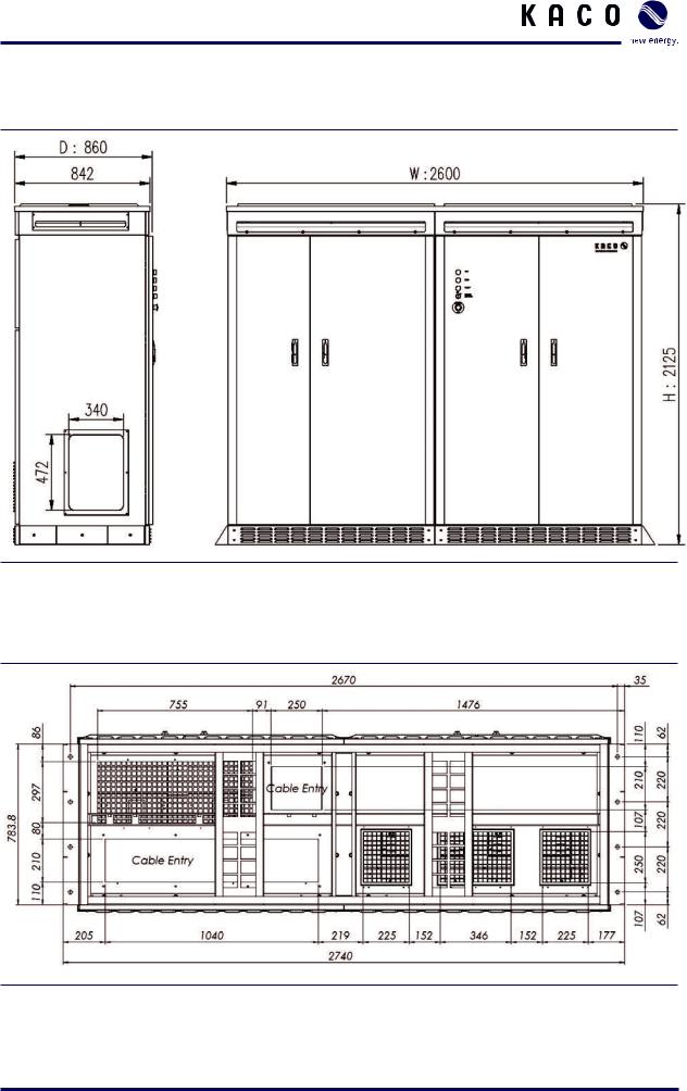
Dimensions(H/W/D) in mm |
|
2125 / 2600 / 860 |
Weight |
|
2200kg |
Power Density |
|
0.100W/cm3 |
Standard |
|
|
|
|
|
EMC |
EN61000-6-2, EN61000-6-4, EN61000-3-3, EN61000-3-12 |
|
Certificates |
|
CE |
Grid monitoring |
In accordance with BDEW directive |
|
|
|
RD1663 |
Features |
|
|
|
|
|
Ground fault detection |
|
Yes |
Heating |
|
Yes |
Emergency stop |
|
Yes |
Overvoltage protection device |
|
Yes / Yes |
AC / DC |
|
|
Overvoltage protection for Ethernet |
|
Yes |
Overvoltage protection device for |
|
Yes |
auxiliary supply |
|
|
Interfaces |
|
|
|
|
|
Communication |
2 × RS485 / Ethernet / Wi-Fi |
|
Analog input |
|
4 × UAI2* |
Argus box string-monitor |
|
RS485 |
User Digital Input / Output3* |
|
1 / 1 |
S0 input / output4* |
|
1 / 1 |
Monitoring Device |
Smart phone (iPhone, Android Phone) |
|
|
|
Tablet pc (iPad) |
|
|
|
Table 1: Electrical data of the inverter
2*UAI: User Analog Input. 4 inputs are 1×irradiation input, 1×module temperature, 1×ambient temperature, 1×wind speed. (Option)
3*UDIO: User Digital Input - 1×Start/Stop signal of the inverter. User Digital Output - 1×External fault signal. 4* So-impulse signal for energy meter.
Page 10 |
Operating Instructions Powador XP500/550-OD-TL |
Unit Description
3.2Dimensions
Figure 1: Dimension of the inverter [mm]
Figure 2: Dimension of the inverter base (Bottom View) [mm]
Operating Instructions Powador XP500/550-OD-TL |
Page 11 |
Unit Description
Figure 3: Minimum workspace requirements of right side [mm]
Figure 4: Minimum workspace requirements of rear side [mm]
Page 12 |
Operating Instructions Powador XP500/550-OD-TL |

Unit Description
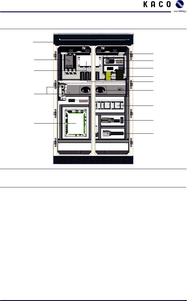
3.3Components inside the inverter
Left side
13
12 |
|
|
|
|
|
|
|
|
|
|
|
|
|
|
1 |
|
|
|
|
|
|
|
|
|
|
|
|
||||
|
|
|
|
||||||||||||
11 |
|
|
|
|
|
|
|
|
|
|
|
|
|
2 |
|
|
|
|
|
|
|||||||||||
|
|
|
|
|
|
|
|
|
|
|
|
|
|
14 |
|
|
|
|
|
|
|
|
|
|
|
|
|
|
|
||
|
|
|
|
|
|
|
|
|
|
|
|
|
|
||
10 |
|
|
|
|
|
|
|
|
|
|
|
|
|
3 |
|
|
|
|
|
|
|
|
|
|
|
|
|
|
|
||
9 |
|
|
|
|
|
|
|
|
|
|
|
|
4 |
||
|
|
|
|
|
|
|
|
|
|
|
|
||||
|
|||||||||||||||
|
|
|
|
|
|
|
|
|
|
|
|
|
|
||
8 |
|
|
|
|
|
|
|
|
|
|
|
5 |
|||
|
|||||||||||||||
|
|
|
|
|
|
|
|
|
|
|
15 |
||||
|
|
|
|
|
|
|
|
|
|
|
|
|
|
||
|
|
|
|
|
|
|
|
|
|
|
|
||||
|
|
|
|
|
|||||||||||
7 |
|
|
|
|
|
|
|
|
|
|
|
|
|
|
6 |
|
|
|
|
|
|
|
|
|
|
|
|
|
|
||
|
|
|
|
|
|
|
|
|
|
|
|||||
|
|
|
|
||||||||||||
Figure 5: Components inside the inverter (left side)
Key
1 |
EMC 1 (EMC Filter on DC) |
8 |
Overvoltage protection (SP1 - DC Side) |
2 |
GFD (Ground fault detection) |
9 Terminals for user connection |
|
|
|
|
|
3 |
PSIM (Master control for interface) |
10 |
CB10 (MCCB for use 1100V DC side) |
4 |
CB20 (MCCB for AC grid connection) |
11 |
DC current transformer |
|
|
|
|
5 |
Overvoltage protection (SP2-AC Side) |
12 |
PEBB (IGBT block) |
|
|
|
|
6 |
Fuse protection for voltage supply |
13 |
Door sensor |
7 |
DC connection |
|
|
|
|
|
|
Fuses information |
|
|
|
|
|
|
|
14 |
F1, F2 |
1000Vdc, 2A, gPV |
|
|
|
|
|
15 |
F1~F12 |
1100Vdc, 250A, gPV |
|
|
|
|
|
Operating Instructions Powador XP500/550-OD-TL |
Page 13 |
Unit Description
Right side
12
11
10
9
8
Figure 6: Components inside the inverter (right side)
Key
13
1
2
3
4
5
6
7
14
1 |
FRT Diode |
7 |
EMC Filter for control power |
2 |
CTR (1PH Transformer) |
8 |
XCU Module |
|
|
|
|
3 |
FRT TR (1PH Transformer) |
9 |
AC current transformer |
|
|
|
|
4 |
Capacitor for FRT |
10 |
Filter capacitor |
5 |
Fan for Reactor Cooling |
11 MC21 (Contactor for grid connection) |
|
|
|
|
|
6 |
SMPS |
12 |
Door sensor |
|
|
|
|
Fuses information |
|
|
|
|
|
|
|
13 |
F38, F39 |
600V, 15A, fast-acting |
|
|
|
|
|
14 |
F30, F31, F36 |
600V, 8A, fast-acting |
|
14 |
F34, F35 |
600V, 15A, fast-acting |
|
|
|
|
|
Page 14 |
Operating Instructions Powador XP500/550-OD-TL |

Transportation and Delivery
4 Transportation and Delivery
4.1Delivery
The inverters leave our factory in proper electrical and mechanical condition. Special packaging ensures that they are transported safely. The shipping company is responsible for any damage that occurs during transportation.
4.1.1Scope of delivery
•XP500/550-OD-TL
•Documentation
Check your delivery
Inspect the inverter thoroughly.
Notify the shipping company immediately if you discover any damage to the packaging which indicates that the inverter may have been damaged or if you discover any visible damage to the inverter.
Send the damage report to the shipping company right away. It must be received by them within six days following receipt of the inverter. We will be glad to help you, if necessary.
4.2Transportation
The inverter should be shipped using the original packaging to ensure that it is transported safely. The inverter cabinets is delivered on a pallet.
Operating Instructions Powador XP500/550-OD-TL |
Page 15 |
Transportation and Delivery
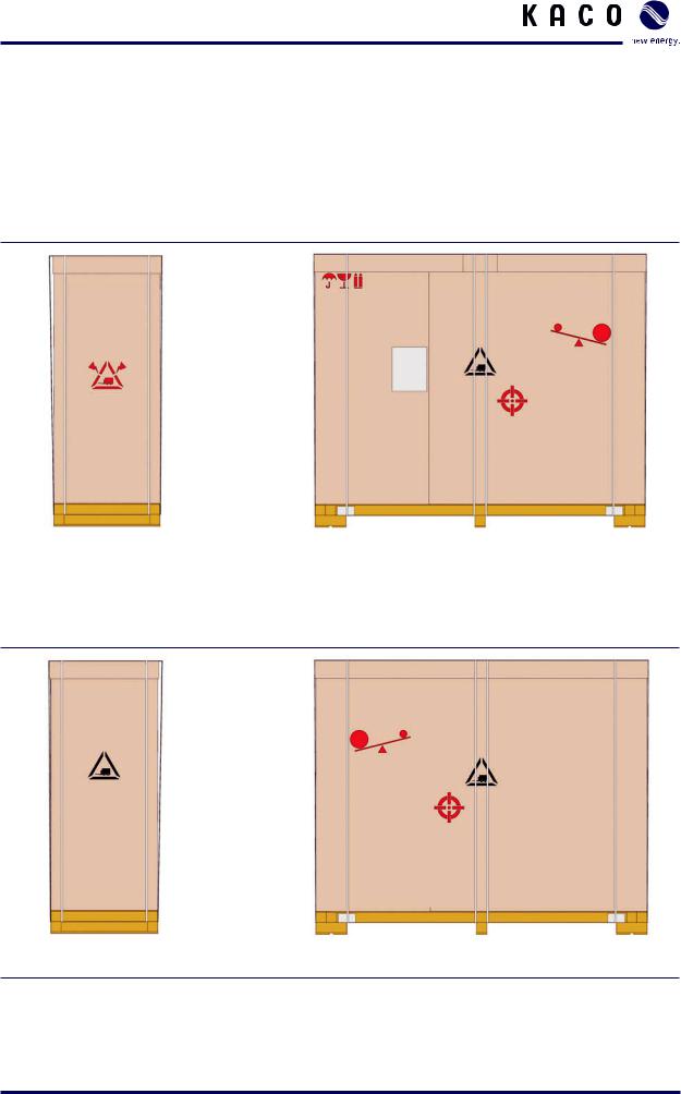
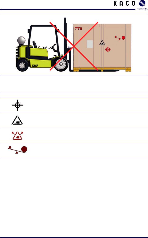
4.3Centre of Gravity of the Inverter
The centre of gravity of the inverter is not in the middle of the XP500/550-OD-TL. Take this into consideration when transporting the XP500/550-OD-TL.
The centre of gravity of the inverter is marked with the centre of gravity symbol on the packaging and the enclosure.
Don‘t Lift This Side
Center of gravity
Left |
Front |
|
|
Figure 7: Centre of gravity by Front side
Right |
Back |
Figure 8: Centre of gravity by Rear side
Page 16 |
Operating Instructions Powador XP500/550-OD-TL |
Transportation and Delivery
Figure 9: Don’t lift by left side
Symbol Explanation
Centre of gravity of the inverter
Can lift from a this side of inverter
Don’t lift from a this side of inverter
The centre of gravity is not center of inverter
Table 2: Symbols on the Packaging
Operating Instructions Powador XP500/550-OD-TL |
Page 17 |
Storage/Installation/Start-up
5 Storage/Installation/Start-up
5.1Storage
When inverters are in storage, the following conditions are required. If not, this may cause failures. The company will not be responsible for the problems if following condition is not observed.
•The unit should be stored indoor in its original packaging when it’s being stored more than 6 months. If its original packaging is removed, it should be stored indoor in a cool, dry place.
•When the unit is stored outdoor, please keep the remained original packaging and do not leave the unit outside for long term period.
•Storage temperature: -20°C ~ +70°C
•When inverter is stored under high humidity condition for long term period, it has to be dried out sufficiently more than 1 day before connecting to the power.
CAUTION
Inverter Storage Caution
Inverters need to be sotred at the correct temperature and correct humidity. If not, this may cause failures.
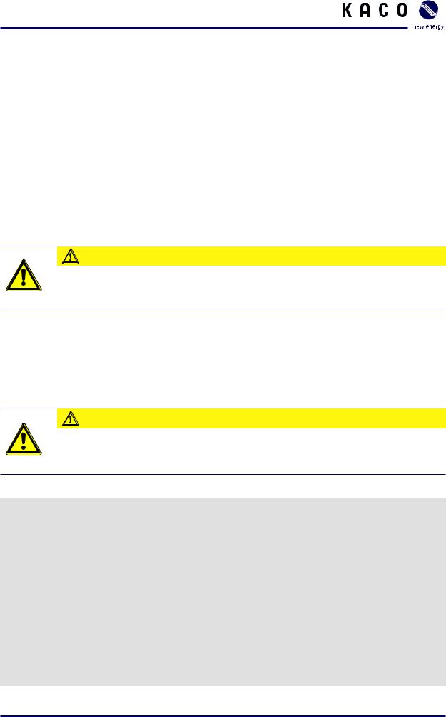
5.2Transporting the unit to the installation location
Once it has arrived at the installation location, the inverter may be transported using the designated eyebolts or fork-lift. These are located on the top of the inverter housing.
CAUTION
Impact hazard, risk of breakage to the inverter
The centre of gravity is located in the upper part of the inverter. › Transport the inverter in an upright position.
Transporting the inverter
Transporting the inverter using eyebolts
Transport the inverter in an upright position.
Connection the rope to the two eyebolts on the left.
Connection the rope to the two eyebolts on the right.
Attach both ropes to a hook, making sure that the ropes do not cross each other. *The rope length: 1650mm over
Position the hook at the middle of the unit.
Transporting the inverter using fork-lift
Remove the front cover of base frame.
Page 18 |
Operating Instructions Powador XP500/550-OD-TL |
Storage/Installation/Start-up
[Eye Nut]
[Fork Lift]
Figure 10: Transporting the unit at the installation location
Figure 11: Transporting the using eyebolts
Operating Instructions Powador XP500/550-OD-TL |
Page 19 |

Storage/Installation/Start-up
5.3Selecting the installation location
NOTE
The maximum ßow rate of the cooling air is 6940m³ per hour.
Please keep this value in mind when you select the installation location.
Figure 12: Ventilation for the inverter [mm]
Page 20 |
Operating Instructions Powador XP500/550-OD-TL |
Storage/Installation/Start-up
5.4Electrical connection
DANGER
Lethal voltages are still present in the terminals and lines of the inverter even after the inverter has been switched off and disconnected!
Coming into contact with the lines and terminals in the inverter will cause serious injury or death.
Only authorised electricians who are approved by the supply grid operator may open, install and maintain the inverter.
›Use extreme caution when working on the unit.
›Disconnect the AC and DC sides.
›Secure them against being inadvertently switched back on.
›Connect the inverter only after the aforementioned steps have been taken.
5.4.1Protective earth connection
Connect the PE bus bars
The PE (protective earth) bus bars are located on the left and right sides of the inverter cabinets.
Connect the wires for “both” PE bus bars.
Earth the inverter
Determine the lay-out of the permanent wiring.
Secure the protective earths (tightening torque for PE terminals: 43Nm). Do not use plug connections.
Check whether all connected cables are securely attached and protected from mechanical forces.
Attach the Plexiglas cover.
Figure 13: PE busbar
Operating Instructions Powador XP500/550-OD-TL |
Page 21 |
Storage/Installation/Start-up
5.4.2 Connecting to the external transformer (AC connection)
The inverter is connected to the power grid using a 3-phase connection. The connection for the power grid is located in the left side of the housing, at the bottom.
Use the screws that are supplied to screw down the bus bars on both sides.
Connection data
Number of AC Cables (A,B,C) |
12 |
Max. Cable diameter for each phase |
240mm2 x 4 |
Tightening torque for AC terminal connections |
43Nm |
Cable lug hole size |
12mm ~ 14mm |
Connect the cables
Each cable corresponds to one phase.
Guide the cables through the opening. Be sure to connect each of the cables to the correct terminal.
Screw down the cables.
Check to make sure that all of the cables are securely attached.
Figure 14: AC connection
Page 22 |
Operating Instructions Powador XP500/550-OD-TL |

Storage/Installation/Start-up
5.4.3Requirements for cable routing between transformer and inverter (AC connection)
WARNING
Fire hazard due to overheating of cables
Differing cable lengths result in overheating of the cables.
› All line conductors from the inverter to the transformer must be of the same length.
The followings are requirements for avoiding current imbalances and cable overheating:
•The minimum size of conductor must be designed based on Table24 of IEC62109-1 2010.
•The AC cables must be bundled in a three-phase system (Required to use cables of the equal type, diameter and length).
•Between the transformer and the inverter there must be four separate cable routes for the AC cables.
•Lay one A, B and C line conductor in each cable route. Ensure that the distance between the cable bundles at least doubles the cable diameter.
Figure 15: Arrangement of AC cables with 4-cable-per-line conductor (example)
Operating Instructions Powador XP500/550-OD-TL |
Page 23 |
Storage/Installation/Start-up
5.4.4 Connection for the PV generator (DC connection)
The DC connection is located in the left side of the housing, at the bottom.
Connection data
Tightening torque for DC terminal connections |
43Nm |
Max. Cable diameter for each fuse |
240mm2 x 2 |
Cable lug hole size |
12mm ~ 14mm |
Fuse protection for DC connection |
250A, 1100V |
|
6 fuses each for DC+ / DC- |
DANGER
Lethal voltages in the PV system
Lethal voltages are present in the PV system.
› Make absolutely sure that the plus and minus poles are properly insulated.
Connect the cables
Each cable corresponds to a specific pole.
Connect the cables to the poles. Make sure the polarity is correct.
Screw down the cables.
Check to make sure that all of the cables and seals are securely attached.
NOTE
Please refer to DC Connector Installation manual (NH Fuse Type).
Figure 16: DC connection
NOTE
Use only the optional earthing kit to earth the PV generator.
Page 24 |
Operating Instructions Powador XP500/550-OD-TL |

Storage/Installation/Start-up
5.4.5Connection for the DC Cable
Figure 17: Bolt & NH Fuse
Item |
|
Description |
|
|
|
A |
M12 Bolt |
Fuse Cover-1 |
|
|
|
B |
Flat Washer |
Fuse Cover-2 |
|
|
|
C |
Spring Washer |
Fuse |
|
|
|
D |
M12 Nut |
Fuse Base |
|
|
|
Table 3: Parameters of operating states
Operating Instructions Powador XP500/550-OD-TL |
Page 25 |

Storage/Installation/Start-up
Single-cable |
Dual-cable |
1 |
1 |
2 |
2 |
3 |
3 |
4 |
4 |
NOTE
Bolt Torque: 43Nm
Page 26 |
Operating Instructions Powador XP500/550-OD-TL |
Storage/Installation/Start-up
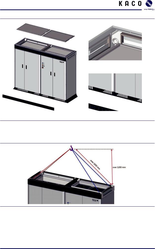
5.5Start-up
Before starting the inverter, if components are condensed inside the inverter or have been stored in a highly humid air for a long time, it has to be dried out enough for more than a day, otherwise it will cause failure. After that the circuit breakers must be switched ON to start the inverter, which also switches on the control circuits.
DANGER
Lethal voltages are still present in the terminals and lines of the inverter even after the inverter has been switched off and disconnected!
Coming into contact with the lines and terminals in the inverter will cause serious injury or death.
Only authorised electricians who are approved by the supply grid operator may open, install and maintain the inverter.
›Keep all doors and covers closed when the unit is in operation.
›Do not touch the lines and terminals when switching the unit on and off!
Switch on the circuit breakers or Fuse
Step |
|
Check |
Action |
|
|
|
|
1 |
Fuse F30, 31, 34, 35, 36, 38, 39 |
ON |
Proceed to Step 2 |
|
Circuit breakers CB32, 40 |
|
|
|
OFF |
Switch on, |
|
|
|
||
|
|
|
Then proceed to Step 2 |
|
|
|
|
2 |
Circuit breakers MCB20, 21 |
ON |
Proceed to Step 3 |
|
Circuit breakers CB20 |
|
|
|
OFF |
Switch on, |
|
|
|
||
|
|
|
Then proceed to Step 3 |
|
|
|
|
3 |
Circuit breaker CB37 |
|
Switch on |
|
|
|
Then proceed to Step 4 |
|
|
|
|
4 |
Key switch |
ON |
Inverter ON |
|
|
|
|
|
|
OFF |
Inverter OFF |
|
|
|
|
NOTE
For NG and PG type Inverter, please do not operate MCB20 arbitrarily.
It may cause failure of the unit.
Operating Instructions Powador XP500/550-OD-TL |
Page 27 |

Storage/Installation/Start-up
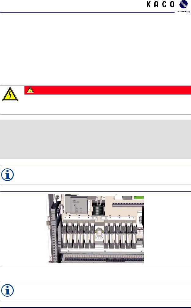
1
1, 2, 3
2
1
Figure 18: Cabinet (interior view)
Key
1Fuse F30, 31, 34, 35, 36, 38, 39 Circuit breakers CB32, 40
2Circuit breakers MCB20, 21 Circuit breakers CB20
3Circuit breaker CB37
When voltage is present at the inverter, it can be started up. Use the HMI interface to start up the inverter.
The inverter begins operation in a specified sequence. For more information, see section 5.2 (“Transporting the unit to the installation location”).
If a fault occurs, the inverter cannot begin operation. For more information on faults, see section 6 (“Faults and Warnings”).
NOTE
If the fault cannot be reset using ÒFault resetÓ, please contact our service department.
Page 28 |
Operating Instructions Powador XP500/550-OD-TL |
Storage/Installation/Start-up
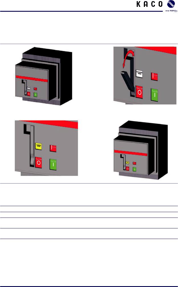
Since CB20 cannot be switched ON/OFF by Key switch, it must be operated manually.
CB20 is a MCCB which can be ON after charged and then OFF without further charging. (one cycle) When operating, the process below showing how to turn on and off CB20 must be followed.
1 |
2 |
3 |
4 |
Figure 19: On/off operation of CB20
Key
1The default appearance of CB20, with black-on-white phrase “DISCHARGED SPRING”.
2After pulling out the handle, move it back and forth continuously until the CB20 gets charged.
3When charged, the black-on-white phrase “DISCHARGED SPRING” turns to be “CHARGED SPRING” in black-on-yellow.
4Push “Push ON” button to switch ON CB20, then the state of CB20 will go back to the state of ‘Key 1’. To switch it OFF, press the “Push OFF” button.
Operating Instructions Powador XP500/550-OD-TL |
Page 29 |

Storage/Installation/Start-up
5.6Operation
DANGER
Lethal voltages are still present in the terminals and lines of the inverter even after the inverter has been switched off and disconnected!
Coming into contact with the lines and terminals in the inverter will cause serious injury or death.
Only authorised electricians who are approved by the supply grid operator may open, install and maintain the inverter.
›Keep all doors and covers closed when the unit is in operation.
›Do not touch the lines and terminals when switching the unit on and off!
5.6.1Operating states
The Inverter has eight operating states. The explanations about each state are below.
Disconnected (default) |
Before operation has commenced the inverter is in the disconnected state. In |
|
this state, the inverter is totally isolated from the PV array and the utility grid. |
|
|
Connecting to the PV array |
When the inverter is in the “Disconnected” state, the ‘Key Switch On’ com- |
|
mand is operated and the PV voltage is kept above 400V for 5 seconds, the |
|
system turns on the PV Array side contactor (PV_MC). |
|
|
Connecting to Grid |
When the inverter is in the “Connecting to PV Array” state and the PV volt- |
|
age is kept above the value of “MPPT V Start” parameter during the time set |
|
by “MPPT T start” parameter, the contactor on the grid side is turned on. The |
|
inverter keeps this state for 8 seconds. |
|
|
Initializing MPP |
The inverter calculates the MPPT start voltage which is product of measure- |
|
ment of PV voltage and the parameter “MPP Factor”. After 5 seconds, the |
|
inverter system enters into the “MPP start” state. |
|
|
MPP start |
In this state, the inverter controls the PV voltage. Reference of the PV voltage |
|
is determined by MPPT start voltage which is calculated at “Initializing MPP” |
|
state. |
|
|
MPPT |
If the PV voltage approximates the MPP start voltage (value of “MPPT V Start” |
|
parameter), the MPPT will start. The inverter follows the MPP target value |
|
automatically, which is varied by irradiance values. If the MPP target value is |
|
out of the allowable MPPT range ([MPP start voltage – MPP Range lower] ~ |
|
[MPP start voltage + MPP range upper]), the system will return to the “Initial- |
|
izing MPP” state and will recalculate the MPPT start voltage. |
|
|
System stop |
When the key switch is off, the PV Array side contactor and the Grid side |
|
contactor are turned off and the system stops. If the output power of inverter |
|
is kept below value of “MPPT P stop” parameter during time of “MPPT T |
|
stop” parameter, connection to the grid is terminated. |
|
|
Table 4: Operating states |
|
Page 30 |
Operating Instructions Powador XP500/550-OD-TL |

Storage/Installation/Start-up
Fault |
If a fault occurs during operation, the system stops. The system resets the |
|
fault and tries to remove the fault. In the case that system removes a fault |
|
successfully, system restarts all by itself. The system tries to remove the fault |
|
at intervals of “MPPT Start” parameter since the last try until trial count |
|
reaches to the number set in an “Auto Fault Reset Count” parameter. After |
|
the number reaches to the “Auto Fault Reset Count” parameter, the system |
|
will log an error and the system will not try to restart. In this case, XP500/550- |
|
OD-TL inverter will try to remove the fault again using key Switch On com- |
|
mand (after turning off by key Switch). |
|
|
Table 4: Operating states |
|
NOTE
If The System doesnÕt try to remove the fault, please contact our service hotline.
Operating Instructions Powador XP500/550-OD-TL |
Page 31 |
 Loading...