


 Loading...
Powador
XP200-HV TL
XP250-HV TL
XP350-HV TL
Operating Instructions
nEnglish Version

Operating Instructions
for Installers and Operators
Table of contents |
|
|
1 |
General notes............................................. |
4 |
1.1 |
About this documentation.................................. |
4 |
1.2 |
Design characteristics........................................... |
4 |
2 |
Safety instructions.................................... |
6 |
2.1 |
Intended use............................................................. |
6 |
2.2 |
Standards and directives...................................... |
6 |
3 |
Unit description......................................... |
7 |
3.1 |
Dimensions............................................................... |
7 |
3.2 |
Overview circuit diagram..................................... |
8 |
3.3 |
Components inside the inverter....................... |
9 |
4 |
Technical data........................................... |
11 |
4.1 |
Electrical data.......................................................... |
11 |
4.2 |
Mechanical data..................................................... |
12 |
5 |
Transportation and Delivery................... |
13 |
5.1 |
Delivery..................................................................... |
13 |
5.2 |
Transportation........................................................ |
13 |
5.3 |
Storage conditions............................................... |
14 |
6 |
Mounting the inverter.............................. |
15 |
6.1 |
Selecting the installation location................... |
15 |
6.2 |
Preparing the installation site.......................... |
16 |
7 |
Installation............................................... |
18 |
7.1Connecting the inverter cabinets
|
electrically............................................................... |
18 |
7.2 |
Connecting protective earth............................ |
19 |
7.3Connecting to the external transformer
(grid connection).................................................. |
20 |
7.4Connecting the PV generator
|
(DC connection)..................................................... |
22 |
7.5 |
Connecting the power supply......................... |
23 |
Powador
XP200-HV TL
XP250-HV TL
XP350-HV TL
7.6 |
Connecting the interfaces................................. |
26 |
7.7 |
Preparing the start-up......................................... |
34 |
8 |
User interface........................................... |
38 |
8.1 |
User interface (MMI) ............................................ |
38 |
8.2 |
MMI menu structure............................................ |
39 |
8.3 |
MMI main menu.................................................... |
41 |
8.4 |
MMI submenus...................................................... |
42 |
8.5 |
Parameters.............................................................. |
52 |
9 |
Configuration............................................ |
61 |
9.1 |
Configuring the interfaces................................. |
61 |
9.2 |
Medium voltage guideline............................... |
66 |
9.3 |
Temperature dependent power derating.... |
70 |
9.4 |
Configuring the e-mail server.......................... |
70 |
10 |
Operation................................................. |
76 |
10.1 |
Starting up the inverter...................................... |
76 |
10.2 |
Operating states.................................................... |
77 |
11 |
Maintenance/Cleaning............................ |
79 |
11.1 |
Maintenance intervals......................................... |
79 |
11.2 |
Cleaning and replacing the fans...................... |
81 |
11.3 |
Cleaning and replacing the outlet filters...... |
82 |
12 |
Faults and Warnings................................ |
83 |
12.1 |
Warnings.................................................................. |
83 |
12.2 |
Errors........................................................................ |
84 |
13 |
Service...................................................... |
86 |
14 |
Decommissioning/Dismantling............. |
87 |
15 |
Disposal.................................................... |
87 |
16 |
EU Declaration of Conformity................ |
88 |
Operating Instructions Powador XP200-HV TL, XP250-HV TL, XP350-HV TL_EN |
Page 3 |

General notes
1 General notes
1.1About this documentation
WARNING
Improper handling of the inverter can be dangerous
›› You must read and understand the operating instructions before you can install and use the inverter safely.
1.1.1Other applicable documents
During installation, observe all assembly and installation instructions for components and other parts of the system. These instructions are delivered together with the respective components and other parts of the system.
Some of the documents which are required to register your photovoltaic system and have it approved are included with the operating instructions.
1.1.2Retention of documents
These instructions and other documents must be stored near the system and be available whenever they are needed.
1.2Design characteristics
1.2.1Symbols used in this document
General danger symbol |
Risk of fire or explosion |
|
|
|
|
High voltage |
|
Risk of burns |
Electrician |
If indicated, only electricians are allowed to execute the work. |
|
1.2.2Description of safety instructions
DANGER
Imminent danger
Failure to observe this warning will lead directly to serious bodily injury or death.
WARNING
Potential danger
Failure to observe this warning may lead to serious bodily injury or death.
CAUTION
Low-risk hazard
Failure to observe this warning will lead to minor or moderate bodily injury.
CAUTION
Hazard with risk of property damage
Failure to observe this warning will lead to property damage.
Page 4 |
Operating Instructions Powador XP200-HV TL, XP250-HV TL, XP350-HV TL_EN |

General notes
1.2.3Depiction of additional information
NOTE
Useful information and notes.
DE |
Country-specific functions |
|
Functions that are limited to one or more countries are indicated with country codes according to ISO 3166-1.
1.2.4Description of actions
a)One-step instruction or instruction steps that can be performed in any order.
Action
Prerequisite(s) for performing an action (optional) "" Perform this action
"" (Possibly additional actions)
»»The result of your action(s) (optional)
b)Multi-step instruction with specified order.
Action
Prerequisite(s) for performing an action (optional)
1.Perform first action
2.Perform second action
3.(Possibly additional actions)
»»The result of your action(s) (optional)
1.2.5Abbreviations
BDEW |
Bundesverband der Energieund Wasserwirtschaft (German Energy and Water Association) |
|
CB |
Circuit Breaker |
|
DSP |
Digital Signal Processor |
|
FPGA |
Integrated circuit for digital technology (Field Programmable Gate Array) |
|
FRT |
Capability of a PV system to remain on the grid during short circuits (Fault Ride Through) |
|
IGBT |
Semiconductor device (Insulated Gate Bipolar Transistor) |
|
MC |
Magnetic Contactor |
|
MMI |
User interface (Man Machine Interface) |
|
MPP |
Point of the current-voltage diagram of a solar cell at which the maximum amount of power can be |
|
|
drawn (Maximum Power Point) |
|
MPPT |
The MPP tracker adjusts the voltage to the MPP value. |
|
NVSRAM |
Permanent memory in which fixed parameters are stored (Non-Volatile Static Random Access Memory) |
|
PEBB |
Power electronics module (Power Electronics Building Block) |
|
PLL |
Phase-synchronising circuit (Phase-Locked Loop) |
|
PSIM |
Master control for the interfaces in the unit (PEBB Signal Interface Master) |
|
PWM |
Pulse Width Modulation |
|
SELV |
Safety Extra-Low Voltage |
|
SPD |
Surge Protection Device |
|
|
|
|
Operating Instructions Powador XP200-HV TL, XP250-HV TL, XP350-HV TL_EN |
Page 5 |
|

Safety instructions
2 Safety instructions
DANGER
Lethal voltages are still present in the terminals and lines of the inverter even after the inverter has been switched off and disconnected!
Coming into contact with the lines and terminals in the inverter will cause serious injury or death.
Only authorised electricians who are approved by the supply grid operator are allowed to open, install and maintain the inverter.
›› Keep all doors and covers closed when the unit is in operation.
›› Do not touch the lines and terminals when switching the unit on and off. ›› Do not modify the inverter.
The electrician is responsible for observing all existing standards and regulations.
•Hold unauthorised persons away from the inverter and from the PV system.
•Above all, be sure to observe standard IEC 60364-7-712:2002, “Requirements for Special Installations or Locations – Solar Photovoltaic (PV) Power Supply Systems”.
•Ensure operational safety by providing for proper grounding, conductor dimensioning and appropriate protection against short circuit.
•Observe the safety instructions located on the inner sides of the doors.
•Switch off all voltage sources and secure them against being inadvertently switched back on before performing visual inspections and maintenance.
•When taking measurements while the inverter is live:
–– Do not touch the electrical connections.
–– Remove jewellery from your wrists and fingers.
–– Make sure that the testing equipment is in good and safe operating condition.
•Stand on an insulated surface when working on the inverter.
•Modifications to the surroundings of the inverter must comply with national and local standards.
2.1Intended use
The inverter converts the DC voltage generated by the photovoltaic (PV) modules into AC voltage and
feeds this into the power grid. The inverter is built according to the state of the art and recognised safety rules. Nevertheless, improper use may cause lethal hazards for the operator or third parties, or may result
in damage to the unit and other property.
The inverter may be operated only with a permanent connection to the public power grid.
Any other or additional use is not considered the intended use. Examples of unintended use include:
•Mobile use
•Use in rooms where there is a risk of explosion
•Use in rooms where the humidity is higher than 95%
2.2Standards and directives
The inverter is labelled with the CE sign and fulfils the appropriate EMC standards and guidelines.
NOTICE
The declaration of conformity with the applicable standards and guidelines can be found in the appendix.
Information about country-specific standards and safety settings as well as additional application notes are available at our website http://www.kaco-newenergy.de.
Page 6 |
Operating Instructions Powador XP200-HV TL, XP250-HV TL, XP350-HV TL_EN |

Unit description
3 Unit description
3.1Dimensions
50
1970 2120
870
Figure 1: Dimensions of the inverter [mm]
Figure 2: Dimensions of the inverter base [mm]
Operating Instructions Powador XP200-HV TL, XP250-HV TL, XP350-HV TL_EN |
Page 7 |
Unit description
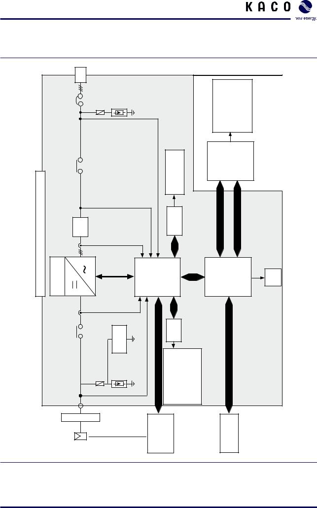
3.2Overview circuit diagram
|
123 |
|
|
|
|
|
|
|
|
|
|
|
|
L |
|
|
|
|
|
|
|
|
|
|
|
|
CB20 |
Surge |
|
|
|
|
|
|
Commissioning and Maintenance Tool (CMT) Parameter Setting |
|
Status Monitoring |
|
|
Protector |
|
|
|
|
|
|
|
||||
|
g,abc |
|
|
|
|
|
|
Trace |
||||
|
|
V |
|
|
|
|
|
|
|
|
|
|
/ XP350-HV TL |
MC21 |
VC,abc |
|
|
Temperature Irradation Reference cell etc. |
|
|
|
Monitoring Subsystem |
|
|
|
XP250-HV TL |
LC Filter |
|
|
|
|
ANI |
|
|
USB |
Ethernet |
|
|
TL / |
|
Iinv,abc |
|
|
|
|
|
|
|
|
|
|
XP200-HV |
|
|
|
|
|
|
|
|
|
|
|
|
|
|
|
|
|
|
|
|
|
|
|
|
|
Central Inverter |
Inverter |
|
|
Control Subsystem |
|
RS232 |
|
Subsystem |
|
|
||
|
|
|
|
|
MMI |
|
SD card |
|||||
|
|
Idc |
|
|
|
|
|
|
|
|
|
|
|
CB10 |
Surge Isolation Protector Monitoring |
|
|
|
DIO |
|
|
|
|
|
|
|
pv |
CAN or RS485 |
S0-Input (1 Channel) |
S0-Output (1 Channel) |
DigitalInput (1 Channel) |
DigitalOutput (1 Channel) |
RS485 |
|
|
|
||
|
V |
|
|
|
||||||||
|
450 ... 830 V DC |
|
|
|
|
|
|
|
|
|
|
|
|
PV Modules |
|
|
|
PVM (Module Monitoring |
|
|
|
|
Monitoring |
|
|
Figure 3: Configuration of the Powador XP200-HV TL / XP250-HV TL / XP350-HV TL
Page 8 |
Operating Instructions Powador XP200-HV TL, XP250-HV TL, XP350-HV TL_EN |

Unit description
3.3Components inside the inverter
The inverter components are installed inside two cabinets.
Components inside the left cabinet
A–A |
A |
B |
B–B |
17 
16 |
|
|
|
|
15 |
|
|
|
|
|
|
|
3 |
|
|
|
|
4 |
|
14 |
|
|
5 |
1 |
|
|
|
||
|
|
|
|
|
|
|
|
5 |
|
13 |
|
|
6 |
|
|
|
7 |
|
|
12 |
|
|
|
|
11 |
|
|
8 |
|
|
|
|
9 |
|
A |
10 |
B |
|
2 |
|
|
|
Figure 4: Components inside the left cabinet (XP200-HV)
Key
1 |
24 V voltage supply EMC filter for the MMI |
10 |
DC overvoltage protection |
|
|
|
|
|
|
2 |
Grounding bar |
11 |
DC connection (left side DC+, right side DC–) |
|
|
|
|
|
|
3 |
Ground fault detection |
12 |
DC fuses (number of fuses depends on inverter type) |
|
4 |
PSIM (master control for interfaces) |
13 |
Terminals for user connector |
|
|
|
|
|
|
5 |
24 V voltage supply |
14 |
DC disconnector |
|
|
|
|
|
|
6 |
Control system (XCU) |
15 |
DC current measurement |
|
7 |
Fuse protection for voltage supply and |
16 |
PEBB (IGBT block) |
|
|
measuring |
equipment; overvoltage protection |
|
|
|
for the voltage supply for the controller |
|
|
|
|
|
|
|
|
8 |
Auxiliary transformer |
17 |
Door sensor |
|
|
|
|
|
|
9 |
FRT components |
|
|
|
Operating Instructions Powador XP200-HV TL, XP250-HV TL, XP350-HV TL_EN |
Page 9 |

Unit description
Components inside the right cabinet
A–A |
A |
B |
B–B |
|
12 |
|
1 |
|
|
|
2 |
|
11 |
|
3 |
|
|
|
|
|
10 |
|
4 |
|
|
|
|
9 |
|
5 |
|
|
|
|
|
8 |
|
|
|
7 |
|
6 |
|
|
|
|
|
A |
|
B |
Figure 5: Components inside the right cabinet |
|
|
|
Key |
|
|
|
1 |
Door sensor |
7 |
Grounding bar |
2 |
EMC filter |
8 |
LC filter (capacitor) |
3 |
AC switch |
9 |
AC overvoltage protection and fuse protection |
4 |
LC filter (line choke) |
10 |
AC current measurement |
5 |
Transformer |
11 |
AC contactor |
6 |
AC connection to the external transformer |
12 |
AC fans |
Page 10 |
Operating Instructions Powador XP200-HV TL, XP250-HV TL, XP350-HV TL_EN |
Technical data
4 |
Technical data |
|
|
|
4.1 |
Electrical data |
|
|
|
|
|
|
|
|
Input levels |
XP200-HV TL |
XP250-HV TL |
XP350-HV TL |
|
|
|
|
|
|
Max. PV generator power [kW] |
240 |
300 |
420 |
|
|
|
|
|
|
MPPT range [V] |
|
450 ... 830 |
|
|
|
|
|
|
|
No-load voltage [V] |
|
1000* |
|
|
|
|
|
|
|
Monitoring of input voltage [V] |
|
Stand-by from Von > 300 |
|
|
|
|
Night shutdown from Voff < 250 |
|
|
|
|
MPP starting voltage Vstart > 600 |
|
|
Voltage ripple [%] |
|
< 3 |
|
|
|
|
|
|
|
Current ripple [%] |
|
< 4 |
|
|
|
|
|
|
|
Max. input current [A] |
467 |
611 |
856 |
|
|
|
|
|
|
Output levels |
XP200-HV TL |
XP250-HV TL |
XP350-HV TL |
|
|
|
|
|
|
Rated power [kW] |
200 |
250 |
350 |
|
|
|
|
|
|
Max. power [kW] |
200 |
250 |
350 |
|
|
|
|||
Line voltage |
In accordance with country-specific guidelines |
|||
|
|
|
|
|
Output voltage [V] |
|
290 (±10%) |
|
|
|
|
|
|
|
Rated current [A] |
398 |
498 |
697 |
|
|
|
|
|
|
Max. current [A] |
398 |
498 |
697 |
|
|
|
|
|
|
Rated frequency [Hz] |
|
50/60 |
|
|
|
|
|
|
|
cos phi |
|
0.80 inductive ... 0.80 capacitive |
|
|
|
|
|
|
|
Distortion factor [%] |
|
< 3 at rated power |
|
|
|
|
|||
Fault signal relay |
Potential-free NO contact, max. 30 V/1 A |
|||
|
|
|
||
S0 output |
|
Open collector output, max. 30 V/50 mA |
||
|
|
|
|
|
General electrical data |
XP200-HV TL |
XP250-HV TL |
XP350-HV TL |
|
|
|
|
|
|
Max. efficiency [%] |
98.2 |
98.1 |
98.3 |
|
|
|
|
|
|
European efficiency [%] |
97.8 |
97.8 |
98.0 |
|
|
|
|
|
|
Internal consumption in |
|
< 80 |
|
|
standby mode [W] |
|
|
|
|
|
|
|
|
|
Internal consumption in operation [W] |
|
< 360 |
|
|
|
|
|
|
|
Min. grid feed power [W] |
|
10 000 |
|
|
|
|
|||
Grid monitoring |
In accordance with country-specific guidelines |
|||
|
|
|
|
|
CE conformity |
|
yes |
|
|
|
|
|
|
|
Table 1: Electrical data of the inverter |
|
|
|
|
*To protect the hardware, the inverter starts up only at voltages <950 V
Operating Instructions Powador XP200-HV TL, XP250-HV TL, XP350-HV TL_EN |
Page 11 |

Technical data
4.2Mechanical data
|
|
|
XP200-HV TL |
XP250-HV TL |
XP350-HV TL |
|
|
|
|
|
|
Display |
|
|
TFT LCD touchscreen |
|
|
|
|
|
|
|
|
Interfaces |
|
|
RS485/Ethernet/USB |
|
|
|
|
|
|
4 x analogue inputs |
|
|
|
|
|
1 x digital input |
|
|
|
|
|
1 x S0 input |
|
|
|
|
|
1 x digital output |
|
|
|
|
|
1 x S0 output |
|
|
|
|
|
||
Memory [GB] |
|
SD card, up to 8 |
|
||
|
|
||||
Operating temperature range [°C] |
–20 ... +50 full rated power, no derating |
||||
|
|
|
|
||
Storage temperature range [°C] |
|
–20 ... +70 |
|
||
|
|
|
|
||
Relative humidity [%] |
|
0 ... 95 |
|
||
|
|
|
|
||
Cooling [m³/h] |
Fan, max. 4040 |
Fan, max. 4040 |
Fan, max. 5460 |
||
• |
part A |
|
max. 2840 |
max. 2840 |
max. 4260 |
• |
part B |
|
max. 1200 |
max. 1200 |
max. 1200 |
|
|
||||
Protection rating |
IP 21 (in accordance with DIN EN 60529:2000) |
||||
|
|
|
Intended for indoor use only in accordance with |
||
|
|
|
|
IEC 62103:2003 |
|
|
|
|
|
||
Noise emission [dB (A)] |
|
< 70 |
|
||
|
|
|
|
|
|
Housing |
|
|
Upright, steel housing |
|
|
|
|
|
|
||
H x W x D [mm] |
|
2120 x 2400 x 870 |
|
||
|
|
|
|
|
|
Base [mm] |
|
|
2400 x 840 |
|
|
|
|
|
|
||
Total weight [kg] |
1170 |
1200 |
1370 |
||
|
|
|
|
|
|
Table 2: |
Mechanical data of the inverter |
|
|
|
|
Page 12 |
Operating Instructions Powador XP200-HV TL, XP250-HV TL, XP350-HV TL_EN |

Transportation and Delivery
5 Transportation and Delivery
5.1Delivery
The inverters leave our factory in proper electrical and mechanical condition. Special packaging ensures
that they are transported safely. The shipping company is responsible for any damage that occurs during transportation.
Scope of delivery
•Powador XP200-HV / Powador XP250-HV
•Documentation
•Material for electrical connection
Identification
The inverters are transported and delivered in two separate parts.
Each part is equipped with a name plate mounted on the inside of the left cabinet door. The name plates identify the inverter.
Check your delivery
"" Make sure that both parts of the inverter are delivered, part A and part B.
"" Make sure that the serial numbers of part A and part B are identical. The serial numbers are to be found on the name plates.
Only inverters with the same serial number for parts A and B are to be used together. "" Inspect the inverter thoroughly.
"" Notify the shipping company immediately if you discover any damage to the packaging which indicates that the inverter may have been damaged or if you discover any visible damage to the inverter.
"" Send the damage report to the shipping company right away. It must be received by them within six days following receipt of the inverter. We will be glad to help you, if necessary.
"" Notify Kaco new energy GmbH if the inverter cabinets have different serial numbers.
5.2Transportation
DANGER
Danger by falling objects, impact or tipping of the inverter
Falling objects may hit persons or damage the inverter.
›› When transporting the inverter, make sure that nobody stands beneath the inverter. ›› Transport the inverter in an upright position. Do not tilt the inverter.
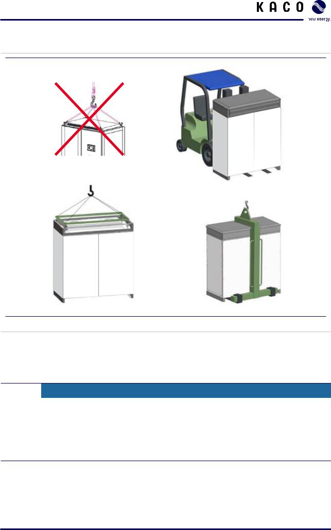
›› Only use lifting devices with a load capacity sufficient for lifting the inverter. ›› Transport the inverter only in its original packaging.
CAUTION
Risk of damage to the inverter
The inverter cabinets are very heavy. The eyebolts on the top of the cabinets may break when using lifting straps without a lifting frame.
›› At installation site transport the inverter only with:
–– forklift or lift truck,
–– crane fork,
–– crane with lifting frame attached to the eyebolts.
Operating Instructions Powador XP200-HV TL, XP250-HV TL, XP350-HV TL_EN |
Page 13 |
Transportation and Delivery
Figure 6: Lifting the inverter
5.3Storage conditions
The inverter is for indoor use only. The packaging of the inverter protects the unit against dust and moisture during transportation and storage. However, the packaging is not suitable for outdoor storage.
CAUTION
Risk of damage to the inverter by incorrect storage
›› Store the inverter:
–– at temperatures between –20°C and 70°C,
–– in the packaging used for delivery,
–– in dry, protected locations only. ›› Avoid humidity in storage locations.
Page 14 |
Operating Instructions Powador XP200-HV TL, XP250-HV TL, XP350-HV TL_EN |
Mounting the inverter

 Electrician
6 Mounting the inverter
6.1Selecting the installation location
NOTE
The maximum flow rate of the cooling air is different for each inverter type:
• Powador XP200-HV TL: 4040 m3/h
•Powador XP250-HV TL: 4040 m3/h
•Powador XP350-HV TL: 5460 m3/h
›› Keep this value in mind when you select the installation location.
Floor
•The floor must have adequate load-bearing capacity (a separate, solid basement may be necessary).
•The building material must meet the requirements of building material class B1 (“Flame-resistant Building Materials”, in accordance with DIN EN 13501-1).
•The floor must consist of non-cracked concrete.
Room
•Permanent access to the installation location for installation and service purposes must be possible.
•The room must provide enough space to work at the inverter in case of maintenance (e.g. exchange of filter mats).
•The room must provide operating conditions according to the technical specification.
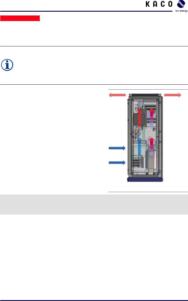
•The necessary amount of cooling air must be available at the installation location.
•Adequate air circulation through the inverter must be guaranteed. Air inlets and outlets must not be blocked.
• Thermal short circuits must be excluded. |
Figure 7: Ventilation for the inverter |
|
"" Ensure that all regulations for emergency situations are considered.
"" Make sure that the escape routes (according to local requirements) are not blocked in any circumstance. "" Do not install the inverter in a room where there is a risk of explosion.
Operating Instructions Powador XP200-HV TL, XP250-HV TL, XP350-HV TL_EN |
Page 15 |

Mounting the inverter

 Electrician
6.2Preparing the installation site
NOTE
The serial numbers of the left and the right inverter cabinet must be identical (see inside of the left cabinet doors).
Do not connect two inverter cabinets with different serial numbers.
Setup of the inverter
Each inverter cabinet is equipped with 6 bore holes on the mounting side (Figure 8). The corresponding screws, nuts and washers are delivered in a plastic bag inside the left inverter cabinet.
The serial numbers of the left and the right inverter cabinet are identical.
1.Connect the two inverter cabinets through the 6 bore holes with the supplied screws, nuts and washers.
2.Tighten the screws (tightening torque: 25 ... 30 Nm).
Figure 8: Mechanical connection between left and right cabinets
Cable routing
"" Lay AC power cables, DC power cables and communication cables separately to avoid interferences. "" Make the same grounding potential available for all communication cables.
"" Ensure proper grounding of all communication cables at the same potential. "" If possible, allow communication cables to be routed close to ground potential.
Requirements for auxiliary supply
"" In case the inverter is used with an external power supply, dimension the external power supply properly. The following values of power consumption serve as reference values.
Page 16 |
Operating Instructions Powador XP200-HV TL, XP250-HV TL, XP350-HV TL_EN |

Mounting the inverter

 Electrician
XP200-HV TL
Measurand |
Internal consumption in standby |
Internal consumption in operation |
|
|
|
Itrms [A] |
0.53 |
2.35 |
Vtrms [V] |
216.6 |
214.9 |
P [W] |
77.3 |
346.3 |
|
|
|
S [VA] |
114.5 |
504.0 |
|
|
|
Q [Var] |
84.5 |
366.2 |
|
|
|
Table 3: Power consumption data of XP200-HV |
|
|
XP250-HV TL |
|
|
|
|
|
Measurand |
Internal consumption in standby |
Internal consumption in operation |
|
|
|
Itrms [A] |
0.53 |
2.41 |
Vtrms [V] |
219.0 |
217.7 |
P [W] |
79.9 |
351.8 |
|
|
|
S [VA] |
115.7 |
525.2 |
|
|
|
Q [Var] |
83.7 |
390.0 |
|
|
|
Table 4: Power consumption data of XP250-HV |
|
|
XP350-HV TL |
|
|
|
|
|
Measurand |
Internal consumption in standby |
Internal consumption in operation |
|
|
|
Itrms [A] |
0.80 |
3.41 |
Vtrms [V] |
216.9 |
215.0 |
P [W] |
99.4 |
486.0 |
|
|
|
S [VA] |
174.5 |
732.5 |
|
|
|
Q [Var] |
143.5 |
548.1 |
Table 5: Power consumption data of XP350-HV TL
Operating Instructions Powador XP200-HV TL, XP250-HV TL, XP350-HV TL_EN |
Page 17 |
Installation

 Electrician
7 Installation
7.1Connecting the inverter cabinets electrically
DANGER
Lethal voltages are still present at the terminals and lines of the inverter even after the inverter has been switched off and disconnected!
Coming into contact with the lines and terminals in the inverter will cause serious injury or death.
Only authorised electricians who are approved by the supply grid operator may open, install and maintain the inverter.
›› Be extremely cautious when working on the unit. ›› Disconnect the AC and DC sides.
›› Secure them against being inadvertently switched back on.
Connect the inverter only after the aforementioned steps have been taken.
NOTE
Only inverters with the same serial number for parts A and B are to be used together.
›› Before connecting the inverter cabinets electrically, make sure that the serial numbers of part A and part B are identical.
An electrical connection must be made between the inverter cabinets. This applies to the controller as well as to the busbars. The busbars are delivered in a plastic bag inside the left inverter cabinet.
Connecting the busbars (Figure 9, item 1)
1.Remove the plexiglas covers and store them for re-installation after the electrical installation.
2.Slide the two busbars through the upper opening in each of the cabinets.
3.Use the screws that are supplied to screw down the busbars on both sides (tightening torque: 30... 40 Nm)
Connecting the controller cables (Figure 9, item 2)
1.Pull the cables for the controller from the left cabinet through the lower opening in each of the cabinets and into the right cabinet.
2.Connect the cables for the controller in the right cabinet. The plug connectors are appropriately marked.
NOTE
The inverter will not operate with incorrect cable connections. ›› Make sure that the controller cables are plugged in correctly.
Page 18 |
Operating Instructions Powador XP200-HV TL, XP250-HV TL, XP350-HV TL_EN |

Installation

 Electrician
1 
2
Figure 9: Electrical connection for the cabinets
Key
1 Busbar connection 2 Controller connection on the right side
7.2Connecting protective earth
1 |
2 |
Figure 10: Protective earth connections
Key
1 PE busbar in the left inverter cabinet 2 PE busbar in the right inverter cabinet
Connecting the PE busbars
The PE (protective earth) busbars are located on the right side of the left inverter cabinet (Figure 10, item 1) and on the left side of the right inverter cabinet (Figure 10, item 2).
"" Connect the wires for both PE busbars.
Operating Instructions Powador XP200-HV TL, XP250-HV TL, XP350-HV TL_EN |
Page 19 |

Installation

 Electrician
Grounding the inverter
"" Determine the lay-out of the permanent wiring. "" Secure the protective earth cables:
–– Max. cross-section: according to regulations
–– Connection bolt: M10
–– Tightening torque: 25 ... 30 Nm "" Do not use plug connections.
"" Check whether all connected cables are securely attached and protected from mechanical forces.
7.3Connecting to the external transformer (grid connection)
The inverter is connected to the power grid via an external transformer using a 3-phase connection. The connection for the power grid is located at the bottom of the right cabinet.
7.3.1Selecting the external transformer
With an appropriate transformer, the inverters of the XP-HV TL series can be connected both to the low voltage grid and the medium voltage grid.
"" Choose the appropriate transformer voltage level depending on the grid connection of the PV plant (low voltage or medium voltage)
NOTE
The XP-HV TL inverters may not operate properly if an inappropriate transformer is used. Especially on the medium voltage level, the inverters require special transformers.
›› Use only transformers that are manufactured according to the specification of KACO.
"" When choosing the transformer for the medium voltage level check the transformer specification available on the KACO-website.
"" In case of questions regarding the specification please contact KACO for assistance.
NOTE
The inverters can be operated with more than one inverter on a single transformer (e.g. 3 XP350HV TL operating as a Megawatt station).
›› Do not connect the inverters in parallel on one coil. ›› Refer to the transformer specification for details.
7.3.2Grid type
NOTE
Only an IT grid is suitable for the XP-HV TL inverters. ›› Connect only an IT grid to the inverter.
›› Do not ground the grid between the inverter and the medium voltage transformer.
Page 20 |
Operating Instructions Powador XP200-HV TL, XP250-HV TL, XP350-HV TL_EN |
Installation

 Electrician
DANGER
Lethal voltages may be present in an IT grid!
Under operating conditions voltages up to 1200 V can be present between phase and ground.
›› Ensure proper dimensioning of the cable between inverter and transformer in terms of voltage resistance (minimum dimensioning voltage: 1200 V)
›› Make sure that no ground faults or short-circuits can occur. Otherwise the inverter may be damaged.
7.3.3Connecting the transformer
Connection data |
|
Max. cable cross-section |
300 mm² |
Connection bolt |
M10 |
Tightening torque for AC terminal connections |
40 ... 50 Nm |
NOTE
If the cables are connected to the wrong terminals, the inverter does not operate.
Connecting the cables
Each cable corresponds to one phase.
"" Guide the cables through the opening.
Be sure to connect each of the cables to the correct terminal.
"" Screw down the cables.
"" Check to make sure that all of the cables are securely attached.
NOTE
If larger diameters are necessary, it is also possible to use two cables for one phase (e.g. 2 x 240 mm²)
1
Figure 11: Bottom of the right cabinet
1 AC connections
Operating Instructions Powador XP200-HV TL, XP250-HV TL, XP350-HV TL_EN |
Page 21 |
Installation

 Electrician
7.4Connecting the PV generator (DC connection)
The DC connection is located at the bottom of the left inverter cabinet (Figure 12).
Connection data
Max. cable cross-section |
300 mm² |
Connection bolt |
M10 |
Tightening torque for DC terminal connections |
40 ... 50 Nm |
Fuse protection for DC connection |
XP200-HV TL: 2 fuses each for DC+/DC– |
|
XP250-HV TL: 3 fuses each for DC+/DC– |
|
XP350-HV TL: 4 fuses each for DC+/DC– |
Ensuring that there is no ground fault
1.Determine the DC voltage between the
–– protective earth (PE) and the positive lead of the PV generator,
–– protective earth (PE) and the negative lead of the PV generator.
If stable voltages can be measured, there is a ground fault in the DC generator or its wiring. The ratio between the measured voltages gives an indication as to the location of this fault.
2.Rectify any faults before taking further measurements.
3.Determine the electrical resistance between the
–– protective earth (PE) and the positive lead of the PV generator,
–– protective earth (PE) and the negative lead of the PV generator.
Low resistance (< 2 MΩ) indicates a high-ohm ground fault of the DC generator.
4.Rectify any faults before connecting the DC generator.
Connecting the cables
DANGER
Lethal voltages in the PV system
Lethal voltages are present in the PV system.
›› Make absolutely sure that the plus and minus poles are properly insulated.
Each cable corresponds to a specific pole.
1.Connect the cables to the poles.
Make sure the polarity is correct (Figure 12):
–– Left side (item 1): Positive (DC+)
–– Right side (item 2): Negative (DC–)
2.Screw down the cables.
3.Make sure that all of the cables and seals are securely attached.
NOTE
If positive or negative grounding of the PV generator is necessary, the use of an optional grounding kit for the XP inverters is mandatory.
›› Do not ground the inverter without the grounding kit.
1 2
Figure 12: DC connections (XP-250 HV)
1 DC+ connections
2 DC– connections
Page 22 |
Operating Instructions Powador XP200-HV TL, XP250-HV TL, XP350-HV TL_EN |

Installation

 Electrician
7.5Connecting the power supply
Without auxiliary power, the inverter is not able to start up and supply the necessary power to the MMI, the fans, measurement equipment, etc. The inverter offers two ways to supply the necessary power:
•Internal power supply (see section 7.5.1 on page 23)
•External power supply (see section 7.5.2 on page 24)
CAUTION
Internal short circuit by incorrect connection
›› Do not use the external and the internal power supply at the same time.
NOTE
In delivery status, the inverter is set for using the external power supply.
For the power consumption of the inverter see section 6.2 on page 16
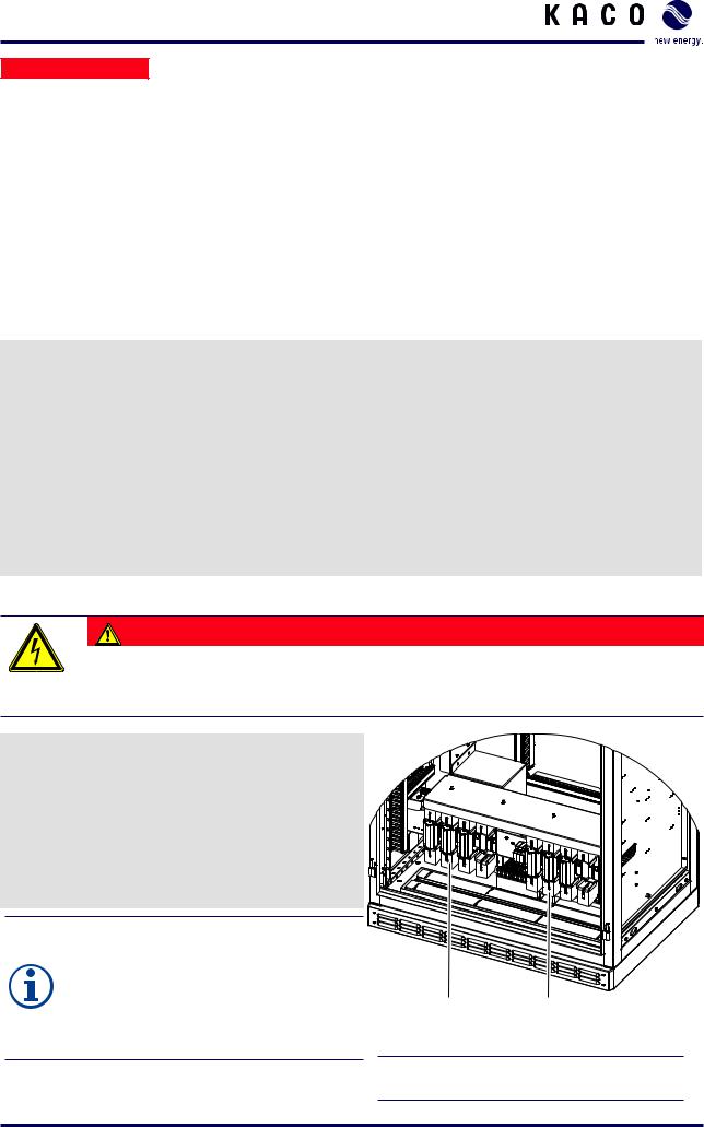
7.5.1Connecting the internal power supply
NOTE
The use of internal power is subject to the following restrictions:
• The inverter can not be operated when no PV power is present.
• The inverter is not able to fulfil any communication tasks without power supply.
•Software updates or external access to the inverter is not possible without power supply.
•The use of internal power reduces the feed-in power and this finally reduces the yield of the PV plant.
No additional terminal connections have to be made for using the internal power supply.
1.Make sure that the circuit breaker CB33 (1) is switched off.
2.Secure the circuit breaker CB33 with the lock clip (2).
CB33 CB37
1 2
Figure 13: Securing the circuit breaker CB33 for the use of the internal power supply
Operating Instructions Powador XP200-HV TL, XP250-HV TL, XP350-HV TL_EN |
Page 23 |
Installation

 Electrician
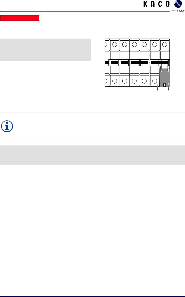
7.5.2Connecting the external power supply
In the standard setting, the inverter is meant to be used with external power supply.
1.Make sure that the circuit breaker CB37 (1) is switched off.
2.Secure the circuit breaker CB37 with the lock clip (2).
CB33 CB37
1 2
Figure 14: Securing the circuit breaker CB37 for the use of the external power supply
NOTE
Cables with a cross-section up to 2.5 mm² may be used for the connection of the external power supply.
Depending on the selected cable cross-section, choose an appropriate protection device (e.g. a C16A circuit breaker is recommended for a 1.5 mm² cross-section).
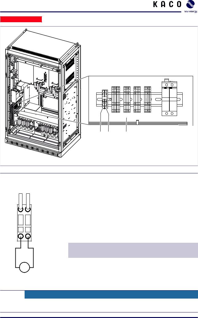
Connecting the external power supply (Figure 15)
The connection for the external power supply is located in the left inverter cabinet.
"" Connect the external power supply to the terminals marked “TO” using single-phase 230 V.
Page 24 |
Operating Instructions Powador XP200-HV TL, XP250-HV TL, XP350-HV TL_EN |
Installation

 Electrician
1 |
2 |
3 |
Figure 15: Connecting the external power supply (XP250-HV)
Key
1 |
230 V L connection (TO L) |
3 |
User interface |
2 |
230 V N connection (TO N) |
|
|
|
|
|
|
1a 2a
-TO
|
|
|
|
|
|
|
|
|
|
|
|
|
|
|
|
|
|
|
|
|
|
|
Terminal |
Terminal |
Specification |
Wire cross-section, |
230 V L |
|
|
|
230 V N |
number |
designation |
|
max. |
|
|
|
|
|
|
|
||
|
|
|
1a |
TO L |
230 V L |
AWG 14 |
||
|
|
|||||||
|
|
|
|
|||||
|
|
|
|
(2.5 mm2) |
||||
|
2a |
TO N |
230 V N |
|||||
|
|
|
||||||
Figure 16: TO AC connection |
Table 6: Connections for external power supply |
|
||||||
CAUTION
Damage to the inverter due to incorrect connections
Do not use the TO terminals as power supply for external devices.
Operating Instructions Powador XP200-HV TL, XP250-HV TL, XP350-HV TL_EN |
Page 25 |
Installation

 Electrician
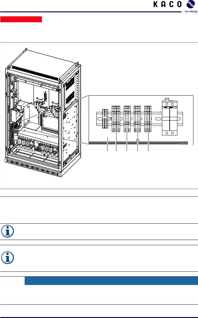
7.6Connecting the interfaces
Overview
1 |
2 |
3 |
4 |
5 |
Figure 17: Interface connections (XP250-HV)
Key
1 |
User interface |
4 |
Analogue user input (UAI) |
2 |
Digital user input/output (UDIO) |
5 |
Remote power control (RPC) for managing grid feed-in |
|
|
|
|
3 |
RS485 |
|
|
NOTE
The digital, analogue, RS485 and Ethernet connections are designed for SELV.
NOTE
›› Use shielded communication cables to improve the resistance of the communication against interferences.
›› Connect the shield to ground potential.
CAUTION
Damage to the inverter due to energized terminals
›› Connect only communication cables to the interface connections. ›› Use the communication cables only for communication signals.
Page 26 |
Operating Instructions Powador XP200-HV TL, XP250-HV TL, XP350-HV TL_EN |

Installation

 Electrician
7.6.1Connecting the digital input/output
-UDIO |
|
|
|
|
|
|
|
|
|
|
|
|
|
|
|
|
|
|
|
|
|
|
|
|
|
1b |
2b |
3b |
4b |
5b |
|
|
|
|
|
230 V P |
|
|
|
|
|
|
|
|
|
|
|
|
|
|
|
|
|
|
|
|
|
|
|
|
|
|
|
|
|
|
Terminal |
Terminal |
Specification Wire cross-section, |
||
|
|
|
|
|
|
|
|
||||
|
|
|
|
|
|
|
|
number |
designation |
|
max. |
|
|
1a |
2a |
3a |
4a |
5a |
|
||||
|
|
|
|
|
|
|
|||||
|
|
|
1a |
UDI1 N |
Potential-free |
AWG 20 |
|||||
|
|
|
|
|
|
|
|
||||
230 V N |
|
|
|
|
|
|
|
|
|
input contact, |
|
|
|
|
|
|
|
|
1b |
UDI1 P |
(0.75 mm2) |
||
|
|
|
|
|
|
|
max. 27 V, 27 mA |
||||
|
|
|
|
|
|
|
|
|
|
|
|
|
|
|
|
|
|
|
|
|
|
||
Figure 18: UDIO connection |
|
Table 7: Connections for digital input |
|
||||||||
7.6.1.1S0 input
-UDIO
GND
Signal transceiver
1b 2b |
3b |
4b |
5b |
1a 2a |
3a |
4a |
5a |
Current limiting resistor, 4.7 kΩ
24 V
Figure 19: Connection for S0 input
Terminal |
Terminal |
Specification |
Wire cross-section, |
|
number |
designation |
|
max. |
|
|
|
|
|
|
2a |
S0in N |
Max. 27 V, |
AWG 20 |
|
|
|
27 mA |
(0.75 mm2) |
|
2b |
S0in P |
|||
|
|
|||
|
|
|
|
Table 8: Connections for S0 input
Operating Instructions Powador XP200-HV TL, XP250-HV TL, XP350-HV TL_EN |
Page 27 |
Loading...