


Powador
XP100-HV
Operating Instructions
English Version
GM00201c

1 |
General Notes............................................ |
4 |
1.1 |
About this documentation ................................. |
4 |
1.2 |
Name plate ............................................................... |
5 |
1.3 |
Intended use ............................................................ |
6 |
1.4 |
Safety instructions ................................................. |
6 |
2 |
Service........................................................ |
7 |
3 |
Unit Description........................................ |
8 |
3.1 |
Technical Data ......................................................... |
8 |
3.2 |
Dimensions............................................................. |
10 |
3.3 |
Components inside the inverter...................... |
11 |
4 |
Transportation and Delivery .................. |
13 |
4.1 |
Delivery..................................................................... |
13 |
4.2 |
Transportation........................................................ |
13 |
5 |
Installation/Start-up................................ |
14 |
5.1Transporting the unit to the
|
installation location ............................................ |
14 |
5.2 |
Selecting the installation location ................. |
14 |
5.3 |
Electrical connection .......................................... |
16 |
5.4 |
Start-up .................................................................... |
20 |
5.5 |
Operation................................................................ |
22 |
5.6 |
User interface (MMI) ........................................... |
25 |
5.7 |
MMI menu structure and details .................... |
26 |
5.8 |
MMI main menu.................................................... |
27 |
5.9 |
MMI submenus...................................................... |
29 |
6 |
Faults and Warnings ............................... |
40 |
6.1 |
Warnings................................................................. |
40 |
6.2 |
Faults......................................................................... |
41 |
6.3 |
Error code................................................................ |
42 |
Operating Instructions
- English Version -
Powador XP100-HV
General Instructions
for Installers and Operators
7 |
Maintenance/Cleaning ........................... |
48 |
7.1 |
Maintenance intervals ....................................... |
49 |
7.2 |
Cleaning and replacing the fans..................... |
50 |
8 |
Parameter ................................................. |
51 |
8.1 |
PV Array Parameters............................................ |
51 |
8.2 |
Inverter Parameters............................................. |
52 |
8.3 |
Grid Parameters .................................................... |
53 |
8.4 |
Time Parameters................................................... |
63 |
8.5 |
Digital Parameters ............................................... |
63 |
8.6 |
Analog Parameters ............................................. |
64 |
8.7 |
Controller Parameters......................................... |
65 |
9 |
User interface .......................................... |
81 |
9.1 |
External TO AC voltage supply........................ |
82 |
9.2 |
Digital input/output............................................ |
82 |
9.3 |
RS485 interface .................................................... |
84 |
9.4 |
Analogue Input .................................................... |
86 |
9.5 |
Remote power control ..................................... |
88 |
10 |
Overview Circuit Diagram...................... |
89 |
11 |
Decommissioning/Dismantling............. |
90 |
12 |
Disposal ................................................... |
91 |
13 |
Appendix ................................................ |
92 |
Operating Instructions Powador XP100-HV |
Page 3 |
General Notes
1General Notes
1.1About this documentation
WARNING
Improper handling of the inverter can be dangerous
›You must read and understand the operating instructions before you can install and use the inverter safely.
1.1.1Other applicable documents
During installation, observe all assembly and installation instructions for components and other parts of the system. These instructions are delivered together with the respective components and other parts of the system.
Some of the documents which are required to register your photovoltaic system and have it approved are included with the operating instructions.
1.1.2Retention of documents
These instructions and other documents must be stored near the system and be available whenever they are needed.
1.1.3Description of safety instructions
DANGER
Imminent danger
Failure to observe this warning will lead directly to serious bodily injury or death.
WARNING
Potential danger
Failure to observe this warning may lead to serious bodily injury or death.
CAUTION
Low-risk hazard
Failure to observe this warning will lead to minor or moderate bodily injury.
ATTENTION
Hazard with risk of property damage
Failure to observe this warning will lead to property damage.
NOTE
Useful information and notes.
Page 4 |
Operating Instructions Powador XP100-HV |

General Notes
1.1.4Symbols used in this document
General danger symbol |
Risk of fire or explosion |
High voltage |
Risk of burns |
1.1.5Description of actions
Action
Perform this action
(Possibly additional actions) The result of your action(s)
1.1.6Abbreviations
MMI |
User interface |
MPP |
Point of the current-voltage diagram of a solar |
|
(Man Machine Interface) |
|
cell at which the maximum amount of power |
|
|
|
can be drawn |
IGBT |
Semiconductor device |
MPPT |
The MPP tracker adjusts the voltage to the |
|
(Insulated Gate Bipolar Transistor) |
|
MPP value. |
DSP |
Digital Signal Processor |
PEBB |
Power electronics module |
|
|
|
(Power Electronics Building Block) |
FPGA |
Integrated circuit for digital technology |
PSIM |
Master control for the interfaces in the unit |
|
(Field Programmable Gate Array) |
|
(PEBB Signal Interface Master) |
SELV |
Safety Extra-Low Voltage |
NVSRAM |
Permanent memory in which fixed parameters |
|
|
|
are stored (Non-Volatile Static Random Access |
|
|
|
Memory) |
AS-i 3 Analog Signal Interface 3
1.2Name plate
The name plate is located on the inside of the left door of the two housing components.
Operating Instructions Powador XP100-HV |
Page 5 |

General Notes
1.3Intended use
The inverter converts the DC voltage generated by the photovoltaic (PV) modules into AC voltage and
feeds this into the power grid. The inverter is built according to the state of the art and recognised safety rules. Nevertheless, improper use may cause lethal hazards for the operator or third parties, or may result
in damage to the unit and other property.
The inverter may be operated only with a permanent connection to the public power grid.
Any other or additional use is not considered the intended use. Examples of unintended use include:
•Mobile use
•Use in rooms where there is a risk of explosion
•Use in rooms where the humidity is higher than 95%
1.4Safety instructions
DANGER
Lethal voltages are still present in the terminals and lines of the inverter even after the inverter has been switched off and disconnected!
Coming into contact with the lines and terminals in the inverter will cause serious injury or death.
Only authorised electricians who are approved by the supply grid operator are allowed to open, install and maintain the inverter.
›Keep all doors and covers closed when the unit is in operation.
›Do not touch the lines and terminals when switching the unit on and off!
The electrician is responsible for observing all existing standards and regulations.
•Above all, be sure to observe standard IEC 60364-7-712:2002, “Requirements for Special Installations or Locations – Solar Photovoltaic (PV) Power Supply Systems”.
•Ensure operational safety by providing for proper earthing, conductor dimensioning and appropriate protection against short circuiting.
•Observe the safety instructions located on the inner sides of the doors.
•Switch off all voltage sources and secure them against being inadvertently switched back on before performing visual inspections and maintenance.
•When taking measurements while the inverter is live:
–Do not touch the electrical connections.
–Remove jewellery from your wrists and fingers.
–Make sure that the testing equipment is in good and safe operating condition.
•Stand on an insulated surface when working on the inverter.
•Generally, the inverter may not be modified.
•Modifications to the surroundings of the inverter must comply with national and local standards.
Page 6 |
Operating Instructions Powador XP100-HV |

Service
2Service
If you need help fixing a technical problem with one of our KACO products, please contact our service hotline. Please have the following information ready so that we can help you quickly and efficiently:
•Inverter type/Serial number
•Error message shown on the display/Description of the fault/Did you notice anything unusual?/ What has already been done to analyse the fault?
•Module type and string circuit
•Date of installation/Start-up report
•Consignment identification/Delivery address/Contact person (with telephone number)
We have prepared a template for complaints. It is located at
http://www.kaco-newenergy.de/en/site/service/kundendienst/index.xml.
Hotlines
|
Technical troubleshooting |
Technical consultation |
||
Inverters (*) |
+49 (0) 7132/3818-660 |
+49 |
(0) |
7132/3818-670 |
|
|
|
|
|
Data logging and accessories |
+49 (0) 7132/3818-680 |
+49 |
(0) |
7132/3818-690 |
|
|
|
|
|
Construction site emergency (*) |
+49 (0) 7132/3818-630 |
|
|
|
Customer helpdesk |
Monday to Friday from 7:30 a.m. to 5:30 p.m. (CET) |
|||
|
|
|
|
|
(*) Also on Saturdays from 8:00 a.m. to 2:00 p.m. (CET)
Operating Instructions Powador XP100-HV |
Page 7 |

Unit Description
3Unit Description
3.1Technical Data
Electrical Data
Input levels
Max. PV generator power |
110 kW |
MPPT range |
450 to 830 V |
|
|
No-load voltage |
A maximum of 1000 V |
|
|
Voltage/current ripple |
< 3 % / < 4 % |
|
|
Max. input current |
245 A |
|
|
Overvoltage protection |
SPD |
|
|
Output levels |
|
|
|
Rated power |
100 kW |
|
|
Max. power |
100 kW |
|
|
Line voltage |
In accordance with country-specific guidelines |
|
|
Output voltage |
3*380 / 400 V (±10%) |
|
|
Rated current |
153 A |
|
|
Max. current |
153 A |
|
|
Rated frequency |
50 / 60 Hz |
|
|
cos phi |
≥ 0.99 at rated power |
|
|
Distortion factor |
< 3 % at rated power |
|
|
Fault signal relay |
Potential-free NO contact, max. 30 V/1 A |
|
|
S0 output |
Open collector output, max. 30 V/50 mA |
|
|
General electrical data |
|
|
|
Max. efficiency |
97.10 % |
|
|
European efficiency |
96.50 % |
|
|
Standby |
< 100 W |
|
|
Grid monitoring |
Compliant with VDEW guidelines |
|
|
Table 1: Electrical data of the inverter |
|
Page 8 |
Operating Instructions Powador XP100-HV |

Unit Description
Mechanical Data
Display |
TFT LCD touchscreen |
Interfaces |
2 RS485 / 1 Ethernet / 1 USB |
|
4 x analogue inputs |
|
1 x digital input |
|
1 x S0 input |
|
1 x digital output |
|
1 x S0 output |
|
|
Memory |
SD card, up to 8 GB |
|
|
Operating temperature range |
-20 °C to +50 °C |
|
|
Storage temperature range |
-20 °C to +70 °C |
|
|
Relative humidity |
0 to 95 % |
|
|
Cooling |
Fan, max. 2590 m³/h |
|
|
Protection rating |
IP 21 (in accordance with DIN EN 60529:2000) |
|
Intended for indoor use only in accordance with IEC |
|
62103:2003 |
|
|
Noise emission |
< 70 dB |
|
|
Housing |
Upright, steel housing |
|
|
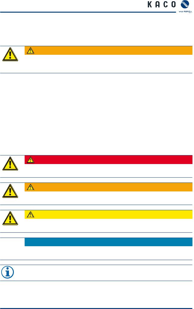
H x W x D |
2120 x 1200 x 870 (mm) |
|
|
Base |
1200 x 780 (mm) |
|
|
Total weight |
1120 kg |
|
|
Table 2: Mechanical data of the inverter |
|
Operating Instructions Powador XP100-HV |
Page 9 |
Unit Description
3.2Dimensions
Figure 1: Dimensions of the inverter [mm]
Figure 2: Dimension of the inverter base [mm]
Page 10 |
Operating Instructions Powador XP100-HV |
Unit Description
3.3Components inside the inverter
20 |
21 |
22 |
1
2
19
3
18 |
|
|
|
|
|
|
|
|
|
|
|
|
|
|
|
|
|
|
|
|
|
|
|
|
|
|
|
|
|
|
|
17 |
|
|
|
|
|
|
|
|
|
|
|
|
|
|
4 |
|
|
|
|
|
|
|
|
|
|
|
|
|
|
||
16 |
|
|
|
|
|
|
|
|
|
|
|
|
|
|
5 |
|
|
|
|
|
|
|
|
|
|
|
|
|
|
||
|
|
|
|
|
|
|
|
|
|
|
|
|
|
||
|
|
|
|
|
|
|
|
|
|
|
|
|
|
|
6 |
|
|
|
|
|
|
|
|
|
|
|
|
|
|
|
|
15 |
|
|
|
|
|
|
|
|
|
|
|
7 |
|||
|
|
|
|
|
|
|
|
|
|
|
|||||
|
|
|
|
|
|
|
|
|
|
|
|
|
|
8 |
|
|
|
|
|
|
|
|
|
|
|
|
|
|
|
||
14 |
|
|
|
|
|
|
|
|
|
|
|
|
|
|
|
|
|
|
|
|
|
|
|
|
|
|
|
9 |
|||
|
|
|
|
|
|
|
|
|
|
|
|
|
|||
|
|
|
|
|
|||||||||||
13 |
|
|
|
|
|
|
|
|
|
|
|
|
10 |
||
|
|
|
|
||||||||||||
|
|
|
|
|
|
|
|
|
|
|
|
|
|||
|
|
|
|
|
|
|
|
|
|
|
|
|
|
|
11 |
|
|
|
|
|
|
|
|
|
|
|
|
|
|
|
|
|
|
|
|
|
|
|
|
|
|
|
|
|
|
|
12 |
|
|
|
|
|
|
|
|
|
|
|
|
|
|
|
|
Figure 3: Components inside the inverter (front)
Key
1 |
Door sensor |
12 |
Grounding busbar |
2 |
AC bus |
13 |
DC port |
3 |
Control system |
14 |
DC fuse |
|
|
|
|
4 |
AC EMC Filter |
15 |
DC surge protection |
|
|
|
|
5 |
AC switch |
16 |
DC breaker |
6 |
MCB and surge protection for control power |
17 |
Ground fault detection |
|
|
|
|
7 |
MCB for surge protection |
18 |
MCB for measurement circuit |
|
|
|
|
8 |
AC contactor |
19 |
PEBB |
9 |
AC port |
20 |
DC fan |
|
|
|
|
10 |
Terminals for user connection |
21 |
24V voltage supply |
|
|
|
|
11 |
AC surge protection |
22 |
MCB for PSU |
Operating Instructions Powador XP100-HV |
Page 11 |

Unit Description
7 1
6
2
5
3
4
Figure 4: Components inside the inverter (rear)
Key
1 |
Door sensor |
5 |
LC filter capacitor |
2 |
LC filter (line choke) |
6 |
FRT module |
|
|
|
|
3 |
Transformer |
7 |
AC enclosure fan |
4 |
Grounding busbar |
|
|
|
|
|
|
Page 12 |
Operating Instructions Powador XP100-HV |
Transportation and Delivery
4Transportation and Delivery
4.1Delivery
The inverters leave our factory in proper electrical and mechanical condition. Special packaging ensures that they are transported safely. The shipping company is responsible for any damage that occurs during transportation.
4.1.1Scope of delivery
•Powador XP100-HV
•Documentation
Check your delivery
Inspect the inverter thoroughly.
Notify the shipping company immediately if you discover any damage to the packaging which indicates that the inverter may have been damaged or if you discover any visible damage to the inverter.
Send the damage report to the shipping company right away. It must be received by them within six days following receipt of the inverter. We will be glad to help you, if necessary.
4.2Transportation
The inverter should be shipped using the original packaging to ensure that it is transported safely. The inverter cabinet is delivered on a euro pallet.
CAUTION
Impact hazard, risk of breakage to the inverter
The centre of gravity is located in the upper part of the inverter. › Transport the inverter in an upright position.
Operating Instructions Powador XP100-HV |
Page 13 |
Installation/Start-up
5Installation/Start-up
5.1Transporting the unit to the installation location
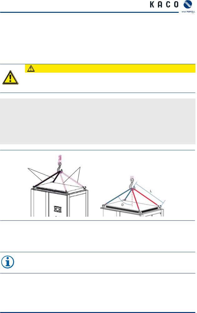
Once it has arrived at the installation location, the inverter may be transported using the designated eyebolts only. These are located on the top of the inverter housing (figure 5).
CAUTION
Impact hazard, risk of breakage to the inverter
The centre of gravity is located in the upper part of the inverter.
› Transport the inverter in an upright position.
Transporting the inverter
Transport the inverter in an upright position.
Attach a rope (1) to the two eyebolts on the right.
Attach a second rope (2) to the two eyebolts on the left.
Attach both ropes to a hook, making sure that the ropes do not cross each other.
Position the hook at the middle of the unit.
2 |
1 |
› Angle ( D ) - 50°
› Length ( L ) - 950mm
Figure 5: Transporting the unit at the installation location
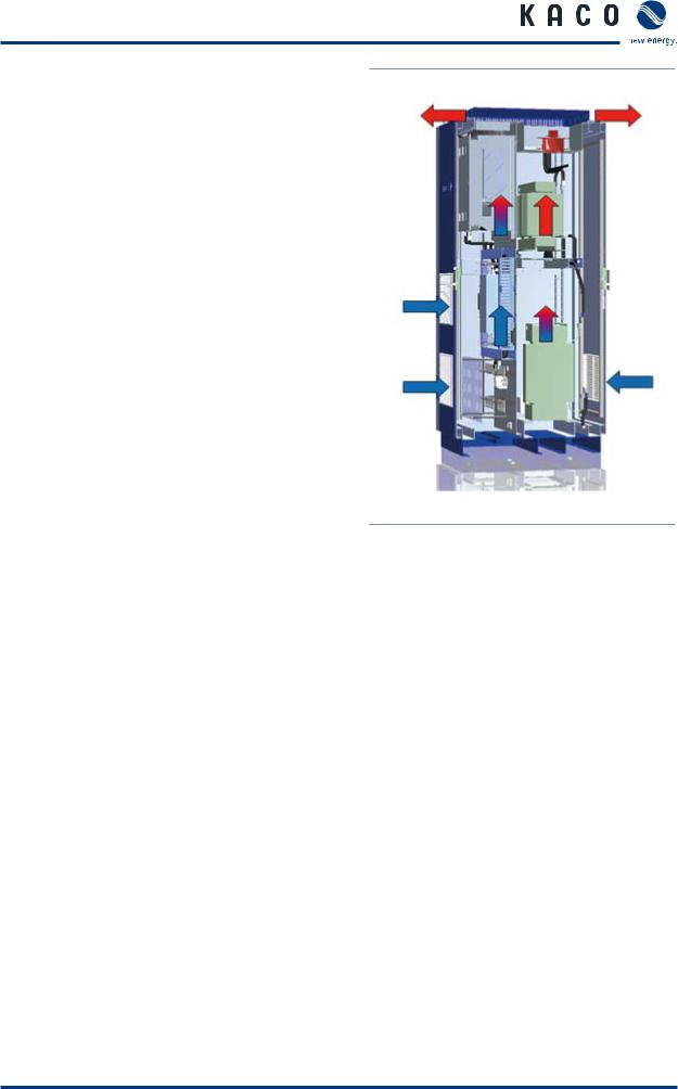
5.2Selecting the installation location
NOTE
The maximum flow rate of the cooling air is 2590 m³ per hour (figure 6).
Please keep this value in mind when you select the installation location.
Page 14 |
Operating Instructions Powador XP100-HV |
Installation/Start-up
Floor
•Must have adequate load-bearing capacity
•The building material must meet the requirements of building material class B1 (“Flameresistant Building Materials”, in accordance with DIN EN 13501-1)
Room
•Should be as dry as possible
•Must be indoors (IP 21)
•The installation location must be climate-con- trolled in order to dissipate the waste heat
•Additional ventilation should be provided, if necessary
•Do not install in a room where there is a risk of explosion
Clearance between walls and ceiling
•Must be accessible for installation and maintenance
•Air circulation may not be blocked (figure 6)
•You do not have to provide for clearance on the sides or to the rear of the unit
•Minimum clearance between unit and ceiling: 40 cm
Figure 6: Ventilation for the inverter
Operating Instructions Powador XP100-HV |
Page 15 |

Installation/Start-up
5.3Electrical connection
DANGER
Lethal voltages are still present in the terminals and lines of the inverter even after the inverter has been switched off and disconnected!
Coming into contact with the lines and terminals in the inverter will cause serious injury or death.
Only authorised electricians who are approved by the supply grid operator may open, install and maintain the inverter.
›Use extreme caution when working on the unit.
›Disconnect the AC and DC sides.
›Secure them against being inadvertently switched back on.
›Connect the inverter only after the aforementioned steps have been taken.
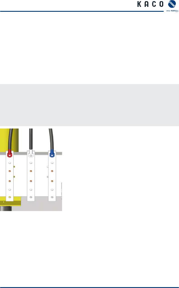
5.3.1Protective earth connection
Connect the PE busbars
The PE (protective earth) busbars are located
on the left and right sides of the inverter cabinets (figure 7).
Connect the wires for both PE busbars.
Earth the inverter
Determine the lay-out of the permanent wiring.
Secure the protective earths (tightening torque for PE terminals: 30 Nm).
Do not use plug connections.
Check whether all connected cables are securely attached and protected from mechanical forces.
Attach the Plexiglas cover.
Figure 7: PE busbar
Page 16 |
Operating Instructions Powador XP100-HV |
Installation/Start-up
5.3.2Connecting to the external transformer (AC connection)
The inverter is connected to the power grid using a 3-phase connection. The connection for the power grid is located in the right side of the housing, at the bottom (figure 8).
Connection data
Max. cable diameter |
300 mm² |
Tightening torque for AC terminal connections |
43 Nm |
Cable Lug hole size |
12 mm ~ 14 mm |
Connect the cables
Each cable corresponds to one phase.
Guide the cables through the opening.
Be sure to connect each of the cables to the correct terminal.
Screw down the cables.
Check to make sure that all of the cables are securely attached.
Figure 8: AC connection
Operating Instructions Powador XP100-HV |
Page 17 |

Installation/Start-up
5.3.3Connection for the PV generator (DC connection)
The DC connection is located in the left side of the housing, at the bottom (figure 9).
Connection data
Tightening torque for DC terminal connections |
25 Nm |
DC input terminal |
+4, -4 |
DC Fuse |
+1(300A), -1(300A) |
Cable Lug hole size |
10 mm ~ 12 mm |
DANGER
Lethal voltages in the PV system
Lethal voltages are present in the PV system.
› Make absolutely sure that the plus and minus poles are properly insulated.
Connect the cables
Each cable corresponds to a specific pole.
Connect the cables to the poles. Make sure the polarity is correct.
Screw down the cables.
Check to make sure that all of the cables and seals are securely attached.
Figure 9: DC connection
NOTE
Use only the optional earthing kit to earth the PV generator.
Page 18 |
Operating Instructions Powador XP100-HV |

Installation/Start-up
5.3.4Connecting the external voltage supply
The external voltage supply supplies the MMI, fans, measurement equipment, etc. The inverter will not work without this connection.
Connect the external voltage supply (figure 10)
The connection for the additional power supply is located in the right side of the inverter housing.
Connect the additional power supply to the terminals marked “TO” using single-phase 230 V.
3
1, 2
4
Figure 10: Connecting the external voltage supply
Key
1 |
230 V L |
3 |
TO (connection for auxiliary power supply) |
2 |
230 V N |
4 |
User interface |
|
|
|
|
Operating Instructions Powador XP100-HV |
Page 19 |

Installation/Start-up
5.4Start-up
The circuit breakers must be switched on to start up the inverter. The circuit breakers switch on the control circuits.
DANGER
Lethal voltages are still present in the terminals and lines of the inverter even after the inverter has been switched off and disconnected!
Coming into contact with the lines and terminals in the inverter will cause serious injury or death.
Only authorised electricians who are approved by the supply grid operator may open, install and maintain the inverter.
›Keep all doors and covers closed when the unit is in operation.
›Do not touch the lines and terminals when switching the unit on and off!
Switch on the circuit breakers (figure 11)
Circuit breaker |
Check |
Action |
1. Circuit breakers CB30 to 35 |
ON |
Proceed to Step 2 |
|
|
|
|
OFF |
Switch on, |
|
|
then proceed to Step 2 |
|
|
|
2. Circuit breakers MCB21 and MCB24 |
ON |
Proceed to Step 3 |
|
|
|
|
OFF |
Switch on, |
|
|
then proceed to Step 3 |
|
|
|
3. External circuit breaker for line voltage |
|
Switch on |
|
|
Start up the inverter |
|
|
|
Page 20 |
Operating Instructions Powador XP100-HV |
Installation/Start-up
2
1
Figure 11: Cabinet (interior view)
Key
1Circuit breakers CB30 to 35 (PV side)
2Circuit breakers MCB21 and MCB24 (grid side)
When voltage is present at the inverter, it can be started up. Use the MMI interface screen (located in the left side of the housing) to start up the inverter.
The inverter begins operation in a specified sequence. For more information, see section 5.1 (“Transporting the unit to the installation location”) on page 15.
If a fault occurs, the inverter cannot begin operation. For more information on faults, see section 6 (“Faults and Warnings”) on page 41. For more information on “Fault reset”, see section 9 (“User Interface”) on page 82.
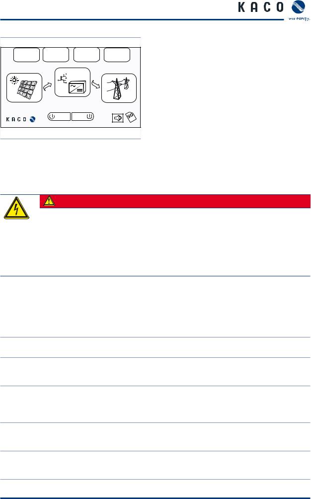
Start up the inverter (figure 12)
Display |
Check |
Action |
Error message on the MMI screen |
NO |
Select the ON button |
|
YES |
Reset using “Fault reset" |
|
|
Select the ON button |
|
|
|
NOTE
If the fault cannot be reset using “Fault reset”, please contact our service department.
Operating Instructions Powador XP100-HV |
Page 21 |
Installation/Start-up
|
|
|
|
Fault |
History |
Statistics |
Setup |
79.0kW |
|
45.0°C |
75.8kW |
|
|
|
|
701.0V |
|
|
380.0V |
|
ON |
OFF |
|
|
Date/Time |
|
|
Figure 12: MMI screen
5.5Operation
DANGER
Lethal voltages are still present in the terminals and lines of the inverter even after the inverter has been switched off and disconnected!
Coming into contact with the lines and terminals in the inverter will cause serious injury or death.
Only authorised electricians who are approved by the supply grid operator may open, install and maintain the inverter.
›Keep all doors and covers closed when the unit is in operation.
›Do not touch the lines and terminals when switching the unit on and off!
5.5.1Operating states
The Inverter has eight operating states. The explanations about each state are below.
Disconnected (default) |
Before operation has commenced the inverter is in the disconnected state. In |
|
this state, the inverter is totally isolated from the PV array and the utility grid. |
||
|
When the inverter is in the "Disconnected" state, the ‘Inverter On’ button on Connecting to the PV array the GUI is selected and the PV voltage is kept above 400V for 5 seconds, the
system turns on the PV Array side contactor (PV_MC).
When the inverter is in the “Connecting to PV Array” state and the PV voltage is
Connecting to Grid kept above the value of “MPPT V Start” parameter during the time set by “MPPT T start” parameter, the contactor on the grid side is turned on. The inverter
keeps this state for 8 seconds.
The inverter calculates the MPPT start voltage which is product of measure- Initializing MPP ment of PV voltage and the parameter “MPP Factor”. After 5 seconds, the
inverter system enters into the "MPP start" state.
In this state, the inverter controls the PV voltage. Reference of the PV voltage is MPP start determined by MPPT start voltage which is calculated at “Initializing MPP”
state.
Table 3: Operating states
Page 22 |
Operating Instructions Powador XP100-HV |

Installation/Start-up
If the PV voltage approximates the MPP start voltage (value of “MPPT V Start” parameter), the MPPT will start. The inverter follows the MPP target value auto- MPPT matically, which is varied by irradiance values. If the MPP target value is out of the allowable MPPT range ([MPP start voltage – MPP Range lower] ~ [MPP start voltage + MPP range upper]), the system will return to the “Initializing MPP”
state and will recalculate the MPPT start voltage.
When the “OFF” button in the GUI is selected, the PV Array side contactor and
System stop the Grid side contactor are turned off and the system stops. If the output power of inverter is kept below value of “MPPT P stop” parameter during time of
“MPPT T stop” parameter, connection to the grid is terminated.
If a fault occurs during operation, the system stops. The system resets the fault and tries to remove the fault. In the case that system removes a fault successfully, system restarts all by itself. The system tries to remove the fault at inter-
Fault vals of “MPPT Start” parameter since the last try until trial count reaches to the number set in an “Auto Fault Reset Count” parameter. After the number reaches to the “Auto Fault Reset Count” parameter, the system will log an error and the system will not try to restart.
Table 3: Operating states
Operating Instructions Powador XP100-HV |
Page 23 |
Installation/Start-up
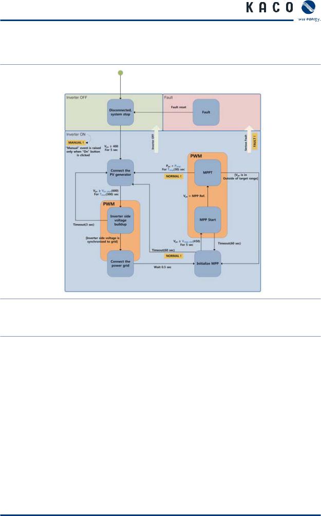
5.5.2Overview of operating states
Figure 13: Overview of operating states
Key
MPPT |
Maximum Power Point Tracker |
Tstart |
Minimum time for which Vpv must be greater |
than Vpv_start |
|||
Vpv |
Voltage in the PV generator |
MPP ref. |
PV voltage reference |
VMPP min |
Minimum voltage of the MPP |
Ppv |
PV power |
Vpv_start |
Starting voltage in the PV generator |
Pstop |
Power level at which the feed-in is inter- |
rupted |
Page 24 |
Operating Instructions Powador XP100-HV |

Installation/Start-up
5.6User interface (MMI)
The MMI has a graphic interface which you use to monitor and control the inverter. The MMI has the following functional features:
•The LCD screen displays the operating states, along with voltages, currents, frequencies, temperatures, output powers, status of errors/warning messages, and events. Pressing the MMI touch screen switches on the LCD backlight. If the display is not activated within five minutes, the LCD backlight switches automatically off.
•Touch screen for navigating through the menus SD card: the MMI continually records data to the SD card. When recording once every 10 minutes (around the clock), the maximum amount of data per year is 360 KB. When the SD card is full, the oldest data is overwritten.
•Configuration of country-specific settings (power grid standard, maximum/minimum voltage/ frequency)
•Ethernet interface for monitoring and service, network connection for remote use
•RS485 interface for logging and transferring data
•USB interface for connecting external units (e.g. laptop computer)
1 |
|
|
|
|
2 |
|
|
4 |
|
|
|
5 |
|
|
3 |
|
|
|
|
|
|
|
6 |
8 |
|
|
|
7 |
|
|
|
|
|
|
Figure 14: Front of the MMI |
|
Figure 15: Rear of the MMI |
|
|
Key |
|
|
|
|
|
|
|
|
|
1 |
Protective cover |
5 |
Ethernet interface |
|
|
|
|
|
|
2 |
MMI touchscreen, LCD |
6 |
RS232 interface (internal interface) |
|
3 |
USB interface |
7 |
RS485 interface |
|
|
|
|
|
|
4 |
Power connection |
8 |
SD card |
|
|
|
|
|
|
Operating Instructions Powador XP100-HV |
Page 25 |
Installation/Start-up
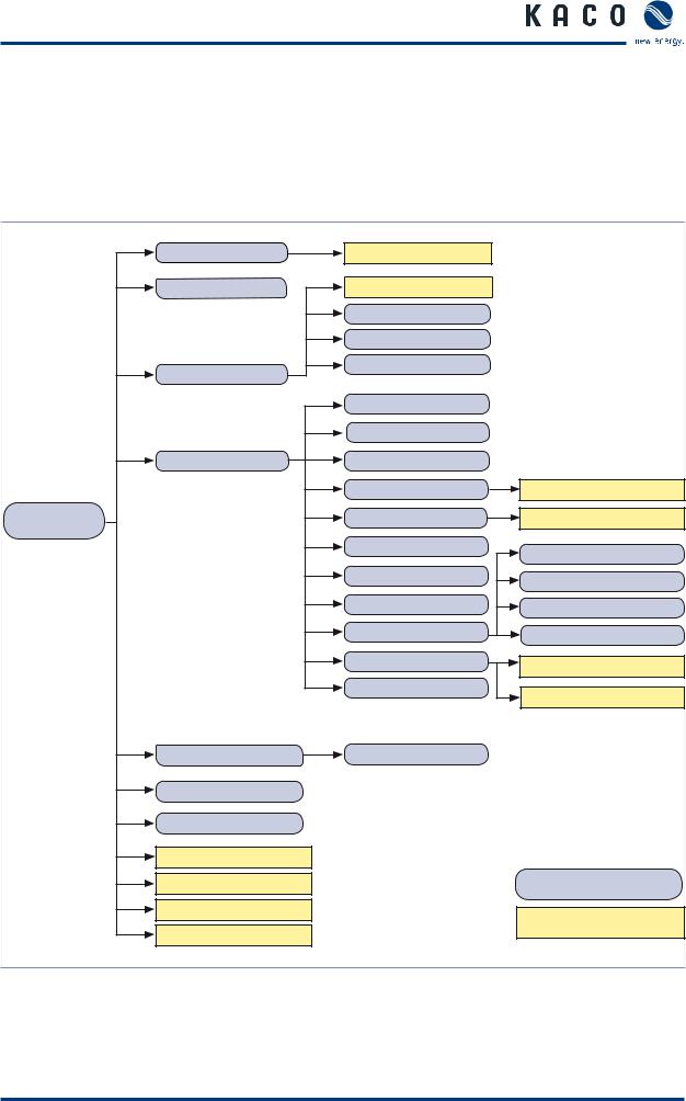
5.7MMI menu structure and details
The MMI menu is structured hierarchically (figure 16).
•The blue areas (rounded corners) are functions that are activated by pressing a button.
•The yellow areas (square corners) are windows with additional content, such as submenus, measured values and buttons. These functions are reserved for authorised electricians.
Fault |
Fault Reset |
|
History |
Calendar |
|
|
|
|
|
Day |
|
|
Month |
|
Statistics |
Year |
|
|
|
|
|
Date/Time |
|
|
Digital |
|
Setup |
Analog |
|
|
Recording |
Statistics Reset |
|
|
|
|
RS485 |
Setup Powador-go address |
Main menue |
|
|
|
|
|
|
Language & Country |
PV array |
|
|
|
|
User configuration |
Inverter |
|
|
|
|
Network |
Grid |
|
|
|
|
Service |
Cos-phi |
|
Software Upgrade |
MMI |
|
Information |
C6x |
|
|
|
PV generator |
String monitoring |
|
Inverter |
|
|
Grid |
|
|
Start Inverter |
|
|
Stop Inverter |
|
Blue: |
|
|
functions |
Speaker OFF |
|
Yellow: |
|
|
|
Remove SD card safely |
|
additional content |
|
|
Figure 16: MMI menu structure
Page 26 |
Operating Instructions Powador XP100-HV |
Installation/Start-up
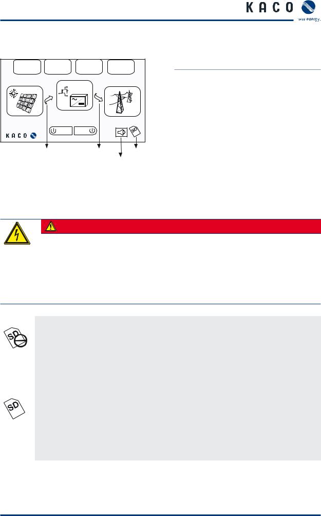
5.8MMI main menu
|
|
|
|
Fault |
History |
Statistics |
Setup |
79.0kW |
|
45.0°C |
75.8kW |
|
|
|
|
701.0V |
|
|
380.0V |
|
ON |
OFF |
|
|
Date/Time |
|
|
Circuit breaker |
Circuit breakers |
SD card |
|
CB10 |
|
MC21 + CB20 |
Speaker |
Figure 17: Display when the MMI starts up
Displayed button colours
Colour |
Meaning |
Green |
Normal operation |
|
|
|
Fault |
Red |
(not for switches CB10, |
|
MC21 and CB20) |
|
|
Grey |
Not in use |
|
|
5.8.1Changing the SD card, status display
DANGER
Lethal voltages are still present in the terminals and lines of the inverter even after the inverter has been switched off and disconnected!
Coming into contact with the lines and terminals in the inverter will cause serious injury or death.
Only authorised electricians who are approved by the supply grid operator may open, install and maintain the inverter.
›Keep all doors and covers closed when the unit is in operation.
›Do not touch the lines and terminals when switching the unit on and off!
Insert the SD card
“No SD in slot” icon
Open the inverter. The inverter shuts down.
Slide the SD card into the slot until it locks into place.
Close the inverter.
Press the ON button. The inverter starts up.
“SD card in slot” icon
The inverter checks the card. If the SD card was detected, the “SD card in slot” icon appears in the lower right-hand corner of the display
Press the SD card icon
Wait until the SAFE icon is displayed.
Operating Instructions Powador XP100-HV |
Page 27 |
Installation/Start-up
Remove the SD card
SAFE “Data was saved to the SD card” icon
You can remove the SD card. The icon is displayed for one minute.
Open the inverter.
Remove the SD card by gently pressing and then releasing it. The SD card will pop out slightly. You can now remove it.
Close the inverter and start it up.
NOTE
Do not remove the SD card until the SAFE icon is displayed so that it will be detected by the MMI when you reinsert it.
5.8.2Status display for speaker
Audible signal when you press the LCD screen
No signal
5.8.3Using the main menu
Press button |
Result/Function |
PV generator |
The measured values for the PV generator are displayed (figure 18) |
Inverter |
The measured values for the inverter are displayed (figure 19) |
Power grid (AC connection) |
The measured values for the power grid are displayed (figure 20) |
ON |
Switches on the inverter |
OFF |
Switches off the inverter |
Speaker |
Switches speaker on/off |
Page 28 |
Operating Instructions Powador XP100-HV |
Installation/Start-up
5.9MMI submenus
5.9.1PV generator
Return to next higher level
String monitoring is activated 
PV generator |
Strings |
|
Power (kW) |
Voltage (V) |
Current (A) Isolation R (kΩ) |
|
0.0 |
0.0 |
0.0 |
0.0 |
Cell Temp. (°C) |
Irr. (W/m2) |
Ambi.Temp. (°C) |
Wind(m/s) |
0.0 |
0.0 |
0.0 |
0.0 |
Figure 18: “PV generator” screen
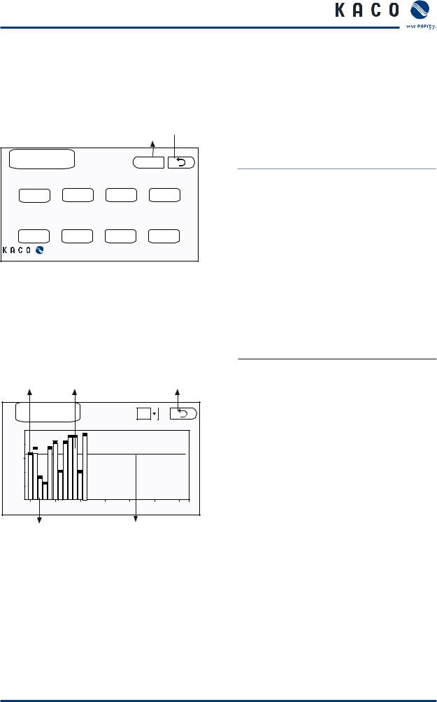
5.9.2String monitoring
Buttons
Display |
Meaning |
Measured |
Current measured values for |
values |
the PV generator |
|
|
Strings |
String monitoring is activated |
|
|
Changes to the configuration for the current sensors first become effective after five minutes.
Magenta dots: |
Yellow bars: |
|
|
Actual current |
Average current values, |
Return to the |
|
values |
faulty channel |
||
previous level |
|||
|
|
|
Strings |
|
|
Page : |
|
|
|
|
|
|
|
||
|
|
|
|
|
|
|
12 |
|
|
|
|
|
|
9.6 |
|
|
|
|
|
|
7.2 |
|
|
|
|
|
|
4.8 |
|
|
|
|
|
|
2.4 |
|
|
|
|
|
|
0 |
5 |
|
15 |
20 |
|
|
0 |
10 |
25 |
30 |
Green bars: |
Light blue line: |
Average current values, |
Average of all channels |
functioning channel |
|
Figure 19: “String monitoring” screen
Current |
Only current actual values are |
actual values |
displayed during the first five |
|
minutes after the function has |
|
been activated. |
|
|
Average |
The actual values for the last |
current |
five minutes are recorded |
values of the |
(sampling period: every 30 |
channels |
seconds). |
Average of |
Average of all current values |
all current |
(channels) |
values |
|
(channels) |
|
|
|
If the average of one channel deviates from the average of all channels by more than the specified range of tolerance and if this persists for longer than a specified delay period, this channel is assumed to be defective.
Operating Instructions Powador XP100-HV |
Page 29 |
 Loading...