


blueplanet
5.0 TL3 | 6.5 TL3
7.5 TL3 | 9.0 TL3
Operating Manual
English translation of German original

Contents |
|
|
1 |
General information ................................. |
4 |
1.1 |
About this document............................................ |
4 |
1.2 |
Layout of Instructions........................................... |
4 |
2 |
Safety ......................................................... |
5 |
2.1 |
Proper use................................................................. |
6 |
2.2 |
Protection features ................................................ |
6 |
2.3 |
Trademark................................................................. |
6 |
2.4 |
Additional information......................................... |
6 |
3 |
Description ................................................ |
7 |
3.1 |
Mode of Operation ................................................ |
7 |
3.2 |
Diagram .................................................................... |
7 |
4 |
Technical Data ......................................... |
10 |
4.1 |
Electrical Data........................................................ |
10 |
4.2 |
Mechanical data..................................................... |
11 |
5 |
Transportation and Delivery................... |
12 |
5.1 |
Delivery..................................................................... |
12 |
5.2 |
Transportation........................................................ |
12 |
6 |
Mounting .................................................. |
13 |
6.1 |
Unpacking............................................................... |
15 |
6.2 |
Mounting................................................................. |
16 |
7 |
Installation................................................ |
17 |
7.1 |
Opening the connection area........................... |
17 |
7.2 |
Configure connections....................................... |
18 |
7.3 |
Preparing the electrical connection.............. |
20 |
7.4 |
Connect the device to the power grid.......... |
20 |
7.5 |
Connect PV generator to device...................... |
21 |
7.6 |
Grounding the housing ..................................... |
24 |
Operating Manual |
EN |
|
for Installation Engineers and Operators
7.7 |
Connecting the interfaces................................. |
25 |
7.8 |
Sealing the connection area ............................ |
28 |
7.9 |
Switching on the device .................................... |
28 |
8 |
Configuration and Operation................. |
29 |
8.1 |
Controls.................................................................... |
29 |
8.2 |
Initial start-up ........................................................ |
32 |
8.3 |
Menu structure...................................................... |
33 |
8.4 |
Monitor device ...................................................... |
41 |
8.5 |
Performing a software update ........................ |
42 |
9 |
Maintenance/Troubleshooting .............. |
43 |
9.1 |
Visual inspection................................................... |
43 |
9.2 |
Cleaning the device............................................ |
44 |
9.3Shutting down for maintenance and
|
troubleshooting................................................... |
44 |
9.4 |
Replacing or cleaning the fans....................... |
44 |
9.5 |
Disconnect connections. ................................... |
45 |
9.6 |
Faults......................................................................... |
47 |
9.7Messages on the display
|
and the "Fault" LED............................................. |
49 |
10 |
Service...................................................... |
52 |
11 |
Shutdown/Disassembly.......................... |
53 |
11.1 |
Shutdown................................................................ |
53 |
11.2 |
Uninstallation ........................................................ |
54 |
11.3 |
Disassembly ........................................................... |
54 |
12 |
Disposal ................................................... |
54 |
13 |
EU Declaration of Conformity ................ |
55 |
Operating Manual KACO blueplanet 5.0TL3 - 9.0TL3 |
Page 3 |

General information
EN |
1 |
General information |
||
|
|
|
|
|
|
1.1 |
About this document |
||
|
||||
|
|
|
|
|
|
|
|
|
WARNING |
|
|
|
|
Improper handling of the device can be hazardous |
|
|
|
|
› You must read and understand the operating instructions so that you can install and use the |
|
|
|
|
device safely. |
|
|
|
|
|
|
1.1.1 |
Other applicable documents |
||
During installation, observe all assembly and installation instructions for components and other parts of the system. These instructions also apply to the equipment, related components and other parts of the system.
Some of the documents which are required for the registration and approval of your photovoltaic (PV) system are included with the operating instructions.
1.1.2Storing the documents
These instructions and other documents must be stored near the system and be available at all times.
1.2Layout of Instructions
1.2.1Symbols used
General hazard |
Risk of fire or explosion |
High voltage |
Risk of burns |
Authorised electrician |
Only authorised electricians are permitted to carry out tasks indicated with this |
symbol. |
|
1.2.2Safety warnings symbols guide
DANGER
High risk
Failure to observe this warning will lead directly to serious bodily injury or death.
WARNING
Potential risk
Failure to observe this warning may lead to serious bodily injury or death.
CAUTION
Low-risk hazard
Failure to observe this warning will lead to minor or moderate bodily injury.
CAUTION
Risk of damage to property
Failure to observe this warning will lead to property damage.
Page 4 |
Operating Manual KACO blueplanet 5.0TL3 - 9.0TL3 |
Safety
1.2.3Additional information symbols
|
NOTE |
|
Useful information and notes |
|
|
|
|
EN |
Country-specific function |
|
Functions restricted to one or more countries are labelled with country codes in accordance with |
|
ISO 3166-1. |
|
|
1.2.4Instructions symbols guide
Instructions
Prerequisites before carrying out the following instructions
Carry out step.
(Additional steps, if applicable) » Result of the step(s) (optional)
EN
1.2.5Target group
All activities described in the document may only be carried out by specially trained personnel with the following qualifications:
•Knowledge about functioning and operation of an inverter
•Training in the handling of hazards and risks during the installation and operation of electrical devices and systems
•Education concerning the installation and startup of electrical devices and systems
•Knowledge of applicable standards and directives
•Knowledge and adherence to this document with all safety notices.
2Safety
DANGER
Lethal voltages are still present in the terminals and cables of the inverter even after the inverter has been switched off and disconnected.
Severe injuries or death if the cables and/or terminals in the inverter are touched.
The inverter is only permitted to be opened and serviced by an authorised electrician.
›Keep the inverter closed when the unit is in operation.
›Do not make any modifications to the inverter.
The electrician is responsible for observing all existing standards and regulations.
•Keep unauthorised persons away from the inverter and PV system.
•In particular, be sure to observe the standard IEC-60364-7-712:2002 "Requirements for special installations or locations – solar photovoltaic (PV) power supply systems".
•Ensure operational safety by providing proper grounding, conductor dimensioning and appropriate protection against short circuiting.
•Observe all safety instructions on the inverter and in these operating instructions.
•Switch off all voltage sources and secure them against being inadvertently switched back on before performing visual inspections and maintenance.
Operating Manual KACO blueplanet 5.0TL3 - 9.0TL3 |
Page 5 |

Safety
EN |
• When taking measurements while the inverter is live: |
|
– |
Do not touch the electrical connections. |
|
|
– Remove all jewellery from your wrists and fingers. |
|
|
||
|
– |
Ensure that the testing equipment is in safe operating condition. |
• Stand on an insulated surface when working on the inverter.
• Modifications to the surroundings of the inverter must comply with the applicable national and local standards.
• When working on the PV generator, it is also necessary to switch off the DC voltage with the DC isolator switch in addition to disconnecting the PV generator from the grid.
2.1 Proper use
The inverter converts the DC voltage generated by the PV modules into AC voltage and feeds it into the grid. The inverter is built according to the latest technological standards and safety regulations. Nevertheless, improper use may cause lethal hazards for the operator or third parties, or may result in damage to the unit and other property.
Operate the inverter only with a permanent connection to the public power grid.
Any other or additional use of the device shall be regarded as improper. This includes:
• Mobile use,
• Use in potentially explosive atmospheres,
• Operation outside the specifications intended by the manufacturer,
• Islanding operation.
2.2Protection features
The following monitoring and protective functions are integrated into Powador inverters:
•Overvoltage conductors/varistors to protect the power semiconductors from high-energy transients on the grid and generator side
•Temperature monitoring of the heat sink
•EMC filters to protect the inverter from high-frequency grid interference
•Grid-side grounded varistors to protect the inverter against burst and surge pulses
•Islanding detection according to the current standards.
2.3Trademark
The software of the inverter uses the MD5 Message Digest algorithm of RSA Data Security, Inc.
The devices uses the open source operating system FreeRTOS 7.00
2.4Additional information
NOTE
The EU Declaration of Conformity can be found in the appendix. For information on grid coupling, grid protection and safety parameters along with more detailed instructions see our web site at http://www.kaco-newenergy.de/.
Page 6 |
Operating Manual KACO blueplanet 5.0TL3 - 9.0TL3 |
Description
3 |
Description |
|
|
EN |
|||
|
|
3.1Mode of Operation
The inverter converts the DC voltage generated by the PV modules into AC voltage and feeds it into the grid. The feed-in process begins when there is sufficient sunlight and a specific minimum voltage is present in the inverter. If, as nightfall approaches, the voltage drops below the minimum voltage value, feed-in mode ends and the inverter switches off.
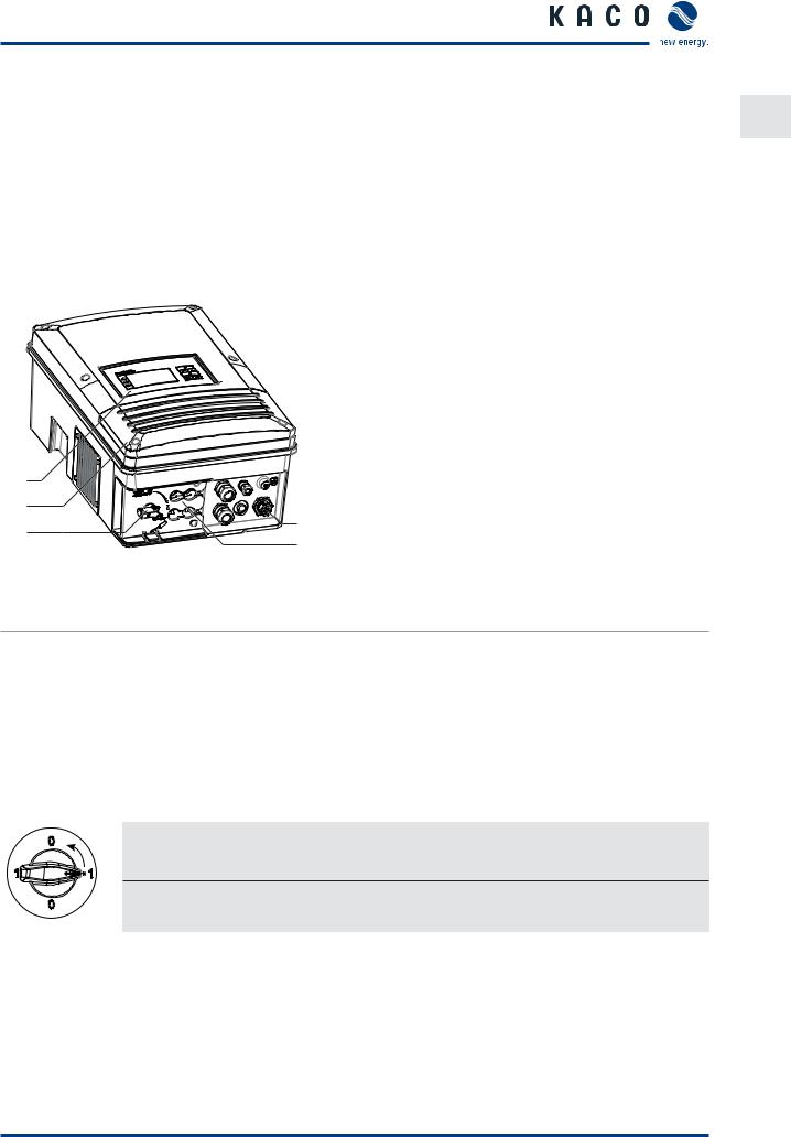
3.2Diagram
1 |
|
|
2 |
|
|
3 |
5 |
|
4 |
||
|
||
Figure 1: Inverter diagram |
|
Key
1 |
Control panel |
4 |
DC connection (DC connector) |
2 |
Cover for the connection area |
5 |
AC connection (5-pole connecting plug) |
3 |
DC isolator switch |
|
|
|
|
|
|
3.2.1Mechanical components
DC isolator switch
The DC isolator switch is located on the underside of the inverter. The DC isolator switch is used to disconnect the inverter from the PV generator in order to carry out service.
Disconnecting the inverter from the PV generator
Switch the DC isolator switches from 1 (ON) to 0 (OFF).
Connecting the inverter to the PV generator
Switch the DC isolator switches from 0 (OFF) to 1 (ON).
3.2.2Electrical functions
Fault signal relay/priwatt
A potential-free relay contact is integrated in the inverter. Use this contact for one of the following functions:
Fault signal relay
The potential-free relay contact closes as soon as there is a fault during operation. You use this function, for example, to signal a fault visually or acoustically.
Operating Manual KACO blueplanet 5.0TL3 - 9.0TL3 |
Page 7 |

Description
Priwatt
EN
The energy that is provided by the PV system can be put to use directly by the appliances that are connected in your home. In “priwatt” mode, the potential-free contact takes care of this function.
The potential-free contact switches larger consumers (e.g. air conditioning units) on and off. This requires an external power supply and an external load relay. Both can be obtained as part of the priwatt-switch from your specialist retailer.
When the function is active, either the remaining runtime (in hours and minutes) or the shutdown threshold (in kW) is displayed on the start screen depending on the operating mode selected. The “priwatt” function is not active in the unit’s delivery state. The option can be configured in the Settings menu.
3.2.3Interfaces
You configure the interfaces and the web server in the Settings menu.
The inverter has the following interfaces for communication and remote monitoring:
Ethernet interface
Monitoring can occur directly on the unit using the integrated Ethernet interface. A local web server is installed in the unit for this purpose.
For the monitoring of a system consisting of multiple inverters, we recommend the utilization of the Powador web portal on our homepage.
RS485 interface
In addition to the monitoring via the Ethernet interface, the monitoring can be executed via the RS485 interface. KACO new energy GmbH offers monitoring devices for the monitoring of your PV systems via the RS485 interface
Only the RS485 interface continues to transmit data if the inverter in an inverter group fails.
USB interface
The USB connection of the inverter is a type A socket. It is located on the connection circuit board behind the cover for the connection area. The USB connection is specified to draw 100 mA of power. Use the USB interface for reading out stored operating data and loading software updates using a FAT32-formatted USB stick.
"Inverter Off" input
If Powador protect is installed as a central grid and system protection, the fail-safe disconnection of suitable Powador or blueplanet inverters from the public grid can be initiated by a digital signal instead of tie circuit-breakers. This requires the inverters in the photovoltaic system to be connected to the Powador protect. For information on the installation and use see this manual, the Powador protect manual and the instructions for use of the Powador protect on the KACO new energy website.
S0 interface (optional)
The S0 interface transmits pulses between a pulsing counter and a tariff metering unit. It is a galvanically isolated transistor output. It is designed according to DIN EN 62053-31:1999-04 (pulse output devices for electromechanical and electronic meters).
The S0 interface pulse rate can be chosen in three unit intervals (500, 1,000 and 2,000 pulses/kWh).
The optional interface module is available from the service department of KACO new energy.
Page 8 |
Operating Manual KACO blueplanet 5.0TL3 - 9.0TL3 |
Description
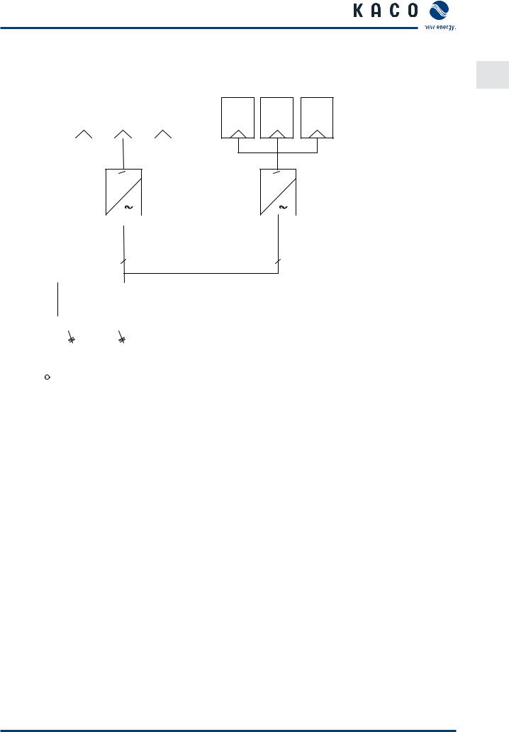
3.2.4Inverter as part of a PV system
|
PV generator |
|
|
PV generator |
|||||||||||
|
|
|
|
|
|
|
|
|
|
|
|
|
|
|
|
|
|
|
|
|
|
|
|
|
|
|
|
|
|
|
|
|
|
|
|
|
|
|
|
|
|
|
|
|
|
|
|
|
|
|
|
|
|
Inverter with |
|
|
|
|
|
Inverter with |
|
|
|
|
|
|
|
||||||||
|
|
|
|
|
|
DC isolator switch |
|
|
DC isolator switch |
||||
|
|
|
|
|
|
|
|
|
|
|
|||
|
|
|
|
|
Line protection |
|
Line protec- |
||||||
|
|
|
|||||||||||
|
|
|
|
|
|
|
|
|
|
|
tion |
||
|
|
|
|
|
|
|
|
|
|
|
|
|
|
Load
|
|
|
|
|
|
|
|
|
|
|
|
|
|
|
|
|
|
|
|
|
|
|
|
|
|
|
|
|
|
|
|
|
|
Reference counter |
|
|
KWh |
Feed-in meter |
||||||||||||
|
|
KWh |
|
|
|
|||||||||||
|
|
|
|
|
|
|
|
|
|
|
|
|
|
|
|
|
Main switch |
|
|
|
|
|
|
|
|
|
|
|
|
Selective main switch |
|||
|
|
|
|
|
|
|
|
|
|
|
|
|||||
|
|
|
|
|
|
|
|
|
|
|
|
|
|
|
|
|
|
|
|
|
|
|
|
|
|
|
|
|
|
|
|
|
|
|
|
|
|
|
|
|
|
|
|
|
|
|
|
|
|
|
Grid connection point
Figure 2: Circuit diagram of a system with two inverters
Key |
Definition / Information about the connection |
PV generator |
The PV generator, i.e. the PV modules, converts the radiant energy of |
|
sunlight into electrical energy. |
|
|
Inverter with: |
|
- DC connection |
The PV generator is connected directly to the inverter's DC connec- |
|
tion. The DC connection can be used to |
|
connect two strings. |
|
|
- DC isolator switch |
Use the DC isolator switch to disconnect the inverter from all power |
|
sources on the PV generator side. |
Circuit breaker |
A circuit breaker is an overcurrent protection device. |
Feed-in meter |
The feed-in meter is specified and installed by the power supply |
|
company. Some power supply companies also allow the installation |
|
of your own calibrated meters. |
|
|
Selective main switch |
If you have questions about the selective main switch, contact your |
|
power supply company. |
EN
Operating Manual KACO blueplanet 5.0TL3 - 9.0TL3 |
Page 9 |

Technical Data
EN |
4 |
Technical Data |
|
|
|
|
|
|
|
|
|
|
|
|
|
|
4.1 |
Electrical Data |
|
|
|
|
|
|
|
|
|
|
|||
|
|
Product name: KACO blueplanet |
5.0 TL3 |
6.5 TL3 |
7.5 TL3 |
9.0 TL3 |
|
|
|
|
|
|
|
|
|
|
|
Input levels |
|
|
|
|
|
|
|
|
|
|
|
|
|
|
|
MPP@Pnom range from [V] to [V] |
240 ... 800 |
310 ... 800 |
350 ... 800 |
420 ... 800 |
|
|
|
|
|
|
|
||
|
|
Operating range from [V] to [V] |
|
200 ... 950 |
|
||
|
|
|
|
|
|
|
|
|
|
Starting voltage [V]* |
|
|
250 |
|
|
|
|
|
|
|
|
||
|
|
No-load voltage (UOC max ) [V] |
|
1 000 (start to 950) |
|
||
|
|
|
|
|
|
|
|
|
|
Max. input current [A] |
|
|
2 x 11 |
|
|
|
|
|
|
|
|
|
|
|
|
Max. power per tracker [W] |
5 200 |
6 700 |
7 700 |
8 800 |
|
|
|
|
|
|
|
|
|
|
|
Number of strings |
|
|
2 |
|
|
|
|
|
|
|
|
|
|
|
|
Number of MPP controls |
|
|
2 |
|
|
|
|
|
|
|
|
||
|
|
max. short-circuit current (ISC max ) [A] |
|
16 (per tracker) / 32 (for parallel switching) |
|
||
|
|
|
|
|
|
|
|
|
|
Overvoltage safety class |
|
|
III |
|
|
|
|
|
|
|
|
||
|
|
* The DC starting voltage can be in the menu if needed. / |
|
|
|
||
|
|
|
|
|
|
|
|
|
|
Output levels |
|
|
|
|
|
|
|
|
|
|
|
|
|
|
|
Rated power [VA] |
5 000 |
6 500 |
7 500 |
9 000 |
|
|
|
|
|
|
|
||
|
|
Grid voltage [V] |
|
400/230 (3/N/PE) |
|
||
|
|
|
|
|
|
|
|
|
|
Rated current [A] |
3 x 7,25 |
3 x 9,5 |
3 x 10,9 |
3 x 13,0 |
|
|
|
|
|
|
|
|
|
|
|
Max. rated current [A] |
3 x 7,62 |
3 x 9,98 |
3 x 11,45 |
3 x 13,76 |
|
|
|
|
|
|
|
|
|
|
|
Rated frequency [Hz] |
|
|
50/60 |
|
|
|
|
|
|
|
|
||
|
|
Make current [A] and ON duration [ms] |
|
2,53 / 0,5 |
|
||
|
|
|
|
|
|
|
|
|
|
cos phi |
|
|
0,30 inductive ...0,30 capacitive |
|
|
|
|
|
|
|
|
|
|
|
|
Number of feed-in phases |
|
|
3 |
|
|
|
|
|
|
|
|
|
|
|
|
THD [%] |
|
|
|
3,85 |
|
|
|
|
|
|
|
|
|
|
|
Overvoltage safety class |
|
|
III |
|
|
|
|
|
|
|
|
|
|
|
|
General electrical data |
|
|
|
|
|
|
|
Efficiency [%] |
98,3 |
98,3 |
98,3 |
98,3 |
|
|
|
|
|
|
|
|
|
|
|
European efficiency [%] |
97,4 |
97,6 |
97,7 |
97,9 |
|
|
|
|
|
|
|
|
|
|
|
Internal consumption: night [W] |
|
|
2 |
|
|
|
|
|
|
|
|
|
|
|
|
Feed-in starts at [W] |
|
|
20 |
|
|
|
|
|
|
|
|
||
|
|
Circuit design |
|
Transformerless |
|
||
|
|
|
|
|
|
||
|
|
Grid monitoring |
|
Country-specific |
|
||
|
|
|
|
|
|
|
|
|
|
Ground fault monitoring |
|
|
Yes |
|
|
|
|
|
|
|
|
|
|
|
|
Table 1: |
Electrical Data |
|
|
|
|
Page 10 |
Operating Manual KACO blueplanet 5.0TL3 - 9.0TL3 |
Technical Data
4.2 |
Mechanical data |
|
|
|
EN |
|
|
|
|
|
|
Product name: KACO blueplanet |
5.0-9.0 TL3 |
|
|||
|
|||||
|
|
|
|
||
Display |
|
Graphical LCD, 3 LEDs |
|||
|
|
|
|
|
|
Controls |
|
4-way button, 2 buttons |
|||
|
|
|
|
|
|
Interfaces |
|
2x Ethernet, USB, RS485 |
|||
|
|
optional via additional module: S0, 4-DI, 4-D0 |
|||
|
|
|
|
||
Fault signal relay |
Potential-free NO contact, 230 V/1 A |
||||
|
|
|
|
||
AC connections |
5-pole connection plug |
||||
|
|
|
|
||
DC connections |
4 (2 x 2) SUNCLIX connector |
||||
|
|
|
|
||
Ethernet connection: Cable connection |
Cable connection via M25 cable fitting |
||||
|
|
|
|
||
Ambient temperature range [°C] |
-25 ... +60, derating from +40 |
||||
|
|
|
|
|
|
Humidity range (non-condensing) [%] |
100 |
|
|
|
|
|
|
|
|
|
|
Maximum installation elevation [m above sea level] |
3000 |
|
|
|
|
|
|
|
|
||
Temperature monitoring |
Yes |
||||
|
|
|
|
||
Cooling (free convection (K)/fan (L)) |
L |
||||
|
|
|
|
||
Protection rating according to EN 60529 |
IP65 |
||||
|
|
|
|
|
|
Degree of contamination |
2 |
|
|
|
|
|
|
|
|
||
Noise emission [dB(A)] |
< 45/noiseless without fan operation |
||||
|
|
|
|
||
DC isolator switch |
Built-in |
||||
|
|
|
|
|
|
Housing |
|
Plastic (ASA/PC), aluminium |
|||
|
|
|
|
||
H x W x D [mm] |
ca. 560 x 367 x 224 |
||||
|
|
|
|
|
|
Total weight [kg] |
30 |
|
|
|
|
|
|
|
|
|
|
Table 2: |
Mechanical data |
|
|
|
|
Operating Manual KACO blueplanet 5.0TL3 - 9.0TL3 |
Page 11 |

Transportation and Delivery
EN |
5 |
Transportation and Delivery |
|
|
|
|
5.1 |
Delivery |
|
Every inverter leaves our factory in proper electrical and mechanical condition. Special packaging ensures that the units are transported safely. The shipping company is responsible for any transport damage that occurs.
Scope of delivery
•1 inverter
•1 wall bracket
•1 installation kit
•1 documentation set
Checking your delivery
1.Inspect your inverter thoroughly.
2.Immediately notify the shipping company in case of the following:
–Damage to the packaging that indicates that the inverter may have been damaged
–Obvious damage to the inverter
3.Send a damage report to the shipping company immediately.
The damage report must be received by the shipping company in writing within six days following receipt of the inverter. We will be glad to help you if necessary.
5.2Transportation
WARNING
Impact hazard, risk of breakage to the inverter
›Pack the inverter securely for transport.
›Carefully transport the inverter using the carrying handles of the boxes.
›Do not subject the inverter to shocks.
For safe transportation of the inverter, use the holding openings in the carton.
Figure 3: Transportation of the inverter
Page 12 |
Operating Manual KACO blueplanet 5.0TL3 - 9.0TL3 |
Mounting
6 |
Mounting |
|
|||
EN |
|||||
|
|
|
|
||
|
|
|
|
|
|
DANGER
Risk of fatal injury from fire or explosions
Fire caused by flammable or explosive materials in the vicinity of the inverter can lead to serious injuries.
›Do not mount the inverter in an area at risk of explosion or in the vicinity of highly flammable materials.
CAUTION
Risk of burns from hot housing components.
Coming into contact with the housing can cause burns.
› Mount the inverter so that it cannot be touched unintentionally.
Installation space
•As dry as possible, climate-controlled, with the waste heat dissipated away from the inverter,
•Unobstructed air circulation,
•When installing the unit in a control cabinet, provide forced ventilation so that the heat is sufficiently dissipated,
•Access to the inverter must also be possible without additional tools,
•For outdoor installation, fit the inverters in such a way to ensure that they are protected against direct sunlight, moisture - and dust penetration,
•For easy operation, ensure during installation that the display is slightly below eye level.
Wall
•With sufficient load-bearing capacity
•Accessible for installation and maintenance
•Made from heat-resistant material (up to 90 °C),
•Flame resistant
•Minimum clearances to be observed during assembly: see Figure 8 on page 16.
NOTE
Access by maintenance personnel for service
Any additional costs arising from unfavourable structural or mounting conditions shall be billed to the customer.
CAUTION
Property damage due to gases that have an abrasive effect on surfaces when they come into contact with
ambient humidity caused by weather conditions.
The inverter housing can be severely damaged by gases (ammonia, sulphur, etc.) if it comes into contact with ambient humidity caused by weather conditions.
If the inverter is exposed to gases, it must be mounted so that it can be seen at all times.
›Perform regular visual inspections.
›Immediately remove any moisture from the housing.
›Take care to ensure sufficient ventilation of the inverter.
›Immediately remove dirt, especially on vents.
›Failure to observe these warnings may lead to inverter damage which is not covered by the KACO new energy GmbH manufacturer warranty.
Operating Manual KACO blueplanet 5.0TL3 - 9.0TL3 |
Page 13 |

Mounting
EN
NOTE
Power reduction due to heat accumulation.
If the recommended minimum clearances are not observed, the inverter may go into power regulation mode due to insufficient ventilation and the resulting heat build-up.
›Maintain minimum clearances.
›Provide for sufficient heat dissipation.
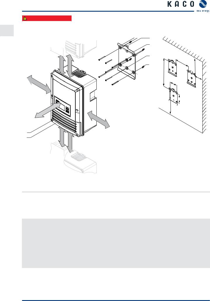
<20° |
Figure 4: Instructions for wall mounting |
Figure 5: Inverter for outdoor installation |
|
|
|
|
|
|
|
|
|
|
CAUTION
Use suitable mounting parts.
›Use only the supplied mounting parts.
›Mount the inverter upright on a vertical wall only.
›For a free-standing mounting an incline of 20° is allowed.
Page 14 |
Operating Manual KACO blueplanet 5.0TL3 - 9.0TL3 |

Mounting
6.1 Unpacking |
EN |
|
CAUTION
The inverter is very heavy – risk of injury!
›Observe the weight of the inverter during transport.
›Select suitable mounting location and mounting base.
›Use mounting material corresponding to or included with the base for mounting the inverter.
›Transport and install the inverter with at least 2 persons.
|
|
1 |
|
|
2 |
|
|
|
3 |
|
|
Figure 6: Unpacking the inverter |
|
Figure 7: Lifting the inverter |
|
Key |
|
|
|
1 |
Carton |
3 |
Inverter |
2Protective packaging
Unpacking the inverter
1.Open carton at the front.
2.Remove installation material and documentation.
3.Carefully slide the inverter with its protective packaging out of the carton.
4.Place the protective packaging back into the carton during mounting.
5.Lift the inverters to the intended positions (see Figure 7).
»Continue mounting the inverter.
Operating Manual KACO blueplanet 5.0TL3 - 9.0TL3 |
Page 15 |
|
Mounting |
|
Authorised electrician |
EN |
6.2 Mounting |
|
500 mm |
700 mm |
 150mm
150mm
|
250mm |
150mm |
|
|
|
||
2 |
500mm |
mm700 |
|
1 |
|||
|
|
3 |
4 |
5 |
510
6
582
1220 


 216
216
160


 180 920

Figure 8: Minimum clearances/mounting plate
Key
1 |
Cover for connection area |
4 |
Mounting plate |
2 |
Screws for mounting (2x Torx) |
5 |
Screws for mounting |
|
|
|
|
3 |
Suspension bracket |
6 |
Fixings for mounting |
Mounting the inverter
1.Mark the positions of the drill holes using the cut-outs in the mounting plate.
NOTE: The minimum clearances between two inverters, or the inverter and the ceiling/floor have already been taken into account in the diagram.
2.Fix mounting plate to the wall with the supplied mounting fixtures. Make sure that the mounting plate is oriented correctly.
3.Hang the inverter on the mounting plate using the suspension brackets on the back of the housing.
4.Fix the inverter with the enclosed screws to the Suspension bracket of the mounting plate.
»The mounting of the inverter is complete. Continue with the installation.
Page 16 |
Operating Manual KACO blueplanet 5.0TL3 - 9.0TL3 |
Installation
|
Authorised electrician |
|
7 |
Installation |
EN |
|
|
DANGER
Lethal voltages are still present in the terminals and cables of the inverter even after the inverter has been switched off and disconnected.
Severe injuries or death result if the cables and terminals in the inverter are touched.
The inverter must only be opened and installed by an accredited electrician, who has been approved by the public power supplier (country-specific).
The inverter must be mounted in a fixed position before being connected electrically.
›Observe all safety regulations and current technical connection specifications of the responsible power supply company.
›Disconnect the AC and DC sides.
›Secure both sides against being inadvertently switched back on.
›Ensure that the AC and DC sides are completely isolated and voltage free.
›Connect the inverter only after the aforementioned steps have been taken.
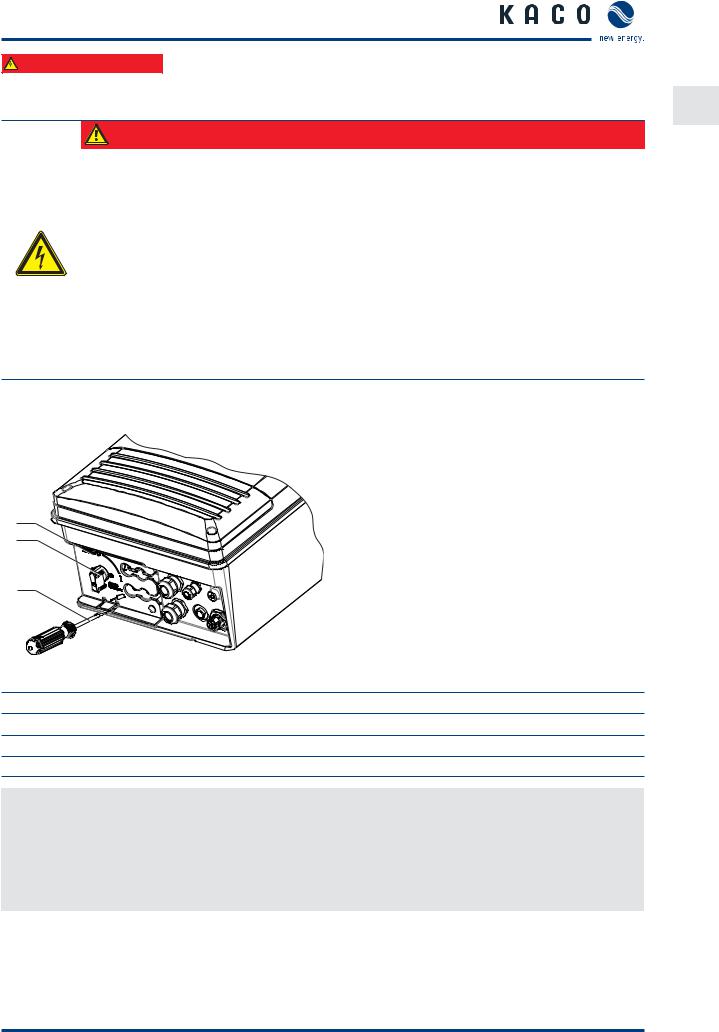
7.1Opening the connection area
3
2
1
Figure 9: Uncover the DC connection
Key
1Screwdriver
2 Cover to safeguard the DC connections
3DC isolator switch
Opening the connection area
You have mounted the inverter on the wall.
1.Switch the DC isolator switches to 0 to remove the cover.
2.Carefully unlatch cover at the marked position using a screwdriver.
3.Remove cover and store for connection.
»Make the electrical connection.
Operating Manual KACO blueplanet 5.0TL3 - 9.0TL3 |
Page 17 |
 Loading...