

Page 1
SERVICE MANUAL
AUDIO/VIDEO CONTROL RECEIVER
RX-9010VBK
Area Suffix
J U.S.A.
RX-9010VBK
STANDBY
ON
SUB ROOMMAIN ROOM
MAIN ROOM
TV/CATV/DBS
VCR1
SUB ROOM
ON/OFF ON/OFF POWER POWER
DVD
DVD MULTI CD
PHONO
CDR
TAPE/MD
VCR 1 VCR 2
USB AUDIO
FM/AMVIDEOTV/DBS
ANALOG/DIGITAL
EFFECT
L—BALANCE—R
INPUT
123
CENTER SUBWFR
ROOM SIZE
SOUND
456
LIVENESS
REAR·L
REAR·R
LEVEL+
789
LEVEL–
DIGITAL EQ
10
RETURN
TEST
SURROUND
ON/OFF MODE
LINE DIRECT
SLEEP
/REW
DOWN UP
REC
CHANNEL
TV VOL
MENU
DVD
MENU
RM-SRX9010J
A/V CONTROL RECEIVER
FM MODE
DSP BASS BOOST
MIDNIGHT MODE
CONTROL
PLAY
TUNING
STOP PAUSE
TV/VIDEO
MUTING
SET
REMOTE CONTROL
CENTER TONE
+
100
+
100
DIMMER
TV
CATV/
DBS
VOLUME
FF/
TEXT
DISPLAY
EXIT
SPEAKERS ON/OFF
SUBWOOFER OUT ON/OFF
PHONES
MAIN ROOM
SUB ROOM
STANDBY
POWER
1
2
FM/AM TUNING FM/AM PRESET FM MODE
DIGITAL
DIGITAL
SURROUND
SURROUND ON/OFF
USB AUDIO
S-VIDEO VIDEO
MEMORY
INPUT
ANALOG/DIGITAL
INPUT ATT
VIDEO
MIDNIGHT MODEDSP MODE
L—AUDIO—R
AUDIO/VIDEO CONTROL RECEIVER
RX-9010V
SOURCE NAME
TV SOUND/DBSVIDEOVCR 2VCR 1DVDDVD MULTI
SOURCE NAME
FM / AMUSB AUDIOTAPE / MDCDRCDPHONO
MAIN ROOM ON/OFF SUB ROOM ON/OFF SUB ROOM CONTROL DIMMER
LEVEL
DIGITAL
ADJUST
EQ
EFFECT SETTING
CONTROL
DOWN UP
MASTER VOLUME
LINE DIRECT
BASS BOOST
Contents
Safety precautions --------------------------------------------------------1-2
Importance administering point on the safety --------------------- 1-3
Disassembly method -----------------------------------------------------1-4
Adjustment method -------------------------------------------------------1-10
Self-diagnose function ----------------------------------------------------1-11
Description of major ICs -------------------------------------------------1-13 30
DIGITAL
COPYRIGHT 2001 VICTOR COMPANY OF JAPAN, LTD.
No.20940
Apr. 2001
Page 2
RX-9010VBK
1. This design of this product contains special hardware and many circuits and components specially for safety
purposes. For continued protection, no changes should be made to the original design unless authorized in
writing by the manufacturer. Replacement parts must be identical to those used in the original circuits. Services
should be performed by qualified personnel only.
2. Alterations of the design or circuitr y of the product should not be made. Any design alterations of the product
should not be made. Any design alterations or additions will void the manufacturer`s warranty and will fur ther
relieve the manufacture of responsibility for personal injury or property damage resulting therefrom.
3. Many electrical and mechanical parts in the products have special safety-related characteristics. These
characteristics are often not evident from visual inspection nor can the protection afforded by them necessarily
be obtained by using replacement components rated for higher voltage, wattage, etc. Replacement par ts which
have these special safety characteristics are identified in the Parts List of Service Manual. Electrical
components having such features are identified by shading on the schematics and by ( ) on the Parts List in
the Service Manual. The use of a substitute replacement which does not have the same safety characteristics
as the recommended replacement parts shown in the Parts List of Service Manual may create shock, fire, or
other hazards.
4. The leads in the products are routed and dressed with ties, clamps, tubings, barriers and the like to be
separated from live parts, high temperature parts, moving parts and/or sharp edges for the prevention of
electric shock and fire hazard. When service is required, the original lead routing and dress should be
observed, and it should be confirmed that they have been returned to normal, after re-assembling.
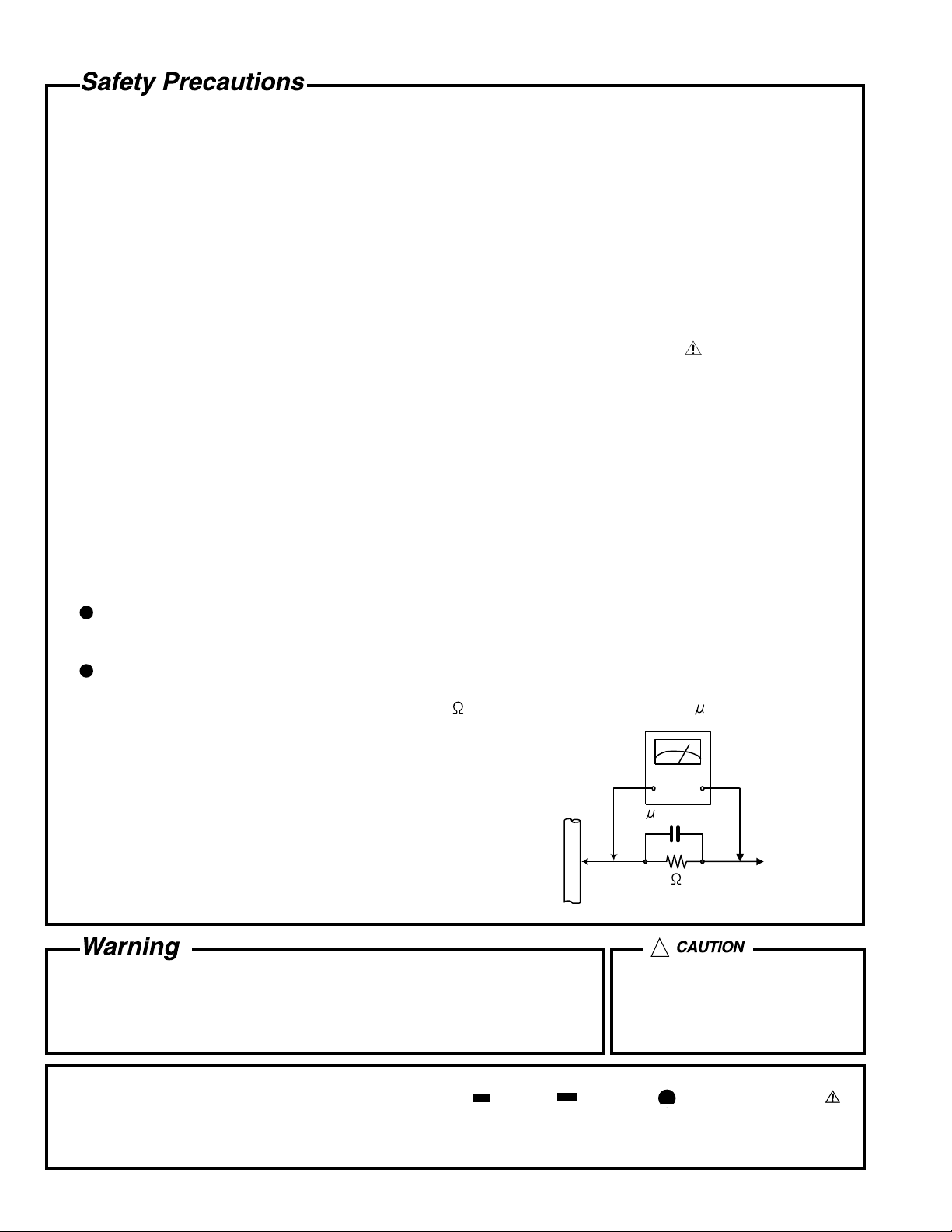
5. Leakage currnet check (Electrical shock hazard testing)
After re-assembling the product, always perform an isolation check on the exposed metal parts of the product
(antenna terminals, knobs, metal cabinet, screw heads, headphone jack, control shafts, etc.) to be sure the
product is safe to operate without danger of electrical shock.
Do not use a line isolation transformer during this check.
Plug the AC line cord directly into the AC outlet. Using a "Leakage Current Tester", measure the leakage
current from each exposed metal parts of the cabinet, particularly any exposed metal part having a return
path to the chassis, to a known good earth ground. Any leakage current must not exceed 0.5mA AC (r.m.s.).
Alternate check method
Plug the AC line cord directly into the AC outlet. Use an AC voltmeter having, 1,000 ohms per volt or more
sensitivity in the following manner. Connect a 1,500 10W resistor paralleled by a 0.15 F AC-type capacitor
between an exposed metal part and a known good earth ground.
Measure the AC voltage across the resistor with the AC
voltmeter.
Move the resistor connection to eachexposed metal part,
particularly any exposed metal part having a return path to
the chassis, and meausre the AC voltage across the resistor.
Now, reverse the plug in the AC outlet and repeat each
measurement. voltage measured Any must not exceed 0.75 V
AC (r.m.s.). This corresponds to 0.5 mA AC (r.m.s.).
0.15 F AC TYPE
1500 10W
Good earth ground
AC VOLTMETER
(Having 1000
ohms/volts,
or more sensitivity)
Place this
probe on
each exposed
metal part.
!
1. This equipment has been designed and manufactured to meet international safety standards.
2. It is the legal responsibility of the repairer to ensure that these safety standards are maintained.
3. Repairs m ust be made in accordance with the relevant safety standards.
4. It is essential that safety critical components are replaced by approved parts.
5. If mains voltage selector is provided, check setting for local voltage.
Burrs formed during molding may
be left over on some parts of the
chassis. Therefore, pay attention to
such burrs in the case of
preforming repair of this system.
In regard with component parts appearing on the silk-screen pr inted side (parts side) of the PWB diagrams, the
parts that are printed over with black such as the resistor ( ), diode ( ) and ICP ( ) or identified by the " "
mark nearby are critical for safety.
When replacing them, be sure to use the parts of the same type and rating as specified by the manufacturer.
(Except the JC version)
1-2
Page 3
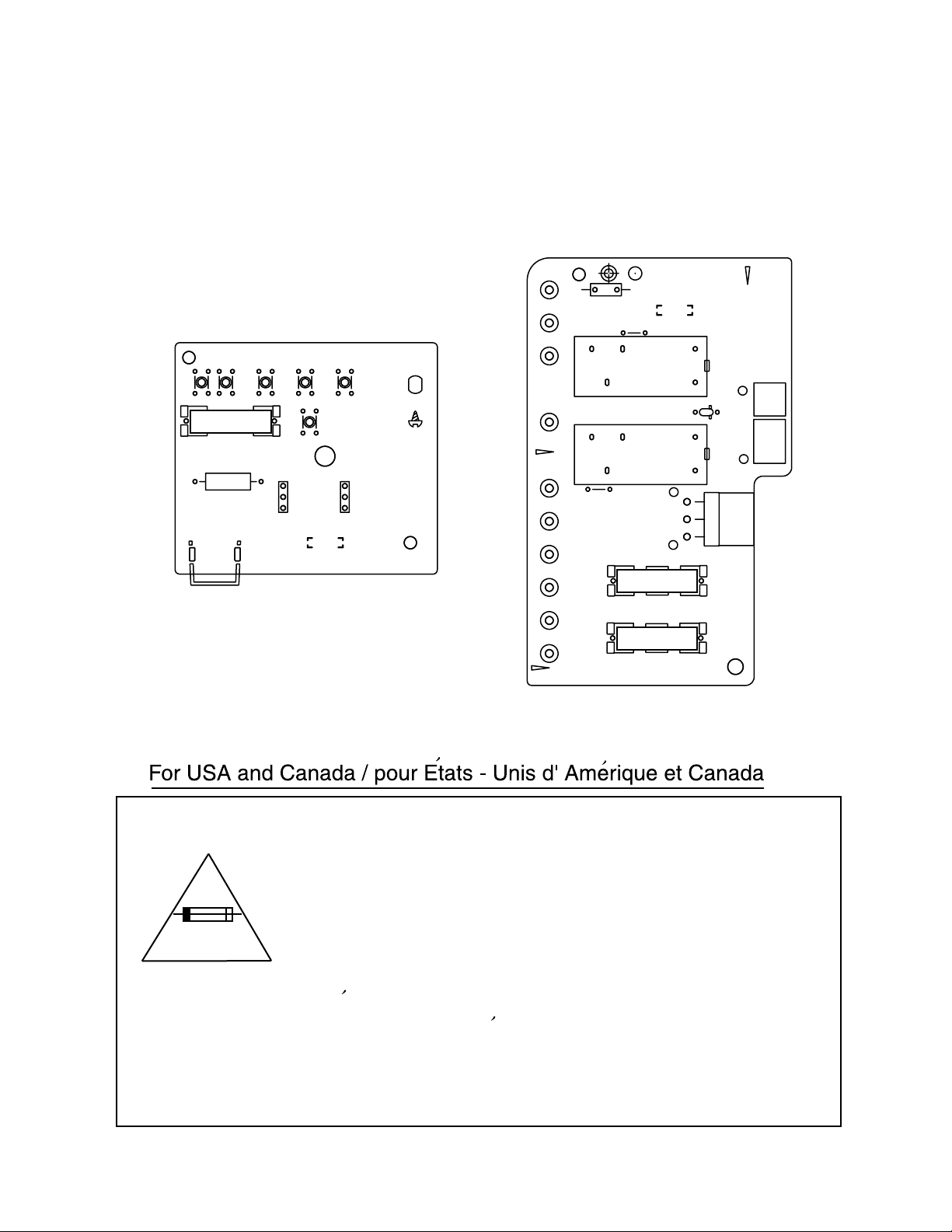
Importance administering point on the safety
131
PW17
PW20
B3141
B3143
B3142
FC1
6.3A-125V
R61
132
PW19
PW26
PW18
B3148
B3151
B3150
B3152
PW30
TA1
B3147
B3145
B3146
B3144
FC2
B3149
TA2
R1
113
112
111
123
B3191
B3192
LVA10222-A6
RY63
RY62
RX-9010VBK
CN55
D67
CN56
CN811
EP1
122
LVA10222-A3
FC62
FC64
2A-125V
2A-125V
FC61
FC63
121
134
133
Caution: For continued protection against risk of
fire, replace only with same type 6.3A/125V for
F201, 2A/125V for F202 and F203. This symbol
specifies type of fast operating fuse.
Precaution: Pour eviter risques de feux, remplacez
le fusible de surete de F201 comme le meme type
que 6.3A/125V, et 2A/125V pour F202 et F203.
Ce sont des fusibles suretes qui functionnes rapide.
^
1-3
Page 4
RX-9010VBK
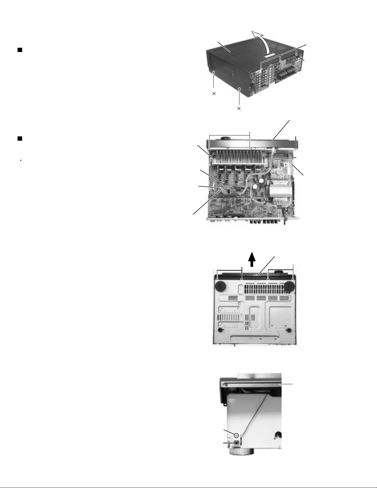
Disassembly method
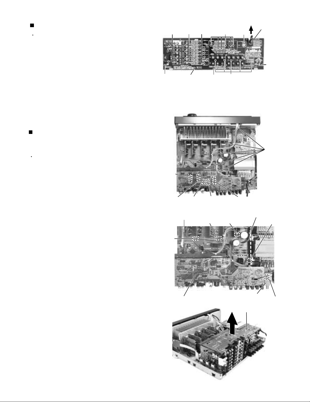
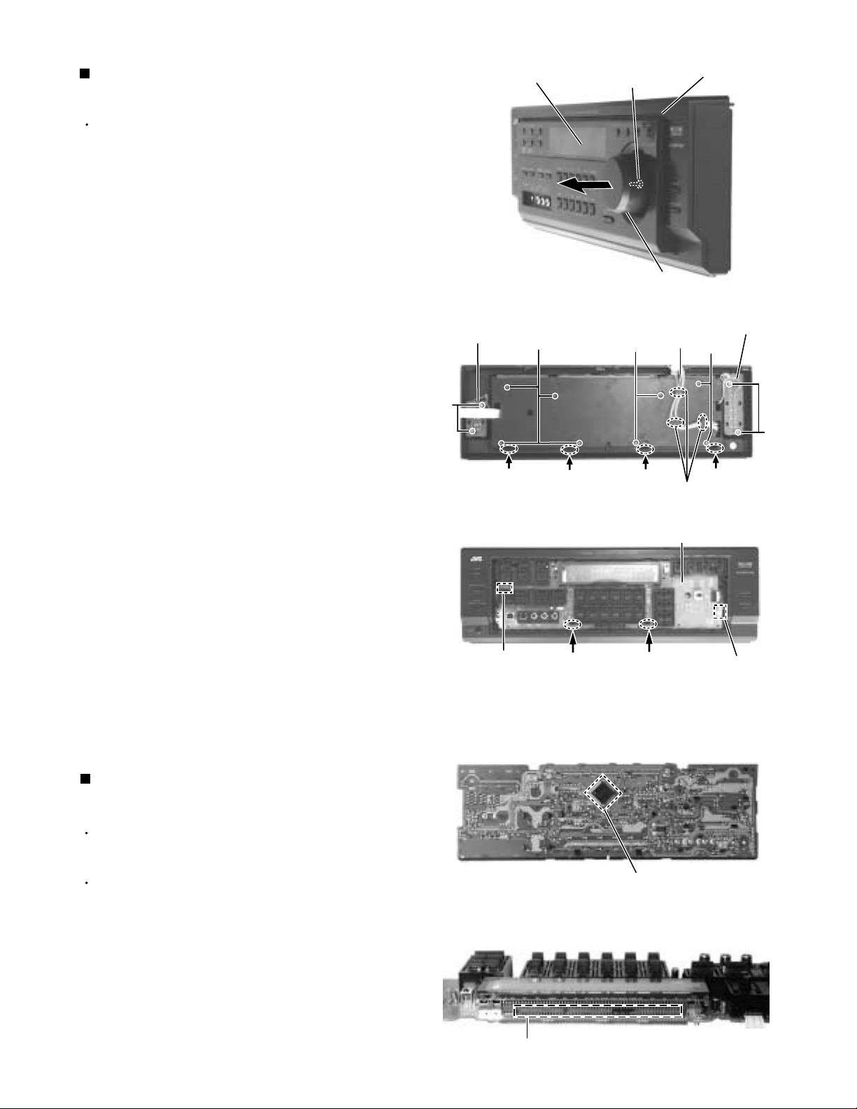
Removing the top cover (See Fig.1)
1.
Remove the four screws A attaching the top cover
on both sides of the body.
2.
Remove the three screws B on the back of the body.
3.
Remove the top cover from behind in the direction of
the arrow while pulling both sides outward.
Removing the front panel assembly
(See Fig.2 to 4)
Prior to performing the following procedure, remove
the top cover.
1.
Disconnect the card wire from connector CN400 on
the audio board and CN402 on the power supply
board in the front panel assembly.
2.
Cut off the tie band fixing the harness.
3.
Remove the three screws C attaching the front
panel assembly.
Top cover
Tie band
Main
board
CN400
Audio board
A
B
2
A
2
Fig.1
Front panel assembly
C
C
CN402
Power
supply
board
Fig.2
4.
Remove the four screws D attaching the front panel
assembly on the bottom of the body. Detach the front
panel assembly toward the front.
5.
Remove the screw a fixing a bonding ground.
D
Front panel assembly
D
Fig.3
Front panel
assembly
1-4
a
Headphone jack
Fig.4
Page 5
RX-9010VBK
Removing the rear panel (See Fig.5)
Prior to performing the following procedure, remove
the top cover.
1.
Remove the power cord stopper from the rear panel
by moving it in the direction of the arrow.
2.
Remove the thirty five screws E and a hexagon nut b
attaching the each boards to the rear panel on the
back of the body.
3.
Remove the three screws F attaching the rear panel
on the back of the body.
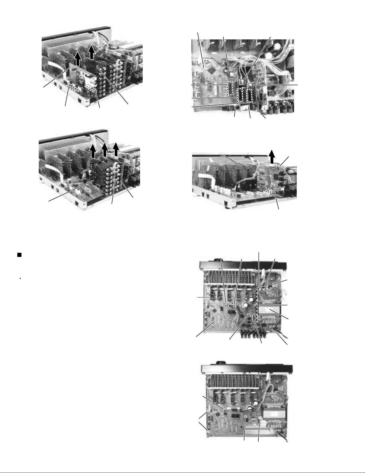
Removing each board connected to the
rear side of the audio board
(See Fig.6 to 12)
Prior to performing the following procedure, remove
the top cover and the rear panel.
E
Rear panel
EEEb
Cord stopper
F
FEF
Fig.5
Tie band
1.
Cut off the tie band fixing the harness.
2.
Disconnect the connect CN501, CN243, CN205,
CN381, CN361 on the DVD board.
3.
Disconnect the harness from connector CN721,
CN722 and CN723 on the main board.
4.
Disconnect the harness from connector CN1 on the
antenna unit and remove the antenna unit.
5.
Disconnect the harness from connector CN491 on
the relay board.
6.
Disconnect the tuner board and audio board from
connector CN101 and CN301 on the audio board.
7.
Pull out the video audio board, video board, S-video
board.
8.
Disconnect the DSP board from connector CN601 on
the audio board.
CN361
CN381 CN243
Main board
CN723
CN205
DVD board
Fig.6
CN721
Fig.7
CN722
CN501
Relay board
Antenna unit
DVD board
CN491
CN1
Fig.8
1-5
Page 6
RX-9010VBK
Tuner
board
CN101
CN301
Fig.9
Audio input
board
Audio board
CN303
CN201
CN241
CN416
Video audio
board
Video
board
Fig.10
CN206
CN244
S Video
board
DSP board
Video audio
board
Video
board
S Video
board
Fig.11 Fig.12
Removing the audio board
(See Fig.13 to 14)
Prior to performing the following procedure, remove
the top cover and the rear panel.
1.
Disconnect the harness from connector CN813 and
CN814 on the main board.
2.
Disconnect the card wire from connector CN931 and
CN932 on the audio board.
3.
Cut off the tie band fixing the harness.
4.
Disconnect the relay board from the audio board and
the power supply board. (CN71,CN81)
Main
board
Audio board
CN814
CN931/ 932
CN813
Fig.13
CN601
Relay board
CN71
CN81
power
supply
board
Tie band
Power
transformer
Power / Fuse
board
5.
Disconnect the card wire from connector CN831 on
the main board.
6.
Remove the three screws G attaching the audio
board assembly.
7.
Remove the screw H attaching the audio board
assembly.
1-6
CN831
G
G
Fig.14
H
Page 7
Removing the main board (See Fig.15)
Prior to performing the following procedure, remove
the top cover, the rear panel and audio board.
RX-9010VBK
I
J
I
1.
Cut off the tie band fixing the harness.
2.
Disconnect the harness from connector CN811 on
the power supply board respectively.
3.
Disconnect the harness from connector CN881 on
the main board.
NOTE:
In order to prevent the wire of CN881 from touching
to the wire of CN813,the wire of CN881 is secured
by tape. This is one of the preventive measures
for possible troubles of the remote controller.
When assembling the unit,secure the wire of CN881
with the original tape so as to prevent both wire from
touching each other.
4.
Remove the four screws I and the two screws J
attaching the main board.
J
I
Main
board
CN813
CN881
I
Fig.15
J
CN811
Tie band
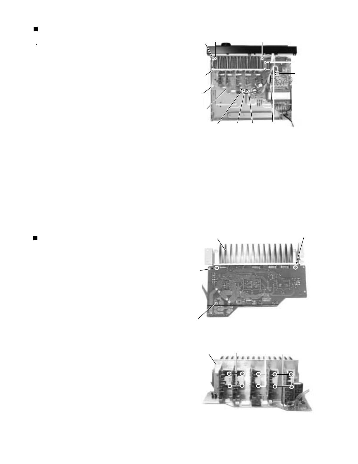
Removing the Amp board
(See Fig.16 to 17)
1.
Remove the two screws L attaching the rear side of
main board from the heat sink .
2.
Remove the ten screws K attaching each amp board
from the heat sink.
Heat sink
L
Main board
rear side
Heat sink
K
Fig.16
K
L
K
Fig.17
1-7
Page 8
RX-9010VBK
Removing the power transformer
(See Fig.18)
Prior to performing the following procedures, remove
the top cover.
1.
Unsolder the two harnesses connected to the power
transformer.
2.
Disconnect the harness from connector CN55 and
CN56 on the power transformer board.
3.
Remove the four screws M attaching the power
transformer.
Power
transformer
board
CN55 / 56
Power
supply
board
M
Power
transformer
Removing the power / fuse board
(See Fig.18)
Prior to performing the following procedure, remove
the top cover and the rear panel.
1.
Remove the screw N attaching the power / fuse
board.
2.
Unsolder the power cord and other harnesses
connected to the power / fuse board.
Removing the power supply board
(See Fig.19 to 20)
Prior to performing the following procedure, remove
the top cover and the front panel.
1.
Remove the one nut attaching the headphone jack of
the power supply board on the front side of the body.
2.
Disconnect the card wire from connector CN402 on
the power supply board.
Solder
Power
supply
board
Power cord
Fig.18
Fig.19
M
N
Solder
Power / fuse board
Headphone jack
Nut
3.
Remove the three screws O attaching the power
supply board and pull out the power supply board
from the front bracket backward.
4.
Unsolder the three harnesses connected to the
power supply board.
1-8
O
CN402
Hook
Power supply
board
Fig.20
Headphone jack
O
Tie band
O
Tie band
Solder
Page 9
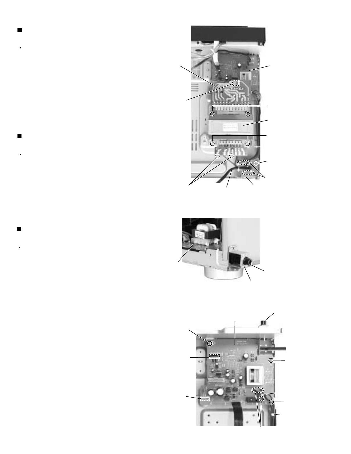
RX-9010VBK
Removing the system control board /
power switch board (See Fig.21 to 23)
Prior to performing the following procedure, remove
the top cover and the front panel assembly.
1.
Pull out the volume knob on the front side of the front
panel and remove the nut attaching the system
control board.
2.
Remove the two screws P attaching the power
switch board.
3.
Remove the two screws Q attaching the switch
board.
4.
Remove the cords from the three hooks a.
5.
Remove the eight screws R attaching the system
control board on the back of the front panel.
6.
On the back of the front panel, release the four joints
by pushing the joint tabs inward.
Remove the operation switch panel toward the front.
7.
Disconnect the harness from connector CN420 and
CN422 on the system control board.
8.
Release the two hooks b attaching the system
control board.
Operation switch panel
Switch
board
Q
Joint
R
Joint
Front panel assembly
Nut
Volume knob
Fig.21
Cords
R
Joint
Fig.22
System control board
Hook a
Power switch
board
R
P
Joint
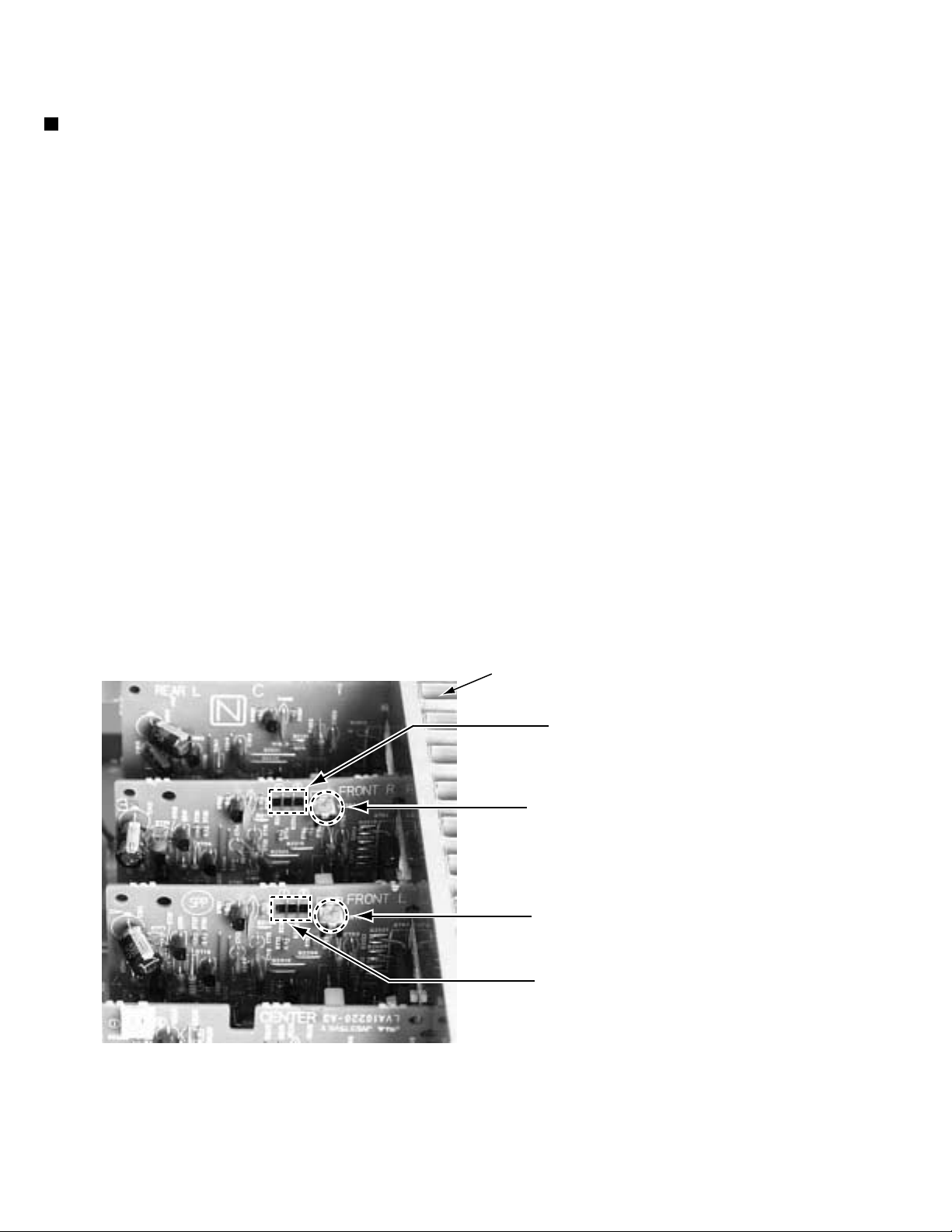
Matters that require attention during
replacement of IC400 (See Fig.24 to 25)
In case where there is a resistance array:
Both onetime IC and mask IC can be used
In case where there is no resistance array:
Only mask IC can be used
CN420
Resistance array
Hook b
System control board reverse side
Hook b
Fig.23
IC400
Fig.24
System control board top view
Fig.25
CN422
1-9
Page 10
RX-9010VBK
Adjustment method
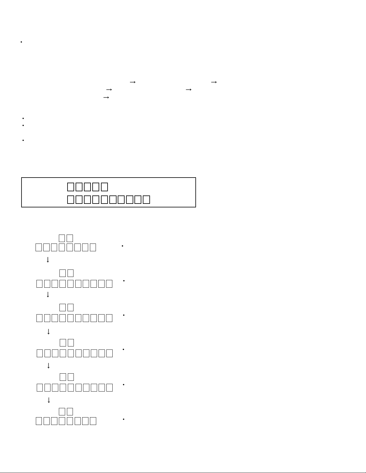
Power amplifier section
Adjustment of idling current
Measurement terminal B2204-B2205(Lch) , B2213-2214(Rch)
Adjustment volume VR787(Lch) , VR788(Rch)
Attention
This adjustment does not obtain a correct adjustment value immediately after the amplifier is
used (state that an internal temperature has risen).
Please adjust immediately after using the amplifier after turning off the power supply of the
amplifier and falling an internal temperature.
<Adjustment method>
1. Prior to turning the power ON, fully turn the adjusting resistor (VR787(Lch),VR788(Rch)) counterclockwise
direction and connect the DC voltmeter to the measuring terminal(B2204-B2205(Lch) , B2213-2214(Rch)).
2. Set the surround mode OFF.
3. Adjust the resistor so that the measured value becomes 2mV immediately after turning the power ON.
4. When the idling current has been stable (about 30 minutes after the power is turned ON),
confirm that the measured value falls within 1.0mV `10mV(2.3mV).
* It is not abnormal though the idling current might not become 0mA even if it is finished to turn variable
resistance (VR787,VR788) in the direction of counterclockwise.
Heat sink
B2213, B2214 (Rch)
VR788 (Rch)
VR787 (Lch)
1-10
B2204, B2205 (Lch)
Page 11
Self-diagnose function
1. Detection of abnormal power supply and voltage
When the power is turned ON, if an abnormality is detected during the signal input at the A/D port (IC901,
pin 2-5, 7) for one second continuously, the status will become STANDBY mode immediately.
When the power is turned ON again, detection of abnormal power supply and voltage will not be carried out
during the first 4 seconds.
Given below is a list of threshold values at the detection of abnormalities.
RX-9010VBK
Pin 2
Micro-computer+5V
Pin 3
Digital+5V
Pin 4
Analog+5V
Pin 5
+12V
Pin 7
Tuner+9V
At abnormal state
(Low voltage)
Analog value
0 - 2.2V
Analog value
0 - 2.2V
Analog value
0 - 2.2V
Analog value
0 - 2.2V
Analog value
0 - 2.2V
At abnormal state
Analog value
2.2 - 2.8V
Analog value
2.2 - 2.8V
Analog value
2.2 - 2.8V
Analog value
2.2 - 2.8V
Analog value
2.2 - 2.8V
At abnormal state
(High voltage)
Analog value
2.8 - 5.0V
Analog value
2.8 - 5.0V
Analog value
2.8 - 5.0V
Analog value
2.8 - 5.0V
Analog value
2.8 - 5.0V
2. Initial setting on ship
To gain the initial setting on ship, put the power plug in the socket while pressing DOWN key and UP key
together simultaneously, then turn the power ON.
3. Test mode
To enter the test mode, put the power plug in the socket while pressing EFFECT key and UP key together
simultaneously, then turn the power ON.
Workings of test mode:
All FLs are turned ON for 3 seconds. (the FLs, which are divided in two groups, are turned ON alternatively)
Faster volume UP/DOWN operation can be achieved with the remote controller.
When the power is turned OFF, the test mode will be released.
The FL display returns to normal after the three seconds. Then the STANDBY LED is turned ON (flashing
ON and OFF for each one second) to show the present status being a test mode.
1-11
Page 12
RX-9010VBK
4. Self-diagnose
To enter the self-diagnose mode, put the power plug in the socket while pressing SETTING key and UP key
together simultaneously, then turn the power ON. With the UP/DOWN key operation, DSP microcomputer,
ROM No.of system microcomputer as well as working status of DSP can be displayed for five seconds.
While the working status is being displayed, the followings items can be switched with the UP/DOWN key
operation.
VERSION of system microcomputer Local microcomputer CH0
Local microcomputer CH01 Local microcomputer CH2
Local microcomputer CH3 Local microcomputer CH4
When the power is turned OFF, the self-diagnose mode will be released.
During the self-diagnose mode, the STANDBY LED is turned ON .
(flashing ON for one second then OFF for three seconds)
FL transient display will be carried out as follows. When the transient display is not carried out,
normal display/workings are carried out.
FL Display
S 0 0 1 1
2 0 0 0 1 2 0 9 0 0
D 0 0
D 0 1
D 0 2
Upper 1 2 3 4 5 digits
Lower 1 2 3 4 5 6 7 8 9 10 digits
Information on VERSION of system microcomputer (IC901)
Example : VER1.1 2000/12/9
Display of communication information on DSP microcomputer (IC581)
Display of communication information on DIR AK4112A (IC551)
Display of communication information on DSP XCA56367 (IC501)
1-12
D 0 3
D 0 4 1 1
2 0 0 0 1 2 0 9 0 0
Display of communication information on CODEC AK4527 (IC571)
Information on VERSION of DSP microcomputer (IC581)
Example :VER1.1 2000/12/9
Page 13
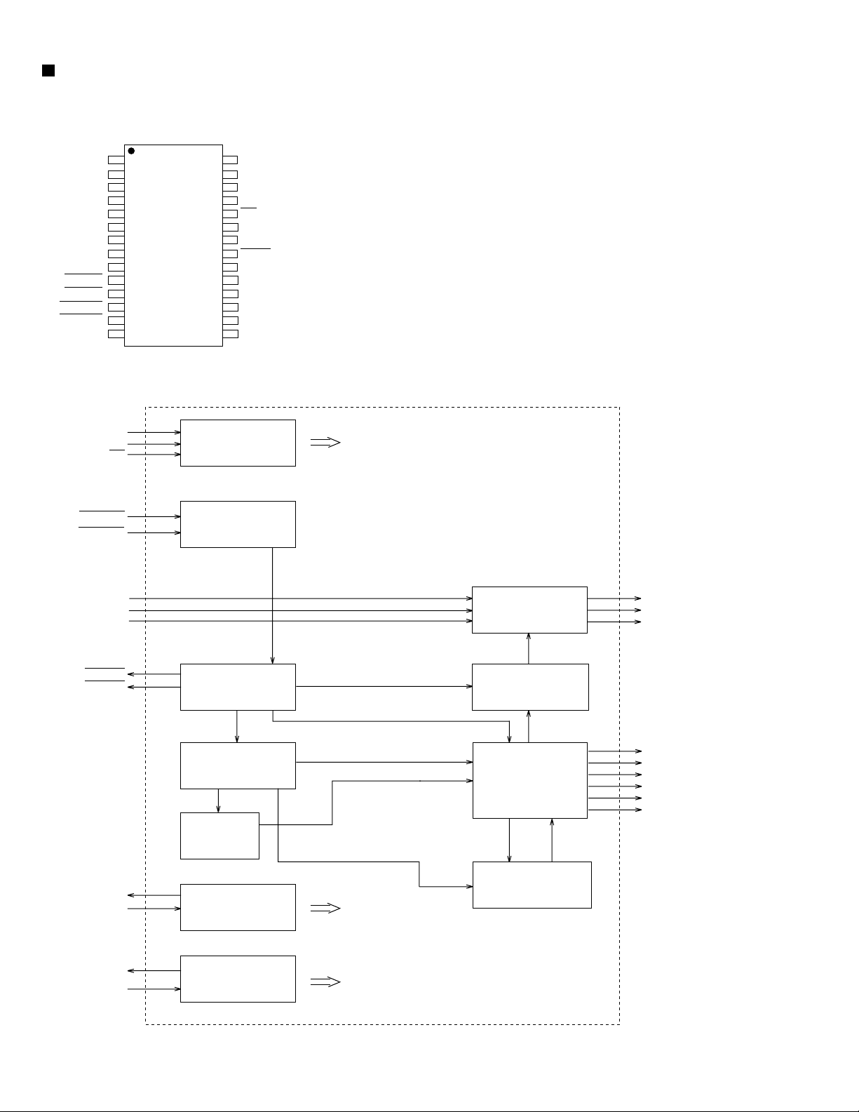
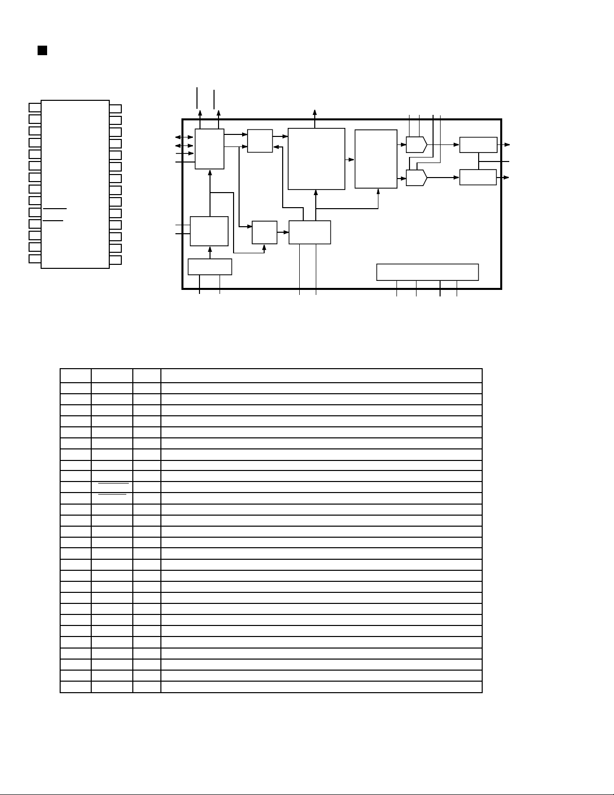
Description of major ICs
AK4527 (IC571) : A/D,D/A Converter
1.Pin layout
LOOP1
LOOP0/SDA/CDTI
DIF1/SCL/CCLK
DIF0/CSN
P/S
MCLK
DZF1
AVSS
AVDD
VREFH
VCOM
RX-9010VBK
SDOS
OCKS
MIS
BCLK
LRCK
SDTI1
SDTI2
SDTI3
SDTO
DAUX
DFS
2.Block diagram
LIN+
LIN-
4443424140393837363534
1
2
3
4
5
6
7
8
9
10
11
1213141516171819202122
DEM1
DEM0
MCKO
DVDD
DVSSPDXTS
ADC
ICKS1
ICKS0
HPF
CAD1
CAD0
33
32
31
30
29
28
27
26
25
24
23
VREFL
RIN+
RINLIN+
LINROUT1
LOUT1
ROUT2
LOUT2
ROUT3
LOUT3
Audio
I/F
RIN+
RIN-
LOUT1
ROUT1
LOUT2
ROUT2
LOUT3
ROUT3
HPF
DA TT
DA TT
DA TT
DA TT
DA TT
DA TT
LRCK
BICK
MCLK
SDOUT
SDIN1
SDIN2
SDIN3
LPF
LPF
LPF
LPF
LPF
LPF
ADC
DAC
DAC
DAC
DAC
DAC
DAC
Block Diagram (DIR and AC-3) DSP are external parts)
DAUX
Format
Converter
SDOS
SDTO
SDTI1
SDTI2
SDTI3
1-13
Page 14

RX-9010VBK
3. Pin function (1/2)
No.
1
2
3
4
5
6
7
8
9
10
11
12
13
14
15
16
17
18
19
20
21
22
23
24
25
26
27
28
29
30
31
32
Pin name
SDOS
OCKS
MIS
BICK
LRCK
SDTI1
SDTI2
SDTI3
SDTO
DAUX
DFS
DEM1
DEM0
MCKO
DVDD
DVSS
PD
XTS
ICKS1
ICKS0
CAD1
CAD0
LOUT3
ROUT3
LOUT2
ROUT2
LOUT1
ROUT1
LINLIN+
RINRIN+
I/O
SDTO Source select pin
I
"L" : Internal ADC output, "H" : DAUX input
ORed with serial control register if P/S="L".
MCKO Clock frequency select pin
I
"L" : MCLK, "H" : MCLK/2. ORed with serial control register if P/S= "L".
Connect to GND
I
Audio serial data clock pin
I
Input/Output channel clock pin
I/O
DAC1 Audio serial data input pin
I
DAC2 Audio serial data input pin
I
DAC3 Audio serial data input pin
I
Audio serial data output pin
O
AUX Audio serial data input pin
I
Double speed sampling mode pin
I
"L" : Normal speed, "H" : Double speed, the ADC is powered down.
ORed with serial control register if P/S="L".
De-emphasis pin
I
ORed with serial control register if P/S="L"
De-emphasis Pin
I
ORed with serial control register if P/S="L"
Master clock output pin
O
Digital power supply pin
Digital ground pin
Power-down & Reset pin
I
When "L", the AK4527 is powered-down and the control registers are reset
to default state. If the state of CAD0-1 changes, then the AK4527
must be reset by PDN.
X'tal oscillator Select/Test mode pin
I
"H" : X'tal Oscillator selected
"L" : External clock source selected
Input clock select 1 pin
I
Input clock select 0 pin
I
Chip address pin
I
Used during the serial control mode.
Chip address pin
I
Used during the serial control mode.
Lch #3 analog output pin
O
Rch #3 analog output pin
O
Lch #2 analog output pin
O
Rch #2 analog output pin
O
Lch #2 analog output pin
O
Rch #1 analog output pin
O
Lch analog negative Input Pin
I
Lch analog positive Input Pin
I
Rch analog negative Input Pin
I
Rch analog positive Input Pin
I
Function
AK4527(1/2)
1-14
Page 15
RX-9010VBK
3.Pin function (2/2)
No.
33
34
35
36
37
38
39
Pin Name
VREFL
VCOM
VREFH
AVDD
AVSS
XTI
XTO
MCKI
40
41
P/S
DIF0
CS
42
DIF1
CCLK
43
LOOP0
CDTI
44
LOOP1
CDTO
I/O
I
O
I
-
I
O
I
I
I
I
I
I
I
I
I
O
AK4527(2/2)
Function
Negative voltage reference Input pin, AVSS
Common voltage output pin,AVDD/2
Large external capacitor around 2.2uF is used to reduce power-supply noise
Positive voltage reference input pin,AVDD
Analog power supply pin
Analog ground pin
X'tal input pin
X'tal output pin if XTS="H"
External master clock input pin if XTS="L"
Parallel/Serial select pin
"L" : Serial control mode, "H" : Parallel control mode
Audio data interface format pin in parallel mode
Chip select pin in serial mode
Audio data interface format pin in parallel mode
Control data clock pin in serial mode
Loop back mode pin in parallel mode
Enables digital loop-back from ADC to 3 DACs.
Control data input pin in serial mode
Loop back mode pin in parallel mode
Enable all 3 DAC channels to be input from SDTII.
Control data output pin in serial mode
1-15
Page 16
RX-9010VBK
BA15218F(IC303, IC304, IC372, IC385, IC384, IC386) : OP AMP.
1OUT1
2-IN1
-
8
7
V
CC
OUT2
1
3+IN1
+
-
-IN2
6
2
EE
4
+
5V
+IN2
BA7625 (IC201, IC242) : Video selector
MONITOR OUT
GND
IN5
GND
IN4
CTL E
IN3
CTL D
1
2
3
4
5
6
7
8
logic
logic
16
15
14
13
12
11
10
11
IN1
CTL A
VOUT 1
CC
V
IN2
CTL B
VOUT 2
CTL C
A B E MONITOR OUT
LL
HL
LH
H H L IN4
H H H IN5
*
*
*
IN1
IN2
IN3
C D E VOUT1
LL
HL
LH
H H L IN4
H H H IN5
*
*
*
-IN2
IN3
C D E VOUT2
LL
HL
LH
H H L IN4
H H H IN5
*
*
*
IN1
--
IN3
BA7626 (IC241) : Video selector
MONITOR OUT
GND
IN5
GND
IN4
CTL E
IN3
CTL D
1
2
3
4
5
6
7
8
logic
logic
1-16
16
15
14
13
12
11
10
11
IN1
CTL A
VOUT 1
V
CC
IN2
CTL B
VOUT 2
CTL C
A B E MONITOR OUT
LL
HL
LH
H H L IN4
H H H IN5
*
*
*
IN1
IN2
IN3
C D E VOUT1
LL
HL
LH
H H L IN4
H H H IN5
*
*
*
-IN2
IN3
C D E VOUT2
LL
HL
LH
H H L IN4
H H H IN5
*
*
*
IN1
--
IN3
Page 17
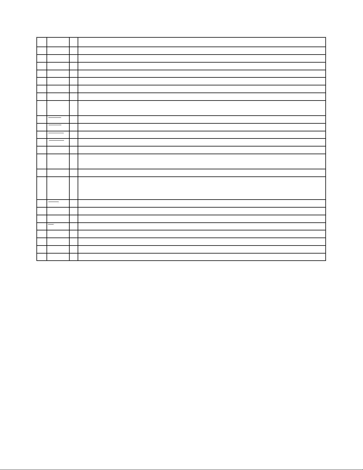
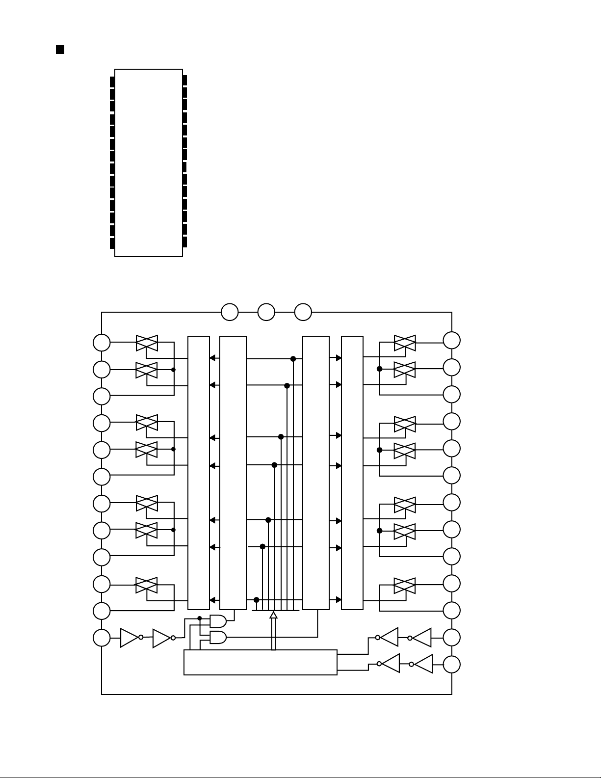
BU2092(IC402):PORT EXPANDER
1.Terminal Layout
RX-9010VBK
Vss
DATA
CLOCK
LCK
Q0
Q1
Q2
Q3
Q4
1
2
3
4
5
6
7
8
9
CONTROL
CIRCUIT
12BIT SHIFT RESISTER
12BIT STRAGE RESISTER
OUTPUT BUFFER(OPEN DRAIN)
18
17
16
15
14
13
12
11
10
Vdd
OE
Q11
Q10
Q9
Q8
Q7
Q6
Q5
2.Pin Function
Pin No.
1
2
3
4
5~16
17
18
Symbol
Vss
DATA
CLOCK
LCK
Q0~Q11
OE
Vdd
I/O
I
I
I
O
I
-
Function
Connect to GND
Serial Data input
Shift Clock of Data
Latch Clock of Data
Parallel Data Output
Latch Data L H
OUTPUT ON OFF
Output Enable
Power Supply
1-17
Page 18
RX-9010VBK
MB90088 (IC203) : On screen display controller
1.Terminal Layout
YIN
VIN
CIN
AVcc
IOUT
VOC
Vcc
EXS
XS
HSYNC
VSYNC
EXHSYN
EXVSYN
Vss
2.Block Diagram
SIN
SCLK
CS
EXHSYN
EXVSYN
1
2
3
4
5
6
7
8
9
10
11
12
13
14
28
AVss
27
YOUT
26
VOUT
25
COUT
24
CS
23
SIN
22
SCLK
21
TEST
20
BOUT
19
ROUT
18
GOUT
17
VOB
16
XD
15
EXD
Serial Input
Control
H/V Separate
Each Control, Data
VIN
YIN
CIN
HSYNC
VSYNC
XS
EXS
XD
EXD
NTSC/PAL
Signal OSC
Display Memory
Control
VRAM
4FSC CLK
OSC
Dot CLK
OSC
Each Block
Each Block
Analog SW
Video Signal
OSC
Output
Control
CGROM
VOUT
YOUT
COUT
BOUT
ROUT
GOUT
IOUT
VOC
VOB
1-18
Page 19
3.Functions
pin
Symbol I/O Function
no
YIN
1
2
3
4
5
6
7
8
9
10
11
12
13
14
15
16
17
18
19
20
21
22
23
24
25
26
27
28
VIN
CIN
AVcc
IOUT
VOC
Vcc
EXS
XS
HSYNC
VSYNC
EXHSYN
EXVSYN
Vss
EXD
XD
VOB
GOUT
ROUT
BOUT
TEST
SCLK
SIN
CS
COUT
VOUT
YOUT
AVss
I
Lux signal Input terminal for Superinpause indication
I
Composite video signal input terminal for Superinpause indication
Contrast signal input terminal for Superinpause indication
I
-
Analog power supply terminal
O
Color (Lux) signal output terminal
Character output terminal
O
Power supply terminal
Clock generater outside circuit terminal for color burst
I
O
O
Horizontal signal output terminal
O
Vertical signal output terminal
EXT horizontal signal input terminal
I
EXT vertical signal input terminal
I
GND
Dot clock generater outside circuit signal terminal for indication
I
O
Character & background signal output terminal
O
Color signal (Green, Red, Blue)
O
I
Test signal input terminal
Shift clock input terminal for serial transmission
I
Serial data input terminal
I
Chip select terminal
I
Contrast signal output terminal
O
Composite video signal output terminal
O
Lux signal output terminal
O
Analog GND terminal
-
RX-9010VBK
1-19
Page 20
RX-9010VBK
MAX4018ESD (IC390) : OP AMP.
ENA
ENC
ENB
Vcc
INA+
INA-
OUTA
N.C.
1
2
3
4
5
6
7
8
16
15
14
13
12
11
10
OUTC
INCINC+
V
EE
INB+
INBOUTB
N.C.
9
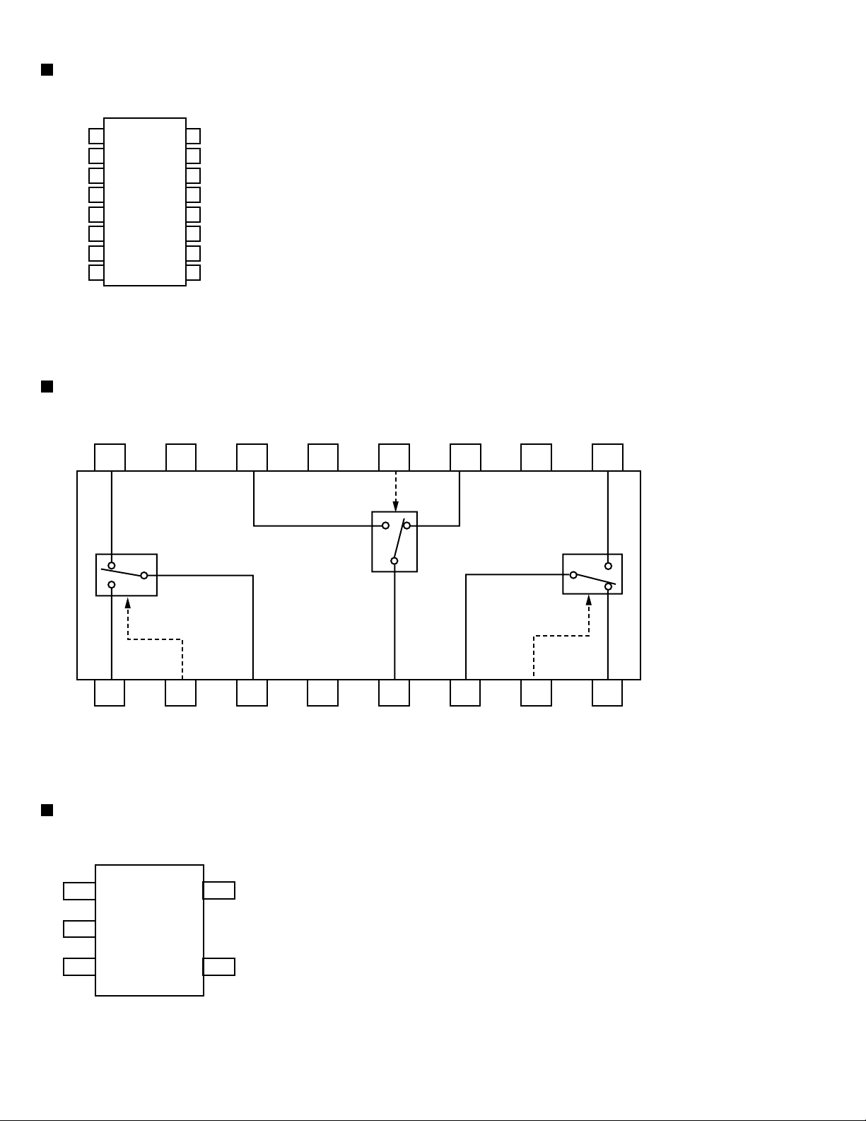
NJM2285V-W(IC202) : 2-INPUT 3CHANNEL VIDEO SWITCH
IN1A GND1 IN2B V CTL2 IN2A GND3 IN3B
16 15 14 13 12 11 10 9
BIAS TYPE
L
+
CLAMP TYPE
H
L
CLAMP TYPE
H
H
1 2 3 4 5 6 7 8
IN1B CTL1 OUT1 GND2 OUT2 OUT3 CTL3 IN3A
NJM2406F-X(IC387): SINGLE-SUPPLY COMPARATORS
1
5
2
3
4
PIN FUNCTION
1. -INPUT
2. GND
3. +INPUT
4. OUTPUT
+
5.V
L
1-20
Page 21
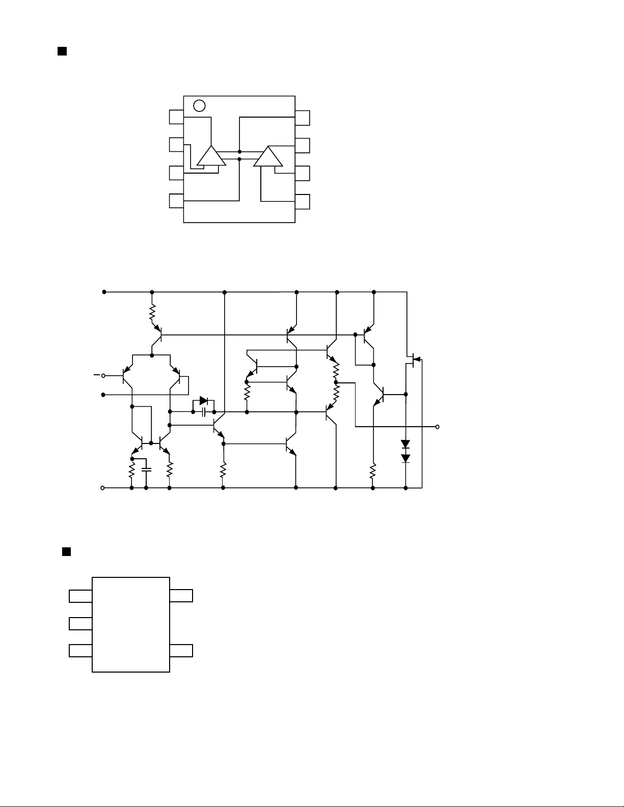
NJM4580D (IC301) : LPF, Mic and H.phone Amp.
1.Terminal layout
RX-9010VBK
2.Block diagram
+
V
INPUT
+
A OUT
A -IN
A +IN
V
1
2
A
3
-
4
(TOP VIEW)
B
8
7
6
5
+
V
B OUT
B -IN
B +IN
-
V
NJU7241F33(IC411) : VOLTAGE REGULATOR
PIN FUNCTION
1
5
2
3
4
1. GND
2. VIN
3. VOUT
4. +NC
5. STB
OUTPUT
1-21
Page 22
RX-9010VBK
PCM2702E-X (IC410) : DIGITAL / ANALOG CONVERTER
1.Pin layout
XTI
1
DD
C
V
2
DGNDC
3
DD
V
4
DGND
5
D+
6
D-
7
BUS
V
8
DGND
9
PLYBCK
10
SSPND
11
ZERO
12
TEST3
13
TEST2
14
3.Pin function
XTO
VccP
AGNDP
VccL
AGNDL
OUT
V
Vcc
COM
V
AGND
OUT
V
AGNDR
VccR
TEST0
TEST1
2. Block diagram
PLYBCK
28
27
26
25
24
L
23
22
21
20
R
19
18
17
16
15
D+
D-
VBUS
DGNDU
VDDC
DGNDC
SSPDN
USB I/F
MCLK
USB clock
generator
Crystal OSC
XTI
XTO
USB packet
data
WRCLK
FIFO
SPACT
audio
data
RDCLK
ZERO
8x
Oversampling
Digital Filter
System Clock
Audio clock
generator
DGNDP
VDDP
Multi-level
Delta-Sigma
Modulator
VccL
AGNDL
VccR
AGNDR
DAC
DAC
Power supply
VCC AGND VDD DGND
Low-pass
Filter
Low-pass
Filter
VOUTL
VCOM
VOUTR
PIN
1
2
3
4
5
6
7
8
9
10
11
12
13
14
15
16
17
18
19
20
21
22
23
24
25
26
27
28
Symbol
XTI
DD
C
V
DGNDC
DD
V
DGND
D+
D-
BUS
V
DGNDU
PLYBCK
SSPND
ZERO
TEST3
TEST2
TEST1
TEST0
VccR
AGNDR
OUT
R
V
AGND
COM
V
Vcc
OUT
L
V
AGNDL
VccL
AGNDP
VccP
XTO
I/O
IN
-
-
-
I/O
I/O
IN
-
OUT
OUT
OUT
IN
IN
IN
IN
-
-
OUT
-
-
-
OUT
-
-
-
-
OUT
Function
Crystal Oscillator Input.
Digital Power Supply for Clock Generator, +3.3V.
Digital Ground for Clock Generator.
Digital Power Supply, +3.3V.
Digital Ground.
USB Differential Input/Output Plus.
USB Differential Input/Output Minus.
USB Bus Power (This pin NEVER consumes the USB bus power).
Digital Ground for USB Transceiver.
Playback flag, active LOW. (LOW: playback, HIGH: idle).
Suspend flag, active LOW. (LOW: suspend, HIGH: operational).
Zero flag, (LOW: Normal, HIGH: ZERO).
Test pin 3. Connect to digital ground.
Test pin 2. Connect to digital ground.
Test pin 1. Connect to digital ground.
Test pin 0. Connect to digital ground.
Analog Supply for R-channel, +5V.
Analog Ground for R-channel.
Analog Output for R-channel.
Analog Ground.
Common for DAC.
Analog Supply, +5V.
Analog output for L-channel.
Analog Ground for L-channel.
Analog Supply for L-channel, +5V.
Analog Ground for PLL.
Analog Supply for PLL, +5V.
Crystal Oscillator Output.
(1)
(2)
(2)
(2)
(2)
(2)
1-22
Note:
(1) 3.3V tolerant.
(2) Schmitt trigger input with internal pull-down, 5V tolerant.
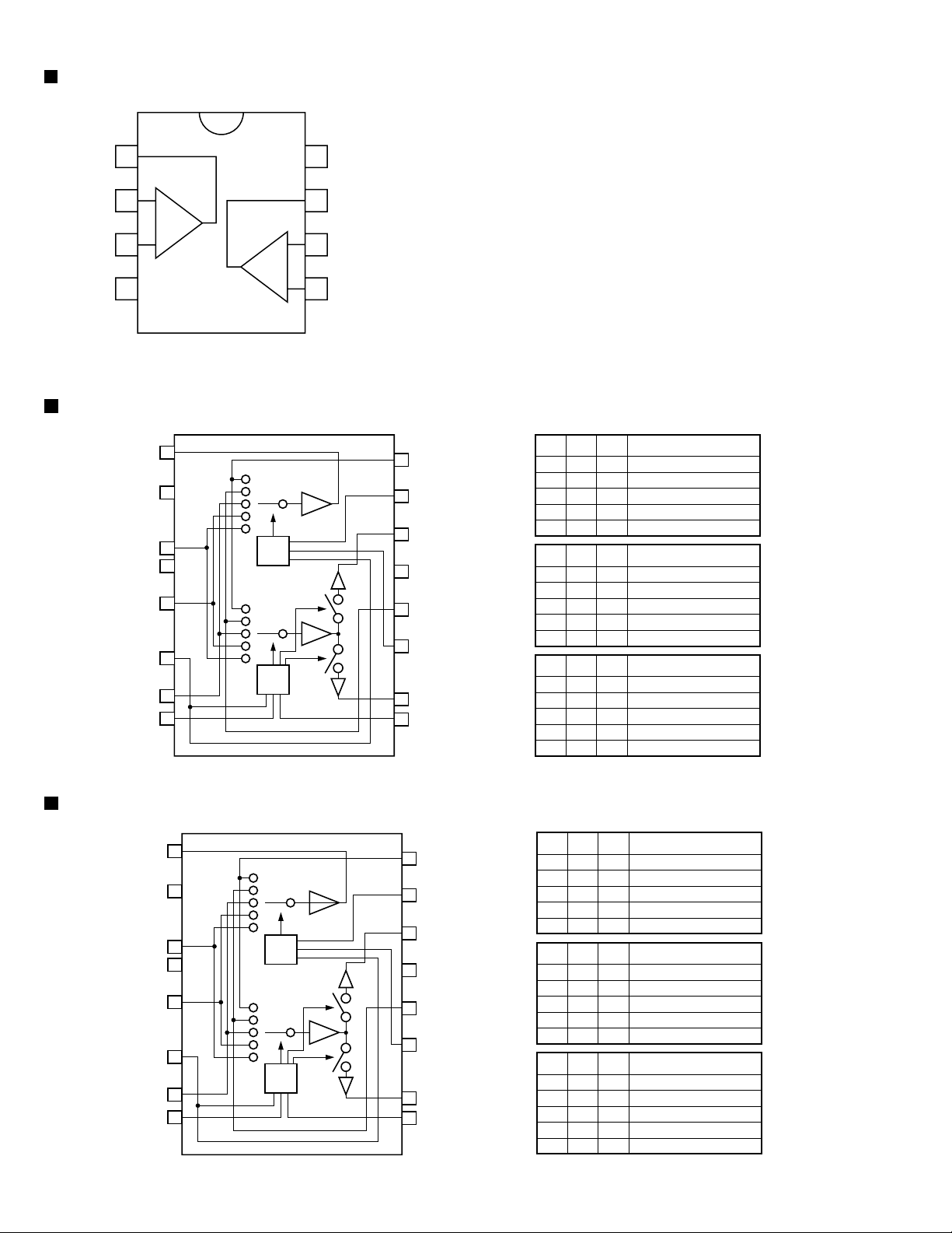
Page 23
TC9162AN (IC380) : ANALOG SWITCH
RX-9010VBK
VSS
L-S1
L-S2
L-COM1
L-S3
L-S4
L-COM2
L-S5
L-S6
L-COM3
L-S7
L-COM4
ST
GND
L-S1
1
2
3
4
5
6
7
8
9
10
11
12
13
14
2
28
27
26
25
24
23
22
21
20
19
18
17
16
15
VDD
R-S1
R-S2
R-COM1
R-S3
R-S4
R-COM2
R-S5
R-S6
R-COM3
R-S7
R-COM4
DATA
CK
VSS
GND VDD
1
14
28
27
R-S1
L-S2
L-COM1
L-S3
L-S4
L-COM2
L-S5
L-S6
L-COM3
L-S7
L-COM4
ST
10
11
12
13
26
25
24
23
22
21
20
19
18
17
16
R-S2
R-COM1
R-S3
R-S4
R-COM2
R-S5
R-S6
R-COM3
R-S7
R-COM4
DATA
3
4
5
6
7
8
LEVEL SHIFTER
9
LATCH CIRCUIT
LATCH CIRCUIT
LEVEL SHIFTER
SHIFT REGISTER
15
CK
1-23
Page 24

RX-9010VBK
TC9163AF-X (IC371, IC392) : ANALOG SWITCH
VSS
L-S1
L-S2
L-S3
L-COM1
L-S4
L-S5
L-S6
L-COM2
L-S7
L-S8
L-COM3
ST
GND
L-S1
L-S2
1
2
3
4
5
6
7
8
9
10
11
12
13
14
2
3
28
27
26
25
24
23
22
21
20
19
18
17
16
15
VDD
R-S1
R-S2
R-S3
R-COM1
R-S4
R-S5
R-S6
R-COM2
R-S7
R-S8
R-COM3
DATA
CK
VSS
GND VDD
1
14
28
27
26
R-S1
R-S2
L-S3
L-COM1
L-S4
L-S5
L-S6
L-COM2
L-S7
L-S8
L-COM3
ST
10
11
12
13
4
5
6
7
8
9
LEVEL SHIFTER
LATCH CIRCUIT
LATCH CIRCUIT
LEVEL SHIFTER
SHIFT REGISTER
25
24
23
22
21
20
19
18
17
16
15
R-S3
R-COM1
R-S4
R-S5
R-S6
R-COM2
R-S7
R-S8
R-COM3
DATA
CK
1-24
Page 25

TC9164AF-X (IC302, IC391) : ANALOG SWITCH
RX-9010VBK
VSS
L-S1
L-S2
L-S3
L-S4
L-COM1
L-S5
L-S6
L-COM2
L-S7
L-S8
L-COM3
ST
GND
L-S1
L-S2
1
2
3
4
5
6
7
8
9
10
11
12
13
14
2
3
28
27
26
25
24
23
22
21
20
19
18
17
16
15
VDD
R-S1
R-S2
R-S3
R-S4
R-COM1
R-S5
R-S6
R-COM2
R-S7
R-S8
R-COM3
DATA
CK
VSS
GND VDD
1
14
28
27
26
R-S1
R-S2
L-S3
L-S4
L-COM1
L-S5
L-S6
L-COM2
L-S7
L-S8
L-COM3
ST
10
11
12
13
25
24
23
22
21
20
19
18
17
16
15
R-S3
R-S4
R-COM1
R-S5
R-S6
R-COM2
R-S7
R-S8
R-COM3
DATA
CK
4
5
6
7
8
LEVEL SHIFTER
9
LATCH CIRCUIT
LATCH CIRCUIT
LEVEL SHIFTER
SHIFT REGISTER
1-25
Page 26

RX-9010VBK
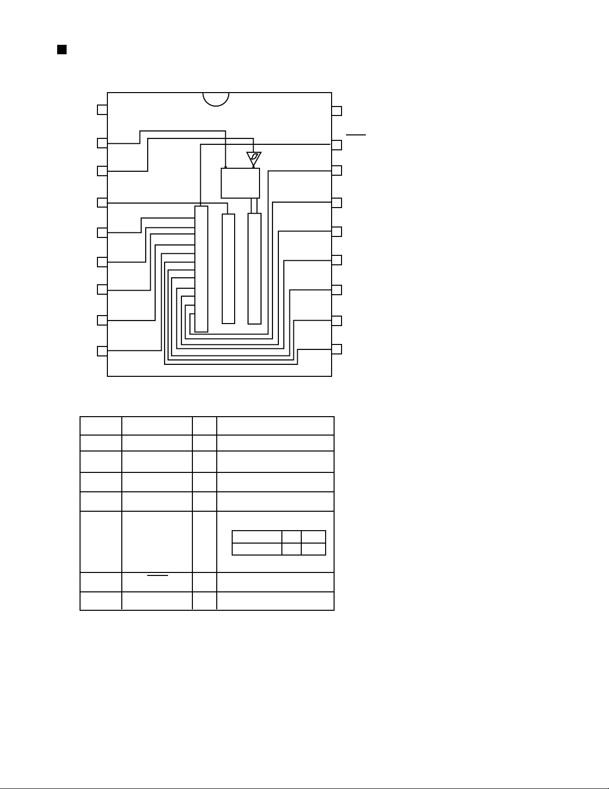
TC9459F (IC381, IC382, IC383, IC393) : Electronic volume control
1.Terminal layout
VSS
L-OUT
NC
L-ch
L-IN
L-LD1
L-LD2
L-A-GND
NC
CS1
NC
GND
CK
2. Block diagram
VSS
1
1
2
3
4
5
6
7
8
9
10
11
12
24
23
22
21
20
19
18
17
16
15
14
13
VDD
R-OUT
NC
R-IN
R-LD1
R-LD2
R-A-GND
NC
CS2
NC
STB
DATA
R-ch
L-OUT
NC
L-1N
L-LD1
L-LD2
L-A-GND
NC
CS1
NC
GND
CK
9
10
11
12
2
3
4
5
6
7
8
50k /
915TEP
VR
L-ch 7 to 91
decoder
L-ch data
latch circuit
Shift register (24BIT)
Level shift circuit
VDD
24
Same as L-ch
Circuit
R-ch 7 to 91
decoder
R-ch data
latch circuit
23
22
21
20
19
18
17
16
15
14
13
R-OUT
NC
R-IN
R-LD1
R-LD2
R-A-GND
NC
CS2
NC
STB
DATA
3.Pin function
Pin No.
1
2
3
4
5
6
7
8
9
10
11
12
Symbol
VSS
L-OUT
NC
NC
L-LD1
L-LD2
L-A-GND
NC
CS1
NC
NC
CK
Function
Negative power supply pin
Volume output pin
No connection
No connection
Loudness tap output pin
Loudness tap output pin
Analog GND pin
No connection
Chip select input pin
No connection
No connection
Clock input pin
Pin No.
13
14
15
16
17
18
19
20
21
22
23
24
Symbol
DATA
STB
NC
CS2
NC
R-A-GND
R-LD2
R-LD1
R-IN
NC
R-OUT
VDD
Function
Data input pin
Strobe input pin
No connection
Chip select input pin
No connection
Analog GND pin
Loudness tap output pin
Loudness tap output pin
Volume input pin
No connection
Volume output pin
Positive power supply pin
1-26
Page 27

PQ3DZ53 (IC583) : Regulator IC
RX-9010VBK
DC INPUT(Vin)
1
CUSTOM IC
5
GND
TC74HC4053AF (IC388, IC389) : MULTIPLEXER
1Y
0Y
Z-COM
0Z
INH
EE
V
GND
1
2
IZ
3
4
5
6
7
8
16
15
14
13
12
11
10
9
Vcc
Y-COM
X-COM
1X
0X
A
B
C
CONTROL INPUTS
INHIBIT
L
L
L
L
L
L
L
L
H
X: Don't Care.
3
DC OUTPUT(Vo)
ON/OFF CONTROL(Vc)
2
C
B
A
L
L
K
L
L
H
L
H
K
L
H
H
H
L
K
H
L
H
H
H
K
H
H
H
X
X
X
W24L010AJ-12 (IC511) : CMOS STATIC RAM
1. Pin layout
1
A11
2
A9
3
A8
4
A13
5
WE
6
CS2
7
A15
8
VDD
9
NC
10
A16
11
A14
12
A12
13
A7
14
A6
15
A5
16
A4
NC
A16
A14
A12
I/O1
I/O2
I/O3
Vss
1
2
3
4
5
A7
6
A6
7
A5
8
A4
9
A3
10
A2
11
A1
12
A0
13
14
15
16
32-pin
TSOP
V
DD
32
A15
31
CS2
30
WE
29
A13
28
A8
27
A9
26
A11
25
OE
24
A10
23
CS1
22
I/O8
21
I/O7
20
I/O6
19
I/O5
18
I/O4
17
32
OE
31
A10
30
CS1
29
I/O8
28
I/O7
27
I/O6
26
I/O5
25
I/O4
24
Vss
23
DO3
22
DO2
21
DO1
19
A0
18
A1
17
A2
16
A3
2. Block diaglam
DD
V
Vss
A0
DECODER
A16
CS2
CS1
CONTROL
OE
WE
3. Pin function
SYMBOL
A0 - A16
I/O1 - I/O8
CS1, CS2
WE
OE
DD
V
Vss
NC
CORE
ARRAY
DATA I/O
I/O1
I/O8
DESCRIPTION
Address Input
Data Input/Output
Chip Select Inputs
Write Enable Input
Output Enable Input
Power Supply
Ground
No Connection
1-27
Page 28

RX-9010VBK
UPD784215AGC132(IC581) : UNIT CPU
1.Pin layout
75 ~ 51
76
~
50
~
100
1 ~ 25
26
2.Pin function
Pin No. Symbol I/O Function
1~8
9
10
11
12
13
14
15
16
17
18
19~22
23
24
25~32
33
34,35
36
37,38
39
40
41
42
43
44
45,46
47
48
49
50,51
52
53
54
55
56
57~63
64,65
66
67
68~70
71
72
73~75
76
77
78
79,80
81
82,83
84
85
86
87
88
89~93
94
95~100
VDD
X2
X1
VSS
XT2
XT1
RESET
AUTO
ERR
Fz96k
P03~P06
AVDD
AV REF0
P10~P17
AVSS
P130, P131
AV REF1
RX, TX
DSPCOM
DSPSTS
DSPCLK
DSPRDY
MIDIO_IN/OUT
MICK
HREQ
SS
DSP_RST
D_CS
PD/ DIR
CDTI/CDTO
CCLK
CS
PD
GND
EQ
CTR TONE
3D
VDD
ANA_TT
LEF_MIX
LEF_OUT
MIX_OUT
S_MUTE
TEST
Non connect
Power supply terminal
Connecting the crystal oscillator for system main clock
Connecting the crystal oscillator for system main clock
I
Connect to GND
Connecting the crystal oscillator for system sub clock
Connect VSS
I
System reset signal input
I
Output of DSP to general-purpose port
I
Output of DSP to general-purpose port
I
Output of DSP to general-purpose port
I
Output of DSP to general-purpose port
I
Power supply terminal
Connect to GND
Connect to GND
Connect to GND
Non connect
O
Power supply terminal
Not use
O
Non connect
O
Communication port from IC901
I
Status communication port to IC901
O
Clock input from IC901
I
Ready signal input from IC901
I
Non connect
O
Interface I/O terminal with microcomputer
I/O
Interface I/O terminal with microcomputer of clock signal
O
HREQ
I
System slave select
O
Non connect
Reset signal output of DSP
O
Non connect
Chip select output
O
Non connect
Reset signal output
O
Non connect
Interface I/O terminal with microcomputer
O/I
Interface I/O terminal with microcomputer of clock signal
O
CS
O
Non connect
Reset signal output
O
Connect to GND
Non connect
EQ
O
CENTER TONE
O
3D-Phonic
O
Non connect
Power supply
Non connect
Analog./T.TONE
O
Select 1
O
Select 2
O
Select 3
O
S.MUTE
O
Non connect
Test terminal
Non connect
-
1-28
Page 29

LC72136N (IC121) : PLL frequency synthesizer
1. Pin layout
FM/AM
CLOCK
FM/ST/VCO
AM/FM
2. Block diagram
XT
CE
DI
DO
SDIN
1
2
3
4
5
6
7
8
9
10
11
22
21
20
19
18
17
16
15
14
13
12
XT
GND
LPFOUT
LPFIN
PD
VCC
FMIN
AMIN
IFCONT
IFIN
RX-9010VBK
1
22
16
15
3
4
5
6
17
21
3. Pin function
Pin
Symbol
No.
1
2
3
4
5
6
7
8
9
10
11
XT
FM/AM
CE
DI
CLOCK
DO
FM/ST/VCO
AM/FM
LW
MW
SDIN
Reference
Driver
Swallow Counter
1/2
C
2
B
I/F
Power
on
Reset
Function
I/O
X'tal oscillator connect (75kHz)
I
LOW:FM mode
O
When data output/input for 4pin(input) and
I
Swallow Counter
1/16,1/17 4bit
1/16,1/17 4bit
12bit
Programmable
DriverS
Data Shift Register & Latch
7821113
6pin(output): H
Input for receive the serial data from
I
controller
Sync signal input use
I
Data output for Controller
O
Output port
"Low": MW mode
O
Open state after the power on reset
O
Input/output port
I/O
Input/output port
I/O
Data input/output
I/O
Phase
Detector
Charge Pump
Unlock
Detector
Universal
Counter
Pin
No.
12
IFCONT
13
14
15
16
17
18
19
LPFOUT
20
21
22
Symbol
IFIN
AMIN
FMIN
VCC
PD
LPFIN
GND
XT
18
19
20
12
I/O
Function
IF counter signal input
I
IF signal output
O
Not use
-
AM Local OSC signal output
I
FM Local OSC signal input
I
Power suplly(VDD=4.5-5.5V)
When power ON:Reset circuit move
PLL charge pump output(H: Local OSC
O
frequency Height than Reference frequency.
L: Low Agreement: Height impedance)
Input for active lowpassfilter of PLL
I
Output for active lowpassfilter of PLL
O
Connected to GND
X'tal oscillator(75KHz)
I
1-29
Page 30

RX-9010VBK
LA1838(IC102): FM AM IF AMP&detector, FM MPX decoder
1. Block Diagram
30
ALC
BUFF
FM
S-METER
FM IF
1
2. Pin Function
Pin
Symbol
No.
FM IN
1
AM MIX
2
3
FM IF
AM IF
4
GND
5
6
TUNED
STEREO
7
8
VCC
9
FM DET
10
AM SD
FM VSM
11
AM VSM
12
13
MUTE
14
FM/AM
MONO/ST O
15
29
28
AM
OSC
SD
COMP
S-CLRVE
PM
DET
2
I/O
I
This is an input terminal of FM IF
REG
AM
MIX
AM/FM
IF-BUFF
3
27
FM
RF.AMP
AM IF
4
26
AGC
AM
S-METER
GND
Function
DET
5
signal.
This is an out put terminal for AM
O
mixer.
I
Bypass of FM IF
Input of AM IF Signal.
I
I
This is the device ground terminal.
When the set is tuning, this terminal
O
becomes "L".
O
Stereo indicator output. Stereo "L",
Mono: "H"
III
This is the power supply terminal.
I
FM detect transformer.
I
This is a terminal of AM ceramic filter.
O
Adjust FM SD sensitivity.
O
Adjust AM SD sensitivity.
I/O
When the signal of IF REQ of IC121(
LC72131) appear, the signal of FM/AM
IF output. //Muting control input.
Change over the FM/AM input.
I
"H" :FM, "L" : AM
Stereo : "H", Mono: "L"
25
TUNING
DRIVE
6
24
STEREO
DRIVE
7
22
23
VCC
89
Pin
Symbol
No.
16
L OUT
17
R OUT
18
19
20
21
22
23
24
25
26
27
28
29
30
L IN
R IN
RO
LO
IF IN
FM OUT
AM DET
AM AGC
AFC
AM RF
REG
AM OSC
OSC BUFFER
P-DET
VCO
384KHz
21
DECODER
ANIT-BIRDIE
10
I/O
O
O
I
O
O
I
O
O
I
I
O
O
20
STEREO
5N
SW
FF
38k
11
18
19
MUTE
FF
/
19k
2
12 13
FF
19k
17 16
/
LS
14
PILOT
DET
15
Function
Left channel signal output.
Right channel signal output.
Input terminal of the left channel post
I
AMP.
Input terminal of the right channel
post AMP.
Mpx Right channel signal output.
Mpx Left channel signal output.
Mpx input terminal
FM detection output.
AM detection output.
This is an AGC voltage input terminal
for AM
I
This is an output terminal of voltage
for FM-AFC.
AM RF signal input.
Register value between pin 26 and pin28
desides the frequency width of the
input signal.
I
This is a terminal of AM Local
oscillation circuit.
AM Local oscillation Signal output.
1-30
Page 31

RX-9010VBK
VICTOR COMPANY OF JAPAN, LIMITED
AUDIO & COMMUNICATION BUSINESS DIVISION
PERSONAL & MOBILE NETWORK BUSINESS UNIT. 10-1,1chome,Ohwatari-machi,Maebashi-city,371-8543,Japan
(No.20921)
Printed in Japan
200103(V)
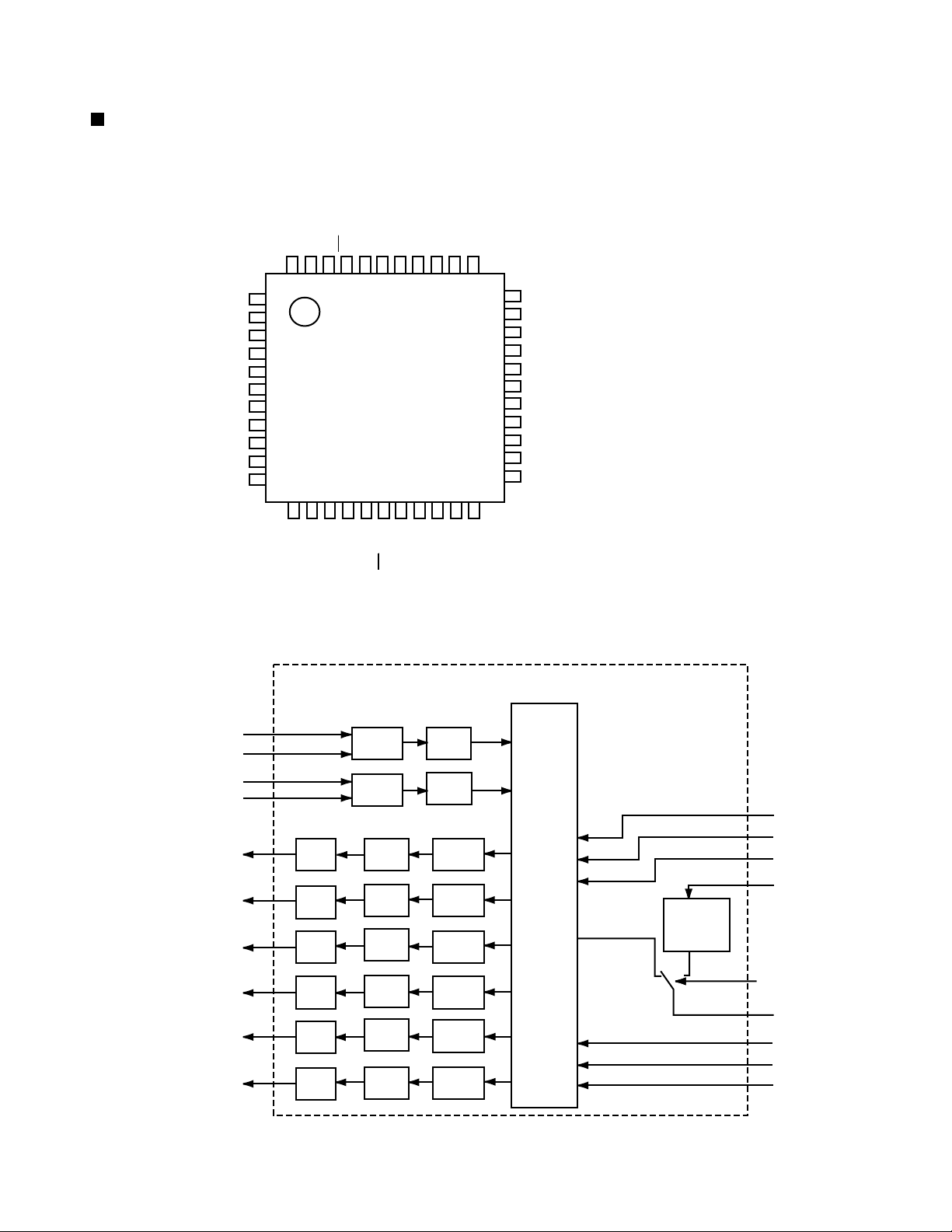
Page 32

Block diagrams
Signal I/O block section
RX-9010VBK
Main section
CN406
SYSTEM CONTROL
5
& FL
COMP LINK
TEXT LINK
CN731 CN732
L ch
L/R
CEN
ROOM
CEN
REAR/ SUB
IC382
IC384
IC383
REAR
R ch
LVA10220-2
CN243
MON
MON
IC381
LVA10222-1
CN240
CN244 CN242
S Video
LVA10219-5
4
CN200 CN204 CN206
L/R
Video
LVA10219-4
DATA
CEN
L/R
CN587 CN581
3
CPU
IC901
CN313 CN371 CN416
REAR
DSP
LVA10223
CN501 CN205
CN381
V Audio input
LVA10219-3
2
DATA
CN311 CN351
CN361
VOL DATA/ CLK
MAIN ROOM SIGNAL
SUB ROOM SIGNAL
MAIN ROOM SIGNAL
DATA/ CLK
IC380
DVD CENTER
DVD REAR
SW
IC387
DVD
SUB WOOFER
IC386
DVD
SUB WOOFER
DVD
CENTER
CEN
CN722
LVA10220-1
Q761
Q763
Q762
Q764
LVA10220-3
Q1751
Q1752
LVA10220-4
CN711
CN712
CN713
CN701
CN702
R
CN721
L
CEN
CN703
SL
SR
CN723
LVA10221-1
CN813
CN814CN881
CN823
CN824
RY831
RY832
ROOM
RY851
RY852
LVA10221-2
SUB
RY833
L
SPK1
R
L
SPK2
/SUB
R
ROOM
SPK
CENTER
REAR L
REAR R
Audio input
& FL
FW481
CN412
SYSTEM CONTROL
& FL
LVA10219-2
CN101 CN301 CN303 CN601 CN201 CN241
1
CN400
CN111
Tuner
LVA10009
CN406
SYSTEM CONTROL
CN480
LVA10219-1
RF MODULE
RL ch
RR ch
Q1851
Q1853
Q1852
Q1854
CN715
CN716
CN705
FW881
LVA10222-7
CN706
LVA10220-5
CN410
SYSTEM
CONTROL
& FL
ABCD E F G
2-1
Page 33

RX-9010VBK
Video section
IC 203
LVA10219-4
DATA
CN200CN204CN206
DVD
TV/DBS
5
MON Y/C OUT
MON Y/C IN
VCR1
VCR2
R
SW
P
R
P
IC 201
Y/C SEP
IC 202
V SIG
4
FRONT VIDEO
IN (RCA)
MON
S Video section
3
LVA10219-5
V Audio input section
DVD F
TV/DBS
VCR1 REC
VCR1 P.B
VCR2 REC
VCR2 P.B
SUB PRE
OUT
SOUTCE
SELECTOR
IC 371
SOUTCE
SELECTOR
IC 392
MAIN ROOM SIG
SUB
DATA/
CLK
ROOM SIGNAL
SUB ROOM
ROOM
REAR/ SUB
REAR SIG
SIG
SUB
SIG
LVA10219-3
DATA/CLK
SUB
DATA/CLK
IC 394
IC 393
IC 395
MAIN ROOM SIG
SUB ROOM
IC372
FRONT VIDEO
CN313
CN371
SIG
USB
CN416
DATA
CN240
C
DVD
IC 241
SW
(C)
DSP section
VCR1
VCR2
TV/DBS
MON
LVA10223
R
P
R
P
IC 242
SW
(Y)
Y
C
FRONT Y/C
Y
MON Y/C
MON Y/C
CN244
CN242
DIGITAL
IN1
DIGITAL
IN2
DIGITAL
IN3
DIGITAL
IN4
DIGITAL
OUT
SELECTOR
IC 551
DSP
CONTROLLER
IC 581
DSP
IC 501
DATA
AD/DA
CONVERTER
IC 571
SD RAM
IC 511
CN587
R/L
C
SR/SL
CN581
2
1
2-2
HABC DEFG
Page 34

RX-9010VBK
Audio input section
LVA10219-2
PHONO
5
L/R
EQ
IC 301
System control & FL section
LVA10218-1
FL DISPLAY D400
CN412
CD
L/R
TAPE
P.B
TAPE
4
REC
CDR
P.B
CDR
REC
SOURCE
SELECTOR
IC 302
MAIN ROOM SIGNAL
DATA/CLK
TUNER
SUB DATA/ CLK
VOL
DATA/
CLK
IC 303
AUDIO
CN311
KEY
SYSTEM CONTROLLER
IC 400
Y/C
VIDEO
CN410
CN351
AUDIO
CN406
USB
3
SOURCE
SELECTOR
IC 391
SUB ROOM SIGNAL
2
DVD
REAR
IC 304
DVD REAR
Tuner section
FM
TUNER
RF 101
LVA10009
AM/FM DET
IC102
TUNER
AM
1
MW RF & OSC
T111
ABCD E F G
PLL
IC102
DATA
CN111
2-3
Page 35

Standard schematic diagrams
Power supply section
5
RX-9010VBK
131
RY63RY62
QSK0088-001QSK0088-001
CN811
D67
1SS133
4
F61
F62
3.3
R61
CN55
CN56
132
113
112
111
123
122
121
134
133
sheet 10/11
CN402
C69
0.047MY
FW51
PW10
PW11
PW12
PW13
PW14
PW15
PW16
PW28
PW29
PW40
PW20
PW17
PW26
PW18
PW19
PW30
R1
3.3M
F1
TA1
TA2
3
C51
C52
1000/25
T2
QQT0281-005
D52
D54
1SR35-400A
D57
1SR35-400A
1SS133
R53
6.8
C1
0.0047
RY1
QSK0098-001
R54
Q53
KRC105M
820
470/16
C44
Q42
KTD863/Y/
C45
0.0047
D46
MTZ6.2JA
Q52
KTD863/Y/
C55
C54
470/16
0.0047
D56
MTZ6.2JB
820
R44
C68
0.047MY
R74
100K
Q61
KRC105M
CN72
CN71
2
C74
sheet 3/11
CN82
CN491
1/50
D75
MTZ8.2JC
12
R67
Q74
KTC3200/GL/
Q71
KTA1046/Y/
C73
22/50
R73 D74 C72
MTZ33JC
22K
D61
10E2-FD
D63
10E2-FD
3.3k
R72
22/50
1SR35-400A
D62
C63
0.1MY
C65 C66
3300/35 1000/35
D73
C70
C71
100/63
220/50
D71
1SR35-400A
D72
1SR35-400A
1SR35-400A
C62C61
0.1MY0.1MY
D64
1SR35-400A
TH71
QAD0095-4R7
D51
1SR35-400A
D53
1SR35-400A
0.0047/100
TO FW481
sheet 6/11
EP51
SHEET
1
NUMBER
1/11
POWER SUPPLY
2/11
MAIN
3/11
AUDIO
4/11
AUDIO SIGNAL INPUT
5/11
VIDEO SIGNAL INPUT
6/11
VOLUME COMPONENT
7/11
AUDIO AMP (FRONT CHANNEL)
8/11
AUDIO AMP (CENTER, REAR CHANNEL)
9/11
DSP
10/11
SYSTEM CONTROL
11/11
TUNER
CIRCUIT DESCRIPTION
2-4
Parts are safety assurance parts.
When replacing those parts make
sure to use the specified one.
SHEET 1/11
HABC DEFG
Page 36

5
4
3
2
Main & Speaker terminal section
CN703
C801
D801
30DF2-FC
D803
C807C808
100K100K
6800/716800/71
R801R802
CN801
sheet 1/11
30DF2-FC
C805
C802
D802
30DF2-FC
D804
30DF2-FC
CN701
C816
47/25
D816
MTZ18JC
R816
3.3k
FRONT Signal
CENTER Signal
REAR Signal
RX-9010VBK
C845
C833
220p
sheet 8/11sheet 8/11sheet 8/11 sheet 7/11 sheet 7/11sheet 6/11 sheet 6/11
CN721
12
R815
Q811
3.3K
R812
Q812
KTC3200/GL/
2SD2395/EF/
D811
R814
10k
47k
R813
R811
C811
0.0047
CN702
MAIN ROOM
CN705
Parts are safety assurance parts.
CN723
10/25
C824
R826
Q825
KTA1268/GL/
10K
R825
100K
R824
Q824
R823
10K
130K
KTC3200/GL/
Q823
47/16
KTC3199/GL/
C823
sheet 3/11
CN831
R841
R842
R843
R844
R845
CN706
1SS133
D825
CN823
CN813
L844
0.45
B124
L845
0.45
B125
L843
0.45
CN824
B123
RY871
QSK0109-001
CN881
FW881
R91
470
R92
CN814
470
C91
C92
470P470P
100K
82K
100K
100K
82K
12
R871
D871
1SS133
RY831
R831
12
D831
1SS133
R832
12
D832
1SS133
RY832
R835
12
D835
RY833
R851
12
1SS133
RY851
D851
R852
12
1SS133
RY852
D852
J91
FW931
1SS133
C835
0.022
R885
C885
0.1
R888
C888
0.1
C887
0.1
R887
When replacing those parts make
sure to use the specified one.
sheet 3/11
0.022
R833
10
220P
C834
0.022
220P
C836
0.022
10
C842 C841
R834
C846
220P
C847
220P
1010
R837R838
C837
0.022
C839
0.022
C838
0.022
220P
C848
C891
220P
10
220P
C886
220P
10
C890
C892
220P
220P
10
C889
C893
220P
C850
4.7/50
D841
MTZ5.1JC
3.9K
R855
D845
1SS133
D846
1SS133
R867
10K
220P220P
C843
C844
C881
220p
C883
220p
C840
C884
220p
S831
Q833
KRC109M
0.022
Q830
KRC109M
R865
4.7K
ST831
ST851
22K
D843
1SS133
D844
1SS133
D842
1SS133
22K
22K
R862
R859
R856
R857
6.8K
R860
R863
6.8K
6.8K
R864
4.7K
Q831
KRC109M
4.7K
4.7K
R861
R858
Q832
KRC109M
C852
C851
C853
4.7/504.7/504.7/50
R866
4.7K
Q835
KRC109M
KRC109M
Q836
Q834
KRC109M
SUB ROOM Signal
1
SHEET 2/11
ABCD E F G
2-5
Page 37

Audio section
RX-9010VBK
R915
R916
8.2
8.2
5
R971
0.0047
C972
R973
12
3.3K
Q951
2SD2395/EF/
C951
100/25
D951 D961
MTZ13JC
2SD2395/EF/
C971
100/25
Q971
D971
MTZ10JC
C952
0.0047
R951
R953
12
2.2K
C961
100/25
Q961
KTA1046/Y/
MTZ13JC
4
CN301
220
R944
R945
R946
R947
R948
R949
R954
R955
R956
220
220
220
220
220
220
220
220
R940
4.7
sheet 4/11
CN303
MAIN_STB
MAIN_CLK
MAIN_DAT
SUB_STB
SUB_CLK
SUB_DAT
-15V
+15V
VOL_STB
VOL_CLK
VOL_DAT
3
sheet 4/11
2
sheet 11/11
sheet 11/11
SUBV_STB
SUB_PRE
SUB_MUTE
S_MUTE
SW_MUTE
CN101
TUNER_DATA
TUNER_CE
TUNER_CK
TUNER_MUTE
TUNED
STEREO
CN102
RDS_ST
RDS_DATA
RDS_CLK
R936
R935
R934
R937
R938
R939
R999
10K
22
R975
C975
470/6.3
FL991
220
220
220
220
220
220
QQR0590-001
0.0056
FL992
QQR0590-001
C991
0.0056
C992
R991
R992
4.7K
4.7K
R908
DVD_S/C
DBS_S/C
VCR1_S/C
VCR2_S/C
CN201
VIDEO1
VIDEO2
VIDEO3
VIDEO4
OSD_CS
OSD_DAT
OSD_CLK
VIDEO5
VIDEO6
CN241
C985
0.01
Q901
KRC107M
22K
0.0047
C962
D904
1SS133
R910
R961
12
R963
2.2K
IC903
IC-PST9139
R911
4.7K
C904
2.2/50
22k
220
220
220
220
R927
R928
R925
R926
DSPCLK
DSPREADY
DSPSTATUS
DSPCOMMAND
CN601
220
R929
DSPRESET
MTZ5.6JC
R903
C903
2SD2395/EF/
C941
100/25
D941
330
2200/6.3
C905
0.022
C994
270P
Q941
R976
R978
R993
R995
R997
100/6.3
C901
4.7K
6.2K
13K
15K
0.0047
4.7K
1.5
C902
C942
X901
D975
4.7K
R977
D976
1SS133
8MHz
R943
2.7K
4.7K
5.1K
R994
R979
D977
OSD_DAT
OSD_CS
OSD_CLK
M_COMMAND
M_STATUS
R941
33
R942
3.3K
R996
D978
M_CLK
33
5.6K
R998
D979
M_RESET
M_CS
C921
100/25
TUNED
M_BUSY
MTZ5.6JC
STEREO
RDS_ST
Q921
2SD2395/EF/
D921
PROTECT
4/8_IN
C922
0.0047
TUNER_MUTE
TUNER_DATA
C993
100P
IC901
MN101C49GHM
TUNER_CK
TUNER_CE
RDS_DATA
RDS_CLK
D993
1SS133
R921
R923
2.7K
33
R922
33
4/8_OUT
D903
1SR35-400A
STANDBY_LED
DSPRESET
D902
1SR35-400A
10K
10K
10K
R967
R965
R966
VCR1_S/C
DVD_S/C
DSPSTATUS
DSPCOMMAND
C931
100/25
D901
10K
10K
R969
R968
DBS_S/C
VCR2_S/C
DSPCLK
DSPREADY
D931
MTZ6.2JC
1SR35-400A
VIDEO6
VIDEO_S/C
S_MUTE
SW_MUTE
Q931
2SD2395/EF/
D900
1SR35-400A
R924
0.0047
10K
C932
KRC105M
VIDEO5
SUB_MUTE
SUB_PRE
SUB_RELAY
SUR_RELAY
C_RELAY
F2_RELAY
F1_RELAY
HP_RELAY
SUBV_STB
SUB_DAT
SUB_CLK
SUB_STB
MAIN_DAT
MAIN_CLK
MAIN_STB
VOL_DAT
VOL_CLK
VOL_STB
VIDEO4
VIDEO3
VIDEO2
VIDEO1
Q908
PROTECT
HP_RELAY
F1_RELAY
F2_RELAY
SUB_RELAY
C_RELAY
SUR_RELAY
4/8_OUT
4/8_IN
R933
2.7K
R931
R932
R917
10
CN81
FW831
sheet 2/11
CN400
220
R930
R980
R981
R982
R983
R984
R985
R986
R987
10K
Q907
220
220
220
220
220
220
220
Q906
KRC105M
330P
C981
Q905
KRC105M
330P
C982
KRC105M
C983
Q904
330P
KRC105M
M_CLK
M_COMMAND
M_STATUS
M_CS
M_BUSY
M_RESET
STANDBY_LED
VCR_S/C
330P
C984
Q903
KRC105M
CN931
CN932
sheet 10/11
EP901
sheet 2/11
1
sheet 6/11sheet 5/11sheet 5/11
TUNER Signal
Parts are safety assurance parts.
When replacing those parts make
sure to use the specified one.
SHEET 3/11
2-6
HABC DEFG
Page 38

Audio / V Audio signal input section
RX-9010VBK
C301
R301
2.2k
4.7/50
5
C302
R302
2.2k
4.7/50
C333
R333
470 470
R323
470
R325
470
R327
470
R329
CDR.REC-L
4
CDR.PLAY-L
470
R331
470
C361
4.7/50
100k100k
R363R364
R361R362
C362
4.7/50
390p
C321 C322
220p
C323 C324
220p
C325 C326
220p
C327 C328
220p
C329 C330
220p
C331 C332
220p
100k100k
BA15218F
IC304
BA15218F
IC304
C334
R334
390p
REC-RREC-L
PLAY-RPLAY-L
CDR.REC-R
CDR.PLAY-R
J301
CD-RCD-L
J302
J303
220p
R324
470
220p
R326
470
220p
R328
470
220p
R330
470
220p
R332
470
220p
C363
4.7/50
R365R366
100k100k
C364
4.7/50
100p100p
C303
C304
DVD-LS
DVD-RS
R305
C309C310
47k47k
R303R304
100p100p
620
NJM4580DD
100/10
C314 C313
100/10
R306
620
R335
68
C335
22/25
IC302
TC9164AF-X
C336
22/25
R336
68
IC301
IC301
NJM4580DD
C305 C307
R307 R309
C306 C308
R308 R310
CD-R
CDR.PLAY-R
PLAY-R
CD-L
PLAY-L
CDR.PLAY-L
0.0018MY 0.0068MY
39k 470k
0.0018MY
39k 470k
V.SIG.R
V.SIG.L
TUNER-R
TUNER-L
0.0068MY
REC-R
REC-L
C311
4.7/50
C312
4.7/50
100k100k
R311R312
CDR.REC-R
CDR.REC-L
47/1647/16
C315C316
C339
560p
CN351
QGB1214K1-16S
R315
330
R316
330
IC303
BA15218F
V.SIG.L
V.SIG.R
C1202
DVD-LS
C1201
22/25
22/25
DVD-RS
R1201
68
IC391
R1202
68
VOL_STB
VOL_CLK
TC9164AF-X
VOL_DATA
C341
10/50
R343
100k100k
R341R342
SUB-R
CDR.PLAY-R
PLAY-R
PLAY-L
SUB-L
CDR.PLAY-L
TUNER-RTUNER-L
CN311
QGB2510K1-14
TUNER-L
C1209
560p
TUNER-R
VOL_STB
VOL_CLK
R344
C342
10/50
VOL_DATA
CD-R
CD-L
100k100k
IC303
BA15218F
C343
10/50
100k 100k
R346 R345
C344
10/50
3
sheet 3/11sheet 6/11
R1229
R1227
R1228
SUB-R
SUB-L
68
68
C1225
47/25
C1226
47/25
SUB.SIG.R
SUB.SIG.L
IC393
TC9459F
REAR.SIG.R
REAR.AMP.L
REAR.SIG.L
100k
C1227
4.7/50
C1228
4.7/50
R1230
100k
REAR.AMP.R
C1219
C1231
220p
C1229
4.7/50
C1230
4.7/50
560p
SUB.DATA
SUB.V.STB
SUB.CLK
R1231
SUB.MUTE
1k
IC395
BA15218F
C1243
C1245
22/50
R1245
1k
SUB.PRE
VCR1.REC-R
VCR1.REC-L
4.7/50
R1243
100k
R1244
100k
C1244
4.7/50
VCR2.REC-R
V.SIG.R
V.SIG.L
VCR2.REC-L
IC395
BA15218F
C389
560p
R371
DVD.F-L
R373
TV/DBS-L
R375
VCR1.REC-L
R377
VCR1.PLAY-L
R379
VCR2.REC-L
R381
2
VCR2.PLAY-L
R1261 R1262
C371 C372
220p 220p
C373 C374
470
220p
C375 C376
470
220p
C377 C378
470
220p
C379 C380
470
220p
C381
470
220p
C1261
470 470
220p
C391
R391
10/50
5.1k
C393
1200p
1200p
C392
10/50
R372
470470
DVD.F-R
R374
470
J371
220p
220p
220p
220p
C382
220p
C1262
220p
R393
10k
R395
5.1k
C394
R396R392
5.1k
5.1k
R394
10k
TV/DBS-R
R376
470
VCR1.REC-R
R378
470
J372
VCR1.PLAY-R
R380
470
VCR2.REC-R
R382
470
VCR2.PLAY-R
J373
C395
120p
C396
120p
IC372
BA15218F
IC372
BA15218F
C397
USB-L
10/50
R397
100k
R398
100k
USB-R
C398
10/50
2SC3576-JVC-T
Q1249 Q1247
Q1250
2SC3576-JVC-T
C385
C386
R1253
2SC3576-JVC-T
2SC3576-JVC-T
R1254 R1248
22/25
IC371
TC9163AF-X
22/25
R1247
R1249
R1251
R1252
R1250
Q1248
1k 1k
DVD.F-R
TV/DBS-R
TV/DBS-L
DVD.F-L
USB-L USB-R
1k1k
10k
10k
10k
10k
Q1245
KRA104M
VIDEO-R
VCR2.PLAY-R
VCR1.PLAY-R
VCR1.PLAY-L
VIDEO-L
VCR2.PLAY-L
R1241
100k
R1242
100k
C1241
4.7/50
C1242
4.7/50
R385
SUB-L
100k100k
R1221R1222
SUB-R
68
C1211
R386
68
C1212
C1221
10/50
C1222
R1211
68
IC392
TC9163AF-X
R1212
IC394
BA15218F
C1223
10/50
R1225
100k100k
IC394
BA15218F
DVD.F-R
DVD.F-L
TV/DBS-R
TV/DBS-L
USB-RUSB-L
100k
R1226
C1224
10/50
100k
VCR1.PLAY-R
VCR2.PLAY-R
VCR1.PLAY-L
VCR2.PLAY-L
VIDEO-R
VIDEO-L
R1223R1224
10/50
22/25
22/25
68
KRA104M
C1232
22/50
C1233
10/50
R1232
470k
Q1231
R1236
R1234
R1233
R1235
1k
10k
Q1233
2SC3576-JVC-T
10k
Q1234
2SC3576-JVC-T
1k
AUDIO Signal
TUNER Signal
PHONO Signal
REAR Signal
SUB ROOM Signal
MAIN ROOM Signal
VIDEO-R
1
VIDEO-L
Parts are safety assurance parts.
470
470
470
470
CN416
QGA2501F1-06
V.SIG.R
SUB-R
SUB-L
REAR.SIG.L
REAR.AMP.L
REAR.SIG.R
R387
R388
R389
R390
CN371
QGB1214K1-14S
V.SIG.L
REAR.AMP.R
S.MUTE
SW.MUTE
QGB2510K1-13
sheet 6/11
CN313
SUB.CLK
SUB.DATA
SUB.V.STB
SUB.MUTE
SUB.PRE
S.MUTE
SW.MUTE
sheet 2/11sheet 10/11
ABCD E F G
When replacing those parts make
sure to use the specified one.
SHEET 4/11
2-7
Page 39

RX-9010VBK
Video / S video signal input section
5
R253
CN200
QGB2510K1-11
2.2
R225
C208
47/16
C209
C201
R207
330
R200
J201
4
J202
J203
C226
47P
75
R201
75
R202
75
R203
75
R204
75
R205
75
R206
75
4.7/50
C202
R208
330
4.7/50
C203
R209
470/6.3
47k
C204
R210
330
4.7/50
C205
470/6.3
R211
47k
C206
R212
330
4.7/50
R214
C207
R213
470/6.3
47k
KTA1267/YG
KTA1267/YG
0.01
100
1SS133
1SS133
IC201
BA7625
MOUT
IN1
A
IN5
VOUT1
IN4
IN2
VOUT2
IN3
D
150
150
R215
Q200
Q201
R216
300
Q202
KRC110M
KRC107M
10k
R217
Q203
R219
D200
D201
Q204
KTA1267/YG
3
C210
4.7/50
330
R218
R220
Q205
150
R221
KTA1267/YG
4.7/50
C211
150
R232
Q206
KTA1267/YG
47
Q208
DTC123YSA
IC202
NJM2285V-W
IN1B
OUT1
IN2B
OUT2
OUT3
CTL3
IN3A
IN3B
R231
2.2k
C231
C212
47/16
C213
0.01
C219
15p
C220
10p
4.7/50
Q207
KTA1267/YG
4.7/50
C215
C214
4.7/50
0.047
C216
C217
C218
1.547p
470/10
MB90088
IC203
YOUT
VOUT
COUT
CS
SIN
X200
SCLK
XD
EXD
L200
22u
C221
560
560
560
R222
R223
R224
27p
0.001
270p
120p
C223
C224
C225
C222
OSDCS
OSDDATA
OSDCLK
sheet 3/11
J241
C269
47P
J242
C268
47P
C276
47P
J243
C275
47P
C271
100P
R268
C270
100P
R240
75
R241
75
C242
4.7/50
R242
75
R243
75
C245
4.7/50
C246
R244
75
0.047
47k
R267
R266
C247
470/6.3
75
R245
75
75
R246
C250
4.7/50
R272
C273
75
0.047
47k
R273
R274
C274
470/6.3
75
R275
75
R276
75
4.7/50
C277
C251
R247
75
0.047
R269
47k
C252
75
470/6.3
15k
R254
15k
R255
15k
C241
0.047
150
150
R250
C244
0.047
C249
0.047
C272
0.047
4.7/50
0.047
C254
C255
KTA1267/YG
KTA1267/YG
R248
Q240
Q242
KTA1267/YG
BA7626
IC241
BA7625
IC242
150
R251
R249
Q241
R280
150
R281
Q243
KTA1267/YG
0.01
C256
300
300
R284
0.01
C258
300
300
R285
Q245
KRC110M
10k
R282
Q244
KRC107M
Q246
KRC110M
1SS133
4.7/50
C261
Q247
KRC107M
D240
1SS133
D241
R271
3.3
0.047
C260
C257
47/16
C259
47/16
10k
R283
CN240
QGB2510K1-12
sheet 3/11
C253
10p
CN206
VIDEO
QGA2501F1-02
sheet 10/11 sheet 10/11
sheet 6/11 sheet 6/11
CN204
VIDEOY
VIDE0C
CN244
QGA2501F1-04
CN242
QGB1214K1-10SQGB1214K1-08S
2
Parts are safety assurance parts.
When replacing those parts make
sure to use the specified one.
1
2-8
SHEET 5/11
HABC DEFG
Page 40

VOLUME/ COMPONENT section
RX-9010VBK
DCS
TEXT
AV_VCR
470
DVD-SW
DVD-C
47/25
47/25
R1342
R1375
C1371
DSP.SW
DSP.C
1k
220p
C1372 C1370
R1341
100k
220
C1341
R1370
220
R1371
100
R1372
220
R1373
220p 220p
R1374
220
D1370
MA3062/H/-X
C1305
R1305
68
1.2k
DSP_IN_R
R1304
CLK
STB DATA
C1303
1.2k
220p
R1303
DSP_IN_L
R1306
68
47/25
C1306
4.7/50
100/10
C1352
R1396
39k
1k
C1351
FRONT-L
FRONT-R
BA15218F
IC386
BA15218F
R1392
1000p
R1399
1.5k
IC386
39k
R1393
100k 10k
NJM2406F-X
R1394
27k
Q1392
KTA1273/Y/-T
C1365
DVD-C
4.7/50
100k
R1367R1368
100k
C1366
DVD-SW
4.7/50
R1395
IC387
R1397
100k
C1353
0.1u
J1340
J1390
C1345
C1301
47/25
C1302
47/25
R1347
Q1343
390P
KRA104M
R1349
470k
Q1342
2SC3576-JVC-T
R1348
10k
470
5.6
CN480
QJK017-031301
5
FW481
QUM134-10DGZ4
C1354
Yin
Cin
Cmoni
Ymoni
AV_VCR
DCS
TEXT
Yin
YOSD
Cin
Cmoni
Ymoni
VIDEO5
VIDEO6
DSP_IN_L
DSP_IN_R
DSP.L
DSP.R
DSP.LS
DSP.RS
DSP.C
DSP.SW
V.SIG.L
V.SIG.R
SUB-L
SUB-R
REAR.SIG.L
REAR.SIG.R
REAR.AMP.L
REAR.AMP.R
S.MUTE
V.SIG.L
V.SIG.R
SUB-L
SUB-R
FRONT-L
FRONT-R
DVD-LS
DVD-RS
STB
CLK
DATA
VOL_STB
VOL_CLK
VOL_DATA
J1360
100/10V
C1361
C1362
R1361
R1362
560
560
sheet 1/11
CN243
QGB1214J1-10S
4
sheet 5/11
CN205
QGB1214J1-08S
sheet 5/11
CN501
QGB1214J1-12S
3
2
sheet 9/11
sheet 4/11
CN381
QGB1214J1-14S
CN361
QGB1214J1-16S
sheet 4/11
1
DSP_IN_L
DSP_IN_R
4.7/50
R1363R1364
4.7/50
C1363
100k100k
C1364
R1365
R1366
Q1391
KRA107M
R1355
2.2k
R1357
3.9k
R1358
3.9k
R1356
2.2k
100k
100k
D1392D1391
1SS1331SS133
R1391
R1398
IC380
TC9162AN
R1301
R1302
Q1341
2SC3576-JVC-T
J1370
J1371
J1372
68
DSP.R
FRONT-RFRONT-L
68
R1345
470
R1346
10k
DSP.L
R1344
R1351
R1350
100k
68
68
C1342
4.7/50
DVD-LS DVD-RS
IC385
BA15218F
IC385
BA15218F
DSP.RS
DSP.LS
R1343
18k
C1344
C1343
YOSD
1.6k
R1293R1294
4.7k
0.01
47/25
TC74HC4053AF
C1375
C1376
IC388
R1312
100k
C1312
4.7/50
4.7/50
IC381
TC9459F
47/25
4.7/50
4.7/50
C1311
C1313 C1314
R1311
100k
R1322
100k
C1324C1323
4.7/50
C1322
4.7/50
IC382
TC9459F
C1321
4.7/50
4.7/50
R1321
100k
R1332
100k
C1334
C1332C1331
4.7/50
4.7/50
IC383
TC9459F
4.7/50
4.7/50
C1333
R1331
100k
C1315
C1326
C1325
C1316
0.22/50
0.22/500.22/50
0.22/50
C1319
C1380
47/25
C1329
220p
C1339
220p
VIDEO5
220p
VIDEO6
VOL_STB
VOL_DATA
VOL_STB
VOL_DATA
VOL_STB
VOL_DATA
VOL_CLK
VOL_CLK
VOL_CLK
Parts are safety assurance parts.
When replacing those parts make
sure to use the specified one.
CCH
S.MUTE
47/25
C1378
0.01
C1377
C1281
100/10
C1283
47/25
C1285
47/25
TC74HC4053AF
IC389
R1281
4.7k
R1282
4.7k
R1285
4.7k
R1286
4.7k
R1289
4.7k
R1290
4.7k
R1323
1k
R1324
10k
R1333
1k
R1335
10k
2SC3576-JVC-T
R1334
10k
2SC3576-JVC-T
R1336
1k
R1283
1k
C1282
470/10
R1287
1k
R1291
1k
C1286
100/10
Q1333
Q1334
C1284
100/10
IC390
MAX4018ESD
R1284
1.1k
IC390
MAX4018ESD
R1288
1.1k
IC390
MAX4018ESD
R1292
1.1k
R1307
1k
Q1323
2SC3576-JVC-T
C1335
10/50
C1336
10/50
C1381 C1382 C1383
47P 47P 47P
R1379
75
C1384 C1385 C1386
47/25 4.7/50 4.7/50
C1387 C1388 C1389
47P 47P 47P
R1382
75
C1390 C1391 C1392
47/25 4.7/50 4.7/50
C1393 C1394 C1395
100P
75
R1385
R1386
R1388
47k
C1396 C1397
470/6.3 100/10
C1307
47/16
Q1307
KRA104M
IC384
BA15218F
100k100k
C1337
10/50
R1337
C1338
R1338
10/50
IC384
BA15218F
100P 100P
75
R1387
R1389
47k
R1313
1k
R1315
10k
R1314
10k
R1316
1k
100k100k
R1339R1340
75
C1398
100/10
REAR.SIG.L
REAR.SIG.R
0
R1330
R1381R1380
7575
R1384R1383
7575
47k
R1390
Q1313
2SC3576-JVC-T
Q1314
2SC3576-JVC-T
0
R1329
SIG.C
REAR.AMP.L
REAR.AMP.R
J1380
SIG.L
SIG.R
CN731
QJP001-032301
CN732
WJP0026-001A
sheet 2/11
sheet 8/11
sheet 2/11
FRONT Signal
CENTER Signal
MAIN ROOM
REAR Signal
MAIN ROOM Signal
SUB ROOM Signal
ABCD E F G
SHEET 6/11
2-9
Page 41

RX-9010VBK
Audio amplifier section (1/2)
C751
47P
D771
1SS133
KTC3200/GL/
KTA1268/GL/
D773
1SS133
R775
R777
R761
10
R771
390
200
200
R773
390
R763
10
C753
47P
Q761
Q763
R779
0.22( 7W)
R795
R787
Q791
KTA1268/GL/
C795
0.022
1K
15K
R797
D791
1SS133
47K
R791
33
L791
1
R793
10
C791
0.047
C793
0.047
R707R705
2K
2K
150
R721
Q707
5
D701
1SS133
R701 C701
10/35
2.2K
C703 R703
100P
100K
C705
100P
Q701
2SC2240-BL/AB
Q703
2SC2240-BL/AB
R709
9.1K
4
R733
C711
Q705
KTA1268/GL/
0.01
220
5.6K
R717
C717
22P( 500V)
10K
R719
R723
390
390
D703
1SS133
R731
R725
KTA1268/GL
1.5K
KTA1268/GL/
33K
R727
C713
C715
Q709
68P
68P
390
R729
Q711
KTC3200/GL/
C709
R711
620
R715
100K
C707
100/16
10P
C741
C745
47/100
47/100
C719
0.0047MY
VR787
500
R783
620
Q781
2SD637( Q.R)
R781
390
R789
470
TH783
QAD0012-202
Q771
Q773
CN711
sheet 2/11
3
C752
47P
D772
1SS133
KTC3200/GL/
KTA1268/GL/
D774
1SS133
R778
R776
200
200
R772
R774
R762
10
390
390
R764
10
C754
47P
Q764
Q762
R780
0.22( 7W)
R796
R788
Q792
KTA1268/GL/
C796
0.022
1K
15K
R798
D792
1SS133
47K
R792
L792
33
1
R794
10
C792
0.047
C794
0.047
FRONT Signal
Parts are safety assurance parts.
When replacing those parts make
sure to use the specified one.
R706
R708
2K
2K
150
R722
Q708
KTA1268/GL
1.5K
R720
R726
Q706
KTA1268/GL/
KTA1268/GL/
Q710
5.6K
10K
R724
D704
1SS133
C714
68P
C718
22P( 500V)
C716
68P
390
33K
390
R732
R728
390
R730
Q712
KTC3200/GL/
R712
620
C710
R716
100K
C708
100/16
10P
C742
C746
47/100
47/100
C720
0.0047MY
VR788
500
R784
620
Q782
2SD637( Q.R)
R782
390
0.01
C712
220
R734
2
C702
R702
10/35
2.2K
C704
100P 100K
R704
D702
1SS133
C706
100P
2SC2240-BL/AB
Q704Q702
2SC2240-BL/AB
R710
9.1K
R718
R790
470
TH784
QAD0012-202
Q772
Q774
1
CN712
sheet 2/11
2-10
SHEET 7/11
HABC DEFG
Page 42

5
4
Audio amplifier section (2/2)
C1701
C1701
R1701
R1701
1/50
1/50
2.2K
2.2K
CN722
sheet 6/11
CN722
C1702
C1702
100P
100P
D1701
D1701
1SS133
1SS133
C1703
C1703
2SC2240( A,B)
2SC2240( A,B)
R1702
R1702
68K
68K
Q1701
Q1701
R1703
R1703
RX-9010VBK
R1721
R1721
220
220
C1713
C1713
2.2/50
R1711
R1711
330
330
C1704
C1704
100/16
100/16
R1712
R1712
56K
56K
C1705
C1705
2.2/50
Q1703
Q1703
KTA1268/GL/
KTA1268/GL/
C1711
C1711
33P
33P
C1712
C1712
0.01MY
0.01MY
TH731
TH731
Q1731
R1724
R1725
R1725
3.3k
3.3k
Q1731
QAD0012-202
QAD0012-202
2SD637( Q,R)
2SD637( Q,R)
C1715
C1715
47/50
47/50
3.3k
3.3k
C1743
47/100
47/100
R1722
R1722
3.3k
3.3k
R1723
R1723
3.3k
3.3k
5P
5P
R1741
R1741
D1771
D1771
1K390
1K390
R1731
R1731
1SS133
1SS133
Q1771Q1772
Q1771Q1772
R1732
R1732
KTC3200/GL/KTA1268/GL/
KTC3200/GL/KTA1268/GL/
D1772
D1772
1SS133
1SS133
220
220
R1752
R1752
R1751
R1751
10
10
10
10
R1773
R1773
200
200
R1774
R1774
200
200
C1751
C1751
47P
47P
R1771
390
390
R1772
R1772
390
390
Q1752
Q1752
2SB1560/OPY/-F6
2SB1560/OPY/-F6
C1752
C1752
47p
47p
Q1751
Q1751
2SD2390/OPY/-F6
2SD2390/OPY/-F6
R1753
R1753
0.22
0.22
R1791
R1791
1K
1K
D1791
D1791
1SS133
1SS133
R1793
R1793
18K
18K
C1791
C1791
0.022
0.022
R1795
R1795
Q1791
Q1791
KTA1268/GL/
KTA1268/GL/
R1761
R1761
L1761
L1761
0.45u
0.45u
47K
47K
33
33
R1762
10
10
C1761
C1761
0.047
0.047
C1762
C1762
0.047
0.047
C1741
C1741
47/100
47/100
CENTER Signal
REAR/ SUB ROOM Signal
Parts are safety assurance parts.
When replacing those parts make
sure to use the specified one.
CN713
CN713
2k
2k
Q1702
Q1702
2SC2240( A,B)
2SC2240( A,B)
R1705
R1705
12K
12K
sheet 2/11
3
R1821
R1821
220
220
C1815
R1811
R1811
330
330
C1807
C1807
100/16
100/16
R1813
R1813
56K
56K
C1809
C1809
C1815
2.2/50
2.2/50
Q1805
Q1805
KTA1268/GL/
KTA1268/GL/
C1811
C1811
33P
33P
C1813
C1813
0.01MY
0.01MY
TH831
TH831
Q1831
R1827
R1827
R1829
R1829
3.3k
3.3k
Q1831
QAD0012-202
QAD0012-202
2SD637( Q,R)
2SD637( Q,R)
C1817
C1817
47/50
47/50
3.3k
3.3k
C1843
C1843
47/100
47/100
R1823
R1823
3.3k
3.3k
R1825
R1825
3.3k
3.3k
5P
5P
R1841
R1841
220
220
R1831
R1831
R1833
R1833
D1871
D1871
1K390
1K390
1SS133
1SS133
Q1871Q1873
Q1871Q1873
KTC3200/GLKTA1268/GL/
KTC3200/GLKTA1268/GL/
D1873
D1873
1SS133
1SS133
R1851
R1853
R1853
R1851
10
10
10
10
R1871
R1871
390
390
R1875
R1875
200
200
R1877
R1877
200
200
R1873
R1873
390
390
2SB1560/OPY/-F6
2SB1560/OPY/-F6
Q1853
Q1853
C1853
C1853
C1851
C1851
47P
47P
Q1851
Q1851
2SD2390/OPY/-F6
2SD2390/OPY/-F6
R1855
R1855
0.22
0.22
R1891
R1891
1K
1K
47p
47p
R1893
R1893
18K
18K
D1891
D1891
1SS133
1SS133
C1891
C1891
0.022
0.022
R1895
R1895
Q1891
Q1891
KTA1268/GL/
KTA1268/GL/
R1861
R1861
L1861
L1861
0.45u
0.45u
47K
47K
33
33
R1863
R1863
10
10
C1861
C1861
0.047
0.047
C1863
C1863
0.047
0.047
C1841
C1841
47/100
47/100
R1802
R1802
1/50
1/50
2.2K
2.2K
C1804
C1804
C1802
C1802
D1802
D1802
1SS133
1SS133
C1806
C1806
2SC2240( A,B)
2SC2240( A,B)
R1804
R1804
68K
68K
Q1802
Q1802
R1806
R1806
2k
2k
R1814
R1814
56K
56K
C1810
C1810
Q1804
Q1804
5P
5P
2SC2240( A,B)
2SC2240( A,B)
R1812
R1812
330
R1810
R1810
12K
12K
330
C1808
C1808
100/16
100/16
R1805
R1805
2k
2k
D1801
1SS133
1SS133
C1801
C1801
R1801
R1801
2.2K
2.2K
2
C1803
C1803
C1805
1/50
1/50
Q1803
Q1803
Q1801
Q1801
2SC2240( A,B)
R1803
R1803
68K
68K
2SC2240( A,B)
R1809
R1809
2SC2240( A,B)
2SC2240( A,B)
12K
12K
C1816
C1816
2.2/50
2.2/50
C1812
C1812
R1822
R1822
220
220
Q1806
Q1806
KTA1268/GL/
KTA1268/GL/
33P
33P
C1814
R1824
R1824
R1826
R1826
C1814
0.01MY
0.01MY
TH832
TH832
Q1832
Q1832
QAD0012-202
QAD0012-202
3.3k
3.3k
3.3k
3.3k
3.3k
3.3k
R1828
R1828
3.3k
3.3k
R1830
R1830
2SD637( Q,R)
2SD637( Q,R)
C1818
C1818
47/50
47/50
C1844
C1844
47/100
47/100
R1842
R1842
D1872
D1872
1K390
1K390
R1832R1834
R1832R1834
1SS133
1SS133
Q1872Q1874
Q1872Q1874
KTC3200/GL
KTC3200/GL
KTA1268/GL/
KTA1268/GL/
D1874
D1874
1SS133
1SS133
220
220
R1852
R1852
R1854
R1854
10
10
R1876
R1876
200
200
R1878
R1878
200
200
10
10
C1852
C1852
47P
47P
R1872
R1872
390
390
R1874
R1874
390
390
Q1854
Q1854
2SB1560/OPY/-F6
2SB1560/OPY/-F6
C1854
C1854
47p
47p
Q1852
Q1852
2SD2390/OPY/-F6
2SD2390/OPY/-F6
R1856
R1856
0.22
0.22
R1892
R1892
1K
1K
D1892
D1892
1SS133
1SS133
R1894
R1894
R1896
R1896
47K
47K
Q1892
Q1892
KTA1268/GL/
KTA1268/GL/
R1862
R1862
C1892
C1892
33
L1862
L1862
0.45u
0.45u
33
R1864
R1864
10
10
C1862
C1862
0.047
0.047
C1864
C1864
0.047
0.047
0.022
0.022
18K
18K
C1842
C1842
47/100
47/100
CN715
sheet 2/11
CN715
sheet 2/11
CN716
CN716
1
SHEET 8/11
ABCD E F G
2-11
Page 43

RX-9010VBK
DSP section
R2560
220
C2560
UN560
0.1
GP1FA550TZ
C2561
5
DAUX
D/A0
BCK
LRCK
D/A2
D/A1
R2007
10K
C2009
0.1
10K
C2003
0.0012
C2004
R2205
1K
C2201
0.001
C2202
0.001 100K
R2206
1K
R2305
1K
C2301
0.001
C2302
0.001
R2306
1K
1K
C2107
1K
4.7/25
2.2/50
C2407
4.7/25
R2407
100K
R2207
C2208
100K
R2208
R2107
4.7/25
R2006
2.2/50
C2307
R2307
100K
R2308
100K
R2005
10K
C2308
4.7/25
100K
10K
BA15218F
BA15218F
R2008
C2441
0.1
C2442
0.1
IC521
IC521
C2251
0.1
C2252
BA15218F
33K
R2221
C2347
C2349
C2005
120P
10K
0.1
IC523
33K
R2222
C2350
R2350
C2348
0.022
C2133
IC528
BA15218F
C2006
30K
33P
R2009 R2011
C2010
0.1
R2010 R2012
10K 22K
120P
C2237
R2235
33P
33K
R2237
R2233
33K
68K
R2231
33K
IC523
BA15218F
R2232
33K
R2238
R2234
68K
33K
R2236
C2238
33K
33P
C2230
4.7/25
33P
R2351
11k
R2349
0.1
30K
IC526
BA15218F
0.1
IC526
BA15218F
R2352
11k
R2128
22K
R2138
R2139
10K
22K
1M
R2140
0.022
C2134
R2127
22K
22K
R2129
C2001
R2003
LIN
4.7/25
R2001
100K
R2002
0.0012
100K
RIN
C2002 R2004
4.7/25 10K
4
L
R2201
10K
Q2201
2SD1328/ST
R2202
10K
Q2202
2SD1328/ST
R
SL
R2301
3
2
2SD1328/ST
Q2302
2SD1328/ST
Q2401
2SD1328/ST
Q2101
2SD1328/ST
Q2301
SR
C
SUBWFR
R2302
R2401
R2101
10K
10K
R2405
10K
C2401
0.001
10K
C2101
0.01
R2105
10K 22K
C2007
390P
C2008
390P
100K
R2225
R2227
100K
R2226
C2135
10/16
100k
2SD1328/ST
R2130
100K
R2131
2SD1328/ST
C2136
10/16
Q2163
Q2164
R2133
100K
R2132
1k
BA15218F
BA15218F
R2353
2.2K
Q2363
2SD1328/ST
Q2364
2SD1328/ST
R2354
2.2K
10K
10K
R2134
C2137
C2013
R2013
22K
IC522
IC522
C2261
4.7/25
R2261
100K
R2262
100K
C2262
4.7/25
R2355
R2356
C2352
1/50
2SD1328/ST
IC528
BA15218F
4.7/25
R2158
33P
0.1
C2019
0.1
C2020
R2014
22K
C2014
33P
R2358
C2356
2.2/50
R2264
0.1
C2157
33P
22k
R2135
100K
R2157
10K
0.1
C2354
33P
2.2K
IC524
BA15218F
IC524
BA15218F
22K
4.7/25
R2136
10K
R2181
R2182
R2183
R2184
1M
R2285
11k
R2286
11k
IC527
BA15218F
IC527
BA15218F
C2138
1M
1M
1M
C2283
R2283
C2255
R2360
R2263
C2253C2207
0.1
C2254
0.1
C2353
R2357
C2355
C2351
1/50
10k
10k
Q2165
11k
R2159
30k
C2158
33P
R2359
10K
C2018
47/6.3
10K
33P
10k10k
0.1
C2256
0.1
IC525
BA15218F
R2284
10k
C2284
33P
R2363
100K
R2364
100K
C2439
DTA114YE
DTA114YE
DTA114YE
DTA114YE
0.1
C2189
C2440
R2189
Q2151
Q2152
Q2153
Q2154
R2022
330
R2021
330
R2018
4.7K
R2017
4.7K
R2023
330
R2024
330
C2257
R2273
10K
R2274
10K
1M
R2172
R2429
10K
Q2431
2SD1328/ST
R2137
10K
C2481
47/6.3
1M
R2171
R2485
1K
R2186
1M
2.2/50
R2257
100K
R2258
100K
C2258
2.2/50
Q2155
DTA114YE
C2427
2.2/50
R2427
100K
R2187
100K
C2187
2.2/50
Q2156
DTA114YE
Q2157
DTA114YE
IC525
BA15218F
R2275
1M1M
6.8k
R2277
Q2273
2SD1328/ST
Q2274
2SD1328/ST
R2278
R2276
6.8k
C2357
4.7/25
C2358
4.7/25
R2425
10K
C2433
33P
R2433
82K
IC529
BA15218F
11k
0.1
R2431
IC529
BA15218F
22K
33P
1
C581
C582 C583
10/16 47/6.3
10/16
A.+5V
LIN
RIN
A.+15V
A.-15V
CN581
QGB1214K3-12W
C
SUBWFR
LRSL
SR
LOUT1
ROUT1
LOUT2
ROUT2
LOUT3
ROUT3
LIN-
LIN+
RIN+
RIN-
C584
0.1
C2712
C2710
47/6.3
0.1
R2597
1K
TEST
10K
R582
47K
R2703
ROUT3
LOUT3
TC7SET32FU
Q572
DTC114YE
220
R2709
LOUT2
C573
IC582
0.1
IC571
AK4527BVQ
ROUT2
LOUT1
ROUT1
220
R2716
C2701
LIN-
R2591
220
R2717
220P
C571
0.01
LIN+
220
47K
47K
R2702
R2701
C2702
RIN-
RIN+
C_CS
CCLK
220
220
R2594
R2593
R2715
4.3K
220P
CDTI
CDTO
220
220
R2596
R2595
IC581
uPD784215AGC152
C577
100P
R577
8.2K
R573
4.3K
RESET
AUTO
C2704
47/6.3
C2706
R2718
ERR
C2703
47/6.3
0.1
220
FS96
X581
6.14MHz
DZF
CDTI
CCLK
C_CS
C2705
0.1
TP607
%PD/DIR%
220
R2587
D_CS
220
R2589
D7
C2518
C2519
C2503
DZF
0.1
C2707
220
R2581
Tx
Rx
R2582
R2583
R2584
R2585
R2586
R2614
47K
R2615
47K
R2616
47K
DSP_RST
220
220
220
220
220
C2521
R2613
SCK
8.2K
R578
LC501
NQR0322-001
C2529
100/4
R574
R575
R576
C579
100P
Q570
DTC114YE
R2517
C2523
4.3K
4.3K
4.3K
10K
0.1
47k
MOSI
MISO
10k
10k
10k
R2523
R2522
R2521
IC503
TC7S04FU
DSPREADY
DSPCLK
DSPCOMMAND
DSPSTATUS
R570
10K
R2502
TPMODD
TPMODC
TPMODB
TPMODA
TPTDO
TPTDI
TPTCK
TPTMS
SS
HREQ
SCK
MOSI
MISO
8.2K
8.2K
R579
R580
SCKB
D0D1D2
D3D6D4
D5
SS
HREQ
R2511
D/A0
C2517
R2513
R2512
D/A1
D/A2
IC583
PQ3DZ53
A16
A15
A14
C2520
C2516
10K
10K
220
220
220
C2502
R2515
R2519
R2518
R2520
R2516
LRCK
DATA
BCK
CN588
C587
C589 C590
0.1
0.1 100/4
A13
A12
A11
C2515
IC501
XCA56367PV150
C2504
C2509
C2533
0.1
C588
47/6.3
D.GND
A9A8A7A6A5A4A3A2A1
A10
C2514
C2513
R2611
C2505
TPPB14
IC505
PQ070XZ1HZ
LC503
NQR0322-001
510
C2534
1K
R2532 R2531
RESET
DSPCLK
DSPREADY
DSPSTATUS
DSPCOMMAND
CN587
QGB2510K1-07
C2512
A0
CE
READ
WRITE
R2505
R2514
10K
C2501
0.01
R2503
C2506
R2612
TPHAD5
TPHAD6
TPHAD7
TPHAS
TPHA8
TPHA9
TPPB13
C2535
0.1
100/4
LC551
NQR0322-001
%PD/DIR%
R2504
C2511
C2510
C2508
C2507
DSP_RST
C2522
C2553
100/4
C2555
0.1
C2551
27P
X2551
11.2896MHz
C2552
27P
R2551
18k
IC502
TC7S04FU
0.01
R2501
1M
X2501
12.5MHz
TPHAD0
TPHAD1
TPHAD2
TPHAD3
TPHAD4
IC551
C2556
AK4112AVF
0.1
RX1
RX2
RX3
RX4
C2557
33P
A16
A14
A12
A7
A6
A5
A4
A3
A2
A1
A0
D0
D1
D2
LC502
NQR0322-001
C2532
100/4
AUDIO Signal
FRONT Signal
CENTER Signal
REAR Signal
R2555
R2554
R2557
R2553
220
CDTO
CDTI
CCLK
D_CS
DAUX
BCK
DATA
220
LRCK
ERR
220
FS96
220
AUTO
IC511
W24L010AJ-12
R2559
R2552
TP_RX1
RX1
TP_RX2
220
RX2
220
TP_RX3
RX3
TP_RX4
RX4
R2568 C2568
220 1.0/50
sheet 6/11 sheet 3/11
R2561
R2571
R2562
R2572
R2563
R2573
K2606
NQR0269-004
NQR0269-004
C2605
A15
WRITE
A13
A8
A9
A11
READ
A10
CE
D7
D6
D5
D4
D3
0.1
1.1K
5.1K
C2562
0.1
1.1K
5.1K
C2563
0.1
1.1K
5.1K
75
C2564
100P
R2564
B584
K2607
0.1
C2601
0.1
C2536
0.1
SHEET 9/11
UN561
GP1FA550RZ
UN562
GP1FA550RZ
UN563
GP1FA550RZ
J564
C2602
0.1
EP561
E409182-001SM
2-12
HABC DEFG
Page 44

RX-9010VBK
System control
& FL display section
S21
S22
S23
S24
S25
S26
S27
S28
S29
S30
S31
S32
S33
S34
S35
G11
G12
CS2
G13
SURROUND_LED
10k
R452
470p
470p
470p
C420
C421
C422
S36
R443 R444
1k
B410
470p1k470p
C423
C424
S410
1k
R404
S411
R405R406R408 R407 R403
1.2k1.5k2.7k 2.2k 1k
S412
S413
S414
S415
R409
3.9k
S416
G14
G15
G16
G17
M_CLK
M_COMMAND
M_STATUS
VCRI
DCSI
JOG1
RM
M_CS
M_BUSY
VCRO
DCSO
BASS_LED
DIRECT_LED
DSP_LED
M_RESET
470p
C425
C410
4.7/50
VCRO
G1
G17
1k1k
R410R411
R415 R414
2.7k 2.2k
R416 R412R413
3.9k 1.2k1.5k
Q407
DTC114YKA
Q408
DTC114YKA
10k
10k
R453
R454
1k
R417
S417
1k
R418
S418
R419R420R422 R421
S419
S420
S421
S422
S423
1.2k1.5k2.7k 2.2k
R423
3.9k
Q402
470
R455
IC404
GP1U281X
R458
10k
C404
0.022
C408
0.022
LED_DATA
LED_CLK
LED_LCK
1k
R424
S424
S425
S426
S427
S428
S429
S430
S431
R425
R426R427
1.2k
B400
B401
R429 R428
B402
R430
B403
Q404
Q403
DTC114YKA
DTC144WKA
10k
330p
C406
R456
JS400
QSW0898-001
C401
C402
0.1
0.1
IC402
BU2092
1k1k
B404
R431
B405
B406
B407
R432
B408
R433R434
1.2k1.5k
B409
2.2k
R435
DCSI
DCSO
VCRI
D405
1SS133DTC114TKA
10k
R457
CN410
QGF1205F1-10
M_CLK
M_COMMAND
R466
Q412
DTA114YKA
330
M_STATUS
M_CS
M_BUSY
M_RESET
DTA114YKA
220
R467
180
R479
D410 R464
FM_AM_LED
USB_LED
TAPE_LED
CDR_LED
PHONE_LED
CD_LED
TV_DBS_LED
VIDEO_LED
VCR2_LED
VCR1_LED
DVD_MULTI_LED
DVD_LED
1k
R436R437
R438
R439
R441 R440
R442
D411
D412
D413
D414
D415
D416
D417
D418
D419
D420
D421
SLR-342VC
SLR-342VC
SLR-342VC
SLR-342VC
SLR-342VC
SLR-342VC
SLR-342VC
SLR-342VC
SLR-342VC
SLR-342VC
SLR-342VC
SLR-342VC
DIRECT_LED
BASS_LED
Q411
Q410
DTA114YKA
330
R465
220
R459
220
R460
220
R461
220
R462
220
R463
220
sheet 2/11
G17
G16
G15
G14
G13
G10
G11
C409
5
CN412
QGF1205F1-08
C400
4.7/50
4.7/50
G12
4
sheet 1/11
IC411
NJU7241F33
C443
100/10
C432
X410
22p
R474
IC410
C435
R473
K451
K452
K453
K454
47p
75
C436
1.5k
R475
R476
R477
C456
0.1
C430
R470
75
0.1
0.1 0.1
22
22
22
C444
330p
C461
220p
C462
220p
C463
47p
J401
QNZ0541-001
NQR0201-018X
3
J400
C464
R471
2
C431
R472
75
0.022
47p
sheet 5/11
sheet 5/11
sheet 4/11
CN406
WJP0031-001A
C465
QAX0320-001Z
1M
PCM2702E-X
C433
22p
K455
NQR0201-018X
C437
0.1
10/16
C441
0.1
C442
100/10
C438
K456
0.1
C439
NQR0201-018X
C440
R495
1k
G7G8G9
G3
G4
G5G6G2
G1
S1S2S3S4S5S6S7S8S9
S13
S14
S15
S16
S17
S18
S19
S20
S21
S22
S23
S24
S25
S26
S27
S28
S29
S30
S31
S32
S33
S34
S35
S36
VPP
S10
S11
S12
S13
S14
DI400
QLF0084-001
S12
S11
S10S9S8S7S6S5S4S3S2S1G2G3G4G5G6G7G8G9G10
LED_CLK
LED_DATA
LED_LCK
C407
C412
100/6.3
1.5
10k
10k
R446
R445
DSP_LED
SURROUND_LED
Q414
Q413
DTA114YKA
220
R468
D422
SLR-342VC
S15
S16
QAX0246-001Z
X400
10k
R447
R469
D423
S17
S18
S19
MN101C35DHL1
10k
10k
R449
R448
DTA114YKA
220
SLR-342VC
S20
G1
IC400
2.2
C411
KEY3
KEY4
KEY5
KEY6
KEY1
CS1
KEY2
10k
10k
R450
R451
1k
R400
S400
S401
S402
S403
1k
R401
S404
R402
1.2k
S405
S406
S407
S408
S409
CN422
QJK025-041201
CN430 CN420
QGA2501C1-03 QJK025-031301
R480
1
S480
S481
S482
S483
1.5k
R482 R481
2.7k 2.2k
D480
SLR-342VC
R483
3.9k
CN432
QGA2501C1-04
D491
D490
R490
S490
S491
2.7k
R491
3.9k
SLR-342VC
SLR-342VC
SHEET 10/11
ABCD E F G
2-13
Page 45

RX-9010VBK
Tuner section
5
4
3
2
FM/TUNER Signal
1
AM Signal
Parts are safety assurance parts.
When replacing those parts make
sure to use the specified one.
2-14
CN101
sheet 3/11
SHEET 11/11
HABC DEFG
Page 46

Printed curcuit boards
Main board
RX-9010VBK
B712
Q836
B521
B522
B523
B524
B525
B526
B527
B528
B529
B530
B531
Q835
S831
C853
B120
B118
Q832
D844
R861
C852
D843
R856
Q831
R864
R857
D842
C851
Q830
R858
R865
Q834Q833
B117
R863
C835
D831
D845
CN72
B451
B452
B453
B119
R801R802
D803D804
D801D802
C802
B302
B303
C805
5
CN491
CN82
R859
ST831
C839
C843
B116
B434
D832
R832
C892
R852
RY851
ST851
R862
C890
C888
R888
D852
RY852
B321
B431
C883
C889
B212
C893
R887
FW931 R831
C844
C887
B322
C838
CN824
C840
C847
C848
R837
B433
R838
B115
C837
B511
B711
B432
RY833
B111
D835
R835
B112
C884
4
C881
C886
B211
C891
C885
R885
D851
R851
3
B241
R860
C833
C834
C846
C842
C836
RY832
B113
CN823
C845
C841
R834
R833
B512
RY831
B435
B114
R855
R866
R867
D841
C850
D846
B108
CN831
2
B308
CN706
Q823 Q824
Q825
D825
C823
R823
R825
C824
R826
R824
R845
B205
CN723
B309
B204
B106
R819
R818
B105
B757
CN705
B904
B306
B307
B758
R871
B761
B760
B756
R844
R843
B426
B203
1
B312
CN814
B202
D871
RY871
CN813
B851
B755
B425
CN721
CN702
R816
B504
R842
B703
D816
B201
B806
R815
C816
B101
B754
B805
CN881
B305
B759
B423
CN701
R841
B107
B430
B753
EP801
B801
B802
B803
B804
B901
B701
B704
B502
B852
B902
C808
CN703
R817
B104
B752
B429
B428
B311
C801
CN801
B751
B421
B301
C820
B102
R820
B501
C807
R811
R812
C811
B103
Q811
D811
Q812
R814
R813
ABCD E F G
2-15
Page 47

RX-9010VBK
Micon board
C62
D62
R66
R67
5
10111213141516
PW25
PW21
PW30
PW26
TA2
VS1
FC5
PW18
PW17
FC1 FC2
PW27
PW13PW16 PW10PW11PW12PW14PW15
PW24
4
PW19
TA1
PW22
PW23
FC6
PW20
R1
EP1
R55
B3129
C66
B3234
B3334
CN71
Q71
R73
C73
B3237
B3130
B3238
C69
C68
CN402
EP51
D64
C65
TH71
B3233
B3332
B3333
B3235B3236
C71
C72
R72
B3336
B3432
B3335
D74
B3431
HS51
Q51
B3128
Q74
D75
C74
B3337
R74
3
B3602
R917
B3424
B3319
R928
R926
R927
B3220
B3422
HS941
B3112
B3218
C942
D941
C941
B3214
B3324
B3210
B3111
R978
Q941
B3705
R921
R922
R923
B3323
CN241
B3212
Q921
B3318
B3217
B3317
B3213
B3216
D900
D905
D901
D902
R941
B3751
C931
D931
B3508
CN601
C994
B3901
B3322
B3131
B3515
R942
R943
R915
B3514
R925
R929
B3219
CN932
B3115
B3801
B3221
2
CN81
Q905
Q906
Q907
FW881
C92
C91
R92
R91
EP91
J91
Q904
B3114
Q903
B3512
CN931
B3511
B3510
B3321
R931
B3113
R933
R932
HS931
C932
R940
B3320
Q931
B3601
1
HS921
C922
D921
C921
R993
B3108
B3110
B3215
C63
D55
B3109
B3307
B3308
B3309
B3310
B3316
B3107
C70
D71
D73
D72
B3311
B3232
C53
R998
R996
R994
R979
B3133
R976
FW51
R977
D63
Q52
Q42
B3134
R995
B3516
C61
R54
C55
D56
C54
R44
C45
D46
C44
B3132
R52
CN201
PW28
RY1B3230
D61
D57
Q908
B3126
C52
B3421
B3420
B3418
B3417
D53
B3419
B3125
R965
R966
R967
R968
R969
PW40
B3124
T2
D51
D52
C51
D54
FW831
C903
B3304
B3303
R924
R975
R944
R945
R946
R947
R948
R949
B3305
B3306
B3207
B3208
B3209
Q61
B3342
B3242
B3231
B3127
R997
R53
R51
B3341
B3241
B3331
D979
B3340
B3240
B3430
B3116
B3507
Q53
B3211
D978
D977
D976
D975
B3506
CN303
R903
B3122
B3123
B3121
B3703
B3501
B3502
B3503
B3504
B3505
B3408
B3409
B3410
B3411
B3412
B3413
B3414
B3415
B3416
B3402
PW29
B3206
B3120
C992
C991
B3202B3405
D67
Q901
R910
B3105
C993
FC63
FC61
CN811
X901
R938
C975
D904
B3204
B3205
R935
R939
FL991
FL992
RY63
RY62
C904
IC903
B3301
R937
D961
C961
D951
C951
C1
CN55
CN56
FC3 FC4
B3203
C902
C901
PW901
C905
B3103
B3104
B3302
B3401
B3106
B3704
R954
R955
R956
R930
B3702
PW911
CN301
IC901
C986
R908
D993
R991
B3404
B3407
R992
B3403
B3406
B3701
R934
B3343
R911
C985
B3135
B3902
R985
R982
R980
R981
B3191
R986
R987
R983
R984
B3102
CN101 CN102
B3201
R61
B3192
B3101
R971
FC62
C972
C962
C952
FC64
R951
C984
R973
R936
131
132
113
112
111
123
122
121
134
133
C981
EP901
CN400
C982
C983
B3118
B3117
R999
Q971
HS971HS951 HS961
D971
C971
Q961
R961
R963
Q951
R953
2-16
HABC DEFG
Page 48

Front board
RX-9010VBK
B1114
C464
J400
R401
D423
B1112
S411
S404
R404
B1262
C460
R410
C456
K454
K453
K451
R468
B1111
S403
Q413
C455
B1236
C454
Q414
R469
B1235
C431
R471
S401
R411
5
4
CN420
R400
CN406
D422
R403
B1118
C453
B1238
S410
K452
J401
S400
B1264
3
R470
B1113
R472
C465
C463
B1256
B1261
C430
R402
K455
CN412
B1115
B1108
R485
B1415
B1413
R405
R406
Q402
C406
Q403
R457
B1216
B1217
B1218
B1219
B1404
R479
RA403
B1214
B1314
B1315
R424
R421
R425
B1227
S431
S424
S425
S426
R426
B1302
B1211
B1212
S421
R458
IC404
R422
S422
C410
B1208
C404
R427
S427
B1701
B1210
R431
B1205
B1501
B1403
R428
B409
B408
R440
B1301
S428
B1309
R442
B407
Q412
Q410 Q411
R467
JS400
R453
R441
R439
B1106
R464
B1402
C401
C402
B406
R438
R437
B405
B404
R429
S429 S430
R454
R466
R465
B1401
CN422
B1203
B1202
R463
B400
B401
B402
R461
R462
R460
CN410
R459
R432
R433
R434
R435R436
B403
R430
B1410
B1249
B1267
C440
R447
C422
B1248
B1312
B1102
R477
B1311
R448
R476
B1310
C423
B1110
R408
B1313
B1204
B1245
S408
D421
B1246
C424
R449
B1244
C425
R450
B1502
B1605
B1243
RA400
C426
R451
R415
S415
S409
R409
D420
B1308
B1116
B1304
B1906
C441
B1109
B1253
B1254
R474
C435
B1104
C438
C437
C433
B1251
B1103
R473
C442
C439
IC410
R475
B1201
C421
R446
C461
C462
K456
X410
B1120
R478
B1117
C443
IC411
B1412
B1265
S402
Q404
R456
R455
D405
S406
B1414
B1703
S405
C400
B1505
C407
C412
C409
R407
C420
R445
S407
B1250
B1255
C432
C436
B1252
D415
R419
Q407
B1241
B1240
Q408
B1406
B1905
B1903
R417
B1904
B1408
D419
R423
R418
B1307
R414
B1603
R443 R444
X400
S418S419 S420
D411
B1107
R452
RA402
B1317
DI400
B1407
B410
B1224
B1225
B1101
C408
B1902
R420
B1601
IC402
D410
D416D417D418
B1405
S416
B1223
B1305
R416
B1306
B1215
B1220
B1221
B1222
B1228
R412
R413
B1604
B1409
S423
D412D413D414
S413 S414
S417
S412
IC400
RA401
D490D491
S490S491
R490R491
CN432
CN430
D480
S480 S481 S482 S483
R480
R481 R482 R483
2
1
ABCD E F G
2-17
Page 49

RX-9010VBK
Input board (Reverse side)
C1227
C1228
C396
R1229
R1230
R378
C395
IC371
C379
IC372
R388R389R390
R1233
R1234
Q1233
C398
R379
R387
C397
R398
C382
C389
R380
C380
CN416
R1241
R1235
C1241
Q1234
R1242
R1236
C1242
R397
R1249
R1251 R1252
Q1249 Q1250
R1261
R381
C381
C1261
R1253
Q1247
R1254
R382
C1243C1244
R1250
R1262
C1262
R1245
R1243
R1244
R1247
C1233
Q1231
CN313
C1245
Q1245
R1232
R1231
C1232
R1248
Q1248
C333
R361
R333
C361
R346
R363
R345
R362
IC304
R334
C343
C344
CN351
C334
R385
R1211
R1225
C1221
IC394 IC395
R1221R1222
R1223
5
R1224
R1226
C1222
CN371
4
R371
R372
C371
C372
R373
R1212
C1211C1212
C373
C1224
R374
C374
R386
C1223
C1229
C1230
R1227
R1228
IC392
R375
C375
C1225C1226
IC393
C376
C1231
C391C392
R392
C1219
R376
R391
R393
C393
R395
R396
R394
C394
C385C386
R377
C377 C378
3
R364
C341
C321
C335C336
R365R366
C363
C364
C301
R302
C342
C302
R341
R343
R315
R316
R1202
C339
C309
C313
IC301
R305
C310
R325
C325
R306
R324
C324
J302 J303
C322
IC302
R344
R342
C304
C303
R323
R303R304
C314
C323
R336
C1202
R326
C1201
C315
C316
C326
R335
R307
R308
R1201
R327
C305C306
IC391
R309
R310
C327
C307C308
C312
C311
C329
C328
R328
R312
R311
R329
C1209
R330
C330
CN311
R331
C331
C332
R332
R231
C242
R241
Q206
Q207
C231
C241
R243
R221
CN204
C260
CN242
R243
C245
C261
R220
Q205
R242
Q204
C213
C255
R219
C259
C258
Q241
R266
R267
C268
C244
C268
J241
IC202
C212
IC201
IC303
C362
R301
J301
CN206
R285
C247
R249
C246
R248
C211
CN244
IC242
C269
C253
C215
C214
R244
R253
Q240
R246
R284
C250
R245
R218
Q243
R281
IC203
C257
C254
C256
R283
Q245
Q247
C249
J242
C210
R274
C274
C216
C275
C219
R273
R251
R250
C273
R254
X200
C276
C220
R280
R272
C277
R276
R282
R222
R223
Q242
D201
D240
D241
L200
IC241
Q244
C272
R275
R225
R271
C218
D200
R224
C221
R269
Q246
R268
CN240
C252
C270
C217
C222
C271
CN200
R247
C251
R255
J243
R1340
C1339
CN243
IC383
C1337
R1350
R1351
R1339
C1333 C1334
C1338
IC384
C1344
C1341
R1331
R1332
R1342 R1343
R1349
R1341
C1335C1336
R1329R1330
R1336
IC385
R1337R1338
R1334
CN501
R1335
J1340
R1345
C1342
C1343
Q1342
R1333
Q1333Q1334
Q1343
C1346
C1345
R1346
R1348
C1284
C1396
R1344
C1390
Q1341
R1385
R1388
R1347
R1382
C1387
C1393
C1381 C1382 C1383
R1379
J1380
J201
R1283
R1284
R1288
R1287
C1384
IC390
R1383
C1388
C1282
R1380
R207
R200
C1397
C1391
R1389
C1394
R1386
C201
C1281
C1283
C1385
C1392
R1384
C1389
R1381
R208
R201
C1285
R1390
R1281
C1286
R1387
C1395
R1292
R1291
R1282
C202
Q200
R1285
R1286
C1398
C203
R1289R1290
J1370
R209
IC388
C1370
R214
R1293
C1380
IC389
R202
C1386
R1371
R1370
R1374
C209
C208
R217
C204
R210
R203
J202
R1294
R1373
C1375
C1377
R1372
R215
C1372
C1376
C1378
C1371
J1371
R211
R216
C205
R204
FW481
Q201
J1372
CN480
D1391
C1354
D1370
Q202
C223
C224
C225
Q203
R212
R205
J203
D1392
R1393
R1396
R1395
R1398
R1399
Q1392
R1375
IC387
C206
Q1391
C1352
R213
R1392
C1353
J1390
R206
C207
C226
R1394
R1391
C1351
R1397
C1319
IC380
C1313 C1314
C1302
R1312
R1311
C1301
R1358
R1302
R1356
R1301
R1307
R1357
CN361
R1355
C1312
C1316
IC381
C1311
C1315
R1367
C1362
R1368
C1303
IC386
R1362
R1304
R1303
C1364
R1366
R1363R1364
R1365
C1363
C1361
R1361
2
C1365
C1366
1
J1360
Q1307
C1305
C1306
C1307
R1314
R1305
R1306
C1326
C1325
R1316
C1308
R1308
R1313
R1315
C1321 C1322
IC382
Q1313
CN381
Q1314
C1329
CN731
C1324
C1323
R1322
R1321
CN205
R1324
R1323
CN732
Q1323
C1331 C1332
2-18
HABC DEFG
Page 50

RX-9010VBK
Input board (Forward side)
R385
C1226
C391C392
C1225
R1227
R1228
C1229
C1230
C1211C1212
C250
IC242
Q240
C246
C259
C258
Q241
J242J243
C257
R271
C251
D240
D241
CN240
Q246
C252
C272
5
IC241
Q244
C277
Q242
C256
C273
Q247
Q245
C274
C249
C254
CN244
Q243
4
C219
C210
C216
C215
C214
X200
CN206
C213
C211
IC201
C221
C222
CN200
3
C217
D200
D201
C218
R225
C220
C212
C247
C244
C261
C260
Q204
C255
Q207
C231
Q205
C245
CN242
CN204
Q206
C241
C242
R336
R1202
R316
IC301
R335
R1201
C308
C307
C1201C1202
C305C306
C315C316
J303
CN311
J241
C311C312
R315
C341C342
C313
C314
J302
C302
C335C336
C301
C363
C364
C343C344
C362
CN351
C361
Q1247
Q1249
C1243
C1244
CN416
C1241C1242
Q1233
C1227
C1228
Q1234
C397C398
C385C386
J373
Q1231
C1232
C1233
CN313
C1245
Q1245
Q1248
Q1250
J301
R386
R1212
C1223C1224
R1211
C1221
C1222
CN371
J371J372
C209
C1334
C1333
R1350
CN732
CN243
Q1323
C1331 C1332
CN205
CN731
C1324
C1323
Q1314
CN381
C1321 C1322
Q1313
R1305
R1306
C1308
C1326
C1325
C1307
C1305
C1306
Q1307
CN361
R1301
R1302
C1313 C1314
C1301
C1302
IC380
C1363
C1364
C1312
C1311
C1315 C1316
C1365
C1366
J1360
C207
C206
C203
Q200
C202
C201
J201
Q203
J203
C208
J202
C204
C205
Q201
Q202
Q1333
Q1334
C1335C1336
C1337
C1338
2
FW481
C1286
C1392
C1281
C1283
C1385
C1282
C1397
C1284
C1391
C1384
C1396
C1390
J1380
Q1343
Q1341
Q1342
J1340
C1342C1343
CN501
R1351
C1344
C1341
R1397
Q1391
D1392
J1390
C1353
C1352
Q1392
CN480
D1391
C1354
J1372
C1376
C1378
C1375
C1377
C1380
C1285
C1398
C1386
J1370J1371
1
ABCD E F G
2-19
Page 51

RX-9010VBK
Power board
DSP board
Reverse side
R1891
B2131
R1853
5
Q1831
Q1853
Q1851
R1831
R1833
TH831
R1835
B2133
C1853
B2132
B2755
B2757
C1851
R1871
D1873
Q1873
R1855
R1851
D1871
R1875
4
CN713
B2421
B2301
R1762
C1741
R1741
R1873
B2501
B2425
C1861 C1863
R1761
R1877
CN715
C1761C1762
R1893
L1861
R1861
R1863
R1895
C1813
B2221
B2807
D1891
C1843
R1773
D1771
B2310
C1895
B2220
Q1771
R1841
R1751
C1809
B2756
R1825
R1753
R1823
R1829
R1813
B2502
R1771
Q1805
C1807
C1751
R1811
R1809
C1817
B2701
C1811
R1821
C1803
R1827
R1805
C1805
B2130
Q1803
R1803
Q1751Q1752
C1841
C1815
D1801
C1801
Q1801
R1801
Q781
Q763
Q761
R781
TH783
R789
VR787
C753
B2105
B2751
B2603
C751
R771
R763
B2319
R779
B2203
R783
R775
D773
D771
B2206
Q771
R761
B2205
Q773
R795
B2204
B2106
C715
R773
C719
R797
R777
D791
R791
L791
B2801
C791 C793
C795
R793
Q791
B2103
C713
R2022
R2013
C2705
C2701
C2706
C2702
R2171
R2186
R2181
R2182
R2183
C2020
R2023
R2184
R2021
C2019
IC522
R2172
C2013
R2273
Q2273
R2274
Q2431
R2425
C2157
R2132R2134
Q2274
R2011
R2012
C2014
R2014
R2024
R2276
C2007C2008
R2136
C2009C2010
R2010
K2606
C2564
R2564
R2561
R787
R727
R731
Q709
C717
Q711
R725
R717
R719
Q705
R723
R729
B102
B2602
B2201
B2601
C721
C745
CN711
R711
D703
R715
C709
R709
C711
C707
C703
R733
Q707
R703
Q703
R707
R721
C701
R705
C705
D701
C741
B2101
Q701
R701
C2605
TPRX2
C2560
C2561
X2501
R2562
C2562
C2563
K2607
R2571
R2572
R2563
R2560
C2601
TPRX4
TPRX1
IC502
TPRX3
R2573
R2568
C2522
R2501
C2507
C2511
C2508
C2510
X2551
R2508
C2512
C2513
TPPB13
R2612
C2551 C2552
C2514
C2515
C2505
R2581
C2504
IC581
R576
C2516
IC511
C2502
R580
LC551
C584
C2517
R2582
R2583
R2584
R2585
R2586
R575
C2536
R579
C2518
R574
C579
R578
C2503
C2533
R2718
C2519
C2521
C2532
LC503
C581 C582
LC502
R2701
R2702
R2717
R2716
R2709
TP607
IC505
C2535
C2534
R2703
C2529
LC501
R2715
C590
R2531R2532
C587
IC583
C589
C2712
Q2151
Q2152
Q2153
Q2154
R2485
IC571
Q2155
Q2157
Q2156
C2703
R2009
R2008
R2006
R2007
C2351
C2352
R2128
Q2165
IC521
R2004
C2006
R2226
R2356
R2236
R2131
C2005
Q2164
R2005
C2001
R2355
R2003
C2002
Q2364
R2202
Q2163
C2003C2004
R2201
Q2363
R2353
R2354
R2130
R2001R2002
R2301R2302
R2401
C2230
R2101
Q2401
Q2101
Q2201
Q2202
R2235
R2225
Q2301Q2302
R2227 R2231
Q792
B2112
C714
C796
R788
R728
R732
Q710
C718
Q712
R726
R718
R720
Q706
R724
R730
B111
B2606
B2210
B2605
C722
C746
CN712
R712
D704
R716
C710
R710
C712
C708
C704
R734
Q708
R704
R708
Q704
R722
C702
R706
C706
D702
C742
B2110
Q702
R702
EP561
UN563
UN562
UN560UN561
R2597
Q572
TPHAS
TPHAD6
TPHAD4
TPHAD3
TPHAD1
TPHAD0
R2503
J564
TPHA9
TPHAD7
R2507
R2506
C2568
C2557
R2551
IC582
R2505
C573
R582
TPHAD5
C2555 C2556
TPHA8
TPHAD2
C2501
R2514
X581
C2506
R2504
CN588
TPPB14
C2509
IC551
R2591
R2593
R2611
R577
R573
C577
Forward side
Q570
R570
C571
B583
R2594
R2596
R2595
R2587
R2589
R2519
R2502
IC501
C2520
R2559
R2552
C2553
R2557
R2553
R2555
R2554
CN587
R2518
R2515
C583
R2520
R2523
R2516
R2513
R2522
IC503
C2523
R2512
R2521
R2511
TPTMS
TPTCK
TPTDI
CN581
TPTDO
R2615
C588
R2517
R2616
R2614
R2613
TPMODD
TPMODA
TPMODB
TPMODC
R2017
R2018
C2018
C2704
C2481
C2433
R2433
R2429
C2707
C2133
C2710
R2138
R2127
R2427
R2360
R2187
R2431
IC529
R2139
R2257
C2439 C2440
C2134
R2278
R2358
C2354
R2359
C2187
IC528
C2427
R2137
R2258
R2277
C2357 C2358
C2258
C2257
R2363 R2364
C2353
R2357
R2189
C2189
IC525
R2284
C2284
C2283
R2283
R2275
C2138
C2255 C2256
R2135
IC527
R2286
R2285
C2441
C2137
C2355
C2262
R2264
R2263
C2261
R2133
R2352
C2254
C2253
C2136
C2356
R2351
C2135
C2442
R2349
R2129
R2140
R2350
R2261
R2159
R2157R2158
IC526
R2232
R2234
R2262
IC523 IC524
R2233
C2107
C2407
C2348
R2237
C2237
C2347
R2238
C2238
R2221
C2207
R2222
C2158
C2251 C2252
R2107
C2308
C2349 C2350
C2208
R2207 R2208
R2407
R2307 R2308
C2307
R2205 R2206
R2105
C2101
C2401
R2405
R2306
C2301 C2302
R2305
C2201 C2202
3
C1711
R1721
R1701
B2120
R1703
C1703
D1701
C1713
R1705
Q1701
Q1702
CN722
C1701
Q1703
R1725
C1705
R1712
R1711
C1702
R1724
C1704
R1702
C1795
C1743
C1715
2
C1802
R1802
Q1802
D1802
C1806
R1806
B2140
1
C1816
C1842
R1804
Q1804
R1828
R1822
C1804
R1810
R1812
C1808
C1818
R1824
C1812
B2506
R1814
R1830
B2225
B2809
C1810
R1826
Q1806
B2226
C1896
C1844
B2761
R1864
R1842
B2315
R1723
R1862
B2123
R1722
L1862
D1892
B2422
R1795
CN716
B2430
C1814
C1712
B2505
L1761
C1862C1864
R1894
D1791
Q1791
Q1872
B2303
R1874
R1774
R1793
B2302
R1878
C1791
Q1874
Q1772
R1791
R1876
D1872
B2141
R1852
D1772
D1874
B2122
R1772
R1856
R1872
R1854
B2805
R1752
C1852
B2762
C1854
B2121
R1733
B2760
B2124
C1752
B2142
R1731
B2143
R1836
R1832
TH832
TH731
R1732
R1834
Q1852Q1854
Q1731
Q1832
Q782
Q762
Q764
R782
TH784
R790
VR788
B2114
C754
B2753
B2607
C752
R772
B2320
R780
R764
D772
B2212
R776
D774
B2215
Q772
R784
R762
B2214
Q774
B2213
R796
B2115
C716
R774
C720
R798
R778
D792
R792
L792
B2803
R794
C792 C794
R1896
Q1892
C1892
R1892
2-20
HABC DEFG
Page 52

RX-9010VBK
Tuner board
5
D127
D126
L112
C113
B171
B199
R140
B180
B183
C135
E
30
IC102
[DOM]
B173
C118
R146
T111
4
B123
C157
C168
C133
C117
C136
R158
L111
C158
C161
3
C162
CN111
16
R157
R162
R161
R183
2
D123
CN112
C111
Q111
C137
C139
C185
R141
R182
D121
R147
C138
C140
C186
B104
C141
C199
B
C134
B133
[DOM]
B176
B177
B188
X191
C112
[DOM]
CF102
D131
R109
C149
R115
[DOM]
151
R191
E
R108
C144
R142
C163
B132
R193
C191
C165
R145
R111
B124
C150
Q112
B197
R150
C164
C192
B196
C143
C148
B198
C146
R144
C194
R192
B
Q103
C105
C184
R194
Q113
R114
C197
IC191
E
R107
T142
CF103
R143
B131
B178
R112
BE
CF101
R126
C147
B175
C107
Q121
B
R106
R105
B174
Q102
EB
R103
B103
AT101
R104
B122
B121
B182
C195
C193
B187
B181
R130
C101
B192
R184
C196
B195
B105
B191
C122
B194
R134
D124
D125
B190
B189
B134
X121
C130
T2D
B135
B151
R128
C103
B172
R119
R129
IC121
C121
1
B193
B186
B102
C123
C128
C126
C129
RF101
R133
R132
D129
R122
R124
R127
B106
B113
B112
B111
1
A
BC D
2-21
Page 53

PARTS LIST
[ RX-9010VBK ]
* All printed circuit boards and its assemblies are not available as service parts.
Area suffix
RX-9010VBK
J ----------------------------- U.S.A.
- Contents -
Exploded view of general assembly and parts list
Electrical parts list
Packing materials and accessories parts list
3- 3
3- 5
3-22
3-1
Page 54

RX-9010VBK
< MEMO >
3-2
Page 55

RX-9010VBK
Exploded view of general assembly and parts list
Block No.
72
66
5
67
71
M
Power trans
board
1
Power trans board
49
M
M
63
I/O board
47
49
70
48
78
69
Power/Fuse board
71
64
51
52
60
50
61
59
58
57
51
56
55
60
53
62
S Video
4
65
46
3
Power supply
13
power switch
board
3
5
6
19
77
board
67
46
Relay board
37
41
39
38
Center board
Speaker
board
33
33
40
Front
board (L)
DSP board
42
Main
board
33
33
Front
25
board (R)
Rear
24
1
2
2
8
7
16
73
26
32
38
41
39
board (L)
Rear
board (R)
board
45
33
Video
board
44
74
Audio
board
34
21
35
V Audio input
board
75
42
43
28
28
27
54
Audio input
board
Tuner board
45
28
27
51
15
73
Front key &
System
control board
12
1
68
9
4
17
18
10
Switch board
11
76
14
22
ABCD E F G
36
23
29
31
20
30
31
3-3
Page 56

RX-9010VBK
)
)
Parts list
Item Parts number Parts name Area
A
A
1 LV10469-007A FRONT PANEL
2 VJD5429-001SS JVC MARK 1
3 LV20950-004A LENS 1
4 LV10470-001A SUB PANEL 1
5 LV20939-001A PUSH BUTTON 1 POWER
6 LV42096-001A INDICATOR 1 POWER
7 LV20951-001A PUSH BUTTON 1 TUNER
8 LV20940-001A P.BUTTON ASSY 1 DOLBY
9 LV20944-001A P.BUTTON ASSY 1 SOURCE
10 LV20942-001A PUSH BUTTON 1 SEA
11 LV32486-001A P.BUTTON ASSY 1 LINE STRAIGHT
12 LV42095-002A FL SCREEN 1 FL
13 QYSBSF2610Z SCREW 2 FRONT C.B
14 QYSBSF2610Z SCREW 2
15 QYSBSF2610Z SCREW 8 FRONT C.B FL
16 QUQ412-0815CJ FFC WIRE 1
17 QUQ412-1030CJ FFC WIRE 1
18 QYSDSG3006Z SCREW 4 FRONT D
19 QYSBSG3006Z T.SCREW 3 FRONT U
20 LV10019-003A CHASSIS BASE 1
21 EXO150010H09S11 FELT SPACER 1 FOR C.BASE
22 LV10471-002A FRONT BRACKET 1
23 QYSDSG3006Z SCREW 7 C.B-F.B
24 LV42094-002A H.P. BKT 1
25 QYSBSG3006Z T.SCREW 1 H.P BKT-F.B
26 VKZ4150-001 SPECIAL NUT 1
27 E68587-223SM CB BKT 3
28 QYSBST3006Z T.SCREW 3 C.B-BKT
29 QZF6018-001 FOOT 2
30 E47227-036 FOOT 2
31 QYSBST3010Z T.SCREW 4 FOOT
32 LV20984-002A HEAT SINK 1
33 E73525-003SS SCREW 10 TR
34 LV42098-001A C.B BKT 1 PRI/SEC C.B
35 QYSBST3006Z T.SCREW 1 C.B BKT
36 LV32433-001A H.S BRACKET(R
37 LV32434-001A H.S BRACKET(L
38 QYSBSG3008Z T.SCREW 4 H.S-BKT
39 QYSBSG3006Z T.SCREW 2 H.S BKT-F.BKT
40 QYSBSG3006Z T.SCREW 2 H.S BKT
41 QYSBST3006Z T.SCREW 4 H.S BKT-CHASSIS
42 QYSBSG3006Z T.SCREW 2 M.C.B
43 E65923-003 TAPPING SCREW 1 M.C.B
44 LV30225-0B2A SPACER 1
45 QYSBSG3006Z T.SCREW 3 H.S-C.B
46 QYSBSG3006Z T.SCREW 3 P.C.B
47 QYSBSG3006Z T.SCREW 1 C.B-CHASSIS
48 QQT0325-001 POWER TRANS.
(General assembly)
Q'ty Description
1
1
1
1
Block No. M1MM
Parts list
Item Parts number Parts name Area
A
49 QYSDSTL4008Z SPECIAL SCREW 4 P.TRANS
50 LV10472-012A REAR PANEL 1
51 QYSBSGY3008M SPECIAL SCREW 3 R.P-C.BASE
52 QYSBSGY3008M SPECIAL SCREW 1 R.P-ud--53 QYSBSGY3008M SPECIAL SCREW 2 TUNER
54 FMYH4004-001 PLASTIC RIVET 1 A.INPUT
55 QYSBSGY3008M SPECIAL SCREW 4 A.INPUT
56 QYSBSGY3008M SPECIAL SCREW 4 V.INPUT
57 QYSBSGY3008M SPECIAL SCREW 3 VIDEO
58 QYSBSGY3008M SPECIAL SCREW 4 S VIDEO
59 QYSBSGY3008M SPECIAL SCREW 6 DIGITAL
60 QYSBSGY3008M SPECIAL SCREW 7 COMPONENT
61 QYSBSGY3008M SPECIAL SCREW 4 SPK C.B
62 E409257-001 GND TERMINAL 1
63 QMPD220-200-JD POWER CORD
A
64 QZW0033-001 STRAIN RELIEF
A
65 LV20038-009A/S/ TOP COVER 1
66 QYSBSGY3008M SPECIAL SCREW 3
67 E406308-003 SPECIAL SCREW 4
68 LV32435-003A VOL KNOB 1 BK
69 QMF51U1-6R3-J8 FUSE
70 QMF51U1-2R0-J8 FUSE
71 LV42388-001A FUSE CAUTION 2
72 E409394-001 CAUTION LABEL 1
73 E3400-444 FELT SPACER 2 FS400 FS401
74 QYSBSG3008E T.SCREW 3
75 QYSBSG3008E T.SCREW 3
76 LV20952-001A PUSH BUTTON 1 RDS/M.ROOM
77 QYSBSG3006Z T.SCREW 1
78 QAU0237-001 RF MODULE UNIT 1 RF UNIT
(Genaral assembly)
Block No. M1MM
Q'ty Description
1
1
1 F1
2 F61 F62
3-4
Page 57

RX-9010VBK
Q
Q
Q
Q
Q
Electrical parts list
Item
A
C 801 QCE22HP-103 C CAPACITOR .010MF +100:-0%
C 802 QCE22HP-103 C CAPACITOR .010MF +100:-0%
C 805 QCE22HP-103 C CAPACITOR .010MF +100:-0%
C 807 QEZ0462-688 E CAPACITOR 6800MF
C 808 QEZ0462-688 E CAPACITOR 6800MF
C 811 QCF31HZ-472Z C CAPACITOR 4700PF +80:-20%
C 816 QETN1EM-476Z E CAPACITOR 47MF 20% 25V
C 823 QETN1CM-476Z E CAPACITOR 47MF 20% 16V
C 824 QETN1EM-106Z E CAPACITOR 10MF 20% 25V
CN 72 QGB2510K1-11 CONNECTOR
CN 82 QGB2510K1-09 CONNECTOR
CN491 QGD2503F1-04 SOCKET
CN701 QGB2510J1-14 CONNECTOR
CN702 QGB2510J1-14 CONNECTOR
CN703 QGB2510J1-10 CONNECTOR
CN705 QGB2510J1-12 CONNECTOR
CN706 QGB2510J1-12 CONNECTOR
CN721 QGA2501C1-03 3P CONNECTOR
CN723 QGA2501C1-04 4P CONNECTOR
CN801 QJK012-032403 SKT WIRE ASSY
CN813 QGA3901C1-04 4P CONNECTOR
CN814 QGA3901C1-06 6P PLUG ASSY
CN823 QJK015-043004 SKT WIRE ASSY
A
CN824 QJK015-063504 SKT WIRE ASSY
A
CN831 QGD2501C1-04Z SOCKET
CN881 QGD2501C1-03Z SOCKET
D 801 30DF2-FC DIODE
A
D 802 30DF2-FC DIODE
A
D 803 30DF2-FC DIODE
A
D 804 30DF2-FC DIODE
A
D 811 MTZJ24C-T2 Z DIODE
D 816 MTZJ18C-T2 Z DIODE
D 825 1SS133-T2 SI DIODE
D 831 1SS133-T2 SI DIODE
D 832 1SS133-T2 SI DIODE
D 835 1SS133-T2 SI DIODE
D 851 1SS133-T2 SI DIODE
D 852 1SS133-T2 SI DIODE
D 871 1SS133-T2 SI DIODE
EP801 QNZ0136-001Z EARTH PLATE
FW931 QUM137-08DGZ4 PARA RIBON WIRE
R 801 QRE141J-104Y C RESISTOR 100K 5% 1/4W
R 802 QRE141J-104Y C RESISTOR 100K 5% 1/4W
R 811 QRJ146J-150X UNF C RESISTOR 15 5% 1/4W
R 812 QRK126J-332X UNF C RESISTOR 3.3K 5% 1/2W
R 813 QRE141J-473Y C RESISTOR 47K 5% 1/4W
R 814 QRE141J-103Y C RESISTOR 10K 5% 1/4W
R 815 QRJ146J-120X UNF C RESISTOR 12 5% 1/4W
R 816 QRL022J-332 UNF OMF RESISTOR 3.3K 5% 1/2W
R 823 QRE141J-103Y C RESISTOR 10K 5% 1/4W
R 824 QRE141J-134Y C RESISTOR 130K 5% 1/4W
R 825 QRE141J-103Y C RESISTOR 10K 5% 1/4W
R 826 QRE141J-104Y C RESISTOR 100K 5% 1/4W
R 831 QRJ146J-120X UNF C RESISTOR 12 5% 1/4W
R 832 QRJ146J-120X UNF C RESISTOR 12 5% 1/4W
R 835 QRJ146J-120X UNF C RESISTOR 12 5% 1/4W
R 841 QRE141J-104Y C RESISTOR 100K 5% 1/4W
R 842 QRE141J-823Y C RESISTOR 82K 5% 1/4W
Parts number Parts name Area
811 2SD2395/EF/ TRANSISTOR
812 KTC3200/GL/-T TRANSISTOR
823 KTC3199/GL/-T TRANSISTOR
824 KTC3200/GL/-T TRANSISTOR
825 KTA1268/GL/-T TRANSISTOR
(Main board)
Block No. 01
Remarks
Item
A
R 843 QRE141J-104Y C RESISTOR 100K 5% 1/4W
R 844 QRE141J-104Y C RESISTOR 100K 5% 1/4W
R 845 QRE141J-823Y C RESISTOR 82K 5% 1/4W
R 851 QRJ146J-120X UNF C RESISTOR 12 5% 1/4W
R 852 QRJ146J-120X UNF C RESISTOR 12 5% 1/4W
R 871 QRJ146J-120X UNF C RESISTOR 12 5% 1/4W
RY831 QSK0109-001 RELAY
RY832 QSK0109-001 RELAY
RY833 QSK0109-001 RELAY
RY851 QSK0109-001 RELAY
RY852 QSK0109-001 RELAY
RY871 QSK0109-001 RELAY
S 831 QSW0509-001 SLIDE SW
ST831 QNB0105-002 SPK TERMINAL
ST851 QNB0078-001 SPK TERMINAL
Parts number Parts name Area
Remarks
3-5
Page 58

RX-9010VBK
(
)
(
)
(
)
(
)
(
)
(
)
(
)
(CD)
(
)
(
)
(
)
(
)
(
)
(
)
(
)
(
)
(
)
(
)
(
)
Q
Q
Q
Q
Q
Q
(
)
Q
(
)
Q
(
)
Q
(
)
Q
(
)
Electrical parts list
Item
A
BK400 LV42092-001A FL HOLDER(R)
BK401 LV42093-001A FL HOLDER(L)
C 400 QEKC1HM-475Z E CAPACITOR 4.7MF 20% 50V
C 401 NCB31CK-104X C CAPACITOR
C 402 NCB31CK-104X C CAPACITOR
C 404 NCB31EK-223X C CAPACITOR
C 406 NCB31HK-331X C CAPACITOR
C 407 QCZ0205-155Z ML C CAPACITOR 1.5MF
C 408 NCB31EK-223X C CAPACITOR
C 409 QEKC1HM-475Z E CAPACITOR 4.7MF 20% 50V
C 410 QEKC1HM-475Z E CAPACITOR 4.7MF 20% 50V
C 411 NCB21AK-225X C CAPACITOR
C 412 QEKC0JM-107Z E CAPACITOR 100MF 20% 6.3V
C 420 NCB31HK-471X C CAPACITOR
C 421 NCB31HK-471X C CAPACITOR
C 422 NCB31HK-471X C CAPACITOR
C 423 NCB31HK-471X C CAPACITOR
C 424 NCB31HK-471X C CAPACITOR
C 425 NCB31HK-471X C CAPACITOR
C 430 NCB31EK-223X C CAPACITOR
C 431 NCB31EK-223X C CAPACITOR
C 432 NCS31HJ-220X C CAPACITOR
C 433 NCS31HJ-220X C CAPACITOR
C 435 NCB31EK-104X C CAPACITOR
C 436 NCB31EK-104X C CAPACITOR
C 437 NCB31EK-104X C CAPACITOR
C 438 NCB31EK-104X C CAPACITOR
C 439 NCB31EK-104X C CAPACITOR
C 440 NCB31EK-104X C CAPACITOR
C 441 QEKC1CM-106Z E CAPACITOR 10MF 20% 16V
C 442 QETN1AM-107Z E CAPACITOR 100MF 20% 10V
C 443 QETN1AM-107Z E CAPACITOR 100MF 20% 10V
C 444 NCS31HJ-331X C CAPACITOR
C 456 NCB31EK-104X C CAPACITOR
CN406 WJP0031-001A C-B WIRE ASSY
CN410 QGF1205F1-10 CONNECTOR
CN412 QGF1205F1-08 CONNECTOR
CN420 QJK025-031301 C-B WIRE ASSY
CN422 QJK025-041201 SIN ID C-B WIRE
CN430 QGA2501C1-03 3P CONNECTOR
CN432 QGA2501C1-04 4P CONNECTOR
D 405 1SS133-T2 SI DIODE
D 410 SLR-342VC-T LED
D 411 SLR-342VC-T LED
D 412 SLR-342VC-T LED
D 413 SLR-342VC-T LED
D 414 SLR-342VC-T LED
D 415 SLR-342VC-T LED
D 416 SLR-342VC-T LED
D 417 SLR-342VC-T LED
D 418 SLR-342VC-T LED
D 419 SLR-342VC-T LED
D 420 SLR-342VC-T LED
D 421 SLR-342VC-T LED
D 422 SLR-342VC-T LED
D 423 SLR-342VC-T LED
D 480 SLR-342VC-T LED
D 490 SLR-342VC-T LED
D 491 SLR-342VC-T LED
DI400 QLF0084-001 FL TUBE
IC400 MN101C35DHL1 IC u-h-IC402 BU2092 IC
IC404 GP1U281X IC
Parts number Parts name Area
(Front board)
Block No. 02
LEFT
RIGHT
FM/AM
USB
TAPE
CDR
PHONE
TV/DBS
VIDEO
VCR2
VCR1
DVD MULTI
DVD
SURROUND
DSP
STANDBY
DIRECT
BASS
Remarks
Item
A
IC410 PCM2702E-X IC
IC411 NJU7241F33-X IC
J 400 QND0026-001 S JACK
J 401 QNZ0541-001 USB JACK
JS400 QSW0898-001 JOG VOLUME
K 451 NQR0201-018X INDUCTOR
K 452 NQR0201-018X INDUCTOR
K 453 NQR0201-018X INDUCTOR
K 454 NQR0201-018X INDUCTOR
K 455 NQR0201-018X INDUCTOR
K 456 NQR0201-018X INDUCTOR
R 400 NRSA63J-102X MG RESISTOR
R 401 NRSA63J-102X MG RESISTOR
R 402 NRSA63J-122X MG RESISTOR
R 403 NRSA63J-102X MG RESISTOR
R 404 NRSA63J-102X MG RESISTOR
R 405 NRSA63J-122X MG RESISTOR
R 406 NRSA63J-152X MG RESISTOR
R 407 NRSA63J-222X MG RESISTOR
R 408 NRSA63J-272X MG RESISTOR
R 409 NRSA63J-392X MG RESISTOR
R 410 NRSA63J-102X MG RESISTOR
R 411 NRSA63J-102X MG RESISTOR
R 412 NRSA63J-122X MG RESISTOR
R 413 NRSA63J-152X MG RESISTOR
R 414 NRSA63J-222X MG RESISTOR
R 415 NRSA63J-272X MG RESISTOR
R 416 NRSA63J-392X MG RESISTOR
R 417 NRSA63J-102X MG RESISTOR
R 418 NRSA63J-102X MG RESISTOR
R 419 NRSA63J-122X MG RESISTOR
R 420 NRSA63J-152X MG RESISTOR
R 421 NRSA63J-222X MG RESISTOR
R 422 NRSA63J-272X MG RESISTOR
R 423 NRSA63J-392X MG RESISTOR
R 424 NRSA63J-102X MG RESISTOR
R 425 NRSA63J-102X MG RESISTOR
R 426 NRSA63J-122X MG RESISTOR
R 427 NRSA63J-152X MG RESISTOR
R 428 NRSA63J-222X MG RESISTOR
R 429 NRSA63J-272X MG RESISTOR
R 430 NRSA63J-392X MG RESISTOR
R 431 NRSA63J-102X MG RESISTOR
R 432 NRSA63J-102X MG RESISTOR
R 433 NRSA63J-122X MG RESISTOR
R 434 NRSA63J-152X MG RESISTOR
R 435 NRSA63J-222X MG RESISTOR
R 436 NRSA63J-102X MG RESISTOR
R 437 NRSA63J-102X MG RESISTOR
R 438 NRSA63J-122X MG RESISTOR
R 439 NRSA63J-152X MG RESISTOR
R 440 NRSA63J-222X MG RESISTOR
R 441 NRSA63J-272X MG RESISTOR
Parts number Parts name Area
402 DTC114TKA-X TRANSISTOR
403 DTC144WKA-X TRANSISTOR
404 DTC114YKA-X D TRANSISTOR
407 DTC114YKA-X D TRANSIST
408 DTC114YKA-X D TRANSIST
410 DTA114YKA-X TRANSISTOR
411 DTA114YKA-X TRANSISTOR
412 DTA114YKA-X TRANSISTOR
413 DTA114YKA-X TRANSISTOR
414 DTA114YKA-X TRANSISTOR
Remarks
DIRECT
BASS
STANBY
SURROUND
DSP
3-6
Page 59

RX-9010VBK
(
)
(
)
(
)
(
)
(
)
(
)
(
)
(
)
(
)
(
)
(
)
(
)
(
)
(
)
(
)
(CD)
(
)
(
)
(
)
(
)
(
)
(
)
(
)
(
)
(
)
(
)
(
)
(
)
(
)
(
)
(
)
(UP)
(
)
(
)
(
)
(
)
(
)
(
)
Electrical parts list
Item
A
R 442 NRSA63J-392X MG RESISTOR
R 443 NRSA63J-102X MG RESISTOR
R 445 NRSA63J-103X MG RESISTOR
R 446 NRSA63J-103X MG RESISTOR
R 447 NRSA63J-103X MG RESISTOR
R 448 NRSA63J-103X MG RESISTOR
R 449 NRSA63J-103X MG RESISTOR
R 450 NRSA63J-103X MG RESISTOR
R 451 NRSA63J-103X MG RESISTOR
R 452 NRSA63J-103X MG RESISTOR
R 453 NRSA63J-103X MG RESISTOR
R 454 NRSA63J-103X MG RESISTOR
R 455 NRSA63J-471X MG RESISTOR
R 456 NRSA63J-103X MG RESISTOR
R 457 NRSA63J-103X MG RESISTOR
R 458 NRSA63J-103X MG RESISTOR
R 459 NRSA63J-221X MG RESISTOR
R 460 NRSA63J-221X MG RESISTOR
R 461 NRSA63J-221X MG RESISTOR
R 462 NRSA63J-221X MG RESISTOR
R 463 NRSA63J-221X MG RESISTOR
R 464 NRSA63J-221X MG RESISTOR
R 465 NRSA63J-331X MG RESISTOR
R 466 NRSA63J-331X MG RESISTOR
R 467 NRSA63J-221X MG RESISTOR
R 468 NRSA63J-221X MG RESISTOR
R 469 NRSA63J-221X MG RESISTOR
R 470 NRSA63J-750X MG RESISTOR
R 471 NRSA63J-750X MG RESISTOR
R 472 NRSA63J-750X MG RESISTOR
R 473 NRSA63J-152X MG RESISTOR
R 474 NRSA63J-105X MG RESISTOR
R 475 NRSA63J-220X MG RESISTOR
R 476 NRSA63J-220X MG RESISTOR
R 477 NRSA63J-220X MG RESISTOR
R 479 NRSA63J-181X MG RESISTOR
R 480 NRSA63J-152X MG RESISTOR
R 481 NRSA63J-222X MG RESISTOR
R 482 NRSA63J-272X MG RESISTOR
R 483 NRSA63J-392X MG RESISTOR
R 490 NRSA63J-272X MG RESISTOR
R 491 NRSA63J-392X MG RESISTOR
R 495 NRSA63J-102X MG RESISTOR
S 400 QSW0683-001Z PUSH SWITCH
S 401 QSW0683-001Z PUSH SWITCH
S 402 QSW0683-001Z PUSH SWITCH
S 403 QSW0683-001Z PUSH SWITCH
S 404 QSW0683-001Z PUSH SWITCH
S 405 QSW0683-001Z PUSH SWITCH
S 406 QSW0683-001Z PUSH SWITCH
S 407 QSW0683-001Z PUSH SWITCH
S 408 QSW0683-001Z PUSH SWITCH
S 409 QSW0683-001Z PUSH SWITCH
S 410 QSW0683-001Z PUSH SWITCH
S 411 QSW0683-001Z PUSH SWITCH
S 412 QSW0683-001Z PUSH SWITCH
S 413 QSW0683-001Z PUSH SWITCH
S 414 QSW0683-001Z PUSH SWITCH
S 415 QSW0683-001Z PUSH SWITCH
S 416 QSW0683-001Z PUSH SWITCH
S 417 QSW0683-001Z PUSH SWITCH
S 418 QSW0683-001Z PUSH SWITCH
S 419 QSW0683-001Z PUSH SWITCH
Parts number Parts name Area
(Front board)
Block No. 02
Remarks
SURROUND
DSP MODE
INPUT MODE
TUNING UP
PRESET UP
FM MODE
MEMORY
MIDNIGHT MODE
DVD
DVD MULTI
TUNING DOWN
PRESET DOWN
VCR1
VCR2
VIDEO
TV/DBS
CDR
USB AUDIO
PHONE
Item
A
S 420 QSW0683-001Z PUSH SWITCH
S 421 QSW0683-001Z PUSH SWITCH
S 422 QSW0683-001Z PUSH SWITCH
S 423 QSW0683-001Z PUSH SWITCH
S 424 QSW0683-001Z PUSH SWITCH
S 425 QSW0683-001Z PUSH SWITCH
S 426 QSW0683-001Z PUSH SWITCH
S 427 QSW0683-001Z PUSH SWITCH
S 428 QSW0683-001Z PUSH SWITCH
S 429 QSW0683-001Z PUSH SWITCH
S 430 QSW0683-001Z PUSH SWITCH
S 431 QSW0683-001Z PUSH SWITCH
S 480 QSW0683-001Z PUSH SWITCH
S 481 QSW0683-001Z PUSH SWITCH
S 482 QSW0683-001Z PUSH SWITCH
S 483 QSW0683-001Z PUSH SWITCH
S 490 QSW0683-001Z PUSH SWITCH
S 491 QSW0683-001Z PUSH SWITCH
X 400 QAX0246-001Z RESONATOR
X 410 QAX0320-001Z CRYSTAL
Parts number Parts name Area
Remarks
FM/AM
DIGITAL SEA
LEVEL ADJUST
TAPE/MD
DOWN
EFECT
SETTING
MAIN/EON
SUB/PTY
SUB CTL/TA
DIMMER/DISP
POWER
SPK1
SPK2
SUBWFR
DIRECT
BASS
3-7
Page 60

RX-9010VBK
Q
Q
Q
Q
Q
Q
Q
Q
Q
Q
Q
Electrical parts list
Item
A
C 701 QTE1V06-106Z E CAPACITOR
C 702 QTE1V06-106Z E CAPACITOR
C 703 QCS31HJ-101Z C CAPACITOR 100PF 5% 50V
C 704 QCS31HJ-101Z C CAPACITOR 100PF 5% 50V
C 705 QCS31HJ-101Z C CAPACITOR 100PF 5% 50V
C 706 QCS31HJ-101Z C CAPACITOR 100PF 5% 50V
C 707 QETN1CM-107Z E CAPACITOR 100MF 20% 16V
C 708 QETN1CM-107Z E CAPACITOR 100MF 20% 16V
C 709 QCS31HJ-100Z C CAPACITOR 10PF 5% 50V
C 710 QCS31HJ-100Z C CAPACITOR 10PF 5% 50V
C 711 QFLC1HJ-103Z M CAPACITOR .010MF 5% 50V
C 712 QFLC1HJ-103Z M CAPACITOR .010MF 5% 50V
C 713 QCS31HJ-680Z C CAPACITOR 68PF 5% 50V
C 714 QCS31HJ-680Z C CAPACITOR 68PF 5% 50V
C 715 QCS31HJ-680Z C CAPACITOR 68PF 5% 50V
C 716 QCS31HJ-680Z C CAPACITOR 68PF 5% 50V
C 717 QCS32HJ-220Z C CAPACITOR 22PF 5% 500V
C 718 QCS32HJ-220Z C CAPACITOR 22PF 5% 500V
C 719 QFLC1HJ-472Z M CAPACITOR 4700PF 5% 50V
C 720 QFLC1HJ-472Z M CAPACITOR 4700PF 5% 50V
C 741 QETN2AM-476Z E CAPACITOR 47MF 20% 100V
C 742 QETN2AM-476Z E CAPACITOR 47MF 20% 100V
C 745 QETN2AM-476Z E CAPACITOR 47MF 20% 100V
C 746 QETN2AM-476Z E CAPACITOR 47MF 20% 100V
C 751 QCS32HJ-470Z C CAPACITOR 47PF 5% 500V
C 752 QCS32HJ-470Z C CAPACITOR 47PF 5% 500V
C 753 QCS32HJ-470Z C CAPACITOR 47PF 5% 500V
C 754 QCS32HJ-470Z C CAPACITOR 47PF 5% 500V
C 791 QFLC1HJ-473Z M CAPACITOR .047MF 5% 50V
C 792 QFLC1HJ-473Z M CAPACITOR .047MF 5% 50V
C 793 QFLC1HJ-473Z M CAPACITOR .047MF 5% 50V
C 794 QFLC1HJ-473Z M CAPACITOR .047MF 5% 50V
C 795 QCF31HZ-223Z C CAPACITOR .022MF +80:-20%
C 796 QCF31HZ-223Z C CAPACITOR .022MF +80:-20%
CN711 QGB2510K1-14 CONNECTOR
CN712 QGB2510K1-14 CONNECTOR
CN713 QGB2510K1-10 CONNECTOR
CN715 QGB2510K1-12 CONNECTOR
CN716 QGB2510K1-12 CONNECTOR
CN722 QGA2501F1-02 CONNECTOR
C1701 QETN1HM-105Z E CAPACITOR 1.0MF 20% 50V
C1702 QCS31HJ-101Z C CAPACITOR 100PF 5% 50V
C1703 QCS31HJ-101Z C CAPACITOR 100PF 5% 50V
C1704 QETN1CM-107Z E CAPACITOR 100MF 20% 16V
C1705 QCS31HJ-5R0Z C CAPACITOR 5.0PF 5% 50V
C1711 QCS32HJ-330Z C CAPACITOR 33PF 5% 500V
C1712 QFLC1HJ-103Z M CAPACITOR .010MF 5% 50V
C1713 QETN1HM-225Z E CAPACITOR 2.2MF 20% 50V
C1715 QETN1HM-476Z E CAPACITOR 47MF 20% 50V
C1741 QETN2AM-476Z E CAPACITOR 47MF 20% 100V
C1743 QETN2AM-476Z E CAPACITOR 47MF 20% 100V
C1751 QCS32HJ-470Z C CAPACITOR 47PF 5% 500V
C1752 QCS32HJ-470Z C CAPACITOR 47PF 5% 500V
C1761 QFLC1HJ-473Z M CAPACITOR .047MF 5% 50V
C1762 QFLC1HJ-473Z M CAPACITOR .047MF 5% 50V
C1791 QCF31HZ-223Z C CAPACITOR .022MF +80:-20%
C1801 QETN1HM-105Z E CAPACITOR 1.0MF 20% 50V
C1802 QETN1HM-105Z E CAPACITOR 1.0MF 20% 50V
C1803 QCS31HJ-181Z C CAPACITOR 180PF 5% 50V
C1804 QCS31HJ-181Z C CAPACITOR 180PF 5% 50V
C1805 QCS31HJ-101Z C CAPACITOR 100PF 5% 50V
C1806 QCS31HJ-101Z C CAPACITOR 100PF 5% 50V
C1807 QETN1CM-107Z E CAPACITOR 100MF 20% 16V
Parts number Parts name Area
(Power board)
Block No. 03
Remarks
Item
A
C1808 QETN1CM-107Z E CAPACITOR 100MF 20% 16V
C1809 QCS31HJ-5R0Z C CAPACITOR 5.0PF 5% 50V
C1810 QCS31HJ-5R0Z C CAPACITOR 5.0PF 5% 50V
C1811 QCS32HJ-330Z C CAPACITOR 33PF 5% 500V
C1812 QCS32HJ-330Z C CAPACITOR 33PF 5% 500V
C1813 QFLC1HJ-103Z M CAPACITOR .010MF 5% 50V
C1814 QFLC1HJ-103Z M CAPACITOR .010MF 5% 50V
C1815 QETN1HM-225Z E CAPACITOR 2.2MF 20% 50V
C1816 QETN1HM-225Z E CAPACITOR 2.2MF 20% 50V
C1817 QETN1HM-476Z E CAPACITOR 47MF 20% 50V
C1818 QETN1HM-476Z E CAPACITOR 47MF 20% 50V
C1841 QETN2AM-476Z E CAPACITOR 47MF 20% 100V
C1842 QETN2AM-476Z E CAPACITOR 47MF 20% 100V
C1843 QETN2AM-476Z E CAPACITOR 47MF 20% 100V
C1844 QETN2AM-476Z E CAPACITOR 47MF 20% 100V
C1851 QCS32HJ-470Z C CAPACITOR 47PF 5% 500V
C1852 QCS32HJ-470Z C CAPACITOR 47PF 5% 500V
C1853 QCS32HJ-470Z C CAPACITOR 47PF 5% 500V
C1854 QCS32HJ-470Z C CAPACITOR 47PF 5% 500V
C1861 QFLC1HJ-473Z M CAPACITOR .047MF 5% 50V
C1862 QFLC1HJ-473Z M CAPACITOR .047MF 5% 50V
C1863 QFLC1HJ-473Z M CAPACITOR .047MF 5% 50V
C1864 QFLC1HJ-473Z M CAPACITOR .047MF 5% 50V
C1891 QCF31HZ-223Z C CAPACITOR .022MF +80:-20%
C1892 QCF31HZ-223Z C CAPACITOR .022MF +80:-20%
D 701 1SS133-T2 SI DIODE
D 702 1SS133-T2 SI DIODE
D 703 1SS133-T2 SI DIODE
D 704 1SS133-T2 SI DIODE
D 771 1SS133-T2 SI DIODE
D 772 1SS133-T2 SI DIODE
D 773 1SS133-T2 SI DIODE
D 774 1SS133-T2 SI DIODE
D 791 1SS133-T2 SI DIODE
D 792 1SS133-T2 SI DIODE
D1701 1SS133-T2 SI DIODE
D1771 1SS133-T2 SI DIODE
D1772 1SS133-T2 SI DIODE
D1791 1SS133-T2 SI DIODE
D1801 1SS133-T2 SI DIODE
D1802 1SS133-T2 SI DIODE
D1871 1SS133-T2 SI DIODE
D1872 1SS133-T2 SI DIODE
D1873 1SS133-T2 SI DIODE
D1874 1SS133-T2 SI DIODE
D1891 1SS133-T2 SI DIODE
D1892 1SS133-T2 SI DIODE
L 791 QQLZ003-1R0 INDUCTOR
L 792 QQLZ003-1R0 INDUCTOR
L1761 QQLZ005-R45 INDUCTOR
L1861 QQLZ005-R45 INDUCTOR
L1862 QQLZ005-R45 INDUCTOR
Parts number Parts name Area
701 2SC2240-BL/AB/T TRANSISTOR
702 2SC2240-BL/AB/T TRANSISTOR
703 2SC2240-BL/AB/T TRANSISTOR
704 2SC2240-BL/AB/T TRANSISTOR
705 KTA1268/GL/-T TRANSISTOR
706 KTA1268/GL/-T TRANSISTOR
707 KTA1268/GL/-T TRANSISTOR
708 KTA1268/GL/-T TRANSISTOR
709 KTA1268/GL/-T TRANSISTOR
710 KTA1268/GL/-T TRANSISTOR
711 KTC3200/GL/-T TRANSISTOR
Remarks
3-8
Page 61

RX-9010VBK
Q
Q
Q
Q
Q
Q
Q
Q
Q
Q
Q
Q
Q
Q
Q
Q
Q
Q
Q
Q
Q
Q
Q
Q
Q
Q
Q
Q
Q
Q
Q
Q
Q
Q
Q
Q
Q
Q
Q
Q
Electrical parts list
Item
A
A
A
A
A
A
A
A
A
A
A
R 701 QRE141J-222Y C RESISTOR 2.2K 5% 1/4W
R 702 QRE141J-222Y C RESISTOR 2.2K 5% 1/4W
R 703 QRE141J-104Y C RESISTOR 100K 5% 1/4W
R 704 QRE141J-104Y C RESISTOR 100K 5% 1/4W
R 705 QRE141J-202Y C RESISTOR 2.0K 5% 1/4W
R 706 QRE141J-202Y C RESISTOR 2.0K 5% 1/4W
R 707 QRE141J-202Y C RESISTOR 2.0K 5% 1/4W
R 708 QRE141J-202Y C RESISTOR 2.0K 5% 1/4W
R 709 QRE141J-912Y C RESISTOR 9.1K 5% 1/4W
R 710 QRE141J-912Y C RESISTOR 9.1K 5% 1/4W
R 711 QRE141J-621Y C RESISTOR 620 5% 1/4W
R 712 QRE141J-621Y C RESISTOR 620 5% 1/4W
R 715 QRE141J-104Y C RESISTOR 100K 5% 1/4W
R 716 QRE141J-104Y C RESISTOR 100K 5% 1/4W
R 717 QRJ146J-562X UNF C RESISTOR 5.6K 5% 1/4W
R 718 QRJ146J-562X UNF C RESISTOR 5.6K 5% 1/4W
R 719 QRK126J-103X UNF C RESISTOR 10K 5% 1/2W
R 720 QRK126J-103X UNF C RESISTOR 10K 5% 1/2W
R 721 QRJ146J-151X UNF C RESISTOR 150 5% 1/4W
R 722 QRJ146J-151X UNF C RESISTOR 150 5% 1/4W
R 723 QRE141J-391Y C RESISTOR 390 5% 1/4W
R 724 QRE141J-391Y C RESISTOR 390 5% 1/4W
R 725 QRE141J-152Y C RESISTOR 1.5K 5% 1/4W
Parts number Parts name Area
712 KTC3200/GL/-T TRANSISTOR
761 2SD2560/OPY/-F6 TRANSISTOR
762 2SD2560/OPY/-F6 TRANSISTOR
763 2SB1647/OPY/-F6 TRANSISTOR
764 2SB1647/OPY/-F6 TRANSISTOR
771 KTC3200/GL/-T TRANSISTOR
772 KTC3200/GL/-T TRANSISTOR
773 KTA1268/GL/-T TRANSISTOR
774 KTA1268/GL/-T TRANSISTOR
781 2SD637/QR/ TRANSISTOR
782 2SD637/QR/ TRANSISTOR
791 KTA1268/GL/-T TRANSISTOR
792 KTA1268/GL/-T TRANSISTOR
1701 2SC2240-BL/AB/T TRANSISTOR
1702 2SC2240-BL/AB/T TRANSISTOR
1703 KTA1268/GL/-T TRANSISTOR
1731 2SD637/QR/ TRANSISTOR
1751 2SD2390/OPY/-F6 TRANSISTOR
1752 2SB1560/OPY/-F6 TRANSISTOR
1771 KTC3200/GL/-T TRANSISTOR
1772 KTA1268/GL/-T TRANSISTOR
1791 KTA1268/GL/-T TRANSISTOR
1801 2SC2240-BL/AB/T TRANSISTOR
1802 2SC2240-BL/AB/T TRANSISTOR
1803 2SC2240-BL/AB/T TRANSISTOR
1804 2SC2240-BL/AB/T TRANSISTOR
1805 KTA1268/GL/-T TRANSISTOR
1806 KTA1268/GL/-T TRANSISTOR
1831 2SD637/QR/ TRANSISTOR
1832 2SD637/QR/ TRANSISTOR
1851 2SD2390/OPY/-F6 TRANSISTOR
1852 2SD2390/OPY/-F6 TRANSISTOR
1853 2SB1560/OPY/-F6 TRANSISTOR
1854 2SB1560/OPY/-F6 TRANSISTOR
1871 KTC3200/GL/-T TRANSISTOR
1872 KTC3200/GL/-T TRANSISTOR
1873 KTA1268/GL/-T TRANSISTOR
1874 KTA1268/GL/-T TRANSISTOR
1891 KTA1268/GL/-T TRANSISTOR
1892 KTA1268/GL/-T TRANSISTOR
(Power board)
Block No. 03
Remarks
Item
A
R 726 QRE141J-152Y C RESISTOR 1.5K 5% 1/4W
R 727 QRE141J-333Y C RESISTOR 33K 5% 1/4W
R 728 QRE141J-333Y C RESISTOR 33K 5% 1/4W
R 729 QRE141J-391Y C RESISTOR 390 5% 1/4W
R 730 QRE141J-391Y C RESISTOR 390 5% 1/4W
R 731 QRE141J-391Y C RESISTOR 390 5% 1/4W
R 732 QRE141J-391Y C RESISTOR 390 5% 1/4W
R 733 QRE141J-221Y C RESISTOR 220 5% 1/4W
R 734 QRE141J-221Y C RESISTOR 220 5% 1/4W
R 761 QRJ146J-100X UNF C RESISTOR 10 5% 1/4W
R 762 QRJ146J-100X UNF C RESISTOR 10 5% 1/4W
R 763 QRJ146J-100X UNF C RESISTOR 10 5% 1/4W
R 764 QRJ146J-100X UNF C RESISTOR 10 5% 1/4W
R 771 QRE141J-391Y C RESISTOR 390 5% 1/4W
R 772 QRE141J-391Y C RESISTOR 390 5% 1/4W
R 773 QRE141J-391Y C RESISTOR 390 5% 1/4W
R 774 QRE141J-391Y C RESISTOR 390 5% 1/4W
R 775 QRE141J-201Y C RESISTOR 200 5% 1/4W
R 776 QRE141J-201Y C RESISTOR 200 5% 1/4W
R 777 QRE141J-201Y C RESISTOR 200 5% 1/4W
R 778 QRE141J-201Y C RESISTOR 200 5% 1/4W
R 779 QRZ0218-R22 EMIT RESISTOR 1/2W
R 780 QRZ0218-R22 EMIT RESISTOR 1/2W
R 781 QRE141J-391Y C RESISTOR 390 5% 1/4W
R 782 QRE141J-391Y C RESISTOR 390 5% 1/4W
R 783 QRE141J-621Y C RESISTOR 620 5% 1/4W
R 784 QRE141J-621Y C RESISTOR 620 5% 1/4W
R 787 QRE141J-473Y C RESISTOR 47K 5% 1/4W
R 788 QRE141J-473Y C RESISTOR 47K 5% 1/4W
R 789 QRE141J-471Y C RESISTOR 470 5% 1/4W
R 790 QRE141J-471Y C RESISTOR 470 5% 1/4W
R 791 QRJ125J-330 UNF C RESISTOR 33 5% 1/2W
R 792 QRJ125J-330 UNF C RESISTOR 33 5% 1/2W
R 793 QRL022J-100 UNF OMF RESISTOR 10 5% 1/2W
R 794 QRL022J-100 UNF OMF RESISTOR 10 5% 1/2W
R 795 QRE141J-102Y C RESISTOR 1.0K 5% 1/4W
R 796 QRE141J-102Y C RESISTOR 1.0K 5% 1/4W
R 797 QRE141J-153Y C RESISTOR 15K 5% 1/4W
R 798 QRE141J-153Y C RESISTOR 15K 5% 1/4W
R1701 QRE141J-222Y C RESISTOR 2.2K 5% 1/4W
R1702 QRE141J-683Y C RESISTOR 68K 5% 1/4W
R1703 QRE141J-202Y C RESISTOR 2.0K 5% 1/4W
R1705 QRE141J-123Y C RESISTOR 12K 5% 1/4W
R1711 QRE141J-331Y C RESISTOR 330 5% 1/4W
R1712 QRE141J-563Y C RESISTOR 56K 5% 1/4W
R1721 QRJ146J-221X UNF C RESISTOR 220 5% 1/4W
R1722 QRE141J-332Y C RESISTOR 3.3K 5% 1/4W
R1723 QRE141J-332Y C RESISTOR 3.3K 5% 1/4W
R1724 QRE141J-332Y C RESISTOR 3.3K 5% 1/4W
R1725 QRE141J-332Y C RESISTOR 3.3K 5% 1/4W
R1731 QRE141J-102Y C RESISTOR 1.0K 5% 1/4W
R1732 QRE141J-391Y C RESISTOR 390 5% 1/4W
R1741 QRJ146J-221X UNF C RESISTOR 220 5% 1/4W
R1751 QRJ146J-100X UNF C RESISTOR 10 5% 1/4W
R1752 QRJ146J-100X UNF C RESISTOR 10 5% 1/4W
R1753 QRZ0218-R22 EMIT RESISTOR 1/2W
R1761 QRJ125J-330 UNF C RESISTOR 33 5% 1/2W
R1762 QRL022J-100 UNF OMF RESISTOR 10 5% 1/2W
R1771 QRE141J-391Y C RESISTOR 390 5% 1/4W
R1772 QRE141J-391Y C RESISTOR 390 5% 1/4W
R1773 QRE141J-201Y C RESISTOR 200 5% 1/4W
R1774 QRE141J-201Y C RESISTOR 200 5% 1/4W
R1791 QRE141J-102Y C RESISTOR 1.0K 5% 1/4W
Parts number Parts name Area
Remarks
3-9
Page 62

RX-9010VBK
Electrical parts list
Item
A
R1793 QRE141J-183Y C RESISTOR 18K 5% 1/4W
R1795 QRE141J-473Y C RESISTOR 47K 5% 1/4W
R1801 QRE141J-222Y C RESISTOR 2.2K 5% 1/4W
R1802 QRE141J-222Y C RESISTOR 2.2K 5% 1/4W
R1803 QRE141J-683Y C RESISTOR 68K 5% 1/4W
R1804 QRE141J-683Y C RESISTOR 68K 5% 1/4W
R1805 QRE141J-202Y C RESISTOR 2.0K 5% 1/4W
R1806 QRE141J-202Y C RESISTOR 2.0K 5% 1/4W
R1809 QRE141J-123Y C RESISTOR 12K 5% 1/4W
R1810 QRE141J-123Y C RESISTOR 12K 5% 1/4W
R1811 QRE141J-331Y C RESISTOR 330 5% 1/4W
R1812 QRE141J-331Y C RESISTOR 330 5% 1/4W
R1813 QRE141J-563Y C RESISTOR 56K 5% 1/4W
R1814 QRE141J-563Y C RESISTOR 56K 5% 1/4W
R1821 QRJ146J-221X UNF C RESISTOR 220 5% 1/4W
R1822 QRJ146J-221X UNF C RESISTOR 220 5% 1/4W
R1823 QRE141J-332Y C RESISTOR 3.3K 5% 1/4W
R1824 QRE141J-332Y C RESISTOR 3.3K 5% 1/4W
R1825 QRE141J-332Y C RESISTOR 3.3K 5% 1/4W
R1826 QRE141J-332Y C RESISTOR 3.3K 5% 1/4W
R1827 QRE141J-332Y C RESISTOR 3.3K 5% 1/4W
R1828 QRE141J-332Y C RESISTOR 3.3K 5% 1/4W
R1829 QRE141J-332Y C RESISTOR 3.3K 5% 1/4W
R1830 QRE141J-332Y C RESISTOR 3.3K 5% 1/4W
R1831 QRE141J-102Y C RESISTOR 1.0K 5% 1/4W
R1832 QRE141J-102Y C RESISTOR 1.0K 5% 1/4W
R1833 QRE141J-391Y C RESISTOR 390 5% 1/4W
R1834 QRE141J-391Y C RESISTOR 390 5% 1/4W
R1841 QRJ146J-221X UNF C RESISTOR 220 5% 1/4W
R1842 QRJ146J-221X UNF C RESISTOR 220 5% 1/4W
R1851 QRJ146J-100X UNF C RESISTOR 10 5% 1/4W
R1852 QRJ146J-100X UNF C RESISTOR 10 5% 1/4W
R1853 QRJ146J-100X UNF C RESISTOR 10 5% 1/4W
R1854 QRJ146J-100X UNF C RESISTOR 10 5% 1/4W
R1855 QRZ0218-R22 EMIT RESISTOR 1/2W
R1856 QRZ0218-R22 EMIT RESISTOR 1/2W
R1861 QRJ125J-330 UNF C RESISTOR 33 5% 1/2W
R1862 QRJ125J-330 UNF C RESISTOR 33 5% 1/2W
R1863 QRL022J-100 UNF OMF RESISTOR 10 5% 1/2W
R1864 QRL022J-100 UNF OMF RESISTOR 10 5% 1/2W
R1871 QRE141J-391Y C RESISTOR 390 5% 1/4W
R1872 QRE141J-391Y C RESISTOR 390 5% 1/4W
R1873 QRE141J-391Y C RESISTOR 390 5% 1/4W
R1874 QRE141J-391Y C RESISTOR 390 5% 1/4W
R1875 QRE141J-201Y C RESISTOR 200 5% 1/4W
R1876 QRE141J-201Y C RESISTOR 200 5% 1/4W
R1877 QRE141J-201Y C RESISTOR 200 5% 1/4W
R1878 QRE141J-201Y C RESISTOR 200 5% 1/4W
R1891 QRE141J-102Y C RESISTOR 1.0K 5% 1/4W
R1892 QRE141J-102Y C RESISTOR 1.0K 5% 1/4W
R1893 QRE141J-183Y C RESISTOR 18K 5% 1/4W
R1894 QRE141J-183Y C RESISTOR 18K 5% 1/4W
R1895 QRE141J-473Y C RESISTOR 47K 5% 1/4W
R1896 QRE141J-473Y C RESISTOR 47K 5% 1/4W
TH731 QAD0012-202 THERMISTOR
TH783 QAD0012-202 THERMISTOR
TH784 QAD0012-202 THERMISTOR
TH831 QAD0012-202 THERMISTOR
TH832 QAD0012-202 THERMISTOR
VR787 QVP0008-501Z SEMI V RESISTOR
VR788 QVP0008-501Z SEMI V RESISTOR
Parts number Parts name Area
(Power board)
Block No. 03
Remarks
3-10
Page 63

RX-9010VBK
Electrical parts list
Item
A
C 201 QETN1HM-475Z E CAPACITOR 4.7MF 20% 50V
C 202 QETN1HM-475Z E CAPACITOR 4.7MF 20% 50V
C 203 QETN0JM-477Z E CAPACITOR 470MF 20% 6.3V
C 204 QETN1HM-475Z E CAPACITOR 4.7MF 20% 50V
C 205 QETN0JM-477Z E CAPACITOR 470MF 20% 6.3V
C 206 QETN1HM-475Z E CAPACITOR 4.7MF 20% 50V
C 207 QETN0JM-477Z E CAPACITOR 470MF 20% 6.3V
C 208 QETN1CM-476Z E CAPACITOR 47MF 20% 16V
C 209 QCF31HZ-103Z C CAPACITOR .010MF +80:-20%
C 210 QETN1HM-475Z E CAPACITOR 4.7MF 20% 50V
C 211 QETN1HM-475Z E CAPACITOR 4.7MF 20% 50V
C 212 QETN1CM-476Z E CAPACITOR 47MF 20% 16V
C 213 QCF31HZ-103Z C CAPACITOR .010MF +80:-20%
C 214 QETN1HM-475Z E CAPACITOR 4.7MF 20% 50V
C 215 QETN1HM-475Z E CAPACITOR 4.7MF 20% 50V
C 216 QDX31EM-473Z C CAPACITOR
C 217 QETN1AM-477Z E CAPACITOR 470MF 20% 10V
C 218 QCZ0202-155Z ML C CAPACITOR 1.5MF
C 219 QDC31HJ-150Z C CAPACITOR
C 220 QDC31HJ-100Z C CAPACITOR
C 221 QDC31HJ-470Z C CAPACITOR
C 222 QDC31HJ-270Z C CAPACITOR
C 223 NCB31HK-102X C CAPACITOR
C 224 NCB31HK-271X C CAPACITOR
C 225 NCS31HJ-121X C CAPACITOR
C 226 NCS31HJ-470X C CAPACITOR
C 231 QETN1HM-475Z E CAPACITOR 4.7MF 20% 50V
C 241 QDX31EM-473Z C CAPACITOR
C 242 QETN1HM-475Z E CAPACITOR 4.7MF 20% 50V
C 244 QDX31EM-473Z C CAPACITOR
C 245 QETN1HM-475Z E CAPACITOR 4.7MF 20% 50V
C 246 QDX31EM-473Z C CAPACITOR
C 247 QETN0JM-477Z E CAPACITOR 470MF 20% 6.3V
C 249 QDX31EM-473Z C CAPACITOR
C 250 QETN1HM-475Z E CAPACITOR 4.7MF 20% 50V
C 251 QDX31EM-473Z C CAPACITOR
C 252 QETN0JM-477Z E CAPACITOR 470MF 20% 6.3V
C 253 NCS31HJ-100X C CAPACITOR
C 254 QDX31EM-473Z C CAPACITOR
C 255 QETN1HM-475Z E CAPACITOR 4.7MF 20% 50V
C 256 QCF31HZ-103Z C CAPACITOR .010MF +80:-20%
C 257 QETN1CM-476Z E CAPACITOR 47MF 20% 16V
C 258 QCF31HZ-103Z C CAPACITOR .010MF +80:-20%
C 259 QETN1CM-476Z E CAPACITOR 47MF 20% 16V
C 260 QDX31EM-473Z C CAPACITOR
C 261 QETN1HM-475Z E CAPACITOR 4.7MF 20% 50V
C 268 NCS31HJ-470X C CAPACITOR
C 269 NCS31HJ-470X C CAPACITOR
C 270 NCS31HJ-101X C CAPACITOR
C 271 NCS31HJ-101X C CAPACITOR
C 272 QDX31EM-473Z C CAPACITOR
C 273 QDX31EM-473Z C CAPACITOR
C 274 QETN0JM-477Z E CAPACITOR 470MF 20% 6.3V
C 275 NCS31HJ-470X C CAPACITOR
C 276 NCS31HJ-470X C CAPACITOR
C 277 QETN1HM-475Z E CAPACITOR 4.7MF 20% 50V
C 301 QETN1HM-475Z E CAPACITOR 4.7MF 20% 50V
C 302 QETN1HM-475Z E CAPACITOR 4.7MF 20% 50V
C 303 NCS31HJ-101X C CAPACITOR
C 304 NCS31HJ-101X C CAPACITOR
C 305 QFLC1HJ-182Z M CAPACITOR 1800PF 5% 50V
C 306 QFLC1HJ-182Z M CAPACITOR 1800PF 5% 50V
C 307 QFLC1HJ-682Z M CAPACITOR 6800PF 5% 50V
Parts number Parts name Area
(Input board)
Block No. 04
Remarks
Item
A
C 308 QFLC1HJ-682Z M CAPACITOR 6800PF 5% 50V
C 309 NCS31HJ-101X C CAPACITOR
C 310 NCS31HJ-101X C CAPACITOR
C 311 QETN1HM-475Z E CAPACITOR 4.7MF 20% 50V
C 312 QETN1HM-475Z E CAPACITOR 4.7MF 20% 50V
C 313 QETN1AM-107Z E CAPACITOR 100MF 20% 10V
C 314 QETN1AM-107Z E CAPACITOR 100MF 20% 10V
C 315 QETN1CM-476Z E CAPACITOR 47MF 20% 16V
C 316 QETN1CM-476Z E CAPACITOR 47MF 20% 16V
C 321 NCB31HK-221X C CAPACITOR
C 322 NCB31HK-221X C CAPACITOR
C 333 NCB31HK-391X C CAPACITOR
C 334 NCB31HK-391X C CAPACITOR
C 335 QETN1EM-226Z E CAPACITOR 22MF 20% 25V
C 336 QETN1EM-226Z E CAPACITOR 22MF 20% 25V
C 339 NCB31HK-561X C CAPACITOR
C 341 QETN1HM-106Z E CAPACITOR 10MF 20% 50V
C 342 QETN1HM-106Z E CAPACITOR 10MF 20% 50V
C 343 QETN1HM-106Z E CAPACITOR 10MF 20% 50V
C 344 QETN1HM-106Z E CAPACITOR 10MF 20% 50V
C 361 QETN1HM-475Z E CAPACITOR 4.7MF 20% 50V
C 362 QETN1HM-475Z E CAPACITOR 4.7MF 20% 50V
C 363 QETN1HM-475Z E CAPACITOR 4.7MF 20% 50V
C 364 QETN1HM-475Z E CAPACITOR 4.7MF 20% 50V
C 385 QETN1EM-226Z E CAPACITOR 22MF 20% 25V
C 386 QETN1EM-226Z E CAPACITOR 22MF 20% 25V
C 389 NCB31HK-561X C CAPACITOR
C 391 QETN1HM-106Z E CAPACITOR 10MF 20% 50V
C 392 QETN1HM-106Z E CAPACITOR 10MF 20% 50V
C 393 NCB31HK-122X C CAPACITOR
C 394 NCB31HK-122X C CAPACITOR
C 395 NCS31HJ-121X C CAPACITOR
C 396 NCS31HJ-121X C CAPACITOR
C 397 QETN1HM-106Z E CAPACITOR 10MF 20% 50V
C 398 QETN1HM-106Z E CAPACITOR 10MF 20% 50V
CN200 QGB2510K1-11 CONNECTOR
CN204 QGB1214K1-08S CONNECTOR
CN205 QGB1214J1-08S CONNECTOR
CN206 QGA2501F1-02 CONNECTOR
CN240 QGB2510K1-12 CONNECTOR
CN242 QGB1214K1-10S CONNECTOR
CN243 QGB1214J1-10S CONNECTOR
CN244 QGA2501F1-04 CONNECTOR
CN311 QGB2510K1-14 CONNECTOR
CN313 QGB2510K1-13 CONNECTOR
CN351 QGB1214K1-16S CONNECTOR
CN361 QGB1214J1-16S CONNECTOR
CN371 QGB1214K1-14S CONNECTOR
CN381 QGB1214J1-14S CONNECTOR
CN416 QGA2501F1-06 CONNECTOR
CN480 QJK017-031301 SIN CR C-B WIR
CN501 QGB1214J1-12S CONNECTOR
CN731 QJP001-032301 SHI CR C-B WIRE
CN732 WJP0026-001A CONNECTOR
C1201 QETN1EM-226Z E CAPACITOR 22MF 20% 25V
C1202 QETN1EM-226Z E CAPACITOR 22MF 20% 25V
C1209 NCB31HK-561X C CAPACITOR
C1211 QETN1EM-226Z E CAPACITOR 22MF 20% 25V
C1212 QETN1EM-226Z E CAPACITOR 22MF 20% 25V
C1219 NCB31HK-561X C CAPACITOR
C1221 QETN1HM-106Z E CAPACITOR 10MF 20% 50V
C1222 QETN1HM-106Z E CAPACITOR 10MF 20% 50V
C1223 QETN1HM-106Z E CAPACITOR 10MF 20% 50V
Parts number Parts name Area
Remarks
3-11
Page 64

RX-9010VBK
Electrical parts list
Item
A
C1224 QETN1HM-106Z E CAPACITOR 10MF 20% 50V
C1225 QETN1EM-476Z E CAPACITOR 47MF 20% 25V
C1226 QETN1EM-476Z E CAPACITOR 47MF 20% 25V
C1227 QETN1HM-475Z E CAPACITOR 4.7MF 20% 50V
C1228 QETN1HM-475Z E CAPACITOR 4.7MF 20% 50V
C1229 QETN1HM-475Z E CAPACITOR 4.7MF 20% 50V
C1230 QETN1HM-475Z E CAPACITOR 4.7MF 20% 50V
C1231 NCB31HK-221X C CAPACITOR
C1232 QETN1HM-226Z E CAPACITOR 22MF 20% 50V
C1233 QETN1HM-106Z E CAPACITOR 10MF 20% 50V
C1241 QETN1HM-475Z E CAPACITOR 4.7MF 20% 50V
C1242 QETN1HM-475Z E CAPACITOR 4.7MF 20% 50V
C1243 QETN1HM-475Z E CAPACITOR 4.7MF 20% 50V
C1244 QETN1HM-475Z E CAPACITOR 4.7MF 20% 50V
C1245 QETN1HM-226Z E CAPACITOR 22MF 20% 50V
C1261 NCB31HK-221X C CAPACITOR
C1262 NCB31HK-221X C CAPACITOR
C1281 QETN1AM-107Z E CAPACITOR 100MF 20% 10V
C1282 QETN1AM-477Z E CAPACITOR 470MF 20% 10V
C1283 QETN1EM-476Z E CAPACITOR 47MF 20% 25V
C1284 QETN1AM-107Z E CAPACITOR 100MF 20% 10V
C1285 QETN1EM-476Z E CAPACITOR 47MF 20% 25V
C1286 QETN1AM-107Z E CAPACITOR 100MF 20% 10V
C1301 QETN1EM-476Z E CAPACITOR 47MF 20% 25V
C1302 QETN1EM-476Z E CAPACITOR 47MF 20% 25V
C1303 NCB31HK-221X C CAPACITOR
C1305 QETN1EM-476Z E CAPACITOR 47MF 20% 25V
C1306 QETN1EM-476Z E CAPACITOR 47MF 20% 25V
C1307 QETN1CM-476Z E CAPACITOR 47MF 20% 16V
C1311 QETN1HM-475Z E CAPACITOR 4.7MF 20% 50V
C1312 QETN1HM-475Z E CAPACITOR 4.7MF 20% 50V
C1313 QETN1HM-475Z E CAPACITOR 4.7MF 20% 50V
C1314 QETN1HM-475Z E CAPACITOR 4.7MF 20% 50V
C1315 QER61HM-224Z E CAPACITOR .22MF 20% 50V
C1316 QER61HM-224Z E CAPACITOR .22MF 20% 50V
C1319 NCB31HK-221X C CAPACITOR
C1321 QETN1HM-475Z E CAPACITOR 4.7MF 20% 50V
C1322 QETN1HM-475Z E CAPACITOR 4.7MF 20% 50V
C1323 QETN1HM-475Z E CAPACITOR 4.7MF 20% 50V
C1324 QETN1HM-475Z E CAPACITOR 4.7MF 20% 50V
C1325 QER61HM-224Z E CAPACITOR .22MF 20% 50V
C1326 QER61HM-224Z E CAPACITOR .22MF 20% 50V
C1329 NCB31HK-221X C CAPACITOR
C1331 QETN1HM-475Z E CAPACITOR 4.7MF 20% 50V
C1332 QETN1HM-475Z E CAPACITOR 4.7MF 20% 50V
C1333 QETN1HM-475Z E CAPACITOR 4.7MF 20% 50V
C1334 QETN1HM-475Z E CAPACITOR 4.7MF 20% 50V
C1335 QETN1HM-106Z E CAPACITOR 10MF 20% 50V
C1336 QETN1HM-106Z E CAPACITOR 10MF 20% 50V
C1337 QETN1HM-106Z E CAPACITOR 10MF 20% 50V
C1338 QETN1HM-106Z E CAPACITOR 10MF 20% 50V
C1339 NCB31HK-221X C CAPACITOR
C1341 QETN1HM-475Z E CAPACITOR 4.7MF 20% 50V
C1342 QETN1HM-475Z E CAPACITOR 4.7MF 20% 50V
C1343 QETN1EM-476Z E CAPACITOR 47MF 20% 25V
C1344 QETN1EM-476Z E CAPACITOR 47MF 20% 25V
C1345 NCB31HK-391X C CAPACITOR
C1351 NCB31HK-102X C CAPACITOR
C1352 QETN1AM-107Z E CAPACITOR 100MF 20% 10V
C1353 QFLC1HJ-104Z M CAPACITOR .10MF 5% 50V
C1354 QETN1AM-107Z E CAPACITOR 100MF 20% 10V
C1361 NCB31HK-391X C CAPACITOR
C1362 NCB31HK-391X C CAPACITOR
Parts number Parts name Area
(Input board)
Block No. 04
Remarks
Item
A
C1363 QETN1HM-475Z E CAPACITOR 4.7MF 20% 50V
C1364 QETN1HM-475Z E CAPACITOR 4.7MF 20% 50V
C1365 QETN1HM-475Z E CAPACITOR 4.7MF 20% 50V
C1366 QETN1HM-475Z E CAPACITOR 4.7MF 20% 50V
C1370 NCB31HK-221X C CAPACITOR
C1371 NCB31HK-221X C CAPACITOR
C1372 NCB31HK-221X C CAPACITOR
C1375 QCF31HZ-103Z C CAPACITOR .010MF +80:-20%
C1376 QETN1EM-476Z E CAPACITOR 47MF 20% 25V
C1377 QCF31HZ-103Z C CAPACITOR .010MF +80:-20%
C1378 QETN1EM-476Z E CAPACITOR 47MF 20% 25V
C1380 QETN1EM-476Z E CAPACITOR 47MF 20% 25V
C1381 NCS31HJ-470X C CAPACITOR
C1382 NCS31HJ-470X C CAPACITOR
C1383 NCS31HJ-470X C CAPACITOR
C1384 QETN1EM-476Z E CAPACITOR 47MF 20% 25V
C1385 QETN1HM-475Z E CAPACITOR 4.7MF 20% 50V
C1386 QETN1HM-475Z E CAPACITOR 4.7MF 20% 50V
C1387 NCS31HJ-470X C CAPACITOR
C1388 NCS31HJ-470X C CAPACITOR
C1389 NCS31HJ-470X C CAPACITOR
C1390 QETN1EM-476Z E CAPACITOR 47MF 20% 25V
C1391 QETN1HM-475Z E CAPACITOR 4.7MF 20% 50V
C1392 QETN1HM-475Z E CAPACITOR 4.7MF 20% 50V
C1393 NCS31HJ-101X C CAPACITOR
C1394 NCS31HJ-101X C CAPACITOR
C1395 NCS31HJ-101X C CAPACITOR
C1396 QETN0JM-477Z E CAPACITOR 470MF 20% 6.3V
C1397 QETN1AM-107Z E CAPACITOR 100MF 20% 10V
C1398 QETN1AM-107Z E CAPACITOR 100MF 20% 10V
D 200 1SS133-T1 SI DIODE
D 201 1SS133-T1 SI DIODE
D 240 1SS133-T1 SI DIODE
D 241 1SS133-T1 SI DIODE
D1370 MA3062/H/-X Z DIODE
D1391 1SS133-T1 SI DIODE
D1392 1SS133-T1 SI DIODE
FW481 QUM134-10DGZ4 PARA RIBON WIRE
HL203 VYH7653-005 IC HOLDER
IC201 BA7625 IC
IC202 NJM2285V-W IC
IC203 MB90088PF-131 IC
IC241 BA7626 IC
IC242 BA7625 IC
IC301 NJM4580D-D IC
IC302 TC9164AF-X IC
IC303 BA15218F-XE IC
IC304 BA15218F-XE IC
IC371 TC9163AF-X IC
IC372 BA15218F-XE IC
IC380 TC9162AN IC
IC381 TC9459F-X IC
IC382 TC9459F-X IC
IC383 TC9459F-X IC
IC384 BA15218F-XE IC
IC385 BA15218F-XE IC
IC386 BA15218F-XE IC
IC387 NJM2406F-X IC
IC388 TC74HC4053AF-X IC
IC389 TC74HC4053AF-X IC
IC390 MAX4018ESD-X IC
IC391 TC9164AF-X IC
IC392 TC9163AF-X IC
Parts number Parts name Area
Remarks
3-12
Page 65

RX-9010VBK
Q
Q
Q
Q
Q
Q
Q
Q
Q
Q
Q
Q
Q
Q
Q
Q
Q
Q
Q
Q
Q
Q
Q
Q
Q
Q
Q
Q
Q
Q
Q
Q
Q
Q
Q
Q
Electrical parts list
Item
A
IC393 TC9459F-X IC
IC394 BA15218F-XE IC
IC395 BA15218F-XE IC
J 201 QNN0078-001 PIN JACK
J 202 QNN0011-001 PIN JACK
J 203 QNN0011-001 PIN JACK
J 241 QND0002-001 S-CONNECTOR
J 242 QND0028-001 DIN CONNECTOR
J 243 QND0088-001 S JACK
J 301 QNN0056-001 PIN JACK
J 302 QNN0056-001 PIN JACK
J 303 QNN0058-001 PIN JACK
J 371 QNN0056-001 PIN JACK
J 372 QNN0056-001 PIN JACK
J 373 QNN0058-001 PIN JACK
J1340 QNN0060-001 PIN JACK
J1360 QNN0390-001 PIN JACK
J1370 QNS0083-001 3.5 JACK
J1371 QNS0077-001 3.5 JACK
J1372 QNS0083-001 3.5 JACK
J1380 QNN0391-001 PIN JACK
J1390 QNS0001-001 3.5 JACK(JES)
L 200 NQL085J-220X INDUCTOR
R 200 NRSA63J-750X MG RESISTOR
R 201 NRSA63J-750X MG RESISTOR
R 202 NRSA63J-750X MG RESISTOR
R 203 NRSA63J-750X MG RESISTOR
Parts number Parts name Area
200 KTA1267/YG/-T TRANSISTOR
201 KTA1267/YG/-T TRANSISTOR
202 KRC110M-T TRANSISTOR
203 KRC107M-T D TRANSISTOR
204 KTA1267/YG/-T TRANSISTOR
205 KTA1267/YG/-T TRANSISTOR
206 KTA1267/YG/-T TRANSISTOR
207 KTA1267/YG/-T TRANSISTOR
208 DTC123YSA-T D TRANSISTOR
240 KTA1267/YG/-T TRANSISTOR
241 KTA1267/YG/-T TRANSISTOR
242 KTA1267/YG/-T TRANSISTOR
243 KTA1267/YG/-T TRANSISTOR
244 KRC110M-T TRANSISTOR
245 KRC110M-T TRANSISTOR
246 KRC107M-T D TRANSISTOR
247 KRC107M-T D TRANSISTOR
1231 KRA104M-T D TRANSISTOR
1233 2SC3576-JVC-T TRANSISTOR
1234 2SC3576-JVC-T TRANSISTOR
1245 KRA104M-T D TRANSISTOR
1247 2SC3576-JVC-T TRANSISTOR
1248 2SC3576-JVC-T TRANSISTOR
1249 2SC3576-JVC-T TRANSISTOR
1250 2SC3576-JVC-T TRANSISTOR
1307 KRA104M-T D TRANSISTOR
1313 2SC3576-JVC-T TRANSISTOR
1314 2SC3576-JVC-T TRANSISTOR
1323 2SC3576-JVC-T TRANSISTOR
1333 2SC3576-JVC-T TRANSISTOR
1334 2SC3576-JVC-T TRANSISTOR
1341 2SC3576-JVC-T TRANSISTOR
1342 2SC3576-JVC-T TRANSISTOR
1343 KRA104M-T D TRANSISITOR
1391 KRA107M-T D TRANSISTOR
1392 KTA1273/Y/-T TRANSISTOR
(Input board)
Block No. 04
Remarks
Item
A
R 204 NRSA63J-750X MG RESISTOR
R 205 NRSA63J-750X MG RESISTOR
R 206 NRSA63J-750X MG RESISTOR
R 207 NRSA63J-331X MG RESISTOR
R 208 NRSA63J-331X MG RESISTOR
R 209 NRSA63J-473X MG RESISTOR
R 210 NRSA63J-331X MG RESISTOR
R 211 NRSA63J-473X MG RESISTOR
R 212 NRSA63J-331X MG RESISTOR
R 213 NRSA63J-473X MG RESISTOR
R 214 NRSA63J-151X MG RESISTOR
R 215 NRSA63J-151X MG RESISTOR
R 216 NRSA63J-301X MG RESISTOR
R 217 NRSA63J-103X MG RESISTOR
R 218 NRSA63J-331X MG RESISTOR
R 219 NRSA63J-101X MG RESISTOR
R 220 NRSA63J-151X MG RESISTOR
R 221 NRSA63J-151X MG RESISTOR
R 222 NRSA63J-561X MG RESISTOR
R 223 NRSA63J-561X MG RESISTOR
R 224 NRSA63J-561X MG RESISTOR
R 225 QRJ146J-2R2X UNF C RESISTORA2.2 5% 1/4W
R 231 NRSA63J-222X MG RESISTOR
R 232 NRSA63J-470X MG RESISTOR
R 240 NRSA63J-750X MG RESISTOR
R 241 NRSA63J-750X MG RESISTOR
R 242 NRSA63J-750X MG RESISTOR
R 243 NRSA63J-750X MG RESISTOR
R 244 NRSA63J-750X MG RESISTOR
R 245 NRSA63J-750X MG RESISTOR
R 246 NRSA63J-750X MG RESISTOR
R 247 NRSA63J-750X MG RESISTOR
R 248 NRSA63J-151X MG RESISTOR
R 249 NRSA63J-151X MG RESISTOR
R 250 NRSA63J-151X MG RESISTOR
R 251 NRSA63J-151X MG RESISTOR
R 253 NRSA63J-153X MG RESISTOR
R 254 NRSA63J-153X MG RESISTOR
R 255 NRSA63J-153X MG RESISTOR
R 266 NRSA63J-750X MG RESISTOR
R 267 NRSA63J-473X MG RESISTOR
R 268 NRSA63J-750X MG RESISTOR
R 269 NRSA63J-473X MG RESISTOR
R 271 QRJ146J-3R3X UNF C RESISTORA3.3 5% 1/4W
R 272 NRSA63J-750X MG RESISTOR
R 273 NRSA63J-473X MG RESISTOR
R 274 NRSA63J-750X MG RESISTOR
R 275 NRSA63J-750X MG RESISTOR
R 276 NRSA63J-750X MG RESISTOR
R 280 NRSA63J-301X MG RESISTOR
R 281 NRSA63J-301X MG RESISTOR
R 282 NRSA63J-103X MG RESISTOR
R 283 NRSA63J-103X MG RESISTOR
R 284 NRSA63J-301X MG RESISTOR
R 285 NRSA63J-301X MG RESISTOR
R 301 NRSA63J-222X MG RESISTOR
R 302 NRSA63J-222X MG RESISTOR
R 303 NRSA63J-473X MG RESISTOR
R 304 NRSA63J-473X MG RESISTOR
R 305 NRSA63J-621X MG RESISTOR
R 306 NRSA63J-621X MG RESISTOR
R 307 NRSA63J-393X MG RESISTOR
R 308 NRSA63J-393X MG RESISTOR
Parts number Parts name Area
Remarks
3-13
Page 66

RX-9010VBK
Electrical parts list
Item
A
R 309 NRSA63J-474X MG RESISTOR
R 310 NRSA63J-474X MG RESISTOR
R 311 NRSA63J-104X MG RESISTOR
R 312 NRSA63J-104X MG RESISTOR
R 315 QRJ146J-331X UNF C RESISTORA330 5% 1/4W
R 316 QRJ146J-331X UNF C RESISTORA330 5% 1/4W
R 323 NRSA63J-471X MG RESISTOR
R 324 NRSA63J-471X MG RESISTOR
R 325 NRSA63J-471X MG RESISTOR
R 326 NRSA63J-471X MG RESISTOR
R 327 NRSA63J-471X MG RESISTOR
R 328 NRSA63J-471X MG RESISTOR
R 329 NRSA63J-471X MG RESISTOR
R 330 NRSA63J-471X MG RESISTOR
R 331 NRSA63J-471X MG RESISTOR
R 332 NRSA63J-471X MG RESISTOR
R 333 NRSA63J-471X MG RESISTOR
R 334 NRSA63J-471X MG RESISTOR
R 335 QRZ9005-680X F RESISTOR
A
R 336 QRZ9005-680X F RESISTOR
A
R 341 NRSA63J-104X MG RESISTOR
R 342 NRSA63J-104X MG RESISTOR
R 343 NRSA63J-104X MG RESISTOR
R 344 NRSA63J-104X MG RESISTOR
R 345 NRSA63J-104X MG RESISTOR
R 346 NRSA63J-104X MG RESISTOR
R 361 NRSA63J-104X MG RESISTOR
R 362 NRSA63J-104X MG RESISTOR
R 363 NRSA63J-104X MG RESISTOR
R 364 NRSA63J-104X MG RESISTOR
R 365 NRSA63J-104X MG RESISTOR
R 366 NRSA63J-104X MG RESISTOR
R 371 NRSA63J-471X MG RESISTOR
R 372 NRSA63J-471X MG RESISTOR
R 373 NRSA63J-471X MG RESISTOR
R 374 NRSA63J-471X MG RESISTOR
R 375 NRSA63J-471X MG RESISTOR
R 376 NRSA63J-471X MG RESISTOR
R 377 NRSA63J-471X MG RESISTOR
R 378 NRSA63J-471X MG RESISTOR
R 379 NRSA63J-471X MG RESISTOR
R 380 NRSA63J-471X MG RESISTOR
R 381 NRSA63J-471X MG RESISTOR
R 382 NRSA63J-471X MG RESISTOR
R 385 QRZ9005-680X F RESISTOR
A
R 386 QRZ9005-680X F RESISTOR
A
R 387 NRSA63J-471X MG RESISTOR
R 388 NRSA63J-471X MG RESISTOR
R 389 NRSA63J-471X MG RESISTOR
R 390 NRSA63J-471X MG RESISTOR
R 391 NRSA63J-512X MG RESISTOR
R 392 NRSA63J-512X MG RESISTOR
R 393 NRSA63J-103X MG RESISTOR
R 394 NRSA63J-103X MG RESISTOR
R 395 NRSA63J-512X MG RESISTOR
R 396 NRSA63J-512X MG RESISTOR
R 397 NRSA63J-104X MG RESISTOR
R 398 NRSA63J-104X MG RESISTOR
R1201 QRZ9005-680X F RESISTOR
A
R1202 QRZ9005-680X F RESISTOR
A
R1211 QRZ9005-680X F RESISTOR
A
R1212 QRZ9005-680X F RESISTOR
A
R1221 NRSA63J-104X MG RESISTOR
Parts number Parts name Area
(Input board)
68 1/0W
68 1/0W
68 1/0W
68 1/0W
68 1/0W
68 1/0W
68 1/0W
68 1/0W
Block No. 04
Remarks
Item
A
R1222 NRSA63J-104X MG RESISTOR
R1223 NRSA63J-104X MG RESISTOR
R1224 NRSA63J-104X MG RESISTOR
R1225 NRSA63J-104X MG RESISTOR
R1226 NRSA63J-104X MG RESISTOR
R1227 QRZ9005-680X F RESISTOR
A
R1228 QRZ9005-680X F RESISTOR
A
R1229 NRSA63J-104X MG RESISTOR
R1230 NRSA63J-104X MG RESISTOR
R1231 NRSA63J-102X MG RESISTOR
R1232 NRSA63J-474X MG RESISTOR
R1233 NRSA63J-102X MG RESISTOR
R1234 NRSA63J-102X MG RESISTOR
R1235 NRSA63J-103X MG RESISTOR
R1236 NRSA63J-103X MG RESISTOR
R1241 NRSA63J-104X MG RESISTOR
R1242 NRSA63J-104X MG RESISTOR
R1243 NRSA63J-104X MG RESISTOR
R1244 NRSA63J-104X MG RESISTOR
R1245 NRSA63J-102X MG RESISTOR
R1247 NRSA63J-102X MG RESISTOR
R1248 NRSA63J-102X MG RESISTOR
R1249 NRSA63J-103X MG RESISTOR
R1250 NRSA63J-103X MG RESISTOR
R1251 NRSA63J-103X MG RESISTOR
R1252 NRSA63J-103X MG RESISTOR
R1253 NRSA63J-102X MG RESISTOR
R1254 NRSA63J-102X MG RESISTOR
R1261 NRSA63J-471X MG RESISTOR
R1262 NRSA63J-471X MG RESISTOR
R1281 NRSA63J-472X MG RESISTOR
R1282 NRSA63J-472X MG RESISTOR
R1283 NRSA63J-102X MG RESISTOR
R1284 NRSA63J-112X MG RESISTOR
R1285 NRSA63J-472X MG RESISTOR
R1286 NRSA63J-472X MG RESISTOR
R1287 NRSA63J-102X MG RESISTOR
R1288 NRSA63J-112X MG RESISTOR
R1289 NRSA63J-472X MG RESISTOR
R1290 NRSA63J-472X MG RESISTOR
R1291 NRSA63J-102X MG RESISTOR
R1292 NRSA63J-112X MG RESISTOR
R1293 NRSA63J-162X MG RESISTOR
R1294 NRSA63J-472X MG RESISTOR
R1301 QRZ9005-680X F RESISTOR
A
R1302 QRZ9005-680X F RESISTOR
A
R1303 NRSA63J-122X MG RESISTOR
R1304 NRSA63J-122X MG RESISTOR
R1305 QRZ9005-680X F RESISTOR
A
R1306 QRZ9005-680X F RESISTOR
A
R1307 NRSA63J-102X MG RESISTOR
R1311 NRSA63J-104X MG RESISTOR
R1312 NRSA63J-104X MG RESISTOR
R1313 NRSA63J-102X MG RESISTOR
R1314 NRSA63J-103X MG RESISTOR
R1315 NRSA63J-103X MG RESISTOR
R1316 NRSA63J-102X MG RESISTOR
R1321 NRSA63J-104X MG RESISTOR
R1322 NRSA63J-104X MG RESISTOR
R1323 NRSA63J-102X MG RESISTOR
R1324 NRSA63J-103X MG RESISTOR
R1328 NRSA63J-0R0X MG RESISTOR
R1331 NRSA63J-104X MG RESISTOR
Parts number Parts name Area
Remarks
68 1/0W
68 1/0W
68 1/0W
68 1/0W
68 1/0W
68 1/0W
3-14
Page 67

RX-9010VBK
Electrical parts list
Item
A
R1332 NRSA63J-104X MG RESISTOR
R1333 NRSA63J-102X MG RESISTOR
R1334 NRSA63J-103X MG RESISTOR
R1335 NRSA63J-103X MG RESISTOR
R1336 NRSA63J-102X MG RESISTOR
R1337 NRSA63J-104X MG RESISTOR
R1338 NRSA63J-104X MG RESISTOR
R1339 NRSA63J-104X MG RESISTOR
R1340 NRSA63J-104X MG RESISTOR
R1341 NRSA63J-104X MG RESISTOR
R1342 NRSA63J-102X MG RESISTOR
R1343 NRSA63J-183X MG RESISTOR
R1344 NRSA63J-104X MG RESISTOR
R1345 NRSA63J-471X MG RESISTOR
R1346 NRSA63J-103X MG RESISTOR
R1347 NRSA63J-471X MG RESISTOR
R1348 NRSA63J-103X MG RESISTOR
R1349 NRSA63J-474X MG RESISTOR
R1350 QRZ9005-680X F RESISTOR
A
R1351 QRZ9005-680X F RESISTOR
A
R1355 NRSA63J-222X MG RESISTOR
R1356 NRSA63J-222X MG RESISTOR
R1357 NRSA63J-392X MG RESISTOR
R1358 NRSA63J-392X MG RESISTOR
R1361 NRSA63J-561X MG RESISTOR
R1362 NRSA63J-561X MG RESISTOR
R1363 NRSA63J-104X MG RESISTOR
R1364 NRSA63J-104X MG RESISTOR
R1365 NRSA63J-104X MG RESISTOR
R1366 NRSA63J-104X MG RESISTOR
R1367 NRSA63J-104X MG RESISTOR
R1368 NRSA63J-104X MG RESISTOR
R1370 NRSA63J-471X MG RESISTOR
R1371 NRSA63J-221X MG RESISTOR
R1372 NRSA63J-101X MG RESISTOR
R1373 NRSA63J-221X MG RESISTOR
R1374 NRSA63J-221X MG RESISTOR
R1375 NRSA63J-221X MG RESISTOR
R1379 NRSA63J-750X MG RESISTOR
R1380 NRSA63J-750X MG RESISTOR
R1381 NRSA63J-750X MG RESISTOR
R1382 NRSA63J-750X MG RESISTOR
R1383 NRSA63J-750X MG RESISTOR
R1384 NRSA63J-750X MG RESISTOR
R1385 NRSA63J-750X MG RESISTOR
R1386 NRSA63J-750X MG RESISTOR
R1387 NRSA63J-750X MG RESISTOR
R1388 NRSA63J-473X MG RESISTOR
R1389 NRSA63J-473X MG RESISTOR
R1390 NRSA63J-473X MG RESISTOR
R1391 NRSA63J-393X MG RESISTOR
R1392 NRSA63J-393X MG RESISTOR
R1393 NRSA63J-104X MG RESISTOR
R1394 NRSA63J-273X MG RESISTOR
R1395 NRSA63J-104X MG RESISTOR
R1396 NRSA63J-103X MG RESISTOR
R1397 QRJ146J-5R6X UNF C RESISTOR 5.6 5% 1/4W
R1398 NRSA63J-102X MG RESISTOR
R1399 NRSA63J-152X MG RESISTOR
X 200 QAX0260-001Z CRYSTAL NTSC ONLY
Parts number Parts name Area
(Input board)
68 1/0W
68 1/0W
Block No. 04
Remarks
3-15
Page 68

RX-9010VBK
Electrical parts list
Item
A
C 571 NCB31HK-103X C CAPACITOR
C 573 NCF31CZ-104X C CAPACITOR
C 577 NCS31HJ-101X C CAPACITOR
C 579 NCS31HJ-101X C CAPACITOR
C 581 NEA71CM-106X E CAPACITOR
C 582 NEA71CM-106X E CAPACITOR
C 583 NEA70JM-476X E CAPACITOR
C 584 NCB31CK-104X C CAPACITOR
C 587 NCF31CZ-104X C CAPACITOR
C 588 NEA70JM-476X E CAPACITOR
C 589 NCF31CZ-104X C CAPACITOR
C 590 NEA70GM-107X E CAPACITOR
CN581 QGB1214K3-12W CONNECTOR
CN587 QGB2510K1-07 CONNECTOR
C2001 NEA71EM-475X E CAPACITOR
C2002 NEA71EM-475X E CAPACITOR
C2003 NCB31HK-122X C CAPACITOR
C2004 NCB31HK-122X C CAPACITOR
C2005 NCS31HJ-121X C CAPACITOR
C2006 NCS31HJ-121X C CAPACITOR
C2007 NCS31HJ-391X C CAPACITOR
C2008 NCS31HJ-391X C CAPACITOR
C2009 NCF31CZ-104X C CAPACITOR
C2010 NCF31CZ-104X C CAPACITOR
C2013 NCS31HJ-330X C CAPACITOR
C2014 NCS31HJ-330X C CAPACITOR
C2018 NEA70JM-476X E CAPACITOR
C2019 NCF31CZ-104X C CAPACITOR
C2020 NCF31CZ-104X C CAPACITOR
C2101 NCB31HK-103X C CAPACITOR
C2107 NEA71EM-475X E CAPACITOR
C2133 NCB31EK-223X C CAPACITOR
C2134 NCB31EK-223X C CAPACITOR
C2135 NEA71CM-106X E CAPACITOR
C2136 NEA71CM-106X E CAPACITOR
C2137 NEA71EM-475X E CAPACITOR
C2138 NEA71EM-475X E CAPACITOR
C2157 NEA71HM-225X E CAPACITOR
C2158 NCS31HJ-330X C CAPACITOR
C2187 NEA71HM-225X E CAPACITOR
C2189 NCS31HJ-330X C CAPACITOR
C2201 NCB31HK-102X C CAPACITOR
C2202 NCB31HK-102X C CAPACITOR
C2207 NEA71HM-225X E CAPACITOR
C2208 NEA71HM-225X E CAPACITOR
C2230 NEA71EM-475X E CAPACITOR
C2237 NCS31HJ-330X C CAPACITOR
C2238 NCS31HJ-330X C CAPACITOR
C2251 NCF31CZ-104X C CAPACITOR
C2252 NCF31CZ-104X C CAPACITOR
C2253 NCF31CZ-104X C CAPACITOR
C2254 NCF31CZ-104X C CAPACITOR
C2255 NCF31CZ-104X C CAPACITOR
C2256 NCF31CZ-104X C CAPACITOR
C2257 NEA71HM-225X E CAPACITOR
C2258 NEA71HM-225X E CAPACITOR
C2261 NEA71EM-475X E CAPACITOR
C2262 NEA71EM-475X E CAPACITOR
C2283 NCS31HJ-330X C CAPACITOR
C2284 NCS31HJ-330X C CAPACITOR
C2301 NCB31HK-102X C CAPACITOR
C2302 NCB31HK-102X C CAPACITOR
C2307 NEA71EM-475X E CAPACITOR
Parts number Parts name Area
(DSP board)
Block No. 05
Remarks
Item
A
C2308 NEA71EM-475X E CAPACITOR
C2347 NCS31HJ-330X C CAPACITOR
C2348 NCS31HJ-330X C CAPACITOR
C2349 NCF31CZ-104X C CAPACITOR
C2350 NCF31CZ-104X C CAPACITOR
C2351 NEA71HM-105X E CAPACITOR
C2352 NEA71HM-105X E CAPACITOR
C2353 NCS31HJ-330X C CAPACITOR
C2354 NCS31HJ-330X C CAPACITOR
C2355 NCF31CZ-104X C CAPACITOR
C2356 NCF31CZ-104X C CAPACITOR
C2357 NEA71EM-475X E CAPACITOR
C2358 NEA71EM-475X E CAPACITOR
C2401 NCB31HK-102X C CAPACITOR
C2407 NEA71EM-475X E CAPACITOR
C2427 NEA71HM-225X E CAPACITOR
C2433 NCS31HJ-330X C CAPACITOR
C2439 NCF31CZ-104X C CAPACITOR
C2440 NCF31CZ-104X C CAPACITOR
C2441 NCF31CZ-104X C CAPACITOR
C2442 NCF31CZ-104X C CAPACITOR
C2481 NEA70JM-476X E CAPACITOR
C2501 NCB31HK-103X C CAPACITOR
C2502 NCB31HK-103X C CAPACITOR
C2503 NCB31HK-103X C CAPACITOR
C2504 NCB31HK-103X C CAPACITOR
C2505 NCB31HK-103X C CAPACITOR
C2506 NCB31HK-103X C CAPACITOR
C2507 NCB31HK-103X C CAPACITOR
C2508 NCB31HK-103X C CAPACITOR
C2509 NCB31HK-103X C CAPACITOR
C2510 NCB31HK-103X C CAPACITOR
C2511 NCB31HK-103X C CAPACITOR
C2512 NCB31HK-103X C CAPACITOR
C2513 NCB31HK-103X C CAPACITOR
C2514 NCB31HK-103X C CAPACITOR
C2515 NCB31HK-103X C CAPACITOR
C2516 NCB31HK-103X C CAPACITOR
C2517 NCB31HK-103X C CAPACITOR
C2518 NCB31HK-103X C CAPACITOR
C2519 NCB31HK-103X C CAPACITOR
C2520 NCB31HK-103X C CAPACITOR
C2521 NCB31HK-103X C CAPACITOR
C2522 NCB31HK-103X C CAPACITOR
C2523 NCF31CZ-104X C CAPACITOR
C2529 NEA70GM-107X E CAPACITOR
C2532 NEA70GM-107X E CAPACITOR
C2533 NCF31CZ-104X C CAPACITOR
C2534 NCF31CZ-104X C CAPACITOR
C2535 NEA70GM-107X E CAPACITOR
C2536 NCF31CZ-104X C CAPACITOR
C2551 NCS31HJ-270X C CAPACITOR
C2552 NCS31HJ-270X C CAPACITOR
C2553 NEA70GM-107X E CAPACITOR
C2555 NCF31CZ-104X C CAPACITOR
C2556 NCF31CZ-104X C CAPACITOR
C2557 NCS31HJ-330X C CAPACITOR
C2560 NCF31CZ-104X C CAPACITOR
C2561 NCF31CZ-104X C CAPACITOR
C2562 NCF31CZ-104X C CAPACITOR
C2563 NCF31CZ-104X C CAPACITOR
C2564 NCS31HJ-101X C CAPACITOR
C2568 NEA71HM-105X E CAPACITOR
Parts number Parts name Area
Remarks
3-16
Page 69

RX-9010VBK
Q
Q
Q
Q
Q
Q
Q
Q
Q
Q
Q
Q
Q
Q
Q
Q
Q
Q
Q
Q
Q
Q
Q
Electrical parts list
Item
A
C2601 NCB31CK-104X C CAPACITOR
C2605 NCB31CK-104X C CAPACITOR
C2701 NCB31HK-221X C CAPACITOR
C2702 NCB31HK-221X C CAPACITOR
C2703 NEA70JM-476X E CAPACITOR
C2704 NEA70JM-476X E CAPACITOR
C2705 NCF31CZ-104X C CAPACITOR
C2706 NCF31CZ-104X C CAPACITOR
C2707 NCB31CK-104X C CAPACITOR
C2710 NEA70JM-476X E CAPACITOR
C2712 NCF31CZ-104X C CAPACITOR
EP561 E409182-001SM GRAND TERMINAL
IC501 XCA56367PV150 IC
IC502 TC7S04FU-X IC
IC503 TC7S04FU-X IC
IC505 PQ070XZ1HZ-X IC
IC511 W24L010AJ-12-X IC
IC521 BA15218F-XE IC
IC522 BA15218F-XE IC
IC523 BA15218F-XE IC
IC524 BA15218F-XE IC
IC525 BA15218F-XE IC
IC526 BA15218F-XE IC
IC527 BA15218F-XE IC
IC528 BA15218F-XE IC
IC529 BA15218F-XE IC
IC551 AK4112AVF-X IC
IC571 AK4527BVQ IC
IC581 UPD784215AGC152 IC
IC582 TC7SET32FU-X IC
IC583 PQ3DZ53-X IC
J 564 QNN0347-001 PIN JACK
K2606 NQR0269-004X FERRITE BEADS
K2607 NQR0269-004X FERRITE BEADS
LC501 NQR0322-001X EMI FILTER
LC502 NQR0322-001X EMI FILTER
LC503 NQR0322-001X EMI FILTER
LC551 NQR0322-001X EMI FILTER
R 570 NRSA63J-103X MG RESISTOR
R 573 NRSA63J-432X MG RESISTOR
Parts number Parts name Area
570 DTC114YE-X TRANSISTOR
572 DTC114YE-X TRANSISTOR
2101 2SD1328/ST/-X TRANSISTOR
2151 DTA114YE-X TRANSISTOR
2152 DTA114YE-X TRANSISTOR
2153 DTA114YE-X TRANSISTOR
2154 DTA114YE-X TRANSISTOR
2155 DTA114YE-X TRANSISTOR
2156 DTA114YE-X TRANSISTOR
2157 DTA114YE-X TRANSISTOR
2163 2SD1328/ST/-X TRANSISTOR
2164 2SD1328/ST/-X TRANSISTOR
2165 2SD1328/ST/-X TRANSISTOR
2201 2SD1328/ST/-X TRANSISTOR
2202 2SD1328/ST/-X TRANSISTOR
2273 2SD1328/ST/-X TRANSISTOR
2274 2SD1328/ST/-X TRANSISTOR
2301 2SD1328/ST/-X TRANSISTOR
2302 2SD1328/ST/-X TRANSISTOR
2363 2SD1328/ST/-X TRANSISTOR
2364 2SD1328/ST/-X TRANSISTOR
2401 2SD1328/ST/-X TRANSISTOR
2431 2SD1328/ST/-X TRANSISTOR
(DSP board)
Block No. 05
Remarks
Item
A
R 574 NRSA63J-432X MG RESISTOR
R 575 NRSA63J-432X MG RESISTOR
R 576 NRSA63J-432X MG RESISTOR
R 577 NRSA63J-822X MG RESISTOR
R 578 NRSA63J-822X MG RESISTOR
R 579 NRSA63J-822X MG RESISTOR
R 580 NRSA63J-822X MG RESISTOR
R 582 NRSA63J-103X MG RESISTOR
R2001 NRSA63J-104X MG RESISTOR
R2002 NRSA63J-104X MG RESISTOR
R2003 NRSA63J-103X MG RESISTOR
R2004 NRSA63J-103X MG RESISTOR
R2005 NRSA63J-103X MG RESISTOR
R2006 NRSA63J-103X MG RESISTOR
R2007 NRSA63J-103X MG RESISTOR
R2008 NRSA63J-103X MG RESISTOR
R2009 NRSA63J-103X MG RESISTOR
R2010 NRSA63J-103X MG RESISTOR
R2011 NRSA63J-223X MG RESISTOR
R2012 NRSA63J-223X MG RESISTOR
R2013 NRSA63J-223X MG RESISTOR
R2014 NRSA63J-223X MG RESISTOR
R2017 NRSA63J-472X MG RESISTOR
R2018 NRSA63J-472X MG RESISTOR
R2021 NRSA63J-331X MG RESISTOR
R2022 NRSA63J-331X MG RESISTOR
R2023 NRSA63J-331X MG RESISTOR
R2024 NRSA63J-331X MG RESISTOR
R2101 NRSA63J-103X MG RESISTOR
R2105 NRSA63J-102X MG RESISTOR
R2107 NRSA63J-104X MG RESISTOR
R2127 NRSA63J-223X MG RESISTOR
R2128 NRSA63J-223X MG RESISTOR
R2129 NRSA63J-223X MG RESISTOR
R2130 NRSA63J-104X MG RESISTOR
R2131 NRSA63J-104X MG RESISTOR
R2132 NRSA63J-103X MG RESISTOR
R2133 NRSA63J-102X MG RESISTOR
R2134 NRSA63J-103X MG RESISTOR
R2135 NRSA63J-222X MG RESISTOR
R2136 NRSA63J-103X MG RESISTOR
R2137 NRSA63J-103X MG RESISTOR
R2138 NRSA63J-223X MG RESISTOR
R2139 NRSA63J-103X MG RESISTOR
R2140 NRSA63J-105X MG RESISTOR
R2157 NRSA63J-104X MG RESISTOR
R2158 NRSA63J-303X MG RESISTOR
R2159 NRSA63J-113X MG RESISTOR
R2171 NRSA63J-105X MG RESISTOR
R2172 NRSA63J-105X MG RESISTOR
R2181 NRSA63J-105X MG RESISTOR
R2182 NRSA63J-105X MG RESISTOR
R2183 NRSA63J-105X MG RESISTOR
R2184 NRSA63J-105X MG RESISTOR
R2186 NRSA63J-105X MG RESISTOR
R2187 NRSA63J-104X MG RESISTOR
R2189 NRSA63J-223X MG RESISTOR
R2201 NRSA63J-103X MG RESISTOR
R2202 NRSA63J-103X MG RESISTOR
R2205 NRSA63J-102X MG RESISTOR
R2206 NRSA63J-102X MG RESISTOR
R2207 NRSA63J-104X MG RESISTOR
R2208 NRSA63J-104X MG RESISTOR
Parts number Parts name Area
Remarks
3-17
Page 70

RX-9010VBK
Electrical parts list
Item
A
R2221 NRSA63J-333X MG RESISTOR
R2222 NRSA63J-333X MG RESISTOR
R2225 NRSA63J-104X MG RESISTOR
R2226 NRSA63J-104X MG RESISTOR
R2227 NRSA63J-104X MG RESISTOR
R2231 NRSA63J-333X MG RESISTOR
R2232 NRSA63J-333X MG RESISTOR
R2233 NRSA63J-333X MG RESISTOR
R2234 NRSA63J-333X MG RESISTOR
R2235 NRSA63J-333X MG RESISTOR
R2236 NRSA63J-333X MG RESISTOR
R2237 NRSA63J-683X MG RESISTOR
R2238 NRSA63J-683X MG RESISTOR
R2257 NRSA63J-104X MG RESISTOR
R2258 NRSA63J-104X MG RESISTOR
R2261 NRSA63J-104X MG RESISTOR
R2262 NRSA63J-104X MG RESISTOR
R2263 NRSA63J-103X MG RESISTOR
R2264 NRSA63J-103X MG RESISTOR
R2273 NRSA63J-103X MG RESISTOR
R2274 NRSA63J-103X MG RESISTOR
R2275 NRSA63J-682X MG RESISTOR
R2276 NRSA63J-682X MG RESISTOR
R2277 NRSA63J-105X MG RESISTOR
R2278 NRSA63J-105X MG RESISTOR
R2283 NRSA63J-103X MG RESISTOR
R2284 NRSA63J-103X MG RESISTOR
R2285 NRSA63J-113X MG RESISTOR
R2286 NRSA63J-113X MG RESISTOR
R2301 NRSA63J-103X MG RESISTOR
R2302 NRSA63J-103X MG RESISTOR
R2305 NRSA63J-102X MG RESISTOR
R2306 NRSA63J-102X MG RESISTOR
R2307 NRSA63J-104X MG RESISTOR
R2308 NRSA63J-104X MG RESISTOR
R2349 NRSA63J-303X MG RESISTOR
R2350 NRSA63J-303X MG RESISTOR
R2351 NRSA63J-113X MG RESISTOR
R2352 NRSA63J-113X MG RESISTOR
R2353 NRSA63J-222X MG RESISTOR
R2354 NRSA63J-222X MG RESISTOR
R2355 NRSA63J-103X MG RESISTOR
R2356 NRSA63J-103X MG RESISTOR
R2357 NRSA63J-223X MG RESISTOR
R2358 NRSA63J-223X MG RESISTOR
R2359 NRSA63J-103X MG RESISTOR
R2360 NRSA63J-103X MG RESISTOR
R2363 NRSA63J-104X MG RESISTOR
R2364 NRSA63J-104X MG RESISTOR
R2401 NRSA63J-103X MG RESISTOR
R2405 NRSA63J-102X MG RESISTOR
R2407 NRSA63J-104X MG RESISTOR
R2425 NRSA63J-103X MG RESISTOR
R2427 NRSA63J-104X MG RESISTOR
R2429 NRSA63J-103X MG RESISTOR
R2431 NRSA63J-113X MG RESISTOR
R2433 NRSA63J-823X MG RESISTOR
R2485 NRSA63J-102X MG RESISTOR
R2501 NRSA63J-105X MG RESISTOR
R2502 NRSA63J-473X MG RESISTOR
R2503 NRSA63J-473X MG RESISTOR
R2504 NRSA63J-473X MG RESISTOR
R2505 NRSA63J-473X MG RESISTOR
Parts number Parts name Area
(DSP board)
Block No. 05
Remarks
Item
A
R2506 NRSA63J-473X MG RESISTOR
R2507 NRSA63J-473X MG RESISTOR
R2508 NRSA63J-473X MG RESISTOR
R2511 NRSA63J-221X MG RESISTOR
R2512 NRSA63J-221X MG RESISTOR
R2513 NRSA63J-221X MG RESISTOR
R2514 NRSA63J-103X MG RESISTOR
R2515 NRSA63J-103X MG RESISTOR
R2516 NRSA63J-103X MG RESISTOR
R2517 NRSA63J-103X MG RESISTOR
R2518 NRSA63J-221X MG RESISTOR
R2519 NRSA63J-221X MG RESISTOR
R2520 NRSA63J-221X MG RESISTOR
R2521 NRSA63J-103X MG RESISTOR
R2522 NRSA63J-103X MG RESISTOR
R2523 NRSA63J-103X MG RESISTOR
R2531 NRSA63F-511X MG RESISTOR
R2532 NRSA63F-102X MG RESISTOR
R2551 NRSA63J-183X MG RESISTOR
R2552 NRSA63J-221X MG RESISTOR
R2553 NRSA63J-221X MG RESISTOR
R2554 NRSA63J-221X MG RESISTOR
R2555 NRSA63J-221X MG RESISTOR
R2557 NRSA63J-221X MG RESISTOR
R2559 NRSA63J-221X MG RESISTOR
R2560 NRSA63J-221X MG RESISTOR
R2561 NRSA63J-112X MG RESISTOR
R2562 NRSA63J-112X MG RESISTOR
R2563 NRSA63J-112X MG RESISTOR
R2564 NRSA63J-750X MG RESISTOR
R2568 NRSA63J-221X MG RESISTOR
R2571 NRSA63J-512X MG RESISTOR
R2572 NRSA63J-512X MG RESISTOR
R2573 NRSA63J-512X MG RESISTOR
R2581 NRSA63J-221X MG RESISTOR
R2582 NRSA63J-221X MG RESISTOR
R2583 NRSA63J-221X MG RESISTOR
R2584 NRSA63J-221X MG RESISTOR
R2585 NRSA63J-221X MG RESISTOR
R2586 NRSA63J-221X MG RESISTOR
R2587 NRSA63J-221X MG RESISTOR
R2589 NRSA63J-221X MG RESISTOR
R2591 NRSA63J-221X MG RESISTOR
R2593 NRSA63J-221X MG RESISTOR
R2594 NRSA63J-221X MG RESISTOR
R2595 NRSA63J-221X MG RESISTOR
R2596 NRSA63J-221X MG RESISTOR
R2597 NRSA63J-102X MG RESISTOR
R2611 NRSA63J-473X MG RESISTOR
R2612 NRSA63J-473X MG RESISTOR
R2613 NRSA63J-473X MG RESISTOR
R2614 NRSA63J-473X MG RESISTOR
R2615 NRSA63J-473X MG RESISTOR
R2616 NRSA63J-473X MG RESISTOR
R2701 NRSA63J-473X MG RESISTOR
R2702 NRSA63J-473X MG RESISTOR
R2703 NRSA63J-473X MG RESISTOR
R2709 NRSA63J-221X MG RESISTOR
R2715 NRSA63J-432X MG RESISTOR
R2716 NRSA63J-221X MG RESISTOR
R2717 NRSA63J-221X MG RESISTOR
R2718 NRSA63J-221X MG RESISTOR
UN560 GP1FA550TZ OPT TRANSMITTER
UN561 GP1FA550RZ OPT RECEIVER
UN562 GP1FA550RZ OPT RECEIVER
UN563 GP1FA550RZ OPT RECEIVER
X 581 NAX0275-001X 1COSCIALLATOR
X2501 NAX0308-001X RESONATOR
X2551 NAX0213-001X CRYSTAL
Parts number Parts name Area
Remarks
3-18
Page 71

RX-9010VBK
Q
Q
Q
Q
Q
Q
Electrical parts list
Item
A
C 1 QCZ9104-472 C CAPACITOR
A
C 44 QETN1CM-477Z E CAPACITOR 470MF 20% 16V
C 45 QCF31HZ-472Z C CAPACITOR 4700PF +80:-20%
C 51 QFLC2AJ-472Z M CAPACITOR 4700PF 5% 100V
C 52 QETM1EM-108 E CAPACITOR 1000MF 20% 25V
C 54 QETN1CM-477Z E CAPACITOR 470MF 20% 16V
C 55 QCF31HZ-472Z C CAPACITOR 4700PF +80:-20%
C 61 QFLC2AJ-104Z M CAPACITOR .10MF 5% 100V
C 62 QFLC2AJ-104Z M CAPACITOR .10MF 5% 100V
C 63 QFLC2AJ-104Z M CAPACITOR .10MF 5% 100V
C 65 QETM1VM-338 E CAPACITOR 3300MF 20% 35V
C 66 QETM1VM-108 E CAPACITOR 1000MF 20% 35V
C 68 QFLC1HJ-473Z M CAPACITOR .047MF 5% 50V
C 69 QFLC1HJ-473Z M CAPACITOR .047MF 5% 50V
C 70 QETN1HM-227Z E CAPACITOR 220MF 20% 50V
C 71 QETN1JM-107Z E CAPACITOR 100MF 20% 63V
C 72 QETN1HM-226Z E CAPACITOR 22MF 20% 50V
C 73 QETN1HM-226Z E CAPACITOR 22MF 20% 50V
C 74 QETN1HM-105Z E CAPACITOR 1.0MF 20% 50V
C 901 QETN0JM-107Z E CAPACITOR 100MF 20% 6.3V
C 902 QCZ0205-155Z ML C CAPACITOR 1.5MF
C 903 QETN0JM-228Z E CAPACITOR 2200MF 20% 6.3V
C 904 QETN1HM-225Z E CAPACITOR 2.2MF 20% 50V
C 905 QDVB1EZ-223Y C CAPACITOR
C 921 QETN1EM-107Z E CAPACITOR 100MF 20% 25V
C 922 QCF31HZ-472Z C CAPACITOR 4700PF +80:-20%
C 931 QETN1EM-107Z E CAPACITOR 100MF 20% 25V
C 932 QCF31HZ-472Z C CAPACITOR 4700PF +80:-20%
C 941 QETN1EM-107Z E CAPACITOR 100MF 20% 25V
C 942 QCF31HZ-472Z C CAPACITOR 4700PF +80:-20%
C 951 QETN1EM-107Z E CAPACITOR 100MF 20% 25V
C 952 QCF31HZ-472Z C CAPACITOR 4700PF +80:-20%
C 961 QETN1EM-107Z E CAPACITOR 100MF 20% 25V
C 962 QCF31HZ-472Z C CAPACITOR 4700PF +80:-20%
C 971 QETN1EM-107Z E CAPACITOR 100MF 20% 25V
C 972 QCF31HZ-472Z C CAPACITOR 4700PF +80:-20%
C 975 QETN0JM-477Z E CAPACITOR 470MF 20% 6.3V
C 981 QCBB1HK-331Y C CAPACITOR 330PF 10% 50V
C 982 QCBB1HK-331Y C CAPACITOR 330PF 10% 50V
C 983 QCBB1HK-331Y C CAPACITOR 330PF 10% 50V
C 984 QCBB1HK-331Y C CAPACITOR 330PF 10% 50V
C 985 QCBB1HK-103Y C CAPACITOR .010MF 10% 50V
C 991 QFLC1HJ-562Z M CAPACITOR 5600PF 5% 50V
C 992 QFLC1HJ-562Z M CAPACITOR 5600PF 5% 50V
C 993 QCBB1HK-101Y C CAPACITOR 100PF 10% 50V
C 994 QCBB1HK-271Y C CAPACITOR 270PF 10% 50V
CN 55 QGD2501C1-03Z SOCKET
CN 56 QGD2501C1-04Z SOCKET
CN 71 QGB2510J1-11 CONNECTOR
CN 81 QGB2510J1-09 CONNECTOR
CN101 QGB2501J1-12 CONNECTOR
CN201 QGB2510J1-11 CONNECTOR
CN241 QGB2510J1-12 CONNECTOR
CN301 QGB2510J1-14 CONNECTOR
CN303 QGB2510J1-13 CONNECTOR
CN400 QGF1205C1-10 CONNECTOR
CN402 QGF1205C1-08 CONNECTOR
CN601 QGB2510J1-07 CONNECTOR
CN811 QGA3901F2-03 CONNECTOR
CN931 QGD2501C1-04Z SOCKET
CN932 QGD2501C1-03Z SOCKET
D 46 MTZJ6.2A-T2 Z DIODE
D 51 1SR35-400A-T5 DIODE
A
Parts number Parts name Area
(Micon board)
Block No. 06
Remarks
4700PF
Item
A
D 52 1SR35-400A-T5 DIODE
A
D 53 1SR35-400A-T5 DIODE
A
D 54 1SR35-400A-T5 DIODE
A
D 56 MTZJ6.2B-T2 Z DIODE
D 57 1SS133-T2 SI DIODE
D 61 10E2-FD DIODE
A
D 62 1SR35-400A-T5 DIODE
A
D 63 10E2-FD DIODE
A
D 64 1SR35-400A-T5 DIODE
A
D 67 1SS133-T2 SI DIODE
D 71 1SR35-400A-T5 DIODE
D 72 1SR35-400A-T5 DIODE
D 73 1SR35-400A-T5 DIODE
D 74 MTZJ33C-T2 Z DIODE
D 75 MTZJ8.2C-T2 Z DIODE
D 900 1SR35-400A-T5 DIODE
D 901 1SR35-400A-T5 DIODE
D 902 1SR35-400A-T5 DIODE
D 903 1SR35-400A-T5 DIODE
D 904 1SS133-T2 SI DIODE
D 921 MTZJ5.6C-T2 ZENER DIODE
D 931 MTZJ6.2C-T2 Z DIODE
D 941 MTZJ5.6C-T2 Z DIODE
D 951 MTZJ13C-T2 Z DIODE
D 961 MTZJ13C-T2 Z DIODE
D 971 MTZJ10C-T2 Z DIODE
D 975 1SS133-T2 SI DIODE
D 976 1SS133-T2 SI DIODE
D 977 1SS133-T2 SI DIODE
D 978 1SS133-T2 SI DIODE
D 979 1SS133-T2 SI DIODE
D 993 1SS133-T2 SI DIODE
EP 1 E409182-001SM GRAND TERMINAL
EP 51 QNZ0136-001Z EARTH PLATE
EP 91 E406523-001SM GND BKT
EP901 QNZ0136-001Z EARTH PLATE
FC 1 QNG0020-001Z FUSE CLIP F001
FC 2 QNG0020-001Z FUSE CLIP F001
FC 61 QNG0020-001Z FUSE CLIP F061
FC 62 QNG0020-001Z FUSE CLIP F061
FC 63 QNG0020-001Z FUSE CLIP F062
FC 64 QNG0020-001Z FUSE CLIP F062
FL991 QQR0590-001 FILTER
FL992 QQR0590-001 FILTER
FW 51 QUM137-10DGZ4 PARA RIBON WIRE
FW831 QUM134-08DGZ4 PARA RIBON WIRE
FW881 QUM133-44DGZ4 PARA RIBON WIRE
HL901 VYH7237-002 IC HOLDER
HS921 E70945-H40B HEAT SINK
HS931 E70945-H40B HEAT SINK
HS941 E70945-H40B HEAT SINK
HS951 E70306-001 HEAT SINK
HS961 E70306-001 HEAT SINK
HS971 E70306-001 HEAT SINK
IC901 MN101C49GHM IC
A
IC903 IC-PST9139-T IC
J 91 QNS0022-001 JACK
Parts number Parts name Area
42 KTD863/Y/-T TRANSISTOR
52 KTD863/Y/-T TRANSISTOR
53 KRC105M-T D TRANSISTOR
61 KRC105M-T D TRANSISTOR
71 KTA1046/Y/ TRANSISTOR
74 KTC3200/GL/-T TRANSISTOR
Remarks
u-h--
3-19
Page 72

RX-9010VBK
Q
Q
Q
Q
Q
Q
Q
Q
Q
Q
Q
Q
Q
Electrical parts list
Item
A
A
A
A
A
A
A
R 1 QRZ9044-335 COMP RESISTORA3.3M 1/0W
R 44 QRE141J-821Y C RESISTOR 820 5% 1/4W
R 53 QRJ146J-6R8X UNF C RESISTORA6.8 5% 1/4W
R 54 QRE141J-821Y C RESISTOR 820 5% 1/4W
R 61 QRJ146J-3R3X UNF C RESISTOR 3.3 5% 1/4W
R 67 QRJ146J-120X UNF C RESISTORA12 5% 1/4W
R 72 QRJ146J-332X UNF C RESISTOR 3.3K 5% 1/4W
R 73 QRE141J-223Y C RESISTOR 22K 5% 1/4W
R 74 QRE141J-104Y C RESISTOR 100K 5% 1/4W
R 91 QRL022J-471 UNF OMF RESISTOR 470 5% 1/2W
R 92 QRL022J-471 UNF OMF RESISTOR 470 5% 1/2W
R 903 QRE141J-331Y C RESISTOR 330 5% 1/4W
R 908 QRE141J-223Y C RESISTOR 22K 5% 1/4W
R 910 QRE141J-223Y C RESISTOR 22K 5% 1/4W
R 911 QRE141J-472Y C RESISTOR 4.7K 5% 1/4W
R 915 QRT022J-8R2 UNF MF RESISTORA8.2 5% 1/2W
R 916 QRT022J-8R2 UNF MF RESISTORA8.2 5% 1/2W
R 917 QRL012J-100 UNF OMF RESISTORA10 5% 1/1W
R 921 QRK126J-330X UNF C RESISTORA33 5% 1/2W
R 922 QRK126J-330X UNF C RESISTORA33 5% 1/2W
R 923 QRJ146J-272X UNF C RESISTORA2.7K 5% 1/4W
R 924 QRE141J-103Y C RESISTOR 10K 5% 1/4W
R 925 QRE141J-221Y C RESISTOR 220 5% 1/4W
R 926 QRE141J-221Y C RESISTOR 220 5% 1/4W
R 927 QRE141J-221Y C RESISTOR 220 5% 1/4W
R 928 QRE141J-221Y C RESISTOR 220 5% 1/4W
R 929 QRE141J-221Y C RESISTOR 220 5% 1/4W
R 930 QRE141J-103Y C RESISTOR 10K 5% 1/4W
R 931 QRL017J-390 UNF OMF RESISTORA39 5% 1/1W
R 932 QRL017J-390 UNF OMF RESISTORA39 5% 1/1W
R 933 QRJ146J-272X UNF C RESISTORA2.7K 5% 1/4W
R 937 QRE141J-221Y C RESISTOR 220 5% 1/4W
R 938 QRE141J-221Y C RESISTOR 220 5% 1/4W
R 939 QRE141J-221Y C RESISTOR 220 5% 1/4W
R 940 QRJ146J-4R7X UNF C RESISTOR 4.7 5% 1/4W
R 941 QRK126J-330X UNF C RESISTORA33 5% 1/2W
R 942 QRK126J-330X UNF C RESISTORA33 5% 1/2W
R 943 QRJ146J-272X UNF C RESISTORA2.7K 5% 1/4W
R 944 QRE141J-221Y C RESISTOR 220 5% 1/4W
R 945 QRE141J-221Y C RESISTOR 220 5% 1/4W
R 946 QRE141J-221Y C RESISTOR 220 5% 1/4W
R 947 QRE141J-221Y C RESISTOR 220 5% 1/4W
R 948 QRE141J-221Y C RESISTOR 220 5% 1/4W
R 949 QRE141J-221Y C RESISTOR 220 5% 1/4W
R 951 QRK126J-120X UNF C RESISTORA12 5% 1/2W
R 953 QRJ146J-222X UNF C RESISTORA2.2K 5% 1/4W
R 954 QRE141J-221Y C RESISTOR 220 5% 1/4W
R 955 QRE141J-221Y C RESISTOR 220 5% 1/4W
R 956 QRE141J-221Y C RESISTOR 220 5% 1/4W
R 961 QRK126J-120X UNF C RESISTORA12 5% 1/2W
Parts number Parts name Area
901 KRC107M-T D TRANSISTOR
903 KRC105M-T D TRANSISTOR
904 KRC105M-T D TRANSISTOR
905 KRC105M-T D TRANSISTOR
906 KRC105M-T D TRANSISTOR
907 KRC105M-T D TRANSISTOR
908 KRC105M-T D TRANSISTOR
921 2SD2395/EF/ TRANSISTOR
931 2SD2395/EF/ TRANSISTOR
941 2SD2395/EF/ TRANSISTOR
951 2SD2395/EF/ TRANSISTOR
961 KTA1046/Y/ TRANSISTOR
971 2SD2395/EF/ TRANSISTOR
(Micon board)
Block No. 06
Remarks
Item
A
R 963 QRJ146J-222X UNF C RESISTORA2.2K 5% 1/4W
R 965 QRE141J-103Y C RESISTOR 10K 5% 1/4W
R 966 QRE141J-103Y C RESISTOR 10K 5% 1/4W
R 967 QRE141J-103Y C RESISTOR 10K 5% 1/4W
R 968 QRE141J-103Y C RESISTOR 10K 5% 1/4W
R 969 QRE141J-103Y C RESISTOR 10K 5% 1/4W
R 971 QRJ146J-120X UNF C RESISTORA12 5% 1/4W
R 973 QRJ146J-332X UNF C RESISTORA3.3K 5% 1/4W
R 975 QRJ146J-220X UNF C RESISTOR 22 5% 1/4W
R 976 QRE141J-472Y C RESISTOR 4.7K 5% 1/4W
R 977 QRE141J-472Y C RESISTOR 4.7K 5% 1/4W
R 978 QRE141J-472Y C RESISTOR 4.7K 5% 1/4W
R 979 QRE141J-472Y C RESISTOR 4.7K 5% 1/4W
R 980 QRE141J-221Y C RESISTOR 220 5% 1/4W
R 981 QRE141J-221Y C RESISTOR 220 5% 1/4W
R 982 QRE141J-221Y C RESISTOR 220 5% 1/4W
R 983 QRE141J-221Y C RESISTOR 220 5% 1/4W
R 984 QRE141J-221Y C RESISTOR 220 5% 1/4W
R 985 QRE141J-221Y C RESISTOR 220 5% 1/4W
R 986 QRE141J-221Y C RESISTOR 220 5% 1/4W
R 987 QRE141J-221Y C RESISTOR 220 5% 1/4W
R 991 QRE141J-472Y C RESISTOR 4.7K 5% 1/4W
R 992 QRE141J-472Y C RESISTOR 4.7K 5% 1/4W
R 993 QRE141J-622Y C RESISTOR 6.2K 5% 1/4W
R 994 QRE141J-512Y C RESISTOR 5.1K 5% 1/4W
R 995 QRE141J-133Y C RESISTOR 13K 5% 1/4W
R 996 QRE141J-332Y C RESISTOR 3.3K 5% 1/4W
R 997 QRE141J-153Y C RESISTOR 15K 5% 1/4W
R 998 QRE141J-562Y C RESISTOR 5.6K 5% 1/4W
R 999 QRE141J-103Y C RESISTOR 10K 5% 1/4W
RY 1 QSK0098-001 RELAY
A
RY 62 QSK0088-001 RELAY
RY 63 QSK0088-001 RELAY
T 2 QQT0317-001 POWER TRANSF
A
TA 1 QNZ0079-001Z TAB
TA 2 QNZ0079-001Z TAB
TH 71 QAD0095-4R7Z POSISTOR
A
X 901 QAX0246-001Z RESONATOR
Parts number Parts name Area
Remarks
3-20
Page 73

RX-9010VBK
Q
Q
Q
Electrical parts list
Item
A
AT101 QNB0014-001 ANT TERMINAL
BK 1 LV31618-001A SHIELD BKT
C 101 NCB21HK-103X C CAPACITOR
C 103 NCB21HK-223X C CAPACITOR
C 105 NCB21HK-223X C CAPACITOR
C 107 QEKC1CM-226Z E CAPACITOR 22MF 20% 16V
C 111 NCB21HK-473X C CAPACITOR
C 112 NDC21HJ-120X C CAPACITOR
C 121 NDC21HJ-120X C CAPACITOR
C 122 NDC21HJ-120X C CAPACITOR
C 123 NCB21HK-473X C CAPACITOR
C 126 NCS21HJ-101X C CAPACITOR
C 128 QENC1HM-474Z NP E CAPACITOR .47MF 20% 50V
C 129 NCB21HK-102X C CAPACITOR
C 130 QEKC1AM-107Z E CAPACITOR 100MF 20% 10V
C 133 QEKC1CM-226Z E CAPACITOR 22MF 20% 16V
C 134 NCB21HK-222X C CAPACITOR
C 135 NCB21HK-223X C CAPACITOR
C 136 QEKC1HM-105Z E CAPACITOR 1.0MF 20% 50V
C 137 NCB21HK-331X C CAPACITOR
C 138 NCB21HK-473X C CAPACITOR
C 139 NCB21HK-333X C CAPACITOR
C 140 NCB21HK-333X C CAPACITOR
C 141 NCB21HK-473X C CAPACITOR
C 143 NCB21HK-223X C CAPACITOR
C 144 NCB21HK-473X C CAPACITOR
C 146 QEKC1HM-105Z E CAPACITOR 1.0MF 20% 50V
C 147 QEKC1HM-105Z E CAPACITOR 1.0MF 20% 50V
C 148 QEKC1HM-224Z E CAPACITOR .22MF 20% 50V
C 149 QEKC1HM-105Z E CAPACITOR 1.0MF 20% 50V
C 150 QEKC1CM-226Z E CAPACITOR 22MF 20% 16V
C 156 QDGB1HK-102Y C CAPACITOR
C 157 NCB21HK-473X C CAPACITOR
C 158 QEKC1CM-226Z E CAPACITOR 22MF 20% 16V
C 161 QEKC1CM-106Z E CAPACITOR 10MF 20% 16V
C 162 QEKC1CM-106Z E CAPACITOR 10MF 20% 16V
C 163 NCB21HK-223X C CAPACITOR
C 164 NCB21HK-473X C CAPACITOR
C 168 QEKC1HM-105Z E CAPACITOR 1.0MF 20% 50V
C 184 QEKC1CM-107Z E CAPACITOR 100MF 20% 16V
C 185 QEKC1CM-106Z E CAPACITOR 10MF 20% 16V
C 186 QEKC1CM-106Z E CAPACITOR 10MF 20% 16V
CF101 QAX0419-001Z C FILTER
CF102 QAX0604-001Z C FILTER
CF103 QAX0519-001Z C FILTER
CN111 QGB2501K2-12 CONECTOR
D 121 1SS133-T2 SI DIODE
D 123 1SS133-T2 SI DIODE
D 124 1SS133-T2 SI DIODE
D 125 1SS133-T2 SI DIODE
D 129 1SS133-T2 SI DIODE
IC102 LA1838 IC
IC121 LC72136N IC
R 103 NRSA02J-221X MG RESISTOR
R 104 NRSA02J-272X MG RESISTOR
R 105 NRSA02J-391X MG RESISTOR
R 106 NRSA02J-102X MG RESISTOR
R 107 NRSA02J-391X MG RESISTOR
R 108 NRSA02J-332X MG RESISTOR
R 109 NRSA02J-221X MG RESISTOR
Parts number Parts name Area
102 2SC535/BC/-T TRANSISTOR
103 2SC461/BC/-T TRANSISTOR
121 KRA103M-T TRANSISTOR FM+B
(Tuner board)
Block No. 07
Remarks
Item
A
R 115 NRSA02J-104X MG RESISTOR
R 119 NRSA02J-103X MG RESISTOR
R 122 NRSA02J-472X MG RESISTOR
R 124 NRSA02J-222X MG RESISTOR
R 126 NRSA02J-562X MG RESISTOR
R 127 NRSA02J-822X MG RESISTOR
R 128 NRSA02J-472X MG RESISTOR
R 129 NRSA02J-222X MG RESISTOR
R 130 QRZ9005-680X F RESISTOR
A
R 132 NRSA02J-393X MG RESISTOR
R 133 NRSA02J-392X MG RESISTOR
R 134 NRSA02J-102X MG RESISTOR
R 140 NRSA02J-183X MG RESISTOR
R 141 NRSA02J-102X MG RESISTOR
R 142 NRSA02J-470X MG RESISTOR
R 143 NRSA02J-562X MG RESISTOR
R 144 NRSA02J-332X MG RESISTOR
R 145 NRSA02J-103X MG RESISTOR
R 146 NRSA02J-392X MG RESISTOR
R 147 NRSA02J-332X MG RESISTOR
R 150 NRSA02J-331X MG RESISTOR
R 157 NRSA02J-682X MG RESISTOR
R 158 NRSA02J-682X MG RESISTOR
R 161 NRSA02J-102X MG RESISTOR
R 162 NRSA02J-102X MG RESISTOR
R 182 NRSA02J-103X MG RESISTOR
R 183 NRSA02J-103X MG RESISTOR
R 184 NRSA02J-103X MG RESISTOR
RF101 QAU0124-002 FRONT END
T 111 QQR0796-001 COIL BLOCK
T 142 QQR0973-001 IFT
X 121 QAX0402-001 CRYSTAL
Parts number Parts name Area
Remarks
68 1/0W
3-21
Page 74

RX-9010VBK
Packing materials and accessories parts list
P1
A2~A10
1/2
P4
A1
Block No.
Block No.
P3
M
M
2
M
M
3
M
M
2/2
P4
P3
P5
1/2
P6
P5
2/2
P2
3-22
Page 75

RX-9010VBK
Parts list
Item Parts number Parts name Area
A
P 1 QPA02503505P POLY BAG 1 FOR INST
P 2 LV20989-018A CARTON BOX 1
P 3 LV32034-003A SHEET 2
P 4 LV20947-001A PACKING PAD 1
P 5 LV20948-001A PACKING PAD 1
P 6 QPC06507015P POLY BAG 1 FOR SET
Parts list
Item Parts number Parts name Area
A
A 1 RM-SRX9010J REMOCON 1
A 2 LV42570-001A SHEET 1
A 3 ----------- BATTERY 2
A 4 LVT0620-001B INST BOOK 1 ENG
A 5 QAL0236-001 ANTENNA 1
A 6 QAL0219-001 LED CABLE ASSY 1
A 7 EWP503-001C ANT.WIRE 1
A 8 QAL0204-001 AM LOOP ANT 1
A 9 BT-51020-2 J=REGIST CARD 1
A 10 YU20333 SAFETY INST. 1
(Packing)
Q'ty Description
(Accessories)
Q'ty Description
Block No. M2MM
Block No. M3MM
3-23
 Loading...