

Page 1
AUDIO/VIDEO CONTROL RECEIVER
RECEPTOR DE CONTROL DE AUDIO/VÍDEO
RX-889PGD
TV/CATV/DBS
ANALOG/DIGITAL
123
TEST REAR-L
456
EFFECT REAR-R
/P
7
SEA MODE
10
RETURN
FM MODE/MUTING
SET
CHANNEL VOLUMETV VOL
VCR 1
CONTROL
/REW
PLAY
TUNINGDOWN UP
STOP PAUSE
REC
RM-SRX889P REMOTE CONTROL
VCR 1
SLEEP
CNTR
MENUMENU
ENTERENTER
89
SUBWOOFER
+10
0
100+
AUDIO/
TV/VCR
CATV/DBS
TEXT
DISPLAY
TAPE
MUTING
FF/
STANDBY
STANDBY/ON
PHONES
COMPULINK
Remote
RX-889P AUDIO/VIDEO CONTROL RECEIVER
DIGITAL SOURCE FORMAT
SPEAKERS
12
DOLBY/DTS/MPEG
LINEAR
DOLBY
SURROUND ON/OFF
DTSMPEG
PCM
DIGITAL
DSP MODE
BALANCE/SURROUND
ADJUST
SEA MODE
ANALOG/DIGITAL
SEA ADJUST SETTING
INPUT
FM/AM TUNING TUNER PRESET
TUNER/SEA MEMORY
SOUND SELECT
LOUDNESS ONE TOUCH OPERATION
SOURCE NAME
INPUT ATT
DIGITAL
CD
DVD
TV SOUND/DBS PHONO
TAPE/MDVCR 1
FM
VCR 2
VIDEO
MULTI JOG
FM MODE
AM
SOURCE SELECTOR
MASTER VOLUME
–
VIDEO
S-VIDEO VIDEO AUDIOLR
1 BIT P-E-M D-D-COMVERTER
+
DVD DVD MUILTI CD TAPE/MD
TV/DBS VIDEO PHONO FM/AM
VCR 1 VCR 2
SURROUND CNTR TONE
ON/OFF
SURROUND
MODE
DISC
SOUND
MENU
EXIT
TV/VIDEO
DIGITAL
INSTRUCTIONS
MANUAL DE INSTRUCCIONES
For Customer Use:
Enter below the Model No. and Serial
No. which are located either on the rear,
bottom or side of the cabinet. Retain this
information for future reference.
Model No.
Serial No.
LVT0178-001A
[US, UB]
Page 2
Warnings, Cautions and Others / Avisos, precauciones y otras notas /
Advertêcias, precauções e outras notas /
CAUTION
To reduce the risk of electrical shocks, fire, etc.:
1. Do not remove screws, covers or cabinet.
2. Do not expose this appliance to rain or moisture.
PRECAUCIÓN
Para reducir riesgos de choques eléctricos, incendio, etc.:
1. No extraiga los tornillos, los cubiertas ni la caja.
2. No exponga este aparato a la lluvia o a la humedad.
ATENÇÃO
Para reduzir riscos de choques eléctricos, incêndio, etc.:
1. Não retire parafusos nem desmonte as tampas ou o gabinete.
2. Não exponha este aparelho à chuva nem à umidade.
Caution –– STANDBY/ON switch!
Disconnect the mains plug to shut the power off completely. The
switch in any position does not disconnect the mains line. The power
can be remote controlled.
Precaución –– STANDBY/ON Interruptor !
Desconectar el cable de alimentación para desactivar la alimentación
totalmente. Cualquier que sea la posición de ajuste del interruptor
, la alimentación no es cortada completamente. La alimentación
puede ser controlada remotamente.
Precaução –– STANDBY/ON Interruptor !
Desconectar o cabo de alimentação para desligar a alimentação por
completo. Qualquer que seja a posição de ajuste do interruptor ,
a alimentação não é completamente cortada. A alimentação pode
ser controlada remotamente.
G-1
Page 3
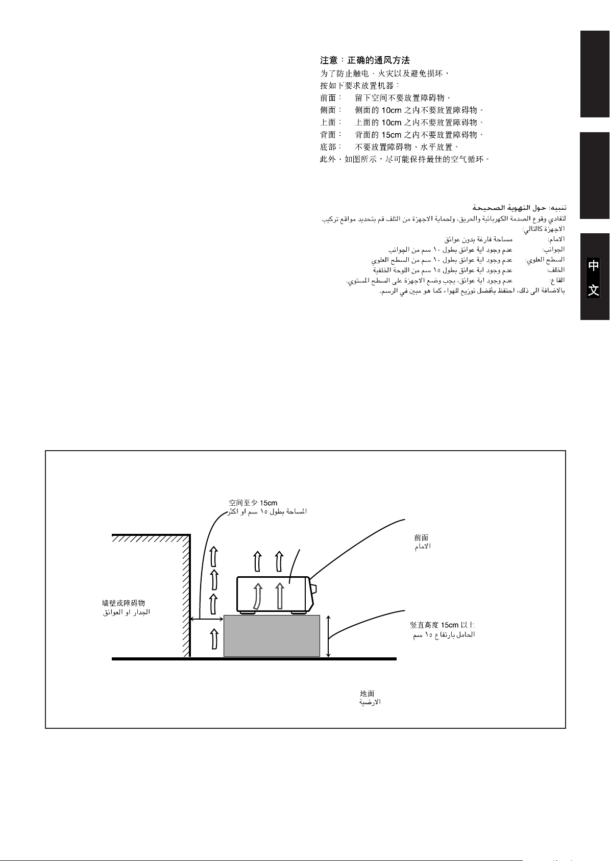
Caution: Proper Ventilation
To avoide risk of electric shock and fire and to protect from damage.
Locate the apparatus as follows:
Front: No obstructions open spacing.
Sides: No obstructions in 10 cm from the sides.
Top: No obstructions in 10 cm from the top.
Back: No obstructions in 15 cm from the back
Bottom: No obstructions, place on the level surface.
In addition, maintain the best possible air circulation as illustrated.
Precaución: Ventilación Adecuada
Para evitar el riesgo de choque eléctrico e incendio y para proteger el
aparato contra daños.
Ubique el aparato de la siguiente manera:
Frente: Espacio abierto sin obstrucciones
Lados: 10 cm sin obstrucciones a los lados
Parte superior: 10 cm sin obstrucciones en la parte superior
Parte trasera: 15 cm sin obstrucciones en la parte trasera
Fondo: Sin obstrucciones, colóquelo sobre una superficie
nivelada
Además, mantenga la mejor circulación de aire posible como se
ilustra.
Precaução: ventilação apropriada
Para prevenir o risco de choque elétrico ou incêndio e para proteger
o aparelho contra danos.
Localize-o da seguinte maneira:
Frente: Espaço aberto, sem obstruções
Lados: Espaço de 10 cm sem obstruções nos lados
Topo: Espaço de 10 cm sem obstruções acima
Atrás: Espaço de 15 cm sem obstruções atrás
Parte inferior: Sem obstruções. Coloque o aparelho em superfície
nivelada.
Mantenha, além disso, a maior circulação de ar possível, como indica
a ilustração.
English
Español
Wall or obstructions
Pared u obstrucciones
Parede ou obstáculo
Spacing 15 cm or more
Espacio de 15 cm o más
Espaço de 15 cm ou mais
RX-889PGD
Floor
Piso
Piso
Front
Frente
Frente
Stand height 15 cm or more
Allura del soporte 15 cm o más
Base com altura de 15 cm ou mais
G-2
Page 4

Table of Contents
Parts Identification ...................................... 2
English
Getting Started ........................................... 3
Before Installation ...................................................................... 3
Checking the Supplied Accessories ........................................... 3
Setting the Voltage Selector Switch ........................................... 3
Connecting the FM and AM Antennas ....................................... 3
Connecting the Speakers ............................................................ 4
Connecting Audio/Video Components....................................... 5
Connecting the Power Cord ....................................................... 8
Putting Batteries in the Remote Control .................................... 8
Basic Operations ......................................... 9
Turning the Power On and Off (Standby) .................................. 9
Selecting the Source to Play....................................................... 9
Adjusting the Volume............................................................... 10
Selecting the Front Speakers .................................................... 10
Muting the Sound ..................................................................... 11
Listening at Low Volume (Loudness) ...................................... 11
Attenuating the Input Signal .................................................... 11
Adjusting the Subwoofer Output Level.................................... 11
Basic Settings ........................................... 12
Recording a Source .................................................................. 12
Adjusting the Front Speaker Output Balance........................... 12
Changing the Source Name...................................................... 12
Setting the Subwoofer Information .......................................... 12
Digital Input (DIGITAL IN) Terminal Setting......................... 13
Selecting the Analog or Digital Input Mode ............................ 13
Showing the Text Information on the Display ......................... 13
Setting the Speakers for the DSP Modes ................................. 14
Setting the AM Tuner Interval Spacing.................................... 16
Using the Sleep Timer.............................................................. 16
Storing the Basic Settings and Adjustments — One Touch
Operation ........................................................................... 16
Using the DSP Modes ................................ 20
Available DSP Modes According to the Speaker Arrangement .. 22
Adjusting the 3D-PHONIC Modes .......................................... 23
Adjusting the DAP Modes ....................................................... 23
Adjusting the Surround Modes ................................................ 24
Activating the DSP Modes....................................................... 27
Using the DVD MULTI Playback Mode .......... 29
Activating the DVD MULTI Playback Mode .......................... 29
Using the On-Screen Menus ........................ 31
Selecting the Source to Play..................................................... 31
Selecting Different Sources for Picture and Sound..................31
Activating the DSP Modes....................................................... 31
Adjusting the Front Speaker Output Balance...........................31
Listening at Low Volume (Loudness) ...................................... 32
Attenuating the Input Signal .................................................... 32
Adjusting the Subwoofer Output Level.................................... 32
Adjusting the DSP Modes ........................................................ 32
Activating the DVD MULTI Playback Mode .......................... 33
Selecting Your Favorite SEA Mode ......................................... 33
Creating Your Own SEA Mode................................................ 33
Setting the Basic Setting Items ................................................ 34
Operating the Tuner.................................................................. 34
Storing the Preset Stations ....................................................... 35
Assigning Names to Preset Stations......................................... 35
COMPU LINK Remote Control System ......... 36
TEXT COMPU LINK Remote Control System .. 37
Showing the Disc Information on the TV Screen .................... 38
Searching for a Disc (Only for the CD player) ........................ 39
Entering the Disc Information.................................................. 40
Operating JVC’s Audio/Video Components ... 42
Receiving Radio Broadcasts ........................ 17
Tuning in Stations Manually .................................................... 17
Using Preset T uning ................................................................. 17
Selecting the FM Reception Mode........................................... 18
Assigning Names to Preset Stations......................................... 18
Using the SEA Modes ................................ 19
Selecting Your Favorite SEA Mode ........................................... 19
Creating Your Own SEA Mode................................................ 19
Operating Other Manufacturers’ Video
Equipment ............................................ 44
Troubleshooting ......................................... 50
Specifications ............................................ 51
1
Page 5
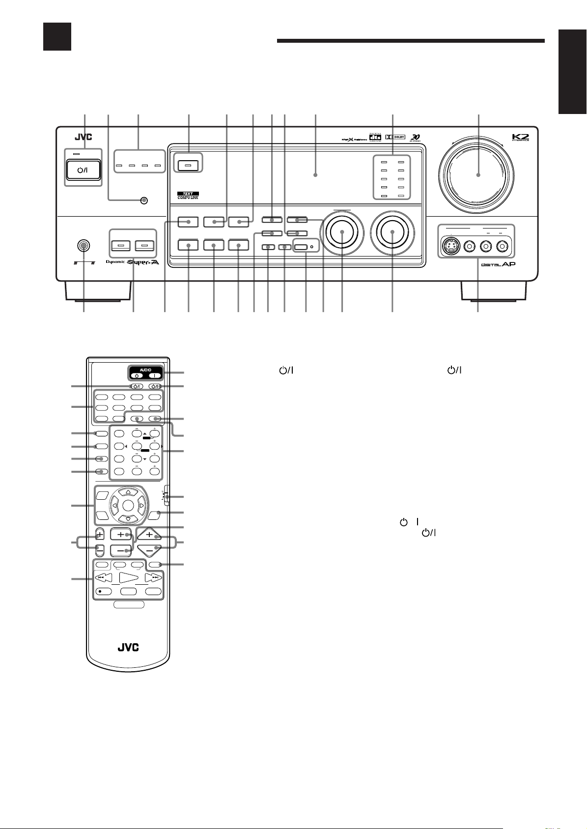
Parts Identification
Become familiar with the buttons and controls on the receiver before use.
Refer to the pages in parentheses for details.
132456789p q
English
1
2
3
4
5
6
7
8
9
STANDBY
STANDBY/ON
PHONES
COMPULINK
Remote
DVD DVD MUILTI CD TAPE/MD
TV/DBS VIDEO PHONO FM/AM
VCR 1 VCR 2
SURROUND CNTR TONE
ON/OFF
SURROUND
MODE
DISC
SOUND
MENU
EXIT
TV/VIDEO
/REW
REC
RX-889P AUDIO/VIDEO CONTROL RECEIVER
DIGITAL SOURCE FORMAT
12
123
TEST REAR-L
456
EFFECT REAR-R
/P
7
SEA MODE
10
RETURN
CHANNEL VOLUMETV VOL
VCR 1
CONTROL
PLAY
TUNINGDOWN UP
RM-SRX889P REMOTE CONTROL
DOLBY
DIGITAL
DTSMPEG
SPEAKERS
TV/CATV/DBS
ANALOG/DIGITAL
SLEEP
CNTR
MENUMENU
ENTERENTER
89
SUBWOOFER
0
FM MODE/MUTING
CATV/DBS
SET
DISPLAY
TAPE
FF/
STOP PAUSE
LINEAR
VCR 1
+10
100+
AUDIO/
TV/VCR
TEXT
MUTING
SURROUND ON/OFF
PCM
BALANCE/SURROUND
DOLBY/DTS/MPEG
DSP MODE
ADJUST
p
q
w
e
r
t
y
u
i
o
INPUT
ANALOG/DIGITAL
SEA MODE
SEA ADJUST SETTING
FM/AM TUNING TUNER PRESET
TUNER/SEA MEMORY
SOUND SELECT
LOUDNESS ONE TOUCH OPERATION
SOURCE NAME
INPUT ATT
FM MODE
MULTI JOG
Front Panel
1 STANDBY/ON button and STANDBY
lamp (9)
2 Remote sensor (8)
3 DIGITAL SOURCE FORMAT lamps (10)
MPEG, DTS, DOLBY DIGITAL, LINEAR
PCM
4 DOLBY/DTS/MPEG SURROUND ON/OFF
button and lamp (27)
5 SEA MODE button (19)
6 INPUT ANALOG/DIGITAL button (13)
7 FM/AM TUNING button (17) *
8 FM MODE button (18)
9 Display (9)
p Source lamps (9)
q MASTER VOLUME control (10)
w PHONES jack (11)
e SPEAKERS 1/2 buttons and lamps (10)
r DSP MODE button (23)
t BALANCE/SURROUND ADJUST button
(11, 12, 23) *
y SEA ADJUST button (19) *
u SETTING button (12 – 15) *
i TUNER/SEA MEMORY button (17 – 19)
o SOUND SELECT/INPUT ATT button
(10, 11)
; LOUDNESS/SOURCE NAME button
(11, 12)
a ONE TOUCH OPERATION button and lamp
(16)
s TUNER PRESET button (18) *
d MULTI JOG control
What this control actually does depends on
which function you are trying to adjust. Before
using this control, select the function by pressing
one of the buttons marked with *.
f SOURCE SELECTOR control (9)
g VIDEO input jacks (7)
DIGITAL
DVD
TV SOUND/DBS PHONO
TAPE/MDVCR 1
VCR 2
VIDEO
SOURCE SELECTOR
CD
FM
AM
1 BIT P-E-M D-D-COMVERTER
MASTER VOLUME
–
VIDEO
S-VIDEO VIDEO AUDIOLR
+
gfdsa;oiuytrew
Remote Control
1 TV/CATV/DBS button (43 – 45)
2 Source selecting buttons (9)
DVD, D VD MULTI, CD, TAPE/MD, TV/DBS,
VIDEO, PHONO, FM/AM, VCR 1, VCR 2
3 SURROUND ON/OFF button (27)
4 SURROUND MODE button (23)
5 DISC button (42)
6 SOUND button (19, 23, 26)
7 On-screen operation buttons (31, 38)
MENU, SET, EXIT, %, fi, @, #
8 TV VOL +/– buttons (43, 44)
9 Operating buttons for audio/video components
(42 – 45)
p AUDIO buttons (9)
,
q VCR 1 button (43, 45)
w SLEEP button (16)
e ANALOG/DIGITAL button (13)
r • 10 keys for selecting preset channel (18)
• 10 keys for adjusting sound (23 – 26, 30)
• 10 keys for operating audio/video components
(42 – 45)
t Remote control mode selector (9, 42, 44)
y TEXT DISPLAY button (38)
u CHANNEL +/– button (43 – 45)
i VOLUME +/– button (10)
o MUTING button (11)
2
Page 6
Getting Started
This section explains how to connect audio/video components and speakers to the receiver, and how to connect the
power supply.
English
Before Installation
Connecting the FM and AM Antennas
General
• Be sure your hands are dry.
• Turn the power off to all components.
• Read the manuals supplied with the components you are going to
connect.
Locations
• Install the receiver in a location that is level and protected from
moisture.
• The temperature around the receiver must be between –5˚ and 35˚
C (23˚ and 95˚ F).
• Make sure there is good ventilation around the receiver. Poor
ventilation could cause overheating and damage the receiver.
Handling the receiver
• Do not insert any metal object into the receiver.
• Do not disassemble the receiver or remove screws, covers, or
cabinet.
• Do not expose the receiver to rain or moisture.
Checking the Supplied Accessories
Check to be sure you have all of the following items, which are
supplied with the receiver.
The number in the parentheses indicates quantity of the pieces
supplied.
• Remote Control (1)
• Batteries (2)
• AM Loop Antenna (1)
• FM Antenna (1)
• AC Plug Adaptor (1) (Except for Hong Kong)
If anything is missing, contact your dealer immediately.
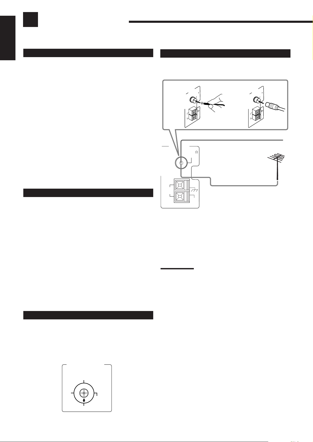
FM Antenna Connections
TENNA
AN
A
5
7
L
M
A
I
F
X
A
O
C
M
A
M
A
T
P
X
O
E
O
L
B
FM Antenna
ANTENNA
AM
LOOP
FM 75
COAXIAL
Extend the supplied FM antenna horizontally.
Outdoor FM Antenna Cable
AM
EXT
A. Using the Supplied FM Antenna
The FM antenna provided can be connected to the FM 75Ω
COAXIAL terminal as temporary measure.
B. Using the Standard Type Connector (Not Supplied)
A standard type connector should be connected to the FM 75Ω
COAXIAL terminal.
Note:
If reception is poor, connect the outdoor antenna.
Before attaching a 75
to an outdoor antenna), disconnect the supplied FM antenna.
Ω
coaxial cable (the kind with a round wire going
TENNA
AN
5
7
L
M
A
I
F
X
A
O
C
M
A
M
A
T
P
X
O
E
O
L
Setting the Voltage Selector Switch
Before connections, always do the following first if necessary.
Set the correct voltage for your area with the voltage selector switch
on the rear panel. Use a screw driver to rotate the switch so the
number the arrow is pointing at is the same as the voltage where you
are plugging in the receiver.
VOLTAGE SELECTOR
220-240V
127V
110V
220V
3
Page 7
+
–+–
RIGHT LEFT
1
2
1
2
FRONT SPEAKERS
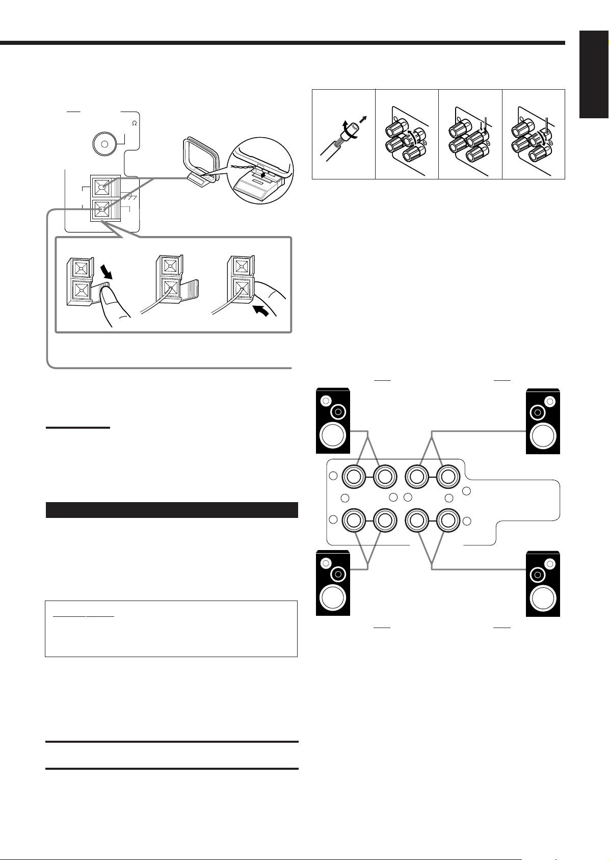
AM Antenna Connections
ANTENNA
FM 75
COAXIAL
Snap the tabs on the loop into the
slots of the base to assemble the
AM loop.
Basic connecting procedure
1
2
1
R
I
G
H
T
3
4
1
R
I
G
H
T
1
R
I
G
H
T
English
AM
LOOP
AM
EXT
1
AM Loop Antenna
2
3
Outdoor single vinyl-covered wire
Turn the loop until you have the best reception.
Notes:
• Make sure the antenna conductors do not touch any other
terminals, connecting cords and power cord. This could cause poor
reception.
• If reception is poor, connect an outdoor single vinyl-covered wire to
the AM EXT terminal. (Keep the AM loop antenna connected.)
1 Cut, twist and remove the insulation at the end of
each speaker signal cable (not supplied).
2 Turn the knob counterclockwise.
3 Insert the speaker signal cable.
4 Turn the knob clockwise.
Connecting the front speakers
You can connect two pairs of front speakers (one pair to the FRONT
SPEAKERS 1 terminals, and another pair to the FRONT
SPEAKERS 2 terminals).
Right speaker
FRONT SPEAKERS 1
Left speaker
Connecting the Speakers
You can connect the following speakers:
• Two pairs of front speakers to produce normal stereo sound.
• One pair of rear speakers to enjoy the surround effect.
• One center speaker to produce more effective surround effect (to
emphasize human voices).
• One subwoofer to enhance the bass.
IMPORTANT:
After connecting the speakers listed above, set the speaker
setting information properly to obtain the best possible DSP
effect. For details, see page 14.
For each speaker (except for a subwoofer), connect the (–) and (+)
terminals on the rear panel to the (–) and (+) terminals marked on
the speakers. For connecting a subwoofer, see page 5.
CAUTION:
Use speakers with the SPEAKER IMPEDANCE indicated by the
speaker terminals.
Right speaker
FRONT SPEAKERS 2
Left speaker
4
Page 8
About the speaker impedance
English
The required speaker impedance of the front speakers does differ
depending on whether both the FRONT SPEAKERS 1 and FRONT
SPEAKERS 2 terminals are used or only one of them is used.
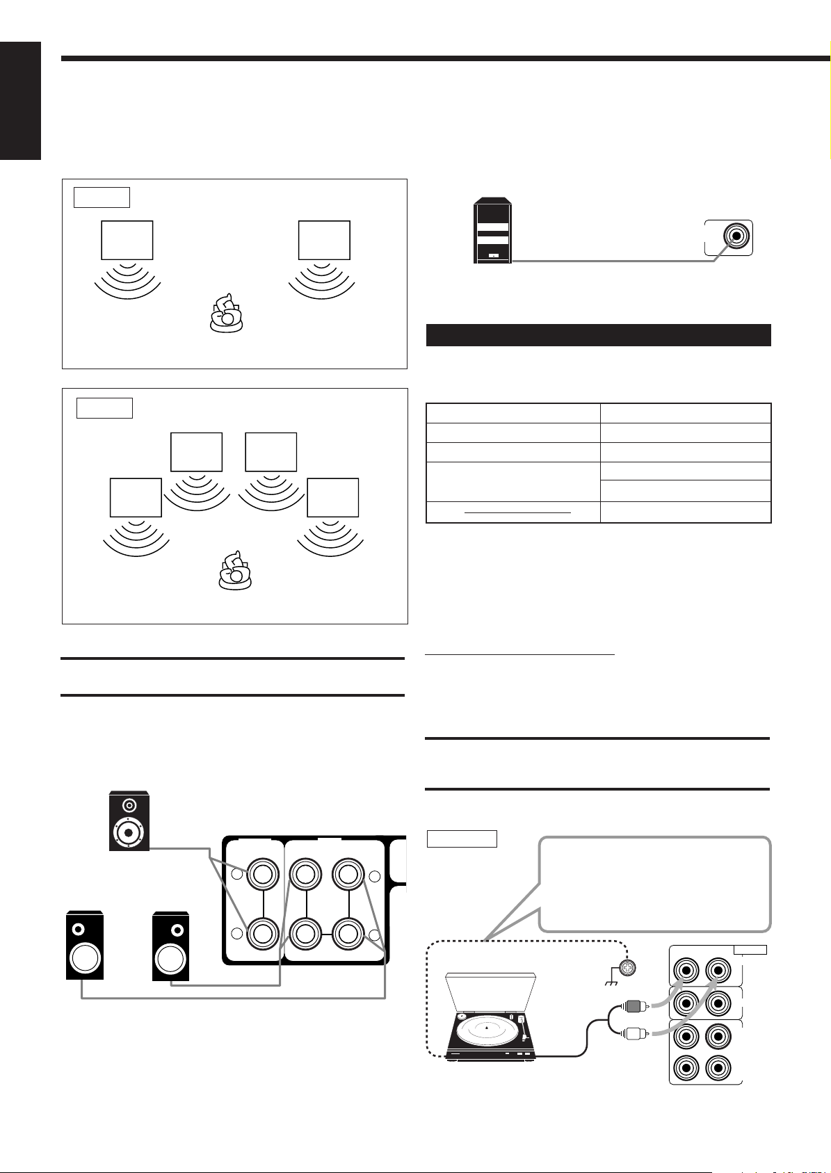
CASE 1 When you connect only one set of front speakers
Connecting the subwoofer speaker
You can enhance the bass by connecting a subwoofer.
Connect the input jack of a powered subwoofer to the
SUBWOOFER OUT jack on the rear panel, using a cable with RCA
pin plugs (not supplied).
Front
speaker 1
Front
speaker 1
Use front speakers with 8 — 16 ohm impedance.
CASE 2 When you connect two sets of front speakers
Front
speaker 1
Front
speaker 2
Front
speaker 1
Front
speaker 2
Use front speakers 16 — 32 ohm impedance.
CAUTION:
Use speakers with the SPEAKER IMPEDANCE indicated by the
speaker terminals.
SUBWOOFER
OUT
Powered subwoofer
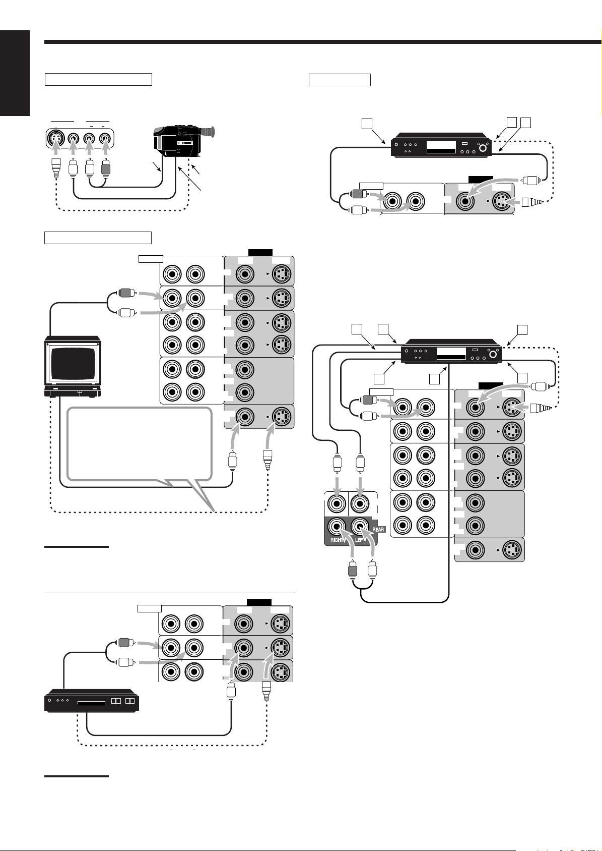
Connecting Audio/Video Components
You can connect the following audio/video components to this
receiver. Refer also to the manuals supplied with your components.
Audio Components Video Components
• Turntable • DVD player*
• CD player* • TV
• Cassette deck • DBS tuner*
or MD recorder* • VCRs
• Video camera
*
You can connect these components using the methods described
in “Analog connections” (below) or in “Digital connections” (see
page 8).
Analog connections
Audio component connections
Use the cables with RCA pin plugs (not supplied).
Connect the white plug to the audio left jack, and the red plug to the
audio right jack.
Connecting the rear and center speakers
Connect rear speakers to the REAR SPEAKERS terminals and a
center speaker to the CENTER SPEAKER terminals.
Center speaker
CENTER
SPEAKER
REAR
SPEAKERS
+
Left rear
speaker
Right rear
speaker
–
RIGHT
LEFT
CAUTION:
If you connect a sound-enhancing device such as a graphic equalizer
between the source components and this receiver, the sound output
through this receiver may be distorted.
Turntable
+
If an earth cable is provided for your
turntable, connect the cable to the
screw marked (H) on the rear panel.
–
Turntable
RIGHT LEFT
To audio output
AUDIO
PHONO
CD
OUT
(REC)
TAPE
/MD
IN
(PLAY)
5
Page 9
Note:
Any turntables incorporating a small-output cartridge such as an MC
(moving-coil type) must be connected to this receiver through a
commercial head amplifier or step-up transformer. Direct connection
may result in insufficient volume.
CD player
RIGHT LEFT
AUDIO
PHONO
CD player
CD
OUT
(REC)
To audio output
TAPE
/MD
IN
(PLAY)
Cassette deck or MD recorder
Cassette deck
IMPORTANT:
This receiver is equipped with both the composite video and S-video
input/output terminals for connecting video components.
You do not have to connect both the composite video and S-video
terminals.
However, remember that the video signals from the composite
video input terminals are output only through the composite
video output terminals, while the ones from the S-video input
terminals are output only through the S-video output terminals.
Therefore, if a recording video component and a playing video
component are connected to the receiver through the different video
terminals, you cannot record the picture from the playing component
on the recording component. In addition, if the TV and a playing video
component are connected to the receiver through the different video
terminals, you cannot view the playback picture from the playing
component on the TV.
To view and record the playback picture from the video
component connected to the VCR 2 jacks, you must connect the
TV and the recording video component through the composite
video terminals.
English
To audio input
RIGHT LEFT
To audio output
AUDIO
PHONO
CD
OUT
(REC)
TAPE
/MD
IN
(PLAY)
MD recorder
To audio input
To audio output
Note:
You can connect either a cassette deck or an MD recorder to the
TAPE/MD jacks. When connecting an MD recorder to the TAPE/MD
jacks, change the source name, which will be shown on the display
when selected as the source, to “MD.” See page 12 for details.
If your audio components have a COMPU LINK-3 or TEXT
COMPU LINK terminal
• See also page 36 for detailed information about the connection and
the COMPU LINK-3 remote control system.
• See also page 37 for detailed information about the connection and
the TEXT COMPU LINK remote control system.
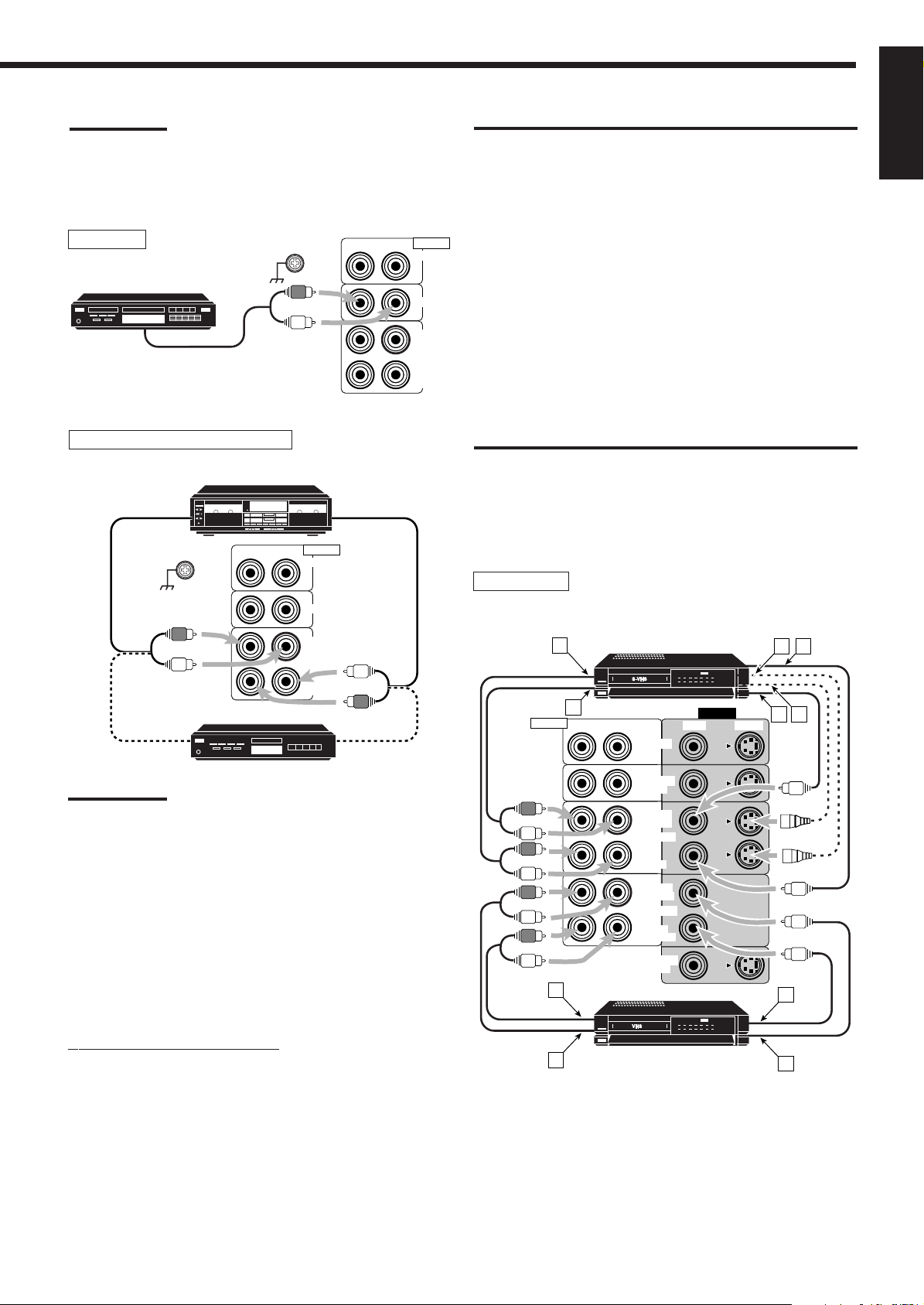
VCR
AUDIO
A
A
S-VHS (or VHS) VCR
B
TV SOUND
(PLAY)
MONITOR
/DBS
OUT
(REC)
VCR 1
IN
(REC)
VCR 2
(PLAY)
OUT
DVD
OUT
IN
DC
VIDEO
VIDEO S-VIDEORIGHT LEFT
F
E
D
Video component connections
Use the cables with RCA pin plugs (not supplied).
Connect the white plug to the audio left jack, the red plug to the
audio right jack, and the yellow plug to the video jack.
If your video components have S-video (Y/C-separation) terminals,
connect them using S-video cables (not supplied). Connecting these
video components through the S-video input/output terminals will
give you better picture playback (or recording) quality.
B
VHS VCR
Å To left/right channel audio output
ı To left/right channel audio input
Ç To S-video output
Î To composite video output
‰ To composite video input
Ï To S-video input
E
6
Page 10
DVD
VIDEO
VIDEO S-VIDEORIGHT LEFT
AUDIO
DVD
A
B
C
Video camera
English
The VIDEO jacks on the front panel is convenient when connecting
and disconnecting the equipment frequently.
VIDEO
S-VIDEO VIDEO AUDIOLR
To audio
output
To S-video output
To composite
video output
DVD player
• When you connect the DVD player with stereo output jacks:
DVD player
TV and/or DBS tuner
VIDEO
VIDEO S-VIDEORIGHT LEFT
To audio
output
TV
Connect the TV to the MONITOR
OUT jack to view the playback
picture from the other connected
video components.
RIGHT
AUDIO
DVD
TV SOUND
/DBS
OUT
(REC)
VCR 1
IN
(PLAY)
OUT
(REC)
VCR 2
IN
(PLAY)
MONITOR
OUT
To composite video input
To S-video input
Notes:
• Use a TV of the PAL- or multi-color system.
• When connecting the TV to the TV SOUND/DBS jacks, DO NOT
connect the TV’s video output to these video input terminals.
Å To front left/right channel audio output (or to audio mixed
output if necessary)
ı To S-video output
Ç To composite video output
• When you connect the DVD player with its analog discrete output
(5.1 CH reproduction) jacks:
DVD player
DVD
ED
DVD
TV SOUND
/DBS
OUT
(REC)
VCR 1
IN
(PLAY)
OUT
(REC)
VCR 2
IN
(PLAY)
MONITOR
OUT
C
VIDEO
VIDEO S-VIDEORIGHT LEFT
F
SUB
WOOFER
A
B
AUDIO
CENTER
DVD
RIGHT
AUDIO
DVD
VIDEO
VIDEO S-VIDEORIGHT LEFT
To audio
output
TV SOUND
/DBS
OUT
(REC)
DBS tuner
IN
DBS
To composite video output
Note:
When connecting the DBS tuner to the TV SOUND/DBS jacks,
change the source name, which will be shown on the display when
selected as the source, to “DBS.” See page 12 for details.
7
To S-video output
(PLAY)
OUT
(REC)
VCR 2
IN
Å To center channel audio output
ı To subwoofer audio output
Ç To S-video output
Î To front left/right channel audio output
‰ To rear left/right channel audio output
Ï To composite video output
Page 11
Digital connections
This receiver is equipped with three DIGITAL IN terminals — one
digital coaxial terminal and two digital optical terminals.
You can connect any component to any one of the digital terminals
using the digital coaxial cable (not supplied) or digital optical cable
(not supplied).
IMPORTANT:
• When connecting the DVD player or the DBS tuner using the digital
terminal, you also need to connect it to the video jack (either
composite video terminal or S-video terminal) on the rear. Without
connecting it to the video jack, you can view no playback picture.
• After connecting the components using the DIGITAL IN terminals,
set the following correctly if necessary.
– Select the digital input mode correctly. For details, see “Selecting
the Analog or Digital Input Mode” on page 13.
– Set the digital input (DIGITAL IN) terminal setting correctly. For
details, see “Digital Input (DIGITAL IN) Terminal Setting” on page
13.
DBS tuner
DBS
DVD player
DVD
Connecting the Power Cord
English
Before plugging the receiver into an AC outlet, make sure that all
connections have been made.
Plug the power cord into an AC outlet.
Keep the power cord away from the connecting cables and the
antenna. The power cord may cause noise or screen interference. We
recommend that you use a coaxial cable to connect the antenna,
since it is well-shielded against interference.
Notes:
• Except for Hong Kong: If the wall outlet does not match the AC
plug, use the supplied AC plug adaptor.
• The preset settings such as preset channel and sound adjustment
may be erased in a few days in the following cases:
– When you unplug the power cord.
– When a power failure occurs.
CAUTIONS:
• Do not plug in before setting the voltage selector switch on the rear
of the unit and all connection procedures are complete.
• Do not touch the power cord with wet hands.
• Do not pull on the power cord to unplug the cord. When unplugging
the cord, always grasp the plug so as not to damage the cord.
CD player
MD recorder
When the component has a digital
coaxial output terminal, connect it to the
DIGITAL 1 (DBS) terminal, using the
digital coaxial cable (not supplied).
DIGITAL IN
PCM / DOLBY DIGITAL
MPEG / DTS
When the component has a digital
optical output terminal, connect it to the
DIGITAL 2 (DVD) or DIGITAL 3 (CD)
DIGITAL 1 (DBS)
terminal, using the digital optical cable
(not supplied).
DIGITAL 2 (DVD)
DIGITAL 3 (CD)
Before connecting a digital
optical cable, unplug the
protective plug.
Notes:
• When shipped from the factory, the DIGITAL IN terminals has been
set for use with the following components.
– DIGITAL 1 (coaxial): For DBS tuner
– DIGITAL 2 (optical): For DVD player
– DIGITAL 3 (optical): For CD player
• When you want to operate the CD player or MD recorder using the
COMPU LINK remote control system, connect the target
component also as described in “Analog connections” (see pages 5
and 6).
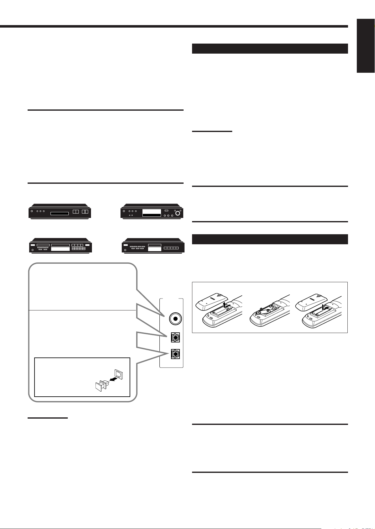
Putting Batteries in the Remote Control
Before using the remote control, put two supplied batteries first.
When using the remote control, aim the remote control directly at
the remote sensor on the receiver.
1
2
3
1. On the back of the remote control, remove the
battery cover.
2. Insert batteries. Make sure to match the polarity:
(+) to (+).
3. Replace the cover.
If the range or effectiveness of the remote control decreases, replace
the batteries. Use two R6P(SUM-3)/AA(15F) type dry-cell batteries.
CAUTION:
Follow these precautions to avoid leaking or cracking cells:
• Place batteries in the remote control so they match the polarity: (+)
to (+).
• Use the correct type of batteries. Batteries that look similar may
differ in voltage.
• Always replace both batteries at the same time.
• Do not expose batteries to heat or flame.
8
Page 12
Basic Operations
The following operations are commonly used when you play any sound source.
IMPORTANT:
English
When using the remote control, check to see if its
remote control mode selector is set to the correct
position:
To operate an audio system, TV, and VCR, set it
to “AUDIO/TV/VCR.”
To operate a CATV converter and DBS tuner,
set it to “CATV/DBS.”
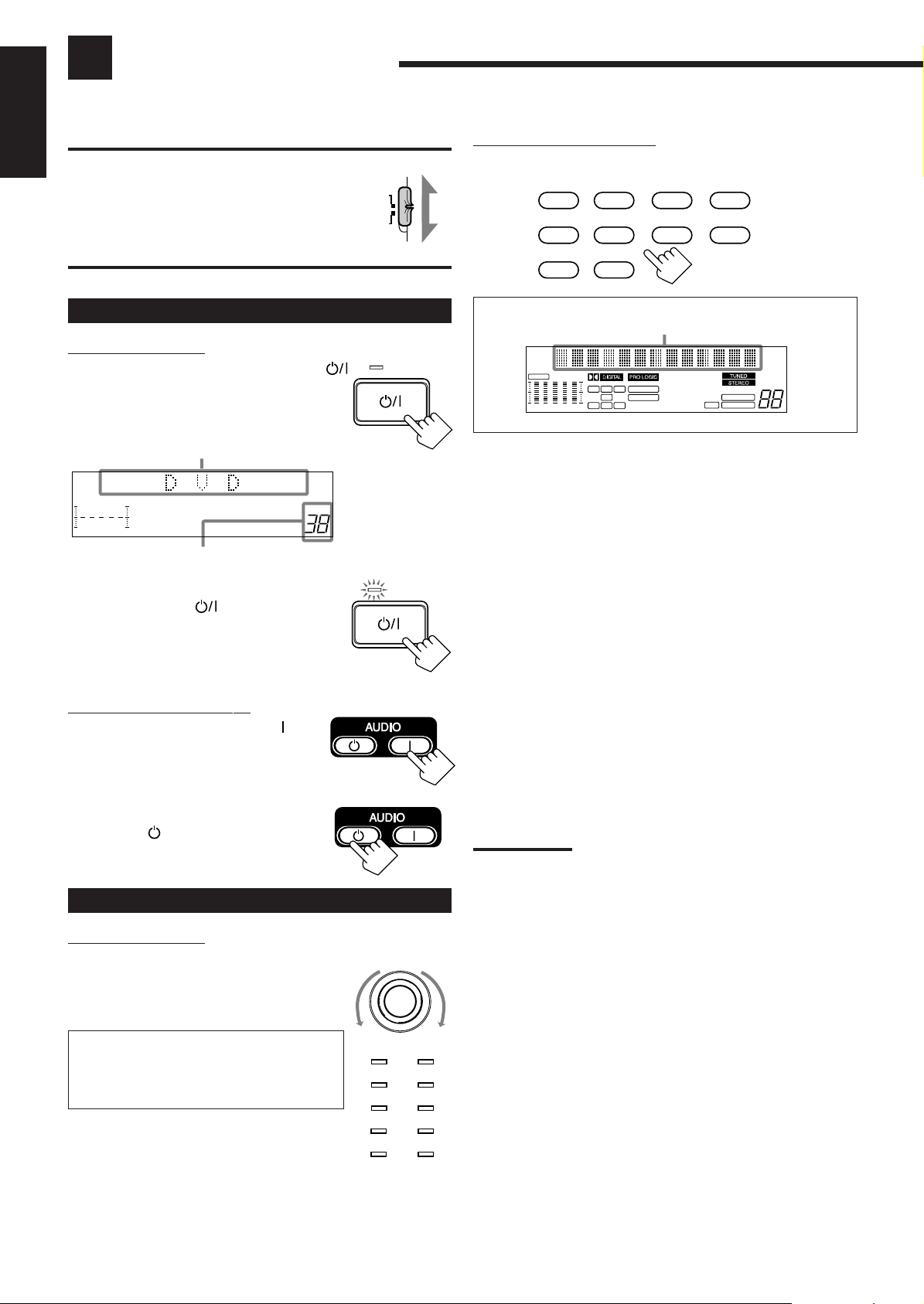
Turning the Power On and Off (Standby)
On the front panel:
To turn on the power, press STANDBY/ON .
The STANDBY lamp goes off. The name of the
current source (or station frequency) appears on
the display.
Current source name appears
100 1k 10k
Current volume level is shown here
To turn off the power (into standby mode),
press STANDBY/ON
again.
The STANDBY lamp lights up. A small amount
of power is consumed in standby mode. To turn
the power off completely, unplug the AC power
cord.
From the remote control:
To turn on the power, press AUDIO .
The STANDBY lamp goes off. The name of
the current source (or station frequency)
appears on the display.
To turn off the power (into standby mode),
press AUDIO
.
The STANDBY lamp lights up.
Selecting the Source to Play
On the front panel:
Turn SOURCE SELECTOR until the source
name you want appears on the display.
• As you turn the selector, the source changes as
follows:
VOLUME
AUDIO/
TV/VCR
CATV/DBS
STANDBY/ON
STANDBY/ON
SOURCE SELECTOR
STANDBY
STANDBY
From the remote control:
Press one of the source selecting buttons.
DVD DVD MUILTI CD TAPE/MD
TV/DBS VIDEO PHONO FM/AM
VCR 1 VCR 2
Selected source name appears
CH–
CNTR
S E A
FR
100 1k 10k
L
C
R
LEE
LS
S
RS
D S P
3D-PHONC
THEATER
LIVE CLUB ACTION
DANCE CLUB
HALL
PA VILION
MUTE AUTO
LOUDNESS
SLEEPATT
VOLUME
DVD Select the DVD player.
DVD MULTI Select the DVD player for viewing the digital video
disc using the analog discrete output mode (5.1CH
reproduction) on the DVD player.
To enjoy the DVD MULTI playback, see page 32.
CD * Select the CD player.
TAPE/MD * Select the cassette deck (or the MD recorder).
TV/DBS • Select TV sounds when the remote control mode
selector is set to “AUDIO/TV/VCR.”
• Select the DBS tuner when the remote control
mode selector is set to “CATV/DBS.”
VIDEO Select video component connected to the VIDEO
jacks.
PHONO * Select the turntable.
FM/AM * Select an FM or AM broadcast.
• Each time you press the button, the band alternates
between FM and AM.
VCR 1 Select the video component connected to the VCR 1
jacks.
VCR 2 Select the video component connected to the VCR 2
jacks.
Notes:
• When connecting an MD recorder (to the TAPE/MD jacks), and a
DBS tuner (to the TV SOUND/DBS jacks), change the source name
shown on the display. For details, see page 12.
• When you press one of the source selecting buttons on the remote
control marked above with an asterisk (*), the receiver
automatically turns on.
CD O PHONO O TAPE (or MD) O FM O
AM O DVD O DVD MULTI O
TV SOUND (or DBS) O VCR 1 O
VCR 2 O VIDEO O (back to the beginning)
The selected source lamp also lights up.
• The DVD lamp lights up both for “DVD” and
“DVD MULTI.”
9
DVD
TV SOUND/DBS PHONO
VCR 2
VIDEO
CD
TAPE/MDVCR 1
FM
AM
Page 13
When playing a digital source through a digital
terminal
• The DIGITAL SOURCE FORMAT lamps on the front panel
indicate what type of the digital signal comes into the receiver.
DIGITAL SOURCE FORMAT
DTS
MPEG
DOLBY
DIGITAL
LINEAR
PCM
MPEG: Lights up when MPEG Multichannel signals
(see page 21) come in.
DTS: Lights up when DTS Digital Surround
signals (see page 21) come in.
DOLBY DIGITAL: Lights up when Dolby Digital signals (see
page 21) come in.
LINEAR PCM: Lights up when Linear PCM signals come in.
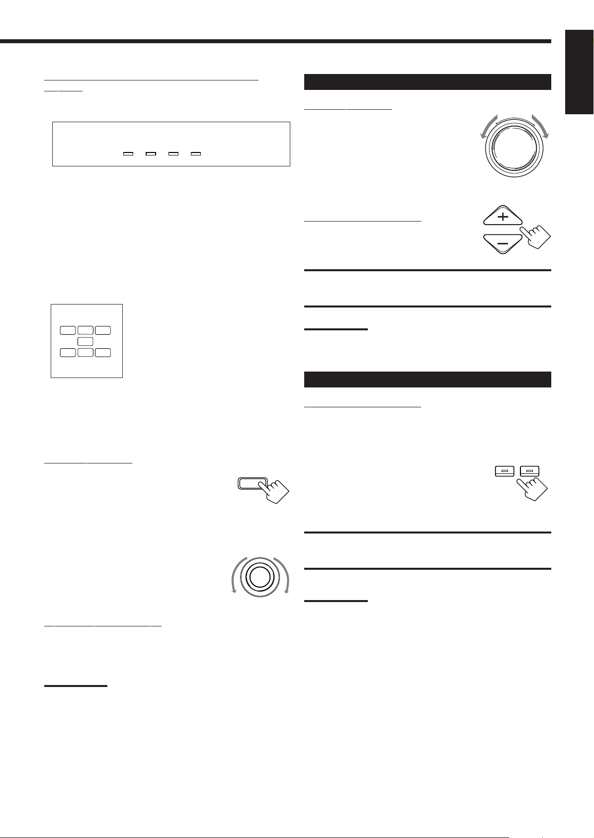
Adjusting the Volume
On the front panel:
To increase the volume, turn MASTER
VOLUME clockwise.
To decrease the volume, turn it
counterclockwise.
• When you turn MASTER VOLUME rapidly,
the volume level also changes rapidly.
• When you turn MASTER VOLUME slowly,
the volume level also chang es slowly.
From the remote control:
To increase the volume, press VOLUME +.
To decrease the volume, press VOLUME –.
MASTER VOLUME
–
VOLUME
English
+
• The signal indicators also light up on the display to indicate the
incoming channel signals. (Only the indicators for the incoming
signals light up.)
L: Left front channel
R: Right front channel
C
L
LS
LFE
S
RS
R
C: Center channel
LS: Left rear channel
RS: Right rear channel
S: Rear channel (monaural)
LFE: Subwoofer channel
Selecting different sources for picture and
sound
You can watch picture from a video component while listening to
sound from another component.
On the front panel:
1. Press SOUND SELECT (INPUT
ATT) briefly while viewing the
picture from a video component
SOUND SELECT
INPUT ATT.
such as the VCR or DVD player,
etc.
“SOUND SELECT” appears on the display.
2. Turn SOURCE SELECTOR to
SOURCE SELECTOR
select the sound (except the TV
sound), while the indication of the
above step is still on the display.
From the remote control:
Press one of the audio source selecting buttons (CD, TAPE/MD,
PHONO, FM/AM), while viewing the picture from a video
component such as the VCR or DVD player, etc.
CAUTION:
Always set the volume to the minimum before star ting any source. If
the volume is set at its high level, the sudden blast of sound energy
can permanently damage your hearing and/or ruin your speakers.
Note:
The volume level can be adjusted within the range of “0” (minimum) to
“90” (maximum).
Selecting the Front Speakers
On the front panel ONLY:
When you have connected two pairs of the front speakers, you can
select which to use.
Press SPEAKERS 1 or SPEAKERS 2 to select
the speaker to use.
• Each time you press the button, the lamp on
the respective button turns on and off. When
the lamp on either button lights up, the
respective speakers are activated.
IMPORT ANT:
You can activate two pairs of the front speakers at the same time only
when no signals are sent to the center and rear speakers. Otherwise,
activating one pair of the speakers deactivates the other.
Note:
If you use any of the DSP modes other than the 3D-PHONIC modes
with both front speakers activated, the speakers connected to the
FRONT SPEAKERS 2 terminals are deactivated.
SPEAKERS
1
2
Notes:
• Once you have selected a video source, pictures of the selected
source are sent to the TV until you select another video source.
• When you select “TV SOUND” as the source, this function does not
work.
10
Page 14
Listening only with headphones
1. Connect a pair of headphones to the PHONES jack on the front
English
panel.
2. Press SPEAKERS 1 and/or 2 so that no lamps on the buttons are
turned on.
Attenuating the Input Signal
When the input level of the playing source is too high, the sounds
will be distorted. If this happens, you need to attenuate the input
signal level to prevent the sound distortion.
CAUTION:
Be sure to turn down the volume before connecting or putting on
headphones, as high volume can damage both the headphones and
your hearing.
Muting the Sound
From the remote control ONLY:
Press MUTING to mute the sound through all
speakers and headphones connected.
MUTING
“MUTING” appears on the display and the
volume turns off (the volume level indicator goes
off).
To restore the sound, press MUTING again so that “OFF” appears
on the display.
• Turning MASTER VOLUME on the front panel or pressing
VOLUME +/– on the remote control also restores the sound.
Listening at Low Volume (Loudness)
Human ears are not sensitive to bass at low volume. To compensate
for this, the loudness function automatically boosts the bass level as
you lower the volume.
On the front panel ONLY:
Press LOUDNESS (SOURCE NAME) briefly
to select the loudness function.
• Each time you press the button, the loudness
function turns on (“LOUDNESS ON”) and off
(“LOUDNESS OFF”).
– Select “LOUDNESS ON” to activate the loudness function.
The LOUDNESS indicator lights up on the display.
– Select “LOUDNESS OFF” to cancel it.
The indicator goes off.
Note:
The loudness function affects the front speaker sounds only.
LOUDNESS
SOURCE NAME
On the front panel ONLY:
Press and hold INPUT ATT (SOUND
SOUND SELECT
SELECT) so that the ATT indicator lights up
on the display.
INPUT ATT
• Each time you press and hold the button, the
Input Attenuator mode turns on (“INPUT ATT
ON”) or off (“INPUT NORMAL”).
Notes:
• This function is available only for the sources connected using the
analog terminals.
• This function takes effect when the DSP mode is in use.
• When selecting “DVD MULTI” as the source, this effect does not
work.
Adjusting the Subwoofer Output Level
You can adjust the subwoofer output level if you have selected
“YES” for the “SUBWOOFER” (see page 12).
Once it has been adjusted, the receiver memorizes the adjustment.
Before you start, remember....
• There is a time limit in doing the following steps. If the setting is
canceled before you finish, start from step 1 again.
On the front panel:
1. Press BALANCE/SURROUND
BALANCE/SURROUND
ADJUST
ADJUST repeatedly until
“SUBWFR LEVEL” appears on
the display.
The display changes to show the current setting.
2. Turn MULTI JOG to adjust the
MULTI JOG
subwoofer output level (–10 dB to
+10 dB).
From the remote control:
SOUND
1. Press SOUND.
The 10 keys are activated for sound adjustments.
11
2. Press SUBWOOFER –/+ to adjust
the subwoofer output level (–10 dB
to +10 dB).
SUBWOOFER
0
FM MODE/MUTING
+10
100+
Page 15
Basic Settings
Some of the following settings are required after connecting and positioning your speakers in your listening room, while
others will make operations easier.
IMPORTANT:
When using the remote control, check to see if its
remote control mode selector is set to the correct
position:
To operate this receiver, set it to “AUDIO/TV/
VCR” (except when selecting the DBS tuner as
the source).
AUDIO/
TV/VCR
CATV/DBS
Recording a Source
You can record any source playing through the receiver to a cassette
deck (or an MD recorder) connected to the TAPE/MD jacks and the
VCRs connected to the VCR 1 and VCR 2 jacks at the same time.
While recording, you can adjust the volume level, without affecting
the sound levels of the recording.
IMPORTANT:
• Before recording a digital source, turn off the DSP mode (see page
20).
• While recording a digital source, do not change the SEA mode
(see page 19) or DSP mode (see page 20); otherwise, recording
will be interrupted.
Changing the Source Name
When you have connected an MD recorder to the TAPE/MD jacks
or the DBS tuner to the TV SOUND/DBS jacks on the rear panel,
change the source name shown on the display when you select the
MD recorder or DBS tuner as the source.
On the front panel ONLY:
1. When changing the source name
SOURCE SELECTOR
from “TAPE” to “MD”:
• Turn SOURCE SELECTOR
until “TAPE” appears.
When changing the source name from “TV
SOUND” to “DBS”:
• Turn SOURCE SELECTOR until “TV
SOUND” appears.
2. Press and hold SOURCE NAME
(LOUDNESS) until “ASSGN.
MD” or “ASSGN. DBS” appears
LOUDNESS
SOURCE NAME
on the display.
English
Note:
The SEA modes and DSP modes cannot affect the recording while
recording an analog source.
Adjusting the Front Speaker Output
Balance
If the sounds you hear from the front right and left speakers are
unequal, you can adjust the speaker output balance.
Before you start, remember....
• There is a time limit in doing the following steps. If the setting is
canceled before you finish, start from step 1 again.
On the front panel ONLY:
1. Press BALANCE/SURROUND
BALANCE/SURROUND
ADJUST
ADJUST repeatedly until “L/R
BALANCE” appears on the
display.
The display changes to show the current setting.
2. Turn MULTI JOG to adjust the
MULTI JOG
balance.
• Turning it clockwise decreases the left
channel output.
• Turning it counterclockwise decreases the
right channel output.
To change the source name to “TAPE” or “TV SOUND,” repeat
the same procedure above — in step 1, select “MD” or “DBS” then
press and hold SOURCE NAME (LOUDNESS).
Note:
Without changing the source name, you can still use the connected
components. However, there may be some inconvenience.
– “TAPE” or “TV SOUND” will appear on the display when you select
the MD recorder or DBS tuner.
– You cannot use the digital input (see page 13) for the MD recorder
and the DBS tuner.
– You cannot use the COMPU LINK remote control system (see page
39) to operate the MD recorder.
Setting the Subwoofer Information
Register whether or not you have connected a subwoofer.
Before you start, remember....
• There is a time limit in doing the following steps. If the setting is
canceled before you finish, start from step 1 again.
On the front panel ONLY:
1. Press SETTING repeatedly until
SETTING
“SUBWOOFER” appears on the
display.
The display changes to show the current setting.
MULTI JOG
2. Turn MULTI JOG to register
whether you have connected a
subwoofer or not.
• As you turn it, the subwoofer setting alternates between
“YES” or “NO.”
YES: Select this when a subwoofer is used.
NO: Select this when no subwoofer is used.
12
Page 16
Digital Input (DIGITAL IN) Terminal
English
Setting
When you use the digital input terminals, you have to register what
components are connected to which terminals (DIGITAL IN 1/2/3).
2. Press INPUT ANALOG/DIGITAL
to change the input mode.
• Each time you press the button, the input
mode alternates between the digital input
and analog input.
INPUT
ANALOG/DIGITAL
Before you start, remember....
• There is a time limit in doing the following steps. If the setting is
canceled before you finish, start from step 1 again.
On the front panel ONLY:
1. Press SETTING repeatedly until
SETTING
“DIGITAL IN” appears on the
display.
The display changes to show the current setting.
DIGITAL 2 terminal setting
DIGITAL 1 terminal setting
DIGITAL 3 terminal setting
MULTI JOG
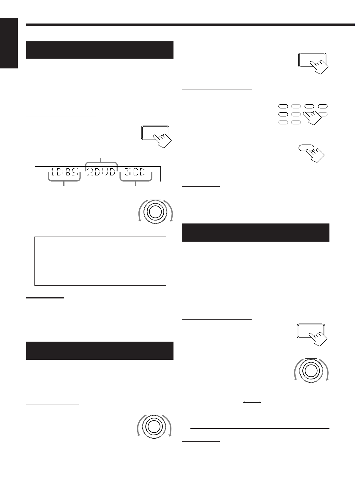
2. Turn MULTI JOG to select the
appropriate digital terminal
setting.
• As you turn it, the display changes to show the following:
1 DBS 2 DVD 3 CD “ 1 MD 2 DVD 3 CD “
1 MD 2 DBS 3 CD “ 1 MD 2 DBS 3 DVD “
1 CD 2 DVD 3 MD “ 1 CD 2 DBS 3 MD “
1 CD 2 DBS 3 DVD “ 1 DVD 2 CD 3 MD “
1 DVD 2 DBS 3 MD “ 1 DVD 2 DBS 3 CD “
1 DBS 2 CD 3 MD “ 1 DBS 2 DVD 3 MD “
(back to the beginning)
Note:
When shipped from the factory, the DIGITAL IN terminals can be used
as the digital input for the following components.
• DIGITAL 1 (coaxial): For DBS tuner
• DIGITAL 2 (optical): For DVD player
• DIGITAL 3 (optical): For CD player
Selecting the Analog or Digital Input
Mode
When you have connected some components such as CD player,
MD recorder, DVD player and the DBS tuner using digital terminals
(see page 8), you need to change the input mode for these
components to the digital input.
On the front panel:
1. Turn SOURCE SELECTOR until
SOURCE SELECTOR
the source (CD, MD, DBS, or
DVD) for which you want to
change the input mode from
analog input to digital input
appears on the display.
13
From the remote control:
1. Press the source selecting button
(CD, T APE/MD, TV/DBS*, or
DVD) f or which y ou want to
change the input mode from
DVD DVD MUILTI CD TAPE/MD
TV/DBS VIDEO PHONO FM/AM
VCR 1 VCR 2
analog input to digital input.
2. Press ANALOG/DIGIT AL to
ANALOG/DIGITAL
change the input mode.
• Each time you press the button, the input
mode alternates between the digital input
and analog input.
Notes:
*
Before pressing TV/DBS, make sure that the remote control mode
selector on the remote control is set to “CATV/DBS.”
• Once you have set the digital input for these components , it is always
used every time you select these components as the source.
Showing the Text Information on the
Display
When you have connected an MD recorder or CD player equipped
with TEXT COMPU LINK remote control system (see page 40),
you can show the text information, such as disc title or track title, on
the display of this receiver. To show it on the display, follow the
procedure below.
Before you start, remember....
• There is a time limit in doing the following steps. If the setting is
canceled before you finish, start from step 1 again.
On the front panel ONLY:
SETTING
1. Press SETTING repeatedly until
“FL DISPLAY” appears on the
display.
The display changes to show the current setting.
MULTI JOG
2. Turn MULTI JOG to select either
the source name or the text
information to be shown on the
display.
• As you turn it, the display changes to show the following:
NORMAL TEXT
NORMAL: Source name appears during play.
TEXT: Text information appears during play.
Notes:
• Though you have selected “TEXT,” the source name such as “CD”
or “MD” appears if a playing disc has no text information.
• Though you have selected “NORMAL,” the setting is changed to
“TEXT” in the following case:
– If the power failure occurs.
– If you unplug the AC power cord.
Page 17
Setting the Speakers for the DSP Modes
To obtain the best possible surround sound of the DSP modes, you
have to register the information about the speakers arrangement after
all connections are completed.
Before you start, remember....
• There is a time limit in doing the following steps. If the setting is
canceled before you finish, start from step 1 again.
Center Delay Time Setting
Register the delay time of the sound from the center speaker,
comparing that of the sound from the front speakers.
If the distance from your listening point to the center speaker is
equal to that to the front speakers, select 0 msec. As the distance to
the center speaker becomes shorter, increase the delay time.
• 1 msec increase (or decrease) in delay time corresponds to 30 cm
13
/16 inches) decrease (or increase) in distance.
(11
• When shipped from the factory, delay time is set to 0 msec.
English
Front, Center, and Rear Speaker Setting
Register the sizes of all the connected speakers.
• When you change your speakers, you need to register the
information about the speakers again.
On the front panel ONLY:
1. Press SETTING repeatedly until
SETTING
“FRONT SPK” (Front Speaker),
“CENTER SPK” (Center
Speaker) or “REAR SPK” (Rear
Speaker) appears on the display.
The display changes to show the current setting.
MULTI JOG
2. Turn MULTI JOG to select the
appropriate item about the speaker
selected in the above step.
• As you turn it, the display changes to show the following:
LARGE SMALL NONE
LARGE: Select this when the speaker size is relatively large.
SMALL: Select this when the speaker size is relatively small.
NONE: Select this when you have not connected a speaker.
(Not selectable for the front speakers)
3. Repeat steps 1 and 2 to select the appropriate
items for the other speakers.
On the front panel ONLY:
1. Press SETTING repeatedly until
SETTING
“CENTER DELAY” appears on
the display.
The display changes to show the current setting.
MULTI JOG
2. Turn MULTI JOG to select the
delay time of the center speaker
output.
• Turn it clockwise to increase the delay time from 0 msec (“C.
DELAY: 0ms”) to 5 msec (“C. DELAY: 5ms”).
• Turn it counterclockwise to decrease the delay time from 5
msec (“C. DELAY: 5ms”) to 0 msec (“C. DELAY: 0ms”).
Note:
Center delay time setting is not valid for the DVD MULTI playback
mode.
Rear Delay Time Setting
Register the delay time of the sound from the rear speakers,
comparing that of the sound from the front speakers.
If the distance from your listening point to the rear speakers is equal
to that to the front speakers, select 0 msec. As the distance to the
rear speakers becomes shorter, increase the delay time.
• 1 msec increase (or decrease) in delay time corresponds to 30 cm
13
/16 inches) decrease (or increase) in distance.
(11
• Rear delay time for Dolby Digital, DTS Digital Surround, and
MPEG Multichannel is to be set to 5 msec.
• When shipped from the factory, delay time is set to 5 msec.
Notes:
• Keep the following comment in mind as reference when adjusting.
– If the size of the cone speaker unit built in your speaker is greater
than 12 cm (4 3/4 inches), select “LARGE,” and if it is smaller than
12 cm (4 3/4 inches), select “SMALL.”
• If you have selected “NO” for the subwoofer setting, you can only
select “LARGE” for the front speaker setting.
• If you have selected “SMALL” for the front speaker setting, you
cannot select “LARGE” for the center and rear speaker settings.
On the front panel ONLY:
SETTING
1. Press SETTING repeatedly until
“REAR DELAY” appears on the
display.
The display changes to show the current setting.
MULTI JOG
2. Turn MULTI JOG to select the
delay time of the rear speaker
output.
• Turn it clockwise to increase the delay time from 0 msec (“R.
DELAY: 0ms”) to 15 msec (“R. DELAY: 15ms”).
• Turn it counterclockwise to decrease the delay time from 15
msec (“R. DELAY: 15ms”) to 0 msec (“R. DELAY: 0ms”).
Note:
Rear delay time setting is not valid for the DVD MULTI playback mode.
14
Page 18

Crossover Frequency Setting
English
Small speaker cannot reproduce the bass sound very well. So, if you
have used a small speaker any for the front, center, or rear channels,
this receiver automatically reallocates the bass elements, originally
assigned to the channel for which you have connected the small
speaker, to another channel (for which you have connected the large
speaker).
To use this function properly, you need to set this crossover
frequency level according to the size of the small speaker connected.
• This function takes effect only when playing back a source using
Dolby Pro Logic, Dolby Digital, DTS Digital Surround, or MPEG
Multichannel. However, if you have selected “LARGE” for all
speakers (see page 14), this function will not take effect.
MULTI JOG
2. Turn MULTI JOG to select the
low frequency effect attenuator
level.
• As you turn it, the display changes to show the following:
0dB 10dB
0dB: Normally select this.
10dB: Select this when the bass sound is distorted.
Note:
Low frequency effect attenuator setting is not valid for the DVD MULTI
playback mode.
On the front panel ONLY:
1. Press SETTING repeatedly until
SETTING
“CROSSOVER FRQ” (Crossover
Frequency) appears on the display.
The display changes to show the current setting.
2. Turn MULTI JOG to select the
MULTI JOG
crossover frequency level
according to the size of the small
speaker connected.
• As you turn it, the display changes to show the following:
80Hz 100Hz 120Hz
• Use the following comments as reference when adjusting.
80Hz: Select this when the cone speaker unit built in the
speaker is about 12 cm (4
100Hz: Select this when the cone speaker unit built in the
speaker is about 10 cm (3
120Hz: Select this when the cone speaker unit built in the
speaker is about 8 cm (3 3/16 inches).
Note:
Crossover frequency setting is not valid for the DVD MULTI playback
mode.
3
/4 inches).
15
/16 inches).
Low Frequency Effect Attenuator Setting
If the bass sound is distorted while playing back a source using
Dolby Digital, DTS Digital Surround, or MPEG Multichannel,
follow the procedure below.
On the front panel ONLY:
1. Press SETTING repeatedly until
SETTING
“LFE ATT” (Low Frequency
Effect Attenuator) appears on the
display.
The display changes to show the current setting.
Dynamic Range Compression Setting
You can compress the dynamic range (difference between maximum
sound and minimum sound) of the reproduced sound. This is useful
when enjoying surround sound at night.
• This function takes effect only when playing back a source using
Dolby Digital.
On the front panel ONLY:
1. Press SETTING repeatedly until
SETTING
“D. RANGE COMP.” (Dynamic
Range Compression) appears on
the display.
The display changes to show the current setting.
MULTI JOG
2. Turn MULTI JOG to select the
appropriate item about the
compression level.
• As you turn it, the display changes to show the following:
OFF MID MAX
OFF: Select this when you want to enjoy surround with its
full dynamic range. (No effect applied)
MID: Select this when you want to reduce the dynamic
range a little. (Factory setting)
MAX: Select this when you want to apply the compression
effect fully. (Useful at night)
Note:
Dynamic Range Compression setting is not valid for the DTS Digital
Surround, MPEG Multichannel, and DVD MULTI playback mode.
15
Page 19

Setting the AM Tuner Interval Spacing
Some countries space AM stations 9 kHz apart, and other countries
use 10 kHz spacing.
On the front panel ONLY:
To select the 10 kHz interval:
Be sure the receiver is turned off, but is plugged into an AC outlet.
Hold down TUNER PRESET and press STANDBY/ON . Now
the 10 kHz interval is selected.
TUNER PRESET
STANDBY
and
STANDBY/ON
To change back to the 9 kHz interval:
Be sure the receiver is turned off, but is plugged into an AC outlet.
Hold down FM MODE and press STANDBY/ON
kHz interval is selected.
FM MODE
. Now the 9
STANDBY
and
STANDBY/ON
Using the Sleep Timer
Using the Sleep Timer, you can fall asleep to music and know the
receiver will turn off by itself rather than play all night.
From the remote control ONLY:
Press SLEEP repeatedly.
The SLEEP indicator lights up on the display,
and the shut-off time changes as follows (in
minutes):
SLEEP
Storing the Basic Settings and
Adjustments — One Touch Operation
JVC’s One Touch Operation function is used to assign and store
different sound settings for each different playing source. By using
this function, you do not have to change the settings every time you
change the source. The stored settings for the newly selected source
are automatically recalled.
The following can be stored for each source:
• Volume level (see page 10)
• Loudness (see page 11)
• Input attenuator mode (see page 11)
• Subwoofer output level (see page 11)
• Balance (see page 12)
• Analog/digital input mode (see page 13)
• SEA modes (see page 19)
• DSP modes
– 3D-PHONIC mode settings (see page 23)
– DAP mode settings (see page 23)
– Surround mode settings (see page 24)
• DVD MULTI playback mode settings (see page 29)
On the front panel ONLY:
To store the sound settings
1. Press ONE TOUCH OPERATION.
ONE TOUCH OPERATION
The ONE TOUCH OPERATION lamp lights
up, then the previously memorized settings
are recalled.
2. Adjust the sound using the functions listed above.
The newly adjusted settings are memorized.
To recall the sound settings
With the ONE TOUCH OPERATION lamp lit, the settings for the
currently selected source are recalled when the source is selected.
English
2010 30 40 50 60 70 80 90
(Canceled)
00
When the shut-off time comes
The receiver turns off automatically.
To check or change the time remaining until the shut-off time
Press SLEEP once.
The remaining time until the shut-off time appears in minutes.
• To change the shut-off time, press SLEEP repeatedly.
To cancel the Sleep Timer
Press SLEEP repeatedly until “SLEEP 00min.” appears on the
display. (The SLEEP indicator goes off.)
• Turning off the power also cancels the Sleep Timer.
To cancel the One Touch Operation function
Press ONE TOUCH OPERATION so that the lamp goes off.
(Even though the One Touch Operation function is canceled, the
recalled sound effects remain active.)
Notes:
• If the source is FM or AM, you can assign a different setting for
each band.
• The DSP modes and DVD MULTI playback mode cannot be used
at the same time.
16
Page 20

Receiving Radio Broadcasts
You can browse through all the stations or use the preset function to go immediately to a particular station.
IMPORT ANT:
English
When using the remote control, check to see if its
remote control mode selector is set to the correct
position:
To operate this receiver, set it to “AUDIO/TV/
VCR” (except when selecting the DBS tuner as
the source).
Tuning in Stations Manually
Check the AM tuner internal spacing (9 kHz or 10 kHz) for your
area. (See page 16.)
On the front panel:
1. Turn SOURCE SELECTOR to
select the band (FM or AM).
The last received station of the selected band
is tuned in.
EON
TA
NEWS
INFO
VOLUME
100 1k 10k
2. Press FM/AM TUNING.
3. Turn MULTI JOG until you find
the frequency you want.
• Turning it clockwise increases the
frequency.
• Turning it counterclockwise decreases the
frequency.
• When you turn MULTI JOG quickly, the
frequency keeps changing until a station is
tuned in.
From the remote control:
1. Press FM/AM to select the band.
• Each time you press the button, the band
alternates between FM and AM.
AUDIO/
TV/VCR
CATV/DBS
SOURCE SELECTOR
FM/AM TUNING
MULTI JOG
FM/AM
Using Preset Tuning
Once a station is assigned to a channel number, the station can be
quickly tuned. You can preset up to 30 FM and 15 AM stations.
To store the preset stations
Before you start, remember...
• There is a time limit in doing the following steps. If the setting is
canceled before you finish, start from step 1 again.
On the front panel ONLY:
1. Tune in the station you want to preset (see
“Tuning in Stations Manually”).
• If you want to store the FM reception mode for this station,
select the FM reception mode you want. See “Selecting the
FM Reception Mode” on page 18.
EON
TA
NEWS
INFO
VOLUME
100 1k 10k
TUNER/SEA MEMORY
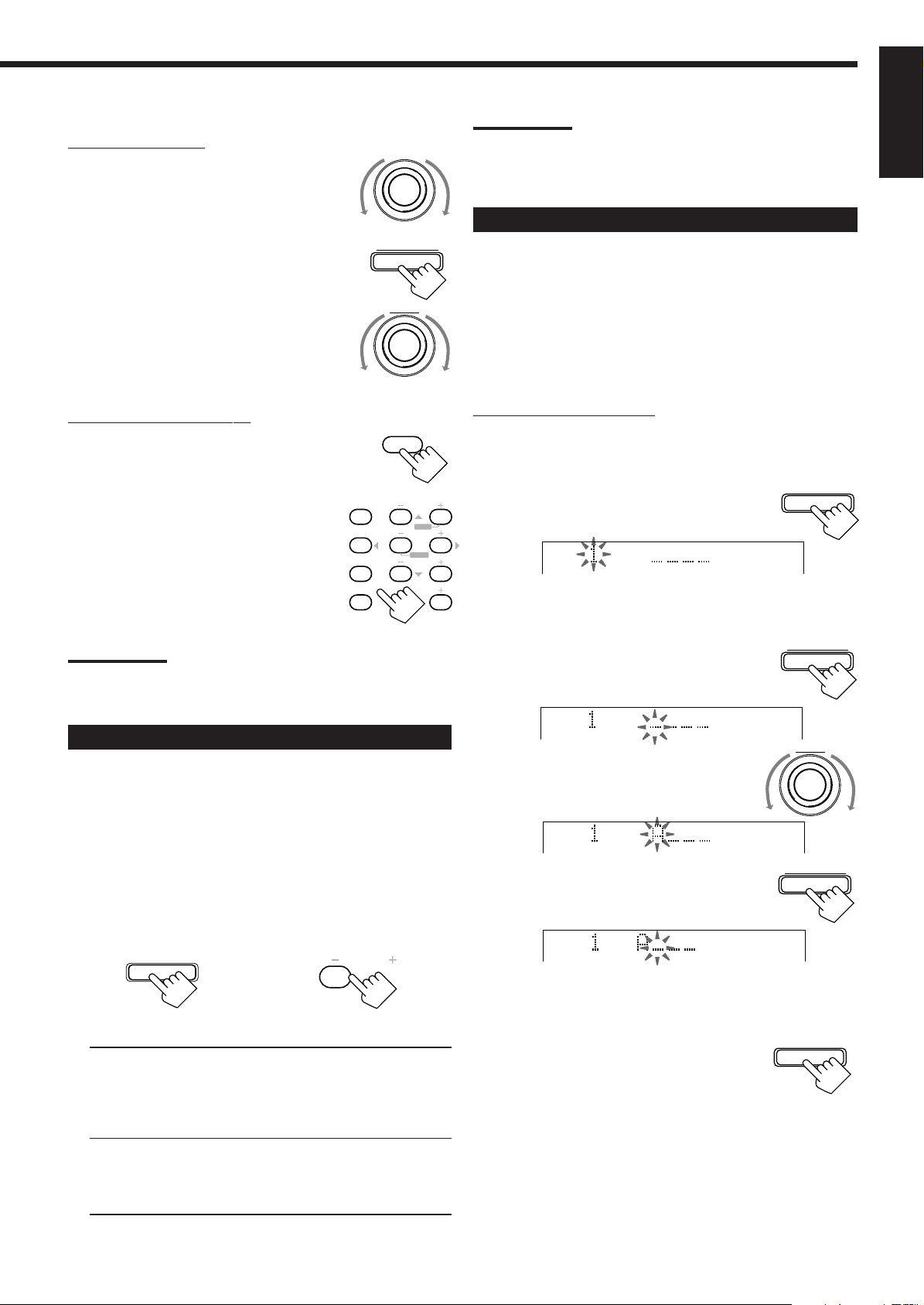
2. Press TUNER/SEA MEMORY .
CH–
100 1k 10k
“CH-” appears and the channel number position starts flashing
on the display for about 10 seconds.
EON
TA
NEWS
INFO
VOLUME
MULTI JOG
3. Turn MULTI JOG to select a
channel number while the channel
number position is flashing.
Note:
You can use the 10 keys on the remote control to select the preset
number. When using the 10 keys, be sure that they are activated
for the tuner, not for the CD and others. (See page 42.)
2. Press TUNING UP or TUNING
DOWN repeatedly until you find
the frequency you want.
• When you hold the button, the frequency
TUNING
DOWN
FF/
UP
/REW
TUNING
keeps changing until a station is tuned in.
Note:
When a station of sufficient signal strength is tuned in, the TUNED
indicator lights up on the display.
When an FM stereo program is received, the STEREO indicator also
lights up.
17
4. Press TUNER/SEA MEMORY
TUNER/SEA MEMORY
again while the selected channel
number is flashing on the display.
The selected channel number stops flashing.
The station is assigned to the selected channel number.
CH–
100 1k 10k
EON
TA
NEWS
INFO
VOLUME
5. Repeat steps 1 to 4 until you store all the stations
you want.
To erase a stored preset station
Storing a new station on a used number erases the previously stored
one.
Page 21
To tune in a preset station
On the front panel:
1. Turn SOURCE SELECTOR to
select the band (FM or AM).
The last received station of the selected band
is tuned in.
2. Press TUNER PRESET.
3. Turn MULTI JOG until you find
the channel you want.
• Turning it clockwise increases the channel
numbers.
• Turning it counterclockwise decreases the
channel numbers.
SOURCE SELECTOR
TUNER PRESET
MULTI JOG
Note:
When using the FM MODE/MUTING button on the remote control, be
sure that the 10 keys are activated for tuner, not for the CD and
others. (See page 42.)
Assigning Names to Preset Stations
You can assign a name of up to four characters to each preset
station. When a preset station is tuned in, its assigned name will
appear on the display.
Before you start, remember...
• There is a time limit in doing the following steps. If the setting is
canceled before you finish, start from step 1 again.
• You can use the following characters: Space, A – Z, and 0 – 9.
English
From the remote control:
1. Press FM/AM.
FM/AM
• Each time you press the button, the band
alternates between FM and AM.
2. Press the 10 keys to select a preset
channel number.
• For channel number 5, press 5.
• For channel number 15, press +10 then 5.
• For channel number 20, press +10 then 10.
• For channel number 30, press +10, +10,
then 10.
CNTR TONE
123
TEST REAR-L
456
EFFECT REAR-R
7
/P 89
SEA MODE
10
RETURN
CNTR
MENU
ENTER
SUBWOOFER
0
FM MODE/MUTING
+10
100+
Note:
When you use the 10 keys on the remote control, be sure that they
are activated for the tuner, not for the CD and others. (See page 42.)
Selecting the FM Reception Mode
When an FM stereo broadcast is hard to
receive or noisy
You can change the FM reception mode while receiving an FM
broadcast.
• You can store the FM reception mode for each preset station.
Press FM MODE on the front panel or FM MODE/MUTING on
the remote control.
• Each time you press the button, the FM reception mode alternates
between “AUTO” and “MONO.”
FM MODE
On the front panel
On the remote control
AUTO: When a program is broadcasted in stereo, you will hear
stereo sound; when in monaural, you will hear
monaural sounds. This mode is also useful to suppress
static noise between stations. The MUTE AUTO
indicator lights up on the display.
MONO: Reception will be improved although you will lose the
stereo effect. In this mode, you will hear noise while
tuning into the stations. The MUTE AUTO indicator
goes off on the display.
SUBWOOFER
0
FM MODE/MUTING
On the front panel ONLY:
1. Tune in a preset station.
See the left.
2. Press TUNER/SEA MEMORY .
TUNER/SEA MEMORY
The preset channel number starts flashing for
about 10 seconds.
CH–
• If you turn MULTI JOG while the preset channel number is
flashing, you can change the preset channel number.
3. Press TUNER PRESET, while the
preset channel number is flashing.
The first character position starts flashing.
CH–
4. Turn MULTI JOG to select the
first character, while the first
character position is flashing.
CH–
5. Press TUNER PRESET, while a
character you want is flashing.
The next character position starts flashing.
CH–
6. Repeat steps 4 and 5 to enter up to four
characters.
7. Press TUNER/SEA MEMORY
TUNER/SEA MEMORY
while the last selected character is
flashing after you have assigned a
name.
To erase the input characters
Insert spaces using the same procedure described above.
TUNER PRESET
MULTI JOG
TUNER PRESET
18
Page 22

Using the SEA Modes
The SEA (Sound Effect Amplifier) modes give you control of the way your music sounds.
IMPORTANT:
English
When using the remote control, check to see if its
remote control mode selector is set to the correct
position:
To operate this receiver, set it to “AUDIO/TV/
VCR” (except when selecting the DBS tuner as
the source).
AUDIO/
TV/VCR
CATV/DBS
Creating Your Own SEA Mode
You can adjust and store your own SEA adjustment into memory
(SEA USERMODE).
Before you start, remember...
• There is a time limit in doing the following steps. If the setting is
canceled before you finish, start from step 1 again.
Selecting Your Favorite SEA Mode
On the front panel:
Press SEA MODE repeatedly until the SEA
mode you want appears on the display.
• Each time you press the button, the SEA mode
changes as follows:
SEA ROCK
SEA MUSICAL SEA MOVIE
SEA USERMODESEA OFF
SEA JAZZ
SEA ROCK: Gives a heavy sound. Both high and low
frequencies are boosted.
SEA MUSICAL: Enhances the mid-frequency range, which
the human voice is mostly made up of.
SEA MOVIE: Adds breadth to sounds so you feel like
you are in a movie theater.
SEA COUNTRY: Enhances the high-frequency range so that
instruments such the violin and banjo are
emphasized.
SEA JAZZ: Gives a feeling of a live atmosphere.
Good for acoustic music.
SEA USERMODE: Your original SEA adjustment (see the
right).
SEA OFF: No SEA mode is applied (see below).
SEA MODE
SEA COUNTRY
On the front panel ONLY:
If you do not want to store your adjustment, but rather want to adjust
the SEA temporarily, skip step 4 below.
1. Press SEA ADJUST repeatedly
SEA ADJUST
until the frequency range (100Hz,
1kHz or 10kHz) you want appears
on the display.
S E A
FR
100 1k 10k
S E A
FR
100 1k 10k
VOLUME
VOLUME
MULTI JOG
2. Turn MULTI JOG to adjust the
SEA level of the selected frequency
range.
• Turning it clockwise increases the level.
• Turning it counterclockwise decreases the level.
This FR means this adjustment can be
S E A
applied to the front speakers only.
FR
Notes:
• The SEA modes cannot be used for recording.
• When the SEA mode is turned on, the SEA indicator lights up on
the display.
• When the SEA mode is used with the DAP mode (see page 23),
sounds may be distorted. If this happens, turn off the DAP mode or
decrease the effect level of the DAP mode.
To cancel the SEA mode
Press SEA MODE repeatedly until “SEA OFF” appears. The SEA
indicator goes off from the display.
From the remote control:
SOUND
1. Press SOUND.
The 10 keys are activated for sound adjustments.
2. Press SEA MODE repeatedly until
the SEA mode you want appears
on the display.
To cancel the SEA mode
Press SEA MODE repeatedly until “SEA OFF” appears in step 2
above. The SEA indicator goes off from the display.
SEA MODE
10
RETURN
100 1k 10k
3. Repeat step 1 and 2 to adjust other frequency
ranges if necessary.
4. Press TUNER/SEA MEMORY .
Your adjustment is stored into the SEA
USERMODE.
To recall your own SEA adjustment
Press SEA MODE repeatedly until “SEA USERMODE” appears.
To erase a stored adjustment
Storing a new adjustment into SEA USERMODE erases the
previously stored one.
TUNER/SEA MEMORY
19
Page 23

Using the DSP Modes
The built-in Surround Processor provides three types of the DSP (Digital Signal Processor) mode — 3D-PHONIC mode,
DAP (Digital Acoustic Processor) mode and Surround mode.
English
3D-PHONIC modes
The 3D-PHONIC mode gives you such a nearly surround effect as it
is reproduced through the Dolby Surround decoder, which is widely
used to reproduce sounds with a feeling of movement like those
experienced in movie theaters. The 3D-PHONIC mode is the result
of research on sound localization technology carried out at JVC for
many years. This mode can be used when the front speakers are
connected to this receiver (without respect to the rear/center
speaker connection).
• You can select either 3D ACTION or 3D THEATER to your
preference when playing an analog or Linear PCM (digital)
source.
• You can select either 3D DIGITAL or 3D THEATER to your
preference when playing a Dolby Digital, DTS Digital Surround,
or MPEG Multichannel source.
3D ACTION: Best for action and war movies — where the
action is fast and explosive.
3D DIGITAL: Reproduces multi-sound source encoded with
Dolby Digital, DTS Digital Surround, or MPEG
Multichannel.
3D THEA TER: Reproduces the sound field of a large theater. This
mode can be selected when only front speakers are
connected to this receiver and “REAR SPK” and
“CENTER SPK” is set to “NONE” (see page 14).
Note on the subwoofer sound when using the 3D-PHONIC
modes
Sound will or will not come out of the subwoofer according to the
selected 3D-PHONIC mode.
• With “3D ACTION” selected: No sound comes out.
• With “3D DIGITAL” selected: Sound comes out if the subwoofer
channel signals come into this receiver ( LFE of the signal
indicators lights up — see page 10) while playing a multi-sound
source encoded with Dolby Digital, DTS Digital Surround, or
MPEG Multichannel.
• With “3D THEA TER” selected:
– If “FRONT SPK” is set to “SMALL,” sound comes out while
playing any source.
– If “FRONT SPK” is set to “LARGE,” sound comes out only if
the subwoofer channel signals come into this receiver ( LFE of
the signal indicators lights up — see page 10) while playing a
multi-sound source encoded with Dolby Digital, DTS Digital
Surround, or MPEG Multichannel.
DAP modes
The sound heard in a concert hall or club consists of direct sound
and indirect sound — early reflections and reflections from behind.
Direct sounds reach the listener directly without any reflection. On
the other hand, indirect sounds are delayed by the distances of the
ceiling and walls. These direct sounds and indirect sounds are the
most important elements of the acoustic surround effects. The DAP
mode can create these important elements, and gives you a real
“being there” feeling. This mode can be used when the front
speakers are connected to this receiver (without respect to the
rear/center speaker connection).
You can select one of the following to your preference.
LIVE CLUB: Gives the feeling of a live music club with a low
ceiling.
DANCE CLUB:Gives a throbbing bass beat.
HALL: Gives clear vocal and the feeling of a concert hall.
PAVILION: Gives the spacious feeling of a pavilion with a high
ceiling.
Reflections from
Early reflections
Direct sounds
behind
20
Page 24
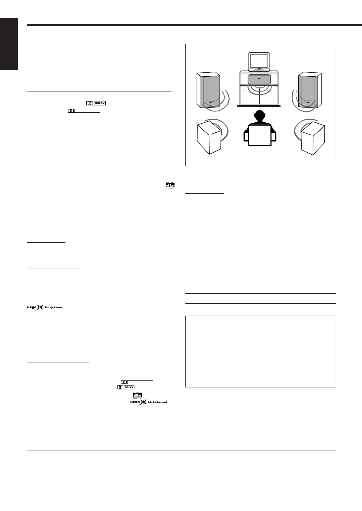
Surround modes
English
With this receiver, you can use four types of the Surround mode.
Following modes cannot be used when only the front speakers
are connected to this receiver (without the rear speakers or
center speaker).
Dolby Surround (Dolby Digital and Dolby Pro Logic)
*
Used to reproduce the soundtracks of software encoded with Dolby
Digital (bearing the mark
(bearing the mark
DOLBY SURROUND
DIGITAL
) or with Dolby Surround
).
Dolby Digital and Dolby Pro Logic can be selected automatically
according to software played back and the speaker arrangement you
have done.
• To enjoy the software encoded with Dolby Digital, you must
connect the source component using the digital terminal on the
rear of this receiver. (See page 8.)
DTS Digital Surround
**
DTS Digital Surround is a discrete 5.1 channel digital audio format
available on CD, LD, and DVD software.
T o reproduce the soundtracks of video softw are bearing the mark
the receiver can provide you with DTS Digital Surround decoder.
DTS Digital Surround is automatically selected according to
software played back and the speaker arrangement you have done.
• To enjoy the software encoded with DTS Digital Surround, you
must connect the source component using the digital terminal on
the rear of this receiver. (See page 8.)
Note:
A CD encoded with DTS Digital Surround cannot be played back
through this receiver.
MPEG Multichannel
MPEG Multichannel is another discrete 5.1 channel digital audio
format available on DVD software, and uses encoding method called
MPEG2-Audio. (MPEG stands for “Motion Picture Expert Group”
and has been originally developed for compressing video signals. )
To reproduce the soundtracks of video software bearing the mark
, the receiver can provide you with MPEG
Multichannel decoder.
MPEG Multichannel is automatically selected according to software
played back and the speaker arrangement you have done.
• To enjoy the software encoded with MPEG Multichannel, you
must connect the source component using the digital terminal on
the rear of this receiver. (See page 8.)
JVC Theater Surround
In order to reproduce a more realistic sound field in your listening
room while playing soundtracks of software encoded;
– with Dolby Surround (bearing the mark
– with Dolby Digital (bearing the mark
– with DTS Digital Surround (bearing the mark
– with MPEG Multichannel (bearing the mark
DOLBY SURROUND
DIGITAL
),
),
),
),
you can use JVC Theater Surround.
• When playing a source encoded with Dolby Digital, with DTS
Digital Surround, or MPEG Multichannel, “DIG THEATER” is
selected automatically.
• When playing a source encoded with Dolby Surround,
“THEATER” is selected automatically.
,
Notes:
• The DSP modes have no effect on monaural sources.
• The DSP modes cannot be used for recording an analog source.
• When you select “DVD MULTI” as the source to play, you cannot
select or adjust the DSP modes.
• The
PRO LOGIC
decoder built in this receiver is activated.
• The Ÿ
• The Dolby Pro Logic decoder is used not only for the analog
DIGITAL
Dolby Digital come into the receiver.
sources but also for the sources encoded with Dolby Digital, DTS
Digital Surround, or MPEG Multichannel in the following cases:
– When only front channel signals are encoded.
– When front channel and monaural rear channel signals are
encoded.
indicator lights up when the Dolby Pro Logic
indicator lights up when the signals encoded with
IMPORT ANT:
Before recording a digital source, turn off the DSP mode.
DVD MULTI Playback Mode
This receiver provides the DVD MULTI playback mode for
reproducing the analog discrete 5.1 channel output mode of the
DVD player or other equipment.
You can adjust the DVD MULTI playback mode while playing
back a video software such as a DVD using the analog discrete
5.1 channel output mode.
• For the DVD MULTI playback mode connection, see page 7.
• For details on the DVD MULTI playback mode, see page 29.
*
Manufactured under license from Dolby Laboratories. “Dolby,” “Pro
Logic,” and the double-D symbol are trademarks of Dolby
Laboratories. Confidential Unpublished Works. ©1992–1998 Dolby
Laboratories, Inc. All rights reserved.
21
**
Manufactured under license from Digital Theater Systems, Inc. US
Pat. No. 5,451,942 and other world-wide patents issues and
pending. “DTS” and “DTS Digital Surround” are trademarks of
Digital Theater Systems, Inc. ©1996 Digital Theater Systems, Inc.
All rights reserved.
Page 25

Available DSP Modes According to the Speaker Arrangement
Available DSP modes will vary depending on how many speakers are used with this receiver.
Make sure that you have set the speaker information correctly (see page 14).
English
Front
speaker
Front
speaker
Front
speaker
Rear
speaker
Speaker arrangements
TV
TV
Center speaker
TV
Front
speaker
Front
speaker
Front
speaker
Rear
speaker
Available DSP modes
Each time you press DSP MODE on the front panel or SURROUND MODE on
the remote control, the DSP modes change as follows:
• 3D THEATER
• LIVE CLUB
• DANCE CLUB
• HALL
• PAVILION
• 3D ACTION (or 3D DIGITAL)
• DSP OFF (DSP mode is canceled)
Each time you press DSP MODE on the front panel or SURROUND MODE on
the remote control, the DSP modes change as follows:
By pressing DSP MODE:
• THEATER (or DIG THEATER)
• LIVE CLUB
• DANCE CLUB
• HALL
• PAVILION
• 3D ACTION (or 3D DIGITAL)
• DSP OFF (DSP mode is canceled)
To activate the Surround
mode, press DOLBY/DTS/
MPEG SURROUND ON/OFF
button so that the lamp on the
button lights up.
By pressing SURROUND MODE:
• DOLBY/DTS/MPEG SURROUND
(DOLBY PRO LOGIC, DOLBY
DIGITAL, DTS SURROUND, or
MPEG SURROUND)
• THEATER (or DIG THEATER)
• LIVE CLUB
• DANCE CLUB
• HALL
• PAVILION
• 3D ACTION (or 3D DIGITAL)
• DSP OFF (DSP mode is canceled)
To activate the Surround
mode, you can also use the
SURROUND ON/OFF button.
Front
speaker
Rear
speaker
TV
Center speaker
Front
speaker
Rear
speaker
Note on the center speaker sound when using the DAP modes:
Sounds come out of the center speaker only if the following take place at
the same time;
• If “CENTER SPK” is set to “LARGE” or “SMALL.”
• If the center channel signals come into this receiver ( C of the signal
indicators lights up — see page 10) while playing a multi-sound source
encoded with Dolby Digital, DTS Digital Surround, or MPEG
Multichannel.
In this case, you cannot adjust the center speaker output level.
22
Page 26

IMPORTANT:
English
When using the remote control, check to see if its
remote control mode selector is set to the correct
position:
To operate this receiver, set it to “AUDIO/TV/
VCR” (except when selecting the DBS tuner as
the source).
Adjusting the 3D-PHONIC Modes
AUDIO/
TV/VCR
CATV/DBS
3. Press EFFECT to select an effect
level you want.
• Each time you press the button, the effect
level changes as follows:
DSP EFFECT 1 DSP EFFECT 2 DSP EFFECT 3
DSP EFFECT 4DSP EFFECT 5
As the number increases, the selected 3D-PHONIC mode
becomes stronger.
EFFECT
7
/P
Once you have adjusted the 3D-PHONIC modes, the adjustment is
memorized for each 3D-PHONIC mode.
Before you start, remember...
• Make sure that you have set the speaker information correctly
(see page 14).
• There is a time limit in doing the following steps. If the setting is
canceled before you finish, start from step 1 again.
On the front panel:
DSP MODE
1. Press DSP MODE repeatedly until
“3D ACTION (or 3D DIGITAL)”
or “3D THEATER” appears on
the display.
The 3D-PHONIC, DSP, PRO LOGIC and selected 3D-PHONIC
mode indicators also light up on the display.
BALANCE/SURROUND
2. Adjust the effect level.
ADJUST
1) Press BALANCE/SURROUND
ADJUST repeatedly until “DSP
EFFECT” appears on the display.
The display changes to show the current
setting.
MULTI JOG
2) Turn MULTI JOG to select the effect
level.
• As you turn it, the effect level changes
as follows:
DSP EFFECT 1 DSP EFFECT 2 DSP EFFECT 3
DSP EFFECT 4DSP EFFECT 5
As the number increases, the selected 3D-PHONIC mode
becomes stronger.
From the remote control:
1. Press SURROUND MODE
repeatedly until “3D ACTION (or
SURROUND
MODE
3D DIGITAL)” or “3D
THEATER” appears on the
display.
The 3D-PHONIC, DSP, PRO LOGIC and selected 3D-PHONIC
mode indicators also light up on the display.
SOUND
2. Press SOUND.
The 10 keys are activated for sound adjustments.
Adjusting the DAP Modes
Once you have adjusted the DAP modes, the adjustment is
memorized for each DAP mode.
Before you start, remember...
• Make sure that you have set the speaker information correctly
(see page 14).
• There is a time limit in doing the following steps. If the setting is
canceled before you finish, start from step 1 again.
• You cannot adjust the rear speak er output level when you have set
“REAR SPK” to “NONE.” See page 14.
• When the DAP mode is used with the SEA mode (see page 19),
sounds may be distorted. If this happens, turn off the SEA mode.
On the front panel:
1. Press DSP MODE repeatedly until
DSP MODE
the DAP mode — LIVE CLUB,
DANCE CLUB, HALL, or
PAVILION — appears on the
display.
The DSP and the selected DAP mode indicators also light up on
the display.
• When you have set “REAR SPK” to “NONE,” the 3DPHONIC indicator also lights up.
2. Adjust the speaker output levels.
1) Press BALANCE/SURROUND
ADJUST repeatedly until one of the
indications appears on the display.
“REAR L LEVEL”:
To adjust the left rear speaker level.
“REAR R LEVEL”:
To adjust the right rear speaker level.
2) Turn MULTI JOG to adjust the
selected speaker output level (from –10
dB to +10 dB).
3) Repeat 1) and 2) to adjust the other
speaker output level.
BALANCE/SURROUND
ADJUST
MULTI JOG
23
Page 27

3. Adjust the effect level.
1) Press BALANCE/SURROUND
ADJUST repeatedly until “DSP
EFFECT” appears on the display.
The display changes to show the current
setting.
2) Turn MULTI JOG to select the effect
level.
• As you turn it, the effect level changes
as follows:
BALANCE/SURROUND
ADJUST
MULTI JOG
DSP EFFECT 1 DSP EFFECT 2 DSP EFFECT 3
DSP EFFECT 4DSP EFFECT 5
As the number increases, the selected DAP mode becomes
stronger.
From the remote control:
1. Press SURROUND MODE
repeatedly until the DAP mode —
SURROUND
MODE
LIVE CLUB, DANCE CLUB,
HALL, or PAVILION — appears
on the display.
The DSP and the selected DAP mode indicators also light up on
the display.
SOUND
2. Press SOUND.
The 10 keys are activated for sound adjustments.
REAR•L
3. Adjust the speaker output levels.
• To adjust the left rear speaker level, press
REAR•L –/+ (from –10 dB to +10 dB).
• To adjust the right rear speaker level, press
REAR•R –/+ (from –10 dB to +10 dB).
4. Press EFFECT to select an effect
level you want.
• Each time you press the button, the effect
level changes as follows:
DSP EFFECT 1 DSP EFFECT 2 DSP EFFECT 3
DSP EFFECT 4DSP EFFECT 5
56
ENTERENTER
REAR•R
89
EFFECT
7
/P
Adjusting the Surround Modes
Once you have adjusted the Surround modes, the adjustment is
memorized for each Surround mode.
Dolby/DTS/MPEG Surround adjustments
Before you start, remember...
• Make sure that you have set the speaker information correctly
(see page 14).
• There is a time limit in doing the following steps. If the setting is
canceled before you finish, start from step 1 again.
• You cannot adjust the rear speaker output levels when you have set
“REAR SPK” to “NONE.” See page 14.
• You cannot adjust the center speaker output level and center tone
when you have set “CENTER SPK” to “NONE.” See page 14.
From the remote control:
1. Press SURROUND MODE
repeatedly until the mode — PRO
SURROUND
MODE
LOGIC, DOLBY DIGITAL, DTS
SURROUND, or MPEG
SURROUND — appears on the
display.
• When “PRO LOGIC” is selected, the PRO LOGIC indicator
lights up on the display.
Note:
You can also press SURROUND ON/OFF to activate an
appropriate Surround mode — PRO LOGIC, DOLBY DIGITAL,
DTS SURROUND, MPEG SURROUND. Each time you press the
button, the Surround mode turns on and off alternately.
SOUND
2. Press SOUND.
The 10 keys are activated for sound adjustments.
3. Press TEST to check the speaker
output balance.
“TEST TONE L” starts flashing on the
display, and a test tone comes out of the
speakers in the following order:
TEST TONE L
(Left front speaker)
TEST TONE LS
(Left rear speaker)
TEST TONE C
(Center speaker)
TEST TONE RS
(Right rear speaker)
TEST
4
TEST TONE R
(Right front speaker)
English
As the number increases, the selected DAP mode becomes
stronger.
24
Page 28
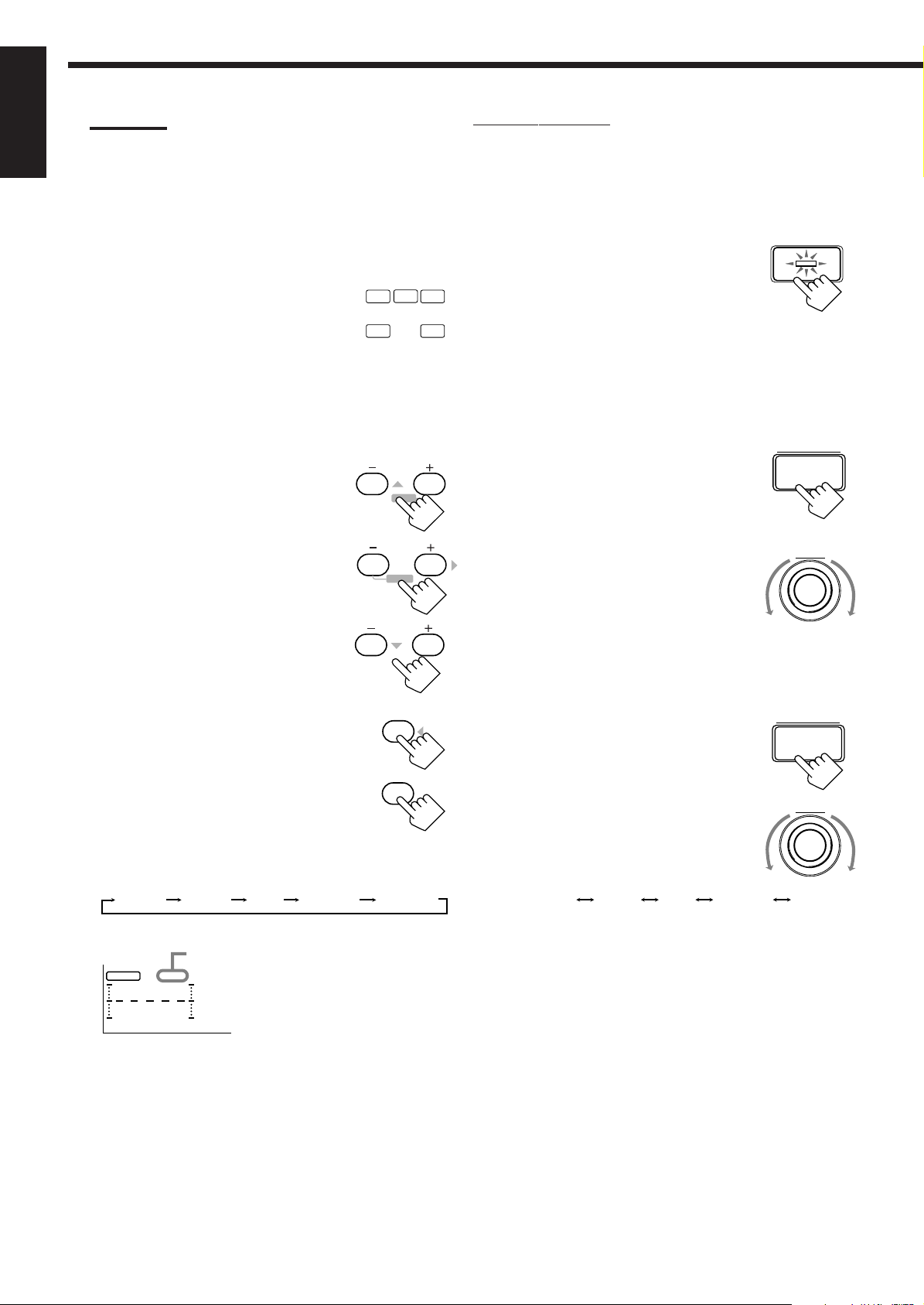
Notes:
SHARP 1 SHARP 2FLATSOFT 2 SOFT 1
English
• You can adjust the speaker output levels without outputting the
test tone.
• No test tone comes out of the center speaker when “CENTER
SPK” is set to “NONE” (see page 14).
• No test tone comes out of the rear speakers when “REAR SPK”
is set to “NONE” (see page 14).
• If the TV is turned on and the proper video input is selected on
the TV, the test tone screen will appear on the TV.
• The signal indicators also light on the display while the test tone
comes out of the speakers.
L: Lights when the test tone comes out of
the left front speaker.
C: Lights when the test tone comes out of
the center speaker.
R: Lights when the test tone comes out of the right front
speaker.
RS: Lights when the test tone comes out of the right rear
speaker.
LS: Lights when the test tone comes out of the left rear
speaker.
4. Adjust the speaker output levels.
• To adjust the center speaker level, press
CNTR –/+ (from –10 dB to +10 dB).
• To adjust the left rear speaker level, press
REAR•L –/+ (from –10 dB to +10 dB).
• To adjust the right rear speaker level, press
REAR•R –/+ (from –10 dB to +10 dB).
C
L
LS
23
56
REAR•R
R
RS
CNTR
MENUMENU
REAR•L
ENTER
89
On the front panel:
You can also use the buttons on the front panel to adjust the
Surround modes. However, no test tone is available when using the
buttons on the front panel. So, make adjustments while listening to
the sound of the source played back.
1. Press DOLBY/DTS/MPEG
DOLBY/DTS/MPEG
SURROUND ON/OFF
SURROUND ON/OFF to activate
an appropriate Surround mode —
PRO LOGIC, DOLBY DIGITAL,
DTS SURROUND, or MPEG
SURROUND.
• Each time you press the button, the Surround mode turns on
and off alternately.
• When “PRO LOGIC” is selected, the PRO LOGIC indicator
lights up on the display.
2. Adjust the speaker output levels.
1) Press BALANCE/SURROUND
ADJUST repeatedly until one of the
indications appears on the display.
“CENTER LEVEL”:
To adjust the center speaker level.
“REAR L LEVEL”:
To adjust the left rear speaker level.
“REAR R LEVEL”:
To adjust the right rear speaker level.
2) Turn MULTI JOG to adjust the
selected speaker output level (from –10
dB to +10 dB).
3) Repeat 1) and 2) to adjust the other
speaker output levels.
BALANCE/SURROUND
ADJUST
MULTI JOG
5. Press TEST again to stop the test tone.
6. Press CNTR TONE to select the
TEST
CNTR TONE
center tone level you want.
The center tone adjustment affects the midfrequency range, which the human voice is
mostly made up of.
• Each time you press the button, the display changes to show
the following:
SOFT 2
SOFT 1
Adjusted levels are also shown on the equalizer display.
This CNTR means this adjustment can
S E A
CNTR
be applied to the center speaker only.
(Example: When “FLAT” is selected.)
100 1k 10k
To make the dialogue clearer, select “SHARP 1” (little) or
“SHARP 2” (much).
To make the dialogue softer, select “SOFT 1” (little) or “SOFT
2” (much).
When “FLAT” is selected, no adjustment is applied.
SHARP 1 SHARP 2FLAT
3. Adjust the center tone.
4
1) Press BALANCE/SURROUND
BALANCE/SURROUND
ADJUST
ADJUST repeatedly until “CENTER
TONE” appears on the display.
The display changes to show the current
1
setting.
2) Turn MULTI JOG to select the center
MULTI JOG
tone level you want.
• As you turn it, the display changes to
show the following:
25
Page 29

JVC Theater Surround adjustments
Before you start, remember...
• Make sure that you have set the speaker information correctly
(see page 14).
• There is a time limit in doing the following steps. If the setting is
canceled before you finish, start from step 1 again.
• You cannot adjust the rear speaker output levels when you have set
“REAR SPK” to “NONE.” See page 14.
• You cannot adjust the center speaker output level and center tone
when you have set “CENTER SPK” to “NONE.” See page 14.
From the remote control:
1. Press SURROUND MODE
repeatedly until “THEATER” or
SURROUND
MODE
“DIG THEATER” appears on the
display.
• When “THEATER” is selected, the PRO LOGIC, DSP, and
THEATER indicators also light up on the display.
• When “DIG THEATER” is selected, the DSP and THEATER
indicators also light up on the display.
2. Press SOUND.
SOUND
The 10 keys are activated for sound adjustments.
3. Press TEST to check the speaker
LS
TEST
4
C
L
R
RS
output balance.
“TEST TONE L” starts flashing on the
display, and a test tone comes out of the
speakers in the following order:
TEST TONE L
(Left front speaker)
TEST TONE C
(Center speaker)
TEST TONE LS
(Left rear speaker)
Notes:
• You can adjust the speaker output levels without outputting the
test tone.
• No test tone comes out of the center speaker when “CENTER
SPK” is set to “NONE” (see page 14).
• No test tone comes out of the rear speakers when “REAR SPK”
is set to “NONE” (see page 14).
• If the TV is turned on and the proper video input is selected on
the TV, the test tone screen will appear on the TV.
• The signal indicators also light on the display while the test tone
comes out of the speakers.
L: Lights when the test tone comes out of
the left front speaker.
C: Lights when the test tone comes out of
the center speaker.
R: Lights when the test tone comes out of the right front
speaker.
RS: Lights when the test tone comes out of the right rear
speaker.
LS: Lights when the test tone comes out of the left rear
speaker.
TEST TONE R
(Right front speaker)
TEST TONE RS
(Right rear speaker)
4. Adjust the speaker output levels.
• To adjust the center speaker level, press
CNTR
23
CNTR –/+ (from –10 dB to +10 dB).
• To adjust the left rear speaker level, press
REAR•L –/+ (from –10 dB to +10 dB).
• To adjust the right rear speaker level, press
REAR•R –/+ (from –10 dB to +10 dB).
REAR•L
56
ENTERENTER
REAR•R
89
5. Press TEST again to stop the test tone.
6. Press CNTR TONE to select the
TEST
CNTR TONE
center tone level you want.
The center tone adjustment affects the midfrequency range, which the human voice is
mostly made up of.
• Each time you press the button, the display changes to show
the following:
SOFT 2
SOFT 1
SHARP 1 SHARP 2FLAT
Adjusted levels are also shown on the equalizer display.
This CNTR means this adjustment can
be applied to the center speaker only.
S E A
CNTR
(Example: When “FLAT” is selected.)
100 1k 10k
To make the dialogue clearer, select “SHARP 1” (little) or
“SHARP 2” (much).
To make the dialogue softer, select “SOFT 1” (little) or “SOFT
2” (much).
When “FLAT” is selected, no adjustment is applied.
7. Press EFFECT to select an effect
EFFECT
level you want.
• Each time you press the button, the effect
level changes as follows:
DSP EFFECT 1 DSP EFFECT 2 DSP EFFECT 3
DSP EFFECT 4DSP EFFECT 5
As the number increases, JVC Theater Surround becomes
stronger.
MENUMENU
4
1
7
/P
English
26
Page 30

On the front panel:
You can also use the buttons on the front panel to adjust the
English
Surround modes. However, no test tone is available when using the
buttons on the front panel. So, make adjustments while listening to
the sound of the source played back.
1. Press DSP MODE repeatedly until
“THEATER” or “DIG
THEATER” appears on the
display.
• When “THEATER” is selected, the PRO LOGIC, DSP, and
THEATER indicators light up on the display.
• When “DIG THEATER” is selected, the DSP and THEATER
indicators light up on the display.
2. Adjust the speaker output levels.
BALANCE/SURROUND
1) Press BALANCE/SURROUND
ADJUST repeatedly until one of the
indications appears on the display.
“CENTER LEVEL”:
To adjust the center speaker level.
“REAR L LEVEL”:
To adjust the left rear speaker level.
“REAR R LEVEL”:
To adjust the right rear speaker level.
2) Turn MULTI JOG to adjust the
selected speaker output level (from –10
dB to +10 dB).
3) Repeat 1) and 2) to adjust the other
speaker output levels.
3. Adjust the center tone.
1) Press BALANCE/SURROUND
ADJUST repeatedly until “CENTER
TONE” appears on the display.
The display changes to show the current
setting.
2) Turn MULTI JOG to select the center
tone level you want.
• As you turn it, the display changes to
show the following:
4. Adjust the effect level.
1) Press BALANCE/SURROUND
ADJUST repeatedly until “DSP
EFFECT” appears on the display.
The display changes to show the current
setting.
2) Turn MULTI JOG to select the effect
level.
• As you turn it, the effect level changes
as follows:
DSP EFFECT 1 DSP EFFECT 2 DSP EFFECT 3
BALANCE/SURROUND
SHARP 1 SHARP 2FLATSOFT 2 SOFT 1
BALANCE/SURROUND
DSP MODE
ADJUST
MULTI JOG
ADJUST
MULTI JOG
ADJUST
MULTI JOG
Activating the DSP Modes
You can use only one DSP mode at a time. When a DSP mode is
activated, another DSP mode is canceled if in use.
For Dolby Pro Logic, Dolby Digital, DTS Digital
Surround, and MPEG Multichannel
On the front panel:
1. Press DOLBY/DTS/MPEG
SURROUND ON/OFF so that the
DOLBY/DTS/MPEG
SURROUND ON/OFF
lamp on the button lights up.
• Each time you press the button, the Dolby/
DTS/MPEG Surround turns on and off
alternately.
2. Select and play a sound source.
• To enjoy Dolby Pro Logic, play back a software encoded with
Dolby Surround and labeled with
DOLBY SURROUND
mark.
• To enjoy Dolby Digital, play back a software encoded with
Dolby Digital and labeled with
DIGITAL
mark.
• To enjoy DTS Digital Surround, play back a software encoded
with DTS Digital Surround and labeled with mark.
• To enjoy MPEG Multichannel, play back a software encoded
with MPEG Multichannel and labeled with
mark.
To cancel the Dolby/DTS/MPEG Surround mode
Press DOLBY/DTS/MPEG SURROUND ON/
OFF again so that the lamp on the button goes
off. (“SURROUND OFF” appears on the
display.)
From the remote control:
1. Press SURROUND ON/OFF so
that the lamp on the DOLBY/DTS/
DOLBY/DTS/MPEG
SURROUND ON/OFF
SURROUND
ON/OFF
MPEG SURROUND ON/OFF
button on the front panel lights up.
• Each time you press the button, the Dolby/DTS/MPEG
Surround turns on and off alternately.
• You can also turn on Dolby/DTS/MPEG Surround by pressing
SURROUND MODE. (See page 22 for more details.)
2. Select and play a sound source.
• To enjoy Dolby Pro Logic, play back a software encoded with
Dolby Surround and labeled with
• To enjoy Dolby Digital, play back a software encoded with
Dolby Digital and labeled with
• To enjoy DTS Digital Surround, play back a software encoded
with DTS Digital Surround and labeled with mark.
• To enjoy MPEG Multichannel, play back a software encoded
with MPEG Multichannel and labeled with
mark.
DOLBY SURROUND
DIGITAL
mark.
mark.
DSP EFFECT 4DSP EFFECT 5
As the number increases, JVC Theater Surround becomes
stronger.
27
To cancel the Dolby/DTS/MPEG Surround mode
Press SURROUND ON/OFF again.
(“SURROUND OFF” appears on the display.)
SURROUND
ON/OFF
Page 31

For the other DSP modes
On the front panel:
1. Press DSP MODE repeatedly until
DSP MODE
the mode you want appears on the
display.
• Each time you press the button, the DSP
modes change. (See page 22 for more
details.)
2. Select and play a sound source.
• To enjoy 3D-PHONIC and JVC Theater Surround, play back a
software:
– encoded with Dolby Surround and labeled with
DOLBY SURROUND
– encoded with Dolby Digital and labeled with
DIGITAL
– encoded with DTS Digital Surround and labeled with
mark.
– encoded with MPEG Multichannel and labeled with
mark.
mark.
mark.
––––––––––––––– MEMO –––––––––––––––
Use this column to write down your DSP mode adjustments for
your future reference.
English
To cancel the DSP mode
Press DSP MODE repeatedly until “DSP OFF”
DSP MODE
appears on the display.
From the remote control:
1. Press SURROUND MODE
repeatedly until the DSP mode you
SURROUND
MODE
want appears on the display.
• Each time you press the button, the DSP
modes change. You can also turn on Dolby/
DTS/MPEG Surround. (See page 22 for
more details.)
2. Select and play a sound source.
• To enjoy 3D-PHONIC and JVC Theater Surround, play back a
software:
– encoded with Dolby Surround and labeled with
DOLBY SURROUND
– encoded with Dolby Digital and labeled with
DIGITAL
– encoded with DTS Digital Surround and labeled with
mark.
– encoded with MPEG Multichannel and labeled with
mark.
mark.
mark.
To cancel the DSP mode
Press SURROUND MODE repeatedly until
“DSP OFF” appears on the display.
SURROUND
MODE
28
Page 32
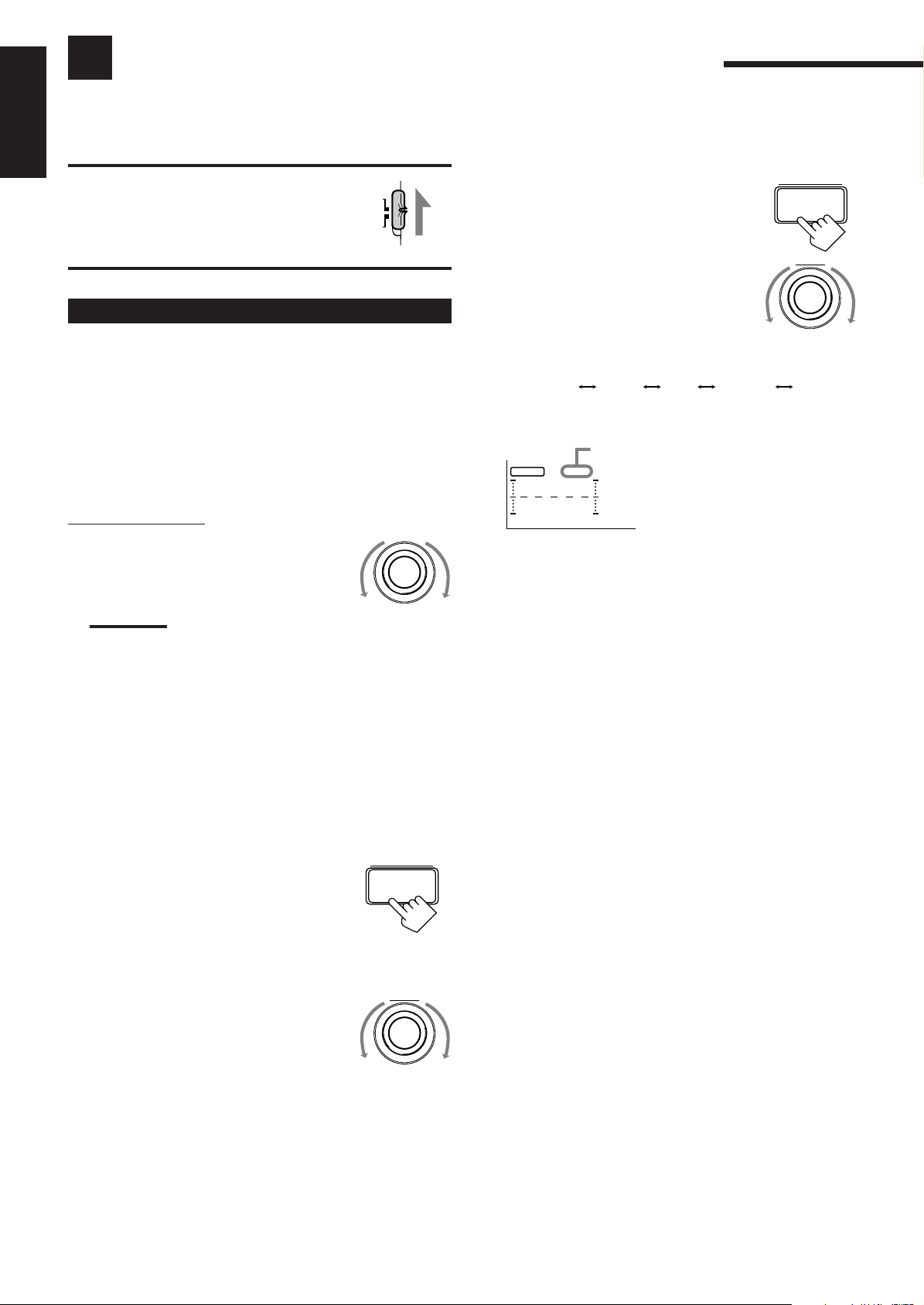
Using the DVD MULTI Playback Mode
SHARP 1 SHARP 2FLATSOFT 2 SOFT 1
This receiver provides the DVD MULTI playback mode for reproducing the analog discrete output mode of the DVD
player. Before playing back a DVD, refer also to the manual supplied with the DVD player.
English
IMPORTANT:
When using the remote control, check to see if its
remote control mode selector is set to the correct
position:
To operate this receiver, set it to “AUDIO/TV/
VCR” (except when selecting the DBS tuner as
the source).
Activating the DVD MULTI Playback Mode
You can adjust the DVD MULTI playback mode while playing back
a DVD using the analog discrete output mode on the DVD player.
Once you made adjustments, the receiver memorizes the
adjustments until you change them. You also need to set the DVD
player to the analog discrete output mode.
Before you start, remember...
• There is a time limit in doing the following steps. If the setting is
canceled before you finish, start from step 1 again.
AUDIO/
TV/VCR
CATV/DBS
4. Adjust the center tone.
1) Press BALANCE/SURROUND
ADJUST repeatedly until “CENTER
TONE” appears on the display.
The display changes to show the current
setting.
2) Turn MULTI JOG to select the center
tone level you want.
The center tone adjustment affects the
mid-frequency range, which the human
voice is mostly made up of.
• As you turn it, the display changes to
show the following:
Adjusted levels are also shown on the equalizer display.
S E A
CNTR
This CNTR means this adjustment can
be applied to the center speaker only.
(Example: When “FLAT” is selected.)
BALANCE/SURROUND
ADJUST
MULTI JOG
On the front panel:
1. Turn SOURCE SELECTOR until
SOURCE SELECTOR
“DVD MULTI” appears on the
display.
Note:
When you select “DVD MULTI” as the source to play, the DSP
mode is canceled temporarily, and the DOLBY/DTS/MPEG
SURROUND ON/OFF and DSP MODE buttons do not work.
2. Select the analog discrete output mode on the
DVD player, and start playing a DVD.
• Refer to the manual supplied with the DVD player.
If you need to make any adjustment, go to the following
steps.
3. Adjust the speaker output levels.
1) Press BALANCE/SURROUND
ADJUST repeatedly until one of the
indications appears on the display.
“CENTER LEVEL”:
To adjust the center speaker level.
“REAR L LEVEL”:
To adjust the left rear speaker level.
“REAR R LEVEL”:
To adjust the right rear speaker level.
2) Turn MULTI JOG to adjust the
selected speaker output level (from –10
dB to +10 dB).
3) Repeat 1) and 2) to adjust the other
speaker output levels.
BALANCE/SURROUND
ADJUST
MULTI JOG
100 1k 10k
To make the dialogue clearer, select “SHARP 1” (little) or
“SHARP 2” (much).
To make the dialogue softer, select “SOFT 1” (little) or “SOFT
2” (much).
When “FLAT” is selected, no adjustment is applied.
29
Page 33

From the remote control:
1. Press DVD MULTI so that “DVD
DVD MUILTI
MULTI” appears on the display.
Note:
When you select “DVD MULTI” as the source to play, the DSP
mode is canceled temporarily, and the SURROUND ON/OFF and
SURROUND MODE buttons do not work.
2. Select the analog discrete output mode on the
DVD player, and start playing a DVD.
• Refer to the manual supplied with the DVD player.
If you need to make any adjustment, go to the following
steps.
SOUND
3. Press SOUND.
The 10 keys are activated for adjusting the sound.
––––––––––––––– MEMO –––––––––––––––
Use this column to write down your DVD MULTI playback
mode adjustments for your future reference.
English
4. Adjust the speaker output levels.
• To adjust the center speaker level, press
CNTR –/+ (from –10 dB to +10 dB).
• To adjust the left rear speaker level, press
REAR•L –/+ (from –10 dB to +10 dB).
• To adjust the right rear speaker level, press
REAR•R –/+ (from –10 dB to +10 dB).
5. Press CNTR TONE to select the
center tone level you want.
• Each time you press the button, the display
changes to show the following:
SOFT 2
SOFT 1
SHARP 1 SHARP 2FLAT
CNTR
23
MENUMENU
REAR•L
56
ENTERENTER
REAR•R
89
CNTR TONE
1
30
Page 34
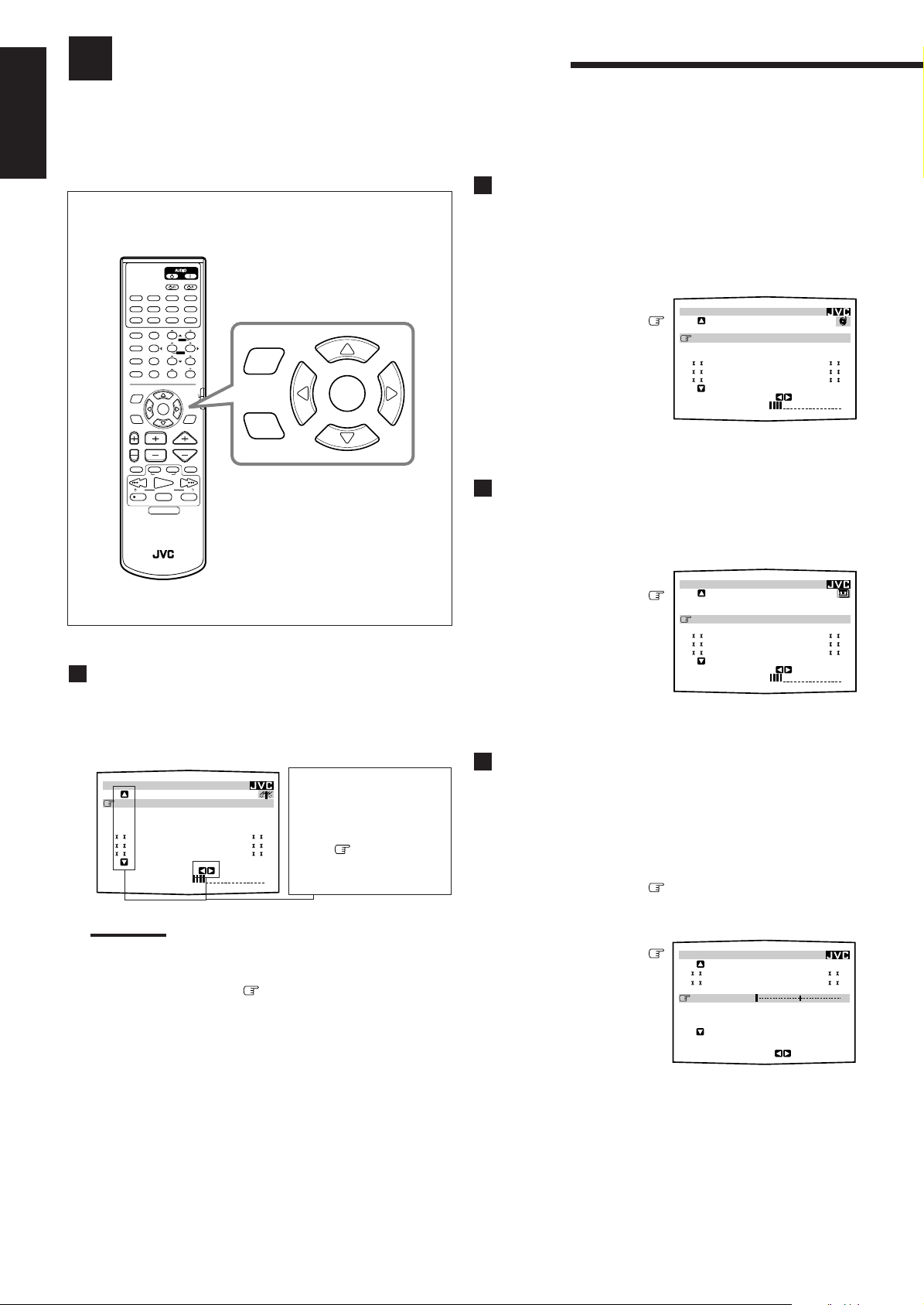
Using the On-Screen Menus
MAIN MENU
SOURCE :PHONO
VISUAL :VCR1
MODE :OFF
SOUND CONTROL
TUNER CONTROL
SETTING
VOLUME : 20
:OPERATE
SOUND CONTROL
SURROUND LEVEL
SEA
BAL.:R-21
LOUDNESS : OFF
INPUT ATT : NORMAL
SUBWFR LEVEL: 0
dB
NEXT PAGE
:OPERATE
You can use the Menus on the TV screen to control the receiver.
To use this function, you need to connect the TV to the MONITOR OUT jack on the rear panel (see page 7), and set the
TV’s input mode to the proper position to which the receiver is connected.
English
• When the TV’s input mode is incorrect; for example, a different video input or TV tuner mode is selected, you
cannot show the Menus on the TV screen.
Selecting Different Sources for Picture and
On-Screen Operation buttons (on the remote control)
TV/CATV/DBS
ANALOG/DIGITAL
CNTR
123
MENUMENU
TEST REAR-L
456
ENTERENTER
EFFECT REAR-R
7
/P
89
SUBWOOFER
SEA MODE
10
0
RETURN
FM MODE/MUTING
SET
CHANNEL VOLUMETV VOL
VCR 1
TAPE
CONTROL
FF/
PLAY
PTY SEARCH
STOP PAUSE
DISPLAY MODE
CATV/DBS
VCR 1
SLEEP
+10
100+
AUDIO/
TV/VCR
TEXT
DISPLAY
MUTING
MENU
SET
EXIT
DVD DVD MUILTI CD TAPE/MD
TV/DBS VIDEO PHONO FM/AM
VCR 1 VCR 2
SURROUND CNTR TONE
ON/OFF
SURROUND
MODE
DISC
SOUND
MENU
EXIT
TV/VIDEO
/REW
PTY PTY
REC
RM-SRX889P REMOTE CONTROL
Selecting the Source to Play (Also see page 9)
1. Press MENU.
The MAIN MENU appears on the TV.
• Pressing one of the % / fi / @ / # buttons also displays the
MAIN MENU.
MAIN MENU
SOURCE :ch 1 FM 87.50
VISUAL :VCR1
MODE :OFF
SOUND CONTROL
TUNER CONTROL
SETTING
VOLUME : 20
:OPERATE
Shows the buttons you
can use on the current
MHz
menu.
In this case, use % / fi to
move
and @ / # to select,
adjust or set the item.
up and down,
Note:
The on-screen display will disappear if no operation is done for
about 1 minute.
2. Press % / fi to move to “SOURCE.”
Sound (Also see page 10)
1. Press MENU.
The MAIN MENU appears on the TV.
• Pressing one of the % / fi / @ / # buttons also displays the
MAIN MENU.
2. Press % / fi to move
to “VISU AL.”
3. Press @ / # to select a
different video source.
4. When you finish, press EXIT.
The menu disappears from the TV.
Activating the DSP Modes (Also see page 27)
1. Press MENU.
The MAIN MENU appears on the TV.
• Pressing one of the % / fi / @ / # buttons also displays the
MAIN MENU.
2. Press % / fi to move
to “MODE.”
3. Press @ / # to select the
DSP mode you want to
use.
MAIN MENU
SOURCE :VCR1
VISUAL :VCR1
MODE :PRO LOGIC
SOUND CONTROL
TUNER CONTROL
SETTING
VOLUME : 20
4. When you finish, press EXIT.
The menu disappears from the TV.
Adjusting the Front Speaker Output Balance
(Also see page 12)
1. Press MENU.
The MAIN MENU appears on the TV.
• Pressing one of the % / fi / @ / # buttons also displays the
MAIN MENU.
2. Press % / fi to move to “SOUND
CONTROL,” then press @ / #.
The SOUND CONTROL menu appears.
3. Press % / fi to move
to “BAL.” (Balance).
:OPERATE
3. Press @ / # to select the source.
4. When you finish, press EXIT.
The menu disappears from the TV.
31
4. Press @ / # to adjust
the balance.
5. When you finish, press EXIT repeatedly until the
menu disappears from the TV.
Page 35
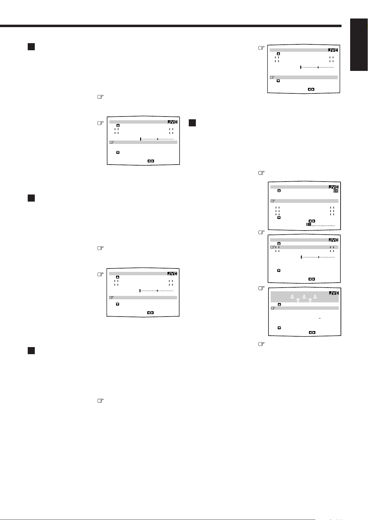
Listening at Low Volume (Loudness)
MAIN MENU
SOURCE :VCR1
VISUAL :VCR1
MODE :THEATER
SOUND CONTROL
TUNER CONTROL
SETTING
VOLUME : 20
:OPERATE
SURROUND LEVEL
:OPERATE
TEST TONE : OFF
CENTER LEVEL: 0
dB
REAR L LEVEL: +6
dB
REAR R LEVEL: 4dB
CENTER TONE : FLAT
DSP EFFECT : 3
SOUND CONTROL
SURROUND LEVEL
SEA
BAL.:R-21
LOUDNESS : OFF
INPUT ATT : NORMAL
SUBWFR LEVEL: 0
dB
NEXT PAGE
:ENTER
(Also see page 11)
1. Press MENU.
The MAIN MENU appears on the TV.
• Pressing one of the % / fi / @ / # buttons also displays the
MAIN MENU.
2. Press % / fi to move to “SOUND
CONTROL,” then press @ / #.
The SOUND CONTROL menu appears.
3. Press % / fi to move
to “LOUDNESS.”
4. Press @ / # to turn the
loudness “ON” or
“OFF.”
SOUND CONTROL
SURROUND LEVEL
SEA
BAL.:R-21
LOUDNESS : OFF
INPUT ATT : NORMAL
SUBWFR LEVEL: 0
NEXT PAGE
dB
:OPERATE
5. When you finish, press EXIT repeatedly until the
menu disappears from the TV.
Attenuating the Input Signal
(Also see page 11)
1. Press MENU.
The MAIN MENU appears on the TV.
• Pressing one of the % / fi / @ / # buttons also displays the
MAIN MENU.
2. Press % / fi to move to “SOUND
CONTROL,” then press @ / #.
The SOUND CONTROL menu appears.
3. Press % / fi to move
to “INPUT ATT.”
4. Press @ / # to turn the
Input Attenuator mode
“ATT ON” or
SOUND CONTROL
SURROUND LEVEL
SEA
BAL.:R-21
LOUDNESS : OFF
INPUT ATT : NORMAL
SUBWFR LEVEL: 0
NEXT PAGE
dB
:OPERATE
“NORMAL.”
5. When you finish, press EXIT repeatedly until the
menu disappears from the TV.
Adjusting the Subwoofer Output Level
(Also see page 11)
1. Press MENU.
The MAIN MENU appears on the TV.
• Pressing one of the % / fi / @ / # buttons also displays the
MAIN MENU.
2. Press % / fi to move to “SOUND
CONTROL,” then press @ / #.
The SOUND CONTROL menu appears.
3. Press % / fi to move
to “SUBWFR LEVEL.”
4. Press @ / # to adjust
the subwoofer output
level.
SOUND CONTROL
SURROUND LEVEL
SEA
BAL.:R-21
LOUDNESS : OFF
INPUT ATT : NORMAL
SUBWFR LEVEL: 0
NEXT PAGE
dB
:OPERATE
5. When you finish, press EXIT repeatedly until the
menu disappears from the TV.
Adjusting the DSP Modes
(Also see pages 23 – 27)
1. Press MENU.
The MAIN MENU appears on the TV.
• Pressing one of the % / fi / @ / # buttons also displays the
MAIN MENU.
2. Press % / fi to move to “MODE.”
3. Press @ / # to select the
DSP mode you want to
adjust.
• In this example,
“THEATER” is selected.
4. Press % / fi to move
to “SOUND
CONTROL,” then
press @ / #.
The SOUND CONTROL
menu appears.
5. Press % / fi to move
to “SURROUND
LEVEL,” then press
@ / #.
The SURROUND LEVEL
menu appears.
6. Press % / fi to move to the item you want to
set or adjust, then press @ / #.
On these adjustment menus, you can do the following:
For 3D-PHONIC (3D ACTION, 3D DIGITAL, 3D THEATER):
“DSP EFFECT”: Select the effect level.
For DAP (LIVE CLUB, DANCE CLUB, HALL, PAVILION):
“REAR L LEVEL”: Adjust the left rear speaker output
level. *
“REAR R LEVEL”: Adjust the right rear speaker output
level. *
“DSP EFFECT”: Select the effect level.
English
32
Page 36

English
SEA
SEA MODE :ROCK
SEA ADJUST
:OPERATE
100 10kHz1k
For Dolby Pro Logic:
“TEST TONE”: Output a test tone.
“CENTER LEVEL”: Adjust the center speaker output
level. **
“REAR L LEVEL”: Adjust the left rear speaker output
level. *
“REAR R LEVEL”: Adjust the right rear speaker output
level. *
“CENTER TONE”: Select the center tone level. **
For Dolby Digital, DTS Digital Surround, and MPEG
Multichannel:
“TEST TONE”: Output a test tone.
“CENTER LEVEL”: Adjust the center speaker output
level. **
“REAR L LEVEL”: Adjust the left rear speaker output
level. *
“REAR R LEVEL”: Adjust the right rear speaker output
level. *
“CENTER TONE”: Select the center tone level. **
For JVC Theater Surround:
“TEST TONE”: Output a test tone.
“CENTER LEVEL”: Adjust the center speaker output
level. **
“REAR L LEVEL”: Adjust the left rear speaker output
level. *
“REAR R LEVEL”: Adjust the right rear speaker output
level. *
“CENTER TONE”: Select the center tone level. **
“DSP EFFECT”: Select the effect level.
6. Press % / fi to move to the item you want to
set or adjust, then press @ / #.
On this adjustment menu, you can do the following:
“CENTER LEVEL”:Adjust the center speaker output level.
“REAR L LEVEL”: Adjust the left rear speaker output
level.
“REAR R LEVEL”: Adjust the right rear speaker output
level.
“CENTER TONE”: Select the center tone level.
7. When you finish, press EXIT repeatedly until the
menu disappears from the TV.
Selecting Your Favorite SEA Mode
(Also see page 19)
1. Press MENU.
The MAIN MENU appears on the TV.
• Pressing one of the % / fi / @ / # buttons also displays the
MAIN MENU.
2. Press % / fi to move to “SOUND
CONTROL,” then press @ / #.
The SOUND CONTROL menu appears.
3. Press % / fi to move
to “SEA,” then press @
/ #.
The SEA menu appears.
Notes:
*
Not displayed when “REAR SPK” is set to “NONE” (see page
14).
**
Not displayed when “CENTER SPK” is set to “NONE” (see
page 14).
7. When you finish, press EXIT repeatedly until the
menu disappears from the TV.
Activating the DVD MULTI Playback Mode
(Also see page 29)
1. Press MENU.
The MAIN MENU appears on the TV.
• Pressing one of the % / fi / @ / # buttons also displays the
MAIN MENU.
2. Press % / fi to move to “SOURCE.”
3. Press @ / # to select “DVD MULTI.”
4. Press % / fi to move
to “SOUND
CONTROL,” then press @ / #.
The SOUND CONTROL menu appears.
5. Press % / fi to move
to “SURROUND
LEVEL,” then press
@ / #.
The SURROUND LEVEL
menu appears.
SURROUND LEVEL
CENTER LEVEL: 0
REAR L LEVEL: +6
REAR R LEVEL: 4dB
CENTER TONE : FLAT
dB
dB
:OPERATE
4. Press % / fi to move
to “SEA MODE.”
5. Press @ / # to select the SEA mode you want.
6. When you finish, press EXIT repeatedly until the
menu disappears from the TV.
Creating Your Own SEA Mode
(Also see page 19)
1. Press MENU.
The MAIN MENU appears on the TV.
• Pressing one of the % / fi / @ / # buttons also displays the
MAIN MENU.
2. Press % / fi to move to “SOUND
CONTROL,” then press @ / #.
The SOUND CONTROL menu appears.
3. Press % / fi to move to “SEA,” then press
@ / #.
The SEA menu appears.
33
Page 37

4. Press % / fi to move
TUNER CONTROL
PRESET CH : 1
BAND :FM
FREQUENCY : 87.50
MHz
FM MODE :AUTO
PRESET MEMORY
:OPERATE
to “SEA ADJUST.”
SEA ADJUST
SEA USERMODE
The SEA ADJUST menu
appears.
5. Press % / fi / @ / # to
100 10kHz1k
SET
:MEMORY
adjust the SEA mode as
you want.
@ / # : Select the frequency ranges.
% / fi : Adjust the frequency levels.
6. Press SET to store the setting into the SEA
USERMODE.
• If you press EXIT, without pressing SET in this step, you can
return to the SEA menu. (The adjustment you have made is
active but not stored.)
7. When you finish, press EXIT repeatedly until the
menu disappears from the TV.
Setting the Basic Setting Items (Also see
pages 12 – 15)
1. Press MENU.
The MAIN MENU appears on the TV.
• Pressing one of the % / fi / @ / # buttons also displays the
MAIN MENU.
2. Press % / fi to move
to “SETTING,” then
press @ / #.
The SETTING 1 or SETTING
2 menu appears.
3. Press % / fi to move
SETTING 1
SUBWOOFER : NO
FRONT SPK : LARGE
CENTER SPK : SMALL
REAR SPK : LARGE
CNTR DELAY : 3msec
REAR DELAY : 5msec
CROSSOVER :100
NEXT PAGE
Hz
:ENTER
to the item you want to
set or adjust, then press
@ / #.
• To go to the SETTING 2
menu, move to “NEXT
PAGE,” then press @ / #.
• To go back to the SETTING
1 menu, move
“PREVIOUS PAGE,” then
press @ / #.
On the SETTING 1 and 2 menus, you can do the following:
to
SETTING 2
LFE ATT. : 0
COMP. : OFF
DIGITAL 1 : DBS
DIGITAL 2 : CD
DIGITAL 3 : MD
FL DISP. : NORMAL
PREVIOUS PAGE
dB
:ENTER
“LFE ATT.”: Set the low frequency effect attenuator
level (see page 15).
“COMP.”: Set the dynamic range compression
(see page 15).
“DIGITAL 1/2/3”: Set the digital input terminal
(see page 13).
“FL DISP.”: Shows the disc text information on the
display (see page 13).
Notes:
*
Not adjustable when “CENTER SPK” is set to “NONE” (see
page 14).
**
Not adjustable when “REAR SPK” is set to “NONE” (see page
14).
4. When you finish, press EXIT repeatedly until the
menu disappears from the TV.
Operating the Tuner (Also see pages 17 and 18)
1. Press MENU.
The MAIN MENU appears on the TV.
• Pressing one of the % / fi / @ / # buttons also displays the
MAIN MENU.
2. Press % / fi to move
to “TUNER
CONTROL,” then
press @ / #.
The TUNER CONTROL menu
appears.
3. Press % / fi to move to the item you want to
set or adjust, then press @ / #.
On the TUNER CONTROL menu, you can do the following:
“PRESET CH”: Select a preset channel station.
“BAND”: Select the band.
“FREQUENCY”: Tune in a station manually.
“FM MODE”: Select the FM reception mode.*
“PRESET MEMORY”: See “Storing the Preset Stations” on
the next page.
Note:
*
Not displayed when an AM station is selected.
4. When you finish, press EXIT repeatedly until the
menu disappears from the TV.
English
“SUBWOOFER”: Set the subwoofer information
“FRONT SPK”: Set the front speaker information
“CENTER SPK”: Set the center speaker information
“REAR SPK”: Set the rear speaker information
“CNTR DELAY”: Adjust the delay time of the center
“REAR DELAY”: Adjust the delay time of the rear
“CROSSOVER”: Set the crossover frequency
(see page 12).
(see page 14).
(see page 14).
(see page 14).
speaker output (see page 14). *
speaker output (see page 14). **
(see page 15).
34
Page 38

TUNER CONTROL
PRESET CH : 1 ABCD
BAND :FM
FREQUENCY : 87.50
MHz
FM MODE :AUTO
PRESET MEMORY
:ENTER
Storing the Preset Stations (Also see page 17)
English
1. Press MENU.
The MAIN MENU appears on the TV.
• Pressing one of the % / fi / @ / # buttons also displays the
MAIN MENU.
2. Press % / fi to move to “TUNER
CONTROL,” then press @ / #.
The TUNER CONTROL menu appears.
3. Tune into a station on the TUNER CONTROL
menu, referring to “Operating the Tuner” on the
previous page.
4. Press % / fi to move
to “PRESET
MEMORY,” then press
@ / #.
The PRESET MEMORY
menu appears.
PRESET MEMORY
FM 87.50
PRESET CH : CH 1
PRESET NAME: WABC
MHz
AUTO
5. Press @ / # to select a
preset station number
you want.
6. Press SET to store the setting.
7. When you finish, press EXIT repeatedly until the
menu disappears from the TV.
:MEMORY
SET
:OPERATE
6. Press % / fi to move
to “PRESET NAME,”
then press SET.
The character entry screen
appears.
7. Press % / fi / @ / # to
move
in front of a
character you want.
You can also select the following:
: To enter space
: To erase the character
: To go back to the previous character position or go
to the next character position
8. Press SET to enter the
selected character.
9. Repeat steps 7 and 8 to
enter up to four
characters.
10.Press % / fi / @ / # to
move
to “PRESET
NAME,” then press
SET to store the setting.
The TUNER CONTROL menu
appears again.
PRESET MEMORY
FM 87.50
PRESET CH : CH 1
PRESET NAME:
A B C D E F G H I J K
L M N O P Q R S T U V
W X Y Z
1 2 3 4 5 6 7 8 9 0
SPACE
PRESET MEMORY
FM 87.50
PRESET CH : CH 1
PRESET NAME: ABCD
A B C D E F G H I J K
L M N O P Q R S T U V
W X Y Z
1 2 3 4 5 6 7 8 9 0
SPACE
MHz
AUTO
SET
MHz
AUTO
:MEMORY
SET
:OPERATE
CANCEL
:ENTER
:OPERATE
CANCEL
Assigning Names to Preset Stations
(Also see page 18)
1. Press MENU.
The MAIN MENU appears on the TV.
• Pressing one of the % / fi / @ / # buttons also displays the
MAIN MENU.
2. Press % / fi to move to “TUNER
CONTROL,” then press @ / #.
The TUNER CONTROL menu appears.
3. Press % / fi to move to “PRESET CH.”
4. Press @ / # to select a preset station.
5. Press % / fi to move
to “PRESET
MEMORY,” then press
PRESET MEMORY
FM 87.50
PRESET CH : CH 1
PRESET NAME: WABC
MHz
AUTO
@ / #.
The PRESET MEMORY
menu appears.
SET
:MEMORY
:OPERATE
11.When you finish, press EXIT repeatedly until the
menu disappears from the TV.
35
Page 39

COMPU LINK Remote Control System
The COMPU LINK remote control system allows you to operate JVC audio components through the remote sensor on
the receiver.
To use this remote control system, you need to connect JVC audio
components through the COMPU LINK-3 (SYNCHRO) jacks (see
below) in addition to the connections using cables with RCA pin
plugs (see pages 5 and 6).
• Make sure that the AC power cords of these components are
unplugged before connection. Plug the AC power cords only after
all connections are complete.
CD player
Cassette deck
or
MD recorder
COMPU LINK – 3
(SYNCHRO)
Turntable
Notes:
• If your audio component has two COMPU LINK-3 (SYNCHRO)
jacks, you can use either one. If it has only one COMPU LINK-3
(SYNCHRO) jack, connect it so that it is the last item in the series
of components. (For example, the turntable or CD player in the
diagram above.)
• To operate the cassette deck or MD recorder using the COMPU
LINK remote control system, set the source name correctly. (See
page 12.)
• Refer also to the manuals supplied with your audio components.
This remote control system allows you to use four functions listed
below.
Remote Control through the Remote Sensor on the
Receiver
You can control the connected audio components through the remote
sensor on the receiver using this remote control. Aim the remote
control directly at the remote sensor on the receiver. For details, see
pages 42 and 43.
Automatic Power On/Off (Standby): only possible
with the COMPU LINK-3 connection
Both the CD player and cassette deck (or MD recorder) turn on and
off (standby) along with the receiver.
When you turn on the receiver, the CD player or cassette deck (or
MD recorder) will turn on automatically, depending on which
component has been previously selected.
When you turn off the receiver, both the CD player and cassette
deck (or MD recorder) will turn off (standby).
Synchronized Recording
Synchronized recording means the cassette deck (or MD recorder)
starts recording as soon as a CD or a record begins playing.
To use synchronized recording, follow these steps:
1. Put a tape in the cassette deck (or an MD in the
MD recorder), and a disc in the CD player (or a
record on the turntable).
2. Press the record (¶) button and the pause (8)
button on the cassette deck (or MD recorder) at
the same time.
This puts the cassette deck (or MD recorder) into recording
pause.
If you do not press the record (¶) button and pause (8) button at
the same time, the synchronized recording feature will not
operate.
3. Press the play (3) button on the CD player or on
the turntable.
The source changes on the receiver, and as soon as play starts,
the cassette deck (or MD recorder) starts recording. When the
play ends, the cassette deck (or MD recorder) enters recording
pause, and stops about 4 seconds later.
Notes:
• During synchronized recording, the selected source cannot be
changed.
• If the power of any component is shut off during synchronized
recording, the COMPU LINK remote control system may not
operate properly. In this case, you must start again from the
beginning.
English
Automatic Source Selection
When you press the play (
on its own remote control, the receiver automatically turns on and
changes the source to the component. On the other hand, if you
select a new source on the receiver or on the remote control, the
selected component begins playing immediately.
In both cases, the previously selected source continues playing
without sound for a few seconds.
33
3) button on a connected component or
33
36
Page 40

TEXT COMPU LINK Remote Control System
The TEXT COMPU LINK remote control system has been newly developed to deal with the disc information recorded in
the CD Text* and MDs. Using these information in the discs, you can operate the CD player or MD recorder equipped
with the TEXT COMPU LINK remote control system through the receiver.
English
CONNECTIONS:
To use this remote control system, you need to connect the CD
player and/or MD recorder you want to operate, following the
procedures below.
1. If you have already plugged your CD player, MD
recorder, and this receiver into the AC outlets,
unplug their AC power cords first.
2. Connect your CD player, MD recorder, and this
receiver as follows, through the COMPU LINK-3
(SYNCHRO) jacks and TEXT COMPU LINK
jacks.
1) COMPU LINK-3 (SYNCHRO) jacks: Use the cables with
the monaural mini-plugs (not supplied with this receiver).
CD player
MD recorder
COMPU LINK – 3
(SYNCHRO)
2) TEXT COMPU LINK jacks: Use the cables with the
stereo mini-plugs (not supplied with this receiver).
CD player
MD recorder
TEXT
COMPU LINK
1(MASTER UNIT)
2(SLAVE UNIT)
IMPORTANT:
Set the Master/Slave Selector on the rear to “1(MASTER UNIT).”
• “2(SLAVE UNIT)” is just for the serviceman’s use. The TEXT
COMPU LINK remote control system does not function with the
selector set to “2(SLAVE UNIT).”
3. Connect your CD player, MD recorder and this
receiver, using the cables with RCA pin plugs (see
page 6).
FUNCTIONS:
This remote control system allows you to use the functions listed
below.
Displaying the Disc Information on the TV screen
Disc information such as its performer and disc title (and track titles
only when a CD Text is selected) is shown on the TV screen.
Disc Search: Only for CD Player
This remote control system can allow you to search discs by the
performer, disc title, and music genre.
With this disc search, you can easily find the disc you want to play.
Disc Title Input
If your CD player or MD recorder has the disc memory function,
you can input the following information about the normal audio CDs
or MDs on the TV screen.
• For CDs: Performer, disc title, and music genre
• For MDs: Disc title and song titles
*What is a CD Text?
In a CD Text, some information about the disc (its disc title, performer,
composer, arranger, etc.) is recorded.
Notes:
• If your audio component has two COMPU LINK-3 (SYNCHRO)
jacks, you can use either one. If it has only one COMPU LINK-3
(SYNCHRO) jack, connect it so that it is the last item in the series
of components. (For example, the CD player in the diagram to the
left.)
• If your audio component has two TEXT COMPU LINK jacks, you
can use either one. If it has only one TEXT COMPU LINK jack,
connect it so that it is the last item in the series of components. (For
example, the CD player in the diagram to the left.)
• “TEXT COMPULINK SOURCE NOT CONNECTED” appears on the
display in the following cases:
– When the connections explained to the left are not correctly done.
– When you try to use the TEXT COMPU LINK function a few
seconds after you turn on the connected equipment. This is not a
malfunction of the units.
• Refer also to the manuals supplied with your CD player or MD
recorder.
IMPORTANT:
If you turn on the receiver before turning on the other components
after connecting the components, the TEXT COMPU LINK remote
control system does not work correctly.
If this happens:
1. Turn off all the components including this receiver.
2. Turn on the connected components.
3. Turn on this receiver.
4. Plug the AC power cords of these components
above into the AC outlets.
5. When turning on these components for the first
time, turn on the connected components first,
then turn on this receiver.
37
Page 41
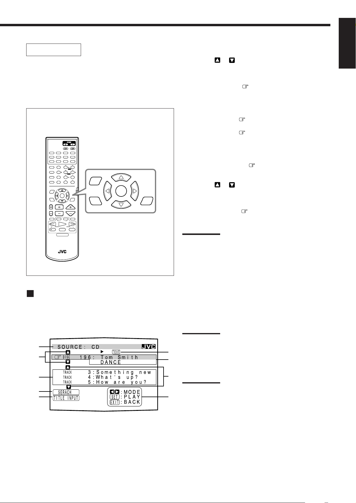
OPERATIONS
To use this remote control system, you need to connect the TV to the
MONITOR OUT jack on the rear panel (see page 7), and set the
TV’s input mode to the proper position to which the receiver is
connected. Make sure you have connected the CD player or
MD recorder equipped with the TEXT COMPU LINK
remote control system. If not, you cannot use the
following functions.
On-Screen Operation buttons (on the remote control)
TV/CATV/DBS
ANALOG/DIGITAL
CNTR
123
MENU
TEST REAR-L
456
ENTER
EFFECT REAR-R
7
/P
89
SUBWOOFER
SEA MODE
10
0
RETURN
FM MODE/MUTING
SET
CHANNEL VOLUMETV VOL
VCR 1
TAPE
CONTROL
PLAY
PTY SEARCH
STOP PAUSE
DISPLAY MODE
VCR 1
SLEEP
+10
100+
AUDIO/
TV/VCR
CATV/DBS
TEXT
DISPLAY
MUTING
FF/
MENU
EXIT
SET
TEXT
DISPLAY
DVD DVD MUILTI CD TAPE/MD
TV/DBS VIDEO PHONO FM/AM
VCR 1 VCR 2
SURROUND CNTR TONE
ON/OFF
SURROUND
MODE
DISC
SOUND
MENU
EXIT
TV/VIDEO
/REW
PTY PTY
REC
RM-SRX889P REMOTE CONTROL
Showing the Disc Information on the TV
Screen
Press TEXT DISPLAY while “CD” or “MD” is
selected as the source.
The Disc Information screen appears on the TV.
1
2
3
4
5
6
7
8
9
1 Source name: CD or MD
2 Select
or , then press SET to change the disc.
3 Track numbers and track titles.
• The current playing (selected) track is indicated in
yellow.
• When you move
to a track number, you can
change the track information by pressing @ / #. Each
time you press the button, track information alternates
between its track title and its performer. (You can also
start playing the track by pressing SET.)
4 Select this (move
in front), then press SET to go to
the DISC SEARCH screen (see page 39).
5 Select this (move in front), then press SET to go to
the TITLE INPUT screen (see page 40).
6 This appears only when a CD Text is selected.
7 Disc information such as the disc title, performer, and
music genre.
When this is selected (
in front), you can change the
disc information by pressing @ / #. Each time you press
the button, disc information (see “Note on 7”) changes.
8 Select
or , then press SET to change the track.
9 Usable buttons and their functions for the current
selection.
Indication here will be changed according to what is
currently selected ( in front) on the screen. See “Note
on 9.”
Note on 7:
The following information will appear on the display:
For CDs:
• Disc title
• Performer
• Genre
• Song writer
• Composer
• Arranger
• Message
For MDs:
• Disc title
Only recorded information will be shown. If there is no data, “NO
DATA” will appear.
Note on 9:
For example, the SET button will be used to start play (PLAY), to go to
the next screen (ENTER), and to determine the selection (ENTER).
To exit from the Disc information screen:
Press EXIT.
Notes:
• The on-screen display will disappear in the following case:
– if no operation is done for about 10 minutes.
– if you do any operation other than explained in this section.
• To control the MD recorder using the TEXT COMPU LINK remote
control system, you have to change the source name shown on the
display from “TAPE” to “MD.” (See page 12.)
• Some special characters and marks cannot be displayed correctly.
English
38
Page 42
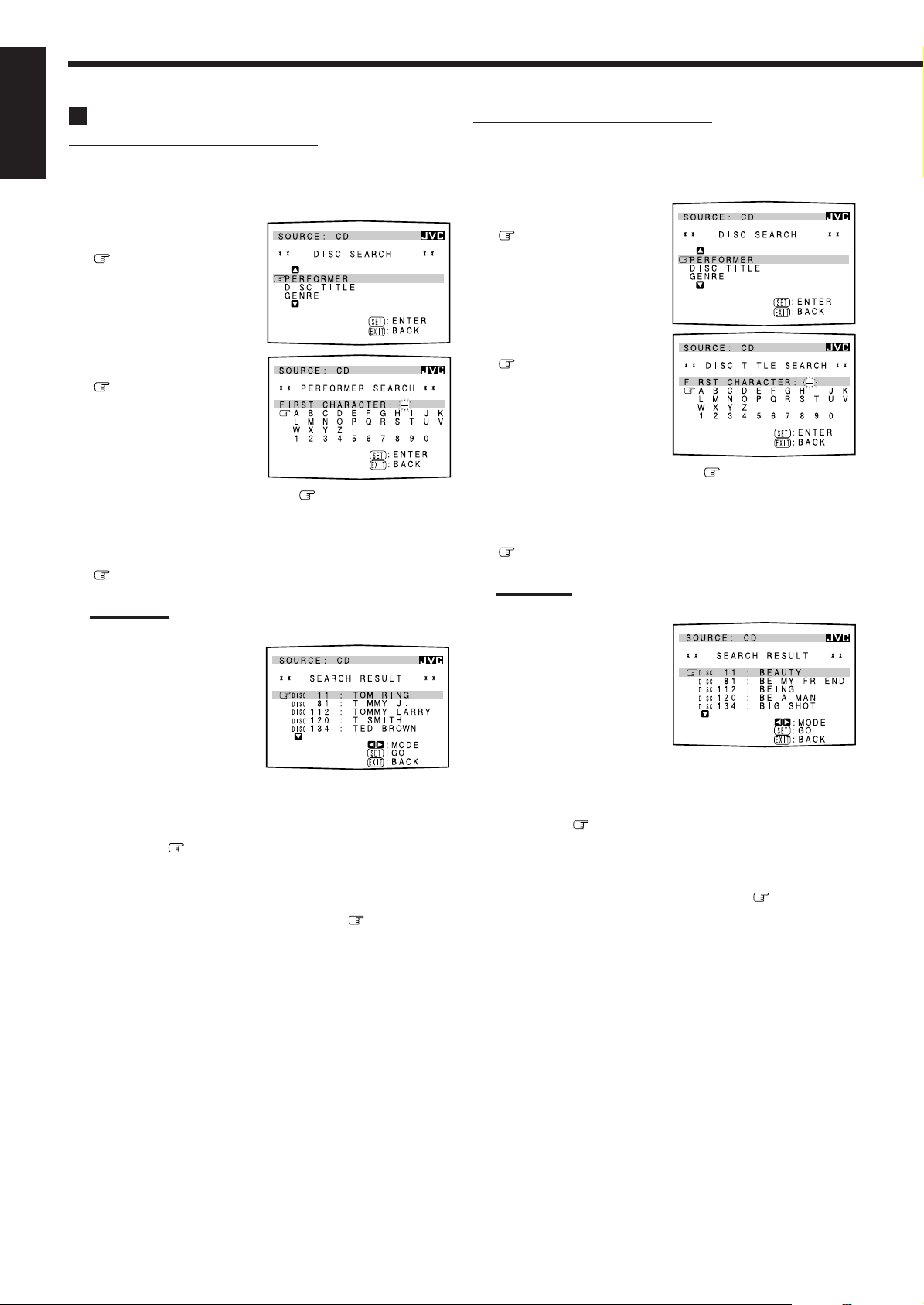
Searching for a Disc (Only for the CD player)
Search for a disc by its performer:
English
1. Press TEXT DISPLAY while “CD” is selected as
the source.
The Disc Information screen appears on the TV.
2. Press % / fi to move
to “SEARCH,” then
press SET.
The DISC SEARCH screen
appears .
3. Press % / fi to move
to “PERFORMER”,
then press SET.
The PERFORMER SEARCH
screen appears.
4. Press % / fi / @ / # to move in front of the
first character of the performer you want to
search, then press SET.
To correct the incorrect entry, press % / fi / @ / # to move
in front of the correct character, then press SET.
Note:
Symbols such as @, # or $ cannot be available for search.
5. Press SET again.
Disc search starts, then the
SEARCH RESULT screen,
showing the performers,
appears.
Search for a disc by its disc title:
1. Press TEXT DISPLAY while “CD” is selected as
the source.
The Disc Information screen appears on the TV.
2. Press % / fi to move
to “SEARCH,” then
press SET.
The DISC SEARCH screen
appears.
3. Press % / fi to move
to “DISC TITLE,
then press SET.
The DISC TITLE SEARCH
screen appears.
4. Press % / fi / @ / # to move in front of the
first character of the disc title you want to search,
then press SET.
To correct the incorrect entry, press % / fi / @ / # to move
in front of the correct character, then press SET.
Note:
Symbols such as @, # or $ cannot be available for search.
5. Press SET again.
Disc search starts, then the
SEARCH RESULT screen,
showing the disc titles,
appears.
6. On the SEARCH RESULT screen, you can do the
following:
• Changing the indication of the disc information: Press % /
fi to move
you press @ / #, the disc information alternates between its
performer and its disc title.
• Starting a disc play and going to the Disc Information
screen (see page 38): Press % / fi to move
disc, then press SET.
• Showing unseen disc information (if more than 5 discs are
listed as a result of the search): Press % / fi until they
appear.
• Going back to the PERFORMER SEARCH screen: Press
EXIT.
to a searched disc, then press @ / #. Each time
to a searched
6. On the SEARCH RESULT screen, you can do the
following:
• Changing the indication of the disc information: Press % /
fi to move
you press @ / #, the disc information alternates between its
disc title and its performer.
• Starting a disc play and going to the Disc Information
screen (see page 38): Press % / fi to move
disc, then press SET.
• Showing unseen disc information (if more than 5 discs are
listed as a result of the search): Press % / fi until they
appear.
• Going back to the DISC TITLE SEARCH screen: Press
EXIT .
to a searched disc, then press @ / #. Each time
to a searched
39
Page 43

Search for a disc by its genre:
1. Press TEXT DISPLAY while “CD” is selected as
the source.
The Disc Information screen appears on the TV.
2. Press % / fi to move
to “SEARCH,”
then press SET.
The DISC SEARCH screen
appears.
Entering the Disc Information
For the CD Player with the disc memory function:
You can use the disc memory function through this receiver.
The disc information (its performer, disc title, and music genre) of
normal audio CDs will be stored into the memory built in the CD
player.
For the disc memory function, refer to the manual supplied with your
CD player.
• The performer, disc title, and music genre information are usually
recorded in a CD Text. However, if a CD Text has no genre
information recorded in the disc itself, you can input its music
genre by yourself.
English
3. Press % / fi to move
to “GENRE”, then
press SET.
The GENRE SEARCH
screen appears.
4. Press % / fi to move to the genre you want to
search, then press SET.
To show the unseen genres, press % / fi until they appear.
Disc search starts, then the
SEARCH RESULT screen,
showing the disc titles,
appears.
5. On the SEARCH
RESULT screen, you
can do the following:
• Changing the indication of the disc information: Press % /
fi to move
time you press @ / #, the disc information alternates
between its disc title and its performer.
• Starting a disc play and going to the Disc Information
screen (see page 38): Press % / fi to move to a searched
disc, then press SET.
• Showing unseen disc information (if more than 5 discs are
listed as a result of the search): Press % / fi until they
appear.
• Going back to the GENRE SEARCH screen: Press EXIT.
to a searched disc, then press @ / #. Each
Note:
You can enter the TITLE INPUT screens for a CD Text and input its
titles. However, you cannot store the titles you have input for a CD
Text.
Example: Entering the following information for Disc 1
Performer: “MICHAEL”
Disc title: “MY FAVORITE”
1. Press TEXT DISPLAY while “CD” is selected as
the source.
The Disc Information screen appears on the TV.
2. Press % / fi to move
to “TITLE INPUT,”
then press SET.
The TITLE INPUT:
PERFORMER screen appears.
3. Press % / fi / @ / # to move in front of a
character you want, then press SET to enter the
character.
• If the current CD is a CD Text, go to step 5 without entering the
performer.
To use the lower case letters, press % / fi / @ / # to move
to , then press SET.
To use the upper case letters again, press % /
fi / @ / # to move to , then press SET.
40
Page 44

4. Repeat step 3 until you
English
finish putting a
performer name (up to
32 characters).
To insert a space, press % / fi
/ @ / # to move
, then press SET.
To correct an incorrect character:
1) Press % / fi / @ / # to move to + or =, then press
SET until the incorrect character is selected.
2) Press % / fi / @ / # to move to , then press SET
to erase the character.
3) Press % / fi / @ / # to move in front of the correct
character, then press SET to enter a correct character.
For the MD recorder:
You can write the disc information (disc title and song titles) into the
to
disc. You can only write the song title for the song currently
selected.
• If you have the CD-MD combination deck, you can also enter the
disc information (its performer, disc title, and its music genre) of
normal audio CDs into the memory built in the CD-MD
combination deck. (To do this, follow the procedure of “For the
CD Player with the disc memory function” to the left.)
• If you change the disc or song title with more than 32 characters,
the characters following the 32nd will be erased from the title.
1. Press TEXT DISPLAY while “MD” is selected as
the source.
The Disc Information screen appears on the TV.
5. Press % / fi / @ / # to
move
MICHAEL (in this
to “DISC 1:
example),” then press
SET.
The TITLE INPUT: DISC
TITLE screen appears.
6. Enter the disc title,
referring to steps 3 and
4.
• If the current CD is a CD
Text, go to the next step
without entering the disc
title.
7. Press % / fi / @ / # to
move
to “DISC 1:
MY FAVORITE (in this
example),” then press
SET.
The TITLE INPUT: DISC 1
GENRE screen appears.
8. Press % / fi to move to the genre you want,
then press SET.
The Disc Information screen appears again.
To show the unseen genres, press % / fi until they appear.
2. Press % / fi to move
to “TITLE INPUT,”
then press SET.
The DISC TITLE INPUT
screen appears.
3. Enter the title, referring
to steps 3 and 4 of “For
the CD Player with the
disc memory function”
to the left.
• You can enter up to 32
characters for the disc title.
4. Press % / fi / @ / # to
move
to the disc title
you have just entered,
then press SET.
The disc title is stored into the
memory, and the SONG
TITLE INPUT screen for the
currently selected song
appears.
• You can enter a song title for the song currently selected
(indicated in yellow on the TV screen).
5. Enter the song title, referring to steps 3 and 4 of
“For the CD Player with the disc memory
function” to the left.
• You can enter up to 32 characters for the song title.
6. Press % / fi / @ / # to move to the song title
you have just entered, then press SET.
The song title is stored into the memory, and the Disc
Information screen appears again.
41
Page 45
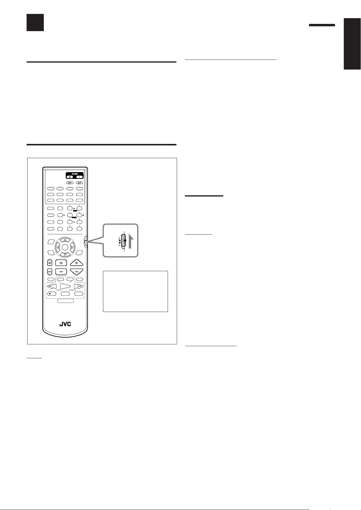
Operating JVC’s Audio/Video Components
You can operate JVC’s audio and video components with this receiver’s remote control, since control signals for JVC
components are preset in the remote control.
IMPORT ANT:
To operate JVC’s audio components using this remote control:
• You need to connect JVC audio components through the COMPU
LINK-3 (SYNCHRO) jacks (see page 36) in addition to the
connections using cables with RCA pin plugs (see pages 5 and 6).
• Aim the remote control directly at the remote sensor on the receiver.
• If you use the buttons on the front panel or the menu function to
choose a source, the remote control will not operate that source. To
operate a source with the remote control, the source must be
selected using source selecting buttons on the remote control.
• To operate the cassette deck or MD recorder using the COMPU
LINK remote control system, set the source name correctly. (See
page 12.)
• Refer also to the manuals supplied with your components.
TV/CATV/DBS
DVD DVD MUILTI CD TAPE/MD
TV/DBS VIDEO PHONO FM/AM
VCR 1 VCR 2
SURROUND CNTR TONE
ON/OFF
TEST REAR-L
SURROUND
MODE
DISC
EFFECT REAR-R
7
SOUND
SEA MODE
10
RETURN
MENU
EXIT
CHANNEL VOLUMETV V OL
TV/VIDEO
VCR 1
/REW
REC
RM-SRX889P REMOTE CONTROL
VCR 1
ANALOG/DIGITAL
SLEEP
CNTR
123
MENUMENU
456
ENTERENTER
/P 89
SUBWOOFER
+10
0
FM MODE/MUTING
100+
AUDIO/
TV/VCR
CATV/DBS
SET
TEXT
DISPLAY
TAPE
MUTING
CONTROL
FF/
PLAY
TUNINGDOWN UP
STOP PAUSE
AUDIO/
TV/VCR
CATV/DBS
Check to see if its remote
control mode selector is set
to the correct position.
To operate the audio
system, TVs, and VCRs,
set it to “AUDIO/TV/VCR.”
Sound control section (Amplifier)
You can always perform the following operations (with the remote
control mode selector set to “AUDIO/TV/VCR”):
SURROUND ON/OFF:Turns on or off the Surround modes —
Dolby Pro Logic, Dolby Digital, DTS
Digital Surround, and MPEG Multichannel.
SURROUND MODE: Selects the DSP modes.
After pressing SOUND (with the remote control mode selector set to
“AUDIO/TV/VCR”), you can perform the following operations:
SEA MODE: Changes the SEA modes.
SUBWOOFER – / +: Adjusts the subwoofer output level.
CNTR – / +: Adjusts the center speaker output level.
REAR•L – / +: Adjusts the left rear speaker output level.
REAR•R – / +: Adjusts the right rear speaker output level.
EFFECT: Selects the effect level.
TEST: Turns on or off the test tone output.
CNTR TONE: Selects the center tone.
Note:
After adjusting sounds, press the corresponding source selecting
button or DISC to operate your target source by using the 10 keys;
otherwise, the 10 keys cannot be used for operating your target
source.
CD player
After pressing CD (with the remote control mode selector set to
“AUDIO/TV/VCR”), you can perform the following operations on
the CD player:
PLAY: Starts playing.
44
4: Returns to the beginning of the current (or
44
previous) track.
¢¢
¢: Skips to the beginning of the next track.
¢¢
STOP: Stops playing.
PAUSE: Pauses playing. To release it, press PLAY.
1 – 10, +10: Selects a track number directly.
For track number 5, press 5.
For track number 15, press +10, then 5.
For track number 20, press +10, then 10.
For track number 30, press +10, +10, then 10.
English
Tuner
After pressing FM/AM (with the remote control mode selector set to
“AUDIO/TV/VCR”), you can perform the following operations:
FM/AM: Alternates between FM and AM.
1 – 10, +10: Selects a preset channel number directly.
For channel number 5, press 5.
For channel number 15, press +10, then 5.
For channel number 20, press +10, then 10.
TUNING UP/TUNING DOWN:
Tunes into stations.
FM MODE/MUTING: Changes the FM reception mode.
CD player-changer
After pressing DISC (with the remote control mode selector set to
“AUDIO/TV/VCR”), you can perform the following operations on a
CD player-changer:
PLAY: Starts playing.
44
4: Returns to the beginning of the current (or previous)
44
track.
¢¢
¢: Skips to the beginning of the next track.
¢¢
STOP: Stops playing.
PAUSE: Pauses playing. To release it, press PLAY.
1 – 6, 7/P: Selects the number of a disc installed in a CD
player-changer.
After pressing CD (with the remote control mode selector set to
“AUDIO/TV/VCR”), you can perform the following operations on
the CD player-changer:
1 – 10, +10: Selects a track number directly.
For track number 5, press 5.
For track number 15, press +10, then 5.
For track number 20, press +10, then 10.
For track number 30, press +10, +10, then 10.
42
Page 46
Turntable
After pressing PHONO (with the remote control mode selector set to
English
“AUDIO/TV/VCR”), you can perform the following operations on a
turntable:
PLA Y : Starts playing.
STOP: Stops operations.
Cassette deck
After pressing TAPE/MD or TAPE CONTROL (with the remote
control mode selector set to “AUDIO/TV/VCR”), you can perform
the following operations on a cassette deck:
PLA Y : Starts playing.
11
1: Fast winds the tape from right to left.
11
¡¡
¡: Fast winds the tape from left to right.
¡¡
STOP: Stops operations.
PAUSE: Pauses playing. To release it, press PLAY.
¶ REC: Press this button with the PLAY button to start
recording.
Press this button with the PAUSE button to enter
recording pause.
MD recorder
After pressing TAPE/MD or TAPE CONTROL (with the remote
control mode selector set to “AUDIO/TV/VCR”), you can perform
the following operations on the MD recorder:
PLA Y : Starts playing.
4: Returns to the beginning of the current (or previous)
track.
¢: Skips to the beginning of the next track.
STOP: Stops playing.
PAUSE: Pauses playing. To release it, press PLAY.
¶ REC: Press this button with the PLAY button to start
recording.
Press this button with the PAUSE button to enter
recording pause.
VCR
You can always perform the following operations (with the remote
control mode selector set to “AUDIO/TV/VCR”):
VCR 1 : Turns on or off the VCR.
After pressing VCR 1 or VCR 1 CONTROL (with the remote
control mode selector set to “AUDIO/TV/VCR”), you can perform
the following operations on the VCR:
1 – 9, 0: Selects the TV channels on VCR.
PLA Y : Starts playing.
1: Rewinds a tape.
¡: Fast winds a tape.
STOP: Stops operations.
PAUSE: Pauses playing. To release it, press PLAY.
¶ REC: Press this button with the PLAY button to start
recording.
Press this button with the PAUSE button to enter
recording pause.
CHANNEL +/–: Changes the TV channels on the VCR.
Note:
You can use either VCR 1 button or the VCR 1 CONTROL button to
activate the buttons listed above. If you press VCR 1, the playing
source also changes. On the other hand, if you press VCR 1
CONTROL, the playing source does not change.
DVD player
After pressing DVD or DVD MULTI (with the remote control mode
selector set to “AUDIO/TV/VCR”), you can perform the following
operations on a DVD player:
PLA Y : Starts playing.
4: Returns to the beginning of the current (or previous) track.
¢: Skips to the beginning of the next track.
STOP: Stops playing.
PAUSE: Stops playing temporarily. To release it, press PLAY.
Note:
You can use either TAPE/MD button or the TAPE CONTROL button to
activate the buttons listed above. If you press TAPE/MD, the playing
source also changes. On the other hand, if you press TAPE
CONTROL, the playing source does not change.
IMPORTANT:
To operate JVC’s video components using this remote control:
• Aim the remote control directly at the remote sensor on the VCR,
DVD player or TV, not on the receiver.
• Some JVC VCRs can accept two types of the control signals —
remote code “A” and “B.” Before using this remote control, make
sure that the remote control code of the target VCR is set to code
“A.”
After pressing DVD or DVD
MULTI, these buttons can be used
for the DVD menu operations.
TEST REAR-L
Note:
For detailed menu operations, refer to the
instructions supplied with the discs or the
DVD player.
456
CNTR
23
MENUMENU
ENTERENTER
REAR-R
8
TV
You can always perform the following operations (with the remote
control mode selector set to “AUDIO/TV/VCR”):
TV/CATV/DBS
: Turns on or off the TV.
TV VOL +/–: Adjusts the volume.
TV/VIDEO: Sets the input mode (either TV or VIDEO).
After pressing TV/DBS (with the remote control mode selector set
to “AUDIO/TV/VCR”), you can perform the following operations
on a TV:
CHANNEL +/–: Changes the channels.
1 – 9, 0, 100+: Selects the channels.
RETURN: Alternates between the previously selected channel
and the current channel.
43
Page 47
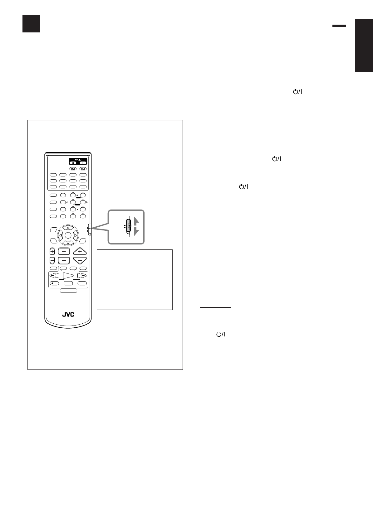
Operating Other Manufacturers’ Video Equipment
This remote control supplied with the receiver can transmit control
signals for other manufacturers’ VCRs, TVs, CATV converters and
DBS tuners. By changing the transmittable signals from preset ones
to the other manufacturers’, you can operate the other
manufacturer’s components using this remote control.
When operating the other manufacturers’ components, refer also to
the manuals supplied with them. To operate these components with
the remote control, first you need to set the manufacturer’s code
each for VCR, TV, CATV converters, and DBS tuner.
TV/CATV/DBS
DVD DVD MUILTI CD TAPE/MD
TV/DBS VIDEO PHONO FM/AM
VCR 1 VCR 2
SURROUND CNTR TONE
ON/OFF
TEST REAR-L
SURROUND
MODE
DISC
EFFECT REAR-R
7
SOUND
SEA MODE
RETURN
MENU
EXIT
VCR 1
ANALOG/DIGITAL
SLEEP
CNTR
123
MENUMENU
456
ENTERENTER
/P 89
SUBWOOFER
0
FM MODE/MUTING
SET
+10
100+
AUDIO/
TV/VCR
CATV/DBS
TEXT
DISPLAY
10
AUDIO/
TV/VCR
CATV/DBS
To change the transmittable signals for
operating another manufacturer’s TV
1. Set the remote control mode to “AUDIO/TV/
VCR.”
2. Press and hold TV/CATV/DBS .
3. Press TV/DBS.
4. Enter manufacturer’s code (three digits) using
buttons 1 – 9, and 0.
See the list on pages 46 and 47 to find the code.
Examples: For a JVC product, press 0, 3, then 6.
For a Hitachi product, press 0, 3, then 6.
5. Release TV/CA TV/DBS .
The following buttons can be used for operating the TV (with
the remote control mode selector set to “AUDIO/TV/VCR”):
TV/CATV/DBS
TV VOL +/–: Adjusts the volume.
TV/VIDEO: Sets the input mode (either TV
After pressing TV/DBS (with the remote control mode selector
set to “AUDIO/TV/VCR”), you can perform the following
operations on a TV:
:
Turns on and off the TV.
or VIDEO).
English
CHANNEL VOLUMETV V OL
VCR 1
TV/VIDEO
CONTROL
/REW
PLAY
TUNINGDOWN UP
STOP PAUSE
REC
RM-SRX889P REMOTE CONTROL
Check to see if its remote
control mode selector is set to
TAPE
MUTING
FF/
the correct position.
To operate the audio
system, TVs, and VCRs, set it
to “AUDIO/TV/VCR.”
To operate the CATV
CHANNEL +/–: Changes the channels.
1 – 10, 0, 100+ (+10): Selects the channels.
100+ (+10) button will function as
the ENTER button if your TV requires
pressing ENTER after selecting a
channel number.
converter and DBS tuner, set
it to “CATV/DBS.”
Note:
Refer to the manual supplied with your TV.
6. Try to operate your TV by pressing TV/CATV/
DBS
When your TV turns on or off, you have entered the correct
code.
If there are more than one code listed for your brand of TV,
try each one until the correct one is entered.
.
44
Page 48

To change the transmittable signals for
English
operating a CATV converter or DBS tuner
To change the transmittable signals for
operating another manufacturer’s VCR
1. Set the remote control mode to “CATV/DBS.”
2. Press and hold TV/CATV/DBS
.
3. Press TV/DBS.
4. Enter manufacturer’s code (three digits) using
buttons 1 – 9, and 0.
See the list on pages 47 and 48 to find the code.
Examples: For a Marantz product, press 2, 0, then 0.
For a Philips product, press 2, 0, then 0.
5. Release TV/CA TV/DBS .
After setting the remote control mode selector to “CATV/DBS,”
you can perform the following operations on the CATV
convertor or on the DBS tuner:
TV/CATV/DBS
CHANNEL +/–: Changes the channels.
1 – 10, 0, 100+ (+10): Selects the channel.
Note:
Refer to the manual supplied with your CATV converter or DBS
tuner.
: Turns on and off the CATV converter
or DBS tuner.
100+ (+10) button will function as the
ENTER button if your equipment
requires pressing ENTER after
selecting a channel number.
6. Try to operate your CATV converter or DBS
tuner by pressing TV/CATV/DBS
When your CATV converter or DBS tuner turns on or off, you
have entered the correct code.
If there are more than one code listed for your brand of
CATV converter or DBS tuner, try each one until the correct
one is entered.
.
1. Set the remote control mode to “AUDIO/TV/
VCR.”
2. Press and hold VCR 1
.
3. Press VCR 1.
4. Enter manufacturer’s code (three digits) using
buttons 1 – 9, and 0.
See the list on pages 48 and 49 to find the code.
Examples: For a JVC product, press 0, 0, then 8.
For a Funai product, press 0, 0, then 0.
5. Release VCR 1 .
Following button can be used for operating the VCR (with the
remote control mode selector set to “AUDIO/TV/VCR”):
VCR 1
After pressing VCR 1 or VCR 1 CONTROL (with the remote
control mode selector set to “AUDIO/TV/VCR”), you can
perform the following operations on the VCR:
CHANNEL +/–: Changes the TV channels on the VCR.
1 – 10, 0, 100+ (+10): Selects the TV channels.
PLAY: Starts playback.
1: Rewinds a video tape.
¡: Fast winds a video tape.
STOP: Stops operation.
PAUSE: Pauses.
¶ REC: Starts recording or enters recording pause.
Notes:
• Refer to the manual supplied with your VCR.
• You can use either VCR 1 button or the VCR 1 CONTROL
button to activate the buttons listed above. If you press VCR 1,
the playing source also changes. On the other hand, if you
press VCR 1 CONTROL, the playing source does not change.
: Turns on and off the VCR.
100+ (+10) button will function as
the ENTER button if your VCR
requires pressing ENTER after
selecting a channel number.
45
6. Try to operate your VCR by pressing VCR 1 .
When your VCR turns on or off, you have entered the correct
code.
If there are more than one code listed for your brand of
VCR, try each one until the correct one is entered.
Page 49

Manufacturers’ codes for TV
A-Mark 003
Acura 009
Admiral 093
Aiko 092
Akai 030, 208
Akura 264
Alaron 216
Alba 009, 036, 037
Amstrad 009, 037
Anam 003, 004, 009, 068, 161, 250, 425, 426
Anam National 161, 250, 425
Anitech 009, 068
AOC 003, 030
Arcam 216
Archer 003
Audinac 391
Audiosonic 037
Audiovox 003, 092, 451
Basic Line 009
Baur 037, 535, 554
Bell & Howell 154
Beon 037
Blaupunkt 535, 554
Britannia 216
Broksonic 003, 426
Bush 009, 036, 037
Candle 030, 186
Carnivale 030
Carrefour 036
Carver 054, 170
Cascade 009
Cathay 037
CCE 037
Celebrity 000
Centurion 037
Cimline 009
Cineral 092, 451
Citizen 030, 039, 060, 092, 186
Clarivox 037
Contec 009, 036, 216
Continental Edison 489
Craig 161
Crosley 054
Crown 009, 037, 039
CS Electronics 216
Curtis Mathes 030, 039, 047, 054, 060, 093, 145, 154,
166, 451
Daewoo 009, 037, 039, 066, 092, 154, 391, 402,
451
Dansai 037
Dayton 009
De Graaf 208
Decca 037
Denon 145
Dixi 004, 009, 037
ECE 037
Ectec 391
Electroband 000
Electrohome 409
Elin 037
Elta 009
Emerson 039, 154, 178
Envision 030
Erres 037
Etron 009, 283
Ferguson 037, 560
Fidelity 216
Finlandia 208
Finlux 037
Firstline 009, 216
Fisher 154, 208
Formenti 037
Fortress 093
Frontech 264
Funai 264, 342
GE 047, 093, 178, 451
GEC 037
Geloso 009
General 186
Gibralter 030
GoldStar 001, 002, 030, 037, 039, 178, 283, 409,
457, 467
Goodmans 036, 037
Gradiente 053, 170
Granada 037, 208, 502
Grundig 037, 535, 554
Hallmark 178
Hanseatic 037
Harman/Kardon 054
Harvard 068
HCM 009
Hinari 009, 036, 037, 283
Hitachi 036, 145, 409, 576
Huanyu 216
Hypson 037, 264
ICE 264
Indiana 037
Infinity 054
Inkel 571
Interbuy 068
Interfunk 037
Intervision 037, 068, 264
ITT 283
JBL 054
JCB 000
JEC 502
JVC 036, 053, 069, 160
Kaisui 009, 216
Kamp 216
Kawasho 216
Kendo 037
Kenwood 030
Kingsley 216
Korpel 037
Koyoda 009
KTV 030, 039
Leyco 037, 264
Liesenk & Tter 037
Logik 001
LXI 047, 054, 154, 156, 178
M Electronic 009, 037, 068
Magnavox 030, 036, 054, 186
Manesth 264
Marantz 030, 037, 054
Mark 037
Maruman 391
Matsui 009, 036, 037, 208
Matsushita 250
Mediator 037
Megatron 003, 145, 178
Memorex 009, 150, 154, 178, 250
Metz 535
MGA 030, 150, 178
Midland 039, 047
Minerva 535, 554
Mitsubishi 036, 093, 150, 178, 535
English
46
Page 50

English
Mivar 216
Motorola 093
MTC 030, 060, 216
Multitech 009, 216
NAD 156, 166, 178
National 226
NEC 030, 036, 170
Neckermann 037, 554
NEI 037
Nicamagic 216
Nikkai 037, 216, 264
Nikko 030, 092, 178
Nisato 391
Nordmende 560
NTC 092
Optimus 154, 166, 250
Optonica 093
Orion 037
Osaki 264
Otto Versand 036, 037, 535, 554
Panama 264
Panasonic 161, 226, 250
Pathe Cinema 216
Pausa 009
Penney 002, 003, 030, 039, 047, 060, 156, 178
Philco 030, 054, 145
Philips 037, 054, 554
Phonola 037
Pilot 030, 039
Pioneer 166
Portland 039, 092
Profex 009
Proscan 047
Protech 009, 037, 264
Proton 003, 178
Quasar 250
Quelle 037, 252, 535, 554
Questa 036
R-Line 037
Radio Shack 030, 039, 047, 154, 178, 409
Radiola 037
Rank Arena 036
RCA 047, 090, 093
Realistic 030, 039, 154, 178
Revox 037
Rex 264
Rhapsody 216
Roadstar 009, 264
Runco 030
Saisho 009, 264
Sampo 030, 039
Samsung 009. 030, 037, 039, 060, 090, 178, 264,
427
Samsux 039
Sandra 216
Sansei 451
Sanyo 036, 154, 208, 376, 424
SBR 037
Schneider 037
Scotch 178
Scott 178
Sears 047, 054, 154, 156, 178
SEG 036, 264
Semp 156
Sentra 283
Sharp 036, 039, 093, 256
Siemens 037, 535, 554
Silver 036
Simpson 186
Sky-Worth 037
Sonitron 208
Sonoko 009, 037
Sonolor 208
Sontec 037
Sony 000, 036
Soundesign 178, 186
Soundwave 037
Spectricon 003
Standard 009
SuperTech 216
Supreme 000
Sylvania 030, 054
Sysline 037
Tandy 093
Tashiko 036
Tatung 003, 037
Techinics 250
Techwood 003
Teknika 039, 054, 060, 092, 150, 186
Telefunken 252
Teletech 009
Teleton 186
Texet 216
Thomson 489, 560
Thorn 037, 535
TMK 178
Toshiba 036, 060, 154, 156, 241, 502
Totevision 039
Ultra 391
Universum 037, 264, 535
Vector Research 030
Vestel 037
Victor 036, 053, 160, 250, 376
Vidikron 054
Vidtech 036, 178
Wards 030, 054, 178
Watson 037
Wega 036
White Westinghouse 037, 216
Yamaha 030
Yoko 037, 264
Zenith 092
Zonda 003
Manufacturers’ codes for DBS tuner
Cyrus 200
Dae Young 735
DNT 200
DX Antenna 752
Kathrein 200
Marantz 200
Panasonic 739
Pantech 747
Philips 200
Radiola 200
RFT 200
Samsung 773
Sony 661
Toshiba 486
Ventana 200
47
Page 51

Manufacturers’ codes for CATV converters
ABC 008
Daeryung 008
GoldStar 838
LG Alps 779
Memorex 000
Now 776
Panasonic 000
Paragon 000
Pulsar 000
Quasar 000
Runco 000
Samsung 702
Scientific Atlanta 008
Seawoo 780
TongKook 777, 840
Toshiba 000
Zenith 000
Manufacturers’ codes for VCR
Admiral 048
Adventura 000
Aiko 278
Aiwa 000, 037
Akai 041, 061, 281, 288
Akiba 072
Alba 020, 072, 278
Ambassador 020
Amstrad 000, 278
Anam 037, 162, 226, 240, 278, 553
Anam National 162, 226
Anitech 072
ASA 037, 081
Asha 240
Asuka 037
Audiovox 037
Baird 000, 041, 104
Basic Line 020, 072, 278
Beaumark 240
Bell & Howell 104
Blaupunkt 034, 162, 195, 226, 227
Brandt 187, 320
Brandt Electronic 041
Bush 072, 278
Calix 037
Capehart 020
Carver 081
Catron 020
CCE 072, 278
CGE 000
Cimline 072
Cineral 278
Citizen 037, 278
Clatronic 020
Colt 072
Condor 020
Craig 037, 072, 240
Crown 020, 072, 278
Curtis Mathes 041, 162
Cybernex 240
Cyrus 081
Daewoo 020, 045, 046, 278, 368
Dansai 072
Daytron 020
De Graaf 042, 166
Decca 000, 081
Denon 042
Dual 041
Dumont 000, 081, 104
Dynatech 000
Elbe 038
Elcatech 072
Electrohome 037
Electrophonic 037
Emerex 032
Emerson 000, 037, 043, 061, 278
ESC 240, 278
Ferguson 041, 320
Fidelity 000
Finlandia 081, 104
Finlux 000, 042, 081, 104
Firstline 037, 043, 045, 072
Fisher 046, 104
Frontech 020
Fuji 033
Funai 000
Garrard 000
GE 048, 240
GEC 081
General 020, 052
Go Video 432
GoldHand 072
GoldStar 037, 038, 225, 471
Goodmans 000, 020, 037, 062, 072, 278
Gradiente 000, 008
Graetz 041, 104, 240
Granada 046, 081, 104
Grandin 000, 037, 072
Grundig 072, 081, 195, 226
Hanseatic 037
Harley Davidson 000
Harman/Kardon 038, 081
Harwood 072
HCM 072
Headquarter 046
Hinari 072, 240
Hitachi 000, 041, 042, 166, 235, 240
Hypson 072
Imperial 000
Interfunk 081
ITT 041, 046, 104, 240, 384
ITV 037, 278
Jensen 041
JVC 008, 041, 067, 384
Kaisui 072
KEC 037, 278
Kenwood 038, 041, 067, 384
KLH 072
Kodak 037
Korpel 072
Lenco 278
Leyco 072
Lloyd’s 000
Loewe 037, 081, 162
Logik 072, 240
Luxor 043, 046, 048, 062, 104
LXI 037
M Electronic 000
Magnasonic 278
Magnavox 000, 081
Magnin 240
Manesth 045, 072
Marantz 062, 081
Marta 037
Matsushita 162, 227
English
48
Page 52

English
Melectronic 038
Memorex 000, 037, 046, 048, 104, 162, 240
Memphis 072
Metz 037, 162, 195, 227
MGA 043, 061, 240
MGN Technology 240
Minerva 195
Minolta 042
Mitsubishi 043, 048, 061, 067, 081, 173, 196
Motorola 048
MTC 000, 240
Multitech 000, 072
Murphy 000
NAD 058
National 226
NEC 038, 040, 041, 067, 104, 370
Neckermann 081
Nesco 072
Nikko 037
Nikon 034
Noblex 240
Nokia 041, 046, 104, 240
Nordmende 041, 320, 384
Oceanic 000, 041
Olympus 226
Optimus 037, 048, 058, 104, 162, 432
Optonica 062
Osaki 000, 037, 072
Otto Versand 081
Palladium 037, 041, 072
Panasonic 162, 225, 226, 227, 367
Pathe Marconi 041
Penney 037, 038, 040, 042, 240
Pentax 042
Perdio 000
Philco 038
Philips 062, 081, 384
Phonola 081
Pilot 037
Pioneer 058, 067, 081, 162, 235
Portland 020
Profitronic 240
Proline 000
Protec 072
Pye 081
Quarter 046
Quartz 046
Quasar 162
Quelle 081
Radio Shack 000, 037
Radiola 081
Radix 037
Randex 037
RCA 042, 048, 240
Realistic 000, 037, 046, 048, 062, 104
Rex 041, 384
Ricoh 034
Roadstar 037, 072, 240, 278
Saba 041, 320, 384
Salora 043, 046
Samsung 045, 240, 426, 432
Sanky 048
Sansui 000, 041, 067
Sanyo 046, 104, 240, 368, 369
SBR 081
Schaub Lorenz 000, 041, 104
Schneider 000, 072, 081
Scott 043, 045
Sears 000, 037, 042, 046, 104
SEG 240
SEI 081
Seleco 041
Semp 045
Sentra 020
Sharp 048, 062, 363
Shintom 072, 104
Shogun 240
Siemens 037, 081, 104, 195
Silva 037
Singer 045, 072
Sinudyne 081
Solavox 020
Sonolor 046
Sontec 037
Sony 000, 032, 033, 034
STS 042
Sunstar 000
Suntronic 000
Sylvania 000, 043, 081
Symphonic 000
Tashiko 000
Tatung 000, 041, 081
Teac 000, 041
Tec 020
Technics 162, 226
Teknika 000, 037, 052
Teleavia 041
Telefunken 041, 187, 320, 384
Tenosal 072
Tensai 000
Thomas 000
Thomson 041, 320, 384
Thorn 041, 104
TMK 240
Toshiba 041, 043, 045, 081, 366, 384
Totevision 037, 240
Uher 240
Unitech 240
Universum 000, 037, 081, 195, 240
Vector 045
Vector Research 038, 040
Victor 008, 041, 067, 384
Video Concepts 040, 045, 061
Videosonic 240
Wards 000, 042, 048, 062, 072, 081, 240
White Westinghouse 278
XR-1000 000, 072
Yamaha 038
Yamishi 072
Yokan 072
Yoko 020, 240
Zenith 000, 033, 034
Manufacturers’ codes listed on pages 46 to 49 are subject
to change without notice. If they are changed, this
remote control cannot operate the equipment.
49
Page 53

Troubleshooting
Use this chart to help you solve daily operational problems. If there is any problem you cannot solve, contact your JVC
service center.
PROBLEM
POSSIBLE CAUSE
SOLUTION
English
The display does not light up.
No sound from speakers.
Sound from one speaker only.
Continuous hiss or buzzing during FM
reception.
Occasional cracking noise during FM
reception.
The power cord is not plugged in.
Speaker signal cables are not connected.
The SPEAKERS 1 and 2 buttons are not
set correctly.
An incorrect source is selected.
Muting is activated.
Speaker signal cables are not connected
properly.
The balance is set to one extreme.
Incoming signal is too weak.
The station is too far away.
An incorrect antenna is used.
Antennas are not connected properly.
Ignition noise from automobiles.
Plug the power cord into an AC outlet.
Check speaker wiring and reconnect if
necessary.
Press SPEAKERS 1 and 2 correctly.
Select the correct source.
Press MUTING to cancel the mute.
Check speaker wiring and reconnect if
necessary.
Adjust the balance properly (see page 12).
Connect an outdoor FM antenna or contact
your dealer.
Select a new station.
Check with your dealer to be sure you have
the correct antenna.
Check connections.
Move the antenna farther from automobile
traffic.
No colors on the on-screen display.
Howling during record playing.
“OVERLOAD” starts flashing on the
display.
Remote control does not work.
The color system of the connected TV is
not PAL.
Your turntable is too close to speakers.
Speakers are overloaded because of high
volume.
Speakers are overloaded because of short
circuit of speaker terminals.
The remote control mode selector is not
set correctly.
There is an obstruction in front of the
remote sensor on the receiver.
Batteries are weak.
Connect a PAL- or multi-color system TV.
Move speakers away from the turntable.
Rotate the MASTER VOLUME control
counterclockwise three or four times, then
press STANDBY/ON
If “OVERLOAD” does not disappear, unplug
the AC power cord, then plug it back again.
Press STANDBY/ON
then check the speaker wiring.
If “OVERLOAD” does not disappear, unplug
the AC power cord, then plug it back again.
If speaker wiring is not short-circuited, contact
your dealer.
Set the selector correctly either to “AUDIO/
TV/VCR” or to “CATV/DBS.”
Remove the obstruction.
Replace batteries.
on the front panel.
on the front panel,
50
Page 54

Specifications
Amplifier
English
Audio
Audio Input Sensitivity/Impedance (1 kHz): PHONO (MM): 2.5 mV/47 kohms
Audio Input (DIGITAL IN)* : Coaxial: DIGITAL 1 (DBS): 0.5 Vp-p/75 ohms
Signal-to-Noise Ratio (’66 IHF/DIN): PHONO: 70 dB/66 dB (at REC OUT)
Frequency Response (8 ohms): PHONO: 20 Hz to 20 kHz (±1 dB)
RIAA Phono Equalization: ±0.5 dB (20 Hz to 20 kHz)
Loudness Control (Volume Control at –40 dB): +6 ±1.0 dB at 100 Hz
Output Power
At Stereo operation:
Front channels: 100 watts per channel, min. RMS, driven into 8 ohms, 1 kHz with
At Surround operation:
Front channels: 70 watts per channel, min. RMS, driven into 8 ohms at 1 kHz
Center channel: 70 watts, min. RMS, driven into 8 ohms at 1 kHz, with no more
Rear channels: 70 watts per channel, min. RMS, driven into 8 ohms at 1 kHz,
CD, TAPE/MD, TV SOUND/DBS, VCR 1, VCR 2, VIDEO, DVD:
Optical: DIGITAL 2 (DVD), DIGITAL 3 (CD): –21 dBm to –15 dBm (660 nm ±30 nm)
* Corresponding to Linear PCM, Dolby Digital, DTS Digital Surround, and MPEG
Multichannel (with sampling frequency — 32 kHz, 44.1 kHz, 48 kHz).
Audio Output Level: TAPE/MD, VCR 1, VCR 2: 200 mV
CD, TAPE/MD, TV SOUND/DBS, VCR 1, VCR 2, VIDEO, DVD:
CD, TAPE/MD, TV SOUND/DBS, VCR 1, VCR 2, VIDEO, DVD:
+4 ±1.0 dB at 10 kHz
SEA: Center frequencies: 100 Hz, 1 kHz, 10 kHz
Control range: ±10 dB ±2 dB
no more than 0.8% total harmonic distortion. (IEC268-3/DIN)
with no more than 0.8% total harmonic distortion.
than 0.8% total harmonic distortion.
with no more than 0.8% total harmonic distortion.
200 mV/47 kohms
91 dB/67 dB
20 Hz to 20 kHz (±1 dB)
Video
51
Video Input Sensitivity/Impedance:
Composite video: TV SOUND/DBS, VCR 1, VCR 2, VIDEO, DVD: 1 Vp-p/75 ohms
S-video: TV SOUND/DBS, VCR 1, VIDEO, DVD: (Y: luminance): 1 Vp-p/75 ohms
(C: chrominance, burst): 0.286 Vp-p/75 ohms
Video Output Level:
Composite video: VCR 1, VCR 2, MONITOR OUT: 1 Vp-p/75 ohms
S-video: VCR 1, MONITOR OUT: (Y: luminance): 1 Vp-p/75 ohms
(C: chrominance, burst): 0.286 Vp-p/75 ohms
Synchronization: Negative
Signal-to-Noise Ratio: 45 dB
On-Screen Color System: PAL
Page 55

FM tuner (IHF)
Tuning Range: 87.50 MHz to 108.00 MHz
Usable Sensitivity: Monaural: 12.8 dBf (1.2 µV/75 ohms)
50 dB Quieting Sensitivity: Monaural: 21.3 dBf (3.2 µV/75 ohms)
Stereo: 41.3 dBf (31.5 µV/75 ohms)
Signal-to-Noise Ratio (IHF-A weighted): Monaural: 78 dB at 85 dBf
Stereo: 73 dB at 85 dBf
Total Harmonic Distortion: Monaural: 0.4% at 1 kHz
Stereo: 0.6% at 1 kHz
Stereo Separation at REC OUT: 35 dB at 1 kHz
Alternate Channel Selectivity: 45 dB: (±400 kHz)
Frequency Response: 30 Hz to 15 kHz: (+0.5 dB, –3 dB)
AM tuner
Tuning Range: 531 kHz to 1,602 kHz (at 9 kHz intervals)
530 kHz to 1,600 kHz (at 10 kHz intervals)
Usable Sensitivity: Loop antenna 400 µV/m
Signal-to-Noise Ratio 50 dB (100 mV/m)
General
Power Requirements: AC 110/127/220/230-240 V , adjustable with the voltage selector, 50/60 Hz
Power Consumption: 250 watts (at operation)
2 watts (in standby mode)
Dimensions (W x H x D): 435 x 157 x 412.5 mm
Mass: 11.3 kg (25.0 lbs)
3
(17
/16 x 6 3/16 x 16 1/4 inches)
English
Designs & specifications are subject to change without notice.
52
Page 56

Mains (AC) Line Instruction (not applicable for Europe, U.S.A., Canada, Australia
and U.K.)
Instrucción sobre la línea de la red (CA) (no aplicable para Europa, EE.UU.,
Canadá, Australia, ni el Reino Unido)
Instrução sobre a tensão da rede eléctrica (CA) (não aplicável para a Europa, os
E.U.A., o Canadá, a Austrália e o Reino Unido)
VOLTAGE SELECTOR
230-240V
127V
220V
110V
VOLTAGE SELECTOR
220-240V
127V
220V
110V
CAUTION for mains (AC) line
BEFORE PLUGGING IN, do check that your mains (AC)
line voltage corresponds with the position of the voltage
selector switch provided on the outside of this equipment
and, if different, reset the voltage selector switch, to prevent
from a damage or risk of fire/electric shock.
PRECAUCIÓN para la línea de la red (CA)
ANTES DE ENCHUFAR EL EQUIPO, compruebe si la
tensión de la línea de la red (CA) corresponde con la posición
del selector de tensión situado en la parte exterior del equipo,
y si es diferente, reajuste el selector de tensión para evitar el
riesgo de incendios/ descargas eléctricas.
PRECAUÇÃO para a ligação à tensão da rede (CA)
ANTES DE LIGAR O APARELHO A UMA TOMADA DA
REDE, verifique se a tensão da rede CA corresponde à posição
do selector de voltagem localizado na parte externa deste
equipamento. Caso não corresponda, reajuste o selector de
voltagem a fim de evitar avarias ou riscos de incêndio e choque
eléctrico.
EN, SP, CH
VICTOR COMPANY OF JAPAN, LIMITED
0499HIMMDWJEM
JVC
 Loading...