

Page 1
AUDIO/VIDEO CONTROL RECEIVER
AUDIO/VIDEO-RECEIVER MIT STEUEREINHEIT
AMPLI/TUNER DE COMMANDE AUDIO/VIDEO
GEINTEGREERDE AUDIO/VIDEO-VERSTERKER
RECEPTOR DE CONTROL DE AUDIO/VÍDEO
RICEVITORE DI CONTROLLO AUDIO/VIDEO
RX-884RBK
RM-SR884RU REMOTE CONTROL
VCR1
TV/CATV
/DBS
DVD VCR1 VIDEOVCR2
TAPE/MD FM/AMPHONO
CD
CNTR TONE
TV/DBS
SURROUND
TEST
MODE
SOUND
EFFECT
CONTROL
CD
SEA MODE
DISC
10
RETURN
AUDIO/TV
/VCR
VOLUME
CATV
/DBS
MUTE
PTY SEARCH
PTY –
/ REW
4
REC
DISPLAY MODE
TV/VIDEO
CONTROL
VCR1 TAPE
SET
O
N
S
C
R
E
ANALOG
/DIGITAL
CNTR
213
REAR L
ENTER
546
REAR R
87/P9
SUBWOOFER
0
FM MODE/MUTE
CHANNEL
PTY +
FF /
PLAY
PAUSE
STOP
TV VOLUME
R
T
N
O
E
N
C
AUDIO
MENU
+10
100+
¢
EXIT
L
O
RX-884R AUDIO/VIDEO CONTROL RECEIVER
STANDBY
STANDBY/ON
POWER
_ ON — OFF
PHONES
COMPULINK
Remote
ENHANCED COMPULINK CONTROL SYSTEM
SPEAKERS
12
DOLBY SURROUND
EON
PTY SEARCH
DSP MODE
BALANCE/SURROUND
ADJUST
TA/NEWS/INFO
DISPLAY MODE
SEA MODE
SEA ADJUST SETTING
DIGITAL INPUT
FM/AM TUNNING TUNER PRESET
TUNER/SEA MEMORY FM MODE
SOUND SELECT
LOUDNESS ONE TO UCH OPERATION
SOURCE NAME
INPUT ATT.
MULTI JOG
DIGITAL
DVD
TV SOUND/DBS PHONO
VCR 2
VIDEO
SOURCE SELECTOR
CD
TAPE/MDVCR 1
FM
AM
MASTER VOLUME
–
S-VIDEO VIDEO AUDIOLR
+
VIDEO
DIGITAL
INSTRUCTIONS
BEDIENUNGSANLEITUNG
MANUEL D’INSTRUCTIONS
GEBRUIKSAANWIJZING
MANUAL DE INSTRUCCIONES
ISTRUZIONI
For Customer Use:
Enter below the Model No. and Serial
No. which are located either on the rear,
bottom or side of the cabinet. Retain this
information for future reference.
Model No.
Serial No.
LVT0016-001A
[E]
Page 2

Warnings, Cautions and Others/Warnung, Achtung und sonstige Hinweise/
Mises en garde, précautions et indications diverses/Waarschuwingen,
voorzorgen en andere mededelingen/Avisos, precauciones y otras notas/
Avvertenze e precauzioni da osservare
IMPORTANT for the U.K.
DO NOT cut off the mains plug from this equipment. If the plug
fitted is not suitable for the power points in your home or the cable
is too short to reach a power point, then obtain an appropriate
safety approved extension lead or consult your dealer.
BE SURE to replace the fuse only with an identical approved type,
as originally fitted.
If nonetheless the mains plug is cut off ensure to remove the fuse
and dispose of the plug immediately, to avoid a possible shock
hazard by inadvertent connection to the mains supply.
If this product is not supplied fitted with a mains plug then follow
the instructions given below:
IMPORTANT.
DO NOT make any connection to the terminal which is marked with
the letter E or by the safety earth symbol or coloured green or
green-and-yellow.
The wires in the mains lead on this product are coloured in
accordance with the following code:
Blue : Neutral
Brown : Live
As these colours may not correspond with the coloured markings
identifying the terminals in your plug proceed as follows:
The wire which is coloured blue must be connected to the terminal
which is marked with the letter N or coloured black.
The wire which is coloured brown must be connected to the
terminal which is marked with the letter L or coloured red.
IF IN DOUBT - CONSULT A COMPETENT ELECTRICIAN.
Per I’ltalia:
“Si dichiara che il questo prodotto di marca JVC è conforme
alle prescrizioni del Decreto Ministeriale n.548 del 28/08/95
pubblicato sulla Gazzetta Ufficiale della Repubblica Italiana
n.301 del 28/12/95.”
G-1
Page 3

English
CAUTION
To reduce the risk of electrical shocks, fire, etc.:
1. Do not remove screws, covers or cabinet.
2. Do not expose this appliance to rain or moisture.
ACHTUNG
Zur Verhinderung von elektrischen Schlägen, Brandgefahr, usw:
1. Keine Schrauben lösen oder Abdeckungen enternen und nicht
das Gehäuse öffnen.
2. Dieses Gerät weder Regen noch Feuchtigkeit aussetzen.
ATTENTION
Afin d’éviter tout risque d’électrocution, d’incendie, etc.:
1. Ne pas enlever les vis ni les panneaux et ne pas ouvrir le coffret
de l’appareil.
2. Ne pas exposer l’appareil à la pluie ni à l’humidité.
VOORZICHTIG
Ter vermindering van gevaar voor brand, elektrische schokken, enz.:
1. Verwijder geen schroeven, panelen of de behuizing.
2. Stel dit toestel niet bloot aan regen of vocht.
PRECAUCIÓN
Para reducir riesgos de choques eléctricos, incendio, etc.:
1. No extraiga los tornillos, los cubiertas ni la caja.
2. No exponga este aparato a la lluvia o a la humedad.
ATTENZIONE
Per ridurre il rischio di scosse elettriche, incendi, ecc...
1. Non togliere viti, coperchi o la scatola.
2. Non esporre l’apparecchio alla piogggia e all’umidità.
DeutschFrançais
NederlandsItaliano
Español
G-2
Page 4

Caution –– POWER switch and STANDBY/ON button!
This apparatus is provided with a POWER switch to be able to
minimize power consumption for safe use. Therefore,
1. When doing initial setting, complete all the connections required,
connect the mains plug into the wall outlet, and set the POWER
switch to ON. After these, it will be available to operate STANDBY/
ON button and so on.
2. When not in use, set the POWER switch to OFF.
3. Disconnect the mains plug to shut the power off completely. The
POWER switch and STANDBY/ON button in any position
do not disconnect the mains line.
4. The power can be remote controlled.
Achtung –– POWER-Schalter und STANDBY/ON -Taste!
Dieses Gerät hat einen Netzschalter ( POWER), um den
Stromverbrauch für sichere Verwendung auf ein Minimum bringen zu
können. Verfahren Sie deshalb wie folgt:
1. Beim ursprünglichen Aufbau alle erforderlichen Anschlüsse
herstellen, den Netzstecker in eine Wandsteckdose stecken, und
den POWER-Schalter einschalten. Anschließend ist Betrieb
der STANDBY/ON -Taste usw. möglich.
2. Wenn das Gerät nicht verwendet wird, den POWER-Schalter
ausschalten.
3. Den Netzstecker aus der Steckdose ziehen, um die
Stromversorgung vollkommen zu unterbrechen. Der POWERSchalter und die STANDBY/ON -Taste unterbrechen in keiner
Stellung die Stromversorgung vollkommen.
4. Die Stromversorgung kann mit der Fernbedienung ein- und
ausgeschaltet werden.
Attention — Commutateur POWER et d’une touche STANDBY/
ON !
Cet appareil est équipé d’un commutateur POWER qui lui permet de
réduire sa consommation d’électricité pour une utilisation plus sûre.
Par conséquent,
1. En procédant au réglage initial, compléter toutes les connexions
nécessaires, connecter la fiche secteur dans la prise murale et
mettre le commutateur POWER sur la position ON. Ensuite, il
sera possible de contrôler la touche STANDBY/ON , etc.
2. Mettre le commutateur POWER sur la position OFF lorsque
l’appareil n’est pas utilisé.
3. Déconnecter la fiche secteur pour couper complètement le courant.
Le commutateur POWER et la touche STANDBY/ON ne
coupent jamais complètement l’alimentation, quelle que soit leurs
positions.
4. L’alimentation peut être télécommandée.
Voorzichtig –– POWER en STANDBY/ON schakelaars!
Dit apparaat is voorzien van een POWER hoofdschakelaar om het
apparaat gebruiksklaar te zetten, maar te zorgen dat het stroomverbruik
minimaal blijft. Neem in verband hiermee het volgende in acht:
1. Bij de eerste ingebruikneming zorgt u eerst dat alle aansluitingen
in orde zijn, dan steekt u de stekker in het stopkontakt en dan zet
u de POWER schakelaar in de “ON” stand. Daarna kunt u het
apparaat aan- en uitschakelen met de STANDBY/ON
schakelaar.
2. Wanneer u het apparaat geruime tijd niet gebruikt, kunt u beter de
POWER schakelaar in de “OFF” stand zetten.
3. Om de stroomtoevoer geheel uit te schakelen, trekt u de stekker
uit het stopkontakt. Anders zal er altijd een geringe hoeveelheid
stroom naar het apparaat lopen, ongeacht de stand van de
STANDBY/ON en de POWER.
4. U kunt het apparaat ook met de afstandsbediening aan- en
uitschakelen.
Precaución –– Interruptor POWER y botón STANDBY/ON !
Esta unidad dispone de un interruptor POWER que sirve para
reducir al mínimo el consumo de alimentación para proporcionar
mayor seguridad operacional. Por lo tanto,
1. Al ejecutar el ajuste inicial, después de completar todas las
conexiones requeridas, conectar el cable de alimentación a una
toma de pared, y activar el interruptor POWER. Entonces, será
posible ejecutar operaciones tales como la conmutación del
estado de alimentación.
2. Desactivar el interruptor POWER al dejar la unidad fuera de
uso.
3. Desconectar el cable de alimentación para desactivar la
alimentación totalmente. Cualquier que sea la posición de ajustes
del interruptor POWER y el botón STANDBY/ON , la
alimentación no es cortada completamente.
4. La alimentación puede ser controlada remotamente.
Attenzione –– Interruttore POWER e tasto STANDBY/ON !
Per ridurre al minimo l’assorbimento di corrente ai fini della sicurezza,
questo apparecchio è stato dodato di un interruttore POWER. Di
conseguenza,
1. Al momento dell’impostazione iniziale, completare tutti i
collegamenti richiesti, inserire la spina del cavo di alimentazione
nella presa a muro della rete elettrica e impostare l’interruttore
POWER in posizione ON. Fatto ciò, sarà pronto all’uso
STANDBY/ON .
2. Quando non in uso, impostare l’interruttore POWER in posizione
OFF.
3. Disinserire la spina del cavo di alimentazione dalla presa della rete
elettrica per staccare completamente l’alimentazione. L’ interruttore
POWER e il tasto STANDBY/ON in nessuna posizione
staccano la linea di alimentazione elettrica principale.
4. È possibile il controllo remoto dell’alimentazione.
G-3
Page 5
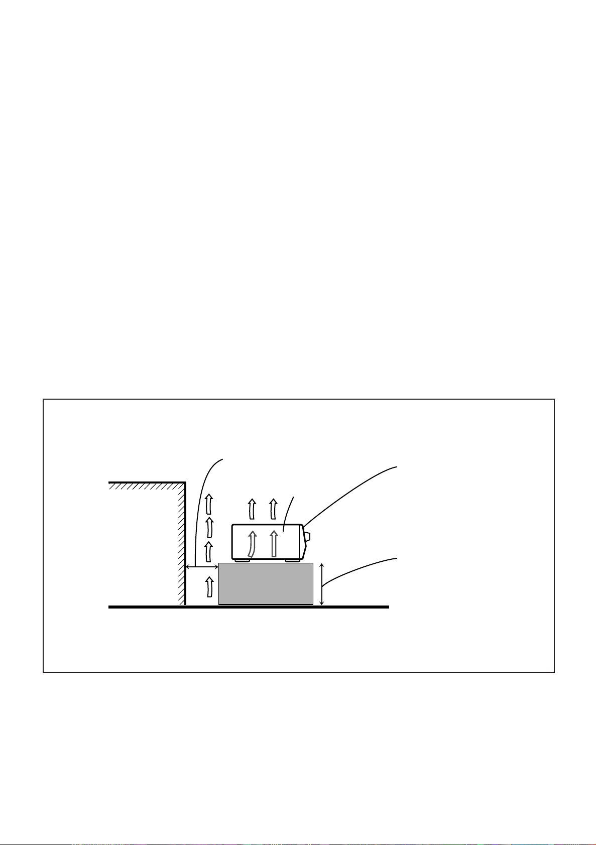
Caution: Proper Ventilation
To avoide risk of electric shock and fire and to protect from damage.
Locate the apparatus as follows:
Front: No obstructions open spacing.
Sides: No obstructions in 10 cm from the sides.
Top: No obstructions in 10 cm from the top.
Back: No obstructions in 15 cm from the back
Bottom: No obstructions, place on the level surface.
In addition, maintain the best possible air circulation as illustrated.
Achtung: Angemessene Ventilation
Stellen Sie das Gerät zur Verhütung von elektrischem Schlag und
Feuer und zum Schutz gegen Beschädigung wie folgt auf:
Vorderseite: Offener Platz ohne Hindernisse.
Seiten: Keine Hindernisse innerhalb 10 cm von den Seiten.
Oberseite: Keine Hindernisse innerhalb 10 cm von der Oberseite.
Rückseite: Keine Hindernisse innerhalb 15 cm von der Rückseite.
Unterseite: Keine Hindernisse. Auf eine ebene Oberfläche stellen.
Zusätzlich die bestmögliche Luftzirkulation wie gezeigt erhalten.
Attention: Ventilation Correcte
Pour éviter les chocs électriques, l’incendie et tout autre dégât.
Disposer l’appareil en tenant compte des impératifs suivants
Avant: Rien ne doit gêner le dégagement
Flancs: Laisser 10 cm de dégagement latéral
Dessus: Laisser 10 cm de dégagement supérieur
Arrière: Laisser 15 cm de dégagement arrière
Dessous: Rien ne doit obstruer par dessous; poser l’appareil sur
une surface plate.
Veiller également à ce que l’air circule le mieux possible comme
illustré.
Voorzichtig: Zorg Voor Goede Ventilatie
Om gevaar voor brand of een elektrische schok te voorkomen, dient u
bij opstelling van het apparaat op de volgende punten te letten:
Voorkant: Voldoende ruimte vrij houden.
Zijkanten: Minstens 10 cm aan weerszijden vrij houden.
Bovenkant: Niets bovenop plaatsen; 10 cm speling geven.
Achterkant: Minstens 15 cm ruimte achteraan vrij houden.
Onderkant: Opstellen op een egaal horizontaal oppervlak.
Bovendien moet er rondom voldoende luchtdoorstroming zijn, zoals in
de afbeelding aangegeven.
Precaución: Ventilación Adecuada
Para evitar el riesgo de choque eléctrico e incendio y para proteger el
aparato contra daños.
Ubique el aparato de la siguiente manera:
Frente: Espacio abierto sin obstrucciones
Lados: 10 cm sin obstrucciones a los lados
Parte superior: 10 cm sin obstrucciones en la parte superior
Parte trasera: 15 cm sin obstrucciones en la parte trasera
Fondo: Sin obstrucciones, colóquelo sobre una superficie
nivelada
Además, mantenga la mejor circulación de aire posible como se
ilustra.
Attenzione: Problemi di Ventilazione
Per evitare il rischio di folgorazioni ed incendi e proteggere l’unità da
danni, installarla nel modo seguente.
Davanti: Nessun ostacolo, spazio libero
Lati: Nessun ostacolo per almeno 10 cm
Sopra: Nessun ostacolo per almeno 10 cm
Retro: Nessun ostacolo per almeno 15 cm
Fondo: Libero ed in piano
Inoltre, mantenere il più possibile la circolazione dell’aria.
Wall or obstructions
Wand oder Hindernisse
Mur, ou obstruction
Wand of meubilair
Pared u obstrucciones
Parete o ostacol
Spacing 15 cm or more
Abstand von 15 cm oder mehr
Dégagement de 15 cm ou plus
Minstens 15 cm tussenruimte
Espacio de 15 cm o más
15 cm di distanza o più
RX-884RBK
Floor
Boden
Plancher
Vloer
Piso
Pavimento
Front
Vorderseite
Avant
Voorkant
Frente
Davanti
Stand height 15 cm or more
Standhöhe 15 cm oder mehr
Hauteur du socle: 15 cm ou plus
Standard op minstens 15 cm van de vloer
Allura del soporte 15 cm o más
Altezza del tavolino 15 cm p plù
G-4
Page 6

Table of Contents
English
Parts Identification ...................................................................................... 3
Getting Started........................................................................................... 4
Before Installation................................................................................................................................................................... 4
Checking the Supplied Accessories ........................................................................................................................................ 4
Connecting the FM and AM (MW/LW) Antennas ................................................................................................................. 5
Connecting the Speakers......................................................................................................................................................... 6
Connecting Audio/Video Components ................................................................................................................................... 9
Connecting the Power Cord .................................................................................................................................................. 13
Putting Batteries in the Remote Control ............................................................................................................................... 13
Basic Operations ....................................................................................... 14
Turning the Power On and Off (Standby) ............................................................................................................................. 14
Selecting the Source to Play .................................................................................................................................................14
Adjusting the Volume............................................................................................................................................................ 15
Selecting the Front Speakers................................................................................................................................................. 16
Muting the Sound.................................................................................................................................................................. 16
Recording a Source ............................................................................................................................................................... 16
Attenuating the Input Signal ................................................................................................................................................. 17
Adjusting the Subwoofer Output Level ................................................................................................................................ 17
Basic Settings........................................................................................... 18
Changing the Source Name ..................................................................................................................................................18
Selecting the Input Mode ...................................................................................................................................................... 18
Adjusting the Front Speaker Output Balance .......................................................................................................................19
Setting the Subwoofer Information....................................................................................................................................... 19
Listening at Low Volume (Loudness) ................................................................................................................................... 19
Digital Input (DIGITAL IN) Terminal Setting...................................................................................................................... 20
Setting the Speakers for the DSP Modes .............................................................................................................................. 20
One Touch Operation .................................................................................. 23
About the One Touch Operation ........................................................................................................................................... 23
Using the One Touch Operation............................................................................................................................................ 23
Receiving Radio Broadcasts ........................................................................ 24
Tuning in Stations Manually................................................................................................................................................. 24
Using Preset Tuning.............................................................................................................................................................. 24
Selecting the FM Reception Mode ....................................................................................................................................... 25
Assigning Names to Preset Stations ..................................................................................................................................... 26
Using the RDS (Radio Data System) to Receive FM Stations ............................................................................................. 27
What Information Can RDS Signals Provide?......................................................................................................................27
Searching for a Program by PTY Codes............................................................................................................................... 28
Switching to a Broadcast Program of Your Choice Temporarily .......................................................................................... 30
1
Page 7

Using the SEA Modes ................................................................................ 32
Selecting Your Favorite SEA Mode ...................................................................................................................................... 32
Creating Your Own SEA Mode............................................................................................................................................. 33
Using the DSP Modes ................................................................................ 34
Using the 3D-PHONIC Modes ............................................................................................................................................. 35
Using the DAP Modes .......................................................................................................................................................... 38
Using the Dolby Digital and Dolby Pro Logic Modes ......................................................................................................... 40
Using the Theater Surround Mode........................................................................................................................................ 43
Using the On-Screen Menus........................................................................ 47
Selecting the Source to Play ................................................................................................................................................. 47
Selecting the Different Sources for Picture and Sound ........................................................................................................ 47
Using the DSP Modes........................................................................................................................................................... 47
Adjusting the Front Speaker Output Balance ....................................................................................................................... 48
Listening at Low Volume (Loudness) ................................................................................................................................... 48
Attenuating the Input Signal ................................................................................................................................................. 48
Adjusting the Subwoofer Output Level ................................................................................................................................ 49
Adjusting the DSP Modes..................................................................................................................................................... 49
Selecting Your Favorite SEA Mode ...................................................................................................................................... 50
Creating Your Own SEA Mode............................................................................................................................................. 51
Basic Settings........................................................................................................................................................................ 51
Operating the Tuner .............................................................................................................................................................. 52
Storing the Preset Stations .................................................................................................................................................... 52
Assigning Names to the Preset Stations ............................................................................................................................... 53
Checking the RDS Information ............................................................................................................................................ 54
English
COMPU LINK Remote Control System ......................................................... 55
TEXT COMPU LINK Remote Control System................................................. 56
Showing the Disc Information on the TV Screen................................................................................................................. 57
Searching a Disc (Only for the CD Player) .......................................................................................................................... 58
Using the User File (Only for the CD Player with the User File Function) ......................................................................... 60
Entering the Disc Information .............................................................................................................................................. 61
Operating JVC’s Audio/Video Components ................................................... 63
Operating Other Manufactures’ Components ............................................... 67
Troubleshooting......................................................................................... 74
Specifications............................................................................................ 75
2
Page 8
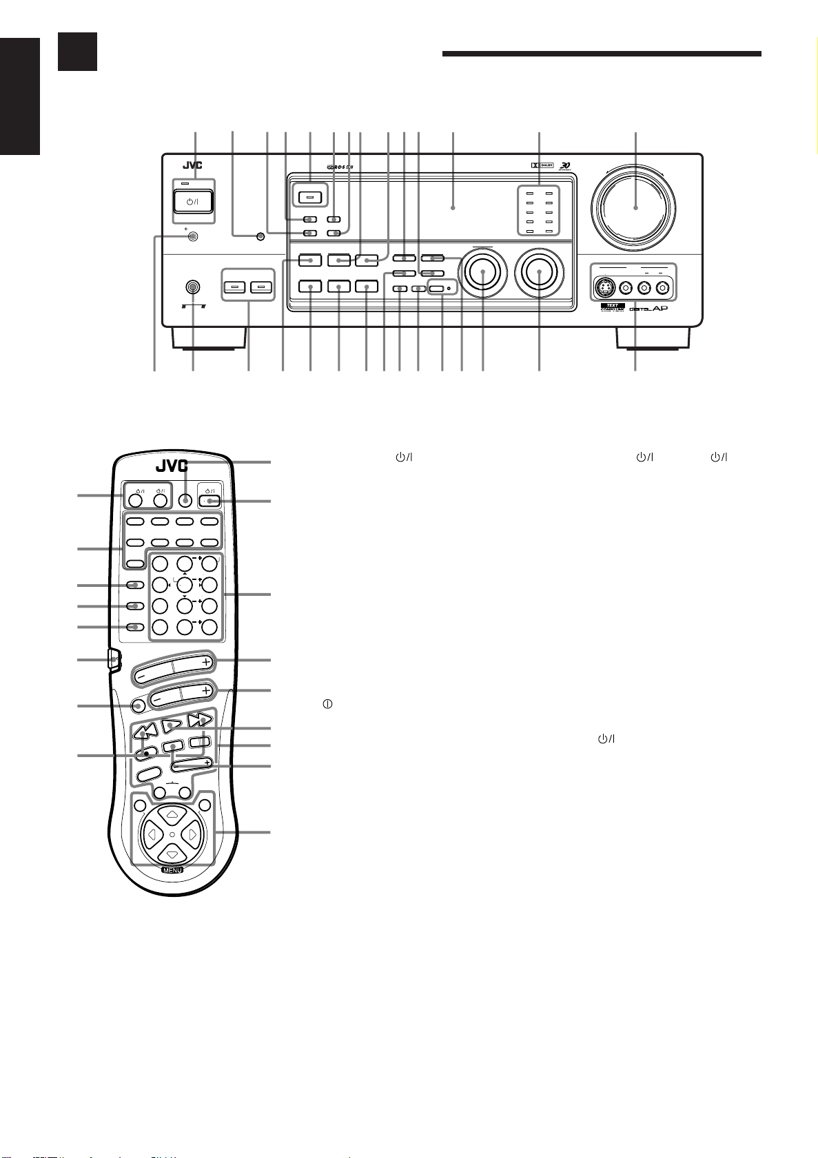
Parts Identification
Become familiar with the buttons and controls on the receiver before use.
English
∞
§
¶
•
ª
º
–
≠
3
@
RM-SR884RU REMOTE CONTROL
VCR1
TAPE/MD FM/AMPHONO
CNTR TONE
TEST
EFFECT
SEA MODE
10
RETURN
PTY SEARCH
PTY –
4 / REW
REC
TV/VIDEO
VCR1 TAPE
SET
O
N
S
C
R
ANALOG
/DIGITAL
ENTER
/P
FM MODE/MUTE
VOLUME
CHANNEL
PLAY
STOP
DISPLAY MODE
CONTROL
E
E
C
N
TV/CATV
/DBS
DVD VCR1 VIDEOVCR2
CD
TV/DBS
SURROUND
MODE
SOUND
CONTROL
CD
DISC
AUDIO/TV
/VCR
CATV
/DBS
MUTE
1234568790- ~=!
RX-884R AUDIO/VIDEO CONTROL RECEIVER
STANDBY
STANDBY/ON
POWER
_ ON — OFF
PHONES
COMPULINK
Remote
SPEAKERS
12
ENHANCED COMPULINK CONTROL SYSTEM
#$
DOLBY SURROUND
EON
TA/NEWS/INFO
PTY SEARCH
DISPLAY MODE
DSP MODE
SEA MODE
DIGITAL INPUT
BALANCE/SURROUND
SEA ADJUST SETTING
ADJUST
%^&*(
TUNER/SEA MEMORY
SOUND SELECT
INPUT ATT.
)_
FM/AM TUNNING TUNER PRESET
FM MODE
LOUDNESS ONE TOUCH OPERATION
SOURCE NAME
DIGITAL
CD
DVD
TV SOUND/DBS PHONO
TAPE/MDVCR 1
FM
VCR 2
VIDEO
AM
MULTI JOG
SOURCE SELECTOR
+¡ ™ £ ¢
MASTER VOLUME
–
S-VIDEO VIDEO AUDIOLR
+
VIDEO
Refer to the pages in parentheses for details.
AUDIO
CNTR
MENU
213
REAR L
546
REAR R
87
9
SUBWOOFER
+10
0
100+
PTY +
FF / ¢
PAUSE
TV VOLUME
EXIT
L
O
R
T
N
O
Front Panel
1
Ÿ
⁄
¤
‹
›
fi
fl
‡
°
STANDBY/ON button and STANDBY
lamp (14)
2
Remote sensor (13)
3
PTY SEARCH button (28)
4
EON button (30)
5
DOLBY SURROUND b utton and lamp (42)
6
TA/NEWS/INFO button (30)
7
DISPLAY MODE button (27)
8
SEA MODE button (32) *
9
DIGITAL INPUT button (18)
0
FM/AM TUNING button (24) *
-
FM MODE button (25)
=
Display (14)
~
Source lamps (14)
!
MASTER VOLUME control (15)
@
#
PHONES jack (16)
$
SPEAKERS 1/2 buttons and lamps (16)
%
DSP MODE button (35) *
^
BALANCE/SURROUND ADJUST b utton
(19, 36) *
&
SEA ADJUST button (33) *
*
SETTING button (19) *
(
TUNER/SEA MEMOR Y button (24, 26, 33)
)
SOUND SELECT/INPUT ATT. button
(15, 17)
_
LOUDNESS/SOURCE NAME button
(18, 19)
+
ONE TOUCH OPERATION button and
lamp (23)
¡
TUNER PRESET button (25) *
™
MULTI JOG control
POWER switch (13)
Remote Control
∞
TV/CATV/DBS and VCR1
buttons (65, 66)
§
Source selecting buttons (15)
¶
SURROUND MODE button (37)
•
SOUND CONTROL button (32, 37, 63)
ª
CD DISC button (64)
º
Remote control mode selector (AUDIO/
TV/VCR, CATV/DBS) (14, 63, 67)
To operate an audio system, TV,
and VCR, set this selector to
“AUDIO/TV/VCR.”
To operate a CATV converter
and DBS tuner, set this selector to
“CATV/DBS.”
–
MUTE button (16)
≠
PTY buttons (+/–) (29)
Ÿ
ANALOG/DIGITAL button (18)
⁄
AUDIO button (14)
¤
10 keys for selecting preset channel (25)
10 keys for adjusting sound (32, 37)
10 keys for operating audio/video
components (63, 67)
‹
VOLUME buttons (+/–) (15)
›
CHANNEL buttons (+/–) (65, 67)
fi
PTY SEARCH button (29)
fl
Operating buttons for audio/video
components (63, 67)
‡
DISPLAY MODE button (27)
°
MENU operating buttons (SET, EXIT, %,
fi, @, #) (47)
What this control actually does
depends on which function you are
trying to adjust. Before using this
control, select the function by
pressing one of the buttons marked
with *.
£
SOURCE SELECTOR control (14)
¢
VIDEO input jacks (11)
Page 9

Getting Started
This section explains how to connect audio/video components and speakers to the receiver, and how to
connect the power supply.
Before Installation
General
• Be sure your hands are dry.
• Turn the power off to all components.
• Read the manuals supplied with the components you are going to connect.
Locations
• Install the receiver in a location that is level and protected from moisture.
• The temperature around the receiver must be between –5˚ and 35˚ C (23˚ and 95˚ F).
• Make sure there is good ventilation around the receiver. Poor ventilation could cause
overheating and damage the receiver.
Handling the receiver
• Do not insert any metal object into the receiver.
• Do not disassemble the receiver or remove screws, covers, or cabinet.
• Do not expose the receiver to rain or moisture.
English
Checking the Supplied Accessories
Check to be sure you have all of the following items, which are supplied with the
receiver.
The number in the parentheses indicates quantity of the pieces supplied.
• Remote Control (1)
• Batteries (2)
• AM (MW/LW) Loop Antenna (1)
• FM Antenna (1)
If anything is missing, contact your dealer immediately.
4
Page 10
Getting Started
English
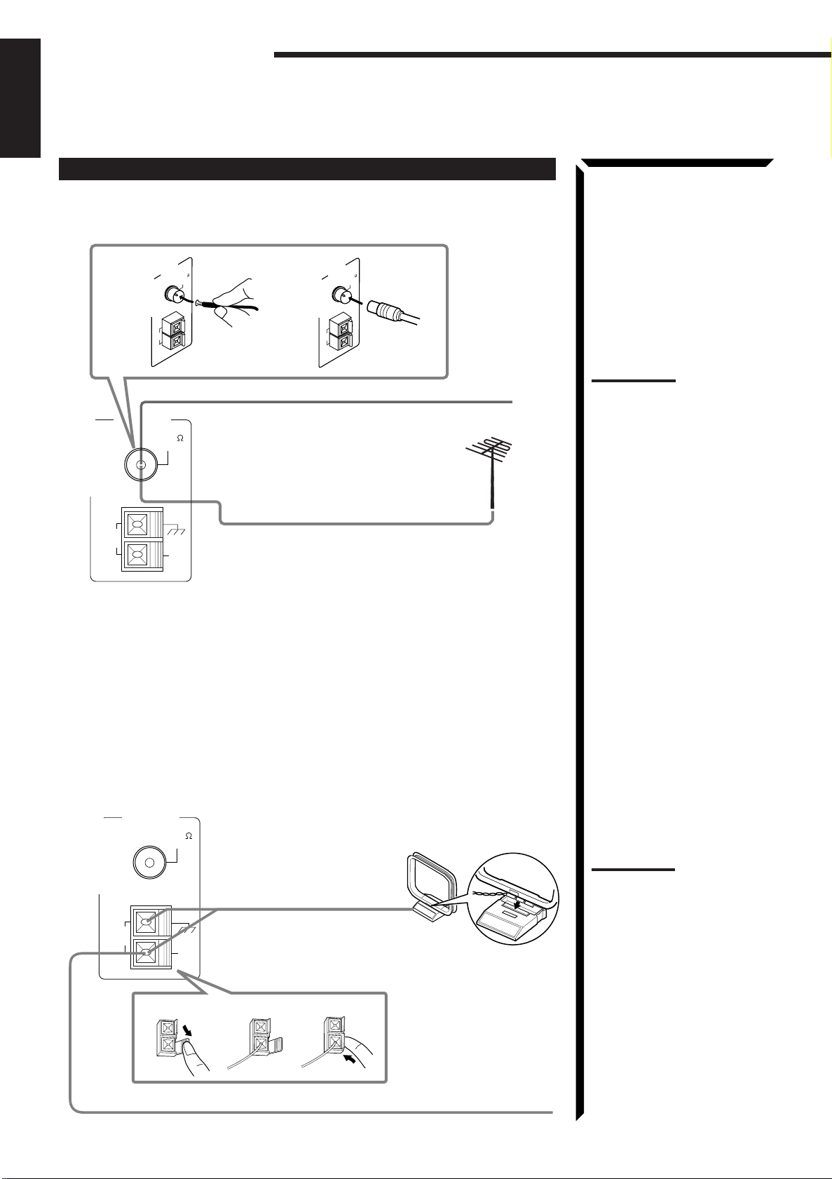
Connecting the FM and AM (MW/LW) Antennas
FM Antenna Connections
A
AM
LOOP
ANTENNA
FM 75
COAXIAL
GND
AM
EXT
B
AM
LOOP
ANTENNA
FM 75
COAXIAL
GND
AM
EXT
FM Antenna
ANTENNA
AM
LOOP
FM 75
COAXIAL
Extend the FM wire antenna horizontally.
GND
AM
EXT
Outside FM Antenna Cable
A. Using the Supplied FM Antenna
The FM antenna provided can be connected to the FM 75Ω COAXIAL terminal as
temporary measure.
B. Using the Standard Type Connector (Not Supplied)
A standard type connector (IEC or DIN45325) should be connected to the FM 75Ω
COAXIAL terminal.
Note:
If reception is poor, connect the
outside antenna.
Before attaching a 75Ω coaxial
cable (the kind with a round wire
going to an outside antenna),
disconnect the supplied FM wire
antenna.
AM (MW/LW) Antenna Connections
ANTENNA
FM 75
COAXIAL
AM (MW/LW) Loop Antenna
GND
AM
LOOP
AM
EXT
1
2
3
5
Turn the loop until you
have the best reception.
Snap the tabs on the loop
into the slots of the base to
assemble the AM (MW/
LW) loop.
Outdoor single vinylcovered wire
Notes:
• Make sure the antenna
conductors do not touch any
other terminals, connecting
cords and power cord. This
could cause poor reception.
• If reception is poor, connect
an outdoor single vinylcovered wire to the AM EXT
terminal. (Keep the AM (MW/
LW) loop antenna connected.)
Page 11
Connecting the Speakers
RIGHT
1
English
You can connect the following speakers:
• Two pairs of front speakers to produce normal stereo sound.
• One pair of rear speakers to enjoy the surround effect.
• One center speaker to produce more effective surround effect (to emphasize human
voices).
CAUTION:
Use speakers with the
SPEAKER IMPEDANCE
indicated by the speaker
terminals.
• One subwoofer to enhance the bass.
IMPORTANT:
After connecting the speakers listed above, set the speaker setting information
properly to obtain the best possible performance. For details, see pages 19 and 20.
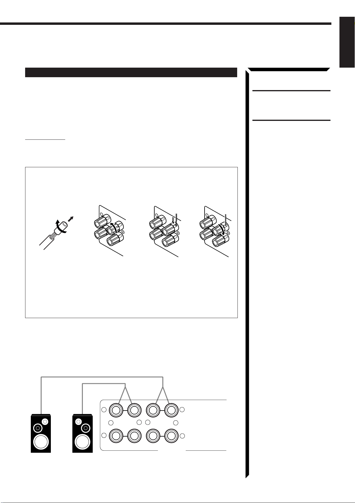
For each speaker (except for subwoofer), connect the (–) and (+) terminals on the
rear panel to the (–) and (+) terminals marked on the speakers. For connecting a
subwoofer, see page 7.
134
2
1
RIGHT
1
RIGHT
1 Cut, twist and remove the insulation at the end of each speaker signal cable.
2 Turn the knob counterclockwise.
3 Insert the speaker signal cable.
4 Turn the knob clockwise.
Connecting the front speakers
Connect the front speakers to the FRONT SPEAKERS terminals.
You can connect two pairs of front speakers (one pair to the FRONT SPEAKERS 1
terminals, and another pair to the FRONT SPEAKERS 2 terminals).
1
+
2
Right SpeakerLeft Speaker
–+–
RIGHT LEFT
FRONT SPEAKERS
1
2
6
Page 12
Getting Started
English
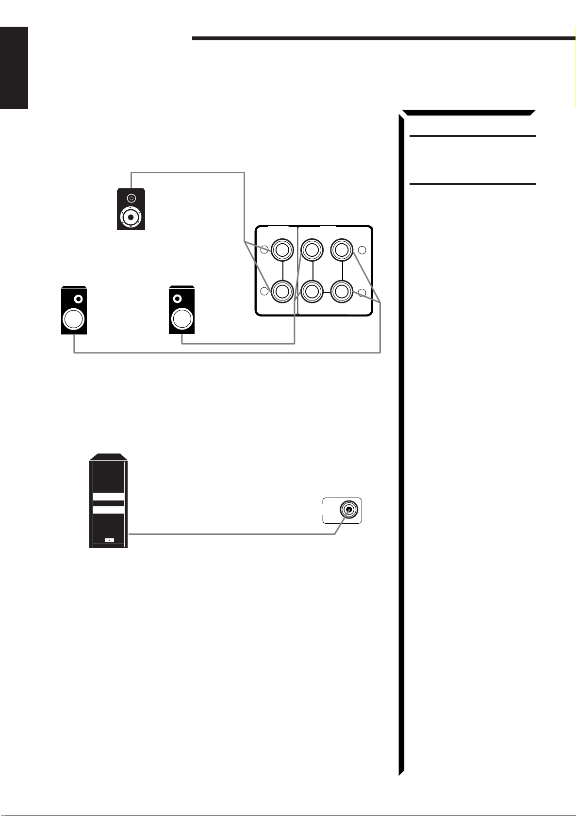
Connecting the rear and center speakers
Connect the rear speakers to the REAR SPEAKERS terminals and a center speaker to
the CENTER SPEAKER terminals.
CAUTION:
Use speakers with the
SPEAKER IMPEDANCE
indicated by the speaker
terminals.
SPEAKERS
RIGHT
REAR
+
–
LEFT
Left rear speaker
Center speaker
Right rear speaker
CENTER
SPEAKER
+
–
Connecting the subwoofer speaker
Connect the input jack of a powered subwoofer to the SUBWOOFER OUT jack on the
rear panel, using a cable with RCA pin plugs.
SUBWOOFER
OUT
Powered subwoofer
7
Page 13
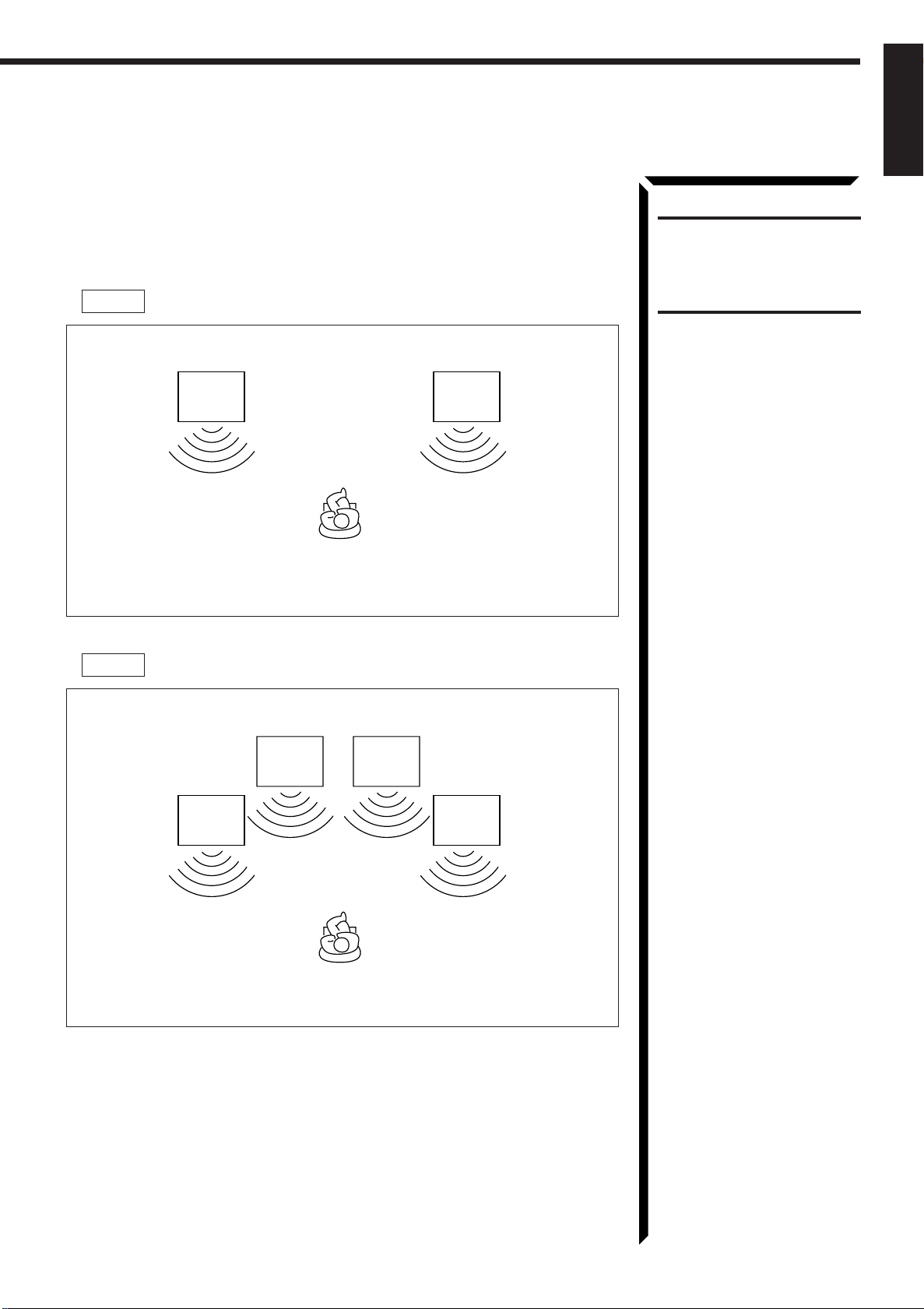
About the speaker impedance
The required speaker impedance of the front speakers does differ depending on whether
both the FRONT SPEAKERS 1 and FRONT SPEAKERS 2 terminals are used or
only one of them is used.
CASE 1 When you connect only one set of front speakers
English
CAUTION:
When connecting speakers, use
speakers with the same
SPEAKER IMPEDANCE
indicated by the speaker
terminals.
Front
Speaker
1
Speaker
Use front speakers with 4 — 16 ohm impedance.
CASE 2 When you connect two sets of front speakers
Front
Speaker
2
Front
Speaker
1
Front
Speaker
2
Speaker
Front
1
Front
1
Use front speakers with 8 — 16 ohm impedance.
8
Page 14
Getting Started
English
Connecting Audio/Video Components
You can connect the following audio/video components to this receiver. Refer also to the
manuals supplied with your components. If you want to connect a component not listed
in the table below, refer to the manual supplied with it.
Audio Components Video Components
• Turntable • DVD player*
• CD player* • TV
• Cassette deck or MD recorder* • DBS tuner*
• VCRs
• Video camera
* You can connect these components using the methods described in “Analog
connections” (below) or in “Digital connections” (see page 12).
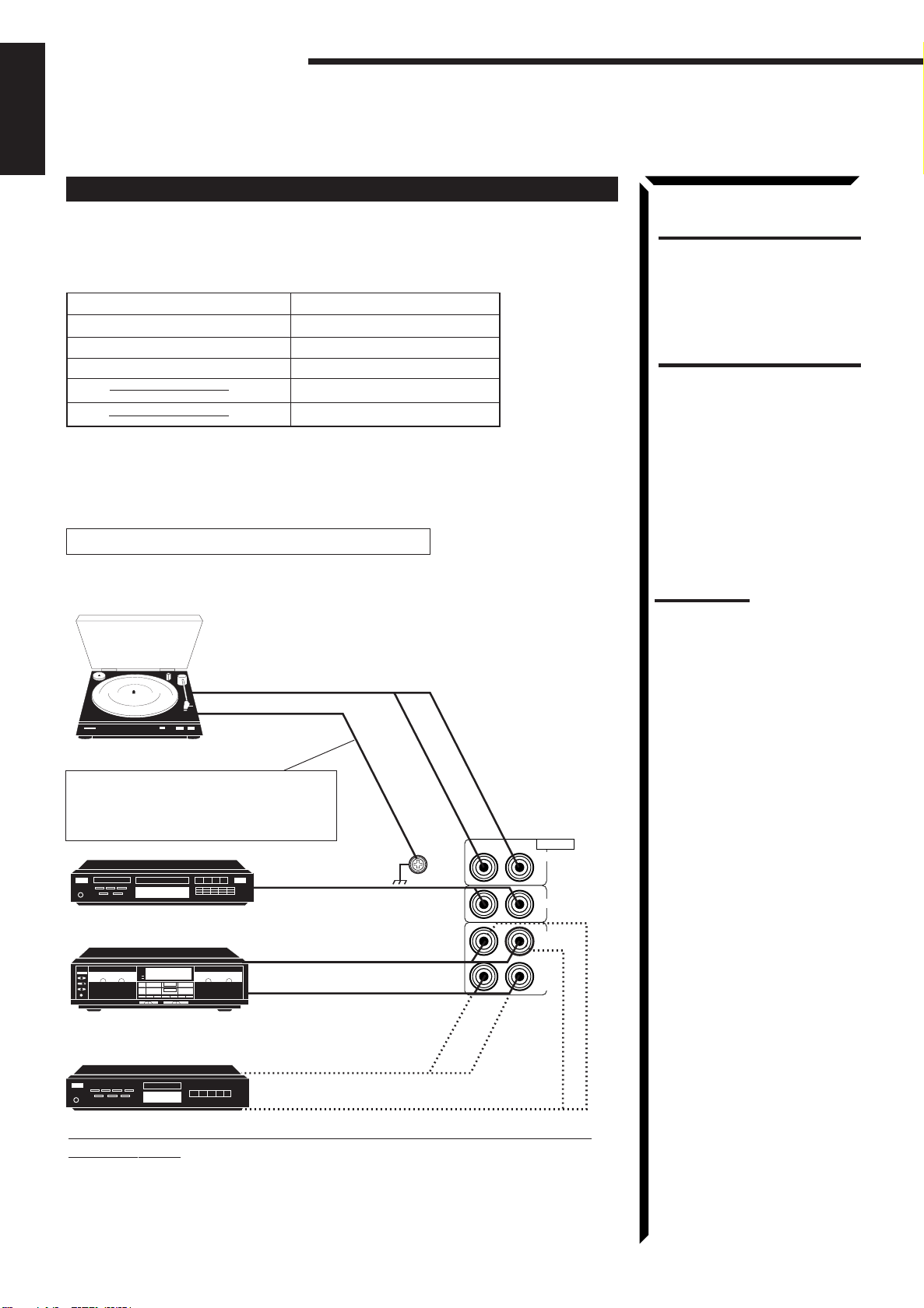
Analog connections
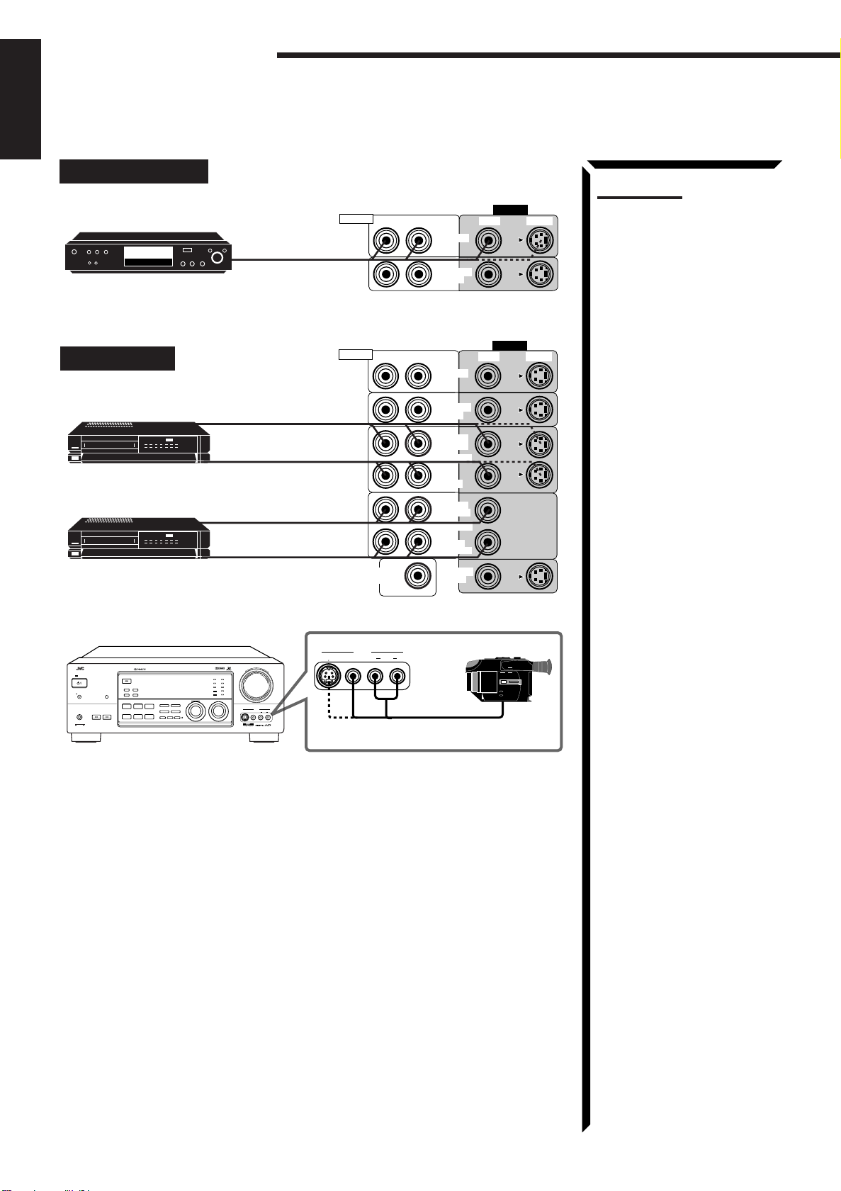
Audio component connections
Use the cables with RCA pin plugs (not supplied).
Connect the white plug to the audio left jack, and the red plug to the audio right jack.
To audio output
Turntable
If an earth cable is provided for your
turntable, connect the cable to the
screw marked GND on the rear panel.
AUDIO
PHONO
CD
OUT
(REC)
TAPE
/MD
IN
(PLAY)
CD player
Cassette deck
or
MD recorder
To audio output
To audio input
To audio output
To audio output
GND
RIGHT LEFT
CAUTION:
If you connect a soundenhancing device such as a
graphic equalizer between the
source components and this
receiver, the sound output
through this receiver may be
distorted.
Notes:
• Any turntables incorporating
a small-output cartridge such
as an MC (moving-coil type)
must be connected to this
receiver through a
commercial head amplifier or
step-up transformer. Direct
connection may result in
insufficient volume.
• You can connect either a
cassette deck or an MD
recorder to the T APE/MD
jacks. When connecting an
MD recorder to the T APE/MD
jacks, change the source
name, which will be shown on
the display when selected as
the source, to “MD.” See page
18 for details.
To audio input
If your audio components have a COMPU LINK-3 or TEXT COMPU
LINK terminal
• See also page 55 for detailed information about the connection and the COMPU
LINK-3 remote control system.
• See also page 56 for detailed information about the connection and the TEXT
COMPU LINK remote control system.
9
Page 15
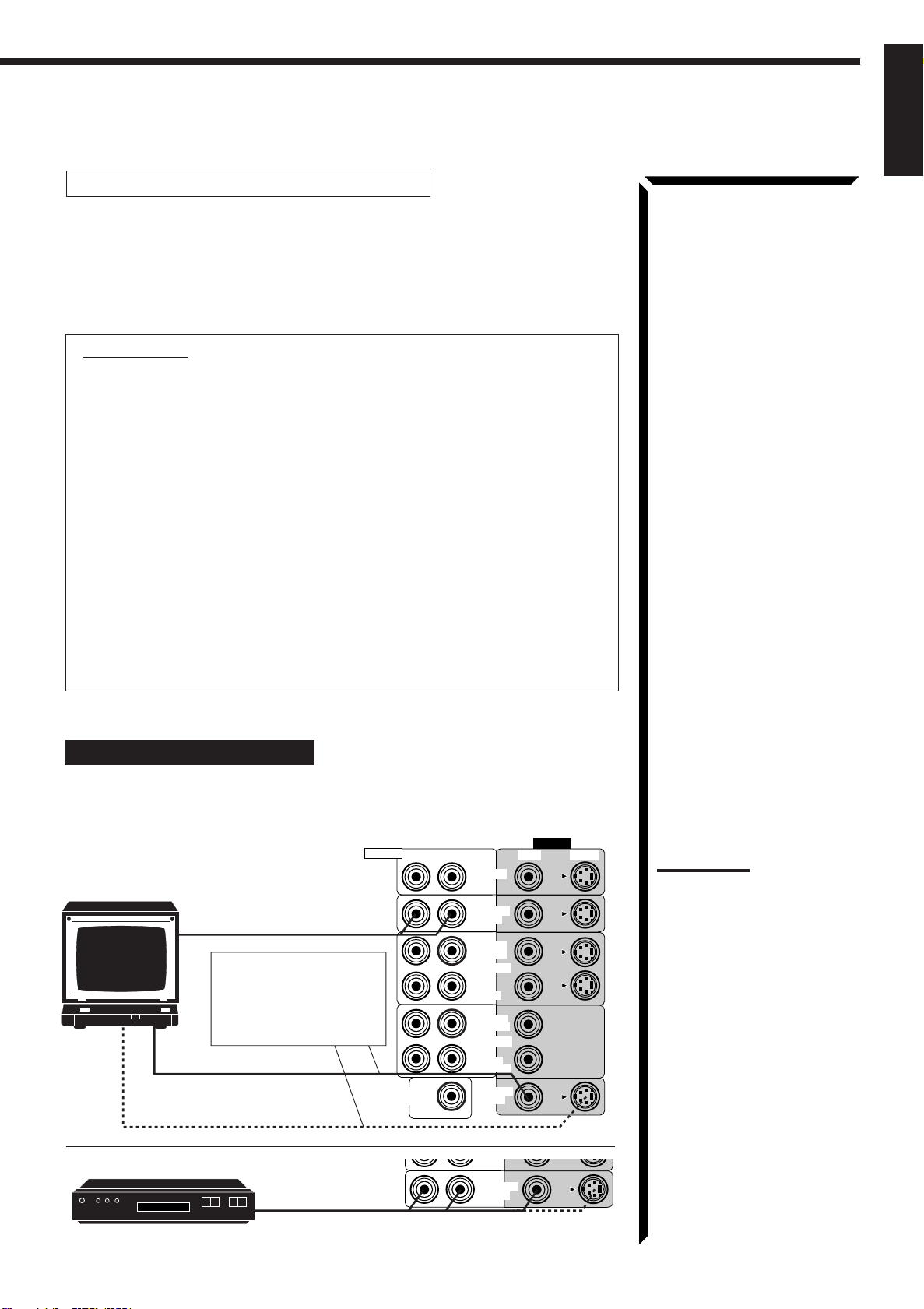
Video component connections
Use the cables with RCA pin plugs (not supplied).
Connect the white plug to the audio left jack, the red plug to the audio right jack, and
the yellow plug to the video jack.
If your video components have S-video (Y/C-separation) terminals, connect them using
S-video cables (not supplied). Connecting these video components through the S-video
input/output terminals will give you better picture playback (or recording) quality.
IMPORTANT:
This receiver is equipped with both the composite video and S-video input/output
terminals for connecting video components.
You do not have to connect both the composite video and S-video terminals.
However, remember that the video signals from the composite video input
terminals are output only through the composite video output terminals,
while the ones from the S-video input terminals are output only through the
S-video output terminals.
Therefore, if a recording video component and a playing video component are
connected to the receiver through the different video terminals, you cannot record
the picture from the playing component on the recording component. In addition,
if the TV and a playing video component are connected to the receiver through the
different video terminals, you cannot view the playback picture from the playing
component on the TV.
English
To view and record the playback picture from the video component connected
to the VCR2 jacks, you must connect the TV and the recording video
component through the composite video terminals.
Connecting the TV and/or DBS tuner
You can connect either the TV or DBS tuner to the TV SOUND/DBS jacks.
VIDEO
VIDEO S-VIDEORIGHT LEFT
IN
TV
To audio output
To composite video input
To S-video input
DBS tuner
DBS
Connect the TV to the
MONITOR OUT jack to
view the playback picture
from the other connected
video components.
To audio/video output
RIGHT
AUDIO
SUBWOOFER
OUT
DVD
TV SOUND
/DBS
OUT
(REC)
VCR 1
IN
(PLAY)
OUT
(REC)
VCR 2
(PLAY)
MONITOR
OUT
TV SOUND
/DBS
Notes:
• Use the video components of
the PAL color system.
• When connecting the TV to
the TV SOUND/DBS jacks,
DO NOT connect the TV’s
video output to these video
input terminals.
• When connecting the DBS
tuner to the TV SOUND/DBS
jacks, change the source
name, which will be shown on
the display when selected as
the source, to “DBS.” See
page 18 for details.
• To enjoy Dolby Digital with the
DBS tuner as the source,
connect the DBS tuner using
the method described in
“Digital connections” on page
12.
10
Page 16
Getting Started
English
Connecting DVD player
DVD player
DVD
To audio/video
output
RIGHT
AUDIO
DVD
TV SOUND
/DBS
Note:
VIDEO
VIDEO S-VIDEORIGHT LEFT
To enjoy Dolby Digital with the
DVD player as the source,
connect the DVD player, using
the method described in “Digital
connections” on page 12.
Connecting VCRs
S-VHS (or VHS) VCR
S-VHS
VHS VCR
VHS
RX-884R AUDIO/VIDEO CONTROL RECEIVER
STANDBY
STANDBY/ON
POWER
_ ON — OFF
PHONES
COMPULINK
Remote
SPEAKERS
12
ENHANCED COMPULINK CONTROL SYSTEM
BALANCE/SURROUND
DOLBY SURROUND
EON
TA/NEWS/INFO
PTY SEARCH
DISPLAY MODE
DSP MODE
SEA MODE
DIGITAL INPUT
FM/AM TUNNING TUNER PRESET
TUNER/SEA MEMORY FM MODE
SEA ADJUST SETTING
ADJUST
SOUND SELECT
LOUDNESS ONE TOUCH OPERATION
SOURCE NAME
INPUT ATT.
To audio/video input
To audio/video output
To audio/video input
To audio/video output
MASTER VOLUME
DIGITAL
–
VIDEO
S-VIDEO VIDEO AUDIOLR
+
DVD
CD
TV SOUND/DBS PHONO
TAPE/MDVCR 1
FM
VCR 2
AM
VIDEO
MULTI JOG
SOURCE SELECTOR
RIGHT
AUDIO
SUBWOOFER
OUT
VIDEO
S-VIDEO VIDEO AUDIOLR
To audio/video output
VIDEO S-VIDEORIGHT LEFT
DVD
TV SOUND
/DBS
OUT
(REC)
VCR 1
IN
(PLAY)
OUT
(REC)
VCR 2
IN
(PLAY)
MONITOR
OUT
Video camera
VIDEO
11
Page 17
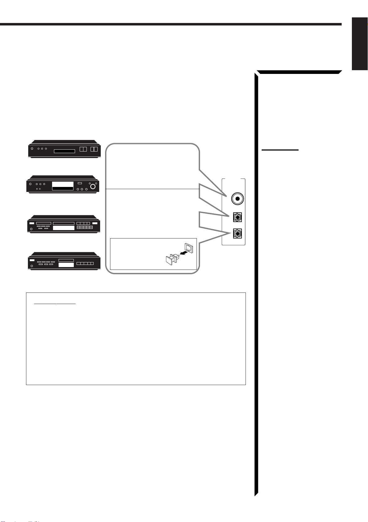
Digital connections
This receiver is equipped with three DIGITAL IN terminals — one digital coaxial
terminal and two digital optical terminals.
To enjoy Dolby Digital, you have to connect the source components using the DIGITAL
IN terminals.
You can connect any component to any one of the digital terminals using the digital
coaxial cable (not supplied) or digital optical cable (not supplied).
DBS tuner
DBS
DVD player
DVD
CD player
MD recorder
When the component has a digital
coaxial output terminal, connect it
to the DIGITAL 1 (DBS) terminal,
using the digital coaxial cable (not
supplied).
When the component has a digital
optical output terminal, connect it
to the DIGITAL 2 (DVD) or
DIGITAL 3 (CD) terminal, using
the digital optical cable (not
supplied).
Before connecting a
digital optical cable,
unplug the protective
plug.
DIGITAL IN
PCM/DOLBY DIGITAL
DIGITAL 1 (DBS)
DIGITAL 2 (DVD)
DIGITAL 3 (CD)
English
Notes:
• When shipped from the
factory, the DIGITAL IN
terminals has been set for use
with the following
components.
– DIGITAL 1 (coaxial): For
DBS tuner
– DIGITAL 2 (optical): For
DVD player
– DIGITAL 3 (optical): For CD
player
• When you want to operate the
CD player or MD recorder
using the COMPU LINK
remote control system,
connect the target component
also as described in “Analog
connections” (see page 9).
IMPORTANT:
• When connecting the DVD player or the DBS tuner using the digital terminal,
you also need to connect it to the video jack (either composite video terminal
or S-video terminal) on the rear. Without connecting it to the video jack, you
can view no playback picture.
• After connecting the above components using the DIGITAL IN terminals, set
the following correctly if necessary.
– Select the digital input mode correctly. For details, see “Selecting the Input
Mode” on page 18.
– Set the digital input (DIGITAL IN) terminal setting correctly. For details,
see “Digital Input (DIGITAL IN) Terminal Setting” on page 20.
12
Page 18
POWER
_ ON — OFF
Getting Started
English
Connecting the Power Cord
Before plugging the receiver into an AC outlet, make sure that all connections have been
made.
1. Plug the power cord into an AC outlet.
2. Press POWER to set it in the _ON position.
The STANDBY lamp lights up. A small amount of power
is always consumed.
To shut off the power completely
Press POWER to set it in the —OFF position.
Keep the power cord away from the connecting cables and the antenna. The power cord
may cause noise or screen interference. We recommend that you use a coaxial cable to
connect the antenna, since it is well-shielded against interference.
The difference between the POWER switch and the
STANDBY/ON
• The POWER switch is the mains supply switch, allowing the receiver to
connect to the mains supply. To shut off the power completely, press the
POWER switch to set it in the —OFF position.
• The STANDBY/ON button is a functional on/off (standby) switch, and
does not disconnect the receiver from the mains supply. A small amount of
power is consumed even in standby mode for the receiver to accept signals from
the remote control.
button
Note:
The preset settings such as
preset channel and sound
adjustment may be erased in
the following cases:
– When you press
to set it in the
– When you unplug the power
cord.
– When a power failure occurs.
CAUTIONS:
• Do not touch the power cord
with wet hands.
• Do not pull on the power cord
to unplug the cord. When
unplugging the cord, always
grasp the plug so as not to
damage the cord.
POWER
—
OFF position.
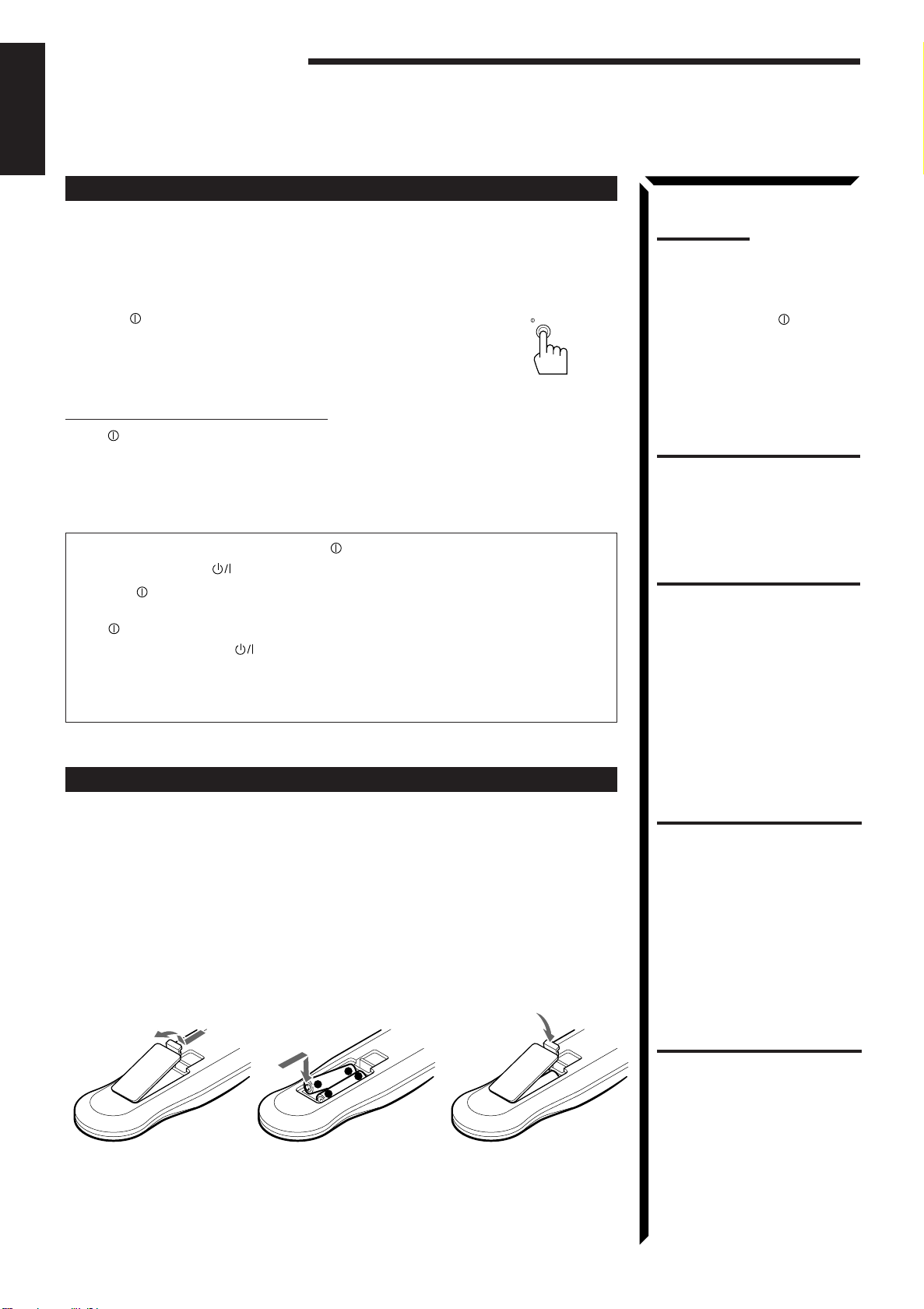
Putting Batteries in the Remote Control
Before using the remote control, put two supplied batteries first. When using the remote
control, aim the remote control directly at the remote sensor on the receiver.
1. On the back of the remote control, remove the battery cover as illustrated.
2. Insert batteries. Make sure to observe the proper polarity: (+) to (+) and (–) to
(–).
3. Replace the cover.
R03 (UM-4)/AAA (24F)
-
+
+
-
If the range or effectiveness of the remote control decreases, replace the batteries. Use
two R03 (UM-4)/AAA (24F) type dry-cell batteries.
CAUTION:
Follow these precautions to
avoid leaking or cracking cells:
• Place batteries in the remote
control so they match the
polarity indicated: (+) to (+)
and (–) to (–).
• Use the correct type of
batteries. Batteries that look
similar may differ in voltage.
• Always replace both batteries
at the same time.
• Do not expose batteries to
heat or flame.
13
Page 19
Basic Operations
SOURCE SELECTOR
STANDBY
STANDBY/ON
STANDBY
STANDBY/ON
The following operations are commonly used when you play any sound source.
IMPORTANT:
When using the Remote Control, check to see if its remote control
AUDIO/TV
mode selector is set to the correct position:
/VCR
To operate an audio system, TV, and VCR, set it to “AUDIO/TV/
CATV
/DBS
VCR.”
To operate a CATV converter and DBS tuner, set it to “CATV/
DBS.”
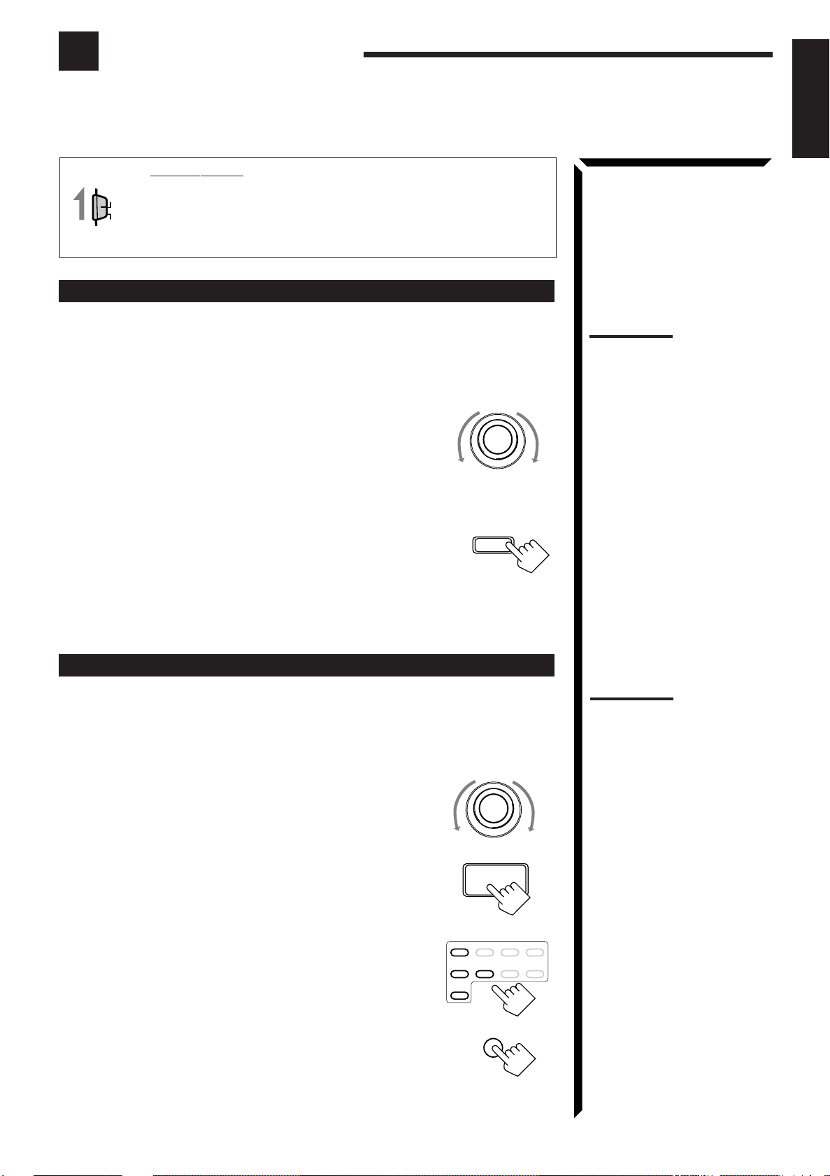
Turning the Power On and Off (Standby)
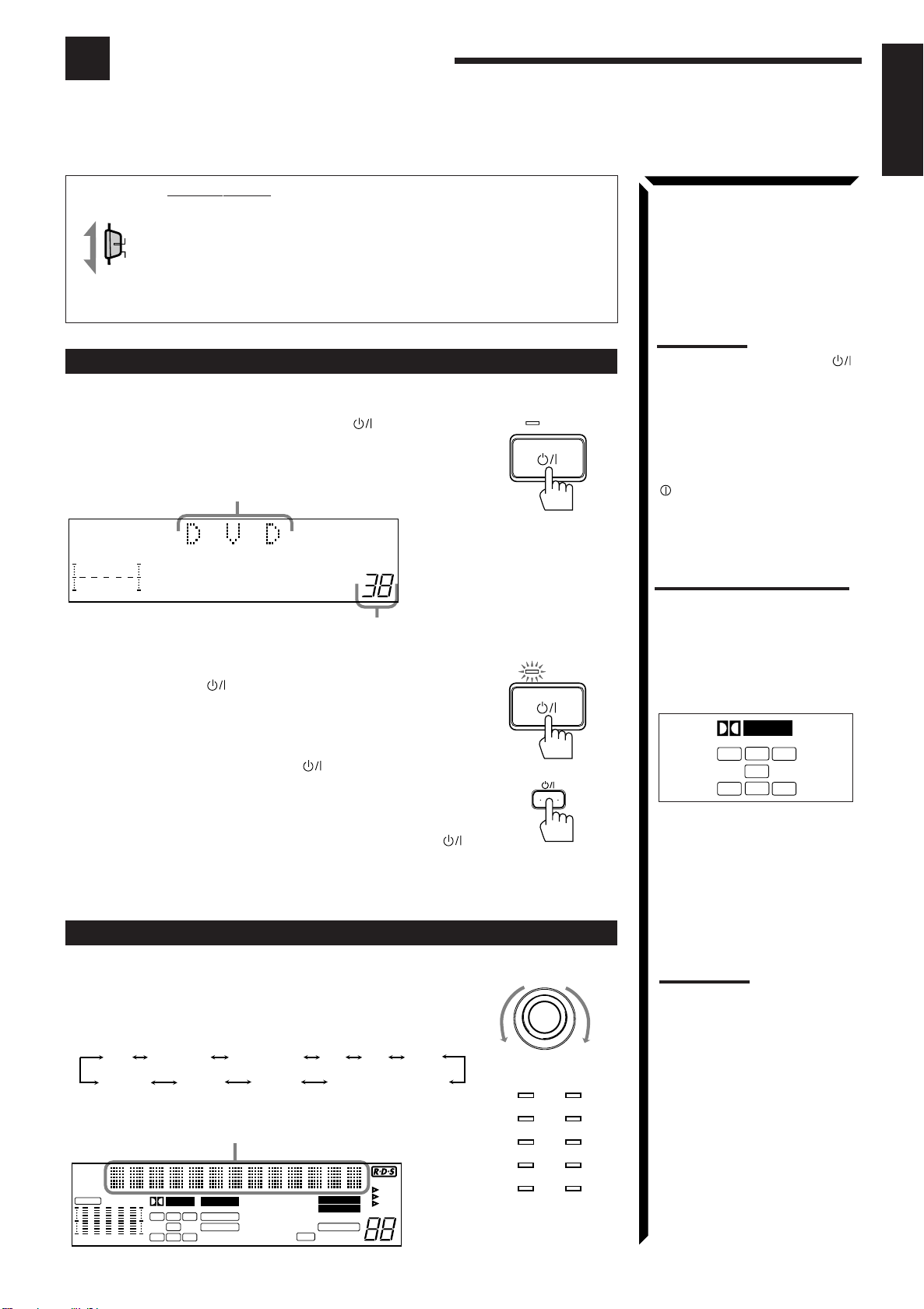
On the front panel:
To turn on the power, press STANDBY/ON .
The STANDBY lamp goes off. The name of the current source (or
station frequency) appears on the display.
Current source name appears
Note:
Pressing the STANDBY/ON
button again turns off the power
(into standby mode) and lights
the STANDBY lamp. A small
amount of power is consumed
in standby mode. To turn the
power off completely, press the
POWER switch to set it in the
—
OFF position on the front
panel.
English
VOLUME
100 1k 10k
Current volume level
is shown here
To turn off the power (into standby mode),
press STANDBY/ON again.
The STANDBY lamp lights up.
From the remote control:
To turn on the power, press AUDIO .
The STANDBY lamp goes off. The name of the current source (or
station frequency) appears on the display.
To turn off the power (into standby mode), press AUDIO
again.
The STANDBY lamp lights up.
Selecting the Source to Play
On the front panel:
Turn SOURCE SELECTOR until the source name you want
appears on the display.
As you turn the selector, the source changes as follows:
PHONOCD TAPE/MD AM DVD
VIDEO
The selected source lamp also lights up.
Selected source name appears
CH–
CNTR
S E A
FR
100 1k 10k
DIGITAL
L
LS
PRO LOGIC
C
R
D S P
LFE
3D-PHONC
S
RS
OVER LEVEL
VCR1VCR2
THEATER DRAMA
LIVE CLUB ACTION
DANCE CLUB
HALL HEADPHONE
PA VILION
FM
TV SOUND/DBS
TUNED
STEREO
VOLUME
ATT
MUTE AUTO
LOUDNESS
EON
TA
NEWS
INFO
AUDIO
DVD
TV SOUND/DBS PHONO
VCR 2
VIDEO
CD
TAPE/MDVCR 1
FM
AM
Source lamps on the
front panel
What are the following
indicators?
When you select the source
encoded with Dolby Digital and
start playback, the following
indicators light up on the display
to show the signal being input to
this receiver. (Only the indicators
for the received signals light up.)
DIGITAL
C
L
LS
LFE
S
R
RS
L: Left front channel
R: Right front channel
C: Center channel
LS: Left rear channel
RS: Right rear channel
S: Rear channel (monaural)
LFE: Subwoofer channel
Note:
When connecting an MD
recorder (to the TAPE/MD
jacks), and a DBS tuner (to the
TV SOUND/DBS jacks), change
the source name appears on
the display. For details, see
page 18.
14
Page 20
Basic Operations
SOURCE SELECTOR
English
From the remote control:
Press one of the source selecting buttons directly.
DVD Selects the DVD player.
VCR1 Selects the video component connected to the VCR1
jacks.
VCR2 Selects the video component connected to the VCR2
jacks.
VIDEO Selects the video component connected to the
VIDEO jacks.
CD* Selects the CD player.
TAPE/MD* Selects the cassette deck or the MD recorder.
PHONO* Selects the turntable.
FM/AM* Selects an FM and AM (MW/LW) broadcast.
Each time you press the button, the band alternates
between FM and AM (MW/LW).
TV/DBS • Selects TV sounds when the remote control selector is set to “AUDIO/
TV/VCR.”
• Selects the DBS tuner when the remote control selector is set to
“CATV/DBS.”
DVD VCR1 VIDEOVCR2
CD
TV/DBS
TAPE/MD FM/AMPHONO
Note:
When you press one of the
source selecting buttons
marked above with an asterisk
(*), the receiver automatically
turns on.
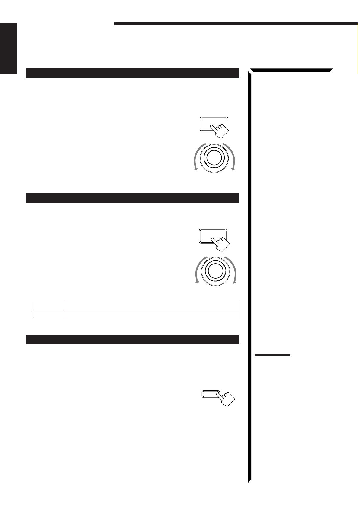
Selecting different sources for picture and sound
You can watch picture from a video component while listening to sound from another
component.
On the front panel:
1. Press SOUND SELECT briefly while viewing the picture
from a video component such as the VCR or DVD player,
etc.
“SOUND SELECT” appears on the display.
2. Turn SOURCE SELECTOR to select the sound (except the
TV sound), while the indication of the above step is still on
the display.
SOUND SELECT
INPUT ATT.
From the remote control:
Press one of the audio source selecting buttons (CD, TAPE/MD, PHONO, FM/AM),
while viewing the picture from a video component such as the VCR or DVD player, etc.
Adjusting the Volume
On the front panel:
To increase the volume, turn MASTER VOLUME clockwise.
To decrease the volume, turn it counterclockwise.
When you turn MASTER VOLUME rapidly, the volume
level also changes rapidly.
When you turn MASTER VOLUME slowly, the volume
level also changes slowly.
–
MASTER VOLUME
+
Notes:
• Once you have selected a
video source, pictures of the
selected source is sent to the
TV until you select another
video source.
• When you select TV sound as
the source, this function does
not work.
CAUTION:
Always set the volume to the
minimum before starting any
source. If the volume is set at its
high level, the sudden blast of
sound energy can permanently
damage your hearing and/or
ruin your speakers.
From the remote control:
To increase the volume, press VOLUME +.
To decrease the volume, press VOLUME –.
15
–
VOLUME
+
Note:
The volume level can be
adjusted within the range of “0”
(minimum) to “90” (maximum).
Page 21
Selecting the Front Speakers
MUTE
English
On the front panel
When you have connected two pairs of the front speakers, you can
only
:
SPEAKERS
12
select which to use.
Press SPEAKERS 1 or SPEAKERS 2 to select the speaker to
use.
Each time you press the button, the lamp on the respective button turns on and off.
When the lamp on either button lights up, the respective speakers are activated.
IMPORTANT:
You can activate two pairs of the front speakers at the same time only when no
signals are sent to the center and rear speakers. Otherwise, activating one pair of
the speakers deactivates the other.
Listening only with headphones
1. Connect a pair of headphones to the PHONES jack on the front panel.
2. Press SPEAKERS 1 and/or 2 so that no lamps on the buttons are turned on.
Muting the Sound
From the remote control
only
:
Press MUTE to mute the sound through all speakers
and headphones connected.
“MUTE” appears on the display and the volume turns off (the
volume level indicator also goes off).
Note:
If you use any of the DSP
modes other than the 3DPHONIC modes and
“HEADPHONE” with both front
speakers activated, the
speakers connected to the
FRONT SPEAKERS
terminals are deactivated.
CAUTION:
Be sure to turn down the volume
before connecting or putting on
headphones, as high volume
can damage both the
headphones and your hearing.
2
Note:
You cannot shut off the sound
through the subwoofer using the
SPEAKERS 1 and 2 buttons.
To restore the sound, press MUTE again so that “OFF” appears on the display.
Turning MASTER VOLUME or pressing VOLUME +/– also restores the sound at the
previous volume level.
Recording a Source
You can record any source playing through the receiver to the cassette deck or the MD
recorder connected to the TAPE/MD jacks and the VCRs connected to the VCR1 and
VCR2 jacks at the same time.
While recording, you can listen to the selected sound source at whatever sound level
you like, without affecting the sound levels of the recording.
Note:
The output volume level and
SEA modes cannot affect the
recording.
IMPORTANT:
When recording the digital
source, turn off the DSP mode.
16
Page 22
Basic Operations
SOUND
CONTROL
English
Attenuating the Input Signal
When the input level of the playing source through the analog terminals is too high, the
sounds will be distorted. If this happens, you need to attenuate the input signal level to
prevent the sound distortion.
On the front panel
Press and hold SOUND SELECT/INPUT ATT. until “INPUT
only
:
SOUND SELECT
ATT ON” appears on the display.
The ATT indicator also lights up on the display.
INPUT ATT.
Each time you press and hold the button, the input attenuator mode
turns on (“INPUT ATT ON”) and off (“INPUT NORMAL”).
You can set input attenuator mode separately for each source.
Adjusting the Subwoofer Output Level
You can adjust the subwoofer output level if you have selected “YES” for the
“SUBWOOFER” (see page 19).
Once it has been adjusted, the receiver memorizes the adjustment.
On the front panel:
1. Press BALANCE/SURROUND ADJUST repeatedly until
“SUBWFR LEVEL” appears on the display.
The display changes to show the current setting.
BALANCE/SURROUND
ADJUST
Notes:
• This function is available only
for the sources connected
using the analog terminals.
• This function takes effect only
when the DSP mode is in use.
2. Turn MULTI JOG to adjust the subwoofer output level (–
10 dB to +10 dB), while the indication of the previous step is
still on the display.
From the remote control:
1. Press SOUND CONTROL.
10 keys are activated for sound adjustments.
2. Press SUBWOOFER +/– to adjust the subwoofer output
level (–10 dB to +10 dB).
MULTI JOG
SUBWOOFER
0
FM MODE/MUTE
+10
100+
17
Page 23
Basic Settings
SOURCE SELECTOR
DIGITAL INPUT
Some of the following settings are required after connecting and positioning your speakers in your listening
room, while others will make operations easier.
IMPORTANT:
When using the Remote Control, check to see if its remote control
AUDIO/TV
/VCR
mode selector is set to the correct position:
CATV
To operate this receiver, set it to “AUDIO/TV/VCR” (except when
/DBS
selecting the DBS tuner as the source).
Changing the Source Name
English
When you have connected an MD recorder to the TAPE/MD jacks or the DBS tuner to
the TV SOUND/DBS jacks on the rear panel. Change the source name shown on the
display when you select the MD recorder or DBS tuner as the source.
On the front panel
only
:
1. When changing the source name from “TAPE” to “MD”:
• Turn SOURCE SELECTOR until “TAPE” appears.
When changing the source name from “TV SOUND” to
“DBS”:
• Turn SOURCE SELECTOR until “TV SOUND”
appears.
2. Press and hold LOUDNESS/SOURCE NAME until
“ASSGN. MD” or “ASSGN. DBS” appears on the
display.
LOUDNESS
SOURCE NAME
To change the source names to “TAPE” or “TV SOUND,” repeat the same procedure
above (in step 1, select “MD” or “DBS” then press and hold SOURCE NAME).
Selecting the Input Mode
When you have connected some components such as CD player, MD recorder, DVD
player and the DBS tuner using digital terminals (see page 12), you need to change the
input mode for these components to the digital input.
On the front panel:
SOURCE SELECTOR
1. Turn SOURCE SELECTOR until the source (CD, MD,
DBS, or DVD) for which you want to change the input
mode from analog input to digital input.
Note:
Without changing the source
name, you can still use the
connected components.
However, there may be some
inconvenience.
– “TAPE” or “TV SOUND” will
appear on the display when
you select the MD recorder or
DBS tuner.
– You cannot use the digital
input (see below) for the MD
recorder and the DBS tuner.
– You cannot use the COMPU
LINK remote control system
(see page 55) to operate the
MD recorder.
Note:
Once you have set the digital
input for these components, it is
always used every time you
select these components as the
source.
2. Press DIGITAL INPUT to change the input mode.
From the remote control:
1. Press the source selecting button (CD, TAPE/MD, TV/DBS,
2. Press ANALOG/DIGITAL to change the input mode.
Each time you press the button, the input mode alternates
between the digital input and analog input.
or DVD) for which you want to change the input mode from
analog input to digital input.
Each time you press the button, the input mode alternates
between the digital input and analog input.
DVD VCR1 VIDEOVCR2
CD
TAPE/MD FM/AMPHONO
TV/DBS
ANALOG
/DIGITAL
18
Page 24
Basic Settings
SETTING
English
Adjusting the Front Speaker Output Balance
If the sounds you hear from the front right and left speakers are unequal, you can adjust
the speaker output balance.
On the front panel
only
:
1. Press BALANCE/SURROUND ADJUST repeatedly until
“L/R BALANCE” appears on the display.
The display changes to show the current setting.
2. Turn MULTI JOG to adjust the balance, while the
indication of the previous step is still on the display.
• Turning it clockwise decreases the left channel output.
• Turning it counterclockwise decreases the right channel
output.
Setting the Subwoofer Information
Register whether or not you have connected a subwoofer.
On the front panel
only
:
1. Press SETTING repeatedly until “SUBWOOFER” appears
on the display.
The display changes to show the current setting.
2. Turn MULTI JOG to register whether you have connected
a subwoofer or not, while the indication of the previous
step is still on the display.
As you turn it, the subwoofer setting alternates between
“YES” and “NO.”
BALANCE/SURROUND
ADJUST
MULTI JOG
MULTI JOG
YES Select this when you use a subwoofer.
NO Select this when you do not use a subwoofer.
Listening at Low Volume (Loudness)
Human ears are not sensitive to bass at low volume. To compensate for this, the
loudness function automatically boosts the bass level as you lower the volume.
On the front panel
only
:
Press LOUDNESS/SOURCE NAME briefly to select the
loudness function.
Each time you press the button, the loudness function turns on
(“LOUDNESS ON”) and off (“LOUDNESS OFF”).
• Select “LOUDNESS ON” to activate the loudness function.
The LOUDNESS indicator lights up on the display.
• Select “LOUDNESS OFF” to cancel it.
The indicator goes off.
Note:
The loudness function affects
the front speaker sounds only.
LOUDNESS
SOURCE NAME
19
Page 25
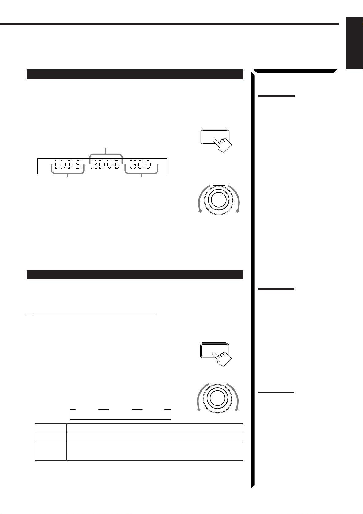
Digital Input (DIGITAL IN) Terminal Setting
SETTING
SETTING
English
When you use the digital input terminals, you have to register what components are
connected to which terminals (DIGITAL IN 1/2/3).
On the front panel
only
:
1. Press SETTING repeatedly until “DIGITAL IN”
appears on the display.
The display changes to show the current setting.
DIGITAL 2 terminal setting
DIGITAL 1 terminal setting
DIGITAL 3 terminal setting
MULTI JOG
2. Turn MULTI JOG to select the appropriate digital terminal
setting, while the indication of the previous step is still on
the display.
As you turn it, the display changes to show the following:
“ 1 DBS 2 DVD 3 CD “ 1 MD 2 DVD 3 CD “ 1 MD 2 DBS 3 CD
“ 1 MD 2 DBS 3 DVD “ 1 CD 2 DVD 3 MD “ 1 CD 2 DBS 3 MD
“ 1 CD 2 DBS 3 DVD “ 1 DVD 2 CD 3 MD “ 1 DVD 2 DBS 3 MD
“ 1 DVD 2 DBS 3 CD “ 1DBS 2 CD 3 MD “ DBS 2 DVD 3 MD
“ (back to the beginning)
Note:
When shipped from the factory,
the DIGITAL IN terminals can be
used as the digital input for the
following components.
• DIGITAL 1 (coaxial): For DBS
tuner
• DIGITAL 2 (optical): For DVD
player
• DIGITAL 3 (optical): For CD
player
Setting the Speakers for the DSP Modes
To obtain the best possible surround sound of the DSP modes, you have to register the
information about the speakers arrangement after all connections are completed.
Front, Center, and Rear Speaker Setting
Register the sizes of the other speakers.
On the front panel
only
:
1. Press SETTING repeatedly until “FRONT SPK” (Front
Speaker), “CENTER SPK” (Center Speaker) or “REAR
SPK” (Rear Speaker) appears on the display.
The display changes to show the current setting.
2. Turn MULTI JOG to select the appropriate item about
your front, center and rear speakers, while the indication of
MULTI JOG
the previous step is still on the display.
As you turn it, the display changes to show the following:
LARGE SMALL NONE
LARGE Select this when the speaker size is relatively large.
SMALL Select this when the speaker size is relatively small.
NONE Select this when you have not connect a speaker. (Not selectable
for the front speakers)
Note:
When you change your
speakers, you need to register
the information about the
speakers again.
Notes:
• If the size of the cone speaker
unit built in your speaker is
greater than 12 cm (4 3/
inches), select “LARGE,” and
if it is smaller than 12 cm (4 3/
inches), select “SMALL.”
• If you have selected “NO” for
the subwoofer setting above,
you can only select “LARGE”
for the front speaker setting.
4
4
20
Page 26

SETTING
SETTING
Basic Settings
SETTING
English
Center Delay Time Setting
Register the delay time of the sound from the center speaker, comparing that of the
sound from the front speakers.
If the distance from your listening point to the center speaker is equal to that to the front
speakers, select 0 msec. As the distance to the center speaker becomes shorter, increase
the delay time.
On the front panel
only
:
1. Press SETTING repeatedly until “CENTER DELAY”
appears on the display.
The display changes to show the current setting.
2. Turn MULTI JOG to select the delay time of the center
MULTI JOG
speaker output, while the indication of the previous step is
still on the display.
• Turn it clockwise to increase the delay time from 0 msec
(“C. DELAY 0ms”) to 5 msec (“C. DELAY 5ms”).
• Turn it counterclockwise to decrease the delay time from
5 msec (“C. DELAY 5ms”) to 0 msec (“C. DELAY
0ms”).
Rear Delay Time Setting
Register the delay time of the sound from the rear speakers, comparing that of the sound
from the front speakers.
If the distance from your listening point to the rear speakers is equal to that to the front
speakers, select 0 msec. As the distance to the rear speakers becomes shorter, increase
the delay time.
On the front panel
only
:
1. Press SETTING repeatedly until “REAR DELAY” appears
on the display.
The display changes to show the current setting.
Note:
1 msec increase (or decrease)
in delay time corresponds to 30
cm (11 13/16 inches) decrease (or
increase) in distance.
Notes:
• 1 msec increase (or
decrease) in delay time
corresponds to 30 cm (11 13/
inches) decrease (or
increase) in distance.
• It is recommended that the
rear delay time for Dolby
Digital be set to 5 msec.
16
2. Turn MULTI JOG to select the delay time of the rear
speaker output, while the indication of the previous step is
still on the display.
• Turn it clockwise to increase the delay time from 0 msec
(“R. DELAY 0ms”) to 15 msec (“R. DELAY 15ms”).
• Turn it counterclockwise to decrease the delay time from
15 msec (“R. DELAY 15ms”) to 0 msec (“R. DELAY
0ms”).
Crossover Frequency Setting
Small speaker cannot reproduce the bass sound very well. So, if you have used a small
speaker any for the front, center, or rear channels, this receiver automatically reallocate
the bass elements, originally assigned to the channel for which you have connected the
small speaker, to another channel (for which you have connected the large speaker).
To use this function properly, you need to set this crossover frequency level according to
the size of the small speaker connected.
On the front panel
only
:
1. Press SETTING repeatedly until “CROSSOVER FRQ”
(Crossover Frequency) appears on the display.
The display changes to show the current setting.
21
MULTI JOG
Note:
This function takes effect only
when playing back a source
using the Dolby Digital.
However, if you have selected
“LARGE” for all speakers (see
page 20), this function will not
take effect.
Page 27

English
SETTING
SETTING
2. Turn MULTI JOG to select the crossover frequency level
MULTI JOG
according to the size of the small speaker connected, while
the indication of the previous step is still on the display.
As you turn it, the display changes to show the following:
CROSS: 80Hz CROSS:100Hz CROSS:120Hz
CROSS: 80Hz Select this when the cone speaker unit built in the speaker is
about 12 cm (4 3/4 inches).
CROSS:100Hz Select this when the cone speaker unit built in the speaker is
about 10 cm (3 15/16 inches).
CROSS:120Hz Select this when the cone speaker unit built in the speaker is
about 8 cm (3 3/16 inches).
Low Frequency Effect Attenuator Setting
If the bass sound is distorted while playing back a source using Dolby Digital, follow
the procedure below.
On the front panel
only
:
1. Press SETTING repeatedly until “LFE ATT” (Low
Frequency Effect Attenuator) appears on the display.
The display changes to show the current setting.
2. Turn MULTI JOG to select the low frequency effect
MULTI JOG
attenuator level, while the indication of the previous step is
still on the display.
As you turn it, the display changes to show the following:
Note:
This function takes effect only
when playing back a source
using the Dolby Digital.
LFE ATT: 0dB LFE ATT:10dB
LFE A TT : 0dB Normally select this.
LFE A TT :10dB Select this when the bass sound is distorted.
Dynamic Range Compression Setting
You can compress the dynamic range (difference between maximum sound and
minimum sound) of the reproduced sound. This is useful when enjoying surround sound
at night.
On the front panel
only
:
1. Press SETTING repeatedly until “D. RANGE COMP.”
(Dynamic Range Compression) appears on the display.
The display changes to show the current setting.
2. Turn MULTI JOG to select the appropriate item about the
compression level, while the indication of the previous step
is still on the display.
As you turn it, the display changes to show the following:
COMP.: OFF
COMP.: MID
COMP.: MAX
COMP.: OFF Select this when you want to enjoy surround with its full
dynamic range. (No effect applied.)
COMP.: MID Select this when you want to reduce the dynamic range a
little. (Factory setting.)
COMP.: MAX Select this when you want to apply the compression effect
fully. (Useful at night.)
Note:
This function takes effect only
when playing back a source
using the Dolby Digital.
MULTI JOG
22
Page 28

One Touch Operation
This receiver can memorize the optimum sound settings for each playing source.
English
About the One Touch Operation
JVC’s One Touch Operation function is used to assign and store different sound settings
for each different playing source. By using this function, you do not have to change the
settings every time you change the source. The stored settings for the newly selected
source are automatically recalled.
The following can be stored for each source:
• Volume level (see page 15)
• Input attenuator mode (see page 17)
• Subwoofer output level (see page 17)
• Input mode (see page 18)
• Balance (see page 19)
• Loudness (see page 19)
• SEA modes (see page 32)
• DSP modes
– 3D-PHONIC mode settings (see page 35)
– DAP mode settings (see page 38)
– Surround mode settings (see page 40 and 43)
Using the One Touch Operation
On the front panel
To store the sound settings
1. Press ONE TOUCH OPERATION.
The ONE TOUCH OPERATION lamp lights up, then the
previously memorized settings are recalled.
only
:
ONE TOUCH OPERATION
Note:
If the source is FM or AM (MW/
LW), you can assign a different
setting for each band.
2. Adjust the sound using the functions listed above.
The newly adjusted settings are memorized.
To recall the sound settings
With the ONE TOUCH OPERATION lamp lit, the settings for the
currently selected source is recalled when the source is selected.
To cancel the One Touch Operation function
Press ONE TOUCH OPERATION so that the lamp goes off.
(Even though the One Touch Operation function is canceled, the
recalled sound effects remain active.)
ONE TOUCH OPERATION
23
Page 29

Receiving Radio Broadcasts
FM/AM TUNING
You can browse through all the stations or use the preset function to go immediately to a particular
station.
IMPORTANT:
When using the Remote Control, check to see if its remote control
AUDIO/TV
/VCR
mode selector is set to the correct position:
CATV
To operate this receiver, set it to “AUDIO/TV/VCR” (except when
/DBS
selecting the DBS tuner as the source).
Tuning in Stations Manually
English
On the front panel
only
:
1. Press FM/AM TUNING to select the band.
Each time you press the button, the band alternates between
FM and AM (MW/LW).
2. Turn MULTI JOG until you find the frequency you
MULTI JOG
want.
• Turning it clockwise increases the frequency.
• Turning it counterclockwise decreases the frequency.
Using Preset Tuning
Once a station is assigned to a channel number, the station can be quickly tuned. You
can preset up to 40 stations at random.
To store the preset stations
On the front panel
only
:
1. Tune in the station you want to preset (see above).
If you want to store the FM reception mode for this station, select the FM reception
mode you want. See page 25 for details.
Notes:
• When you turn MULTI JOG
quickly in step 2, the
frequency keeps changing
until a station is tuned in.
• When a station of sufficient
signal strength is tuned in, the
TUNED indicator lights up on
the display.
When an FM stereo program
is received, the STEREO
indicator also lights up.
2. Press TUNER/SEA MEMORY.
“CH-” appears and the channel number position starts flashing
on the display for about 5 seconds.
3. Turn MULTI JOG to select a channel number while
the channel number position is flashing.
4. Press TUNER/SEA MEMORY again while the
selected channel number is flashing on the display.
The selected channel number stops flashing.
The station is assigned to the selected channel number.
TUNER/SEA MEMORY
MULTI JOG
TUNER/SEA MEMORY
Continued to the next page.
Note:
You can use the 10 keys on the
remote control to select the
preset number. When using the
10 keys, be sure that they are
activated for tuner, not for the
CD and others. (See page 63.)
24
Page 30

TUNER PRESET
Receiving Radio Broadcasts
English
5. Repeat steps 1 to 4 until you store all the stations you
want.
To erase a stored preset station
Storing a new station on a used number erases the previously stored one.
To tune in a preset station
On the front panel:
1. Press TUNER PRESET.
2. Turn MULTI JOG to select a preset channel.
MULTI JOG
From the remote control:
1. Press FM/AM.
Each time you press the button, the band alternates
between FM and AM (MW/LW).
2. Press 10 keys to select a preset channel number.
• For channel number 5, press 5.
• For channel number 15, press +10 then 5.
• For channel number 20, press +10 then 10.
• For channel number 30, press +10, +10, then 10.
Selecting the FM Reception Mode
When an FM stereo broadcast is hard to receive or noisy, set the FM reception mode to
“MONO.” (When shipped from the factory, this mode has been set to “AUTO.”)
You can change the FM reception mode while receiving an FM broadcast.
Press FM MODE on the front panel or FM MODE/
FM MODE
MUTE on the remote control.
Each time you press the button, the FM reception mode
alternates between “AUTO” and “MONO.”
AUTO: When a program is broadcasted in stereo, you will hear stereo
sound; when in monaural, you will hear monaural sounds. This
mode is also useful to suppress static noise between stations.
The MUTE AUTO indicator lights up on the display.
MONO: Reception will be improved although you will lose the stereo effect.
In this mode, you will hear noise while tuning into the stations.
The MUTE AUTO indicator goes off on the display.
FM/AM
CNTRCNTR TONE
213
TEST
EFFECT
SEA MODE SUBWOOFER
10
RETURN
REAR L
ENTER
546
REAR R
87
/P
0
FM MODE/MUTE
SUBWOOFER
9
+10
100+
0
FM MODE/MUTE
MENU
Note:
When you use the 10 keys on
the remote control, be sure that
they are activated for tuner, not
for the CD and others. (See
page 63.)
Notes:
• You can store the FM
reception mode for each
preset station.
• When using the FM MODE/
MUTE button, be sure that the
10 keys are activated for
tuner, not for the CD and
others. (See page 63.)
25
Page 31

Assigning Names to Preset Stations
TUNER PRESET
TUNER PRESET
You can assign a name of up to four characters to each preset station. When a preset
station is tuned in, its assigned name will appear on the display.
English
On the front panel
only
:
1. Tune in a preset station.
See page 25 for details.
2. Press TUNER/SEA MEMORY.
The preset channel number starts flashing for about 5 seconds.
CH–
3. Press TUNER PRESET, while the preset channel number is
flashing.
The first character position starts flashing.
CH–
VOLUME
4. Turn MULTI JOG to select the first character, while
the first character position is flashing.
You can use characters listed below.
CH–
TUNER/SEA MEMORY
MULTI JOG
Note:
If you turn MULTI JOG while the
preset channel number is
flashing, you can change
the preset channel number.
Note on step 3 to 7:
You cannot select any entry
after the indication on the
display stops flashing.
In this case, repeat the
procedure from step 2 again.
5. Press TUNER PRESET, while a character you want is
flashing.
The next (or previous) character position starts flashing.
CH–
6. Repeat steps 4 and 5 to enter up to four characters.
7. Press TUNER/SEA MEMORY while the last selected
character is flashing after you have assigned a name.
To erase the input characters
Insert spaces using the same procedure described above.
Available characters
Space
CBADEGFHIJKLMNO
SRQTUWVXYZ01234P
MULTI JOG
TUNER/SEA MEMORY
87695
26
Page 32

Receiving Radio Broadcasts
English
Using the RDS (Radio Data System) to Receive FM Stations
RDS allows FM stations to send an additional signal along with their regular program
signals. For example, the stations send their station names, as well as information about
what type of program they broadcast, such as sports or music, etc.
When tuned to an FM station which provides the RDS service, the RDS indicator lights
up on the display.
With the receiver, you can receive the following types of RDS signals.
PS (Program Service): shows commonly known station names
PTY (Program Type): shows types of broadcast programs
RT (Radio Text): shows text messages the station sends
EON (Enhanced Other Network): see page 31.
What Information Can RDS Signals Provide?
You can see the RDS signals the station sends on the display.
To show the RDS signals
On the front panel:
Press DISPLAY MODE while listening to an FM
station.
Each time you press the button, the display changes to show
you the following information:
PS PTY RT Frequency
PS (Program Service):
While searching, “PS” appears and then the station names will be displayed.
“NO PS” appears if no signal is sent.
PTY (Program Type):
While searching, “PTY” appears and then the type of the broadcast program will
be displayed. “NO PTY” appears if no signal is sent.
RT (Radio Text):
While searching, “RT” appears and then text messages the station sends will be
displayed. “NO RT” appears if no signal is sent.
Station Frequency:
Station frequency (non-RDS service)
DISPLAY MODE
Note:
RDS may not operate correctly if
the station tuned is not
transmitting RDS signal properly
or if the signal strength is weak.
Notes:
• If searching finishes at once,
“PS”, “PTY”, and “RT” will not
appear on the display.
• Even if you press DISPLAY
MODE while listening to an
AM (MW/LW) station, the
display only shows station
frequency.
• RDS is not available for AM
(MW/LW) broadcasts.
When pressing DISPLAY MODE on the remote control:
Make sure that you have selected FM station using the
remote control.
If not, the DISPLAY MODE button does not work for tuner
operation. (Pressing FM/AM activates the remote control
for tuner operation.)
27
STOP
DISPLAY MODE
Page 33

English
Searching for a Program by PTY Codes
One of the advantages of the RDS service is that you can locate a particular kind of
program from the preset channels by specifying the PTY codes.
To search for a program using the PTY codes
On the front panel:
1. Press PTY SEARCH while listening to an FM
station.
“PTY SELECT” flashes on the display.
2. Turn MULTI JOG until the PTY code you want
appears on the display while “PTY SELECT” is
flashing.
As you turn it, the display gives you the PTY codes
described on page 29.
3. Press PTY SEARCH again while the PTY code selected in
the previous step is still on the display.
While searching, “SEARCH” and the selected PTY
code alternate on the display.
The receiver searches 40 preset channels, stops when it
finds the one you have selected, and tunes in that
station.
PTY SEARCH
MULTI JOG
PTY SEARCH
Note:
FM stations must be preset to
use the PTY codes.
To continue searching after the first stop
Press PTY SEARCH again while the indications on the display are flashing.
If no program is found, “NOTFOUND” appears on the display.
To stop searching any time during the process
Press PTY SEARCH while searching.
28
Page 34

Receiving Radio Broadcasts
PLAY
PTY SEARCH
PLAY
PTY SEARCH
English
From the remote control:
Before starting the procedure below, make sure you have selected FM station only using
the remote control. If not, the following RDS operating buttons do not work for tuner
operation. (Pressing FM/AM activates the remote control for tuner operation.)
1. Press PTY SEARCH while listening to an FM
station.
“PTY SELECT” flashes on the display.
Note:
When selecting the PTY codes
by pressing PTY +, NEWS
always appears first.
When selecting the PTY codes
by pressing PTY –, ALARM
always appears first.
or
P
FF / ¢
2. Press PTY +/– until the PTY code you want appears
on the display while “PTY SELECT” is flashing.
The display gives you the PTY codes described to the
–
Y
T
P
4 / REW
right.
3. Press PTY SEARCH again while the PTY code
selected in previous step is still on the display.
While searching, “SEARCH” and the selected PTY
code alternate on the display.
The receiver searches 40 preset channels, stops when it
finds the one you have selected, and tunes in that
station.
To continue searching after the first stop
Press PTY SEARCH again while the indications on the display are flashing.
If no program is found, “NOTFOUND” appears on the display.
To stop searching any time during the process
Press PTY SEARCH while searching.
When an emergency broadcast (ALARM signal) is sent from an FM station:
The receiver automatically tunes in the station except in the following cases:
• When you are listening to non-RDS stations (all AM — MW/LW and some FM
stations).
• When the receiver is in standby mode.
While receiving an emergency broadcast, “ALARM” appears on the display.
+
Y
T
Descriptions of the PTY
codes:
NEWS
ALARM
TEST
DOCUMENT
FOLK M
(FOLK MUSIC)
OLDIES
NATIONAL
(NATIONAL MUSIC)
CONTRY
JAZZ
LEISURE
TRAVEL
PHONE IN
AFFAIRS
INFO
(INFORMATION)
SPORT
EDUCATE
(EDUCATION)
DRAMA
CULTURE
SCIENCE
VARIED
POP M
(POP MUSIC)
ROCK M
(ROCK MUSIC)
M.O.R. M
(MIDDLE-OF-THE-
ROAD MUSIC)
The TEST signal is used for equipment test — whether it can receive the ALARM
signal correctly.
The TEST signal makes the receiver work in the same way as the ALARM signal does.
If an TEST signal is received, the receiver automatically switches to the station
broadcasting the TEST signal.
While receiving an test signal, “TEST” appears on the display.
29
RELIGION
SOCIAL A
(SOCIAL AFFAIRS)
CHILDREN
FINANCE
LIGHT M
(LIGHT MUSIC)
CLASSICS
OTHER M
(OTHER MUSIC)
WEATHER
Page 35

Switching to a Broadcast Program of Your Choice Temporarily
EON
Another convenient RDS service is called “EON (Enhanced Other Network).”
The EON indicator lights up while receiving a station with the EON code.
This allows the receiver to switch temporarily to a broadcast program of your choice
(NEWS, TA, and/or INFO) from a different station except in the following cases:
• When you are listening to a non-RDS stations (all AM — MW/LW and some FM
stations).
• When the last received FM station is a non-RDS station.
• When the receiver is in standby mode.
English
Note:
FM stations must be preset to
use the EON function.
On the front panel
1. Press EON so that the last selected program type
appears on the display.
The receiver enters EON standby mode*.
2. Press TA/NEWS/INFO until the program type you
want appears on the display.
Each time you press the button, the display changes to
show the following.
TA
TA: Traffic Announcement in your area.
NEWS: News.
INFO: Program the purpose of which is to impart advice in the widest sense.
CASE 1 If there is no station broadcasting the program you have selected
The receiver continues playing the current source (all sources except AM — MW/
LW).
NEWS/INFO
NEWS
only:
INFO
TA/INFO
TA/NEWS/INFO
TA/NEWS/INFO
TA/NEWS
‘
Note:
* When the receiver is in EON
standby mode, the receiver is
ready to receive the EON data
(TA/NEWS/INFO) you select.
When a station starts broadcasting the program you have selected, the receiver
automatically switches to the station. The indicator of received PTY code starts
flashing.
‘
When the program is over, the receiver goes back to the previously selected source,
but still remains in EON standby mode. The indicator of received PTY code stops
flashing and remains lit.
Continued to the next page.
30
Page 36

Receiving Radio Broadcasts
EON
English
CASE 2 If there is a station broadcasting the program you have selected
The receiver changes the source (all sources except AM — MW/LW), and tunes in
the station. The indicator of received PTY code starts flashing.
‘
When the program is over, the receiver goes back to the previously selected source,
but still remains in EON standby mode. The indicator of received PTY code stops
flashing and remains lit.
CASE 3 If the FM station you are listening is broadcasting the program you
have selected
The receiver continues to receive the station but the indicator of received PTY code
starts flashing.
‘
When the program is over, the indicator of received PTY code stops flashing and
remains lit, but the receiver remains in EON standby mode.
To stop listening to the program selected by EON
Press EON so that the program type (TA/NEWS/INFO) goes off
from the display. The receiver enters EON off mode and goes back
to the previously selected source.
Each time you press EON, the EON mode alternates between
standby mode and off mode.
Notes:
• EON data sent from some
stations may not be
compatible with this receiver.
• In EON standby mode, if you
change the source to AM
(MW/LW) or if you carry out
synchronized recording (see
page 55), EON standby mode
is canceled temporarily. The
receiver goes back to EON
standby mode again when you
have finished that operation.
• While listening to a program
tuned in by the EON function,
you can only use STANDBY/
ON
VOLUME (on the front panel)
and AUDIO (on the remote
control).
• While listening to a program
tuned in by the EON function,
you cannot perform the onscreen operations (pages 47
and 57).
• When the receiver is turned off
(into standby mode), the EON
function is also turned off.
, EON, MASTER
CAUTION:
When the source alternates
intermittently between the
station tuned in by the EON
function and the currently
selected source, press EON to
cancel the EON function. This is
not a malfunction of the receiver.
31
Page 37
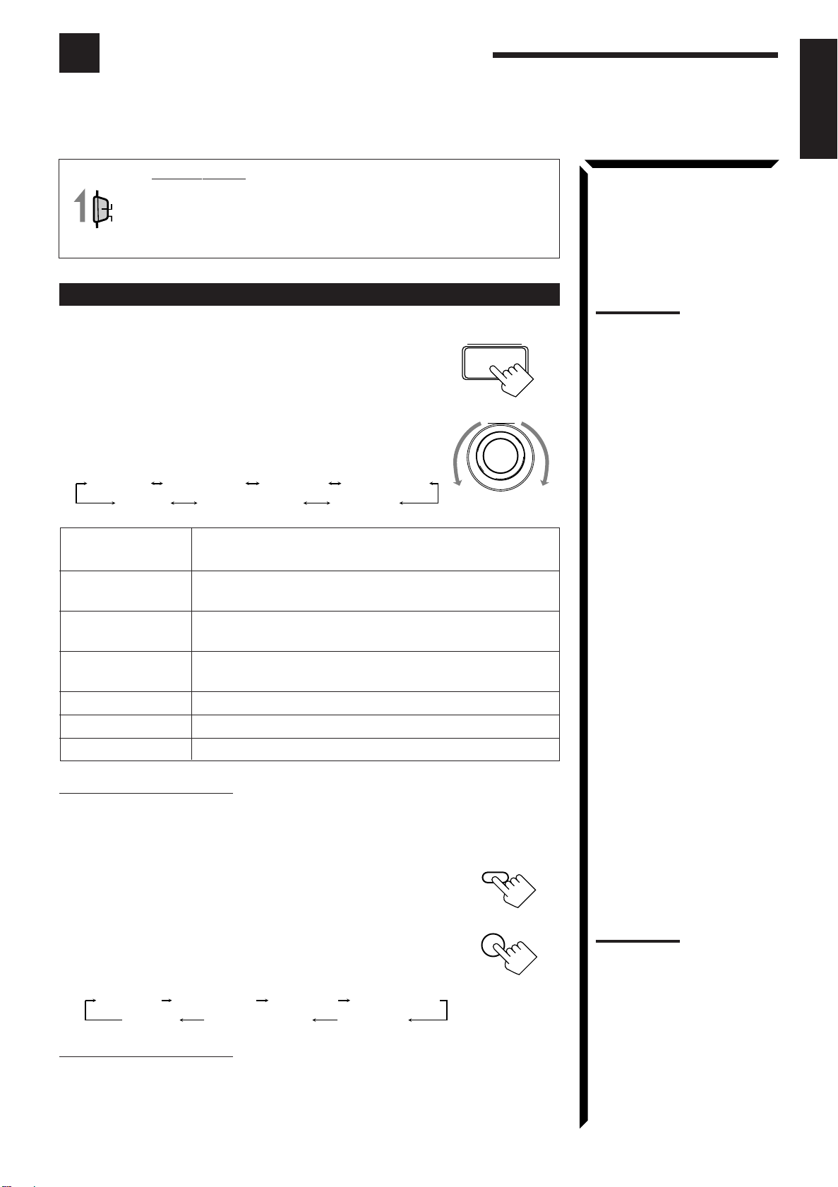
Using the SEA Modes
SEA MODE
The SEA (Sound Effect Amplifier) modes give you control of the way your music sounds.
IMPORTANT:
AUDIO/TV
When using the Remote Control, check to see if its remote control
/VCR
mode selector is set to the correct position:
CATV
To operate this receiver, set it to “AUDIO/TV/VCR” (except when
/DBS
selecting the DBS tuner as the source).
English
Selecting Your Favorite SEA Mode
On the front panel:
1. Press SEA MODE.
The display changes to show the current setting.
2. Turn MULTI JOG until the mode you want appears on the
display, while the indication of the previous step is still on
the display.
As you turn it, the SEA mode changes as follows:
SEA ROCK SEA MUSICAL SEA MOVIE
SEA USERMODESEA OFF
SEA COUNTRY
SEA JAZZ
SEA ROCK: Gives a heavy sound. Both high and low frequencies are
boosted.
SEA MUSICAL: Enhance the mid-frequency range, which the human voice is
mostly made up of.
SEA MOVIE: Adds breadth to sounds so you feel like you are in a movie
theater.
SEA COUNTRY: Enhances the high-frequency range so that instruments such
the violin and banjo are emphasized.
SEA JAZZ: Gives a feeling of a live atmosphere. Good for acoustic music.
SEA USERMODE: Your original SEA adjustment (see page 33).
SEA OFF: No SEA mode is applied (see below).
MULTI JOG
Notes:
• The SEA modes cannot be
used for recording.
• When the SEA mode is turned
on, the SEA indicator lights up
on the display.
• When the SEA mode is used
with the DAP mode (see page
38), sounds may be distorted.
If this happens, turn off the
DAP mode or decrease the
effect level of the DAP mode.
To cancel the SEA mode
Turn MULTI JOG until “SEA OFF” appears in step 2 above.
The SEA indicator goes off from the display.
From the remote control:
1. Press SOUND CONTROL.
10 keys are activated for sound adjustments.
2. Press SEA MODE repeatedly until the SEA mode you want
appears on the display.
Each time you press the button, the SEA mode changes
as follows:
SEA ROCK SEA MUSICAL SEA MOVIE
SEA USERMODESEA OFF
To cancel the SEA mode
Press SEA MODE until “SEA OFF” appears in step 2 above.
The SEA indicator goes off from the display.
SEA COUNTRY
SEA JAZZ
SOUND
CONTROL
SEA MODE
10
RETURN
Note:
When the SEA mode is turned
on, the SEA indicator lights up
on the display.
32
Page 38

SEA ADJUST
Using the SEA Modes
English
Creating Your Own SEA Mode
You can adjust and store your own SEA adjustment into memory (SEA USERMODE).
On the front panel
only
:
If you do not want to store your adjustment, but rather want to adjust the SEA
temporarily, skip step 4 below.
1. Press SEA ADJUST repeatedly until the frequency range
(100Hz, 1kHz or 10kHz) you want appears on the display.
S E A
FR
100 1k 10k
S E A
FR
100 1k 10k
VOLUME
VOLUME
2. Turn MULTI JOG to adjust the SEA level of the selected
frequency range, while the indication of the previous step is
still on the display.
• Turning it clockwise increases the level.
• Turning it counterclockwise decreases the level.
MULTI JOG
This FR means this adjustment can be
applied to the front speakers only
S E A
FR
100 1k 10k
3. Repeat step 1 and 2 to adjust other frequency ranges if
necessary.
4. Press TUNER/SEA MEMORY, while the indication of the
TUNER/SEA MEMORY
previous step is still on the display.
Your adjustment is stored into the SEA USERMODE.
To recall your own SEA adjustment
See page 32.
To erase a stored adjustment
Storing a new adjustment into SEA USERMODE erases the previously stored one.
33
Page 39

Using the DSP Modes
The built-in Surround Processor provides three types of the DSP (Digital Signal Processor) mode — 3DPHONIC mode, DAP (Digital Acoustic Processor) mode and Surround mode (Dolby Digital, Dolby Pro Logic
and JVC’s Theater Surround.)
On the 3D-PHONIC mode
The 3D-PHONIC mode gives you such a
nearly surround effect as it is reproduced
through the Dolby Surround decoder, which
is widely used to reproduce sounds with a
feeling of movement like those experienced
in movie theaters. The 3D-PHONIC mode is
the result of research on sound localization
technology carried out at JVC for many
years and makes it possible to reproduce the
surround sound with only two front
speakers.
On the DAP mode
The sound heard in a concert hall or club
consists of direct sound and indirect sound
— early reflections and reflections from
behind. Direct sounds reach the listener
directly without any reflection. On the other
hand, indirect sounds are delayed by the
distances of the ceiling and walls. These
direct sounds and indirect sounds are the
most important elements of the acoustic
surround effects. The DAP mode can create
these important elements, and gives you a
real “being there” feeling.
Early reflections
Direct sounds
Reflections from
behind
Notes:
• The DSP modes has no effect
on monaural sources.
• You can not use the two types
of the DSP modes at the same
time.
IMPORTANT:
When recording the digital
source, turn off the DSP mode.
English
On Surround mode
With this receiver, you can use two types of
the surround mode.
Dolby Surround (Dolby Digital and
Dolby Pro Logic)
Used to watch the soundtracks of software
encoded with Dolby Digital (bearing the
mark
DIGITAL
(bearing the mark
) or with Dolby Surround
DOLBY SURROUND
).
Dolby Digital and Dolby Pro Logic can be
selected automatically according to
software played back.
JVC’s Theater Surround
In order to reproduce a more realistic sound field in your listening room while playing
soundtracks of software encoded with Dolby Digital (bearing the mark
with Dolby Surround (bearing the mark
DOLBY SURROUND
), Theater Surround has been
DIGITAL
) or
designed to create a real “being there” feeling.
Note:
To enjoy the software encoded
with Dolby Digital, you must
connect the source component
using the digital terminal on the
rear of this receiver.
Manufactured under license
from Dolby Laboratories.
“Dolby,” “Pro Logic,” the doubleD symbol are trademarks of
Dolby Laboratories. Confidential
Unpublished works. ©1992–
1997 Dolby Laboratories, Inc. All
rights reserved.
34
Page 40

Using the DSP Modes
DSP MODE
English
IMPORTANT:
When using the Remote Control, check to see if its remote control
AUDIO/TV
/VCR
mode selector is set to the correct position:
To operate this receiver, set it to “AUDIO/TV/VCR” (except when
CATV
/DBS
selecting the DBS tuner as the source).
Using the 3D-PHONIC Modes
When using the 3D-PHONIC modes, you need only two front speakers to reproduce the
soundtracks of software encoded with Dolby Digital (bearing the mark
with Dolby Surround (bearing the mark
DOLBY SURROUND
).
DIGITAL
) or
On the front panel:
1. Select and play the source encoded with Dolby Digital (bearing the mark
DIGITAL
) or with Dolby Surround (bearing the mark
• When you play back the source encoded with Dolby Digital and select the digital
input for that source, the Ÿ DIGITAL indicator lights up on the display.
2. Press DSP MODE.
The current DSP mode appears on the display.
3. Turn MULTI JOG until the mode — 3D ACTION (or 3D
DIGITAL), 3D DRAMA, or 3D THEATER — you want
appears on the display, while the indication of the previous
step is still on the display.
As you turn it, the DSP modes change as follows (the 3DPHONIC and DSP indicators also light up on the display):
When the digital input is selected to play the source encoded with Dolby
Digital:
DIG-THEATER
DSP OFF
HEADPHONE
3D DIGITAL
For other sources:
LIVE CLUBTHEATER
DANCE CLUB
DSP OFF
3D THEATER
3D DRAMA
3D ACTION
3D ACTION: Best for action and war movies — where the action is fast and
explosive.
3D DRAMA: Best for dramas and romantic movies — where the action is
slow and soft.
3D THEA TER: Reproduces the sound field of a theater.
3D DIGITAL: Reproduces multi-sound source encoded with Dolby Digital.
DSP OFF
:
No DSP mode is applied.
DOLBY SURROUND
HALL
PAVILION
HEADPHONE
).
MULTI JOG
Notes:
• To enjoy the software
encoded with Dolby Digital,
you must connect the source
component using the digital
terminal on the rear of this
receiver.
• The 3D-PHONIC mode is not
used with the other DSP
modes such as the DAP
mode and the Surround
mode. When the 3D-PHONIC
mode is turned on, the other
DSP mode, if used, will be
turned off.
Notes on the indications:
• The indicator of the selected
DSP mode also lights up on
the display while selecting.
• The PRO LOGIC indicator
lights up when the Dolby Pro
Logic decoder built in this
receiver is activated.
• The Dolby Pro Logic decoder
is used not only for the analog
sources but also for the
sources encoded with Dolby
Digital in the following cases:
– When only front channel
signals are encoded.
– When front channel and
monaural rear channel
signals are encoded.
While the Dolby Pro Logic is
activated for this type of Dolby
Digital source, the Ÿ DIGITAL
indicator goes off.
For the other modes, see pages 38 and 43.
If you need to make any adjustment, go to the following steps.
35
Page 41

English
4. Press BALANCE/SURROUND ADJUST repeatedly until
“DSP EFFECT” appears on the display.
The display changes to show the current setting.
5. Turn MULTI JOG to select the effect level, while the indication of
the previous step is still on the display.
As you turn it, the effect level changes as follows:
DSP EFFECT 1 DSP EFFECT 2
DSP EFFECT 5
DSP EFFECT 4
DSP EFFECT 3
As the number increases, the selected 3D-PHONIC mode
becomes stronger.
To cancel the 3D-PHONIC mode
Turn MULTI JOG until “DSP OFF” appears in step 3.
The 3D-PHONIC and DSP indicators go off from the display.
BALANCE/SURROUND
ADJUST
MULTI JOG
Note:
Once you have adjusted the 3DPHONIC modes, it is memorized
for each 3D-PHONIC mode.
36
Page 42

SURROUND
MODE
Using the DSP Modes
English
From the remote control:
1. Select and play the source encoded with Dolby Digital (bearing the mark
DIGITAL
) or with Dolby Surround (bearing the mark
• When you play back the source encoded with Dolby Digital and select the digital
input for that source, the Ÿ DIGITAL indicator lights up on the display.
2. Press SURROUND MODE repeatedly until the mode — 3D
ACTION (or 3D DIGITAL), 3D DRAMA, or 3D THEATER
— you want appears on the display.
Each time you press the button, the DSP modes change as
follows (the 3D-PHONIC and DSP indicators also light up
on the display):
DOLBY SURROUND
).
Note:
The 3D-PHONIC mode is not
used with the other DSP modes
such as the DAP mode and the
Surround mode. When the 3DPHONIC mode is turned on, the
other DSP mode, if used, will be
turned off.
When the digital input is selected to play the source encoded with Dolby
Digital:
DOLBY DIGITAL
OFF
3D DIGITAL
DIG-THEATER
HEADPHONE
For other sources:
PRO LOGIC
OFF
3D THEATER
THEATER
3D DRAMA
LIVE CLUB
3D ACTION
DANCE CLUB
HEADPHONE
3. Press SOUND CONTROL.
10 keys are activated for sound adjustments.
4. Press EFFECT to select the effect level.
Each time you press the button, the effect level changes as follows:
DSP EFFECT 1 DSP EFFECT 2
DSP EFFECT 5
DSP EFFECT 4
DSP EFFECT 3
As the number increases, the selected 3D-PHONIC mode becomes
stronger.
To cancel the 3D-PHONIC mode
Press SURROUND MODE repeatedly until “OFF” appears.
The 3D-PHONIC and DSP indicators go off from the display.
HALL
PAVILION
SOUND
CONTROL
EFFECT
7
/P
Notes on the indications:
• The indicator of the selected
DSP mode also lights up on
the display while selecting.
• The PRO LOGIC indicator
lights up when the Dolby Pro
Logic decoder built in this
receiver is activated.
• The Dolby Pro Logic decoder
is used not only for the analog
sources but also for the
sources encoded with Dolby
Digital in the following cases:
– When only front channel
signals are encoded.
– When front channel and
monaural rear channel
signals are encoded.
While the Dolby Pro Logic is
activated for this type of Dolby
Digital source, the Ÿ DIGITAL
indicator goes off.
Note:
Once you have adjusted the 3DPHONIC modes, it is memorized
for each 3D-PHONIC mode.
37
Page 43

Using the DAP Modes
English
You can use five DAP modes — “Live Club, Dance Club, Hall, Pavilion, and
Headphones” for any source.
Among the DAP modes, “Headphones” is very special. It can create the same stereo
sound as you listen through the speakers off air while listening to a source using
headphones. So, you can feel as if you were not using the headphones and listening to
music in a room.
If the digital input is selected to play the source encoded with Dolby Digital, you can
only select “Headphones.”
On the front panel:
DSP MODE
1. Press DSP MODE.
The current DSP mode appears on the display.
2. Turn MULTI JOG until the mode (LIVE CLUB, DANCE
CLUB, HALL, PAVILION, or HEADPHONE) you want
MULTI JOG
appears on the display, while the indication of the previous
step is still on the display.
The DSP indicator also lights up on the display.
As you turn it, the DSP modes change as follows:
HALL
PAVILION
DSP OFF
3D THEATER
LIVE CLUBTHEATER
3D DRAMA
DANCE CLUB
3D ACTION
HEADPHONE
When the digital input is selected to play the source encoded with Dolby
Digital:
DIG-THEATER
DSP OFF
HEADPHONE
3D DIGITAL
Notes:
• The DAP mode is not used
with the other DSP modes
such as the 3D-PHONIC
mode and the Surround
mode. When the DAP mode is
turned on, the other DSP
mode, if used, will be turned
off.
• When the DAP mode is used
with the SEA mode (see page
32), sounds may be distorted.
If this happens, turn off the
SEA mode.
Note:
The indicator of the selected
DSP mode also lights up on the
display while selecting.
LIVE CLUB: Gives the feeling of a live music club with a low ceiling.
DANCE CLUB: Gives a throbbing bass beat.
HALL: Gives clear vocal and the feeling of a concert hall.
PAVILION: Gives the spacious feeling of a pavilion with a high ceiling.
HEADPHONE:
DSP OFF
:
Gives a spacious stereo effect when listening with headphones.
No DSP mode is applied.
For the other modes, see pages 35 and 43.
If you need to make any adjustment, go to the following steps.
3. Adjust the speaker output levels as follows.
BALANCE/SURROUND
1) Press BALANCE/SURROUND ADJUST repeatedly
until one of the indications appears on the display.
“REAR L LEVEL”: To adjust the left speaker level.
“REAR R LEVEL”: To adjust the right speaker level.
2) Turn MULTI JOG to adjust the selected speaker output
level (from –10 dB to +10 dB), while the indication of the
previous step is still on the display.
3) Repeat 1) and 2) to adjust the other speaker output
levels.
Continued to the next page.
ADJUST
MULTI JOG
Note:
When you select
“HEADPHONE,” you cannot go
to the following steps. No
adjustments can be made for
“HEADPHONE.”
Note:
You cannot adjust the rear
speaker levels when “REAR
SPK” is set to “NONE” (see
page 20).
38
Page 44

SURROUND
MODE
Using the DSP Modes
English
4. Adjust the effect level.
BALANCE/SURROUND
1) Press BALANCE/SURROUND ADJUST repeatedly
until “DSP EFFECT” appears on the display.
2) Turn MULTI JOG to select the effect level, while the
indication of the previous step is still on the display.
As you turn it, the effect level changes as follows:
DSP EFFECT 1 DSP EFFECT 2
DSP EFFECT 5
DSP EFFECT 4
DSP EFFECT 3
As the number increases, the selected DAP mode
becomes stronger.
To cancel the DAP mode
Turn MULTI JOG until “DSP OFF” appears in step 2.
The DSP indicator goes off from the display.
From the remote control:
1. Press SURROUND MODE repeatedly until the mode you
want appears on the display.
The DSP indicator also lights up on the display.
Each time you press the button, the DSP modes change as follows (the indicator
of the selected DSP mode also lights up on the display):
PRO LOGIC
OFF
3D THEATER
THEATER
3D DRAMA
LIVE CLUB
3D ACTION
When the digital input is selected to play the source encoded with Dolby
Digital:
DOLBY DIGITAL
OFF
3D DIGITAL
DIG-THEATER
HEADPHONE
DANCE CLUB
HEADPHONE
ADJUST
MULTI JOG
HALL
PAVILION
Note:
Once you have adjusted the
DAP modes, the adjustment is
memorized for each DAP mode.
Note:
The DAP mode is not used with
the other DSP modes such as
the 3D-PHONIC mode and the
Surround mode. When the DAP
mode is turned on, the other
DSP mode, if used, will be
turned off.
Note:
When you select
“HEADPHONE,” you cannot go
to the following steps. No
adjustments can be made for
“HEADPHONE.”
If you need to make any adjustment, go to the following steps.
2. Press SOUND CONTROL.
10 keys are activated for sound adjustments.
3. Adjust the speaker output levels as follows:
• To adjust the left rear speaker level, press REAR•L +/–.
• To adjust the right rear speaker level, press REAR•R +/–.
4. Press EFFECT to select the effect level.
Each time you press the button, the effect level changes as
follows:
DSP EFFECT 1 DSP EFFECT 2
DSP EFFECT 5
DSP EFFECT 4
DSP EFFECT 3
As the number increases, the selected DAP mode becomes
stronger.
To cancel the DAP mode
Press SURROUND MODE repeatedly until “OFF” appears.
The DSP indicator goes off from the display.
39
REAR L
ENTER
56
SOUND
CONTROL
REAR R
89
EFFECT
7
/P
Note:
You cannot adjust the rear
speaker levels when “REAR
SPK” is set to “NONE” (see
page 20).
Note:
Once you have adjusted the
DAP modes, the adjustment is
memorized for each DAP mode.
Page 45

English
SURROUND
MODE
Using the Dolby Digital and Dolby Pro Logic Modes
Once you have adjusted the Dolby Digital and Dolby Pro Logic modes, this receiver
memorizes adjustment for each mode.
To activate the Dolby Digital and Dolby Pro Logic modes, follow the procedure below.
From the remote control:
1. Select and play the source encoded with Dolby Digital (bearing the mark
DIGITAL
) or with Dolby Surround (bearing the mark
• When you play back the source encoded with Dolby Digital and select the digital
input for that source, the Ÿ DIGITAL indicator lights up on the display.
2. Press SURROUND MODE repeatedly until “PRO LOGIC”
or “DOLBY DIGITAL” appears on the display.
Dolby Digital or Dolby Pro Logic is automatically selected
according to the source being played back.
When Dolby Pro Logic is selected, the lamp on the DOLBY SURROUND button
(on the front panel) lights red.
When Dolby Digital is selected, the lamp on the DOLBY SURROUND button (on
the front panel) lights green.
Each time you press the button, the DSP modes change as follows:
When the digital input is selected to play the source encoded with Dolby
Digital:
DOLBY DIGITAL
OFF
3D DIGITAL
DIG-THEATER
HEADPHONE
For other sources:
PRO LOGIC
OFF
3D THEATER
THEATER
3D DRAMA
LIVE CLUB
3D ACTION
If you need to make any adjustment, go to the following steps.
3. Press SOUND CONTROL.
10 keys are activated for sound adjustments.
DOLBY SURROUND
DANCE CLUB
HEADPHONE
CONTROL
).
HALL
PAVILION
SOUND
Notes:
• To enjoy the software encoded
with Dolby Digital, you must
connect the source
component using the digital
terminal on the rear of this
receiver.
• When the signals come into
this receiver through the
analog connection from the
source component, “PRO
LOGIC” is automatically
selected.
• The Surround mode is not
used with the other DSP
modes such as the DAP mode
and 3D-PHONIC mode. When
the Surround mode is turned
on, the other DSP mode, if
used, will be turned off.
Notes on the indications:
• The PRO LOGIC indicator
lights up when the Dolby Pro
Logic decoder built in this
receiver is activated.
• The Dolby Pro Logic decoder
is used not only for the analog
sources but also for the
sources encoded with Dolby
Digital in the following cases:
– When only front channel
signals are encoded.
– When front channel and
monaural rear channel
signals are encoded.
While the Dolby Pro Logic is
activated for this type of Dolby
Digital source, the Ÿ DIGITAL
indicator goes off.
Continued to the next page.
40
Page 46

Using the DSP Modes
CNTR
23
MENU
REAR R
89
English
4. Press TEST to start checking the speaker output balance.
“TEST TONE L” starts flashing on the display, and a test
TEST
4
tone comes out of the speakers in the following order:
TEST TONE L TEST TONE C TEST TONE R
(Left front speaker)
C
L
LS
R
RS
TEST TONE LS
(Left rear speaker)
The speaker indicators also light on the display while the test tone
comes out of the speakers.
L: Lights when the test tone comes out of the left front speaker.
C: Lights when the test tone comes out of the center speaker.
R: Lights when the test tone comes out of the right front speaker.
RS: Lights when the test tone comes out of the right rear speaker.
LS: Lights when the test tone comes out of the left rear speaker.
(Center speaker)
TEST TONE RS
(Right rear speaker)
(Right front speaker)
IMPORTANT:
• Output the test tone while playing back an audio source.
With the DVD digital input selected as the source, no test tone may come out while
no signal is input to this receiver.
• Test tone comes out even while playing back a source encoded with Dolby Digital. In
this case, the PRO LOGIC indicator lights up on the display.
5. Adjust the speaker output levels as follows:
• To adjust the center speaker level, press CNTR +/–.
• To adjust the left rear speaker level, press REAR•L +/–.
REAR L
• To adjust the right rear speaker level, press REAR•R +/–.
ENTER
56
6. Press TEST again to stop the test tone.
TEST
4
7. Press CNTR TONE to select the center tone level you want.
The center tone adjustment affects the mid-frequency
range, which the human voice is mostly made up of.
Each time you press the button, the display changes to
show the following:
SHARP1 SHARP2FLATSOFT2 SOFT1
CNTR TONE
1
Notes:
• No test tone comes out of the
center speakers when
“CENTER SPK” is set to
“NONE” (see page 20).
• No test tone comes out of the
rear speakers when “REAR
SPK” is set to “NONE” (see
page 20).
• If the TV is turned on and the
proper video input is selected
on the TV, the test tone
screen will appear on the TV.
Notes:
• You can adjust the speaker
output levels and center tone
without outputting the test
tone.
• You cannot adjust the center
speaker output level when
“CENTER SPK” is set to
“NONE” (see page 20).
• You cannot adjust the rear
speaker levels when “REAR
SPK” is set to “NONE” (see
page 20).
Note:
The center tone cannot be
adjusted when “CENTER SPK”
is set to “NONE” (see page 20).
To cancel the Surround mode
Press SURROUND MODE repeatedly until “OFF” appears.
41
Adjusted levels are also shown on the equalizer display.
This CNTR means this adjustment can be
applied to the center speaker only.
S E A
100 1k 10k
CNTR
(Example: When “FLAT” is selected.)
To make the dialogue clearer, select “SHARP1” (little) or “SHARP2” (much).
To make the dialogue softer, select “SOFT1” (little) or “SOFT2” (much).
When “FLAT” is selected, no adjustment is applied.
Page 47

English
On the front panel:
You can also use the buttons on the front panel to adjust the Dolby Digital and Dolby
Pro Logic modes. However, no test tone is available when using the buttons on the front
panel. So, make adjustments while listening to the sound of the source played back.
1. Select and play the source encoded with Dolby Digital (bearing the mark
DIGITAL
) or with Dolby Surround (bearing the mark
• When you play back the source encoded with Dolby Digital and select the digital
input for that source, the Ÿ DIGITAL indicator lights up on the display.
2. Press DOLBY SURROUND so that the lamp on the button
lights up.
“SURROUND ON” appears on the display.
Dolby Digital or Dolby Pro Logic is automatically selected
according to the source being played back.
When Dolby Pro Logic is selected, the lamp on the DOLBY SURROUND button
lights red.
When Dolby Digital is selected, the lamp on the DOLBY SURROUND button lights
green.
If you need to make any adjustment, go to the following steps.
3. Adjust the speaker output levels as follows.
1) Press BALANCE/SURROUND ADJUST repeatedly
until one of the indications appears on the display.
“CENTER LEVEL”: To adjust the center speaker level.
“REAR L LEVEL”: To adjust the left speaker level.
“REAR R LEVEL”: To adjust the right speaker level.
2) Turn MULTI JOG to adjust the selected speaker output
level (from –10 dB to +10 dB), while the indicator of the
previous step is still on the display.
3) Repeat 1) and 2) to adjust the other speaker output
levels.
4. Press BALANCE/SURROUND ADJUST repeatedly until
“CENTER TONE” appears on the display.
The display changes to show the current setting.
DOLBY SURROUND
DOLBY SURROUND
BALANCE/SURROUND
BALANCE/SURROUND
).
ADJUST
MULTI JOG
ADJUST
Notes:
• To enjoy the software encoded
with Dolby Digital, you must
connect the source
component using the digital
terminal on the rear of this
receiver.
• When the signals come into
this receiver through the
analog connection from the
source component, “PRO
LOGIC” is automatically
selected.
• The Surround mode is not
used with the other DSP
modes such as the DAP mode
and 3D-PHONIC mode. When
the Surround mode is turned
on, the other DSP mode, if
used, will be turned off.
Notes on the indications:
• The PRO LOGIC indicator
lights up when the Dolby Pro
Logic decoder built in this
receiver is activated.
• The Dolby Pro Logic decoder
is used not only for the analog
sources but also for the
sources encoded with Dolby
Digital in the following cases:
– When only front channel
signals are encoded.
– When front channel and
monaural rear channel
signals are encoded.
While the Dolby Pro Logic is
activated for this type of Dolby
Digital source, the Ÿ DIGITAL
indicator goes off.
5. Turn MULTI JOG to select the center tone level you want,
while the indication of the previous step is still on the
display.
The center tone adjustment affects the mid-frequency
range, which the human voice is mostly made up of.
As you turn it, the display changes to show the
following:
SHARP1 SHARP2FLATSOFT2 SOFT1
To make the dialogue clearer, select “SHARP1” (little) or “SHARP2” (much).
To make the dialogue softer, select “SOFT1” (little) or “SOFT2” (much).
When “FLAT” is selected, no adjustment is applied.
To cancel the Surround mode
Press DOLBY SURROUND again so that “SURROUND OFF” appears.
MULTI JOG
Notes:
• You cannot adjust the center
speaker level when “CENTER
SPK” is set to “NONE” (see
page 20).
• You cannot adjust the rear
speaker levels when “REAR
SPK” is set to “NONE” (see
page 20).
42
Page 48

SURROUND
MODE
Using the DSP Modes
SOUND
CONTROL
English
Using the Theater Surround Mode
Once you have adjusted the Theater Surround mode, this receiver memorizes the
adjustment. To activate the Theater Surround mode, follow the procedure below.
From the remote control:
1. Select and play the source encoded with Dolby Digital (bearing the mark
DIGITAL
) or with Dolby Surround (bearing the mark
• When you play back the source encoded with Dolby Digital and select the digital
input for that source, the Ÿ DIGITAL indicator lights up on the display.
2. Press SURROUND MODE repeatedly until “THEATER”
or “DIG-THEATER” appears on the display.
The DSP and THEATER indicators also light up on the display.
DOLBY SURROUND
Notes:
• To enjoy the software encoded
with Dolby Digital, you must
connect the source
component using the digital
terminal on the rear of this
).
receiver.
• The Surround mode is not
used with the other DSP
modes such as the DAP mode
and 3D-PHONIC mode. When
the Surround mode is turned
on, the other DSP mode, if
used, will be turned off.
Each time you press the button, the DSP modes change as follows:
When the digital input is selected to play the source encoded with Dolby
Digital:
DOLBY DIGITAL
OFF
3D DIGITAL
DIG-THEATER
HEADPHONE
For other sources:
PRO LOGIC
OFF
3D THEATER
THEATER
3D DRAMA
LIVE CLUB
3D ACTION
DANCE CLUB
HEADPHONE
If you need to make any adjustment, go to the following steps.
3. Press SOUND CONTROL.
10 keys are activated for sound adjustments.
4. Press TEST to start checking the speaker output balance.
“TEST TONE L” starts flashing on the display, and a test
tone comes out of the speakers in the following order:
TEST TONE L TEST TONE C TEST TONE R
(Left front speaker)
C
L
LS
R
RS
TEST TONE LS
(Left rear speaker)
The speaker indicators also light on the display while the test tone
comes out of the speakers.
L: Lights when the test tone comes out of the left front speaker.
C: Lights when the test tone comes out of the center speaker.
R: Lights when the test tone comes out of the right front speaker.
RS: Lights when the test tone comes out of the right rear speaker.
LS: Lights when the test tone comes out of the left rear speaker.
(Center speaker)
TEST TONE RS
(Right rear speaker)
(Right front speaker)
HALL
PAVILION
TEST
4
Notes on the indications:
• The PRO LOGIC indicator
lights up when the Dolby Pro
Logic decoder built in this
receiver is activated.
• The Dolby Pro Logic decoder
is used not only for the analog
sources but also for the
sources encoded with Dolby
Digital in the following cases:
– When only front channel
signals are encoded.
– When front channel and
monaural rear channel
signals are encoded.
While the Dolby Pro Logic is
activated for this type of Dolby
Digital source, the Ÿ DIGITAL
indicator goes off.
Notes:
• No test tone comes out of the
center speakers when
“CENTER SPK” is set to
“NONE” (see page 20).
• No test tone comes out of the
rear speakers when “REAR
SPK” is set to “NONE” (see
page 20).
• If the TV is turned on and the
proper video input is selected
on the TV, the test tone
screen will appear on the TV.
IMPORTANT:
• Output the test tone while playing back an audio source.
With the DVD digital input selected as the source, no test tone may come out while
no signal is input to this receiver.
• Test tone comes out even while playing back a source encoded with Dolby Digital. In
this case, the PRO LOGIC indicator lights up on the display.
43
Page 49

5. Adjust the speaker output levels as follows:
CNTR TONE
1
CNTR
23
MENU
• To adjust the center speaker level, press CNTR +/–.
• To adjust the left rear speaker level, press REAR•L +/–.
• To adjust the right rear speaker level, press REAR•R +/–.
6. Press TEST again to stop the test tone.
REAR L
ENTER
56
REAR R
89
TEST
4
English
Notes:
• You can adjust the speaker
output levels and center tone
without outputting the test
tone.
• You cannot adjust the center
speaker level when “CENTER
SPK” is set to “NONE” (see
page 20).
• You cannot adjust the rear
speaker levels when “REAR
SPK” is set to “NONE” (see
page 20).
7. Press CNTR TONE to select the center tone level you want.
The center tone adjustment affects the mid-frequency
range, which the human voice is mostly made up of.
Each time you press the button, the display changes to
show the following:
SHARP1 SHARP2FLATSOFT2 SOFT1
Adjusted levels are also shown on the equalizer display.
This CNTR means this adjustment can be
applied to the center speaker only.
S E A
100 1k 10k
CNTR
(Example: When “FLAT” is selected.)
To make the dialogue clearer, select “SHARP1” (little) or “SHARP2” (much).
To make the dialogue softer, select “SOFT1” (little) or “SOFT2” (much).
When “FLAT” is selected, no adjustment is applied.
8. Press EFFECT to select the effect level.
Each time you press the button, the effect level changes
EFFECT
7
as follows:
DSP EFFECT 1 DSP EFFECT 2
DSP EFFECT 3
Note:
The center tone cannot be
adjusted when “CENTER SPK”
is set to “NONE” (see page 20).
Note:
/P
You cannot adjust the effect
level when “REAR SPK” is set
to “NONE” (see page 20).
To cancel the Theater Surround mode
Press SURROUND MODE repeatedly until “OFF” appears.
The DSP and THEATER indicators goes off.
DSP EFFECT 5
DSP EFFECT 4
As the number increases, the surround effect becomes
stronger.
44
Page 50

Using the DSP Modes
English
On the front panel:
You can also use the buttons on the front panel to adjust the Theater Surround mode.
However, no test tone is available when using the buttons on the front panel. So, make
adjustments while listening to the sound of the source played back.
1. Select and play the source encoded with Dolby Digital (bearing the mark
DIGITAL
) or with Dolby Surround (bearing the mark
• When you play back the source encoded with Dolby Digital and select the digital
input for that source, the Ÿ DIGITAL indicator lights up on the display.
2. Press DSP MODE.
The current DSP mode appears on the display.
3. Turn MULTI JOG until “THEATER” or “DIGTHEATER” appears on the display, while the indication of
the previous step is still on the display.
The DSP and THEATER indicators also light up on the display.
DOLBY SURROUND
).
DSP MODE
MULTI JOG
Notes:
• To enjoy the software encoded
with Dolby Digital, you must
connect the source
component using the digital
terminal on the rear of this
receiver.
• The Surround mode is not
used with the other DSP
modes such as the DAP mode
and 3D-PHONIC mode. When
the Surround mode is turned
on, the other DSP mode, if
used, will be turned off.
As you turn it, the DSP modes change as follows:
When the digital input is selected to play the source encoded with Dolby
Digital:
DIG-THEATER
DSP OFF
HEADPHONE
3D DIGITAL
For other sources:
LIVE CLUBTHEATER
DANCE CLUB
DSP OFF
3D THEATER
3D DRAMA
3D ACTION
HEADPHONE
If you need to make any adjustment, go to the following steps.
4. Adjust the speaker output levels as follows.
1) Press BALANCE/SURROUND ADJUST repeatedly
until one of the indications appears on the display.
“CENTER LEVEL”: To adjust the center speaker level.
“REAR L LEVEL”: To adjust the left speaker level.
“REAR R LEVEL”: To adjust the right speaker level.
2) Turn MULTI JOG to adjust the selected speaker output
level (from –10 dB to +10 dB), while the indication of the
previous step is still on the display.
3) Repeat 1) and 2) to adjust the other speaker output
levels.
HALL
PAVILION
BALANCE/SURROUND
ADJUST
MULTI JOG
Notes on the indications:
• The PRO LOGIC indicator
lights up when the Dolby Pro
Logic decoder built in this
receiver is activated.
• The Dolby Pro Logic decoder
is used not only for the analog
sources but also for the
sources encoded with Dolby
Digital in the following cases:
– When only front channel
signals are encoded.
– When front channel and
monaural rear channel
signals are encoded.
While the Dolby Pro Logic is
activated for this type of Dolby
Digital source, the Ÿ DIGITAL
indicator goes off.
Notes:
• You cannot adjust the center
speaker level when “CENTER
SPK” is set to “NONE” (see
page 20).
• You cannot adjust the rear
speaker levels when “REAR
SPK” is set to “NONE” (see
page 20).
45
Page 51

English
5. Press BALANCE/SURROUND ADJUST repeatedly
until “CENTER TONE” appears on the display.
The display changes to show the current setting.
6. Turn MULTI JOG to select the center tone level you want,
while the indication of the previous step is still on the
display.
The center tone adjustment affects the mid-frequency
range, which the human voice is mostly made up of.
As you turn it, the display changes to show the
following:
SHARP1 SHARP2FLATSOFT2 SOFT1
7. Press BALANCE/SURROUND ADJUST repeatedly
until “DSP EFFECT” appears on the display.
The display changes to show the current setting.
8. Turn MULTI JOG to select the effect level, while the
indication of the previous step is still on the display.
As you turn it, the effect level changes as follows:
BALANCE/SURROUND
ADJUST
MULTI JOG
BALANCE/SURROUND
ADJUST
MULTI JOG
Note:
You cannot adjust the effect
level when “REAR SPK” is set
to “NONE” (see page 20).
DSP EFFECT 1 DSP EFFECT 2
DSP EFFECT 5
DSP EFFECT 4
DSP EFFECT 3
As the number increases, the surround effect becomes
stronger.
To cancel the Theater Surround mode
Turn MULTI JOG until “DSP OFF” appears in step 3.
The DSP and THEATER indicators goes off.
46
Page 52

Using the On-Screen Menus
MAIN MENU
SOURCE :VCR1
VISUAL :VCR1
MODE :PRO LOGIC
SOUND CONTROL
TUNER CONTROL
SETTING
VOLUME : 20
:OPERATE
**
**
**
**
**
**
You can use the menus on the TV screen to control the receiver.
To use this function, you need to connect the TV to the MONITOR OUT jack on the rear panel (see page
English
10), and set the TV’s input mode to the proper position to which the receiver is connected.
Selecting the Source to Play (Also see page 14)
1. Press any button of ON SCREEN CONTROL % / fi / @ / # once.
The MAIN MENU appears on the TV.
MAIN MENU
SOURCE :ch 1 FM 87.50
VISUAL :VCR1
MODE :OFF
SOUND CONTROL
**
TUNER CONTROL
**
SETTING
**
VOLUME : 20
:OPERATE
MHz
**
**
**
MAIN MENU
Shows the buttons you can use on the current
menu.
In this case, use % / fi to move
down, and @ / # to select, adjust or set the
item.
2. Press ON SCREEN CONTROL % / fi to move to “SOURCE.”
3. Press ON SCREEN CONTROL @ / # to select the source.
4. When you finish, press EXIT.
The menu disappears from the TV.
Selecting the Different Sources for Picture and Sound
Notes
• The on-screen display will
disappear if no operation is
done for about one minute.
• If your TV is not of the PAL
color system, the TV screen
will be distorted.
up and
You can view the pictures played back on a video component while listening to any
source.
1. Press any button of ON SCREEN CONTROL % / fi / @ / # once.
The MAIN MENU appears on the TV.
2. Press ON SCREEN CONTROL % / fi to move to “VISUAL.”
3. Press ON SCREEN CONTROL @ / # to select a different video source.
• When you select “OSD,” see page 56.
4. When you finish, press EXIT.
The menu disappears from the TV.
Using the DSP Modes (Also see pages 35, 38, 40, and 43)
1. Press any button of ON SCREEN CONTROL % / fi / @ / # once.
The MAIN MENU appears on the TV.
2. Press ON SCREEN CONTROL % / fi to move to “MODE.”
3. Press ON SCREEN CONTROL @ / # to select the DSP mode you want to use.
MAIN MENU
MAIN MENU
SOURCE :PHONO
VISUAL :VCR1
MODE :OFF
SOUND CONTROL
**
TUNER CONTROL
**
SETTING
**
VOLUME : 20
MAIN MENU
:OPERATE
**
**
**
4. When you finish, press EXIT.
The menu disappears from the TV.
47
Page 53

Adjusting the Front Speaker Output Balance (Also see page 19)
MAIN MENU
SOURCE :VCR1
VISUAL :VCR1
MODE :OFF
SOUND CONTROL
TUNER CONTROL
SETTING
VOLUME : 20
:ENTER
**
**
**
**
**
**
English
1. Press any button of ON SCREEN CONTROL % / fi / @ / # once.
The MAIN MENU appears on the TV.
2. Press ON SCREEN CONTROL % / fi to move to “SOUND CONTROL,”
then press @ / #.
The SOUND CONTROL menu appears on the TV.
3. Press ON SCREEN CONTROL % / fi to move to “BAL.” (Balance).
4. Press ON SCREEN CONTROL @ / # to adjust the balance.
5. When you finish, press EXIT repeatedly until the menu disappears from the
TV.
Listening at Low Volume (Loudness) (Also see page 19)
1. Press any button of ON SCREEN CONTROL % / fi / @ / # once.
The MAIN MENU appears on the TV.
2. Press ON SCREEN CONTROL % / fi to move to “SOUND CONTROL,”
then press @ / #.
The SOUND CONTROL menu appears on the TV.
3. Press ON SCREEN CONTROL % / fi to move to “LOUDNESS.”
4. Press ON SCREEN CONTROL @ / # to turn the loudness “ON” or “OFF.”
5. When you finish, press EXIT repeatedly until the menu disappears from the
TV.
MAIN MENU
SOUND CONTROL menu
SOUND CONTROL
SURROUND LEVEL
****
SEA
****
BAL.:R-21
LOUDNESS : OFF
INPUT ATT : NORMAL
SUBWFR LEVEL: 0
NEXT PAGE
dB
:OPERATE
SOUND CONTROL menu
SOUND CONTROL
SURROUND LEVEL
****
SEA
****
BAL.:R-21
LOUDNESS : OFF
INPUT ATT : NORMAL
SUBWFR LEVEL: 0
NEXT PAGE
dB
:OPERATE
Attenuating the Input Signal (Also see page 17)
This function is available only for the sources connected using the analog terminals and
takes effect only when the DSP mode is in use.
1. Press any button of ON SCREEN CONTROL % / fi / @ / # once.
The MAIN MENU appears on the TV.
2. Press ON SCREEN CONTROL % / fi to move to “SOUND CONTROL,”
then press @ / #.
The SOUND CONTROL menu appears on the TV.
3. Press ON SCREEN CONTROL % / fi to move to “INPUT ATT.”
4. Press ON SCREEN CONTROL @ / # to turn the function on (“ATT ON”) or
off (“NORMAL”).
5. When you finish, press EXIT repeatedly until the menu disappears from the
TV.
SOUND CONTROL menu
SOUND CONTROL
SURROUND LEVEL
****
SEA
****
BAL.:R-21
LOUDNESS : OFF
INPUT ATT : NORMAL
SUBWFR LEVEL: 0
NEXT PAGE
dB
:OPERATE
48
Page 54

SOUND CONTROL
SURROUND LEVEL
SEA
BAL.:R-21
LOUDNESS : OFF
INPUT ATT : NORMAL
SUBWFR LEVEL: 0
dB
NEXT PAGE
:OPERATE
****
****
Using the On-Screen Menus
English
Adjusting the Subwoofer Output Level (Also see page 17)
You can adjust the subwoofer output level if you have selected “YES” for the
“SUBWOOFER” (see page 19).
1. Press any button of ON SCREEN CONTROL % / fi / @ / # once.
The MAIN MENU appears on the TV.
2. Press ON SCREEN CONTROL % / fi to move to “SOUND CONTROL,”
then press @ / #.
The SOUND CONTROL menu appears on the TV.
3. Press ON SCREEN CONTROL % / fi to move to “SUBWFR LEVEL”
(Subwoofer Level).
4. Press ON SCREEN CONTROL @ / # to adjust the subwoofer output level.
5. When you finish, press EXIT repeatedly until the menu disappears from the
TV.
MAIN MENU
MAIN MENU
SOURCE :ch 1 FM 87.50
VISUAL :VCR1
MODE :OFF
SOUND CONTROL
**
TUNER CONTROL
**
SETTING
**
VOLUME : 20
:OPERATE
SOUND CONTROL menu
MHz
**
**
**
Adjusting the DSP Modes (Also see pages 35, 38, 40, and 43)
1. Press any button of ON SCREEN CONTROL % / fi / @ / # once.
The MAIN MENU appears on the TV.
2. Press ON SCREEN CONTROL % / fi to move to “MODE.”
3. Press ON SCREEN CONTROL @ / # to select the DSP mode you want to
adjust.
4. Press ON SCREEN CONTROL % / fi to move to “SOUND CONTROL,”
then press @ / #.
The SOUND CONTROL menu appears.
5. Press ON SCREEN CONTROL % / fi to move to “SURROUND LEVEL,”
then press @ / #.
The SURROUND LEVEL menu appears.
• If you select “HEADPHONE” in step 3, the SURROUND LEVEL menu will not
appear.
6. Press ON SCREEN CONTROL % / fi to move to the item you want to set
or adjust, then press ON SCREEN CONTROL @ / #.
On these adjustment menus, you can do the following:
For 3D-PHONIC modes:
“DSP EFFECT”: Adjust the effect level.
For DAP modes (LIVE CLUB, DANCE CLUB, HALL, PAVILION):
“REAR L LEVEL”: Adjust the left rear speaker output level. *
“REAR R LEVEL”: Adjust the right rear speaker output level. *
“DSP EFFECT”: Select the effect level.
49
Page 55
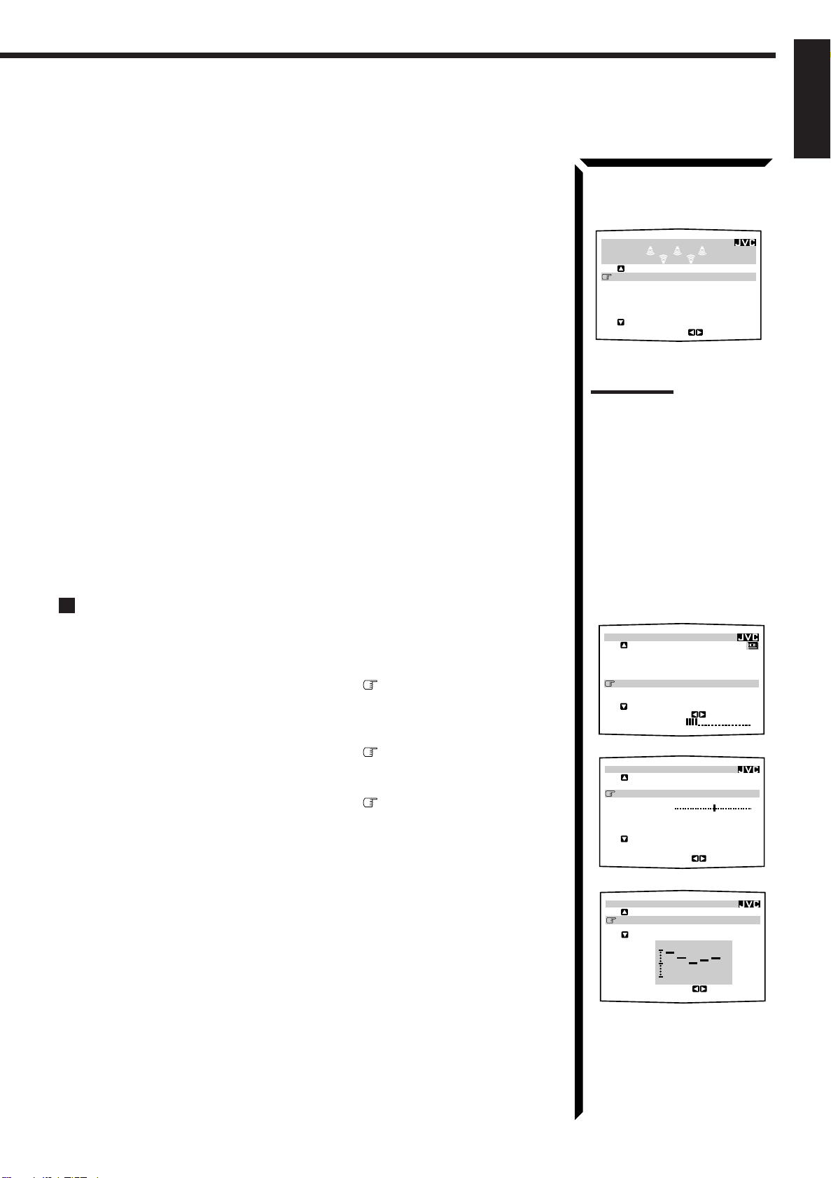
For Dolby Surround Pro Logic:
SURROUND LEVEL
:OPERATE
TEST TONE : OFF
CENTER LEVEL: 0
dB
REAR L LEVEL: 0
dB
REAR R LEVEL: 0dB
CENTER TONE : FLAT
DSP EFFECT : 3
MAIN MENU
SOURCE :VCR1
VISUAL :VCR1
MODE :OFF
SOUND CONTROL
TUNER CONTROL
SETTING
VOLUME : 20
:ENTER
**
**
**
**
**
**
“TEST TONE”: Output a test tone.
“CENTER LEVEL”: Adjust the center speaker output level. **
“REAR L LEVEL”: Adjust the left rear speaker output level. *
“REAR R LEVEL”: Adjust the right rear speaker output level. *
“CENTER TONE”: Select the center tone level. **
For Dolby Digital:
“TEST TONE”: Output a test tone.
“CENTER LEVEL”: Adjust the center speaker output level. **
“REAR L LEVEL”: Adjust the left rear speaker output level. *
“REAR R LEVEL”: Adjust the right rear speaker output level. *
“CENTER TONE”: Select the center tone level. **
For Theater Surround and Digital Theater Surround:
“TEST TONE”: Output a test tone.
“CENTER LEVEL”: Adjust the center speaker output level. **
“REAR L LEVEL”: Adjust the left rear speaker output level. *
“REAR R LEVEL”: Adjust the right rear speaker output level. *
“CENTER TONE”: Select the center tone level. **
“DSP EFFECT”: Select the effect level.*
7. When you finish, press EXIT repeatedly until the menu disappears from the
TV.
English
Example:
SURROUND LEVEL menu
for Theater Surround
Notes:
* Not displayed when “REAR
SPK” is set to “NONE” (see
page 20).
**Not displayed when
“CENTER SPK” is set to
“NONE” (see page 20).
Selecting Your Favorite SEA Mode (Also see page 32)
1. Press any button of ON SCREEN CONTROL % / fi / @ / # once.
The MAIN MENU appears on the TV.
2. Press ON SCREEN CONTROL % / fi to move to “SOUND CONTROL,”
then press @ / #.
The SOUND CONTROL menu appears.
3. Press ON SCREEN CONTROL % / fi to move to “SEA,” then press @ / #.
The SEA menu appears.
4. Press ON SCREEN CONTROL % / fi to move to “SEA MODE.”
5. Press ON SCREEN CONTROL @ / # to select the SEA mode you want.
6. When you finish, press EXIT repeatedly until the menu disappears from the
TV.
MAIN MENU
SOUND CONTROL menu
SOUND CONTROL
SURROUND LEVEL
****
SEA
****
BAL.:CNTR
LOUDNESS : OFF
INPUT ATT : NORMAL
SUBWFR LEVEL: 0
NEXT PAGE
dB
:ENTER
SEA menu
SEA
SEA MODE :ROCK
SEA ADJUST
**
100 10kHz1k
:OPERATE
**
50
Page 56

Using the On-Screen Menus
SETTING 1
SUBWOOFER : NO
FRONT SPK : LARGE
CENTER SPK : SMALL
REAR SPK : LARGE
CNTR DELAY : 3msec
REAR DELAY : 5msec
NEXT PAGE
:ENTER
****
SETTING 2
CROSSOVER :100Hz
LFE ATT. : 0
dB
COMP. : OFF
DIGITAL 1 : DBS
DIGITAL 2 : CD
DIGITAL 3 : MD
PREVIOUS PAGE
:ENTER
****
English
Creating Your Own SEA Mode (Also see page 33)
1. Press any button of ON SCREEN CONTROL % / fi / @ / # once.
The MAIN MENU appears on the TV.
2. Press ON SCREEN CONTROL % / fi to move to “SOUND CONTROL,”
then press @ / #.
The SOUND CONTROL menu appears.
3. Press ON SCREEN CONTROL % / fi to move to “SEA,” then press @ / #.
The SEA menu appears.
4. Press ON SCREEN CONTROL % / fi to move to “SEA ADJUST,” then
press @ / #.
The SEA ADJUST menu appears.
5. Press ON SCREEN CONTROL % / fi / @ / # to adjust the SEA mode as you
want.
@ / # : Select the frequency ranges.
% / fi : Adjust the frequency levels.
6. Press SET to store the setting into the SEA USERMODE.
• If you press EXIT, without pressing SET in this step, you can return to the SEA
menu. (The adjustment you have made is active but not stored.)
7. When you finish, press EXIT repeatedly until the menu disappears from the
TV.
MAIN MENU
MAIN MENU
SOURCE :VCR1
VISUAL :VCR1
MODE :OFF
SOUND CONTROL
**
TUNER CONTROL
**
SETTING
**
VOLUME : 20
:ENTER
SOUND CONTROL menu
SOUND CONTROL
SURROUND LEVEL
****
SEA
****
BAL.:CNTR
LOUDNESS : OFF
INPUT ATT : NORMAL
SUBWFR LEVEL: 0
NEXT PAGE
dB
:ENTER
SEA menu
SEA
SEA MODE :ROCK
SEA ADJUST
**
100 10kHz1k
:OPERATE
SEA ADJUST menu
SEA ADJUST
SEA USERMODE
**
**
**
**
Basic Settings
1. Press any button of ON SCREEN CONTROL % / fi / @ / # once.
The MAIN MENU appears on the TV.
2. Press ON SCREEN CONTROL % / fi to move to “SETTING,” then press
@ / #.
The SETTING 1 or SETTING 2 menu appears.
3. Press ON SCREEN CONTROL % / fi to the setting item you want to adjust.
• To go to the SETTING 2 menu, move to “NEXT PAGE,” then press @ / #.
• To go back to the SETTING 1 menu, move to “PREVIOUS PAGE,” then
press @ / #.
On the SETTING 1 and 2 menus, you can do the following:
“SUBWOOFER”: Set the subwoofer information (See page 19).
“FRONT SPK”: Set the front speaker information (See page 20).
“CENTER SPK”: Set the center speaker information (See page 20).
“REAR SPK”: Set the rear speaker information (See page 20).
“CNTR DELAY”: Adjust the delay time of the center speaker output (See page 21).
“REAR DELAY”: Adjust the delay time of the rear speaker output (See page 21).
“CROSSOVER”: Set the crossover frequency (See page 21).
“LFE ATT.”: Set the low frequency effect attenuator level (See page 22).
“COMP.”: Set the dynamic range compression (See page 22).
“DIGITAL 1/2/3”: Set the digital input terminal (See page 20).
51
100 10kHz1k
SETTING 1 menu
SETTING 2 menu
SET
:MEMORY
Page 57

4. Press ON SCREEN CONTROL @ / # to set (or adjust) the setting item selected
MAIN MENU
SOURCE :ch 1 FM 87.50
MHz
VISUAL :VCR1
MODE :OFF
SOUND CONTROL
TUNER CONTROL
SETTING
VOLUME : 20
:ENTER
**
**
**
**
**
**
in step 3.
5. When you finish, press EXIT repeatedly until the menu disappears from the
TV.
Operating the Tuner
1. Press any button of ON SCREEN CONTROL % / fi / @ / # once.
The MAIN MENU appears on the TV.
2. Press ON SCREEN CONTROL % / fi to move to “TUNER CONTROL,”
then press @ / #.
The TUNER CONTROL menu appears.
3. Press ON SCREEN CONTROL % / fi to move to the item you want to set
or adjust, then press ON SCREEN CONTROL @ / #.
On the TUNER CONTROL menu, you can do the following:
“PRESET CH”: Select a preset channel station. (See page 25)
“BAND”: Select the band. (See page 24)
“FREQUENCY”: Tune in a station manually. (See page 24)
“FM MODE”: Select the FM reception mode. (See page 25) *
“PRESET MEMORY”: See “Storing the Preset Stations” below.
“RDS INFORMATION”: See “Checking the RDS Information.” (See page 54)
MAIN MENU
TUNER CONTROL menu
TUNER CONTROL
PRESET CH : 1
BAND :FM
FREQUENCY : 87.50
FM MODE :AUTO
PRESET MEMORY
****
RDS INFORMATION
****
:OPERATE
English
MHz
4. When you finish, press EXIT repeatedly until the menu disappears from the
TV.
Storing the Preset Stations (Also see page 24)
1. Press any button of ON SCREEN CONTROL % / fi / @ / # once.
The MAIN MENU appears on the TV.
2. Press ON SCREEN CONTROL % / fi to move to “TUNER CONTROL,”
then press @ / #.
The TUNER CONTROL menu appears.
3. Tune into a station on the TUNER CONTROL menu, referring to “Operating
the T uner” above.
4. Press ON SCREEN CONTROL % / fi to move to “PRESET MEMORY,”
then press @ / #.
The PRESET MEMORY menu appears.
5. Press ON SCREEN CONTROL % / fi to move to “PRESET CH”
6. Press ON SCREEN CONTROL @ / # to select a preset station number you
want.
Note:
* Not displayed when an AM
station is selected.
PRESET MEMORY menu
PRESET MEMORY
FM 87.50
PRESET CH : CH 1
PRESET NAME: WABC
MHz
AUTO
:MEMORY
SET
:OPERATE
7. Press SET to store the setting.
8. When you finish, press EXIT repeatedly until the menu disappears from the
TV.
52
Page 58

Using the On-Screen Menus
PRESET MEMORY
FM 87.50
MHz
AUTO
PRESET CH : CH39
PRESET NAME: WABC
:OPERATE
:MEMORY
SET
PRESET MEMORY
SET
:MEMORY
:OPERATE
FM 107.90
MHz
AUTO
PRESET CH : CH39
PRESET NAME: WABC
A B C D E F G H I J K
L M N O P Q R S T U V
W X Y Z
1 2 3 4 5 6 7 8 9 0
SPACE
CANCEL
English
Assigning Names to the Preset Stations (Also see page 26)
1. Press any button of ON SCREEN CONTROL % / fi / @ / # once.
The MAIN MENU appears on the TV.
2. Press ON SCREEN CONTROL % / fi to move to “TUNER CONTROL,”
then press @ / #.
The TUNER CONTROL menu appears.
3. Press ON SCREEN CONTROL % / fi to move to “PRESET CH.”
4. Press ON SCREEN CONTROL @ / # to select a preset station.
5. Press ON SCREEN CONTROL % / fi to move to “PRESET MEMORY,”
then press @ / #.
The PRESET MEMORY menu appears.
6. Press ON SCREEN CONTROL % / fi to move to “PRESET NAME,” then
press SET.
The character entry screen appears.
MAIN MENU
MAIN MENU
SOURCE :ch 1 FM 87.50
VISUAL :VCR1
MODE :OFF
SOUND CONTROL
**
TUNER CONTROL
**
SETTING
**
VOLUME : 20
:ENTER
TUNER CONTROL menu
TUNER CONTROL
PRESET CH :39
BAND :FM
FREQUENCY : 87.50
FM MODE :AUTO
PRESET MEMORY
****
RDS INFORMATION
****
:ENTER
PRESET MEMORY menu
MHz
**
**
**
MHz
7. Press ON SCREEN CONTROL % / fi / @ / # to move in front of a
character you want.
You can also select the following:
SPACE: To enter space CANCEL: To erase the character
: To go back to the previous character position or go to the next character
position
8. Press SET to enter the selected character.
9. Repeat steps 7 and 8 to enter up to four characters.
10.Press ON SCREEN CONTROL % / fi / @ / # to move to “PRESET
NAME,” then press SET to store the setting.
The TUNER CONTROL menu appears again.
11.When you finish, press EXIT repeatedly until the menu disappears from the
TV.
PRESET MEMORY menu:
Character entry screen
PRESET MEMORY
FM 107.90
PRESET CH : CH39
PRESET NAME:
A B C D E F G H I J K
L M N O P Q R S T U V
W X Y Z
1 2 3 4 5 6 7 8 9 0
SPACE
MHz
AUTO
CANCEL
SET
:MEMORY
:OPERATE
53
Page 59

Checking the RDS Information (Also see page 27)
1. Press any button of ON SCREEN CONTROL % / fi / @ / # once.
The MAIN MENU appears on the TV.
2. Press ON SCREEN CONTROL % / fi to move to “TUNER CONTROL,”
then press @ / #.
The TUNER CONTROL menu appears.
RDS INFORMATION menu
RDS INFORMATION
CH29 FM107.90
STATION :FM TOKYO
PROG.TYPE :TRAFFIC
RADIO TEXT:ABCDEFGH
MHz
:RETURN
English
3. Press ON SCREEN CONTROL % / fi to move to “RDS INFORMATION,”
then press @ / #.
The RDS INFORMATION menu appears.
4. When you finish, press EXIT repeatedly until the menu disappears from the TV.
Notes:
• The on-screen display cannot
show accented letters.
• RDS is not available for AM
(MW/LW) broadcasts.
54
Page 60

COMPU LINK Remote Control System
The COMPU LINK remote control system allows you to operate JVC audio components through the remote
sensor on the receiver.
English
To use this remote control system, you need to connect JVC audio components through
the COMPU LINK-3 (SYNCHRO) jacks (see below) in addition to the connections
using cables with RCA pin plugs (see page 9) (and a digital cable if you want — see
page 12).
• Make sure that the AC power cords of these components are unplugged before
connection. Plug the AC power cords only after all connections are complete.
COMPU LINK – 3
(SYNCHRO)
CD player
Cassette deck
or
MD recorder
Turntable
This remote control system allows you to use four functions listed below.
Remote Control through the Remote Sensor on the Receiver
You can control the connected audio components through the remote sensor on the
receiver using this remote control. Aim the remote control directly at the remote sensor
on the receiver. For details, see pages 63 and 64.
Notes:
• If your audio component has
two COMPU LINK-3
(SYNCHRO) jacks, you can
use either one. If it has only
one COMPU LINK-3
(SYNCHRO) jack, connect it
so that it is the last item in the
series of components. (For
example, the turntable or CD
player in the diagram to the
left.)
• To operate the cassette deck
or MD recorder using the
COMPU LINK remote control
system, set the source name
correctly. (See page 18.)
• Refer also to the manuals
supplied with your audio
components.
Automatic Source Selection
When you press the play (
33
3) button on a connected component or on its own remote
33
control, the receiver automatically turns on and changes the source to the component.
On the other hand, if you select a new source on the receiver or the remote control, the
selected component begins playing immediately.
In both cases, the previously selected source continues playing without sound for a few
seconds.
Automatic Power On/Off (Standby): only possible with the COMPU
LINK-3 connection
Both the CD player and cassette deck (or MD recorder) turn on and off (standby) along
with the receiver.
When you turn on the receiver, the CD player or cassette deck (or MD recorder) will
turn on automatically, depending on which component has been previously selected.
When you turn off the receiver, both the CD player and cassette deck (or MD recorder)
will turn off (standby).
Synchronized Recording
Synchronized recording means the cassette deck (or MD recorder) starts recording as
soon as a CD or a record begins playing.
To use synchronized recording, follow these steps:
1. Put a tape in the cassette deck (or an MD in the MD recorder), and a disc in the
CD player (or a record on the turntable).
2. Press the record (
¶¶
¶) button and the pause (
¶¶
88
8) button on the cassette deck (or
88
MD recorder) at the same time.
This puts the cassette deck (or MD recorder) into recording pause.
If you do not press the record (¶) button and pause (8) button at the same time, the
synchronized recording feature will not operate.
3. Press the play (
33
3) button on the CD player or on the turntable.
33
The source changes on the receiver, and as soon as play starts, the cassette deck (or
MD recorder) starts recording. When the play ends, the cassette deck (or MD
recorder) enters recording pause, and stops about 4 seconds later.
Notes:
• During synchronized
recording, the selected source
cannot be changed.
• If your CD player is playing in
program mode, a 4-second
blank is recorded between
tracks so that the music scan
feature of your cassette deck
can be used on the recorded
tape.
• If the power of any component
is shut off during synchronized
recording, the COMPU LINK
remote control system may
not operate properly. In this
case, you must start again
from the beginning.
55
Page 61

TEXT COMPU LINK Remote Control System
The TEXT COMPU LINK remote control system has been newly developed to deal with the disc information
recorded in the CD Text* and MDs. Using these information in the discs, you can operate the CD player or
MD recorder equipped with the TEXT COMPU LINK remote control system through the receiver.
English
CONNECTIONS:
To use this remote control system, you need to connect the CD player and/or MD
recorder you want to operate, following the procedures below.
1. If you have already plugged your CD player, MD recorder, and this receiver
into the AC outlets, unplug their AC power cords first.
2. Connect your CD player, MD recorder, and this receiver as follows, through the
COMPU LINK-3 (SYNCHRO) jacks and TEXT COMPU LINK jacks.
1) COMPU LINK-3 (SYNCHRO) jacks: Use the cables with the monaural mini-
plugs (not supplied with this receiver)
CD player
MD recorder
2) TEXT COMPU LINK jacks: Use the cables with the stereo mini-plugs (not
supplied with this receiver)
CD player
MD recorder
IMPORTANT:
Set the Master/Slave Selector on the rear to “1(MASTER UNIT).”
• “2(SLAVE UNIT)” is just for the serviceman’s use. The TEXT
COMPU LINK remote control system does not function with
the selector set to “2(SLAVE UNIT).”
3. Connect your CD player, MD recorder and this receiver, using the cables with
RCA pin plugs (see page 9) (and a digital cable if you want — see page 12).
COMPU LINK – 3
(SYNCHRO)
TEXT
COMPU LINK
1(MASTER UNIT)
2(SLAVE UNIT)
*What is a CD Text?
In a CD Text, some information
about the disc (its disc title,
performer, composer, arranger,
etc.) is recorded.
Notes:
• If your audio component has
two COMPU LINK-3
(SYNCHRO) jacks, you can
use either one. If it has only
one COMPU LINK-3
(SYNCHRO) jack, connect it
so that it is the last item in the
series of components. (For
example, the CD player in the
diagram to the left.)
• If your audio component has
two TEXT COMPU LINK
jacks, you can use either one.
If it has only one TEXT
COMPU LINK jack, connect it
so that it is the last item in the
series of components. (For
example, the CD player in the
diagram to the left.)
• Refer also to the manuals
supplied with your CD player
or MD recorder.
4. Plug the AC power cords of these components above into the AC outlets.
5. When turning on these components for the first time, turn on the connected
components first, then turn on this receiver.
FUNCTIONS:
This remote control system allows you to use the functions listed below.
Displaying the Disc Information on the TV screen
Disc information such as its performer and disc title (and track titles only when a CD
Text is selected) is shown on the TV screen.
Disc Search: Only for CD Player
This remote control system can allow you to search discs by the performer, disc title,
and music genre.
With this disc search, you can easily find the disc you want to play.
Additional Functions:
• If your CD player has the User File function, you can select a disc from the groups.
* A “user file” is a group of the discs you make as you like on the CD player.
• If your CD player has the disc memory function, you can input the performer, disc
title, and music genre about these normal audio CDs on the TV screen.
Note:
If you turn on the receiver before
turning on the other components
after connecting components,
the TEXT COMPU LINK remote
control system does not work
correctly.
If this happens:
1.Turn off the all components
including this receiver.
2.Turn on the connected
components.
3.Turn on this receiver.
56
Page 62

TEXT COMPU LINK Remote Control System
English
OPERATIONS
To use this remote control system, you need to connect the TV to the MONITOR OUT
jack on the rear panel (see page 10), and set the TV’s input mode to the proper position
to which the receiver is connected. Make sure you have connected the CD
player or MD recorder equipped with the TEXT COMPU LINK remote
control system. If not, you cannot use the following functions.
Showing the Disc Information on the TV Screen
1. Press any button of ON SCREEN CONTROL % / fi / @ / # once.
The MAIN MENU appears on the TV.
2. Press ON SCREEN CONTROL % / fi to move to “SOURCE.”
3. Press ON SCREEN CONTROL @ / # to select “CD” or “MD.”
4. Press ON SCREEN CONTROL % / fi to move to “VISUAL.”
5. Press ON SCREEN CONTROL @ / # to select “OSD,” then press EXIT.
The Disc Information screen appears on the TV.
Notes:
• The on-screen display will not
appear about one minute after
the power is turned on.
• The on-screen display will
disappear in the following
case:
– if no operation is done for
about 10 minutes.
– if you do any operation
other than explained in this
section.
• To control the MD recorder
using the TEXT COMPU LINK
remote control system, you
have to change the source
name shown on the display
from “TAPE” to “MD.” (See
page 18.)
• The number of characters to
show the disc information
such as the disc title or track
title is limited to 32. So if the
disc title, for example, is
longer than 32 characters,
only the first 32 characters are
shown.
• Some special characters such
as accented letters cannot be
displayed correctly.
1 Source name: CD or MD
2 Select
3 Track numbers and track titles.
• The current playing (selected) track is indicated in yellow.
• When you move
4 Select this (move
(see page 58).
5 Select this (move in front), then press SET to go to the USER FILE screen (see
page 60).
6 Select this (move
page 61).
7 Disc information such as the disc title, performer, and music genre.
When this is selected (
@ / #. Each time you press the button, disc information (see the note) changes.
8 Select or , then press SET to change the track.
9 Usable buttons and their functions for the current selection.
Indication here will be changed what is currently selected ( in front) on the
screen.
or , then press SET to change the disc.
to a track number, you can change the track information by
pressing @ / #. Each time you press the button, track information alternates
between its track title and its performer. (You can also start playing the track by
pressing SET.)
in front), then press SET to go to the DISC SEARCH screen
in front), then press SET to go to the TITLE INPUT screen (see
in front) , you can change the disc information by pressing
6. When you finish, press EXIT repeatedly until the MAIN MENU appears on
the TV.
To exit from the MAIN MENU:
1) Press ON SCREEN CONTROL % / fi to move to “VISUAL.”
2) Press ON SCREEN CONTROL @ / # to select any one other than “OSD,” then
press EXIT.
Note on
The following information will
appear on the display:
• Disc title
• Performer
• Genre
• Song writer
• Composer
• Arranger
• Message
Only recorded information will
be shown. If there is no data,
“NO DA T A” will appear.
Note on
For example, the SET button will
be used to start play (PLAY), to
go to the next screen (ENTER),
and to determine the selection
(ENTER).
7
9
57
Page 63

Searching a Disc (Only for the CD player)
English
Search a disc by its performer:
1. Display the disc information screen by following the procedure on page 57.
2. Press ON SCREEN CONTROL % / fi to move to “SEARCH,” then
press SET.
The DISC SEARCH screen appears on the TV.
3. Press ON SCREEN CONTROL % / fi to move to “PERFORMER”, then
press SET.
The PERFORMER SEARCH screen appears.
4. Press ON SCREEN CONTROL % / fi / @ / # to move in front of the
first character of the performer you want to search, then press SET.
To correct the incorrect entry, press ON SCREEN CONTROL % / fi to
move in front of the correct character, then press SET.
To erase the incorrect entry, press ON SCREEN CONTROL % / fi to move to
CANCEL, then press SET.
5. Press SET again.
Disc search starts, then the SEARCH RESULT screen, showing the performers,
appears.
6. On the SEARCH RESULT screen, you can do the following:
• Changing the indication of the disc information: Press ON SCREEN
CONTROL % / fi to move to a searched disc, then press @ / #. Each time you
press @ / #, the disc information alternates between its performer and its disc
title.
• Going to the Disc Information screen (see page 57): Press ON SCREEN
CONTROL % / fi to move to a searched disc, then press SET.
• Showing unseen disc information (if more than 5 discs are listed as a result of
the search): Press ON SCREEN CONTROL % / fi to move to (or ),
then press SET.
• Going back to the PERFORMER SEARCH screen: Press EXIT.
DISC SEARCH screen
PERFORMER SEARCH
screen
SEARCH RESULT screen
Note
Symbols such as @, # or $
cannot be available for search.
Search a disc by its disc title:
1. Display the disc information screen by following the procedure on page 57.
2. Press ON SCREEN CONTROL % / fi to move to “SEARCH,” then
press SET.
The DISC SEARCH screen appears on the TV.
3. Press ON SCREEN CONTROL % / fi to move “DISC TITLE”, then
press SET.
The DISC TITLE SEARCH screen appears.
4. Press ON SCREEN CONTROL % / fi / @ / # to move in front of the
first character of the disc title you want to search, then press SET.
To correct the incorrect entry, press ON SCREEN CONTROL % / fi move in
front of the correct character, then press SET.
To erase the incorrect entry, press ON SCREEN CONTROL % / fi move to
CANCEL, then press SET.
Continued to the next page.
DISC SEARCH screen
DISC TITLE SEARCH screen
58
Page 64

TEXT COMPU LINK Remote Control System
English
5. Press SET again.
Disc search starts, then the SEARCH RESULT screen, showing the disc titles,
appears.
6. On the SEARCH RESULT screen, you can do the following:
• Changing the indication of the disc information: Press ON SCREEN
CONTROL % / fi to move to a searched disc, then press @ / #. Each time you
press @ / #, the disc information alternates between its disc title and its
performer.
• Going to the Disc Information screen (see page 57): Press ON SCREEN
CONTROL % / fi to move to a searched disc, then press SET.
• Showing unseen disc information (if more than 5 discs are listed as a result of
the search): Press ON SCREEN CONTROL % / fi to move to (or ),
then press SET.
• Going back to the DISC TITLE SEARCH screen: Press EXIT.
Search a disc by its genre:
1. Display the disc information screen by following the procedure on page 57.
SEARCH RESULT screen
Note
Symbols such as @, # or $
cannot be available for search.
2. Press ON SCREEN CONTROL % / fi to move to “SEARCH,” then
press SET.
The DISC SEARCH screen appears on the TV.
3. Press ON SCREEN CONTROL % / fi to move to “GENRE”, then press
SET.
The GENRE SEARCH screen appears.
4. Press ON SCREEN CONTROL % / fi to move to the genre you want to
search, then press SET.
To show the unseen genres, press ON SCREEN CONTROL % / fi until they appear.
Disc search starts, then the SEARCH RESULT screen, showing the disc titles,
appears.
5. On the SEARCH RESULT screen, you can do the following:
• Changing the indication of the disc information: Press ON SCREEN
CONTROL % / fi to move to a searched disc, then press @ / #. Each time you
press @ / #, the disc information alternates between its disc title and its
performer.
• Going to the Disc Information screen (see page 57): Press ON SCREEN
CONTROL % / fi to move to a searched disc, then press SET.
• Showing unseen disc information (if more than 5 discs are listed as a result of
the search): Press ON SCREEN CONTROL % / fi to move to (or ),
then press SET.
• Going back to the GENRE SEARCH screen: Press EXIT.
GENRE SEARCH screen
SEARCH RESULT screen
59
Page 65

Using the User File (Only for the CD Player with the User
File Function)
You can use the User File function through this receiver.
For the User File function, refer to the manual supplied with your CD player.
Using your own User Files:
1. Display the disc information screen by following the procedure on page 57.
English
2. Press ON SCREEN CONTROL % / fi to move to “USER FILE,” then
press SET.
The USER FILE screen appears on the TV.
To show the unseen user files, press ON SCREEN CONTROL % / fi until they
appear.
3. Press ON SCREEN CONTROL % / fi to move to the User File you want,
then press SET.
The selected User File screen appears on the TV.
The disc information shown will be the disc title. (If no disc title information is
recorded for the discs, only the disc numbers will be shown.)
4. On this selected User File screen, you can do the following:
• Changing the indication of the disc information: Press ON SCREEN
CONTROL % / fi to move to a disc, then press @ / #. Each time you press @
/ #, the disc information alternates between its disc title and its performer.
• Starting a disc play: Press ON SCREEN CONTROL % / fi to move to a disc,
then press SET.
• Showing unseen disc information (if more than 5 discs are listed): Press ON
SCREEN CONTROL % / fi to move to (or ) and press SET.
• Going back to the USER FILE screen: Press EXIT.
USER FILE screen
User File 1 screen
60
Page 66

TEXT COMPU LINK Remote Control System
English
Entering the Disc Information
For the CD Player with the disc memory function:
You can use the disc memory function through this receiver.
The disc information (its performer, disc title, and its music genre) of normal audio CDs
will be stored into the memory built in the CD player.
For the disc memory function, refer to the manual supplied with your CD player.
• The performer, disc title, and music genre information are usually recorded in a CD
Text. However, if a CD Text has no genre information recorded in the disc itself, you
can input its music genre by yourself.
Note: You can enter the TITLE INPUT screens for a CD Text and input its titles.
Howev er, you cannot store the titles you have input for a CD Text.
Example: Entering the following information for Disc 1
Performer: “MICHEAL”
Disc title: “MY FAVORITE”
1. Display the disc information screen by following the procedure on page 57.
TITLE INPUT: PERFORMER
screen
2. Press ON SCREEN CONTROL % / fi to move to “TITLE INPUT,” then
press SET.
The TITLE INPUT: PERFORMER screen appears on the TV.
3. Press ON SCREEN CONTROL % / fi / @ / # to move in front of a
character you want, then press SET to enter the character.
• If the current CD is a CD Text, go to step 5 without entering the performer.
To use the lower case letters, press ON SCREEN CONTROL % / fi / @ / # to
move to
SHIFT
, then press SET.
To use the upper case letters again, press ON SCREEN CONTROL % / fi / @ / #
to move to
SHIFT
, then press SET.
4. Repeat step 3 until you finish putting a name (up to 32 characters) to this
User File.
To insert a space, press ON SCREEN CONTROL % / fi / @ / # to move to
SPACE
, then press SET.
To correct an incorrect character:
1) Press ON SCREEN CONTROL % / fi / @ / # to move to or , then
press SET until the incorrect character is selected.
2) Press ON SCREEN CONTROL % / fi / @ / # to move to CANCEL, then
press SET to erase the character.
3) Press ON SCREEN CONTROL % / fi / @ / # to move in front of an correct
character, then press SET to enter a correct character.
TITLE INPUT: DISC TITLE
screen
5. Press ON SCREEN CONTROL % / fi / @ / # to move to “DISC1:
MICHEAL (in this example),” then press SET.
The TITLE INPUT: DISC TITLE screen appears.
6. Enter the disc title, referring to steps 3 and 4.
• If the current CD is a CD Text, go to the next step without entering the disc
title.
61
Page 67

7. Press ON SCREEN CONTROL % / fi / @ / # to move to “DISC1: MY
SOURCE: MD
****
:BACK
:ENTER
SET
EXIT
DISC TITLE INPUT
MD :GOOD MUSIC
A B C D E F G H I J K
L M N O P Q R S T U V
W X Y Z – ! " # $ % &
+ , . – / : ; < = > ?
1 2 3 4 5 6 7 8 9 0 @
SPACE SHIFT
CANCEL
FAVORITE (in this example),” then press SET.
The TITLE INPUT: DISC 1 GENRE screen appears.
8. Press ON SCREEN CONTROL % / fi to move to the genre you want,
then press SET.
The Disc Information screen appears again.
To show the unseen genres, press ON SCREEN CONTROL % / fi until they appear.
For the MD recorder:
You can write the disc information (disc title and song titles) into the disc. You can only
write the song title for the song currently selected.
• If you have the CD-MD combination deck, you can also enter the disc information
(its performer, disc title, and its music genre) of normal audio CDs into the memory
built in the CD-MD combination deck. (To do this, follow the procedure on page
61.)
1. Display the disc information screen by following the procedure on page 57.
English
TITLE INPUT: DISC 1 GENRE
screen
Disc Information screen
2. Press ON SCREEN CONTROL % / fi to move to “TITLE INPUT,” then
press SET.
The DISC TITLE INPUT screen appears on the TV.
3. Enter the disc title, referring to steps 3 and 4 on page 61.
• You can enter up to 32 character for the disc title.
4. Press ON SCREEN CONTROL % / fi / @ / # to move to the disc title
you have just entered, then press SET.
The disc title is stored into the memory, and the SONG TITLE INPUT screen for the
currently selected song appears.
• You can enter a song title for the song currently selected (indicated in yellow on the
TV screen
).
5. Enter the song title, referring to steps 3 and 4 on page 61.
• You can enter up to 32 character for the song title.
6. Press ON SCREEN CONTROL % / fi / @ / # to move to the song title
you have just entered, then press SET.
The song title is stored into the memory, and the Disc Information screen appears
again.
DISC TITLE INPUT screen
62
Page 68

Operating JVC’s Audio/Video Components
You can operate JVC’s audio and video components with this receiver’s remote control, since control
signals for JVC components are preset in the remote control.
English
IMPORTANT:
To operate JVC’s audio components using this remote control:
• You need to connect JVC audio components through the COMPU LINK-3
(SYNCHRO) jacks (see page 55) in addition to the connections using cables
with RCA pin plugs (see page 9) or using digital cables (see page 12).
• Aim the remote control directly at the remote sensor on the receiver.
Tuner
After pressing FM/AM (with the remote control mode selector
set to “AUDIO/TV/VCR”), you can perform the following
operations:
FM/AM: Alternates between FM and AM (MW/
LW).
1 – 10, +10: Selects a preset channel number directly.
For channel number 5, press 5. For
channel number 15, press +10, then 5.
For channel number 20, press +10, then
10.
PTY SEARCH: Searches for a program by PTY codes.
PTY +/–: Selects the PTY codes.
DISPLAY MODE: Shows the RDS signals.
RM-SR884RU REMOTE CONTROL
TV/CATV
/DBS
DVD VCR1 VIDEOVCR2
CD
TV/DBS
SURROUND
MODE
SOUND
CONTROL
CD
DISC
AUDIO/TV
/VCR
CATV
/DBS
MUTE
PTY –
4 / REW
FM MODE/MUTE: Changes the FM reception mode.
Sound control section (Amplifier)
TV/VIDEO
SET
You can always perform the following operations (with the
remote control mode selector set to “AUDIO/TV/VCR”):
SURROUND MODE: Changes the DSP modes.
O
After pressing SOUND CONTROL (with the remote control
mode selector set to “AUDIO/TV/VCR”), you can perform the
following operations:
SEA MODE: Changes the SEA modes.
SUBWOOFER +/–: Adjusts the subwoofer output level.
CNTR +/–: Adjusts the center speaker output
level.
REAR•L +/–: Adjusts the left rear speaker output
level.
REAR•R +/–: Adjusts the right rear speaker output level.
EFFECT: Selects the effect level.
TEST: Turns on or off the test tone output.
CNTR TONE: Selects the center tone.
VCR1
TAPE/MD FM/AMPHONO
CNTR TONE
TEST
EFFECT
SEA MODE
10
RETURN
VOLUME
CHANNEL
PTY SEARCH
PLAY
STOP
REC
DISPLAY MODE
CONTROL
VCR1 TAPE
N
S
C
R
E
E
ANALOG
AUDIO
/DIGITAL
CNTR
213
REAR L
ENTER
546
REAR R
87/P 9
SUBWOOFER
+10
0
FM MODE/MUTE
100+
PTY +
FF / ¢
PAUSE
TV VOLUME
EXIT
L
O
R
T
N
O
C
N
Notes:
• If you use the buttons on the
front panel or the menu
function to choose a source,
the remote control will not
operate that source. To
operate a source with the
remote control, the source
must be selected using
buttons on the remote control.
• Check to see if its remote
control mode selector is set to
the correct position. To
MENU
operate audio system, TVs,
and VCRs, set it to “AUDIO/
TV/VCR.”
• Refer also to the manuals
supplied with your
components.
Note:
After adjusting sounds, press
the corresponding source
selecting button or CD DISC to
operate your target source by
using 10 keys; otherwise, 10
keys cannot be used for
operating your target source.
CD player
After pressing CD (with the remote control mode selector set to “AUDIO/TV/VCR”),
you can perform the following operations on a CD player:
PLAY: Starts playing.
44
4: Returns to the beginning of the current (or previous) track.
44
¢¢
¢: Skips to the beginning of the next track.
¢¢
STOP: Stops playing.
PAUSE: Pauses playing. To release it, press PLAY.
1 – 10, +10: Selects a track number directly.
For track number 5, press 5. For track number 15, press +10, then 5. For
track number 20, press +10, then 10. For track number 30, press +10,
+10, then 10.
63
Page 69

CD player-changer
After pressing CD DISC (with the remote control mode selector
set to “AUDIO/TV/VCR”), you can perform the following
operations on the CD player-changer:
PLAY: Starts playing.
44
4: Returns to the beginning of the current (or
44
previous) track.
¢¢
¢: Skips to the beginning of the next track.
¢¢
STOP: Stops playing.
PAUSE: Pauses playing. To release it, press the PLAY
button.
1 – 6, 7/P: Select the number of a disc installed in a CD
player-changer.
After pressing CD (with the remote control mode selector set to
“AUDIO/TV/VCR”), you can perform the following operations
on the CD player-changer:
1 – 10, +10: Selects a track number directly.
For track number 5, press 5. For track number
15, press +10, then 5. For track number 20,
press +10, then 10. For track number 30, press
+10, +10, then 10.
RM-SR884RU REMOTE CONTROL
VCR1
TV/CATV
/DBS
DVD VCR1 VIDEOVCR2
CD
TAPE/MD FM/AMPHONO
CNTR TONE
TV/DBS
SURROUND
TEST
ENTER
MODE
SOUND
EFFECT
CONTROL
CD
SEA MODE
DISC
10
FM MODE/MUTE
RETURN
AUDIO/TV
/VCR
VOLUME
CATV
/DBS
CHANNEL
MUTE
PTY SEARCH
PLAY
PTY –
4 / REW
STOP
REC
DISPLAY MODE
TV/VIDEO
CONTROL
VCR1 TAPE
SET
O
N
S
C
R
E
E
N
ANALOG
AUDIO
/DIGITAL
CNTR
MENU
213
REAR L
546
REAR R
87/P 9
SUBWOOFER
+10
0
100+
PTY +
FF / ¢
PAUSE
TV VOLUME
EXIT
L
O
R
T
N
O
C
English
Turntable
After pressing PHONO (with the remote control mode selector
set to “AUDIO/TV/VCR”), you can perform the following
operations on the turntable:
PLAY: Starts playing.
STOP: Stops playing.
Cassette deck
After pressing TAPE/MD or TAPE CONTROL (with the
remote control mode selector set to “AUDIO/TV/VCR”), you
can perform the following operations on the cassette deck:
PLAY: Starts playing.
REW: Fast winds the tape from right to left.
FF: Fast winds the tape from left to right.
STOP: Stops operations.
PAUSE: Pauses playing or recording temporarily. To release it, press the PLAY button.
¶¶
REC
¶: Press this button with the PLAY button to start recording.
¶¶
Press this button with the PAUSE button to enter recording pause.
MD recorder
After pressing TAPE/MD or TAPE CONTROL (with the remote control mode selector
set to “AUDIO/TV/VCR”), you can perform the following operations on the MD
recorder:
PLAY: Starts playing.
44
4: Returns to the beginning of the current (or previous) track.
44
¢¢
¢: Skips to the beginning of the next track.
¢¢
STOP: Stops playing.
PAUSE: Pauses playing. To release it, press the PLAY button.
¶¶
REC
¶: Press this button with the PLAY button to start recording.
¶¶
Press this button with the PAUSE button to enter recording pause.
Notes:
• To operate the cassette deck
or MD recorder using the
COMPU LINK remote control
system, set the source name
correctly. (See page 18.)
• You can use either the TAPE/
MD button or the TAPE
CONTROL button to activate
the buttons listed to the left. If
you press TAPE/MD, the
playing source also changes.
On the other hand, if you
press TAPE CONTROL, the
playing source does not
change.
64
Page 70

Operating JVC’s Audio/Video Components
English
IMPORTANT:
To operate JVC’s video components using this remote control:
• Aim the remote control directly at the remote sensor on the VCR, DVD player or
TV, not on the receiver.
VCR1 (the VCR connected to the VCR1 jacks)
You can always perform the following operations (with the
remote control mode selector set to “AUDIO/TV/VCR”):
VCR1 : Turns on or off the VCR1.
After pressing VCR1 or VCR1 CONTROL (with the remote
control mode selector set to “AUDIO/TV/VCR”), you can
perform the following operations on the VCR:
PLAY: Starts playing.
REW: Rewinds a tape.
FF: Fast winds a tape.
STOP: Stops operations.
PAUSE: Pauses playing or recording temporarily. To
release it, press the PLAY button.
¶¶
REC
¶: Press this button with the PLAY button to
¶¶
start recording.
Press this button with the PAUSE button to
enter recording pause.
CHANNEL +/–: Changes the channels on the VCR.
1 – 9, 0: Selects the channels on the VCR.
For channel 5, press 5.
For channel 10, press 1, then 0.
RM-SR884RU REMOTE CONTROL
VCR1
TV/CATV
/DBS
DVD VCR1 VIDEOVCR2
CD
TAPE/MD FM/AMPHONO
CNTR TONE
TV/DBS
SURROUND
TEST
ENTER
MODE
SOUND
EFFECT
CONTROL
CD
SEA MODE
DISC
10
FM MODE/MUTE
RETURN
AUDIO/TV
/VCR
VOLUME
CATV
/DBS
CHANNEL
MUTE
PTY SEARCH
PLAY
PTY –
4 / REW
STOP
REC
DISPLAY MODE
TV/VIDEO
CONTROL
VCR1 TAPE
SET
O
N
S
C
R
E
E
N
ANALOG
AUDIO
/DIGITAL
CNTR
213
REAR L
546
REAR R
87/P 9
SUBWOOFER
+10
0
100+
PTY +
FF / ¢
PAUSE
TV VOLUME
EXIT
L
O
R
T
N
O
C
Notes:
• Some JVC VCRs can accept
two types of the control
signals — code “A” and “B.”
MENU
Before using this remote
control, make sure that the
remote control code of the
VCR1 is set to code “A.”
• You can use either the VCR1
button or the VCR1
CONTROL button to activate
the buttons listed to the left. If
you press VCR1, the playing
source also changes. On the
other hand, if you press VCR1
CONTROL, the playing source
does not change.
DVD player
After pressing DVD (with the remote control mode selector set
to “AUDIO/TV/VCR”), you can perform the following
operations on a DVD player:
PLAY: Starts playing.
44
4: Returns to the beginning of the current (or
44
previous) track.
¢¢
¢: Skips to the beginning of the next track.
¢¢
STOP: Stops playing.
PAUSE: Stops playing temporarily. To release it, press the
PLAY button.
After pressing DVD (with the
remote control mode selector
set to the “AUDIO/TV/VCR”
position), these buttons can
be used for the DVD menu
operations.
CNTR
CNTR TONE
TEST
EFFECT
ENTER
MENU
213
REAR L
546
REAR R
87/P 9
Note:
For detailed menu operations,
refer to the instructions
supplied with the discs or the
DVD player.
65
Page 71

TV
You can always perform the following operations (with the
remote control mode selector set to “AUDIO/TV/VCR”):
TV/CATV/DBS : Turns on or off the TV.
TV VOLUME +/–: Adjusts the volume.
TV/VIDEO: Sets the input mode (either TV or
VIDEO).
After pressing TV/DBS (with the remote control mode selector
set to “AUDIO/TV/VCR”), you can perform the following
operations on a TV:
CHANNEL +/–: Changes the channels.
1 – 9, 0, 100+: Selects the channels.
RETURN: Alternates between the previously
selected channel and the current channel.
RM-SR884RU REMOTE CONTROL
VCR1
TV/CATV
/DBS
DVD VCR1 VIDEOVCR2
CD
TAPE/MD FM/AMPHONO
CNTR TONE
TV/DBS
SURROUND
TEST
ENTER
MODE
SOUND
EFFECT
CONTROL
CD
SEA MODE
DISC
10
FM MODE/MUTE
RETURN
AUDIO/TV
/VCR
VOLUME
CATV
/DBS
CHANNEL
MUTE
PTY SEARCH
PLAY
PTY –
4 / REW
STOP
REC
DISPLAY MODE
TV/VIDEO
CONTROL
VCR1 TAPE
SET
ANALOG
AUDIO
/DIGITAL
CNTR
MENU
213
REAR L
546
REAR R
87/P 9
SUBWOOFER
+10
0
100+
PTY +
FF / ¢
PAUSE
TV VOLUME
EXIT
English
O
N
S
L
O
R
C
T
R
N
E
O
E
C
N
66
Page 72

Operating Other Manufactures’ Components
English
This remote control supplied with the receiver can transmit control signals for other
manufacturers’ VCRs, TVs, CATV converters and DBS tuners. By changing the
transmittable signals from preset ones to the other manufacturers’, you can operate the
other manufacturer’s components using this remote control.
When operating the other manufacturers’ components, refer also to the manuals
supplied with them.
To operate these components with the remote control, first you need to set the
manufacturer’s code each for the VCR, TV, CATV converter, and DBS tuner.
IMPORTANT:
AUDIO/TV
/VCR
CATV
/DBS
When using the Remote Control, check to see if its remote control
mode selector is set to the correct position:
To operate an audio system, TV, and VCR, set it to “AUDIO/TV/
VCR.”
To operate a CATV converter and DBS tuner, set it to “CATV/
DBS.”
To change the transmittable signals for operating another
manufacturer’s TV
1. Set the remote control mode selector to “AUDIO/TV/
VCR.”
2. Press and hold TV/CATV/DBS .
3. Press TV/DBS.
4. Enter the manufacturer’s code (three digits) using
buttons 1 – 9, and 0.
See the lists on pages 70 and 71 to find the code.
5. Release TV/CA TV/DBS .
The following buttons can be used for operating the TV
(with the remote control mode selector set to “AUDIO/TV/
VCR”):
TV/CATV/DBS : Turns on and off TV.
TV VOLUME +/–: Adjusts the volume.
TV/VIDEO: Sets the input mode (either TV or
VIDEO).
After pressing TV/DBS (with the remote control mode
selector set to “AUDIO/TV/VCR”), you can perform the
following operations on the TV:
CHANNEL +/–: Changes the channels.
1 – 10, 0, 100+(+10): Selects the TV channels.
100+(+10) button will function as the
ENTER button if your TV requires
pressing ENTER after selecting a
channel number.
RM-SR884RU REMOTE CONTROL
VCR1
TV/CATV
/DBS
DVD VCR1 VIDEOVCR2
CD
TAPE/MD FM/AMPHONO
CNTR TONE
TV/DBS
SURROUND
TEST
ENTER
MODE
SOUND
EFFECT
CONTROL
CD
SEA MODE
DISC
10
FM MODE/MUTE
RETURN
AUDIO/TV
/VCR
VOLUME
CATV
/DBS
CHANNEL
MUTE
PTY SEARCH
PLAY
PTY –
4 / REW
STOP
REC
DISPLAY MODE
TV/VIDEO
CONTROL
VCR1 TAPE
SET
O
N
S
C
R
E
E
N
ANALOG
/DIGITAL
213
546
87/P 9
SUBWOOFER
0
TV VOLUME
O
C
REAR L
REAR R
FF / ¢
N
AUDIO
CNTR
MENU
+10
100+
PTY +
PAUSE
EXIT
L
O
R
T
Note:
Refer also to the manual
supplied with your TV.
6. Try to operate your TV by pressing TV/CATV/DBS .
When your TV turns on or off, you have entered the correct code.
7. If there are more than one code listed for your brand of TV, try each one until
the correct one is entered.
67
Page 73

To change the transmittable signals for operating a CATV
converter or DBS tuner
1. Set the remote control mode selector to “CATV/DBS.”
2. Press and hold TV/CATV/DBS .
3. Press TV/DBS.
4. Enter the manufacturer’s code (three digits) using
buttons 1 – 9, and 0.
See the lists on page 72 to find the code.
5. Release TV/CA TV/DBS .
After setting the remote control mode selector to “CATV/
DBS,” you can perform the following operations on the
CATV converter or on the DBS tuner:
TV/CATV/DBS : Turns on and off the CATV
converter or DBS tuner.
CHANNEL +/–: Changes the channels.
1 – 10, 0, 100+(+10): Selects the channels.
100+(+10) button will function
as the ENTER button if your
CATV converter or DBS tuner
requires pressing ENTER after
selecting a channel number.
RM-SR884RU REMOTE CONTROL
VCR1
TV/CATV
/DBS
DVD VCR1 VIDEOVCR2
CD
TAPE/MD FM/AMPHONO
CNTR TONE
TV/DBS
SURROUND
TEST
ENTER
MODE
SOUND
EFFECT
CONTROL
CD
SEA MODE
DISC
10
FM MODE/MUTE
RETURN
AUDIO/TV
/VCR
VOLUME
CATV
/DBS
CHANNEL
MUTE
PTY SEARCH
PLAY
PTY –
4 / REW
STOP
REC
DISPLAY MODE
TV/VIDEO
CONTROL
VCR1 TAPE
SET
O
N
S
C
R
E
E
N
ANALOG
/DIGITAL
C
AUDIO
CNTR
MENU
213
REAR L
546
REAR R
87/P 9
SUBWOOFER
+10
0
100+
PTY +
FF / ¢
PAUSE
TV VOLUME
EXIT
L
O
R
T
N
O
English
Note:
Refer also to the manual
supplied with your CA TV
converter or DBS tuner.
6. Try to operate your CATV converter or DBS tuner by
pressing TV/CATV/DBS .
When your CATV converter or DBS tuner turns on or off, you have entered the
correct code.
7. If there are more than one code listed for your brand of CATV converter or
DBS tuner, try each one until the correct one is entered.
68
Page 74

Operating Other Manufactures’ Components
English
To change the transmittable signals for operating another
manufacturer’s VCR
1. Set the remote control mode selector to “AUDIO/TV/
VCR.”
2. Press and hold VCR1 .
3. Press VCR1.
4. Enter the manufacturer’s code (three digits) using
buttons 1 – 9, and 0.
See the lists on pages 72 and 73 to find the code.
5. Release VCR1 .
The following buttons can be used for operating the VCR
(with the remote control mode selector set to “AUDIO/TV/
VCR”):
VCR1 : Turns on and off VCR.
After pressing VCR1 or VCR1 CONTROL (with the remote
control mode selector set to “AUDIO/TV/VCR”), you can
perform the following operations on the VCR:
CHANNEL +/–: Changes the channels on the VCR.
1 – 10, 0, 100+(+10): Selects the channels on the VCR.
100+(+10) button will function as
the ENTER button if your VCR
requires pressing ENTER after
selecting a channel number.
PLAY: Starts playback.
STOP: Stops operations.
PAUSE: Pauses.
REW: Rewinds a tape.
FF: Fast winds a tape.
¶¶
REC
¶: Starts recording or enters recording pause.
¶¶
RM-SR884RU REMOTE CONTROL
VCR1
TV/CATV
/DBS
DVD VCR1 VIDEOVCR2
CD
TAPE/MD FM/AMPHONO
CNTR TONE
TV/DBS
SURROUND
TEST
ENTER
MODE
SOUND
EFFECT
CONTROL
CD
SEA MODE
DISC
10
FM MODE/MUTE
RETURN
AUDIO/TV
/VCR
VOLUME
CATV
/DBS
CHANNEL
MUTE
PTY SEARCH
PLAY
PTY –
4 / REW
STOP
REC
DISPLAY MODE
TV/VIDEO
CONTROL
VCR1 TAPE
SET
O
N
S
C
R
E
E
N
ANALOG
AUDIO
/DIGITAL
CNTR
MENU
213
REAR L
546
REAR R
87/P 9
SUBWOOFER
+10
0
100+
PTY +
FF / ¢
PAUSE
TV VOLUME
EXIT
L
O
R
T
N
O
C
Notes:
• You can use either the VCR1
button or the VCR1 CONTROL
button to activate the buttons
listed to the left. If you press
VCR1, the playing source also
changes. On the other hand, if
you press VCR1 CONTROL,
the playing source does not
change.
• Refer also to the manual
supplied with your VCR.
6. Try to operate your VCR by pressing VCR1 .
When your VCR turns on or off, you have entered the correct code.
7. If there are more than one code listed for your brand of VCR, try each one until
the correct one is entered.
69
Page 75

Manufacturers’ codes for TV
Acura 009
Admiral 087, 163
Adyson 217
Akai 208
Akura 218
Alba 009, 036, 037, 211, 218, 235
Amplivision 217
Amstrad 009, 171, 177, 354, 362
Anitech 009
Arcam 217
ASA 087
Asuka 218
Audiosonic 037
Autovox 087
Bang & Olufsen 087
Basic Line 009, 218
Baur 010, 037, 512
Beon 037
Binatone 217
Blaupunkt 195
Blue Sky 218
Blue Star 282
Bondstec 247
Boots 217
BPL 282
Brandt 335
Brionvega 087
Bruns 087
BTC 218
Bush 009, 036, 037, 211, 218, 282, 355, 519
Carrefour 036
Cascade 009
Cathay 037
Centurion 037
Century 087
CGE 247
Cimline 009
Clarivox 037
Clatronic 247
Contec 009, 036
Crosley 087
Crown 009, 037
CTC 247
Cybertron 218
Daewoo 009, 037
Dainichi 218
Dansai 037
Dayton 009
De Graaf 208, 227
Decca 037, 072, 249
Dixi 009, 037
Dual 519
Dual Tec 217
Dumont 070, 087
Elin 037
Elite 218
Elta 009
Emerson 087
Erres 037
Ferguson 005, 037, 073, 190, 335
Fidelity 372
Finlandia 208, 346
Finlux 037, 070, 072, 087, 179, 346
Firstline 009, 217, 247, 321
Fisher 208, 217
Formenti 037, 087
Frontech 163, 247, 448
Fujitsu 072
Funai 179
GEC 037, 043, 072, 217
Geloso 009
Genexxa 163, 218
Goldstar 037, 217, 290
Goodmans 036, 037, 072, 179, 217, 235, 257, 317
GPM 218
Graetz 163
Granada 037, 072, 146, 201, 208, 217, 339
Grandin 282
Grundig 070, 195
Hanseatic 037
Harwood 257
HCM 009, 282
Hinari 009, 036, 037, 179, 218
Hisawa 282
Hitachi 032, 036, 043, 044, 163, 217, 225, 227
Hypson 037, 282
ICE 217
ICeS 218
ITT 163
Imperial 247
Indiana 037
Ingelen 163
Inno Hit 072
Interfunk 037, 163, 247, 512
Intervision 037, 217
Isukai 218
JVC 036, 053, 190, 192
Kaisui 009, 217, 218, 282
Kapsch 163
Kendo 037, 235, 362
Korpel 037
Korting 087
Koyoda 009
Leyco 037, 072
Liesenk & Tter 037
Lloytron 032
Loewe 087, 512
M Electronic 009, 037, 163, 217, 346
Magnadyne 087, 247
Manesth 217, 235
Marantz 037
Marelli 087
English
70
Page 76

Mark 037
Matsui 009, 011, 035, 036, 037, 072, 177, 208,
211, 217, 235, 354, 355, 443
McMichael 043
English
Mediator 037
Memorex 009
Metz 087
Minerva 070
Mitsubishi 036, 087, 108, 201, 354, 512
Mivar 290
MTC 512
Multitech 009
Neckermann 037, 087
NEI 037
Nesco 179
Nikkai 032, 035, 037, 072, 218
Oceanic 163
Orion 037, 177, 235, 321, 355
Osaki 032, 072, 217, 218, 257
Oso 218
Osume 032, 072, 157
Otake 317
Otto Versand 010, 036, 037, 217, 512
Panama 217
Panasonic 100, 163, 214, 250, 340
Pausa 009
Phase 032
Philco 087, 247
Philips 037, 043, 087
Phoenix 087
Phonola 037, 087
Pioneer 163
Profex 009
Proline 321
Protech 009, 037, 217, 247
Quelle 010, 011, 037, 070, 512
Questa 036
R-Line 037
Radiola 037
Radiomarelli 087
Rank Arena 036
RBM 070, 089
Rediffusion 201
Revox 037
Rex 163
RFT 087
Roadstar 009, 218
SBR 037, 043
SEG 036, 217
SEI 087, 177
Saba 087, 163, 335
Saikou 257
Saisho 009, 011, 177, 211, 235, 354
Salora 163
Samsung 009, 037, 217, 290
Sanyo 011, 036, 072, 146, 157, 208, 339
Schneider 037, 218, 247
Sei-Sinudyne 010
Seleco 163, 362
Sentra 035
Sharp 036, 093
Siarem 087
Siemens 037, 157, 195
Silver 036
Singer 087
Sinudyne 087, 177, 235
Solavox 032, 163
Sonitron 208
Sonoko 009, 037
Sonolor 163, 208
Sontec 037
Sony 010, 011, 036
Soundwave 037
Standard 009, 217, 218
Stern 163
Sunkai 321, 355
Susumu 218
Sysline 037
Tandy 072, 163, 217, 218
Tashiko 036, 043, 217
Tatung 037, 072, 217, 249
Tec 217, 247
Technics 250
Technol Ace 179
Telefunken 005, 262, 335
Teletech 009
Teleton 217
Tensai 218, 317
Texet 218
Thorn 035, 037, 072, 190, 192, 512
Tomashi 282
Toshiba 035, 036, 070, 089
Triumph 177
Ultra 192
Universum 037, 346
Vestel 037
Videosat 247
Videotechnic 217
Voxson 087, 163
Waltham 217
Watson 037
Wega 036, 087
White Westinghouse
Yoko 037, 217
037
71
Page 77

Manufacturers’ codes for CATV converters
British Telecom 105
France Telecom 451
Jerrold 003, 276
PVP Stereo Visual Matrix
Scientific Atlanta 008, 277
United Cable 003
Westminster 105
Manufacturers’ codes for DBS tuner
Akai 515
Alba 515
Amstrad 345
Astra 108
BT 515
Bush 522
Cambridge 515
Cyrus 200
DNT 200
Finlux 108
Gooding 571
Grundig 328, 571, 750
Hirschmann 573
ITT 108
JVC 515, 571
Kathrein 200
Luxor 108, 573
Marantz 200
Maspro 328, 750
Matsui 571
Minerva 571
Nokia 108, 328, 573
Orion 522
Pace 328, 795
Palladium 571
Philips 200, 328, 571, 750
RFT 200
Radiola 200
Salora 108
Satec 328
Universum 571
Ventana 200
003
Manufacturers’ codes for VCR
Aiwa 000
Akai 106
Alba 209, 278
Amstrad 000, 278
ASA 037, 081
Asuka 037
Baird 000, 104
Basic Line 278
Blaupunkt 034, 226
Brandt 320
Bush 209, 278
CGE 000
Crown 278
Daewoo 278
De Graaf 042, 166
Decca 000, 081
Dumont 000, 081, 104
ESC 278
Ferguson 320
Fidelity 000
Finlandia 081, 104
Finlux 000, 042, 081, 104
Firstline 037, 043, 045, 209
Fisher 104
Funai 000
GEC 081
GoldStar 037
Goodmans 000, 037, 278
Graetz 104
Granada 081, 104
Grandin 000, 037
Grundig 034, 081, 226
Hanseatic 037
Hitachi 000, 042, 166
ITT 104, 106
ITV 037, 278
Imperial 000
Interfunk 081
JVC 067
Kendo 106, 209
Lenco 278
Loewe 037, 081
Luxor 043, 048, 104, 106
M Electronic 000
Manesth 045
Marantz 081
Matsui 209
Memorex 000, 037, 104
Mitsubishi 043, 067, 081
Multitech 000
Murphy 000
NEC 067
Nechermann 081
Nokia 048, 104, 106
Nordmende 320
Oceanic 000
English
72
Page 78

Orion 209
Osaki 000, 037
Otto Versand 081
English
Palladium 037
Panasonic 226
Pentax 042
Perdio 000
Philips 081
Phonola 081
Pioneer 067, 081
Proline 000
Pye 081
Quelle 081
Radiola 081
Roadstar 037, 278
SBR 081
SEI 081
Saba 320
Saisho 209
Salora 043, 106
Sansui 067
Sanyo 104
Schaub Lorenz 000, 104
Schneider 000, 081
Sharp 048
Shintom 104
Siemens 037, 081, 104
Silva 037
Singer 045
Sinudyne 081
Sontec 037
Sony 032, 033, 034
Sunstar 000
Suntronic 000
Tashiko 000
Tatung 000, 081
Technics 226
Telefunken 320
Tensai 000
Thomson 320
Thorn 104
Toshiba 043, 045, 081
Universum 000, 037, 081, 106
Manufacturers’ codes listed on page 70 to 73 are subject to
change without notice. If they are changed, this remote
control cannot operate the equipment.
73
Page 79

Troubleshooting
Use this chart to help you solve daily operational problems. If there is any problem you cannot solve,
contact your JVC service center.
PROBLEM
POSSIBLE CAUSE
SOLUTION
English
The display does not light up.
No sound from speakers.
Sound from one speaker only.
Continuous hiss or buzzing during FM
reception.
The power cord is not plugged in or the
POWER switch pressed to set it in the
—OFF position.
Speaker signal cables are not connected.
The SPEAKERS 1 and 2 buttons are not
set correctly.
An incorrect source is selected.
Muting is activated.
Speaker signal cables are not connected
properly.
The balance is set to one extreme.
Incoming signal is too weak.
The station is too far away.
An incorrect antenna is used.
Plug the power cord into an AC
outlet and/or press
set it in the _ON position.
Check speaker wiring and
reconnect if necessary.
Press SPEAKERS 1 and 2 correctly.
Select the correct source.
Press MUTE to cancel the mute.
Check speaker wiring and reconnect
if necessary.
Adjust the balance properly (see
page 19).
Connect an outside FM antenna or
contact your dealer.
Select a new station.
Check with your dealer to be sure
you have the correct antenna.
POWER to
Occasional cracking noise during FM
reception.
No colors on the on-screen display.
Howling during record playing.
“OVERLOAD” starts flashing on the
display.
Antennas are not connected properly.
Ignition noise from automobiles.
The color system of the connected TV is
not PAL.
Your turntable is too close to speakers.
Speakers are overloaded because of high
volume.
Speakers are overloaded because of short
circuit of speaker terminals.
Check connections.
Move the antenna farther from
automobile traffic.
Connect a PAL TV.
Move speakers away from the
turntable.
Rotate the MASTER VOLUME
control counterclockwise three or
four times then press STANDBY/
ON
on the front panel.
If “OVERLOAD” does not
disappear, unplug the AC power
cord, then plug it back again.
Press STANDBY/ON
front panel then check the speaker
wiring.
If “OVERLOAD” does not
disappear, unplug the AC power
cord, then plug it back again.
If speaker wiring is not shortcircuited, contact your dealer.
on the
Remote control does not work.
The remote control mode selector is not set
correctly.
There is an obstruction in front of the
remote sensor on the receiver.
Batteries are weak.
Set the selector correctly either to
“AUDIO/TV/VCR” or to “CATV/
DBS.”
Remove the obstruction.
Replace batteries.
74
Page 80

Specifications
Amplifier
English
Output Power....................................................... At Stereo operation
Front channels ............................................................. 100 watts per channel, min. RMS,
At Surround operation
Front channels ............................................................. 70 watts per channel, min. RMS,
Center channel............................................................. 70 watts, min. RMS, driven into
Rear channels .............................................................. 70 watts per channel, min. RMS,
driven into 4 ohms at 1 kHz, with
no more than 0.7 % total harmonic
distortion. (IEC268-3/DIN)
50 watts per channel, min. RMS,
driven into 8 ohms at 1 kHz, with
no more than 0.7 % total harmonic
distortion. (IEC268-3/DIN)
driven into 4 ohms at 1 kHz, with
no more than 0.8 % total harmonic
distortion.
4 ohms at 1 kHz, with no more than
0.8 % total harmonic distortion.
driven into 4 ohms at 1 kHz, with
no more than 0.8 % total harmonic
distortion.
Total Harmonic Distortion (8 ohms, 1 kHz) .............................................................................................. 0.02 %* at 50 watts output
(* Measured by JVC Audio
Analysis System)
Audio Input Sensitivity/Impedance (1 kHz)........ PHONO (MM) ............................................................ 2.5 mV/47 k ohms
CD, TAPE/MD, TV SOUND/DBS, VCR1, VCR2, VIDEO, DVD
...................................................... 200 mV/47 k ohms
Audio Input (DIGITAL IN)................................. Coaxial: DIGITAL 1 (DBS) ....................................... 0.5 Vp-p/75 ohms
Optical: DIGITAL 2 (DVD), DIGITAL 3 (CD) ......... –21 dBm to –15 dBm (660 nm ±30
nm)
Audio Output Level ............................................. TAPE/MD, VCR1, VCR2........................................... 200 mV
Signal-to-Noise Ratio (’66 IHF/DIN) ................. PHONO ....................................................................... 70 dB/66 dB
CD, TAPE/MD, TV SOUND/DBS, VCR1, VCR2, VIDEO, DVD
...................................................... 87 dB/67 dB
Frequency Response (8 ohms)............................. PHONO ....................................................................... 20 Hz to 20 kHz (±1 dB)
CD, TAPE/MD, TV SOUND/DBS, VCR1, VCR2, VIDEO, DVD
...................................................... 20 Hz to 20 kHz (±1 dB)
RIAA Phono Equalization .......................................................................................................................... ±0.5 dB (20 Hz to 20 kHz)
Loudness Control (Volume Control at –30 dB) ......................................................................................... +6 ±1 dB at 100 Hz
..................................................................................... +4 ±1 dB at 10 kHz
S.E.A.................................................................... Center Frequencies...................................................... 100 Hz, 1 kHz, 10 kHz
Control Range ............................................................. ±10 dB ±2 dB
75
Page 81

Video
Video Input Sensitivity/Impedance ..................... Composite video: TV SOUND/DBS, VCR1, VCR2, VIDEO, DVD
...................................................... 1 Vp-p/75 ohms
S-video: TV SOUND/DBS, VCR1, VIDEO, DVD
(Y: luminance): ........................................................ 1 Vp-p/75 ohms
(C: chrominance, burst): .......................................... 0.286 Vp-p/75 ohms
Video Output Level ............................................. Composite video: VCR1, VCR2, MONITOR OUT ... 1 Vp-p/75 ohms
S-video: VCR1, MONITOR OUT .............................. 1 Vp-p/75 ohms
(Y: luminance):........................................................ 1 Vp-p/75 ohms
(C: chrominance, burst): .......................................... 0.286 Vp-p/75 ohms
Synchronization .......................................................................................................................................... Negative
Signal-to-Noise Ratio ................................................................................................................................. 45 dB
On-Screen Color System ............................................................................................................................ PAL
FM tuner (IHF)
Tuning Range ............................................................................................................................................. 87.5 MHz to 108.0 MHz
Usable Sensitivity ................................................ Monaural ..................................................................... 12.7 dBf (1.2 µV/75 ohms)
50 dB Quieting Sensitivity .................................. Monaural ..................................................................... 16.3 dBf (1.8 µV/75 ohms)
Stereo .......................................................................... 38.3 dBf (22.5 µV/75 ohms)
English
Signal-to-Noise Ratio (IHF-A weighted) ............ Monaural ..................................................................... 80 dB at 85 dBf
Stereo .......................................................................... 73 dB at 85 dBf
Total Harmonic Distortion .................................. Monaural ..................................................................... 0.15 % at 1 kHz
Stereo .......................................................................... 0.2 % at 1 kHz
Stereo Separation at REC OUT .................................................................................................................. 40 dB at 1 kHz
Capture Ratio.............................................................................................................................................. 1.5 dB at 85 dBf
Alternate Channel Selectivity..................................................................................................................... 60 dB: (±400 kHz)
Frequency Response ................................................................................................................................... 30 Hz to 15 kHz: (+0.5 dB, –3 dB)
AM (MW/LW) tuner
Tuning Range ............................................................................................................................................. 522 kHz to 1,629 kHz (MW)
144 kHz to 288 kHz (LW)
Usable Sensitivity ................................................ Loop antenna ............................................................... 300 µV/m (MW)
600 µV/m (LW)
Signal-to-Noise Ratio ................................................................................................................................. 50 dB (100 mV/m)
General
Power Requirements................................................................................................................................... AC 230V , 50 Hz
Power Consumption ................................................................................................................................... 280 watts
2 watts (in standby mode)
Dimensions (W x H x D)............................................................................................................................ 435 x 157 x 412.5 mm
Mass............................................................................................................................................................ 11.3 kg (25.0 lbs)
3
/16 x 6 3/16 x 16 1/4 inches)
(17
Designs & specifications are subject to change without notice.
76
Page 82

VICTOR COMPANY OF JAPAN, LIMITED
EN, GE, FR, NL, SP, IT
JVC
0498OFMMDWJEM
 Loading...