

Page 1
SERVICE MANUAL
DVD RECEIVER WITH MONITOR
MA493<Rev.002>20115SERVICE MANUAL
KW-ADV794J, KW-AVX640E, KW-AVX640J,
KW-AVX646EU, KW-AVX646U, KW-AVX648UF,
KW-AVX740E, KW-AVX740EE, KW-AVX740J,
KW-AVX746A, KW-AVX746EU, KW-AVX746U,
KW-AVX746UT, KW-AVX748JW
KW-ADV794/KW-AVX740/
KW-AVX746/KW-AVX748
KW-ADV794J/KW-AVX640J/
For
KW-AVX740J/KW-AVX748JW
KW-AVX740/KW-AVX640/
KW-AVX746/KW-AVX646/
COPYRIGHT © 2011 Victor Company of Japan, Limited
Lead free solder used in the board (material : Sn-Ag-Cu, melting point : 219 Centigrade)
Lead free solder used in the board (material : Sn-Cu, melting point : 230 Centigrade)
KW-AVX740E,EE/KW-AVX640E/
KW-AVX746EU/KW-AVX646EU
For KW-ADV794/
KW-AVX648
For
For
For
KW-ADV794J/
KW-AVX740J/
KW-AVX640J
TABLE OF CONTENTS
1 PRECAUTION. . . . . . . . . . . . . . . . . . . . . . . . . . . . . . . . . . . . . . . . . . . . . . . . . . . . . . . . . . . . . . . . . . . . . . . . . 1-6
2 SPECIFIC SERVICE INSTRUCTIONS . . . . . . . . . . . . . . . . . . . . . . . . . . . . . . . . . . . . . . . . . . . . . . . . . . . . . . 1-9
3 DISASSEMBLY . . . . . . . . . . . . . . . . . . . . . . . . . . . . . . . . . . . . . . . . . . . . . . . . . . . . . . . . . . . . . . . . . . . . . . . 1-9
4 ADJUSTMENT . . . . . . . . . . . . . . . . . . . . . . . . . . . . . . . . . . . . . . . . . . . . . . . . . . . . . . . . . . . . . . . . . . . . . . . 1-16
5 TROUBLESHOOTING . . . . . . . . . . . . . . . . . . . . . . . . . . . . . . . . . . . . . . . . . . . . . . . . . . . . . . . . . . . . . . . . . 1-19
COPYRIGHT © 2011 Victor Company of Japan, Limited
No.MA493<Rev.002>
2011/5
Page 2
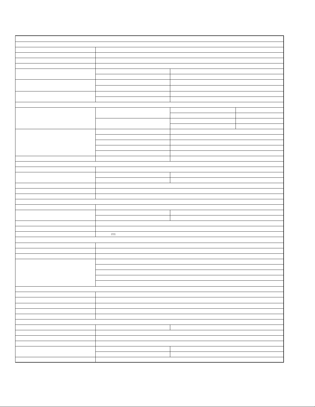
SPECIFICATION
KW-ADV794J/KW-AVX748JW/KW-AVX740J/KW-AVX640J
AMPLIFIER
Power Output 20 W RMS × 4 Channels at 4 Ω and
Signal-to-Noise Ratio 80 dBA (reference: 1 W into 4 Ω)
Load Impedance 4 Ω (4 Ω to 8 Ω allowance)
Equalizer Control Range Level ±12 dB
Audio Output Level
FRONT OUT, REAR OUT, SUBWOOFER OUT
Video Output (composite)
VIDEO OUT
Other Terminals Input
FM/AM TUNER
Frequency Range FM with channel interval set to 200 kHz 87.9 MHz to 107.9 MHz
FM Tuner Usable Sensitivity 9.3 dBf (0.8 µV/75 Ω)
AM Tuner Sensitivity/Selectivity 20 µV/40 dB
DVD/CD
Signal Detection System Non-contact optical pickup (semiconductor laser)
Frequency Response DVD, fs=48 kHz/96 kHz 16 Hz to 22 000 Hz
Dynamic Range 93 dB
Signal-to-Noise Ratio 95 dB
Wow and Flutter Less than measurable limit
USB
USB Standards USB 2.0 Full Speed
Data Transfer Rate
Compatible Device Mass storage class
Compatible File System FAT 32/16/12
Max. Current DC 5 V 1A
BLUETOOTH (Only for KW-ADV794/KW-AVX748/KW-AVX740)
Version Bluetooth 2.0 certified
Output Power +4 dBm Max. (Power class 2)
Service Area Within 10 m (10.9 yd)
Profile
MONITOR
Screen Size 6.1 inch wide liquid crystal display
Number of Pixel
Drive Method TFT (Thin Film Transistor) active matrix format
Color System NTSC/PAL
Aspect Ratio 16:9 (wide)
GENERAL
Power Requirement Operating Voltage DC 14.4 V (11 V to 16 V allowance)
Grounding System Negative ground
Allowable Storage Temperature -10°C to +60°C (14°F to 140°F)
Allowable Operating Temperature 0°C to +40°C (32°F to 104°F)
Dimensions (W × H × D) Installation Size (approx.) 182 mm × 111 mm × 160 mm (7-3/16” × 4-3/8” × 6-5/16”)
Mass (approx.) 2.3 kg (5.1 lbs) (including the Trim plate and Sleeve)
*1 Only for KW-ADV794/KW-AVX748/KW-AVX740
*2 Only for KW-ADV794/KW-AVX740/KW-AVX640.
Design and specifications are subject to change without notice.
If a kit is necessary for your car, consult your telephone directory for the nearest car audio speciality shop.
Line-Out Level/Impedance 4 V/20 kΩ load (full scale)
Output Impedance 1 kΩ
Color System
Video-Out Level/Impedance 1 Vp-p/75Ω
Others Expansion port*2, OE REMOTE, RGB input
AM with channel interval set to 10 kHz 530 kHz to 1 700 kHz
50 dB Quieting Sensitivity 16.3 dBf (1.8 µV/75 Ω)
Alternate Channel Selectivity (400 kHz) 65 dB
Frequency Response 40 Hz to 15 000 Hz
Stereo Separation 40 dB
VCD/CD 16 Hz to 20 000 Hz
Full Speed Maximum 12 Mbps
Low Speed Maximum 1.5 Mbps
HFP (Hands-Free Profile) 1.5
OPP (Object Push Profile) 1.1
A2DP (Advanced Audio Distribution Profile) 1.2
AVRCP (Audio/Video Remote Control Profile) 1.3
PBAP (Phone Book Access Profile) 1.0
1 152 000 pixels : 800 (horizontal) × 3 (RGB) × 480 (vertical)
Panel Size (approx.) 188 mm × 117 mm × 10 mm (7-7/16” × 4-5/8” × 7/16”)
≤ 1% THD+N
PAL/NTSC
LINE IN, VIDEO IN, CAMERA IN, USB input, MIC IN*1, AUX, Antenna input
with channel interval set to 50 kHz 87.5 MHz to 108.0 MHz
with channel interval set to 9 kHz 531 kHz to 1 611 kHz
1-2 (No.MA493<Rev.002>)
Page 3
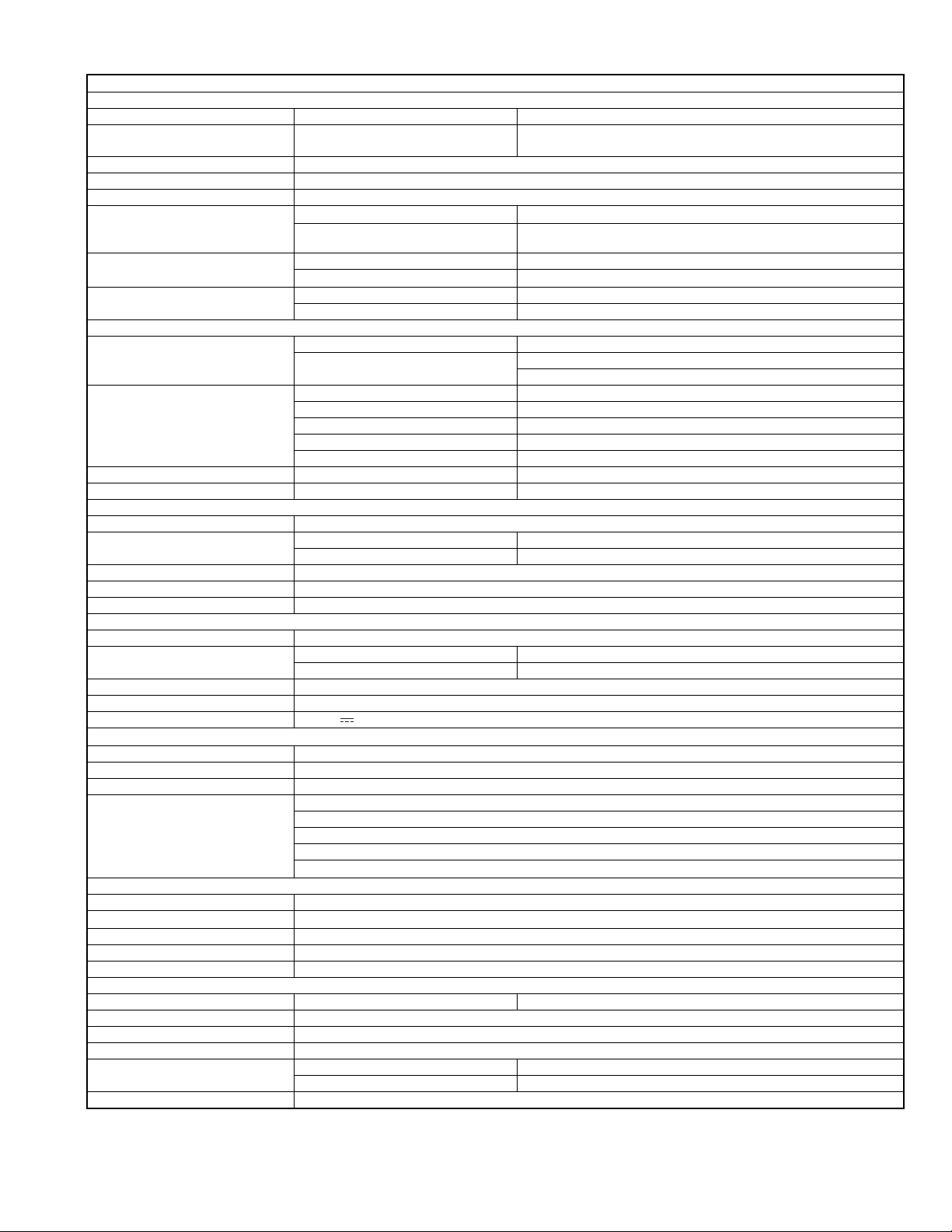
KW-AVX740E/KW-AVX640E/KW-AVX746EU/KW-AVX646EU
AMPLIFIER
Maximum Power Output Front/Rear 50 W per channel
Continuous Power Output (RMS) Front/Rear 20 W per channel into 4 Ω, 40 Hz to 20 000 Hz at no more than 0.8%
total harmonic distortion
Load Impedance 4 Ω (4 Ω to 8 Ω allowance)
Equalizer Control Range Level ±12 dB
Signal-to-Noise Ratio 70 dB
Audio Output Level
FRONT OUT, REAR OUT,
SUBWOOFER OUT
Video Output (composite)
VIDEO OUT
Other Terminals Input
FM/AM TUNER
Frequency Range FM 87.5 MHz to 108.0 MHz
FM Tuner Usable Sensitivity 9.3 dBf (0.8 µV/75 Ω)
MW Tuner Sensitivity/Selectivity 20 µV/40 dB
LW Tuner Sensitivity 50 µV
DVD/CD
Signal Detection System Non-contact optical pickup (semiconductor laser)
Frequency Response DVD, fs=48 kHz/96 kHz 16 Hz to 22 000 Hz
Dynamic Range 93 dB
Signal-to-Noise Ratio 95 dB
Wow and Flutter Less than measurable limit
USB
USB Standards USB 2.0 Full Speed
Data Transfer Rate Full Speed Maximum 12 Mbps
Compatible Device Mass storage class
Compatible File System FAT 32/16/12
Max. Current DC 5 V 1A
BLUETOOTH (Only for KW-AVX740A/KW-AVX746)
Version Bluetooth 2.0 certified
Output Power +4 dBm Max. (Power class 2)
Service Area Within 10 m
Profile
MONITOR
Screen Size 6.1 inch wide liquid crystal display
Number of Pixel
Drive Method TFT (Thin Film Transistor) active matrix format
Color System PAL/NTSC
Aspect Ratio 16:9 (wide)
GENERAL
Power Requirement Operating Voltage DC 14.4 V (11 V to 16 V allowance)
Grounding System Negative ground
Allowable Storage Temperature -10°C to +60°C
Allowable Operating Temperature 0°C to +40°C
Dimensions (W × H × D) Installation Size (approx.) 182 mm × 111 mm × 160 mm
Mass (approx.) 2.3 kg (including the Trim plate and Sleeve)
Line-Out Level/Impedance
Output Impedance
Color System PAL/NTSC
Video-Out Level/Impedance
Others OE REMOTE, RGB input
AM (MW) 531 kHz to 1 611 kHz
50 dB Quieting Sensitivity 16.3 dBf (1.8 µV/75 Ω)
Alternate Channel Selectivity (400 kHz) 65 dB
Frequency Response 40 Hz to 15 000 Hz
Stereo Separation 40 dB
VCD/CD 16 Hz to 20 000 Hz
Low Speed Maximum 1.5 Mbps
HFP (Hands-Free Profile) 1.5
OPP (Object Push Profile) 1.1
A2DP (Advanced Audio Distribution Profile) 1.2
AVRCP (Audio/Video Remote Control Profile) 1.3
PBAP (Phone Book Access Profile) 1.0
1 152 000 pixels : 800 (horizontal) × 3 (RGB) × 480 (vertical)
Panel Size (approx.) 188 mm × 117 mm × 10 mm
4 V/20 kΩ load (full scale)
1 kΩ
1 Vp-p/75 Ω
LINE IN, VIDEO IN, CAMERA IN, USB input, MIC IN*, AUX, Aerial input
(LW) 153 kHz to 279 kHz
* Only for KW-AVX740,KW-AVX746
Design and specifications are subject to change without notice.
(No.MA493<Rev.002>)1-3
Page 4
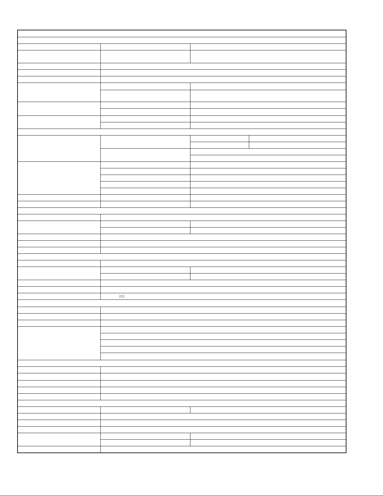
KW-AVX740EE
AMPLIFIER
Maximum Power Output Front/Rear 50 W per channel
Continuous Power Output (RMS) Front/Rear 20 W per channel into 4 Ω, 40 Hz to 20 000 Hz at no more than 0.8%
total harmonic distortion
Load Impedance 4 Ω (4 Ω to 8 Ω allowance)
Equalizer Control Range Level ±12 dB
Signal-to-Noise Ratio 70 dB
Audio Output Level
FRONT OUT, REAR OUT,
SUBWOOFER OUT
Video Output (composite)
VIDEO OUT
Other Terminals Input
FM/AM TUNER
Frequency Range
FM Tuner Usable Sensitivity 9.3 dBf (0.8 µV/75 Ω)
MW Tuner Sensitivity/Selectivity 20 µV/40 dB
LW Tuner Sensitivity 50 µV
DVD/CD
Signal Detection System Non-contact optical pickup (semiconductor laser)
Frequency Response DVD, fs=48 kHz/96 kHz 16 Hz to 22 000 Hz
Dynamic Range 93 dB
Signal-to-Noise Ratio 95 dB
Wow and Flutter Less than measurable limit
USB
USB Standards USB 2.0 Full Speed
Data Transfer Rate Full Speed Maximum 12 Mbps
Compatible Device Mass storage class
Compatible File System FAT 32/16/12
Max. Current DC 5 V 1A
BLUETOOTH
Version Bluetooth 2.0 certified
Output Power +4 dBm Max. (Power class 2)
Service Area Within 10 m
Profile
MONITOR
Screen Size 6.1 inch wide liquid crystal display
Number of Pixel
Drive Method TFT (Thin Film Transistor) active matrix format
Color System PAL/NTSC
Aspect Ratio 16:9 (wide)
GENERAL
Power Requirement Operating Voltage DC 14.4 V (11 V to 16 V allowance)
Grounding System Negative ground
Allowable Storage Temperature -10°C to +60°C
Allowable Operating Temperature 0°C to +40°C
Dimensions (W × H × D) Installation Size (approx.) 182 mm × 111 mm × 160 mm
Mass (approx.) 2.3 kg (including the Trim plate and Sleeve)
Design and specifications are subject to change without notice.
Line-Out Level/Impedance
Output Impedance
Color System PAL/NTSC
Video-Out Level/Impedance
Others OE REMOTE, RGB input
FM
AM (MW) 531 kHz to 1 611 kHz
50 dB Quieting Sensitivity 16.3 dBf (1.8 µV/75 Ω)
Alternate Channel Selectivity (400 kHz) 65 dB
Frequency Response 40 Hz to 15 000 Hz
Stereo Separation 40 dB
VCD/CD 16 Hz to 20 000 Hz
Low Speed Maximum 1.5 Mbps
HFP (Hands-Free Profile) 1.5
OPP (Object Push Profile) 1.1
A2DP (Advanced Audio Distribution Profile) 1.2
AVRCP (Audio/Video Remote Control Profile) 1.3
PBAP (Phone Book Access Profile) 1.0
1 152 000 pixels : 800 (horizontal) × 3 (RGB) × 480 (vertical)
Panel Size (approx.) 188 mm × 117 mm × 10 mm
4 V/20 kΩ load (full scale)
1 kΩ
1 Vp-p/75 Ω
LINE IN, VIDEO IN, CAMERA IN, USB input, MIC IN, AUX, Aerial input
FM1, FM2 87.5 MHz to 108.0 MHz
FM3 65.00 MHz to 74.00 MHz
(LW) 153 kHz to 279 kHz
1-4 (No.MA493<Rev.002>)
Page 5
KW-AVX746A/KW-AVX746U,UT/KW-AVX646U,KW-AVX648UF
AMPLIFIER
Maximum Power Output Front/Rear 50 W per channel
Continuous Power Output (RMS) Front/Rear 20 W per channel into 4 Ω, 40 Hz to 20 000 Hz at no more than 0.8% total
harmonic distortion
Load Impedance 4 Ω (4 Ω to 8 Ω allowance)
Equalizer Control Range Level ±12 dB
Signal-to-Noise Ratio 70 dB
Audio Output Level
FRONT OUT, REAR OUT,
SUBWOOFER OUT
Video Output (composite)
VIDEO OUT
Other Terminals Input
FM/AM TUNER
Frequency Range FM 87.5 MHz to 108.0 MHz
FM Tuner Usable Sensitivity 9.3 dBf (0.8 µV/75 Ω)
AM Tuner Sensitivity/Selectivity 20 µV/40 dB
DVD/CD
Signal Detection System Non-contact optical pickup (semiconductor laser)
Frequency Response DVD, fs=48 kHz/96 kHz 16 Hz to 22 000 Hz
Dynamic Range 93 dB
Signal-to-Noise Ratio 95 dB
Wow and Flutter Less than measurable limit
USB
USB Standards USB 2.0 Full Speed
Data Transfer Rate Full Speed Maximum 12 Mbps
Compatible Device Mass storage class
Compatible File System FAT 32/16/12
Max. Current DC 5 V 1A
BLUETOOTH (Only for KW-AVX746)
Version Bluetooth 2.0 certified
Output Power +4 dBm Max. (Power class 2)
Service Area Within 10 m
Profile
MONITOR
Screen Size 6.1 inch wide liquid crystal display
Number of Pixel
Drive Method TFT (Thin Film Transistor) active matrix format
Color System PAL/NTSC
Aspect Ratio 16:9 (wide)
GENERAL
Power Requirement Operating Voltage DC 14.4 V (11 V to 16 V allowance)
Grounding System Negative ground
Allowable Storage Temperature -10°C to +60°C
Allowable Operating Temperature 0°C to +40°C
Dimensions (W × H × D)
Mass (approx.) 2.0 kg
Line-Out Level/Impedance
Output Impedance
Color System PAL/NTSC
Video-Out Level/Impedance
Others OE REMOTE, RGB input
AM 531 kHz to 1 611 kHz
50 dB Quieting Sensitivity 16.3 dBf (1.8 µV/75 Ω)
Alternate Channel Selectivity (400 kHz) 65 dB
Frequency Response 40 Hz to 15 000 Hz
Stereo Separation 40 dB
VCD/CD 16 Hz to 20 000 Hz
Low Speed Maximum 1.5 Mbps
HFP (Hands-Free Profile) 1.5
OPP (Object Push Profile) 1.1
A2DP (Advanced Audio Distribution Profile) 1.2
AVRCP (Audio/Video Remote Control Profile) 1.3
PBAP (Phone Book Access Profile) 1.0
1 152 000 pixels : 800 (horizontal) × 3 (RGB) × 480 (vertical)
Installation Size (approx.)
Panel Size (approx.) 188 mm × 117 mm × 10 mm
4 V/20 kΩ load (full scale)
1 kΩ
1 Vp-p/75 Ω
LINE IN, VIDEO IN, CAMERA IN, USB input, MIC IN*, AUX, Aerial input
182 mm × 111 mm × 160 mm
180 mm × 100 mm × 160 mm (KW-AVX648)
* Only for KW-AVX746
Design and specifications are subject to change without notice.
(No.MA493<Rev.002>)1-5
Page 6
SECTION 1
PRECAUTION
1.1 Safety Precautions
(1) This design of this product contains special hardware and
many circuits and components specially for safety purposes. For continued protection, no changes should be made
to the original design unless authorized in writing by the
manufacturer. Replacement parts must be identical to
those used in the original circuits. Services should be performed by qualified personnel only.
(2) Alterations of the design or circuitry of the product should
not be made. Any design alterations of the product should
not be made. Any design alterations or additions will void
the manufacturers warranty and will further relieve the
manufacture of responsibility for personal injury or property
damage resulting therefrom.
(3) Many electrical and mechanical parts in the products have
special safety-related characteristics. These characteristics are often not evident from visual inspection nor can the
protection afforded by them necessarily be obtained by using replacement components rated for higher voltage, wattage, etc. Replacement parts which have these special
safety characteristics are identified in the Parts List of Service Manual. Electrical components having such features
are identified by shading on the schematics and by ( ) on
the Parts List in the Service Manual. The use of a substitute
replacement which does not have the same safety characteristics as the recommended replacement parts shown in
the Parts List of Service Manual may create shock, fire, or
other hazards.
(4) The leads in the products are routed and dressed with ties,
clamps, tubings, barriers and the like to be separated from
live parts, high temperature parts, moving parts and/or
sharp edges for the prevention of electric shock and fire
hazard. When service is required, the original lead routing
and dress should be observed, and it should be confirmed
that they have been returned to normal, after reassembling.
(5) Leakage shock hazard testing
After reassembling the product, always perform an isolation check on the exposed metal parts of the product (antenna terminals, knobs, metal cabinet, screw heads,
headphone jack, control shafts, etc.) to be sure the product
is safe to operate without danger of electrical shock.Do not
use a line isolation transformer during this check.
• Plug the AC line cord directly into the AC outlet. Using a
"Leakage Current Tester", measure the leakage current
from each exposed metal parts of the cabinet, particularly any exposed metal part having a return path to the
chassis, to a known good earth ground. Any leakage current must not exceed 0.5mA AC (r.m.s.).
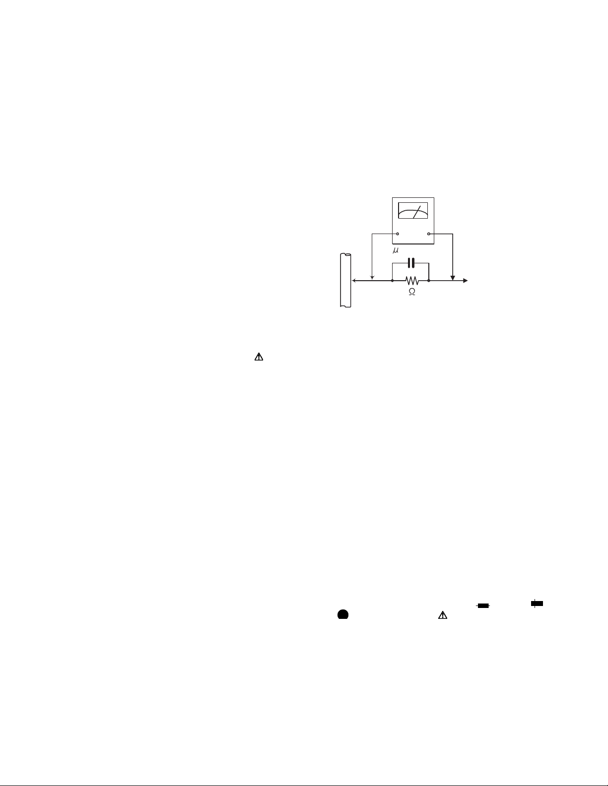
• Alternate check method
Plug the AC line cord directly into the AC outlet. Use an
AC voltmeter having, 1,000Ω per volt or more sensitivity
in the following manner. Connect a 1,500Ω 10W resistor
paralleled by a 0.15µF AC-type capacitor between an exposed metal part and a known good earth ground.
Measure the AC voltage across the resistor with the AC
voltmeter.
Move the resistor connection to each exposed metal
part, particularly any exposed metal part having a return
path to the chassis, and measure the AC voltage across
the resistor. Now, reverse the plug in the AC outlet and
repeat each measurement. Voltage measured any must
not exceed 0.75 V AC (r.m.s.). This corresponds to 0.5
mA AC (r.m.s.).
AC VOLTMETER
(Having 1000
ohms/volts,
or more sensitivity)
0.15 F AC TYPE
Place this
probe on
1500 10W
Good earth ground
1.2 Warning
(1) This equipment has been designed and manufactured to
meet international safety standards.
(2) It is the legal responsibility of the repairer to ensure that
these safety standards are maintained.
(3) Repairs must be made in accordance with the relevant
safety standards.
(4) It is essential that safety critical components are replaced
by approved parts.
(5) If mains voltage selector is provided, check setting for local
voltage.
1.3 Caution
Burrs formed during molding may be left over on some parts
of the chassis.
Therefore, pay attention to such burrs in the case of preforming repair of this system.
1.4 Critical parts for safety
In regard with component parts appearing on the silk-screen
printed side (parts side) of the PWB diagrams, the parts that are
printed over with black such as the resistor ( ), diode ( )
and ICP ( ) or identified by the " " mark nearby are critical
for safety. When replacing them, be sure to use the parts of the
same type and rating as specified by the manufacturer.
(This regulation dose not Except the J and C version)
each exposed
metal part.
1-6 (No.MA493<Rev.002>)
Page 7
1.5 Preventing static electricity
Electrostatic discharge (ESD), which occurs when static electricity stored in the body, fabric, etc. is discharged, can destroy the laser
diode in the traverse unit (optical pickup). Take care to prevent this when performing repairs.
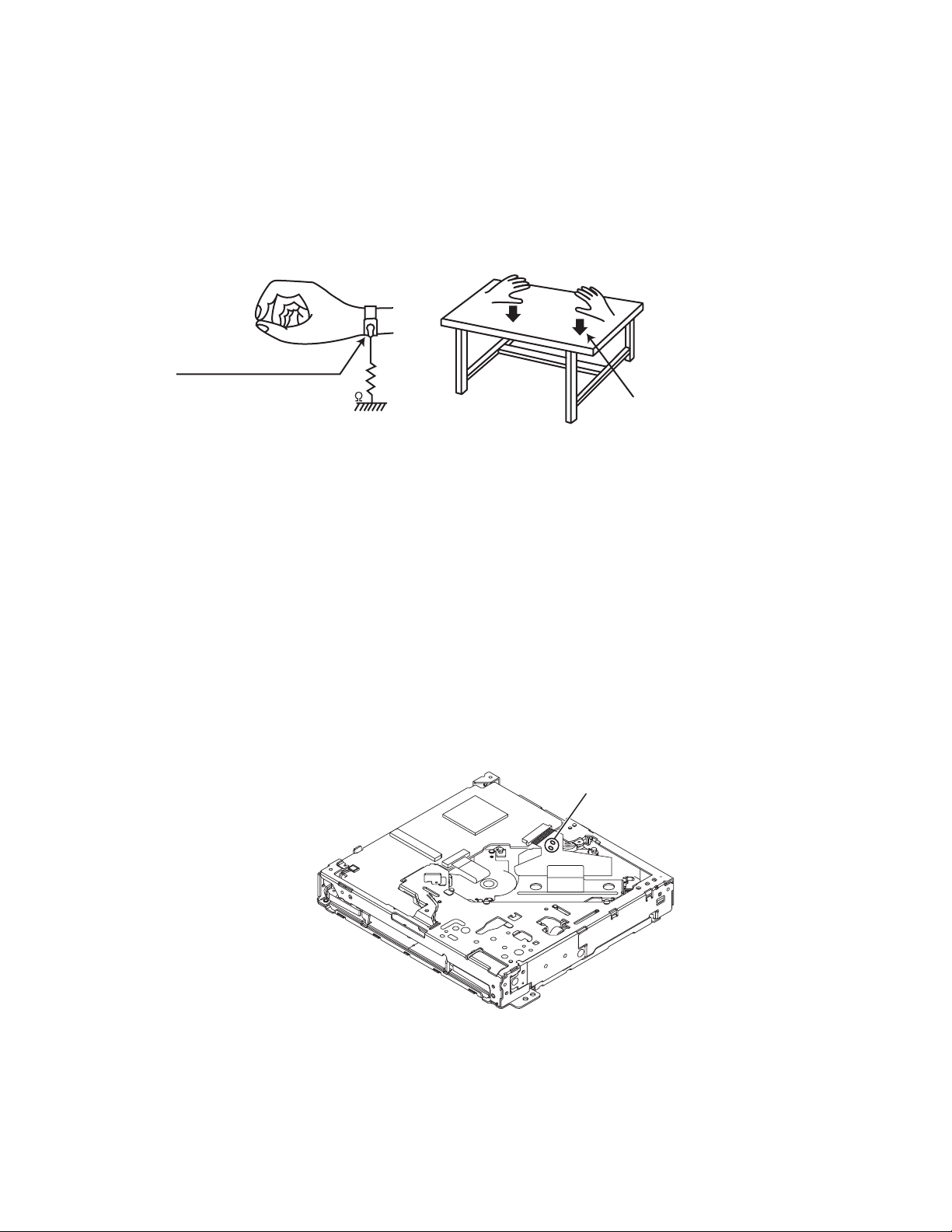
1.5.1 Grounding to prevent damage by static electricity
Static electricity in the work area can destroy the optical pickup (laser diode) in devices such as laser products.
Be careful to use proper grounding in the area where repairs are being performed.
(1) Ground the workbench
Ground the workbench by laying conductive material (such as a conductive sheet) or an iron plate over it before placing the
traverse unit (optical pickup) on it.
(2) Ground yourself
Use an anti-static wrist strap to release any static electricity built up in your body.
(caption)
Anti-static wrist strap
1M
Conductive material
(conductive sheet) or iron plate
(3) Handling the optical pickup
• In order to maintain quality during transport and before installation, both sides of the laser diode on the replacement optical
pickup are shorted. After replacement, return the shorted parts to their original condition.
(Refer to the text.)
• Do not use a tester to check the condition of the laser diode in the optical pickup. The tester's internal power source can easily
destroy the laser diode.
1.6 Handling the traverse unit (optical pickup)
(1) Do not subject the traverse unit (optical pickup) to strong shocks, as it is a sensitive, complex unit.
(2) Cut off the shorted part of the flexible cable using nippers, etc. after replacing the optical pickup. For specific details, refer to the
replacement procedure in the text. Remove the anti-static pin when replacing the traverse unit. Be careful not to take too long a
time when attaching it to the connector.
(3) Handle the flexible cable carefully as it may break when subjected to strong force.
(4) It is not possible to adjust the semi-fixed resistor that adjusts the laser power. Do not turn it.
1.7 Attention when traverse unit is decomposed
*Please refer to "Disassembly method" in the text for the pickup unit.
• Apply solder to the short land before the card wire is disconnected from the connector on the pickup unit.
(If the card wire is disconnected without applying solder, the pickup may be destroyed by static electricity.)
• In the assembly, be sure to remove solder from the short land after connecting the card wire.
Solder short part
(No.MA493<Rev.002>)1-7
Page 8

1.8 Important for laser products
1.CLASS 1 LASER PRODUCT
2.CAUTION :
(For U.S.A.) Visible and/or invisible class II laser radiation
when open. Do not stare into beam.
(Others) Visible and/or invisible class 1M laser radiation
when open. Do not view directly with optical instruments.
3.CAUTION : Visible and/or invisible laser radiation when
open and inter lock failed or defeated. Avoid direct
exposure to beam.
4.CAUTION : This laser product uses visible and/or invisible
laser radiation and is equipped with safety switches which
prevent emission of radiation when the drawer is open and
the safety interlocks have failed or are defeated. It is
dangerous to defeat the safety switches.
5.CAUTION : If safety switches malfunction, the laser is able
to function.
6.CAUTION : Use of controls, adjustments or performance of
procedures other than those specified here in may result in
hazardous radiation exposure.
!
Please use enough caution not to
see the beam directly or touch it
in case of an adjustment or operation
check.
REPRODUCTION AND POSITION OF LABELS and PRINT
WARNING LABEL and PRINT
1-8 (No.MA493<Rev.002>)
Page 9

SECTION 2
SPECIFIC SERVICE INSTRUCTIONS
This service manual does not describe SPECIFIC SERVICE INSTRUCTIONS.
SECTION 3
DISASSEMBLY
3.1 Main body (Used model: KD-AVX740)
3.1.1 Removing the Front chassis (See Fig.1 and 2)
(1) Remove the three screws A. (See Fig.1)
(2) Disengage two hooks a engaged the Front chassis. (See
Fig.1)
a
A
Fig.1
(3) Remove the four screws B attaching the both side of the
Front chassis. (See Fig.2)
(4) Disengage two hooks b engaged both side of the Front
chassis. (See Fig.2)
3.1.2 Removing the Heat sink (See Fig.3)
(1) Remove the three screws C and two screws D attaching
the Heat sink.
C
D
Fig.3
3.1.3 Removing the Rear heat sink (See Fig 4)
(1) Remove the two screws E and two screws F attaching the
Rear heat sink
EF
Fig.2
b
B
Fig.4
3.1.4 Removing the DVD mechanism (See Fig.5, 6, 7, 8, 9)
(1) Disconnect the card wire from DVD mechanism connected
to connector CN105
of the Main board. (See Fig.5)
CN105
Fig.5
(No.MA493<Rev.002>)1-9
Page 10

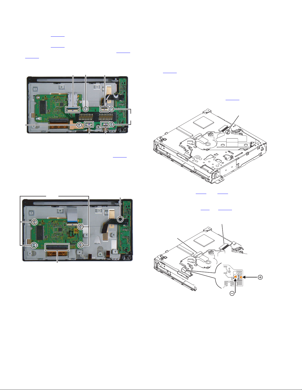
(2) Remove the two screws G attaching the Top chassis. (See
Fig.6)
G
(5) Remove the three screws K attaching the DVD mecha-
nism. (See Fig.9)
K
K
Fig.6
(3) Remove the one screw H attaching the Top chassis. (See
Fig.7)
H
Fig.7
(4) Remove the four screws J attaching the Top chassis. (See
Fig.8)
J
Fig.9
3.1.5 Removing the BT amp board (See Fig.10)
(1) Disconnect the card wire from Main board connected to
connector CN311
(2) Disconnect connector wire from Sub amp board connected
to connector CN341
(3) Remove the four screws L attaching the BT amp board.
CN311
3.1.6 Removing the Sub amp board (See Fig.11, 12)
(1) Remove the one screw M attaching the Sub amp board.
(See Fig.11)
of the BT amp board.
of the BT amp board.
CN341
Fig.10
L
1-10 (No.MA493<Rev.002>)
Fig.8
M
Fig.11
Page 11

(2) Disconnect the card wire from Main board connected to
connectors CN201
Fig.12)
(3) Disconnect the Car cable connected to connector CN104
of the Main board. (See Fig.12)
(4) Disconnect the Car cable connected to connector CN241
of the Sub amp board. (See Fig.12)
(5) Remove the three screws N attaching the Sub amp board.
(Se Fig.12)
CN104
CN201
CN202
and CN202 of the Sub amp board. (See
3.1.8 Removing the Center chassis (See Fig.15)
(1) Remove the four screws R attaching the Center chassis.
R
R
N
CN241
Fig.12
3.1.7 Removing the Rear panel (See Fig.13, 14)
(1) Disconnect the connector wire from Car cable connected to
connector CN101 of the Main board. (See Fig.13)
(2) Disconnect the connector wire from FAN connected to con-
nector CN112 of the Main board. (See Fig.13)
N
Fig.15
3.1.9 Removing the Main board (See Fig.16)
(1) Remove the four screws S attaching the Main board.
S
Fig.16
3.1.10 Removing the Rear cover (See Fig.17)
(1) Remove the four screws T and four screws U attaching the
Rear cover.
(2) Disengage the four hooks c engaging the Rear cover.
S
CN101
(3) Remove the six screws P and two screws Q attaching the
Rear panel. (Se Fig.14)
CN112
Fig.13
P
P
Q
Fig.14
c
c
T
T
U
Fig.17
(No.MA493<Rev.002>)1-11
Page 12
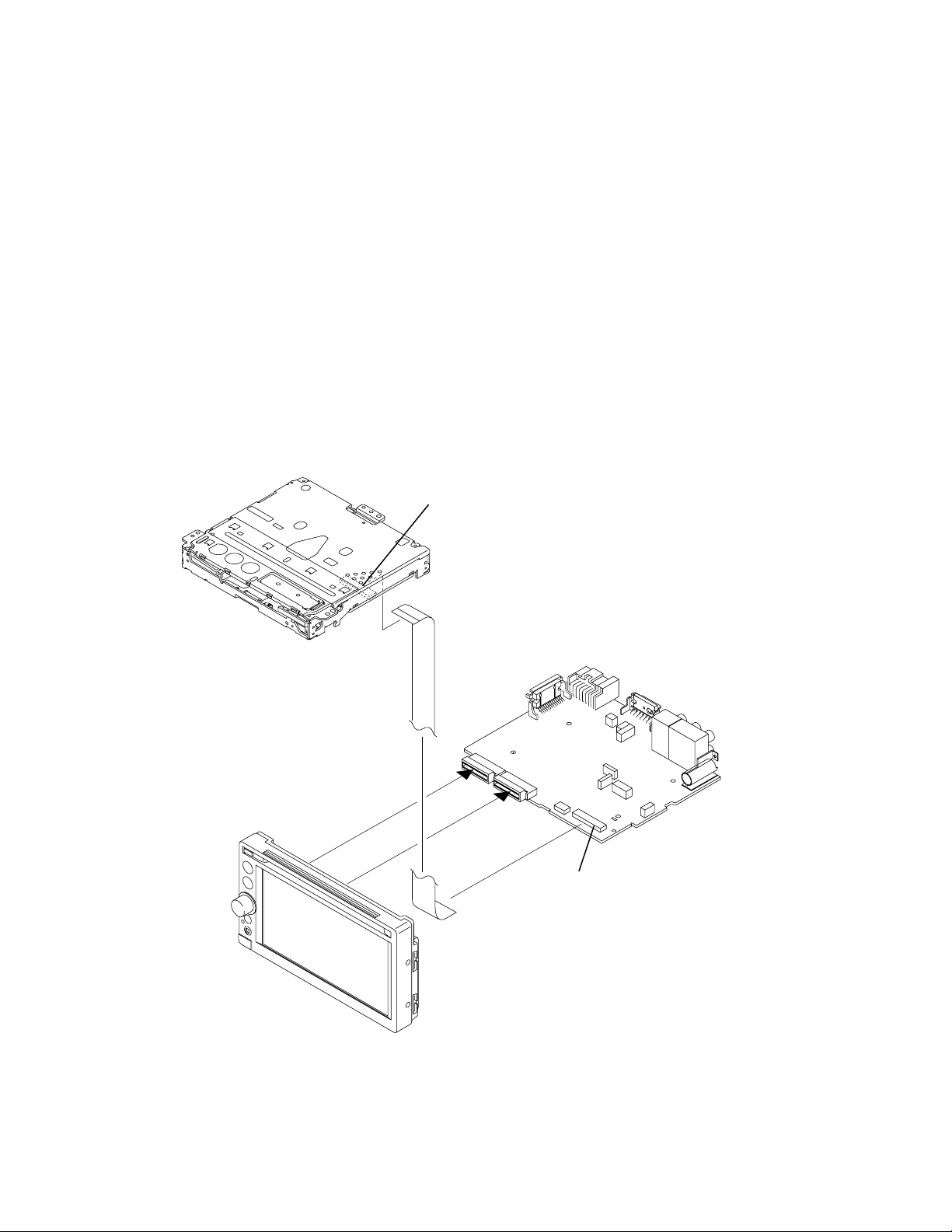
3.1.11 Removing the Panel-B board (See Fig.18)
V
(1) Disconnect the card wires from Panel-A board connected
to connector CN603
of the Panel-B board.
(2) Disconnect the card wires from Panel-B board connected
to connector CN604
of the Panel-B board.
(3) Disconnect the FPC connected to connectors CN604
of the Panel-B board.
CN605
(4) Remove the four screws V attaching the Panel-B board.
V
CN604CN603
V
and
3.2 DVD mechanism assembly section
3.2.1 Removing the Traverse mechanism assembly (See
Fig.1 to 6)
(1) Solder the short land section on the flexible wire of pickup.
(See Fig.1)
Caution:
* Solder the short land section on the flexible wire of pickup
before disconnecting the flexible wire form the connector
on the Front end board.
CN101
If the flexible wire is disconnected without attaching the
solder, the pickup may be destroyed by static electricity.
* When attaching the Traverse mechanism assembly, remove the solder from the short land section after connection
the flexible wire to the connector CN101
on the Front end
board.
Solder short part
CN606
CN605
Fig.18
3.1.12 Removing the Panel-A board (See Fig.19)
(1) Disconnect the FPC connected to connector CN501
Panel-A board.
(2) Remove the four screws W attaching the Panel-A board.
3.1.13 Removing the SW board (See Fig.19)
(1) Remove the volume knob
(2) Remove the one screw X attaching the SW board.
W
X
CN501
Fig.19
of the
Fig.1
(2) Voltage supply to TP79
and TP81 approx DC 3.0V until
Clamper is shift to loading complete position. (See Fig.2)
(3) Disconnect the flexible wires from Traverse mechanism assembly
connected to connector CN1
and CN101 of the Front end board.
(See Fig.2)
CN101
CN1
TP79 TP81
TP79
R317
TP67
R312
R21
R357
TP81
TP92
CENTER
D-
DGND_7
WOOFER
Voltage supply
position
Fig.2
1-12 (No.MA493<Rev.002>)
Page 13

(4)
Remove the five screws A attaching the Top cover assembly. (See Fig.
3)
A
Fig.3
(5) From the bottom side, disconnect the connector wire from
Top cover assembly connected to connector CN2
Front end board. (See Fig.4)
CN2
of the
3.2.2 Removing the Front end board (See Fig.7)
(1) Remove the Motor wires from loading motor soldered to
and TP81 of the Front end board.
TP79
(2) Remove the two screws B attaching the Front end board.
TP81
TP79
B
B
Fig.7
3.2.3 Removing the Loading arm assembly (See Fig.8)
(1) Remove the Loading arm spring L from Loading arm assembly.
(2) Slide to left side and then disengage hook a then hook b.
hook b
Loading arm
assembly
hook
a
Fig.4
(6) From the bottom side, remove the spring from Traverse
mechanism assembly. (See Fig.5)
Fig.5
(7) From the top side, pull up the traverse mechanism and disengage
three dumper positions. (See Fig.6)
Loading arm spring L
Fig.8
3.2.4 Removing the Gear base assembly (See Fig.9, 10)
(1) Remove the Loading arm spring L. (See Fig.9)
Loading arm
spring L
(Different color sprin
Fig.6
Dumper
Fig.9
(No.MA493<Rev.002>)1-13
Page 14

(2) Remove the two screws C attaching the Gear base assembly.
r
(See Fig.10)
C
Fig.10
3.2.5 Removing the Loading arm holder. (See Fig.11)
(1) Remove the two screws D attaching the Loading arm holder.
(2) Remove the Loading arm spring R.
D
Loading arm
holder
3.2.7 Removing the Slide cam assembly (See Fig.13)
(1) Slide to backward the Slide cam assembly and the remove
the Slide cam spring.
(2) Slide to frontward the slide cam assembly, and then take
out it.
Slide cam assembly
Slide cam spring
Fig.13
3.2.8 Removing the Photo board (See Fig.14)
(1) Pressing the hook c and then slide to backward (slide to the
arrow side) the Disc plate.
(2) Remove the one screw F attaching the Photo board.
hook
c
hook
c
Loading arm
spring R
Fig.11
3.2.6 Removing the Loading moor assembly (See Fig.12)
(1) Remove the three screws E attaching the Loading motor
assembly.
E
Photo board
F
Fig.14
3.2.9 Removing the Loading motor (See Fig.15 to 18)
(1) Remove the A wheel gear. (See Fig.15)
A Wheel gea
Fig.15
1-14 (No.MA493<Rev.002>)
Fig.12
Page 15

(2) Remove the A worm gear, M connect gear and M wheel
t
gear by sequentially. (See Fig.16)
A worm gear
M connect gear
M wheel gear
3.2.10 Removing the Roller assembly (See Fig.19)
(1) Remove the Slit washer.
(2) Remove the R middle gear.
(3) Remove the R connect gear.
(4) Snap off the part a of the Roller assembly.
Lift up the part b of the Roller assembly, and then release part
(5)
(When release part c, R collar R is easy to come off, does not lose it).
CAUTION:
When reattach the Roller assembly, Middle gear should keep
direction and Slit washer should be change new part.
R middle gear
Direction
R collar
c
Fig.16
(3) Remove the two screws G attaching the Loading motor.
(Se Fig.17)
G
Fig.17
(4) When attaching the Loading motor, motor wire should arrange
to figure. (See Fig.18)
Wire arrangement
Fig.18
R connect gear
Slit washer
part c
part a
part b
Fig.19
3.2.11 Removing the Roller (See Fig.20)
(1) Remove the Slit washer.
(2) Pull out the Roller shaft.
CAUTION:
When reattach the Roller shaft, Slit washer should be change new part.
slit
keep direction
keep direction
sli
small side
Fig.20
(No.MA493<Rev.002>)1-15
Page 16
SECTION 4
ADJUSTMENT
4.1 Service mode
4.2 Test instruments required for adjustment
(1) Digital oscilloscope (100MHz)
(2) Digital tester
(3) Test Disc
(4) Extension cable :EXTXD001-50PF (CN403 --- CN105)
4.5 Dummy load
Exclusive dummy load should be used for AM and FM.
For FM dummy load, there is a loss of 6dB between SSG output and antenna input.
The loss of 6dB need not be considered since direct reading of figures are applied in this working standard.
4.6 How to connect the extension cable for adjusting
Caution:
Be sure to attach the heat sink and rear bracket onto the power amplifier IC and regulator IC respectively, before supply the power.
If voltage is applied without attaching these parts, the power amplifier IC and regulator IC will be destroyed by heat.
4.3 Standard measuring conditions
Power supply voltage DC14.4V(10.5 to 16V)
Load impedance 20K ohm (2 Speakers connection)
Output Level Line out 2.5V (Vol. MAX)
4.4 Standard volume position
Balance and Bass &Treble volume : lndication"0"
Loudness : OFF
CN403
EXTXD001-50PF
CN105
1-16 (No.MA493<Rev.002>)
Page 17

4.7 Service mode
4.7.1 Set to Service Mode.
MENU
Area A Area B
TOUCH PANEL
(Multiplex push timing chart.)
[MENU] Key ON (HOLD)
[Area A] Key ON
[Area B] Key ON
Shift to Service Mode
4.7.2 Service mode menu
SYS Vxxxx TUN:x TEMPERATURE SYS V: System micon version.
APP Axxxx MON:x DVD CHECK MODE APP A: Apprication software version
DATA Vxxxx TOU:x RUNNING MODE DATA V: Imae data version
DISC Vxxxx ERROR DIAG/DATA DISC V: DVD module version
Macrovision xxxx Macrovision: Macrovision version
DivX xxxx DivX: DivX version
BT Vxxx RDS TEST MODE BT V: Bluetooth firmware version
Span x BT MIC TEST Span x: No use
SYS-Area: x BT DONGLE CHECK SYS-Area: System area and Model name
DISC-Area: xx reg: x FIRM UPDATE MODE DISC-Area: Disc area reg: Region
S,No xxxxxxxx TUN: S meter level offset adjust Y=Adjust OK N=Not adjust
INITIALIZE ALL
BACK EXIT
MON: Monitor Adjust Y= Adjust OK N=Not adjust
TOU: Touch panel adjust Y= Adjust OK N=Not adjust
INITIALIZE ALL
Initialized content.
Backup memory. Installer memory. User memory. Tuner area setting.
Error history. Diag data. EEPROM in the DVD module.
EEPROM in the bluetooth module.
TEMPERATURE
Temperature display of DVD module.
DVD CHECK MODE
.
See "DVD CHECK MODE” for details.
RUNNING MODE (No use)
ERROR DIAG/DATA (Error history display)
DVD ERROR: Error history of DVD module.
DVD ERROR TOTAL xxxx
E1:xxxxxx E2:xxxxxx E3:xxxxxx
xxxxxx xxxxxx xxxxxx xxxxxx xxxxxx
DVD ERROR CLR
MECHA ERROR CLR
MECHA ERROR: Error history of
door mechanism.
(Except KW-AVX64x series)
Power detected: Frequency in which
MECHA ERROR TOTAL xxxx
E1:xxxxxx E2:xxxxxx E3:xxxxxx
xxxxxx xxxxxx xxxxxx xxxxxx xxxxxx
DC ERROR CLR
power supply is turned on.
DISC EJECT: Eject frequency.
Power supply CLR key (No display)
DC1 OK DC2 0
Power detected (xxxxxx)
DISC EJECT xxxtimes
BACK EXIT
RDS TEST MODE (No use)
BT MIC TEST (Except KW-AVX64x series)
BT MICROPHONE TEST
IN PROGRESS
BACK EXIT
The voice from microphone is output to the speaker.
If the "BACK" button or "EXIT" button is pudhed, the test is ended.
The come off the mode, power supply off is done.
BT DONGLE CHECK (No use)
FIRM UPDATE MODE
When the firmware updated, it uses it.
(No.MA493<Rev.002>)1-17
Page 18

DVD CHECK MODE
xxxxxxxx DVDx1 JITTER MODE
xxxx xxxx SEARCH & JITTER
MONITOR
DVDx1 PLAY
NORMAL PLAY STOP
EF OUT-TRACKING OFF EJECT
EF IN-TRACKING OFF LOAD
CD-LASER ON SLEEP
DVD-LASER ON EEPROM DATA OSD
Command Mechanism unit operation Indication contents
NORMAL PLAY Start at normal speed
Laser current value, jitter value
(After start, jitter is measured by an inner position.)
EF OUT-TRACKING OFF Tracking off the outermost position of CD For EF phase error
EF IN-TRACKING OFF Tracking off the innermost position of CD For EF phase error
CD-LASER ON CD_LD lights and laser current is displayed. Laser current value, jitter value
DVD-LASER ON DVD_LD lights and laser currrent is displayed Laser current value, jitter value
DVDx1 JITTER MODE DVD x1 jitter measuring mode
Laser current value, jitter value
(for use in mechanism adjustment)
SEARCH & JITTER The search and jitter measurement to an appointed
position of DVD.
Position measured with VT-501
jitter value
MONITOR Monitor terminal setting
DVDx1 PLAY DVD x1 stopped start
Not displayed.
(After start, jitter is measured by an inner position.)
STOP Disc stopped, LD-OFF Not displayed.
EJECT EJECT Not displayed.
LOAD LOADING Not displayed.
SLEEP SLEEP Not displayed.
EEPROM DATA OSD EEPROM DATA (Only Engineer use)
1-18 (No.MA493<Rev.002>)
Page 19

5.1
16PIN CORD DIAGRAM
5.1.1 Except Europe
SECTION 5
TROUBLESHOOTING
1
16
2
9
10
12
11
8
7
6
5
3
2
1
BK
YL
RD
GN
GN / BK
VI
VI / BK
WH
WH/BK
GY/BK
BL
BL/WH
RD
BK
GN
GN/BK
VI/BK
VIGY
LB/YL
BR
OR/WH
YL
10
11
12
134
14
15
16
9
GN
VI
LB
YL
BR
OR
Green
Violet
Light Blue
Yellow
Brown
Orange
White
WH
BK
Black
GY
Gray
BL Blue
Red
RD
15
13
4
3
14
8
7
5
6
OR / WH
LB / YL
BL
BL / WH
BR
WH
WH / BK
GY
GY / BK
(No.MA493<Rev.002>)1-19
Page 20

5.1.2 For Europe
8
7
6
5
4
3
WH
WH/BK
GY/BK
GY
NC
BL/WH
GN
GN/BK
VI/BK
VI
LB/YL
BR
10
11
12
13
14
White
WH
Black
BK
GY
BL
RD
Gray
Blue
Red
9
GN
VI
LB
YL
BR
OR
Green
Violet
Light Blue
Yellow
Brown
Orange
2
16
1
14
15
3
9
10
12
11
8
7
5
6
13
2
1
RD 1
YL 1
BK
BR
OR / WH
BL / WH
GN
GN / BK
VI
VI / BK
WH
WH / BK
GY
GY / BK
LB / YL
RD1
BK
OR/WH
YL1
15
16
1
VI
3
GY
5
WH
7
GN
2
4
6
8
VI/BK
GY/BK
WH/BK
GN/BK
RD 3
9
NC
10
11
13
BL/WH
RD2
15 16
NC
12
14
BR
YL2
OR/WH
BK
RD 2
15
YL 2
12
16
10
14
13
7
8
1
2
5
6
3
4
1-20 (No.MA493<Rev.002>)
Page 21

(No.MA493<Rev.002>)1-21
Page 22

Victor Company of Japan, Limited
Mobile Entertainment Division 2967-3, Ishikawa-machi, Hachioji-shi, Tokyo, 192-8525, Japan
(No.MA493<Rev.002>)
Printed in Japan
VSE
 Loading...