

Page 1
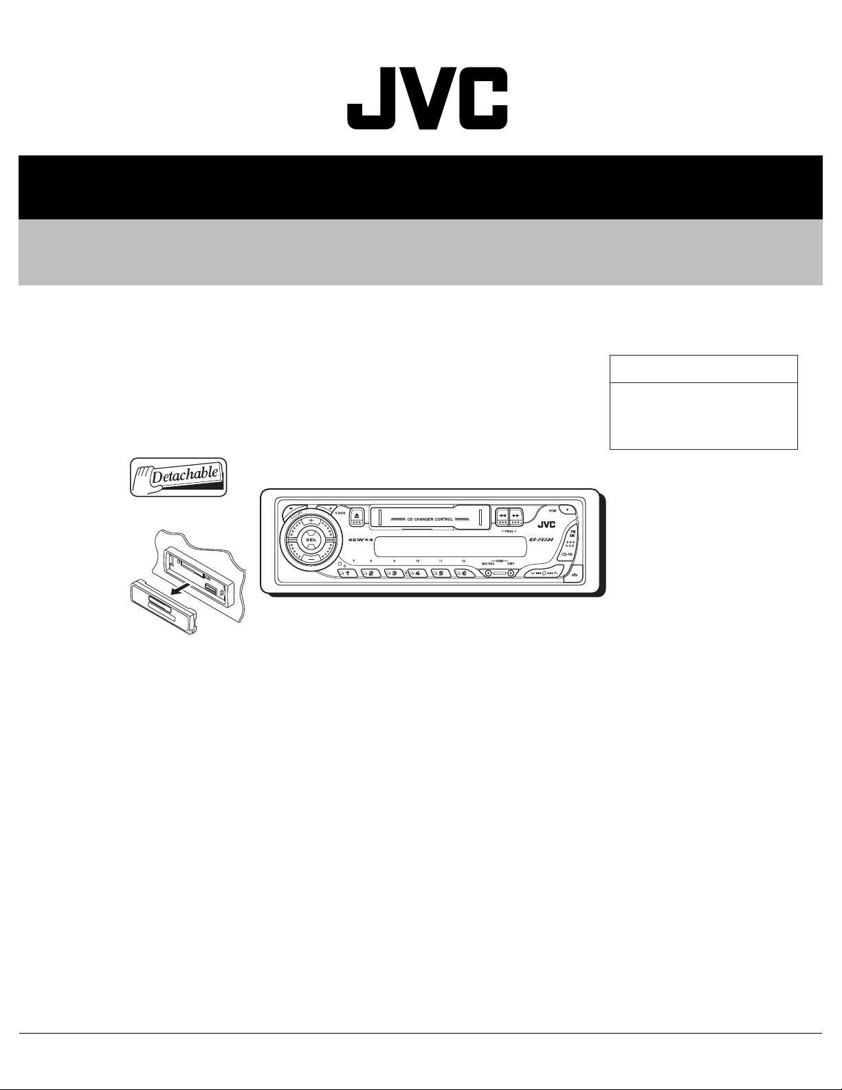
SERVICE MANUAL
CASSETTE RECEIVER
MA18220054
KS-FX384
KS-FX384
Area suffix
UI ---------------------------- India
TABLE OF CONTENTS
1 PRECAUTION. . . . . . . . . . . . . . . . . . . . . . . . . . . . . . . . . . . . . . . . . . . . . . . . . . . . . . . . . . . . . . . . . . . . . . . . . 1-3
2 SPECIFIC SERVICE INSTRUCTIONS . . . . . . . . . . . . . . . . . . . . . . . . . . . . . . . . . . . . . . . . . . . . . . . . . . . . . . 1-4
3 DISASSEMBLY . . . . . . . . . . . . . . . . . . . . . . . . . . . . . . . . . . . . . . . . . . . . . . . . . . . . . . . . . . . . . . . . . . . . . . . 1-5
4 ADJUSTMENT . . . . . . . . . . . . . . . . . . . . . . . . . . . . . . . . . . . . . . . . . . . . . . . . . . . . . . . . . . . . . . . . . . . . . . . 1-13
5 TROUBLESHOOTING . . . . . . . . . . . . . . . . . . . . . . . . . . . . . . . . . . . . . . . . . . . . . . . . . . . . . . . . . . . . . . . . . 1-17
COPYRIGHT © 2005 Victor Company of Japan, Limited
No.MA182
2005/4
Page 2
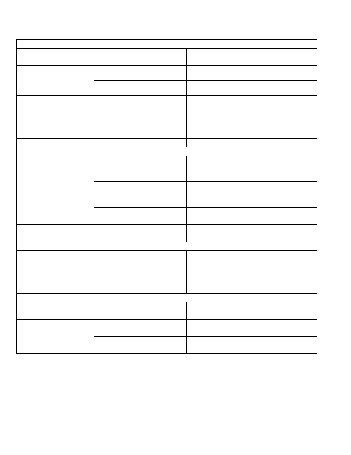
SPECIFICATION
AUDIO AMPLIFIER SECTION
Maximum Power Output Front 45 W per channel
Rear 45 W per channel
Continuous Power Output (RMS) Front 17 W per channel into 4 Ω, 40 Hz to 20 000 Hz at no more
than 0.8% total harmonic distortion.
Rear 17 W per channel into 4 Ω, 40 Hz to 20 000 Hz at no more
than 0.8% total harmonic distortion.
Load Impedance 4 Ω (4 Ω to 8 Ω allowance)
Tone Control Range Bass ±10 dB at 100 Hz
Treble ±10 dB at 10 kHz
Frequency Response 40 Hz to 20 000 Hz
Signal-to-Noise Ratio 70 dB
Line-Out Level/Impedance 2.0 V/20 kΩ load (250 nWb/m)
TUNER SECTION
Frequency Range FM 87.5 MHz to 108.0 MHz
AM 531 kHz to 1 602 kHz
FM Tuner Usable Sensitivity 11.3 dBf (1.0 µV/75 Ω)
50 dB Quieting Sensitivity 16.3 dBf (1.8 µV/75 Ω)
Alternate Channel Selectivity (400 kHz) 65 dB
Frequency Response 40 Hz to 15 000 Hz
Stereo Separation 35 dB
Capture Ratio 2.0 dB
AM Tuner Sensitivity 20 µV
Selectivity 35 dB
CASSETTE DECK SECTION
Wow & Flutter 0.15% (WRMS)
Fast-Wind Time 190 sec. (C-60)
Frequency Response 50 Hz to 14 000 Hz (Normal tape)
Signal-to-Noise Ratio 52 dB
Stereo Separation 40 dB
GENERAL
Power Requirement Operating Voltage DC 14.4 V (11 V to 16 V allowance)
Grounding System Negative ground
Allowable Operating Temperature 0°C to +40°C
Dimensions (W × H × D) Installation Size (approx.) 182 mm × 52 mm × 150 mm
Panel Size (approx.) 188 mm × 58 mm × 11 mm
Mass (approx.) 1.3 kg (excluding accessories)
Design and specifications are subject to change without notice.
1-2 (No.MA182)
Page 3

1.1 Safety Precautions
SECTION 1
PRECAUTION
!
Burrs formed during molding may be left over on some parts of the chassis. Therefore,
pay attention to such burrs in the case of preforming repair of this system.
(No.MA182)1-3
Page 4
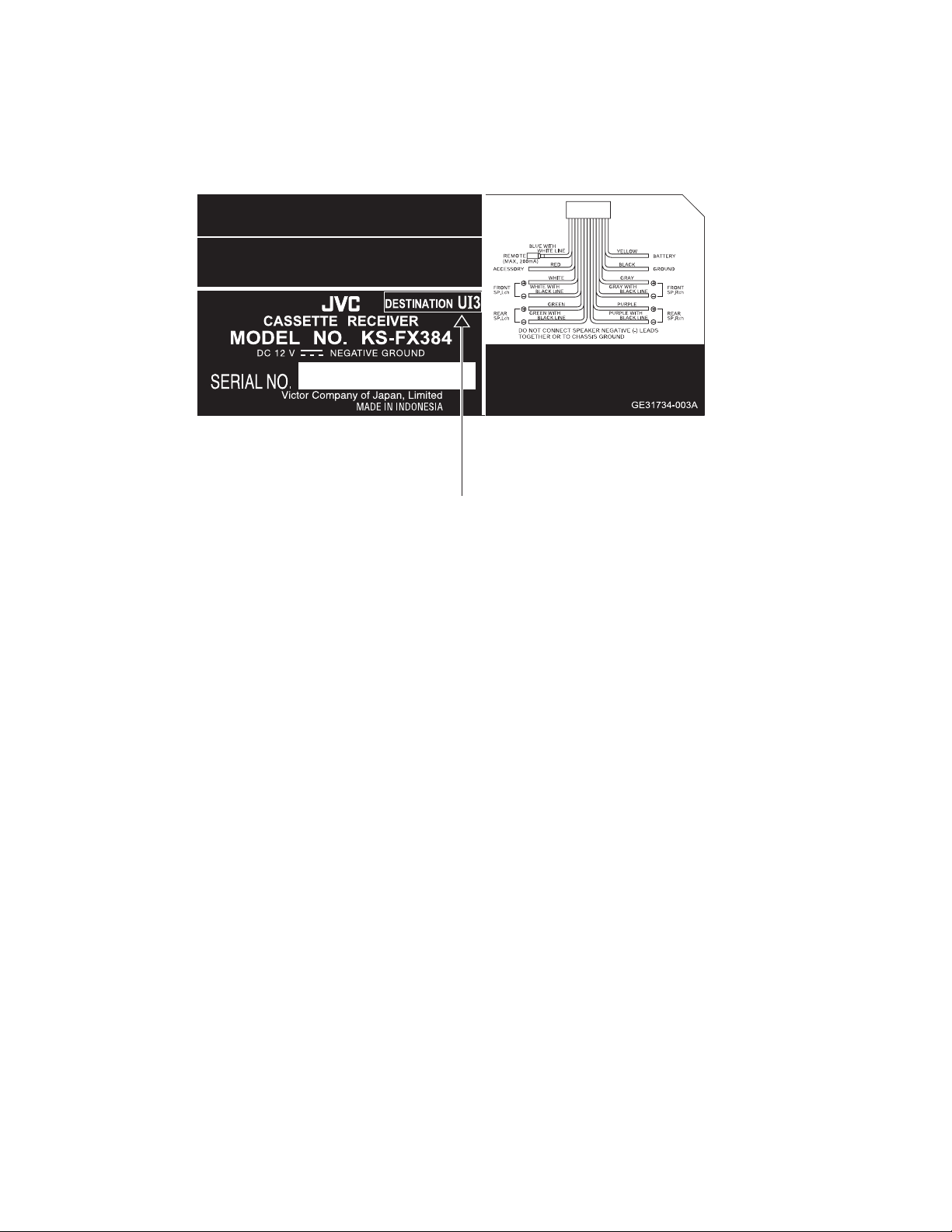
2.1 HOW TO IDENTIFY MODELS
2.1.1 NAME PLATE
SECTION 2
SPECIFIC SERVICE INSTRUCTIONS
Discernment sign
1-4 (No.MA182)
Page 5
SECTION 3
DISASSEMBLY
3.1 Main body
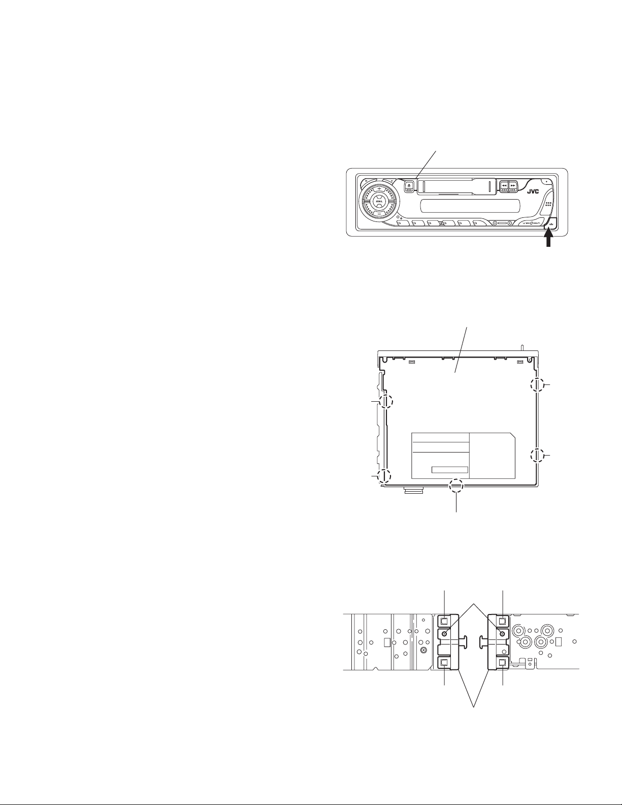
3.1.1 Removing the front panel assembly
(See Fig.1)
(1) Push the detach button and remove the front panel assem-
bly.
3.1.2 Removing the bottom cover
(See Fig.2)
• Prior to performing the following procedures, remove the front
panel assembly.
(1) Turn the body upside down.
(2) Insert a screwdriver under the joints to release the two
joints a on the left side, the two joints b on the right side and
the joint c on the back of the body, then remove the bottom
cover from the body.
CAUTION:
When releasing the joints using a screwdriver, do not damage
the board.
Joint a
Front panel assembly
Fig.1
Bottom cover
Detach button
Joint
b
3.1.3 Removing the front chassis assembly
(See Fig.3)
• Prior to performing the following procedures, remove the front
panel assembly and bottom cover.
(1) Remove the two screws A on each side of the body.
(2) Release the two joints d and the two joints e on the sides,
then remove the front chassis assembly toward the front.
Joint a
Joint c
Fig.2
Joint d Joint e
A
Joint d
Front chassis assembly
Fig.3
Joint e
Joint b
(No.MA182)1-5
Page 6
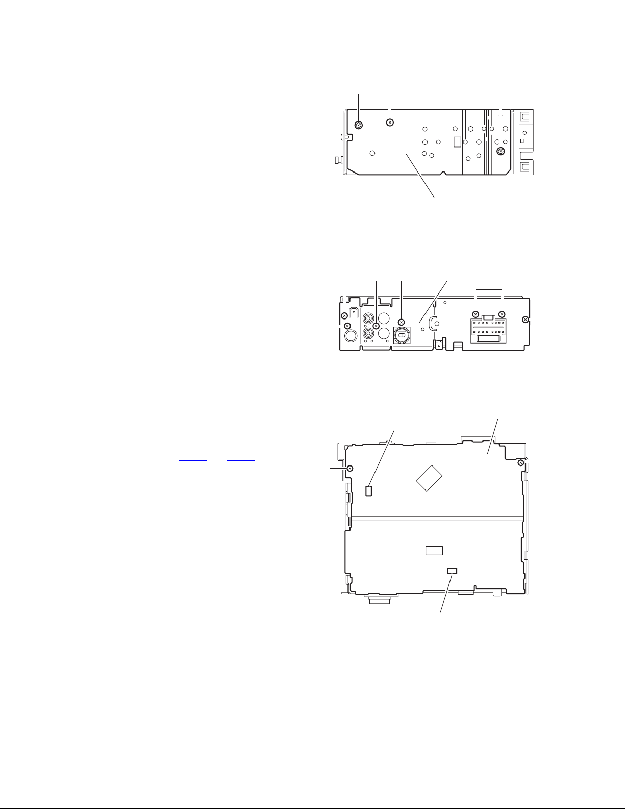
3.1.4 Removing the heat sink
(See Fig.4)
• Prior to performing the following procedure, remove the front
panel assembly.
(1) Remove the screw B and two screws C attaching the heat
sink on the left side of the body, and remove the heat sink.
3.1.5 Removing the rear panel
(See Fig.5)
• Prior to performing the following procedure, remove the front
panel assembly and bottom cover.
(1) Remove the two screws D, two screws E and three screws
F attaching the rear panel on the back of the body.
D
C
B
Heat sink
Fig.4
F
Rear panel
EF
C
3.1.6 Removing the main board
(See Fig.6)
• Prior to performing the following procedures, remove the front
panel assembly, bottom cover, front chassis assembly, heat
sink and rear panel.
(1) Remove the two screws G attaching the main board on the
top chassis.
(2) Disconnect the two connectors CN901
sion) or CN902 (UI3 version) on the main board from the
cassette mechanism assembly.
and CN721 (UI ver-
E
CN721(For UI version)
CN902(For UI3 version)
G
D
Fig.5
Main board
G
CN901
1-6 (No.MA182)
Fig.6
Page 7

3.1.7 Removing the cassette mechanism assembly
(See Fig.7)
• Prior to performing the following procedure, remove the front
panel assembly, bottom cover, front chassis assembly, heat
sink, rear panel and main board.
(1) Remove the four screws H attaching the cassette mecha-
nism assembly from the top chassis.
H
Cassette mechanism assembly
H
3.1.8 Removing the head amplifier board
(See Fig.8)
• Prior to performing the following procedures, remove the front
panel assembly, bottom cover, front chassis assembly, heat
sink, rear panel, main board and cassette mechanism assembly.
(1) Disconnect the wire from CJ901
board.
(2) Remove the one screw J attaching the head amplifier
board.
(3) Move the head amplifier board in the direction of the arrow
to release the two joints f, the head amplifier board can be
removed.
3.1.9 Removing the relay board
(See Fig.9)
• Prior to performing the following procedures, remove the front
panel assembly, bottom cover, front chassis assembly, heat
sink, rear panel, main board and cassette mechanism assembly.
(1) Disconnect the wire from CP722
(2) Remove the one screw K attaching the relay board.
(3) Move the relay board in the direction of the arrow to release
the joint g, the relay board can be removed.
on the head amplifier
on the relay board.
H
CJ901
Joint f
To head relay board
Top chassis
Fig.7
Head amplifier board
Joint f
J
Fig.8
Relay board
H
CP722
Joint g
Fig.9
K
(No.MA182)1-7
Page 8

3.1.10 Removing the mecha bracket
(See Fig.10)
• Prior to performing the following procedure, remove the front
panel assembly, bottom cover, front chassis assembly, heat
sink, rear panel, main board, cassette mechanism assembly,
head amplifier board and relay board.
(1) Remove the four screws L attaching the mecha bracket.
Mecha bracket
3.1.11 Removing the switch (LCD & key) board
(See Fig.11 to 13)
• Prior to performing the following procedures, remove the front
panel assembly.
(1) Remove the four screws M attaching the rear cover on the
back of the front panel assembly. (See Fig.11)
(2) Release the nine joints h, the front panel and the rear cover
become separate. (See Fig.12)
(3) Remove the switch board from the rear cover. (See Fig.13)
CAUTION:
Take care not to lose the springs.
L
L
Fig.10
M Front panel assembly
M
M M
L
L
Joint h
Fig.11
Joint h
Joint h
Fig.12
Switch (LCD & Key) board
Fig.13
1-8 (No.MA182)
Page 9

3.2 Cassette mechanism assembly
• Prior to performing the following procedures, remove the head
amplifier board, the relay board and the mechanism bracket.
3.2.1 Removing the direction switch board
(See Fig.1)
(1) Unsolder the three wires a on the direction switch board.
(2) Remove the one screw A attaching the direction switch
board.
3.2.2 Removing the FF / REW lever assembly
(See Fig.1)
(1) Remove the screw B attaching the FF / REW lever assem-
bly on the back of the cassette mechanism assembly.
(2) Remove the screw C on the upper side of the FF / REW
lever assembly.
(3) Lift and pull forward the FF / REW lever assembly to disen-
gage the joints b, c, d and e.
3.2.3 Reattaching the FF / REW lever assembly
(See Fig.1)
(1) Reattach the FF / REW lever assembly to the joint c on the
back of the chassis.
(2) Reattach the pinch-roller shaft e, the change lever d and
the return link e to the chassis.
C
FF / REW lever assembly
Joint c
3.2.4 Removing the playback head
(See Fig.2)
• Prior to performing the following procedure, remove the direc-
tion switch board and the FF / REW lever assembly.
(1) Remove the screw D attaching the playback head.
(2) Remove the C washer and pull out the FF roller.
(3) Remove the S support plate, the A arm spring (a) and (b),
the playback head.
ATTENTION:
The A arm spring (a) differs from the A arm spring (b).
3.2.5 Removing the pinch-roller (R) and (F) assembly
(See Fig.2)
• Prior to performing the following procedure, remove the direc-
tion switch board and the FF / REW lever assembly.
(1) Remove the P arm spring (f) in the pinch-roller (F) assem-
bly from the chassis.
(2) Remove the P arm spring (r) in the pinch-roller (R) assem-
bly from the chassis.
(3) Draw out the pinch roller (F) and (R) assembly from the
shaft.
ATTENTION:
The P arm spring (f) differs from the P arm spring (r).
ATTENTION:
The pinch roller (F) assembly differs from the pinch roller (R)
assembly.
Joint e
Joint d
A
Soldering a
Direction switch board
Fig.1
Pinch-roller (R) assembly
Shaft
Remove the P arm spring (r)
from the chassis.
Joint b
B
C washer
A arm spring (b)
FF roller
S support plate
D
Playback head
Pinch-roller (F) assembly
A arm spring (a)
Shaft
Remove the P arm spring (f)
from the chassis.
P arm spring (r)
P arm spring (f)
Fig.2
(No.MA182)1-9
Page 10

3.2.6 Removing the cassette hanger / cassette holder
(See Fig.3)
• Prior to performing the following procedure, remove the FF /
REW lever assembly.
(1) From the rear of the unit, bend the two tabs f outwards and
disengage the two joints g in the direction of the arrow.
(2) Push the eject lever and remove the cassette holder from
the playback head. Disengage the two joints h of the cassette hanger / cassette holder and the eject lever in the direction of the arrow.
(3) Lift the cassette hanger / cassette holder and disengage
the joint i of the return link and the eject lever.
Cassette holder
Cassette hanger
Chassis
Return link
Joint i
Eject lever
Joint h
Joint h
3.2.7 Removing the reel disc assembly
(See Fig.4)
• Prior to performing the following procedure, remove the FF /
REW lever assembly and the cassette hanger / cassette holder.
(1) Remove the C washer and pull out reel disc assembly.
ATTENTION:
Replace with a new C washer when reattaching.
3.2.8 Removing the motor assembly
(See Fig.5)
(1) Unsolder the two wires j on the motor assembly.
(2) Turn over the cassette mechanism assembly and remove
the main belt and the sub-belt from the motor pulley.
ATTENTION:
The main belt can now be removed.
(3) Remove the two screws G attaching the motor assembly.
Joint g
Flywheel (BF)
Tab f
C washer
C washer
Tab f
Fig.3
Fig.4
Main-belt
E
Joint g
Reel disc assembly
Motor assembly
Sub-belt
G
Motor pulley
1-10 (No.MA182)
Flywheel (BR)
Reel base assembly
E
Fig.5
G
Soldering j
E
F
Page 11

3.2.9 Removing the Flywheel (BF) and (BR) assembly
(See Fig.4 and 5)
• Prior to performing the following procedure, remove the cas-
sette hanger / cassette holder.
(1) From the upper side of the cassette mechanism assembly,
remove the C washer from each shaft of the flywheel (BF)
and (BR).
(2) Turn over the cassette mechanism assembly and remove
the main belt. Pull out the flywheel (BF) and (BR) downward respectively.
C washer
Reel disc assembly
C washer
Fig.4
Main-belt
Motor assembly
3.2.10 Removing the reel base assembly
(See Fig.5 and 6)
(1) Raise the part k of the reel base assembly slightly and re-
move the selector link (B) on the front side of the cassette
mechanism assembly by turning it as shown in Fig.6.
(2) Remove the three screws E and the one screw F on the
underside of the cassette mechanism assembly.
ATTENTION:
The reel base assembly is not repairable. Handle with care.
Pinch-roller (R) assembly
k
Selector link (B).
Turn the selector link (B).
Fig.6
Inside of the reel base assembly
Flywheel (BF)
Flywheel (BR)
Sub-belt
E
Reel base assembly
E
Fig.5
Motor pulley
G
E
F
G
Soldering j
Fig.7
(No.MA182)1-11
Page 12

3.2.11 Removing the mute switch board (See Fig.8)
(1) Unsolder the two wires l on the mute switch board on the
back of the cassette mechanism assembly.
(2) Remove the screw H attaching the mute switch board.
3.2.12 Removing the power switch
(See Fig.9)
• Prior to performing the following procedure, remove the motor
assembly.
(1) Unsolder the two wires m on the power switch on the side
of the cassette mechanism assembly.
(2) Remove the screw I attaching the power switch.
Cassette mechanism assembly
Soldering l
H
Fig.8
Soldering m
I
Cassette mechanism assembly
Power switch
Fig.9
Rower switch
Motor assembly
Mute switch board
1-12 (No.MA182)
Page 13

SECTION 4
ADJUSTMENT
4.1 Adjustment method
Test instruments required for adjustment
(1) Digital oscilloscope (100MHz)
(2) Frequency counter meter
(3) Electric voltmeter
(4) Wow & flutter meter
(5) Test tapes
VT724:for DOLBY level measurement
VT739:For playback frequency measurement
VT712:For wow flutter & tape speed measurement
VT703:For head azimuth measurement
(6) Torque gauge:Cassette type for CTG-N(Mechanism ad-
justment)
Measuring conditions (Amplifier section)
Power supply voltage :DC14.4V (11V to 16V allowance)
Load impedance: 4Ω(4Ωto 8Ωallowance)
Line out level/Impedance :2.0V/20kΩload (250 nWb/m)
Standard volume position
Balance and Bass, Treble volume, Fader
:Center (Indication "0")
Loudness, Dolby NR, Sound, Cruise : Off
Volume position is about 2V at speaker output with following
conditions, Playback the test tape VT721.
AM mode 999kHz/62dB, INT/400Hz, 30% modulation
signal on receiving.
FM mono mode 97.9MHz/66dB, INT/400Hz, 22.5kHz devia-
tion pilot off mono
FM stereo mode 1kHz, 67.5kHz dev. pilot 7.5kHz dev.
Output level:0dB (1µV,50Ω/open terminal)
(No.MA182)1-13
Page 14

Information for using a car audio service jig
(1) We're advancing efforts to make our extension cords common for all car audio products.
Please use this type of extension cord as follows.
(2) As a U-shape type top cover is employed, this type of extension cord is needed to check operation of the mechanism assembly
after disassembly.
(3) Extension cord : EXTKSRT002-6P ( 6 pin extension cord ) For connection bn etween mechanism assembly and main board.
(4) Check for mechanism driving section such as motor ,etc.
Disassembly method
(1) Remove the front panel assembly.
(2) Remove the bottom cover.
(3) Remove the front chassis assembly.
(4) Remove the heat sink.
(5) Remove the rear panel.
(6) Remove the main board.
(7) Reattach the heat sink with the screw B and two screws C. (Refer to Disassembly method.)
(8) Reattach the rear panel with the screw F. (Refer to Disassembly method.)
(9) Reattach the front chassis assembly with the screw A. (Refer to Disassembly method.).
(10) Reattach the front panel assembly.
(11) Confirm that current is being carried by connecting an extension cord jig.
Note:
Available to connect to the CJ701
CAUTION:
Be sure to attach the heat sink and rear panel on the power amplifier IC and regulator IC of a main board when supplying
the power.
If voltage is applied without attaching those parts, the power amplifier IC and regulator IC will be destroyed by heat.
connector when installing the front panel.
EXTKSRT002-6P
Front Panel assembly
Cassette mechanism
Extension cord
: EXTKSRT002-6P
Main board
1-14 (No.MA182)
Page 15

4.2 Arrangement of Adjusting & Test points
Cassette mechanism
(Surface)
Tape speed adjust
Motor assembly
Playback head
Azimuth screw
Head section view
Head azimuth screw
Height adjusting screw c
Fixed screw
Playback head
Height adjusting screw a
Height adjusting screw b
(No.MA182)1-15
Page 16

Item
Conditions
Adjustment and Confirmation methods
S.Values Adjust
Head
1.
azimuth
adjustment
Test tape:
SCC-1659
VT703 (10kHz)
Test tape:
VT724 (1kHz)
VT703 (10kHz)
VT721 (315Hz)
Head height adjustment
Adjust the azimuth directly. When you
adjust the height using a mirror tape,
remove the cassette housing from the
mechanism chassis.
After installing thecassette housing,
perform the azimuth adjustment.
Load the SCC-1659 mirror tape. Adjust with
1.
height adjustment screw A and azimuth
adjustment screw B so that line A of the
mirror tape runs in the center between Lch
and Rch in the reverse play mode.
After switching from REV to FWD then to
2.
REV, check that the head position set in
procedure 1 is not changed. (If the position
has shifted, adjust again and check.)
Adjust with azimuth adjustment screw B so
3.
that line B of the mirror tape runs in the
center between Lch and Rch in the forward
play mode.
Head azimuth adjustment
Load VT724 (1kHz) and play it back in
1.
the reverse play mode.
Set the Rch output level to max.
Load VT703 (10kHz) and play it back in
2.
the forward play mode. Adjust the Rch
and Lch output levels to max, with
azimuth adjustment screw B. In this case,
the phase difference should be within 45 .
Engage the reverse mode and adjust the
3.
output level to max, with azimuth
adjustment screw C.
(The phase difference should be 45 or
more.)
When switching between forward and
4.
reverse modes, the difference between
channels should be within 3dB. (Between
FWD L and R, REV L and R.)
A line
Head shield
The head is at low position
during.
B line
Head shield
The head is at High position
during REV.
Output
level:
Maximum
PBHead
FWD Adj B
REV Adj C
(0 ) (45 )
HEIGHT Adj A
phase
2.
Tape speed
and wow
flutter
confirmation
3.
Play back
frequency
response
confirmation
1-16 (No.MA182)
When VT721 (315Hz) is played back,
5.
the level difference between channels
should be within 1.5dB.
Test tape: VT712
(3kHz)
Test tape: VT724
(1kHz)
VT739
(63Hz / 1kHz / 10kHz)
The tuner section is of an adjustment-freedesign. In case the tuner is in trouble, replace the tuner pack.
Check to see if the reading of the F, counter /
1.
wow flutter meter is within 3015Hz to 3045Hz
(FWD/ REV), and less than 0.35% (JIS RMS).
In case of out of specification, adjust the
2.
motor with a built-in volume resistor.
Play test tape VT724, and set the volume
1.
position at 2V.
Play test tape VT739 and confirm.
2.
1kHz / 10kHz: -1 3dB,
1kHz / 63Hz: 0 3dB,
When 10kHz is out of specification, it will be
3.
necessary to read adjust the azimuth.
Tape speed:
3015Hz
to 3045Hz
Wow
flutter: less
than 0.35%
Speaker out
1kHz / 63Hz
: 0 3dB
1kHz / 10kHz
: -1 3dB
Built-in volume
resistor
Page 17

5.1 16 PIN CORD DIAGRAM
SECTION 5
TROUBLESHOOTING
8
7
6
5
4
3
2
1
BK
RD
NC
BL/WH
WH
GN
VI
GY
WH/BK
GN/BK
VI/BK
GY/BK
16 YL
8 BK
7 RD ACC
5 BL/WH REMOTE
4 WH
12 WH/BK
3 GN
11 GN/BK RL-
2 VI RR+
10 VI/BK
1 GY FR+
YL
NC
NC
NC
16
15
14
13
12
11
10
9
MEMORY
GND
FL+
FL-
RL+
RR-
BK
RD
BL
WH
Black
Red
Blue
White
GN
VI
GY
YL
Green
Violet
Gray
Yellow
9 GY/BK
RR
FR
FL
RL
Rear Right
Front Right
Front Left
Rear Left
FR-
REMOTE
ACC
MEMORY
GND
Remote out
ACC Line
Memory Backup Battery +
Ground
(No.MA182)1-17
Page 18

Victor Company of Japan, Limited
AV & MULTIMEDIA COMPANY CAR ELECTRONICS CATEGORY 10-1,1chome,Ohwatari-machi,Maebashi-city,371-8543,Japan
(No.MA182)
Printed in Japan
VPT
 Loading...