

Page 1
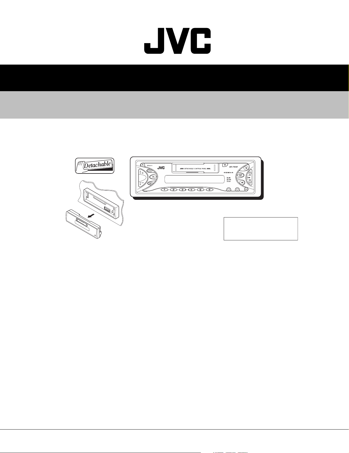
KS-F545
SERVICE MANUAL
CASSETTE RECEIVER
4982820034
KS-F545
MO
RPT
SCM
MODE
Area Suffix
EE ------- Russian Federation
TABLE OF CONTENTS
1 Important Safety Precautions . . . . . . . . . . . . . . . . . . . . . . . . . . . . . . . . . . . . . . . . . . . . . . . . . . . . . . . . . . . 1-2
2 Disassembly method . . . . . . . . . . . . . . . . . . . . . . . . . . . . . . . . . . . . . . . . . . . . . . . . . . . . . . . . . . . . . . . . . . 1-3
3 Adjustment. . . . . . . . . . . . . . . . . . . . . . . . . . . . . . . . . . . . . . . . . . . . . . . . . . . . . . . . . . . . . . . . . . . . . . . . . . 1-18
4 Description of major ICs. . . . . . . . . . . . . . . . . . . . . . . . . . . . . . . . . . . . . . . . . . . . . . . . . . . . . . . . . . . . . . . 1-22
COPYRIGHT © 2003 VICTOR COMPANY OF JAPAN, LTD.
No.49828
2003/4
Page 2

KS-F545
1.1 Safety Precautions
SECTION 1
Important Safety Precautions
!
Burrs formed during molding may be left over on some parts of the chassis. Therefore,
pay attention to such burrs in the case of preforming repair of this system.
1-2 (No.49828)
Page 3
SECTION 2
Disassembly method
2.1 Main body
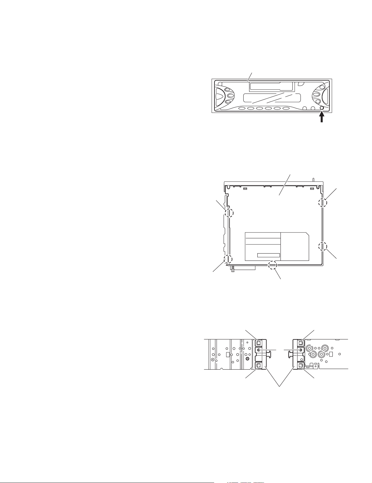
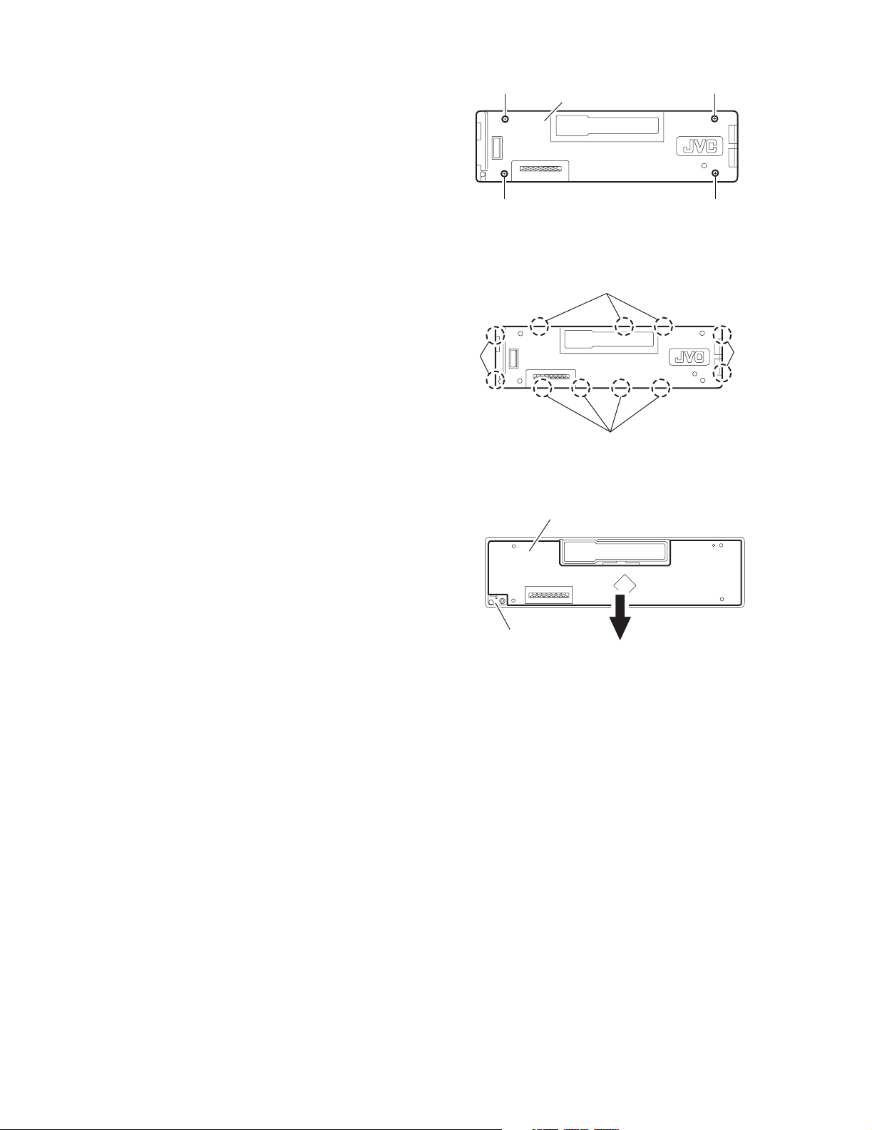
2.1.1 Removing the front panel assembly
(See Fig.1)
(1) Press the release button and remove the front panel as-
sembly.
2.1.2 Removing the bottom cover
(See Fig.2)
(1) Turn the main body upside down.
(2) Insert a screwdriver under the joints to release the two
joints a on the left side, two joints b on the right side and
joint c on the back side of the main body, then remove the
bottom cover from the main body.
CAUTION:
When releasing the joints using a screwdriver, do not damage
the main board.
Joint a
Front panel assembly
Fig.1
Bottom cover
Release button
Joint
KS-F545
b
2.1.3 Removing the front chassis
(See Fig.3)
• Prior to performing the following procedures, remove the front
panel assembly and bottom cover.
(1) Remove the screw A on the both sides of the main body.
(2) Release the two joints d and two joints e on the both sides
of the main body, then remove the front chassis toward the
front.
Joint a
Joint c
Fig.2
Joint d
Joint e
A
Joint d Joint e
Front chassis
Fig.3
Joint b
(No.49828)1-3
Page 4
KS-F545
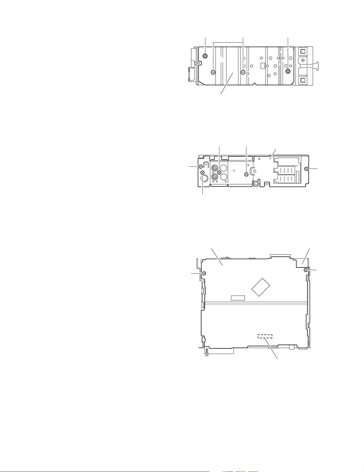
2.1.4 Removing the heat sink
(See Fig.4)
• Prior to performing the following procedure, remove the front
panel assembly.
(1) Remove the two screws B and two screws C attaching the
heat sink on the left side of the main body, and remove the
heat sink.
2.1.5 Removing the rear panel
(See Fig.5)
• Prior to performing the following procedure, remove the front
panel assembly and bottom cover.
(1) Remove the two screws D, two screws E and screw F at-
taching the rear panel on the back side of the main body.
D
CB C
Heat sink
Fig.4
EF
Rear panel
E
Fig.5
D
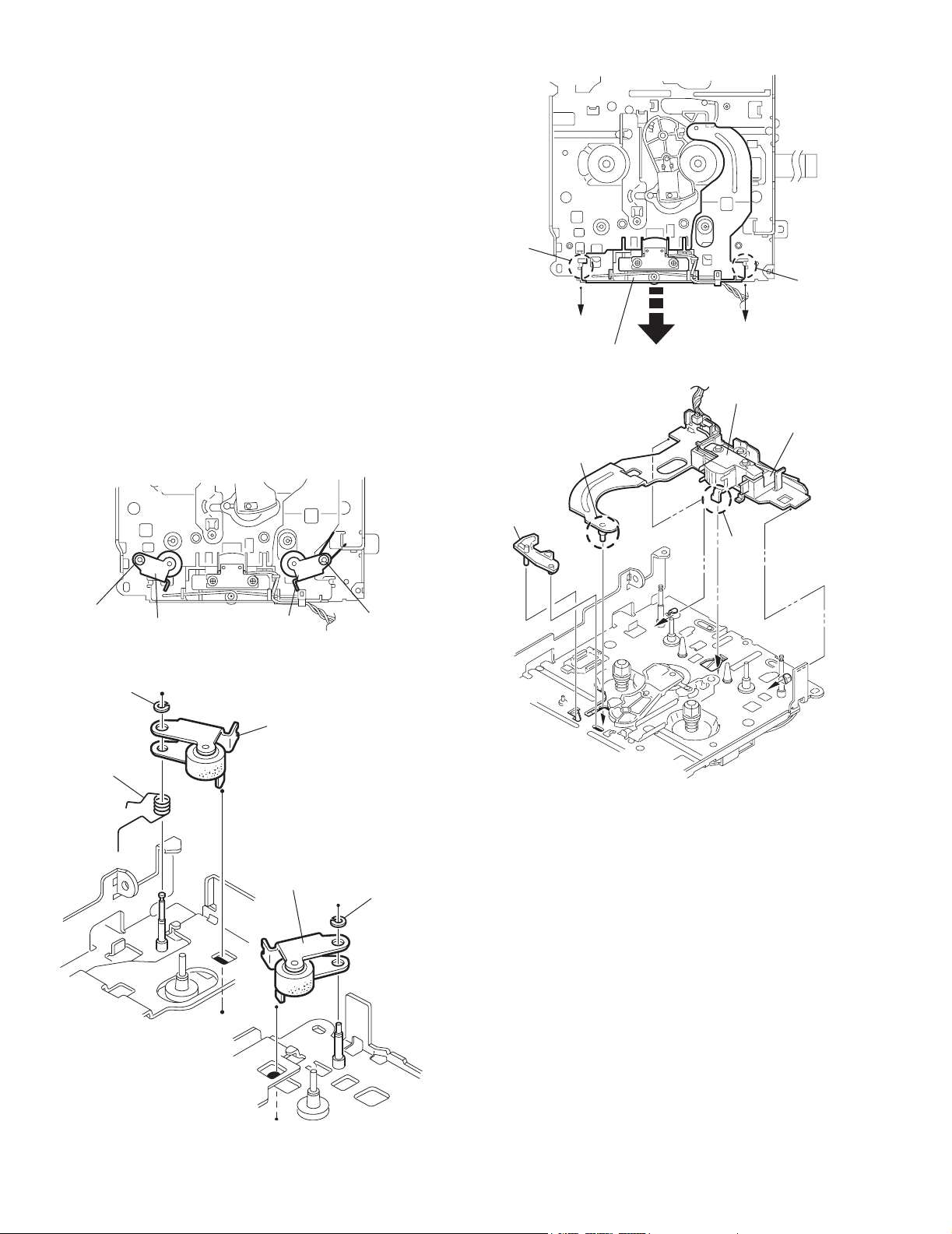
2.1.6 Removing the main board
(See Fig.6)
• Prior to performing the following procedures, remove the front
panel assembly, bottom cover, front chassis, heat sink and
rear panel.
(1) Remove the two screws G attaching the main board on the
top chassis.
(2) Disconnect the connectors CP401 on the main board from
the cassette mechanism assembly.
G
Main board
Top chassis
G
CP401
Fig.6
1-4 (No.49828)
Page 5
KS-F545
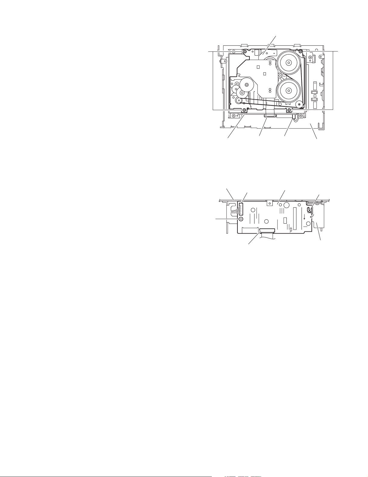
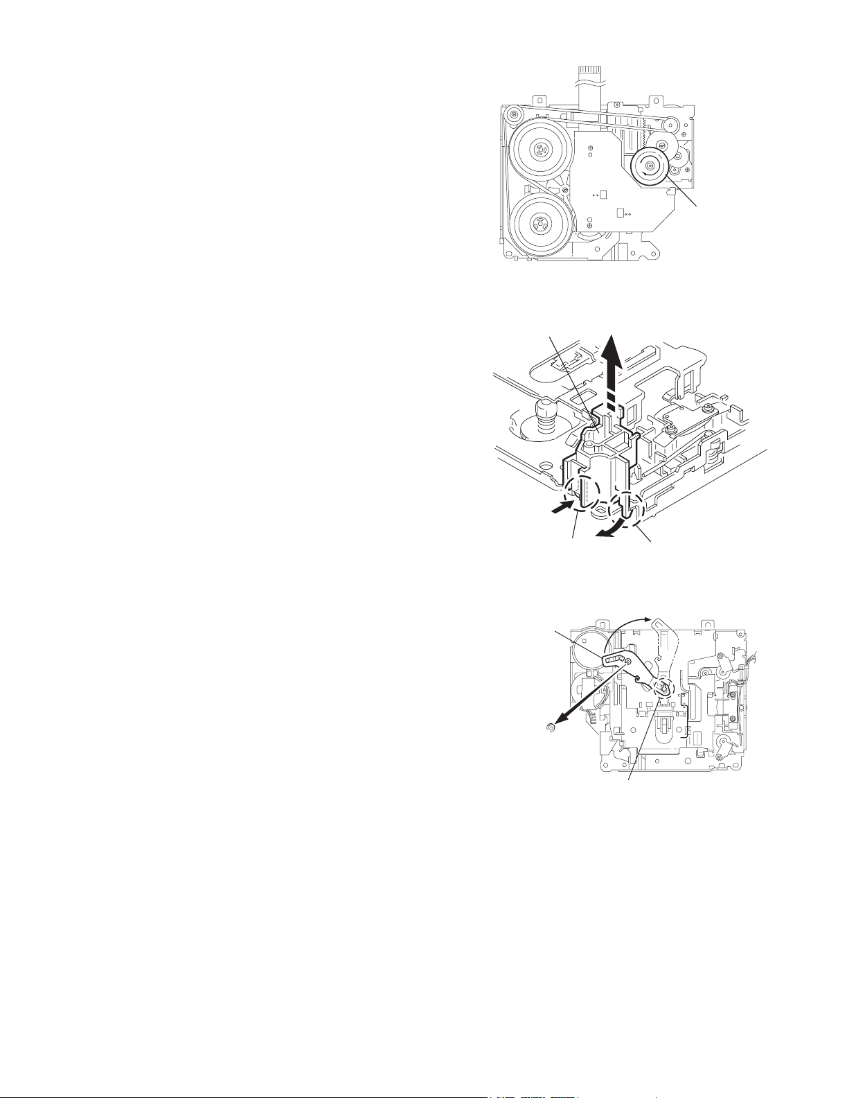
2.1.7 Removing the cassette mechanism assembly
(See Fig.7)
• Prior to performing the following procedures, remove the front
panel assembly, bottom cover, front chassis, heat sink, rear
panel and main board.
(1) Disconnect the wire from the connector CN402 on the
mecha board.
(2) Disconnect the card wire from the connector CN403 on the
mecha board.
(3) Remove the four screws H attaching the cassette mecha-
nism assembly from the top chassis.
2.1.8 Removing the mecha board
(See Fig.8)
• Prior to performing the following procedures, remove the front
panel assembly, bottom cover, front chassis, heat sink, rear
panel and main board.
(1) Disconnect the wire from the connector CN402 on the
mecha board.
(2) Disconnect the card wire from the connector CN403 on the
mecha board.
(3) Remove the screw J attaching the mecha board.
(4) Bend the hook f in the direction of the arrow 1 and move the
mecha board in the direction of the arrow 2.
(5) Remove the mecha board from the mecha bracket (L) of
the top chassis.
H
Mecha board
Top chassis
J
Cassette mechanism assembly
CN403
CN402
CN403
CN402
Fig.7
Mecha board
Fig.8
H
Top chassis
Hook f
1
2
Mecha bracket (L)
(No.49828)1-5
Page 6
KS-F545
2.1.9 Removing the front board
(See Fig.9 to 11)
• Prior to performing the following procedures, remove the front
panel assembly.
(1) Remove the four screws K attaching the rear cover on the
back side of the front panel assembly. (See Fig.9.)
(2) Release the eleven joints g, the front panel assembly and
the rear cover become separate. (See Fig.10.)
(3) Remove the front board from the front panel assembly.
(See Fig.11.)
K
Rear cover
K
K K
Fig.9
g
Joints
Joints g
Front panel assembly
Joints g
Joints g
Fig.10
Front board
Fig.11
1-6 (No.49828)
Page 7
2.2 Cassette mechanism assembly
r
REFERENCE:
Prior to performing the following procedures, turn the mode
gear on the bottom of the body until the respective part comes
to the EJECT position (Refer to Fig.1).
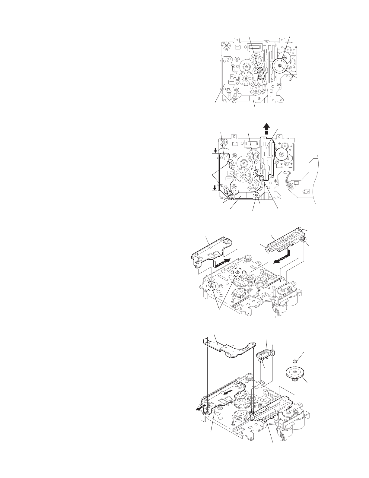
2.2.1 Removing the cassette guide
(See Fig.2)
(1) Turn the mode gear to set to RVS play or subsequent
mode.
(2) Remove the cassette guide from the main chassis while re-
leasing each two joint tabs a in the direction of the arrow.
KS-F545
Mode gea
Fig.1
Cassette guide
2.2.2 Removing the load arm
(See Fig.3)
(1) Remove the E-washer attaching the load arm.
(2) Move the load arm in the direction of the arrow and release
the joint b on the cassette catch.
Load arm
E-washer
Tab a
Tab a
Fig.2
Joint b
Fig.3
(No.49828)1-7
Page 8
KS-F545
r
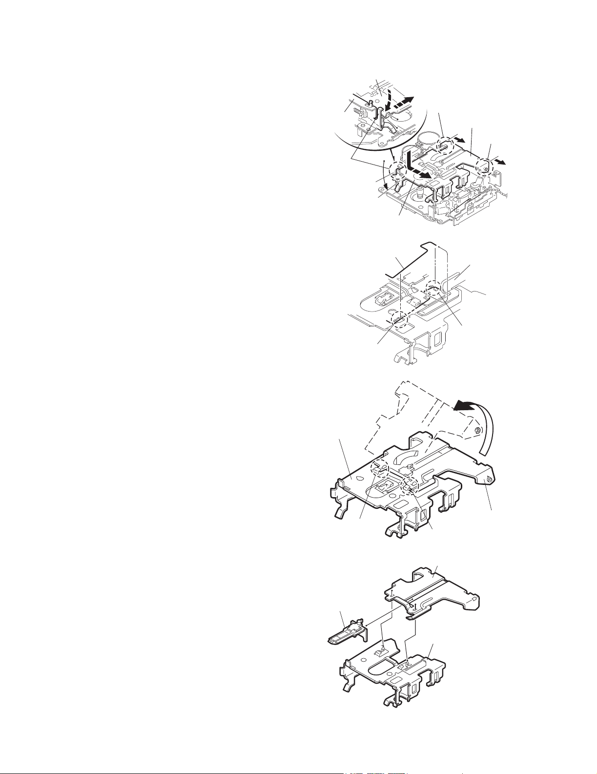
2.2.3 Removing the cassette hanger assembly / cassette holder
(See Fig.4 to 7)
(1) Check the mode is set to EJECT. Push down the front part
of the cassette holder and move in the direction of the arrow to release the joint c.
(2) Move the rear part of the cassette hanger assembly in the
direction of the arrow to release it from the two joint bosses
d.
(3) Release the holder stabilizer spring from the hooks e and
f, then pull out from the cassette hanger assembly.
(4) Bring up the rear side of the cassette hanger assembly to
release the joint g and h.
(5) Pull out the cassette catch from the cassette hanger as-
sembly.
Cassette holder assembly
Side bracket
Joints c
Cassette holder assembly
Fig.4
Boss d
Cassette hanger
assembly
Boss d
Cassette stabilizer spring
Hook e
Cassette holder
assembly
Hook g
Cassette hange
assembly
Hook f
Fig.5
Cassette hanger
assembly
Hook h
Fig.6
Cassette hanger assembly
1-8 (No.49828)
Cassette catch
Cassette holder assembly
Fig.7
Page 9
KS-F545
2.2.4 Removing the side bracket assembly
(See Fig.8 to 10)
(1) Remove the screw A attaching the side bracket assembly.
(2) Detach the front side of the side bracket assembly upward
and pull out forward to release the joint i and j in the rear.
CAUTION:
When reassembling, make sure that the boss k of the
main chassis is set in the notch of the load rack under the
side bracket assembly. Do not reattach the load rack on
the boss k.
CAUTION:
After reattaching the side bracket assembly, confirm operation.
Side bracket assembly
Joint i
Joint j
A
Side bracket assembly
Fig.8
Side bracket assembly
Joint i
Joint j
Load rack
Load rack
Boss k
Fig.9
Boss k
Fig.10
(No.49828)1-9
Page 10
KS-F545
r
2.2.5 Removing the pinch arm (F) assembly
(See Fig.11 and 12)
(1) Remove the polywasher and pull out the pinch arm (F) as-
sembly.
(2) Remove the compulsion spring.
2.2.6 Removing the pinch arm (R) assembly
(See Fig.11 and 12)
(1) Remove the polywasher and pull out the pinch arm (R) as-
sembly.
2.2.7 Removing the slide chassis assembly
(See Fig.13 and 14)
REFERENCE:
It is not necessary to remove the head and the tape guide.
(1) Move the slide chassis assembly in the direction of the ar-
row to release the two joints l and remove from the main
chassis.
(2) Remove the rack link.
CAUTION:
When reassembling, first reattach the rack link, and next
fit the boss m and hook n of the slide chassis assembly
to the hole of the main chassis, and engage the two joints
l.
Joint l
Joint l
Slide chassis assembly
Fig.13
Head
Tape guide
Boss m
Polywasher
Polywasher
Compulsion
spring
Pinch arm
(R) assembly
Pinch arm
(F) assembly
Fig.11
Pinch arm (F) assembly
Pinch arm
(R) assembly
Rack link
Hook n
Polywashe
Fig.14
Polywasher
1-10 (No.49828)
Fig.12
Page 11
KS-F545
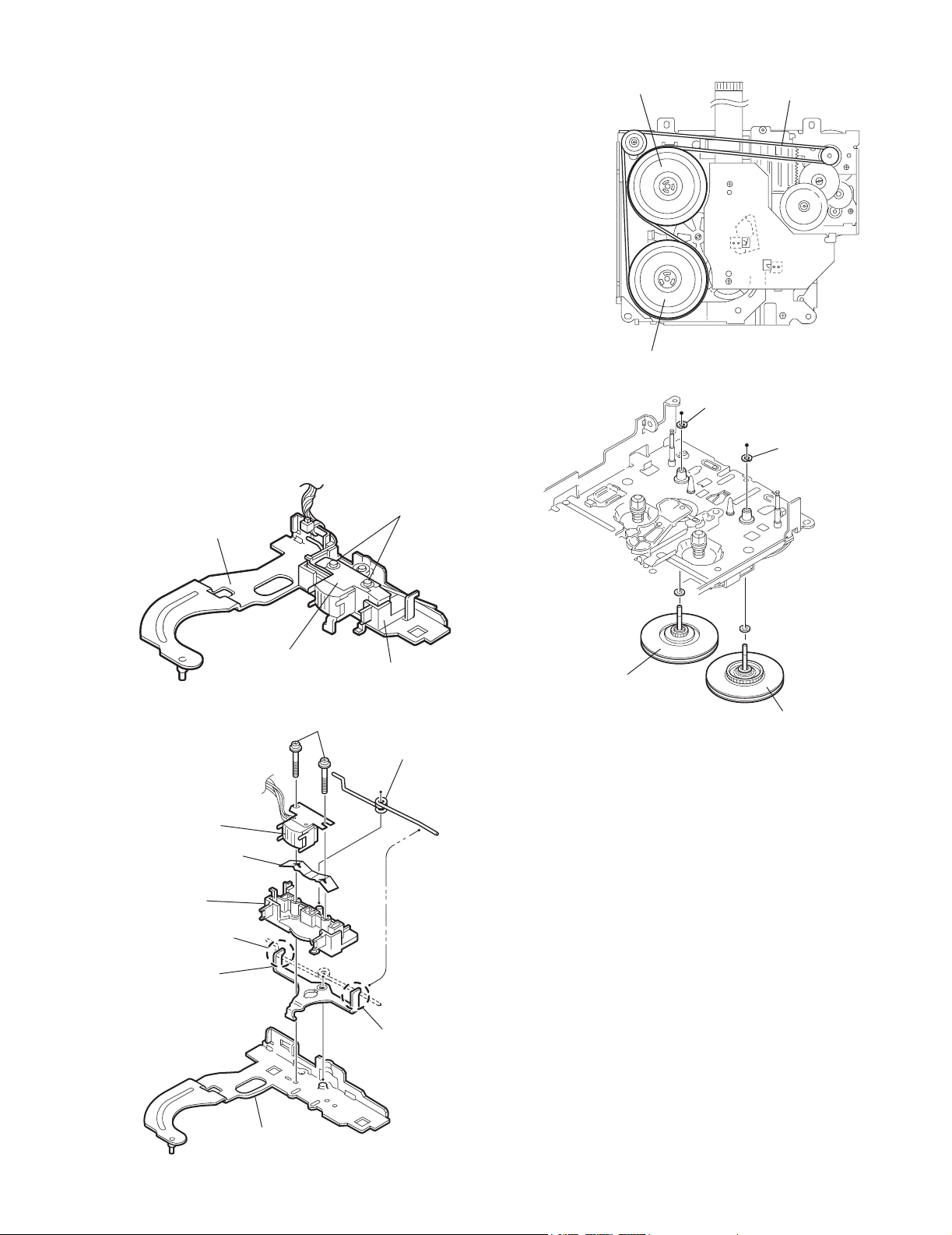
2.2.8 Removing the head / tape guide
(See Fig.16 and 17)
REFERENCE:
It is not necessary to remove the slide chassis assembly.
(1) Remove the band attaching the wire to the head.
(2) Remove the two screws B, the head and the head support
spring.
(3) Remove the pinch arm spring from the tape guide.
(4) Remove the tape guide and the pinch spring arm.
CAUTION:
When reattaching the pinch arm spring, set both end of
it to the pinch spring arm (remarked o).
CAUTION:
When reattaching the head, set the wires into the groove
of the tape guide (Fig.16).
2.2.9 Removing the flywheel assembly (F) & (R)
(See Fig.18 and 19)
REFERENCE:
It is not necessary to remove the slide chassis assembly.
(1) Remove the belt at the bottom.
(2) Remove the two polywashers on the upper side.
(3) Pull out each flywheel assembly downward.
B
Slide chassis assembly
Flywheel assembly (F)
Flywheel assembly (R)
Belt
Fig.17
Polywasher
Polywasher
Head
Head support spring
Tape guide
o
Pinch spring arm
Head
Fig.15
Tape guide
B
Pinch arm spring
Flywheel assembly (F)
Flywheel assembly (R)
Fig.18
o
Slid chassis assembly
Fig.16
(No.49828)1-11
Page 12
KS-F545
r
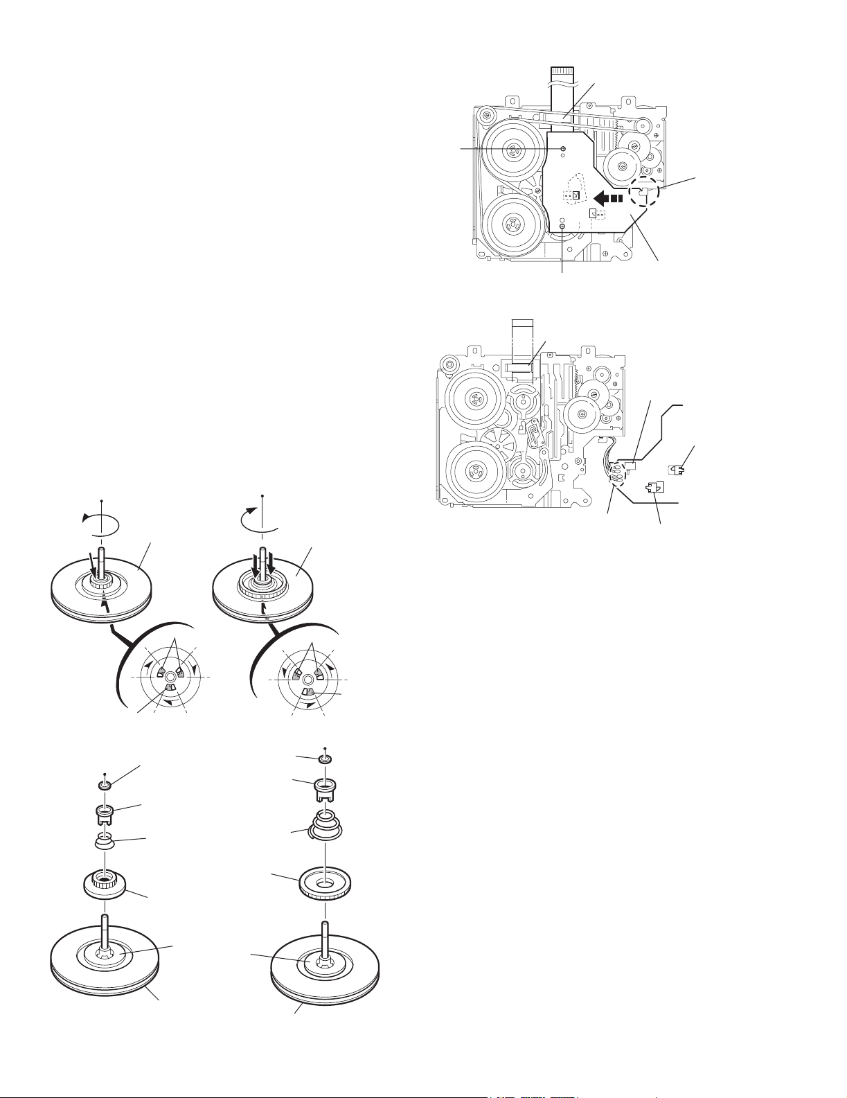
2.2.10 Disassembling the flywheel assembly (F)
(See Fig.19 and 20)
(1) Push and turn counterclockwise the spring holder (F) to re-
lease the three joints p on the bottom of the flywheel.
(2) The spring holder (F), the TU spring and the friction gear
play come off.
(3) Remove the polywasher and felt.
2.2.11 Disassembling the flywheel assembly (R)
(See Fig.19 and 20)
(1) Push and turn clockwise the spring holder (R) to release
the three joints q on the bottom of the flywheel.
(2) The spring holder (R), the FF spring and the friction gear
FF come off.
(3) Remove the polywasher and the felt.
2.2.12 Removing the reel board
(See Fig.21 and 22)
(1) Remove the two screws C attaching the reel board.
(2) Move the reel board in the direction of the arrow to release
the joint r.
(3) Unsolder the wires if necessary.
CAUTION:
When reattaching, confirm operation of the MODE
switch and the ST-BY switch.
The mode position between EJECT and ST-BY is optimum for reattaching.
Connect the card wire extending from the reel board to
the FFC pad before reattaching the reel board.
FFC pad
C
Joint
Reel board
C
Fig.21
FFC pad
CT-1 switch
MODE switch
Flywheel
assembly (F)
Joint p
Joints p
Fig.19
Polywasher
Spring holder (R)
Spring holder (F)
TU spring
Friction gear FF
Friction gear play
Polywasher
FF spring
Flywheel
assembly (R)
Joints q
Joint q
Soldering
ST-BY switch
Fig.22
Flywheel assembly (F)
1-12 (No.49828)
Felt
Felt
Flywheel assembly (R)
Fig.20
Page 13
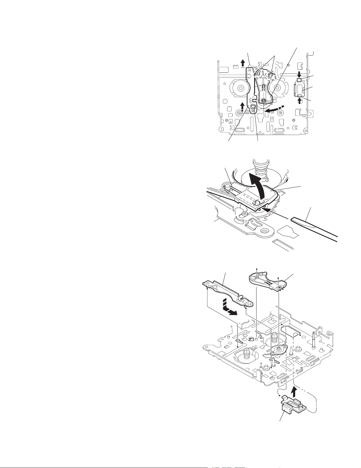
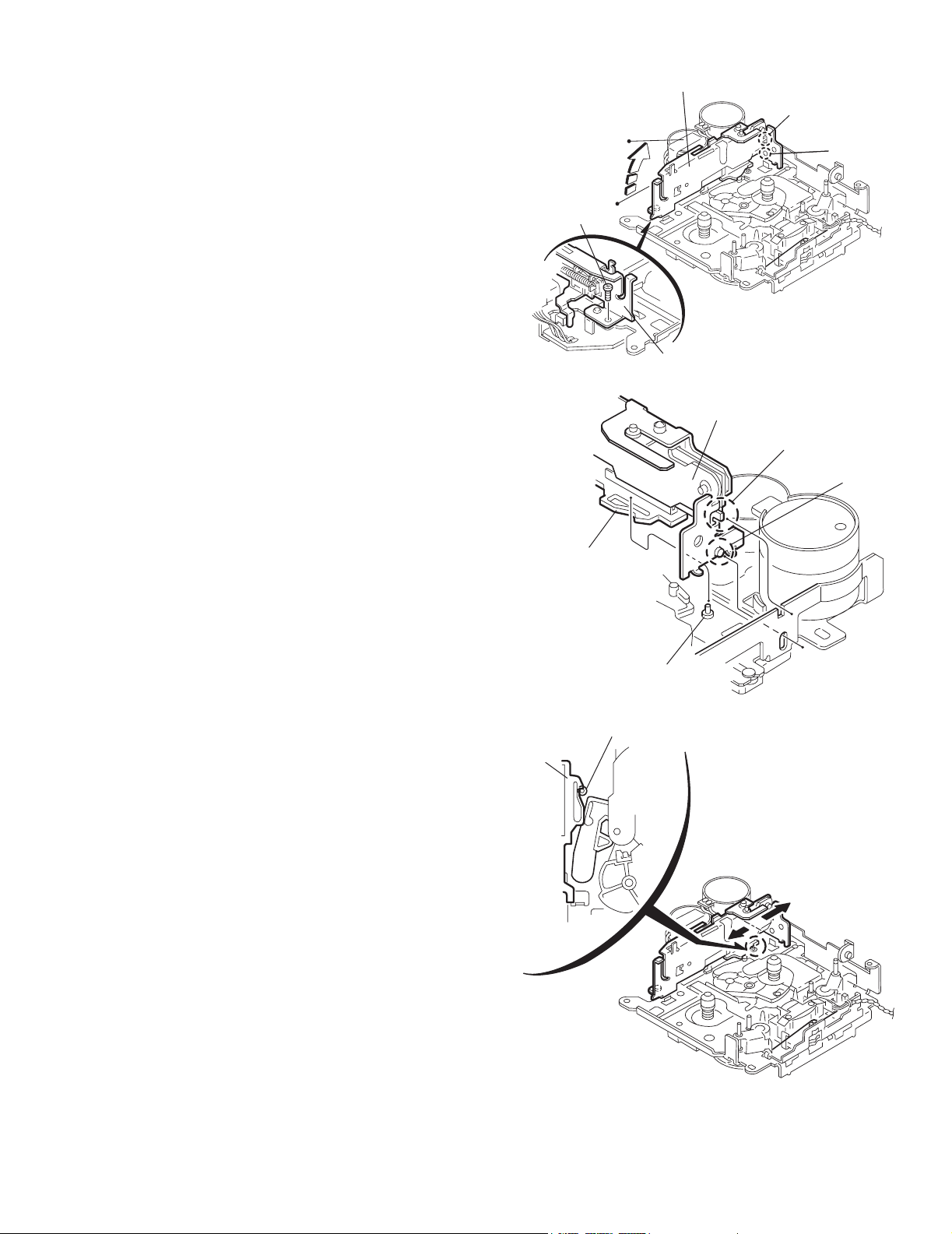
2.2.13 Removing the gear base arm / gear base link assembly
(See Fig.23 to 25)
(1) Move the gear base arm in the direction of the arrow.
(2) Insert a slotted screwdriver to the gear base spring under
the gear base arm, and release the gear base arm upward
from the boss on the gear base assembly.
(3) Remove the gear base arm from the main chassis while re-
leasing the two joints s.
(4) Move the gear base link assemby in the direction of the ar-
row to release the two joints t.
REFERENCE:
When reattaching the gear base arm, make sure that the
boss on the gear base assembly is inside the gear base
spring.
2.2.14 Removing the FFC pad
(See Fig.25 and 27)
(1) Push each joint hook u of the FFC pad and remove toward
the bottom.
Gear base
link assembly
Gear base spring
Joint t
KS-F545
Gear base arm
Joints s
Hook u
FFC pad
Hook u
Joint t
Fig.23
Gear base link
assembly
Gear base arm
Screwdriver
Fig.24
Gear base arm
FFC pad
Fig.25
(No.49828)1-13
Page 14
KS-F545
r
r
2.2.15 Removing the mode gear
(See Fig.26 and 29)
(1) Remove the polywasher on the bottom and pull out the
mode gear.
2.2.16 Removing the mode switch actuator
(See Fig.26, 27 and 29)
(1) Pull out the mode switch actuator at the bottom.
REFERENCE:
When reattaching the mode switch actuator to the main
chassis, make sure to set on the shaft and insert v into
the slot w.
2.2.17 Removing the direction link / direction plate
(See Fig.27 to 29)
(1) Remove the polywasher attaching the direction link.
(2) Bring up the direction link to release the three joints x, y
and z at a time.
(3) Move the direction plate in the direction of the arrow to re-
lease the two joints a’.
REFERENCE:
When reattaching the direction plate, engage the two
joints a’ and move in the direction of the arrow (Refer to
Fig.28).
REFERENCE:
When reattaching the direction link, move the direction
plate in the direction of the arrow and engage the three
joint x, y and z at a time (Refer to Fig.29).
2.2.18 Removing the mode rack assembly
(See Fig.27 and 28)
(1) Move the mode rack assembly in the direction of the arrow
to release the two joints b’ and the joint c’.
REFERENCE:
When reattaching, set the two b’ on the bottom of the
mode rack assembly into the slots of the main chassis
and move in the direction of the arrow (See Fig.28).
Direction plate
Direction plate
Joints a'
Joint z
Direction link
Direction plate
Mode switch actuator
Direction link
Fig.26
Slot w
Joint y
Polywasher
Fig.27
Mode rack assembly
Joint b'
Mode gear
Polywashe
Mode rack assembly
Joint x
Joint b'
Joint c'
1-14 (No.49828)
Joints a'
Fig.28
Direction link
Mode switch actuator
Polywasher
v
Mode gea
Direction plate
Mode rack assembly
Fig.29
Page 15
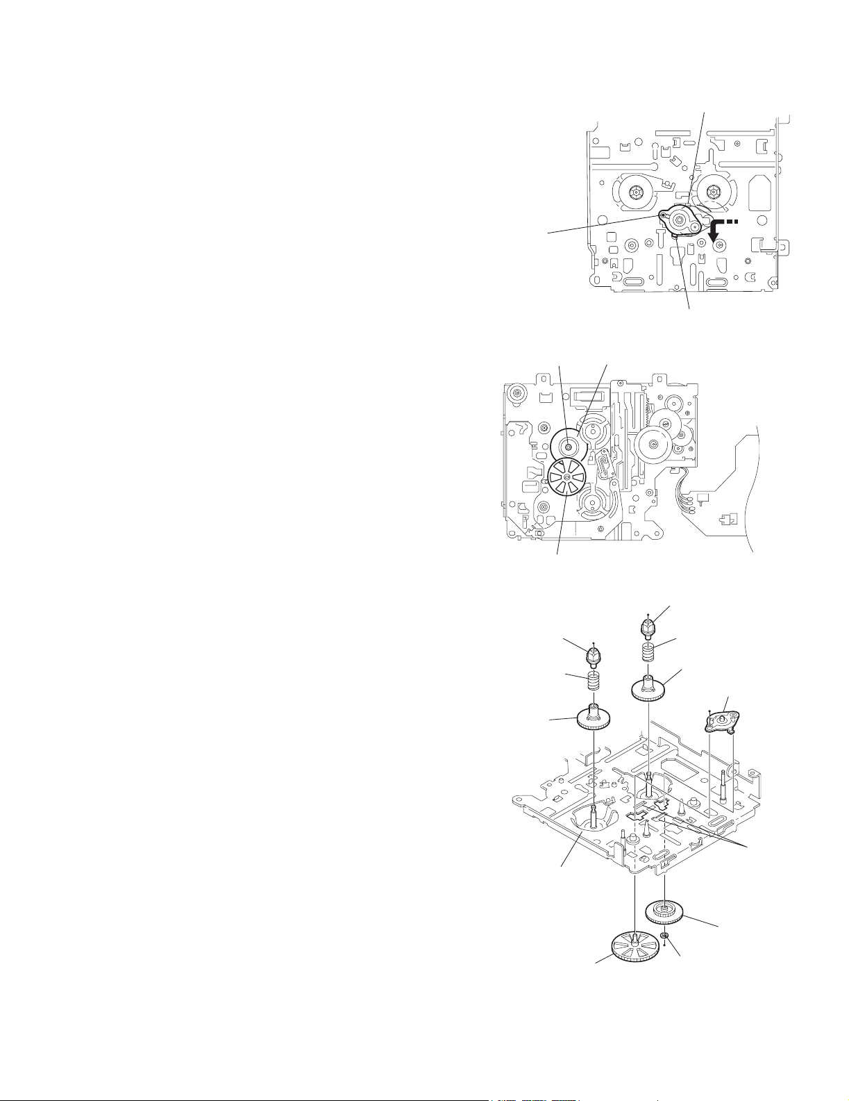
2.2.19 Removing the gear base assembly / take up gear / reflector gear
r
(See Fig.30 to 32)
(1) Push in the pin d’ of the gear base assembly on the upper
side of the body and move the reflector gear toward the
bottom, then pull out.
(2) Remove the polywasher on the bottom and pull out the
take up gear.
(3) Move the gear base assembly in the direction of the arrow
to release it from the two slots e’ of the main chassis.
REFERENCE:
The parts are damaged when removed. Please replace
with new ones.
2.2.20 Removing the reel driver / reel spindle
(See Fig.32)
(1) Draw out the reel driver from the shaft on the main chassis
and remove the reel driver spring and the reel spindle respectively.
CAUTION:
The reel driver is damaged when removed. Please replace with a new one.
Gear base assembly
Pin d'
Polywasher
KS-F545
Slot e'
Slot e'
Fig.30
Take up gear
Reflector gear
Reel driver
Reel driver spring
Reel spindle
Main chassis
Reflector gear
Fig.31
Reel driver
Reel driver spring
Reel spindle
Gear base assembly
Slots e’
Take up gea
Polywasher
Fig.32
(No.49828)1-15
Page 16
KS-F545
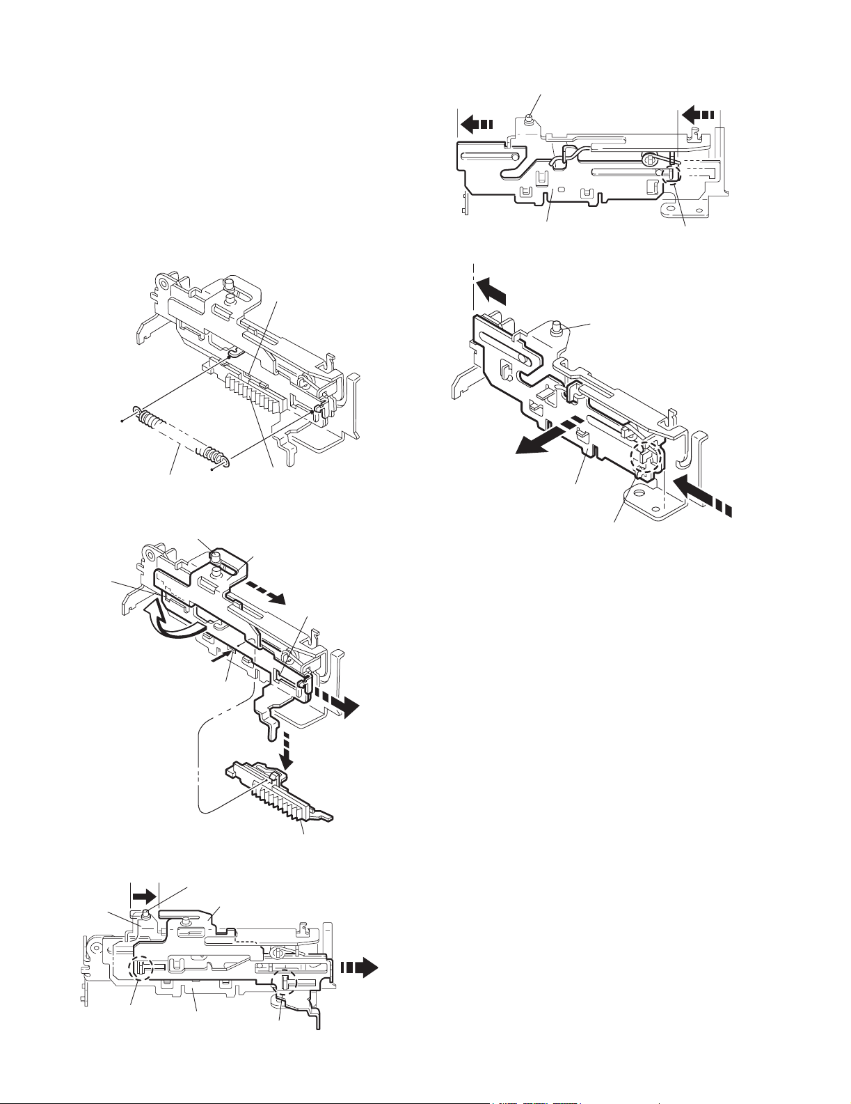
2.2.21 Removing the side bracket assembly
(See Fig.33 to 37)
(1) Remove the eject cam plate spring.
(2) Push the joint f’ through the slot to remove the load rack
downward.
(3) Move the eject cam limiter in the direction of the arrow to
release it from the boss g’ of the side bracket assembly and
from the two joints h’.
(4) Move the eject cam plate in the direction of the arrow to re-
lease the joint i’.
CAUTION:
When reassembling, confirm operation of each part before reattaching the eject cam plate spring.
Joint f'
Side bracket assembly
Boss g'
Eject cam plate
Fig.36
Side bracket assembly
Joint i'
Eject cam plate spring
Side bracket assembly
Joint h'
Side bracket
assembly
Boss g'
Boss g'
Load rack
Fig.33
Eject cam limiter
Joint f'
Fig.34
Eject cam limiter
Eject cam plate
Joint i'
Fig.37
Joint h'
Load rack
Joint h'
1-16 (No.49828)
Eject cam plate
Fig.35
Joint h'
Page 17
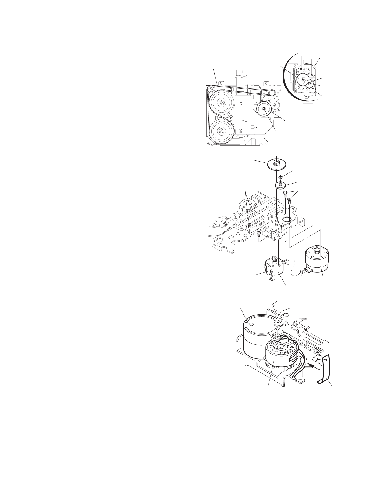
2.2.22 Removing the main motor assembly / sub motor assembly
r
r
r
(See Fig.38 to 40)
(1) Remove the belt at the bottom.
(2) Remove the polywasher and pull out the mode gear.
(3) Pull out the reduction gear (B).
(4) Remove the polywasher and pull out the reduction gear
(A).
(5) Remove the two screws attaching the main motor assem-
bly.
(6) Remove the two screws E attaching the sub motor assem-
bly.
(7) Unsolder the wires on the reel board if necessary.
CAUTION:
When reassembling, adjust the length of the wires extending from the sub motor asswmbly by attaching them
to the side of the sub motor assembly with the wires extending from the main motor assembly using a spacer.
Belt
Reduction gear (B)
Reduction gear (B)
E
Mode gear
Polywasher
Fig.38
Main motor
D
assembly
Reduction
gear (A)
Polywashe
Sub moto
assembly
E
Polywasher
Reduction gear (A)
D
KS-F545
Spacer
Main motor assembly
Sub motor assembly
Fig.39
Main motor assembly
Sub motor assembly
Fig.40
Space
(No.49828)1-17
Page 18
KS-F545
3.1 Adjustment method
Test instruments required for adjustment Standard volume position
1. Digital oscilloscope (100MHz)
2. Frequency counter meter
3. Electric voltmeter
4. Wow & flutter meter
5. Test tapes
VT724.......................for DOLBY level measurement
VT739............For playback frequency measurement
VT712....For wow flutter & tape speed measurement
VT703.....................For head azimuth measurement
6. Torque gauge...................Cassette type for CTG-N
(Mechanism adjustment)
Measuring conditions (Amplifier section)
SECTION 3
Adjustment
Balance and Bass, Treble volume, Fader
: Center (Indication "0")
Loudness, Dolby NR, Sound, Cruise : Off
Volume position is about 2V at speaker output with
following conditions, Playback the test tape VT721.
AM mode 999kHz/62dB, INT/400Hz, 30%
modulation signal on receiving.
FM mono mode 97.9MHz/66dB, INT/400Hz, 22.5kHz
deviation pilot off mono
FM stereo mode 1kHz, 67.5kHz dev. pilot 7.5kHz dev.
Output level 0dB (1 V,50 /open terminal)
Power supply voltage.............. DC14.4V (11V to 16V allowance)
Load impedance............ 4 (4 to 8 allowance)
Line out level/Impedance..............1.0V/20k load (250 nWb/m)
Frequency band
87.5 MHz to 108.0 MHz
65.00 MHz to 74.00 MHz
522 kHz to 1620 kHz
144 kHz to 279 kHz
Band
FM1/FM2
FM3
AM (MW)
AM (LW)
1-18 (No.49828)
Page 19
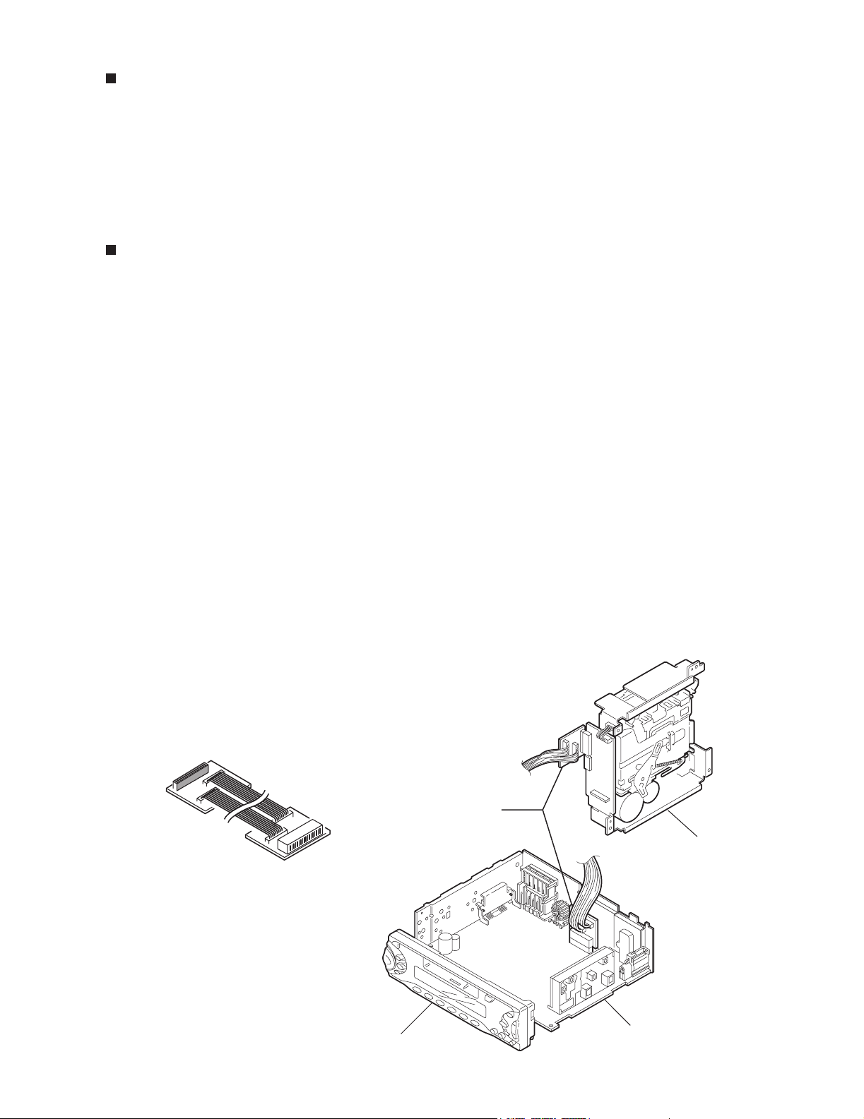
Information for using a car audio service jig
1. We're advancing efforts to make our extension cords common for all car audio products.
Please use this type of extension cord as follows.
2. As a U-shape type top cover is employed, this type of extension cord is needed to check operation of the
mechanism assembly after disassembly.
3. Extension cord : EXTKSRT002-18P ( 18 pin extension cord ) For connection between mechanism assembly
and main board.
4. Check for mechanism driving section such as motor ,etc.
Disassembly method
1. Remove the front panel assembly.
2. Remove the bottom cover.
3. Remove the front chassis.
4. Remove the heat sink.
5. Remove the rear panel
6. Remove the main board.
7. Reattach the heat sink with the two screws B. (Refer to Disassembly method.)
8. Reattach the rear panel with the screw E. (Refer to Disassembly method.)
9. Reattach the front panel assembly.
10. Confirm that current is being carried by connecting an extension cord jig.
Note
Available to connect to the CJ601 connector when installing the front panel.
KS-F545
CAUTION :
Be sure to attach the heat sink and rear panel on the power amplifier IC and regulator IC
of a main board when supplying the power.
If voltage is applied without attaching those parts, the power amplifier IC and regulator IC
will be destroyed by heat.
To
Cassette mechanism
Extension cord
EXTKSRT002-18P
To
Main board
Cassette mechanism
EXTKSRT002-18P
Front panel assembly
Main board
(No.49828)1-19
Page 20
KS-F545
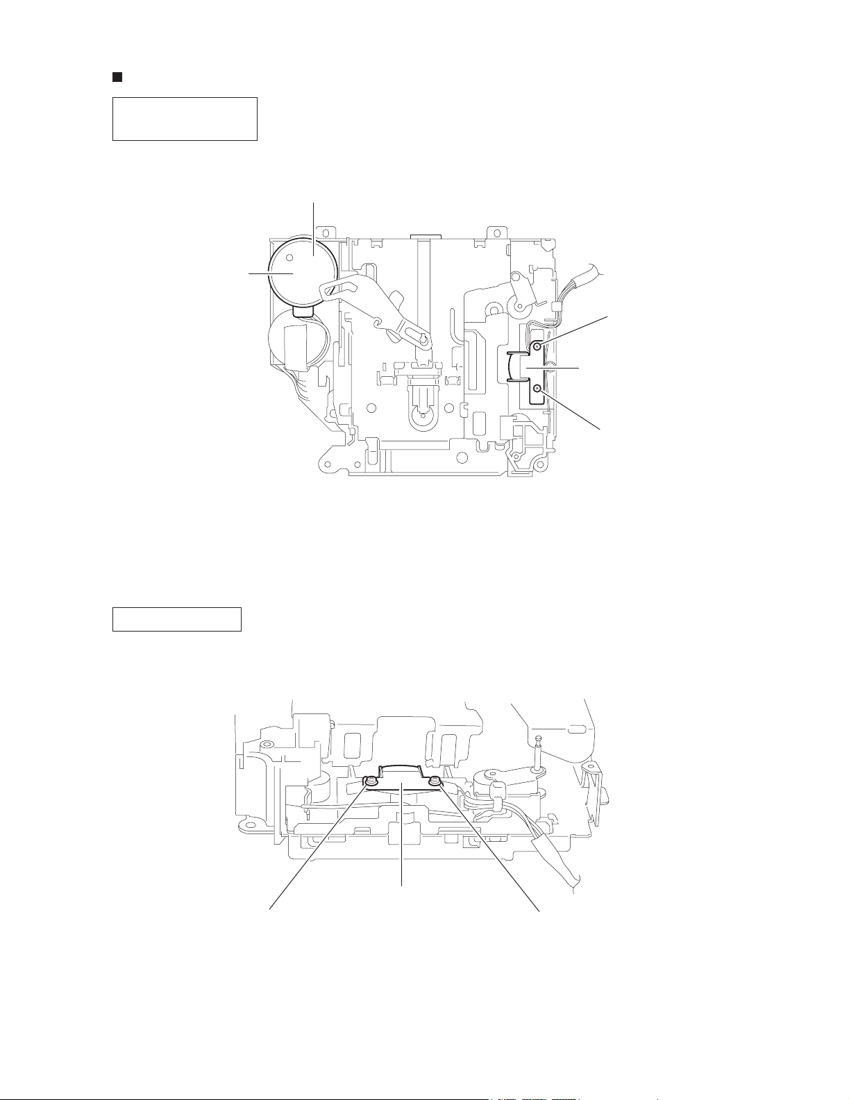
A
Arrangement of adjusting & test points
Cassette mechanism
(Surface)
Motor assembly
Tape speed adjust
Azimuth screw
(Forward)
Playback head
Head section view
Azimuth screw B
(Reverse)
1-20 (No.49828)
Azimuth screw B
(Reverse)
Playback head
Azimuth screw A
(Forward)
Page 21
KS-F545
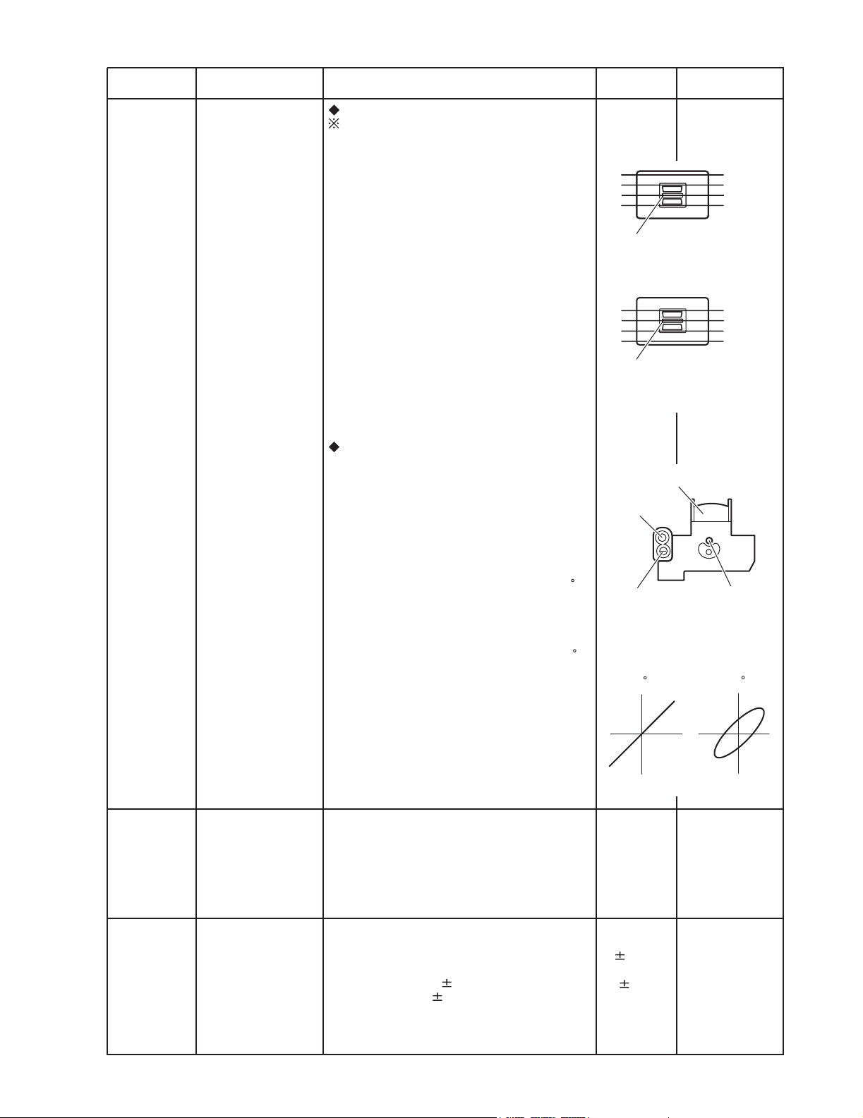
Item
Head
1.
azimuth
adjustment
Conditions
Test tape:
SCC-1659
VT703 (10kHz)
Test tape:
VT724 (1kHz)
VT703 (10kHz)
VT721 (315Hz)
Adjustment and Confirmation methods
Head height adjustment
Adjust the azimuth directly. When you
adjust the height using a mirror tape,
remove the cassette housing from the
mechanism chassis. After installing the
cassette housing, perform the azimuth
adjustment.
Load the SCC-1659 mirror tape. Adjust with
1.
height adjustment screw A and azimuth
adjustment screw B so that line A of the
mirror tape runs in the center between Lch
and Rch in the reverse play mode.
After switching from REV to FWD then to
2.
REV, check that the head position set in
procedure 1 is not changed. (If the position
has shifted, adjust again and check.)
Adjust with azimuth adjustment screw B so
3.
that line B of the mirror tape runs in the
center between Lch and Rch in the forward
play mode.
Head azimuth adjustment
Load VT724 (1kHz) and play it back in
1.
the reverse play mode.
Set the Rch output level to max.
Load VT703 (10kHz) and play it back in
2.
the forward play mode. Adjust the Rch
and Lch output levels to max, with
azimuth adjustment screw B. In this case,
the phase difference should be within 45 .
Engage the reverse mode and adjust the
3.
output level to max, with azimuth
adjustment screw C.
(The phase difference should be 45 or
more.)
When switching between forward and
4.
reverse modes, the difference between
channels should be within 3dB. (Between
FWD L and R, REV L and R.)
S.Values Adjust
A line
Head shield
The head is at low position
during.
B line
Head shield
The head is at High position
during REV.
Output
level:
Maximum
PBHead
FWD Adj B
REV Adj C
(0 ) (45 )
HEIGHT Adj A
phase
Tape speed
2.
and wow
flutter
confirmation
Play back
3.
frequency
response
confirmation
When VT721 (315Hz) is played back,
5.
the level difference between channels
should be within 1.5dB.
Test tape: VT712
(3kHz)
Test tape: VT724
(1kHz)
VT739
(63Hz / 1kHz / 10kHz)
The tuner section is of an adjustment-freedesign. In case the tuner is in trouble, replace the tuner pack.
Check to see if the reading of the F, counter /
1.
wow flutter meter is within 3015Hz to 3045Hz
(FWD/ REV), and less than 0.35% (JIS RMS).
In case of out of specification, adjust the
2.
motor with a built-in volume resistor.
Play test tape VT724, and set the volume
1.
position at 2V.
Play test tape VT739 and confirm.
2.
1kHz / 10kHz: -1 3dB,
1kHz / 63Hz: 0 3dB,
When 10kHz is out of specification, it will be
3.
necessary to read adjust the azimuth.
Tape speed:
3015Hz
to 3045Hz
Wow
flutter: less
than 0.35%
Speaker out
1kHz / 63Hz
: 0 3dB
1kHz / 10kHz
: -1 3dB
Built-in volume
resistor
(No.49828)1-21
Page 22
KS-F545
SECTION 4
Description of major ICs
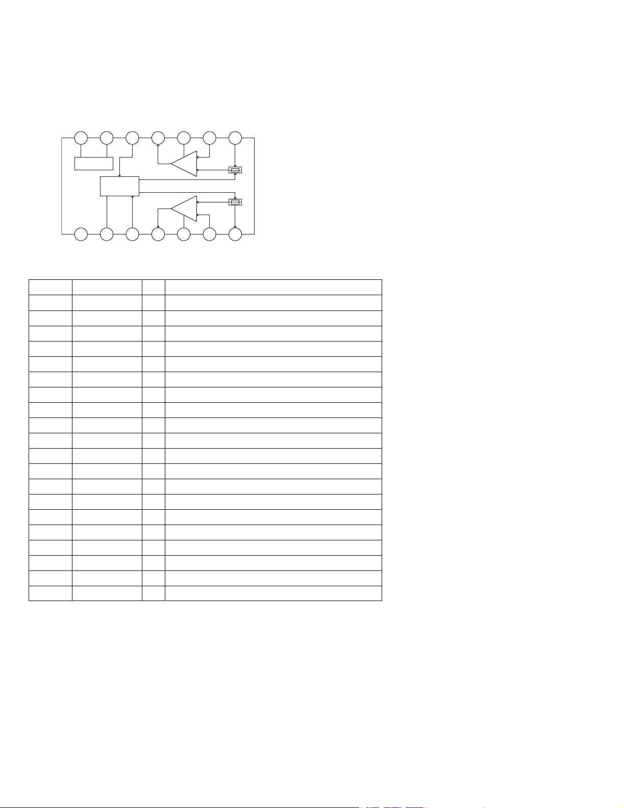
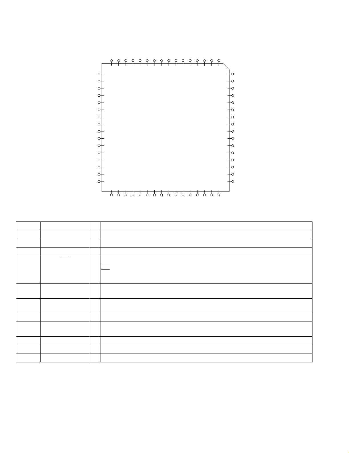
4.1 HA12231FP-X (IC401) : PB Equalizer/Line Mute/Music Sensor
• Pin layout & Block diagram
Vcc
14 13 12 11 10
8
9
Ripple Filter
ALC
1 2 3 4 5 6
GND
Amp.
Ch2
Amp.
Ch1
7
• Pin function
Pin No. Symbol I/O Function
1 VREF O Reference output
2 FIN(R) I Equalizer input
3 RIN(R) I Equalizer input
4 EQOUT(R) O Equalizer output
5 TAI(R) I Tape input
6 PBOUT(R) O PB output
7 MS GV - MS gain terminal
8 120/70 I Mode control input
9 Mute I Mode control input
10 FOR/REV I Mode control input
11 Vcc - Power supply
12 MS O MS output (to MPU)
13 MSDET - Time constant pin for MS rectifier
14 RIP - Ripple filter
15 PBOUT(L) O PB output
16 TAI(L) I Tape input
17 EQOUT(L) O Equalizer output
18 RIN(L) I Equalizer input
19 FIN(L) I Equalizer input
20 GND - Ground
1-22 (No.49828)
Page 23
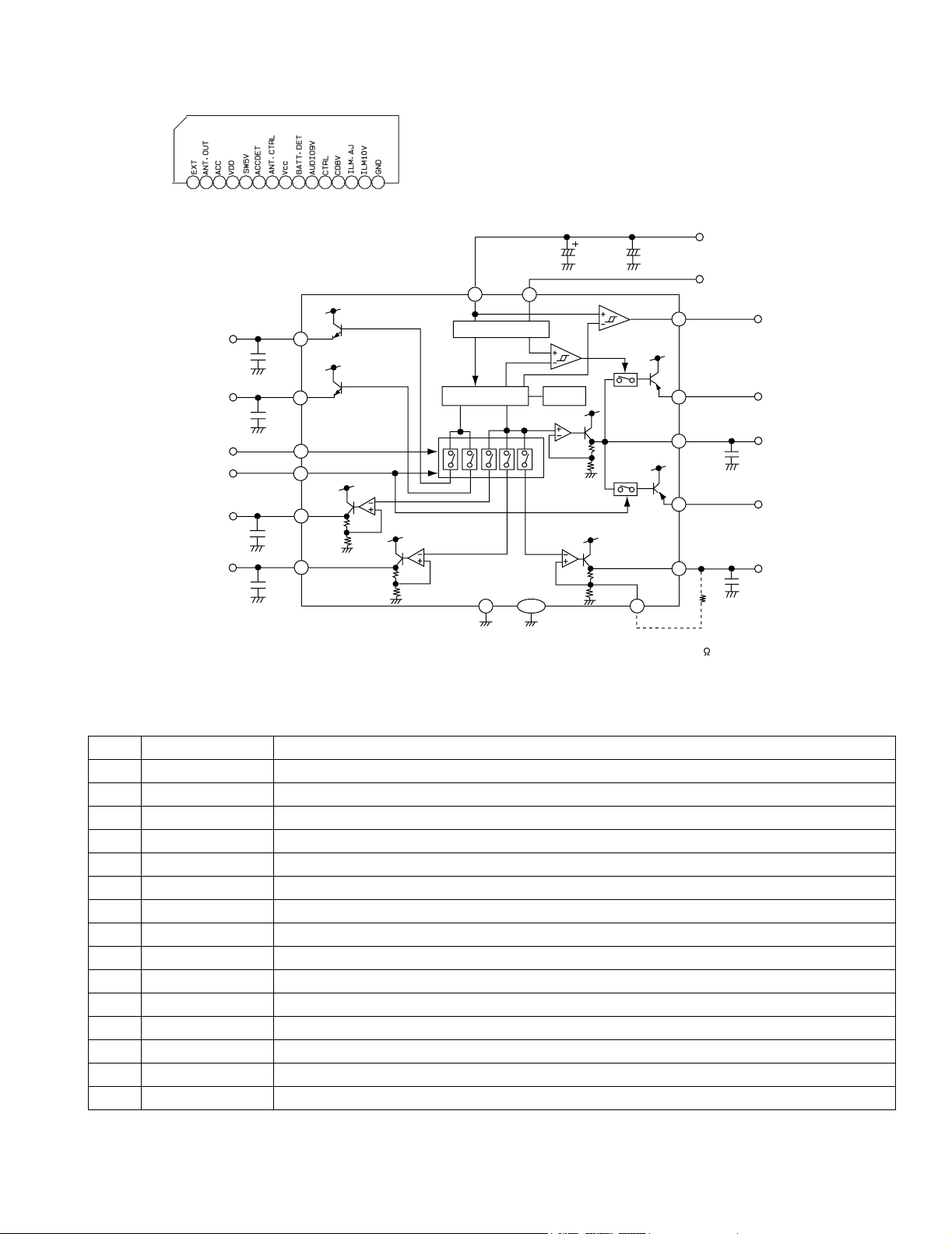
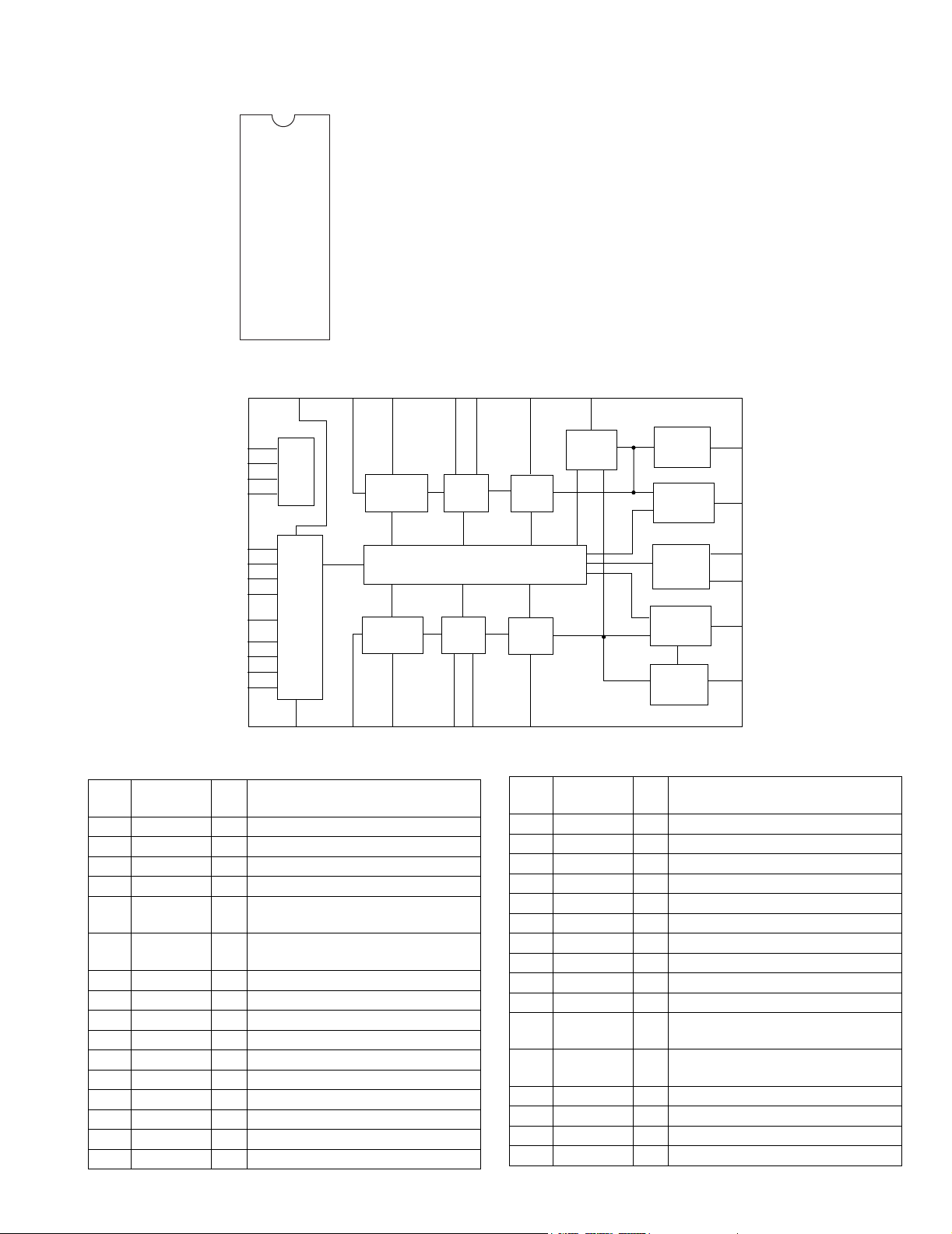
4.2 HA13164A (IC901) : Regulator
• Terminal layout
123456789101112131415
• Block diagram
ANT OUT
EXT OUT
ANT CTRL
CTRL
CD OUT
AUDIO OUT
C3
0.1u
C4
0.1u
C5
0.1u
C6
10u
2
1
7
11
12
10
VCC ACC
8
Surge Protector
BIAS TSD
15
3
TAB
C1
100u
KS-F545
C2
0.1u
13
ILM AJGND GND
+B
ACC
BATT.DET OUT
9
COMPOUT
6
VDD OUT
4
SW5VOUT
5
ILMOUT
14
R1
C7
0.1u
0.1u
C8
UNIT R:
C:F
note1) TAB (header of IC)
connected to GND
• Pin function
Pin No. Symbol Function
1 EXTOUT Output voltage is VCC-1 V when M or H level applied to CTRL pin.
2 ANTOUT Output voltage is VCC-1 V when M or H level to CTRL pin and H level to ANT-CTRL.
3 ACCIN Connected to ACC.
4 VDDOUT Regular 5.7V.
5 SW5VOUT Output voltage is 5V when M or H level applied to CTRL pin.
6 COMPOUT Output for ACC detector.
7 ANT CTRL L:ANT output OFF H:ANT output ON
8 VCC Connected to VCC.
9 BATT DET Low battery detect.
10 AUDIO OUT Output voltage is 9V when M or H level applied to CTRL pin.
11 CTRL L:BIAS OFF M:BIAS ON H:CD ON
12 CD OUT Output voltage is 8V when H level applied to CTRL pin.
13 ILM AJ Adjustment pin for ILM output voltage.
14 ILM OUT Output voltage is 10V when M or H level applied to CTRL pin.
15 GND Connected to GND.
(No.49828)1-23
Page 24
KS-F545
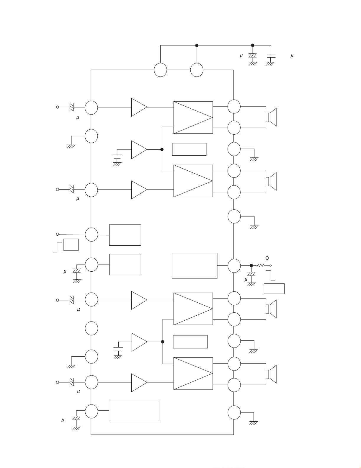
4.3 LA4743K (IC301) : Power amp.
• Block diagram
IN 1
TAB
IN 2
+
0.22 F
+
0.22 F
11
1
12
Vcc 1/2 Vcc 3/4
6 20
-
+
Protective
circuit
-
+
2200 F 0.022 F
+
9
7
+
OUT 1+
OUT 1-
PWR GND1
8
+
OUT 2+
5
-
OUT 2-
3
PWR GND2
2
ST BY
R.F
47 F
IN 3
PRE GND
IN 4
+5V
ST ON
+
0.22 F
N.C
+
0.22 F
4
Stand by
Switch
Mute
10
+
Ripple
Filter
Mute
22
circuit
3.3 F
+
15
-
+
-
17
19
10K
+
OUT 3+
OUT 3-
Low Level
Mute ON
25
18
21
23
PWR GND3
OUT 4+
OUT 4-
13
14
Protective
circuit
-
+
+
-
ON TIME C
1-24 (No.49828)
22 F
Muting &
16
+
ON Time Control
Circuit
PWR GND4
24
Page 25
•Pin layout
TAB
GND
FR-
STDBY
FR+
VP1
RR-
GND
RR+
RIPPLE
INRF
INRR
SGND
FLIN
RLIN
DNTIME
RL+
GND
RL-
VP3
FL+
MUTE
FL-
GND
NC
• Pin function
Pin No. Symbol Function Pin No. Symbol Function
1 TAB Header of IC 14 FLIN Front Lch input
2 GND Power GND 15 RLIN Rear Lch input
3 FR- Outpur(-) for front Rch 16 ONTIME Power on time control
4 STDBY Stand by input 17 RL+ Output (+) for rear Lch
5 FR+ Output (+) for front Rch 18 GND Power GND
6 VP1 Power input 19 RL- Output (-) for rear Lch
7 RR- Output (-) for rear Rch 20 VP3 Power input
8 GND Power GND 21 FL+ Output (+) for front
9 RR+ Output (+) for rear Rch 22 MUTE Muting control input
10 RIPPLE Ripple filter 23 FL- Output (-) for front
11 RRIN Rear Rch input 24 GND Power GND
12 FRIN Front Rch input 25 NC Non connection
13 SGND Signal GND
KS-F545
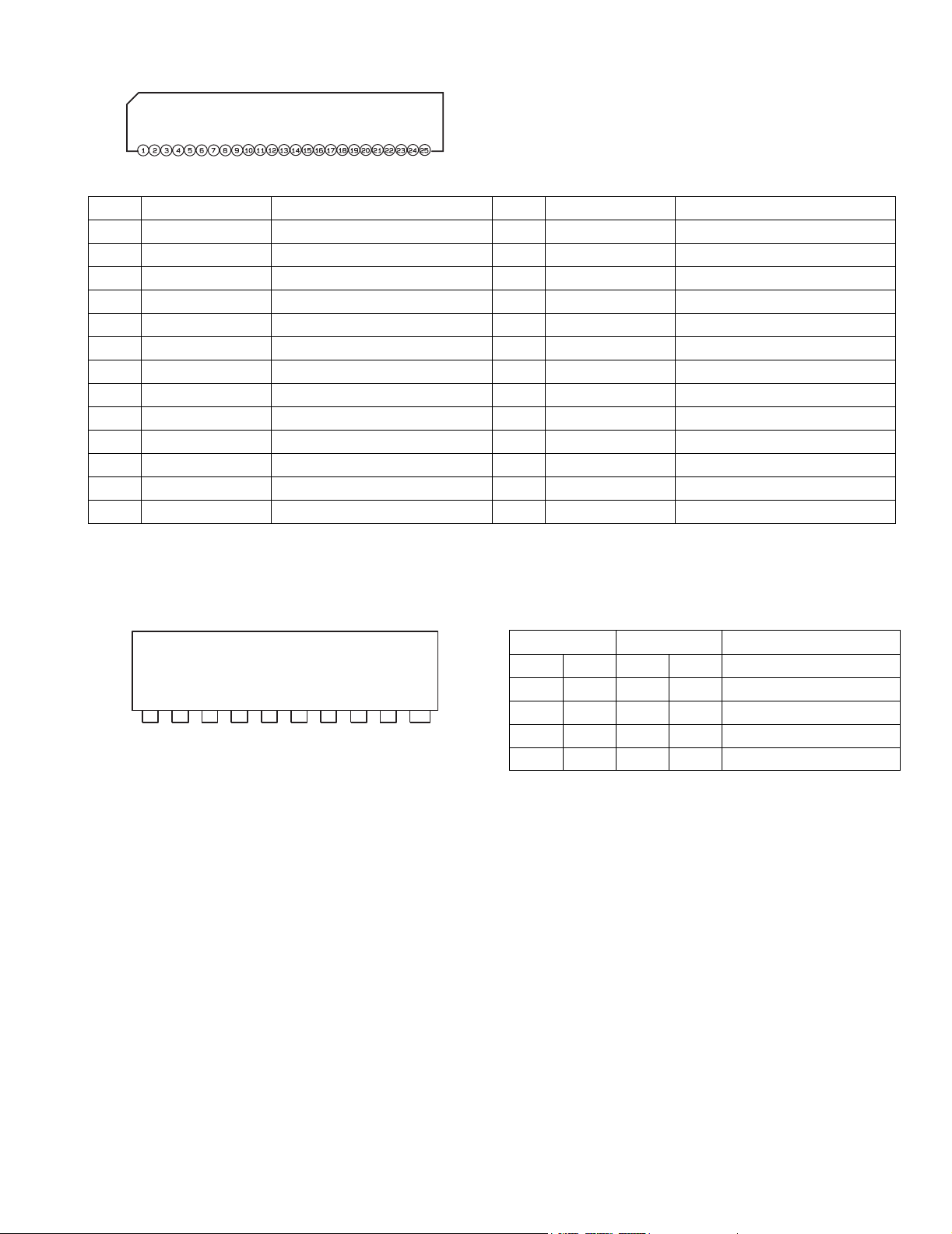
4.4 LB1641 (IC402) : DC Motor driver
•Pin layout •Truth table
Input Output Mode
IN1 IN2 OUT1 OUT2
0000 Brake
1 2 3 4 5 6 7 8 9
GND OUT1 P1
VZ IN1 IN2
VCC1
VCC2 P2
10
OUT2
1 0 1 0 CLOCKWISE
0 1 0 1 COUNTER-CLOCKWISE
1100 Brake
(No.49828)1-25
Page 26
KS-F545
4.5 LC75823W (IC651) : LCD driver
• Pin Layout
DICLCE
OSC
Vss
VDD2
VDD1
INH
VDD
COM3
COM2
COM1
S52
S51
S50
S49
64 63 62 61 60 59 58 57 56 55 54 53 52 51 50 49
1
S1
S2
S3
S4
S5
S6
S7
S8
S9
S10
S11
S12
S13
S14
S15
S16
2
3
4
5
6
7
8
9
10
11
12
13
14
15
16
48
47
46
45
44
43
42
41
40
39
38
37
36
35
34
33
S48
S47
S46
S45
S44
S43
S42
S41
S40
S39
S38
S37
S36
S35
S34
S33
17 18 19 20 21 22 23 24 25 26 27 28 29 30 31 32
S17
S18
S19
S20
S21
S22
S23
S24
S25
S26
S27
S28
S29
S30
S31
S32
• Pin function
Pin No. Symbol I/O Functions
1 to 52 S1 to S52 O Segment output pins used to display data transferred by serial data input.
53 to 55 COM1 to COM3 O Common driver output pins. The frame frequency is given by : t0=(fosc/384)Hz.
56 VDD -- Power supply connection. Provide a voltage of between 4.5 and 6.0V.
57 INH
58 VDD1 I Used for applying the LCD drive 2/3 bias voltage externally.
59 VDD2 I Used for applying the LCD drive 1/3 bias voltage externally.
60 Vss -- Power supply connection. Connect to GND.
61 OSC I/O Oscillator connection.
62 CE I Serial data interface connection to the controller. CE : Chip enable
63 CL I Serial data interface connection to the controller. CL : Sync clock
64 DI I Serial data interface connection to the controller. DI : Transfer data
I Display turning off input pin.
INT="L" (Vss) ----- off (S1 to S52, COM1 to COM3="L"
="H" (VDD)----- on
INT
Serial data can be transferred in display off mode.
Must be connected to VDD2 when a 1/2 bias drive scheme is used.
Must be connected to VDD1 when a 1/2 bias drive scheme is used.
An oscillator circuit is formed by connecting an external resistor and capacitor at this pin.
1-26 (No.49828)
Page 27
4.6 TEA6320T-X (IC161) : E.volume
•Pin layout
SDA
1
GND
2
OUTLR
3
OUTLF
4
TL
5
B2L
6
B1L
7
IVL
8
ILL
9
QSL
10
IDL
11
MUTE
12
ICL
13
IBL
IAL
14
15
16
CD-CH
TAPE
TUNER
IMD
• Block diagram
10 8 9 7 6
32
31
30
29
28
27
26
25
24
23
22
21
20
19
18
17
SCL
VCC
OUTRR
OUTRF
TR
B2R
B1R
IVR
ILR
QSR
IDR
Vref
ICR
CAP
IBR
IAR
KS-F545
5
12
21
31
2
19
POWER
SUPPLY
VOLUME 1
+20 to -31 dB
LOUDNESS
LEFT
16
15
13
11
14
22
20
SOURCE
SELECTOR
VOLUME 1
+20 to -31 dB
LOUDNESS
RIGHT
18
17
23 25 24 26 27 28
• Pin functions
Pin
No.
Symbol I/O Functions
1 SDA I/O Serial data input/output.
2 GND - Ground.
3 OUTLR O output left rear.
4 OUTLF O output left front.
5 TL I Treble control capacitor left channel
or input from an external equalizer.
6 B2L - Bass control capacitor left channel or
output to an external equalizer.
7 B1L - Bass control capacitor left channel.
8 IVL I Input volume 1. left control part.
9 ILL I Input loudness. left control part.
10 QSL O Output source selector. left channel.
11 IDL - Not used
12 MUTE - Not used
13 ICL I Input C left source.
14 IMO - Not used
15 IBL I Input B left source.
16 IAL I Input A left source.
BASS
LEFT
+15 dB
LOGIC
BASS
RIGHT
+15 dB
VOLUME 2
0 to 55 dB
BALANCE
FENDER REAR
VOLUME 2
0 to 55 dB
BALANCE
FENDER FRONT
HC BUS
REC
3
4
32
TREBLE
LEFT
+12 dB
MUTE
FUNCTION
ZERO CROSS
DETECTOR
1
VOLUME 2
TREBLE
RIGHT
+12 dB
Pin
No.
Symbol I/O Functions
0 to -55dB
BALANCE
FENDER FRONT
VOLUME 2
0 to -55dB
BALANCE
FENDER REAR
29
30
17 IAR I Input A right source.
18 IBR I Input B right source.
19 CAP - Electronic filtering for supply.
20 ICR I Input C right source.
21 Vref - Reference voltage (0.5Vcc)
22 IDR - Not used
23 QSR O Output source selector right channel.
24 ILR I Input loudness right channel.
25 IVR I Input volume 1. right control part.
26 B1R - Bass control capacitor right channel
27 B2R O Bass control capacitor right channel
or output to an external equalizer.
28 TR I Treble control capacitor right channel
or input from an external equalizer.
29 OUTRF O Output right front.
30 OUTRR O Output right rear.
31 Vcc - Supply voltage.
32 SCL I Serial clock input.
(No.49828)1-27
Page 28

KS-F545
4.7 UPD178078GF-597 (IC701) : CPU
• Pin layout
~
80
51
100 ~ 81
1
~
30
31 ~ 50
• Pin function
Pin No. Symbol I/O Descriptions
1 ACCDET I Power save 1, working together ACC
2 POWER I Power save 2 , working together Backup
3 PCNT I Power ON/OFF switching output
4 STANDBY I Standby position detection input
5 TAPEIN - Cassette in detection input
6NC-No use
7 BUSI/O - No use
8 BUSSI - No use
9 BUSSO - No use
10 BUSSCK - No use
11 I2CDAI - No use
12 I2CDAO O I2C information data output
13 I2CSCK O I2C information clock output
14 MODE I/O Mechanism mode position detection input
15 SUBMO+ I Sub motor positive direction input
16 SUBMO- O Sub motor negative direction output
17 REEL O Switch for detecting tape end position
18 MSIN I MS input
19 DOLBY O Dolby on "H" output
20 F/R O FWD/REVERSE running direction switch signal input
21 FF/REW I Output for input signal level switching for MS
22 MOTOR O Main motor output
23 LEVEL I Level meter input
24 SM I S.meter level input
25 SQ I Q.quality level input
26 NC - No use
27 AVDD - VDD
28 NC - No use
29 KEY0 I Key input 0
30 KEY1 I Key input 1
31 KEY2 I Key input 2
32 AVSS - GND
33 REGCPU - Regulator for CPU
34 VDD - VDD
35 REGOSC - Regulator for OSC
36 X2 - Connecting the X'tal oscillator for system clock
37 X1 I Connecting the X'tal oscillator for system clock
38 GND0 - GND
39 SEEK/STOP O Auto seek / Stop selecting output
1-28 (No.49828)
Page 29

Pin No. Symbol I/O Descriptions
40 GND2 - GND
41 NC - No use
42 IFC I FM/AM middle frequency counter input
43 VDDPLL - VDD for PLL
44 FMOSC I FM/AM limited generator frequency counter input
45 NC - No use
46 GNDPLL - PLL for GND
47 AME0 O AM error out output
48 FME0 O FM error out output
49 VPP - VPP
50 RESET - Pull up
51 RDSSCK - No use
52 RDSDA - No use
53 MONO O Monoral ON/OFF selecting output
54 SD/ST I Station detector, Stereo signal input
55 FM/AM O FM/AM switching output
56 AFCK - No use
57 DETACH I Detach signal input
58,59 NC - No use
60 LCDDA O Data output for LCD driver
61 LCDSCK O Serial clock ooutput for LCD driver
62 LCDCE O Chip enable output for LCD driver
63~68 NC - No use
69 RX - No use
70 TX - No use
71 IFC CONT I IFC control signal input
72 OPEN I Door open detect signal input
73~77 NC - No use
78 REMOCON I Remocon signal input
79 NC - No use
80 J-BUSINT - No use
81 (STERING) - No use
82 GND1 - GND
83 STAGE1 I No use
84 STAGE2 I No use
85 MUTE O Mute output
86,87 NC - No use
88 TELMUTE I Telephone mute signal detection input
89 NC - No use
90 (DIMMER OUT) - GND
91 (ENC1) O No use
92 (ENC2) O No use
93 (DIMMER IN) - No use
94 ANT I Remote antenna detection input
95~98 NC - No use
99 VDDPORT - VDD
100 GNDPORT - GND
KS-F545
(No.49828)1-29
Page 30

KS-F545
VICTOR COMPANY OF JAPAN, LIMITED
AV & MULTIMEDIA COMPANY MOBILE ENTERTAINMENT CATEGORY 10-1,1chome,Ohwatari-machi,Maebashi-city,371-8543,Japan
(No.49828)
Printed in Japan
20034WPC
Page 31

SCHEMATIC DIAGRAMS
CASSETTE RECEIVER
KS-F545
CD-ROM No.SML200304
Area Suffix
KS-F545
Contents
Block diagram
Standard schematic diagrams
Printed circuit boards
EE --------- Russian Federation
MO
RPT
2-1
2-2
2-5 to 7
SCM
MODE
COPYRIGHT 2003 VICTOR COMPANY OF JAPAN, LTD.
No.49828SCH
2003/04
Page 32

KS-F545
Safety precaution
!
Burrs formed during molding may be left over on some parts of the chassis. Therefore,
pay attention to such burrs in the case of preforming repair of this system.
2-4
Page 33

Block diagram
5
TAPE IN SW
STAND BY SW
MODE SW
KS-F545
SUB
MOTOR
MAIN
MOTOR
HEAD
CN403
4
3
2
J1
AM
FM
TO
SPEAKER
CONNECTOR
CP901
FLOUT+,FLOUTFROUT+,FROUTRLOUT+,RLOUTRROUT+,RROUT-
IC301
POWER AMP.
FL,FR
RL,RR
IC161
E.VOLME
TU.L
TU.R
TU1
AM/FM TUNER
TO
REAR LINE OUT
SEEK/STOP
SD/ST,SK/ST
SM,FMEO
AMEO,FM/AM
MONO,FMOSC
RL
RR
J321
TAPE.L
TAPE.R
IC701
CPU
F/R
MODE
STANDBY
FF/REW
MOTOR
SUBMO+
SUBMOTAPEIN
DOLBY
MS
REEL
LCDDA
LCDCK
LCDCE
CN401
CP401
MOTOR
TAPEIN
MODE
STANDBY
REEL
F/R
MSOUT
Lch
Rch
FF/REW
SUBMO+
SUBMO-
LCDDA
LCDCK
LCDCE
CN402
FWD-L
FWD-R
REW-L
REW-R
SUBMO+
SUBMO-
IC401
PB EQ
IC402
DC MOTOR DRIVER
Head amp section
LCD1
S3 to S52
COM1 to COM3
IC651
LCD DRIVER
KEY
S601 to S606
CJ601
KEY0 to KEY2
Main amp section
CP701
KEY0 to KEY2
S608 to S621
LCD & Key control section
1
AB CD E F G
2-1
Page 34

Standard schematic diagrams
Main amp section
TU1
C32
0.22
Q32
Q701
2SC2412K/R/-X
D705
UDZS6.2B-X
10V
R706
R701
R702
R703
D707
D706
UDZS6.2B-X
UDZS6.2B-X
1k
R31
QAU0293-001
QNB0100-002
2SC2412K/R/-X
2SC2412K/R/-X
TAPEIN
MODE
SUBMO+
SUBMO-
REEL
DOLBY
FF/REW
MOTOR
10k
C710
0.1
J1
R34
R44
10k
MS
F/R
0
0
0
R43
R42
1k
Q41
REMOCON
C41
0.001
DETACH
ACC5V
LCDCE
LCDCK
LCDDA
ENC1
ENC2
C717
0.047
L1
4.7u
D5
D6
1SS355-X
1SS355-X
C33
C43
150P
0.47/50
1k
1k
C34
C42
2.2/50
Q42
SW5V
KEY0
KEY1
KEY2
0.1
C1
100/16
33
10V
2SA1037AK/RS/-X
4.7k 47k
R2
Q1
UN2211-X
D1
MTZJ9.1C-T2
C2
Q2
R3
TAPE.L
47K
Q33
UN2211-X
1.5k
R41
R1
FMEO
AMEO
FM/AM
9V
5
R33
1k
R32
1k
C31
2SC3661-X
R748
2SC3661-X
Q31
68k
0.082
4
3
To
Head amp
section
CN401
CP401
QGB1214J1-18S
To
LCD & Key
control
section
CP701
2
CJ601
VMC0334-001
D701
UDZS6.2B-X
D703
D702
UDZS6.2B-X
UDZS6.2B-X
D704
UDZS6.2B-X
1
47p
UN2211-X
KS-F545
1/50
C5
C6
UN2211-X
1/50
0.1/50
47p
Q8
0.015
0.015
C8
C81
C82
2SC2412K/R/-X
Q4
UN2111-X
FMOSC
SM
47k
R740
R754
GND
C718
C704
R12
68
220/10
C9
0.047
2SA1037AK/RS/-X
C3
D7
1SS355-X
R4
3.3k
R14
10k
Q12
TAPE.R
R750
22k
10p
R11
C85
D3
D2
Q9
Q3
47k
R5
1SS355-X
1SS355-X
SEEK/STOP
SM
9V
MONO
REMOCON
LCDCK
LCDDA
LCDCE
DETACH
47u
L2
ENC1
ENC2
KEY0
KEY1
KEY2
ACC5V
R81
10k
R82
10k
C7
4.7k
R8
C84
R162
0
C87
390p
R161
0
100/6.3
SK/ST
47k
R755
R764
4.7k
330p
R59
470
TAPE.R
TAPE.L
ANT
MUTE
TELMUTE
R741
47k
47k
R753
47k
4.7k
R763
47k
R756
VDD
4.7k
R728
R718
10k
R719
10k
R727
4.7k
R720
R58
15k
R726
10k
R722
10k
4.7k
R721
10k
C709
0.1
TU.R
TU.L
R83
15k
0.0012
C83
R84
15k
0.0012
1/50
C164
0
R164
0
R163
C163
1/50
0
R709
10k
TAPEIN
STANDBY
R731
1/50
C165
C162
1/50
C167
47/16
47k
22k
47k
R761
R762
R765
47k
R732
R725
TX
R723
RX
C168
4.7k
R724
4.7k
100/16
IC701
uPD178078GF-597
4.7k
2.2k
R168
22k
R167
0.18
C172
C173
0.0082
C176
0.033
0.22
C174
0.22
C171
C169
0.0082
C175
C170
0.18
22k
R165
R166
2.2k
R169
R170
MONO
FM/AM
47k
R733
R737
47k
R736
47k
R742
56k
47k
R735
47k
R745
R743
47k
R746
47k
R734
47k
47k
R747
R738
47k
0.033
220k
220k
KS-F545
C178
0.0056
C177
C179
0.082
0.0056
D161
1SS355-X
1SS355-X
D162
47k
R711
RESET
R729
47k
VPP
R760
C701
10k
R713
0.1
3.3k
3.3k
R248
220
0.22
D243
C244
UDZS5.1B-X
C180
R759
47k
0.001
SEEK/STOP
QAX0406-002Z
33p
C705
0.1
C708
R757
R758
RB160M-30-X
68k
R247
IC301
LA4743K
22/16
RB160M-30-X
RB160M-30-X
47/16
C302
C327
0.1
4.7/50
C305
C307
0.22
D904
C913
10k
R912
0.1
150P
C306
0.047
C904
2200/16
C903
1N5401-F64
D901
0.047
C902
L901
QQR0703-001
2.2
F1
C910
QMFZ047-150-T
RLOUT+
C911
C901
10/16
47
R901
FLOUT+
FROUT+
RROUT+
C323
0.1
C324
0.1
C325
0.1
C326
0.1
FLOUT-
RLOUT-
FROUT-
RROUT-
ACC
GND
TELMUTE
MEMORY
REMOTE
CP901
QNZ0112-001
QAM0175-002
Parts are safety assurance parts.
When replacing those parts make
sure to use the specified one.
FRONT SIGNAL
REAR SIGNAL
J321
QNN0519-001
R301
27k
RR
RL
R351
R331
R352
R342
100
100
1k
FR
FL
C783
HA13164A
Q902
2SA1855/RST/-T
R891
D353
1SS355-X
R353
2.2k
1SS355-X
R306
R309
47k
47k
0.1
IC901
UN2211-X
47k
R892
D891
C891
Q901
1SS355-X
R333
D333
2.2k
2SD1781K/QR/-X
R782
47k
D902
1SS355-X
47k
R907
1k
R906
R905
10k
220/10
2200/6.3
C909
1k
1SS355-X
D892
0.1
C181
2.2/50
C183
2.2/50
270
R173
IC161
TEA6320T-X
R172
270
C184
2.2/50
C182
2.2/50
10
R171
100/16
9V
Q976
UN2211-X
POWER
100k
R976
SD/ST
ACC5V
ANT
9V
10V
C719
0.01
PCNT
10k
SW5V
R749
FMEO
AMEO
47k
FMOSC
0.1
SK/ST
22p
C707
X701
C706
0.001
C713
PCNT
POWER
R707
4.7k
SCL
SDA
R708
4.7k
LMETER
C243
0.047
D242
Q241
D241
2SD601A/R/-X
1SS355-X
C242
22/16
FL
RL
R307R6R308
SDA
47k1247k
PCNT
SCL
9V
RR
FR
MUTE
LMETERSTANDBY
27k
R977
12k
R978
Q977
2SA1037AK/RS/-X
C702
L902
C703
47u
47u
220/10
L903
X1
TELMUTE
330P
C714
R243
12k
180k
R242
C241
1/50
47
R245
22k
1k
R244
R246
Q891
UN2211-X
47k
R241
1k
1k
R332
Q351
2SD1781K/QR/-X
Q331
2.7k
R781
UN2211-X
Q784
D782
1SS355-X
D783
1SS355-X
0.1/50
18k
4.7k
1/50
C905
R904
C908
R903
C907
C308
0.22
0.22
R302
C309
27k
R311
27k
C318
0.22
0.22
R312
1k
R322
4.7k
1SS355-X
1SS355-X
27k
D343
D323
D781
MTZJ11C-T1
R910
2SD1781K/QR/-X
100/16
C906
C319
R343
2.2k
R323
2.2k
100/16
C781
220/10
C982
10/16
390p
390p
C303
C304
390p
390p
C313
C314
Q781
UN2111-X
UN2111-X
C782
RB160M-30-X
D982
C321
0.01
C322
150p
100
100
1k
4.7/16
C301
R305
R341
R321
Q341
2SD1781K/QR/-X
Q321
D903
10k
R902
R981
R982
RB160M-30-X
D981
C912
100/10
0.1
C981
Q782
TUNER SIGNAL
TAPE SIGNAL
MS
DOLBY
FF/REW
F/R
MODE
SUBMO+
SUBMO-
REEL
MOTOR
2-2
HAB C DE FG
Page 35

KS-F545
LCD & Key control section
5
To
Main amp section
CJ601
VMC0335-001
CP701
KEY2
LCDDA
LCDCK
LCDCE
ACC5V
KEY1
KEY0
REMOCON
10V
4
GND
LCD1
QLD0251-001
S3S4S5S6S7S8S9
S10
S11
S12
S13
S14
S15
S16
S17
S18
S19
S20
S21
S22
S23
S24
S25
S26
S27
S28
S29
S30
S31
S32
S33
S34
S35
S36
S37
S38
S39
S40
S41
S42
S43
S44
S45
S46
S47
S48
S49
S50
S51
S52
COM1
COM2
COM3
S39
S43
S42
S41
S40
S45
S48
S44
S47
S46
S49
S50
S51
S617
S52
COM1
COM2
COM3
INH
OSC
CLOCK
S5
S4
S3
S6
R603
1.2k
S603S602
R609
1.2k
S610
R615
1.2k
S604
S611
S618
3
10k
10k
10k
R655
R656
R654
2
R649
D619
D620
1k
1k
R648
R647
D616
D617
D618
680
R646
D613
R637
D602
D601
D603
2.2k
R636
820
2.2k
R635
D608
D604D605
D606
1.2k
1k
1k
R638
R639
D614
R643
D607 D611
D609 D612
1.2k
R641
390
390
R642
R640
D615
D610
680
390
390
R645
R644
D657
10K
R657
MA3062
2.2k
2.2k
IC652
RPM6938-SV4
R659
R660
C654
4.7/6.3
47
R658
330
R630
D640
NSPW310BS/B2RS/
D655
MA152WK-X
330
R631
D641
NSPW310BS/B2RS/
D654
MA152WK-X
MA152WA-X
D653
R653
S601
S615
S608
180K
MA152WA-X
R613
D652
R607
820
R601
820
820
UDZS5.6B-X
D651
C651
R652
10/6.3
0.022
C653
680p
S616
C652
S609
R661
10k
47k
R602
820
R608
820
R614
820
S38
S37
S35
S36
S8
S7
R616
1.8k 2.7k
S13
S12
S11
S14
S10
S9
R604 R605
1.8k
R610 R612R611
1.8k 3.9k2.7k
S605
S34
S33
S32
S31
S30
S29
S28
S27
S26
S25
S24
S23
S22
S21
S20
S19
S18
S17
S16
S15
2.7k
S612
R617
S619
S613
S620
S606
IC651
LC75823W
R618
3.9k
S614
S621
1
AB CD E F G
2-3
Page 36

Head amp section
KS-F545
KS-F545
5
680
CN403
QGF1219F1-10S
R410
Q403
2SB1322/RS/-T
3.3k
1A3G-T1
D402
R422
47k
R423
Q402
UN2211-x
4
680p
680p
C401
C411
100k
R401
100k
R412
100k
R402
680p
C412
680p
C402
R415
4.7k
R405
4.7k
R414
5.6k
R404
5.6k
C414
0.1
C404
0.1
C406
0.01
R406
47k
C403
0.18
R403
1M
IC401
HA12231FP-X
C416
1/50
R416
2.4k
Q406
UN2211-x
R408
680
C407
2.2/50
R407
10k
C405C408
1/50100/16
IC402
LB1641
C425
10/16
C423
0.01
0.1
C424
33
R425
C417
2.2/50
R417
10k
C415
0.01
D401
MA3047/H/-X
3.3k
R424
100k
R411
3
CN402
QGA2001C1-06
2
CN401
QGB1214K1-18S
To
Main amp section
CP401
TAPE SIGNAL
1
2-4
HAB C DE FG
Page 37

Printed circuit boards
Main board
5
J321
Q341
Q331
R341
R351
Q351
R353
R343
L1
R352
D353
C87
C1
D1
C3
Q31
Q32
Q53
Q52
R56
C53
R12
R713
C52
C86
C55
R33
D2
R3
C2
C9
C8
C85
C43
R82
B7
C6
C5
R60
Q8
C7
R57
Q51
R722
L2
R718
R727
R728
R719
R701
R750
R702
CJ601
D5
D6
4
3
Q33
Q3
C34
D3
R5
R34
C33
B4
Q12
C82
C81
B8
R14
B9
R11
C51
Q9
B10
2
R331
B322
D343
R322
C906
R1
R43
C31
Q41
Q42
C42
R4
D7
R41
Q2
R2
Q1
R6
Q5
R83
B720
B6
R8
Q4
C54
R53
R54
R58
R59
R55
D701
D702
D703
D704
C701
R703
R32
D4
B5
R333
R342
R31
Q321
D333
R332
C32
R84
R81
C321
B2
R321
R323
D323
R42
R44
R711
C83
R726
B321
C41
R9
C84
C322
Q6
C705
R720
D705
Q7
R746
B721
R15
D706
R10
Q10
R734
D707
C802
C706
GND
VDD
R709
KS-F545
C913
B913
C174
R804
R170
B802
R168
C176
B242
D981
R307
C181
C183
C175
R802
R306
C178
C168
C242
C801
R981
R912
C912
C177
R982
C319
R245
C803
R805
C981
D903
R312
C72
R71
R801
D904
C303
R302
R301
R173
C327
C179
R166
R246
C71
R172
C184
C170
R243
C243
IC71
C910
B911
C180
C182
C241
B243
B782
B781
R242
R244
B801
R309
R241
R976
C76
C314
C309
C78
R308
C781
Q781
R171
Q891
R311
D162
Q976
C782
R782
C75
CP901
L902
R891
C318
X71
C324
R977
R892
B171
C307
R73
C302
R978
C903
R305
D781
D892
C783
R72
C308
C73
C326
D783
R781
C77
C74
C313
B792
C909
C891
B891
Q784
L903
C304
Q782
C703
C323
IC301
C301
D782
D891
Q977
C305
C325
C306
C904
C908
B161
C165
C161
C171
C169
R807
B163
R165
R809
R169
D242
D243
C162
R248
B164
Q241
B910
C901
Q902
C167
R803
C704
IC801
D901
B912
R167
R810
L901
R901
B162
C172
D982
C173
D161
C905
C982
R905
B909
C163
B712
R756
B715
R755
RESET
B904
R906
R164
R754
IC701
R740
R741
R725
R729
B806
R161
C164
R765
B905
B713
R731
R903
R761
B805
R902
Q901
R162
IC161
R753
R806
C709
C166
R907
C902
D902
C244
R247
D241
R808
J801
R910
IC901
R742
B706
B714
R737
B705
R717
R715
R716
B710
B701
B704
R749
R736
R748
B703
B711
C718
B901
R759
CP401
Q701
B722
R743
R745
R735
R757
R758
R714
C4
R721
B716
C708
C707
X701
R760
C702
C710
B702
R763
VPP
R733
B709
B707
R738
B719
R724
R747
R723
R762
B903
B906
B907
R707
R163
B708
RX
R706
R764
R904
C907
R708
R732
TX
B718
B717
1
AB C
2-5
Page 38

KS-F545
Front board
5
D601
S605
R605
S608
D618
IC652
D616
S604
R601
R604
D617
LCD1
S606
R607
D613
S609
D614 D615
R608
S601
D619
R603
S603
R602
S602
D620
4
Forward side
S610
R609
S611
D610
R610
S612
D611
S615
D612
R613
R614
R611
D609
S616
S613
D607
S617
R612
C653
R652
D608
D641
D604
S620
D605
S621
D606
R615
R617
R618
R616
S618
S619
S614
D602
D603
3
Reverse side
R642
D654
D653
R655
C652
D655
D652
C651
R656
D640
D641
R631
R654
R661
R643
R630
CP701
IC651
R657
D657
IC652
R635
R645
R644
R658
C654
R646
R648
R649
R647
D651
R638
R639
R660
R659
R653
R637
R636
2
R641
R640
1
2-6
AB CD
Page 39

KS-F545
Mecha board
5
C415
C403
R403
B403
B414
B404
IC401
CN403
C417
R417
B412
B405
R423
R407
C404
C407
CN401
R404
R405
R402
R401
C401
C402
B411
R412
C412
R414 R415
C414
B402
C411
B401
R411
CN402
R422
Q402
C405
C424
B415
D402
Q406
R410
C408
R416
R406
C406
R408
Q403
B413
C416
B406
B416
R425
R424
IC402
C425
C423
4
D401
3
2
1
AB C
2-7
Page 40

KS-F545
VICTOR COMP ANY OF JAP AN, LIMITED
AV & MULTIMEDIA COMPANY 10-1,1Chome,Ohwatari-machi,Maebashi-city,371-8543,Japan
(No.49828SCH)
Printed in Japan
2003/04
Page 41

PARTS LIST
[ KS-F545 ]
* All printed circuit boards and its assemblies are not available as service parts.
Area suffix
KS-F545
EE --------- Russian Federation
- Contents -
Exploded view of general assembly and parts list (Block No.M1)
Cassette mechanism assembly and parts list (Block No.MP)
Electrical parts list (Block No.01~03)
Packing materials and accessories parts list (Block No.M3)
3-2
3-4
3-8
3-12
No. 49828 3-1
Page 42

KS-F545
Exploded view of general assmbly and parts list
Block No.
4515
4553
4554
4552
12
M
4511
M
1
M
A
4515
4557
4551
4555
16
4556
10
Main board
21
14
B
20
18
48
45
50
47
43
46
LCD1
17
14
A
8
Mecha
control board
9
16
24
25
23
19
18
6
2
5
13
42
13
4
7
5
42
41
22
Front board
35
58
30
13
36
5
38
29
28
32
37
40
39
33
49
44
34
3-2
B
3
13
1
5
31
26
27
Page 43

General assembly
Block No. [M][1][M][M]
Symbol No.
1 ------------ MECHA
2 FSYH4036-050 SHEET
3 GE20136-001A MECHA BKT(L)
4 FSKL2002-002 MECHA BKT(R)
5 QYSDST2606Z SCREW 2.6mm x 6mm(x4)
6 QYSDST2606Z SCREW 2.6mm x 6mm
7 LV40847-002A SPACER
8 GE10043-011A TOP CHASIS
9 GE40135-001A EARTH PLATE
10 GE30568-006A HEAT SINK
11 GE30393-001A BOTTOM COVER
12 FSMA3004-203 INSULATOR
13 QYSDST2604Z SCREW 2.6mm x 4mm(x4)
14 FSKZ4005-001 SCREW (x2)
15 QYSDST2604Z SCREW 2.6mm x 4mm(x2)
16 QYSDST2606Z SCREW 2.6mm x 6mm(x2)
17 QYSDST2612Z SCREW 2.6mm x 12mm(x2)
18 QYSDST2004M MINI SCREW 2mm x 4mm(x2)
19 GE10054-001A FRONT CHASSIS
20 GE30583-001A LOCK LEVER
21 FSKW4005-003 TORSION SPRING
22 FSXP3026-002 RLS KNOB
23 FSKW3002-004 COMP. SPRING
24 FSJC3014-002 CASSETTE LID
25 VKW4947-002 DOOR SPRING
26 GE10039-001A FRONT PANEL
27 GE30303-008A FINDER ASSY
28 FSJK3014-001 LIGHT LENS
29 GE20119-001A PRESET BUTTON
30 FSYH4036-077 SHEET
31 GE30304-001A POWER BUTTON
32 GE30305-001A EJECT BUTTON
33 GE20131-052A D.FUNC BUTTON
34 GE30307-001A SND FUNC BUTTON
35 FSYH4036-032 SHEET
36 GE20130-002A PUSH BUTTON
37 GE20120-001A UP/DOWN BUTTON
38 GE20118-002A +/- BUTTON
39 GE30306-001A DETACH BUTTON
40 FSKW3002-012 COMP.SPRING
41 GE10040-002A REAR COVER
42 VKZ4777-001 MINI SCREW (x4)
43 GE30308-001A LCD LENS
44 GE30309-001A LCD CASE
45 GE30310-001A LENS CASE
46 GE40125-003A SHEET
47 GE40171-001A LIGHTING SHEET
48 GE30654-001A NAME PLATE
49 QLD0251-001 LCD MODULE
50 QNZ0440-001 LCD CONNECTOR
51 GE30382-014A REAR BRACKET
52 QYSDST2606Z SCREW 2.6mm x 6mm
53 QYSDST2606Z SCREW 2.6mm x 6mm
54 QYSDSF2606Z SCREW 2.6mm x 6mm
55 QMFZ047-150-T FUSE 15A
56 GE40136-001A IC BRACKET
57 GE40124-001A REG BRACKET
58 GE30854-001A LED HOLDER
Part No. Part Name Description Local
KS-F545
3-3
Page 44

KS-F545
Cassette mechanism assembly and parts list
59
CDS-802JE3
24
28
64
116
27
108
Block No.
4
M
M
M
P
94
7
33
10
93
17
45
65
11
106
16
44
111
34
117
37
111
43
40
114
46
39
47
66
38
22
3
66
38
32
51
21
67
114
5
110
31
1
42
61
49
113
109
50
23
63
96
73
91
25
62
35
75
114
26
6
109
2
113
41
60
48
3-4
82
87
84
107
83
86
107
85
111
13
74
72
12
71
Page 45

Cassette mechanism
Block No. [M][P][M][M]
Symbol No.
1 X-0802-1009S MAIN CHASSIS AS
2 X-0802-1002S SLIDE CHASSIS A
3 X-0802-1003S SIDE BKT ASSY
4 X-0802-1004S CASSETTE HANGER
5 X-0802-1005S PINCH ARM F ASS
6 X-0802-1006S PINCH ARM R ASS
7 X-0802-1007S GEARBASE LINK A
10 X-0802-2001S MODE RACK ASSY
11 X-0802-2002S GEAR BASE ASSY
12 1-0802-6001S FLYWHEEL ASSY F
13 1-0802-6002S FLYWHEEL ASSY R
16 X-0802-7002S SUB MOTOR ASSY
17 X-0802-7004S MAIN MOTOR ASSY
21 1-0802-1002S DIRECTION PLATE
22 1-0802-1005S DIRECTION LINK
23 1-0802-1006S CASSETTE HOLDER
24 1-0802-1011S EJECT CAM LIMIT
25 1-0802-1012S HEAD SUPT SPG
26 1-0802-1013S PINCH SPG ARM
27 1-0802-1014S LOAD ARM
28 1-0802-1015S EJECT CAM PLATE
31 1-0101-2056S IDLE PULLEY(A1)
32 1-0802-2001S CASSETTE GUIDE
33 1-0802-2004S GEAR BASE ARM
34 1-0802-2006S LOAD RACK
35 1-0802-2007S TAPE GUIDE
37 1-0802-2009S REDUCTION GEARA
38 1-0802-2010S REEL SPINDLE (x2)
39 1-0802-2011S REEL DRIVER (x2)
40 1-0802-2012S REDUCTION GEARB
41 1-0802-2013S SPG HOLDER F
42 1-0802-2014S SPG HOLDER R
43 1-0802-2015S MODE GEAR
44 1-0802-2016S TAKE UP GEAR
45 1-0802-2017S REFLECTOR GEAR
46 1-0802-2018S RACK LINK
47 1-0802-2019S MODE SW ACTUATR
48 1-0802-2020S FRICTION GEARPL
49 1-0802-2021S FRICTION GEARFF
50 1-0802-2022S CASSETTE CATCH
51 1-0802-2026S FFC PAD
59 1-0802-4001S EJECT CAM PL SP
60 1-0802-4002S TU SPG
61 1-0802-4003S FF SPG
62 1-0802-4004S PINCH ARM SPG
63 1-0802-4005S HOLDER STAB SPG
64 1-0802-4006S HOLDER CUSH SPG
65 1-0802-4007S GEAR BASE SPG
66 1-0802-4008S REEL DRIVER SPG (x2)
67 1-0802-4013S COMPULSION SPG
71 1-0802-5001S BELT
72 1-0802-5002S FELT 7.5*18.5*1
73 1-0802-5003S AZIMUTH SCREW (x2)
74 1-0802-5004S FELT 11*18.5*1
75 1-0050-5023S WTRE CLAMPER
82 1-0802-7001S REEL PCB DL
83 1-0802-7010S
84 1-0802-7003S SW(MICMPU11750)
85 1-0802-7016S FLAT CABLE 10P
86 1-0801-7024S PHOTO SENSOR
87 1-0802-7009S SW(MICMPU12370)
91 1-0802-7007S
93 1-0801-7009-0S M.MOTOR WIRE B
94 1-0801-7009-1S M.MOTOR WIRE R
96 1-0802-7017S JOINT WIRE ASSY
106 2-1032-0025-C2S SCREW (x2)
107 2-13S2-0025-P2S +PLAIN SCR M2 (x2)
108 2-1112-6035-C2S +PLAIN SCR M2.6
109 2-1816-0032-E8S MYLAR WASHER(S) (x2)
110 2-1812-0032-D2S PSW-S 1.2
111 1-0036-5024S PSW(REEL) (x3)
113 2-1821-0040-D1S POLY WASHER (x2)
Part No. Part Name Description Local
SW(MATSUCHITA
ESE22)
HEAD(MITSUMI P-
5344)
Symbol No.
114 2-1821-0040-D2S PSW-S 2.1 (x3)
116 2-1711-5040-16S E RING
117 2-1031-7030-C2S SCREW (x2)
Part No. Part Name Description Local
KS-F545
3-5
Page 46

KS-F545
Grease point 1/2
FG-84M
MEA-512R
MEN-223
SW-902
CFD-409
CFD-250H
EP-56
SW-474B
1
2
3
3-6
5
6
4
Page 47

Grease point 2/2
7
KS-F545
10
21
27
11
24
28
12
13
33
35
41
39
44
46
42
62
3-7
Page 48

KS-F545
Electrical parts list
Main board
Block No. [0][1][0][0]
Symbol No.
IC161 TEA6320T-X IC
IC301 LA4743K POWER IC
IC701 UPD178078GF-597 IC
IC901 HA13164A IC
Q1 UN2211-X TRANSISTOR
Q2 2SA1037AK/RS/-X CHIP TR.C.M
Q3 2SA1037AK/RS/-X CHIP TR.C.M
Q4 UN2111-X TRANSISTOR
Q8 2SC2412K/R/-X TRANSISTOR
Q9 UN2211-X TRANSISTOR
Q12 UN2211-X TRANSISTOR
Q31 2SC3661-X TRANSISTOR
Q32 2SC3661-X TRANSISTOR
Q33 UN2211-X TRANSISTOR
Q41 2SC2412K/R/-X TRANSISTOR
Q42 2SC2412K/R/-X TRANSISTOR
Q241 2SD601A/R/-X TRANSISTOR
Q341 2SD1781K/QR/-X TRANSISTOR
Q351 2SD1781K/QR/-X TRANSISTOR
Q701 2SC2412K/R/-X TRANSISTOR
Q781 UN2111-X TRANSISTOR
Q782 UN2111-X TRANSISTOR
Q784 UN2211-X TRANSISTOR
Q891 UN2211-X TRANSISTOR
Q901 UN2211-X TRANSISTOR
Q902 2SA1855/RST/-T TRANSISTOR
Q976 UN2211-X TRANSISTOR
Q977 2SA1037AK/RS/-X CHIP TR.C.M
D2 1SS355-X SI DIODE
D3 1SS355-X SI DIODE
D5 1SS355-X SI DIODE
D6 1SS355-X SI DIODE
D7 1SS355-X SI DIODE
D161 1SS355-X SI DIODE
D162 1SS355-X SI DIODE
D241 1SS355-X SI DIODE
D242 RB160M-30-X SB DIODE
D243 UDZS5.1B-X Z DIODE
D343 1SS355-X SI DIODE
D353 1SS355-X SI DIODE
D701 UDZS6.2B-X Z DIODE
D702 UDZS6.2B-X Z DIODE
D703 UDZS6.2B-X Z DIODE
D704 UDZS6.2B-X Z DIODE
D705 UDZS6.2B-X Z DIODE
D706 UDZS6.2B-X Z DIODE
D707 UDZS6.2B-X Z DIODE
D781 MTZJ11C-T1 Z DIODE
D782 1SS355-X SI DIODE
D783 1SS355-X SI DIODE
D891 1SS355-X SI DIODE
D892 1SS355-X SI DIODE
D901 1N5401-F64 DIODE
D902 1SS355-X SI DIODE
D981 RB160M-30-X SB DIODE
D982 RB160M-30-X SB DIODE
C1 QERF1CM-107Z E CAPACITOR 100uF 16V M
C2 NDC31HJ-470X C CAPACITOR 47pF 50V J
C3 NCB31EK-473X C CAPACITOR 0.047uF 25V K
C5 QERF1HM-105Z E CAPACITOR 1uF 50V M
C6 QERF1HM-105Z E CAPACITOR 1uF 50V M
C7 QERF1HM-104Z E CAPACITOR 0.1uF 50V M
C8 NDC31HJ-470X C CAPACITOR 47pF 50V J
C9 QERF1AM-227Z E CAPACITOR 220uF 10V M
C31 NCB31EK-823X C CAPACITOR 0.082uF 25V K
C32 NCB21CK-224X C CAPACITOR 0.22uF 16V K
C33 NDC31HJ-151X C CAPACITOR 150pF 50V J
C34 NCB31EK-104X C CAPACITOR 0.1uF 25V K
C41 NCB31HK-102X C CAPACITOR 1000pF 50V K
Part No. Part Name Description Local
Symbol No.
C42 QEQF1HM-225Z E CAPACITOR 2.2uF 50V M
C43 QERF1HM-474Z E CAPACITOR 0.47uF 50V M
C81 NCB31EK-153X C CAPACITOR 0.015uF 25V K
C82 NCB31HK-153X C CAPACITOR 0.015uF 50V K
C83 NCB31HK-122X C CAPACITOR 1200pF 50V K
C84 NCB31HK-122X C CAPACITOR 1200pF 50V K
C87 NCB31HK-391X C CAPACITOR 390pF 50V K
C162 QERF1HM-105Z E CAPACITOR 1uF 50V M
C163 QERF1HM-105Z E CAPACITOR 1uF 50V M
C164 QERF1HM-105Z E CAPACITOR 1uF 50V M
C165 QERF1HM-105Z E CAPACITOR 1uF 50V M
C167 QERF1CM-476Z E CAPACITOR 47uF 16V M
C168 QERF1CM-107Z E CAPACITOR 100uF 16V M
C169 NCB31HK-822X C CAPACITOR 8200pF 50V K
C170 NCB21CK-184X C CAPACITOR 0.18uF 16V K
C171 NCB31AK-224X C CAPACITOR 0.22uF 10V K
C172 NCB31HK-822X C CAPACITOR 8200pF 50V K
C173 NCB21CK-184X C CAPACITOR 0.18uF 16V K
C174 NCB31AK-224X C CAPACITOR 0.22uF 10V K
C175 NCB31EK-333X C CAPACITOR 0.033uF 25V K
C176 NCB31EK-333X C CAPACITOR 0.033uF 25V K
C177 NCB31HK-562X C CAPACITOR 5600pF 50V K
C178 NCB31HK-562X C CAPACITOR 5600pF 50V K
C180 QERF1CM-107Z E CAPACITOR 100uF 16V M
C181 QERF1HM-225Z E CAPACITOR 2.2uF 50V M
C182 QERF1HM-225Z E CAPACITOR 2.2uF 50V M
C183 QERF1HM-225Z E CAPACITOR 2.2uF 50V M
C184 QERF1HM-225Z E CAPACITOR 2.2uF 50V M
C241 QERF1HM-105Z E CAPACITOR 1uF 50V M
C242 QERF1CM-226Z E CAPACITOR 22uF 16V M
C243 NCB31EK-473X C CAPACITOR 0.047uF 25V K
C244 NCB21EK-224X C CAPACITOR 0.22uF 25V K
C301 QERF1CM-475Z E CAPACITOR 4.7uF 16V M
C302 QERF1CM-476Z E CAPACITOR 47uF 16V M
C303 NCS31HJ-391X C CAPACITOR 390pF 50V J
C304 NCS31HJ-391X C CAPACITOR 390pF 50V J
C305 NCB31EK-104X C CAPACITOR 0.1uF 25V K
C306 NCB31EK-104X C CAPACITOR 0.1uF 25V K
C307 QERF1HM-475Z E CAPACITOR 4.7uF 50V M
C308 QFVD1HJ-224Z MF CAPACITOR 0.22uF 50V J
C309 QFVD1HJ-224Z MF CAPACITOR 0.22uF 50V J
C313 NCS31HJ-391X C CAPACITOR 390pF 50V J
C314 NCS31HJ-391X C CAPACITOR 390pF 50V J
C318 QFVD1HJ-224Z MF CAPACITOR 0.22uF 50V J
C319 QFVD1HJ-224Z MF CAPACITOR 0.22uF 50V J
C323 NCB31EK-104X C CAPACITOR 0.1uF 25V K
C324 NCB31EK-104X C CAPACITOR 0.1uF 25V K
C325 NCB31EK-104X C CAPACITOR 0.1uF 25V K
C326 NCB31EK-104X C CAPACITOR 0.1uF 25V K
C327 QERF1CM-226Z E CAPACITOR 22uF 16V M
C701 NCB31HK-102X C CAPACITOR 1000pF 50V K
C702 NCB31EK-104X C CAPACITOR 0.1uF 25V K
C703 QERF1AM-227Z E CAPACITOR 220uF 10V M
C704 QERF0JM-107Z E CAPACITOR 100uF 6.3V M
C705 NCB31EK-104X C CAPACITOR 0.1uF 25V K
C706 NDC31HJ-330X C CAPACITOR 33pF 50V J
C707 NDC31HJ-220X C CAPACITOR 22pF 50V J
C708 NCB31EK-104X C CAPACITOR 0.1uF 25V K
C709 NCB31EK-104X C CAPACITOR 0.1uF 25V K
C710 NCB31EK-104X C CAPACITOR 0.1uF 25V K
C718 NCB31HK-331X C CAPACITOR 330pF 50V K
C781 QERF1CM-107Z E CAPACITOR 100uF 16V M
C782 QERF1AM-227Z E CAPACITOR 220uF 10V M
C783 NCB31CK-104X C CAPACITOR 0.1uF 16V K
C891 NCB31EK-104X C CAPACITOR 0.1uF 25V K
C901 QERF1CM-106Z E CAPACITOR 10uF 16V M
C902 NCB31EK-473X C CAPACITOR 0.047uF 25V K
C903 QETB1CM-228 E CAPACITOR 2200uF 16V M
C904 NCB31EK-473X C CAPACITOR 0.047uF 25V K
C905 QERF1HM-104Z E CAPACITOR 0.1uF 50V M
C906 QERF1CM-107Z E CAPACITOR 100uF 16V M
C907 QERF1HM-105Z E CAPACITOR 1uF 50V M
C908 QERF1AM-227Z E CAPACITOR 220uF 10V M
C909 QETN0JM-228Z E CAPACITOR 2200uF 6.3V M
Part No. Part Name Description Local
3-8
Page 49

Symbol No.
Part No. Part Name Description Local
Symbol No.
KS-F545
Part No. Part Name Description Local
C981 NCB21EK-104X C CAPACITOR 0.1uF 25V K
C982 QERF1CM-106Z E CAPACITOR 10uF 16V M
R1 NRS181J-330X MG RESISTOR 33Ω 1/8W J
R2 NRSA63J-472X MG RESISTOR 4.7kΩ 1/16W J
R3 NRSA63J-473X MG RESISTOR 47k
R4 NRSA63J-332X MG RESISTOR 3.3k
R5 NRSA63J-473X MG RESISTOR 47kΩ 1/16W J
R6 NRS181J-120X MG RESISTOR 12Ω 1/8W J
R8 NRS181J-472X MG RESISTOR 4.7kΩ 1/8W J
R11 NRSA63J-223X MG RESISTOR 22kΩ 1/16W J
R12 NRSA63J-680X MG RESISTOR 68Ω 1/16W J
R14 NRSA63J-103X MG RESISTOR 10kΩ 1/16W J
R31 NRSA63J-102X MG RESISTOR 1kΩ 1/16W J
R32 NRSA63J-102X MG RESISTOR 1kΩ 1/16W J
R33 NRSA63J-102X MG RESISTOR 1kΩ 1/16W J
R34 NRSA63J-102X MG RESISTOR 1kΩ 1/16W J
R41 NRSA63J-152X MG RESISTOR 1.5kΩ 1/16W J
R42 NRSA63J-102X MG RESISTOR 1kΩ 1/16W J
R43 NRSA63J-103X MG RESISTOR 10kΩ 1/16W J
R44 NRSA63J-102X MG RESISTOR 1k
R58 NRSA63J-153X MG RESISTOR 15k
R59 NRSA63J-471X MG RESISTOR 470Ω 1/16W J
R81 NRSA63J-103X MG RESISTOR 10kΩ 1/16W J
R82 NRSA63J-103X MG RESISTOR 10kΩ 1/16W J
R83 NRSA63J-153X MG RESISTOR 15kΩ 1/16W J
R84 NRSA63J-153X MG RESISTOR 15kΩ 1/16W J
R161 NRSA63J-0R0X MG RESISTOR 0Ω 1/16W J
R162 NRSA63J-0R0X MG RESISTOR 0Ω 1/16W J
R165 NRSA63J-223X MG RESISTOR 22kΩ 1/16W J
R166 NRSA63J-222X MG RESISTOR 2.2kΩ 1/16W J
R167 NRSA63J-223X MG RESISTOR 22kΩ 1/16W J
R168 NRSA63J-222X MG RESISTOR 2.2kΩ 1/16W J
R169 NRSA63J-224X MG RESISTOR 220kΩ 1/16W J
R170 NRSA63J-224X MG RESISTOR 220kΩ 1/16W J
R171 NRS181J-100X MG RESISTOR 10Ω 1/8W J
R172 NRSA63J-271X MG RESISTOR 270Ω 1/16W J
R173 NRSA63J-271X MG RESISTOR 270Ω 1/16W J
R241 NRSA63J-473X MG RESISTOR 47kΩ 1/16W J
R242 NRSA63J-184X MG RESISTOR 180kΩ 1/16W J
R243 NRSA63J-123X MG RESISTOR 12kΩ 1/16W J
R244 NRSA63J-223X MG RESISTOR 22kΩ 1/16W J
R245 NRSA63J-470X MG RESISTOR 47Ω 1/16W J
R246 NRSA63J-102X MG RESISTOR 1kΩ 1/16W J
R247 NRSA63J-683X MG RESISTOR 68kΩ 1/16W J
R248 NRS181J-221X MG RESISTOR 220Ω 1/8W J
R301 NRSA63J-273X MG RESISTOR 27kΩ 1/16W J
R302 NRSA63J-273X MG RESISTOR 27kΩ 1/16W J
R305 NRSA63J-102X MG RESISTOR 1kΩ 1/16W J
R306 NRSA63J-473X MG RESISTOR 47k
R307 NRSA63J-473X MG RESISTOR 47kΩ 1/16W J
R308 NRSA63J-473X MG RESISTOR 47k
R309 NRSA63J-473X MG RESISTOR 47k
R311 NRSA63J-273X MG RESISTOR 27kΩ 1/16W J
R312 NRSA63J-273X MG RESISTOR 27k
R341 NRSA63J-101X MG RESISTOR 100
R342 NRSA63J-102X MG RESISTOR 1kΩ 1/16W J
R343 NRSA63J-222X MG RESISTOR 2.2k
R351 NRSA63J-101X MG RESISTOR 100Ω 1/16W J
R352 NRSA63J-102X MG RESISTOR 1k
R353 NRSA63J-222X MG RESISTOR 2.2k
R701 NRSA63J-0R0X MG RESISTOR 0Ω 1/16W J
R702 NRS181J-0R0X MG RESISTOR 0
R703 NRSA63J-0R0X MG RESISTOR 0
R706 NRSA63J-103X MG RESISTOR 10kΩ 1/16W J
R709 NRS181J-0R0X MG RESISTOR 0
R711 NRSA63J-473X MG RESISTOR 47k
R713 NRSA63J-103X MG RESISTOR 10k
R718 NRSA63J-103X MG RESISTOR 10k
R719 NRSA63J-103X MG RESISTOR 10kΩ 1/16W J
R720 NRS181J-103X MG RESISTOR 10k
R721 NRSA63J-103X MG RESISTOR 10k
R722 NRS181J-103X MG RESISTOR 10kΩ 1/8W J
R723 NRSA63J-472X MG RESISTOR 4.7k
R724 NRSA63J-472X MG RESISTOR 4.7k
R725 NRSA63J-472X MG RESISTOR 4.7kΩ 1/16W J
R726 NRSA63J-472X MG RESISTOR 4.7k
R727 NRSA63J-472X MG RESISTOR 4.7k
Ω
1/16W J
Ω
1/16W J
Ω
1/16W J
Ω
1/16W J
Ω
1/16W J
Ω
1/16W J
Ω
1/16W J
Ω
1/16W J
Ω
1/16W J
Ω
1/16W J
Ω
1/16W J
Ω
1/16W J
Ω
1/8W J
Ω
1/16W J
Ω
1/8W J
Ω
1/16W J
Ω
1/16W J
Ω
1/16W J
Ω
1/8W J
Ω
1/16W J
Ω
1/16W J
Ω
1/16W J
Ω
1/16W J
Ω
1/16W J
R728 NRSA63J-472X MG RESISTOR 4.7kΩ 1/16W J
R729 NRSA63J-473X MG RESISTOR 47kΩ 1/16W J
R731 NRSA63J-103X MG RESISTOR 10kΩ 1/16W J
R732 NRSA63J-473X MG RESISTOR 47kΩ 1/16W J
R733 NRSA63J-473X MG RESISTOR 47kΩ 1/16W J
R735 NRSA63J-473X MG RESISTOR 47k
R738 NRS181J-473X MG RESISTOR 47k
R742 NRSA63J-563X MG RESISTOR 56kΩ 1/16W J
R743 NRS181J-473X MG RESISTOR 47kΩ 1/8W J
R745 NRS181J-473X MG RESISTOR 47kΩ 1/8W J
R747 NRSA63J-473X MG RESISTOR 47kΩ 1/16W J
R748 NRS181J-683X MG RESISTOR 68kΩ 1/8W J
R749 NRSA63J-103X MG RESISTOR 10kΩ 1/16W J
R750 NRSA63J-473X MG RESISTOR 47kΩ 1/16W J
R755 NRS181J-473X MG RESISTOR 47kΩ 1/8W J
R756 NRSA63J-473X MG RESISTOR 47kΩ 1/16W J
R757 NRS181J-332X MG RESISTOR 3.3kΩ 1/8W J
R758 NRS181J-332X MG RESISTOR 3.3kΩ 1/8W J
R759 NRS181J-473X MG RESISTOR 47kΩ 1/8W J
R760 NRSA63J-473X MG RESISTOR 47kΩ 1/16W J
R761 NRSA63J-473X MG RESISTOR 47k
R762 NRSA63J-223X MG RESISTOR 22k
R765 NRSA63J-473X MG RESISTOR 47kΩ 1/16W J
R781 NRSA63J-272X MG RESISTOR 2.7kΩ 1/16W J
R891 NRSA63J-473X MG RESISTOR 47kΩ 1/16W J
R892 NRSA63J-102X MG RESISTOR 1kΩ 1/16W J
R901 QRE142J-470X C RESISTOR 47Ω 1/4W J
R902 NRSA63J-103X MG RESISTOR 10kΩ 1/16W J
R903 NRS181J-472X MG RESISTOR 4.7kΩ 1/8W J
R904 NRSA63J-183X MG RESISTOR 18kΩ 1/16W J
R905 NRS181J-103X MG RESISTOR 10kΩ 1/8W J
R906 NRS181J-102X MG RESISTOR 1kΩ 1/8W J
R907 NRS181J-473X MG RESISTOR 47kΩ 1/8W J
R976 NRSA63J-104X MG RESISTOR 100kΩ 1/16W J
R977 NRSA63J-273X MG RESISTOR 27kΩ 1/16W J
R978 NRSA63J-123X MG RESISTOR 12kΩ 1/16W J
R981 NRS181J-222X MG RESISTOR 2.2kΩ 1/8W J
R982 NRS181J-222X MG RESISTOR 2.2kΩ 1/8W J
L1 QQL244J-4R7Z INDUCTIOR 4.7uH J
L901 QQR0703-001 CHOKE COIL
L902 QQL244J-470Z COIL 47uH J
L903 QQL244J-470Z COIL 47uH J
CJ601 VMC0334-001 CONNECTOR
CP401 QGB1214J1-18S CONNECTOR B-B (1-18)
CP901 QNZ0112-001 CAR CONNECTOR
J1 QNB0100-002 CAR ANT JACK
J321 QNN0519-001 PIN JACK
TU1 QAU0293-001 TUNER
X701 QAX0406-002Z CRYSTAL
Ω
1/16W J
Ω
Ω
1/16W J
Ω
1/16W J
Front board
Block No. [0][2][0][0]
Symbol No.
IC651 LC75823W IC
D601 SML-310LT/MN/-X LED
D602 LNJ308G81/1-3/X LED
D603 LNJ308G81/1-3/X LED
D604 LNJ308G81/1-3/X LED
D605 LNJ308G81/1-3/X LED
D606 LNJ308G81/1-3/X LED
D607 LNJ308G81/1-3/X LED
D608 SML-310VT/JK/-X LED
D609 LNJ308G81/1-3/X LED
D610 LNJ308G81/1-3/X LED
D611 LNJ308G81/1-3/X LED
D612 LNJ308G81/1-3/X LED
D613 LNJ308G81/1-3/X LED
D614 LNJ308G81/1-3/X LED
D615 LNJ308G81/1-3/X LED
Part No. Part Name Description Local
1/8W J
3-9
Page 50

KS-F545
Symbol No.
Part No. Part Name Description Local
Symbol No.
Part No. Part Name Description Local
D616 LNJ308G81/1-3/X LED
D617 LNJ308G81/1-3/X LED
D618 LNJ308G81/1-3/X LED
D619 LNJ308G81/1-3/X LED
D620 LNJ308G81/1-3/X LED
D640 NSPW310BS/B2RS/ LED
D641 NSPW310BS/B2RS/ LED
D651 UDZS5.6B-X Z DIODE 1.5kΩ 1/10W J
D652 MA152WA-X DIODE
D653 MA152WA-X DIODE
D654 MA152WK-X DIODE
D655 MA152WK-X DIODE
C651 NCB21HK-223X C CAPACITOR 0.022uF 50V K
C652 NBE20JM-106X TA E CAPACITOR 10uF 6.3V M
C653 NCB21HK-681X C CAPACITOR 680pF 50V K
R601 NRSA63J-821X MG RESISTOR 820Ω 1/16W J
R602 NRSA63J-821X MG RESISTOR 820Ω 1/16W J
R603 NRSA63J-122X MG RESISTOR 1.2kΩ 1/16W J
R604 NRSA63J-182X MG RESISTOR 1.8k
R605 NRSA63J-272X MG RESISTOR 2.7k
R607 NRSA63J-821X MG RESISTOR 820Ω 1/16W J
R608 NRSA63J-821X MG RESISTOR 820Ω 1/16W J
R609 NRSA63J-122X MG RESISTOR 1.2kΩ 1/16W J
R610 NRSA63J-182X MG RESISTOR 1.8kΩ 1/16W J
R611 NRSA63J-272X MG RESISTOR 2.7kΩ 1/16W J
R612 NRSA63J-392X MG RESISTOR 3.9kΩ 1/16W J
R613 NRSA63J-821X MG RESISTOR 820Ω 1/16W J
R614 NRSA63J-821X MG RESISTOR 820Ω 1/16W J
R615 NRSA63J-122X MG RESISTOR 1.2kΩ 1/16W J
R616 NRSA63J-182X MG RESISTOR 1.8kΩ 1/16W J
R617 NRSA63J-272X MG RESISTOR 2.7kΩ 1/16W J
R618 NRSA63J-392X MG RESISTOR 3.9kΩ 1/16W J
R630 NRS181J-331X MG RESISTOR 330Ω 1/8W J
R631 NRS181J-331X MG RESISTOR 330Ω 1/8W J
R635 NRSA02J-821X MG RESISTOR 820Ω 1/10W J
R636 NRSA02J-222X MG RESISTOR 2.2kΩ 1/10W J
R637 NRSA02J-222X MG RESISTOR 2.2kΩ 1/10W J
R638 NRSA02J-102X MG RESISTOR 1kΩ 1/10W J
R639 NRSA02J-102X MG RESISTOR 1kΩ 1/10W J
R640 NRSA02J-122X MG RESISTOR 1.2kΩ 1/10W J
R641 NRSA02J-122X MG RESISTOR 1.2kΩ 1/10W J
R642 NRSA02J-391X MG RESISTOR 390Ω 1/10W J
R643 NRSA02J-391X MG RESISTOR 390Ω 1/10W J
R644 NRSA02J-391X MG RESISTOR 390Ω 1/10W J
R645 NRSA02J-391X MG RESISTOR 390Ω 1/10W J
R646 NRSA02J-681X MG RESISTOR 680Ω 1/10W J
R647 NRSA02J-681X MG RESISTOR 680Ω 1/10W J
R648 NRSA02J-102X MG RESISTOR 1k
R649 NRSA02J-102X MG RESISTOR 1kΩ 1/10W J
R652 NRSA02J-473X MG RESISTOR 47k
R653 NRSA02J-184X MG RESISTOR 180k
R654 NRSA02J-103X MG RESISTOR 10kΩ 1/10W J
R655 NRSA02J-103X MG RESISTOR 10k
R656 NRSA02J-103X MG RESISTOR 10k
R659 NRSA02J-222X MG RESISTOR 2.2kΩ 1/10W J
R660 NRSA02J-222X MG RESISTOR 2.2k
R661 NRSA63J-103X MG RESISTOR 10kΩ 1/16W J
CP701 VMC0335-001 PANEL CONNECTOR
S601 NSW0124-001X TACT SW
S602 NSW0124-001X TACT SW
S603 NSW0124-001X TACT SW
S604 NSW0124-001X TACT SW
S605 NSW0124-001X TACT SW
S606 NSW0124-001X TACT SW
S608 NSW0124-001X TACT SW
S609 NSW0124-001X TACT SW
S610 NSW0124-001X TACT SW
S611 NSW0124-001X TACT SW
S612 NSW0124-001X TACT SW
S613 NSW0124-001X TACT SW
S614 NSW0124-001X TACT SW
S615 NSW0124-001X TACT SW
S616 NSW0124-001X TACT SW
S617 NSW0124-001X TACT SW
S618 NSW0124-001X TACT SW
Ω
1/16W J
Ω
1/16W J
Ω
1/10W J
Ω
1/10W J
Ω
1/10W J
Ω
1/10W J
Ω
1/10W J
Ω
1/10W J
S619 NSW0124-001X TACT SW
S620 NSW0124-001X TACT SW
S621 NSW0124-001X TACT SW
Mecha control board
Block No. [0][3][0][0]
Symbol No.
IC401 HA12231FP-X IC
IC402 LB1641 IC
Q402 UN2211-X TRANSISTOR
Q403 2SB1322/RS/-T TRANSISTOR
Q406 UN2211-X TRANSISTOR
D401 MA3047/H/-X Z DIODE
D402 1A3G-T1 SI DIODE
C401 NCB31HK-681X C CAPACITOR 680pF 50V K
C402 NCB31HK-681X C CAPACITOR 680pF 50V K
C403 NCB21CK-184X C CAPACITOR 0.18uF 16V K
C404 NCB31EK-104X C CAPACITOR 0.1uF 25V K
C405 QERF1HM-105Z E CAPACITOR 1uF 50V M
C406 NCB31EK-103X C CAPACITOR 0.01uF 25V K
C407 QERF1HM-225Z E CAPACITOR 2.2uF 50V M
C408 QERF1CM-107Z E CAPACITOR 100uF 16V M
C411 NCB31HK-681X C CAPACITOR 680pF 50V K
C412 NCB31HK-681X C CAPACITOR 680pF 50V K
C414 NCB31EK-104X C CAPACITOR 0.1uF 25V K
C415 NCB31EK-103X C CAPACITOR 0.01uF 25V K
C416 QERF1HM-105Z E CAPACITOR 1uF 50V M
C417 QERF1HM-225Z E CAPACITOR 2.2uF 50V M
C423 QERF1CM-106Z E CAPACITOR 10uF 16V M
C424 NCB31EK-104X C CAPACITOR 0.1uF 25V K
C425 NCB31EK-103X C CAPACITOR 0.01uF 25V K
R401 NRSA63J-104X MG RESISTOR 100kΩ 1/16W J
R402 NRSA63J-104X MG RESISTOR 100kΩ 1/16W J
R403 NRSA63J-105X MG RESISTOR 1MΩ 1/16W J
R404 NRSA63J-562X MG RESISTOR 5.6kΩ 1/16W J
R405 NRSA63J-472X MG RESISTOR 4.7kΩ 1/16W J
R406 NRSA63J-473X MG RESISTOR 47kΩ 1/16W J
R407 NRSA63J-103X MG RESISTOR 10kΩ 1/16W J
R408 NRS181J-681X MG RESISTOR 680Ω 1/8W J
R410 NRS181J-681X MG RESISTOR 680
R411 NRSA63J-104X MG RESISTOR 100kΩ 1/16W J
R412 NRSA63J-104X MG RESISTOR 100k
R414 NRSA63J-562X MG RESISTOR 5.6k
R415 NRSA63J-472X MG RESISTOR 4.7kΩ 1/16W J
R416 NRSA63J-242X MG RESISTOR 2.4k
R417 NRSA63J-103X MG RESISTOR 10k
R422 NRSA63J-332X MG RESISTOR 3.3kΩ 1/16W J
R423 NRS181J-473X MG RESISTOR 47k
R424 NRSA63J-332X MG RESISTOR 3.3kΩ 1/16W J
R425 NRS181J-330X MG RESISTOR 33
CN401 QGB1214K1-18S CONNECTOR B-B (1-18)
CN402 QGA2001C1-06 CONNECTOR W-B (1-6)
CN403 QGF1219F1-10S CONNECTOR FFC/FPC (1-10)
Part No. Part Name Description Local
Ω
1/8W J
Ω
1/16W J
Ω
1/16W J
Ω
1/16W J
Ω
1/16W J
Ω
1/8W J
Ω
1/8W J
3-10
Page 51

<MEMO>
KS-F545
3-11
Page 52

KS-F545
Packing materials and accessories parts list
P1
Block No.
A5A1 A4A2
M
3
M
M
P6
P7
A13
KIT: A6 A8
A9 A10
A3
P7
P5
A12
A14
P3
P2
A7
3-12
P4
A11
Page 53

Packing and accessories
Block No. [M][3][M][M]
Symbol No.
A1 GET0115-001A INST.BOOK ENG RUS
A2 GET0115-002A INST.BOOK ENG RUS
A3 LV40978-001A CAUTION SHEET
A4 BT-54013-5 WARRANTY CARD
A5 VND3046-001 SERIAL TICKET
A6 VKZ4027-202 PLUG NUT
A7 VKH4871-001SS MOUNT BOLT
A8 VKZ4328-001 LOCK NUT
A9 WNS5000Z WASHER
A10 GE40130-001A HOOK (x2)
A11 FSJB3001-30C HARD CASE
A12 GE20137-003A MOUNTING SLEEVE
A13 GE20135-001A TRIM PLATE
A14 QAM0175-002 POWER CORD
KIT KSFX480K-SCREW1 SCREW PARTS KIT A6 to A10
P1 FSPG4002-001 POLY BAG
P2 QPA00801205 POLY BAG 8cm x 12cm
P3 QPA01003003 POLY BAG 10cm x 30cm
P4 FSYH4036-068 SHEET
P5 QPC03004315P POLY BAG 30cm x 43cm
P6 GE30655-001A CARTON
P7 GE10036-001A EPS CUSHION (x2)
Part No. Part Name Description Local
KS-F545
3-13
Page 54

CASSETTE RECEIVER
РЕСИВЕР С КАССЕТНЫМ ПРОИГРЫВАТЕЛЕМ
KS-F545
ENGLISH
РУССКИЙ
For installation and
connections, refer to the
separate manual.
Указания по установке
и выполнению
соединений приводятся
в отдельной
инструкции.
INSTRUCTIONS
MO
В соответствии с Законом Российской Федерации “О защите прав
потребителей” срок службы (годности) данного товара “по истечении
которого он может представлять опасность для жизни, здоровья
потребителя, причинять вред его имуществу или окружающей среде”
составляет семь (7) лет со дня производства. Этот срок является
временем, в течение которого потребитель данного товара может
безопасно им пользоваться при условии соблюдения инструкции по
эксплуатации данного товара, проводя необходимое обслуживание,
включающее замену расходных материалов и/или соответствующее
ремонтное обеспечение в специализированном сервисном центре.
Дополнительные косметические материалы к данному товару,
поставляемые вместе с ним, могут храниться в течение двух (2) лет со
дня его производства.
Срок службы (годности), кроме срока хранения дополнительных
косметических материалов, упомянутых в предыдущих двух пунктах, не
затрагивает никаких других прав потребителя, в частности, гарантийного
свидетельства JVC, которое он может получить в соответствии с законом
о правах потребителя или других законов, связанных с ним.
RPT
SCM
MODE
ИНСТРУКЦИИ ПО ЭКСПЛУАТАЦИИ
GET0115-001A
[EE]
Page 55

Как перенастроить Ваше устройство
Одновременно нажмите и держите в течение
нескольких секунд кнопки SEL (выбор) и
(резервный/включение/аттенюатор).
В результате этого встроенный микрокомпьютер
будет перенастроен.
Примечание:
Ваши запрограммированные настройки – такие как
запрограммированные каналы или настройки звука –
также сотрутся.
РУССКИЙ
(резервный/включение/аттенюатор)
SEL (выбор)
Как пользоваться кнопкой MODE (РЕЖИМ)
При нажатии кнопки MODE (РЕЖИМ), устройство переходит в режим функций,
а нумерованные кнопки используются в качестве функциональных.
MODE
MO
RPT
Индикатор отсчета времени.
Чтобы использовать эти кнопки в качестве нумерованных снова, нажмите кнопку
MODE (РЕЖИМ) и подождите в 5 секунд, не нажимая нумерованные кнопки, пока не
исчезнет настройка функционального режима.
• Нажатие кнопки MODE (РЕЖИМ) снова также снимает настройку функционального режима.
2
Page 56

Благодарим Вас за приобретение изделия JVC. Перед тем, как приступать к эксплуатации,
пожалуйста, внимательно прочитайте все инструкции с тем, чтобы полностью изучить и
обеспечить оптимальную работу этого устройства.
СОДЕРЖАНИЕ
Как перенастроить Ваше устройство ...
Как пользоваться кнопкой
MODE (РЕЖИМ) ...................................
РАСПОЛОЖЕНИЕ КНОПОК .............. 4
Панель управления ................................ 4
ОСНОВНЫЕ ОПЕРАЦИИ ................... 5
Включение .............................................. 5
ОПЕРАЦИИ С РАДИО......................... 6
Прослушивание радио ........................... 6
Сохранение радиостанций в памяти .... 7
Настройка на запрограммированную
радиостанцию ...................................... 8
ОПЕРАЦИИ С МАГНИТОФОНОМ ..... 9
Прослушивание кассеты ....................... 9
Нахождение начала мелодии ............... 10
Другие полезные функции магнитофона ...
НАСТРОЙКА ЗВУКА .......................... 12
Настройка звука .................................... 12
Включение/выключение функции
компенсации громкости ...................... 13
Выбор предварительно настроенных
режимов звучания ............................... 13
Сохранение в памяти Ваших собственных
настроек звука .................................... 14
2
ДРУГИЕ ГЛАВНЫЕ ФУНКЦИИ ......... 15
Установка часов .................................... 15
2
Изменение общих параметров настройки
(PSM) .................................................... 15
Отсоединение панели управления....... 17
ВЫЯВЛЕНИЕ НЕИСПРАВНОСТЕЙ ......
ТЕХНИЧЕСКОЕ ОБСЛУЖИВАНИЕ ......
ТЕХНИЧЕСКИЕ ХАРАКТЕРИСТИКИ ... 20
11
18
19
РУССКИЙ
ПЕРЕД ТЕМ, КАК ПРИСТУПАТЬ К
ЭКСПЛУАТАЦИИ
*Для Вашей безопасности....
• Не повышайте слишком сильно громкость,
поскольку в результате этого заглушаются
внешние звуки, что делает опасным управление
автомобилем.
• Остановите автомобиль перед тем, как
выполнять любые сложные операции.
*Температура внутри автомобиля....
Если Вы припарковали Ваш автомобиль на
длительное время в жаркую или холодную погоду,
перед тем, как включать это устройство,
подождите до тех пор, пока температура в
автомобиле не придет в норму.
3
Page 57

РАСПОЛОЖЕНИЕ КНОПОК
Панель управления
Окно на экране дисплея
o
;
i
РУССКИЙ
d
1
2
3
f
4
5
6
MO
w
1 Кнопка (резервный/включение/
аттенюатор)
2 Кнопки +/—
3 Кнопка LOUD (компенсация)
4 Кнопка SEL (выбор)
5 Кнопка DISP (дисплей)
6 Кассетоприемник
7 Кнопка AM
8 Кнопка 0 (выталкивание)
9 Кнопка TAPE 23
p Кнопка FM
q Кнопки ¢
•
Также функционируют как кнопки SSM, когда
их нажимают одновременно.
w Кнопка MO (монофонический)
e Кнопка RPT (повтор)
r Нумерованные кнопки
t Кнопка MODE
y Кнопка SCM (память управления звуком)
u Кнопка
управления)
/ 4
(освобождение панели
g
e
a
8
7
RPT
r
9 p
MODE
t u
s
h
q
SCM
y
Окно на экране дисплея
i Индикаторы номеров диапазона FM
FM1, FM2, FM3
o Индикатор полосы частот АМ
; Индикатор TAPE
a Индикаторы приема тюнера
MO (монофонический), ST (стерео)
s Индикатор RPT (повтор)
d Индикатор SCM (память управления
звуком)
f Индикатор (громкости или) уровня
громкости
g Главный дисплей
h Индикатор LOUD (компенсация)
4
Page 58

1
3
ОСНОВНЫЕ ОПЕРАЦИИ
MO
RPT
SCM
MODE
2
РУССКИЙ
Включение
1
Включите устройство.
Примечания в отношении управления
в одно касание:
Когда Вы выбираете источник сигнала в
пункте 2 ниже, устройство автоматически
включается. Вам не нужно нажимать эту
кнопку для того, чтобы включить
устройство.
2
Выберите источник сигнала.
О том, как пользоваться тюнером
(FM или АМ),
смотрите на страницах 6 – 8.
О том, как пользоваться магнитофоном,
смотрите на страницах 9 – 11.
3
Настройте громкость.
Чтобы повысить громкость.
Чтобы понизить громкость.
Индикатор уровня
громкости
4
Отрегулируйте звук так, как Вам
Появляется индикатор
уровня громкости.
хочется. (Cмотрите страницах
12 – 14).
Чтобы моментально понизить
громкость
Кратко нажмите во время
прослушивания любого источника сигнала. На
экране дисплея начнет мигать надпись “АТТ”,
и уровень громкости моментально понизится.
Для того, чтобы восстановить предыдущий
уровень громкости, еще раз кратко нажмите
на эту кнопку.
Чтобы выключить устройство
Нажмите и держите до тех пор, пока
на экране дисплея не появится надпись “SEE
YOU” (“ДО ВСТРЕЧИ”).
Примечание:
При пользовании данным устройством в первый
раз установите правильное время на встроенных
часах (смотрите страницу 15).
5
Page 59

ОПЕРАЦИИ С РАДИО
MO
РУССКИЙ
Прослушивание радио
Вы можете использовать автоматический или
ручной поиск при настройке на конкретную
радиостанцию.
Автоматический поиск
радиостанции: Автоматический
поиск
1
Выберите диапазон (FM1 – 3, AM).
FM1 FM2 FM3
AM
Загорается при
получении трансляций
Появляется
выбранный диапазон.
Примечание:
Этот приемник работает на трех
диапазонах FM (FM1, FM2, FM3). Вы можете
пользоваться любым из них для того, чтобы
слушать радиовещание на частотах FM.
2
Начинайте поиск радиостанции.
Нажмите ¢ , чтобы
начать поиск радиостанций с
более низкими частотами.
Нажмите 4
начать поиск радиостанций
с более высокими
После того, как радиостанция найдена,
6
поиск прекращается.
частотами.
FM стерео с достаточно
сильным сигналом.
, чтобы
RPT
Чтобы прекратить поиск до того, как
найдена радиостанция, нажмите на ту же
кнопку, на которую Вы нажимали для того,
чтобы начать поиск.
Примечание:
FM1 и FM2 : 87,5 МГц – 108,0 МГц
FM3 : 65,00 МГц – 74,00 МГц
MODE
SCM
Поиск радиостанции вручную:
Ручной поиск
1
Выберите диапазон (FM1 – 3, AM).
FM1 FM2 FM3
AM
Примечание:
Этот приемник работает на трех
диапазонах FM (FM1, FM2, FM3). Вы можете
пользоваться любым из них для того, чтобы
слушать радиовещание на частотах FM.
2
Нажмите и держите кнопку ¢
или 4 до тех пор, пока на
экране дисплея не начнет мигать
надпись “M (ручной)”.
Появляется выбранный диапазон.
Page 60

3
Настройтесь на радиостанцию,
которую Вы хотите слушать, пока
мигает буква “M”.
Нажмите ¢
настроиться на радиостанции
с более низкими частотами.
Нажмите 4
настроиться на радиостанции
с более высокими частотами.
• Если Вы снимите палец с кнопки, ручной
режим автоматически выключится через
5 секунд.
• Если Вы будете продолжать нажимать
на эту кнопку, частота будет
продолжать меняться (с интервалами в
50 кГц (87,5 МГц – 108,0 МГц), с
интервалами в 30 кГц (65,00 МГц –
74,00 МГц) на частотах FM и с
интервалами в 9 кГц на частотах AM –
MW/LW) до тех пор, пока Вы не
отпустите эту кнопку.
, чтобы
, чтобы
Когда затруднен прием
стереофонического
радиовещания на частотах FM:
MODE
1
Нажмите кнопку MODE
(РЕЖИМ), чтобы войти в
функциональный режим при
прослушивании трансляций
FM стерео.
MO
2 Находясь в функциональном
режиме, нажмите кнопку MO
(монофонический), чтобы на
дисплее загорелся индикатор
MO. При каждом нажатии
кнопки, индикатор MO
загорается или гаснет.
Сохранение
радиостанций в памяти
Вы можете воспользоваться одним из
следующих двух методов сохранения
радиовещательных станций в памяти:
• Автоматическое программирование
радиостанций FM: SSM (последовательная
память радиостанции с сильным сигналом)
• Ручное программирование радиостанций,
работающих как на частотах FM, так и на
частотах АМ
Автоматическое
программирование
радиостанций FM: SSM
Вы можете запрограммировать 6 местных
радиостанций FM в каждом диапазоне FM
(FM1, FM2 и FM3).
1
Выберите тот диапазон FM (FM 1 – 3),
в котором Вы хотите сохранить в
памяти радиостанции FM.
FM
2
Нажмите и держите обе кнопки в
течение более 2 секунд.
SSM
Появляется надпись “SSM”, затем она исчезает,
когда заканчивается автоматическое
программирование.
FM1 FM2
FM3
РУССКИЙ
Когда на экране дисплея загорается
индикатор MO, звук, который Вы слышите,
становится монофоническим, но качество
приема улучшается.
Для того, чтобы восстановить
стереофонический эффект, снова нажмите
на ту же самую кнопку.
Местные радиостанции FM с самым сильным
сигналом находятся и запоминаются
автоматически в том диапазоне, который Вы
выберите (FM1, FM2 или FM3). Эти станции
программируются на нумерованных кнопках
— от № 1 (самая низкая частота) до № 6
(самая высокая частота). По завершении
автоматического программирования
радиоприемник автоматически
настраивается на радиостанцию,
сохраненную в памяти на нумерованной
кнопке 1.
7
Page 61

Ручное программирование
Вы можете запрограммировать до 6
радиостанций в каждом диапазоне (FM1,
FM2, FM3 и AM) вручную.
Напр.: Для того, чтобы запомнить
радиостанцию FM с частотой 88,3 МГц
на кнопке программирования под
номером 1 диапазона FM1
1
Выберите тот диапазон (FM1 – 3,
AM), в котором Вы хотите
сохранить в памяти радиостанции
РУССКИЙ
(в данном примере – FM1).
FM1 FM2 FM3
AM
2
Настройтесь на радиостанцию
(в данном примере – на частоте
88,3 МГц).
Нажмите ¢ , чтобы
настроиться на радиостанции
с более низкими частотами.
Нажмите 4
настроиться на радиостанции
с более высокими частотами.
, чтобы
Примечания:
• Ранее запрограммированная радиостанция
стирается, когда под тем же
запрограммированным номером запоминается
новая радиостанция.
• Запрограммированные радиостанции
стираются, когда прерывается питание
запоминающей схемы (например, во время замены
батарейки). Если это произойдет, снова
запрограммируйте эти станции.
Настройка на
запрограммированную
радиостанцию
Вы можете легко настроиться на
запрограммированную радиостанцию.
Помните, что Вы должны сначала сохранить
станции в памяти. Если Вы еще не сохранили
их в памяти, смотрите “Сохранение
радиостанций в памяти” на страницах 7 и 8.
1
Выберите диапазон (FM1 – 3, AM).
FM1 FM2 FM3
AM
3
Нажмите и держите нумерованную
кнопку (в данном примере – 1) в
течение более 2 секунд.
В течение нескольких секунд
мигает индикация “Р 1”.
4
Повторите приведенную выше
процедуру для того, чтобы
сохранить в памяти другие
радиостанции под другими
запрограммированными
номерами.
8
2
Выберите номер (1 – 6) для той
запрограммированной радиостанции,
которую Вы хотите запомнить.
MO
RPT
Page 62

ОПЕРАЦИИ С МАГНИТОФОНОМ
MO
Прослушивание кассеты
Вы можете проигрывать магнитные ленты
типа I (нормальные).
1
Вставьте кассету в
кассетоприемник.
Примечание в отношении управления
в одно касание:
Когда кассета уже стоит в кассетоприемнике,
при нажатии кнопки TAPE 23 включается
устройство, и автоматически начинается
воспроизведение кассеты.
2
Выбор направления
воспроизведения кассеты.
Устройство включается, и
кассета начинает
воспроизводиться
автоматически.
Когда одна сторона
кассеты достигает своего
конца во время
воспроизведения,
автоматически начинает
воспроизводиться ее
другая сторона
(автоматический реверс).
При каждом нажатии
кнопки TAPE (лента) 23,
направление движения
магнитофонной ленты
меняется поочередно
вперед (TAPE
(TAPE
) и назад
).
RPT
MODE
SCM
Чтобы остановить
воспроизведение и кнопкой
выбросить кассету
Нажмите на кнопку 0.
Воспроизведение кассеты прекращается, и она
автоматически выбрасывается из
кассетоприемника. Источник сигнала меняется
на ранее выбранный источник сигнала.
Если Вы меняете источник сигнала,
воспроизведение кассеты также
останавливается (в данном случае кассета не
выскакивает).
• Вы также можете кнопкой выбросить
кассету из кассетоприемника, нажав на
кнопку 0, когда устройство выключено.
Ускоренная перемотка вперед и
перемотка назад ленты кассеты
Нажимайте на кнопку ¢ в
течение более 1 секунды для того,
чтобы быстро перемотать ленту
вперед. Когда лента доходит до
конца, она начинает двигаться в
другую сторону, и воспроизведение
начинается с начала другой стороны.
Нажимайте на кнопку
течение более 1 секунды для того,
чтобы перемотать пленку назад.
Когда лента доходит до конца,
начинается воспроизведение той же
самой стороны.
Чтобы остановить ускоренную перемотку
вперед и перемотку назад в любом месте
пленки, нажмите на кнопку TAPE (лента) 23.
Воспроизведение кассеты начинается с того
же места на пленке.
Примечание:
Когда пленка кассеты доходит до конца во время
ускоренной перемотки вперед, направление
движения пленки меняется автоматически.
4 в
РУССКИЙ
9
Page 63

Предотвращение
выскакивания кассеты
Вы можете не допустить выскакивания
кассеты и “заблокировать” кассету в
кассетоприемнике.
Нажмите и держите кнопку TAPE (лента) 23
и 0 (выброс) в течение более 2 секунд.
В течение примерно 5 секунд на экране
дисплея мигает надпись “NO EJECT” (отмена
выброса), и кассета “заблокирована”.
РУССКИЙ
Чтобы отменить предотвращение выброса
и “разблокировать” кассету, снова нажмите
и держите кнопку TAPE (лента) 23 и 0
(выброс) в течение более 2 секунд. В течение
примерно 5 секунд на экране дисплея мигает
надпись “EJECT OK” (выброс включен), и на
этот раз кассета “разблокирована”.
Примечание:
Если Вы нажимаете на кнопку 0, когда выброс
кассеты запрещен, кассета не выскакивает.
Нахождение начала
мелодии
Функция Multi Music Scan (поиск музыки) дает
Вам возможность автоматически начать
воспроизведение кассеты с начала
определенной мелодии. Вы можете
установить до 9 мелодий после или до
текущей мелодии.
Во время воспроизведения
Укажите, сколько мелодий после или
до текущей мелодии Вы хотите найти.
Нажмите на кнопку ¢ ,
чтобы найти мелодию до
текущей мелодии на кассете.
Нажмите на кнопку 4
чтобы найти мелодию после
текущей мелодии на кассете.
При каждом нажатии на эти кнопки номер
меняется вплоть до ±9.
Когда начало заданной мелодии найдено,
воспроизведение начинается
автоматически.
Примечания:
• Во время поиска заданной мелодии:
– Если пленка перекручена к началу,
воспроизведение начинается с начала этой
стороны.
– Если пленка перекручена вперед до конца, она
начинает двигаться в противоположную
сторону и воспроизводится с начала другой
стороны.
• В следующих случаях функция Multi Music Scan
(поиск музыки) может работать неправильно:
– Кассеты с мелодиями, имеющими длинные
пассажи пианиссимо (очень тихие места) или
незаписанные участки между мелодиями.
– Кассеты с короткими незаписанными
участками.
– Кассеты с высоким уровнем шума или гудения
между мелодиями.
,
10
Page 64

Другие полезные
функции магнитофона
Чтобы отменить Пропуск Пустых Участков,
повторите данную операцию и выберите “OFF”
(“ВЫКЛ”) в пункте 3, нажав –.
Пропуск пустых участков на
кассете
Вы можете пропускать пустые участки между
мелодиями (Пропуск пустых участков).
Когда эта функция включена, устройство
пропускает пустые участки в 15 секунд и
более, ускоренно перематывает пленку
вперед до следующей мелодии и затем
начинает ее воспроизводить.
•
Смотрите также “Изменение общих параметров
настройки (PSM)” на страницах 15 и 16.
1
Нажмите и держите кнопку SEL
(выбор) в течение более 2 секунд
с тем, чтобы на экране дисплея
появился один из параметров
PSM. (PSM: смотрите страницу 16).
2
Нажмите кнопку ¢ или
4
(пропуск пустых участков)”.
, чтобы выбрать “B. SKIP
Повторное воспроизведение
текущей мелодии
Вы можете воспроизвести текущую мелодию
повторно (Повторное воспроизведение).
Чтобы воспроизвести мелодию
повторно (Повторное
Воспроизведение)
1
MODE
RPT
Нажмите кнопку MODE
(РЕЖИМ), чтобы войти в
функциональный режим при
воспроизведении мелодии.
Устройство переходит в
функциональный режим.
2 Находясь в функциональном
режиме, нажмите кнопку
RPT (Повторное
воспроизведение), чтобы на
дисплее появился
индикатор RPT. После этого,
при каждом нажатии этой
кнопки, будет включаться и
выключаться режим
повторного воспроизведения.
Загорается, когда функция
Повторное воспроизведение включена.
РУССКИЙ
3
Нажмите кнопку +, чтобы выбрать
“ON” (“ВКЛ”).
Теперь функция
Пропуск пустых
участков включена.
4
Нажмите на кнопку SEL (выбор),
чтобы закончить установку.
Когда режим повторного воспроизведения
включен, на дисплее загорается индикатор
RPT.
Примечание:
В следующих случаях функции Пропуск пустых
участков и Повторное воспроизведение могут
работать неправильно:
– Кассеты с мелодиями, имеющими длинные
пассажи пианиссимо (очень тихие места) или
незаписанные участки внутри мелодий.
– Кассеты с короткими незаписанными
участками.
– Кассеты с высоким уровнем шума или гудения
между мелодиями.
– Кассеты с мелодиями, записанными при низких
уровнях записи.
11
Page 65

НАСТРОЙКА ЗВУКА
Настройка звука
Вы можете настроить характеристики звука
по Вашему вкусу.
1
Выберите тот параметр, который
Вы хотите настроить.
При каждом нажатии кнопки
регулируемые параметры
меняются следующим
образом:
РУССКИЙ
2
BAS
(низкие
частоты)
(громкость)
VOL
TRE
(высокие
частоты)
Настройте уровень.
Чтобы повысить уровень.
Чтобы понизить уровень.
(регулятор
уровня сигнала)
BAL
(баланс)
FAD
Индикация Для того, чтобы: Диапазон
BAS Настроить низкие –06 (мин.)
(низкие частоты. І
частоты) +06 (макс.)
TRE Настроить –06 (мин.)
(высокие высокие частоты. І
частоты) +06 (макс.)
FAD* Настроить баланс R06(Только
(регулятор передних и задних задние)
уровня
сигнала) F06 (Только
BAL Настроить баланс L06 (Только
(баланс) левых и правых левые)
VOL Настроить 00 (мин.)
(громкость) громкость. І
* Если Вы используете систему с двумя
громкоговорителями, установите уровень
регулятора уровня сигнала на “00”.
громкоговорителей.
громкоговорителей.
І
передние)
І
R06 (Только
правые)
50 (макс.)
Режим коррекции меняется, когда Вы
настраиваете низкие или высокие частоты.
Напр.:Когда Вы настраиваете “TRE”
(высокие частоты)
Примечание:
В обычных условиях кнопки +/– работают в
качестве регуляторов громкости. Поэтому Вам не
требуется выбирать “VOL” (громкость) для того,
чтобы регулировать уровень громкости.
12
Page 66

Включение/выключение
функции компенсации
громкости
Человеческое ухо менее чувствительно к
низким и высоким частотам при низком
уровне громкости.
Функция компенсации громкости может
усилить эти частоты для обеспечения хорошо
сбалансированного звучания при низком
уровне громкости.
При каждом нажатии кнопки LOUD
(компенсация) функция компенсации
громкости поочередно включается и
выключается.
Выбор предварительно
настроенных режимов
звучания
Вы можете выбрать предварительно
настроенную звуковую настройку в
зависимости от жанра музыки.
Каждый раз при нажатии кнопки SCM,
режим звучания будет изменяться в
следующем порядке:
SCM
SOFT POP
SCM OFF
Индикация Для:
SCM OFF (Бемольный 00 00 OFF
звук) (Выключено)
BEAT Рок- или +02 00
диско
музыка
SOFT Спокойная +01 –03
фоновая
музыка
POP Легкая +04 +01 OFF
музыка (Выключено)
Примечания:
• Вы можете отрегулировать каждый режим
звучания по Вашему вкусу и сохранить его в
памяти.
Если Вы хотите настроить и сохранить в
памяти Ваш первоначальный режим звучания,
смотрите “Сохранение в памяти Ваших
собственных настроек звука” на странице 14.
• Чтобы настроить только уровень низких или
высоких частот по Вашему желанию, смотрите
пункт “Настройка звука” на странице 12.
• Когда выбирается один из звуковых режимов, на
дисплее он указывается следующим образом:
BEAT
Запрограммированные
значения
BAS TRE LOUD
ON
(Включено)
OFF
(Выключено)
РУССКИЙ
Например, когда выбран режим “РОР”.
13
Page 67

Сохранение в памяти
Ваших собственных
настроек звука
Вы можете настроить режимы звучания
(BEAT, SOFT, POP) по Вашему собственному
вкусу и сохранить Ваши собственные
настройки в памяти.
• Установлен временной предел выполнения
нижеследующей процедуры. Если
настройка отменяется до того, как Вы ее
РУССКИЙ
закончите, снова начинайте с пункта 1.
1
Вызовите тот режим звучания,
который Вы хотите настроить.
SCM
• Детали смотрите на
страницах 13.
4
Повторите пункты 2 и 3, чтобы
настроить другие параметры.
5
Чтобы включить функцию
компенсации громкости.
• Детали смотрите на
страницах 13.
6
Нажмите и держите кнопку SCM
до тех пор, пока режим звучания,
который Вы выбрали в пункте 1,
не начнет мигать на экране
дисплея.
SCM
14
2
Чтобы настроить уровень звука
низких или высоких частот.
Напр.:Когда выбран режим
“TRE (высокие частоты)”
3
Настройте уровень низких или
высоких частот.
Режим коррекции меняется, когда Вы
настраиваете низкие или высокие частоты.
Напр.:Когда Вы настраиваете “TRE”
(высокие частоты)
Выберите “BAS (низкие
частоты)” или
“TRE (высокие частоты)”.
• Детали смотрите на
страницах 12.
Ваша настройка, произведенная в
отношении выбранного режима звучания,
сохранена в памяти.
7
Повторите ту же самую процедуру
для того, чтобы запомнить другие
режимы звучания.
Чтобы восстановить заводскую
настройку
Повторите ту же самую процедуру и
переназначьте запрограммированные
величины, перечисленные в таблице в левой
на странице 13.
Page 68

ДРУГИЕ ГЛАВНЫЕ ФУНКЦИИ
Установка часов
1
Нажмите и держите кнопку SEL
(выбор) в течение более 2 секунд
с тем, чтобы на экране дисплея
появился один из параметров
PSM. (Смотрите страницу 16).
2
Установите час.
1
Выберите “CLOCK H (час на часах)”, если
это не показано на экране дисплея.
2 Поставьте час.
1
3
Установите минуту.
1 Выберите “CLOCK M (минута на часах)”.
2 Поставьте минуту.
1
4
Нажмите на кнопку SEL (выбор),
чтобы завершить установку.
2
2
Для проверки текущего времени на часах
или изменения режима работы дисплея
Несколько раз нажмите на кнопку DISP
(дисплей). При каждом нажатии кнопки режим
работы дисплея меняется следующим образом:
Во время работы тюнера:
ЧасыЧастота
Во время работы магнитофона:
Режим воспроизведения
(направление
воспроизведения
кассеты)
Во время выключения:
Питание включается, время на часах на 5
секунд появляется на экране дисплея,
затем питание выключается.
Часы
Изменение общих
параметров настройки (PSM)
Вы можете изменить параметры,
перечисленные на следующей странице, с
помощью регулировки PSM
(предпочтительный режим установки).
Основная процедура
1
Нажмите и держите кнопку SEL
(выбор) в течение более 2 секунд
с тем, чтобы на экране дисплея
появился один из параметров
PSM. (Смотрите страницу 16).
РУССКИЙ
2
Выберите тот параметр PSM,
который Вы хотите настроить.
(Смотрите страницу 16).
ПРОДОЛЖЕНИЕ НА СЛЕДУЮЩЕЙ СТРАНИЦЕ
15
Page 69

4
3
Настройте выбранный параметр
PSM.
Если требуется, повторите пункты
2 и 3, чтобы настроить другие
параметры PSM.
5
Нажмите на кнопку SEL (выбор),
чтобы завершить установку.
РУССКИЙ
Параметры предпочтительного режима установки (PSM)
1
Держите...
CLOCK H Настройка часа
CLOCK M Настройка минуты
LEVEL Показ уровня на экране
TEL Приглушение звука при
B. SKIP
• Нажмите на кнопку SEL (выбор), чтобы завершить установку.
2
Выберите...
дисплея
телефонном звонке
Пропуск пустых участков
Для выбора уровнемера
– LEVEL (уровень)
Вы можете выбрать отображение уровня на
экране дисплея в соответствии с Вашим вкусом.
При отгрузке с завода выбирается “AUDIO 2
(звуковое сопровождение 2)”.
• AUDIO (звуковое сопровождение) 1:
• AUDIO (звуковое сопровождение) 2:
• OFF (выключено):
Уровнемер освещается снизу
доверху.
Поочередно появляется
уровнемер (перемещается снизу
вверх) и освещение экрана
дисплея.
Стирает индикатор уровня
звукового сопровождения.
3
Установите...
–+
ВпередНазад
Назад Вперед
AUDIO 1
OFF
MUTING 2
OFF
Для выбора приглушения звука
при телефонном звонке
TEL (телефон)
–
Этот режим используется, когда
подсоединена система сотового телефона. В
зависимости от используемой телефонной
системы выберите “MUTING 1” или
“MUTING 2”, в зависимости от того, какой из
них подавляет звук этого устройства.
При отгрузке с завода этот режим отключен.
• MUTING 1: Выберите его, если при такой
• MUTING 2: Выберите его, если при такой
• OFF: Отменяет приглушение звука
AUDIO 2
OFF
MUTING 1
Запрограммированная
заводская
настройка
AUDIO 2
OFF
ON
установке приглушаются звуки.
установке приглушаются звуки.
при телефонном звонке.
OFF
Смотрите
страницу
150:00
16
16
11
16
Page 70

Отсоединение панели
управления
Вы можете отсоединить панель управления,
когда выходите из машины.
При отсоединении или установке панели
управления соблюдайте осторожность, чтобы
не повредить разъемы на задней стороне
панели управления и на держателе панели.
Как присоединить панель
управления
1
Вставьте левую сторону панели
управления в паз на держателе
панели.
Как отсоединить панель
управления
Перед отсоединением панели управления не
забудьте выключить питание.
1
Освободите панель управления.
2
Приподнимите и вытащите панель
управления из устройства.
3
Положите отсоединенную панель
управления в предусмотренный
для нее футляр.
2
Нажмите на правую сторону
панели управления для того,
чтобы закрепить ее на держателе
панели.
Примечание в отношении чистки
разъемов:
При частом снятии панели управления
разъемы могут испортиться.
Для того, чтобы свести до минимума такую
возможность, периодически протирайте
разъемы ватным тампоном или тканью,
смоченными в спирте, стараясь не повредить
разъемы.
РУССКИЙ
Разъемы
17
Page 71

То, что может вначале показаться неисправностью, не всегда представляет собой серьезную
проблему. Перед тем, как обращаться в центр технического обслуживания, проверьте
следующее.
ВЫЯВЛЕНИЕ НЕИСПРАВНОСТЕЙ
Симптомы Причины Способ устранения
• Невозможно вставить Вы пытались вставить Вставляйте кассету так,
кассету. кассету не той стороной. чтобы незащищенная
• Кассета не выскакивает Выброс кассеты кнопкой Нажмите и держите кнопку
при нажатии кнопки. запрещен. TAPE (лента) 23 и 0
РУССКИЙ
• Кассета нагревается. Это не является
• Кассета воспроизводится Загрязнилась головка. Очистите ее с помощью
очень тихо, и качество чистящей кассеты.
звучания ухудшается.
• Звук иногда прерывается. Соединения ненадежные. Проверьте шнуры и
• Громкоговорители не Громкость установлена на Отрегулируйте ее до
издают звуков. минимальный уровень. оптимального уровня.
• Автоматическое Сигналы слишком слабые. Запомните радиостанции
программирование SSM вручную.
(последовательная память
радиостанции с сильным
сигналом) не работает.
• Во время прослушивания Антенна неплотно Плотно подсоедините
радио появляются подсоединена. антенну.
статические помехи.
• Это устройство совсем не Встроенный микрокомпьютер Одновременно нажмите и
работает. может неправильно держите в течение
неисправностью.
Соединения неправильные. Проверьте шнуры и
функционировать по причине нескольких секунд кнопки
шума и т.д. SEL (выбор) и
сторона пленки была
обращена вправо.
(выброс) в течение более
2 секунд.
соединения.
соединения.
(резервный/включение/
аттенюатор). (Настройка
часов и запрограммированные
станции, сохраненные в
памяти, стираются).
(Смотрите страницу 2).
18
Page 72

ТЕХНИЧЕСКОЕ ОБСЛУЖИВАНИЕ
Это устройство требует минимум
обслуживания, но Вы можете продлить срок
его службы, если будете следовать
приведенным ниже инструкциям.
Чистка головки
• Чистите головку через каждые 10 часов
использования с помощью чистящей
кассеты влажного типа (продаются в
магазинах звуковоспроизводящей
аппаратуры).
Загрязнение головки можно определить по
следующим признакам:
– Снижается качество звука.
– Уменьшается громкость.
– Пропадает звук.
• Не пользуйтесь грязными или пыльными
кассетами.
• Не прикасайтесь к полированной головке
каким-либо металлическим или
намагниченным инструментом.
Поддержание чистоты кассет
ПРЕДОСТЕРЕЖЕНИЕ:
• Не используйте кассеты с отклеившимися
наклейками, иначе это может привести к
повреждению устройства.
• Подтягивайте пленку для устранения
провисания, так как провисшая пленка может
намотаться на механизм.
• Не оставляйте кассету в кассетоприемнике
после использования, так как это может
привести к провисанию пленки.
РУССКИЙ
Приводимая ниже функция также включена
для обеспечения более длительного срока
службы данного устройства.
Освобождение при
выключении ключом
зажигания/воспроизведение
при включении ключом
зажигания
• При выключении автомобиля ключом
зажигания, когда в кассетоприемник
вставлена кассета, кассета автоматически
освобождается из головки магнитофона
устройства.
• При включении автомобиля ключом
зажигания, когда в кассетоприемник
вставлена кассета, автоматически
начинается воспроизведение кассеты, если
Вы выключили зажигание во время
воспроизведения кассеты.
• Всегда убирайте кассеты после
использования в предназначенные для их
хранения футляры.
• Не храните кассеты в следующих местах:
– Под прямыми лучами солнца
– В местах с повышенной влажностью
– При чрезмерно высокой температуре
19
Page 73

ТЕХНИЧЕСКИЕ ХАРАКТЕРИСТИКИ
СЕКЦИЯ УСИЛИТЕЛЯ
ЗВУКОВОЙ ЧАСТОТЫ
Максимальная выходная мощность:
Передние: 45 Вт на канал
Задние: 45 Вт на канал
Непрерывная выходная мощность (RMS):
Передние: 17 Вт на канал в 4 Ω, от 40 Гц
до 20 000 Гц при не более
0,8% суммарного
гармонического искажения.
Задние: 17 Вт на канал в 4 Ω, от 40 Гц
РУССКИЙ
Полное сопротивление нагрузки:
Диапазон регулирования тональности:
Низкие частоты: ±10 дБ при 100 Гц
Высокие частоты: ±10 дБ при 10 кГц
Частотная характеристика: от 40 Гц до 20 000 Гц
Отношение сигнал-шум: 70 дБ
Уровень выхода/полное сопротивление:
до 20 000 Гц при не более
0,8% суммарного
гармонического искажения.
4 Ω (допуск: от 4 Ω до 8 Ω)
1,0 В/20 кΩ нагрузки
(250 nWb/m)
СЕКЦИЯ ТЮНЕРА
Частотный диапазон:
FM1/FM2: От 87,5 МГц до 108,0 МГц
FM3: От 65,00 МГц до 74,00 МГц
AM: (MW) От 522 кГц до 1 620 кГц
(LW) От 144 кГц до 279 кГц
[Тюнер MW]
Чувствительность: 20 µВ
Избирательность: 35 дБ
[Тюнер LW]
Чувствительность: 50 µВ
СЕКЦИЯ КАССЕТНОЙ ДЕКИ
Коэффициент детонации: 0,11% (WRMS)
Время быстрой перемотки: 100 сек. (С-60)
Частотная характеристика:
От 30 Гц до 16 000 Гц (Нормальная пленка)
Отношение сигнал-шум: (система Долби): 56 дБ
Стерео разделение: 40 дБ
ОБЩИЕ ХАРАКТЕРИСТИКИ
Потребность в электроэнергии:
Рабочее напряжение: 14,4 В пост. напр.
(допуск: от 11 В до 16 В)
Система заземления: Минус на массе
Допустимая рабочая температура:
От 0°C до +40°C
Размеры (Ш × В × Г):
Размеры установки: 182 мм × 52 мм × 150 мм
Размер панели: 188 мм × 58 мм × 11 мм
Масса: 1,3 кг (исключая принадлежности)
Дизайн и технические характеристики могут
меняться без уведомления.
[Тюнер FM]
Используемая чувствительность:
11,3 дБф (1,0 мВ/75 Ω)
50 дБ пороговая чувствительность:
16,3 дБф (1,8 мВ/75 Ω)
Избирательность обходного канала (400 кГц):
65 дБ
Частотная характеристика:
От 40 Гц до 15 000 Гц
Стерео разделение: 30 дБ
Коэффициент захвата: 1,5 дБ
20
Page 74

Having TROUBLE with operation?
Please reset your unit
Refer to page of How to reset your unit
Затруднения при эксплуатации?
Пожалуйста, перезагрузите Ваше устройство
Для получения информации о перезагрузке Вашего устройства
обратитесь на соответствующую страницу
VICTOR COMPANY OF JAPAN, LIMITED
EN, RU
© 2002 VICTOR COMPANY OF JAPAN, LIMITED
1202KKSFLEJEIN
JVC
Page 75

53 mm
184 mm
KS-F545
Installation/Connection Manual
Руководство по установке/
подключению
GET0115-002A
[EE]
1202KKSFLEJEIN
JVC
EN, RU
ENGLISH
• This unit is designed to operate on 12 V DC, NEGATIVE ground electrical systems.
INSTALLATION
(IN-DASH MOUNTING)
• The following illustration shows a typical installation. However, you should make adjustments
corresponding to your specific car. If you have any questions or require information regarding
installation kits, consult your JVC IN-CAR ENTERTAINMENT dealer or a company supplying
kits.
1
Before mounting: Press (Control Panel Release button) to detach the control panel if
already attached.
* When shipped from the factory, the control panel is packed in the hard case.
2
Remove the trim plate.
3
Remove the sleeve after disengaging the sleeve locks.
1 Stand the unit.
Note: When you stand the unit, be careful not to damage the fuse on the rear.
2 Insert the 2 handles between the unit and the sleeve, as illustrated, to disengage the
sleeve locks.
3 Remove the sleeve.
Note: Be sure to keep the handles for future use after installing the unit.
4
Install the sleeve into the dashboard.
* After the sleeve is correctly installed into the dashboard, bend the appropriate tabs to
hold the sleeve firmly in place, as illustrated.
5
Fix the mounting bolt to the rear of the unit’s body and place the rubber cushion over the
end of the bolt.
6
Do the required electrical connections.
7
Slide the unit into the sleeve until it is locked.
8
Attach the trim plate.
9
Attach the control panel.
РУССКИЙ
• Это устройство разработано для эксплуатации на 12 В постоянного напряжения с минусом
на массе.
УСТАНОВКА
(УСТАНОВКА В ПРИБОРНУЮ ПАНЕЛЬ)
• На следующих иллюстрациях показана типовая установка. Тем не менее, Вы должны
сделать поправки в соответствии с типом Вашего автомобиля. Если у Вас есть какиелибо вопросы, касающиеся установки, обратитесь к Вашему дилеру JVC IN-CAR
ENTERTAINMENT или в компанию, поставляющую соответствующие принадлежности.
1
Перед установкой: Нажмите кнопку (кнопка освобождения панели управления)
для отсоединения панели управления, если она уже прикреплена.
* При отправке с завода панель управления упакована в твердую коробку.
2
Удалите декоративную панель.
3
Удалите муфту после освобождения запоров муфты.
1 Установите устройство.
Примечание: Устанавливайте устройство таким образом, чтобы не повредить
предохранитель, расположенный сзади.
2 Вставьте два рычага между устройством и муфтой, как показано на рисунке,
для освобождения запоров муфты.
3 Удалите муфту.
Примечание: После установки устройства сохраните рычаги для использования
в будущем.
4
Установите муфту в приборную панель.
* После установки муфты в приборную панель согните соответствующие зубцы для
фиксации муфты, как показано на рисунке.
5
Затяните фиксирующий болт на задней части корпуса устройства и наденьте
резиновый чехол на конец болта.
6
Выполните необходимые подключения контактов, как показано на оборотной
стороне этой инструкции.
7
Задвиньте устройство в муфту до упора.
8
Прикрепите декоративную панель.
9
Прикрепите панель управления.
1
3
Control panel
Панель управления
Handle
Рычаг
Slot
Отверстие
Fuse
Предохранитель
Lock plate
Фиксирующая панель
2
Trim plate
Декоративную панель
Rubber cushion
Резиновый чехол
Sleeve
Муфта
7
Dashboard
Приборную панель
4
5
Mounting bolt
Крепежный болт
Sleeve
Муфта
9
Control panel
Панель управления
8
*
6
4
See “ELECTRICAL CONNECTIONS”.
Смотрите “ЭЛЕКТРИЧЕСКИЕ
ПОДКЛЮЧЕНИЯ”.
Trim plate
Декоративную панель
1
Page 76

• When using the optional stay
• При использовании дополнительной стойки
Washer
Шайба
Fire wall
Стена
Stay (option)
Стойка
(дополнительно)
• When installing the unit without using the sleeve
• При установке устройства без использования муфты
In a Toyota for example, first remove the car radio and install the unit in its place.
В Тойоте, например, сначала удалите автомобильную магнитолу, затем установите на ее
место это устройство.
Flat type screws (M5 x 6 mm)*
Крепежные винты (M5 x 6 мм)*
* Not included with this unit.
* Не входят в комплект.
Dashboard
Приборную панель
Sleeve
Муфта
Less than 30°
Менее 30°
Removing the unit
• Before removing the unit, release the rear section.
Lock nut
Фиксирующая гайка
Screw (option)
Винт (дополнительно)
Mounting bolt
Крепежный болт
Install the unit at an angle of less
than 30°.
Установите устройство под углом
менее 30°.
Bracket*
Кронштейн*
Pocket
Карман
Bracket*
Кронштейн*
Flat type screws (M5 x 6 mm)*
Крепежные винты (M5 x 6 мм)*
Note: When installing the unit on the mounting bracket, make sure to use the 6 mm-long screws. If
longer screws are used, they could damage the unit.
Примечание: При установке устройства на крепежный кронштейн, используйте только винты
длиной 6 мм. При использовании более длинных винтов, можно повредить устройство.
Удаление устройства
• Перед удалением устройства освободите заднюю часть.
1
Remove the control panel.
2
Remove the trim plate.
3
Insert the 2 handles into the slots, as shown. Then, while gently pulling the handles away from
each other, slide out the unit. (Be sure to keep the handles after installing it.)
Control panel
Панель управления
Trim plate
Декоративную панель
Parts list for installation and connection
The following parts are provided with this unit.
After checking them, please set them correctly.
1
Удалите панель управления.
2
Удалите декоративную панель.
3
Вставьте 2 рычаги в отверстия, как показано на иллюстрации. Затем, плавно раздвигая
рычаги в стороны, выньте устройство. (После установки сохраните рычаги.)
312
Handle
Рычаг
Список деталей для установки и подключения
Следующие детали поставлены в комплекте с устройством.
После проверки комплектации, пожалуйста, установите их правильно.
Hard case/Control panel
Жесткий футляр/Панель управления
Handles
Рычаги
Rubber cushion
Резиновый чехол
TROUBLESHOOTING
• The fuse blows.
* Are the red and black leads connected correctly?
• Power cannot be turned on.
* Is the yellow lead connected?
• No sound from the speakers.
* Is the speaker output lead short-circuited?
• Sound is distorted.
* Is the speaker output lead grounded?
* Are the “–” terminals of L and R speakers grounded in common?
• Unit becomes hot.
* Is the speaker output lead grounded?
* Are the “–” terminals of L and R speakers grounded in common?
Trim plate
Декоративную панель
Lock nut (M5)
Фиксирующая гайка (M5)
Sleeve
Муфта
Washer (ø5)
Шайба (њ5)
Mounting bolt (M5 x 20 mm)
Крепежный болт (M5 x 20 мм)
Power cord
Кабель питания
BЫЯВЛЕНИЕ НЕИСПРАВНОСТЕЙ
• Сработал предохранитель.
* Правильно ли подключены черный и красный провода?
• Питание не включается.
* Подключен ли желтый провод?
• Звук не выводится через громкоговорители.
* Нет ли короткого замыкания на кабеле выхода громкоговорителей?
• Звук искажен.
* Заземлен ли провод выхода громкоговорителей?
* Заземлены ли разъемы “–” правого (R) и левого (L) громкоговорителей?
• Устройство нагревается.
* Заземлен ли провод выхода громкоговорителей?
* Заземлены ли разъемы “–” правого (R) и левого (L) громкоговорителей?
2
Page 77

ENGLISH
РУССКИЙ
ELECTRICAL CONNECTIONS
To prevent short circuits, we recommend that you disconnect the battery’s negative terminal and
make all electrical connections before installing the unit. If you are not sure how to install this unit
correctly, have it installed by a qualified technician.
Note:
This unit is designed to operate on 12 V DC, NEGATIVE ground electrical systems. If your vehicle
does not have this system, a voltage inverter is required, which can be purchased at JVC IN-CAR
ENTERTAINMENT dealers.
• Replace the fuse with one of the specified rating. If the fuse blows frequently, consult your JVC INCAR ENTERTAINMENT dealer.
• If noise is a problem...
This unit incorporates a noise filter in the power circuit. However, with some vehicles, clicking or
other unwanted noise may occur. If this happens, connect the unit’s rear ground terminal (See
connection diagram.) to the car’s chassis using shorter and thicker cords, such as copper braiding
or gauge wire. If noise still persists, consult your JVC IN-CAR ENTERTAINMENT dealer.
• Maximum input of the speakers should be more than 45 W at the rear and 45 W at the front
with an impedance of 4 Ω to 8 Ω.
• Be sure to ground this unit to the car’s chassis.
• The heat sink becomes very hot after use. Be careful not to touch it when removing this unit.
Heat sink
Радиатор
ЭЛЕКТРИЧЕСКИЕ ПОДКЛЮЧЕНИЯ
Для предотвращения коротких замыканий мы рекомендуем Вам отсоединить отрицательный
разъем аккумулятора и осуществить все подключения перед установкой устройства. Если
Вы не знаете точно, как следует устанавливать это устройство, обратитесь к
квалифицированному специалисту.
Примечание:
Это устройство разработано для эксплуатации на 12 В постоянного напряжения с минусом
на массе. Если Ваш автомобиль не имеет этой системы, требуется инвертор напряжения,
который может быть приобретен у дилера JVC IN-CAR ENTERTAINMENT.
• Заменяйте предохранитель другим предохранителем указанного класса. Если
предохранитель сгорает слишком часто, обратитесь к дилеру JVC IN-CAR ENTERTAINMENT.
• При появлении сильных помех...
Это устройство оснащено фильтром помех в цепи питания. Однако, в некоторых случаях
возможно появление щелчков и других нежелательных помех. В этом случае подключите
задний разъем заземления этого устройства (см. схему подключения) к шасси автомобиля
при помощи более коротких и толстых проводов. Если помехи не исчезают, обратитесь к
дилеру JVC IN-CAR ENTERTAINMENT.
•
Максимальная входная мощность громкоговорителей должна быть больше 45 Вт сзади и
45 Вт впереди при полном сопротивлении от 4 Ω до 8 Ω.
• Нe забудьте заземлить устройство на шасси автомобиля.
• Радиатор во время использования сильно нагревается. Старайтесь его не трогать во время
удаления устройства.
A Typical Connections /
Before connecting: Check the wiring in the vehicle carefully. Incorrect connection may cause
serious damage to this unit.
The leads of the power cord and those of the connector from the car body may be different in color.
1
Connect the colored leads of the power cord to the car battery, speakers and power aerial (if any)
in the following sequence.
1 Black: ground
2 Yellow: to car battery (constant 12 V)
3 Red: to an accessory terminal
4 Blue with white stripe: to power aerial (200 mA max.)
5 Brown: to cellular phone system (For details, refer to the instructions of the cellular phone.)
6 Others: to speakers
2
Connect the aerial cord.
3
Finally connect the wiring harness to the unit.
Note: If your vehicle does not have any accessory terminal, move the fuse from the fuse position 1
(initial position) to fuse position 2, and connect the red lead (A7) to the positive (+) battery terminal.
• The yellow lead (A4) is not used in this case.
Rear ground terminal
Задний разъем
заземления
Line out
(see diagram
Линейный выход
(см. схему
Aerial terminal
Терминал антенны
B )
B )
Типичные подключения
3
2
B1 B3 B5 B7
B2 B4 B6 B8
A5 A7
A2 A4 A8
15A fuse
Предохранитель 15A
Black
Черный
A8
1
B1 B3 B5 B7
B2 B4 B6 B8
A2 A4 A8
To metallic body or chassis of the car
К металлическому корпусу или шасси автомобиля
Перед соединением: Тщательно проверьте электропроводку в автомобиле. Неправильное
подключение может привести к серьезному повреждению данного устройства.
илы силового кабеля и жилы соединителя от кузова автомобиля могут быть разного цвета.
Ж
1
Подключите цветные провода кабеля питания к аккумулятору, громкоговорителям и
автономной антенне (если есть) в следующем порядке:
1 Черный: земля
2 Желтый: к аккумулятору (постоянный 12 В)
3 Красный: к вспомогательному разъему
4 Синий с белой полосой: к питанию антенны (максимум 200 мА).
5 Коричневый: к системе сотового телефона (Детали смотрите в инструкции сотового
телефона.)
6 Другие: к громкоговорителям
2
Подключите кабель антенны.
3
В последнюю очередь подключите электропроводку к устройству.
Примечание: Если в Вашем автомобиле никакого вспомогательного разъема не имеется,
переставьте предохранитель из положения 1 предохранителя (первоначальное положение)
в положение 2 предохранителя и подключите красный провод (А7) к положительному (+)
полюсу аккумулятора.
• Желтый провод (А4) в этом случае не используется.
Fuse position 2
Положение 2
предохранителя
A5 A7
Fuse position 1
Положение 1
предохранителя
1
Not included with this unit.
*
Не входит в комплект.
*
Ignition switch
Переключатель зажигания
*
To aerial
К антенне
*1: Before checking the operation of this unit prior
to installation, this lead must be connected,
otherwise power cannot be turned on.
*1: Перед проверкой работы устройства
подключите этот провод, иначе питание не
включится.
B6 B5 B4 B3 B8 B7 B2 B1
White with black
stripe
Белый с черной
полосой
White
Белый
Left speaker (front)
Левый громкоговоритель
(передний)
6
Gray with black stripe
Серый с черной
полосой
1
Yellow*
Желтый*
1
A4
2
Red
Красный
Blue with white stripe
Синий с белой полосой
Brown
Коричневый
A7
Gray
Серый
Right speaker (front)
Правый громкоговоритель
(передний)
To a live terminal in the fuse block connecting to the car battery (bypassing
the ignition swich)
К разъему фазы в блоке предохранителя (минуя блок зажигания)
To an accessory terminal in the fuse block
К вспомогательному разъему в блоке предохранителя
3
A5
4
Green with black stripe
Зеленый с черной
полосой
To power aerial if any
К питанию антенны, если есть
A2
Green
Зеленый
Left speaker (rear)
Левый громкоговоритель
(задний)
To cellular phone system
К системе сотового телефона
5
Purple with black stripe
Пурпурный с черной
полосой
Fuse block
Блок предохранителя
Purple
Пурпурный
Right speaker (rear)
Правый громкоговоритель
(задний)
3
Page 78

L
R
+
-
+
-
+
-
+
-
PRECAUTIONS on power supply and speaker connections:
ПРЕДОСТЕРЕЖЕНИЯ по питанию и подключению громкоговорителей:
• DO NOT connect the speaker leads of the power cord to the car battery; otherwise, the
unit will be seriously damaged.
• Connect the black lead (ground), yellow lead (to car battery, constant 12V), and red lead (to an
accessory terminal) correctly.
• BEFORE connecting the speaker leads of the power cord to the speakers, check the speaker
wiring in your car.
– If the speaker wiring in your car is as illustrated in Fig. 1 and Fig. 2 below, DO NOT
connect the unit using that original speaker wiring. If you do, the unit will be seriously damaged.
Redo the speaker wiring so that you can connect the unit to the speakers as illustrated in
Fig. 3.
– If the speaker wiring in your car is as illustrated in Fig. 3, you can connect the unit using
the original speaker wiring in your car.
– If you are not sure of the speaker wiring of your car, consult your car dealer.
+
Fig. 1
Рисунок 1
+
L
-
+
R
-
Fig. 2
Рисунок 2
-
+
-
Рисунок 3
+
L
-
+
R
-
Fig. 3
+
-
+
-
• НЕ подключайте провода громкоговорителей к аккумулятору автомобиля,
иначе устройство будет повреждено.
• Правильно подключите черный провод (земля), желтый провод (в аккумулятор,
постоянный 12 В) и красный провод (в вспомогательный разъем).
• ПЕРЕД подключением проводов громкоговорителей к кабелю питания
громкоговорителя проверьте схему соединений громкоговорителей в Вашем
автомобиле.
– Если проводка громкоговорителей в Вашем автомобиле такая, как показано на
приводимых ниже Fig. 1 и Fig. 2, НЕ подключайте устройство с помощью
первоначальной проводки громкоговорителей. Если Вы это сделаете, устройство
будет серьезно повреждено.
Переделайте проводку громкоговорителей так, чтобы Вы могли подключить устройство
к громкоговорителям, как это показано на рис. 3.
– Если проводка громкоговорителей в Вашем автомобиле такая, как показано
на Fig. 3, Вы можете подключить устройство с помощью первоначальной проводки
громкоговорителей в Вашем автомобиле.
– Если Вы не знаете соединение громкоговорителей в Вашем автомобиле, обратитесь
к Вашему автомобильному дилеру.
Connecting the leads / Подключение контактов
Twist the core wires when connecting.
Закрутите концы проводов при соединении.
Solder the core wires to connect them
securely.
Спаяйте провода для надежного
соединения.
B Connections Adding Other Equipment / Подключение других устройств
Amplifier / Усилитель
You can connect an amplifier and other equipment to upgrade your car stereo system.
• Connect the remote lead (blue with white stripe) to the remote lead of the other equipment so that
it can be controlled through this unit.
• For amplifier only:
– Connect this unit’s line-out terminals to the amplifier’s line-in terminals.
– Disconnect the speakers from this unit, connect them to the amplifier. Leave the speaker
leads of this unit unused. (Cover the terminals of these unused leads with insulating
tape, as illustrated above.)
CAUTION / ПРЕДОСТЕРЕЖЕНИЕ:
• To prevent short-circuit, cover the terminals of the UNUSED leads with
insulating tape.
• Для предотвращения короткого замыкания заклейте неиспользуемые
концы изолирующей лентой.
Вы можете подключить усилитель и другое оборудование для модернизации
стереосистемы в Вашем автомобиле.
• Подсоедините провод внешнего устройства (синий с белой полосой) к проводу
внешнего устройства другого оборудования так, чтобы им можно было управлять с
этого устройства.
• Только для усилителя:
– Подключите выходные клеммы данного устройства к входным клеммам усилителя.
– Отсоедините громкоговорители от данного устройства, подключите их к
усилителю. Оставьте провода громкоговорителей данного устройства
неиспользованными. (Замотайте клеммы этих неиспользованных проводов
изоляционной лентой, как показано выше.)
Signal cord (not supplied with this unit)
Кабель сигнала (не входит в комплект)
Rear speakers
Задние громкоговорители
INPUT
L
R
L
R
LINE OUT
L
L
R
R
L
REAR
R
Front speakers
Передние громкоговорители
JVC Amplifier
JVC Усилитель
KS-F545
Remote lead
Провод внешнего устройства
Remote lead (Blue with white stripe)
Провод внешнего устройства (синий с белой полосой)
*
* Firmly attach the ground wire to the metallic body or to the chassis of the car—to the place not
coated with paint (if coated with paint, remove the paint before attaching the wire). Failure to do
so may cause damage to this unit.
* Плотно прикрепите заземляющий провод к металлическому кузову или шасси
автомобиля—в месте, не покрытом краской (если оно покрыто краской, удалите краску
перед тем, как прикреплять провод). Невыполнение этого требования может привести к
повреждению данного устройства.
Y-connector (not supplied with this unit)
Разъем Y (не входит в комплект)
To power aerial if any
К питанию антенны, если есть
4
Page 79

CASSETTE RECEIVER
РЕСИВЕР С КАССЕТНЫМ ПРОИГРЫВАТЕЛЕМ
KS-F545
ENGLISH
РУССКИЙ
For installation and
connections, refer to the
separate manual.
Указания по установке
и выполнению
соединений приводятся
в отдельной
инструкции.
INSTRUCTIONS
MO
В соответствии с Законом Российской Федерации “О защите прав
потребителей” срок службы (годности) данного товара “по истечении
которого он может представлять опасность для жизни, здоровья
потребителя, причинять вред его имуществу или окружающей среде”
составляет семь (7) лет со дня производства. Этот срок является
временем, в течение которого потребитель данного товара может
безопасно им пользоваться при условии соблюдения инструкции по
эксплуатации данного товара, проводя необходимое обслуживание,
включающее замену расходных материалов и/или соответствующее
ремонтное обеспечение в специализированном сервисном центре.
Дополнительные косметические материалы к данному товару,
поставляемые вместе с ним, могут храниться в течение двух (2) лет со
дня его производства.
Срок службы (годности), кроме срока хранения дополнительных
косметических материалов, упомянутых в предыдущих двух пунктах, не
затрагивает никаких других прав потребителя, в частности, гарантийного
свидетельства JVC, которое он может получить в соответствии с законом
о правах потребителя или других законов, связанных с ним.
RPT
SCM
MODE
ИНСТРУКЦИИ ПО ЭКСПЛУАТАЦИИ
GET0115-001A
[EE]
Page 80

How to reset your unit
While holding SEL (select), press (standby/
on/attenuator) for more than 2 seconds.
This will reset the built-in microcomputer.
ENGLISH
Note:
Your preset adjustments — such as preset channels or sound
adjustments — will also be erased.
(Standby/On/Attenuator)
SEL (Select)
How to use the MODE button
If you press MODE, the unit goes into functions mode and the number buttons work as different
function buttons.
MODE
MO
RPT
Time countdown indicator
To use these buttons as number buttons again after pressing MODE, wait for 5 seconds without
pressing any number button until the functions mode is cleared.
• Pressing MODE again also clears the functions mode.
2
Page 81

Thank you for purchasing a JVC product. Please read all instructions carefully before operation,
to ensure your complete understanding and to obtain the best possible performance from the unit.
CONTENTS
How to reset your unit ................................... 2
How to use the MODE button ....................... 2
LOCATION OF THE BUTTONS ........... 4
Control panel ............................................ 4
BASIC OPERATIONS ...................... 5
Turning on the power ............................... 5
RADIO OPERATIONS ..................... 6
Listening to the radio ................................ 6
Storing stations in memory ...................... 7
Tuning in to a preset station ..................... 8
TAPE OPERATIONS ....................... 9
Listening to a cassette ............................. 9
Finding the beginning of a tune ................ 10
Other convenient tape functions .............. 11
SOUND ADJUSTMENTS .................. 12
Adjusting the sound ................................. 12
Turning on/off loudness function .............. 13
Selecting preset sound modes ................. 13
Storing your own sound adjustments ....... 14
OTHER MAIN FUNCTIONS ............... 15
Setting the clock ....................................... 15
Changing the general settings (PSM) ...... 15
Detaching the control panel ..................... 17
TROUBLESHOOTING ..................... 18
MAINTENANCE ............................ 19
SPECIFICATIONS.......................... 20
ENGLISH
BEFORE USE
*
For safety....
• Do not raise the volume level too much, as this will
block outside sounds, making driving dangerous.
• Stop the car before performing any complicated
operations.
Temperature inside the car....
*
If you have parked the car for a long time in hot or
cold weather, wait until the temperature in the car
becomes normal before operating the unit.
3
Page 82

Control panel
Display window
ENGLISH
Display window
LOCATION OF THE BUTTONS
o
;
i
a
s
d
1
2
3
f
4
5
6
MO
w
1 (standby/on/attenuator) button
2 +/– buttons
3 LOUD (loudness) button
4 SEL (select) button
5 DISP (display) button
6 Cassette compartment
7 AM button
8 0 (eject) button
9 TAPE 23 button
p FM button
q ¢
w MO (monaural) button
e RPT (repeat) button
r Number buttons
t MODE button
y SCM (sound control memory) button
u
/ 4 buttons
•
Also functions as SSM buttons when pressed
together.
(control panel release) button
g
e
8
7
RPT
r
9 p
MODE
y
t u
h
q
SCM
Display window
i FM band number indicators
FM1, FM2, FM3
o AM band indicator
; TAPE indicator
a Tuner reception indicators
MO (monaural), ST (stereo)
s RPT (repeat) indicator
d SCM (sound control memory) indicator
f Volume (or audio) level indicator
g Main display
h LOUD (loudness) indicator
4
Page 83

1
BASIC OPERATIONS
3
Turning on the power
1
Turn on the power.
Note on One-Touch Operation:
When you select a source in step 2 below, the
power automatically comes on. You do not have
to press this button to turn on the power.
2
Select the source.
To operate the tuner (FM or AM),
see pages 6 – 8.
To operate the tape,
see pages 9 – 11.
2
MO
RPT
3
Adjust the volume.
Volume level indicator
4
Adjust the sound as you want.
SCM
MODE
To increase the volume.
To decrease the volume.
Volume level appears.
ENGLISH
(See pages 12 – 14.)
To drop the volume in a moment
Press briefly while listening to any
source. “ATT” starts flashing on the display, and
the volume level will drop in a moment.
To resume the previous volume level, press the
button briefly again.
To turn off the power
Press and hold until “SEE YOU” appears
on the display.
Note:
When you use this unit for the first time, set the built-in
clock correctly, see page 15.
5
Page 84

RADIO OPERATIONS
ENGLISH
MO
RPT
MODE
SCM
Listening to the radio
You can use either automatic searching or manual
searching to tune in to a particular station.
Searching a station automatically:
Auto search
1
Select the band (FM1 – 3, AM).
FM1 FM2 FM3
AM
Lights up when receiving an
Selected
band appears.
Note:
This receiver has three FM bands (FM1, FM2,
FM3). You can use any one of them to listen to an
FM broadcast.
FM stereo broadcast with
sufficient signal strength.
To stop searching before a station is received,
press the same button you have pressed for
searching.
Note:
FM1 and FM2 : 87.5 MHz – 108.0 MHz
FM3 : 65.00 MHz – 74.00 MHz
Searching a station manually:
Manual search
1
Select the band (FM1 – 3, AM).
FM1 FM2 FM3
AM
Note:
This receiver has three FM bands (FM1, FM2,
FM3). You can use any one of them to listen to an
FM broadcast.
2
Press and hold ¢ or 4
until “M (manual)” starts flashing on
the display.
2
Start searching a station.
Press ¢
stations of higher
frequencies.
Press 4
stations of lower frequencies.
When a station is received, searching stops.
6
to search
to search
Selected band appears.
Page 85

3
Tune in to a station you want while “M”
is flashing.
Press ¢
in to stations of higher
frequencies.
Press 4
in to stations of lower
frequencies.
• If you release your finger from the button,
the manual mode will automatically turn off
after 5 seconds.
• If you hold down the button, the frequency
keeps changing (in 50 kHz intervals
(87.5 MHz – 108.0 MHz), in 30 KHz intervals
(65.00 MHz – 74.00 MHz) for FM and 9 kHz
intervals for AM – MW/LW) until you release
the button.
to tune
to tune
When an FM stereo broadcast is hard
to receive:
MODE
1 Press MODE to enter the functions
mode while listening to an FM stereo
broadcast.
2 Press MO (monaural), while still in
MO
the functions mode, so that the MO
indicator lights up on the display.
Each time you press the button, the
MO indicator lights up and goes off
alternately.
Storing stations in memory
You can use one of the following two methods to
store broadcasting stations in memory.
• Automatic preset of FM stations: SSM (Strongstation Sequential Memory)
• Manual preset of both FM and AM stations
FM station automatic preset: SSM
You can preset 6 local FM stations in each FM band
(FM1, FM2 and FM3).
1
Select the FM band (FM1 – 3) you want
to store FM stations into.
FM
2
Press and hold both buttons for more
than 2 seconds.
SSM
FM1 FM2
FM3
ENGLISH
When the MO indicator is lit on the display, the
sound you hear becomes monaural but the
reception will be improved.
To restore the stereo effect, press the same
button again.
“SSM” appears, then disappears when automatic
preset is over.
Local FM stations with the strongest signals are
searched and stored automatically in the band
number you have selected (FM1, FM2 or FM3).
These stations are preset in the number buttons —
No.1 (lowest frequency) to No.6 (highest frequency).
When automatic preset is over, the station stored
in number button 1 will be automatically tuned in.
7
Page 86

Manual preset
You can preset up to 6 stations in each band (FM1,
FM2, FM3 and AM) manually.
Ex.: Storing an FM station of 88.3 MHz into the
ENGLISH
preset number 1 of the FM1 band
1
Select the band (FM1 – 3, AM) you
want to store stations into (in this
example, FM1).
FM1 FM2 FM3
AM
2
Tune in to a station (in this example,
of 88.3 MHz).
Press ¢
in to stations of higher
frequencies.
Press 4 to tune
in to stations of lower
frequencies.
to tune
Notes:
• A previously preset station is erased when a new station
is stored in the same preset number.
• Preset stations are erased when the power supply to
the memory circuit is interrupted (for example, during
battery replacement). If this occurs, preset the stations
again.
Tuning in to a preset station
You can easily tune in to a preset station.
Remember that you must store stations first. If you
have not stored them yet, see “Storing stations in
memory” on pages 7 and 8.
1
Select the band (FM1 – 3, AM).
FM1 FM2 FM3
AM
2
Select the number (1 – 6) for the preset
station you want.
MO
RPT
3
Press and hold the number button
(in this example, 1) for more than 2
seconds.
“P 1” flashes for a few seconds.
4
Repeat the above procedure to store
other stations into other preset
numbers.
8
Page 87

TAPE OPERATIONS
ENGLISH
MO
RPT
MODE
SCM
Listening to a cassette
You can play back type I (normal) tapes.
1
Insert a cassette into the cassette
compartment.
The unit turns on and tape
play starts automatically.
When one side of the tape
reaches its end during play,
the other side of the tape
automatically starts playing
(Auto Reverse).
Note on One-Touch Operation:
When a cassette is already in the cassette
compartment, pressing TAPE 23 turns on the
unit and tape play starts automatically.
2
Select the tape direction.
Each time you press
TAPE 23, the tape direction
changes alternately
forward (TAPE
reverse (TAPE
) and
).
To stop play and eject the cassette
Press 0.
Tape play stops and the cassette automatically
ejects from the cassette compartment. The
source changes to the previously selected one.
If you change the source, tape play also stops
(without ejecting the cassette this time).
• You can also eject the cassette by pressing 0
while the unit is turned off.
To fast-forward and rewind a tape
Press ¢
second to fast-forward the tape.
When the tape reaches its end,
the tape is reversed and playback
starts from the beginning of the
other side.
Press 4
second to rewind the tape.
When the tape reaches its end,
playback of the same side starts.
To stop fast forward or rewind at any position
on the tape, press TAPE 23.
Tape play starts from that position on the tape.
Note:
When the tape reaches its end while fast-forwarding, the
tape direction will be changed automatically.
for more than 1
for more than 1
9
Page 88

Prohibiting cassette ejection
You can prohibit cassette ejection and can “lock”
a cassette in the cassette compartment.
While holding TAPE 23, press 0 (eject) for more
than 2 seconds. “NO EJECT” flashes on the
ENGLISH
display for about 5 seconds, and the cassette
is “locked.”
To cancel the prohibition and “unlock” the
cassette, While holding TAPE 23, press 0
(eject) for more than 2 seconds again. “EJECT
OK” flashes for about 5 seconds, and this time
the cassette is “unlocked.”
Note:
If you press 0 while cassette ejection is prohibited,
the cassette will not be ejected.
Finding the beginning of a tune
Multi Music Scan allows you to automatically start
playback from the beginning of a specified tune.
You can specify up to 9 tunes ahead of or before
the current tune.
During playback
Specify how many tunes ahead of or
before the current tune the one you want
is located.
Press ¢ to locate a tune
ahead of the current tune on
the cassette.
Press 4
before the current tune on the
cassette.
Each time you press the buttons, the number
changes up to ±9.
When the beginning of the specified tune is
located, playback starts automatically.
to locate a tune
10
Notes:
• While locating a specified tune:
– If the tape is rewound to its beginning, playback
starts from the beginning of that side.
– If the tape is fast-forwarded to the end, it is
reversed and played from the beginning of the
other side.
• In the following cases, the Multi Music Scan
function may not operate correctly:
– Tapes with tunes having long pianissimo passages
(very quiet parts) or non-recorded portions between
tunes.
– Tapes with short non-recorded sections.
– Tapes with high level of noise or humming between
tunes.
Page 89

Other convenient tape functions
Skipping the blank portions on the tape
You can skip blank portions between the tunes
(Blank Skip).
When this function is on, the unit skips blank
portions of 15 seconds or more, fast-forwards to
the next tune, then starts playing it.
• See also “Changing the general settings (PSM)”
on pages 15 and 16.
1
Press and hold SEL (select) for more
than 2 seconds so that one of the
PSM items appears on the display.
(PSM: see page 16.)
2
Press ¢ or 4 to select
“B. SKIP (blank skip).”
3
Press + to select “ON.”
Now Blank Skip is activated.
Playing the current tune repeatedly
You can play the current tune repeatedly (Repeat
Play).
To play back tracks repeatedly (Repeat Play)
MODE
RPT
When the repeat mode is turned on, the RPT
indicator lights up on the display.
Note:
In the following cases, Blank Skip and Repeat Play
may not operate correctly:
– Tapes with tunes having long pianissimo passages
(very quiet parts) or non-recorded portions during
tunes.
– Tapes with short non-recorded sections.
– Tapes with high level noise or humming between
tunes.
– Tapes with tunes recorded at low recording levels.
Press MODE to enter the functions
1
mode while playing a tune. This unit
enters the functions mode.
2 Press RPT (Repeat), while still in the
functions mode, so that the RPT
indicator lights up on the display.
Then, each time you press the
button, repeat play mode turns on
and off alternately.
Lights up when Repeat Play is turned on.
ENGLISH
4
Press SEL (select) to finish the
setting.
To cancel Blank Skip, repeat the same procedure
and select “OFF” in step 3 by pressing –.
11
Page 90

SOUND ADJUSTMENTS
Adjusting the sound
You can adjust the sound characteristics to your
preference.
ENGLISH
1
Select the item you want to adjust.
Each time you press the button,
the adjustable items change
as follows:
BAS
(bass)
2
Adjust the level.
TRE
(treble)
VOL
(volume)
To increase the level.
To decrease the level.
BAL
(balance)
FAD
(fader)
Indication To do: Range
BAS Adjust the bass. –06 (min.)
|
+06 (max.)
TRE Adjust the treble. –06 (min.)
|
+06 (max.)
FAD* Adjust the front R06 (Rear only)
and rear speaker |
balance. F06 (Front only)
BAL Adjust the left L06 (Left only)
and right speaker |
balance. R06 (Right only)
VOL Adjust the volume. 00 (min.)
|
50 (max.)
* If you are using a two-speaker system, set the fader
level to “00”.
Equalization pattern changes as you
adjust the bass or treble.
Ex.: When you adjust “TRE” (treble)
Note:
Normally, the +/– buttons works as the volume control
buttons. So you do not have to select “VOL” to adjust
the volume level.
12
Page 91

Turning on/off the loudness
function
The human ear is less sensitive to low and high
frequencies at low volumes.
The loudness function can boost these
frequencies to produce a well-balanced sound at
low volume levels.
Each time you press LOUD, the loudness
function turns on and off alternately.
Selecting preset sound modes
You can select a preset sound adjustment suitable
to the music genre.
Each time you press SCM, the sound mode
changes as follows:
SCM
SOFT POP
SCM OFF
Indication For
SCM OFF (Flat sound) 00 00 OFF
BEAT Rock or +02 00 ON
disco music
SOFT Quiet background +01 –03 OFF
music
POP Light music +04 +01 OFF
Notes:
• You can adjust the preset sound mode to your
preference, and store it in memory.
If you want to adjust and store your original sound
mode, see “Storing your own sound adjustments” on
page 14.
• To adjust only the bass and treble reinforcement
levels to your preference, see “Adjusting the sound”
on page 12.
• When one of the sound modes is selected, it is shown
on the display as follows:
BEAT
Preset values
BAS TRE LOUD
ENGLISH
For example, when “POP” is selected.
13
Page 92

Storing your own sound
SCM
adjustments
You can adjust the sound modes (BEAT, SOFT,
ENGLISH
POP) to your preference and store your own
adjustments in memory.
• There is a time limit in doing the following
procedure. If the setting is canceled before you
finish, start from step 1 again.
1
Call up the sound mode you want
to adjust.
SCM
2
To adjust the bass or treble level.
• See pages 13 for details.
Select “BAS” or “TRE”.
4
Repeat step 2 and 3 to adjust the
other items.
5
To turn on or off the loudness
function.
• See pages 13 for details.
6
Press and hold SCM until the sound
mode you have selected in step 1
flashes on the display.
Your adjustment made for the selected sound
mode is stored in memory.
7
Repeat the same procedure to store
other sound modes.
14
Ex.: When you select “TRE (treble)”
3
Adjust the bass or treble level.
• See pages 12 for details.
Equalization pattern changes as you
adjust the bass or treble.
Ex.: When you adjust “TRE” (treble)
To reset to the factory settings
Repeat the same procedure and reassign the
preset values listed in the table on page 13.
Page 93

OTHER MAIN FUNCTIONS
)
Setting the clock
1
Press and hold SEL (select) for more
than 2 seconds so that one of the PSM
items appears on the display.
(See page 16.)
To check the current clock time or change the
display mode
Press DISP (display) repeatedly. Each time you
press the button, the display mode changes as
follows:
During tuner operation:
ClockFrequency
During tape operation:
ENGLISH
2
Set the hour.
1 Select “CLOCK H (hour)” if not shown on
the display.
2 Adjust the hour.
1
3
Set the minute.
1 Select “CLOCK M (minute).”
2 Adjust the minute.
1
4
Press SEL (select) to finish the setting.
2
2
ClockPlay mode (tape direction
During power off:
The power turns on, the clock time is shown
for 5 seconds, then the power turns off.
Changing the general settings
(PSM)
You can change the items listed on the next page
by using the PSM (Preferred Setting Mode) control.
Basic Procedure
1
Press and hold SEL (select) for more
than 2 seconds so that one of the PSM
items appears on the display.
(See page 16.)
2
Select the PSM item you want to
adjust. (See page 16.)
CONTINUED ON THE NEXT PAGE
15
Page 94

3
Adjust the PSM item selected.
ENGLISH
Preferred Setting Mode (PSM) items
4
Repeat steps 2 and 3 to adjust the
other PSM items if necessary.
5
Press SEL (select) to finish the setting.
1
Hold...
CLOCK H Hour adjustment
CLOCK M Minute adjustment
LEVEL Level display
TEL Telephone muting
B. SKIP Blank skip
• Press SEL (select) to finish the setting.
2
Select...
To select the level meter – LEVEL
You can select the level display according to your
preference.
When shipped from the factory, “AUDIO 2” is
selected.
• AUDIO 1:
• AUDIO 2:
• OFF:
Level meter illuminates from bottom
to top.
Alternates level meter (moves from
bottom to top) and illumination
display.
Erases the audio level indicator.
3
Set...
–+
Back
Back
AUDIO 1
OFF
MUTING 2
OFF
Advance
Advance
AUDIO 2
MUTING 1
ONOFF
To select the telephone muting – TEL
This mode is used when a cellular phone system is
connected. Depending on the phone system used,
select either “MUTING 1” or “MUTING 2,” whichever
mutes the sounds from this unit.
When shipped from the factory, this mode is
deactivated.
• MUTING 1: Select this if this setting can mute
• MUTING 2: Select this if this setting can mute
• OFF: Cancels the telephone muting.
the sounds.
the sounds.
Factorypreset
settings
AUDIO 2
OFF 16
OFF
See
page
150:00
16
11
16
Page 95

Detaching the control panel
You can detach the control panel when leaving
the car.
When detaching or attaching the control panel,
be careful not to damage the connectors on the
back of the control panel and on the panel holder.
Detaching the control panel
Before detaching the control panel, be sure to turn
off the power.
1
Unlock the control panel.
2
Lift and pull the control panel out of
the unit.
Attaching the control panel
1
Insert the left side of the control panel
into the groove on the panel holder.
2
Press the right side of the control
panel to fix it to the panel holder.
Note on cleaning the connectors:
If you frequently detach the control panel, the
connectors will deteriorate.
To minimize this possibility, periodically wipe the
connectors with a cotton swab or cloth moistened
with alcohol, being careful not to damage the
connectors.
ENGLISH
3
Put the detached control panel into the
provided case.
Connectors
17
Page 96

TROUBLESHOOTING
What appears to be trouble is not always serious. Check the following points before calling a service
center.
Symptoms Causes Remedies
ENGLISH
• A cassette tape cannot You have tried to insert a Insert the cassette with the
be inserted. cassette in the wrong way. exposed tape facing right.
• A cassette tape cannot Cassette ejection is prohibited. While holding TAPE 23, press 0
be ejected. (eject) for more than 2 seconds.
• Cassette tapes become hot. This is not a malfunction.
• Tape sound is at very low The tape head is dirty. Clean it with a head cleaning tape.
level and sound quality
is degraded.
• Sound is sometimes Connections are not good. Check the cords and connections.
interrupted.
• Sound cannot be heard from The volume is turned to the Adjust it to the optimum level.
the speakers. minimum level.
Connections are incorrect. Check the cords and connections.
• SSM (Strong-station Signals are too weak. Store stations manually.
Sequential Memory) automatic
preset does not work.
• Static noise while listening to The aerial is not connected Connect the aerial firmly.
the radio. firmly.
• This unit does not work at all. The built-in microcomputer While holding SEL (select),
may function incorrectly due press
to noise, etc. attenuator) for more than
2 seconds. (The clock setting and
preset stations stored in memory
are erased.) (See page 2.)
(standby/on/
18
Page 97

MAINTENANCE
This unit requires very little attention, but you will
be able to extend the life of the unit if you follow
the instructions below.
To clean the head
• Clean the head after every 10 hours of use using
a wet-type head cleaning tape (available at an
audio store).
When the head becomes dirty, you may realize
the following symptoms:
– Sound quality is reduced.
– Sound level decreases.
– Sound drops out.
• Do not play dirty or dusty tapes.
• Do not touch the highly-polished head with any
metallic or magnetic tools.
CAUTION:
• Do not play the cassettes with peeling labels;
otherwise, they can damage the unit.
• Tighten tapes to remove slack since loose tape
may become entangled with the mechanism.
• Do not leave a cassette in the cassette
compartment after use, as the tape may become
slack.
The function below is also provided to ensure the
longer life of this unit.
Ignition key-off release/Ignition
key-on play
• Turning off the ignition key with a cassette in the
compartment automatically releases the tape
from the unit’s tapehead.
• Turning on the ignition key with a cassette in the
compartment starts playback automatically if you
turned off the ignition during tape play.
ENGLISH
To keep the tape clean
• Always store the cassettes in their storage cases
after use.
• Do not store cassettes in the following places:
– Subject to direct sunlight
– With high humidity
– At extremely hot temperatures
19
Page 98

SPECIFICATIONS
AUDIO AMPLIFIER SECTION
Maximum Power Output:
Front: 45 W per channel
Rear: 45 W per channel
Continuous Power Output (RMS):
ENGLISH
Front: 17 W per channel into 4 Ω, 40 Hz
to 20 000 Hz at no more than
Rear: 17 W per channel into 4 Ω, 40 Hz
Load Impedance: 4 Ω (4 Ω to 8 Ω allowance)
Tone Control Range:
Bass: ±10 dB at 100 Hz
Treble: ±10 dB at 10 kHz
Frequency Response: 40 Hz to 20000 Hz
Signal-to-Noise Ratio: 70 dB
Line-Out Level/Impedance:
0.8% total harmonic distortion.
to 20 000 Hz at no more than
0.8% total harmonic distortion.
1.0V/20 kΩ load (250 nWb/m)
TUNER SECTION
Frequency Range:
FM1/FM2: 87.5 MHz to 108.0 MHz
FM3: 65.00 MHz to 74.00 MHz
AM: (MW) 522 kHz to 1
(LW) 144 kHz to 279 kHz
620 kHz
[MW Tuner]
Sensitivity: 20 µV
Selectivity: 35 dB
[LW Tuner]
Sensitivity: 50 µV
CASSETTE DECK SECTION
Wow & Flutter: 0.11% (WRMS)
Fast-Wind Time: 100 sec. (C-60)
Frequency Response:
30 Hz to 16 000 Hz (Normal tape)
Signal-to-Noise Ratio: (Normal tape): 56 dB
Stereo Separation: 40 dB
GENERAL
Power Requirement:
Operating Voltage: DC 14.4 V
(11 V to16 V allowance)
Grounding System: Negative ground
Allowable Operating Temperature: 0°C to +40°C
Dimensions (W × H × D):
Installation Size: 182 mm × 52 mm × 150 mm
Panel Size: 188 mm × 58 mm × 11 mm
Mass: 1.3 kg (excluding accessories)
[FM Tuner]
Usable Sensitivity: 11.3 dBf (1.0 µV/75 Ω)
50 dB Quieting Sensitivity:
16.3 dBf (1.8 µV/75 Ω)
Alternate Channel Selectivity (400 kHz):
65 dB
Frequency Response: 40 Hz to 15000 Hz
Stereo Separation: 30 dB
Capture Ratio: 1.5 dB
20
Design and specifications are subject to change
without notice.
Page 99

Having TROUBLE with operation?
Please reset your unit
Refer to page of How to reset your unit
Затруднения при эксплуатации?
Пожалуйста, перезагрузите Ваше устройство
Для получения информации о перезагрузке Вашего устройства
обратитесь на соответствующую страницу
VICTOR COMPANY OF JAPAN, LIMITED
EN, RU
© 2002 VICTOR COMPANY OF JAPAN, LIMITED
1202KKSFLEJEIN
JVC
Page 100

53 mm
184 mm
KS-F545
Installation/Connection Manual
Руководство по установке/
подключению
GET0115-002A
[EE]
1202KKSFLEJEIN
JVC
EN, RU
ENGLISH
• This unit is designed to operate on 12 V DC, NEGATIVE ground electrical systems.
INSTALLATION
(IN-DASH MOUNTING)
• The following illustration shows a typical installation. However, you should make adjustments
corresponding to your specific car. If you have any questions or require information regarding
installation kits, consult your JVC IN-CAR ENTERTAINMENT dealer or a company supplying
kits.
1
Before mounting: Press (Control Panel Release button) to detach the control panel if
already attached.
* When shipped from the factory, the control panel is packed in the hard case.
2
Remove the trim plate.
3
Remove the sleeve after disengaging the sleeve locks.
1 Stand the unit.
Note: When you stand the unit, be careful not to damage the fuse on the rear.
2 Insert the 2 handles between the unit and the sleeve, as illustrated, to disengage the
sleeve locks.
3 Remove the sleeve.
Note: Be sure to keep the handles for future use after installing the unit.
4
Install the sleeve into the dashboard.
* After the sleeve is correctly installed into the dashboard, bend the appropriate tabs to
hold the sleeve firmly in place, as illustrated.
5
Fix the mounting bolt to the rear of the unit’s body and place the rubber cushion over the
end of the bolt.
6
Do the required electrical connections.
7
Slide the unit into the sleeve until it is locked.
8
Attach the trim plate.
9
Attach the control panel.
РУССКИЙ
• Это устройство разработано для эксплуатации на 12 В постоянного напряжения с минусом
на массе.
УСТАНОВКА
(УСТАНОВКА В ПРИБОРНУЮ ПАНЕЛЬ)
• На следующих иллюстрациях показана типовая установка. Тем не менее, Вы должны
сделать поправки в соответствии с типом Вашего автомобиля. Если у Вас есть какиелибо вопросы, касающиеся установки, обратитесь к Вашему дилеру JVC IN-CAR
ENTERTAINMENT или в компанию, поставляющую соответствующие принадлежности.
1
Перед установкой: Нажмите кнопку (кнопка освобождения панели управления)
для отсоединения панели управления, если она уже прикреплена.
* При отправке с завода панель управления упакована в твердую коробку.
2
Удалите декоративную панель.
3
Удалите муфту после освобождения запоров муфты.
1 Установите устройство.
Примечание: Устанавливайте устройство таким образом, чтобы не повредить
предохранитель, расположенный сзади.
2 Вставьте два рычага между устройством и муфтой, как показано на рисунке,
для освобождения запоров муфты.
3 Удалите муфту.
Примечание: После установки устройства сохраните рычаги для использования
в будущем.
4
Установите муфту в приборную панель.
* После установки муфты в приборную панель согните соответствующие зубцы для
фиксации муфты, как показано на рисунке.
5
Затяните фиксирующий болт на задней части корпуса устройства и наденьте
резиновый чехол на конец болта.
6
Выполните необходимые подключения контактов, как показано на оборотной
стороне этой инструкции.
7
Задвиньте устройство в муфту до упора.
8
Прикрепите декоративную панель.
9
Прикрепите панель управления.
1
3
Control panel
Панель управления
Handle
Рычаг
Slot
Отверстие
Fuse
Предохранитель
Lock plate
Фиксирующая панель
2
Trim plate
Декоративную панель
Rubber cushion
Резиновый чехол
Sleeve
Муфта
7
Dashboard
Приборную панель
4
5
Mounting bolt
Крепежный болт
Sleeve
Муфта
9
Control panel
Панель управления
8
*
6
4
See “ELECTRICAL CONNECTIONS”.
Смотрите “ЭЛЕКТРИЧЕСКИЕ
ПОДКЛЮЧЕНИЯ”.
Trim plate
Декоративную панель
1
 Loading...