

JVC EXAD KD-SHX855, EXAD LVT1373-001A, KD-SHX855U, KD-SHX855UH, KD-SHX855UN Instructions Manual
...Page 1
CD/SD RECEIVER KD-SHX855
ENGLISH
KD-SHX855
SOURCE
DISP
BACK
BAND
PICT
MENU
KD-SHX855
For canceling the display demonstration, see page 9.
For installation and connections, refer to the separate manual.
INSTRUCTIONS
LVT1373-001A
[U, UH]
Page 2
Thank you for purchasing a JVC product.
Please read all instructions carefully before operation, to ensure your complete understanding and to
obtain the best possible performance from the unit.
ENGLISH
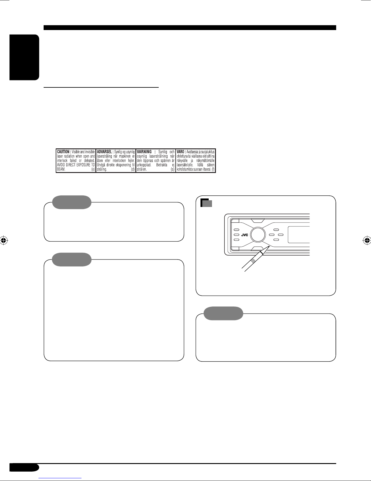
IMPORTANT FOR LASER PRODUCTS
1. CLASS 1 LASER PRODUCT
2. CAUTION: Do not open the top cover. There are no user serviceable parts inside the unit; leave
all servicing to qualified service personnel.
3. CAUTION: Visible and invisible laser radiation when open and interlock failed or defeated.
Avoid direct exposure to beam.
4. REPRODUCTION OF LABEL: CAUTION LABEL, PLACED OUTSIDE THE UNIT.
Warning:
If you need to operate the receiver while
driving, be sure to look ahead carefully or
you may be involved in a traffic accident.
Cautions:
• Do not insert 8 cm discs (single CDs) into
the loading slot. (Such discs cannot be
ejected.)
• Do not insert any disc of unusual shape—
like a heart or flower; otherwise, it will
cause a malfunction.
• Do not expose discs to direct sunlight or
any heat source or place them in a place
subject to high temperature and humidity.
Do not leave them in a car.
How to reset your unit
This will reset the microcomputer. Your
preset adjustments will also be erased.
Notice:
The display window built in this receiver
has been produced with high precision, but
it may have some ineffective dots. This is
inevitable and is not malfunction.
2
Page 3

Contents
How to reset your unit ........................... 2
How to read this manual ........................ 4
How to forcibly eject a disc ................... 4
How to change the display pattern ........ 5
How to enter the various menus ............ 5
Control panel — KD-SHX855 ...... 6
Parts identification ................................. 6
Remote controller —
RM-RK300 ............................. 7
Main elements and features ................... 7
Getting started ....................... 8
Basic operations ..................................... 8
Canceling the display demonstration ..... 9
Setting the clock .................................... 9
Radio operations ................... 10
Listening to the radio ............................. 10
Storing stations in memory .................... 11
Listening to a preset station ................... 12
Sound adjustments —
Preference settings
Setting the basic sound selection menu
—SEL ................................................ 29
..................... 28
Graphic displays .................... 32
Basic procedure ..................................... 32
Downloading the files ............................ 33
Deleting the files .................................... 34
Activating the downloaded files ............ 36
General settings — PSM ......... 37
Basic procedure ..................................... 37
Selecting the dimmer mode ................... 40
Other main functions ............. 41
Assigning titles to the sources ............... 41
Changing the control panel angle .......... 42
Detaching the control panel ................... 42
External component operations
Playing an external component .............. 43
... 43
ENGLISH
Disc/SD card operations ......... 13
Playing a disc in the receiver ................ 13
Playing discs in the CD changer ........... 14
Playing an SD card ............................... 15
Other main functions ............................. 17
Selecting the playback modes ................ 19
Sound adjustments — Daily use
Selecting the DSP modes—DSP ........... 21
Making sound natural ............................ 23
Using equalizer—EQ ............................. 24
Selecting preset sound modes
—Graphic EQ .................................... 25
Storing your own sound modes ............. 26
Adjusting Parametric EQ ....................... 27
... 21
Maintenance .......................... 44
More about this receiver ........ 45
Troubleshooting ..................... 49
Specifications ......................... 52
This receiver is equipped with digital
amplifier.
For safety....
• Do not raise the volume level too much, as
this will block outside sounds, making driving
dangerous.
• Stop the car before performing any
complicated operations.
Temperature inside the car....
If you have parked the car for a long time in
hot or cold weather, wait until the temperature
in the car becomes normal before operating the
unit.
3
Page 4
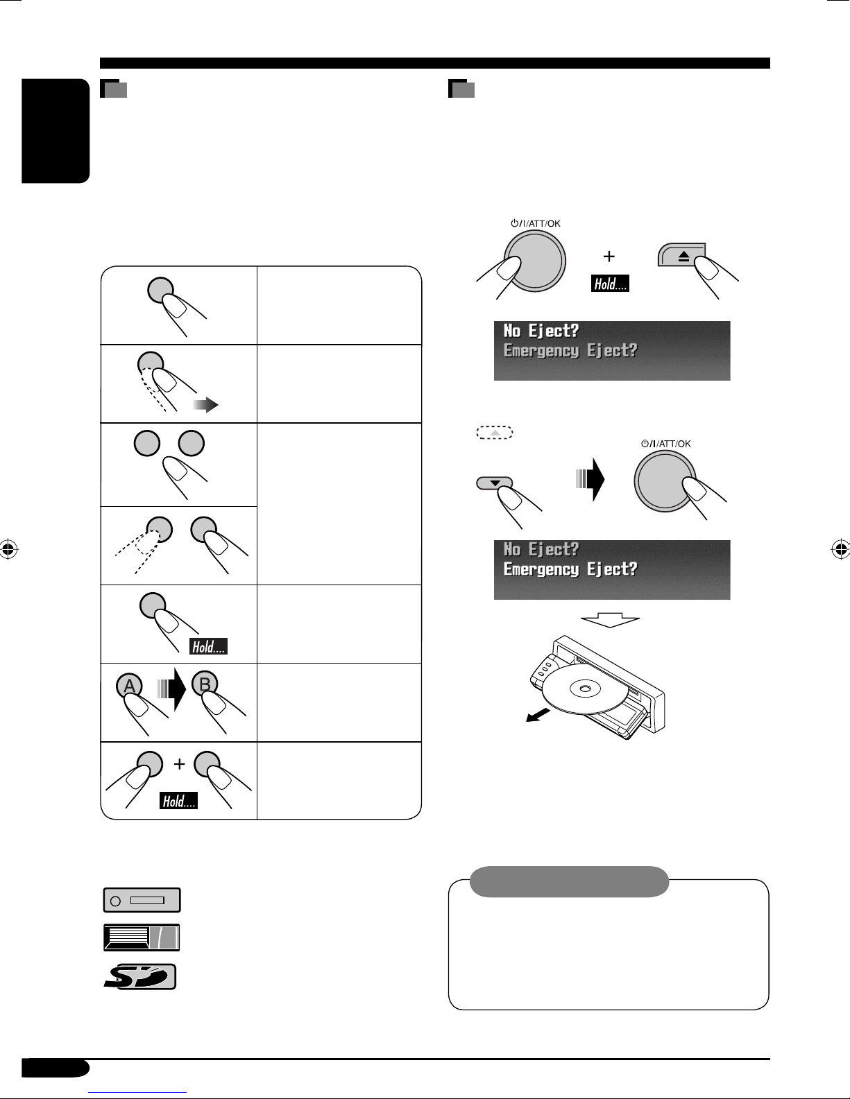
How to read this manual
How to forcibly eject a disc
The following methods are used to make the
explanations simple and easy-to-understand:
• Some related tips and notes are explained in
ENGLISH
“More about this receiver” (see pages
45 – 48).
• Button operations are mainly explained with
the illustrations as follows:
Press briefly.
Press repeatedly.
Press either one.
If a disc cannot be recognized by the receiver or
cannot be ejected, eject the disc as follows.
• If an SD card is inserted, eject the SD card
first (see page 15).
1
2
Press and hold until
your desired response
begins.
Press A, then press
B.
Press and hold both
buttons at the same
time.
The following marks are used to indicate...
: Built-in CD player operations.
: External CD changer operations.
: SD card operations.
• If this does not work, reset your receiver.
• Be careful not to drop the disc when it
ejects.
Caution on volume setting:
Discs produce very little noise compared
with other sources. Lower the volume
before playing a disc to avoid damaging
the speakers by the sudden increase of the
output level.
4
Page 5
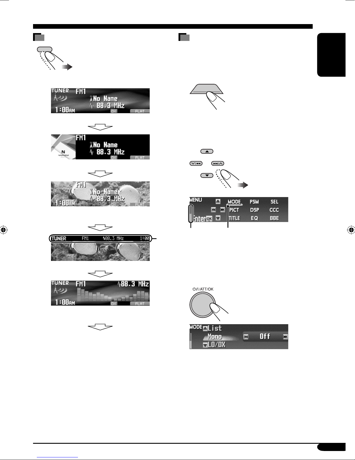
How to change the display pattern
DISP
Ex.: When tuner is selected as the source
How to enter the various menus
The main menu contains the following
menus—MODE, PSM, SEL, PICT, DSP, CCC,
TITLE, EQ, and BBE.
1
MENU
ENGLISH
Source operation screen
“Small” (CD jacket image) graphic*1 is displayed.
“Large” (full screen size) graphic*1 is shown as
the display background.
2
*
1
*
Graphic screen
2 Move the cursor to select a menu
you want (MODE, PSM, SEL, PICT,
DSP, CCC, TITLE, EQ, BBE).
*
• To go back to the previous screen, press
BACK.
* Works as time countdown indicator.
Cursor
3 Enter the selected menu.
Audio level meters are displayed
(see “LevelMeter” on page 37).
Goes back to the initial display pattern.
*1 You can use your edited file for graphic
screen (see pages 32 – 36).
Depending on a downloaded file, it may take
longer time to show it on the display.
2
*
The information bar will disappear if no
operation is performed.
Ex.: When MODE menu is selected
• To go back to the MENU screen, press
MENU.
4 Operate as instructed on the screen.
5
Page 6
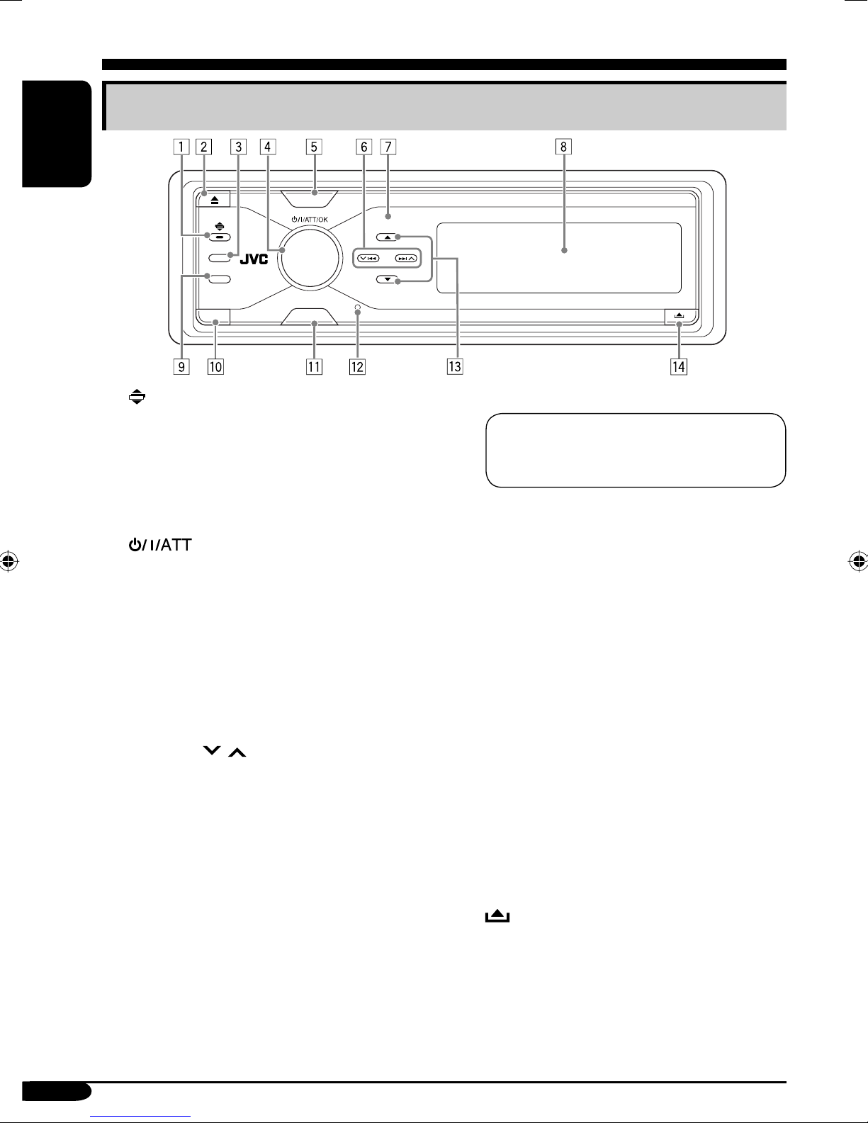
Control panel — KD-SHX855
Parts identification
ENGLISH
SOURCE
DISP
BACK
BAND
PICT
MENU
1 (angle) button
Adjusts the control panel angle.
2 0 (eject) button
Ejects the disc.
3 DISP (display) button
Changes the information shown on the
display.
4
(standby/on/attenuator)/OK
button
• Turns on and off the power and also
attenuates the sound.
• Confirms the selection while operating
the menus.
Volume control dial
Adjusts the volume level.
5 SOURCE button
Selects the source.
6 4/¢ (
/ ) buttons
• For FM/AM: Searches for stations if
pressed, or skips frequencies after pressed
and held.
• For discs or an SD card: Changes the
tracks if pressed, or fast-forwards or
reverses the track if pressed and held.
• For menu operations: Selects the menu
items/values.
7 Remote sensor
DO NOT expose the remote sensor on
the control panel to strong light (direct
sunlight or artificial lighting).
8 Color display window
9 BAND/BACK button
• For FM/AM: Selects the band.
• For menu operations: Goes back to the
previous screen.
p PICT (picture) button
Displays the PICT menu.
q MENU button
Displays the MENU screen.
w Reset button
e 5 (up) / ∞ (down) buttons
• For FM/AM: Changes the preset stations
if pressed, or displays Preset Station List
if pressed and held.
• For MP3/WMA discs or an SD card:
Changes the folders if pressed, or displays
Disc List (only for “CD-CH”) or Folder
List if pressed and held.
• For menu operations: Selects the menu
items/values.
r
(control panel release) button
6
Page 7
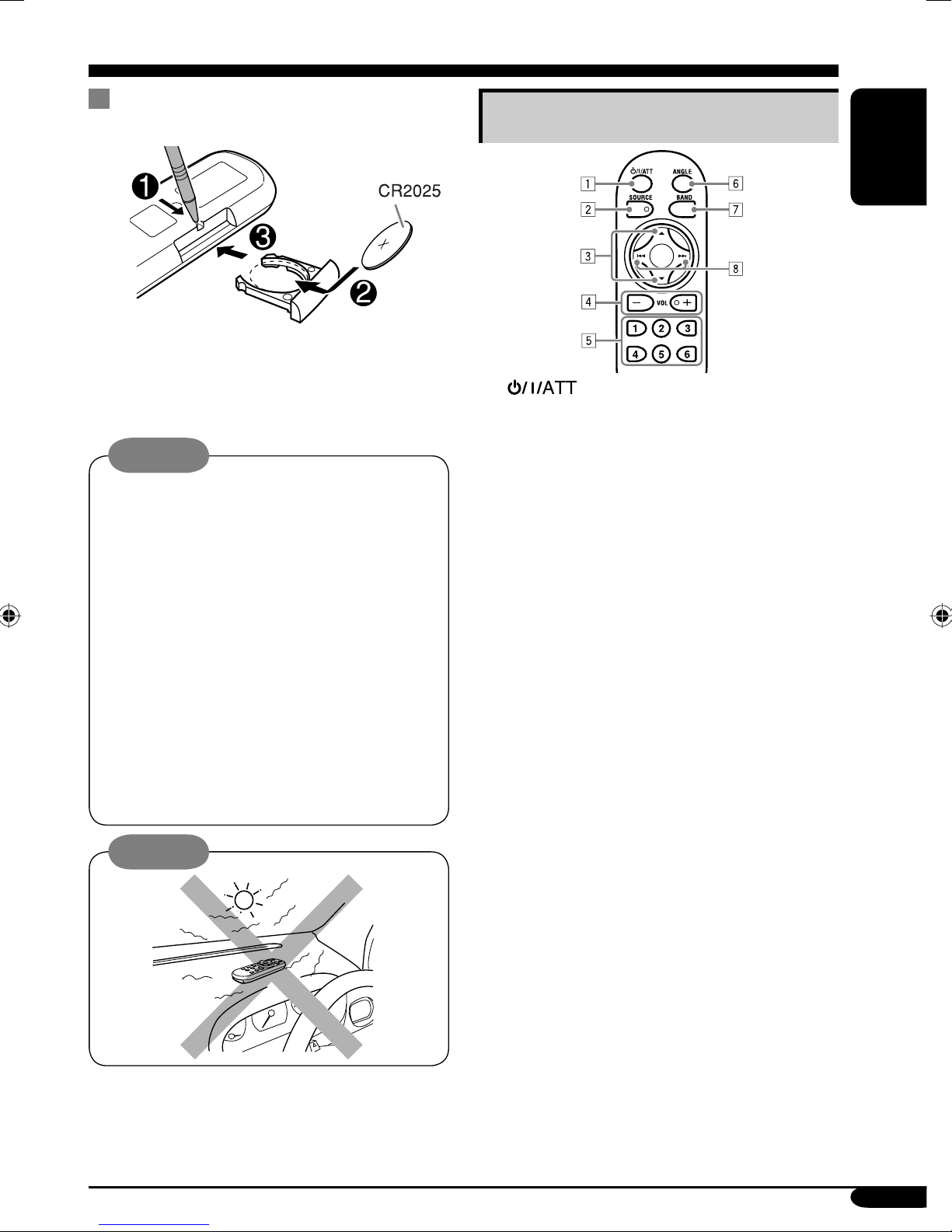
Remote controller — RM-RK300
Installing the lithium coin battery
(CR2025)
• When operating, aim the remote controller
directly at the remote sensor on the
receiver. Make sure there is no obstacle in
between.
Warning:
• Do not install any battery other than
CR2025 or its equivalent; otherwise, it
may explode.
• Store the battery in a place where children
cannot reach to avoid risk of accident.
• To prevent the battery from over-heating,
cracking, or starting a fire:
– Do not recharge, short, disassemble, or
heat the battery or dispose of it in a fire.
– Do not leave the battery with other
metallic materials.
– Do not poke the battery with tweezers or
similar tools.
– Wrap the battery with tape and insulate
when throwing away or saving it.
Caution:
Main elements and features
1 (standby/on/attenuator) button
Turns on and off the power and also
attenuates the sound.
2 SOURCE button
Selects the source.
3 5 (up) / ∞ (down) buttons
• For FM/AM: Changes the preset stations.
• For MP3/WMA discs or an SD card:
Changes the folders.
4 VOL (volume) + / – buttons
Adjusts the volume level.
5 Number buttons
• For FM/AM: Selects the preset station if
pressed, or store a station if pressed and
held.
• For audio CDs or CD Texts: Selects the
tracks.
• For MP3/WMA discs or an SD card:
Selects the folders.
• For CD changer: Selects the discs.
6 ANGLE button
Adjusts the control panel angle.
7 BAND button
Selects the band.
8 4 / ¢ buttons
• For FM/AM: Searches for stations if
pressed, or skips frequencies after pressed
and held.
• For discs or an SD card: Changes the
tracks if pressed, or fast-forwards or
reverses the track if pressed and held.
ENGLISH
7
Page 8
Getting started
ENGLISH
BACK
BAND
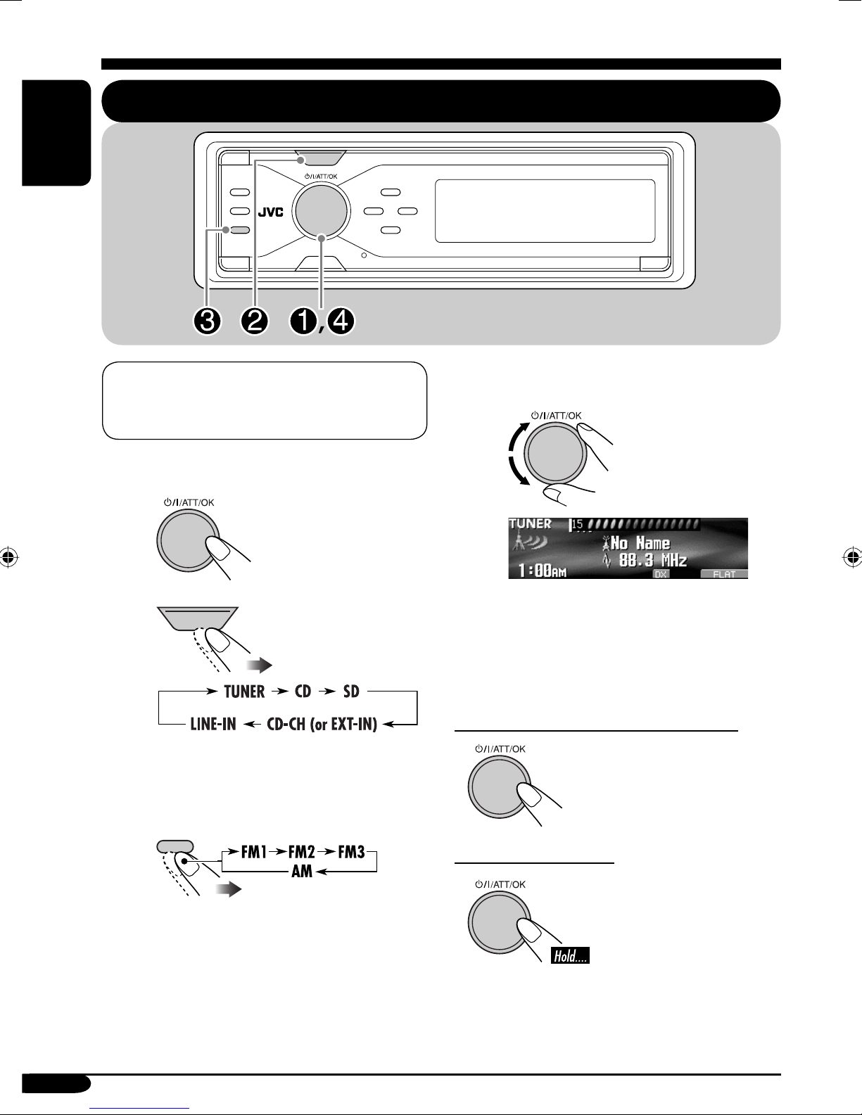
Basic operations
SOURCE
When activating or deactivating crossover
network (see page 28), perform before
turning on the power.
~ Turn on the power.
Ÿ
SOURCE
You cannot select some sources if they
are not ready.
! For FM/AM tuner
BACK
BAND
⁄ Adjust the volume.
@ Adjust the sound as you want.
(See pages 21 – 31.)
To drop the volume in a moment (ATT)
To restore the sound,
press it again.
To turn off the power
8
Page 9
Canceling the display
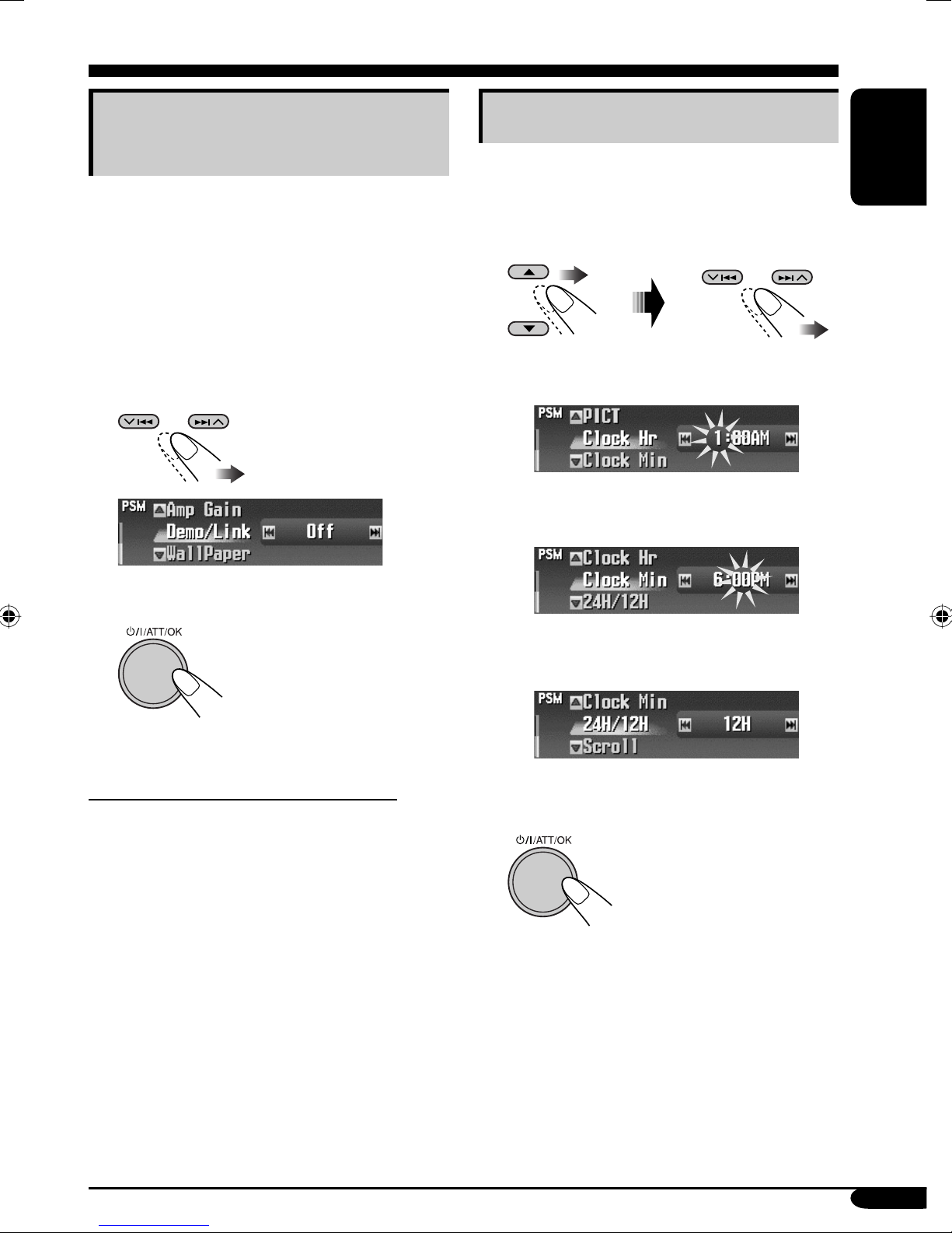
Setting the clock
demonstration
If no operations are done for about 45 seconds,
display demonstration starts.
[Initial: Demo]—see page 37.
1 Enter the PSM menu (see page
2 Select “Off.”
• Make sure “Demo/Link” is shown on the
display. If not, press 5 or ∞.
3 Finish the procedure.
5).
1 Enter the PSM menu (see page
5).
2 Set the hour, minute, and clock
system.
1 Select “Clock Hr” (hour), then
adjust the hour.
2 Select “Clock Min” (minute), then
adjust the minute.
ENGLISH
To activate the display demonstration
In step 2 above, select “Demo.” For more
details, see page 37.
3 Select “24H/12H,” then select
“24H” or “12H.”
3 Finish the procedure.
9
Page 10
Radio operations
ENGLISH
BACK
BAND
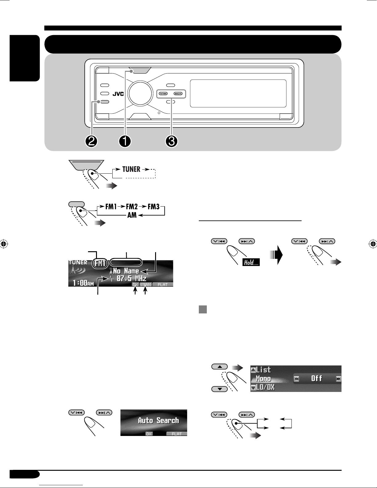
Listening to the radio
SOURCE
~
SOURCE
BACK
Ÿ
BAND
Current
band
Station frequency
1
*
To assign names to the stations, see
page 41.
*2 LO or DX indicator: See page 11.
*3 STEREO or MONO indicator:
• STEREO indicator lights up when
• For MONO, see the following
Preset
number
(if any)
receiving an FM stereo broadcast
with sufficient signal strength.
section.
Station name
assigned*1
3
*2*
When a station is received, searching
stops.
To stop searching, press the same
button again.
To tune in to a station manually
In step ! on the left...
Activate
“Manual Search”
Select station
frequencies
When an FM stereo broadcast is
hard to receive
1
Enter the MODE menu (see page 5).
2 Select “Mono.”
! Start searching for a station.
10
3 Select “On.”
Off
On
Page 11
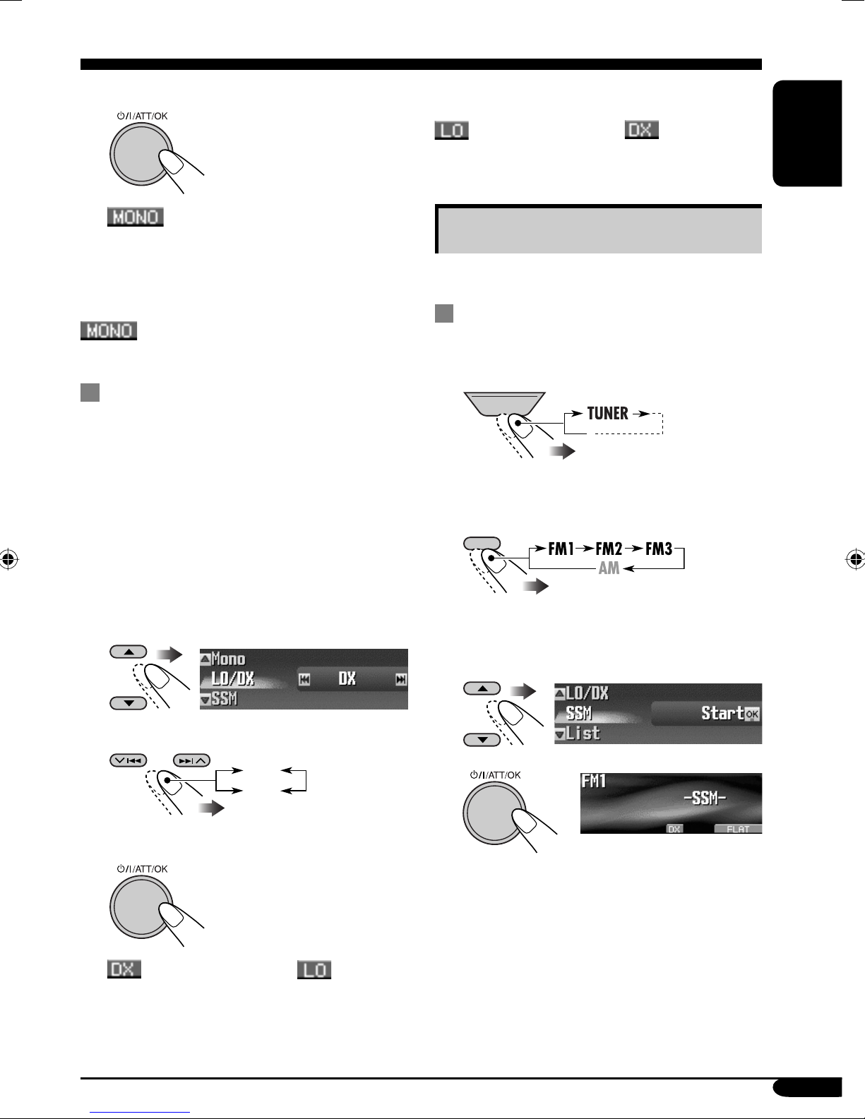
4 Finish the procedure.
indicator lights up.
Reception improves, but stereo effect will
be lost.
To restore the stereo effect, repeat the same
procedure and select “Off” in step 3.
indicator goes off.
To tune in to all receivable stations, repeat the
same procedure and select “DX” in step 3.
indicator goes off and indicator
lights up.
ENGLISH
Storing stations in memory
You can preset six stations for each band.
FM station automatic presetting —
SSM (Strong-station Sequential
Memory)
To tune in FM stations only with
strong signals—LO/DX (Local/
Distance-extreme)
If received signals are weak, you may only
hear noises. You can make this unit detect only
stations with sufficient signal strength while
searching for FM stations.
1 Enter the MODE menu (see page 5).
2 Select “LO/DX.”
3 Select “Local.”
DX
Local
1
2
SOURCE
Select the FM band (FM1 – FM3)
you want to store into.
BACK
BAND
3 Enter the MODE menu (see page
4 Select “SSM.”
5
5).
4 Finish the procedure.
indicator goes off and indicator
lights up.
Only stations with sufficient signal strength
will be detected.
Local FM stations with the strongest signals are
searched and stored automatically in the FM
band.
To be continued....
11
Page 12
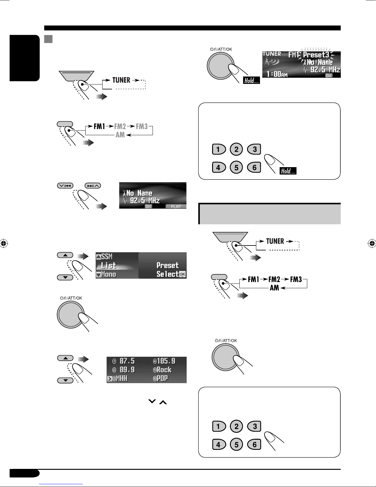
Manual presetting
Ex.: Storing FM station of 92.5 MHz into preset
number 3 of the FM1 band.
1
ENGLISH
SOURCE
8 Store the station.
BACK
2
BAND
• If you hold 5/∞, the Preset Station List
will appear (see step 7 below).
3
4 Enter the MODE menu (see page
5 Select “List.”
5).
When using the remote controller...
After tuning in to a station you want to
preset
Listening to a preset station
1
2
SOURCE
BACK
BAND
6
7 Select a preset number.
• You can move to the lists of the other FM
bands by pressing 4/¢ (
12
/ ).
3 Perform steps 4 to 7 (on left column)
to enter the Preset Station List.
4
When using the remote controller...
To directly select the preset number
Page 13
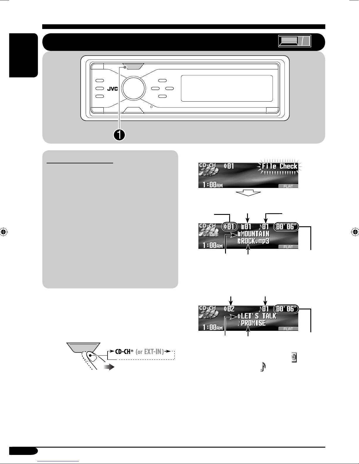
Disc/SD card operations
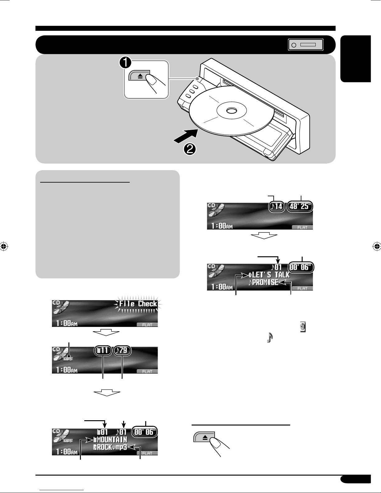
Playing a disc in the receiver
All tracks will be
played repeatedly until
you change the source
or eject the disc.
ENGLISH
About MP3 and WMA discs
• When an MP3 or a WMA folder includes
an image <jpw> file edited by Image
Converter (Color Ver. 2.0)—supplied in
the CD-ROM, you can show the image on
the display while the tracks in the folder
are played back—ImageLink. (See pages
37 and 47 for details.)
• MP3 and WMA (Windows Media
“tracks” (words “file” and “track” are used
interchangeably) are recorded in “folders.”
• When inserting an MP3 or a WMA disc:
File type
Total folder number
Current folder
number
1
*
Total track number
Current
track
number
®
Audio)
Elapsed
playing
time
• When inserting an audio CD or a CD Text
disc:
Total track number
Current track
number
Disc name*
1
*
Either the MP3 or WMA indicator lights up
3
Total playing time
Elapsed
playing time
Track name*
4
depending on the detected file.
2
*
The album name/performer with indicator
and the track title with
indicator will appear
if “Tag” is set to “On” (see page 38).
3
*
Appears only for CD Texts and CDs if it has
been recorded or assigned. (“No Name”
appears if no name is recorded or assigned
to an audio CD.)
4
*
Appears only for CD Texts. (“No Name”
appears if no name is recorded.)
To stop play and eject the disc
Folder name*
2
Track name*
To return the control panel to
its previous position, press it
again.
2
13
Page 14
Playing discs in the CD changer
SOURCE
ENGLISH
About the CD changer
It is recommended to use the JVC MP3compatible CD changer with your receiver.
• You can also connect other CH-X series
CD changers (except CH-X99 and
CH-X100). However, they are not
compatible with MP3 discs, so you cannot
play back MP3 discs.
• You cannot use the KD-MK series CD
changers with this receiver.
• Disc text information recorded in the CD
Text can be displayed when a JVC CD
Text compatible CD changer is connected.
• You cannot control and play any WMA
disc in the CD changer.
All tracks of the inserted discs in the magazine
will be played repeatedly until you change
the source or eject the magazine from the CD
changer.
• When the current disc is an MP3 disc:
Current disc
number
Folder name*
Current folder
number
1
Track name*
Current track
number
Elapsed
1
playing time
• When the current disc is an audio CD or a
CD Text disc:
Current track numberCurrent disc number
~
SOURCE
If you have changed “Ext Input”
*
setting to “Ext Input” (see page 39),
you cannot select the CD changer.
14
Elapsed
2
Disc name*
1
*
The album name/performer with indicator
Track name*
and the track title with
3
playing time
indicator will appear
if “Tag” is set to “On” (see page 38).
2
*
Appears only for CD Texts and CDs if it has
been recorded or assigned. (“No Name”
appears if no name is recorded or assigned
to an audio CD.)
3
*
Appears only for CD Texts. (“No Name”
appears if no name is recorded.)
Page 15
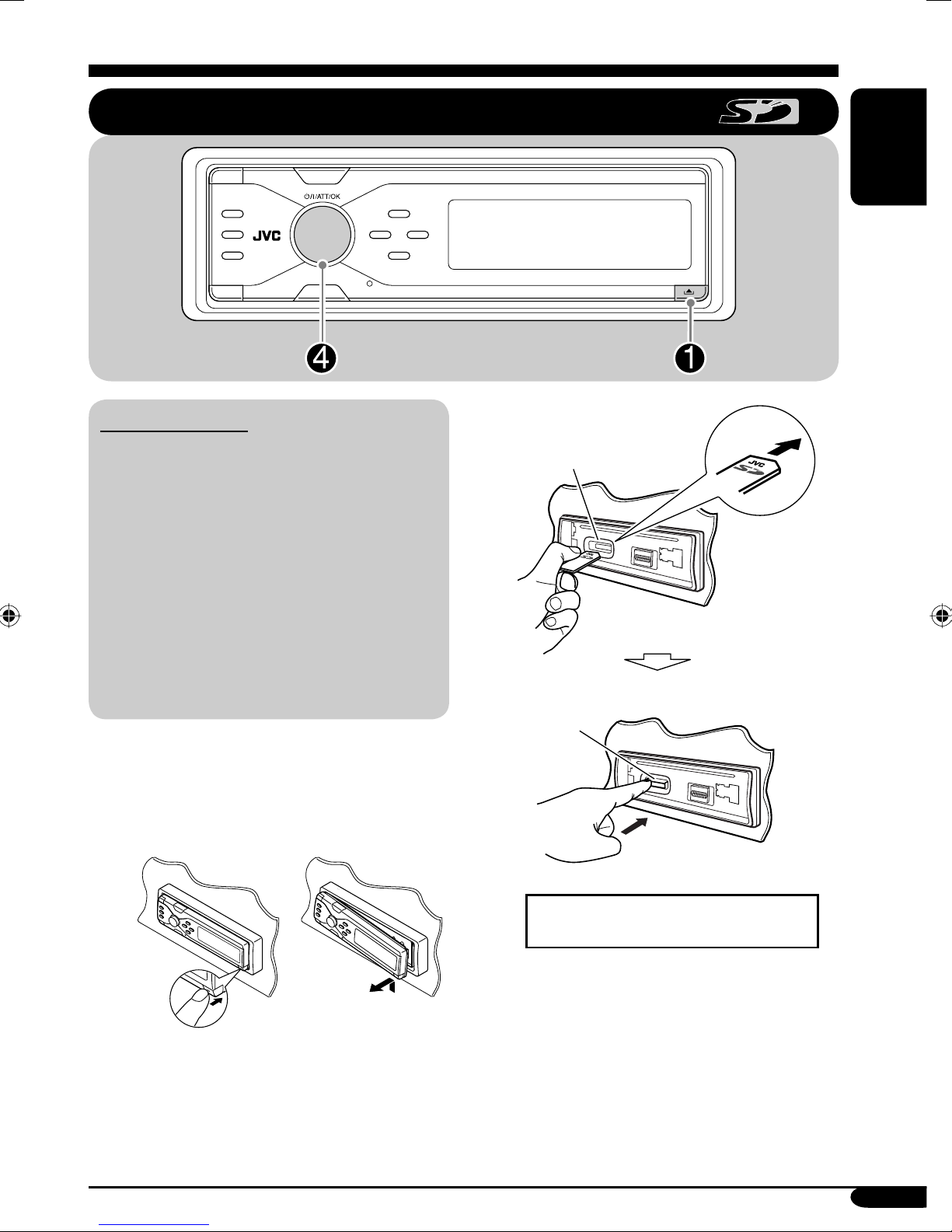
Playing an SD card
ENGLISH
About the SD card
• When an MP3 or a WMA folder includes
an image <jpw> file edited by Image
Converter (Color Ver. 2.0)—supplied in
the CD-ROM, you can show the image on
the display while the tracks in the folder
are played back—ImageLink. (See pages
37 and 47 for details.)
• The required SD recording format is FAT
12/16 and the recommended storage type is
8 MB to 512 MB.
• You cannot use MMC or mini SD with this
receiver.
Before detaching the control panel, turn off the
power.
~ Detach the control panel.
Ÿ
SD loading slot
SD card
Press in the SD card until you hear
a clicking sound.
To eject the SD card, press the SD
card again.
• Press the SD card softly (do not
release your finger quickly);
otherwise, the SD card may pop out
from the unit.
To be continued....
15
Page 16
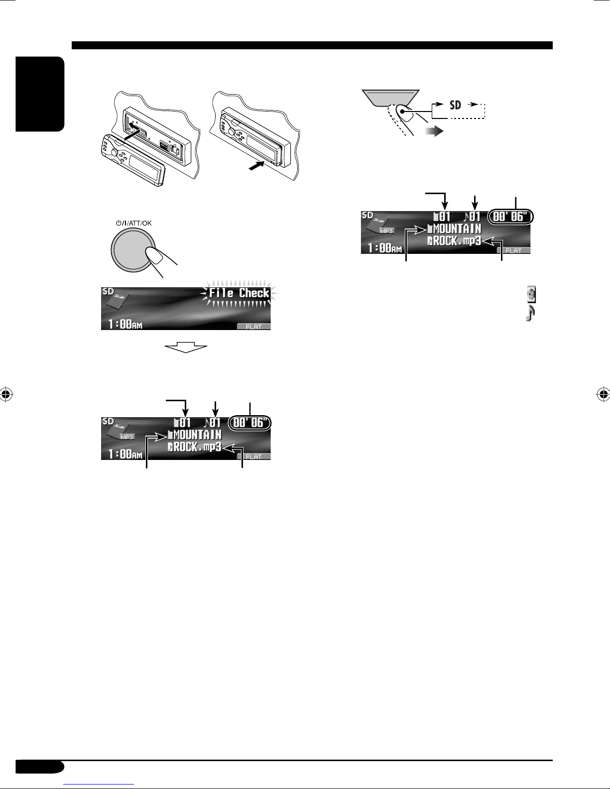
! Attach the control panel.
ENGLISH
If an SD card has been loaded....
1
SOURCE
⁄ • The control panel goes
back to the previous
position (see page 42).
Current
folder
number
Current
track
number
Elapsed
playing
time
2
Current
folder
number
Folder name
* The album name/performer with
indicator and the track title with
indicator will appear if “Tag” is set
to “On” (see page 38).
*
Current
track
number
Track name*
Elapsed
playing
time
Folder name
Playback starts automatically if tracks
are recorded.
*
Track name*
16
Page 17
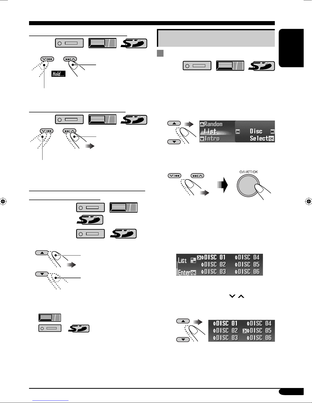
To fast-forward or reverse the track
Fast-forwards.
Reverses.
To go to the next or previous tracks
To the following
tracks.
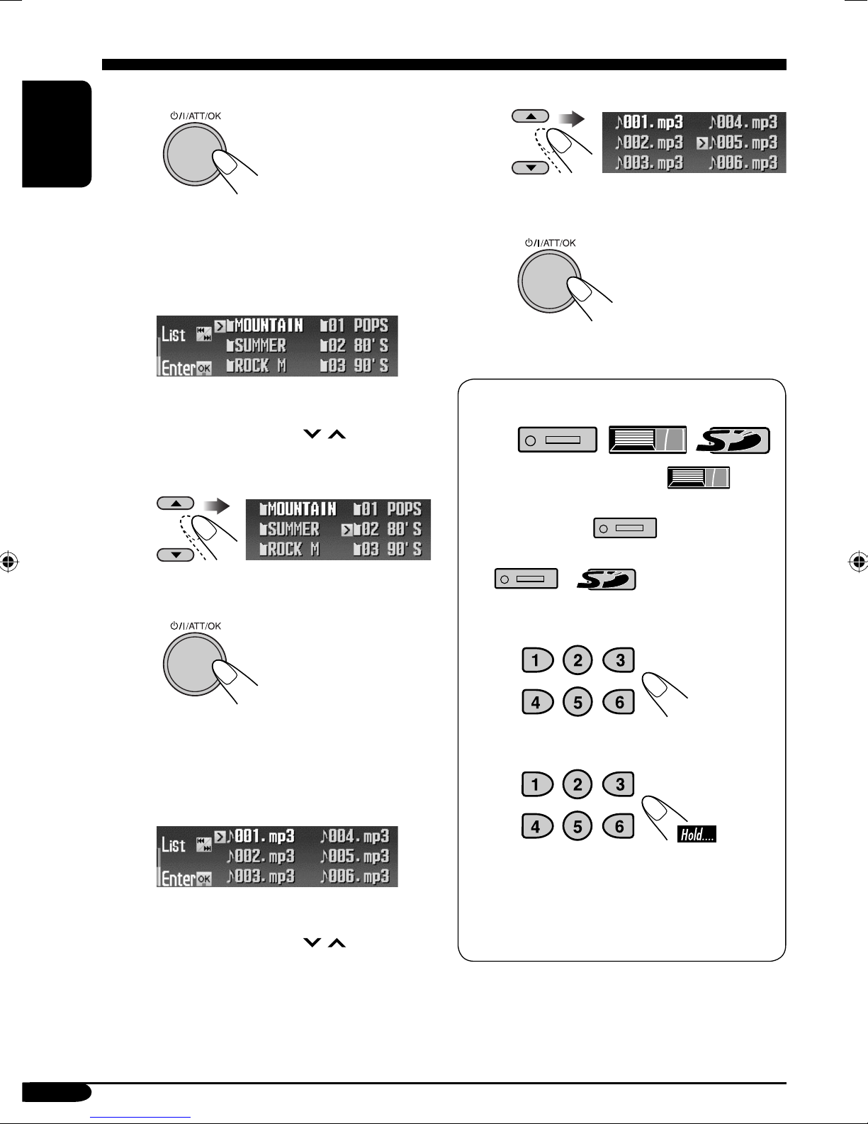
Other main functions
Selecting a disc/folder/track on the
list
• This function is not available for an audio CD
or a CD Text when the source is “CD.”
1 Enter the MODE menu (see page
2 Select “List.”
5).
ENGLISH
To the beginning of the current track, then
the previous tracks.
To go to the next or previous folders (only
for MP3 and WMA tracks)
For MP3 tracks:
For WMA tracks:
To next folders.
To previous folders.
3 Select the list type—“Disc,”*
“Folder,”*2 or “File.”*
*1 Selectable only when the source is
“CD-CH.”
2
*
Appears only for MP3/WMA files.
1 When “Disc” is selected:
Disc List appears.
• You can move to the other list by
pressing 4/¢ (
2
/ ).
1
• Holding the buttons can display the Disc List
(
(
section).
) and Folder List
/ ) (see the following
To select a disc
To be continued....
17
Page 18
To start playback
ENGLISH
To select a file
• Only for MP3: If you select the
current disc (highlighted on the
screen), its Folder List appears.
2 When “Folder” is selected:
Folder List appears.
• You can move to the other lists by
pressing 4/¢ (
/ ).
To select a folder
To start playback
To start playback
When using the remote controller...
• To directly select a disc ( )
• To directly select a track of an audio CD
or a CD Text (
• To directly select an MP3/WMA folder
(
To select a number from 1 – 6:
/ )
)
• If you select the current folder
(highlighted on the screen), its File
List appears.
3 When “File” is selected:
File List appears.
• You can move to the other lists by
pressing 4/¢ (
18
/ ).
To select a number from 7 (1) – 12 (6):
• For MP3/WMA folders:
It is required that folders are assigned with
2-digit number at the beginning of their
folder names—01, 02, 03, and so on.
Page 19

Prohibiting disc ejection
You can lock a disc in the loading slot.
1
Selecting the playback modes
ENGLISH
You can use only one of the following playback
modes at a time.
2 After making sure “No Eject?” is
selected (highlighted)...
“No Eject” flashes, and the disc cannot be
ejected.
To cancel the prohibition
Repeat the same procedure, press
in step 2 after making sure that “Eject OK?” is
selected (highlighted).
“Eject OK” flashes.
1 Enter the MODE menu (see page
5).
2 Select one of the playback modes —
“Intro,” “Repeat,” or “Random.”
3 Select your desired playback modes.
• For details, see table
on page 20.
4 Finish the procedure.
To be continued....
19
Page 20

Intro play
ENGLISH
Ex.: When “Track” is selected while
playing an MP3 disc in the
receiver
Mode Plays the beginning 15 seconds of...
Trac k: All tracks of the current disc or the
SD card.
• While playing,
up.
Folder*
1
: First tracks of all folders of the
current disc or the SD card.
• While playing,
up.
Disc*
2
: First tracks of all the inserted discs.
• While playing,
up.
Off: Cancels.
lights
lights
lights
Repeat play
Ex.: When “Track” is selected while
playing an MP3 disc in the
receiver
Random play
Ex.: When “Disc” is selected while
playing an MP3 disc in the
receiver
Mode Plays repeatedly
Trac k: The current track.
• While playing,
lights
up.
Folder*
1
: All tracks of the current folder.
• While playing,
lights
up.
Disc*
2
: All tracks of the current disc.
• While playing,
lights
up.
Off: Cancels.
Mode Plays at random
Folder*1: All tracks of the current folder, then
tracks of the next folder and so on.
• While playing,
up.
Disc: All tracks of the current disc.
• While playing,
up.
SD: All tracks of the SD card.
• While playing,
up.
2
All*
: All tracks of the inserted discs.
• While playing,
up.
Off: Cancels.
lights
lights
lights
lights
1
*
Only while playing an MP3 ( / / ) or a WMA ( /
) track.
2
Only while playing a disc in the CD changer ( ).
*
20
Page 21

Sound adjustments — Daily use
Selecting the DSP modes —DSP
MENU
You can create a more acoustic sound field such
as in a theater, hall, etc.
• When crossover network (see page 28) is
activated, the DSP mode is fixed to “Defeat.”
! Adjust the effect level (1 – 3).
ENGLISH
Available DSP modes
Defeat (No acoustic effect is applied),
Theater, Hall, Club, Dome, Studio,
V.C ancel (Voice Cancel: Reduces the
vocal sounds. Good for mastering your
favorite songs—Karaoke.)
~ Enter the DSP menu (see page
Ÿ Select one of the DSP modes.
Ex.: When “Theater” is selected
• To finish the procedure
DISP
5).
• For “Defeat” and “V.Cancel,” the
effect level is not adjustable.
• As the number increases, the effect
level becomes stronger.
• To finish the procedure
DISP
• To make further precise settings
\ See page 22.
To cancel the acoustic effect, select
“Defeat” in step Ÿ.
• To adjust the effect level
\ Go to step !.
21
Page 22

To make further precise settings for
the DSP modes
Setting items:
ENGLISH
The number of the built-in speakers:
Select the number of the speakers built in
your car—“2ch” or “4ch.”
Time alignment:
Set the distance between each speaker and
the listening seat position.
4 Select the speaker to be adjusted.
L.Front:
R.Front:
L.Rear*:
R.Rear*:
For left front speaker.
For right front speaker.
For left rear speaker.
For right rear speaker.
1 Repeat steps ~ to ! on page 21 to
select DSP mode.
2 Select the number of the built-in
speakers.
• For “Defeat” and “V.Cancel,” the speaker
number is fixed to “4ch.”
4ch:
2ch:
Select for the four speaker system.
Select for the two speaker system.
3 Select your listening seat position.
Subwoofer:
* Appears only when “4ch” is selected in
step 2.
For subwoofer.
5 Select distance between the selected
speaker and the seat.
• You can change the measuring unit to
inch by holding DISP.
Each time you press and hold the button,
the unit alternates between centimeter
(cm) and inch.
• 0 cm to 400 cm
(0 inch to 160 inch)
in 5 cm (2 inch)
intervals
• Once you have set the distance, it is
memorized for each seat position selected
in step 3. The memorized setting are
recalled next time you select the seat
position.
All:
Front:
R.Front:
L.Front:
22
For all front and rear seats.
For the both front seats.
For the front right seat.
For the front left seat.
6 Repeat steps 4 and 5 to adjust the
distance for the other speakers.
7 Finish the procedure.
Page 23

Making sound natural
To activate Compression
Compensative (CC) Converter
CC Converter eliminates jitter and ripples,
achieving a drastic reduction in digital
distortion. This processing can be applied to the
analog sources as well as the digital sources;
therefore, you can obtain a natural sound field
from any source.
1 Enter the CCC menu (see page 5).
To activate BBE Digital
BBE Digital* is a digital processing method to
restore the brilliance and clarity of the original
live sound in recording, broadcasts, etc.
When a speaker reproduces sound, it introduces
frequency-dependent phase shifting, causing
high-frequency sounds to take longer to reach
the ear than low frequency sounds. BBE Digital
adjusts the phase relationship between the
low, mid and high frequencies by adding a
progressively longer delay time to the low and
mid frequencies, so that all frequencies reach
the listener’s ears at the proper time.
ENGLISH
2 Select “On.”
Off
On
• When “C.C.Conv.” is turned on, the
CCC indicator is brightened in yellow
on the display (in sequence with other
indicators).
• To cancel CC Converter, select “Off.”
3 Finish the procedure.
1 Enter the BBE menu (see page 5).
2
Select the effect level.
Off 1
23
Ex.: When “1” is selected
• As the number gets higher, the effect
level becomes stronger. When “BBE”
is turned on, the BBE indicator is
brightened in green (with its current level)
on the display (in sequence with other
indicators).
• To cancel BBE Digital, select “Off.”
3 Finish the procedure.
* Manufactured under license from BBE Sound,
Inc.
Licensed by BBE Sound, Inc. under USP5510752
and 5736897. BBE and BBE symbol are
registered trademarks of BBE Sound, Inc.
23
Page 24

Using equalizer —EQ
ENGLISH
MENU
You can adjust the sound equalization patterns
to your preference by using two EQ modes—
Graphic EQ and Parametric EQ.
Graphic EQ: You can select a preset sound
mode suitable to the music genre. You can
also store your own adjustments in memory.
~ Enter the EQ menu (see page
Ÿ Select “Graphic” or
“Parametric.”
5).
Parametric EQ: You can adjust the
enhanced level, bandwidth, and center
frequencies at three bands. You can make
more precise settings than using Graphic EQ.
• Adjust the equalizer to match the reproducible
frequency range of the connected speakers;
otherwise, the adjustments may not be
effective.
• You cannot activate both Graphic EQ and
Parametric EQ at the same time.
!
• To select preset sound modes
\ See page 25.
• To adjust the sound mode and store
your own adjustment in memory
\ See page 26.
• To adjust Parametric EQ
\ See page 27.
24
Page 25

Selecting preset sound modes
—Graphic EQ
Available sound modes
Flat (No sound mode is applied),
Hard Rock, R&B (Rhythm&Blues),
Pop, Jazz, Dance, Country, Reggae,
Classic, User 1, User 2, User 3
2 Select a sound mode.
ENGLISH
Ex.: When “Flat” is selected
• For User 1/2/3, you can store your own
adjustment (see page 26).
3 Finish the procedure.
DISP
1 Follow steps ~ to ! on page 24.
• In step Ÿ, select “Graphic.”
The list below shows the preset frequency level settings for each sound mode:
Sound Preset equalizing values
Mode
Flat 00 00 00 00 00 00 00 00 00
63 Hz 125 Hz 250 Hz 500 Hz 1 kHz 2 kHz 4 kHz 8 kHz
12.5 kHz
Hard Rock +06 +06 +04 +02 00 00 +02 +04 +02
R&B +06 +04 +04 +04 00 +02 +02 +02 +06
Pop 00 +04 +02 00 00 +02 +02 +02 +04
Jazz +06 +04 +02 +02 +02 +02 +02 +06 +04
Dance +08 +04 +02 00 –04 –02 00 +02 +02
Country +04 +02 00 00 00 00 00 +02 +04
Reggae +06 +02 00 00 +02 +04 +04 +04 +06
Classic +04 +06 +04 +02 00 00 +02 +04 00
User 1 00 00 00 00 00 00 00 00 00
User 2 00 00 00 00 00 00 00 00 00
User 3 00 00 00 00 00 00 00 00 00
25
Page 26

Storing your own sound modes
6 Repeat steps 4 and 5 to adjust the
other frequency bands.
1 Follow steps ~ to ! on page 24.
ENGLISH
• In step Ÿ, select “Graphic.”
2 Select a sound mode
Ex.: When “Flat” is selected
.
3
4 Select the frequency band—63 Hz,
125 Hz, 250 Hz, 500 Hz, 1 kHz,
2 kHz, 4 kHz, 8 kHz, 12.5 kHz.
7
8 Select one of the user modes—
User 1/2/3.
9 Store the adjustments.
5 Adjust the enhanced level for the
selected frequency band within the
range of –10 to +10.
26
Ex.: When “User 1” is selected
Page 27

Adjusting Parametric EQ
1 Follow steps ~ to ! on page 24.
• In step Ÿ, select “Parametric.”
2 Select the band—Band1/2/3.
Select the frequency (adjustable
5
between 20 Hz – 20 kHz).
• Band 1/2/3 are required to be preset at
least 5 steps (frequencies) away from each
other. (Only selectable frequencies are
shown on the display.)
Ex.: When “1 kHz” is selected for “Band2”
ENGLISH
Band1:
Band2:
Band3:
Low band (20 Hz to 1.2 kHz)
Mid band (80 Hz to 5 kHz)
High band (315 Hz to 20 kHz)
3 Adjust the enhanced level for the
selected band within the range of –10
to +10.
4
Not selectable
6 Select the band width (Q)—
0.7/1/2/3/4/5.
• To adjust the other bands, press BACK.
Then repeat steps 2 to 6.
7 Finish the procedure.
• Once you have made adjustments, it is
memorized. The memorized setting is recalled
next time you select Parametric EQ.
27
Page 28

Sound adjustments — Preference settings
Activating crossover network
Crossover network function enables to allocate
sound signals to different speakers by frequency
range.
ENGLISH
By activating crossover network, you can make
precise adjustments to match the characteristic
of each speaker. (See “To adjust reproduced
frequency level—Crossover” on page 30.)
If you have installed the 3-way network
speaker system in the car, make sure of
the following.
• Before using the system, activate crossover
network and preset the appropriate cutoff
frequencies for HPF/LPF (especially
for HPF); otherwise, it may damage the
speakers.
• For 3-way network speaker system, see
Installation/Connection Manual (separate
volume).
• Until you finish the following procedure, you
cannot perform other operations.
While the power is turned off...
1
3 Finish the procedure.
• indicator lights up (in
sequence with other indicators).
To cancel Crossover
Repeat the same procedure.
Make sure that “Crossover Off?” appears on the
display in step 1 and “Crossover Off OK?” in
step 2.
•
Adjustable items for crossover network
You can adjust the following parameters for
crossover network. For details, see pages 30
and 31.
• HPF (high pass filter): For front/rear
speakers.
• LPF (low pass filter): For rear speakers
and subwoofer*.
• Slope (filter attenuation slope): For front/
rear speakers and subwoofer*.
indicator goes off.
(Press any button)
2
• To cancel the procedure, press and hold
. The power turns off.
28
* You can adjust LPF and slope for
subwoofer even though crossover network
is deactivated.
How crossover parameters actually
work
Reproduced frequency band
Slope
Frequency
Cut off
frequency of
HPF
Cut off
frequency of
LPF
Page 29

Setting the basic sound selection menu—SEL
MENU
You can adjust the sound characteristics to your
preference.
ENGLISH
! Adjust the selected setting item.
~ Enter the SEL menu (see page
5).
Ÿ Select a setting item—“Fad/Bal,”
“Crossover*,” “Subwoofer,” or
“VolAdjust.”
Ex.: When “Fad/Bal” is selected
* Appears only when crossover network
is activated (see page 28).
When selecting “Fad/Bal,”
“Crossover,” or “Subwoofer,”
press
submenu.
to enter the its
• To adjust other SEL settings, press
BACK. Then repeat steps Ÿ and !.
⁄ Finish the procedure.
29
Page 30

To adjust fader and balance
—Fad/Bal
ENGLISH
Adjust the fader*—speaker output balance
between the front and rear speakers.
* When crossover network is activated, speaker
output balance between high-range and midrange speakers is adjusted.
• F12: Upmost—front only
• R12: Downmost—rear
only
Adjust the balance—speaker output balance
between the left and right speakers.
Select “ON” or “OFF.”
• If you connect high-range speakers to
Front or Rear output, select “ON” for the
corresponding HPF; otherwise, the speakers
may be damaged.
• ON / OFF
ON:
OFF:
Activates the filter.
\ Press
reproduced frequency level and
slope (see below).
Deactivates the filter.
\ Press
“Filter Off OK?” appears, then press
to adjust
.
again.
• L12: Leftmost—left only
• R12: Rightmost—right
only
To adjust reproduced frequency
level—Crossover
• This setting is available only when crossover
network (see page 28) is activated.
To activa te the fi lters (HPF/LPF)
Select an item.
• Front HPF / Rear LPF /
Rear HPF
• For Front HPF and Rear HPF: Frequencies
lower than the selected level are cut off.
• For Rear LPF: Frequencies higher than the
selected level are cut off.
To select the cutoff frequency
Select an appropriate cutoff frequency level
according to speakers.
• 1.6 kHz to 16 kHz:
For Front HPF and Rear
LPF
• 31.5 Hz to 200 Hz:
For Rear HPF
To adjus t the slope
Adjust the slope—continuity of sound among
speakers.
• –18 / –12 / –6 (dB)
Front HPF:
Rear LPF:
Rear HPF:
30
Adjusts HPF for front speakers.
Adjusts LPF for rear speakers.
Adjusts HPF for rear speakers.
• As the number becomes higher, the
reproduced band width shared among
speakers becomes wider.
Page 31

To adjust subwoofer output—
To adjust the input level of each
Subwoofer
To adjus t subwoofer level
Adjust the subwoofer output level.
• 00 (min.) to 12 (max.)
• Press
frequency level and slope.
To select the cutoff frequency
Select an appropriate cutoff frequency level
according to the subwoofer connected.
to adjust reproduced
source—VolAdjust
ENGLISH
This setting is required for each source except
FM. Before making an adjustment, select an
appropriate source for which you want to make
an adjustment.
Once you have made an adjustment, it
is memorized, and the volume level will
automatically increase or decrease by adjusted
level whenever you change the source.
Adjust to match the input level to the FM sound
level.
• –5 (min.) to +5 (max.)
• 31.5 Hz to 200 Hz
• Frequencies higher than the selected level are
cut off to the subwoofer.
To adjus t the slope
Adjust the slope—continuity of sound among
speakers.
• –18 / –12 / –6 (dB)
• As the number becomes higher, the
reproduced band width shared among
speakers becomes wider.
31
Page 32

Graphic displays
ENGLISH
MENU
Before starting the following procedure,
prepare a CD-R or an SD card including still
images (pictures) and animations (movies).
• With Image Converter (Color Ver. 2.0)
included in the supplied CD-ROM, you can
create your own images and animations.
(Samples are included in the CD-ROM.)
• You can store two sizes of picture and
animation—“Large” and “Small” as the
graphic display (see page 5).
Basic procedure
! Select the picture size—“Large”
or “Small.”
Large
Small
~ Insert a CD-R, an SD card, or the
supplied CD-ROM.
• CD-R/supplied CD-ROM
• SD card
Ÿ Enter the PICT menu (see page 5).
• If you press PICT, you can enter the
PICT menu directly.
⁄
@ Select the item.
Ex.: When “Delete” is selected
• To download the file(s):
\ “Download” (see page 33)
• To delete the file(s):
\ “Delete” (see page 34)
• To delete all files:
\ “AllDelete” (see page 35)
• To activate the file(s):
\ Activating the downloaded files
(see page 36)
32
Page 33

IMPORTANT:
• Refer also to Image Converter PDF files
included in the “Manual” folder on the
supplied CD-ROM.
• Still images (pictures) and animations
(movie) should have the following
extension code in their file names:
– jpl: for large size still images
– jpm: for small size still images
– jpa: for large size animations
– jpb: for small size animations
– jpw: for ImageLink (see pages 37 and 47)
• Before you download or delete the files,
observe the following:
– Do not download a file while driving.
– Do not turn off the ignition key of the
car while downloading or deleting a
file.*
– Do not detach the control panel while
downloading or deleting a file.*
* If you do so, the file download or deletion
will not be done correctly.
2 Select the file type—either “Picture”
or “Movie.”
The Folder List appears.
3 Select a folder.
• You can move to the other lists by
pressing 4/¢ (
/ ).
ENGLISH
Downloading the fi les
• Picture: Graphic screen
To download/delete still images (16 still
images each for large size and for small size)
which will be shown while playing a source.
• Movie: Graphic screen
To download/delete animations (60 frames
each for large size and for small size) which
will be shown while playing a source.
Downloading pictures or animations
• It takes a long time to download an animation.
For details, see page 48.
• To activate the downloaded files, see page 36.
1 Follow steps ~ to @ on page 32.
• In step !, select the picture size.
• Then in step @, select “Download.”
The File List appears.
4 Select a file.
• You can move to the other lists by
pressing 4/¢ (
/ ).
To be continued....
33
Page 34

5 Download the file.
ENGLISH
• To cancel downloading, press DISP.
• When download is complete, the File List
appears again.
6 • To download more pictures from
the same folder, repeat steps 4 and
5.
• To download more pictures from
another folder, press BACK. Then,
repeat steps 3 to 5.
7 Finish the procedure.
DISP
3 • To delete the stored pictures
1
2
Select “Delete.”
The File List appears.
Deleting the fi les
Deleting the stored pictures and
animations
1
Follow steps ~ to @ on page 32.
• In step !, select the picture size.
• Then in step @, select “Delete.”
2 Select the file type—either “Picture”
or “Movie.”
3
4
5
Select a file.
• You can move the other lists by
pressing 4/¢ (
• When a file is deleted, the File List
appears again.
/ ).
Repeat steps 3 and 4 to delete
more pictures.
Ex.: When “Picture” is selected
34
Page 35

• To delete the stored animation
1
4
Ex.: When “Large” is selected for the
picture size
2
• When the animation
is deleted, the PICT
menu appears again.
4 Finish the procedure.
DISP
Deleting all the stored pictures and
animations for each size
To delete all the stored pictures
Ex.: When “Large” is selected
for the picture size
5
• When all pictures are
deleted, the PICT menu
appears again.
6 Finish the procedure.
DISP
To delete all the stored files
You can delete all stored pictures and
animations of each size (“Large” or “Small”).
1 Follow steps ~ to @ on page 32.
• In step !, select the picture size.
• Then in step @, select “AllDelete.”
ENGLISH
You can delete all stored pictures of each size
(“Large” or “Small”).
1 Follow steps ~ to @ on page 32.
• In step !, select the picture size.
• Then in step @, select “Delete.”
2 Select “Picture.”
3 Select “AllDelete.”
2
Ex.: When “Large” is selected
for the picture size
3
• When all files are deleted,
the PICT menu appears
again.
4 Finish the procedure.
DISP
35
Page 36

Activating the downloaded files
5
1 Enter the PSM menu (see page
ENGLISH
2 Select “PICT.”
3 Select the picture size you want to
activate—“Large” or “Small.”
Large
Small
4
5).
Picture:
Slideshow:
Movie:
6 Select a file.
One of your edited still
images stored in “Picture”
is activated.
\ Go to step 6.
All stored still images are
activated and shown in
sequence (UserSlide).
\ Go to step 7.
Your edited animation
stored in “Movie” is
activated.
\ Go to step 6.
*
* If there is no still images or animation
downloaded, you can only select
“Default.”
• For “Movie,” select either “Default” or
“UserMovie.” (If no animation is stored,
you can only select “Default.”)
7 Finish the procedure.
• To activate the file for the
other size, repeat steps 1
to 7.
36
Page 37

General settings — PSM
Basic procedure
You can change PSM (Preferred Setting Mode)
items listed in the table that follows.
3 Adjust the setting.
ENGLISH
1 Enter the PSM menu (see page
2 Select a PSM item.
Ex.: When “Scroll” is selected
Indications Selectable settings, [reference page]
Demo/Link
Display
demonstration
Demo: [Initial]; Display demonstration (animation) appears.
ImageLink: To show a still image while playing back an
Off: Cancels.
• These graphics appear if no operation is done for about 45 seconds.
5).
other PSM items if necessary.
5 Finish the procedure.
MP3/WMA track, [13, 15, 47].
4 Repeat steps 2 and 3 to adjust the
WallPaper
Wall paper
LevelMeter
Audio level meter
PICT
Pictures
You can select the background screen of the display window.
Standard 1 [Initial] O Standard 2 O Standard 3
O (back to the beginning)
You can select the level meter.
Meter1 [Initial] O Meter2 O Meter3 O (back to the beginning)
• Press DISP repeatedly to show the selected level meter.
You can activate the graphic screen using either movie or picture, [36].
Select the picture size first.
Large: [Initial]; 256 x 64 pixel (full screen size)
Small: 64 x 64 pixel (CD jacket image)
After select the picture size, you can select one of the following items
separately for “Large” and “Small.”
Picture: [Initial]; One of your edited still images stored in
“Picture” is activated.
Slideshow: All stored still images are activated and shown in
sequence (UserSlide).
Movie: Your edited animation stored in “Movie” is activated.
• Press DISP repeatedly to show the selected graphics.
To be continued....
37
Page 38

Indications Selectable settings, [reference page]
Clock Hr
Clock hour
ENGLISH
Clock Min
Clock minute
24H/12H
Clock system
Scroll
Scroll mode
Dimmer
Dimmer mode
From–To*
Dimmer time
1 – 12 (0 – 23), [9]
[Initial: 1 (1:00 AM)]
00 – 59, [9]
[Initial: 00 (1:00 AM)]
12H (Hours) O 24H (Hours), [9]
[Initial: 12H]
The entire text information can be shown by scrolling if it cannot be
shown at a time.
Once: [Initial]; Scrolls only once.
Auto: Repeats scrolling (in 5-second intervals).
Off: Cancels.
• Holding DISP for more than one second can scroll the display
regardless of the setting.
Auto: [Initial]; Dims the display when you turn on the headlights.
Time Set: Sets the timer for dimmer, [40].
Off: Cancels.
On: Activates dimmer.
1
Any hour – Any hour, [40]
[Initial: 6PM – 7AM]
Bright
Brightness
Tag
Tag display
1 – 8: Adjust the display brightness to make the display indications
clear and legible.
[Initial: 8]
On: [Initial]; To show the ID3 tag display while playing MP3/WMA
tracks, [13, 14, 16].
Off: Cancels.
38
Page 39

Indications Selectable settings, [reference page]
IF Filter
Intermediate
frequency filter
Ext Input*
2
External input
Beep
Key-touch tone
Telephone
Telephone muting
Amp Gain
Amplifier gain control
Auto: [Initial]; Increases the tuner selectivity to reduce interference
noises between the stations. (Stereo effect will be lost.)
Wide: Subject to the interference noises from adjacent stations, but
sound quality will not be degraded. (Stereo effect will not be
lost.)
Changer: [Initial]; To use a JVC CD changer, [14].
Ext Input: To use any external component other than above, [43].
On: [Initial]; Activates the key-touch tone.
Off: Deactivates the key-touch tone.
Muting1/Muting2: Select either one which mutes the sounds while
using the cellular phone.
Off: [Initial]; Cancels.
• If CD or CD changer has been selected as the source, playback pauses
during telephone muting.
You can change the maximum volume level of this receiver.
HighPower: [Initial]; Volume 00 – Volume 50
Low Power: Volume 00 – Volume 30 (Select this if the maximum
power of the speaker is less than 70 W to avoid
damaging the speakers.)
Off: Deactivates the built-in amplifier.
ENGLISH
1
*
Displayed only when “Dimmer” is set to “Time Set.”
2
*
Cannot be selected if the source is “CD-CH” or “EXT-IN.”
39
Page 40

Selecting the dimmer mode
You can dim the display at night or as you set
the timer.
ENGLISH
4 Enter the Time Set screen.
1 Enter the PSM menu (see page
2 Select “Dimmer.”
3 Select a setting.
Auto:
Time Set:
Off:
Dims the display when you
turn on the headlights.
\ Go to step 6.
Sets the timer for dimmer.
\ Go to step 4.
Cancels.
\ Go to step 6.
5).
5 Adjust the dimmer time.
1 Set the dimmer start time.
2 Set the dimmer end time.
On:
Always dims the display.
\ Go to step 6.
6 Finish the procedure.
40
Page 41

Other main functions
Assigning titles to the sources
You can assign titles to station frequencies, CDs
(both in this receiver and in the CD changer),
and the external components.
Sources Maximum number of characters
Station
frequencies
CDs/CD-CH* Up to 32 characters (up to 30
External
components
* You cannot assign a title to a CD Text or an
MP3/WMA disc.
Up to 16 characters (up to 30
station frequencies including
both FM and AM)
discs)
Up to 16 characters
1 Select the source.
• For FM/AM tuner: Select a station.
• For a CD in this receiver: Insert a CD.
• For CDs in the CD changer: Select
“CD-CH,” then select a disc number.
• For external components: Select
“EXT-IN” or “LINE-IN” (see page 43).
Ex.: When you assign a title to a CD
ENGLISH
2 Select a character.
• For available characters,
see page 44.
3 Move to the next (or previous)
character position.
4 Repeat steps 1 to 3 until you
finish entering the title.
4 Finish the procedure.
• To cancel the title entry without
registration, press MENU.
2 Enter the TITLE menu (see page
3 Assign a title.
1 Select a character set.
DISP
(A – Z: upper case)
(a – z: lower case)
(Numbers and symbols)
(Accented letters:
(Accented letters:
5).
To erase the entire title
In step 3 on the left...
DISP
upper case)
lower case)
41
Page 42

Changing the control panel angle
ENGLISH
Detaching the control panel
When detaching or attaching the control panel,
be careful not to damage the connectors on
the back of the control panel and on the panel
holder.
The control panel changes its angle as follows:
Angle 1
Angle 4
Angle 2
Angle 3
When using the remote controller...
Detaching the control panel
Before detaching the control panel, be sure to
turn off the power.
Caution:
Do not insert your finger behind the control
panel.
42
Attaching the control panel
Page 43

External component operations
Playing an external component
SOURCE
ENGLISH
You can connect an external component to the
LINE IN plugs on the rear.
You can also connect an external component to
the CD changer jack on the rear using the Line
Input Adapter KS-U57 (optionally purchased)
or Aux Input Adapter KS-U58 (optionally
purchased).
Before operating the external component, select
the external input correctly (see page 39).
• For connection, see Installation/Connection
Manual (separate volume).
~
LINE-IN: For selecting the external
SOURCE
component connected to the
LINE IN plugs.
EXT-IN: For selecting the external
component connected to the
CD changer jack.
• If you have changed the “Ext Input”
setting to “Changer” (see page 39),
you cannot select “EXT-IN.”
Ÿ Turn on the connected component
and start playing the source.
! Adjust the volume.
⁄ Adjust the sound as you want.
(See pages 21 – 31.)
43
Page 44

Maintenance
How to clean the connectors
Frequent detachment will deteriorate the
connectors.
To minimize this possibility, periodically wipe
ENGLISH
the connectors with a cotton swab or cloth
moistened with alcohol, being careful not to
damage the connectors.
Connector
Moisture condensation
Moisture may condense on the lens inside the
CD player in the following cases:
• After starting the heater in the car.
• If it becomes very humid inside the car.
Should this occur, the CD player may
malfunction. In this case, eject the disc and
leave the receiver turned on for a few hours
until the moisture evaporates.
To keep discs clean
A dirty disc may not play correctly.
If a disc does become dirty, wipe
it with a soft cloth in a straight line
from center to edge.
• Do not use any solvent (for example,
conventional record cleaner, spray, thinner,
benzine, etc.) to clean discs.
To play new discs
New discs may have some rough
spots around the inner and outer
edges. If such a disc is used, this
receiver may reject the disc.
To remove these rough spots, rub the edges
with a pencil or ball-point pen, etc.
How to handle SD card
SD cards are precision products. DO NOT
impact, bend, drop, or wet them.
Available character
How to handle discs
When removing a disc from
its case, press down the center
holder of the case and lift the
disc out, holding it by the
edges.
• Always hold the disc by the edges. Do not
touch its recording surface.
When storing a disc into its case, gently insert
the disc around the center holder (with the
printed surface facing up).
• Make sure to store discs into the cases after
use.
Do not use the following discs:
Warped
disc
Center holder
Sticker
In addition to the Roman alphabets (A – Z,
a – z), the following characters will be used.
• You can also use the following characters
to assign titles (see page 41).
Accented letters: upper case
Accented letters: lower case
Numbers and symbols
Sticker
residue
Disc
Stick-on
label
44
Page 45

More about this receiver
Basic operations
Turning on the power
• By pressing SOURCE on the receiver, you
can also turn on the power.
Turning off the power
• If you turn off the power while listening to a
disc, disc play will start from where playback
has been stopped previously, next time you
turn on the power.
Selecting the source
• When no disc or SD card is loaded in the
receiver, “CD” or “SD” cannot be selected.
• Without connecting to CD changer, “CD-CH”
cannot be selected.
• To select the “EXT-IN” for the playback
source, set the “Ext Input” setting correctly
(see page 39).
General
• This receiver has been designed to reproduce
CDs/CD Texts, and CD-Rs (Recordable)/
CD-RWs (Rewritable) in audio CD (CD-DA),
MP3 and WMA format and MP3/WMA files
recorded in an SD card.
• When a disc or an SD card has been loaded,
selecting “CD” or “SD” for the playback
source starts playback.
Inserting a disc
• When a disc is inserted upside down, the
control panel moves down, and the disc
automatically ejects from the loading slot.
• If you keep the control panel open for about 1
minute, (beeps sound when the “Beep” setting
is turned “On”—see page 39) the control
panel returns to its previous position.
Playing a disc/SD card
ENGLISH
Tuner operations
Storing stations in memory
• During SSM search...
– All previously stored stations are erased and
stations are stored newly.
– Received stations are preset in No. 1 (lowest
frequency) to No. 6 (highest frequency).
– When SSM is over, the station stored in
No. 1 will be automatically tuned in.
• When storing a station manually, a previously
preset station is erased when a new station is
stored in the same preset number.
Disc/SD card operations
Caution for DualDisc playback
• The Non-DVD side of a “DualDisc” does
not comply with the “Compact Disc Digital
Audio” standard. Therefore, the use of NonDVD side of a DualDisc on this product may
not be recommended.
• While playing an audio CD: If a title has been
assigned to the audio CD (see page 41), it will
be shown on the display.
• While fast-forwarding or reversing an MP3 or
WMA track, you can only hear intermittent
sounds.
• While playing an SD card, the playback order
may differ from the one played back using
other SD players.
• This receiver may be unable to play back
some SD cards due to their characteristics or
recording conditions.
• This receiver cannot play back mini SD card
and MMC.
• If the inserted SD card does not have the
correct files, you cannot select “SD” for the
playback source.
To be continued....
45
Page 46

Playing a CD-R or CD-RW
• Use only “finalized” CD-Rs or CD-RWs.
• This receiver can play back only the files of
the same type which is first detected if a disc
ENGLISH
includes both audio CD (CD-DA) files and
MP3/WMA files.
• This receiver can play back multi-session
discs; however, unclosed sessions will be
skipped while playing.
• Some CD-Rs or CD-RWs may not play
back on this receiver because of their disc
characteristics, and for the following causes:
– Discs are dirty or scratched.
– Moisture condensation occurs on the lens
inside the receiver.
– The pickup lens inside the receiver is dirty.
– CD-R/CD-RW on which the files are
written with “Packet Write” method.
– Improper recording conditions (missing
data, etc.) or media conditions (stain,
scratch, warp, etc.).
• CD-RWs may require a longer readout time
since the reflectance of CD-RWs is lower
than that of regular CDs.
• Do not use the following CD-Rs or CD-RWs:
– Discs with stickers, labels, or protective seal
stuck to the surface.
– Discs on which labels can be directly
printed by an ink jet printer.
Using these discs under high temperatures or
high humidities may cause malfunctions or
damages to discs.
Playing an MP3/WMA track
• This receiver can play back MP3/WMA files
with the extension code <.mp3> or <.wma>
(regardless of the letter case—upper/lower).
• This receiver can show the names of albums,
artists (performer), and ID3 Tag (Version 1.0,
1.1, 2.2, 2.3, or 2.4) for MP3 files and for
WMA files.
• This receiver can display only one-byte
characters. No other characters can be
correctly displayed (see page 44).
• This receiver can play back MP3/WMA files
meeting the conditions below:
– Bit rate: 8 kbps — 320 kbps
– Sampling frequency:
48 kHz, 44.1 kHz, 32 kHz (for MPEG-1)
24 kHz, 22.05 kHz, 16 kHz (for MPEG-2)
48 kHz, 44.1 kHz, 32 kHz (for WMA)
– Disc format: ISO 9660 Level 1/ Level 2,
Romeo, Joliet, Windows long file name
• For MP3/WMA discs:
The maximum number of characters for file/
folder names vary among the disc format used
(includes 4 extension characters—<.mp3> or
<.wma>).
– ISO 9660 Level 1: up to 12 characters
– ISO 9660 Level 2: up to 31 characters
– Romeo*: up to 128 (72) characters
– Joliet*: up to 64 (36) characters
– Windows long file name*: up to 128 (72)
characters
* The parenthetic figure is the maximum
number of characters for file/folder names
in case the total number of files and folders
is 313 or more.
• For SD cards:
The maximum number of characters for
folder name is 8 characters; file name is 12
characters.
The receiver cannot recognize folder with
period (.) on the folder name.
• This receiver can recognize the total of 512
files, of 200 folders, and of 8 hierarchies of an
MP3/WMA disc; 255 files and 63 folders of
an SD card.
• This receiver can play back the files recorded
in VBR (variable bit rate).
The files recorded in VBR have a discrepancy
in elapsed time display, and do not show
the actual elapsed time. Especially, after
performing the search function, this difference
becomes noticeable.
46
Page 47

• This receiver cannot play back the following
files:
– MP3 files encoded with MP3i and
MP3 PRO format.
– MP3 files encoded in an unappropriated
format.
– MP3 files encoded with Layer 1/2.
– WMA files encoded with lossless,
professional, and voice format.
– WMA files which are not based upon
Windows Media
– WMA files copy-protected with DRM.
– Files which have the data such as WAVE,
ATRAC3, etc.
• The search function works but search speed is
not constant.
®
Audio.
Changing the source
• If you change the source, playback also stops
(without ejecting the disc).
Next time you select “CD,” “SD,” or
“CD-CH” for the playback source, playback
starts from where it has been stopped
previously.
ImageLink
• “Large” ImageLink screen will be temporarily
changed to source operation screen when you
operate the receiver.
• ImageLink will not work in the following cases:
– If no <jpw> fi le is included in an MP3/WMA
folder.
– If Intro Scan is activated.
– If the source is changed to another from
“CD” or “SD.”
• If more than one <jpw> fi le are included in a
folder, a fi le with the youngest fi le number is
used for the graphic screen.
Ejecting a disc
• If the ejected disc is not removed within
15 seconds, the disc is automatically inserted
again into the loading slot to prevent it from
dust. (Disc will not play this time.)
Sound adjustments — Daily use
Selecting the DSP modes—DSP
• Effectiveness of “V.Cancel” depends on the
recording condition of the sources. Especially,
if you play back the following sources you
cannot get the satisfactory results.
– Monaural sources such as AM and
monaural FM broadcasting programs,
– Multiplex sound sources, and
– Sources recorded with duets, strong echo, a
chorus, or only a few instruments.
• When “4ch” is selected, rear speakers are
used only to reproduce reflections and
reverberations in order to creates a beingthere feeling in your car compartment.
• If fader or balance has been set close to its
extreme, appropriate effect may not be obtained.
• When “Defeat” is selected with crossover
network activated, the effect level and the
speaker number setting screens will not
appear.
Storing your own sound modes
• If you do not want to store your current
adjustment, but only to apply the adjustment
to the current playback source, press MENU
to go back to the operation screen of the
current source. Adjustment you made remains
effective until you select a sound mode.
Sound adjustments
— Preference settings
Setting the basic sound selection menu—SEL
• If you are using a two-speaker system, set the
fader level to the center.
• Subwoofer out setting takes effect only when
a subwoofer is connected.
•
You cannot change the input level—
“VolAdjust” of the FM stations. If the source is
FM, “Fix” will appear when you try to adjust it.
ENGLISH
To be continued....
47
Page 48

Graphic displays
General settings — PSM
General
• You can display two sizes of pictures and
animations (see page 5).
ENGLISH
– Large: <jpl> for the still pictures and <jpa>
for the animations;
The image can be shown as the display
background.
– Small: <jpm> for the still pictures and
<jpb> for the animations;
The image is displayed like a CD jacket (in
the same proportion of CD jacket).
Downloading (or deleting) files
• You can download a file only while selecting
“CD” or “SD” for the playback source; on
the other hand, you can delete a file while
selecting any source.
• If you have already downloaded an animation,
downloading a new animation deletes the
previously stored animation.
• It takes a long time to download files.
– About 6 seconds for a still image (one frame).
– About 6 minutes for an animation of 60
frames.
• If a disc inserted does not include any <jpl>,
<jpm>, <jpa>, and <jpb> files, beeps sound
when you try to operate the downloading
procedure.
• If you try to store the 17th image for picture
screen for each “Large” and “Small” size,
“Picture Full” appears and you cannot start
downloading. Delete unwanted files before
downloading.
• To set the “PICT” setting as you like,
download the required files before setting.
If “Default” (for “Picture” and “Movie”)
and “No Slide” (for “Slideshow”) cannot be
changed to other options, required files have
not been downloaded.
• “Auto Dimmer” may not work correctly on
some vehicles, particularly on those having a
control dial for dimming. In this case, change
the “Dimmer” setting to any one other than
“Auto.”
• If you change the “Amp Gain” setting from
“HighPower” to “Low Power” while the
volume level is set higher than “30,” the
receiver automatically changes the volume
level to “30.”
Other main functions
Assigning titles to the sources
• If you try to assign a title to a 31st disc or a
31st station frequency, “Name Full” appears
and you cannot enter the text entry mode.
Delete unwanted titles before assignment.
• Titles assigned to discs in the CD changer can
also be shown if you play back the disc in the
receiver.
48
Page 49

Troubleshooting
What appears to be trouble is not always serious. Check the following points before calling a service
center.
Symptoms Causes Remedies
• Sound cannot be heard
from the speakers.
• The receiver does not work
at all.
• “Connect Error” appears on
General
the display.
• “Push Reset” appears on
the display and the control
panel movement is freezed.
• SSM automatic presetting
does not work.
• Static noise while listening
FM/AM
to the radio.
The volume level is set to the
minimum level.
Connections are incorrect. Check the cords and
The built-in microcomputer
may have functioned
incorrectly due to noise, etc.
The control panel is not
attached correctly.
Something is blocking the
control panel movement.
Signals are too weak. Store stations manually.
The antenna is not connected
firmly.
Adjust it to the optimum
level.
connections.
Reset the receiver (see page
2).
Remove the control panel,
wipe the connector, then
attach it again (see pages 42
and 44).
Reset the receiver (see page
2). If this does not work,
check the installation.
Connect the antenna firmly.
ENGLISH
• CD-R/CD-RW cannot be
played back.
• Tracks on the CD-R/
CD-RW cannot be skipped.
• Disc cannot be ejected. Disc is locked.
• Disc cannot be recognized
(“No Disc,” “Loading
Error,” or “Eject Error”
Disc playback
appears).
• Disc sound is sometimes
interrupted.
CD-R/CD-RW is not
finalized.
The CD player may have
functioned incorrectly.
You are driving on rough
roads.
Disc is scratched. Change the disc.
Connections are incorrect. Check the cords and
• Insert a finalized CD-R/
CD-RW.
• Finalize the CD-R/CD-RW
with the component which
you used for recording.
Unlock the disc (see page 19).
Eject the disc forcibly (see
page 4).
Stop playback while driving
on rough roads.
connections.
To be continued....
49
Page 50

Symptoms Causes Remedies
• “No Files” appears for a
ENGLISH
• Noise is generated. The track played back is
• Elapsed playing time is not
while, then the disc ejects.
correct.
No MP3/WMA tracks are
recorded.
MP3/WMA tracks do not
have the extension code
<.mp3> or <.wma> in their
file names.
MP3/WMA tracks are not
recorded in the format
compliant with ISO 9660
Level 1, Level 2, Romeo, or
Joliet.
not an MP3/WMA track
(although it has the extension
code <.mp3> or <.wma>).
This sometimes occurs
during play. This is caused
by how the tracks are
recorded.
Change the disc or the SD
card.
Add the extension code
<.mp3> or <.wma> to their
file names.
Change the disc or the SD
card. (Record MP3/WMA
tracks using a compliant
application.)
Skip to another track or
change the disc or the
SD card. (Do not add the
extension code <.mp3> or
<.wma> to non-MP3 or
WMA tracks.)
• “Not Support” appears on
the display and track skips.
• “No Music” appears on the
MP3/WMA disc/SD card playback
display.
• “SD Loading Error”
appears on the display.
• “Read Failed” appears on
the display.
• Correct characters are
not displayed (ex. album
name).
• Tracks are not encoded in
an appropriate format.
• Copy-protected WMA
tracks cannot be played
back.
• No MP3/WMA tracks are
recorded on the disc.
• Only <jpl>, <jpm>, <jpa>,
<jpb>, <jpw> files are
recorded on the disc.
SD card is not inserted
correctly.
Tracks are not encoded in an
appropriate format.
The SD card or tracks cannot
be played back.
This receiver can only
display a limited number of
special characters (see page
44).
Skip to the next track.
Change the disc or the SD
card (formatted in FAT
12/16).
Detach the control panel and
reinsert the SD card. The
control panel goes back to
initial position (Angle 1): see
page 42.
Use SD card formatted in
FAT 12/16.
Change the SD card.
50
Page 51

Symptoms Causes Remedies
• DSP mode cannot be
selected other modes than
“Defeat.”
• Only high range sound
or low range sound
Sounds
is reproduced though
full range speakers are
connected.
• Download does not seem to
finish.
Graphics
• The display graphic
function does not work
correctly.
• The display screen dims. Temperature in the car
PICT—PSM
• You cannot activate
“Slideshow” for “PICT”
(“No Slide” is shown as the
selectable item).
Crossover network is
activated.
Crossover network is
activated.
It takes quite a long time to
download an animation of
many frames (see page 48).
Temperature in the car
compartment is very low.
compartment is high.
No still images are
downloaded yet.
Deactivate crossover network
(see page 28).
ENGLISH
Deactivate crossover network
(see page 28).
Wait until the operating
temperature resumes.
Turn off the power, and
wait until the operating
temperature resumes.
Download a still image.
• “No Magazine” appears on
the display.
• “No Disc” appears on the
display.
• “Reset 08” appears on the
display.
CD changer
• “Reset 01” – “Reset 07”
appears on the display.
• The CD changer does not
work at all.
No magazine is loaded in the
CD changer.
No disc is in the magazine.
Disc is inserted upside down.
This receiver is not connected
to the CD changer correctly.
The CD player may have
functioned incorrectly.
The built-in microcomputer
may function incorrectly due
to noise, etc.
Insert the magazine.
Insert disc into the magazine.
Insert disc correctly.
Connect this receiver and the
CD changer correctly and
press the reset button of the
CD changer.
Press the reset button of the
CD changer.
Reset the receiver (see page
2).
51
Page 52

Specifications
AUDIO AMPLIFIER SECTION
Maximum Power Output:
Front: 70 W per channel
Rear: 70 W per channel
ENGLISH
Continuous Power Output (RMS):
Front: 35 W per channel into 4 Ω, 40 Hz
to 20 000 Hz at no more than 0.8%
total harmonic distortion.
Rear: 35 W per channel into 4 Ω, 40 Hz
to 20 000 Hz at no more than 0.8%
total harmonic distortion.
Load Impedance: 4 Ω (4 Ω to 8 Ω allowance)
Equalizer Control Range:
Frequencies:
Graphic EQ:
63 Hz, 125 Hz, 250 Hz, 500 Hz,
1 kHz, 2 kHz, 4 kHz, 8 kHz,
12.5 kHz (9 bands)
Parametric EQ:
3 bands (Band 1/2/3)
20 Hz, 25 Hz, 31.5 Hz, 40 Hz,
50 Hz, 63 Hz, 80 Hz, 100 Hz,
125 Hz, 160 Hz, 200 Hz, 250 Hz,
315 Hz, 400 Hz, 500 Hz, 630 Hz,
800 Hz, 1 kHz, 1.2 kHz, 1.6 kHz,
2 kHz, 2.5 kHz, 3.2 kHz, 4 kHz,
5 kHz, 6.3 kHz, 8 kHz, 10 kHz,
12.5 kHz, 16 kHz, 20 kHz
(31 frequencies)
Level: ±10 dB
Frequency Response: 40 Hz to 20 000 Hz
Line-In Level/Impedance:
LINE IN: 1.5 V/20 kΩ load
Line-Out Level/Impedance:
LINE OUT: 5.0 V/20 kΩ load (full scale)
Output Impedance: 1 kΩ
Power Supply Unit: DC/DC converter
Other Terminals:
SUBWOOFER OUT
Changer control
TUNER SECTION
Frequency Range:
FM: 87.5 MHz to 108.0 MHz
AM: 531 kHz to 1 602 kHz
[FM Tuner]
Usable Sensitivity: 11.3 dBf (1.0 µV/75 Ω)
50 dB Quieting Sensitivity:
16.3 dBf (1.8 µV/75 Ω)
Alternate Channel Selectivity (400 kHz): 65 dB
Frequency Response: 40 Hz to 15 000 Hz
Stereo Separation: 35 dB
Capture Ratio: 1.5 dB
[AM Tuner]
Sensitivity: 20 µV
Selectivity: 65 dB
52
Page 53

CD/SD PLAYER SECTION
GENERAL
Type: Compact disc player
Signal Detection System:
Non-contact optical pickup
(semiconductor laser)
Number of Channels: 2 channels (stereo)
Frequency Response: 5 Hz to 20 000 Hz
Dynamic Range: 98 dB
Signal-to-Noise Ratio: 102 dB
Wow and Flutter: Less than measurable limit
MP3 (MPEG Audio Layer 3):
Max. Bit Rate: 320 kbps
®
WMA (Windows Media
Max. Bit Rate: 192 kbps
Playable SD Card:
Format: FAT 12/16
Storage: Up to 512 MB
Playable Audio Format for SD Card:
MP3/WMA
Audio):
Power Requirement:
Operating Voltage:
DC 14.4 V (11 V to 16 V allowance)
Grounding System: Negative ground
Allowable Operating Temperature:
0°C to +40°C
Dimensions (W × H × D):
Installation Size (approx.):
182 mm × 52 mm × 159 mm
Panel Size (approx.):
188 mm × 58 mm × 13 mm
Mass (approx.):
1.7 kg (excluding accessories)
Design and specifications are subject to change
without notice.
• Microsoft and Windows Media are either
registered trademarks or trademarks of
Microsoft Corporation in the United States
and/or other countries.
• SD logo is a trademark.
ENGLISH
53
Page 54

Having TROUBLE with operation?
Please reset your unit
Refer to page of How to reset your unit
EN, TH
© 2005 Victor Company of Japan, Limited
0405MNMMDWJEIN
Page 55

KD-SHX855
Installation/Connection Manual
°“√µ‘¥µ—Èß/§ŸË¡◊Õ°“√µ‘¥µ—Èß
LVT1373-006A
[U, UH]
0405MNMMDWJEIN
EN, TH
J
Handles
§—π∫—ߧ—∫
G
Lock nut (M5)
πÕµ≈ÁÕ§ (M5)
H
Mounting bolt (M5 x 20 mm)
≈—°µ‘¥ (M5 x 20 ¡‘≈≈‘‡¡µ√)
I
Rubber cushion
¬“ß°—π°√–·∑°
A / B
Hard case/Control
panel
≈—ß∫√√®ÿ/Àπô“ª—¥
C
Sleeve
ª≈Õ°ÀÿÈ¡
D
Trim plate
·ºËπ‚≈À–¢Õ∫·µËß
E
Power cord
“¬‡§‡∫‘≈°”≈—ß
ENGLISH
This unit is designed to operate on 12 V DC, NEGATIVE ground elect rical systems. If your
vehicle does not have this system, a voltage inverter is required, which can be purchased at
JVC car audio dealers.
Parts list for installation and connection
The following parts are provided for this unit.
After checking them, please set them correctly.
INSTALLATION (IN-DASH MOUNTING)
The following illustration shows a typical installation. If you have any questions or require
information regarding installation kits, consult your JVC car audio dealer or a company supplying
kits.
• If you are not sure how to install this unit correctly, have it installed by a qualified technician.
L
Remote controller
√’‚¡µ§Õπ‚∑√≈
M
Battery
·∫µ‡µÕ√
Removing the unit
Before removing the unit, release the rear section.
*1 When you stand the unit, be careful not to damage the fuse on the rear.
*1 ‡¡◊ËÕ§ÿ≥µ—Èß™ÿ¥ª√–°Õ∫¢÷Èπ √–«—ßլ˓∑”„ÀÈø‘«Ï∫√‘‡«≥Ë«π∑È“¬‡’¬À“¬
*2 Fit the protrusions outside the unit.
*2 µ‘¥µ—Èß≈Ë«π∑’ˬ◊ËπÕÕ°¡“∑’˥ȓππÕ°‡§√◊ËÕß
N
CD-ROM
(Image Converter:
Color Ver. 2.0)
CD-ROM
(Image Converter:
Color Ver. 2.0)
F
Washer (ø5)
ª√–‡°Áπ«ß·À«π (ø5)
Do the required electrical
connections.
µËÕ“¬‰øµ“¡∑’Ë°”À𥉫È∑—ÈßÀ¡¥
Bend the appropriate tabs to hold
the sleeve firmly in place.
ßÕ·ºËπ‡æ◊ËÕ¬÷¥ª≈Õ°„ÀȵËÕ°—π‡¢È“∑’Ë
Insert the two handles, then pull them
as illustrated so that the unit can be
removed.
„˧—π∫—ߧ—∫
2
Õ—π≈ß„π√ËÕß”À√—∫„™Èæ—π≈«¥
¥—ß¿“æ ®“°π—Èπ „Àȇ≈◊ËÕπ™ÿ¥ª√–°Õ∫ÕÕ°
„π¢≥–∑’˧ËÕ¬ Ê¥÷ߧ—π∫—ߧ—∫∑—Èß Õß Õ—πÕÕ°®“°°—π
‰∑¬
™ÿ¥¢¢ª√–°Õ∫π’ȉ¥È√—∫°“√ÕÕ°·∫∫¡“‡æ◊ËÕ„™Èß“π°—∫√–∫∫ °√–·‰øøÈ““¬¥‘π¢—È«≈∫°√–·µ√ß 12 ‚«≈∑Ï À“°√∂¬πµÏ¢Õߧÿ≥‰¡Ë‰
¥È„™È√–∫∫π’È µÈÕß„™È‡§√◊ËÕß·ª≈ß°√–·‰ø™Ë«¬ ´÷Ëß“¡“√∂À“´◊ÈÕ‰¥È®“°√È“π¢“¬‡§√◊ËÕ߇’¬ß√∂¬πµÏ JVC
√“¬°“√Ë«πª√–°Õ∫”À√—∫µ‘¥µ—Èß·≈–‡™◊ËÕ¡µËÕ°—π
«πª√–°Õ∫µËÕ‰ªπ’È„ÀÈ¡“°—∫™ÿ¥ª√–°Õ∫π’È À≈—ß®“°µ√«®Õ∫·≈È« ª√—∫µ—È߇§√◊ËÕß„ÀÈ∂Ÿ°µÈÕß
°“√µ‘¥µ—Èß (°“√ª√–°Õ∫·ºßÀπÈ“ª—∑¡Ï‡¢È“)
¿“æµ—«Õ¬Ë“ßµËÕ‰ªπ’È·¥ß∂÷ß°“√µ‘¥µ—Èß·∫∫∑—Ë«‰ª À“°§ÿ≥¡’ª—≠À“À√◊ÕµÈÕß°“√¢ÈÕ¡Ÿ≈‡°’ˬ«°—∫™ÿ¥µ‘¥µ—Èß °√ÿ≥“ª√÷°…“°
∫ºŸÈ¢“¬‡§√◊ËÕ߇’¬ß√∂¬πµÏ JVC ¢Õß∑Ë“πÀ√◊Õ∫√‘…—
•
™ÿ¥ª√–°Õ∫ ∂È“§ÿ≥‰¡Ë·πË„®«Ë“µ‘¥µ—Èß™ÿ¥ª√–°Õ∫π’È∂Ÿ°µÈÕßÀ√◊Õ‰¡Ë „ÀÈÀ“™Ë“ߺŸÈ‡™’ˬ«™“≠‡ªÁπºŸÈµ‘¥µ—Èß
°“√∂Õ¥™ÿ¥ª√–°Õ∫
°ËÕπ®–∂Õ¥™ÿ¥ª√–°Õ∫ „ÀȪ≈¥ÀπÈ“µ—¥Ë«π∑È“¬°ËÕπ
K
DC/DC converter
‡§√◊ËÕß·ª≈ß—≠≠“≥
DC/DC
When installing the unit without using the sleeve /
‡¡◊ËÕµ‘¥µ—Èß™ÿ¥ª√–°Õ∫‚¥¬‰¡Ë„™Èª≈Õ°ÀÿÈ¡
In a Toyota for example, first remove the car radio and install the unit in its place.
µ—«Õ¬Ë“߇™Ëπ „π√∂¬πµÏ‚µ‚¬µÈ“ „ÀÈ∂Õ¥«‘∑¬ÿµ‘¥√∂¬πµÏÕÕ°°ËÕπ·≈–µ‘¥µ—Èß™ÿ¥ª√–°Õ∫π’ȇ¢È“‰ª·∑π
When using the optional stay /
‡¡◊ËÕ„™Èµ—«¬÷¥·∫∫‡≈◊Õ°‰¥â
Note : When installing the unit on the mounting bracket, make sure to use the
8 mm-long screws. If longer screws are used, they could damage the unit.
À¡“¬‡Àµ : ‡¡◊ËÕµ‘¥µ—Èß™ÿ¥ª√–°Õ∫≈ß„π·∑Ëπ√Õß√—∫‰«È „ÀÈ„™È°√Ÿ¬“«¢π“¥ 8 ¡‘≈≈‘‡¡µ√
∂È“„™È°√Ÿ¬“«°«Ë“π’ÈÕ“®∑”„ÀÈ™ÿ¥ª√–°Õ∫‡’¬À“¬‰¥ô
Bracket *
3
·∑Ëπ√Õß√—∫ *
3
*3 Not included for this unit.
*3
‰¡Ë‰¥È„ÀÈ¡“°—∫™ÿ¥ª√–°Õ∫π
Flat type screws
(M5 x 8 mm) *
3
°√ŸÀ—«‡√’¬∫
(M5 x 8 ¡‘≈≈‘‡¡µ√) *
3
Pocket
°–‡ª“–
Flat type screws
(M5 x 8 mm) *
3
°√ŸÀ—«‡√’¬∫
(M5 x 8 ¡‘≈≈‘‡¡µ√) *
3
Install the unit at an angle of
less than 30˚.
µ‘¥µ—Èß™ÿ¥ª√–°Õ∫∑’Ë¡ÿ¡µË”°«Ë“ 30 Õß»“
Bracket *
3
·∑Ëπ√Õß√—∫ *
3
Dashboard
·ºßÀπÈ“ª—∑¡á
Fire wall
ºπ—ß°—π‰ø
Stay
(option)
µ—«¬÷¥
(‡≈◊Õ°‰¥È)
Screw (option)
°√Ÿ (‡≈◊Õ°‰¥È)
Fit the unit into the mounting sleeve by
using four corners of the trim plate.
• DO NOT press the panel (shaded in the
illustration).
µ‘¥µ—È߇§√◊ËÕ߇¢È“„πª≈Õ°ÀÿÈ¡ „Àȵ√ß°—∫¢Õ∫¢Õß
·ºËπ∑’˵—¥·µËß∑—Èß’Ë
• ÀÈ“¡¥—π∑’Ë·ºß§«∫§ÿ¡ (Ë«π∑’Ë√–∫“¬’„π√Ÿª)
Caution when installing /
¢ÈÕ§«√√–«—߇¡◊ËÕ∑”°“√µ‘¥µ—Èß
1
Page 56

Heat sink
·ºËπ√–∫“¬§«“¡√ÈÕπ
ELECTRICAL CONNECTIONS
To prevent short circuits, we recommend that you disconnect the battery’s negative terminal and
make all electrical connections before installing the unit.
• Be sure to ground this unit to the car’s chassis again after installation.
Notes:
• Replace the fuse with one of the specified rating. If the fuse blows frequently, consult your JVC
car audio dealer.
• It is recommended to connect to the speakers with maximum power of more than 70 W (both
at the rear and at the front, with an impedance of 4 Ω to 8 Ω). If the maximum power is less
than 70 W, change “Amp Gain” setting to prevent the speakers from being damaged (see page
39 of the INSTRUCTIONS).
• To prevent short-circuit, cover the terminals of the UNUSED leads with insulating tape.
• The heat sink becomes very hot after use. Be careful not to touch it when removing this unit.
PRECAUTIONS on power supply and speaker connections:
• DO NOT connect the speaker l eads of the power cord to the car battery; otherwise,
the unit will be seriously damaged .
• BEFORE connecting the speaker leads of the power cord to the speakers, check the
speaker wiring in your car.
¢ÈÕ§«√√–«—ß”À√—∫°“√µËÕ·À≈Ë߮˓¬°”≈—ß·≈–≈”‚æß:
• լ˓µËÕ“¬µ–°—Ë«‡§‡∫‘≈°”≈—ߢÕß≈”‚æ߇¢È“°—∫·∫µ‡µÕ√’Ë√∂¬πµÏ ¡‘©–π—Èπ ™ÿ¥ª√–°Õ∫®–‰¥È√—∫§«“¡‡’¬À“¬¡“°
• °ËÕπ∑’Ë®–µËÕ“¬µ–°—Ë«‡§‡∫‘≈°”≈—ߢÕß≈”‚æ߇¢È“°—∫≈”‚æß „Àȵ√«®Õ∫°“√‡¥‘𓬉ø≈”‚æß„π√∂¢Õߧÿ≥„Àȇ√’¬∫√ÈÕ¬‡’¬°ËÕπ
°“√‡™◊ËÕ¡‚¥¬„™È‰øøÈ“
‡æ◊ËÕªÈÕß°—π°“√‡°‘¥‰øøÈ“≈—¥«ß®√ ¢Õ·π–π”„ÀȪ≈¥¢—È«·∫µ‡µÕ√’Ë≈∫ÕÕ° ·≈È«®÷ßµËÕ“¬‰ø°ËÕ𵑥µ—È߇§√◊ËÕß
• µ√«®Õ∫„ÀÈ·πË„®«Ë“‰¥È‡¥‘𓬥‘πµËÕ√–À«Ë“߇§√◊ËÕß°—∫µ—«∂—ß √∂¬πµÏ„À¡Ë·≈È«À≈—ß®“°µ‘¥µ—Èß
À¡“¬‡Àµÿ:
• „™Èæ‘°—¥®”‡æ“–·∑πø‘« À“°ø‘«Ï¢“¥∫ËÕ¬ „ÀȪ√÷°…“√È“ π¢“¬‡§√◊ËÕ߇’¬ß√∂¬πµÏ JVC
• ¢Õ·π–π”„ÀȵËÕ≈”‚æß ∑’Ë¡’°”≈—ߢ—∫ßÿ¥‡°‘π°«Ë“ 70 W (∑—ÈߥȓπÀπÈ“·≈–¥È“πÀ≈—ß ¡’§Ë“§«“¡µÈ“π∑“π 4 Ω ∂÷ß 8 Ω)
∂È“°”≈—ߢ—∫µË”°«Ë“ 70 W „Àȇª≈’ˬπ§Ë“ “Amp Gain” ‡æ◊ËÕªÈÕß°—π‰¡Ë„ÀÈ≈”‚æß™”√ÿ¥ (¥ŸÀπÈ“ 39 §”·π–π”)
• °“√ªÈÕß°—π°“√≈—¥«ß®√ ®–µÈÕßæ—π¢—È«“¬µ–°—Ë« ∑’ˉ¡Ë„™È·≈È«¥È«¬‡∑ ªæ—𓬉ø
• ·ºËπ√–∫“¬§«“¡√ÈÕπ®–√ÈÕπ¡“°À≈—ß®“°„™È √–¡—¥√–«—ßլ˓‰ª —¡º—‡¡◊ËÕ∂Õ¥™ÿ¥ª√–°Õ∫π
A
Typical Connections / °“√‡™◊ËÕ¡µËÕ·∫∫ª°µ‘
LINE IN (see diagram /¥Ÿ·ºπ¿Ÿ¡ )
SUBWOOFER OUT (see diagram
/
¥Ÿ·ºπ¿Ÿ¡ )
Rear ground terminal
®ÿ¥‡™◊ËÕ¡µËÕ“¬¥‘
π¥È“πÀ≈—ß
LINE OUT (see diagram /
¥Ÿ·ºπ¿Ÿ¡ )
White with black
stripe
¢“«·∂∫¥”
White
’¢“«
Gray with black stripe
’‡∑“·∂∫¥”
Left speaker (front)
≈”‚æß´È“¬ (ÀπÈ“)
Gray
’‡∑“
Right speaker (front)
≈”‚æߢ«“ (ÀπÈ“)
Green with black
stripe
’‡¢’¬«·∂∫¥”
Brown
πÈ”µ“≈
Orange with white stripe
’È¡·∂∫¢“«
Blue with white stripe
πÈ”‡ß‘π≈“¬¢“«
Red
¥ß
Yellow
*
2
’‡À≈◊Õß*
2
Black
¥”
15 A fuse
ø‘«Ï¢π“¥ 15 A
*
1
Not included for this unit
*1 ‰¡Ë‰¥È„ÀÈ¡“°—∫™ÿ¥ª√–°Õ∫π
Ignition switch
«‘∑™Ï®ÿ¥√–‡∫‘¥
To metallic body or chassis of the car
µËÕ°—∫‚§√ß‚≈À–À√◊Õ‡™´‘¢Õß√∂¬πµú
To a live terminal in the fuse block connecting to the car battery
(bypassing the ignition switch) (constant 12 V)
µËÕ°—∫¢—È«∑’Ë¡’°√–·‰øøÈ“„π·ºßø‘«Ï ´÷ËßµËÕ°—∫·∫µ‡µÕ√’Ë√∂¬πµ
(‚¥¬‰¡ËµÈÕß„™È«‘∑™Ï®ÿ¥√–‡∫‘¥) (12 ‚«≈∑ϧß∑’Ë)
To an accessory terminal in the fuse block
µËÕ°—∫¢—È«ò«πª√–°Õ∫„π·ºßø‘«
To the remote lead of other equipment (200 mA max.)
µËÕ‡¢È“°—∫Õª°√≥ÏÕË◊π (¢π“¥Ÿß¸¥ 200 mA)
Fuse block
·ºßø‘«
To car light control switch
«‘µ´Ï§«∫§ÿ¡‰ø¢Õß√∂¬πµ√Ï
To cellular phone system
µËÕ°—∫‚∑√»—æ∑χ§≈◊ËÕπ∑
Purple
’¡Ë«ß
Right speaker (rear)
≈”‚æߢ«“ (À≈—ß)
Purple with black stripe
’¡Ë«ß·∂∫¥”
Left speaker (rear)
≈”‚æß´È“¬ (À≈—ß)
Green
’‡¢’¬«
°ËÕ•∑”°“•‡™•ËÕ¡µËÕ: µ•«®†Õ•°“•‡¥‘•†“¬‰ø„•••¬•µÏլ˓ߕ–¡—¥•–«—լ˓„ÀȺ‘¥æ•“¥„•°“•‡™•ËÕ¡µËÕ™ÿ¥ª•–°Õ•™ÿ¥•’
°“•‡™•ËÕ¡µËÕº‘¥æ•“¥Õ“®∑”„Àȇ°‘¥§«“¡‡’¬À“¬•È“¬·•ß°—•™ÿ¥ª•–
°Õ••’ȉ¥È“•µ–°—Ë«¢Õ߆“¬‰ø ·•–¢ÕßÕÿª°••ÏµËÕ‡™•ËÕ¡®“°µ—«• ß••Õ“®¡’ ∑’ˉ¡Ë‡À¡•Õ•°—•
1 µËÕ“¬‰ø’µ“¡≈”¥—∫∑’Ë√–∫ÿ„π√Ÿª¥È“π≈Ë“ß
2 ‡™◊ËÕ¡µËÕ°—∫“¬Õ“°“»
3 µËÕ‡§√◊ËÕß·ª≈ß—≠≠“≥ DC/DC ∑’Ë„ÀÈ¡“æ√ÈÕ¡‡§√◊ËÕß ‡æ◊ËÕ·ª≈ß—≠≠“≥‰øøÈ“‡¢È“‡§√◊ËÕß
4 ÿ¥∑È“¬ µËËÕò«π§«∫§ÿ¡°“√‡¥‘𓬉ø‡¢È“°—∫™ÿ¥ª√–°Õ∫™ÿ¥π’È
À“°µ‘¥µ—Èß√–∫∫≈”‚æß“¡∑‘»∑“ß„π√∂¬πµÏ ¢Õ„ÀÈ¥Ÿ·ºπº—ß „π°“√µËÕ≈”‚æߥȫ¬
To automatic antenna if any (250 mA max.)
‡“Õ“°“»‰øøÈ“Õ—µ‚π¡—µ‘ À“°¡’ (¢π“¥Ÿß¸¥ 250 mA)
Blue
»’øÈ“
To disconnect the CD connector
°“√ª≈¥¢—È«µËÕ CD
Hold the connector top
tightly (1), then pull it
out (2).
®—∫ª≈“¬¢—È«„ÀÈ·πËπ (1)
·≈È«¥÷ßÕÕ° (2)
Attach the DC/DC converter firmly with a
screw (not included for this
unit
).
•
Pay attention not to damage any car fixings
when attach the DC/DC converter.
µ‘¥‡§√◊ËÕß·ª≈ß—≠≠“≥
DC/DC
„ÀÈ·πËπ¥È«¬°√Ÿ
(‰¡Ë‰¥È„ÀÈ¡“°—∫™ÿ¥ª√–°Õ∫π)
•
¢Õ„ÀÈ√–«—ßլ˓∑”„ÀÈÕÿª°√≥ϵ‘¥µ—Èß„π√∂‡’¬À“¬
¢≥–µ‘¥µ—È߇§√◊ËÕß·ª≈ß—≠≠“≥
DC/DC
Make sure of the following for installing the converter.
• For safety, it is recommended to have the DC/DC
converter installed by a qualified technician.
• Do not run any cords nearby the DC/DC converter;
otherwise, noise may be generated.
¥Ÿ„ÀÈ¥’«Ë“‰¥ÈµËÕ‡§√◊ËÕß·ª≈ß—≠≠“≥¥—ßπ’È·≈È«
• ‡æ◊ËÕ§«“¡ª≈Õ¥¿—¬ ¢Õ·π–π”„ÀÈ„™È™Ë“ߺŸÈ‡™’ˬ«™“≠ ‡ªÁπºŸÈµ‘¥µ—È߇§√◊ËÕß·ª≈ß—
≠≠“≥ DC/DC
• լ˓‡¥‘𓬉ø„π∫√‘‡«≥„°≈ȇ§’¬ß°—∫‡§√◊ËÕß·ª≈ß—≠≠“≥ DC/DC
‰¡Ë‡™Ëππ—ÈπÕ“®‡°‘¥‡’¬ß√∫°«π‰¥È
Before connecting: Check the wiring in the vehicle carefully. Incorrect connection may cause
serious damage to this unit.
The leads of the power cord and those of the connector from the car body may be different in color.
1 Connect the colored leads of the power cord in the order specified in the illustration below.
2 Connect the antenna cord.
3 Connect the supplied DC/DC converter for constant power supply to the unit.
4 Finally connect the wiring harness to the unit.
If you have installed 3-way network speaker system in your car, see diagram for
speaker connection.
2
To CD changer or another external component
(see diagram )
™ËÕ߇’¬∫µËÕ¢Õ߇§√◊ËÕ߇≈Ëπ´’¥ CD ≈À–Õÿª°√≥Ï¿“¬πÕ°
(¥Ÿ·ºπ¿Ÿ¡ )
*
2
Before checking the operation of this
unit
prior
to installation, this lead must be connected,
otherwise power cannot be turned on.
*
2
°ËÕπ°“√µ√«®Õ∫°“√∑”ß“π¢Õß™ÿ¥ª√–°Õ∫π’È°ËÕπ∑’Ë®–µ‘¥µ—Èß
µÈÕßµËÕ“¬µ–°—Ë«π’È°ËÕπ ¡‘©–π—Èπ®–‰¡“¡“√∂‡ª‘¥‡§√◊ËÕ߉¥
Page 57

ENGLISH
‰∑¬
B
Connecting the external amplifiers / °“√µËÕ‡æ‘Ë¡‡µ‘¡‡¢È“°—∫Õÿª°√≥ÏÕ◊Ëπ
You can connect amplifiers to upgrade your car stereo system.
• Connect the remote lead (blue with white stripe) to the remote lead of the other equipment so
that it can be controlled through this unit.
• For amplifie r only:
– Disconnect the speakers from this unit , connect them to the amplifier. Leave the
speaker leads of this unit unused.
– You can switch off the built-in amplifier and send the audio signals only to the external
amplifier(s) to get clear sounds and to prevent internal heat built-up inside the
unit (see
page 39 of the INSTRUCTIONS).
– The line output level of this
unit is kept high to maintain the hi-fi sounds reproduced from
this unit.
When connecting an external amplifier to this
unit, turn down the gain control on the
external amplifier to obtain the best performance from this
unit.
Remote lead
“¬µ–°—Ë«•–¬–‰°•
Y-connector (not supplied for this unit)
¢ÈÕµËÕ√Ÿªµ—« Y (‰¡Ë‰¥È„ÀÈ¡“°—∫™ÿ¥ª√–°Õ∫π’È)
Remote lead (blue with white stripe)
“¬µ–°—Ë«•–¬–‰°• (’πÈ”‡ß‘π≈“¬¢“«)
To the remote lead of other equipment or auto antenna if any
µËÕ“¬°—∫Õÿª°√≥ÏÕ◊ËπÀ√◊Õ‡“Õ“°“»Õ—µ‚π¡—µ‘∂È“¡’
JVC Amplifier
‡§√◊ËÕߢ¬“¬‡’¬ß
JVC
Front speakers
≈”‚æßÀπÈ“
Subwoofer
´—∫«Ÿ‡øÕ√
*
3
Firmly attach the ground wire to the metallic body or to the chassis of the car—to the
place uncoated with paint (if coated with paint, remove the paint before attaching the
wire). Failure to do so may cause damage to the unit.
*
3
µËÕ≈«¥“¬¥‘π„ÀÈ·πËπ‡¢È“°—∫µ—«∂—߇À≈Á° À√◊Õµ—«∂—ß√∂—µ√ßË«π ∑’ˉ¡Ë¡’’‡§≈◊Õ∫ (À“°¡’’‡§≈◊Õ∫Õ¬ŸË „ÀÈ¢Ÿ¥’ÕÕ°°ËÕπ
°ËÕπµËÕ≈«¥“¬¥‘π) À“°‰¡ËªØ‘∫—µ‘µ“¡§”·π–π”π’È ‡§√◊ËÕßÕ“®™”√ÿ¥À√◊Õ‡’¬À“¬‰¥
*
4
Signal cord (not supplied for this unit)
*
4
“¬‡§‡∫‘≈—≠≠“≥ (‰¡Ë‰¥È„ÀÈ¡“°—∫™ÿ¥ª√–°Õ∫π’È)
JVC Amplifier
‡§√◊ËÕߢ¬“¬‡’¬ß
JVC
Front speakers
≈”‚æßÀπÈ“
JVC Amplifier
‡§√◊ËÕߢ¬“¬‡’¬ß
JVC
Rear speakers
≈”‚æßÀ≈—ß
§ÿ≥“¡“√∂µËÕ°—∫·Õ¡æ≈‘ø“¬‡ÕÕ√Ï ·–Õÿª°√≥ÏÕ◊òπʉ¥ô ‡æ◊ËÕ‡æ‘Ë¡§ÿ≥ ¿“懒¬ß„ÀÈ°—∫√–∫∫‡µÕ√‘‚Õ¢Õß√∂¬πµÏ
• µËÕ“¬µ–°—Ë«√–¬–‰°≈ (’πÈ”‡ß‘π≈“¬¢“«) ‡¢È“°—∫“¬µ–°—Ë«√–¬–‰°≈¢ÕßÕÿª°√≥ÏÕ◊Ëπ Ê ‡æ◊ËÕ®–“¡“√∂§«∫§ÿ¡‚¥¬™ÿ¥ª√–
°Õ∫π’ȉ¥
• ≈”À√—∫·Õ¡æ≈‘ø“¬‡ÕÕ√χ∑Ë“π—Èπ:
– ∂Õ¥≈”‚æßÕÕ°®“°™ÿ¥ª√–°Õ∫π’È ·≈È«µËÕ‡¢È“°—∫‡§√◊ËÕߢ¬“¬ ∑‘Èß“¬µ–°—Ë«≈”‚æߢÕß™ÿ¥ª√–°Õ∫π’ȉ«
– ∑Ë“π“¡“√∂ª‘¥·Õ¡æ≈‘ø“¬‡ÕÕ√Ï ∑’˵‘¥µ—ÈßÕ¬ŸË„π‡§√◊ËÕß ·≈È«Ëß—≠≠“≥‡’¬ß‰ª¬—ß ·Õ¡æ≈‘ø“¬‡ÕÕ√Ï¿“¬πÕ°
‡æ’¬ßլ˓߇¥’¬«‰¥È ‡æ◊ËÕ„Àȇ’¬ß∑’ˉ¥È§¡™—¥ ·≈–ªÈÕß°—π‡§√◊ËÕ߉¡Ë„ÀÈ√ÈÕπ (¥ŸÀπÈ“ 39 §”·π–π”)
– ≈—≠≠“≥ÕÕ°®“°‡§√◊ËÕß®–¬—ߧßÕ¬ŸË„π√–¥—∫≈Ÿß ‡æ◊ËÕ„Àȇ≈’¬ß∑’ˉ¥È‡ªÁπ‡≈’¬ß‰Œ-‰ø ‡¡◊ËÕµËÕ°—∫·Õ¡æ≈‘ø“¬‡ÕÕ√Ï¿“¬πÕ°
„ÀȪ‘¥ªÿË¡§«∫§ÿ¡Õ—µ√“¢¬“¬ ∑’Ë·Õ¡æ≈‘ø“¬‡ÕÕ√Ï¿“¬πÕ° ‡æ◊ËÕ„Àȇ§√◊ËÕß¡’ª√–≈‘∑∏‘¿“æ°“√∑”ß“π≈Ÿß≈ÿ¥È
External component / Õÿª°√≥Ï¿“¬πÕ°
JVC CD changer / JVC CD ‡™π‡®Õ√Ï
CAUTION / ¢ÈÕ§«√√–«—ß:
• Before connecting the CD changer, make sure that the unit is turned off.
• °ËÕπ®–‡™◊ËÕ¡µËÕ CD ‡™π‡®Õ√Ï °√ÿ≥“µ√«®Õ∫„ÀÈ·πË„®«Ë“ª‘¥‡§√◊ËÕßÕ¬ŸË
*
5
Connecting cord supplied for your JVC CD changer
*
5
µËÕ“¬∑’Ë„ÀÈ¡“”À√—∫ JVC CD ‡™π‡®Õ√Ï
C
Connecting the external components / °“√µËÕ‡æ‘Ë¡‡µ‘¡‡¢È“°—∫Õÿª°√≥ÏÕ◊ËπÊ
KS-U57
*
6
or
À√◊Õ
KS-U58
*
7
JVC CD changer
JVC CD
‡™π‡®Õ√Ï
CD changer jack
™ËÕ߇’¬∫µËÕ¢Õ߇§√◊ËÕ߇≈Ëπ CD
External co mponent
Õÿª°√≥Ï¿“¬πÕ°
*
6
Line Input Adapter KS-U57
(optionally purchased)
*
6
Õ·¥ª‡µÕ√Ï “¬—≠≠“≥‡¢È“ KS-U57
(Õÿª°√≥χ√‘¡”À√—∫´◊ÈÕ‡æ‘Ë¡)
*
7
Aux Input Adapter KS-U58
(optionally purchased)
*
7
Õ–·¥ª‡µÕ√Ï√—∫—≠≠“≥ Aux KS-U58
(
Õÿª°√≥χ√‘¡”À√—∫´◊ÈÕ‡æ‘Ë¡)
LINE IN
External co mponent
Õÿª°√≥Ï¿“¬πÕ°
3.5 mm stereo mini plug
ª≈—Í°‡µÕ√‘‚Õ‡≈Á° 3.5 ¡¡
3
Page 58

TROUBLESHOOTING
• The fuse blows.
* Are the red and black leads connected correctly?
• Power cannot be turned on.
* Is the yellow lead connected?
• No sound from the speakers.
* Is the speaker output lead short-circuited?
• Sound is distor ted.
* Is the speaker output lead grounded?
* Are the “–” terminals of L and R speakers grounded in common?
• Noise inter fere with sounds.
* Is the rear ground terminal connected to the car ’s chassis using shorter and thicker cords?
• This unit becomes hot.
* Is the speaker output lead grounded?
* Are the “–” terminals of L and R speakers grounded in common?
• This unit does not work at all.
* Have you reset your unit?
D
Speaker connections for 3-way network speaker system / °“√µËÕ≈”‚æß”À√—∫√–∫∫≈”‚æß“¡∑‘»∑“ß
You can enjoy a world of “pure audio” in your car by connecting 3-way network speaker system
(high-range/mid-range/subwoofer).
IMPORTANT:
If you have installed the 3-way network speaker system in the car, make sure of the
following.
• Connect the speaker system as illustrated below.
• Before using the system, activate crossover network and preset the appropriate cutoff
frequencies for HPF/LPF (especially for HPF); otherwise, it may damage the speakers.
• For details about the setting, see
pages 28 – 31 of the INSTRUCTIONS.
§ÿ≥“¡“√∂‡æ≈‘¥‡æ≈‘π°—∫‚≈°¢Õß “√–∫∫‡’¬ß¡∫Ÿ√≥Ï·∫∫” „π√∂¬πµÏ‰¥È ¥È«¬°“√µËÕ√–∫∫≈”‚æß“¡∑‘»∑“ß
(´—∫«Ÿ‡øÕ√/Ïæ‘—¬Ÿß/æ‘—¬°≈“ß)
¢ÈÕ§«√∑√“∫∑’Ë”§—≠:
À“°µ‘¥µ—Èß√–∫∫≈”‚æß“¡∑‘»∑“ß„π√∂¬πµÏ ¢Õ„ÀÈ¥Ÿ®ÿ¥µËÕ‰ªπ’È„ÀÈ¥’
• °“√µËÕ“¬√–∫∫≈”‚æßµ“¡√Ÿª
•
°ËÕπ„™Èß“π√–∫∫ ¢Õ„Àȇª‘¥√–∫∫¢È“¡‡§√◊բ˓¬ ·≈–µ—Èߧ≈◊Ë𧫓¡∂’˵—¥”À√—∫ HPF/LPF °ËÕπ (‚¥¬‡©æ“–”À√—∫ HPF)
‰¡Ë‡™Ëππ—Èπ≈”‚æßÕ“®‡’¬‰¥È
• ¥Ÿ√“¬≈–‡Õ’¬¥„π°“√µ—Èߧ˓‰¥È„π§ŸË¡◊Õ°“√„™Èß“πÀπÈ“ 28 – 31
Connecting subwoofer / °“√µËÕ´—∫«Ÿ‡øÕ√
When connecting the speakers (high-range/mid-range) through the speaker output
‡¡◊ËÕ®–µËÕ≈”‚æß (æ‘—¬Ÿß/æ‘—¬°≈“ß) ºË“π¢—È«Ëß—≠≠“≥ÕÕ°≈”‚æß
When connecting the speakers (high-range/mid-range) through the external amplifiers — to obtain more powerful sound
‡¡◊ËÕ®–µÈÕßµËÕ≈”‚æß (æ‘—¬Ÿß/æ‘—¬°≈“ß) ºË“π‡§√◊ËÕߢ¬“¬‡’¬ß¿“¬πÕ° ó‡æ◊ËÕ„Àȇ’¬ß∑’ˉ¥È¡’æ≈—ß¡“°¢÷Èπ
Right high-range speaker
≈”‚æßæ‘—¬Ÿß¥È“π¢«“
Left high-range speaker
≈”‚æßæ‘—¬Ÿß¥È“π´È“¬
Left mid-range speaker
≈”‚æßæ‘—¬°≈“ߥȓπ´È“¬
Right mid-range speaker
≈”‚æßæ‘—¬°≈“ß¥È“π¢«“
JVC Amplifier
‡§√◊ËÕߢ¬“¬‡’¬ß
JVC
JVC Amplifier
‡§√◊ËÕߢ¬“¬‡’¬ß
JVC
JVC Amplifier
‡§√◊ËÕߢ¬“¬‡’¬ß
JVC
Remote lead
“¬µ–°—Ë«•–¬–‰°•
Y-connector (not supplied for this unit)
¢ÈÕµËÕ√Ÿªµ—« Y (‰¡Ë‰¥È„ÀÈ¡“°—∫™ÿ¥ª√–°Õ∫π’È)
Remote lead (blue with white stripe)
“¬µ–°—Ë«•–¬–‰°• (’πÈ”‡ß‘π≈“¬¢“«)
White with black stripe
’¢“«·∂∫¥”
White
’¢“«
Gray with black stripe
’‡∑“·∂∫¥”
Gray
’‡∑“
Green with black stripe
’‡¢’¬«·∂∫¥”
Purple
’¡Ë«ß
Purple with black stripe
’¡Ë«ß·∂∫¥”
Green
’‡¢’¬«
Subwoofer
´—∫«Ÿ‡øÕ√
Right high-range speaker
≈”‚æßæ‘—¬Ÿß¥È“π¢«“
Right mid-range speaker
≈”‚æßæ‘—¬°≈“ß¥È“π¢«“
Left high-range speaker
≈”‚æßæ‘—¬Ÿß¥È“π´È“¬
Left mid-range speaker
≈”‚æßæ‘—¬°≈“ߥȓπ´È“¬
4
°“√µ√«®Õ∫ª—≠À“¢—¥¢ÈÕß
• ø‘«ú¢“¥
* ¡’°“√‡™◊ËÕ¡“¬µ–°—Ë«’¥”·≈–’·¥ßլ˓ß∂Ÿ°µÈÕßÀ√◊Õ‰¡ò
• ‰¡Ë“¡“√∂‡ª‘¥‡§√◊ËÕ߉¥È
* ¡’°“√‡™◊ËÕ¡“¬µ–°—Ë«’‡À≈◊ÕßÀ√◊Õ‰¡ò
• ‰¡Ë¡’‡’¬ßÕÕ°®“°≈”‚æß
* “¬µ–°—Ë«Ë«π∑’ËÕÕ°∑“ß≈”‚æ߇°‘¥‰øøÈ“≈—¥«ß®√À√◊Õ‰¡Ë
• ‡’¬ß‡æ’Ȭπ
* “¬µ–°—Ë«Ë«π∑’ËÕÕ°∑“ß≈”‚æßµËÕ≈ߥ‘πÀ√◊Õ‰¡Ë
* “¬¢—È«≈∫¢Õß≈”‚æߥȓπ´È“¬ (L) ·≈–¢«“ (R) µËÕ≈ߥ‘πµ“¡ª°µ‘À√◊Õ‰¡Ë
• ‡’¬ß√∫°«π
* ¡’°“√„™È“¬—ÈπÊ À√◊ÕÀπ“Ê µËÕ®“°‡§√◊ËÕßò«π∑’˵‘¥µ—Èß ‰«È∫πæ◊Èπ¥È“πÀ≈—ß°—∫µ—«∂—ß√∂¬πµÏÀ√◊Õ‰¡Ë
• ™ÿ¥ª√–°Õ∫√ÈÕπ¢÷Èπ
* “¬µ–°—Ë«Ë«π∑’ËÕÕ°∑“ß≈”‚æßµËÕ≈ߥ‘πÀ√◊Õ‰¡Ë
* “¬¢—È«≈∫¢Õß≈”‚æߥȓπ´È“¬ (L) ·≈–¢«“ (R) µËÕ≈ߥ‘πµ“¡ª°µ‘À√◊Õ‰¡Ë
• ‡§√◊ËÕß√—∫π’È∑”ß“π‰¡
* ∑Ë“π‰¥Èµ—È߇§√◊ËÕß„À¡ËÀÈ√◊Õ¬—ß
 Loading...