

Page 1
SERVICE MANUAL
CD RECEIVER
MA04720045
KD-SHX701, KD-SHX701T
KD-SHX701
Area suffix
E ---------- Continental Europe
KD-SHX701T
Area suffix
SOURCE
TP/PTY
OK
BAND
BACK
DISP
MENU
KD-SHX701
E ---------- Continental Europe
EX -------------- Central Europe
EU ------------------------- Turkey
TABLE OF CONTENTS
1 PRECAUTIONS . . . . . . . . . . . . . . . . . . . . . . . . . . . . . . . . . . . . . . . . . . . . . . . . . . . . . . . . . . . . . . . . . . . . . . . 1-3
2 SPECIFIC SERVICE INSTRUCTIONS . . . . . . . . . . . . . . . . . . . . . . . . . . . . . . . . . . . . . . . . . . . . . . . . . . . . . . 1-6
3 DISASSEMBLY . . . . . . . . . . . . . . . . . . . . . . . . . . . . . . . . . . . . . . . . . . . . . . . . . . . . . . . . . . . . . . . . . . . . . . . 1-7
4 ADJUSTMENT . . . . . . . . . . . . . . . . . . . . . . . . . . . . . . . . . . . . . . . . . . . . . . . . . . . . . . . . . . . . . . . . . . . . . . . 1-22
5 TROUBLESHOOTING . . . . . . . . . . . . . . . . . . . . . . . . . . . . . . . . . . . . . . . . . . . . . . . . . . . . . . . . . . . . . . . . . 1-32
COPYRIGHT © 2004 VICTOR COMPANY OF JAPAN, LIMITED
No.MA047
2004/5
Page 2
SPECIFICATION
AUDIO AMPLIFIER SECTION
Maximum Power Output Front 50 W per channel
Rear 50 W per channel
Continuous Power Output
(RMS)
Load Impedance 4 Ω (4 Ω to 8 Ω allowance)
Equalizer Control Range Frequencies 60 Hz, 150 Hz, 400 Hz, 1 kHz, 2.4 kHz, 6 kHz, 12 kHz
Frequency Response 40 Hz to 20 000 Hz
Signal-to-Noise Ratio 70 dB
Line-In Level/Impedance LINE IN 1.5 V/20 kΩ load
Line-Out Level/Impedance LINE OUT 5.0 V/20 kΩ load (full scale)
Output Impedance 1 kΩ
Other Terminals SUBWOOFER OUT
Frequency Range FM 87.5 MHz to 108.0 MHz
[FM Tuner] Usable Sensitivity 11.3 dBf (1.0 µV/75 Ω)
[AM Tuner] Sensitivity 20 µV
Type Compact disc player
Signal Detection System Non-contact optical pickup (semiconductor laser)
Number of channels 2 channels (stereo)
Frequency Response 5 Hz to 20 000 Hz
Dynamic Range 98 dB
Signal-to-Noise Ratio 102 dB
Wow and Flutter Less than measurable limit
MP3 (MPEG Audio Layer 3) Max. Bit rate 320 Kbps
WMA (Windows Media Audio) Max. Bit rate 192 Kbps
Power Requirement Operating Voltage DC 14.4 V (11 V to 16 V allowance)
Grounding System Negative ground
Allowable Operating Temperature 0ºC to +40ºC
Dimensions (W × H × D) Installation Size 182 mm × 52 mm × 157 mm
Mass 1.7 kg (excluding accessories)
Front 19 W per channel into 4 Ω, 40 Hz to 20 000 Hz at no more
than 0.8% total harmonic distortion.
Rear 19 W per channel into 4 Ω, 40 Hz to 20 000 Hz at no more
than 0.8% total harmonic distortion.
Level ±10 dB
Changer control
Steering wheel remote input
TUNER SECTION
AM MW:522 kHz to 1 620 kHz
LW:144 kHz to 279 kHz
50 dB Quieting Sensitivity 16.3 dBf (1.8 µV/75 Ω)
Alternate Channel Selectivity (400 kHz) 65 dB
Frequency Response 40 Hz to 15 000 Hz
Stereo Separation 35 dB
Capture Ratio 1.5 dB
Selectivity 65 dB
CD PLAYER SECTION
GENERAL
Panel Size 188 mm × 58 mm × 13 mm
Design and specifications are subject to change without notice.
1-2 (No.MA047)
Page 3
1.1 Safety Precautions
SECTION 1
PRECAUTIONS
!
!
Burrs formed during molding may be left over on some parts of the chassis. Therefore,
pay attention to such burrs in the case of preforming repair of this system.
Please use enough caution not to see the beam directly or touch it in case of an
adjustment or operation check.
(No.MA047)1-3
Page 4
1.2 Preventing static electricity
Electrostatic discharge (ESD), which occurs when static electricity stored in the body, fabric, etc. is discharged, can destroy the laser
diode in the traverse unit (optical pickup). Take care to prevent this when performing repairs.
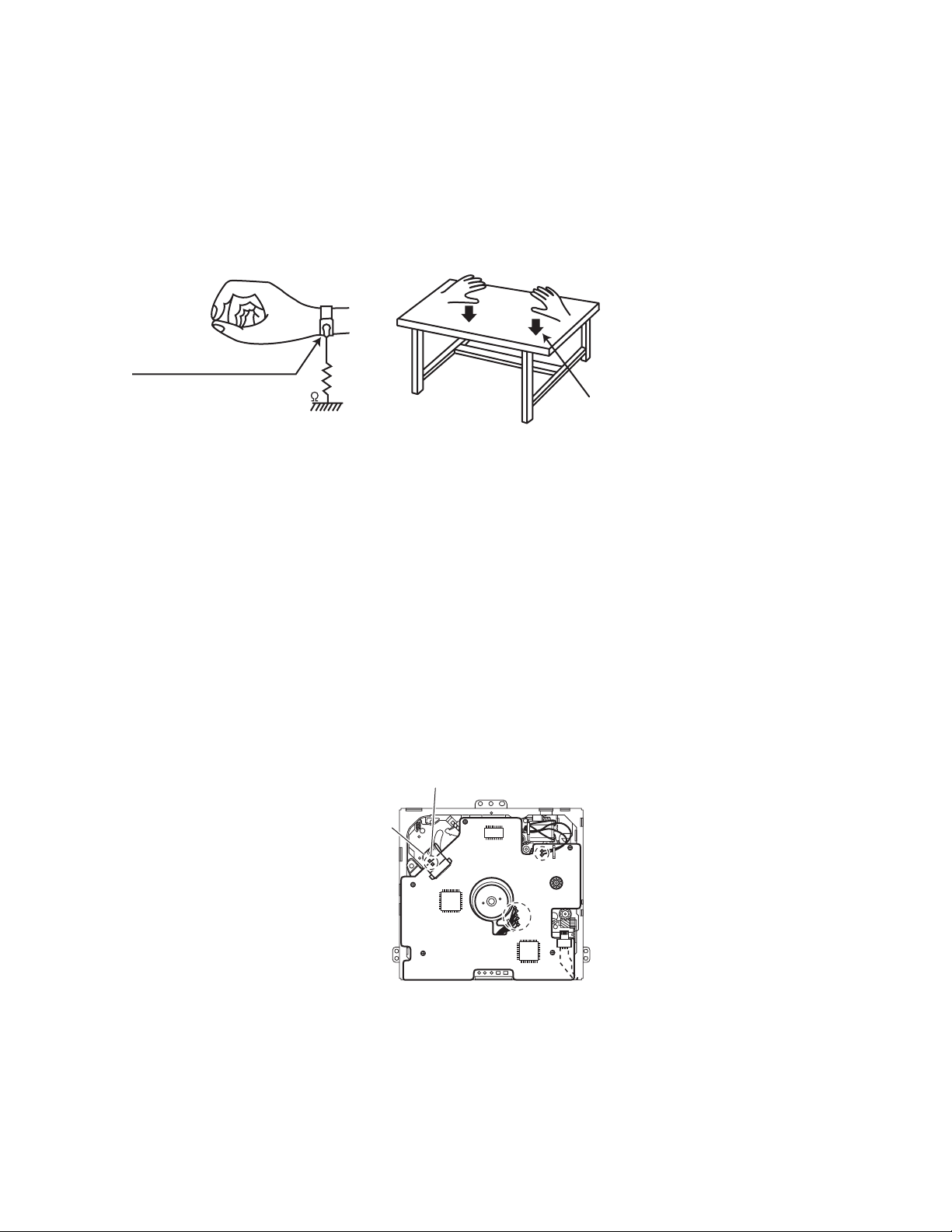
1.2.1 Grounding to prevent damage by static electricity
Static electricity in the work area can destroy the optical pickup (laser diode) in devices such as CD players.
Be careful to use proper grounding in the area where repairs are being performed.
(1) Ground the workbench
Ground the workbench by laying conductive material (such as a conductive sheet) or an iron plate over it before placing the
traverse unit (optical pickup) on it.
(2) Ground yourself
Use an anti-static wrist strap to release any static electricity built up in your body.
(caption)
Anti-static wrist strap
1M
Conductive material
(conductive sheet) or iron plate
(3) Handling the optical pickup
• In order to maintain quality during transport and before installation, both sides of the laser diode on the replacement optical
pickup are shorted. After replacement, return the shorted parts to their original condition.
(Refer to the text.)
• Do not use a tester to check the condition of the laser diode in the optical pickup. The tester's internal power source can easily
destroy the laser diode.
1.3 Handling the traverse unit (optical pickup)
(1) Do not subject the traverse unit (optical pickup) to strong shocks, as it is a sensitive, complex unit.
(2) Cut off the shorted part of the flexible cable using nippers, etc. after replacing the optical pickup. For specific details, refer to the
replacement procedure in the text. Remove the anti-static pin when replacing the traverse unit. Be careful not to take too long a
time when attaching it to the connector.
(3) Handle the flexible cable carefully as it may break when subjected to strong force.
(4) It is not possible to adjust the semi-fixed resistor that adjusts the laser power. Do not turn it.
1.4 Attention when traverse unit is decomposed
*Please refer to "Disassembly method" in the text for the CD pickup unit.
• Apply solder to the short land before the flexible wire is disconnected from the connector on the CD pickup unit.
(If the flexible wire is disconnected without applying solder, the CD pickup may be destroyed by static electricity.)
• In the assembly, be sure to remove solder from the short land after connecting the flexible wire.
Short-circuit point
Flexible wire
1-4 (No.MA047)
Page 5
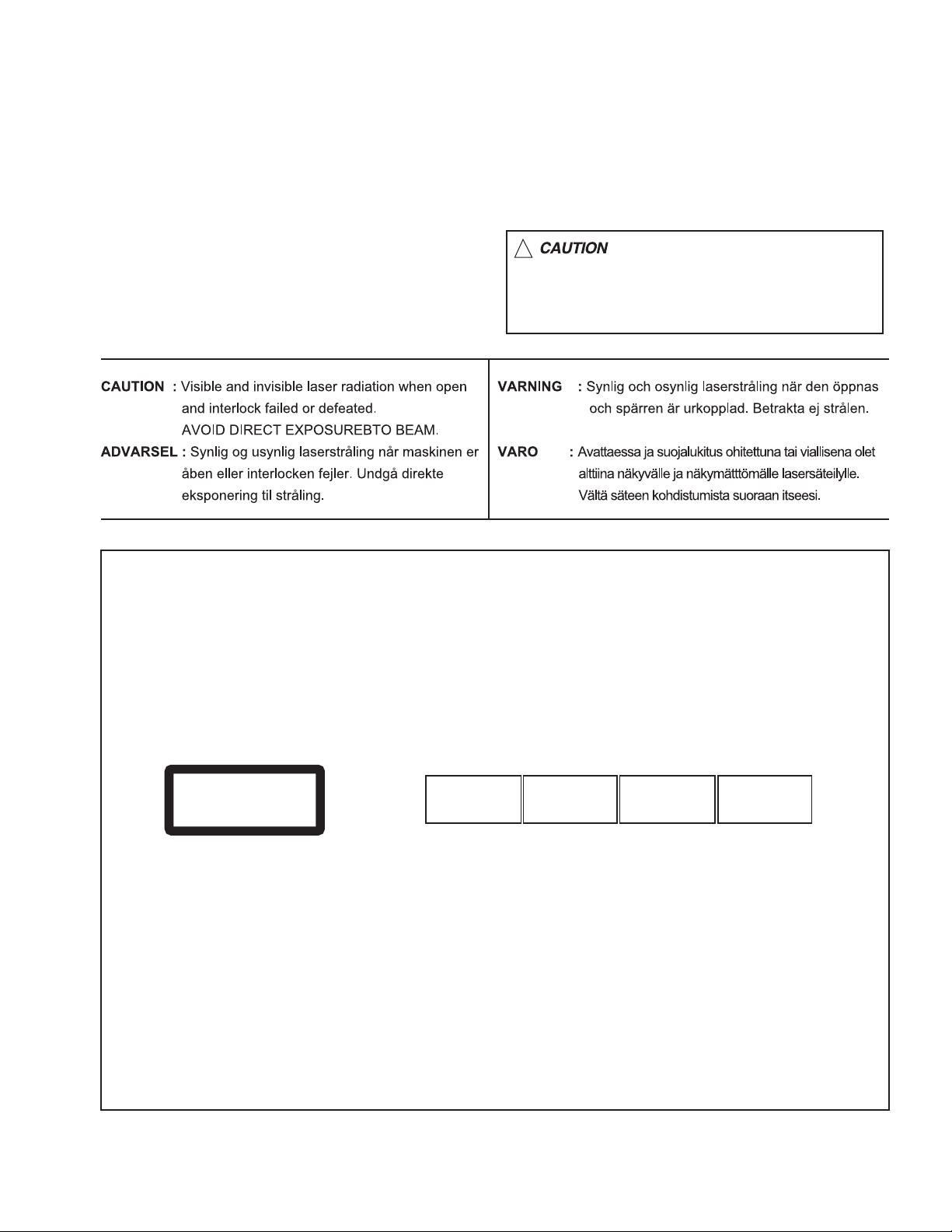
1.5 Important for laser products
!
1.CLASS 1 LASER PRODUCT
2.DANGER : Invisible laser radiation when open and inter
lock failed or defeated. Avoid direct exposure to beam.
3.CAUTION : There are no serviceable parts inside the
Laser Unit. Do not disassemble the Laser Unit. Replace
the complete Laser Unit if it malfunctions.
4.CAUTION : The CD,MD and DVD player uses invisible
laser radiation and is equipped with safety switches which
prevent emission of radiation when the drawer is open and
the safety interlocks have failed or are defeated. It is
dangerous to defeat the safety switches.
5.CAUTION : If safety switches malfunction, the laser is able
to function.
6.CAUTION : Use of controls, adjustments or performance of
procedures other than those specified here in may result in
hazardous radiation exposure.
Please use enough caution not to
see the beam directly or touch it
in case of an adjustment or operation
check.
REPRODUCTION AND POSITION OF LABELS
WARNING LABEL
CAUTION : Visible and Invisible
CLASS 1
LASER PRODUCT
laser radiation when open and
interlock failed or defeated.
AVOID DIRECT EXPOSURE TO
BEAM. (e)
ADVARSEL : Synlig og usynlig
laserstråling når maskinen er
åben eller interlocken fejeler.
Undgå direkte eksponering til
stråling. (d)
VARNING : Synlig och
osynling laserstrålning när
den öppnas och spärren är
urkopplad. Betrakta ej
strålen. (s)
VARO : Avattaessa ja suojalukitus
ohitettuna tai viallisena olet alttiina
näkyvälle ja näkymättömälle
lasersäteilylle. Vältä säteen
kohdistumista suoraan itseesi. (f)
(No.MA047)1-5
Page 6

SECTION 2
SPECIFIC SERVICE INSTRUCTIONS
This service manual does not describe SPECIFIC SERVICE INSTRUCTIONS.
1-6 (No.MA047)
Page 7
SECTION 3
DISASSEMBLY
3.1 Main body section
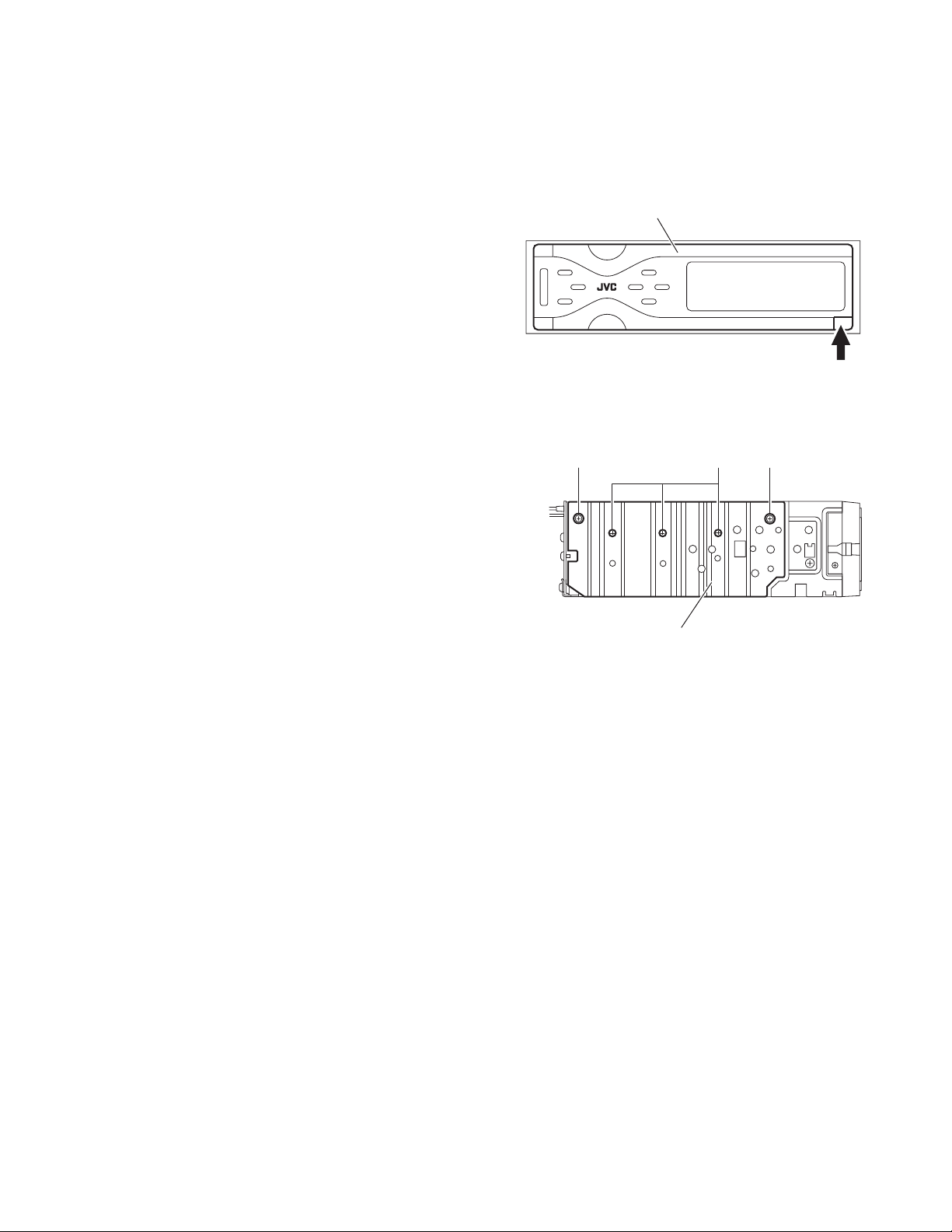
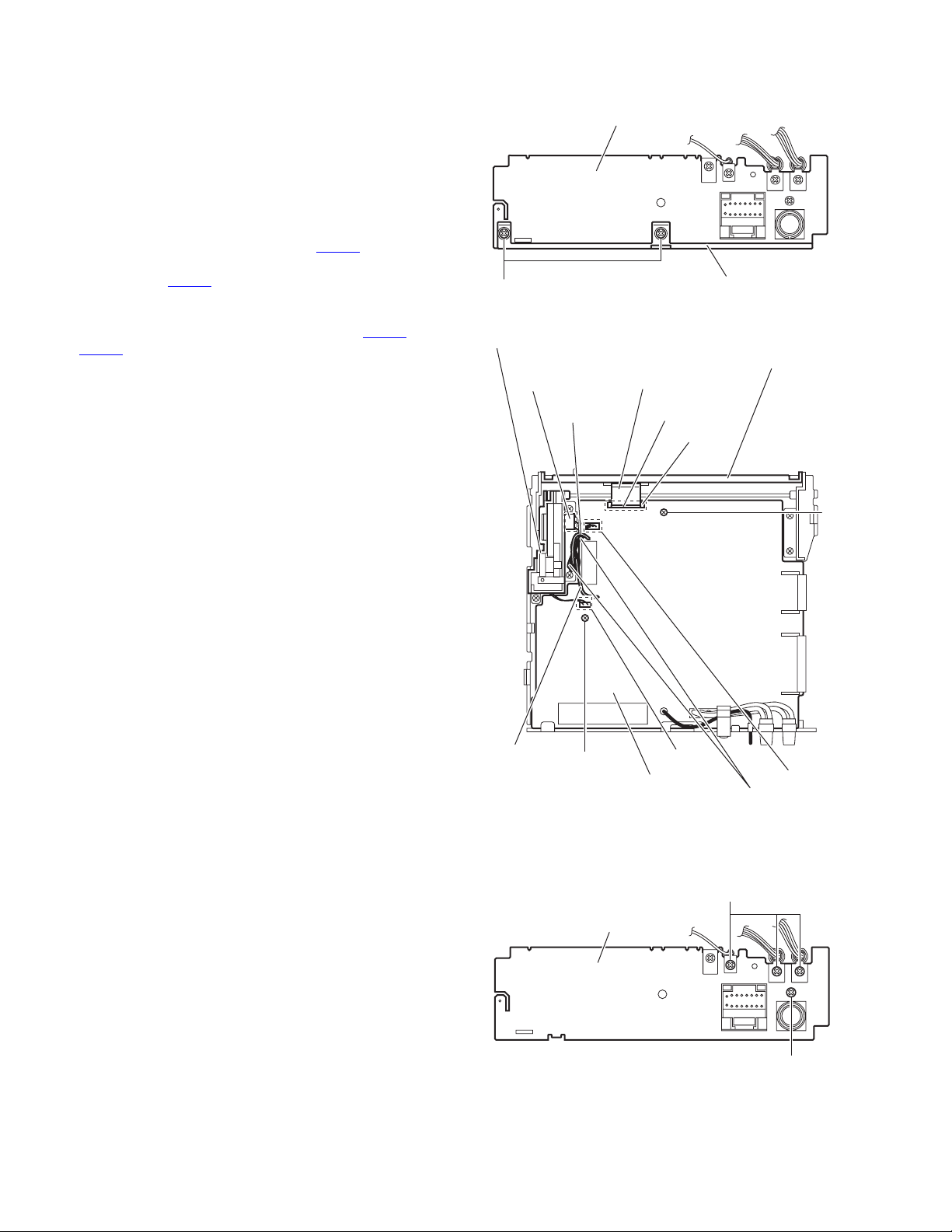
3.1.1 Removing the front panel assembly
(See Fig.1)
(1) Push the detach button in the lower right part of the front
panel assembly.
(2) Remove the front panel assembly.
3.1.2 Removing the heat sink
(See Fig.2)
(1) From the left side of the main body, remove the two screws
A and three screws B attaching the heat sink.
Front panel assembly
Detach button
Fig.1
AAB
Heat sink
Fig.2
(No.MA047)1-7
Page 8
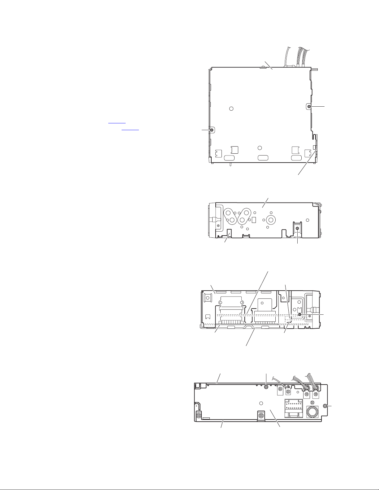
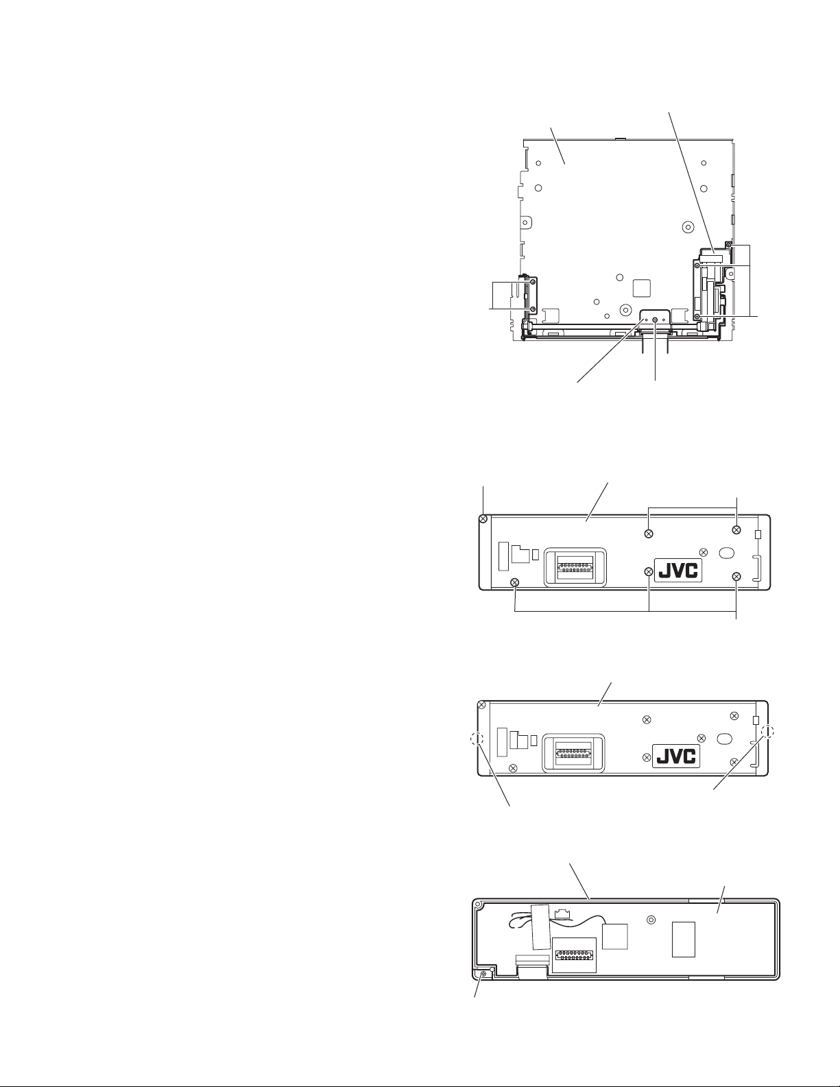
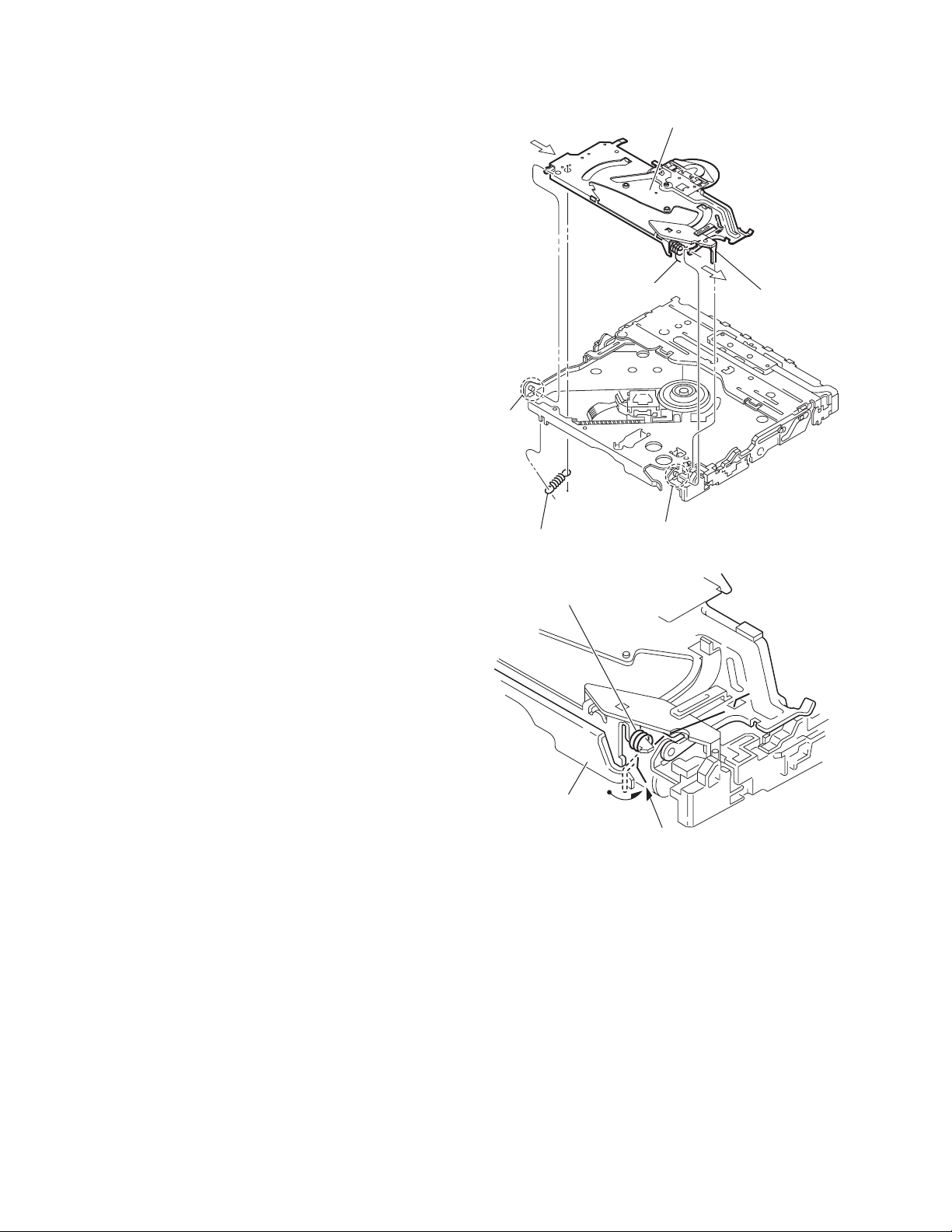
3.1.3 Removing the top chassis assembly
(See Figs.3 to 6)
• Prior to performing the following procedures, remove the heat
sink.
Reference:
Remove the front panel assembly as required.
(1) From the bottom side of the main body, remove the two
screws C attaching the top chassis assembly to the bottom
chassis assembly. (See Fig.3)
(2) From the both and rear sides of the main body, remove the
four screws D attaching the top chassis assembly to the
bottom chassis assembly. (See Figs.4 to 6)
(3) Lift the top chassis assembly in the direction of the arrow,
and disconnect the connector CN501
control board from the connector CN702 on the main
board. (See Figs.5 and 6)
(4) Take out the top chassis assembly from the bottom chassis
assembly.
on the mechanism
Bottom chassis assembly
C
C
Top chassis assembly
Fig.3
Top chassis assembly
Bottom chassis assembly
Mechanism control board
Top chassis assembly
Main board
Bottom chassis assembly
Top chassis assembly
D
Fig.4
CN501
D
CN702
Fig.5
D
D
1-8 (No.MA047)
Bottom chassis assembly
Rear bracket
Fig.6
Page 9
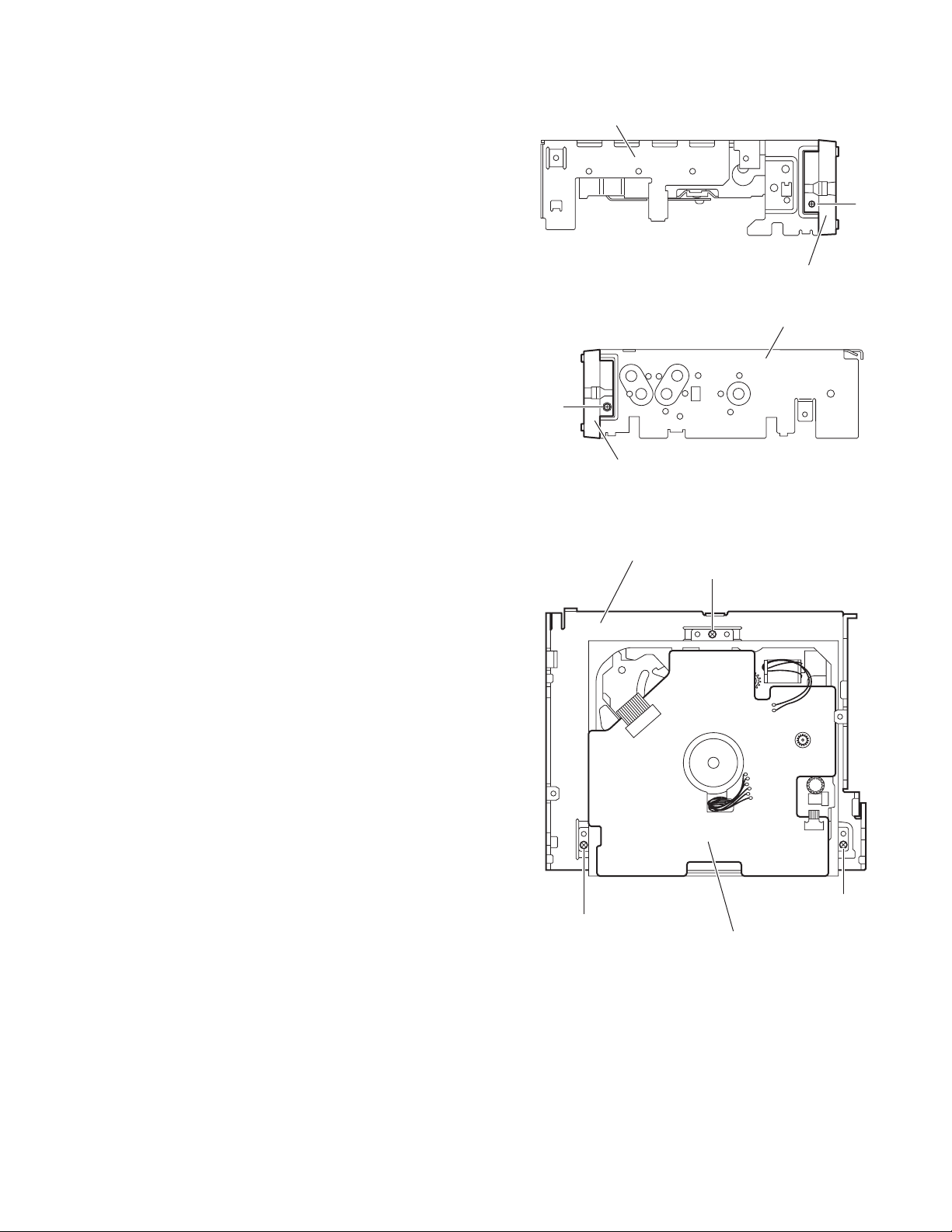
3.1.4 Removing the front chassis
(See Figs.7 and 8)
• Prior to performing the following procedure, remove the front
panel assembly, heat sink and top chassis assembly.
(1) From the both sides of the top chassis assembly, remove
the two screws E attaching the front chassis.
3.1.5 Removing the CD mechanism assembly
(See Fig.9)
• Prior to performing the following procedures, remove the front
panel assembly, heat sink and top chassis assembly.
(1) From the inside of the top chassis assembly, remove the
three screws F attaching the CD mechanism assembly.
(2) Take out the CD mechanism assembly from the top chas-
sis.
Top chassis assembly
E
Front chassis
Fig.7
Top chassis assembly
E
Front chassis
Fig.8
Top chassis
F
F
F
CD mechanism assembly
Fig.9
(No.MA047)1-9
Page 10
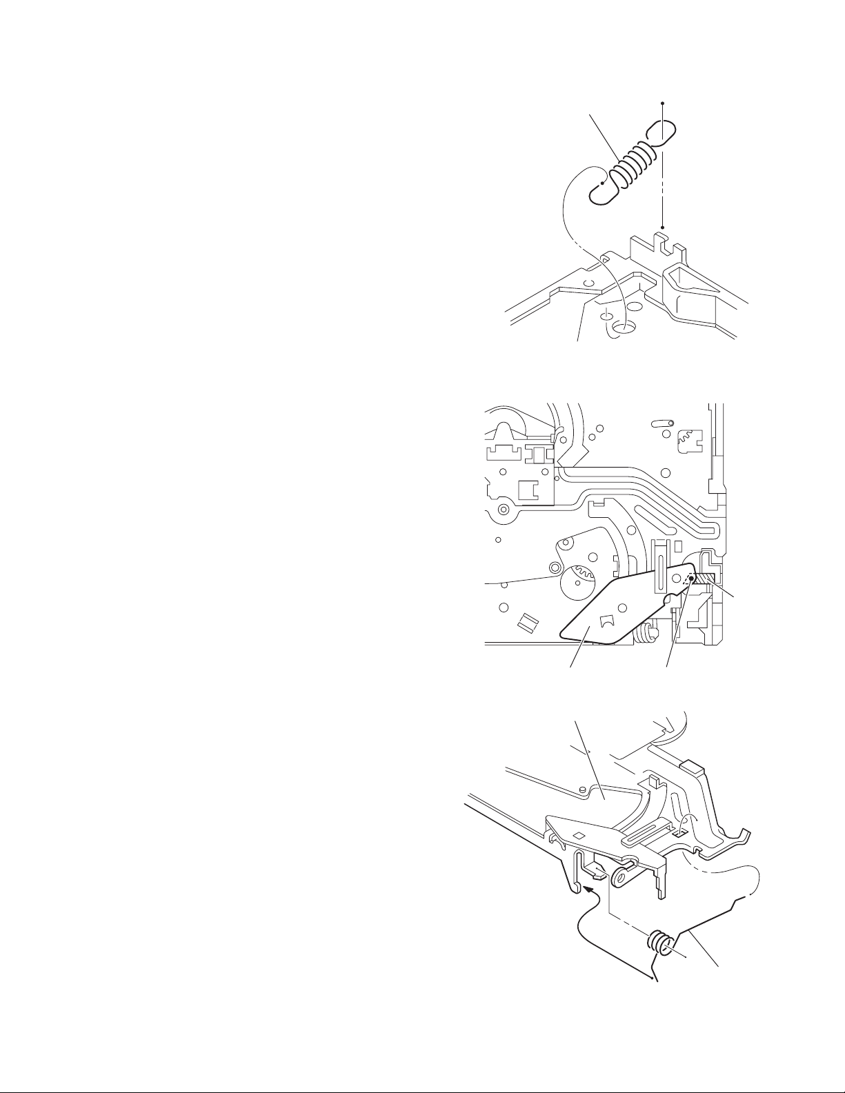
3.1.6 Removing the main board
(See Figs.10 and 11)
• Prior to performing the following procedures, remove the front
panel assembly, heat sink and top chassis assembly.
(1) From the rear side of the bottom chassis assembly, remove
the two screws G attaching the rear bracket to the bottom
chassis assembly. (See Fig.10)
(2) From the top side of the bottom chassis assembly, remove
the two screws H attaching the main board to the bottom
chassis assembly. (See Fig.11)
(3) Release the stopper of the connector CN701
board in an upward direction, disconnect the card wire from
the connector CN701
(4) Disconnect the wire from the connector of the front door
mechanism assembly. (See Fig.11)
(5) Disconnect the wire from the connectors CN991
CN992 on the main board. (See Fig.11)
Reference:
After connecting the wires, fix the wires with the wire
holders.
(6) Take out the main board from the bottom chassis assem-
bly.
. (See Fig.11)
on the main
and
Rear bracket
G
Front door mechanism assembly
Connector
Wire holder
Card wire
Bottom chassis assembly
Fig.10
CN701
Stopper
Bottom chassis assembly
H
3.1.7 Removing the rear bracket
(See Fig.12)
• Prior to performing the following procedures, remove the front
panel assembly, heat sink, top chassis assembly and main
board.
(1) From the rear side of the main board, remove the wires
from the rear bracket in the direction of the arrow.
(2) Remove the four screws J attaching the rear bracket to the
main board.
Reference:
After attaching the rear bracket to the main board, pass the
wires through the wire holder and insert them into the slots of
the rear bracket.
1-10 (No.MA047)
Wire holder
H
Main board
Rear bracket
CN991
CN992
Wires
Fig.11
J
J
Fig.12
Page 11
3.1.8 Removing the front door mechanism assembly
(See Fig.13)
• Prior to performing the following procedures, remove the front
panel assembly, heat sink, top chassis assembly and main
board.
(1) From the top side of the bottom chassis assembly, remove
the screw K attaching the shaft holder to the bottom chassis.
(2) Remove the five screws L attaching the front door mecha-
nism assembly to the bottom chassis.
Reference:
When attaching the screws M and N, apply a locking
agent them.
(3) Take out the front door mechanism assembly from the bot-
tom chassis.
Front door mechanism assembly
Bottom chassis
3.1.9 Removing the front board
(See Figs.14 to 16)
• Prior to performing the following procedures, remove the front
panel assembly.
(1) From the rear side of the front panel assembly, remove the
six screws M attaching the rear cover assembly to the front
panel assembly. (See Fig.14)
(2) Release the twelve joints a of the front panel assembly and
remove the rear cover assembly. (See Fig.15)
(3) Take out the front board from the front panel assembly.
(See Fig.16)
Caution:
Take care not to lose the spring.
L
M
Shaft holder
Rear cover assembly
Rear cover assembly
L
K
Fig.13
M
M
Fig.14
Joints a
Front panel assembly
Spring
Joints a
Fig.15
Front board
Fig.16
(No.MA047)1-11
Page 12
3.2 CD mechanism assembly
• Prior to performing the following procedure "Removing the CD mechanism assembly".
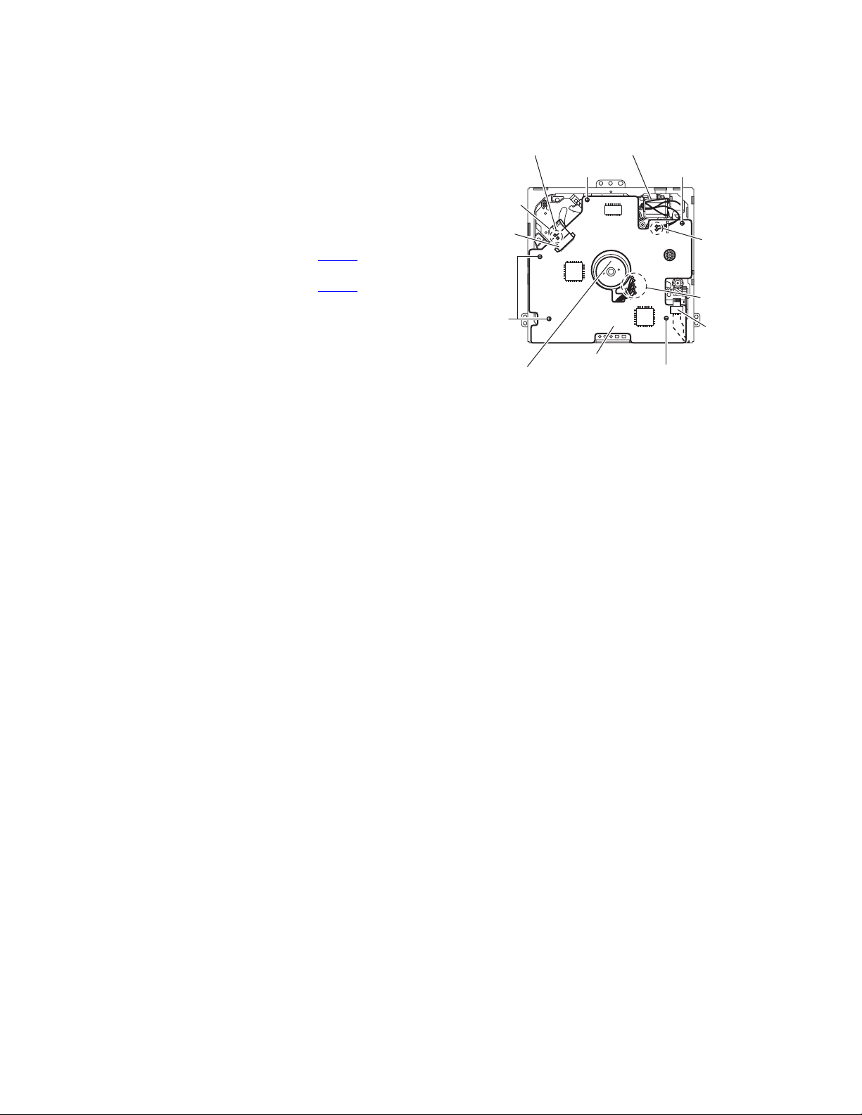
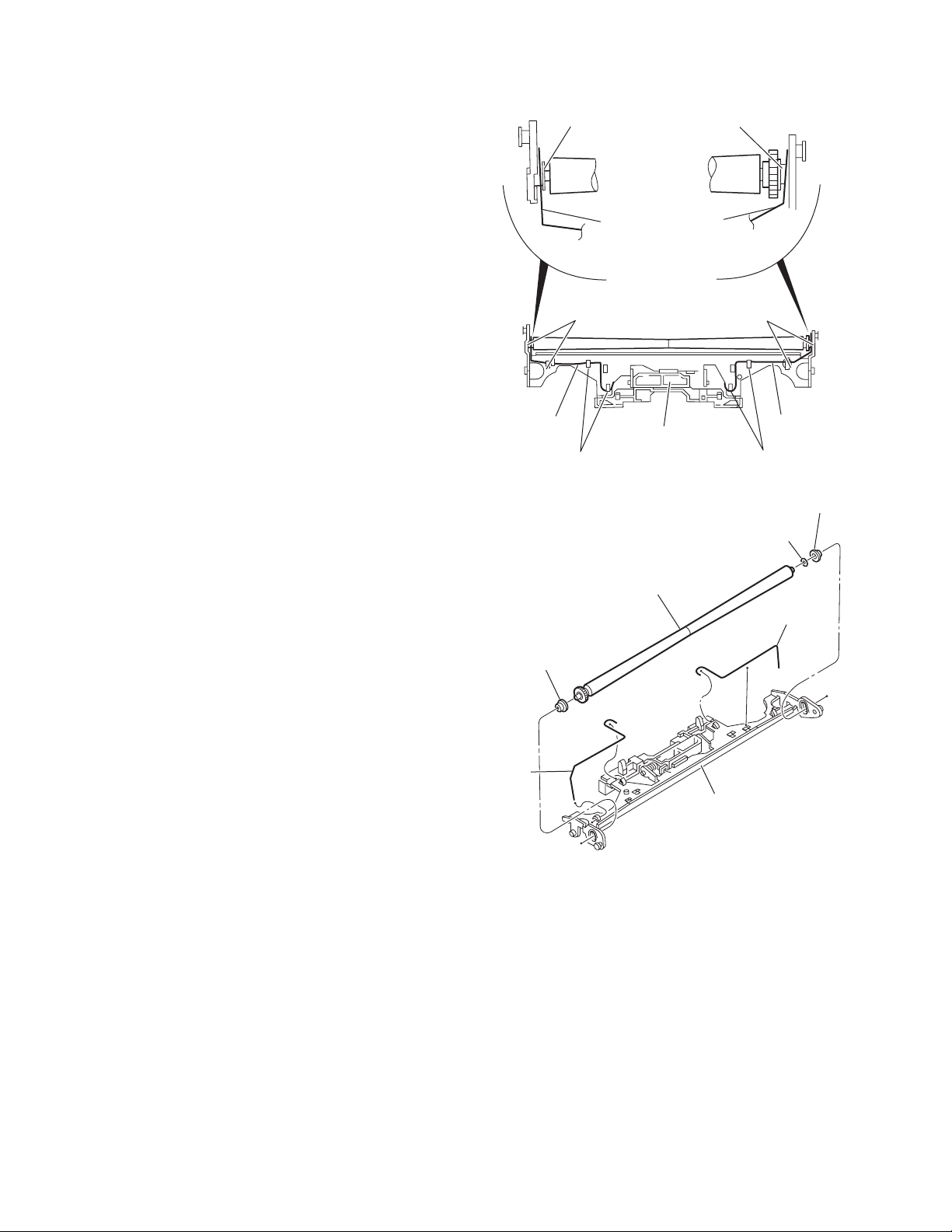
3.2.1 Removing the front-end board
(See Fig.1)
(1) From the top side of the CD mechanism assembly, solder
the short-circuit point on the flexible wire extending from
the CD pickup.
Caution:
Solder the short-circuit points on the flexible wire extending from the DVD pickup. If you do not follow this instruction, the DVD pickup may be damaged.
(2) Disconnect the flexible wire from connector CN601
front-end board.
(3) Disconnect the flexible wire from connector CN503
front-end board.
(4) Remove the solders from two solder points a on the front-
end board and disconnect the wire extending from the feed
motor.
(5) Remove the solders from six solder points b on the front-
end board disconnect the wires extending from the spindle
motor, SW board and reset SW board.
(6) Remove the five screws A attaching the front-end board.
Caution:
Unsolder the solders from the short-circuit points after reassembling.
on the
on the
Short-circuit point
Flexible wire
CN601
A
Spindle motor
Feed motor
A
Front end board
Fig.1
A
Solder
point a
Solder
point b
CN503
A
1-12 (No.MA047)
Page 13
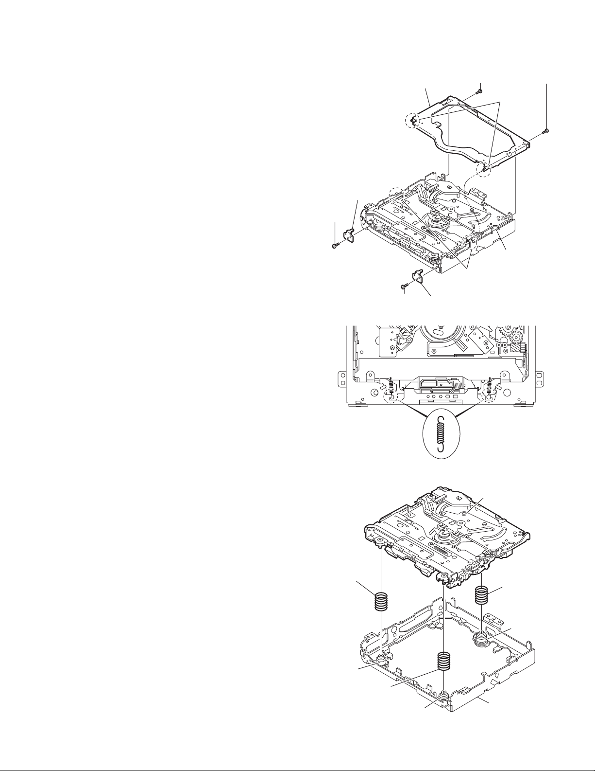
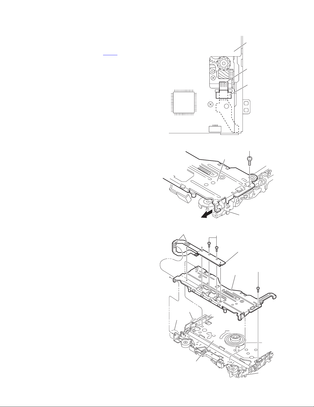
3.2.2 Removing the top cover
(See Fig.2)
(1) From the back side of the CD mechanism assembly, re-
move the two screws B attaching the top cover.
(2) Take out the top cover upward.
Reference:
When reassembling the top cover, set parts c of the top cover
under the bending parts d of the chassis base.
3.2.3 Removing the mechanism section
(See Figs.2 to 4)
• Prior to performing the following procedure, remove the top
cover.
(1) From the front side of the CD mechanism assembly, re-
move the two screws C attaching the right and left stoppers. (See Fig.2)
(2) Remove the two floating springs on the bottom of the body.
(See Fig.3)
(3) Take out the mechanism section upward, and remove the
three damper springs from the dampers. (See Fig.4)
Caution:
• When reassembling the mechanism section, reattach the
damper spring to the damper respectively and insert the
three shafts on the bottom of the mechanism to the dampers. (See Fig.4)
• Before inserting the shaft to the dampers, apply IPA to the
hole of damper.
C
Stopper
Top cover
Stopper
C
Fig.2
B
Parts c
B
Parts d
Chassis base
Damper
spring(F)
(Silver)
Damper
(Black)
Damper
spring(F)
(Silver)
Floating spring
Damper
(Black)
Fig.3
Mechanism section
Damper
spring(R)
(Red)
Damper
(Purple)
Chassis base
Fig.4
(No.MA047)1-13
Page 14
3.2.4 Removing the clamper unit
(See Figs.5 and 6)
• Prior to performing the following procedures, remove the top
cover and mechanism section.
(1) From the bottom of the mechanism section, remove the
clamper spring2. (See Fig.5)
(2) Release part e of the clamper spring from the bending part
of the chassis base assembly. (See Fig.6)
(3) Move the clamper unit in the direction of the arrow, and re-
lease the two joints f and g. (See Fig.5)
(4) Take out the clamper unit upward. (See Fig.5)
Clamper unit
Joint f
Clamper2 spring
Clamper spring
Clamper spring
Joint g
Fig.5
Part h
1-14 (No.MA047)
Chassis base
Part e
Fig.6
Page 15
3.2.5 Reattaching the clamper unit
(See Figs.5 to 9)
(1) From the bottom of the mechanism section, attach the
clamper spring2 to the clamper unit. (See Figs.5 and 7)
(2) Move the clamper unit to set the side joints f and g to each
boss of the chassis base. (See Fig.5)
(3) Make sure that part h is inserted to the notch of the chassis
base. (See Figs.5 and 8)
(4) Move the clamper spring to the outside of the bending part
of the chassis base. (See Fig.9)
Caution:
When reattaching the clamper unit, temporarily hook the end
of the clamper spring as shown in the figure to make the work
easy. (See Fig.9)
Clamper2 spring
Chassis base
Fig.7
Clamper unit
Clamper unit
Notch
Part h
Fig.8
Clamper spring
Fig.9
(No.MA047)1-15
Page 16
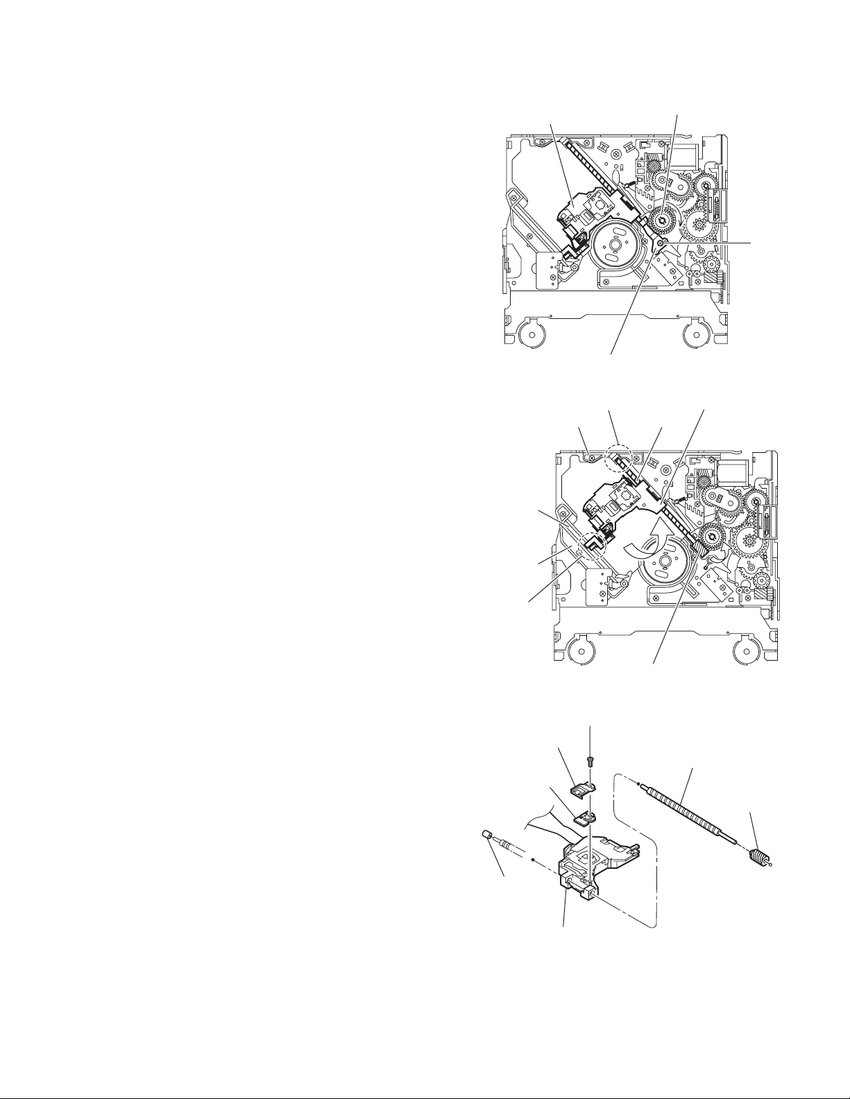
3.2.6 Removing the front unit
(See 10 to 12)
• Prior to performing the following procedures, remove the top
cover and mechanism section.
(1) From the bottom side of the mechanism section, discon-
nect the flexible wire from connector CN503
end board. (See Fig.10)
(2) From the top of the mechanism section, remove the screw
D attaching the front unit. (See Fig.11)
(3) Move the front unit toward the front to release joint i. (See
Fig.11)
(4) Release two joints j and k on the right side of the chassis
base. (See Fig.12)
(5) Take out the front unit upward, and remove the two screws
E attaching the switch wire. (See Fig.12)
Reference:
You can remove the switch wire only without removing the
front unit.
Caution:
When reassembling, attach the flexible wire extending from
the switch wire using a double-stick tape. (See Fig.12)
on the front-
Front-end
board
Flexible
wire
CN503
Fig.10
D
Front unit
Double-stick tape
Joint j
Joint k
Chassis base
Fig.11
E
Fig.12
Joint i
Switch wire
Front unit
D
Joint i
1-16 (No.MA047)
Page 17
3.2.7 Removing the loading arm S.A.
(See Figs.13 and 14)
• Prior to performing the following procedures, remove the top
cover, mechanism section and front unit.
(1) From top side of the front unit, move the loading arm S.A.
from the front upwards. (See Fig.13)
(2) Release the bosses from the right and left joints m and n of
the chassis base. (See Figs.13 and 14)
(3) Release the boss from notch p of the connect arm on the
right side of the body, and release the boss from notch q of
the slide cam assembly on the left side. (See Fig.14)
Joint n
Side cam
assembly
Notch q
Joint n
Loading arm S.A.
Joint m
Fig.13
Loading arm S.A.
Joint m
Notch p
Fig.14
Notch p
Connect arm
(No.MA047)1-17
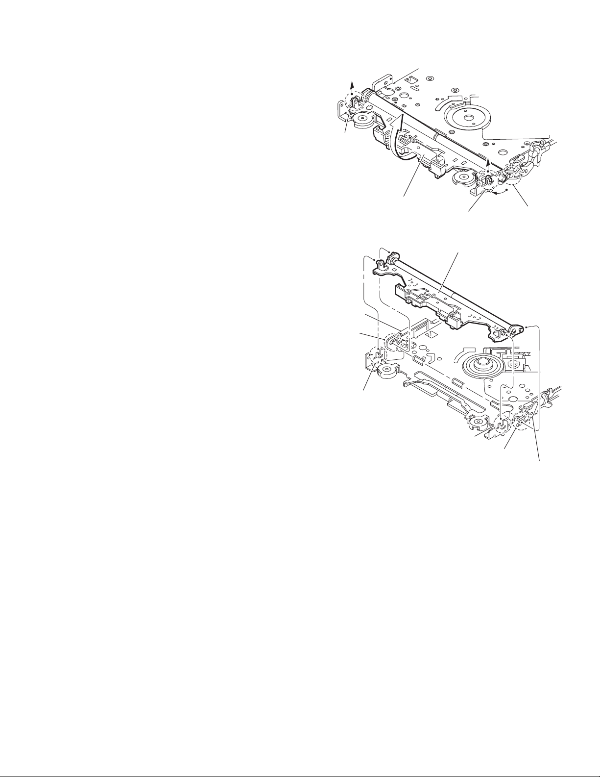
Page 18
3.2.8 Removing the rod (L)(R) and roller assembly
(See Figs.15 and 16)
• Prior to performing the following procedures, remove the top
cover, mechanism section, front unit and loading arm S.A.
(1) From the bottom side of the loading arm S.A., release the
rod (L) and (R) from the joints r. (See Fig.15)
(2) Remove the roller assembly from the loading assembly.
(See Fig.16)
(3) Remove the two collars and washer from the roller assem-
bly. (See Fig.16)
Caution:
After attaching the roller assembly to the loading arm S.A., attach the rod (L) and (R). Attach the rods to the right and left collars of the roller. (See Fig.15)
Collar
Joints r
Collar
Rod(R) Rod(L)
Joints r
Rod(L)
Rod(R)
Collar
Joints r
Loading arm S.A.
Rod(L)
Joints r
Fig.15
Collar
Washer
Roller assembly
Rod(R)
Loading arm S.A.
Fig.16
1-18 (No.MA047)
Page 19
3.2.9 Removing the CD pickup assembly
r
(See Figs.17 to 19)
• Prior to performing the following procedure, remove the front-
end board.
(1) From the bottom of the CD mechanism assembly, turn the
feed gear in the direction of the arrow to move the CD pickup assembly outwards. (See Fig.17)
(2) Remove the screw F attaching the thrust spring. (See
Fig.17)
(3) Remove the CD pickup assembly upward from the side of
L.S.gear and release sub shaft from joint s. (See Fig.18)
(4) Move the lead screw of the CD pickup assembly in the di-
rection of the arrow to release at joint t. (See Fig.18)
(5) Remove the screw G attaching the rack spring and rack
plate on the CD pickup. (See Fig.19)
(6) Pull out the lead screw. (See Fig.19)
Caution:
• When reattaching the CD pickup assembly, reattach the sub
shaft at section s of the CD pickup assembly to the sub guide
first, and attach the lead screw shaft to the joint t on the
L.S.holder2. (See Fig.18)
• Perform adjustment after replacing the pickup.
CD Pickup assembly
Thrust spring
Joint t
L.S.holder 2
Feed gear
F
Fig.17
CD Pickup assembly
Lead screw
Sub shaft
Sub guide
Joint s
Rack spring
Rack plate
L.S.Collar
L.S.Gear
Fig.18
G
Lead screw
L.S.Gea
CD Pickup
Fig.19
(No.MA047)1-19
Page 20
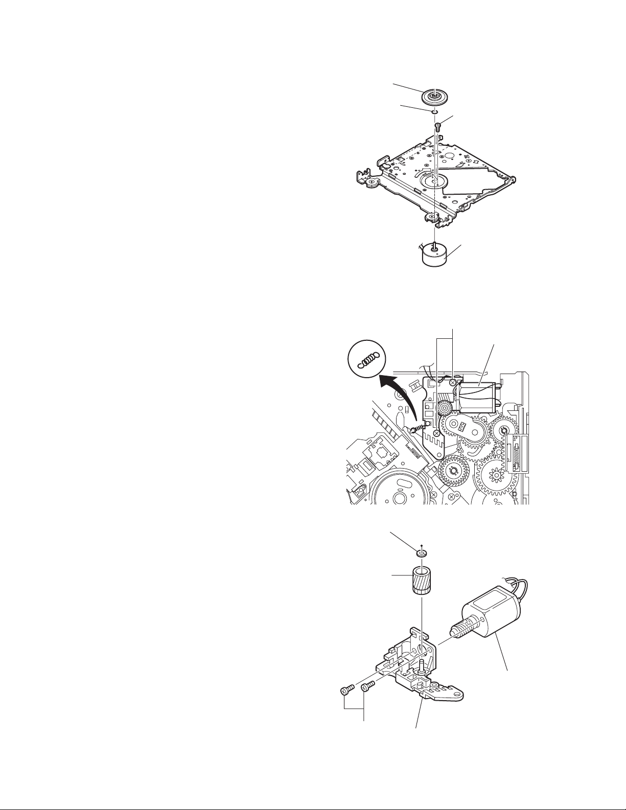
3.2.10 Removing the spindle motor
r
(See Fig.20)
• Prior to performing the following procedure, remove the frontend board.
(1) From the bottom side of the CD mechanism assembly, re-
move the T.table assembly and washer from the spindle
motor.
(2) Remove the two screws H attaching the spindle motor.
Caution:
Perform adjustment when reattaching the spindle motor.
3.2.11 Removing the FL motor S.A.
(See Figs.21 and 22)
• Prior to performing the following procedure, remove the frontend board.
(1) From the top side of the CD mechanism assembly, remove
the F.T.spring. (See Fig.21)
(2) Remove the two screws J attaching the FL motor S.A. (See
Fig.21)
(3) Remove the slit washer from the motor H.assembly and
pull out the worm wheel. (See Fig.22)
(4) Remove the two screws K attaching the FL motor. (See
Fig.22)
T. table assembly
Washer
F.T.Spring
H
Spindle motor
Fig.20
J
FL Motor S.A.
1-20 (No.MA047)
Fig.21
Slit washer
Worm wheel
FL Moto
K
Motor H.assembly
Fig.22
Page 21
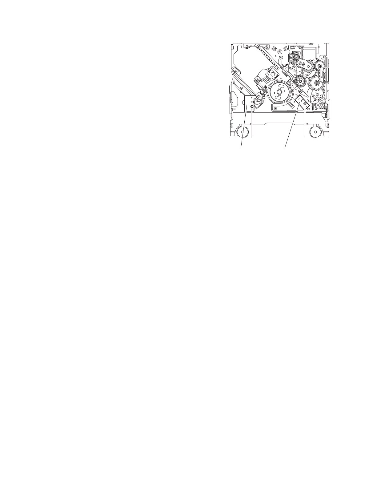
3.2.12 Removing the SW board and reset SW board
(See Fig.23)
• Prior to performing the following procedure, remove the front-
end board.
(1) From the top side of the CD mechanism assembly, remove
the screw L attaching the SW board.
(2) Remove the screw M attaching the reset SW board.
ML
Reset SW boardSW board
Fig.23
(No.MA047)1-21
Page 22

SECTION 4
ADJUSTMENT
4.1 Adjustment method
Test instruments required for adjustment
(1) Digital oscilloscope (100MHz)
(2) Electric voltmeter
(3) Digital tester
(4) Tracking offset meter
(5) Test Disc JVC :CTS-1000
(6) Extension cable for check
EXTSH002-22P × 1
Standard volume position
Balance and Bass &Treble volume : lndication"0"
Loudness : OFF
How to connect the extension cable for adjusting
Caution:
Be sure to attach the heat sink and rear bracket onto the power amplifier IC and regulator IC respectively, before supply the power.
If voltage is applied without attaching these parts, the power amplifier IC and regulator IC will be destroyed by heat.
Standard measuring conditions
Power supply voltage DC14.4V(11 to 16V)
Load impedance 20KΩ(2 Speakers connection)
Output Level
KD-AR7000
KD-SHX700
Dummy load
Exclusive dummy load should be used for AM,and FM. For FM
dummy load,there is a loss of 6dB between SSG output and
antenna input.The loss of 6dB need not be considered since
direct reading of figures are applied in this working standard.
Line out 5.0V (Vol. MAX)
Line out 4.0V (Vol. MAX)
Extension cable: EXTSH002-22P
Heat sink
Rear bracket
1-22 (No.MA047)
Page 23

4.2 Service mode
4.2.1 Service mode setting
(1) Push POWER BOTTON (Power ON)
(2) Set to service mode
By pushing and holding "DISP" button + "VOLUME +" button + "MENU" button sequentially.
"SOURCE" button
"OK" button
PICT
BACK
DISP
OK
BAND
"CURSOR" button
SOURCE
MENU
SERVICE MODE (MENU)
SERVICE MODE
RUNNING MODE
DATA CLEAR
ROM COLLECTION
DSP TUNER S MODE
DSP TUNER ADJUST
SERVICE MODE
VERSION
ERR READ
CD DATA READ
"DISP" button "MENU" button
"VOLUME +" button
VERSION
VERSION
MAIN V***
CH V***
CD ERROR READ
CD ERROR READ
CH ERROR READ
PANEL MECHA ERROR READ
A.DSP ERROR READ
T.DSP ERROR READ
CD V***
CD ERROR READ
TOTAL ERROR : ****
E1 **** E3 ****
E2 ****
1 **** 4****
2 **** 5****
3 ****
CH ERROR READ
TOTAL ERROR : ****
E1 **** E3 ****
E2 ****
1 **** 4****
2 **** 5****
3 ****
PANEL MECHA ERROR READ
TOTAL ERROR : ****
E1 **** E3 ****
E2 ****
1 **** 4****
2 **** 5****
3 ****
A.DSP ERROR READ
ERROR COUNT ***
RETRY OVER ***
T.DSP ERROR READ
RETRY ***
AB
NG ***
(No.MA047)1-23
Page 24

AB
f
f
CD DATA READ
ADJ NOW
ADJ INT
OTHERS
RUNNING MODE
RUNNING MODE 1
RUNNING MODE 2
RUNNING MODE 3
RUNNING MODE 4
RUNNING MODE 1
COUNT : ******
ERROR : ******
RUNNING MODE 2
COUNT : ******
ERROR : ******
RUNNING MODE 3
COUNT : ******
ERROR : ******
RUNNING MODE 4
COUNT : ******
ERROR : ******
ADJ NOW
FEB ** FEO ** TEB ** RFG**
FGA ** TEO ** TGA **
ADJ INT
FEB ** FEO ** TEB ** RFG**
FGA ** TEO ** TGA **
OTHERS
IOP TEMP I** T** TOP INT
TEMP MIX ** P TOTAL ****H
Running mode1
Loading TOC reading 1st Tr playing (30s)
Last Tr playing (30s) Eject
Running mode1
Loading TOC reading 1st Tr playing (30s)
Last Tr playing (30s) Eject
Running mode3
Loading Check completed Eject
Running mode 4
Loading TOC reading Last Tr playing (1s)
Eject
ADJ NOW
The auto adjustment value o
survo at now
ADJ INT
The auto adjustment value o
survo at initial
DATA CLEAR
EPROM CLEAR
NAME CLEAR
CD ERROR CLEAR
CH ERROR CLEAR
PANEL MECHA ERROR CLEAR
PICTURE CLEAR
A.DSP ERROR CLEAR
T.DP ERROR CLEAR
EPROM CLEAR
NOW...
NAME CLEAR
NOW...
CD ERROR CLEAR
NOW...
CH ERROR CLEAR
NOW...
PANEL MECHA ERROR CLEAR
NOW...
EPROM CLEAR
NAME CLEAR
CD ERROR CLEAR
CH ERROR CLEAR
PANEL MECHA ERROR CLEAR
CD
1-24 (No.MA047)
Page 25
CD
PICTURE CLEAR
NOW...
PICTURE CLEAR
A.DSP ERROR CLEAR
NOW...
A.DSP ERROR CLEAR
T.DSP ERROR CLEAR
NOW...
T.DSP ERROR CLEAR
ROM COLLECTION
DATA READ
DATA CLEAR
DSP TUNER S MODE
VER=V*** SPI=**
PI=**** ***.** SMI=***%
PTY=** ******* MP=***%
TP/TA=*/* EON ADJ=***%
MS/DI=*/* STERO BW=*
AF
** ** ** ** ** ** **
** ** ** ** ** ** **
** ** ** **
RDS ENGINNER MODE
DATA READ (Without disk)
PLEASE INSERT
DATA CD
A panel is opened automatically
Insert data disk
DATA READ (With disk)
NOW...
DATA READING
DON'T TOUCH ANY KEY
DATA CLEAR
NOW...
Status "PI", "PTY", "TP/TA",
"EON", "MS/DI", "AF" are
RDS model only.
DATA CLEAR
If "DISP" and "SOURCE" buttons are pushed and
held during the usual display, it will shift to ROM
COLLECTION.
SUCCESS
SUCCESS!!
PLEASE EJECT CD
VER ***
FAILURE
FAIL
PLEASE EJECT CD
RDS model only
RDS ENGINNER MODE
OK/BAND : ENTER
SYNC=*
SYNC=*
DEFAULT * BACK / DISP
ENTER : OK / BAND
PIC=****s
PIC=****s
DEFAULT * BACK / DISP
ENTER : OK / BAND
AFC=****s
AFC=****s
EF
DEFAULT * BACK / DISP
ENTER : OK / BAND
SYNC=*
Select the value with
"CURSOR" button.
PIC=****s
Select the value with
"CURSOR" button.
AFC=****s
Select the value with
"CURSOR" button.
(No.MA047)1-25
Page 26

EF
SMTH1=******
SMTH1=******
SMTH2=******
SMTH2=******
MP=******
MP=******
ADJ=******
ADJ=******
SM L=******
SM L=******
SMM1=******
SMM1=******
SMM2=******
SMM2=******
DEFAULT * BACK / DISP
ENTER : OK / BAND
DEFAULT * BACK / DISP
ENTER : OK / BAND
DEFAULT * BACK / DISP
ENTER : OK / BAND
DEFAULT * BACK / DISP
ENTER : OK / BAND
DEFAULT * BACK / DISP
ENTER : OK / BAND
DEFAULT * BACK / DISP
ENTER : OK / BAND
DEFAULT * BACK / DISP
ENTER : OK / BAND
SMTH1=******
Change the value with
"CURSOR" button.
SMTH2=******
Change the value with
"CURSOR" button.
MP=******
Change the value with
"CURSOR" button.
ADJ=******
Change the value with
"CURSOR" button.
SM L=******
Change the value with
"CURSOR" button.
SMM1=******
Change the value with
"CURSOR" button.
SMM2=******
Change the value with
"CURSOR" button.
DSP TUNER AJUST
AUTO ADJUSTMENT
MANUAL ADJUSTMENT
RDS model only
AUTO ADJUSTMENT
AUTO ADJUSTMENT
1.FM DAA
87.5MHz
2.FM DAA
97.9MHz
3.FM DAA
108.0MHz
4.FM S.MATER
97.9MHz
40dBuV 0%
40dBuV 0%
40dBuV 0%
40dBuV 0%
1.FM DAA
87.5MHz
2.FM DAA
97.9MHz
3.FM DAA
108.0MHz
4.FM S.MATER
97.9MHz
40dBuV 0%
40dBuV 0%
40dBuV 0%
40dBuV 0%
High or Low or No Signal
No Signal
No Signal
No Signal
1-26 (No.MA047)
5.FM S.MATER
97.9MHz 7
6.FM FULL SEPARATION
97.9MHz 7
Lch 40MHzmod 1kHz
0dBuV 0%
0dBuV 0%
G H
5.FM S.MATER
97.9MHz 7
6.FM FULL SEPARATION
97.9MHz 7
0dBuV 0%
High or Low or No Signal
0dBuV 0%
Adjustment NG or No Signal
J
Page 27

G H
J
7.FM IF COUNTER
97.9MHz 7
8.AM S.METER
999kHz 26
9.AM S.METER
999kHz 56
10.AM IF COUNTER
999kHz 56
AUTO ADJUSTMENT
COMPLETED
0dBuV 0%
dBuV 0%
dBuV 0%
dBuV 0%
MANUAL ADJUSTMENT
MANUAL ADJUSTMENT
1.FM DAA
87.5MHz
2.FM DAA
97.9MHz
40dBuV 0%
40dBuV 0%
Press OK
Press OK
7.FM COUNTER
97.9MHz 7
8.AM S.METER
999kHz 26
9.AM S.METER
999kHz 56
10.AM IF COUNTER
999kHz 56
1.FM DAA
87.5MHz
2.FM DAA
97.9MHz
0dBuV 0%
Adjustment NG or No Signal
dBuV 0%
High or Low or No Signal
dBuV 0%
High or Low or No Signal
dBuV 0%
Adjustment NG or No Signal
40dBuV 0%
40dBuV 0%
POWER
POWER OFF
(ADJUSTMENT MODE FINISH)
No Signal
No Signal
3.FM DAA
108.0MHz
4.FM S.MATER
97.9MHz
5.FM S.MATER
97.9MHz 7
6.FM FULL SEPARATION
97.9MHz 7
Lch 40MHzmod 1kHz
7.FM IF COUNTER
97.9MHz 7
8.AM S.METER
999kHz 26
9.AM S.METER
999kHz 56
10.AM IF COUNTER
999kHz 56
40dBuV 0%
40dBuV 0%
0dBuV 0%
0dBuV 0%
0dBuV 0%
dBuV 0%
dBuV 0%
dBuV 0%
Press OK
Press OK
Press OK
Press OK
Press OK
Press OK
Press OK
Press OK
3.FM DAA
108.0MHz
4.FM S.MATER
97.9MHz
5.FM S.MATER
97.9MHz 7
6.FM FULL SEPARATION
97.9MHz 7
7.FM COUNTER
97.9MHz 7
8.AM S.METER
999kHz 26
9.AM S.METER
999kHz 56
10.AM IF COUNTER
999kHz 56
40dBuV 0%
40dBuV 0%
High or Low or No Signal
0dBuV 0%
High or Low or No Signal
0dBuV 0%
Adjustment NG or No Signal
0dBuV 0%
Adjustment NG or No Signal
dBuV 0%
High or Low or No Signal
dBuV 0%
High or Low or No Signal
dBuV 0%
Adjustment NG or No Signal
No Signal
MANUAL ADJUSTMENT
COMPLETED
POWER
POWER OFF
(ADJUSTMENT MODE FINISH)
(No.MA047)1-27
Page 28

4.2.2 Detailed CD error code
Error Details of error Error code Detailed error code
Focus serch error
Focus is not adjusted by
3-round focus serch
When foucus is not adjusted by
3-round(1set) focus serch after
disc change or focus shock,
the result is NG
81H 0053
Tracking balance adjustment error
Time over(1s)
TOC area search error
Time over(10s)
Focus balance adjustment error
Time over(2s)
Focus gain adjustment error
Time over(0.6s)
Tracking gain adjustment error
Time over(0.6s)
TOC read error
Time over(30s)
1st track access error
Time over(10s)
Tracking balance adjustment is
not finished 1s after adjustment
command(TBA) is executed
TOC area search is not finished
after 10s
Focus balance adjustment is
not finishied 2s after the adjustment
command(FBA) is executed
Foucus gain adjustment error is not
finished 0.6s after the adjustment
command(FGA) is executed
Tracking gain adjustment error
is not finished 0.6s after the
adjustment command(TGA) is
executed
TOC read operation is not
finished after 30s
1st track access is not finished
10s after TOC reading is finished
82H
80H
82H
82H
82H
84H
80H
0054
0055
0056
0057
0058
0059
0060
Last track access error
Last track access is not finished
10s after 1st track in running mode
Time over(10s)
Q code read error
Q code is not read for 0.6s during
playback of TOC and program
Time over(0.6s)
area
TEXT data read error ALL TEXT data are not read
RF read error RF is not read
RFOK is recognized as L
80H
80H
80H
81H
0061
0062
0063
0064
1-28 (No.MA047)
Page 29

4.2.3 Detailed error code of mechanism error
Error Details of error Error code Detailed error code
Disc loading error
1.B1 Time out
2.C1 Time out
3.D1 Time out
4.C2 Time out
5.B2 Time out
6.A2 Time out
7.F1 Time out
8.A0 (State of the non-existing switch)
9.G1 Time out
Eject error
1.F2 Time out
2.A1 Time out
3.B1 Time out
4.C1 Time out
5.D1 Time out
6.C2 Time out
7.B2 Time out
8.A0 (State of the non-existing switch)
9.G2 Time out
09H
09H
09H
09H
09H
09H
09H
09H
09H
01H
01H
01H
01H
01H
01H
01H
01H
01H
0011
0012
0013
0014
0015
0016
0017
0018
0019
0021
0022
0023
0024
0025
0026
0027
0028
0029
Error while wating for loading
While waiting for loading (15
seconds), SW1 becomes L
before stating loading motor
Pickup movement error
1.Time over of the pickup movement
around inner circumference (10 sec.)
2.Time over of the pickup movement
around inner circumference (10 sec.)
4.2.4 CD error
Indication
R1_????
E1_????
E2_????
E3_????
##E????
When a disc is removed
Time over at PUBWD and
PUFWD by monitoring
RESET SW
Details
Displaying running count
Last error
Second last error
Third last error
Displaying CD error
##: Amount of errors
09H
04H
04H
0031
0051
0052
(No.MA047)1-29
Page 30

4.2.5 Detailed CD changer mechanisum error code
Error
Tray extension error
1.Tray-in switch time out
(Tray-in switch Low,Tray-out switch High)
2.Tray-out switch time out
(Tray-in switch High,Tray-out switch High)
3.Tray-in switch time out
(Tray-in switch Low,Tray-out switch Low)
4.MAG-in switch Low to high
Tray retraction error
1.Tray-in switch time out
(Tray-in switch Low,Tray-out switch High)
2.Tray-out switch time out
(Tray-in switch High,Tray-out switch High)
3.Tray-in switch time out
(Tray-in switch Low,Tray-out switch Low)
4.MAG-in switch Low to high
Lifter raise error
1.Wait position time out
2.Wait position time out
3.Wait position time out
Lifter lower error
1.Wait position time out
2.Wait position time out
3.Wait position time out
Chuck error
1.Play position time out
2.Play position time out
3.Play position time out
Details of error Error code
Tray stops part way
Tray stops part way
Tray-in switch faulty or
other defect
Magazine removed when
tray partly extende
Tray motor inoperative
Tray retraction stops part way
Tray-in switch faulty or
other defect
Magazine removed when
tray partly retracted
Position motor inoperative
Posistion not stable in
fine adjust mode
Other fault
Position motor inoperative
Position not stable in
fine adjust mode
Other fault
Position motor inoperative
Position not stabel in
fine adjust mode
Other fault
03H
03H
03H
03H
03H
03H
03H
03H
02H
02H
02H
02H
02H
02H
02H
02H
02H
Detailed error code
0011
0012
0013
0014
0016
0017
0018
0019
0021
0022
0023
0026
0027
0028
0031
0032
0033
Unchuck error
1.Wait position time out
2.Wait position time out
Position motor inoperative
Position not stable in
02H
02H
fine adjust mode
3.Wait position time out
Other fault
02H
Eject error
1.Eject position time out
2.Eject position time out
3.MAG in switch time out
Position motor inoperative
Eject position not attained*
Magazine not ejected
02H
02H
01H
Initialize error
1.Mechanism switch NG error
2.Absolute position time out
Both Tray-in and Tray-out Low
Not stable at absolute position*
02H
02H
Note*:Wait position,play position,not stable at absolute position and eject position not attained,
all error is position motor time out.
0036
0037
0038
0041
0042
0043
0046
0047
1-30 (No.MA047)
Page 31

4.2.6 Detailed CD changer error code
Error
Pickup movement error
1.Time over of pickup movement
around inner circumference (10s)
2.Time over of pickup movement
around outer circumference (10s)
Focus serch error
Focus is not adjusted by
3-round focus serch
Tracking balance adjustment error
Time over(1s)
TOC area search error
Time over(10s)
Focus balance adjustment error
Time over(2s)
Focus gain adjustment error
Time over(0.6s)
Details of error Error code
Time over at PUBWD and PUFWD
by monitoring RESET SW
Pickup cannot move to an inner
circumference. RESET SW is not on.
Pickup cannot move to an outer
circumference. RESET SW is not off.
When foucus is not adjusted by
3-round(1set) focus serch after
disc change or focus shock,
the result is NG
Tracking balance adjustment is
not finished 1s after adjustment
command(TBA) is executed
TOC area search is not finished
after 10s
Focus balance adjustment is
not finishied 2s after the adjustment
command is executed
Foucus gain adjustment error is not
finished 0.6s after the adjustment
command is executed
Detailed error code
04H
04H
51H
52H
81H 53H
82H
80H
82H
82H
54H
55H
56H
57H
Tracking gain adjustment error
Time over(0.6s)
TOC read error
Time over(20s)
1st track access error
Time over(10s)
Last track access error
Time over(10s)
Q code read error
Time over(0.6s)
Tracking gain adjustment error
is not finished 0.6s after the
adjustment command is
executed
TOC read operation is not
finished after 20s
1st track access is not finished
10s after TOC reading is finished
Last track access is not finished
10s after 1st track in running mode
Q code is not read for 0.6s during
playback of TOC and program
area
82H
84H
80H
80H
80H
58H
59H
60H
61H
62H
(No.MA047)1-31
Page 32

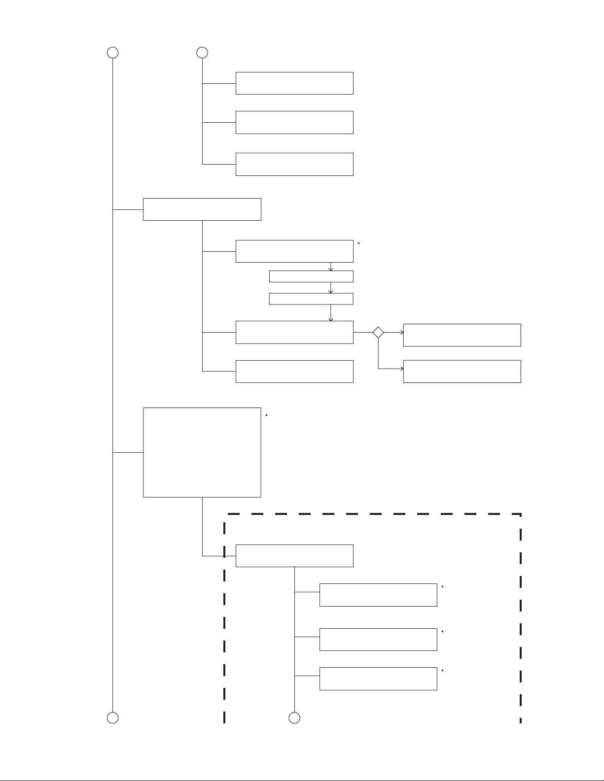
5.1 Feed section
SECTION 5
TROUBLESHOOTING
Is 2V at IC601 pin 63?
YES
Is 4V present at both
sides of the feed motor?
YES
Check the feed motor.
5.2 Focus section
5.3 Spindle section
NO
Is the wiring for IC601
pin 63 correct?
NO
Is 2V present at IC681
pins 1 and 27?
Check IC681.
When the lens is
moving:
Does the S-search
waveform appear at
IC681 pins 10 and 11?
NO
NO
YES
4V
YES
YES
Is 8V present at IC681
pins 3 and 12?
Check the vicinity of
IC601.
Check the feed motor
connection wiring.
NO
Check the circuits in
the vicinity of IC681
pins 13 and 14.
Check the pickup and
its connections.
NO
Check CD8V.
YES
YES
Is the disk rotated?
YES
Does the RF signal
appear at IC601 pin 26?
YES
Is the RF waveform
at IC601 pin 26 distorted?
YES
Proceed to the Tracking
section
5.4 Tracking section
When the disc is rotated
at first:
Is the tracking error
signal output at IC601
pin 57?
NO
Is 4V present between
IC681 pins 6 and 7?
Check the spindle motor
and its wiring.
NO
Check the circuits in
the vicinity of IC601
or the pickup.
NO
NO
Approx. 1.2V
YES
NO
YES
Check the circuits in
the vicinity of IC601
pins 48 and 49 .
Is 4V present at IC601
pin 64?
YES
Check the vicinity of
IC681.
NO
Check the pickup and
its connections.
NO
Check IC601.
1-32 (No.MA047)
Check IC601.
Page 33

5.5 Signal processing section
Is the sound output from
both channels (L, R)?
YES
Normal
NO
No sound from either
channel.
Is 9V present at IC165
/IC265 pin 16?
Is 5V present at IC365
pina 2, 3, 9 and 10?
Is 7V present at IC951
pina 1, 5, 7, 9, 17, 19
21 and 23?
YES
YES
YES
YES
Compare the L-ch and
NO
R-ch to locate the
defective point.
NO
Is 9V present at IC901
pin 10?
Check the connection
between IC901 pin10
and IC165/IC265 pin
16.
NO
Check the vicinity of
IC365.
NO
Check the power amp.
IC951.
YES
NO
Check IC901 and its
peripheral circuits.
Check the speaker
connector and its
connection.
(No.MA047)1-33
Page 34

5.6 Maintenance of laser pickup
(1) Cleaning the pick up lens
Before you replace the pick up, please try to clean the lens
with a alcohol soaked cotton swab.
(2) Life of the laser diode
When the life of the laser diode has expired, the following
symptoms will appear.
• The level of RF output (EFM output: amplitude of eye
pattern) will be low.
5.7 Replacement of laser pickup
Turn of the power switch and, disconnect the
power cord.
Replace the pickup with a normal one. (Refer
to "Removing the pickup unit" on the previous page.)
Is RF output
1.3 0.4Vp-p?
NO
Replace it.
YES
OK
(3) Semi-fixed resistor on the APC PC board
The semi-fixed resistor on the APC printed circuit board
which is attached to the pickup is used to adjust the laser
power.Since this adjustment should be performed to match
the characteristics of the whole optical block, do not touch
the semi-fixed resistor.
If the laser power is lower than the specified value, the laser diode is almost worn out, and the laser pickup should
be replaced. If the semi-fixed resistor is adjusted while the
pickup is functioning normally, the laser pickup may be
damaged due to excessive current.
Plug the power cord in, and turn the power on.
At this time, check that the laser emits for about
seconds and the objective lens moves up and down.
Note: Do not observe the laser beam directly.
Play a disc.
Check the eye-pattern at
RF test point.
Finish.
1-34 (No.MA047)
Page 35

5.8 16P CORD DIAGRAM
GN
GN/BK
VI/BK
VI
NC
BL/WH
RD
BK
RR+
RR-
FR-
FL+
FL-
RL+
WH
WH/BK
GY/BK
GY
BR
NC
OR/WH
YL
VI
VI/BK
GYFR+
GY/BK
WH
WH/BK
GN
BK
RD
BL
Black
Red
Blue
WH White
BR
Brown
OR/WH
BR
BL/WH
YL
RD
GN
VI
GY
YL
OR
Green
Violet
Gray
Yellow
Orange
ACC
MEMORY
ILL
TEL
REMOTE
VI/BK
VI
GY/BK
GY
WH
WH/BK
GN/BK
GN
RR
FR
FL
RL
REMOTE
ILL
RL-
Rear Right
Front Right
Front Left
Rear Left
Remote out
Illuminations Control
GN/BK
BK
ANT
ACC
TEL
GND
MEMORY
GND
Auto Antenna
ACC Line
Telephone Muting
Ground
Memory Backup Battery +
NC
NC
BL/WH
RD
BR
YL
OR/WH
BK
(No.MA047)1-35
Page 36

VICTOR COMPANY OF JAPAN, LIMITED
AV & MULTIMEDIA COMPANY CAR ELECTRONICS CATEGORY 10-1,1chome,Ohwatari-machi,Maebashi-city,371-8543,Japan
(No.MA047)
Printed in Japan
WPC
Page 37

PARTS LIST
[ KD-SHX701 ]
[ KD-SHX701T ]
* All printed circuit boards and its assemblies are not available as service parts.
KD-SHX701
Area suffix
E ----------- Continental Europe
KD-SHX701T
Area suffix
E ----------- Continental Europe
EX --------------- Central Europe
EU-----------------------------Turkey
- Contents -
Exploded view of general assembly and parts list (Block No.M1)
CD mechanism assembly and parts list (Block No.MB)
Electrical parts list (Block No.01~03)
Packing materials and accessories parts list (Block No.M3)
3- 2
3- 6
3- 9
3-18
MA047
3-1
Page 38

Exploded view of general assembly and parts list
8
Block No.
M
M
1
M
42
44
43
32
42
27
23
24
A
40
31
27
B
J
19
C
D
32
E
25
20
45
21
45
9
48
50
49
51
47
61
55
56
52
Front board
68
57
58
53
62
54
69
54
65
71
63
77
66
70
67
18
F
F'
66
45
33
66
64
a
17
11
7
13
6
12
G
16
G'
10
14
3-2
6059
Page 39

M
M
81
87
75
85
89
84
75
88
e
B
d
e
g
h
46
H
J
82
86
d
83
88
h
25
20
5
17
80
78
38
90
g
36
11
79
Main board
a
9
a
8
4
35
b
29
30
38
c
7
2
15
G
16
G'
F
10
c
76
G
28
3
b
1
34
15
39
F'
D
C
22
H
41
41
E
26
37
5
G'
73
39
72
34
74
40
3-3
Page 40

General Assembly
Block No. [M][1][M][M]
Symbol No. Part No. Part Name Description Local
1 GE20156-002A GEAR BKT UNIT
2 LV4 0847-002A SPACER
3 FSYH4036-100 SHEET
4 GE30968-001A LEVER BKT UNIT
5 GE30964-002 A L O W ER LEVER ASS
6 GE30975-003A F RONT BKT ASSY
7 QNZ0664-002 CAR CONNECTOR
8 QAL0587-001 FPC
9 FSYH4036-100 SHEET
10 GE 30972-001A DETACH LEVER
11 GE 30973-001A KICK LEVER
12 GE 40192-001A SHAFT
13 GE 40193-001A SHAFT
14 WDL123525 SLIT WASHER (x2)
15 WDL215025 WASHER (x2)
16 GE 40194-001A T SPRING
17 GE 40195-002A T SPRING
18 LV43971-001A ABSORBER (x2)
19 LV10884-001A TOP CHASSIS
20 LV35317-001A MECHA HEAT SINK
21 LV43854-003A COOLING RUBBER
22 GE 10074-001A BOTTOM CHASSIS
23 LV34930-006A F CHASSIS ASSY
24 GE 40156-001A BLIND
25 LV35233-001A EARTH SPRING2
26 GE 30974-001A FPC GUIDE
27 GE 40196-001A ABSORBER (x2)
28 LV35332-001A INSULATOR
29 LV43854-001A COOLING RUBBER
30 LV43854-002A COOLING RUBBER
31 GE 31206-003A HEAT SINK
32 QYSPSP2003M SCREW 2mm x 3mm(x2)
33 QYSPSGU2040M TA P SC R EW M2 x 4mm(x2)
34 LV42181-002A SPECIAL SCREW (x2)
35 LV40865-001A MINI SCREW (x2)
36 LV40865-001A MINI SCREW (x3)
37 LV40865-001A MINI SCREW
38 LV41200-001A SPECIAL SCREW (x2)
39 FSKZ4005-001 SCREW (x2)
40 QYSDST2604Z SCREW 2.6mm x 4mm(x2)
41 LV41200-001A SPECIAL SCREW (x2)
42 FSKZ4005-002 SCREW (x2)
43 QYSDST 2614Z TAPPI NG SCREW M2.6 x 14mm(x2)
44 QYSDST 2614Z TAPPI NG SCREW M2.6 x 14mm
45 QYSDST2605Z SCREW 2.6mm x 5mm(x3)
46 QYSDST2604Z SCREW 2.6mm x 4mm(x2)
47 LV34975-002A FRONT PANEL ASS SHX701E
47 LV34975-006A FRONT PANEL ASS SHX701TE,SHX701TEU,SHX701 TEX
48 LV34806-003A EJECT BUTTON SHX701E
48 LV34806-001A EJECT BUTTON SHX701TE,SHX701TEU,SHX701TEX
49 LV34807-001A EJECT BUTTO N BA
50 LV34808-003A POWER BUTTON SHX701E
50 LV34808-001A POWER BUTTON SHX701TE,SHX701TEU,SHX701TEX
51 LV43999-001A SHEET
52 LV34809-001A POWER BUTTON BA
53 LV34815-001A SHADING WALL 1
54 LV34805-001A SHADING WALL 2 (x2)
55 LV34810-001A VOL BUTTON
56 LV34816-001A SHADING WALL 3
57 LV34800-004A 3 BUTTON
58 LV34801-002A 4 BUTTON
59 LV34799-003A DETACH BUTTON SHX701E
59 LV34799-001A DETACH BUTTON SHX701TE,SHX701TEU,SHX701TEX
60 LV43723-001A COMPRESSION SPRING
61 LV34817-001A IR FILTER
62 LV34818-003A RESET BUTTON SHX701E
62 LV34818-001A RESET BUTTON SHX701TE,SHX701TEU,SHX701TEX
63 LV10882-001A REAR COVER
64 LV40848-051A SPACER(P)
65 LV34812-001A EARTH SPRING
66 VKZ4777-001 MINI SCREW (x6)
67 QYSPSPU1730M SCREW 1.7mm x 3mm
68 QLE0031-001 OEL MODULE
69 LV43972-001A OEL INSULATOR
3-4
Page 41

Symbol No. Part No. Part N ame Description Local
70 LV43889-001A SW PWB SHEE T
71 LV40848-050A SPACER(P)
72 LV34937-001A NAME PLATE SHX701E
72 LV35345-001A NAME PLATE SHX701TE,SHX701TEU,SHX701TEX
73 LV41843-002A LASER CA UTION
74 GE 40218-011A SHEET ( x2 )
75 GE 40101-001A PIN CAP (x8)
76 QJ J010-040904 SIN CR C- C WIR
77 QUQ105-3003AB FFC WIRE
78 LV43349-001A POWE IC BK T
79 LV43373-001A REG IC BKT
80 QMFZ039-150-T FUSE 15A
81 QAM0561-001 CAR CABLE
82 QAM0560-001 CAR CABLE
83 QAM0568-001 CAR CABLE
84 LV34596-004A REAR BRAC KET
85 LV43864-001A WIRE BRACKET
86 QY SDST2604Z SCREW 2.6mm x 4mm
87 QY SDST2604Z SCREW 2.6mm x 4mm
88 QY SDST2604Z SCREW 2.6mm x 4mm(x2)
89 QY SDST2604Z SCREW 2.6mm x 4mm
90 QY SDST2604Z SCREW 2.6mm x 4mm
3-5
Page 42

CD mechanism assembly and parts list
FLM-JC1-1D
98
96
97
91
93
30
Grease
=
JVS-1003
=
MOBIL-1
=
JVG-31N
=
JC-803B
26
25
92
94
95
b
87
88
86
Block No.
11
M
12
B
10
A
M
M
12
28
14
6
4
8
13
32
31
14
1
b
54
19
20
53
55
89
52
48
47
59
90
64
C
65
66
63
18
B
43
44
46
22
40
15
21
33
1
45
34
84
83
36
1
60
39
37
61
38
1.0
11.10mm 0.10mm
81
82
35
39
82
24
23
25
B
27
30
C
29
7
6
3
5
56
57
3
16
8
4
6
A
17
82
41
13
51
50
49
70
69
68
2
9
77
58
2
42
79
85
75
67
76
a
74
73
1
a
80
1.2 0.1mm
3-6
1
1
1
62
78
78
72
71
2
Page 43

CD mechanism
Symbol No. Part No. Part N ame Description Local
1 VKZ4539-026 MINI SCREW (x5)
2 LV10857-001A CHASSIS FRAME 2
3 LV30225-0J6A SPACER (x2)
4 LV35272-001A DAMPER(F) (x2)
5 LV35273-001A DAMPER(R)
6 QYSPSTU2045M TAP SCREW M2 x 4.5mm(x3)
7 LV43039-001A DAMPER SP.(R)
8 LV43849-001A DAMPER SP(F2) (x2)
9 LV43041-001A FLOATING SPRING (x2)
10 LV10675-001A TOP COVER
11 LV30225-0J5A SPACER
12 VKZ4539-026 MINI SCREW (x2)
13 LV33669-001A STOPPER ( x2)
14 VKZ4539-026 MINI SCREW (x2)
15 LV21615-001A CD CHASS IS A SSY
16 LV33608-001A GEAR HOL D ER
17 VKZ4539-026 MINI SCREW
18 LV43561-001A ABSORBER
19 LV30225-0J5A SPACER
20 LV33683-003A SLIDE CAM ASSY
21 LV33610-001A FLOATING ARM
22 LV33611-001A CONNECT A RM
23 LV33678-003A LOADING A. ASSY
24 LV43049-001A LOADING SHAFT
25 LV43052-003A ROLLER (x2)
26 LV33612-001A LOADING G EAR
27 QY W FM 124013 WASHER 4mm/1.2mm x 0. 1 3m m
28 LV43053-002A ROD(L)
29 LV43725-001A ROD(R)
30 LV43001-001A COLLAR (x2)
31 LV21285-001A PROTECTOR
32 LV43055-001A PROTECTOR SP.
33 QAR0144-003 MOTOR
34 LV43002-002A WORM GE AR
35 QYSPSPT2025M MINI SCREW 2mm x 2.5mm(x2)
36 LV33679-001A MOTOR H. ASS Y
37 LV33614-002A WORM WH EEL
38 QY W D L1230250 SLIT WASHER 3mm/1.2mm x 0. 25mm
39 VKZ4539-026 MINI SCREW (x2)
40 LV33615-001A GEAR 2
41 LV43057-003A IDLER ARM AS SY
42 QY W D L1635252 SLIT WASHER 3.5mm/1.6m m x 0.25mm
43 LV21286-001A CONTROL CAM
44 QY W D L1230250 SLIT WASHER 3mm/1.2mm x 0. 25mm
45 LV33616-001A LOAD.LOC K LEVER
46 LV43060-001A CAM SPRI N G
47 LV43005-001A GEAR 4
48 LV43006-001A GEAR 5
49 LV33617-001A GEAR 6
50 LV33618-002A LOADING G. ARM
51 QY W D L1635252 SLIT WASHER 3.5mm/1.6m m x 0.25mm
52 LV43007-001A GEAR 7
53 LV33619-002A GEAR 8
54 LV42132-001A E RING
55 QY W FM 215013 WASHER 5mm/2.1mm x 0. 1 3m m
56 LV33620-001A GEAR 9
57 LV43008-001A GEAR10
58 LV43061-001A LOAD SPRIN G
59 LV33621-001A FEED GEA R
60 LV33622-001A TRIGGER ARM
61 LV43062-001A FEED TRI.SP RI N G
62 QY SPSFT2040Z TAP SCREW M2 x 4mm
63 QAR0305-001 SPINDLE MOTOR
64 QYSPS PT1720M SCREW M1 .7 x 2 mm ( x2 )
65 LV43669-002A T.TABLE ASSY
66 QY W FM 214025 WASHER 4mm/2.1mm x 0. 2 5m m
67 QA L0563-001 PICK U P
68 LV34583-002A CD RACK PL ATE
69 LV34579-001A CD RACK SP R I N G
70 LV43903-001A MINI TAP SCREW
71 LV34580-001A P. S. SPRING
72 QYSPS GT1425M TAP SCREW 1. 4mm x 2.5m m
73 LV43670-001A LEAD SCREW
74 LV43010-001A L.S.GEAR
Block No. [M][B][M][M]
3-7
Page 44

Symbol No. Part No. Part Name Description Local
75 LV43011-001A THRUST SPRING
76 QYSPSFT2040Z TAP SCREW M2 x 4mm
77 LV21604-003A L.S.HOLDER 1
78 VKZ4539-026 MINI SCREW (x2)
79 LV34582-002A L.S.HOLDER 2
80 VKZ4539-026 MINI SCREW (x2)
81 LV34581-001A SUB GUIDE
82 VKZ4539-026 MINI SCREW (x3)
83 LV34915-001A SW LEVER
84 LV43898-001A S.L.SPRING
85 QYSPSFT2040Z TAP SCREW M2 x 4mm
86 LV34602-002A CLAMPER UNIT 2
87 LV34585-001A KICK ARM 2
88 LV43507-001A SPL WASHER
89 LV43070-001A CLAMPER SPRING
90 LV43355-001A CLAMPER2 SPRING
91 LV30225-0J6A SPACER
92 LV21616-003A FRONT UN I T 2
93 VKZ4539-026 MINI SCREW
94 LVB30016-001A SW FPC2
95 NSW0187-001 SWITCH S1
96 NSW0187-001 SWITCH S2
97 NSW0187-001 SWITCH S3
98 VKZ4539-025 MINI SCREW (x2)
3-8
Page 45

Electrical parts list
Main board
Block No. [0][1][0][0]
Symbol No.
IC10 SAF7730HV/N114F IC
IC11 PHK04P02T-X POWER MOS FET
IC165 BD3805F-X IC
IC171 LA2900M-X IC
IC265 BD3805F-X IC
IC271 LA2900M-X IC
IC360 NJM4580V-X IC
IC362 NJM4565V-X IC
IC365 CD4066BPW-X IC
IC381 NJM4565V-X IC
IC401 AK7740VT IC
IC411 JCV8009-W IC
IC412 AK4385VT-X IC
IC701 MN101E01LCX IC
IC702 PST9121N-X IC
IC703 BR24L32F-W-X IC
IC710 SN74AHCT126PW-X IC(DIGITAL)
IC901 HA13164A IC
IC921 NAL0026-001X D/D CO NVERTER
IC951 TB2901HB IC
IC971 NAL0024-002X D/D CO NVERTER
IC973 TA48033F-X IC
IC975 BA33BC0FP-X IC
IC976 BA00BC0WFP-X IC(D IGITAL)
IC991 BA6956AN IC
Q1 2SB815/7/-X TRANSISTOR
Q2 UN2211-X TRANSISTOR
Q30 UN2211-X TRANSISTOR
Q703 UN2213-X DIGI TRANSISTOR
Q791 UN2211-X TRANSISTOR
Q901 UN2111-X TRANSISTOR
Q902 UN2211-X TRANSISTOR
Q903 2SB709A/QR/-X TRANSISTOR
Q905 UN2111-X TRANSISTOR
Q906 UN2211-X TRANSISTOR
Q907 UN2111-X TRANSISTOR
Q908 UN2211-X TRANSISTOR
Q921 2SD601A/RS/-X TRANSISTOR
Q922 UN2211-X TRANSISTOR
Q941 UN2111-X TRANSISTOR
Q942 UN2113-X TRANSISTOR
Q943 UN2113-X TRANSISTOR
Q951 2SD601A/QR/-X TRANSISTOR
Q952 UN2211-X TRANSISTOR
Q953 UN2213-X DIGI TRANSISTOR
Q954 UN2113-X TRANSISTOR
Q971 2SD601A/RS/-X TRANSISTOR
Q972 UN2211-X TRANSISTOR
Q991 UN2211-X TRANSISTOR
Q1451 2SD2114K/VW/-X TRANS ISTOR
Q1452 2SD2114K/VW/-X TRANS ISTOR
Q2451 2SD2114K/VW/-X TRANS ISTOR
Q2452 2SD2114K/VW/-X TRANS ISTOR
Q3655 UN2211-X TRANSISTOR
Q3656 UN2211-X TRANSISTOR
Q3801 2SD1781 K/QR/-X TRANSISTOR
Q7201 UN2211-X TRANSISTOR
Q7202 UN2211-X TRANSISTOR
Q9001 2SD601A/QR/-X TRANSISTOR
Q9051 UN2211-X TRANSISTOR
D1 1SS355-X SI DI ODE
D2 1SS355-X SI DI ODE
D701 1SS35 5- X SI DIODE
D702 1SS35 5- X SI DIODE
D709 UDZS5.6B-X Z DIODE 1.5k
D710 UDZS5.6B-X Z DIODE 1.5k
D711 UDZS5.6B-X Z DIODE 1.5k
D712 UDZS5.6B-X Z DIODE 1.5k
D713 UDZS5.6B-X Z DIODE 1.5k
D714 UDZS5.6B-X Z DIODE 1.5k
Part No. Part Nam e Description Local
Ω
1/10W J
Ω
1/10W J
Ω
1/10W J
Ω
1/10W J
Ω
1/10W J
Ω
1/10W J
Symbol No.
D715 UDZS5.6B-X Z DIODE 1.5kΩ 1/10W J
D716 UDZS5.6B-X Z DIODE 1.5k
D717 UDZS5.6B-X Z DIODE 1.5k
D718 SML-310LT/MN/-X LED
D719 SML-310LT/MN/-X LED
D722 UDZS5.6B-X Z DIODE 1.5k
D901 1N5401-F64 D IODE
D904 RB160M-30-X S B DIODE
D905 RB160M-30-X S B DIODE
D921 1SR154-400-X DIODE
D940 UDZS3.3B-X Z DIODE
D941 UDZS11B-X Z DIODE
D942 MA152WA-X DIODE
D943 MA152WA-X DIODE
D944 1SS355-X SI DIODE
D952 UDZS11B-X Z DIODE
D971 1SR154-400-X DIODE
D975 RB160M-30-X S B DIODE
D976 RB160M-30-X S B DIODE
D991 UDZS3.9B-X Z DIODE
D1451 MA152WA-X DIODE
D2451 MA152WA-X DIODE
D3801 1SS355-X SI DIODE
D9051 MA152WA-X DIODE
C1 NCB31HK-222X C CAPAC I TOR 2200pF 50V K
C2 QERF1CM-476Z E CAPACITOR 47uF 16V M
C3 NCS31HJ-391X C CAPACITOR 390pF 50V J
C4 QERF1CM-476Z E CAPACITOR 47uF 16V M
C5 NCS31HJ-391X C CAPACITOR 390pF 50V J
C7 NCS31HJ-391X C CAPACITOR 390pF 50V J
C13 NCS31H J-391X C CAPACITOR 390pF 50V J
C14 NCS31H J-391X C CAPACITOR 390pF 50V J
C21 NCB31HK-102 X C CAPACIT OR 1000pF 50V K
C22 NCB31HK-102 X C CAPACIT OR 1000pF 50V K
C28 NBE 20 JM- 10 6X TA E CAPACITOR 10uF 6.3V M
C29 NBE 20 JM- 10 6X TA E CAPACITOR 10uF 6.3V M
C31 NCS31H J-221X C CAPACITOR 220pF 50V J
C32 NCS31HJ-180X C CAPACITOR 18pF 50V J
C33 NCS31HJ-100X C CAPACITOR 10pF 50V J
C34 NBE 20 JM- 47 5X TA E CAPACITOR 4.7uF 6.3V M
C35 NCB31C K-104X C CAPACITOR 0.1uF 16V K
C36 NCS31H J-181X C CAPACITOR 180pF 50V J
C37 NCB31H K-103X C CAPACITOR 0.01uF 50V K
C40 NDC31H J-101X C CAPACITOR 100pF 50V J
C41 NCB31C K-104X C CAPACITOR 0.1uF 16V K
C42 NCB31C K-104X C CAPACITOR 0.1uF 16V K
C43 NCB31C K-104X C CAPACITOR 0.1uF 16V K
C44 NBE 20 JM- 47 5X TA E CAPACITOR 4.7uF 6.3V M
C45 NBE 20 JM- 47 5X TA E CAPACITOR 4.7uF 6.3V M
C46 NCB31C K-104X C CAPACITOR 0.1uF 16V K
C47 NBE 20 JM- 47 5X TA E CAPACITOR 4.7uF 6.3V M
C48 QERF0JM-107Z E CAPACITOR 100uF 6.3V M
C50 NBE 20 JM- 22 6X TA E CAPACITOR 22uF 6.3V M
C51 NCB31C K-47 3X C CAPACITOR 0.047uF 16V K
C53 NCB21C K-10 5X C CAPACITOR 1uF 16V K
C54 NBE 40 JM- 47 6X TA E CAPACITOR 47uF 6.3V M
C55 NCB31C K-104X C CAPACITOR 0.1uF 16V K
C56 NDC31H J-101X C CAPACITOR 100pF 50V J
C57 NDC31H J-101X C CAPACITOR 100pF 50V J
C58 NBE 20 JM- 47 5X TA E CAPACITOR 4.7uF 6.3V M
C59 NCB31C K-33 3X C CAPACITOR 0.033uF 16V K
C60 NCB31C K-104X C CAPACITOR 0.1uF 16V K
C61 QERF0JM-107Z E CAPACITOR 100uF 6.3V M
C62 QERF0JM-227Z E CAPACITOR 220uF 6.3V M
C63 NCB31E K-22 3X C CAPACITOR 0.0 22uF 2 5V K
C64 NCB21C K-10 5X C CAPACITOR 1uF 16V K
C65 NCB31H K-47 1X C CAPACITOR 470pF 50V K
C66 NDC31H J-101X C CAPACITOR 100pF 50V J
C67 NDC31H J-101X C CAPACITOR 100pF 50V J
C68 NDC31H J-101X C CAPACITOR 100pF 50V J
C69 NCS31H J-221X C CAPACITOR 220pF 50V J
C70 NDC31H J-101X C CAPACITOR 100pF 50V J
C71 NDC31H J-101X C CAPACITOR 100pF 50V J
C72 NRSA63J-47 3X MG RESISTOR 47k
C73 NRSA63J-47 3X MG RESISTOR 47k
Part No. Part Name Descriptio n Local
Ω
1/10W J
Ω
1/10W J
Ω
1/10W J
Ω
1/16W J
Ω
1/16W J
3-9
Page 46

Symbol No.
Part No. Part Name Description Local
Symbol No.
Part No. Part Name Description Local
C74 NRSA63J-473X MG RES ISTOR 47kΩ 1/16W J
C76 NCB31EK-223X C CAPAC I TOR 0.022uF 25V K
C77 NCB3 1HK-103X C CAPACITOR 0.01uF 50V K
C78 NCB3 1HK-103X C CAPACITOR 0.01uF 50V K
C79 NBE20JM-106X TA E CAPACITOR 10uF 6.3V M
C80 NCB31EK-223X C CAPAC I TOR 0.022uF 25V K
C81 NCS31HJ-221X C CAPACITOR 220pF 50V J
C82 NCB31EK-223X C CAPAC I TOR 0.022uF 25V K
C85 NCF31EZ-104X C CAPACITOR 0.1uF 25V Z
C86 NCF31EZ-104X C CAPACITOR 0.1uF 25V Z
C87 QERF1HM-104Z E CAPACITOR 0.1uF 50V M
C88 NBE20JM-106X TA E CAPACITOR 10uF 6.3V M
C701 NCS31HJ-8R0X C CAPACITOR 10pF 50V J
C702 NCS31HJ-8R0X C CAPACITOR 10pF 50V J
C703 NCS31HJ-330X C CAPACITOR 33pF 50V J
C704 NCS31HJ-180X C CAPACITOR 18pF 50V J
C705 QERF1AM-227Z E CAPACITOR 220uF 10V M
C708 QERF1AM-106Z E CAPACITOR 10uF 10V M
C709 NCB31HK-103X C CAPACITOR 0.01uF 50V K
C710 NCB31CK-473X C CAPACITOR 0.047uF 16V K
C712 NCB31HK-103X C CAPACITOR 0.01uF 50V K
C713 QE R F0JM-337Z E CAPACITOR 330uF 6.3V M
C714 NCB31HK-103X C CAPACITOR 0.01uF 50V K
C715 NCB31CK-104X C CAPACITOR 0.1uF 16V K
C716 NCB31HK-471X C CAPACITOR 470pF 50V K
C717 NCB31HK-103X C CAPACITOR 0.01uF 50V K
C718 QE R F0JM-337Z E CAPACITOR 330uF 6.3V M
C719 QE R F0JM-337Z E CAPACITOR 330uF 6.3V M
C720 NCB31HK-103X C CAPACITOR 0.01uF 50V K
C723 ND C31HJ-101X C CAPACITOR 100p F 50V J
C724 NCF31CZ-473X C CAPACITOR 0.047uF 16V Z
C725 NCB31HK-103X C CAPACITOR 0.01uF 50V K
C726 NCB31HK-103X C CAPACITOR 0.01uF 50V K
C776 QE RF0JM-476Z E CAPACITOR 47uF 6.3V M
C777 NCB31HK-103X C CAPACITOR 0.01uF 50V K
C791 QERF1HM-104Z E CAPACITOR 0.1uF 50V M
C901 QE Z0675-338 E CAPACITOR 3300uF
C902 QERF1CM-226Z E CAPACITOR 22uF 16V M
C903 QERF1CM-226Z E CAPACITOR 22uF 16V M
C904 NCB31HK-103X C CAPACITOR 0.01uF 50V K
C905 QERF1AM-107Z E CAPACITOR 100uF 10V M
C906 NCB31CK-104X C CAPACITOR 0.1uF 16V K
C907 NCB31HK-103X C CAPACITOR 0.01uF 50V K
C908 QERF1AM-227Z E CAPACITOR 220uF 10V M
C910 QERF1CM-106Z E CAPACITOR 10uF 16V M
C911 NCB3 1CK-104X C C APACITOR 0.1u F 16V K
C912 QERF1HM-225Z E CAPACITOR 2.2uF 50V M
C917 NCB31HK-103X C CAPACITOR 0.01uF 50V K
C921 QERF1CM-107Z E CAPACITOR 100uF 16V M
C922 NCF31EZ-104X C C APACITOR 0.1uF 25V Z
C923 QERF1EM-107Z E CAPACITOR 100uF 25V M
C941 QERF1CM-107Z E CAPACITOR 100uF 16V M
C942 QE R F0JM-107Z E CAPACITOR 100uF 6.3V M
C950 QERF1CM-476Z E CAPACITOR 47uF 16V M
C951 QERF1CM-226Z E CAPACITOR 22uF 16V M
C952 NCB31HK-103X C CAPACITOR 0.01uF 50V K
C953 QERF1CM-106Z E CAPACITOR 10uF 16V M
C954 QERF1HM-475Z E CAPACITOR 4.7uF 50V M
C955 QERF1HM-225Z E CAPACITOR 2.2uF 50V M
C961 ND C31HJ-101X C CAPACITOR 100p F 50V J
C962 ND C31HJ-101X C CAPACITOR 100p F 50V J
C963 ND C31HJ-101X C CAPACITOR 100p F 50V J
C964 ND C31HJ-101X C CAPACITOR 100p F 50V J
C965 ND C31HJ-101X C CAPACITOR 100p F 50V J
C966 ND C31HJ-101X C CAPACITOR 100p F 50V J
C967 ND C31HJ-101X C CAPACITOR 100p F 50V J
C968 ND C31HJ-101X C CAPACITOR 100p F 50V J
C970 QERF1HM-225Z E CAPACITOR 2.2uF 50V M
C971 NCB31CK-104X C CAPACITOR 0.1uF 16V K
C972 QERF1CM-107Z E CAPACITOR 100uF 16V M
C973 NCB31CK-104X C CAPACITOR 0.1uF 16V K
C974 QERF1CM-107Z E CAPACITOR 100uF 16V M
C975 QERF1CM-107Z E CAPACITOR 100uF 16V M
C976 NCB31HK-103X C CAPACITOR 0.01uF 50V K
C977 QE R F0JM-107Z E CAPACITOR 100uF 6.3V M
C983 QERF1CM-107Z E CAPACITOR 100uF 16V M
C984 NCB31HK-103X C CAPACITOR 0.01uF 50V K
C985 QE R F0JM-227Z E CAPACITOR 220uF 6.3V M
C987 Q ERF1CM-107Z E CAPACITOR 100uF 16V M
C988 NCB31HK-103X C CAPACITOR 0.01uF 50V K
C989 QERF0JM-107Z E CAPACITOR 100uF 6.3V M
C991 Q ERF1AM-107Z E CAPACITOR 100uF 10V M
C992 NCB31C K-473X C CA PACITOR 0.047uF 16V K
C993 NCB31HK-103X C CAPACITOR 0.01uF 50V K
C994 NCF31CZ-473X C CAPACITOR 0.047uF 16V Z
C995 NCB31HK-103X C CAPACITOR 0.01uF 50V K
C1401 QERF1HM-225Z E CAPACITOR 2.2uF 50V M
C1402 NCB31HK- 472X C CAPACITOR 4700pF 50V K
C1403 N D C31HJ-101X C CAPACITOR 100pF 50V J
C1404 NCB31CK- 102X C CAPACITOR 1000pF 16V K
C1451 N D C31HJ-101X C CAPACITOR 100pF 50V J
C1452 N D C31HJ-101X C CAPACITOR 100pF 50V J
C1501 N D C31HJ-101X C CAPACITOR 100pF 50V J
C1502 NCB30JK-105X C CAPACITOR 1uF 6.3V K
C1601 NCB31HK- 102X C CAPACITOR 1000pF 50V K
C1602 NCS31HJ-391X C CAPACITOR 390pF 50V J
C1603 NCS31HJ-391X C CAPACITOR 390pF 50V J
C1607 NBE41AM-476X TA E CAPACITOR 47uF 10V M
C1621 N D C31HJ-101X C CAPACITOR 100pF 50V J
C1622 NCS31HJ-821X C CAPACITOR 820pF 50V J
C1623 NBE41AM-476X TA E CAPACITOR 47uF 10V M
C1624 QERF1EM-475Z E CAPACITOR 4.7uF 25V M
C1625 NCS31HJ-121X C CAPACITOR 120pF 50V J
C1651 QERF1CM-106Z E CAPACITOR 10uF 16V M
C1652 QTE1H52-105Z E CAPACITOR 1uF 50V
C1653 QERF1HM -105Z E CAPACITOR 1uF 50V M
C1654 QERF1CM-106Z E CAPACITOR 10uF 16V M
C1655 NCF31EZ-104X C CAPACITOR 0.1uF 25V Z
C1700 QTE1E52-475Z E CAP AC I TOR 4.7uF 25V
C1701 QERF1CM-226Z E CAPACITOR 22uF 16V M
C1702 NCB31CK-104X C CAPACITOR 0.1uF 16V K
C1703 QER F1AM-107Z E CAPACITOR 100uF 10V M
C1704 NCB31HK- 152X C CAPACITOR 1500pF 50V K
C1705 QERF1EM-475Z E CAPACITOR 4.7uF 25V M
C1720 QTE1E52-475Z E CAP AC I TOR 4.7uF 25V
C1721 QERF1CM-226Z E CAPACITOR 22uF 16V M
C1722 NCB31CK-104X C CAPACITOR 0.1uF 16V K
C1723 QER F1AM-107Z E CAPACITOR 100uF 10V M
C1724 NCB31HK- 152X C CAPACITOR 1500pF 50V K
C1725 QERF1EM-475Z E CAPACITOR 4.7uF 25V M
C1751 NFV81CM -105 X MF CAPACITOR 1u F 16V M
C1752 N D C31HJ-101X C CAPACITOR 100pF 50V J
C1771 NFV81CM -105 X MF CAPACITOR 1u F 16V M
C1772 N D C31HJ-101X C CAPACITOR 100pF 50V J
C1801 NCB31CK-104X C CAPACITOR 0.1uF 16V K
C2401 QERF1HM-225Z E CAPACITOR 2.2uF 50V M
C2402 NCB31HK- 472X C CAPACITOR 4700pF 50V K
C2403 N D C31HJ-101X C CAPACITOR 100pF 50V J
C2404 NCB31CK- 102X C CAPACITOR 1000pF 16V K
C2451 N D C31HJ-101X C CAPACITOR 100pF 50V J
C2452 N D C31HJ-101X C CAPACITOR 100pF 50V J
C2501 N D C31HJ-101X C CAPACITOR 100pF 50V J
C2502 NCB30JK-105X C CAPACITOR 1uF 6.3V K
C2601 NCB31HK- 102X C CAPACITOR 1000pF 50V K
C2602 NCS31HJ-391X C CAPACITOR 390pF 50V J
C2603 NCS31HJ-391X C CAPACITOR 390pF 50V J
C2607 NBE41AM-476X TA E CAPACITOR 47uF 10V M
C2621 N D C31HJ-101X C CAPACITOR 100pF 50V J
C2622 NCS31HJ-821X C CAPACITOR 820pF 50V J
C2623 NBE41AM-476X TA E CAPACITOR 47uF 10V M
C2624 QERF1EM-475Z E CAPACITOR 4.7uF 25V M
C2625 NCS31HJ-121X C CAPACITOR 120pF 50V J
C2651 QERF1CM-106Z E CAPACITOR 10uF 16V M
C2652 QTE1H52-105Z E CAPACITOR 1uF 50V
C2653 QERF1HM -105Z E CAPACITOR 1uF 50V M
C2654 QERF1CM-106Z E CAPACITOR 10uF 16V M
C2655 NCF31EZ-104X C CAPACITOR 0.1uF 25V Z
C2700 QTE1E52-475Z E CAP AC I TOR 4.7uF 25V
C2701 QERF1CM-226Z E CAPACITOR 22uF 16V M
C2702 NCB31CK-104X C CAPACITOR 0.1uF 16V K
C2703 QER F1AM-107Z E CAPACITOR 100uF 10V M
C2704 NCB31HK- 152X C CAPACITOR 1500pF 50V K
C2705 QERF1EM-475Z E CAPACITOR 4.7uF 25V M
C2720 QTE1E52-475Z E CAP AC I TOR 4.7uF 25V
C2721 QERF1CM-226Z E CAPACITOR 22uF 16V M
C2722 NCB31CK-104X C CAPACITOR 0.1uF 16V K
3-10
Page 47

Symbol No.
Part No. Part Nam e Description Local
Symbol No.
Part No. Part Name Descriptio n Local
C2723 QERF1AM-107Z E CAPACITOR 100uF 10V M
C2724 NCB31HK-15 2X C CAPACITOR 1500pF 50V K
C2725 QERF1EM-475Z E CAPACITOR 4.7uF 25V M
C2751 NFV81CM-105X MF CAPACITOR 1uF 16V M
C2752 NDC31HJ-101X C CAPACITOR 100pF 50V J
C2771 NFV81CM-105X MF CAPACITOR 1uF 16V M
C2772 NDC31HJ-101X C CAPACITOR 100pF 50V J
C2801 NCB31CK-22 4X C CAPACITOR 0.22uF 16V K
C3401 Q ERF0JM-476Z E CAPACITOR 47uF 6.3V M
C3402 NCB31CK-473X C CAPACITOR 0.047uF 16V K
C3403 NCB31CK-473X C CAPACITOR 0.047uF 16V K
C3451 NCB31CK-473X C CAPACITOR 0.047uF 16V K
C3452 NDC31HJ-101X C CAPACITOR 100pF 50V J
C3501 NCB31CK-473X C CAPACITOR 0.047uF 16V K
C3603 Q ERF1CM-226Z E CAPACITOR 22uF 16 V M
C3623 Q ERF1CM-226Z E CAPACITOR 22uF 16 V M
C3655 NCF31EZ-104X C CAPACITOR 0.1uF 25V Z
C3701 QERF1AM-476Z E CAPACITOR 47 uF 10V M
C3721 QERF1AM-476Z E CAPACITOR 47 uF 10V M
C3801 NCB31HK-33 2X C CAPACITOR 3300pF 50V K
C3803 QERF1EM-475Z E CAPACITOR 4.7uF 25V M
C3804 QERF1EM-475Z E CAPACITOR 4.7uF 25V M
C3805 Q ERF0JM-476Z E CAPACITOR 47uF 6.3V M
C3806 NCB31HK-22 2X C CAPACITOR 2200pF 50V K
C3807 NCB31CK-473X C CAPACITOR 0.047uF 16V K
C3808 NCF31EZ-104X C CAPACITOR 0.1uF 25V Z
C3809 NCB31CK-333X C CAPACITOR 0.033uF 16V K
C3810 NCB31CK-473X C CAPACITOR 0.047uF 16V K
C3811 NCB31HK-10 3X C CAPACITOR 0.01uF 50V K
C4001 NDC31HJ-8R 0X C CAPACITOR 8pF 50V J
C4002 NDC31HJ-120X C CAPACITOR 12pF 50V J
C4010 NCB31HK-10 2X C CAPACITOR 1000pF 50V K
C4011 NBE20JM-106X TA E CAPACITOR 10uF 6.3V M
C4012 NCB31HK-10 2X C CAPACITOR 1000pF 50V K
C4027 NCB31HK-10 3X C CAPACITOR 0.01uF 50V K
C4028 NCB31HK-10 3X C CAPACITOR 0.01uF 50V K
C4030 NCB31HK-10 2X C CAPACITOR 1000pF 50V K
C4031 NBE20JM-106X TA E CAPACITOR 10uF 6.3V M
C4032 NBE20JM-106X TA E CAPACITOR 10uF 6.3V M
C4033 NCB31HK-10 2X C CAPACITOR 1000pF 50V K
C4034 NCB31HK-10 2X C CAPACITOR 1000pF 50V K
C4035 NBE20JM-106X TA E CAPACITOR 10uF 6.3V M
C4036 NCB31HK-10 2X C CAPACITOR 1000pF 50V K
C4038 NCB31HK-10 2X C CAPACITOR 1000pF 50V K
C4050 NCF31CZ-473X C CAPACITOR 0.047uF 16V Z
C4100 NBE20JM-106X TA E CAPACITOR 10uF 6.3V M
C4101 NCF31CZ-104X C CAPACITOR 0.1uF 16V Z
C4102 NCF31CZ-473X C CAPACITOR 0.047uF 16V Z
C4130 NCF31CZ-104X C CAPACITOR 0.1uF 16V Z
C4131 NBE40JM-476X TA E CAPACITOR 47uF 6.3V M
C4132 NDC31HJ-101X C CAPACITOR 100pF 50V J
C4133 NCS31HJ-4 71X C CAPACITOR 470pF 50V J
C4134 QERF1AM-107Z E CAPACITOR 100uF 10V M
C7101 NCB31HK-10 3X C CAPACITOR 0.01uF 50V K
C7116 NDC31HJ-101X C CAPACITOR 100pF 50V J
C7117 NDC31HJ-101X C CAPACITOR 100pF 50V J
C7201 NCB31HK-10 3X C CAPACITOR 0.01uF 50V K
C7202 NCB31HK-10 3X C CAPACITOR 0.01uF 50V K
C7203 NCB31HK-10 3X C CAPACITOR 0.01uF 50V K
C7204 NCB31HK-10 3X C CAPACITOR 0.01uF 50V K
C9001 Q ERF1CM-106Z E CAPACITOR 10uF 16 V M
C9051 NCB31CK-104X C CAPACITOR 0.1uF 16V K
Ω
R2 NRSA63J-1 02X MG RESISTOR 1k
R3 NRSA63J-0R0X MG RESISTOR 0
R4 NRSA63J-0R0X MG RESISTOR 0
R5 NRSA63J-3 31X MG RESISTOR 330
R6 NRSA63J-3 31X MG RESISTOR 330
R7 NRSA63J-1 01X MG RESISTOR 100
R8 NRSA63J-1 01X MG RESISTOR 100
R9 NRSA63J-2 73X MG RESISTOR 27k
R10 NR SA63J-273X MG RESI STOR 27 k
R11 N RS181J-100X MG RESISTOR 10
R12 NR SA63J-103X MG RESI STOR 10 k
R13 NR SA63J-102X MG RESI STOR 1k
R40 NR SA63J-101X MG RESI STOR 10 0
R41 NR SA63J-100X MG RESI STOR 10
R42 NR SA63J-222X MG RESI STOR 2. 2 k
1/16W J
Ω
1/16W J
Ω
1/16W J
Ω
1/16W J
Ω
1/16W J
Ω
1/16W J
Ω
1/16W J
Ω
1/16W J
Ω
1/16W J
Ω
1/8W J
Ω
1/16W J
Ω
1/16W J
Ω
1/16W J
Ω
1/16W J
Ω
1/16W J
R43 NRSA63J-22 2X MG RESISTOR 2.2kΩ 1/16W J
R44 NRSA63J-0R 0X MG RESISTOR 0
R45 NRSA02J-0R 0X MG RESISTOR 0
R48 NRSA02J-0R 0X MG RESISTOR 0
R49 NRSA63J-10 3X MG RESISTOR 10k
R58 NRSA63J-47 3X MG RESISTOR 47k
R60 NRSA02J-10 0X MG RESISTOR 10
R63 NRSA63J-10 1X MG RESISTOR 100
R64 NRSA63J-10 1X MG RESISTOR 100
R65 NRSA63J-10 1X MG RESISTOR 100
R66 NRSA63J-10 1X MG RESISTOR 100
R67 NRSA63J-10 1X MG RESISTOR 100
R68 NRSA63J-10 1X MG RESISTOR 100
R69 NRSA63J-10 1X MG RESISTOR 100
R70 NRSA63J-10 1X MG RESISTOR 100
R71 NRSA63J-10 1X MG RESISTOR 100
R72 NRSA63J-10 1X MG RESISTOR 100
R73 NRSA63J-10 1X MG RESISTOR 100
R74 NRSA63J-10 1X MG RESISTOR 100
R75 NRSA63J-10 1X MG RESISTOR 100
R76 NRSA63J-10 1X MG RESISTOR 100
R77 NRSA63J-10 1X MG RESISTOR 100
R78 NRSA63J-10 1X MG RESISTOR 100
R82 NRSA63J-0R 0X MG RESISTOR 0
R84 NRSA63J-0R 0X MG RESISTOR 0
R85 NRSA63J-0R 0X MG RESISTOR 0
R91 NRSA63J-0R 0X MG RESISTOR 0
R92 NRSA63J-0R 0X MG RESISTOR 0
R93 NRSA63J-0R 0X MG RESISTOR 0
R701 NRSA63J-681X MG RES ISTOR 680
R702 NRSA63J-473X MG RES ISTOR 47k
R703 NRSA63J-106X MG RES ISTOR 10M
R704 NRSA63J-473X MG RES ISTOR 47k
R705 NRSA63J-221X MG RES ISTOR 220
R706 NRSA63J-102X MG RES ISTOR 1k
R707 NRSA63J-221X MG RES ISTOR 220
R708 NRSA63J-273X MG RES ISTOR 27k
R709 NRSA63J-101X MG RES ISTOR 100
R713 NRSA63J-822X MG RES ISTOR 8.2k
R714 NRSA63J-102X MG RES ISTOR 1k
R715 NRSA63J-102X MG RES ISTOR 1k
R716 NRSA63J-102X MG RES ISTOR 1k
R717 NRSA63J-102X MG RES ISTOR 1k
R719 NRSA63J-0R0X MG RESISTOR 0
R720 NRSA63J-102X MG RES ISTOR 1k
R721 NRSA63J-102X MG RES ISTOR 1k
R722 NRSA63J-101X MG RES ISTOR 100
R723 NRSA63J-101X MG RES ISTOR 100
R724 NRSA63J-101X MG RES ISTOR 100
R725 NRSA63J-103X MG RES ISTOR 10k
R727 NRSA63J-0R0X MG RESISTOR 0
R729 NRSA63J-102X MG RES ISTOR 1k
R730 NRSA63J-102X MG RES ISTOR 1k
R731 NRSA63J-0R0X MG RESISTOR 0
R732 NRSA63J-0R0X MG RESISTOR 0
R733 NRSA63J-102X MG RES ISTOR 1k
R734 NRSA63J-271X MG RES ISTOR 270
R735 NRSA63J-103X MG RES ISTOR 10k
R736 NRSA63J-271X MG RES ISTOR 270
R737 NRSA63J-102X MG RES ISTOR 1k
R738 NRSA63J-102X MG RES ISTOR 1k
R740 NRSA63J-0R0X MG RESISTOR 0
R741 NRSA63J-102X MG RES ISTOR 1k
R742 NRSA63J-102X MG RES ISTOR 1k
R743 NRSA63J-102X MG RES ISTOR 1k
R744 NRSA63J-102X MG RES ISTOR 1k
R745 NRSA63J-102X MG RES ISTOR 1k
R746 NRSA63J-102X MG RES ISTOR 1k
R747 NRSA63J-473X MG RES ISTOR 47k
R748 NRSA63J-682X MG RES ISTOR 6.8k
R749 NRSA63J-102X MG RES ISTOR 1k
R750 NRSA63J-102X MG RES ISTOR 1k
R751 NRSA63J-123X MG RES ISTOR 12k
R752 NRSA63J-102X MG RES ISTOR 1k
R753 NRSA63J-0R0X MG RESISTOR 0
R754 NRSA63J-223X MG RES ISTOR 22k
R755 NRSA63J-221X MG RES ISTOR 220
R756 NRSA63J-221X MG RES ISTOR 220
Ω
1/16W J
Ω
1/10W J
Ω
1/10W J
Ω
1/16W J
Ω
1/16W J
Ω
1/10W J
Ω
1/16W J
Ω
1/16W J
Ω
1/16W J
Ω
1/16W J
Ω
1/16W J
Ω
1/16W J
Ω
1/16W J
Ω
1/16W J
Ω
1/16W J
Ω
1/16W J
Ω
1/16W J
Ω
1/16W J
Ω
1/16W J
Ω
1/16W J
Ω
1/16W J
Ω
1/16W J
Ω
1/16W J
Ω
1/16W J
Ω
1/16W J
Ω
1/16W J
Ω
1/16W J
Ω
1/16W J
Ω
1/16W J
Ω
1/16W J
Ω
Ω
1/16W J
Ω
1/16W J
Ω
1/16W J
Ω
1/16W J
Ω
1/16W J
Ω
1/16W J
Ω
Ω
1/16W J
Ω
1/16W J
Ω
1/16W J
Ω
1/16W J
Ω
1/16W J
Ω
1/16W J
Ω
1/16W J
Ω
1/16W J
Ω
1/16W J
Ω
1/16W J
Ω
1/16W J
Ω
1/16W J
Ω
1/16W J
Ω
1/16W J
Ω
1/16W J
Ω
1/16W J
Ω
1/16W J
Ω
1/16W J
Ω
1/16W J
Ω
1/16W J
Ω
1/16W J
Ω
1/16W J
Ω
1/16W J
Ω
1/16W J
Ω
1/16W J
Ω
1/16W J
Ω
1/16W J
Ω
1/16W J
Ω
1/16W J
Ω
1/16W J
Ω
Ω
1/16W J
Ω
1/16W J
Ω
1/16W J
Ω
1/16W J
Ω
1/16W J
Ω
1/16W J
Ω
1/16W J
Ω
1/16W J
1/16W J
1/16W J
1/16W J
3-11
Page 48

Symbol No.
Part No. Part Name Description Local
Symbol No.
Part No. Part Name Description Local
R757 NR SA63J-102X MG RES ISTOR 1kΩ 1/16W J
R758 NR SA63J-473X MG RES ISTOR 47k
R759 NR SA63J-102X MG RES ISTOR 1k
R760 NR SA63J-102X MG RES ISTOR 1k
R761 NR SA63J-0R0X MG R ESISTOR 0
R762 NR SA63J-102X MG RES ISTOR 1k
R763 NR SA63J-102X MG RES ISTOR 1k
R764 NR SA63J-102X MG RES ISTOR 1k
R765 NR SA63J-102X MG RES ISTOR 1k
R766 NR SA63J-102X MG RES ISTOR 1k
R767 NR SA63J-102X MG RES ISTOR 1k
R768 NR SA63J-224X MG RES ISTOR 220k
R769 NR SA63J-224X MG RES ISTOR 220k
R770 NR SA63J-224X MG RES ISTOR 220k
R771 NR SA63J-821X MG RES ISTOR 820
R772 NR SA63J-821X MG RES ISTOR 820
R773 NR SA63J-224X MG RES ISTOR 220k
R774 NR SA63J-473X MG RES ISTOR 47k
R775 NR SA63J-222X MG RES ISTOR 2.2k
R776 NR SA63J-222X MG RES ISTOR 2.2k
R777 NR SA63J-473X MG RES ISTOR 47k
R778 NR SA63J-682X MG RES ISTOR 6.8k
R779 NR SA63J-682X MG RES ISTOR 6.8k
R780 NR SA63J-682X MG RES ISTOR 6.8k
R784 NR SA63J-102X MG RES ISTOR 1k
R785 NR SA63J-102X MG RES ISTOR 1k
R786 NR SA63J-102X MG RES ISTOR 1k
R787 NR SA63J-102X MG RES ISTOR 1k
R789 NR SA63J-473X MG RES ISTOR 47k
R790 NR SA63J-473X MG RES ISTOR 47k
R791 NR SA63J-473X MG RES ISTOR 47k
R795 NR SA63J-682X MG RES ISTOR 6.8k
R796 NR SA63J-102X MG RES ISTOR 1k
R797 NR SA63J-102X MG RES ISTOR 1k
R798 NR SA63J-102X MG RES ISTOR 1k
R799 NR SA63J-102X MG RES ISTOR 1k
R901 NR SA63J-912X MG RES ISTOR 9.1k
R902 NR SA63J-472X MG RES ISTOR 4.7k
R903 NR SA63J-562X MG RES ISTOR 5.6k
R904 NR SA63J-102X MG RES ISTOR 1k
R905 NR SA63J-103X MG RES ISTOR 10k
R906 NR SA63J-473X MG RES ISTOR 47k
R908 NR SA63J-183X MG RES ISTOR 18k
R909 NR SA63J-563X MG RES ISTOR 56k
R910 QRE142J-102X C RESISTOR 1k
R911 NR S181J-222X MG RESISTOR 2. 2k
R912 NR S181J-222X MG RESISTOR 2. 2k
R913 NR SA63J-102X MG RES ISTOR 1k
R917 NR SA63J-103X MG RES ISTOR 10k
R918 NR SA63J-473X MG RES ISTOR 47k
R920 NR SA63J-183X MG RES ISTOR 18k
R921 NR SA63J-102X MG RES ISTOR 1k
R922 NR SA63J-273X MG RES ISTOR 27k
R923 NR SA63J-822X MG RES ISTOR 8.2k
R924 NR SA63J-753X MG RES ISTOR 75k
R925 NR SA63J-473X MG RES ISTOR 47k
R926 NR SA63J-184X MG RES ISTOR 180k
R935 NR SA63J-513X MG RES ISTOR 51k
R940 NR SA63J-101X MG RES ISTOR 100
R941 NR SA63J-0R0X MG R ESISTOR 0
R942 NR SA63J-101X MG RES ISTOR 100
R950 NR SA63J-473X MG RES ISTOR 47k
R951 NR SA63J-222X MG RES ISTOR 2.2k
R952 NR SA63J-273X MG RES ISTOR 27k
R953 NR SA63J-103X MG RES ISTOR 10k
R954 NR SA63J-0R0X MG R ESISTOR 0
R955 NR SA63J-473X MG RES ISTOR 47k
R970 NR SA02J-0R0X MG R ESISTOR 0
R971 NR SA02J-222X MG RES ISTOR 2.2k
R972 NR SA02J-102X MG RES ISTOR 1k
R973 NR SA63J-473X MG RES ISTOR 47k
R974 NR SA63J-101X MG RES ISTOR 100
R975 NR SA63J-393X MG RES ISTOR 39k
R976 NR SA63J-393X MG RES ISTOR 39k
R977 NR SA63J-103X MG RES ISTOR 10k
R978 NR S181J-220X MG RESISTOR 22
R979 NR S181J-220X MG RESISTOR 22
R980 NR SA63J-0R0X MG R ESISTOR 0
Ω
1/16W J
Ω
1/16W J
Ω
1/16W J
Ω
1/16W J
Ω
1/16W J
Ω
1/16W J
Ω
1/16W J
Ω
1/16W J
Ω
1/16W J
Ω
1/16W J
Ω
Ω
Ω
Ω
1/16W J
Ω
1/16W J
Ω
Ω
1/16W J
Ω
1/16W J
Ω
1/16W J
Ω
1/16W J
Ω
1/16W J
Ω
1/16W J
Ω
1/16W J
Ω
1/16W J
Ω
1/16W J
Ω
1/16W J
Ω
1/16W J
Ω
1/16W J
Ω
1/16W J
Ω
1/16W J
Ω
1/16W J
Ω
1/16W J
Ω
1/16W J
Ω
1/16W J
Ω
1/16W J
Ω
1/16W J
Ω
1/16W J
Ω
1/16W J
Ω
1/16W J
Ω
1/16W J
Ω
1/16W J
Ω
1/16W J
Ω
1/16W J
Ω
1/4W J
Ω
1/8W J
Ω
1/8W J
Ω
1/16W J
Ω
1/16W J
Ω
1/16W J
Ω
1/16W J
Ω
1/16W J
Ω
1/16W J
Ω
1/16W J
Ω
1/16W J
Ω
1/16W J
Ω
Ω
1/16W J
Ω
1/16W J
Ω
1/16W J
Ω
1/16W J
Ω
1/16W J
Ω
1/16W J
Ω
1/16W J
Ω
1/16W J
Ω
1/16W J
Ω
1/16W J
Ω
1/10W J
Ω
1/10W J
Ω
1/10W J
Ω
1/16W J
Ω
1/16W J
Ω
1/16W J
Ω
1/16W J
Ω
1/16W J
Ω
1/8W J
Ω
1/8W J
Ω
1/16W J
1/16W J
1/16W J
1/16W J
1/16W J
1/16W J
R991 NRSA63J-102X MG RESISTOR 1kΩ 1/16W J
R1000 NRS181J-0R0X MG RESISTOR 0
R1001 NRSA63J-0R0X MG RESISTOR 0
R1401 NRSA63J-682X MG RESISTOR 6.8k
R1402 NRSA63J-473X MG RESISTOR 47k
R1404 NRSA63J-123X MG RESISTOR 12k
R1451 NRSA63J-821X MG RESISTOR 820
R1452 NRSA63J-821X MG RESISTOR 820
R1453 NRSA63J-181X MG RESISTOR 180
R1454 NRSA63J-181X MG RESISTOR 180
R1455 NRSA63J-222X MG RESISTOR 2.2k
R1456 NRSA63J-222X MG RESISTOR 2.2k
R1501 NRSA63J-101X MG RESISTOR 100
R1502 NRSA63J-104X MG RESISTOR 100k
R1503 NRSA63J-682X MG RESISTOR 6.8k
R1504 NRSA63J-103X MG RESISTOR 10k
R1601 NRSA63J-472X MG RESISTOR 4.7k
R1602 NRSA63J-472X MG RESISTOR 4.7k
R1603 NRSA63J-392X MG RESISTOR 3.9k
R1604 NRSA63J-392X MG RESISTOR 3.9k
R1605 NRSA63J-122X MG RESISTOR 1.2k
R1606 NRSA63J-122X MG RESISTOR 1.2k
R1607 NRSA63J-102X MG RESISTOR 1k
R1608 NRSA63J-102X MG RESISTOR 1k
R1621 NRSA63J-0R0X MG RESISTOR 0
R1622 NRSA63J-203X MG RESISTOR 20k
R1623 NRSA63J-103X MG RESISTOR 10k
R1624 NRSA63J-103X MG RESISTOR 10k
R1625 NRSA63J-333X MG RESISTOR 33k
R1626 NRSA63J-123X MG RESISTOR 12k
R1651 NRSA63J-0R0X MG RESISTOR 0
R1652 NRSA63J-0R0X MG RESISTOR 0
R1653 NRSA63J-103X MG RESISTOR 10k
R1654 NRSA63J-393X MG RESISTOR 39k
R1655 NRSA63J-0R0X MG RESISTOR 0
R1700 NRSA63J-104X MG RESISTOR 100k
R1701 NRSA63J-102X MG RESISTOR 1k
R1702 NRSA63J-243X MG RESISTOR 24k
R1703 NRSA63J-103X MG RESISTOR 10k
R1704 NRSA63J-363X MG RESISTOR 36k
R1705 NRSA63J-221X MG RESISTOR 220
R1720 NRSA63J-104X MG RESISTOR 100k
R1721 NRSA63J-102X MG RESISTOR 1k
R1722 NRSA63J-243X MG RESISTOR 24k
R1723 NRSA63J-103X MG RESISTOR 10k
R1724 NRSA63J-363X MG RESISTOR 36k
R1725 NRSA63J-221X MG RESISTOR 220
R1752 NRSA63J-473X MG RESISTOR 47k
R1754 NRSA63J-0R0X MG RESISTOR 0
R1772 NRSA63J-473X MG RESISTOR 47k
R1774 NRSA63J-0R0X MG RESISTOR 0
R1801 NRSA63J-101X MG RESISTOR 100
R2401 NRSA63J-682X MG RESISTOR 6.8k
R2402 NRSA63J-473X MG RESISTOR 47k
R2404 NRSA63J-123X MG RESISTOR 12k
R2451 NRSA63J-821X MG RESISTOR 820
R2452 NRSA63J-821X MG RESISTOR 820
R2453 NRSA63J-181X MG RESISTOR 180
R2454 NRSA63J-181X MG RESISTOR 180
R2455 NRSA63J-222X MG RESISTOR 2.2k
R2456 NRSA63J-222X MG RESISTOR 2.2k
R2501 NRSA63J-101X MG RESISTOR 100
R2502 NRSA63J-104X MG RESISTOR 100k
R2503 NRSA63J-682X MG RESISTOR 6.8k
R2504 NRSA63J-103X MG RESISTOR 10k
R2601 NRSA63J-472X MG RESISTOR 4.7k
R2602 NRSA63J-472X MG RESISTOR 4.7k
R2603 NRSA63J-392X MG RESISTOR 3.9k
R2604 NRSA63J-392X MG RESISTOR 3.9k
R2605 NRSA63J-122X MG RESISTOR 1.2k
R2606 NRSA63J-122X MG RESISTOR 1.2k
R2607 NRSA63J-102X MG RESISTOR 1k
R2608 NRSA63J-102X MG RESISTOR 1k
R2621 NRSA63J-0R0X MG RESISTOR 0
R2622 NRSA63J-203X MG RESISTOR 20k
R2623 NRSA63J-103X MG RESISTOR 10k
R2624 NRSA63J-103X MG RESISTOR 10k
R2625 NRSA63J-333X MG RESISTOR 33k
Ω
1/8W J
Ω
1/16W J
Ω
Ω
1/16W J
Ω
1/16W J
Ω
1/16W J
Ω
1/16W J
Ω
1/16W J
Ω
1/16W J
Ω
Ω
Ω
1/16W J
Ω
Ω
Ω
1/16W J
Ω
Ω
Ω
Ω
Ω
Ω
Ω
1/16W J
Ω
1/16W J
Ω
1/16W J
Ω
1/16W J
Ω
1/16W J
Ω
1/16W J
Ω
1/16W J
Ω
1/16W J
Ω
1/16W J
Ω
1/16W J
Ω
1/16W J
Ω
1/16W J
Ω
1/16W J
Ω
Ω
1/16W J
Ω
1/16W J
Ω
1/16W J
Ω
1/16W J
Ω
1/16W J
Ω
Ω
1/16W J
Ω
1/16W J
Ω
1/16W J
Ω
1/16W J
Ω
1/16W J
Ω
1/16W J
Ω
1/16W J
Ω
1/16W J
Ω
1/16W J
Ω
1/16W J
Ω
Ω
1/16W J
Ω
1/16W J
Ω
1/16W J
Ω
1/16W J
Ω
1/16W J
Ω
1/16W J
Ω
Ω
Ω
1/16W J
Ω
Ω
Ω
1/16W J
Ω
Ω
Ω
Ω
Ω
Ω
Ω
1/16W J
Ω
1/16W J
Ω
1/16W J
Ω
1/16W J
Ω
1/16W J
Ω
1/16W J
Ω
1/16W J
1/16W J
1/16W J
1/16W J
1/16W J
1/16W J
1/16W J
1/16W J
1/16W J
1/16W J
1/16W J
1/16W J
1/16W J
1/16W J
1/16W J
1/16W J
1/16W J
1/16W J
1/16W J
1/16W J
1/16W J
1/16W J
1/16W J
1/16W J
1/16W J
3-12
Page 49

Symbol No.
Part No. Part Nam e Description Local
Symbol No.
Part No. Part Name Descriptio n Local
R2626 N RSA63J-123X MG RES I STOR 12kΩ 1/16W J
R2651 NRSA6 3J-0R0X MG RESISTOR 0
R2652 NRSA6 3J-0R0X MG RESISTOR 0
R2653 N RSA63J-103X MG RES I STOR 10k
R2654 N RSA63J-393X MG RES I STOR 39k
R2655 NRSA6 3J-0R0X MG RESISTOR 0
R2700 N RSA63J-104X MG RES I STO R 10 0k
R2701 N RSA63J-102X MG RES I STOR 1k
R2702 N RSA63J-243X MG RES I STOR 24k
R2703 N RSA63J-103X MG RES I STOR 10k
R2704 N RSA63J-363X MG RES I STOR 36k
R2705 N RSA63J-221X MG RES I STOR 220
R2720 N RSA63J-104X MG RES I STO R 10 0k
R2721 N RSA63J-102X MG RES I STOR 1k
R2722 N RSA63J-243X MG RES I STOR 24k
R2723 N RSA63J-103X MG RES I STOR 10k
R2724 N RSA63J-363X MG RES I STOR 36k
R2725 N RSA63J-221X MG RES I STOR 220
R2752 N RSA63J-473X MG RES I STOR 47k
R2754 NRSA6 3J-0R0X MG RESISTOR 0
R2772 N RSA63J-473X MG RES I STOR 47k
R2774 NRSA6 3J-0R0X MG RESISTOR 0
R2801 N RSA63J-101X MG RES I STOR 100
R3401 N RSA63J-473X MG RES I STOR 47k
R3403 N RSA63J-471X MG RES I STOR 470
R3405 N RSA63J-100X MG RES I STOR 10
R3603 NRSA6 3J-0R0X MG RESISTOR 0
R3623 NRSA6 3J-0R0X MG RESISTOR 0
R3651 N RSA63J-472X MG RES I STOR 4. 7k
R3655 N RSA63J-222X MG RES I STOR 2. 2k
R3656 N RSA63J-222X MG RES I STOR 2. 2k
R3801 N RSA63J-223X MG RES I STOR 22k
R3802 N RSA63J-103X MG RES I STOR 10k
R3803 N RSA63J-104X MG RES I STO R 10 0k
R3804 N RSA63J-473X MG RES I STOR 47k
R3805 N RSA63J-821X MG RES I STOR 820
R3807 N RSA63J-222X MG RES I STOR 2. 2k
R3808 N RSA63J-103X MG RES I STOR 10k
R3809 N RSA63J-103X MG RES I STOR 10k
R3810 N RSA63J-273X MG RES I STOR 27k
R3811 N RSA63J-273X MG RES I STOR 27k
R3812 N RSA63J-273X MG RES I STOR 27k
R4001 N RSA63J-101X MG RES I STOR 100
R4010 N RSA63J-102X MG RES I STOR 1k
R4011 N RSA63J-473X MG RES I STOR 47k
R4013 N RSA63J-102X MG RES I STOR 1k
R4014 N RSA63J-102X MG RES I STOR 1k
R4015 N RSA63J-102X MG RES I STOR 1k
R4016 N RSA63J-102X MG RES I STOR 1k
R4017 N RSA63J-102X MG RES I STOR 1k
R4018 N RSA63J-102X MG RES I STOR 1k
R4051 N RSA63J-331X MG RES I STOR 330
R4053 N RSA63J-102X MG RES I STOR 1k
R4054 N RSA63J-331X MG RES I STOR 330
R4055 N RSA63J-221X MG RES I STOR 220
R4056 NRSA6 3J-0R0X MG RESISTOR 0
R4057 NRSA6 3J-0R0X MG RESISTOR 0
R4068 N RSA63J-102X MG RES I STOR 1k
R4100 N RSA63J-102X MG RES I STOR 1k
R4101 N RSA63J-102X MG RES I STOR 1k
R4102 N RSA63J-102X MG RES I STOR 1k
R4103 N RSA63J-102X MG RES I STOR 1k
R4104 N RSA63J-102X MG RES I STOR 1k
R4105 N RSA63J-102X MG RES I STOR 1k
R4106 N RSA63J-102X MG RES I STOR 1k
R4107 N RSA63J-102X MG RES I STOR 1k
R4108 N RSA63J-473X MG RES I STOR 47k
R4109 N RSA63J-473X MG RES I STOR 47k
R4110 NR SA63J-473X MG RESI STOR 47k
R4111 NRSA63J-4 73X MG RESISTOR 47k
R4112 NR SA63J-470X MG RESI STOR 47
R4113 NR SA63J-331X MG RESI STOR 330
R4114 NR SA63J-331X MG RESI STOR 330
R4115 NR SA63J-331X MG RESI STOR 330
R4130 NRSA6 3J-0R0X MG RESISTOR 0
R4131 N RSA63J-470X MG RES I STOR 47
R4132 N RSA63J-102X MG RES I STOR 1k
R4133 N RSA63J-102X MG RES I STOR 1k
Ω
1/16W J
Ω
1/16W J
Ω
1/16W J
Ω
1/16W J
Ω
1/16W J
Ω
Ω
1/16W J
Ω
1/16W J
Ω
1/16W J
Ω
1/16W J
Ω
1/16W J
Ω
Ω
1/16W J
Ω
1/16W J
Ω
1/16W J
Ω
1/16W J
Ω
1/16W J
Ω
1/16W J
Ω
1/16W J
Ω
1/16W J
Ω
1/16W J
Ω
1/16W J
Ω
1/16W J
Ω
1/16W J
Ω
1/16W J
Ω
1/16W J
Ω
1/16W J
Ω
Ω
Ω
Ω
1/16W J
Ω
1/16W J
Ω
Ω
1/16W J
Ω
1/16W J
Ω
Ω
1/16W J
Ω
1/16W J
Ω
1/16W J
Ω
1/16W J
Ω
1/16W J
Ω
1/16W J
Ω
1/16W J
Ω
1/16W J
Ω
1/16W J
Ω
1/16W J
Ω
1/16W J
Ω
1/16W J
Ω
1/16W J
Ω
1/16W J
Ω
1/16W J
Ω
1/16W J
Ω
1/16W J
Ω
1/16W J
Ω
1/16W J
Ω
1/16W J
Ω
1/16W J
Ω
1/16W J
Ω
1/16W J
Ω
1/16W J
Ω
1/16W J
Ω
1/16W J
Ω
1/16W J
Ω
1/16W J
Ω
1/16W J
Ω
1/16W J
Ω
1/16W J
Ω
1/16W J
Ω
1/16W J
Ω
1/16W J
Ω
1/16W J
Ω
1/16W J
Ω
1/16W J
Ω
1/16W J
Ω
1/16W J
Ω
1/16W J
Ω
1/16W J
1/16W J
1/16W J
1/16W J
1/16W J
1/16W J
1/16W J
1/16W J
R4134 NRSA63J-102X MG RESISTOR 1kΩ 1/16W J
R4135 NRSA63J-102X MG RESISTOR 1k
R7101 NRSA63J-333X MG RESISTOR 33k
R7102 NRSA63J-183X MG RESISTOR 18k
R7103 NRSA63J-0R0X MG RESISTOR 0
R7104 NRSA63J-102X MG RESISTOR 1k
R7105 NRSA63J-104X MG RESISTOR 100k
R7106 NRSA63J-104X MG RESISTOR 100k
R7107 NRSA63J-101X MG RESISTOR 100
R7110 NRSA63J-101X MG RESISTOR 100
R7111 NRSA63J-104X MG RESISTOR 100k
R7112 NRSA63J-392X MG RESISTOR 3.9k
R7113 NRSA63J-102X MG RESISTOR 1k
R7114 NRSA63J-0R0X MG RESISTOR 0
R7115 NRSA63J-0R0X MG RESISTOR 0
R7116 NRSA63J-104X MG RESISTOR 100k
R7117 NRSA63J-104X MG RESISTOR 100k
R7118 NRSA63J-682X MG RESISTOR 6.8k
R7119 NRSA63J-102X MG RESISTOR 1k
R7202 NRSA63J-0R0X MG RESISTOR 0
R7203 NRSA63J-0R0X MG RESISTOR 0
R7301 NRSA63J-102X MG RESISTOR 1k
R7302 NRSA63J-102X MG RESISTOR 1k
R7303 NRSA63J-102X MG RESISTOR 1k
R7304 NRSA63J-102X MG RESISTOR 1k
R7311 NRSA63J-102X MG RESISTOR 1k
R7312 NRSA63J-102X MG RESISTOR 1k
R7313 NRSA63J-102X MG RESISTOR 1k
R7314 NRSA63J-102X MG RESISTOR 1k
R7315 NRSA63J-102X MG RESISTOR 1k
R7316 NRSA63J-102X MG RESISTOR 1k
R7317 NRSA63J-102X MG RESISTOR 1k
R7318 NRSA63J-102X MG RESISTOR 1k
R7319 NRSA63J-102X MG RESISTOR 1k
R7401 NRSA63J-0R0X MG RESISTOR 0
R7402 NRSA63J-0R0X MG RESISTOR 0
R9001 NRSA63J-104X MG RESISTOR 100k
R9002 NRSA63J-103X MG RESISTOR 10k
R9003 NRSA63J-473X MG RESISTOR 47k
R9051 NRSA63J-473X MG RESISTOR 47k
R9052 NRSA63J-102X MG RESISTOR 1k
L1 NQL79GM-4R7X COIL 4.7uH M
L30 NQR0129-003X FERRITE BESDA
L31 NQL 093K-2R2X COIL 2.2uH K
L40 NQR0129-003X FERRITE BESDA
L61 NQR0129-003X FERRITE BESDA
L62 NRSA63J-0R0X MG RESISTOR 0
L63 NQL 093K-1R8X COIL 1.8uH K
L701 NQL79GM-100X COIL 10uH M
L702 NRSA63J-0R0X MG RESISTOR 0
L704 NQL79GM-4R7X COIL 4.7uH M
L705 NQL79GM-4R7X COIL 4.7uH M
L706 NQL79GM-4R7X COIL 4.7uH M
L921 NRSA63J-0R0X MG RESISTOR 0
L4001 NQL382M-470X COIL 47uH M
L4002 NQL382M-470X COIL 47uH M
L4003 NQL093K-1R8X COIL 1.8uH K
L4101 NQL79GM-470X COIL 47uH M
L4130 NQL382M-470X COIL 47uH M
L7201 NQL79GM-470X COIL 47uH M
BZ791 QAN0023-001Z BUZZER
CN345 QGA2501C1-07 C ONNECTOR W-B (1-7)
CN351 QNZ0095-001 CONNECTOR
CN381 QGA2501C1-06 C ONNECTOR W-B (1-6)
CN701 QGF1041C1-16W CONNECTOR FFC/FPC (1-16)
CN702 QGA2006C1-02 C ONNECTOR W-B (1-2)
CN721 QGB2027M5-20S CONNECTOR B-B (1-20)
CN901 QNZ0090-001 CAR CO NNE CTOR
CN991 QGA2501C1-02 C ONNECTOR W-B (1-2)
CN992 QGA2001C1-04 C ONNECTOR W-B (1-4)
J1 Q AM 0556-002 CAR CABLE
K722 NQR0022-005X FERRITE BE AD S
K723 NQR0022-005X FERRITE BE AD S
PP1 QZW0010-001 STYLE PIN
PP2 QZW0010-001 STYLE PIN
PP3 QZW0010-001 STYLE PIN
Ω
1/16W J
Ω
1/16W J
Ω
1/16W J
Ω
1/16W J
Ω
1/16W J
Ω
Ω
Ω
1/16W J
Ω
1/16W J
Ω
Ω
Ω
1/16W J
Ω
1/16W J
Ω
1/16W J
Ω
Ω
Ω
Ω
1/16W J
Ω
1/16W J
Ω
1/16W J
Ω
1/16W J
Ω
1/16W J
Ω
1/16W J
Ω
1/16W J
Ω
1/16W J
Ω
1/16W J
Ω
1/16W J
Ω
1/16W J
Ω
1/16W J
Ω
1/16W J
Ω
1/16W J
Ω
1/16W J
Ω
1/16W J
Ω
1/16W J
Ω
1/16W J
Ω
Ω
1/16W J
Ω
1/16W J
Ω
1/16W J
Ω
1/16W J
Ω
1/16W J
Ω
1/16W J
Ω
1/16W J
1/16W J
1/16W J
1/16W J
1/16W J
1/16W J
1/16W J
1/16W J
1/16W J
3-13
Page 50

Symbol No.
Part No. Part Name Description Local
Symbol No.
Part No. Part Name Description Local
TH901 NAD0036-224X N THERMISTOR 220k
TH902 NAD0031-002X N THERMISTOR
TU1 QAU0325-001 TUNER PACK
X1 QAX0781-001Z CRYSTAL
X701 QAX0782-001Z CRYSTAL
X702 QAX0401-001 CRYSTAL 32.768KHz
X4001 NAX0664-001X CRYSTAL
Ω
Ω
Front board
Block No. [0][2][0][0]
Symbol No.
IC461 RPM6938-SV4 IC
IC471 M68AW512ML70ND6 IC(DIGITAL)
IC481 SN74AHC2G08U-X IC
IC482 SN74AHC2G08U-X IC
IC483 SN74AHC2G08U-X IC
IC484 SN74AHC2G08U-X IC
IC491 LH28F320BFH ET72 I.C(FLASH
IC801 MN103S57GDD IC
IC881 IC-PST3424U-X IC
Q441 2SB709A/QR/-X TRANSISTOR
Q442 2SB709A/QR/-X TRANSISTOR
Q472 UN211L-X TRANSISTOR
Q481 UN2111-X TRANSISTOR
Q881 2SD601A/QR/-X TRANSISTOR
D401 UDZS6.2B-X Z DIODE
D402 UDZS6.2B-X Z DIODE
D403 UDZS6.2B-X Z DIODE
D404 UDZS6.2B-X Z DIODE
D405 UDZS6.2B-X Z DIODE
D406 UDZS6.2B-X Z DIODE
D407 UDZS6.2B-X Z DIODE
D408 UDZS6.2B-X Z DIODE
D410 SML-310LT/MN/-X LED
D411 SML-310LT/MN/-X LED
D412 SML-310LT/MN/-X LED
D413 SML-310LT/MN/-X LED
D414 SML-310LT/MN/-X LED
D415 SML-310LT/MN/-X LED
D416 SML-310LT/MN/-X LED
D417 SML-310LT/MN/-X LED
D418 NECW050A/BP Q/-X E CAPACITOR #NCVp F 0
D419 NECBB205 /WQ R/-X E CAPACITOR #NCVpF 0
D420 NECBB205 /WQ R/-X E CAPACITOR #NCVpF 0
D421 NECBB205 /WQ R/-X E CAPACITOR #NCVpF 0
D422 NECBB205 /WQ R/-X E CAPACITOR #NCVpF 0
D423 NECBB205 /WQ R/-X E CAPACITOR #NCVpF 0
D424 NECBB205 /WQ R/-X E CAPACITOR #NCVpF 0
D425 SML-310LT/MN/-X LED
D426 MA152WK-X SI DIODE
D434 UDZS6.2B-X Z DIODE
D441 MA152WK-X SI DIODE
D474 1SS400- X SI DIODE
D478 1SS400- X SI DIODE
D881 MA152WA-X DIODE
D882 1SS355- X SI DIODE
C461 NBE20JM-475X TA E CAPACITOR 4.7uF 6.3V M
C471 NC S3 1HJ-471X C CAPACITOR 470pF 50V J
C472 NCB31CK-473X C CAPACITOR 0.047uF 16V K
C473 NBE20JM-106X TA E CAPACITOR 10uF 6.3V M
C481 NCB31HK-103X C CAPACITOR 0.01uF 50V K
C483 NCB31HK-103X C CAPACITOR 0.01uF 50V K
C491 NC S3 1HJ-471X C CAPACITOR 470pF 50V J
C492 NCB31CK-473X C CAPACITOR 0.047uF 16V K
C493 NBE20JM-106X TA E CAPACITOR 10uF 6.3V M
C801 NCF31CZ-473X C CAPACITOR 0.047uF 16V Z
C802 NBE20JM-106X TA E CAPACITOR 10uF 6.3V M
C804 NCB31HK-102X C CAPACITOR 1000pF 50V K
C805 NCB31HK-102X C CAPACITOR 1000pF 50V K
Part No. Part Name Description Local
C806 NCB31HK-102X C C APACITOR 1000pF 50V K
C807 NCB31C K-473X C CA PACITOR 0.047uF 16V K
C871 NBE20J M - 106X TA E CAPACITOR 10uF 6.3V M
C872 NCB31HK-102X C C APACITOR 1000pF 50V K
C873 NCB11EM-105X C CAPACITOR 1uF 25V M
C874 NCB31HK-102X C C APACITOR 1000pF 50V K
C875 NQR0 450-001X EMI FILTER 0.022uF 50 V M
C876 NQR0 450-001X EMI FILTER 0.022uF 50 V M
C881 NBE20J M - 475X TA E CAPACITOR 4.7uF 6.3V M
C882 NCB31C K-473X C CA PACITOR 0.047uF 16V K
C891 NBE20J M - 106X TA E CAPACITOR 10uF 6.3V M
C892 NCB31C K-473X C CA PACITOR 0.047uF 16V K
Ω
R408 NRSA63J-821X MG RESISTOR 820
R409 NRSA63J-821X MG RESISTOR 820
R410 NRSA63J-821X MG RESISTOR 820
R411 NRSA63J-821X MG RESISTOR 820
R412 NRSA63J-821X MG RESISTOR 820
R413 NRSA63J-821X MG RESISTOR 820
R414 NRSA63J-821X MG RESISTOR 820
R415 NRSA63J-821X MG RESISTOR 820
R416 NRSA63J-102X MG RESISTOR 1k
R417 NRSA63J-102X MG RESISTOR 1k
R418 NRSA63J-102X MG RESISTOR 1k
R420 NRSA63J-102X MG RESISTOR 1k
R422 NRSA63J-102X MG RESISTOR 1k
R424 NRSA63J-102X MG RESISTOR 1k
R426 NRSA63J-122X MG RESISTOR 1.2k
R427 NRSA63J-122X MG RESISTOR 1.2k
R428 NRSA63J-122X MG RESISTOR 1.2k
R429 NRSA63J-122X MG RESISTOR 1.2k
R430 NRSA63J-122X MG RESISTOR 1.2k
R431 NRSA63J-122X MG RESISTOR 1.2k
R432 NRSA63J-102X MG RESISTOR 1k
R433 NRSA63J-102X MG RESISTOR 1k
R434 NRSA63J-0R0X MG RESISTOR 0
R441 NRSA63J-152X MG RESISTOR 1.5k
R442 NRSA63J-301X MG RESISTOR 300
R443 NRSA63J-271X MG RESISTOR 270
R444 NRSA63J-391X MG RESISTOR 390
R445 NRSA63J-561X MG RESISTOR 560
R446 NRSA63J-821X MG RESISTOR 820
R447 NRSA63J-152X MG RESISTOR 1.5k
R448 NRSA63J-152X MG RESISTOR 1.5k
R449 NRSA63J-301X MG RESISTOR 300
R450 NRSA63J-271X MG RESISTOR 270
R451 NRSA63J-391X MG RESISTOR 390
R452 NRSA63J-561X MG RESISTOR 560
R453 NRSA63J-821X MG RESISTOR 820
R454 NRSA63J-473X MG RESISTOR 47k
R455 NRSA63J-473X MG RESISTOR 47k
R456 NRSA63J-474X MG RESISTOR 470k
R463 NRSA63J-0R0X MG RESISTOR 0
R464 NRSA63J-470X MG RESISTOR 47
R482 NRSA63J-681X MG RESISTOR 680
R483 NRSA63J-0R0X MG RESISTOR 0
R492 NRSA63J-103X MG RESISTOR 10k
R801 NRSA63J-102X MG RESISTOR 1k
R802 NRSA63J-102X MG RESISTOR 1k
R803 NRSA63J-102X MG RESISTOR 1k
R804 NRSA63J-102X MG RESISTOR 1k
R805 NRSA63J-102X MG RESISTOR 1k
R806 NRSA63J-102X MG RESISTOR 1k
R807 NRSA63J-102X MG RESISTOR 1k
R808 NRSA63J-102X MG RESISTOR 1k
R809 NRSA63J-102X MG RESISTOR 1k
R810 NRSA63J-102X MG RESISTOR 1k
R811 NRSA63J-102X MG RESISTOR 1k
R812 NRSA63J-102X MG RESISTOR 1k
R813 NRSA63J-102X MG RESISTOR 1k
R814 NRSA63J-102X MG RESISTOR 1k
R815 NRSA63J-102X MG RESISTOR 1k
R816 NRSA63J-102X MG RESISTOR 1k
R817 NRSA63J-102X MG RESISTOR 1k
R818 NRSA63J-102X MG RESISTOR 1k
R819 NRSA63J-102X MG RESISTOR 1k
R820 NRSA63J-102X MG RESISTOR 1k
R821 NRSA63J-821X MG RESISTOR 820
1/16W J
Ω
1/16W J
Ω
1/16W J
Ω
1/16W J
Ω
1/16W J
Ω
1/16W J
Ω
1/16W J
Ω
1/16W J
Ω
1/16W J
Ω
1/16W J
Ω
1/16W J
Ω
1/16W J
Ω
1/16W J
Ω
1/16W J
Ω
Ω
Ω
Ω
Ω
Ω
Ω
1/16W J
Ω
1/16W J
Ω
1/16W J
Ω
Ω
1/16W J
Ω
1/16W J
Ω
1/16W J
Ω
1/16W J
Ω
1/16W J
Ω
Ω
Ω
1/16W J
Ω
1/16W J
Ω
1/16W J
Ω
1/16W J
Ω
1/16W J
Ω
1/16W J
Ω
1/16W J
Ω
Ω
1/16W J
Ω
1/16W J
Ω
1/16W J
Ω
1/16W J
Ω
1/16W J
Ω
1/16W J
Ω
1/16W J
Ω
1/16W J
Ω
1/16W J
Ω
1/16W J
Ω
1/16W J
Ω
1/16W J
Ω
1/16W J
Ω
1/16W J
Ω
1/16W J
Ω
1/16W J
Ω
1/16W J
Ω
1/16W J
Ω
1/16W J
Ω
1/16W J
Ω
1/16W J
Ω
1/16W J
Ω
1/16W J
Ω
1/16W J
Ω
1/16W J
Ω
1/16W J
1/16W J
1/16W J
1/16W J
1/16W J
1/16W J
1/16W J
1/16W J
1/16W J
1/16W J
1/16W J
3-14
Page 51

Symbol No.
R822 NRS A63J-821X MG RESISTOR 82 0Ω 1/16W J
R823 NRS A63J-102X MG RESISTOR 1k
R825 NRS A63J-471X MG RESISTOR 47 0
R826 NRS A63J-821X MG RESISTOR 82 0
R827 NRS A63J-821X MG RESISTOR 82 0
R828 NRS A63J-821X MG RESISTOR 82 0
R829 NRS A63J-821X MG RESISTOR 82 0
R831 NRS A63J-102X MG RESISTOR 1k
R832 NRS A63J-102X MG RESISTOR 1k
R833 NRS A63J-102X MG RESISTOR 1k
R834 NRS A63J-102X MG RESISTOR 1k
R835 NRS A63J-102X MG RESISTOR 1k
R837 NRS A63J-102X MG RESISTOR 1k
R839 NRS A63J-102X MG RESISTOR 1k
R840 NRSA63J-0R0X M G RESISTOR 0
R841 NRS A63J-102X MG RESISTOR 1k
R842 NRS A63J-102X MG RESISTOR 1k
R843 NRS A63J-102X MG RESISTOR 1k
R844 NRS A63J-102X MG RESISTOR 1k
R845 NRS A63J-102X MG RESISTOR 1k
R846 NRS A63J-102X MG RESISTOR 1k
R847 NRS A63J-102X MG RESISTOR 1k
R848 NRS A63J-102X MG RESISTOR 1k
R849 NRS A63J-102X MG RESISTOR 1k
R851 NRS A63J-102X MG RESISTOR 1k
R852 NRS A63J-102X MG RESISTOR 1k
R853 NRS A63J-102X MG RESISTOR 1k
R854 NRS A63J-102X MG RESISTOR 1k
R855 NRS A63J-102X MG RESISTOR 1k
R857 NRS A63J-222X MG RESISTOR 2.2k
R860 NRS A63J-102X MG RESISTOR 1k
R861 NRS A63J-102X MG RESISTOR 1k
R862 NRS A63J-102X MG RESISTOR 1k
R863 NRS A63J-102X MG RESISTOR 1k
R864 NRS A63J-102X MG RESISTOR 1k
R865 NRS A63J-102X MG RESISTOR 1k
R866 NRS A63J-102X MG RESISTOR 1k
R867 NRS A63J-102X MG RESISTOR 1k
R868 NRS A63J-102X MG RESISTOR 1k
R870 NRS A63J-102X MG RESISTOR 1k
R871 NRS A63J-102X MG RESISTOR 1k
R872 NRS A63J-102X MG RESISTOR 1k
R873 NRS A63J-102X MG RESISTOR 1k
R874 NRS A63J-102X MG RESISTOR 1k
R875 NRS A63J-102X MG RESISTOR 1k
R876 NRS A63J-102X MG RESISTOR 1k
R877 NRS A63J-102X MG RESISTOR 1k
R881 NRS A63J-222X MG RESISTOR 2.2k
R882 NRS A63J-473X MG RESISTOR 47 k
R883 NRS A63J-102X MG RESISTOR 1k
R885 NRS A63J-473X MG RESISTOR 47 k
R886 NRS A63J-474X MG RESISTOR 47 0k
L891 NQL79GM-470X COIL 47uH M
CN801 NNZ0098-002X CAR CONNECTOR
CN802 QGF0522F1-07W CONNEC TO R FFC/FPC (1-7)
CN871 QGF0534F1-30X CONNECTOR FFC/FPC (1-30)
K471 NRSA63J-0R0X MG RESISTOR 0
K481 NRSA63J-0R0X MG RESISTOR 0
K483 NRSA63J-0R0X MG RESISTOR 0
K491 NRSA63J-0R0X MG RESISTOR 0
S441 NSW0124-001X TACT SW
S442 NSW0124-001X TACT SW
S444 NSW0124-001X TACT SW
S445 NSW0124-001X TACT SW
S447 NSW0220-001X TACT SW
S448 NSW0124-001X TACT SW
S449 NSW0124-001X TACT SW
S450 NSW0124-001X TACT SW
S451 NSW0124-001X TACT SW
S452 NSW0124-001X TACT SW
S453 NSW0124-001X TACT SW
S454 NSW0220-001X TACT SW
S455 NSW0124-001X TACT SW
S811 NSW0220-001X TACT SW
X801 NAX0663-001X C RESONATOR
Part No. Part Nam e Description Local
Ω
1/16W J
Ω
1/16W J
Ω
1/16W J
Ω
1/16W J
Ω
1/16W J
Ω
1/16W J
Ω
1/16W J
Ω
1/16W J
Ω
1/16W J
Ω
1/16W J
Ω
1/16W J
Ω
1/16W J
Ω
1/16W J
Ω
1/16W J
Ω
1/16W J
Ω
1/16W J
Ω
1/16W J
Ω
1/16W J
Ω
1/16W J
Ω
1/16W J
Ω
1/16W J
Ω
1/16W J
Ω
1/16W J
Ω
1/16W J
Ω
1/16W J
Ω
1/16W J
Ω
1/16W J
Ω
1/16W J
Ω
1/16W J
Ω
1/16W J
Ω
1/16W J
Ω
1/16W J
Ω
1/16W J
Ω
1/16W J
Ω
1/16W J
Ω
1/16W J
Ω
1/16W J
Ω
1/16W J
Ω
1/16W J
Ω
1/16W J
Ω
1/16W J
Ω
1/16W J
Ω
1/16W J
Ω
1/16W J
Ω
1/16W J
Ω
1/16W J
Ω
1/16W J
Ω
1/16W J
Ω
1/16W J
Ω
1/16W J
Ω
1/16W J
Ω
1/16W J
Ω
1/16W J
Ω
1/16W J
Ω
1/16W J
CD module board
Block No. [0][3][0][0]
Symbol No.
IC501 TMP91CW12AF5JP3 IC
IC502 BR24L01AFV-W-X IC
IC503 SN74AHCT126PW-X IC(DIGITAL)
IC504 NJU7241F33-X IC
IC573 SN74A HCU04PW-X IC
IC601 TC94A15F IC
IC651 NJU7772F15-X IC
IC652 TC94A34FG-002 IC
IC681 LA6242H-X IC
Q501 UN2111-X TRANSISTOR
Q502 UN2211-X TRANSISTOR
Q573 2SB624/4/-X T RANSISTOR
Q574 UN2211-X TRANSISTOR
Q601 2SB1132/QR/-W TRANSISTOR
Q651 UN2211-X TRANSISTOR
Q652 2SB624/4/-X T RANSISTOR
Q681 2SB1184/QR/-X TRANSISTOR
D506 1SS355-X SI DIODE
D682 1SR154-400-X DIODE
C501 NCB31HK-103X C CAPACITOR 0.01uF 50V K
C502 NCB31HK-223X C CAPACITOR 0.022uF 50V K
C503 NEAD0GM-227X E CAPACITOR 220uF 4V M
C504 NDC31HJ-220X C CAPACITOR 22pF 50V J
C505 NDC31HJ-220X C CAPACITOR 22pF 50V J
C506 NCB31HK-103X C CAPACITOR 0.01uF 50V K
C507 NCB31HK-223X C CAPACITOR 0.022uF 50V K
C508 NCB31HK-103X C CAPACITOR 0.01uF 50V K
C509 NCB31HK-223X C CAPACITOR 0.022uF 50V K
C510 NCB31HK-103X C CAPACITOR 0.01uF 50V K
C511 NCB31CK-104X C CAPACITOR 0.1uF 16V K
C512 NEAD0GM-227X E CAPACITOR 220uF 4V M
C513 NCB31HK-103X C CAPACITOR 0.01uF 50V K
C514 NDC31HJ-102X C CAPACITOR 1000pF 50V J
C516 NEAD0GM-227X E CAPACITOR 220uF 4V M
C517 NBE20JM-106X TA E CAPACITOR 10uF 6.3V M
C551 NCB31HK-103X C CAPACITOR 0.01uF 50V K
C571 NDC31HJ-270X C CAPACITOR 27pF 50V J
C572 NDC31HJ-270X C CAPACITOR 27pF 50V J
C578 NCB31CK-104X C CAPACITOR 0.1uF 16V K
C601 NEA70JM-107X E CAPACITOR 100uF 6.3V M
C602 NCB31HK-681X C CAPACITOR 680pF 50V K
C603 NEA70JM-107X E CAPACITOR 100uF 6.3V M
C604 NCB31HK-103X C CAPACITOR 0.01uF 50V K
C605 NCB31CK-104X C CAPACITOR 0.1uF 16V K
C606 NEA70JM-476X E CAPACITOR 47uF 6.3V M
C607 NCB31CK-104X C CAPACITOR 0.1uF 16V K
C608 NCB31CK-104X C CAPACITOR 0.1uF 16V K
C610 NCB31CK-104X C CAPACITOR 0.1uF 16V K
C612 NCB31HK-103X C CAPACITOR 0.01uF 50V K
C613 NCB31HK-103X C CAPACITOR 0.01uF 50V K
C614 NCB31HK-103X C CAPACITOR 0.01uF 50V K
C616 NEA70JM-476X E CAPACITOR 47uF 6.3V M
C617 NCB31CK-104X C CAPACITOR 0.1uF 16V K
C618 NCB31CK-104X C CAPACITOR 0.1uF 16V K
C621 NCB31CK-104X C CAPACITOR 0.1uF 16V K
C622 NEA70JM-476X E CAPACITOR 47uF 6.3V M
C623 NCS31HJ-470X C CAPACITOR 47pF 50V J
C624 NCB31HK-153X C CAPACITOR 0.015uF 50V K
C625 NCB31HK-103X C CAPACITOR 0.01uF 50V K
C626 NCB31HK-103X C CAPACITOR 0.01uF 50V K
C627 NCB31CK-104X C CAPACITOR 0.1uF 16V K
C628 NEA70JM-476X E CAPACITOR 47uF 6.3V M
C629 NCB31EK-333X C CAPACITOR 0.033uF 25V K
C630 NCB31EK-333X C CAPACITOR 0.033uF 25V K
C631 NCS31HJ-471X C CAPACITOR 470pF 50V J
C632 NCS31HJ-471X C CAPACITOR 470pF 50V J
C633 NCB31CK-104X C CAPACITOR 0.1uF 16V K
C634 NCB31HK - 472X C CAPACI TOR 4700pF 50V K
C635 NCB31CK-153X C CAPACITOR 0.015uF 16V K
C636 NCB31CK-473X C CAPACITOR 0.047uF 16V K
C637 NCB31CK-473X C CAPACITOR 0.047uF 16V K
Part No. Part Name Descriptio n Local
3-15
Page 52

Symbol No.
Part No. Part Name Description Local
Symbol No.
Part No. Part Name Description Local
C638 NCB31HK-103X C CAPACITOR 0.01uF 50V K
C639 NE A70JM-476X E CAPACITOR 47uF 6.3V M
C640 NCB31HK-103X C CAPACITOR 0.01uF 50V K
C641 NE A70JM-476X E CAPACITOR 47uF 6.3V M
C642 NC S3 1HJ-101X C CAPACITOR 100pF 50V J
C643 NCB31CK-104X C CAPACITOR 0.1uF 16V K
C644 NCB31AK-334X C CAPACITOR 0.33 uF 10V K
C645 NE A70JM-476X E CAPACITOR 47uF 6.3V M
C646 NCB31CK-104X C CAPACITOR 0.1uF 16V K
C647 NCS31HJ-680X C CAPACITOR 68pF 50V J
C648 NBE20JM-106X TA E CAPACITOR 10uF 6.3V M
C649 NCB31HK-562X C CAPACITOR 5600pF 50V K
C650 NCB31AK-224X C CAPACITOR 0.22 uF 10V K
C651 NE A70JM-476X E CAPACITOR 47uF 6.3V M
C652 NCB31HK-103X C CAPACITOR 0.01uF 50V K
C653 NE A70JM-476X E CAPACITOR 47uF 6.3V M
C654 NCB31CK-104X C CAPACITOR 0.1uF 16V K
C655 NCB31HK-103X C CAPACITOR 0.01uF 50V K
C656 NCB31CK-104X C CAPACITOR 0.1uF 16V K
C657 NCB31CK-473X C CAPACITOR 0.047uF 16V K
C659 NCB31CK-104X C CAPACITOR 0.1uF 16V K
C660 NC S3 1HJ-101X C CAPACITOR 100pF 50V J
C661 NCB31HK-103X C CAPACITOR 0.01uF 50V K
C662 NC S3 1HJ-101X C CAPACITOR 100pF 50V J
C663 NCB31CK-104X C CAPACITOR 0.1uF 16V K
C664 NCB31HK-222X C CAPACITOR 2200pF 50V K
C665 NCB31CK-104X C CAPACITOR 0.1uF 16V K
C666 NC S3 1HJ-101X C CAPACITOR 100pF 50V J
C667 NCB31HK-103X C CAPACITOR 0.01uF 50V K
C668 NE A70JM-476X E CAPACITOR 47uF 6.3V M
C669 NCB31HK-103X C CAPACITOR 0.01uF 50V K
C671 NBE21AM-106X TA E CAPACITOR 10uF 10V M
C672 NCB31CK-104X C CAPACITOR 0.1uF 16V K
C675 NBE20JM-106X TA E CAPACITOR 10uF 6.3V M
C676 NCB31CK-473X C CAPACITOR 0.047uF 16V K
C677 NC S3 1HJ-471X C CAPACITOR 470pF 50V J
C678 NC S3 1HJ-471X C CAPACITOR 470pF 50V J
C682 NEA71EM-475X E CAPACITOR 4.7uF 2 5V M
C683 NCB31CK-104X C CAPACITOR 0.1uF 16V K
C684 NEA71CM-476X E CAPACITOR 47uF 16V M
C685 NCB31CK-473X C CAPACITOR 0.047uF 16V K
C686 NCB31CK-473X C CAPACITOR 0.047uF 16V K
C687 NCB31CK-473X C CAPACITOR 0.047uF 16V K
C688 NCB31CK-473X C CAPACITOR 0.047uF 16V K
C689 NEA71CM-476X E CAPACITOR 47uF 16V M
C690 NBE20JM-106X TA E CAPACITOR 10uF 6.3V M
C693 NEA71CM-476X E CAPACITOR 47uF 16V M
Ω
R501 NR SA63J-102X MG RES ISTOR 1k
R502 NR SA63J-102X MG RES ISTOR 1k
R503 NR SA63J-102X MG RES ISTOR 1k
R504 NR SA63J-101X MG RES ISTOR 100
R505 NR SA63J-101X MG RES ISTOR 100
R506 NR SA63J-473X MG RES ISTOR 47k
R507 NR SA63J-473X MG RES ISTOR 47k
R508 NR SA63J-473X MG RES ISTOR 47k
R509 NR SA63J-473X MG RES ISTOR 47k
R510 NR SA63J-101X MG RES ISTOR 100
R511 NR SA63J-102X MG RES ISTOR 1k
R512 NR SA63J-473X MG RES ISTOR 47k
R513 NR SA63J-102X MG RES ISTOR 1k
R514 NR SA63J-473X MG RES ISTOR 47k
R515 NR SA63J-473X MG RES ISTOR 47k
R516 NR SA63J-102X MG RES ISTOR 1k
R517 NR SA63J-101X MG RES ISTOR 100
R518 NR SA63J-101X MG RES ISTOR 100
R519 NR SA63J-101X MG RES ISTOR 100
R520 NR SA63J-101X MG RES ISTOR 100
R521 NR SA63J-101X MG RES ISTOR 100
R522 NR SA63J-101X MG RES ISTOR 100
R523 NR SA63J-101X MG RES ISTOR 100
R524 NR SA63J-101X MG RES ISTOR 100
R525 NR SA63J-104X MG RES ISTOR 100k
R526 NR SA63J-473X MG RES ISTOR 47k
R527 NR SA63J-473X MG RES ISTOR 47k
R530 NR SA63J-473X MG RES ISTOR 47k
R531 NR SA63J-473X MG RES ISTOR 47k
R532 NR SA63J-473X MG RES ISTOR 47k
1/16W J
Ω
1/16W J
Ω
1/16W J
Ω
1/16W J
Ω
1/16W J
Ω
1/16W J
Ω
1/16W J
Ω
1/16W J
Ω
1/16W J
Ω
1/16W J
Ω
1/16W J
Ω
1/16W J
Ω
1/16W J
Ω
1/16W J
Ω
1/16W J
Ω
1/16W J
Ω
1/16W J
Ω
1/16W J
Ω
1/16W J
Ω
1/16W J
Ω
1/16W J
Ω
1/16W J
Ω
1/16W J
Ω
1/16W J
Ω
1/16W J
Ω
1/16W J
Ω
1/16W J
Ω
1/16W J
Ω
1/16W J
Ω
1/16W J
R533 NRSA63J-101X MG RESISTOR 100Ω 1/16W J
R534 NRSA63J-101X MG RESISTOR 100
R539 NRSA63J-473X MG RESISTOR 47k
R540 NRSA63J-473X MG RESISTOR 47k
R541 NRSA63J-101X MG RESISTOR 100
R542 NRSA63J-103X MG RESISTOR 10k
R543 NRSA63J-101X MG RESISTOR 100
R544 NRSA63J-101X MG RESISTOR 100
R545 NRSA63J-103X MG RESISTOR 10k
R546 NRSA63J-271X MG RESISTOR 270
R547 NRSA63J-271X MG RESISTOR 270
R548 NRSA63D-822X MG RESISTOR 8.2k
R549 NRSA63J-472X MG RESISTOR 4.7k
R550 NRSA63J-472X MG RESISTOR 4.7k
R551 NRSA63J-104X MG RESISTOR 100k
R552 NRSA63J-104X MG RESISTOR 100k
R553 NRSA63J-183X MG RESISTOR 18k
R554 NRSA63J-333X MG RESISTOR 33k
R555 NRSA63J-101X MG RESISTOR 100
R556 NRSA63J-0R0X MG RESISTOR 0
R557 NRSA63J-104X MG RESISTOR 100k
R558 NRSA63J-104X MG RESISTOR 100k
R559 NRSA63J-0R0X MG RESISTOR 0
R560 NRSA63J-101X MG RESISTOR 100
R561 NRSA63J-104X MG RESISTOR 100k
R562 NRSA63J-392X MG RESISTOR 3.9k
R563 NRSA63J-682X MG RESISTOR 6.8k
R564 NRSA63J-101X MG RESISTOR 100
R565 NRSA63J-101X MG RESISTOR 100
R566 NRSA63J-101X MG RESISTOR 100
R567 NRSA63J-473X MG RESISTOR 47k
R568 NRSA63J-102X MG RESISTOR 1k
R569 NRSA63J-102X MG RESISTOR 1k
R570 NRSA63J-102X MG RESISTOR 1k
R571 NRSA63J-473X MG RESISTOR 47k
R575 NRSA63J-470X MG RESISTOR 47
R576 NRSA63J-470X MG RESISTOR 47
R577 NRSA63J-101X MG RESISTOR 100
R578 NRSA63J-473X MG RESISTOR 47k
R579 NRSA63J-222X MG RESISTOR 2.2k
R590 NRSA63J-0R0X MG RESISTOR 0
R593 NRSA63J-0R0X MG RESISTOR 0
R594 NRSA63J-0R0X MG RESISTOR 0
R596 NRSA63J-102X MG RESISTOR 1k
R597 NRSA63J-225X MG RESISTOR 2.2M
R598 NRSA63J-102X MG RESISTOR 1k
R599 NRSA63J-102X MG RESISTOR 1k
R601 NRSA63J-0R0X MG RESISTOR 0
R602 NRSA63J-0R0X MG RESISTOR 0
R603 NRSA63D-183X MG RESISTOR 18k
R604 NRSA63D-183X MG RESISTOR 18k
R605 NRSA63J-220X MG RESISTOR 22
R606 NRSA63J-220X MG RESISTOR 22
R609 NRSA63J-473X MG RESISTOR 47k
R611 NRSA63J-473X MG RESISTOR 47k
R612 NRSA63J-0R0X MG RESISTOR 0
R615 NRSA63J-151X MG RESISTOR 150
R616 NRSA63J-103X MG RESISTOR 10k
R617 NRSA63J-473X MG RESISTOR 47k
R621 NRSA63J-470X MG RESISTOR 47
R622 NRSA63J-470X MG RESISTOR 47
R623 NRSA63J-470X MG RESISTOR 47
R624 NRSA63J-562X MG RESISTOR 5.6k
R625 NRSA63J-473X MG RESISTOR 47k
R626 NRSA63J-474X MG RESISTOR 470k
R627 NRSA63J-183X MG RESISTOR 18k
R628 NRSA63J-225X MG RESISTOR 2.2M
R629 NRSA63J-223X MG RESISTOR 22k
R630 NRSA63J-101X MG RESISTOR 100
R631 NRSA63J-103X MG RESISTOR 10k
R632 NRSA63J-473X MG RESISTOR 47k
R635 NRSA63J-101X MG RESISTOR 100
R636 NRSA63J-101X MG RESISTOR 100
R637 NRSA63J-105X MG RESISTOR 1M
R638 NRSA63J-472X MG RESISTOR 4.7k
R639 NRSA63J-472X MG RESISTOR 4.7k
R640 NRSA63J-472X MG RESISTOR 4.7k
R641 NRSA63J-472X MG RESISTOR 4.7k
Ω
1/16W J
Ω
1/16W J
Ω
1/16W J
Ω
1/16W J
Ω
1/16W J
Ω
1/16W J
Ω
1/16W J
Ω
1/16W J
Ω
1/16W J
Ω
1/16W J
Ω
Ω
Ω
Ω
Ω
Ω
1/16W J
Ω
1/16W J
Ω
1/16W J
Ω
1/16W J
Ω
Ω
Ω
1/16W J
Ω
1/16W J
Ω
Ω
Ω
Ω
1/16W J
Ω
1/16W J
Ω
1/16W J
Ω
1/16W J
Ω
1/16W J
Ω
1/16W J
Ω
1/16W J
Ω
1/16W J
Ω
1/16W J
Ω
1/16W J
Ω
1/16W J
Ω
1/16W J
Ω
Ω
1/16W J
Ω
1/16W J
Ω
1/16W J
Ω
1/16W J
Ω
Ω
1/16W J
Ω
1/16W J
Ω
1/16W J
Ω
1/16W J
Ω
1/16W D
Ω
1/16W D
Ω
1/16W J
Ω
1/16W J
Ω
1/16W J
Ω
1/16W J
Ω
1/16W J
Ω
1/16W J
Ω
1/16W J
Ω
1/16W J
Ω
1/16W J
Ω
1/16W J
Ω
1/16W J
Ω
Ω
1/16W J
Ω
Ω
1/16W J
Ω
Ω
1/16W J
Ω
1/16W J
Ω
1/16W J
Ω
1/16W J
Ω
1/16W J
Ω
1/16W J
Ω
1/16W J
Ω
Ω
Ω
Ω
1/16W D
1/16W J
1/16W J
1/16W J
1/16W J
1/16W J
1/16W J
1/16W J
1/16W J
1/16W J
1/16W J
1/16W J
1/16W J
1/16W J
1/16W J
1/16W J
1/16W J
1/16W J
1/16W J
3-16
Page 53

Symbol No.
Part No. Part Nam e Description Local
R642 NRS A63J-103X MG RESISTOR 10 kΩ 1/16W J
R643 NRS A63J-332X MG RESISTOR 3.3k
R651 NRS A63J-104X MG RESISTOR 10 0k
R653 NRSA63J-0R0X M G RESISTOR 0
R654 NRS A63J-470X MG RESISTOR 47
R655 NRSA63J-0R0X M G RESISTOR 0
R656 NRS A63J-222X MG RESISTOR 2.2k
R657 NRS A63J-473X MG RESISTOR 47 k
R668 NRS A63J-470X MG RESISTOR 47
R675 NRS A63J-221X MG RESISTOR 22 0
R678 NRS A63J-103X MG RESISTOR 10 k
R680 NRS A63J-243X MG RESISTOR 24 k
R681 NRS A63J-682X MG RESISTOR 6.8k
R682 NRS A63J-822X MG RESISTOR 8.2k
R683 NRS A63J-472X MG RESISTOR 4.7k
R684 NRSA63J-0R0X M G RESISTOR 0
R685 NRSA63J-0R0X M G RESISTOR 0
R686 NRSA63J-0R0X M G RESISTOR 0
R687 NRS A63J-223X MG RESISTOR 22 k
R688 NRS A6 3D - 163X MG RES I STO R 16 k
R689 NRS A6 3D - 103X MG RES I STO R 10 k
R693 NRSA63J-0R0X M G RESISTOR 0
L501 NQL1 14K-470X INDUCITOR 47uH K
L502 NQL1 14K-470X INDUCITOR 47uH K
L621 NQL1 14K-470X INDUCITOR 47uH K
L622 NQL1 14K-470X INDUCITOR 47uH K
L623 NQL1 14K-470X INDUCITOR 47uH K
L624 NQL1 14K-470X INDUCITOR 47uH K
L651 NQL1 14K-470X INDUCITOR 47uH K
L652 NQL1 14K-470X INDUCITOR 47uH K
L653 NQL1 14K-470X INDUCITOR 47uH K
CN503 QGB20 27 L5- 20X CO N NECTOR B-B (1-20)
CN601 QGF1006F2-15W CONN ECTO R FFC/FPC (1-15)
CN602 QGF1038F1-05X CONNECTOR FFC/FPC (1-5)
SW4 NSW0219-001X PUSH SWITCH
SW5 NSW0219-001X PUSH SWITCH
TH501 NAD0028 -1 03X N THERMISTO R 10k
X501 NAX0385-001X CRYSTAL 24.576MHz
X571 NAX0375-001X CRYSTAL 16.9344MHz
Ω
Ω
Ω
1/16W J
Ω
1/16W J
Ω
1/16W J
Ω
Ω
1/16W J
Ω
1/16W J
Ω
1/16W J
Ω
1/16W J
Ω
1/16W J
Ω
Ω
Ω
Ω
1/16W J
Ω
1/16W J
Ω
1/16W J
Ω
1/16W J
Ω
1/16W D
Ω
1/16W D
Ω
1/16W J
Ω
1/16W J
1/16W J
1/16W J
1/16W J
1/16W J
1/16W J
3-17
Page 54

Packing materials and accessories parts list
Block No.
P2
A1 A3 A4 A5
A6 A7 A8 A9
A10 A11 A12
M
3
M
M
P1
P7
KIT :
A19
A13 A14
A15
P3
A16 A17
A20
P8
P6
P2
A2
A23
P5
3-18
A21
A22
P4
A18
Page 55

Packing and Accessories
Block No. [M][3][M][M]
Symbol No. Part No. Part N ame Description Local
A 1 LVT1159-004A INST BOOK ENG SPA FRE TUR SHX701TEU
A 1 LVT1159-001A INST BOOK ENG GER FRE DUT SHX701E,SHX701TE,SHX701TEX
A 2 LVT1159-002A INST BOOK SPA ITA POL RUS SHX701E,SHX701TE
A 2 LVT1159-005A INST BOOK PER SHX701TEU
A 2 LVT1159-003A INST BOOK SWE DAN FIN GRE SHX701TEX
A 3 LVT1159- 00 9A INSTALL MANUAL SHX701TEU
A 3 LVT1159- 00 6A INSTALL MANUAL SHX701E,SHX701TE,SHX701TEX
A 4 LVT1159- 00 7A INSTALL MANUAL SHX701E,SHX701TE
A 4 LVT1159- 01 0A INSTALL MANUAL SHX701TEU
A 4 LVT1159- 00 8A INSTALL MANUAL SHX701TEX
A 5 GET0213-001A CAUTION SHEET
A 6 VND3046-001 SERIAL TICK ET
A 7 VND3050-002 IDENTITY CARD SHX701E,SHX701TE,SHX701TEX
A 8 BT-54013-7 WARRANTY CARD
A 9 LVT1120-002A MP3 GUIDE
A 10 LV T1161-001A DEMO M O D E SHEET
A 11 LV T1157-001A IMAGE CO NV.SHEE
A 12 QAM0555-001 CD ROM
A 13 VKZ4027-202 PLUG NUT
A 14 VKH4871-001SS MOUNT BOLT
A 15 VKZ4328-001 LOCK NUT
A 16 WNS5000Z WASHER
A 17 GE40130-002A HOOK (x2)
A 18 FSJB3002-00F HARD CASE ASSY
A 19 GE20137-003A MOUNTING SLEEVE
A 20 LV 21648-006A TRIM PLATE SHX701E
A 20 LV 21648-004A TRIM PLATE SHX701TE,SHX701TEU,SHX701TEX
A 21 RM-RK300 REMOCON
A 22 ------------ BATTERY
A 23 QAM0566-002 CAR CABLE
KIT S RW-200J SCREW P ARTS KIT A13 A14 A15 A16 A17
P 1 LV35284-003A CARTON SHX701E
P 1 LV35346-001A CARTON SHX701TE,SHX701TEU,SHX701TEX
P 2 QPA01703505P POLY BAG 17cm x 35cm (x 2) SHX701E
P 2 FSPG4002-00 1 POLY BAG (x2) SHX701TE,SHX701TEU,SHX701TEX
P 3 QPA00801205 POLY BAG 8cm x 12cm
P 4 QPC010025 15 POLY BAG 10cm x 25 cm
P 5 QPA01003003 POLY BAG 10cm x 30cm
P 6 QPC030043 15P POLY BAG 30cm x 43cm
P 7 LV10967-002A CUSHION(L)
P 8 LV10968-002A CUSHION(R)
3-19
Page 56

SCHEMATIC DIAGRAMS
CD RECEIVER
KD-SHX701,KD-SHX701T
CD-ROM No.SML200405
KD-SHX701
Area suffix
E ---------- Continental Europe
KD-SHX701T
Area suffix
SOURCE
TP/PTY
OK
BAND
BACK
DISP
MENU
KD-SHX701
E ---------- Continental Europe
EX -------------- Central Europe
EU ------------------------- Turkey
Contents
Block diagram
Standard schematic diagrams
Printed circuit boards
2-1
2-2 to 6
2-7 to 9
COPYRIGHT 2004 VICTOR COMPANY OF JAPAN, LTD.
No.MA047SCH
2004/5
Page 57

Safety precaution
!
!
Burrs formed during molding may be left over on some parts of the chassis. Therefore,
pay attention to such burrs in the case of preforming repair of this system.
Please use enough caution not to see the beam directly or touch it in case of an
adjustment or operation check.
Page 58

Block diagram
PICK UP
LOAD/FEED
MOTOR
SPINDLE
MOTOR
SW1
SW2
SW3
SW4
REST
SWITCH
D8731
to D8733
BACK
LIGHT
LCD
MODULE
TOUCH PANEL
DRIVE
FOCUS+
FOCUSTRACKING+
TRACKINGVF1, VF2
VT1, VT2
MD, LD
LOAD/FEED+
LOAD/FEED-
SPINDLE+
SPINDLE-
SW1, SW2, SW3
SW4
REST
LCD & Key control section
CN851
CN871
CD servo control section
CN601
CN602
R1 to R3
G1 to G3
B1 to B3
D0 to D7
OSC, RES, CS2
A0, WE, RE/RD
X, XL, XR
Y, YD, YU
VF1,VF2, VT1,VT2
MDI,LDO, VREF
LOAD/FEED+
LOAD/FEEDSPINDLE+
SPINDLE-
SW1, SW2, SW3
SW4
REST
Q8751
to Q8761
DRIVER
CL1
CL2
CL3
Q8701 to Q8704
TOUCH PANEL
DRIVE
TRACKING+
TRACKINGFOCUS+
FOCUSVREF
IC815
FLASH
ROM
IC601
CD RF
& SERVO
FMO
DMO
TRO
FOO
PVREF
IC681
CD DRIVER
CDON
LD/FE
LOAD
IC501
CPU
RESET
A1 to A21
D0 to D15
RE/RD,WE
RY/BY,CS1
ROMCNT
S8001 to S8007
BUS0 to BUS3
BUCK
CCE
DSPRST
IOP
IC821
RST
IC801
LCD
DRIVER
KEY0 to 2
KEYIN
KEY MATRIX
DATA, BCK
LRCK
MP3DA
MP3CK
MP3STB
MP3RST
MP3REQ
MP3DA
MP3CK
BUSSO,BUSSI
BUSIO,/BUSIO
BUSSCK
REMOCON
KEYDA,DISPCE
DISPDA,DISPCK
PICTDI,PICTCLK
IC573
X571
CLOCK GEN.
SCK
SDO
IC652
MP3/WMA
BCK
LRCK
DEC
IC502
EPROM
PDATA,PCLK, CDRESET
B.DET,P.DET, CDMUTE,CDREQ
IC503
BUSSI/SO
BUSCLK
J-BUS BUFF
IC841
REM
Sound mix section
IC401
SOUND FIELD
IMAGE DSP
SDOUTA
IC411
CC
CONVERTER
CN501
CN801
BK-LCH
BK-RCH
CCC_RST, CCC_MCK
CCC_MDT, CCCMLEN
MCLK
BICK
SDTI
LRCK
IC412
DAC
DSP section
CDSCK, CDLRCK, CDDATA
CN721
CN701
PICTCLK
PICTDI
DAC_PDN, DAC_CSN
DAC_CLK, DACCDTI
F-LCH+/F-RCH+/-
CD RESET
PON,CDMUTE
CDREQ
IC701
CONTROL
MICOM
VOLDA
VOLC K
REMOCON
DISPCK
DISPDA
DISPCE
RST_101E
KEYDATA
AK_IRST
AK_SRST
AK_REQ
AK_SCLK
AK_SI
AK_SO
DIRNCLK
DIRNSDINA
DIRNLRCLK
DIRNABLK
VOLMUTE
E.VOLUME
E.VOLUME
F-LCH+/F-RCH+/BK-LCH
BK-RCH
IC360
IC362
LPF
Main amplifier section
CODE1, CODE2, CODE3
PMKICK
PM+, PM-
RDS_CLK, RDS_DATA
DSP_TUNER_IIC_SDA
DSP_TUNER_IIC_SCL
DSP-INITIAL
E2PROM DI
E2PROM DO
E2PROM CLK
RESET
/BUS_I/O
BUSSI
BUSSO
BUS_I/O
BUSSCK
BUSINT
IC165
IC265
IC10
DSP
BUSENABLE
DSP_TUNER_IIC_SDA
DSP_TUNER_IIC_SCL
IC703
EPROM
IC702
RESET
IC710
J-BUS
BUFF
IC365
SELECTOR
Q991
DRIVER
CONTROL
KAGC2, AF_SAMPLE1
AF_HOLD2, SDA, SCL
AGC1_1, AGC1_2
D1_1, D1_2
LINE.IN-L, LINE.IN-R
Changer-L, Changer-R
SUBWFER
JBUS_SI/SO
JBUS_SCK
FRONTL
FRONTR
REARL
REARR
EACH
BLOCK
SUBWFER
Changer-L
Changer-R
IC171
IC271
LINE AMP
POWER
REGULATOR
IC991
PA NE L
DRIVER
TU1
FM/AM
TUNER
WOOFER
FRNTL_OUT
FRNTR_OUT
REARL_OUT
REARR_OUT
IC951
AMP
IC901
ST. REMOCON
IC381
SUB
AMP
LINE.IN-L
LINE.IN-R
FL+, FLFR+, FRRL+, RLRR+, RR-
ACC
OUT1
OUT2
CN992
PA NE L
CAM
SWITCH
CN991
PA NE L
MOTOR
J1
ANT
CN702
ST.
REMOCON
CN381
SUB
WOOFER
OUT
KD-AR7000 only
CN381
LINE IN
CN351
CD
CHANGER
FRONT
CN345
LINE OUT
REAR
LINE OUT
CN901
SPK
BATTERY
2-1
Page 59

Standard schematic diagrams
DSP section
10/6.3
10/6.3
RFON
R1001
0
(SHEET 5)
To CN501
!
QGB2027M5-20S
CN721
TU1
QAU0325-001
QAM0556-002
CDSCK
CDLRCK
CDDATA
C7201
0.01
PICTDI
PICTCLK
J1
J1
L1
NQL79GM-4R7X
D1
1SS355-X
1SS355-X
NI
390P
C10
Q7201
C11
UN2211-X
R2
1k
C1
0.0022
C2
47/16
390P
C3
C4
47/16
390P
C5
R3
0
R4
0
330
R5
330
R6
R7
100
R8
100
27k
R9
27k
R10
NI
C12
R7201
R7202
R7203
L7201
0.01
0.01
C7203
C7204
NI
0
0
47
Q7202
UN2211-X
Q1
R12
10k
1k
R13
NI
2SB815/7/-X
Q3
Q2
CDRESET
NI
C6
UN2211-X
AFCK
PON
CDREQ
PSAVE2
CDMUTE
JBUS_SCK
JBUS_SI/SO
10
R11
D2
R1
C13
TU1
TU1
390pNINININI
C7C8C9
BUSENABLE
R7204
NI
0.01
C7202
C28
C29
C14
390P
C42
C44
C43
C45
C38
C39
C21
C22
C34
4.7/6.3
L30
NQR0129-003X
NI
C83
NI
C84
SD_O2
AGC2_1
TDSP10
DSP-INITIAL
0.022
C82
220P
C81
0.022
C80
TDSP11
TDSP12
AGC2_2
NI
R94
ADSP7
ADSP8
ADSP9
ADSP10
ADSP11
ADSP12
TDSP1
TDSP2
TDSP3
TDSP4
TDSP5
TDSP6
TDSP7
TDSP9
TDSP8
SD_O1
DIRNSDINA
DIRNBCK
DIRNLRCLK
0NI0
0
R82
R85
R84
ADSP6
ADSP5
Parts are safety assurance parts.
When replacing those parts make
sure to use the specified one.
R86
blend
iboc_i
iboc_q
iboc_ws
iboc_bck
C35
0.1
0.1
4.7/6.3
0.1
4.7/6.3
NI
NI
0.001
0.001
C47
C46
L40
NI
R87
NI
R88
NI
R89
NI
R90
NI
0
R93
NI
C30
SCL-DI
SDA-DI
220P
C31
QAX0781-001Z18p
C32
X1
10p
C33
C37
0.01
C36
180p
2.2
L31
KAGC1
0
0
0.1
100p
R91
C40
R92
4.7/6.3
0.1
NQR0129-003X
C41
6.8k
R2401
0.001
C2404
6.8k
R1401
0.001
C1404
47k
R3401
6.8k
R2503
6.8k
R1503
R1321
NI
R1322
NI
R1323
NI
R1324
C2401
NI
R2404
**
R2402
**
C2402
C3402
Q1321
NI
iboc_SCK
iboc_SDA
R1325
*
R3405
***
R1404
**
C3401
R1402
C1402
DGND
NI
IDM_BCK
NI
L41
C1401
**
R3403
RESET_EVMIDM_DATA
C48
C2502
IDM_WS
C85
100/6.3
C1501
100p
10k
10k
R2504
R1504
1
IC10
SAF7730HV/N114F
0.1
C50 C51
0.1
22/6.3 0.047
10
100
C86
R41
R40
NI
C49
100p
C2501
0
R1000
C1502
1
IC131
NI
C1321
C1322
C1323
C1324
iboc_q
iboc_i
iboc_bck
NI
NI
iboc_ws
NI
C52
R42
2.2k
NI
NI
NI
NI
R1314
R1312
NI
NI
NI
R1311
blend
NI
C1311
C1312
R1315
NI
R1313
NI
NI
NI
C1314
C1315
C1313
DRI_ON
R1326
NI
1
C53
C54
R43
2.2k
DSP_TUNER_IIC_SCL
C56
100p
C55
0.1
47/6.3
VDD_1.8_B
DSP_TUNER_IIC_SDA
NI
R1306
NI
R1307
C57
100p
REG18I
C76
C79
0.022
10/6.3
100
R74
100
R73
100
R72
NI
C75
RDS-D2
RDS-C2
100
R69
100
R68
220P
C69
100
R78
100
R64
100
R63
NI
R62
C78
0.01
C77
C60 C61
0.1 100/6.3
C59
0.033
0
R44
IC11
PHK04P02T-X
R45
0
IC130
NI
R1309
R1305
NI
NI
NI
C1302
C1303
C1304
47k
C63
R58
0.022
NI
R59
NI
R61
220/6.3
C62
L63
NI
NI
L61
NQR0129-003X
REG18O
C58
1.8
C87
0.1/50
4.7/6.3
C88
10/6.3
DGND
0.01
IDM_ON
C1301
C65
470p
R60
10
QGA2501C1-02
CN991
47k
47k
47k
C72
C73
C74
100
R77
R76
R75
C70
C71
R71
100p
100p
R70
R67
R66
R65
100p
100p
100p
C66
C67
C68
C64
1
00
L62
R48
R49
C3801
0.0033
10k
PMKICK
IC991
R991
1k
D991
UDZS3.9B-X
Q991
UN2211-X
100
100
100
100
100
100
100
Q30
UN2211-X
C991
BA6956AN
100/10
RESET_7730
C992
0.047
IDM_DATA
IDM_WS
IDM_BCK
RDS_DATA
RDS_CLK
CDDATA
CDLRCK
CDSCK
LINE.IN-L
LINE.IN-GND
LINE.IN-R
SUBWFER
DIRNCLK
SML-310LT/MN/-X
D718
SML-310LT/MN/-X
0.01
0.01
UDZS5.6B-X
UDZS5.6B-X
UDZS5.6B-X
UDZS5.6B-X
UDZS5.6B-X
UDZS5.6B-X
UDZS5.6B-X
UDZS5.6B-X
UDZS5.6B-X
UDZS5.6B-X
DIRNLRCLK
DIRNBCK
DIRNSDINA
iboc_SDA
iboc_SCK
RESET_EVM
DSP-INITIAL
RDS_CLK
RDS_DATA
RESET_7730
DSP_TUNER_IIC_SCL
DSP_TUNER_IIC_SDA
BUSENABLE
CDRESET
Chenger-L
Chenger-R
JBUS_SCK
JBUS_SI/SO
DSP3.3V
D719
REMOCON
PANEL3.3V
RST_101E
DSP3.3V
IDM_ON
DRI_ON
blend
CODE1
CODE2
CODE3
PMKICK
PSAVE2
CDREQ
CDMUTE
5V_REG
VDD5V
ACC5V
PSAVE2
DISPCK
DISPDA
DISPCE
DETACH
PM+
PM-
RFON
AFCK
PON
8V
SW5V
9V
DGND
18V
10V
KEY
DGND
(SHEET 1)
R4057
0
R772
820
R771
820
D721
NI
PICTDI
PICTCLK
C726
0
0
2.2k
R775
PM+
PM-
QGA2001C1-04
CN992
CODE3
CODE2
CODE1
QGF1041C1-16W
6.8k
R780
6.8k
R779
6.8k
R778
CN701
R7401
To CN801
(SHEET 4)
C725
D722
D717
R7402
D716
D714
D715
D713
D712
D711
D710
D709
4.7
4.7
4.7
L705
L706
L704
IC132
IC132
IC132
NI
QAU0329-001
SHEET 1
2-2
Page 60

Main amplifier section
LINE.IN-L
LINE.IN-GND
LINE.IN-R
SUBWFER
(SHEET 1)
AK_IRST
AK_SRST
AK_REQ
AK_SCLK
AK_SI
AK_SO
DAC_PDN
DAC_CSN
DAC_CCLK
DAC_CDTI
BK-LCH
F-LCH-
F-LCH+
DIRNCLK
DIRNLRCLK
DIRNBCK
DIRNSDINA
AK_BBE
AK_DRY
CCC_MLEN
CCC_MDT
CCC_MCK
CCC_RST
SW5V
BK-RCH
F-RCH-
F-RCH+
DIRNCLK
DIRNLRCLK
DIRNBCK
DIRNSDINA
iboc_SDA
iboc_SCK
IDM_ON
DRI_ON
RESET_EVM
blend
R700
NI
CODE1
CODE2
CODE3
PM+
PM-
PMKICK
DSP-INITIAL
RDS_CLK
RDS_DATA
RESET_7730
DSP_TUNER_IIC_SCL
DSP_TUNER_IIC_SDA
BUSENABLE
RFON
AFCK
(SHEET 1) (SHEET 3)
PSAVE2
PON
CDRESET
CDREQ
CDMUTE
Chenger-L
Chenger-R
JBUS_SCK
JBUS_SI/SO
8V
AGND
5V_REG
DSP3.3V
9V
VDD5V
DGND
CN715
NI
SCK_IN
P04_IN
SDA_IN
RST_IN
MMOD_IN
REMOCON
PANEL3.3V
RST_101E
18V
ACC5V
PSAVE2
10V
DISPCK
DISPDA
DISPCE
(SHEET 1)
DETACH
KEY
K722
*
K723
*
CN702
*
BZ791
100p
C723
*
R718
*
C721
*
D705
0.1/50 6.8k
C791 R795
QAN0023-001Z
F-LCH-
F-LCH+
F-RCH+
F-RCH-
BK-LCH
BK-RCH
R748
Q791
6.8k
UN2211-X
R3810
27k
100p
TELMUTE
47k
C9001
C3805
47/6.3
1SS355-X
NI
Q1451
R955
47k
R953
10k
Q951
2SD601A/QR/-X
Q9001
10/16
C916
2.2/50
C955
RST_101E
2SD601A/QR/-X
R9002
10k
R916
D2451
MA152WA-X
22/16
C951
R954
Q9051
R9001
C3811
R3811
27k
C3808
2SD1781K/QR/-X
0
NI
D953
R9051
100k
D904
RB160M-30-X
2.2/50
D905
C912
C3804
4.7/25
0.01
R3812
0.1
R3807
2.2k
2SD2114K/VW/-X
Q2452
2SD2114K/VW/-X
FR-
27k
FR+
R952
RR-
RR+
RL+
RL-
FL+
FL-
NI
R956
47k
D9051
2.2k
R912
RB160M-30-X
R3805
820
27k
47k
R3804
C3810
0.047
Q3801
R1454
180
R1453
180
Q1452
R2455
2.2k
Q2451
R2453
180
2SD2114K/VW/-X
R2454
180
NINININI
C956C957C958C959
C952
0.01
C953
10/16
NI
C960
C954
4.7/50
NININININININI
D968
D967
D966
R9052
C901
3300/16
C9051
2.2k
R911
D901
1N5401-F64
0.1
C911
R1501
Chenger-L
AGND
Chenger-R
R2501
R1801
100
R2801
*
D965
100
C3403
D964
**
0.1
0.22
C2801
C1801
C2403
C3807
0.047
100p
100p
100p
0.047
C3451
D963
D962
100
100
100p
100p
C2451
C1451
C2452
C1452
C3452
NI
D961
C950
D952
47/16
UDZS11B-X
R910
1k
100k
R1502
0.047
100k
C3501
R2502
*
CN381
NI
NI
C2802
C1403
C1802
CN345
QGA2501C1-07
IC951
TB2901HB
Q953
UN2213-X
Q954
UN2113-X
100p
C961
100p
C962
100p
C963
100p
C964
100p
C965
100p
C966
100p
C967
100p
C968
RR+
RR-
FR+
FR-
FL+
FL-
RL+
RL-
CN901
QNZ0090-001
CN351
QNZ0095-001
Parts are safety assurance parts.
When replacing those parts make
sure to use the specified one.
SHEET 2
IC381
NJM4565V-X
100k
R3803
C3806
C3803
R3801
22k
NINININI
C1728C1706C2706C2728
0.1
C971
Q971
2SD601A/RS/-X
IC901
10/16
C910
R925
NAL0024-002X
C972
47k
0.01
R906
C917
47k
10k10k10k10k
R1723
R1703R2703R2723
Q943
UN2113-X
100/16
HA13164A
R926
180k
4.7/25
REARL_OUT
FRNTL_OUT
FRONTR_OUT
REAR_OUT
AMPKILL
R1754
REARL
R1774
IC971
R971
2.2k
0
R970
0.1
D971
C973
1SR154-400-X
0.01
10k
0.01
0.1
220/10
NI
C904
C906
C907
C908
C913
R917
TH901
R924
NAD0036-224X
R923
8.2k
TH902
NAD0031-002X
TH903
27k
R922
IC165
R1604
3.9K
R1601
4.7k
R1605
R1602
R1606
1.2k
4.7k
R1603
3.9K
R2603
3.9K
R2602
4.7k
R2606
1.2k
C2601 C1601
0.001 0.001
R2601
4.7k
100p
C1621
R1621
R1622
20k
0
R2621
0
100p
C2621
C994
0.047
C722
NI
C719
330/6.3
0.01
C720
TH714
NI
C716
470p
C1622
C2622
D701
C1602
390p
C2602
R2605
1.2k
R2604
3.9K
820p
820p
R713
1SS355-X
C776
C1607
47/10
1k
R1608
1k
R1607
R2608
1k
390p
R2607
C2607
1k
47/10
10k
C1624
4.7/25
R1623
10k
R1624
10k
R2624
C2624
R2626
4.7/25
12k
R2625
R2623
10k
33k
C2623 C1623
47/10 47/10
18VON
TP786
TP787
VOLDA
VOLMUTE
VOLCK
CCC_MDT
CCC_MLEN
CCC_MCK
CCC_RST
FREQ_SEL
IDM_ON
DRI_ON
SUBWMUTE
/BUS_I/O
DAC_CSN
DAC_CCLK
8.2k
DAC_CDTI
DAC_PDN
R776
R777
2.2k
IC702
47/6.3
PST9121N-X
DISPCE
47k
C1603
390p
FRONT_LCH
FRONT-RCH
IC360
NJM4580V-X
0
C2603
R1625
33k
R1626
12k
C2625R2622
120p20k
C724
0.047
R785
R786
R787
R755
R784
R756
R7301
R7302
R7303
R7304
R796
R711
R712
R716
R717
LPF2
R797
R798
R799
R714
R723
R724
R722
RST_101E
DISPDA
DISPCK
C777
0.01
R3603
390p
C3603
22/16
C1625
120p
C3623
22/16
1k
1k
1k
220
1k
220
1k
1k
1k
1k
1k
NI
NI
1k
1k
1k
1k
1k
1k
100
100
100
RST_IN
1k
R721
IC362
R3623
NJM4565V-X
0
AMPKILL
1k
R745
0.1
C715
BUSSCK
R742
BACK_LCH
BACK_RCH
RFON
BUSSI
BUSSO
PMKICK
BUS_I/O
1k
1k1k1k
1k1k1k
R767
R743
R744
R741
R738
SDA_IN
P04_IN
220
R705
NI
R739
DSP_TUNER_IIC_SDA
330/6.3
0.01
C713
C712
C1651
10/16
C1652
1/50
C2652
1/50
C2651
10/16
C1653
1/50
C2653
1/50
PM+
PM-
CODE3
1k1k1k1k1k
R766
R765
R764
!
IC701
SCK_IN
MMOD_IN
1k
220
R706
R707
DSP_TUNER_IIC_SCL
RESET_7730
NI
L703
0.01
C714
NI
C700
CODE2
R763
10k
R725
*
R701
C701
BD3805F-X
0
R1651
01.2k
R1652
10k
R1653
39k
R1654
0
R1655
0.1
C1655
C1654
10/16
IC265
BD3805F-X
R2651
0
0
R2652
10k
R2653
39k
R2654
0
R2655
BACKL
0.1
10/16
C2655
C2654
0
NI
B2
0.01
C993
CODE1
PON
0
R732
R762
*
R710
NI
QAX0782-001Z
X701
C702
*
*
CDON
CDRESET
0
R740
R737
X702
QAX0401-001
C704
R3660
DGND
DGND
TP708
AK_SI
AK_SO
R703
CDMUTE
1k
R746
10M
18p
1k1k1k
R7319
DSPSEL
AK_BBE
AK_REQ
R747
AK_SCLK
AK_IRST
AK_SRST
R768
R769
R770
1k
1kNI1k
1k
1k
R7318
R7317
R7316
R7315
R7314
R7313
R7312
1k
RDS_DATA
0.01
C717
DETACH
R709
1k
R720
47k
R790
R791
R792
R793
R789
R774
C718
330/6.3
0
R761
R749
R702
47k
C703
33p
4.7k
R3651
Q3656
UN2211-X
VOLMUTE
VOLCK
DSPSEL
VOLDA
AK_DRY
C709
47k
220k
220k
220k
100
R794
0.01
1k
TP707
47k
NI
R7311
R758
R728
R715
DSP-INITIAL
TELMUTE
1k
R733
CDREQ
R757
0
R731
1k
R729
1k
R730
10k
R735
R734
270
R736
BUSENABLE
0
R719
NI
iboc_SCK
R781
NI
RESET_EVM
R782
NI
iboc_SDA
R783
0
R753
REMOCON
12k
R751
RDS_CLK
1k
R750
1k
R760
1k
R752
1k
R759
0
R727
R754
R726
220k
R773
C708
1k
1k
DIMIN
BUSINT
ANTCONT
PSAVE2
IC365
CD4066BPW-X
C3655
0.1
2.2k
UN2211-X
R3656
10/10
PS1
DIM
270
AFCK
KEY
22k
0NI
L702
C707
L701
C710
0.047
TP706
R7101
BUSINT
33k
R7103
R7105
100k
R7106
100k
R7107
100
NI
C706
C705
220/10
Q3655
IC703
BR24L32F-W-X
TP705
BUSSCK
1k
0
R7104
18k
R7102
NQL79GM-100X
BUS_I/O
/BUS_I/O
C1720
4.7/25
C1700
4.7/25
C2700
4.7/25
C2720
4.7/25
R3655
2.2k
1k
IC710
SN74AHCT126PW-X
R7119
R1721
C1721
22/16
C1701
22/16
100k
100k
R1720
R1700
1k
R2701
C2701
22/16
1k
C2721
R2721
22/16
100k
100k
R2700
R2720
2SB709A/QR/-X
D702
1SS355-X
UN2111-X
UN2211-X
BUSSI
3.9k
R7112
R7110
100
RB160M-30-X
D975
D976
RB160M-30-X
Q905
Q906
BUSSO
1k
R7113
R975
R977
Q703
0
R7114
IC976
39k
10k
UN2213-X
C3701
47/10
C3721
47/10
IC271
LA2900M-X
UN2111-X
UDZS11B-X
D941
BA00BC0WFP-X
39k
R976
C977
100/6.3
Q903
ANTCONT
JBUS_SI/SO
JBUS_SCK
R7116
C7117
R7118
R7117
C7116
C7101
0.01
0
R7115
R7111
100k
C1722
0.1
R1722
24k
R1702
24k
C1702
0.1
R1704
36k
36k
R2704
C2702
0.1
R2702
24k
R2722
24k
C2722
0.1
36k
R2724
D944
R940
100
1SS355-X
Q941
D943
R941
MA152WA-X
0
R942
100
C942
C941
100/16
100/6.3
IC975
BA33BC0FP-X
R935
0.01
C975
C976
100/16
18k
R908
56k
R909
100k
100p
6.8k
100k
100p
51k
100/16
100/6.3
0.01
C987
C989
C988
27k47k
R708R704
PS1
18VON
Q921
2SD601A/RS/-X
Q922
UN2211-X
NI
R920
NI
C920
D940
UDZS3.3B-X
LA2900M-X
R934
FREQ_SEL
IC921
NAL0026-001X
NI
C925
Q942
UN2113-X
R972
NI
PON
C1723
100/10
R1725
R1705
C1703
100/10
IC171
C2703
100/10
R2705
R2725
C2723
100/10
D942
MA152WA-X
1k
Q972
R921
100/25
C923
R973
UN2211-X
Q907
UN2111-X
18k
R920
0.0015
220
220
C1704
0.0015
C2704
0.0015
220
220
C2724
0.0015
SUBWMUTE
47k
1k
C1724
C1725
4.7/25
C1705
4.7/25
C2705
4.7/25
C2725
4.7/25
100/16
C974
100
R974
C970
2.2/50
R913
1k
Q908
UN2211-X
0.1
C921
100/16
C922
36k
R1724
C1726
NI
1k
1k
R1701
0.0022
R3802
10k
0.033
C3809
R3808
10k10k
R3809
D3801
R1452
820
D3802
R1451
820
2SD2114K/VW/-X
R1455 R1456
2.2k 2.2k
R2456
2.2k
R2451
820
R2452
820
D1451
MA152WA-X
0
0
R951
2.2k
Q952
UN2211-X
R2754
R2774
C2771
1
C2751
1
R2772
R2752R1752
47k
47k47k
C2752
C2772
100p
100p
C1752
100p
0
0
IC973
TA48033F-X
220/6.3
NI
C985
R969
47k
22/16
100/10
C903
C905
R918
75k
NI
47k
R1772
C1772
C1751
1
C1771
1
R950
47k
NI
B1
D979
NI
R980
100/16
0.01
C984
C983
Q901
UN2111-X
R905
10k
R903
5.6k
1k
R904
DIM
L921
0
22
R978
0
22
R979
1SR154-400-X
D917
UN2211-X
Q902
D921
R927
R9003
DIMIN
D916
R901R902
9.1k
4.7k22/16
C902
NI
2-3
Page 61

Sound mix section
C4034
C4035
C4036
0.001
10/6.3
C4038
0.001
10/6.3
0.001
10/6.3
!
IC401
AK7740VT
0.001
0.001
C4033
C4032
C4031
C4030
R4013
BK-LCH
BK-RCH
1k
R4068
NI
C4024
C4134
C4130
C4132
C4131
100/10
0.1
47/6.3
100P
F-LCH+
F-LCH-
F-RCH+
F-RCH-
IC411
JCV8009-W
1k
R4100
1k
CCC_RST
CCC_MCK
CCC_MDT
CCC_MLEN
R4101
R4102
R4103
R4104
R4105
R4106
R4107
1k
1k
1k
1k
1k
1k
R4115
R4114
R4113
R4112
R4111
R4110
R4109
R4108
330
330
330
47
47k
47k
47k
47k
NI
C4026
0.01
C4027
0.01
C4028
C4012
R4018
R4017
R4016
R4015
R4014
C4100
0.001
AK_IRST
1k
AK_SRST
1k
AK_REQ
1k
AK_SCLK
1k
AK_SI
1k
10/6.3
C4101
C4102
0.047
0.1
47
L4101
NI
C4025
1k
L4130
47
DAC_PDN
DAC_CSN
DAC_CCLK
DAC_CDTI
R4131
R4132
R4133
R4134
R4135
R4130
0
47
1k
1k
1k
1k
C4133
IC412
AK4385VT-X
470p
(SHEET 2)
DSP3.3V
AK_IRST
AK_SRST
AK_REQ
AK_SCLK
AK_SI
AK_SO
DAC_PDN
DAC_CSN
DAC_CCLK
DAC_CDTI
DGND
BK-LCH
F-LCH-
F-LCH+
DIRNCLK
DIRNLRCLK
DIRNBCK
DIRNSDINA
AK_BBE
AK_DRY
CCC_MLEN
CCC_MDT
CCC_MCK
CCC_RST
SW5V
AGND
BK-LCH
F-RCH-
F-RCH+
X4001C4001
C4050
3301k330
R4051
R4011
0
R4053
R4054
R4056
47k
0.047
0.001
C4010
C4011
10/6.3
AK_DRY
NI
C4045
AK_SO
NI
C4046
C995
0.01
1k
220
R4055
R4010
1.8
L4003
100
R4001
47
C4002
47
L4002
L4001
12P
AK_BBE
NAX0664-001X8P
Parts are safety assurance parts.
When replacing those parts make
sure to use the specified one.
2-4
SHEET 3
Page 62

LCD & Key control section
C871 C873
10/6.3 1/25
C872
C874
0.001
0.001
NI
C875
NI
C876
NI
D872
0.01
C481
NI
D871
SYSCLK
RE
SEL0
SEL1
D0
D1
D2
D3
D4
D5
D6
D7
SCL_END
DK
A4
K481
A3A4A5A6A7
RE
A7A6A5
A3
A2
A1
A19
WE1
0
IC482
SN74AHC2G08U-X
1.5k
R441
KEY0
CN802
QGF0522F1-07W
A9
A8
D9
D8
D10
D11
D12
D13
D15
D14
D3D4D5
D2
CS0
D0
D1
680
R482
UN2111-X
A8
A18
A19
RY/BY
K483
0.01
IC481
SN74AHC2G08U-X
C483
Q481
VCCW
MEMRST
NI
R484
D6
D7
0
R483
A9
0
A10
A10
A18
A17
A11
A12
A13
A12
A11
A16
A15
A14
IC483
SN74AHC2G08U-X
A13
A14
A15
A16
470p
C471
0.047
C472
IC471
M68AW512ML70ND6
K471
0
10/6.3
C473
R481
NI
CS3SW
CS3
RE
CS2
CS3
IC484
SN74AHC2G08U-X
CS2
CS1
CS0
WE0
D15
D14
D13
D12
D11
D10
D9
D8
PICTCLK
PICTDI
C807
0.047
D7
D6
D5
D4
D3
D2
D1
D0
SCL_END
R854
R855
R870
R871
R872
R873
R874
R875
R876
R877
R860
R861
R862
R863
R864
R865
R866
R867
PS2
KEYDA
TP801
1k
1k
1k
1k
1k
1k
1k
1k
1k
1k
1k
1k
1k
1k
1k
1k
1k
1k
DISPDA
1k
R853
1k
R852
DISPCK
1k
R851
2.2k
R857
TP804
0.001
C806
1k
1k
R848
R849
IC801
MN103S57GDD
1k
R847
R846
1k
R845
1k
R844
DISPCE
1k
R843
1k
R868
1k
R842
1k
R841
R840
R839
R838
R837
R836
R835
R834
R833
R832
R831
R830
R829
R828
R827
R826
R825
0
NAX0663-001X
X801
1.5k
S441
S442
NSW0124-001X
KEY1
S450
NSW0124-001X
TP802
S451
TP803
NSW0124-001X
NSW0124-001X
R448
C805
0.001
0.001
1k
C804
NI
1k
CS3SW
NI
1k
SEL0
1k
SEL1
1k
MEMRST
1k
RY/BY
1k
SYSCLK
NI
820
CS0
820
CS1
820
CS2
820
CS3
470
RE
S444
NSW0124-001X1kNSW0124-001X
R450 R452R451
270 560390
S452
NSW0124-001X
820
820
820
820
R410
R411
R408
R409
D411
D414
D417
D410
R444 R445
390 560
S445
S453
820
820
R413
R412
D413
D412
NSW0220-001X
S454 S447
NSW0220-001X
NSW0124-001X
1k
820
820
R416
R415
R414
D416
D415
SML-310LT/MN/-XSML-310LT/MN/-XSML-310LT/MN/-X
SML-310LT/MN/-X
SML-310LT/MN/-XSML-310LT/MN/-X
SML-310LT/MN/-XSML-310LT/MN/-X
R446R442 R443
820300 270
S448S455
NSW0124-001XNSW0124-001X
R453R449
820300
NI
1k
1k
NI
R417
R419
R418
R457
NECBB205/WQR/-X
NECW050A/BPQ/-X
D418
D419
NI
R458
R447
1.5k
1k
R420
NI
R421
R454
47k
S449
NSW0124-001X
R455
47k
2SB709A/QR/-X
NI
1k
NI
NI
R423
R422
R459
R460
NECBB205/WQR/-X
NECBB205/WQR/-X
D420
D421
Q442
1.2k
NI
1k
R426
R425
R424
NECBB205/WQR/-X
D422
1.2k
1.2k
NI
NI
R428
R427
R465
R466
NECBB205/WQR/-X
D423
Q441
2SB709A/QR/-X
D441
MA152Wk-X
R456
R434
R435
R436
1.2k
NI
Q411
R429
NININI
NECBB205/WQR/-X
R438
D424
IC461
RPM7338-V4
0
R463
NI
NI
470k
NI
R461
D431
C479
0
NI
NI
1.2k
1k
1k
1.2k
R431
R433
R432
R430
R437
MA152WK-X
D426
R439Q412
NI
SML-310LT/MN/-X
D425
C461
4.7/6.3
PICTCLK
PS2
PICTDI
DISPCK
DISPCE
DISPDA
KEYDA
D432
UDZS6.2B-X
D405D401
UDZS6.2B-X
R464
47
NI
UDZS6.2B-X
UDZS6.2B-X
D406
D407
UDZS6.2B-X
UDZS6.2B-X
D403
D402
10V
UDZS6.2B-X
UDZS6.2B-X
NI
D408
D430
D434
UDZS6.2B-X
D404
(SHEET 1)
CN801
NNZ0098-002X
D873
CN871
QGF0534F1-30X
NI
NI
R491
A1 A2
D0
D8D9D10
RE
D474
D1
1SS400-X
D4
D3
D2
D11
D12
Q472
UN2111-X
NI
C477
D5
D13
D478
1SS400-X
D15
D7
D6
D14
R493
IC491
LH28F320BFHET72
10K
R492
K491
NI
0
10/6.3
470p
0.047
C493
C491
C492
A17
Q470VCC
NI
NI
R471
R470
Q470
NI
1k
R801
A19
1k
R802
A18
1k
R803
A17
1k
R804
A16
1k
R805
A15
1k
R806
A14
1k1k1k
R807
A13
1k
R810
R808
R809
A12
A11
A10A9A8A7A6A5A4
1k
R811
1k1k1k
R812
R813
R814
1k
R815
1k
R816
1k1k1k
R817
R818
A3A2A1
R819
1k
R820
A0
820
R821
WE1
TPA0
820
R822
WE0
Parts are safety assurance parts.
When replacing those parts make
sure to use the specified one.
0.047
C801
10/6.3
C802
2.2k
47k
D433
D882
1SS355-X
D881
MA152WA-X
NI
S811
R883
1k
0.047
Q881
C882
NSW0220-001X
NI
R884
2SD601A/QR/-X
R886
470k
R885
L891
47
47k
C892
C891
10/6.3
0.047
OEL3.3V
18V
R881
4.7/6.3
C881
R882
IC881
IC-PST3424U-X
WE1
1k
R823
SHEET 4
2-5
Page 63

CD servo control section
GND1
SW4_
GND2
REST
S+
S-
FE+
FE-
C612
C613
R615
VT2
PVREF
VF1
MDI
LD
VF2
VT1
FOCUS+
TRACKING+
FOCUSTRACKING-
CN601
QGF1006F2-15W
CN602
QGF1038F1-05X
-
C518
C519
SPINDLE+
SPINDLE-
LOAD/FEED+
LOAD/FEED-
CN502
QGF0501F1-08X
RESET
BUSSCK
BOOT
BUSSI
BUSSO
-
R574
47
C661
100
100
100
100
100
100
100
47k
C654
0.1
47k
47k
1k
X501
22p
PFGND1
FGND1
0.01
C659
MP3RST
DSPRST
CCE
BUCK
BUS0
BUS1
BUS2
BUS3
SW1
B.DET
CDRESET
C505
R655
0
22p
RESET
R668
0.1
C660
IC652
TC94A34FG-002
MP3DA
100p
MP3CK
C655
0.01
CDON
R654
C517
10/6.3
47
MP3STB
SDO
BUSIO
/BUSIO
BUSSCK
1k
R598
1k
R599
DATA
L501
47u
C516
220/6.3
0
R594
C512
220/6.3
C513
0.01
C511
0.1
R561
R568
BUSSO
R563 R562
6.8k 3.9k
C551
0.01
BUSSI
R569
1k
R570
1k
R553
33k
R554
0.1
C578
R693
BCK
LRCK
100k
1k
IC503
SN74AHCT126PW-X
18k
IC504
R551
0
TDETC
100k
R597
27p
C571
NAX0375-001X
R678
C656
0
R653
NJU7241F33-X
R555
100k
R552
2.2M
X571
R560
10k
0.1
100
L502
47u
100
R558 R559
IC573
SN74AHCU04PW-X
1k
R596
27p
C572
100
R566
100k 0
LDO
C603
100/6.3
Q601
22
22
R606
R605
4.7k
R640
474747
R621
BCK
47u
4.7k
R641
R690
R684
R623
DATA
10k
R642
R622
LRCK
LA6242H-X
IC681
100p
C642
R681
6.8k
R616
10k
0.01
47/6.3
C640
C641
-
0
10k
R689
1M
R637
47/6.3
C616
0.1
C621
C695
0.22
C650
R632
16k
-
2SB1132/QR/-W
47k--
R633
R688
2SB1184/QR/-X
SW3
SW2
SW1
SW4
REST
LOAD/FEED+
LOAD/FEED-
SPINDLE+
SPINDLE-
TRACKING+
TRACKINGFOCUS+
FOCUS-
IOP
L623
47u
BUS0
BUS1
BUS2
BUS3
BUCK
CCE
DSPRST
0.047
C657
0.1
C646
C687
C688
C685
C686
47/6.3
C645
R687
0.047
0.047
0.047
0.047
L622
4.7k
4.7k
R638
R639
0.33
C644
24k
22k
R680
LOAD
LD
0.01
0.01
150
0.01
C614
-
-
C520
R634
C611
8.2k
R682
-
PVREF
R683
4.7k
DMO
100
R636
IC601
TC94A15FG
C622
0.1
C617
FMO
LD/FE
CDON
R692
R686
R691
R685
Q681
47/6.3
47k
R625
FOO
10/6.3
4.7/25
FMO
100
R635
C604
0.01
--
R664 R663
-
-
C673
R661
R662
0.047
TRO
0.1
C610
10k
R631
47k
5.6k
R617
R624
C623
R628
R627
18k
47u
L621
0
DMO
0
TRO
C683
0.1
C684
47/16
100
R630
C630
470k
R626
47p
2.2M
C624
0.015
1SR154-400-X
D682
C690
C682
0.033
47/16
47/16
47/16
C689
C693
C694
0.01
0.1
C618
C638
C625
R643
C632
C631
C649
47/6.3
C639
-
-
0.01
C619
C620
0
R612
IOP
IC502
BR24L01AFV-W-X
5600p
C637
C636
FOO
0.047
470p
470p
3.3k
C629
MP3DA
MP3CK
C626
C508
0.01
0.033
0.01
270
R546
PVREF
270
R547
-
Q653
2SC2412/QR/-X
-
C674
C678
C677
-
C609
C634
Q501
UN2111-X
R542
R543
R544
R545
R548
8.2k
R549
R550
R525
100k
0.01
C510
R604
R603
R602
R601
R539
R541
C607
4700p
VREF
47k
100
C509
--
0.1
C635
0.015
C633
0.1
470p
470p
RF
10k
100
100
10k
4.7k
4.7k
R660R659
R540
R658
18k
R610
47k
0.022
TH501
-
18k
0
0
-
TDETC
P.DET
NAD0028-103X
BUSSCK
BOOT
C647
C605
C627
VT1
VT2
VF2
VF1
MDI
LDO
8VDET
R609
R629
R611
L571
47u
47/6.3
C606
C608
0.1
47k
68p
47k
0.1
0.1
C601
100/6.3
22k
680p
C602
47/6.3
C628
C643
0.1
C648
10/6.3
0.001
C514
R516
1k
1k
0.01
C501
R501
CDON
0.1
C576
1k
R502
IC571
47/6.3
C575
1k
R503
CDREQ
100
R504
CDMUTE
DACML
PCM1748KE-X
BCK
47u
L624
DACMD
DACMC
R536
R537
IC501
TMP91FY12AF
100
47k
47k
R505
R532
MP3RST
MP3STB
SW4
---
R535
R567
SDO
DACML
SW3 DACMC
DACMDLRCK
C676
C507
0.022
47k
R506
C577
0.047
IC651
SW2
47/6.3
47u
L652
REST
C672
C671
C663
C667
C666
C665
C668
C669
NJU7772F15-X
C651
/BUSIO
BUSIO
100
R534
47
47k
R575
R507
PDATA
R675
C664
47/6.3
LOAD
100
R533
0.1
10/10
0.1
0.01
100p
47/6.3
0.01
C652
LD/FE
47
R576
PCLK
47k
R531
220
2200p0.1
0.01
47k
R530
BUSSO
R581
C581
C582
0.1
C573
L653
Q652
2SB624/4/-X
47k
R657
-
-
R528
R529
BUSSI
BUSSCK
20k
100p
820p820p
C583C584
100p
R582
L572
20k
47u
100/6.3
C574
100p
C662
47u
L651
47u
R526
CDON
47k
220/6.3
R571
C653
47/6.3
R523
R522
R521
R520
R519
R518
R517
R513
C525
47k
R572
1k
R509
R512
R511
NAX0385-001X
R510
100
0.01
C506
-
C526
-
R651
100k
10/6.3
-
C504
R508
R515
R514
C675
47k
47k
47k
R527
C502
R656
2.2k
R524
0.022
Q651
UN2211-X
DISCSEL
100
C503
C579
100
R565
R577
R591
R590
FGND2
-
100
R564
R556
-
0
Q572
UN2211-X
0
2SB624/4/-X
L573
-
100
Q574
UN2211-X
PFGND2
C527
-
Q571
2SA1037AK/R/-X
R608
C596
8VDET
D506
1SS355-X
Q502
UN2211-X
C521
-
C522
-
C523
-
Q573
-
R557
47k
R578
2.2k
R579
CDON
CD.L-CH
CD.R-CH
ON5V
-
R607
-
0
-
C595
R593
0
B681
100k
CN501
QGB2027L1-26X
CD.L-CH
CD.R-CH
ON5V
DISCSEL
CDMUTE
CDREQ
CDRESET
B.DET
P.DET
BUSSI/SO
BUSCLK
CD8V
PDATA
PCLK
To CN721
(SHEET 1)
SHEET 5
2-6
Page 64

Printed circuit boards
Main board
R1502
R1501
IC951
C1772
C2772
Q901
C904
R904
R913
IC901
C1752
C952
R903
D971
R2502
C953
C2752
C901
C972
C954
R905
C973
R2501
CN351
C962
R956
C905
C910
R795
C961
C950
C908
Q905
Q906
R748
C964
R954
C902
R908
C963
C1771
C2771
Q908
C975
IC971
Q903
CN901
R1772
C1751
C2751
R2772
R953
C955
C903
R909
C791
Forward side
R10
R4017
R60
IC703
R1
L40
C56
R4018
C4032
C4031
C4002
R759
R702
C4
C4011
R703
C5
R9
R3405
R2503
R1503
C53
C4035
R705
C703
R707
C704
C1
R61
C710
R737
R773
C3
C48
R41
C3623
R735
C717
X702
D2
C3401
L41
IC11
C4001
C994
R746
R764
C702
C701
C723
C87
R12
R709
Q1
C2
R2723
R40
R45
C724
C2721
C709
R747
C714
C8
C9
C11
C7
C13
C28
C50
C84
R82
R7401
C12
C39
C37
C34
C35
C71
CN991
R7402
R770
C38
R769
R8
C33
C32
C70
R768
R7
C36
C68
CN992
C718
PP1
C62
C10
R4
R3
R5
R6
L31
X1
R3401
R92
R91
C47
L30
C52
C57
C63
C78
C64
C65
R58
L63
R59
C61
C67
R49
C88
PP2
R1322
R1325
R1324
R1323
R1321
CN721
R734
R706
R775
R778
R779
R780
CN345
IC171
C1700
C2652
C1603
R4134
C1725
C3701
R4135
R4100
C705
CN702
C3803
Q1452
R3802
R3803
R1456
D1451
C3806
C1705
R1705
C2703
C1703
C1726
C1701
R2701
C2700
R3655
Q3655
IC360
R2604
R2605
C2601
R2603
C2602 C2603
R2606
R2602
IC411 IC412
C4102
R4104
R4107
R4103
R4102
R4105
R4106
R4101
C708
C923
C706
C924
D718
R771
R772
D719
CN381
R3805
C3804
R3807
R9052
R9051
R9003
C3805
D3802
D9051
C1723
Q9051
R1721
C1720
B2
D944
C1652
C4134
C921
C1724
R1720
C1651
C977
R923
R1605
R4130
IC921
TH901
C1654
C1601
R1601
C4132
C4130
C4133
L701
C3811
C3808
R4131
Q3801
IC381
R3808
R1725
C1655
R1604
C1602
R1603
R1606
R1602
R4133
R4132
R921
L702
R922
R924
R9001
D904
R9002
D901
R1774
R1754
R2752
C951
R910
R1752
R2754
R2774
C9051
R902
R901
C912
C1721
C9001
C941
IC165
C942
TH903
L4130
C983
C970
C989
C985
R972
C922
R926
R925
C987
Q907
Q703
R980
C974
R971
TH902
C920
BZ791
D2451
R2700
R3656
R2601
C993
C713
C2622
R2622
C925
R2621
R1455
C2720
C3603
C2621
C719
C776
Q1451
C2704
IC365
R3651
R7105
TU1
L1
J1
C2401
R2402
C2402
R1402
Q2451
C1402
Q2452
C1401
R1404
C1502
C2705
R2452
R2456
R2455
R2451
R2705
C2701
C3721
C2655
C2654
IC265
C2651
C1653
R78
R63
R72
R73
R74
R64
R68
R69
IC710
C7101
R7106
R7119
R7107
C722
R796
R713
R714
D701
IC702
L705
CN701
C2502
C2725
R2725
C2723
IC271
C2721
C2624
R2721
R2625
C2625
R2626
R1621
IC362
C1625
R1625
R1626
C1624
C2653
L4002
R7110
R7114
R744
R7113
R7111
R741
R7104
R738
R743
R7102
IC701
R755
R7101
R784
R785
R756
R7301
R787
R7302
R7303 R7304
R716
R717
R797
C720
R798
R799
C716
C715
TH714
R723
R777
R724
R776
R722
R721
C777
D710
D711
D716
D717
D722
L704
D709
C725
C726
C707
C87
R739
PP3
R2 R13
C6
C2
R2404
Q2
C3401
R1504
C49
C48
C3801
L61
C58
C3623
C4012
C4034
C4030
R1622
C4036 C4038
C4033
C1621
C1622
X4001
R3660
C4045
C4046
C4027
C4028
C4026
R7318
R7319
R765
R766
R767
R7317
R740
C712
R761
R710
X701
R2401
C4
R1001
C1404 C2404
R1401
C44
C42
C43
C45
C40
C46
R2504
C2501
C1501
C86
C85
C51
C14
R42
R43
R44
C55
C54
C59
R48
L62
C60
R62
C4024
R4068
R4013
R4014
IC401
R4016
C61
C4010
C4050
Q30
R4056
R4053
R4054
R4051
R4010
R4011
R4055
L4003
R4057
R4001
R758
C4025
R7203
R733
R7202
R757
R7201
R731
Q7201
R728
R7311
R7312
R7313
R7314
R7315
R7316
R715
R729
R730
R719
R736
R781
R782
R783
R708
R753
R751
R750
R760
R727
R752
R754
R726
R720
R749
R774
R790
R791
R793
R794
R789
R792
X702
D712
D713
D714
D715
L7201
Q7202
R88
R89
R90
X1
C41
C22
C21
R94
R700
R86
R87
C31
R93
C30
C82
IC132
C81
C80
IC10
C77
R65
R66
R67
C62
PP2
R71
R70
CN991
C79
C74
C73
C72
R991
D991
Q991
IC991
C76
C75
C69
C991
C992
C7201
C7202
C7203
CN721
C7204
R704
R7204
PP1
CN992
C718
C1323
C1321
C1322
C1324
C1304
C1302
R1315
R1326
IC131
IC132
R1305
R1306
R1309
R77
Q1321
R76
Q3
IC130
R75
C1303
R1307
C83
C29
R85
R84
C66
IC991
C991
D1
C2728
C2723
R4015
R701
R2623
R732
L703
C700
R1000
C2624
R2624
L4001
R742
R7103
TU1
C1401
C2725
C2724
R1624
C1624
R725
X701
R3623
R745
R712
C2401
R2720
C2623
R763
R786
CN715
Reverse side
PP3
C3452
D705
J1
K723
C721
R2454
C3402
R3403
R2453
R2702
C2654
R2654
C1653
R7115
C2706
R2704
C2701
C2720
R2653
D702
R7116
C719
C2703
R2652
C713
C1703
C2702
C3655
R2651
C2651
R4109
R4110
C776
R1451
C1726
C3603
C995
C923
C2722
R1623
R762
D721
C2705
R2703
R2724
C3721
C2653
R7118
R7117
R711
R11
R2722
R2655
C1623
R7112
L706
CN702
R1453
C2700
Q3656
R4108
C7116
C7117
D953
C925
B1
C3803
C1705
R1703
C1704
C2451 C2452
C3451
R718
K722
R1454
R3801
C3809
C1706
C1701
R1701
C1700
R1653
R1654
R3603
C2652
R2608
R2607
L4101
R4111
R4112
C4101
C708
C1301
C1315
C1314
C1313
R1313
R1311
C1311
C1451 C1452
C1802 C2802
C3807
C3403
C2403
C3810
R3811
R3810
R3812
C1725
R1452
C1702
R1722
R1724
R1700
C1721
C3701
C1654
R1652
R1655
C1652
R1608
R1607
C1607
C2607
C4100
C4131
R4113
R4114
D976
D975
C705
R934
R935
R973
R1312
R1314
C1312
C1403
C3805
C1723
R4115
Q972
CN345
R1723
C1722
R1704
R1651
C1651
IC973
C921
C3804
R3809
C1728
R1702
C1720
Q943
D940
C4134
C985
R975
C977
Q921
CN381
D3801
Q9001
C9001
R942
D942
R976
D901
C989
C976
R977
TH903
D905
C984
Q922
C912
C941
C942
R910
IC976
C920
C970
C988
R920
Q942
R950
L921
R912
R940
R911
C911
C951
R974
C916
D916
D917
C987
BZ791
CN901
R916
R952
IC975
D979
C983
C974
D921
R927
R951
D943
R941
Q952
Q951
C971
D941
R2801
C1801
R3804
C967
Q941
Q971
Q791
C950
C2801
D952
Q954
Q953
C903
C975
R1801
C960
R955
C955
C954
C953
C966
CN351
R978
R979
C972
C908
R969
C968
C902
C791
C3501
D968
D967
D966
D965
Q902
C905
R906
C906
C907
C917
R970
D964
D963
D962
D961
R918
C913
R917
C965
IC951
C959
C958
C957
C956
C901
IC901
C910
2-7
Page 65

Mecha control board
(Switch board)
(Mecha control board)
C518
C519
C520
(Reset SW board)
C506
C526
Forward side
C672
C661
C662
R653
C660
C659
R612
C602
R629
C572
C627
C617
C571
C605
R678
R596
C647
R663
R664
C667
R610
R611
C656
C663
R597
C673
R643
R639
C666
R662
C669
R658
C664
C646
R638
IC652
C665
Q653
C630
C638
R631
C610
R635
R660
R659
R675
R636
R654
C654
R661
C674
C649
R630
C655
R651
R576
R575
C527
B681
D506
Q571
Q572
R616
L502
CN503
CN501
R607
R608
C513
C512
R606
Q601
R605
C604
C511
C639
C631
C603
C632
L573
C578
IC504
R593
C522
R599
C579
C637
C641
C523
R598
C596
C636
C521
R577
R693
C595
R615
C677
C613
TEI
R637
C640
FEI
R591
C678
C650
L622
R579
L651
R655
R590
C629
C642
L623
R656
C676
IC573
Q574
Q573
R604
C657
C651
C675
R578
R603
C671
R668
R574
CN601
R609
R602
R601
C608
C609
C653
R582
C607
C584
C582
C583
C614
C635
RF
C644
R640
C581
R581
C612
C643
R621
R641
C648
C633
IC601
R623
R642
X571
C634
R622
C645
L652
C626
C620
C622
C668
C694
IC571
IC681
L624
C619
Q651
C574
C573
C575
C606
C601
C577
C576
C616
L571
R687
R680
D682
C689
VREF
R683
Reverse side
R682
R681
C688
C687
C693
Q681
C628
R627
C624
L621
C516
C514
R594
L501
R552
R555
R560
IC503
R559
R558
L572
R568
R561
C517
R556
R563
C685
C686
R542
R545
Q501
R554
R553
C682
R551
C551
R692
R686
R562
R684
C683
R557
R691
R685
R690
R516
C508
R548
TH501
IC502
C684
R540
R539
R541
R689
C690
C501
R536
R501
C695
R688
R535
C507
R502
R564
R537
R503
R565
IC501
(Switch board)
SW5
(Mecha control board)
FE-
FE+
L653
R543
R657
C652
Q652
R534
R532
R506
R567
R544
R531
R533
R508
R507
R546
R529
R530
C503
C509
R549
R550
R525
R547
C510
R527
R528
R524
R526
R571
R514
R511
C502
R566
IC651
Q502
R504
R505
R570
R569
R572
R509
(Reset SW board)
R522
R521
R520
R519
R518
R517
R523
R515
R513
C505
C504
R510
X501
R512
C525
C618
R634
R632
C621
CN602
CN502
SW4
C625
R633
C611
R625
R628
R626
R617
R624
C623
2-8
Page 66

Front board
Forward side
S811
C874
C872
C876
C875
D871
D872
D873
R886
Q881
D881
D404
R885
D403
R884
D402
IC881
D882
D401
R835
D406
D405
D407
C882
D430
R882
R881
R834
D408
R862
R860
R861
R857
R867
R866
R865
R864
R863
K471
R877
R802
IC471
R851
R847
C471
R848
C472
R823
C806
R846
K481
R830
R818
IC481
R819
R812
IC482
R817
R815
R814
R813
R816
C481
S451
R449
S453
S450
D412
R452
R451
R450
R411
D410
R410
S452
R448
D411
R491
D413
R413
R412
D422
D420
S445
S442
D418
R417
R416
D421
D419
R442
R443
R453 R454
R455
D414
R409
S444
R408
R444
R447
D415
D416
R445
R446
S454
D425
S455
S441
D417
S447
S449
IC461
S448
D423 D424
Reverse side
R422
R436
R421
R435
R420
R425
R460
R434
R458
W5
R459
Q411
R457
R419
R423
R418
R437
R441
R439
R438
Q412
R414
R415
D441
R456
R431
R430
R464
R432
R463
R461
C461
R433
R426
R427
W6
C479
R429
R428
R466
R465
Q442
D431
IC461
D432
Q441
D426
R874
C807
R853
IC801
R801
C473
R852
R803
R804
R849
R845
R844
C802
R808
R805
R807
R809
R810
C801
R811
R806
D434
R843
R840
C805
R832
R820
R484
R836
TPA0
R822
X801
R826
Q481
R821
R827
R825
WE1
R839
R828
R482
C804
R868
R483
R831
R829
W3
R842
R838
R837
R833
R841
R493
C493
K491
R492
IC483
W4
C491
C483
IC484
C492
R424
IC491
K483
R481
R854 R855
R870
R871
CN802
R872
R873
Q470
C871
C873
CN871
C477
R470
C478
R471
Q472
R474
C891
CN801
C881
L891
C892
R875
R876
W1
W2
R883
D433
2-9
Page 67

VICTOR COMPANY OF JAPAN, LIMITED
AV & MULTIMEDIA COMPANY CAR ELECTRONICS CATEGORY 10-1,1chome,Ohwatari-machi,Maebashi-city,371-8543,Japan
(No.MA047SCH)
Printed in Japan
WPC
 Loading...