

Page 1
49841B200311
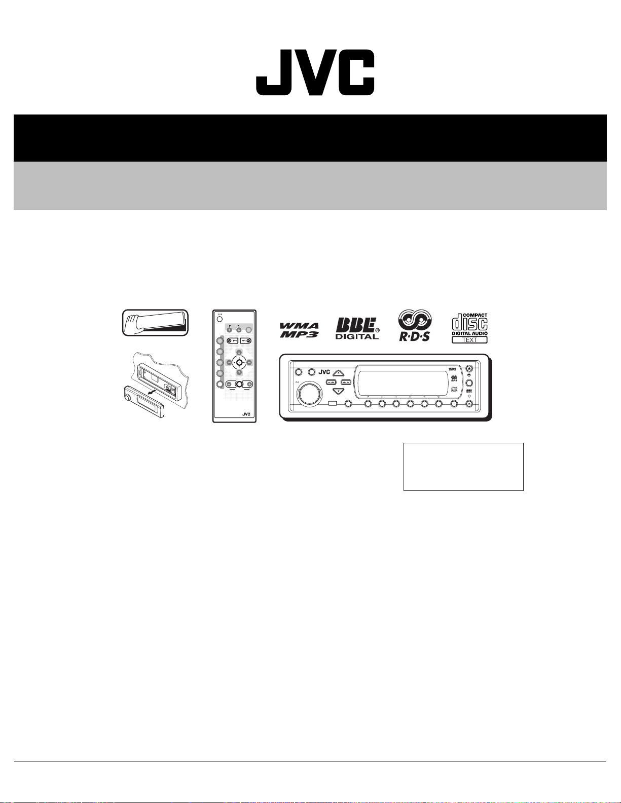
SERVICE MANUAL
CD RECEIVER
KD-SH9101, KD-SH9102,
KD-SH9103, KD-SH9104
ATT
Detachable
ANGLE
CD
DAB
FM
PRESET
AM
CH
AUX SEL
RM-RK100
EQ
DISC
PRESET
R D
DISC
VOLUME
SRC
D
DISP
ATT
MOSFET
SEL
KD-SH9101
T/P
3456 M21
MODE
Area Suffix
E ------ ContinentalEurope
EX --------- Central Europe
TABLE OF CONTENTS
1 Precautions . . . . . . . . . . . . . . . . . . . . . . . . . . . . . . . . . . . . . . . . . . . . . . . . . . . . . . . . . . . . . . . . . . . . . . . . . . 1-3
2 SPECIFIC SERVICE INSTRUCTIONS. . . . . . . . . . . . . . . . . . . . . . . . . . . . . . . . . . . . . . . . . . . . . . . . . . . . . . 1-5
3 Disassembly method . . . . . . . . . . . . . . . . . . . . . . . . . . . . . . . . . . . . . . . . . . . . . . . . . . . . . . . . . . . . . . . . . . 1-6
4 Adjustment. . . . . . . . . . . . . . . . . . . . . . . . . . . . . . . . . . . . . . . . . . . . . . . . . . . . . . . . . . . . . . . . . . . . . . . . . . 1-30
5 TROUBLESHOOTING . . . . . . . . . . . . . . . . . . . . . . . . . . . . . . . . . . . . . . . . . . . . . . . . . . . . . . . . . . . . . . . . . 1-33
COPYRIGHT © 2003 VICTOR COMPANY OF JAPAN, LIMITED
No.49841B
2003/11
Page 2
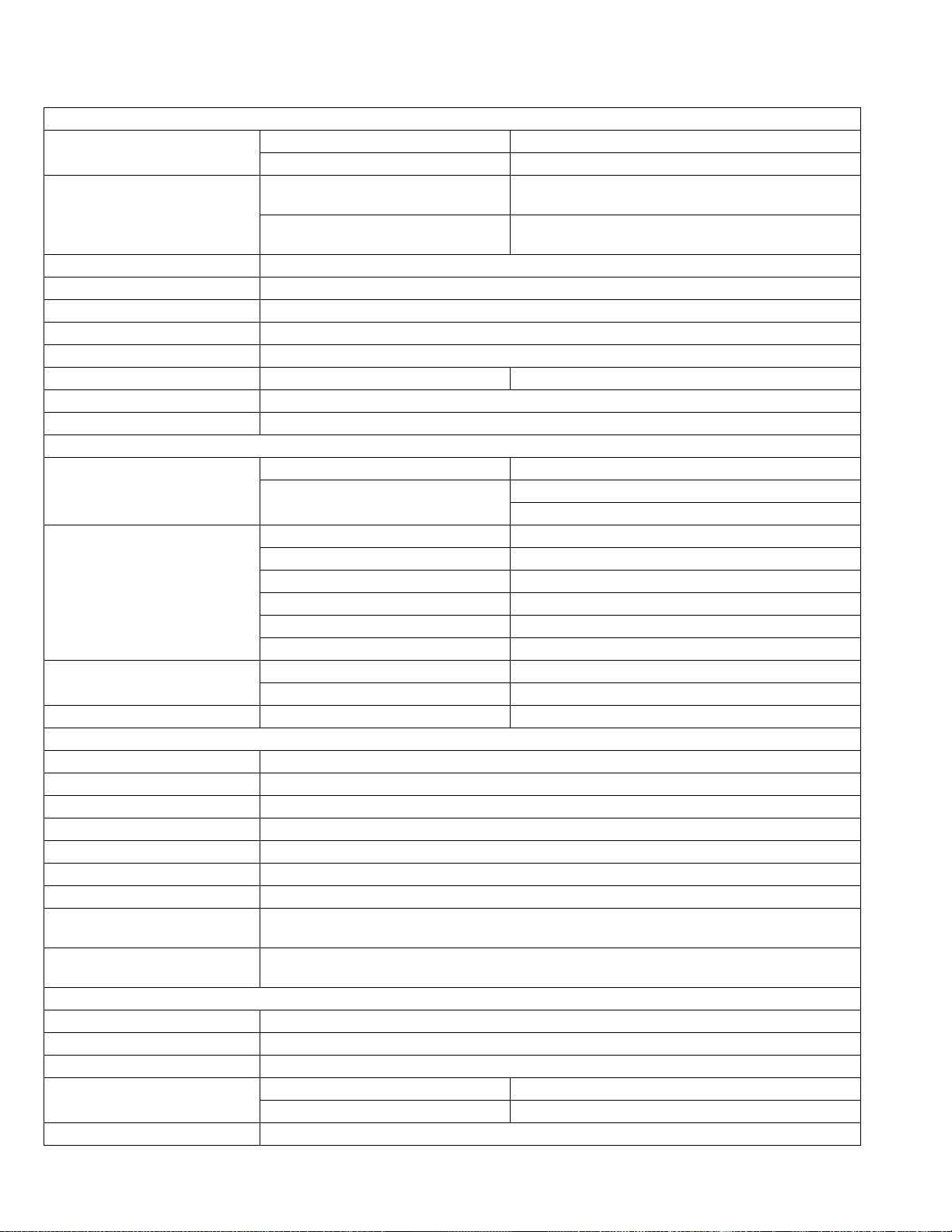
SPECIFICATION
AUDIO AMPLIFIER SECTION
Maximum Power Output
Continuous Power Output (RMS)
Load Impedance 4Ω (4Ω to 8Ω allowance)
Equalizer Control Range Frequencies: 60 Hz, 150 Hz, 400 Hz, 1 kHz, 2.4 kHz, 6 kHz, 12 kHz
Level ±10 dB
Frequency Response 40 Hz to 20 000 Hz
Signal-to-Noise Ratio 70 dB
Line-In Level/Impedance LINE IN 1.5 V/20 kΩ load
Line-Out Level/Impedance 4.0 V/20 kΩ load (full scale)
Output Impedance 1 kΩ
Frequency Range
[FM Tuner]
[MW Tuner]
[LW Tuner] Sensitivity 50 µV
Type Compact disc player
Signal Detection System Non-contact optical pickup (semiconductor laser)
Number of channels 2 channels (stereo)
Frequency Response 5 Hz to 20 000 Hz
Dynamic Range 98 dB
Signal-to-Noise Ratio 102 dB
Wow and Flutter Less than measurable limit
MP3 (MPEG Audio Layer 3) Max.
Bit rate
WMA (Windows Media
Max. Bit rate
Power Requirement Operating Voltage: DC 14.4 V (11 V to 16 V allowance)
Grounding System Negative ground
Allowable Operating Temperature 0°C to +40°C
Dimensions (W × H × D)
Mass 1.8 kg (excluding accessories)
Design and specifications are subject to change without notice.
(R)
Audio)
Front 50 W per channel
Rear 50 W per channel
Front
Rear
TUNER SECTION
FM 87.5 MHz to 108.0 MHz
AM
Usable Sensitivity 11.3 dBf (1.0µV/75Ω)
50 dB Quieting Sensitivity 16.3 dBf (1.8µV/75Ω)
Alternate Channel Selectivity (400 kHz) 65 dB
Frequency Response 40 Hz to 15 000 Hz
Stereo Separation 30 dB
Capture Ratio 1.5 dB
Sensitivity 20 µV
Selectivity 35 dB
CD PLAYER SECTION
320 Kbps
192 Kbps
GENERAL
Installation Size: 182 mm × 52 mm × 161 mm
Panel Size: 188 mm × 58 mm × 17 mm
19 W per channel into 4Ω, 40 Hz to 20 000 Hz at no more
than 0.8% total harmonic distortion.
19 W per channel into 4Ω, 40 Hz to 20 000 Hz at no more
than 0.8% total harmonic distortion.
(MW) 522 kHz to 1 620 kHz
(LW) 144 kHz to 279 kHz
1-2 (No.49841B)
Page 3
1.1 Safety Precautions
SECTION 1
Precautions
!
!
Burrs formed during molding may be left over on some parts of the chassis. Therefore,
pay attention to such burrs in the case of preforming repair of this system.
Please use enough caution not to see the beam directly or touch it in case of an
adjustment or operation check.
(No.49841B)1-3
Page 4
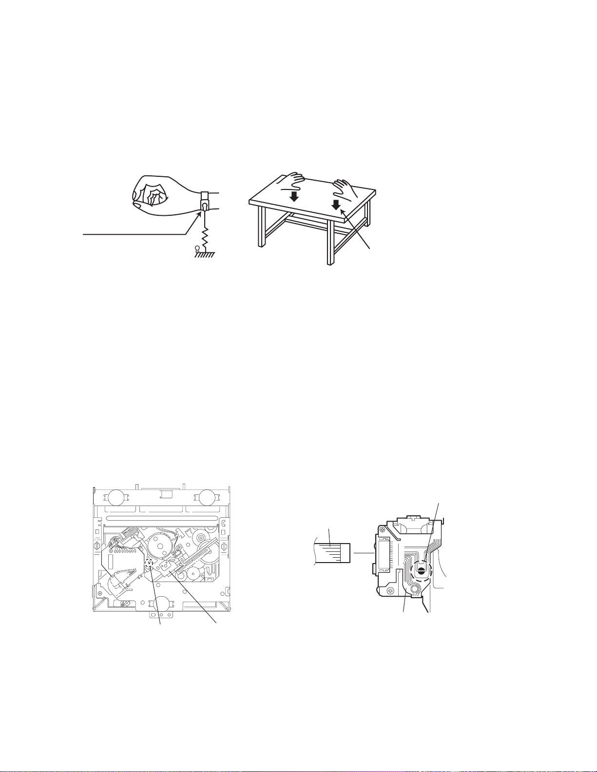
1.2 Preventing static electricity
Electrostatic discharge (ESD), which occurs when static electricity stored in the body, fabric, etc. is discharged, can destroy the laser
diode in the traverse unit (optical pickup). Take care to prevent this when performing repairs.
1.2.1 Grounding to prevent damage by static electricity
Static electricity in the work area can destroy the optical pickup (laser dio de) in devices such as CD players.
Be careful to use proper grounding in the area where repairs are being performed.
(1) Ground the workbench
Ground the workbench by laying conductive material (such as a conductive sh eet) or an iron plate over it before placing the
traverse unit (optical pickup) on it.
(2) Ground yourself
Use an anti-static wrist strap to release any static electricity built up in your body.
(caption)
Anti-static wrist strap
1M
Conductive material
(conductive sheet) or iron plate
(3) Handli ng the optical pickup
• In order to maintain quality during transpo rt and before installation, bo th sides of the laser diode on the replacement optical
pickup are shorted. After replacement, return the shorted parts to their original condition.
(Refer to the text.)
• Do not use a tester to check the condition of the laser diode in the optical pickup. The tester's internal power source can easily
destroy the laser diode.
1.3 Handling the traverse unit (optical pickup)
(1) Do not subject the trav erse unit (optical pickup) to strong shocks, as it is a sensitive, complex unit.
(2) Cut off the shorted part of the flexible cable using nippers, etc. after replacing the optical pickup. For specific details, refer to the
replacement procedure in the text. Remove the anti-static pin when replacing the traverse unit. Be careful not to take too long a
time when attaching it to the connector.
(3) Handle the flexible cable carefully as it may break when subjected to strong force.
(4) It is not possible to adju st the semi-fixed resistor that adjusts the laser power. Do not turn it.
1.4 Attention when traverse unit is decomposed *Please refer to "Disassembly method" in the text for the CD pickup unit.
• Apply solder to the short land before the flexible wire is disconnected from the connector on the CD pickup unit.
(If the flexible wire is disconnected without applying solder, the CDpickup may be destroyed by static electricity.)
• In the asse mbly, be sure to remove solder from the short land after connecting the flexible wire.
Short-circuit point
(Soldering)
Flexible wire
1-4 (No.49841B)
Short-circuit point
Pickup
Pickup
Page 5

SECTION 2
SPECIFIC SERVICE INSTRUCTIONS
This service manual does not describe SPECIFIC SERVICE INSTRUCTIONS.
(No.49841B)1-5
Page 6
SECTION 3
Disassembly method
3.1 Main body section
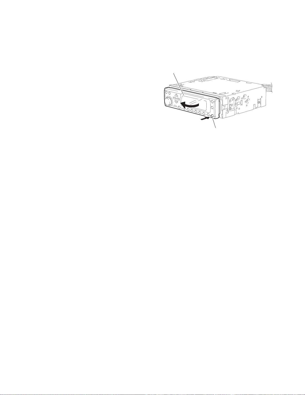
3.1.1 Removing the front panel assembly
(See Fig.1)
(1) Push the detach button in the lower right part of the front
panel assembly.
(2) Remove the front panel assembly in the direction of the ar-
row.
Front panel assembly
Detach button
Fig.1
1-6 (No.49841B)
Page 7
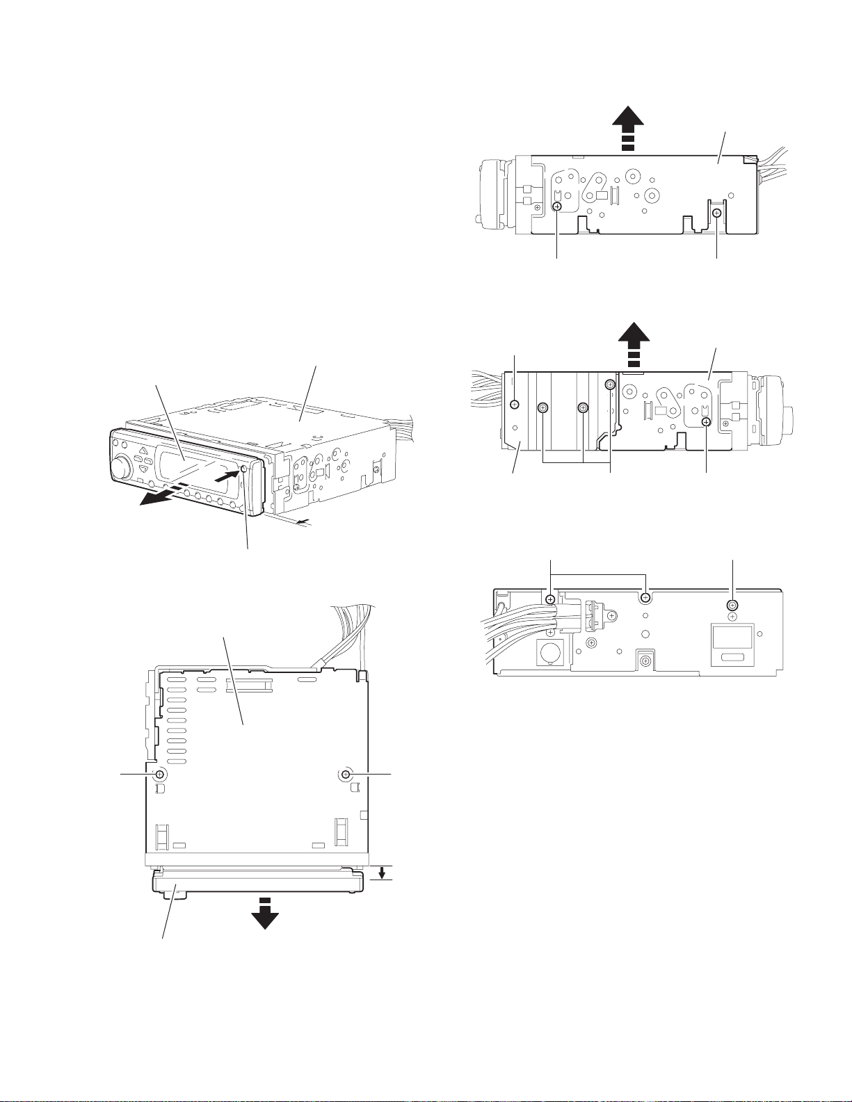
3.1.2 Removing the top chassis
(See Figs.2 to 6)
• Turn on power.
(1) Push the eject button in the upper right part of the front pan-
el assembly to move the front panel assembly as shown in
Fig.2 and turn off power.
(2) Remove th e two screws A attaching the top chassis from
the top side of the main body. (See Fig.3.)
(3) Remove the three screws B attaching the top chassis from
the both sides of the main body. (See Figs.4 and 5.)
(4) Remove the screw C and three screws D attaching the heat
sink from the left side of the main body. (See Fig.5.)
(5) Remove the two screws E an d screw F attaching the top
chassis from the back side of the main body. (See Fig.6.)
(6) Move the top chassis upward and remove it with the CD
mechanism assembly. The connector CN501 on the CD
mechanism assembly is disconnected from the connector
CN981 on the main board.
Top chassis
Front panel assembly
C
Top chassis
BB
Fig.4
Top chassis
Heat sink
Fig.5
Eject button
Fig.2
Top chassis
E
Fig.6
AA
BD
F
Front panel assembly
Fig.3
(No.49841B)1-7
Page 8
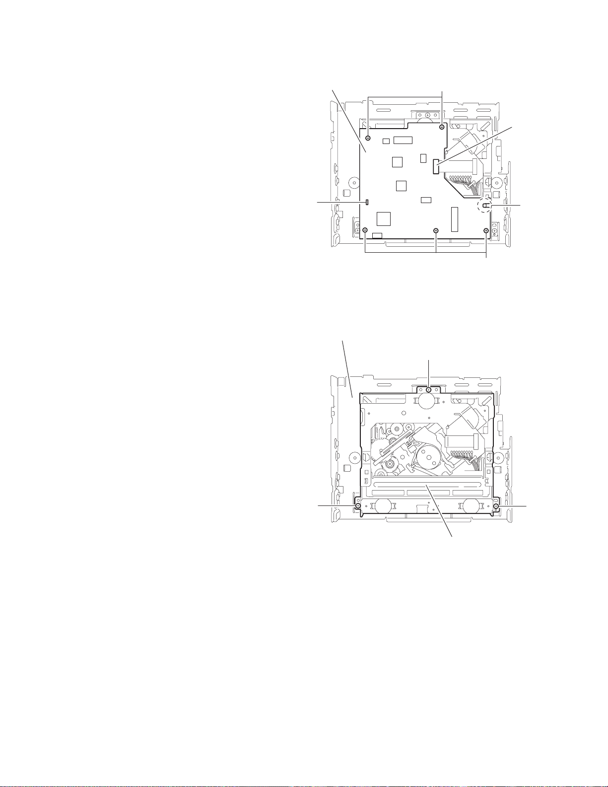
3.1.3 Removing the mecha control board
(See Fig.7)
• Prior to performing the foll owing procedures, remove the top
chassis.
(1) Disconnect the card wire from the connector CN601 on the
mecha control board.
(2) Remove the five screws G attaching the mecha control
board.
(3) Release the joints a and b, remove the mecha control
board.
Mecha control board
G
CN601
3.1.4 Removing the CD mechanism assembly
(See Fig.8)
• Prior to performing the followi ng procedure, remove the top
chassis.
(1) Remove the three screws H from the inside of the top chas-
sis and remove the CD mechanism assembly.
a
Top chassis
b
G
Fig.7
H
1-8 (No.49841B)
HH
CD mechanism assembly
Fig.8
Page 9
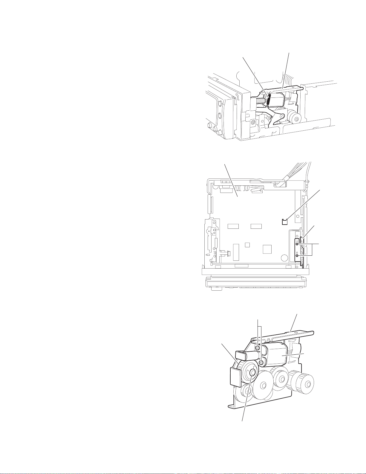
3.1.5 Removing the motor assembly
(See Figs.9 to 11)
• Prior to performing the following procedures, remove the top
chassis.
(1) Remove the spring from the motor bracket. (See Fig.9.)
(2) Disconnect the wire from the connector CN982 on the main
board. (See Fig.10.)
(3) Remove the two screws J attaching the motor bracket.
(See Fig.10.)
(4) Remove the washer attaching the clutch assembly and pull
out the clutch assembly from the shaft. (See Fig.11.)
(5) Remove the two screws K attaching the motor assembly to
the motor bracket. (See Fig.11.)
Main board
Spring
Motor braket
Fig.9
CN982
Clutch assembly
Motor braket
J
Fig.10
Motor braket
K
Motor assembly
Washer
Fig.11
(No.49841B)1-9
Page 10

3.1.6 Removing the main board
A
A
(See Figs.12 to 16)
• Prior to performing the foll owing procedures, remove the top
chassis and motor assembly.
(1) Disconne ct the flexible wires from the connectors CN703
and CN991 on the main board respectively. (See Fig.12.)
(2) Move the front bracket backward until it stops.
(3) Remove the four screws L attaching the arm brackets (L)
and (R). Move the arm brackets (L) and (R) from the rod
gear. (See Fig.12.)
(4) Remove the rod gear.
(5) Remove the screw M attaching the rear panel to the bottom
cover from the back side of the main body. (See Fig.14.)
(6) Remove th e three screws N attaching the mai n board and
move the main board backwards to release the two joints
c. (The main board will be removed with the rear panel and
rear heat sink) (See Figs.12 and 15.)
(7) Remove the screw P and Q attaching the rear heat sink.
(See Fig.16.)
(8) Remove the three screws R and screw S attaching the rear
panel, then remove the main board. (See Fig.16.)
Rear panel
M
Bottom cover
Fig.14
Joint c
Main board
Joint c
rm
brackets (L)
L
CN703
rm brackets (R)
NN
Main board
Arm
brackets (R)
L
Rod gear
CN991
Fig.12
Arm brackets (L)
M
R
Rear panel
S
Fig.15
P
Q
Rear heat sink
Fig.16
1-10 (No.49841B)
Main board
Rod gear
Fig.13
Page 11
3.1.7 Removing the lifter switc h bo ar d
(See Fig.17)
• Prior to perfo rming the following procedure, remove the top
chassis, motor assembly and main board.
(1) Remove the two screws T attaching the lifter switch board
to the bottom chassis.
Lifter switch board
Fig.17
Bottom chassis
T
(No.49841B)1-11
Page 12

3.1.8 Removing the lifter board
r
f
(See Figs.18 to 24)
• Prior to performing the foll owing procedures, remove the top
chassis and front panel assembly.
• Remove the four screws U attaching the front bracket on the
both sides of the main body. (See Figs.19 and 20.)
• Push the pin of the joint d on the front side of the front bracket
to release the detach lever. (See Fig.21. )
• Remove the screw V attaching the connector cover in the rear
side of the front bracket. (See Fig.22.)
• Release the two joints f while pushing them from the f ront side,
and then move the connector cover in the direction of the arrow
and release the eight joints e. (See Figs.22 and 23.)
• Remove the two screws W attaching the lifter board from the
front side of the main body. (See Fig.24.)
(1) Disconnect the flexible wire from the connector CN991 on
the main board. (See Fig.18.)
Front bracket
U
Main board
CN991
Fig.18
Front bracket
Front bracket
Joint f
V
Connector cover
Joint e
Fig.20
Fig.21
Joint e
Joint d
Datch leve
Joint e
Joint
Front bracket
1-12 (No.49841B)
Fig.19
U
Joint e
Joints e
Front bracket
Fig.22
Page 13

Lifter board
Connector cover
Fig.23
Fig.24
W
(No.49841B)1-13
Page 14

3.1.9 Removing the front board
(See Figs.25 to 28)
• Prior to performing the following procedures, remove the front
panel assembly.
(1) Remove the six screws X attaching the rear panel to the
front panel assembly. (See Fig.25.)
(2) Pull ou t the volume knob from the front side of the front
panel assembly. (See Fig.26.)
(3) Release the ten joints g of the front panel and the rear pan-
el. (See Fig.27.)
(4) Take out the front board from the front panel assembly.
(See Fig.28.)
Front panel assembly
XX
Rear panel
Volume knob
XX
Fig.25
Joints
g
Joints g
Fig.26
Rear panel
Joints g
Joints g
Fig.27
Front board
1-14 (No.49841B)
Fig.28
Page 15

3.2 CD Mechanism section
A
3.2.1 Removing the top cover
(See Figs.1 and 2)
(1) Remove the four screws A on the both side of the body.
(2) Lift the front side of the top cover an d move the top cover
backward to release the two joints a.
Top cover
Joints a
A
Joints a
A
Fig.1
Fig.2
Top cover
(No.49841B)1-15
Page 16

3.2.2 Removing the connector board
(See Figs.3 to 5)
CAUTION:
Before disconnecting the flexible wire from the pickup, solder
the short-circuit point on the pickup. No observance of this instruction may cause damage of the pickup.
(1) Remove the screw B fixing the connector board.
(2) Solder the short-circuit point on the pickup.
(3) Disconnect the flexible wire from the pickup.
(4) Move th e connector board in the direction of the arrow to
release the two joints b.
(5) Unsolder the wires on the connector board if necessary.
CAUTION:
Unsolder the short-circuit point after reassembling.
B
Connector board
Flexible wire
Wires
Joints b
Short-circuit point
Fig.3
Short-circuit point
(Soldering)
Pickup
Flexible wire
Frame
Pickup
Fig.4
B
Connector board
Fig.5
1-16 (No.49841B)
Page 17

3.2.3 Removing the DET switch
(See Figs.6 and 7)
(1) Exten d the two tabs c of the feed sw. hol der and pull out
the switch.
(2) Unsolder the DET switch wire if necessary.
DET
switch
Connector
board
Pickup
Fig.6
DET switch
Tab c
Tab c
DET switch wire
Feed sw. holder
Fig.7
(No.49841B)1-17
Page 18

3.2.4 Removing the chassis unit
r
(See Figs.8 and 9)
• Prior to performing the followi ng procedure, remove the top
cover and connector board.
(1) Remove the two suspension springs (L) and (R) attaching
the chassis unit to the frame.
CAUTION:
• The shape of the suspension spring (L) and (R) are different. Handle them with care.
• When reassembling, make sure that the three shafts
on the underside of the chassis unit are inserted to the
dampers certainly.
Suspension spring (R)
Chassis unit
Suspension spring (L)
Frame
Suspension spring (R)
Chassis unit
Shafts
Damper
Damper
Suspension spring (L)
Fig.8
Shaft
Dampe
Frame
Fig.9
1-18 (No.49841B)
Page 19

3.2.5 Removing the clamper assembly
(See Figs.10 and 11)
• Prior to perfo rming the following procedure, remove the top
cover.
(1) Remove the clamper arm spring.
(2) Move the clamper assembly in the direction of the arrow to
release the two joints d.
Clamper arm
spring
Joint d
Joint d
Clamper assembly
Fig.10
Clamper arm spring
Chassis rivet
assembly
Joint d
Clamper assembly
Chassis rivet assembly
Joint d
Fig.11
(No.49841B)1-19
Page 20

3.2.6 Removing the loading / feed motor assembly
(See Figs.12 and 13)
• Prior to performing the followi ng procedure, remove the top
cover, connector board and chassis unit.
(1) Remove the screw C and move the loading / feed motor as-
sembly in the direction of the arrow to remove it from the
chassis rivet assembly.
(2) Disconnect the wire from the loading / feed motor assembly
if necessary.
CAUTION:
When reassembling, connect the wire from the loadin g /
feed motor assembly to the flame as shown in Fig.12.
Loading / feed motor assembly
Fig.12
Loading / feed motor assembly
C
Fig.13
1-20 (No.49841B)
Page 21

3.2.7 Removing the pickup unit
r
(See Figs.14 to 18)
• Prior to perfo rming the following procedure, remove the top
cover, connector board and chassis unit.
(1) Remove the screw D and pull out the pu. shaft holder from
the pu. shaft.
(2) Remove the screw E attaching the feed sw. holder.
(3) Move the part e of the pickup unit upward with the pu. shaft
and the feed sw. holder, then release the joint f of the feed
sw. holder in the direction of the arrow. The joint g of the
pickup unit and the feed rack is released, and the feed sw.
holder comes off.
(4) Remove the pu. shaft from the pickup unit.
(5) Remove the screw F attaching the feed rack to the pickup
unit.
Part e
Feed rack
Pickup unit
Feed sw. holder
Fig.15
3.2.8 Reattaching the pickup unit
(See Figs.14 to 17)
(1) Reattach the feed rack to the pickup unit using the screw F.
(2) Reattach the feed sw. holder to the feed rack while setting
the joint g to the slot of the feed rack and setting the joint f
of the feed rack to the switch of the feed sw. holder correctly.
(3) As the feed sw. holder is temporarily attached to the pickup
unit, set to the gear of the joint g and to the bending part of
the chassis (joint h) at a time.
CAUTION:
Make sure that the part i on the underside of the feed
rack is certainly inserted to the slot j of the change lock
lever.
(4) Reattach th e feed sw. holder using the screw E.
(5) Reattach th e pu. shaft to the pickup unit. Reatta ch the pu.
shaft holder to the pu. shaft using the screw D.
Feed sw. holder
Joint f
Joint g
Feed sw. holder
Pickup unit
E
Part i
Slot j
F
Pu. shaft
Pickup unit
Joint f
Joint h
Fig.16
Feed rack
D
Pu. shaft holde
Pu. shaft
D
Pu. shaft holder
Pickup unit
Fig.14
Part e
E
Joint g
Feed rack
Fig.17
Pickup unit
Joint g
Joint f
Feed sw. holder
Fig.18
(No.49841B)1-21
Page 22

3.2.9 Removing the trigger arm
r
(See Figs.19 and 20)
• Prior to performing the followi ng procedure, remove the top
cover, connector board and clamper unit.
(1) Turn the trigger arm in the direction of the arrow to release
the joint k and pull out upward.
CAUTION:
When reassembling, insert the part m and n of the trigger arm into the part p and q at the slot of the chassis rivet assembly respectively and join the joint k at a time.
Chassis rivet assembly
Trigger arm
Chassis
rivet
assembly
Joint k
Trigger arm
Fig.19
Part p
Part q
Part m
Part n
3.2.10 Removing the top plate assembly
(See Fig.21)
• Prior to performing the followi ng procedure, remove the top
cover, connector board, chassis unit, and clamper assembly.
(1) Remove the screw H.
(2) Move the top plate assembly in the direction of the arrow to
release the two joints r.
(3) Unsolder the wire marked s if necessary.
H
Fig.20
Top plate assembly
Joints
s
Fig.21
1-22 (No.49841B)
Page 23

3.2.11 Removing the mode sw. / select lock arm
(See Figs.22 and 23)
• Prior to perfo rming the following procedure, remove the top
plate assembly.
(1) Bring up the mode sw. to release from the link plate (joint t)
and turn in the direction of the arrow to release the joint u.
(2) Unsolder the wire of the mode sw. marked s if necessary.
(3) Turn the select lock arm in the dire cti on of the arrow to re-
lease the two joints v.
(4) The select lock arm spring comes off the select lock arm at
the same time.
Link plate
Joint u
Fig.22
Joint t
Mode sw.
Select lock arm
s
Top plate
Select lock arm
Link plate
Select lock arm
Fig.23
Top plate
Hook w
Select lock
arm spring
Joints v
(No.49841B)1-23
Page 24

3.2.12 Reassembling the mode sw. / select lock arm
(See Figs.24 to 26)
REFERENCE:
Reverse the above removing procedure.
(1) Reattach the select lock arm spring to the top plate and set
the shorter end of the select lock arm spring to the hook w
on the top plate.
(2) Set the other longer end of the select lock arm spring to the
boss x on the underside of the select lock arm, and join the
select lock arm to the slots (joint v). Turn the select lock
arm as shown in the figure.
(3) Reattach the mode sw. while setting the part t to the first
peak of the link plate gear, and join the joint u.
CAUTION:
When reattaching the mode sw., check if the points y
and z are correctly fitted and if each part operates properly.
Select lock arm spring
Hook w
Joint v
Joint v
Select lock arm
Boss x
Fig.24
Joint t
Point y
Link plate
Point z
Link plate
Fig.25
Mode sw.
Select
lock arm
Joint t
Joint u
Fig.26
1-24 (No.49841B)
Page 25

3.2.13 Removing the select arm R / link plate
(See Figs.27 and 28)
• Prior to perfo rming the following procedure, remove the top
plate assembly.
(1) Bri ng up the select arm R to release from the link plate
(joint a') and turn as shown in the figure to release the two
joints b' and joint c'.
(2) Move the link plate in th e direction of the arrow to release
the joint d'. Remove the link plate spring at the same time.
REFERENCE:
Before removing the link plate, remove the mode sw..
Select arm R
Joint b'
Link plate spring
Joint c'
Joint a'
Link plate
Joint b'
Fig.27
Joint r
3.2.14 Reattaching the Select arm R / link plate
(See Figs.29 and 30)
REFERENCE:
Reverse the above removing procedure.
(1) Reattach th e link plate spring.
(2) Reattach the li nk plate to the link pla te spri ng while j oini ng
them at joint d'.
(3) Reattach the joint a' of the select arm R to the first peak of
the link plate while joining the two joints b' with the slots.
Then turn the select arm R as shown in the figure. The top
plate is joined to the joint c'.
CAUTION:
When reattaching the sele ct arm R, check if the points e'
and f' are correctly fitted and if each part operates properly.
Top plate
Select arm R
Joint b'
Joint d'
Link plate
Fig.28
Link plate spring
Joint c'
Joint d'
Joint b'
Joint a'
Fig.29
Joint a'
Point e'
Link plate
Point f'
Fig.30
(No.49841B)1-25
Page 26

3.2.15 Removing the loading roller assembly
(See Figs.31 to 33)
• Prior to performing the following procedure, remove the
clamper assembly and top plate assembly.
(1) Push inw ard the loading roller assembly on the gear side
and detach it upward from the slot of the joint g' of the lock
arm rivet assembly.
(2) Detach the loading roller assembly from the slot of the joint
h' of the lock arm rivet assembly.
Roller guide
spring
Part k'
Loading roller assembly
Loading roller assembly
The roller guide comes off the gear section of the loading
roller assembly.
Remove the roller guide and the HL washer from the shaft
of the loading roller assembly.
(3) Remove the screw J attaching the lock arm rivet assembly.
(4) Push th e shaft at the joint i' of the lock arm rivet assembly
inward to release the lock arm rivet assembly from the slot
of the L side plate.
(5) Extend the lock arm rivet assembl y outward and release
the joint j' from the boss of the chassis rivet assembly. The
roller guide springs on both sides come off at the same
time.
CAUTION:
When reassembling, reattach the left and right roller
guide springs to the lock arm rivet assembly before reattaching the lock arm rivet assembly to the chassis rivet
assembly. Make sure to fit the part k' of the roller guide
spring inside of the roller guide. (Refer to Fig.34.)
Roller guide
HL washer
Loading roller assembly
Roller guide
Chassis rivet assembly
J
Roller guide
spring
Fig.32
Boss
L side plate
Roller guide spring
Joint h'
Roller guide spring
Loading roller assembly
1-26 (No.49841B)
Joint g'
Lock arm rivet assembly
Fig.31
Roller guide spring
Roller guide spring
Lock arm rivet assembly
Lock arm rivet assembly
Joint j'
Joint i'
Fig.33
Roller guide
HL washer
Roller shaft assembly
Loading roller
Roller guide spring
Fig.34
Page 27

3.2.16 Removing the loading gear 5, 6 and 7
(See Figs.35 and 36)
• Prior to perfo rming the following procedure, remove the top
cover, chassis unit, pickup unit and top plate assembly.
(1) Remove the screw K atta ching the loading gear bracket.
The loading gear 6 and 7 come off the loading gear bracket.
(2) Pull out the loading gear 5.
K
Loading gear 5
Loading gear bracket
K
Loading gear 6
Loading gear 5
Loading gear 3
Fig.35
Loading gear bracket
Loading gear 6
Loading gear 7
Fig.36
(No.49841B)1-27
Page 28

3.2.17 Removing the gears
(See Figs.37 to 40)
• Prior to performing the followi ng procedure, remove the top
cover, chassis unit, top plate assembly and pickup unit.
• Pull out the loading gear 3. (See Fig.35.)
(1) Pull out the feed gear.
(2) Move the load ing pl ate assembly i n the dire ctio n of the ar-
row to release the L side plate from the two slots m' of the
chassis rivet assembly. (See Fig.37.)
(3) Detach the loading pla te assembly upward from the chas-
sis rivet assembly while releasing the joint n'. Remove the
slide hook and loading plate spring from the loading plate
assembly.
(4) Pull out the loading gear 2 and remove the change lock le-
ver.
(5) Remove the E ring and washer attaching the change ge ar
2.
(6) The change gear 2, change gear spring and adjusting
washer come off.
(7) Remov e the loading gear 1.
(8) Move the change plate rivet assembly in the direction of the
arrow to release from the three shafts of the chassis rivet
assembly upward. (See Fig.38.)
(9) Detach the loading gear plate rivet assembly from the shaft
of the chassis rivet assembly upward while releasing the
joint p'. (See Figs.38 and 40.)
(10) Pull out the loading gear 4.
Change plate
rivet assembly
Shafts
E ring
Loading plate assembly
Loading plate spring
Joint p'
Loading gear 4
Loading gear plate
rivet assembly
Shaft
Loading gear 2
Loading gear 1
Chassis rivet assembly
Change gear 2
Fig.38
Joint n'
Slide hook
Feed gear
Fig.37
Slot m'
L side plate
Loading plate assembly
Joint n'
Slot m'
Chassis rivet assembly
Chassis rivet assembly
E ring
Washer
Change gear 2
Change gear
spring
Adjusting
washer
Change plate
rivet assembly
L side plate
Slot m'
Slot m'
Fig.39
Loading gear 1
Loading gear 2
Change lock lever
Loading gear 4
1-28 (No.49841B)
Chassis rivet assembly
Loading gear plate rivet
assembly
Fig.40
Page 29

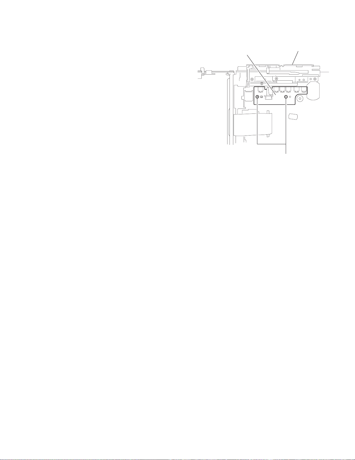
3.2.18 Removing the turn table / spindle motor
(See Figs.41 and 42.)
• Prior to perfo rming the following procedure, remove the top
cover, connector board, chassis unit and clamper assembly.
(1) Remove the two screws L a ttaching the spindle motor as-
sembly through the slot of the turn table on top of the body.
(2) Unsolder the wire on the connector board if necessary.
Turn table
L
Fig.41
L
Turn table
Spindle motor
Fig.42
(No.49841B)1-29
Page 30

SECTION 4
Adjustment
4.1 Adjustment method Test instruments required for adjustment
(1) Digital oscilloscope (100MHz)
(2) AM Standard sign al generator
(3) FM Standard signal generator
(4) Stereo modulator
(5) Electric voltmeter
(6) Digital tester
(7) Tracking offset meter
(8) Test Disc JVC :CTS-100 0
(9) Extension ca ble for check
EXTSH002-22P × 1
Standard volume position
Balance and Bass &Treble volume : lndication"0"
Loudness : OFF
How to connect the extension cable for adjusting
Caution:
Be sure to attach the heat sink and rear bracket onto the power amplifier IC and regulator IC respectively, before supply the power.
If voltage is applied without attaching these parts, the power amplifier IC and regulator IC will be destroyed by heat.
Standard measuring conditions
Power supply voltage DC14.4V(11 to 16V)
Load impedance 20KΩ(2 Speakers connection)
Output Level Line out 2.0V (Vol. MAX)
Frequency Band
FM1 87.5MHz to 108.0MHz
AM (MW) 522kHz to 1620kHz
AM (LW) 144kHz to 279kHz
Dummy load
Exclusive dummy load should be used for AM,and FM. For FM
dummy load,there is a loss of 6dB between SSG output and
antenna input.The loss of 6dB need not be considered since
direct reading of figures are applied in this working standard.
The cardboard is cut in a suitable size.
uses for the insulation stand of mechanism.
Extension cable
EXTSH002-22P
4.2 Service mode
1-30 (No.49841B)
Page 31

When entering the service mode, "DATA CLEAR" is displayed without fail.
r
: Initial display
SEL
POWER
SOURCE
A
DATA_CLEAR
DISC+/-:CATEGORY
: SEEK UP
: SEEK DOWN
: DISC UP
: DISC DOWN
EPROM_CLEAR
NAME_CLEAR
CD_ERROR_CLEAR
CH_ERROR_CLEAR
SH_MECHA_ERROR_CLEAR
EPROM_CLEAR
NAME_CLEAR
CD_ERROR_CLEAR
CH_ERROR_CLEAR
SH_MECHA_ERROR_CLEAR
EPROM_CLEAR
NAME_CLEAR
CD_ERROR_CLEAR
CH_ERROR_CLEAR
SH_MECHA_ERROR_CLEAR
EPROM_CLEAR
NAME_CLEAR
CD_ERROR_CLEAR
CH_ERROR_CLEAR
SH_MECHA_ERROR_CLEAR
EPROM_CLEAR
NAME_CLEAR
CD_ERROR_CLEAR
CH_ERROR_CLEAR
SH_MECHA_ERROR_CLEAR
PICTURE_CLEAR
DSP_ERROR_CLEAR
PICTURE_CLEAR
DSP_ERROR_CLEAR
___NOW
___ERROR_CLEAR
SEL
*Letter turn on and off
(Turn on: 0.5sec, Turn off: 0.5sec)
___NOW
___NAME_CLEAR
SEL
*Letter turn on and off
(Turn on: 0.5sec, Turn off: 0.5sec)
___NOW
___CD_ERROR_CLEAR
SEL
*Letter turn on and off
(Turn on: 0.5sec, Turn off: 0.5sec)
___NOW
___CH_ERROR_CLEAR
SEL
*Letter turn on and off
(Turn on: 0.5sec, Turn off: 0.5sec)
___NOW
___SH_MECHA_ERROR_CLEAR
SEL
*Letter turn on and off
(Turn on: 0.5sec, Turn off: 0.5sec)
___NOW
___PICTURE_CLEAR
SEL
*Letter turn on and off
(Turn on: 0.5sec, Turn off: 0.5sec)
___NOW
___DSP_ERROR_CLEAR
SEL
*Letter turn on and off
(Turn on: 0.5sec, Turn off: 0.5sec)
EPROM all clear & Flash ROM all clear
(Following all contents are cleared.)
Execute by "SEL" key
Normal
display
EPROM (DISC/LINE NAME) clear
Execute by "SEL" key
Normal
display
EPROM (CD ERROR) clear
Execute by "SEL" key
Normal
display
EPROM (CH ERROR) clear
Execute by "SEL" key
Normal
display
EPROM (SH DOOR MECHA ERROR) clear
Execute by "SEL" key
Normal
display
Flash ROM (all PICTURE) clear
Execute by "SEL" key
Normal
display
Flash ROM (all DSP retry count number) clea
Execute by "SEL" key
Normal
display
RUNNING_MODE
DISC+/-:FUNCTION
B
C
RUNNING_CD
RUNNING_SH_MECHA
RUNNING_CD
RUNNING_SH_MECHA
RUNNING_CD
COUNT :
ERROR :
SEL
RUNNING_SH_MECHA
COUNT :
ERROR :
SEL
CD running mode (SH mecha open)
Running number
CD error during running mode
by error code chart
Door mecha running mode (No retry action)
Running number
Door error during running mode
by error code chart
(No.49841B)1-31
Page 32

B
C
CD_DATA_READ
DISC+/-:FUNCTION
ERROR_READ
DISC+/-:FUNCTION
ADJ_NOW
ADJ_INT
OTHERS
ADJ_NOW
ADJ_INT
OTHERS
ADJ_NOW
ADJ_INT
OTHERS
CD_ERROR_READ
CH_ERROR_READ
SH_MECHA_ERROR_READ
CD_ERROR_READ
CH_ERROR_READ
SH_MECHA_ERROR_READ
ADJ_NOW
FEB__ ____TEB__
FGA__ ____TGA__
SEL
FEO__ ____RFG__
TEO__
ADJ_INT
FEB__ ____TEB__
FGA__ ____TGA__
SEL
FEO__ ____RFG__
TEO__
OTHERS
IOP__TEMP____I T
IOP__INT__
SEL
TEMP__MAX__
P_TOTAL_ H
TOTAL_ERROR :
E1_ _____2_
E2_ _____3_
SEL
E3_ _____4_
1__ 5_
TOTAL_ERROR :
E1_ _____2_
E2_ _____3_
SEL
E3_ _____4_
1__ 5_
CD data display
Hex. code display
Total running time display
(Four figures (to 9999), hour only, omit)
CD error display
Total error number
Display by error code chart
CH error display
Total error number
Display by error code chart
VERSION
MAIN_V
CD_V
CH_V
A
CD_ERROR_READ
CH_ERROR_READ
SH_MECHA_ERROR_READ
CD_ERROR_READ
CH_ERROR_READ
SH_MECHA_ERROR_READ
E1_
E2_
SEL
E3_
1__
INIT_RETRY____TOTAL_
INIT_RETRY_NG_TOTAL_
SEL
SH door mecha error display
Display by error code chart
DSP initial setting data error
Retry total number of initial setting
Error number: NG after retry two times
(First transmit NG Retry first transmit NG
Second transmit NG : 1 count)
1-32 (No.49841B)
Page 33

TROUBLESHOOTING
5.1 Flow of functional operation untill TOC read (CD)
SECTION 5
When the pickup correctly moves
to the inner area of the disc
$82
Microprocessor
commands
FMO
TC94A14FA "40"
FEED MOTOR
+TERMINAL
IC681 "17"
REST SW
When correctly focused
FEO
TA2157 "15"
$83
$81
Focus Servo Loop ONo
v
3.3V
Hi-Z
0V
6V
4V
2V
OFF
ON
Pickup feed to the inner area
2.2V
RF signal eye-pattern
remains closed
RF signal eye-pattern
opens
Power ON
Set Function CD
Disc inserted
YES
Laser emitted
Focus search
Disc rotates
n
Tracking loop closed
TOC read out
YES
When the laser diode correctly
emits
Microprocessor
commands
SEL
TC94A14FA "38"
LD
CN601 "10"
"No disc"
display
When the disc correctly rotates
Microprocessor
commands
DMO
TC94A14FA "41"
Spindle
motor(-)
IC681 "16"
$84 $86 $ A200
Acceleration Servo CLV
0.5 Sec 0.5 Sec
$84
Rough
Servo
3.3V
0V
4V
0V
3.3V
2.2V
0V
6V
3.2
2V
Jump to the first track
Play
Tracking Servo Loop ON
RF signal
Rough Servo Modev
CLV Servo Mode
(Program Area)
CLV Servo Mode
(Lead-In Area;
Digital :0)
(No.49841B)1-33
Page 34

5.2 Feed section
Is the voltage output at
IC621 pin "40" 5V or 0V?
Is 4V present at both
sides of the feed motor?
Check the feed motor.
5.3 Focus section
5.4 Spindle section
YES
YES
NO YES NO
Is the wiring for IC621
pin "40"?
NO
Is 3.3V present at IC681
pin "6"?
YES
Check the vicinity of
IC621.
NO
Is 6V or 2V present at
IC681 "16" and "17"?
YES
Check the feed motor
connection wiring.
NO
Check IC681.
When the lens is
moving:
4V
Does the S-search
waveform appear at
IC681 pins "13" and "14"?
NO
YES
Check the circuits in
the vicinity of IC681
pins "13","14"and"1".
YES
Check the pickup and
its connections
Check CD 8V
and 5V.
Is the disk rotated?
YES
Does the RF signal
appear at IC601 pin "19"?
YES
Is the RF waveform at
IC601 pin "19" distorted?
YES
Proceed to the Tracking
section
5.5 Tracking section
When the disc is rotated
at first:
Is the tracking error signal
output at IC601 "11"?
NO
NO
NO
Approx. 1.2V
NO
Is 4V present at IC681
pins "15" and "16"?
Is 4V present at IC621
pins "41" ?
YES
Check the spindle motor
and its wiring
Check the circuits in the
vicinity of IC601 pin "19"
or the pickup
YES YES
Check the circuit in the
vicinity of IC601 pins
"2" to "7".
YES
Check the vicinity of
IC681.
Check the pickup and
its connections
NO
Check the circuits in
the vicinity of IC621
or IC621
1-34 (No.49841B)
YES
Check IC621.
Page 35

5.6 Maintenance of laser pickup
(1) Cleaning the pick up lens
Before you replace the pick up, please try to clean the lens
with a alcohol soaked cotton swab.
(2) Life of the laser diode
When the life of the laser diode has expired, the following
symptoms will appear.
• The level of RF output (EFM output: amplitude of eye
pattern) will be low.
5.7 Replacement of laser pickup
Turn off the power switch and,disconnect the
power cord from the ac outlet.
Replace the pickup with a normal one.(Refer
to "Pickup Removal" on the previous page)
Is RF output
1.0 0.4Vp-p?
NO
Replace it.
YES
O.K
(3) Semi-fi xed resistor on th e APC PC board
The semi-fixed resistor on the APC printed circuit board
which is attached to the pickup is used to adjust the laser
power.Since this adjustment should be performed to match
the characteristics of the whole optical block, do not touch
the semi-fixed resistor.
If the laser power is lower than the specified value, the laser diode is almost worn out, and the laser pickup should
be replaced. If the semi-fixed resistor is adjusted while the
pickup is functioning normally, the laser pickup may be
damaged due to excessive current.
Plug the power cord in,and turn the power on.
At this time,check that the laser emits for
about 3seconds and the objective lens moves
up and down.
Note: Do not observe the laser beam directly.
Play a disc.
Check the eye-pattern at RF test point.
Finish.
(No.49841B)1-35
Page 36

VICTOR COMPANY OF JAPAN, LIMITED
AV & MULTIMEDIA COMPANY MOBILE ENTERTAINMENT CATEGORY 10-1,1chome,Ohwatari-machi,Maebashi-city,371-8543,Japan
(No.49841B)
Printed in Japan
WPC
 Loading...