

Page 1
MA028200311
SERVICE MANUAL
CD RECEIVER
KD-S6060
Area suffix
E ----------- Continental Europe
LOUD
SEL
DISP
MO
8
7 9 10 12
11
RPT
RND
FM
CD
SSM
AM
SCMMODE
COMPACT
DIGITAL AUDIO
TABLE OF CONTENTS
1 PRECAUTION. . . . . . . . . . . . . . . . . . . . . . . . . . . . . . . . . . . . . . . . . . . . . . . . . . . . . . . . . . . . . . . . . . . . . . . . . 1-3
2 SPECIFIC SERVICE INSTRUCTIONS. . . . . . . . . . . . . . . . . . . . . . . . . . . . . . . . . . . . . . . . . . . . . . . . . . . . . . 1-5
3 DISASSEMBLY . . . . . . . . . . . . . . . . . . . . . . . . . . . . . . . . . . . . . . . . . . . . . . . . . . . . . . . . . . . . . . . . . . . . . . . 1-6
4 ADJUSTMENT . . . . . . . . . . . . . . . . . . . . . . . . . . . . . . . . . . . . . . . . . . . . . . . . . . . . . . . . . . . . . . . . . . . . . . . 1-24
5 TROUBLESHOOTING . . . . . . . . . . . . . . . . . . . . . . . . . . . . . . . . . . . . . . . . . . . . . . . . . . . . . . . . . . . . . . . . . 1-25
COPYRIGHT © 2003 VICTOR COMPANY OF JAPAN, LIMITED
No.MA028
2003/11
Page 2

SPECIFICATION
AUDIO AMPLIFIER SECTION
Maximum Power Output Front 45 watts per channel
Rear 45 watts per channel
Continuous Power Output (RMS) F ront 17 watts per channel into 4 Ω, 40 Hz to 20 000 Hz at no more than
0.8% total harmonic distortion.
Rear 17 watts per channel into 4 Ω, 40 Hz to 20 000 Hz at no more than
0.8% total harmonic distortion.
Load Impedance 4 Ω (4 Ω to 8 Ω allowance)
Tone Control Range Bass ±10 dB at 100 Hz
Treble ±10 dB at 10 kHz
Frequency Response 40 Hz to 20 000 Hz
Signal-to-Noise Ratio 70 dB
Line-Out Level/Impedance 2.0 V/20 kΩ load (full scale)
Output Impedance 1 kΩ
TUNER SECTION
Frequency Range FM 87.5 MHz to 108.0 MHz
AM (MW) 522 kHz to 1 620 kHz
(LW) 144 kHz to 279 kHz
[FM Tuner] Usable Sensitivity 11.3 dBf (1.0 µV/75 Ω)
50 dB Quieting Sensitivity 16.3 dBf (1.8 µV/75 Ω)
Alternate Channel Selectivity
(400 kHz)
Frequency Response 40 Hz to 15 000 Hz
Stereo Separation 30 dB
Capture Ratio 1.5 dB
[MW Tuner] Sensitivity 20 µV
Selectivity 35 dB
[LW Tuner] Sensitivity 50 µV
CD PLAYER SECTION
Type Compact disc player
Signal Detection System Non-contact optical pickup (semiconductor laser)
Number of channels 2 channels (stereo)
Frequency Response 5 Hz to 20 000 Hz
Dynamic Range 90 dB
Signal-to-Noise Ratio 95 dB
Wow and Flutter Less than measurable limit
Power Requirement Operating Voltage DC 14.4 volts (11 volts to 16 volts allowance)
Allowable Working Temperature 0°C to +40°C
Grounding System Negative ground
Dimensions (W × H × D) Installation Size (approx.) 182 mm × 52 mm × 150 mm
Panel Size (approx.) 188 mm × 58 mm × 11 mm
Mass (approx.) 1.3 kg (excluding accessories)
65 dB
GENERAL
Design and specifications are subject to change without notice.
1-2 (No.MA028)
Page 3
1.1 Safety Precautions
SECTION 1
PRECAUTION
!
!
Burrs formed during molding may be left over on some parts of the chassis. Therefore,
pay attention to such burrs in the case of preforming repair of this system.
Please use enough caution not to see the beam directly or touch it in case of an
adjustment or operation check.
(No.MA028)1-3
Page 4
1.2 Preventing static electricity
Electrostatic discharge (ESD), which occurs when static electricity stored in the body, fabric, etc. is discharged, can destroy the laser
diode in the traverse unit (optical pickup). Take care to prevent this when performing repairs.
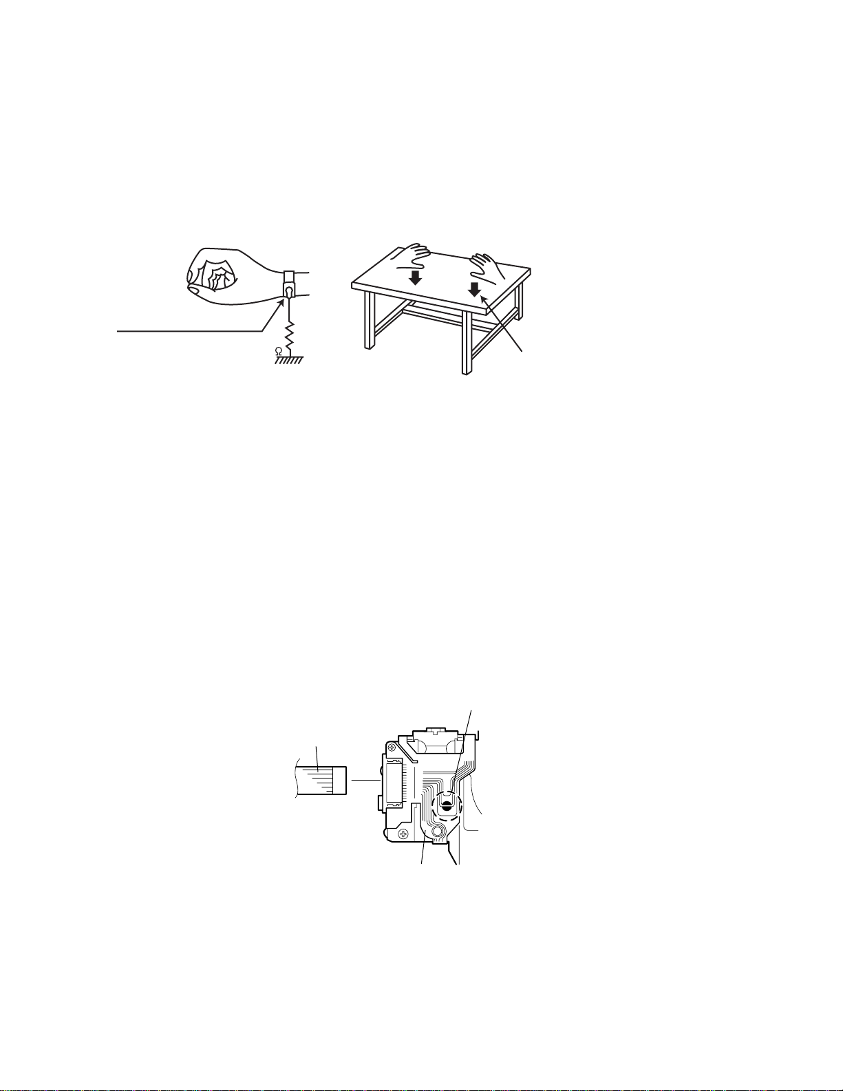
1.2.1 Grounding to prevent damage by static electricity
Static electricity in the work area can destroy the optical pickup (laser dio de) in devices such as CD players.
Be careful to use proper grounding in the area where repairs are being performed.
(1) Ground the workbench
Ground the workbench by laying conductive material (such as a conductive sh eet) or an iron plate over it before placing the
traverse unit (optical pickup) on it.
(2) Ground yourself
Use an anti-static wrist strap to release any static electricity built up in your body.
(caption)
Anti-static wrist strap
1M
Conductive material
(conductive sheet) or iron plate
(3) Handling the optical pickup
• In order to maintain quality during transport and before instal lation, both sides of the laser di ode on the replacement optica l
pickup are shorted. After replacement, return the shorted parts to their original condition.
(Refer to the text.)
• Do not use a tester to check the condition of the laser diode in the optical pickup. The tester's internal power source can easily
destroy the laser diode.
1.3 Handling the traverse unit (optical pickup)
(1) Do not subject the traverse unit (optical pickup) to strong shocks, as it is a sensitive, complex unit.
(2) Cut off the shorted part of the flexible cable using nippers, etc. after replacing the optical pickup. For specific details, refer to the
replacement procedure in the text. Remove the anti-static pin when replacing the traverse unit. Be careful not to take too long a
time when attaching it to the connector.
(3) Handle the flexible cable carefully as it may break when subjected to strong force.
(4) It is not possible to adjust the semi-fixed resistor that adjusts the laser power. Do not turn it.
1.4 Attention when traverse unit is decomposed
*Please refer to "Disassembly method" in the text for the CD pickup unit.
• Apply solder to the short land before the flexible wire is disconnected from the connector on the CD pickup unit.
(If the flexible wire is disconnected without applying solder, the CD pickup may be destroyed by static electricity.)
• In the assembly, be sure to remove solder from the short land after connecting the flexible wire.
Short-circuit point
(Soldering)
Flexible wire
1-4 (No.MA028)
Pickup
Page 5

SECTION 2
SPECIFIC SERVICE INSTRUCTIONS
This service manual does not describe SPECIFIC SERVICE INSTRUCTIONS.
(No.MA028)1-5
Page 6

SECTION 3
DISASSEMBLY
3.1 Main body
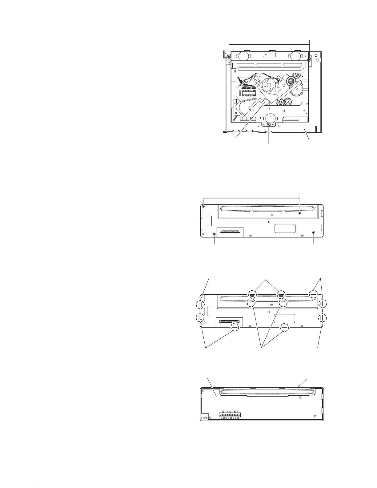
3.1.1 Removing the front panel assembly
(See Fig.1)
(1) Push the detach button in the lower right part of the front
panel assembly and remove the front panel assembly.
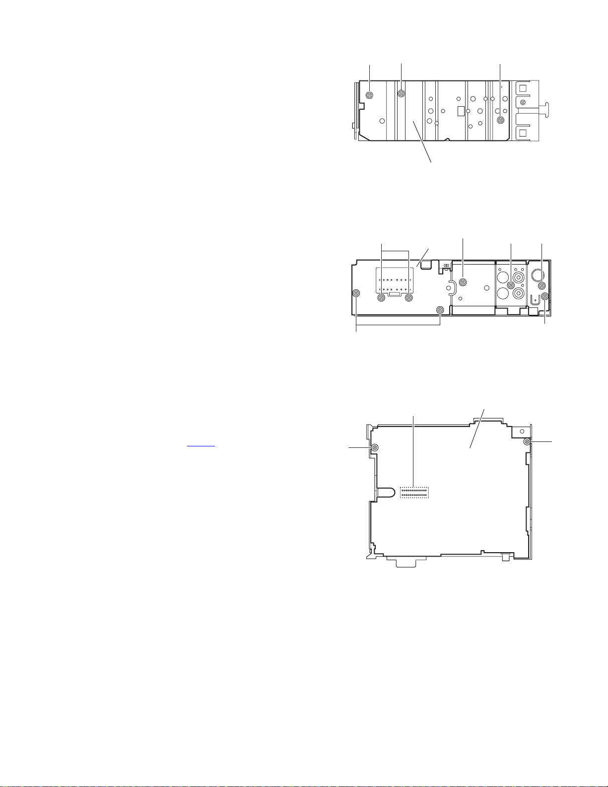
3.1.2 Removing the bottom cover
(See Fig.2)
(1) Turn the main body up side down.
(2) Insert a screwdriver under the joints to release the two
joints a on the left side, two joints b on the right side and
joint c on the back side of the main body, then remove the
bottom cover from the main body.
CAUTION:
When releasing the joints using a screwdriver, do not damage
the main board.
Front panel assembly
Joint a
Detach button
Fig.1
Bottom cover
Joint b
3.1.3 Removing the front chassis assembly
(See Fig.3)
• Prior to performing the following procedures, remove the fro nt
panel assembly and bottom cover.
(1) Remove the screw A on the left side of the main body.
(2) Release the two joints d and two joints e on the both sides
of the main body, then remove the front chassis assembly
toward the front.
Joint a
Joint c
Fig.2
Joint d Joint e
A
Joint d
Front chassis
Fig.3
Joint e
Joint b
1-6 (No.MA028)
Page 7
3.1.4 Removing the side panel
(See Fig.4)
• Prior to performing the following procedure, remove the front
panel assembly as required.
(1) Remove the screw B and two screws C attaching the heat
sink on the left side of the main body, and remove the side
panel.
3.1.5 Removing the rear bracket
(See Fig.5)
• Prior to performing the following procedure, remove the bottom
cover.
(1) Remove the three screws D, three screws E and two
screws F attaching the rear bracket on the back side of the
main body.
(2) Remove the rear bracket.
C
B
Side panel
Fig.4
EF
Rear bracket
F
C
E
3.1.6 Removing the main board
(See Fig.6)
• Prior to performing the following procedure, remove the front
panel assembly, front chassis assembly, side panel, bottom
cover and rear bracket.
(1) Remove the two screws G attaching the main board.
(2) Disconnect the connector CN501
board.
and remove the main
G
D
D
Fig.5
Main board assembly
CN501
G
Fig.6
(No.MA028)1-7
Page 8
3.1.7 Removing the CD mechanism assembly
f
(See Fig.7)
• Prior to performing the following procedure, remove the front
panel assembly, front chassis assembly, side panel, bottom
cover, rear bracket, main board and CD mechanism board.
(1) Remove the three screws H attaching the top chassis.
(2) Take out the CD mechanism assembly.
H
3.1.8 Removing the front board
(See Figs.8 to 10)
• Prior to performing the following procedure, remove the front
panel assembly.
(1) Remove the four screws J on the back side of the front pan-
el assembly. (See Fig.8)
(2) Release the eleven joints f. (See Fig.9)
(3) Take out the front board. (See Fig.10)
CD mechanism assembly
Fig.7
J
Fig.8
Joint f Joints f
Top chassis
H
J
J
Joints
1-8 (No.MA028)
Joints f
Front board
Joints f
Fig.9
Fig.10
Joint f
Front panel assembly
Page 9
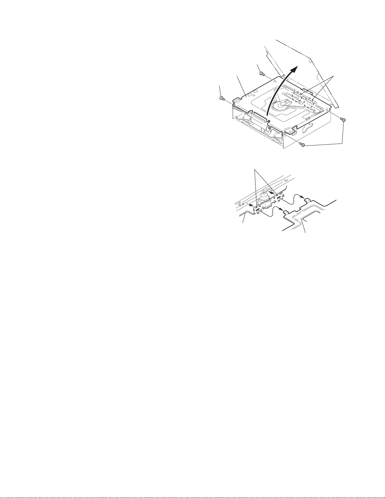
3.2 CD Mechanism Assembly
A
3.2.1 Removing the top cover
(See Figs.1 and 2)
(1) Remove the two screws A on the both side of the body.
(2) Lift the front side of the top cover and move the top cover
backward to release the two joints a.
Top cover
Joints a
A
Joints a
A
Fig.1
Fig.2
Top cover
(No.MA028)1-9
Page 10
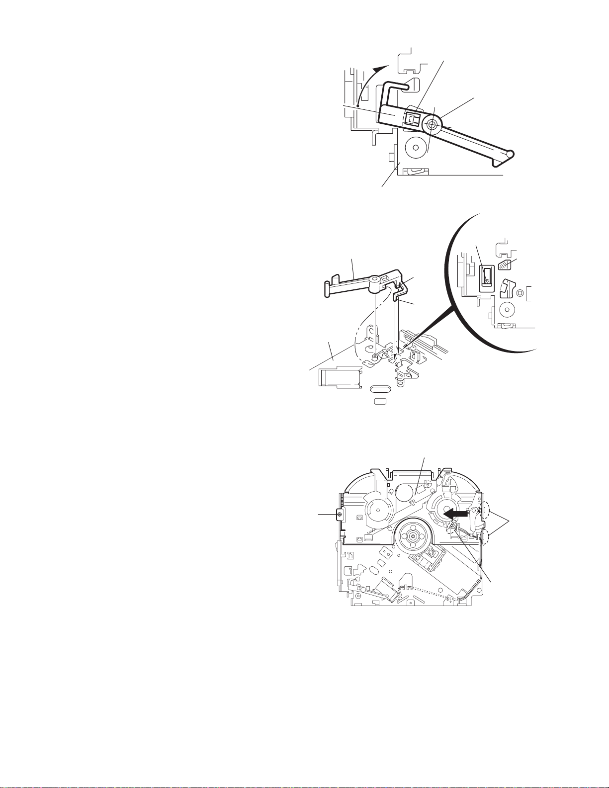
3.2.2 Removing the connector board
(See Figs.3 to 5)
CAUTION:
Before disconnecting the flexible wire from the pickup, solder
the short-circuit point on the pickup. No observance of this instruction may cause damage of the pickup.
(1) Remove the screw B fixing the connector board.
(2) Solder the short-circuit point on the connector board.
(3) Disconnect the flexible wire from the pickup.
(4) Move the connector board in the direction of the arrow to
release the two joints b.
(5) Unsolder the wire on the connector board if necessary.
CAUTION:
Unsolder the short-circuit point after reassembling.
B
Connector board
Flexible wire
Wires
Joints b
Short-circuit point
Fig.3
Short-circuit point
(Soldering)
Pickup
Flexible wire
Frame
Pickup
Fig.4
B
Connector board
Fig.5
1-10 (No.MA028)
Page 11
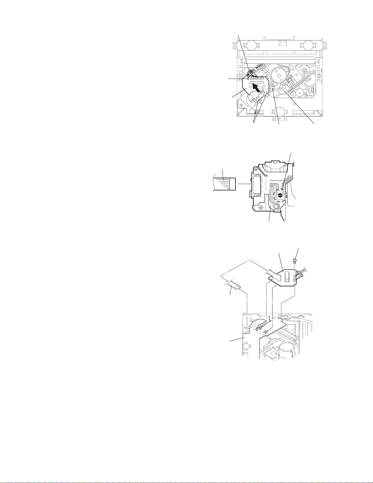
3.2.3 Removing the DET switch
(See Figs.6 and 7)
(1) Extend the two tabs c of the feed sw. holder and pull out
the switch.
(2) Unsolder the DET switch wire if necessary.
Connector
board
DET switch
DET switch
Pickup
Fig.6
Tab c
DET switch wire
Tab c
Feed sw. holder
Fig.7
(No.MA028)1-11
Page 12
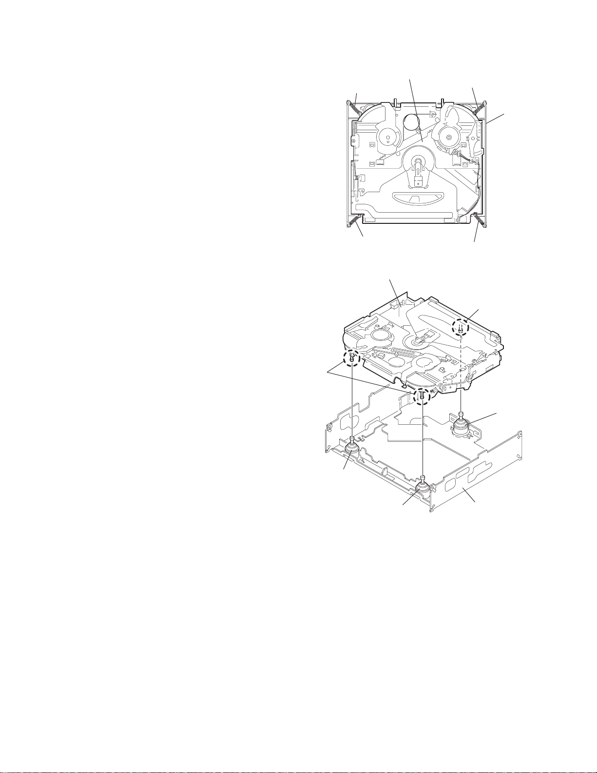
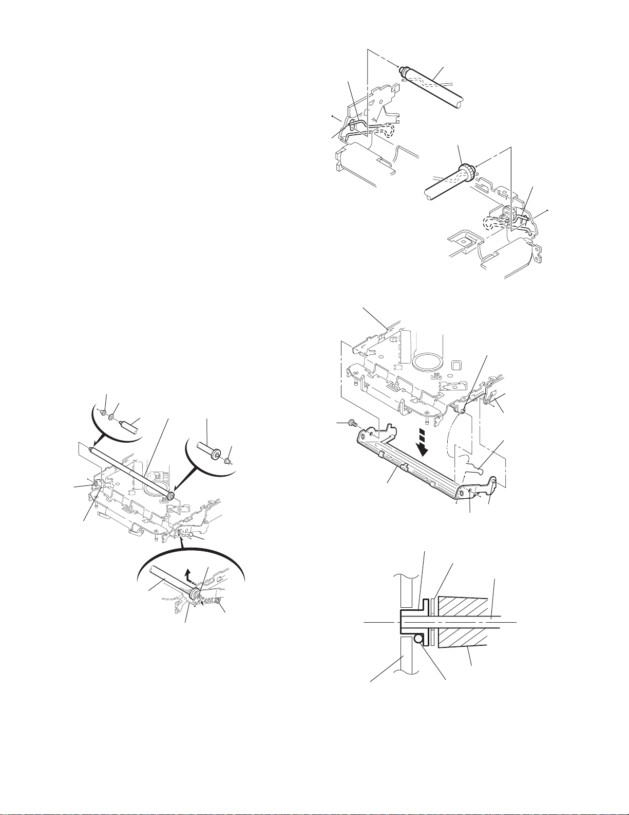
3.2.4 Removing the chassis unit
r
(See Figs.8 and 9)
• Prior to performing the following procedure, remove the top
cover and connector board.
(1) Remove the two suspension springs (L) and (R) attaching
the chassis unit to the frame.
CAUTION:
• The shape of the suspension spring (L) and (R) are different. Handle them with care.
• When reassembling, make sure that the three shafts
on the underside of the chassis unit are inserted to the
dampers certainly.
Suspension spring (R)
Chassis unit
Suspension spring (L)
Frame
Suspension spring (R)
Chassis unit
Shafts
Damper
Damper
Suspension spring (L)
Fig.8
Shaft
Dampe
Frame
Fig.9
1-12 (No.MA028)
Page 13
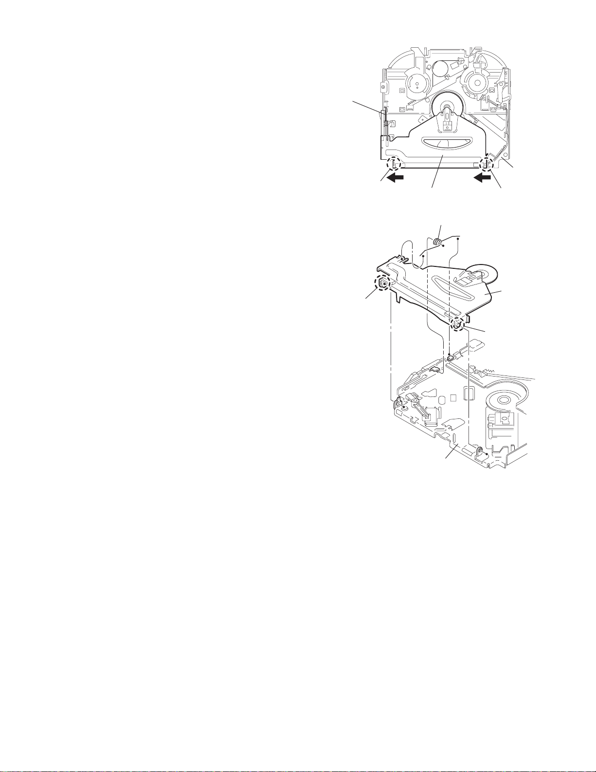
3.2.5 Removing the clamper assembly
(See Figs.10 and 11)
• Prior to performing the following procedure, re move the top
cover.
(1) Remove the clamper arm spring.
(2) Move the clamper assembly in the direction of the arrow to
release the two joints d.
Clamper arm
spring
Joint d
Joint d
Clamper assembly
Fig.10
Clamper arm spring
Chassis rivet
assembly
Joint d
Clamper
assembly
Chassis rivet assembly
Fig.11
Joint d
(No.MA028)1-13
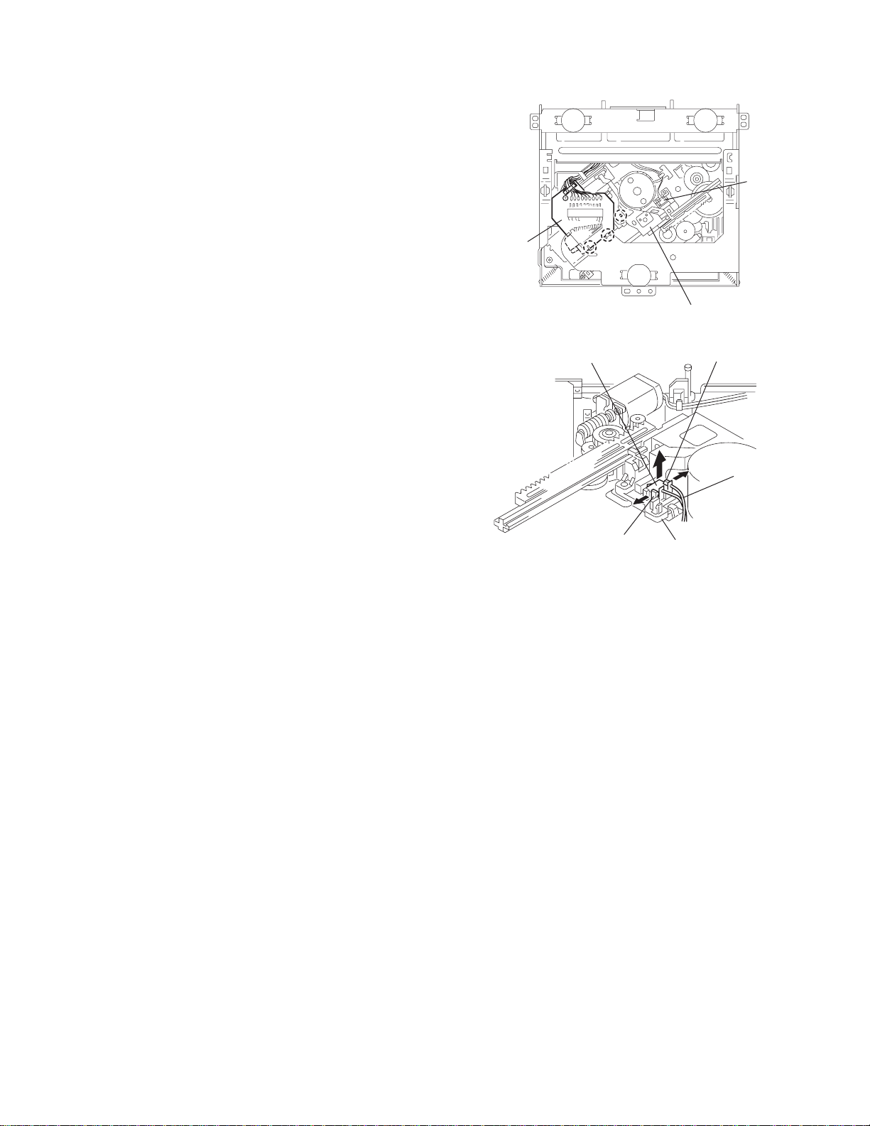
Page 14
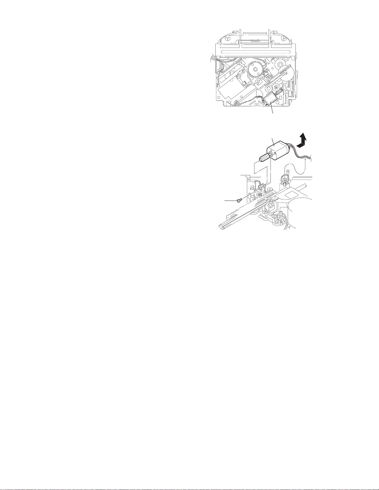
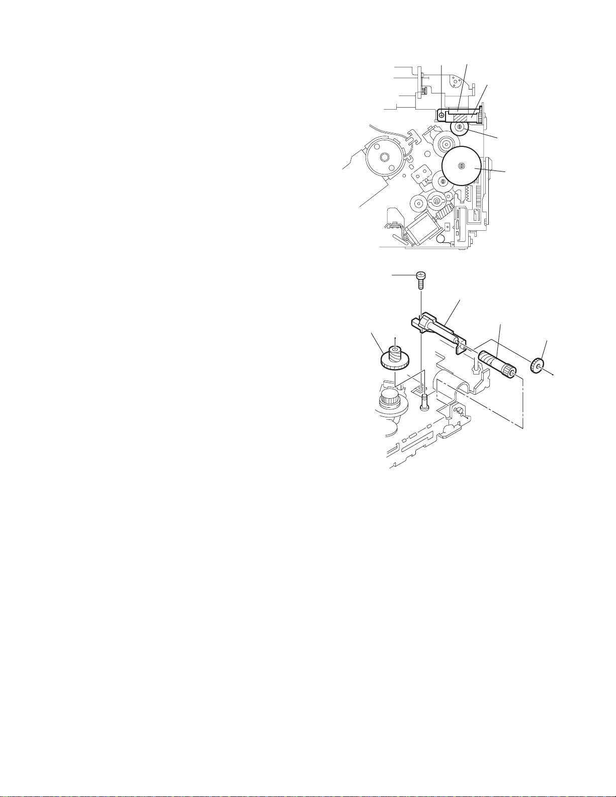
3.2.6 Removing the loading / feed motor assembly
(See Figs.12 and 13)
• Prior to performing the following procedure, remove the top
cover, connector board and chassis unit.
(1) Remove the screw C and move the loading / feed motor
assembly in the direction of the arrow to remove it from the
chassis rivet assembly.
(2) Disconnect the wire from the loading / feed motor assembly
if necessary.
CAUTION:
When reassembling, connect the wire from the loadin g /
feed motor assembly to the flame as shown in Fig.12.
Loading / feed motor assembly
Fig.12
Loading / feed motor assembly
C
Fig.13
1-14 (No.MA028)
Page 15
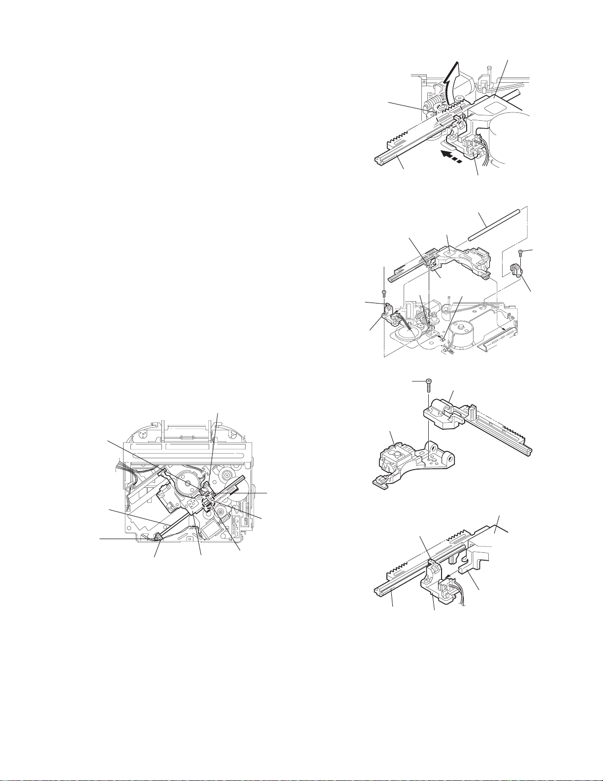
3.2.7 Removing the pickup unit
(See Figs.14 to 18)
• Prior to performing the following procedure, re move the top
cover, connector board and chassis unit.
(1) Remove the screw D and pull out the pu. shaft holder from
the pu. shaft.
(2) Remove the screw E attaching the feed sw. holder.
(3) Move the part e of the pickup unit upward with the pu. shaft
and the feed sw. holder, then release the joint f of the feed
sw. holder in the direction of the arrow. The joint g of the
pickup unit and the feed rack is released, and the feed sw.
holder comes off.
(4) Remove the pu. shaft from the pickup unit.
(5) Remove the screw F attaching the feed rack to the pickup
unit.
3.2.8 Reattaching the pickup unit
(See Figs.14 to 17)
(1) Reattach the feed rack to the pickup unit using the screw F.
(2) Reattach the feed sw. holder to the feed rack while setting
the joint g to the slot of the feed rack and setting the part f
of the feed rack to the switch of the feed sw. holder correctly.
(3) As the feed sw. holder is temporarily attached to the pickup
unit, set to the gear of the joint g and to the bending part of
the chassis (joint h) at a time.
CAUTION:
Make sure that the part i on the underside of the feed
rack is certainly inserted to the slot j of the change lock
lever.
(4) Reattach the feed sw. holder using the screw E.
(5) Reattach the pu. shaft to the p ickup uni t. Reattach the pu.
shaft holder to the pu. shaft using the screw D.
Feed sw. holder
Joint f
Joint g
Feed sw.
holder
Part e
Feed rack
Part i
E
Pickup unit
Slot j
F
Fig.15
Pu. shaft
Pickup unit
Joint f
Joint h
Fig.16
Feed rack
Pickup unit
Feed sw. holder
D
Pu. shaft
holder
Pu. shaft
D
Pu. shaft holder
Pickup unit
Fig.14
Part e
E
Joint g
Feed rack
Fig.17
Pickup unit
Joint g
Joint f
Feed sw. holder
Fig.18
(No.MA028)1-15
Page 16
3.2.9 Removing the trigger arm
r
(See Figs.19 and 20)
• Prior to performing the following procedure, remove the top
cover, connector board and clamper unit.
(1) Turn the trigger arm in the direction of the arrow to release
the joint k and pull out upward.
CAUTION:
When reassembling, insert the part m and n of the trigger
arm into the part p and q at the slot of the chassis rivet
assembly respectively and join the joint k at a time.
Chassis rivet assembly
Trigger arm
Chassis rivet
assembly
Joint k
Trigger arm
Fig.19
Part p
Part q
Part m
Part n
3.2.10 Removing the top plate assembly
(See Fig.21)
• Prior to performing the following procedure, remove the top
cover, connector board, chassis unit, and clamper assembly.
(1) Remove the screw H.
(2) Move the top plate assembly in the direction of the arrow to
release the two joints r.
(3) Unsolder the wire marked s if necessary.
H
Fig.20
Top plate assembly
Joints
s
Fig.21
1-16 (No.MA028)
Page 17
3.2.11 Removing the mode sw. / select lock arm
(See Figs.22 and 23)
• Prior to performing the following procedure, re move the top
plate assembly.
(1) Bring up the mode sw. to release from the link plate (joint t)
and turn in the direction of the arrow to release the joint u.
(2) Unsolder the wire of the mode sw. marked s if necessary.
(3) Turn the select lock arm in the direction of the arrow to re-
lease the two joints v.
(4) The select lock arm spring comes off the select lock arm at
the same time.
Top plate
Link plate
Joint u
Joint t
s
Fig.22
Select lock arm
Select lock arm
Mode sw.
Select lock arm
Top plate
Hook w
Select lock
arm spring
Link plate
Joints v
Fig.23
(No.MA028)1-17
Page 18
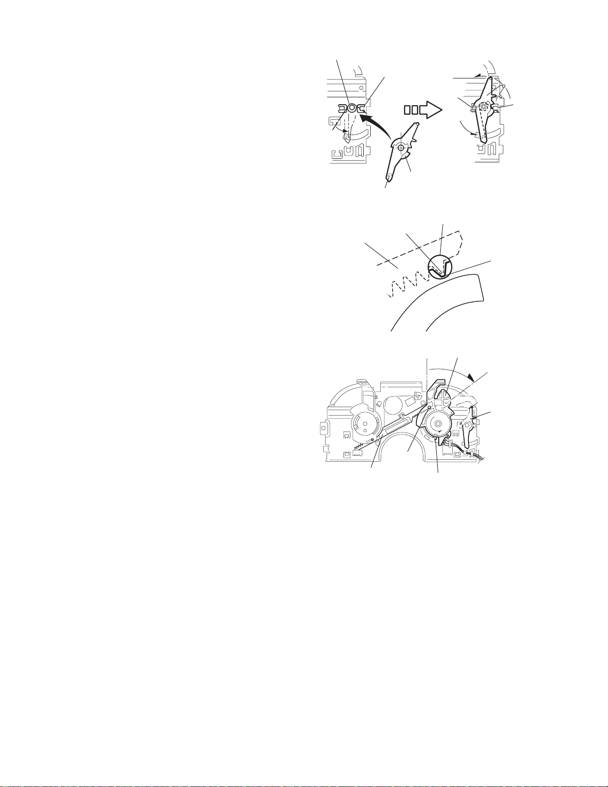
3.2.12 Reassembling the mode sw. / select lock arm
(See Figs.24 to 26)
REFERENCE:
Reverse the above removing procedure.
(1) Reattach the select lock arm spring to the top plate and set
the shorter end of the select lock arm spring to the hook w
on the top plate.
(2) Set the other longer end of the select lock arm spring to the
boss x on the underside of the select lock arm, and join the
select lock arm to the slots (joint v). Turn the select lock
arm as shown in the figure.
(3) Reattach the mode sw. whil e setting the part t to the first
peak of the link plate gear, and join the joint u.
CAUTION:
When reattaching the mode sw., check if the points y and
z are correctly fitted and if each part operates properly.
Select lock arm spring
Hook w
Joint v
Joint v
Select lock arm
Boss x
Fig.24
Joint t
Point y
Link plate
Point z
Link plate
Fig.25
Mode sw.
Select
lock arm
Joint t
Joint u
Fig.26
1-18 (No.MA028)
Page 19
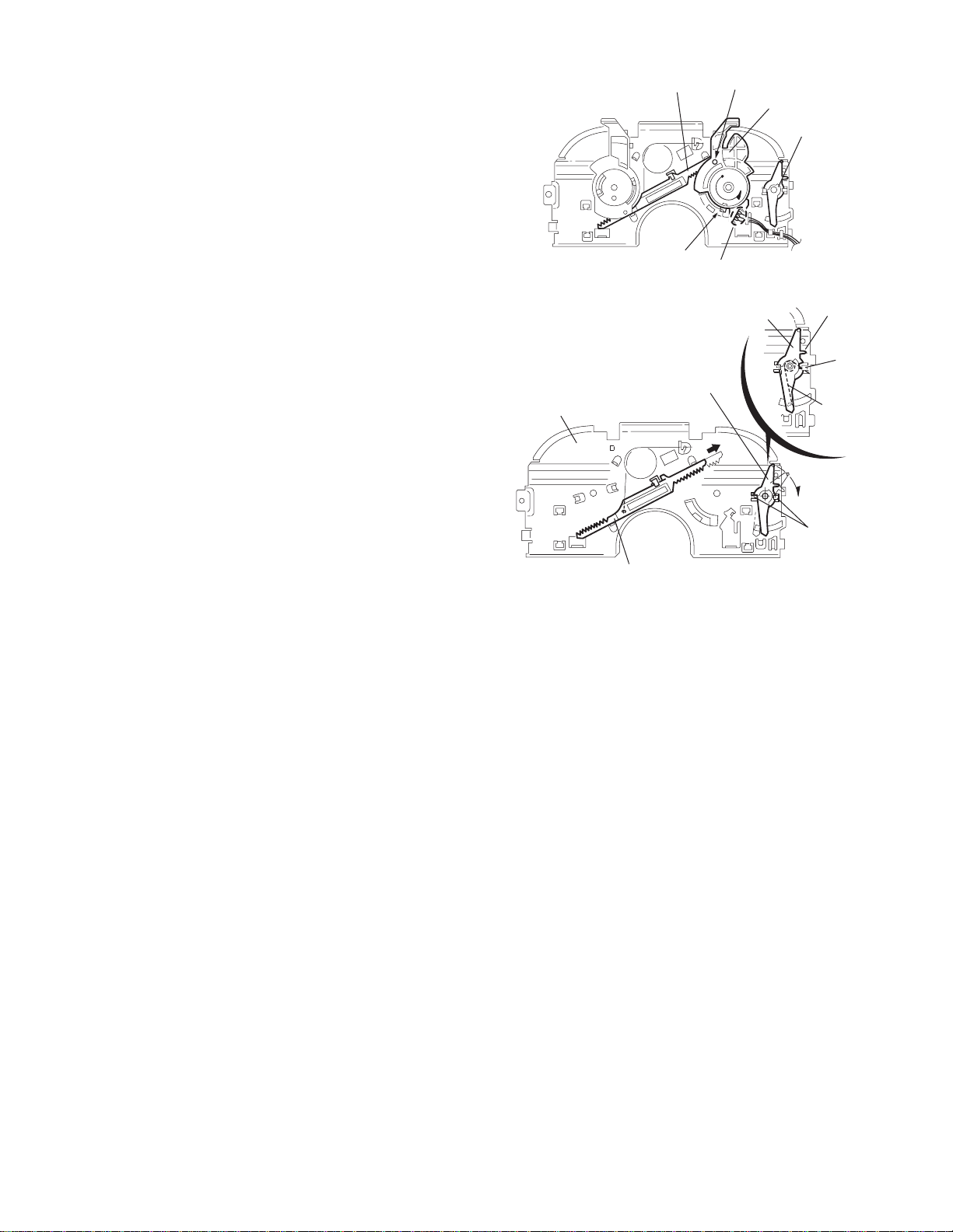
3.2.13 Removing the select arm R / link plate
(See Figs.27 and 28)
• Prior to performing the following procedure, re move the top
plate assembly.
(1) Bring up the select arm R to release from the link plate
(joint a') and turn as shown in the figure to release the two
joints b' and joint c'.
(2) Move the link plate in the direction of the arrow to release
the joint d'. Remove the link plate spring at the same time.
REFERENCE:
Before removing the link plate, remove the mode sw..
Select arm R
Joint b'
Link plate spring
Joint c'
Joint a'
Link plate
Joint b'
Fig.27
Joint r
3.2.14 Reattaching the Select arm R / link plate
(See Figs.29 and 30)
REFERENCE:
Reverse the above removing procedure.
(1) Reattach the link plate spring.
(2) Reattach the link plate to the link plate spring wh ile j oining
them at joint d'.
(3) Reattach the joint a' of the select arm R to the first peak of
the link plate while joining the two joints b' with the slots.
Then turn the select arm R as shown in the figure. The top
plate is joined to the joint c'.
CAUTION:
When reattaching the select arm R, check if the points e'
and f' are correctly fitted and if each part operates properly.
Top plate
Select arm R
Joint b'
Joint d'
Link plate
Fig.28
Link plate spring
Joint c'
Joint d'
Joint b'
Joint a'
Fig.29
Joint a'
Point e'
Link plate
Point f'
Fig.30
(No.MA028)1-19
Page 20
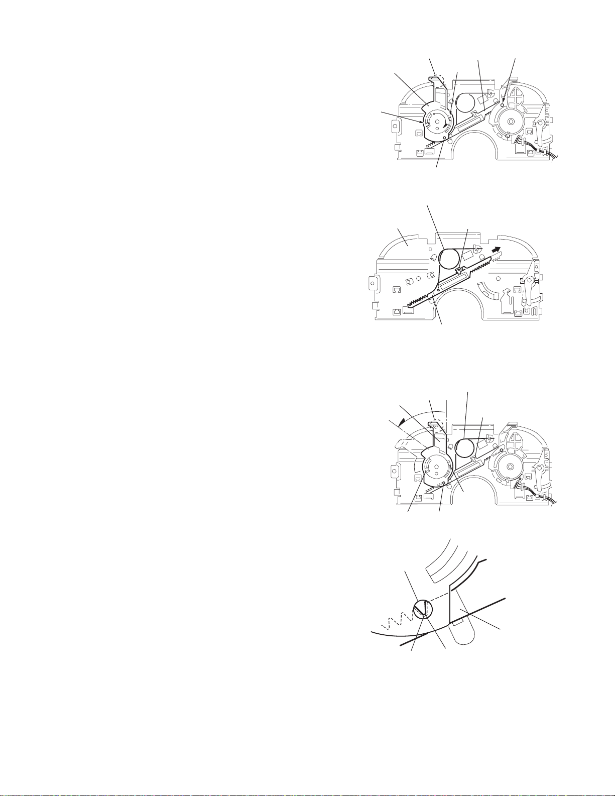
3.2.15 Removing the loading roller assembly
(See Figs.31 to 33)
• Prior to performing the following procedure, remove the
clamper assembly and top plate assembly.
(1) Push inward the loading roller a ssembly on the gear side
and detach it upward from the slot of the joint g' of the lock
arm rivet assembly.
(2) Detach the loading roller assembly from the slot of the joint
h' of the lock arm rivet assembly.
Roller guide
spring
Part k'
Loading roller assembly
Loading roller assembly
The roller guide comes off the gear section of the loading
roller assembly.
Remove the roller guide and the HL washer from the shaft
of the loading roller assembly.
(3) Remove the screw J attaching the lock arm rivet assembly.
(4) Push the shaft at the joint i' of the lock arm rivet assembly
inward to release the lock arm rivet assembly from the slot
of the L side plate.
(5) Extend the lock arm rivet assembly outward and relea se
the joint j' from the boss of the chassis rivet assembly. The
roller guide springs on both sides come off at the same
time.
CAUTION:
When reassembling, reattach the left and right roller
guide springs to the lock arm rivet assembly before reattaching the lock arm rivet assembly to the chassis rivet
assembly. Make sure to fit the part k' of the roller guide
spring inside of the roller guide. (Refer to Fig.34.)
Roller guide
HL washer
Loading roller assembly
Roller guide
Chassis rivet assembly
J
Roller guide
spring
Fig.32
Boss
L side plate
Roller guide spring
Joint h'
Roller guide spring
Loading roller assembly
Joint g'
Lock arm rivet assembly
Fig.31
Roller guide spring
Roller guide spring
Lock arm rivet assembly
Lock arm rivet assembly
Joint i'
Part j'
Fig.33
Roller guide
HL washer
Roller shaft assembly
Loading roller
Roller guide spring
Fig.34
1-20 (No.MA028)
Page 21
3.2.16 Removing the loading gear 5, 6 and 7
(See Figs.35 and 36)
• Prior to performing the following procedure, re move the top
cover, chassis unit, pickup unit and top plate assembly.
(1) Remove the screw K attaching the lo ading gear bracket.
The loading gear 6 and 7 come off the loading gear bracket.
(2) Pull out the loading gear 5.
K
Loading gear bracket
K
Loading gear 6
Loading gear 5
Loading gear 3
Fig.35
Loading gear bracket
Loading gear 5
Loading gear 6
Loading gear 7
Fig.36
(No.MA028)1-21
Page 22
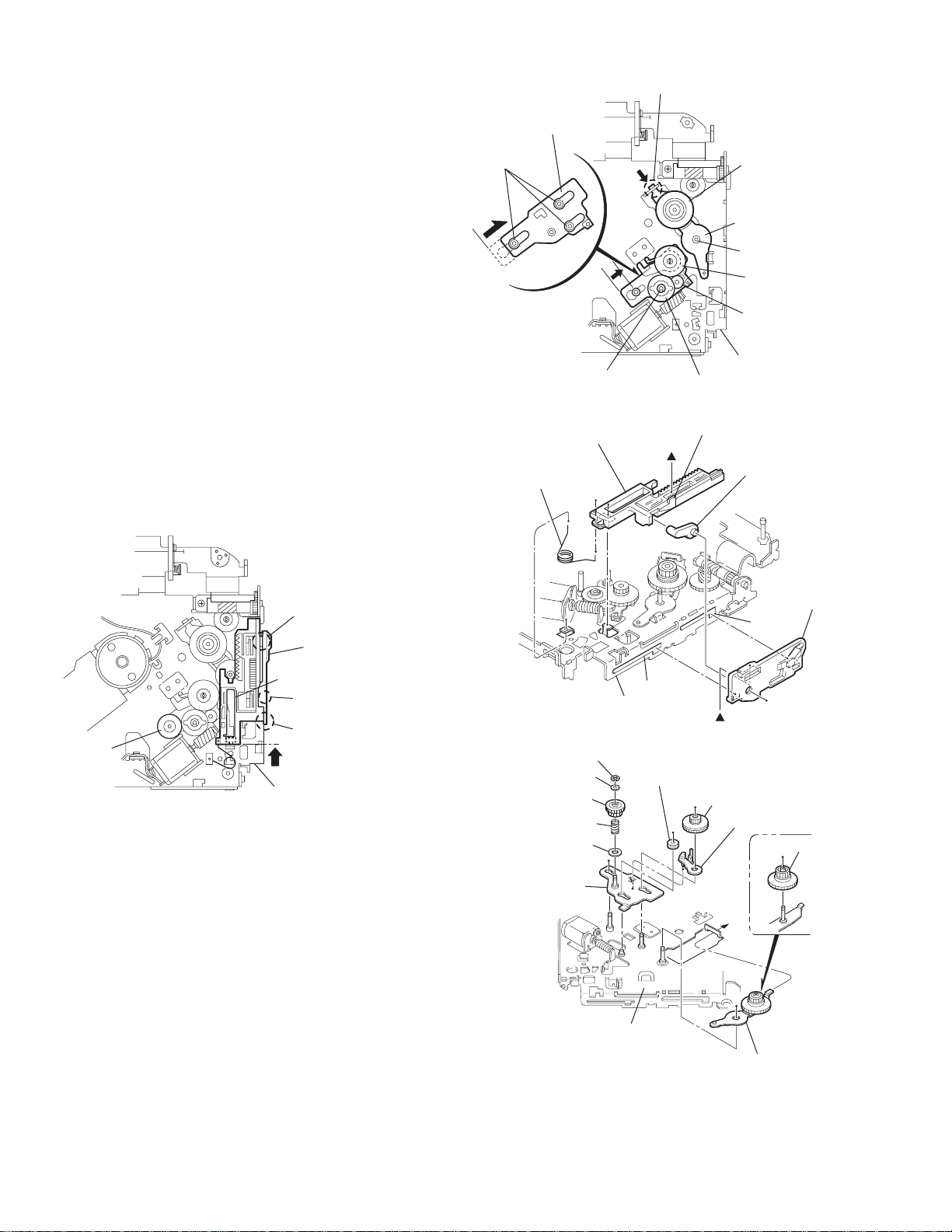
3.2.17 Removing the gears
(See Figs.37 to 40)
• Prior to performing the following procedure, remove the top
cover, chassis unit, top plate assembly and pickup unit.
• Pull out the loading gear 3. (See Fig.35.)
(1) Pull out the feed gear.
(2) Move the loading plate assembly in th e directio n of th e ar-
row to release the L side plate from the two slots m' of the
chassis rivet assembly. (See Fig.37.)
(3) Detach the loading plate assembly upward from the chas-
sis rivet assembly while releasing the joint n'. Remove the
slide hook and loading plate spring from the loading plate
assembly.
(4) Pull out the loading gear 2 and remove the change lock le-
ver.
(5) Remove the E ring and washer attaching the changer gear
2.
(6) The changer gear 2, change gear spring and adjusting
washer come off.
(7) Remove the loading gear 1.
(8) Move the change plate rivet assembly in the direction of the
arrow to release from the three shafts of the chassis rivet
assembly upward. (See Fig.38.)
(9) Detach the loading gear plate rivet assembly from the shaft
of the chassis rivet assembly upward while releasing the
joint p'. (See Figs.38 and 40.)
(10) Pull out the loading gear 4.
Change plate
rivet assembly
Shafts
E ring
Loading plate assembly
Loading plate spring
Joint p'
Loading gear 4
Loading gear plate
rivet assembly
Shaft
Loading gear 2
Loading gear 1
Chassis rivet assembly
Change gear 2
Fig.38
Joint n'
Slide hook
Feed gear
Fig.37
Slot m'
L side plate
Loading plate assembly
Joint n'
Slot m'
Chassis rivet assembly
Chassis rivet assembly
E ring
Washer
Change gear 2
Change gear spring
Adjusting washer
Change plate
rivet assembly
Chassis rivet assembly
L side plate
Slot m'
Slot m'
Fig.39
Loading gear 1
Loading gear 2
Change lock lever
Loading gear 4
1-22 (No.MA028)
Loading gear plate rivet assembly
Fig.40
Page 23
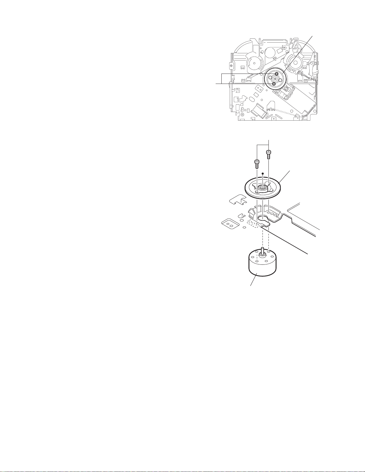
3.2.18 Removing the turn table / spindle motor
(See Figs.41 and 42)
• Prior to performing the following procedure, re move the top
cover, connector board, chassis unit and clamper assembly.
(1) Remove the two screws L attaching the spindle motor as-
sembly through the slot of the turn table on top of the body.
(2) Unsolder the wire on the connector board if necessary.
Turn table
L
Fig.41
L
Turn table
Spindle motor
Fig.42
(No.MA028)1-23
Page 24

SECTION 4
ADJUSTMENT
4.1 Adjustment method
Test instruments required for adjustment
(1) Digital oscilloscope (100MHz)
(2) Electric voltmeter
(3) Digital tester
(4) Tracking offset meter
(5) Test Disc JVC :CTS-1000
(6) Extension cable for check
EXTSH002-22P × 1
Standard volume position
Balance and Bass &Treble volume : lndication"0"
Loudness : OFF
How to connect the extension cable for adjusting
Caution:
Be sure to attach the heat sink and rear bracket onto the power amplifier IC and regulator IC respectively, before supply the power.
If voltage is applied without attaching these parts, the power amplifier IC and regulator IC will be destroyed by heat.
Standard measuring conditions
Power supply voltage DC14.4V(10.5 to 16V)
Load impedance 20KΩ(2 Speakers connection)
Output Level Line out 2.0V (Vol. MAX)
Dummy load
Exclusive dummy load should be used for AM,and FM. For FM
dummy load,there is a loss of 6dB between SSG output and
antenna input.The loss of 6dB need not be considered since
direct reading of figures are applied in this working standard.
The cardboard is cut in a suitable size.
uses for the insulation stand of mechanism.
Heat sink
Extension cable
EXTSH002-22P
Rear bracket
1-24 (No.MA028)
Page 25

5.1 Feed section
SECTION 5
TROUBLESHOOTING
Is the voltage output at
IC561 pin 22 5v or 0V
YES
Is 4V present at both
sides of the feed motor?
YES
Check the feed motor.
5.2 Focus section
When the lens is
moving:
4V
Does the S-search
waveform appear at
IC541 pins 8 and 9?
YES
5.3 Spindle section
NO
Is the wiring for IC561
pin 22 correct?
NO
Is 6V or 2V present at
IC541 pins 4 and 5?
Check IC541.
Check the circuits in
NO
the vicinity of IC541
pins 15 and 16.
Check the pickup and
its connections.
NO
NO
YES
YES
Is 5V present at IC541
pin 14?
Check the vicinity of
IC561.
YES
Check the feed motor
connection wiring.
YES
NO
Check CD 8V.
Is the disk rotated?
YES
Does the RF signal
appear at TP RF?
YES
Is the RF waveform
at TP RF distorted?
YES
Proceed to the Tracking
section
5.4 Tracking section
When the disc is rotated
at first:
Approx. 1.2V
Is the tracking error
signal output at TP TE?
NO
Is 4V present between
IC541 pins 6 and 7?
Check the spindle motor
and its wiring.
NO
Check the circuits in
the vicinity of IC501
or the pickup.
NO
NO
Check the circuits in
the vicinity of IC501
pins 25 and 26.
YES
NO
Is 4V present at IC561
pins 24 and 25?
Check the vicinity of
IC541
NO
Check the pickup and
its connections.
NO
Check IC561.
YES
YES
Check IC561.
(No.MA028)1-25
Page 26

5.5 Signal processing section
Is the sound output from
both channels (L, R)?
YES
Normal
No sound from either
channel.
YES
Is 9V present at IC301 pin
31?
YES
NONO
Compare the L-ch and
R-ch to locate the
defctive point.
NO
Check the viciniyt of the
Q321 audio power
supply.
Is the audio signal
(including sampling output
components) output to
IC151 pins 1 and 7 during
playback?
YES
Is the audio signal output
at IC301 pins 3 and 30
during playback?
YES
Check the muting circuit.
NO
NO
Check IC151 and its
peripheral circuits.
Check IC301 and its
peripheral circuits.
1-26 (No.MA028)
Page 27

5.6 Maintenance of laser pickup
(1) Cleaning the pick up lens
Before you replace the pick up, please try to clean the lens
with a alcohol soaked cotton swab.
(2) Life of the laser diode
When the life of the laser diode has expired, the following
symptoms will appear.
• The level of RF output (EFM output: amplitude of eye
pattern) will be low.
5.7 Replacement of laser pickup
Turn off the power switch and,disconnect the
power cord from the ac outlet.
Replace the pickup with a normal one.(Refer
to "Pickup Removal" on the previous page)
Is RF output
1.0 0.35Vp-p?
NO
Replace it.
YES
O.K
(3) Semi-fixed resistor on the APC PC board
The semi-fixed resistor on the APC printed circuit board
which is attached to the pickup is used to adjust the laser
power.Since this adjustment should be performed to match
the characteristics of the whole optical block, do not touch
the semi-fixed resistor.
If the laser power is lower than the specified value, the laser diode is almost worn out, and the laser pickup should
be replaced. If the semi-fixed resistor is adjusted while the
pickup is functioning normally, the laser pickup may be
damaged due to excessive current.
Plug the power cord in,and turn the power on.
At this time,check that the laser emits for
about 3seconds and the objective lens moves
up and down.
Note: Do not observe the laser beam directly.
Play a disc.
Check the eye-pattern at TP1.
Finish.
(No.MA028)1-27
Page 28

5.8 16pin cord diagram
8
7
6
BL/WH
5
4
3
2
1
BK
RD
NC
WH
GN
VI
GY
B1
A1
A2
B3
A3
B4
A4
YL
NC
NC
NC
WH/BK
GN/BK
VI/BK
GY/BK
RR+
10 VI/BK
RR-
FR-
FL+
FL-
16
15
14
13
12
11
10
9
2 VI
9 GY/BK
RL+
RL-
1 GYB2 FR+
4 WH
12 WH/BK
3 GN
11 GN/BK
BK
RD
BL
Black
Red
Blue
WH White
7 RD
16 YL
5 BL/WH
8 BK
GN
Green
VI Violet
GY
YL
MEMORY
REMOTE
GND
Gray
Yellow
ACC
B4
A2
B3
A4
1-28 (No.MA028)
B1
B2
B3
B4
RR
FR
FL
RL
VI
GY
WH
GN
Rear Right
Front Right
Front Left
Rear Left
VI/BK
GY/BK
WH/BK
GN/BK
A1
A2
A3
A4
REMOTE
ACC
MEMORY
GND
B1
NC
NC
B2
BL/WH
B3
RD
B4
Remote
ACC Line
Memory Backup Battery+
Ground
NC
YL
NC
BK
A1
A2
A3
A4
Page 29

VICTOR COMPANY OF JAPAN, LIMITED
AV & MULTIMEDIA COMPANY MOBILE ENTERTAINMENT CATEGORY 10-1,1chome,Ohwatari-machi,Maebashi-city,371-8543,Japan
(No.MA028)
Printed in Japan
WPC
Page 30

SCHEMATIC DIAGRAMS
CD RECEIVER
KD-S6060
CD-ROM No.SML200311
Area suffix
E ----------- Continental Europe
Contents
Block diagram
Standard schematic diagrams
Printed circuit boards
LOUD
SEL
DISP
MO
8
7 9 10 12
11
RPT
RND
FM
CD
SSM
AM
SCMMODE
COMPACT
DIGITAL AUDIO
2-1
2-2
2-5, 6
COPYRIGHT 2003 VICTOR COMPANY OF JAPAN, LTD.
No.MA028SCH
2003/11
Page 31

Safety precaution
!
!
Burrs formed during molding may be left over on some parts of the chassis. Therefore,
pay attention to such burrs in the case of preforming repair of this system.
Please use enough caution not to see the beam directly or touch it in case of an
adjustment or operation check.
Page 32

Block diagram
T
POSITION SET
SWITCH
LOAD&FEED
MOTOR
SPINDLE
MOTOR
SW1, SW2
PICK UP
PSW
FEED+
FEED-
SPINDLE+
SPINDLE-
SW1, SW2
VF1,VF2
VT1,VT2
LD,MD
TRACKING+
TRACKINGFOCUS+
FOCUS-
CN501
S601 to S620
KEY MATRIX
KEY0
KEY1
KEY2
SW1,SW2,PSW
SPINDLE+
SPINDLEFEED+
FEEDTRACKING+
TRACKINGFOCUS+
FOCUS-
VF1,VF2,
VT1,VT2,
MD,LD
CJ601
LM
IC541
BTL
DRIVER
KEY0
KEY1
KEY2
LCDCE
CN801
LCDSO
LCDCL
TRD,FOD
TRV,TVD
ECM,ECS
KICK
LDON,ARF
BDO,OFTR
RFDET,RFENV
VDET,TRCRS
FBAL,TBAL
TE,FE
IC501
RF AMP
IC561
DSP & DAC
OUTL
OUTR
CD.RESET,STATUS
SUBQ,SQCK,TLOCK
FLOCK,CD.SENSE
MLD,MDATA,MCLK
BLKCK
IC151
CD L.P.F.
CJ701
ANT
TU701
FM/AM
TUNER
SD/ST
MONO
SM,IFC
FM/AM
EO
FMOSC
IC701
CPU
L-CH
R-CH
IC301
E.VOLUME
SDA
SCL
OUTLF
OUTLR
OUTRF
OUTRR
CD.L
CD.R
IC901
REGULATOR
EACH BLOCK
REAR L
REAR R
BATTERY
IC321
POWER
AMP.
FRONT LEFT (+)
FRONT LEFT (-)
FRONT RIGHT(+)
FRONT RIGHT (-)
REAR LEFT (+)
REAR LEFT (-)
REAR RIGHT(+)
REAR RIGHT (-)
CN901
SPK
CJ321
LINE OU
LCD1
COM1
COM2
COM3
S1 to S48
IC601
LCD
DRIVER
LCDCL
LCDSO
LCDCE
2-1
Page 33

Standard schematic diagrams
Main amplifier section
CJ701
QNB0100-002
2SD601A/QR/-X
C731
2.2/50
C732
0.001
Q731
2SD601A/QR/-X
Q732
R736
R735
1.5k
R703
R701
R733
10k
1k
220/10
C733
D731
MTZJ10B-T2
L701
4.7u
1k
1k
1SS133-T2
R797
D701
Q792
2SB709A/QR/-X
470
R734
D791
D792
MA111-X
R794
EO
220p
1SS133-T2
D702
C717
R793
MA111-X
2.2k
47/10
C701
10k
UN2211-X
0.1/50
C703
Q791
2SB1197K/QR/-X
Q793
0.022
C718
R792
TU701
QAU0311-001
Q861
UN2111-X
R201
470
R101
470
R725
1/50
1/50
7.5K
MONO
7.5K
R102
R202
C101
TU.LCH
C201
TU.RCH
MICON.MUTE
8.2k
R708
22k
R798
SD/ST
R799
220/10
C720
47k
0.1/50
C712
Q701
UN2211-X
R702
10k
0.022
0.022
C714
C709
C710
R705
R704
150p
C713
100p
0.01
C711
Q702
S.METER
AGC
SW5V
0.1/50
0.01
C702
C725
C716
R791
10k
C715
15
15
1k
R796
R795
DTC144EKA-X
IFC
FM.OSC
FM/AM
D869
R862
470
D867
MA111-X
R861
D861
MA111-X
470
220/6.3
MTZJ4.7B-T2
C861
D866
C862
D868
MA111-X
0.082
MA111-X
MUTE
R333
D332
D333
R336
R436
R433
1k
2.2k
2.2k
1k
LRO
MA111-X
MA111-X
RRO
R334
Q332
2SD1781K/QR/-X
Q432
2SD1781K/QR/-X
R434
100
100
CJ321
QNN0519-001
Parts are safety assurance parts.
When replacing those parts make
sure to use the specified one.
IC321
LA4743K
PSW
SW1
SW2
LM
MSW
CD8V
CD.RESET
STATUS
SUBQ
SQCK
TLOCK
FLOCK
CD.SENSE
MLD
MDATA
MCLK
BLKCK
CD.RCH
CD.LCH
9V
VMC0334-001
CN801
0.1
C821
0.1
C822
MA8062/M/-X
0.1
C823
D821
MA8062/M/-X
MA8062/M/-X
MA8062/M/-X
D824
D823
D822
MA8062/M/-X
MA8062/M/-X
MA8062/M/-X
D827
D825
D826
DETACH
ILL_10V
R5V
REMOCON
LCD.SCK
LCD.SO
LCD.CE
KEY0
KEY1
KEY2
MA8062/M/-X
D828
DETACH
LM
CD.RESET
MCLK
MDATA
MLD
SCL
SDA
D803
D805
D802
D804
D801
1SS133-T2
1SS133-T2
1SS133-T2
1SS133-T2
1SS133-T2
R808
JES01-9B42
R813
IC801
R307
SDA
LRO
R302
2.2k
R908
C311
R301
22k
C303
0.22
C304
C305
0.033
0.22
C405
C404
0.033
0.22
C403
C402 C302
4.7k
R906
R401
D903
1SS133-T2
R907
39k
4.7k
R905
22k
R904
100K
0.0082 0.0082
R402
0.01
C910
0.22
2.2k
100/10
C909
100/10
C908
0.01
C907
22/16
C905
100/10
68k
MSW
1k
R811
3.3k
R812
3.3k
47k
R809
10k
0100
R843
R807
R814
R840
R841
R842
R815
R816
47k
47k
47k
47k
47k
47k
R845
0
47k
BLKCK
R844
FLOCK
TLOCK
SW1
SW2
PSW
LCD.CE
LCD.SCK
3.3k
3.3k
R805
R804
R822
PS2
CD.SENSE
STATUS
LCD.SO
3.3k
R803
2.2k
10K
R801
R817
SD/ST
REMOCON
R818
SQCK
4.7k
47k
FM/AM
SUBQ
MONO
MICON.MUTE
AGC
S.METER
R830
KEY2
R831
R829
R828
R827
R826
R825
R823
CD.RCH
C803
22p
X801
QAX0406-001Z
C804
33p
EO
TU.LCH
10/16
KEY1
TU.RCH
C802
0.01
C801
IFC
220/6.3
C824
220p
L801
4.7u
VDD
KEY0
C911
220/10
FM.OSC
47k
R836
D810
MA111-X
C807
R834
22k
R832
22k
4.7k
4.7k
R833
R835
22k
4.7k
47k
47k
47k
47k
47k
47k
CD.LCH
Q902
2SD601A/QR/-X
47k
R910
Q903
2SB709A/QR/-X
IC301
TEA6320T-X
C312
27k
R909
47/16
C306
0.0056
C406
C307
0.0056
R403
4.7k
R903
R303
4.7/25
C407
0.1
C906
47k
47k
4.7/25
R304
C308
R404
4.7/25
C408
9.1k
R901
47k
47k
4.7/25
22/16
C904
100/10
C309
0.01
C310
HA13164A
C903
22/16
IC901
C334
SCL
RRO
27k
1/50
C319
220p
C320
220p
C335
R308
1/50
27k
C435
R408
27k
1/50
220p220p
C420C419
C434
R407
27k
1/50
47k
2.2
R911
C915
C902
0.01
C901
2200/16
D901
1N5401-TU-15
L901
QQR1378-001
R902
C916
1k
2.2/50
C331
0.022
C330
0.022
D904
C427
C321
100/16
C432
0.1
RF+
RR+
LR+
RB160M-30-X
LF+
C914
RF-
RR-
D905
LR-
LF-
RB160M-30-X
22/16
C328
47/16
LR-
LF+
LR+
LF-
C332
0.1
C333
0.1
C433
0.1
RF+
RF-
RR+
RR-
R321
C329
4.7/25
R323
1k
0.1
C327
10/25
D902
SB10-03A3-T2
R322
47k
470
Q321
UN2211-X
QMFZ047-150-T
CN901
D321
1SS133-T2
MUTE
2-2
Page 34

CD servo section
FEED-
FEED+
PSW
SPINDLE-
SPINDLE+
SW1
SW2
TRACKING-
TRACKING+
FOCUS+
FOCUS-
LD
GND
MD
VR
VF1
VREF
VT1
GND
VT2
VCC
VF2
FEED-
GND
FEED+
VF2
GND
VCC
SW1
VT2
SW2
VT1
PSW
VF1
SPINDLE-
VR
SPINDLE+
LD
VREF
FOCUS-
MD
FOCUS+
TRACKINGTRACKING+
LA6589H-X
CN501
QGB2027M4-22S
R557
150
VR
IC541
FEED-
FEED+
SPINDLE+
SPINDLE-
FOCUS-
FOCUS+
TRACKING-
TRACKING+
LM
18k
R552
0
R553
VF2
VCC
SW1
VT2
SW2
VT1
PSW
VF1
LD
MD
VT1
VT2
VF2
VF1
IC501
AN8806SB-W
MD
VCC
C501
0.01
LD
0.022
C527
R502
R501
22
Q501
2SA2093/QR/-T
R512
R513
R516
R517
56k
56k
12k
12k
C502
22
12k
R546
R551
TRV
R554
100/10
3.3k
R545
MSW
C552
0.01
FOD
ECS
0.047
C504
R524
C557
2k
100/10
0.047
FOCUS+
C522
0.022
C523
0.022
C526
3p
R504
2k
R525
910
47k
R543
TRACKING-
FOCUS-
R511
C506
150p
C505
ECM
5.1k
R544
C558
0.047
TRACKING+
TBAL
R510
270k
C507
0.01
560
R542
6.8k
R541
FBAL
C528
150k
FE
TP TP
0.1
C508
C543
0.033
R509
15k
C521
560p
0.0018
1/50
RF
TP
R518
FE
R550
11K
8.2k
ARF
TE
R508
39k
C520
47p
100p
C509
Q541
2SA2093/QR/-T
C542
0.0033
TE
R507
8.2k
C518
R506
22k
0.027
C510
C529
C519
0.047
BT
0.0047
C511
C541
22/16
0.0012
R505
0.22
220k
GND
GND
BT
IC2
0.01
C512
BDO
TVD
R549
R596
8.2k
C540
C530
C555
0.047
FEED+
BT
BT
R503
68p
FEED-
GND
GND
C503
68p
1k
LDON
SPINDLE+
SPINDLE-
0.001
0.001
68p
C556
C524
C525
2k
51k
TRCRS
1M
R519
VDET
OFTR
C513
330p
5.6k
R548
VREF
TP
C516
GND
GND
RFDET
TRD
KICK
220k
R547
0.1
C514
C515
0.01
100/10
RFENV
L501
4.7U
C551
220/10
D551
1A3G-T1
TRV
TVD
ECM
ECS
KICK
TRD
FOD
FBAL
TBAL
FE
TE
RFENV
VDET
OFTR
TRCRS
RFDET
BDO
LDON
ARF
IC561
MN6627482WA
MLD
220
R574
TLOCK
0.47
C566
FLOCK
CD.SENSE
1k1k1k
R564
R563
0.0015
C576
4.7/25
47/6.3
C255
47/6.3
C152
R254
C155
R154
22k
22k
R562
0
0
R581
MDATA
1k
R561
R576
MCLK
220
R575
R156
22k
R256
22k
0.1
C577
0.01
C561
0.001
C579
X561
QAX0714-001Z
R153
27k
R152
12k
R252
12k
R253
27k
C253
150p
C153
PSW
SW1
SW2
LM
MSW
CD8V
CD.RESET
STATUS
C570
0.022
C574
0.01
C573
220/10
R560
100
L562
4.7U
C572
C571
0.01
100/10
R155
1.5k
150p
IC151
NJM4565M-WE
R255
1.5k
C256
100/10
SUBQ
SQCK
TLOCK
FLOCK
CD.SENSE
MLD
MDATA
MCLK
BLKCK
CD.RCH
GND
CD.LCH
SUBQ
SQCK
BLKCK
STATUS
CD.RESET
1k
1k
1k
1k
1k
0.01
R579
R568
R567
R570
R569
C562
C563
0.001
TP
ARF
R571
33k
R577
100k
R573
33k
220k
0.27
C564
R580
R251
0.01
0.1
C568
C567
C565
100/10
4.7U
L561
R151
18k
C151
0.001
C251
0.001
C252
18k
4.7/25
9V
2-3
Page 35

LCD & Key control section
LCD1
QLD0292-001
IC602
RPM6938-SV4
D644
R661
C611
0.012
MA8062/M/-X
10k
C612
4.7/6.3
R662
470
ILL-10V
R5V
REMOCON
CJ601
VMC0355-001
1.5k 1.2k 910 680
R616
R615
S618S619
R617
1.5k 680 5609101.2k
S620
S2
S3S4S5S6S7
S1
6809101.2k
S609S610S611S612S613
R614 R613
S603
560
560
S8S9S10
S602S604S605S606
S608
S12
S11
S13
S14
S15
S16
R601R602R603R604R605
680
S601
R606R607R611 R610 R609 R608
680
S607
R612
680
S615S616S617
S614
S17
KEY0
KEY1
KEY2
S22
S19
S20
S21
S18
S28
S23
S24
S25
S26
S27
S30
S31
S29
S32
S33
S34
1
D606
D603
LOUD
VOL+
D601
D602
1k
R645
VOL-
1k
R644
D604
D605
680
R643
SEL
DISP
680
R642
D607
D608
D609
390
R641
2
3
4
390
R640
S40
S39
S41
S37
S38
S42
S43
S46
S47
S48
S44
D613
1.2k
R637
SCM
1.2k
R636
D615
D616
D617
1k
R635
S45
S36
S37
S38
S39
S40
S41
S42
S43
FM
1k
R634
S44
S45
S46
S47
R657
51k
S48
S1S2S3
S4
S5S6S7
S8
S9
C602
680P
COM1
COM2
COM3
IC601
COM2
COM3
COM1
R651
10/6.3
C603
R653
R654
R655
R656
D642
D643
R658
2.2k
R652
2.2k
10k
10k
10k
10k
MA111-X
MA111-X
180k
D641
UDZS5.6B-X
C601
0.022
POWER
UP
D620
D618
DOWN
CD
D619
AM
2.2k
2.2k
820
R632
R633
R631
MA8062/M/-X
D645
680
R731
D731
680
R732
D732
LCD.CE
LCD.CLK
LCD.SO
S33
S34
S35
S32
S31
S30
S29
S28
S27
S26
S25
S24
S23
S22
S21
S20
S19
S18
S17
S10
S11
S13
S12
S14
S15
S16
LCD.CLK
LCD.SO
LCD.CE
KEY0
KEY1
KEY2
GND
S35
S36
5
D610
D611
6
D612
MODE
EJECT
D614
390
390
R638
R639
2-4
Page 36

Printed circuit boards
Main board
D792
D791
B753
B754
B755
R791
R703
R736
C732
R794
C731
R702
C715
D702
D701
C999
C702
C714
CJ701
R704
C713
R705
R792
B759
C709
C710
C712
Q731 Q732
Q791
C719
R735
C823
R733
R701
B752
R334
R333
D332
C720
L701
B757
Q701
C821
R734
C733
B758
D821
B751
C716
R725
C725
Q332
R336
C717
C824
C718
C711
C201
Q793
Q702
R793
D731
R795
C703
C101
B827
R808
R817
B366
C701
R829
R830
R796
R823
R826
B756
R832
R834
Q432
R433
R797
C822
R434
Q792
R102
R101
R201
R202
R708
B853
R436
R798
C861
C451
R827
R818
B451
B452
B454
C336
D869
D867
R807
R814
R815
D333
D822
Q861
R841
R809
D861
R836
R835
D866
C807
C801
D868
D826
D810
C404
C402
C403
R825
D827
C304
R828
C802
CN801
B453
R862
R861
C302
R840
C862
C303
R844
R843
C804
X801
B852
B851
C312
C311
R906
R833
R905
R831
C903
R812
D828
C803
R904
R401
C501
B551
R801
R567
B898
C405
C833
C910
IC801
D824
R402
D823
C310
R803
D825
C909
R302
R301
C305
R519
C406
C512
C309
C511
R813
R804
C306
R907
Q903
IC301
R842
R562
R805
R909
R908
D551
C908
B455
C509 C510
R811
C515
C514
C529
B456
R505
C518
D804
D802
D801
D805
D803
C528
R518
R255
R561
C907
C508
C519
R253
R564
B457
IC501
B560
C520
R508
R506
R507
R252
B855
IC901
D903
Q902
R509
C521
C253
C905
B458
C506
R504
R524
C513
R503
C904
C507
B552
R156
R910
C516
B553
C256
R155
R153
C152
C151
C526
C530
L901
R903
C998
L801
C252
R152
R151
C153
D904
C915
R911
R822
R525
C906
R901
C504
R254
R256
C911
C525
C155
R154
C524
D321
C502
D905
C902
D901
R510
C255
Q321
C307
C407
C527
C563
R572
C568
R251
C308
B152
C505
C503
R513
R516
R573
C565
C251
IC151
L562
R517
B554
C327
Q501
R511
B150
C408
C557
L561
C567
CN501
L501
R571
B558
C916
C558
B601
C523
C522
C566
R578
R323
R321
R322
R502
R512
C576
R501
R581
R303
Q541
R550
R580
R574
C577
B151
R307
C319
R576
C579
B352
R304
C542
R577
R575
R308
C320
C556
C543
R547
R544
R543
R542
C564
R553
B556
B557
R541
R548
B607
B606
R545
R546
X561
C329
C554
R557
C553
C571
IC541
R596
B602
B605
C914
C555
D902
R407
C540
B351
C434
IC561
C572
C334
R403
B604
B600
R902
C419
C573
R560
C435
C562
C561
C335
C321
B603
R404
C570
R554
C420
R552
R551
C574
B353
C427
R408
C328
R556
C541
C330
C996
B354
C333
C433
R563
C332
C551
R570
R569
R568
R579
D555
C901
C432
C597
C331
C552
Q555
C995
2-5
Page 37

Front board
D620
S601
S604
S602
D603
R603
S607
D605
R605
IC602
D601
S603
R601
R602
D602
R604
D604
R606
S605
LCD1
D606
S606 S608 S609
D607
R607
Forward side
D608
R608
S610
D609
R609
S611
D610
S614
D611
R612
S615
R613
D612
D731
D732
D616
R639
D614
S620
R610
D613
S616
R638
R637
R636
S618
R611
S612
D615
D617
S619
R616
R617
R615
R614
S613
S617
D618
D619
C603
D641
C601
R658
D643
D642
R657
C602
R651
CJ601
R652
D731
D732
R731
R732
R654
R655
R656
R653
Reverse side
IC601
R632
R633
R634
R635
IC602
D644
R641
R640
R661
R662
R631
R645
R644
D645
R643
R642
C612
C611
2-6
Page 38

< MEMO >
Page 39

VICTOR COMPANY OF JAPAN, LIMITED
AV & MULTIMEDIA COMPANY MOBILE ENTERTAINMENT CATEGORY 10-1,1chome,Ohwatari-machi,Maebashi-city,371-8543,Japan
(No.MA028SCH)
Printed in Japan
WPC
Page 40

PARTS LIST
[ KD-S6060 ]
* All printed circuit boards and its assemblies are not available as service parts.
Area suffix
E ----------- Continental Europe
EX --------------- Central Europe
MA028
- Contents -
Exploded view of general assembly and parts list (Block No.M1)
CD mechanism assembly and parts list (Block No.MB)
Electrical parts list (Block No.01~02)
Packing materials and accessories parts list (Block No.M3)
3- 2
3- 4
3- 6
3-10
3-1
Page 41

Exploded view of general assmbly and parts list
48
Block No.
8
45
46
8
47
8
41
42
3
7
10
43
44
Main board
16
9
12
13
9
5
4
35
40
M
37
38
34
36
39
LCD1
M
1
M
14
32
31
33
27
49
Front
board
6
20
25
21
26
23
24
22
30
29
28
18
15
7
11
17
A
1
2
32
6
3-2
B
6
19
Page 42

General assembly
Block No. [M][1][M][M]
Symbol No.
1 GE10043-210A TOP CHASSIS
2 GE40135-001A EARTH PLATE
3 GE30938-003A SIDE PANEL
4 GE30393-002A BOTTOM COVER
5 FSMA3004-203 INSULATOR
6 QYSDST2604Z SCREW 2.6mm x 4mm(x3)
7 FSKZ4005-001 SCREW (x2)
8 QYSDST2604Z SCREW 2.6mm x 4mm(x3)
9 QYSDST2606Z SCREW 2.6mm x 6mm(x2)
10 QYSDST2610Z SCREW 2.6mm x 10mm
11 GE10056-001A FRONT CHASSIS
12 GE30583-001A LOCK LEVER
13 FSKW4005-003 T ORS ION SPRING
14 FSXP3026-002 RLS KNOB
15 GE30999-002A COMP.SPRING
16 GE40140-002A BLIND
17 QYSDST2004M MINI SCREW 2mm x 4mm
18 GE10037-003A FRONT PANEL
19 GE30300-032A FINDER ASSY
20 GE20119-001A PRESET BUTTON
21 GE30304-001A POWER BUTTON
22 GE30305-001A EJECT BUTTON
23 GE20131-302A D.FUNC BUTTON
24 GE30307-001A SND.FUNC.BUTTON
25 GE20130-302A PUSH BUTTON
26 GE20118-002A +/- BUTTON
27 GE20120-001A UP/DOWN BUTTON
28 GE30306-001A DETACH BUTTON
29 FSKW3002-012 COMP.SPRING
30 GE30117-001A LIGHT LENS
31 GE10055-003A REAR COVER
32 VKZ4777-001 MINI SCREW (x4)
33 GE30302-003A LCD CASE
34 GE31101-001A LCD LENS
35 GE31102-001A LENS CASE
36 GE40213-001A LIGHTING SHEET
37 GE31074-001A NAME PLATE
38 LV41843-002A LASER CAUTION
39 QLD0292-001 LCD MODULE
40 QNZ0442-001 LCD CONNECTOR
41 QMFZ047-150-T FUSE 15A
42 GE40172-004A IC BRACKET
43 GE40124-002A REG BRACKET
44 QYSDST2606Z SCREW 2.6mm x 6mm
45 QYSDSF2606Z SCREW 2.6mm x 6mm
46 QYSDST2606Z SCREW 2.6mm x 6mm
47 QYSDSF2606Z SCREW 2.6mm x 6mm(x2)
48 GE30912-008A REAR BRACKET
49 GE30854-001A LED HOLDER
Part No. Part Name Description Local
3-3
Page 43

CD mechanism assembly and parts list
Grease
TNG-87
GP-501MK
CFD-005Z
GP-501A
31
C
22
112
24
61
26
36
29
Block No.
M
M
B
M
TN-2001-1011
111
74
72
35
116
34
33
111
25
73
85
15
A
19
B
21
62
D
75
112
114
11
38
30
A
23
13
32
2
111
37
27
101
93
76
94
122
100
84
73
95
38
74
100
a
14
75
94
96
77
123
97
81
32
a
113
99
28
115
D
111
91
90
89
111
93
71
C
B
92
82
18
20
87
125
88
3
12
121
16
17
124
83
86
111
3
98
83
4
1
3-4
Page 44

CD mechanism
Block No. [M][B][M][M]
Symbol No.
1 30320101T FRAME
2 30320102T TOP COVER
3 30320115T DANPER F
4 30320116T DANPER R
11 303205505T CHASSIS RIVET
12 303205503T CHANGE P. RVT A
13 303205301T CLAMPER ASS'Y
14 303205302T SPINDLE MOTOR A
15 30320502T CLAMPER ARM
16 30320503T CHANGE GEAR SPG
17 30320505T CHANGE GEAR 2
18 30320506T FEED GEAR
19 30320507T FEED RACK
20 30320509T CHANGE LOCK RAR
21 30320510T FEED SW HOLDER
22 30320511T PU SHAFT HOLDER
23 30320513T CLAMPER SUB SPG
24 30320514T FD SUB HOLDER
25 30320518T TOP PLATE
26 30320519T SELECT LOCK ARM
27 30320520T TRIGGER ARM
28 30320521T SLIDE HOOK
29 30320522T PU SHAFT
30 30320525T CLAMPER ARM SPG
31 30320526T SELECT L ARM SP
32 30320538T SUSPENSION SP R
33 30320529T SELECT ARM R
34 30320530T LINK PLATE
35 30320531T LINK PLATE SPG
36 30320523T CUSHION F
37 30320524T CUSHION R
38 30320539T SUSPENSION SP L
61 69011614T PICKUP OPT-725
62 64180406T DET SW ESE22
71 303210301T CONN PWB ASS'Y
72 30321002T MODE SW
73 30321003T LOAD MOTOR WIRE
74 30321005T MODE SW WIRE
75 30321009T SL WIRE
76 30321011T WIRE HOLDER
77 19501403T WIRE CLUMPER
81 303211301T ROLLER SHAFT AS
82 303211501T L GEAR PLATE RV
83 303211302T LOADING PLATE A
84 303211502T LOCK ARM RV ASS
85 303211303T L/F MOTOR ASS'Y
86 30321101T LOADING GEAR 1
87 30321102T LOADING GEAR 2
88 30321103T LOADING GEAR 3
89 30321104T LOADING GEAR 4
90 30321105T LOADING GEAR 5
91 30321106T LOADING GEAR 6
92 30321107T LOADING GEAR 7
93 30321111T ROLLER GUIDE
94 30321114T ROLLER GUIDE SP
95 30321116T DISC STOPPER AR
96 30321117T DISC ST ARM SPG
97 30321118T LD GEAR BRACKET
98 30321125T L SIDE PLATE
99 30321131T LOAD PLATE SPG
100 30321133T LDG ROLLER
101 18211223T COLLAR SCREW
111 9P0420031T SCREW
112 9P0420041T TAP.SCREW
113 9B0320041T SCREW
114 9C0117183T SCREW
115 9C0120203T SCREW
116 9C0317503T SCREW
121 9W0130170T PW 3.5X8X0.3
122 9W0513060T HL WASHER
123 9W0710070T L WASHER
124 9E0100152T E RING
125 9W0113020T PW 2.1X4X0.13
Part No. Part Name Description Local
3-5
Page 45

Electrical parts list
Main board
Block No. [0][1][0][0]
Symbol No.
IC151 NJM4565M-WE IC Dual ope amp
IC301 TEA6320T-X IC E.volume
IC321 LA4743K POWER IC Power amp.
IC501 AN8806SB-W IC RF & amp.
IC541 LA6589H-X BTL DRIVER IC BTL driver
IC561 MN6627482WA IC DSP & DAC
IC801 JES01-9B42 IC Main micon
IC901 HA13164A IC Regulator
Q321 UN2211-X TRANSISTOR
Q332 2SD1781K/QR/-X TRANSISTOR
Q432 2SD1781K/QR/-X TRANSISTOR
Q501 2SA2093/QR/-T TRANSISTOR
Q541 2SA2093/QR/-T TRANSISTOR
Q701 UN2211-X TRANSISTOR
Q702 KRC104S-X TRANSISTOR
Q731 2SD601A/QR/-X TRANSISTOR
Q732 2SD601A/QR/-X TRANSISTOR
Q791 2SB1197K/QR/-X TRANSISTOR
Q792 2SB709A/QR/-X TRANSISTOR
Q793 UN2211-X TRANSISTOR
Q861 UN2111-X TRANSISTOR
Q902 2SD601A/QR/-X TRANSISTOR
Q903 2SB709A/QR/-X TRANSISTOR
D321 1SS133-T2 DIODE
D332 MA111-X SI DIODE
D333 MA111-X SI DIODE
D551 1A3G-T1 SI DIODE
D701 1SS133-T2 DIODE
D702 1SS133-T2 DIODE
D791 MA111-X SI DIODE
D792 MA111-X SI DIODE
D804 1SS133-T2 DIODE
D810 MA111-X SI DIODE
D821 MA8062/M/-X Z DIODE
D822 MA8062/M/-X Z DIODE
D823 MA8062/M/-X Z DIODE
D824 MA8062/M/-X Z DIODE
D825 MA8062/M/-X Z DIODE
D826 MA8062/M/-X Z DIODE
D827 MA8062/M/-X Z DIODE
D828 MA8062/M/-X Z DIODE
D861 MTZJ4.7B-T2 Z DIODE
D866 MA111-X SI DIODE
D867 MA111-X SI DIODE
D868 MA111-X SI DIODE
D869 MA111-X SI DIODE
D901 1N5401-TU-15 DIODE
D903 1SS133-T2 DIODE
D904 RB160M-30-X SB DIODE
D905 RB160M-30-X SB DIODE
C101 QERF1HM-105Z E CAPACITOR 1uF 50V M
C151 NCB31HK-102X C CAPACITOR 1000pF 50V K
C152 QEKJ1EM-475Z E CAPACITOR 4.7uF 25V M
C153 NDC31HJ-151X C CAPACITOR 150pF 50V J
C155 QEKJ0JM-476Z E CAPACITOR 47uF 6.3V M
C201 QERF1HM-105Z E CAPACITOR 1uF 50V M
C251 NCB31HK-102X C CAPACITOR 1000pF 50V K
C252 QERF1EM-475Z E CAPACIT OR 4.7uF 25V M
C253 NDC31HJ-151X C CAPACITOR 150pF 50V J
C255 QERF0JM-476Z E CAPACITOR 47uF 6.3V M
C256 QERF1AM-107Z E CAPACIT OR 100uF 10V M
C302 NCB31HK-822X C CAPACITOR 8200pF 50V K
C303 NCB31CK-224X C CAPACITOR 0.22uF 16V K
C304 NCB21CK-224X C CAPACITOR 0.22uF 16V K
C305 NCB21HK-333X C CAPACITOR 0.033uF 50V K
C306 NCB31HK-562X C CAPACITOR 5600pF 50V K
C307 QERF1EM-475Z E CAPACIT OR 4.7uF 25V M
C308 QERF1EM-475Z E CAPACIT OR 4.7uF 25V M
C309 QEKJ1AM-107Z E CAPACITOR 100uF 10V M
Part No. Part Name Description Local
Symbol No.
C310 NCB31HK-103X C CAPACITOR 0.01uF 50V K
C311 QEKJ1AM-107Z E CAPACITOR 100uF 10V M
C312 QEKJ1CM-476Z E CAPACITOR 47uF 16V M
C319 NDC31HJ-221X C CAPACITOR 220pF 50V J
C320 NDC31HJ-221X C CAPACITOR 220pF 50V J
C321 QERF1CM-107Z E CAPACITOR 100uF 16V M
C327 QERF1CM-106Z E CAPACITOR 10uF 16V M
C328 QEKJ1CM-476Z E CAPACITOR 47uF 16V M
C329 QEKJ1EM-475Z E CAPACITOR 4.7uF 25V M
C330 NCB31HK-223X C CAPACITOR 0.022uF 50V K
C331 NCB31HK-223X C CAPACITOR 0.022uF 50V K
C332 NCB31EK-104X C CAPACITOR 0.1uF 25V K
C333 NCB31EK-104X C CAPACITOR 0.1uF 25V K
C334 QERF1HM-105Z E CAPACITOR 1uF 50V M
C335 QERF1HM-105Z E CAPACITOR 1uF 50V M
C402 NCB31HK-822X C CAPACITOR 8200pF 50V K
C403 NCB31CK-224X C CAPACITOR 0.22uF 16V K
C404 NCB21CK-224X C CAPACITOR 0.22uF 16V K
C405 NCB21HK-333X C CAPACITOR 0.033uF 50V K
C406 NCB31HK-562X C CAPACITOR 5600pF 50V K
C407 QERF1EM-475Z E CAPACITOR 4.7uF 25V M
C408 QERF1EM-475Z E CAPACITOR 4.7uF 25V M
C419 NDC31HJ-221X C CAPACITOR 220pF 50V J
C420 NDC31HJ-221X C CAPACITOR 220pF 50V J
C427 QEKJ1CM-226Z E CAPACITOR 22uF 16V M
C432 NCB31EK-104X C CAPACITOR 0.1uF 25V K
C433 NCB31EK-104X C CAPACITOR 0.1uF 25V K
C434 QERF1HM-105Z E CAPACITOR 1uF 50V M
C435 QERF1HM-105Z E CAPACITOR 1uF 50V M
C501 NCB31EK-103X C CAPACITOR 0.01uF 25V K
C502 QEKJ1AM-107Z E CAPACITOR 100uF 10V M
C503 NCS31HJ-680X C CAPACITOR 68pF 50V J
C504 QEKJ1AM-107Z E CAPACITOR 100uF 10V M
C505 NCB31EK-103X C CAPACITOR 0.01uF 25V K
C507 NCB31EK-104X C CAPACITOR 0.1uF 25V K
C508 QEKJ1HM-105Z E CAPACITOR 1uF 50V M
C509 NDC31HJ-101X C CAPACITOR 100pF 50V J
C510 NCB31EK-273X C CAPACITOR 0.027uF 25V K
C511 NCB31HK-472X C CAPACITOR 4700pF 50V K
C512 NCB31HK-103X C CAPACITOR 0.01uF 50V K
C513 NDC31HJ-331X C CAPACITOR 330pF 50V J
C514 NCB31EK-104X C CAPACITOR 0.1uF 25V K
C515 NCB31EK-103X C CAPACITOR 0.01uF 25V K
C516 QEKJ1AM-107Z E CAPACITOR 100uF 10V M
C518 NCB31CK-224X C CAPACITOR 0.22uF 16V K
C519 NCB31EK-473X C CAPACITOR 0.047uF 25V K
C520 NDC31HJ-470X C CAPACITOR 47pF 50V J
C521 NDC31HJ-561X C CAPACITOR 560pF 50V J
C522 NCB31HK-223X C CAPACITOR 0.022uF 50V K
C523 NCB31HK-223X C CAPACITOR 0.022uF 50V K
C526 NDC31HJ-3R0X C CAPACITOR 3pF 50V J
C527 NCB31EK-223X C CAPACITOR 0.022uF 25V K
C528 NCB31HK-182X C CAPACITOR 1800pF 50V K
C529 NCB31HK-122X C CAPACITOR 1200pF 50V K
C530 NDC31HJ-680X C CAPACITOR 68pF 50V J
C540 NCS31HJ-680X C CAPACITOR 68pF 50V J
C541 QERF1CM-226Z E CAPACITOR 22uF 16V M
C542 NCB31HK-332X C CAPACITOR 3300pF 50V K
C543 NCB31EK-333X C CAPACITOR 0.033uF 25V K
C551 QERF1AM-227Z E CAPACITOR 220uF 10V M
C552 NCB31EK-103X C CAPACITOR 0.01uF 25V K
C555 NCB31EK-473X C CAPACITOR 0.047uF 25V K
C556 NCB31EK-473X C CAPACITOR 0.047uF 25V K
C557 NCB31EK-473X C CAPACITOR 0.047uF 25V K
C558 NCB31EK-473X C CAPACITOR 0.047uF 25V K
C561 NCB31EK-103X C CAPACITOR 0.01uF 25V K
C562 NCB31EK-103X C CAPACITOR 0.01uF 25V K
C563 NCB31HK-102X C CAPACITOR 1000pF 50V K
C564 NCB21CK-274X C CAPACITOR 0.27uF 16V K
C565 NCB31EK-104X C CAPACITOR 0.1uF 25V K
C566 NCB31AK-474X C CAPACITOR 0.47uF 10V K
C567 QERF1AM-107Z E CAPACITOR 100uF 10V M
C568 NCB31EK-103X C CAPACITOR 0.01uF 25V K
C570 NCB31HK-222X C CAPACITOR 2200pF 50V K
C571 NCB31EK-103X C CAPACITOR 0.01uF 25V K
C572 QEKJ1AM-107Z E CAPACITOR 100uF 10V M
Part No. Part Name Description Local
3-6
Page 46

Symbol No.
Part No. Part Name Description Local
Symbol No.
Part No. Part Name Description Local
C573 QERF1AM-227Z E CAPACITOR 220uF 10V M
C574 NCB31EK-103X C CAPACITOR 0.01uF 25V K
C576 NCB31HK-152X C CAPACITOR 1500pF 50V K
C577 NCB31EK-104X C CAPACITOR 0.1uF 25V K
C579 NCB31HK-102X C CAPACITOR 1000pF 50V K
C701 QERF1AM-476Z E CAPACITOR 47uF 10V M
C702 QEKJ1HM-104Z E CAPACITOR 0.1uF 50V M
C703 QERF1HM-104Z E CAPACITOR 0.1uF 50V M
C709 NCB31EK-223X C CAPACITOR 0.022uF 25V K
C710 NCB31EK-223X C CAPACITOR 0.022uF 25V K
C711 NCB31EK-103X C CAPACITOR 0.01uF 25V K
C712 QEKJ1HM-104Z E CAPACITOR 0.1uF 50V M
C713 NCS31HJ-101X C CAPACITOR 100pF 50V J
C714 NCB31HK-103X C CAPACITOR 0.01uF 50V K
C715 NCS31HJ-151X C CAPACITOR 150pF 50V J
C717 NDC31HJ-221X C CAPACITOR 220pF 50V J
C718 NCB31EK-223X C CAPACITOR 0.022uF 25V K
C720 QERF1AM-227Z E CAPACITOR 220uF 10V M
C725 NCB31EK-103X C CAPACITOR 0.01uF 25V K
C731 QERF1HM-225Z E CAPACITOR 2.2uF 50V M
C732 NCB31HK-102X C CAPACITOR 1000pF 50V K
C733 QERF1AM-227Z E CAPACITOR 220uF 10V M
C801 QEKJ0JM-227Z E CAPACIT O R 220uF 6.3V M
C802 NCB31EK-103X C CAPACITOR 0.01uF 25V K
C803 NDC31HJ-220X C CAPACITOR 22pF 50V J
C804 NDC31HJ-330X C CAPACITOR 33pF 50V J
C807 QERF1CM-106Z E CAPACITOR 10uF 16V M
C821 NCB31EK-104X C CAPACITOR 0.1uF 25V K
C822 NCB31EK-104X C CAPACITOR 0.1uF 25V K
C823 NCB31EK-104X C CAPACITOR 0.1uF 25V K
C824 NCB31HK-221X C CAPACITOR 220pF 50V K
C861 QEKJ0JM-227Z E CAPACIT O R 220uF 6.3V M
C862 NCB31EK-823X C CAPACITOR 0.082uF 25V K
C901 QEZ0645-228 E CAPACITOR 2200uF
C902 NCB31HK-103X C CAPACITOR 0.01uF 50V K
C903 QEKJ1CM-226Z E CAPACITOR 22uF 16V M
C904 QERF1CM-226Z E CAPACITOR 22uF 16V M
C905 QERF1CM-226Z E CAPACITOR 22uF 16V M
C906 NCB31EK-104X C CAPACITOR 0.1uF 25V K
C907 NCB31HK-103X C CAPACITOR 0.01uF 50V K
C908 QERF1AM-107Z E CAPACITOR 100uF 10V M
C909 QERF1AM-107Z E CAPACITOR 100uF 10V M
C910 NCB31HK-103X C CAPACITOR 0.01uF 50V K
C911 QERF1AM-227Z E CAPACITOR 220uF 10V M
C914 NCB31EK-104X C CAPACITOR 0.1uF 25V K
C915 NCB11CK-225X C CAPACITOR 2.2uF 16V K
C916 QERF1HM-225Z E CAPACITOR 2.2uF 50V M
R101 NRSA63J-471X MG RESISTOR 470Ω 1/16W J
R102 NRSA63J-752X MG RESISTOR 7.5k
R151 NRSA63J-183X MG RESISTOR 18kΩ 1/16W J
R152 NRSA63J-123X MG RESISTOR 12k
R153 NRSA63J-273X MG RESISTOR 27k
R154 NRSA63J-223X MG RESISTOR 22kΩ 1/16W J
R155 NRSA63J-152X MG RESISTOR 1.5k
R156 NRS181J-223X MG RESISTOR 22k
R201 NRSA63J-471X MG RESISTOR 470Ω 1/16W J
R202 NRSA63J-752X MG RESISTOR 7.5k
R251 NRSA63J-183X MG RESISTOR 18kΩ 1/16W J
R252 NRSA63J-123X MG RESISTOR 12k
R253 NRSA63J-273X MG RESISTOR 27k
R254 NRSA63J-223X MG RESISTOR 22kΩ 1/16W J
R255 NRSA63J-152X MG RESISTOR 1.5k
R256 NRS181J-223X MG RESISTOR 22k
R301 NRSA63J-223X MG RESISTOR 22kΩ 1/16W J
R302 NRSA63J-222X MG RESISTOR 2.2k
R303 NRSA63J-473X MG RESISTOR 47k
R304 NRSA63J-473X MG RESISTOR 47k
R307 NRSA63J-273X MG RESISTOR 27k
R308 NRSA63J-273X MG RESISTOR 27kΩ 1/16W J
R321 NRSA63J-473X MG RESISTOR 47k
R322 NRSA63J-471X MG RESISTOR 470
R323 NRSA63J-102X MG RESISTOR 1kΩ 1/16W J
R333 NRSA63J-102X MG RESISTOR 1k
R334 NRSA63J-101X MG RESISTOR 100
R336 NRSA63J-222X MG RESISTOR 2.2kΩ 1/16W J
R401 NRSA63J-223X MG RESISTOR 22k
R402 NRSA63J-222X MG RESISTOR 2.2k
Ω
1/16W J
Ω
1/16W J
Ω
1/16W J
Ω
1/16W J
Ω
1/8W J
Ω
1/16W J
Ω
1/16W J
Ω
1/16W J
Ω
1/16W J
Ω
1/8W J
Ω
1/16W J
Ω
1/16W J
Ω
1/16W J
Ω
1/16W J
Ω
1/16W J
Ω
1/16W J
Ω
1/16W J
Ω
1/16W J
Ω
1/16W J
Ω
1/16W J
R403 NRSA63J-473X MG RESISTOR 47kΩ 1/16W J
R404 NRSA63J-473X MG RESISTOR 47kΩ 1/16W J
R407 NRSA63J-273X MG RESISTOR 27kΩ 1/16W J
R408 NRSA63J-273X MG RESISTOR 27kΩ 1/16W J
R433 NRSA63J-102X MG RESISTOR 1kΩ 1/16W J
R434 NRSA63J-101X MG RESISTOR 100
R436 NRSA63J-222X MG RESISTOR 2.2k
R501 NRSA02J-220X MG RESISTOR 22Ω 1/10W J
R502 NRSA02J-220X MG RESISTOR 22Ω 1/10W J
R503 NRS181J-102X MG RESISTOR 1kΩ 1/8W J
R504 NRSA63J-202X MG RESISTOR 2kΩ 1/16W J
R505 NRSA63J-224X MG RESISTOR 220kΩ 1/16W J
R506 NRSA63J-223X MG RESISTOR 22kΩ 1/16W J
R507 NRSA63J-822X MG RESISTOR 8.2kΩ 1/16W J
R508 NRSA63J-393X MG RESISTOR 39kΩ 1/16W J
R509 NRSA63J-153X MG RESISTOR 15kΩ 1/16W J
R510 NRSA63J-154X MG RESISTOR 150kΩ 1/16W J
R511 NRSA63J-274X MG RESISTOR 270kΩ 1/16W J
R512 NRSA63J-563X MG RESISTOR 56kΩ 1/16W J
R513 NRSA63J-563X MG RESISTOR 56kΩ 1/16W J
R516 NRSA63J-123X MG RESISTOR 12k
R517 NRSA63J-123X MG RESISTOR 12k
R518 NRSA63J-822X MG RESISTOR 8.2kΩ 1/16W J
R519 NRSA63J-105X MG RESISTOR 1MΩ 1/16W J
R524 NRSA63J-202X MG RESISTOR 2kΩ 1/16W J
R541 NRS181J-682X MG RESISTOR 6.8kΩ 1/8W J
R542 NRSA63J-561X MG RESISTOR 560Ω 1/16W J
R543 NRSA63J-473X MG RESISTOR 47kΩ 1/16W J
R544 NRSA63J-512X MG RESISTOR 5.1kΩ 1/16W J
R545 NRSA63J-332X MG RESISTOR 3.3kΩ 1/16W J
R546 NRSA63J-123X MG RESISTOR 12kΩ 1/16W J
R547 NRSA63J-224X MG RESISTOR 220kΩ 1/16W J
R548 NRSA63J-562X MG RESISTOR 5.6kΩ 1/16W J
R550 NRSA63J-113X MG RESISTOR 11kΩ 1/16W J
R551 NRSA63J-202X MG RESISTOR 2kΩ 1/16W J
R552 NRSA63J-183X MG RESISTOR 18kΩ 1/16W J
R553 NRS181J-0R0X MG RESISTOR 0Ω 1/8W J
R554 NRS181J-513X MG RESISTOR 51kΩ 1/8W J
R557 NRSA02J-151X MG RESISTOR 150Ω 1/10W J
R560 NRS181J-101X MG RESISTOR 680Ω 1/8W J
R561 NRSA63J-102X MG RESISTOR 1kΩ 1/16W J
R562 NRSA63J-102X MG RESISTOR 1kΩ 1/16W J
R563 NRSA63J-102X MG RESISTOR 1kΩ 1/16W J
R564 NRSA63J-102X MG RESISTOR 1kΩ 1/16W J
R567 NRSA63J-102X MG RESISTOR 1kΩ 1/16W J
R568 NRSA63J-102X MG RESISTOR 1kΩ 1/16W J
R569 NRSA63J-102X MG RESISTOR 1kΩ 1/16W J
R570 NRSA63J-102X MG RESISTOR 1kΩ 1/16W J
R571 NRS181J-333X MG RESISTOR 33kΩ 1/8W J
R573 NRSA63J-333X MG RESISTOR 33k
R574 NRSA63J-221X MG RESISTOR 220Ω 1/16W J
R575 NRSA63J-221X MG RESISTOR 220
R576 NRSA63J-0R0X MG RESISTOR 0
R577 NRSA63J-104X MG RESISTOR 100kΩ 1/16W J
R579 NRSA63J-102X MG RESISTOR 1k
R580 NRSA63J-224X MG RESISTOR 220k
R581 NRSA63J-0R0X MG RESISTOR 0Ω 1/16W J
R596 NRSA02J-822X MG RESISTOR 8.2k
R701 NRSA63J-102X MG RESISTOR 1kΩ 1/16W J
R702 NRSA63J-151X MG RESISTOR 150
R703 NRSA63J-102X MG RESISTOR 1k
R704 NRSA63J-151X MG RESISTOR 150Ω 1/16W J
R705 NRSA63J-103X MG RESISTOR 10k
R708 NRSA63J-822X MG RESISTOR 8.2k
R725 NRSA63J-820X MG RESISTOR 82Ω 1/16W J
R733 NRSA63J-103X MG RESISTOR 10k
R734 NRS181J-471X MG RESISTOR 470
R735 NRS181J-152X MG RESISTOR 1.5k
R736 NRSA63J-102X MG RESISTOR 1k
R791 NRSA63J-103X MG RESISTOR 10kΩ 1/16W J
R792 NRSA63J-102X MG RESISTOR 1k
R793 NRSA63J-103X MG RESISTOR 10k
R794 NRSA63J-222X MG RESISTOR 2.2kΩ 1/16W J
R795 NRS181J-150X MG RESISTOR 15
R796 NRS181J-150X MG RESISTOR 15
R797 NRS181J-100X MG RESISTOR 10Ω 1/8W J
R798 NRSA63J-223X MG RESISTOR 22k
R801 NRS181J-103X MG RESISTOR 10k
Ω
1/16W J
Ω
1/16W J
Ω
1/16W J
Ω
1/16W J
Ω
1/16W J
Ω
1/16W J
Ω
1/16W J
Ω
1/16W J
Ω
1/16W J
Ω
1/10W J
Ω
1/16W J
Ω
1/16W J
Ω
1/16W J
Ω
1/16W J
Ω
1/16W J
Ω
1/8W J
Ω
1/8W J
Ω
1/16W J
Ω
1/16W J
Ω
1/16W J
Ω
1/8W J
Ω
1/8W J
Ω
1/16W J
Ω
1/8W J
3-7
Page 47

Symbol No.
Part No. Part Name Description Local
Symbol No.
Part No. Part Name Description Local
R803 NRS181J-332X MG RESISTOR 3.3kΩ 1/8W J
R804 NRS181J-332X MG RESISTOR 3.3kΩ 1/8W J
R805 NRS181J-332X MG RESISTOR 3.3kΩ 1/8W J
R807 NRSA63J-473X MG RESISTOR 47kΩ 1/16W J
R808 NRS181J-102X MG RESISTOR 1kΩ 1/8W J
R809 NRS181J-103X MG RESISTOR 10k
R811 NRSA63J-332X MG RESISTOR 3.3k
R812 NRSA63J-332X MG RESISTOR 3.3kΩ 1/16W J
R813 NRSA63J-473X MG RESISTOR 47kΩ 1/16W J
R814 NRSA63J-473X MG RESISTOR 47kΩ 1/16W J
R815 NRSA63J-473X MG RESISTOR 47kΩ 1/16W J
R817 NRS181J-472X MG RESISTOR 4.7kΩ 1/8W J
R818 NRS181J-473X MG RESISTOR 47kΩ 1/8W J
R822 NRSA63J-222X MG RESISTOR 2.2kΩ 1/16W J
R823 NRSA63J-473X MG RESISTOR 47kΩ 1/16W J
R825 NRS181J-473X MG RESISTOR 47kΩ 1/8W J
R826 NRSA63J-473X MG RESISTOR 47kΩ 1/16W J
R827 NRSA63J-473X MG RESISTOR 47kΩ 1/16W J
R828 NRSA63J-473X MG RESISTOR 47kΩ 1/16W J
R829 NRS181J-473X MG RESISTOR 47kΩ 1/8W J
R830 NRS181J-223X MG RESISTOR 22k
R831 NRS181J-472X MG RESISTOR 4.7k
R832 NRS181J-223X MG RESISTOR 22kΩ 1/8W J
R833 NRS181J-472X MG RESISTOR 4.7kΩ 1/8W J
R834 NRS181J-223X MG RESISTOR 22kΩ 1/8W J
R835 NRS181J-472X MG RESISTOR 4.7kΩ 1/8W J
R836 NRSA63J-473X MG RESISTOR 47kΩ 1/16W J
R840 NRSA63J-473X MG RESISTOR 47kΩ 1/16W J
R841 NRSA63J-473X MG RESISTOR 47kΩ 1/16W J
R842 NRSA63J-473X MG RESISTOR 47kΩ 1/16W J
R843 NRSA63J-0R0X MG RESISTOR 0Ω 1/16W J
R844 NRSA63J-0R0X MG RESISTOR 0Ω 1/16W J
R861 NRS181J-471X MG RESISTOR 470Ω 1/8W J
R862 NRS181J-471X MG RESISTOR 470Ω 1/8W J
R901 NRSA63J-912X MG RESISTOR 9.1kΩ 1/16W J
R902 QRE142J-102X C RESISTOR 1kΩ 1/4W J
R903 NRSA63J-472X MG RESISTOR 4.7kΩ 1/16W J
R904 NRSA63J-104X MG RESISTOR 100kΩ 1/16W J
R905 NRSA63J-472X MG RESISTOR 4.7kΩ 1/16W J
R906 NRSA63J-472X MG RESISTOR 4.7kΩ 1/16W J
R907 NRSA63J-393X MG RESISTOR 39kΩ 1/16W J
R908 NRSA63J-683X MG RESISTOR 68kΩ 1/16W J
R909 NRSA63J-273X MG RESISTOR 27kΩ 1/16W J
R910 NRSA63J-473X MG RESISTOR 47kΩ 1/16W J
R911 NRS181J-473X MG RESISTOR 47kΩ 1/8W J
L501 QQL231K-4R7Y INDUCTOR I/M 4.7uH K
L561 QQL231K-4R7Y INDUCTOR I/M 4.7uH K
L562 QQL231K-4R7Y INDUCTOR I/M 4.7uH K
L701 QQL231K-4R7Y INDUCTOR I/M 4.7uH K
L801 QQL231K-4R7Y INDUCTOR I/M 4.7uH K
L901 QQR0703-001 CHOKE COIL
CJ321 QNN0519-001 SURROUND JACK
CJ701 QNB0100-002 CAR ANT JACK
CN501 QGB2027M4-22S CONNECTOR B-B (1-22)
CN801 VMC0334-001 CONNECTOR
CN901 QNZ0611-001 16P CONNECTOR
TU701 QAU0311-001 TUNER PACK
X561 QAX0714-001Z C RESONATOR 16.000MHz
X801 QAX0406-001Z CRYSTAL 4.500MHz
Ω
1/8W J
Ω
1/16W J
Ω
1/8W J
Ω
1/8W J
Front board
Block No. [0][2][0][0]
Symbol No.
IC601 PT6523LQ IC LCD driver
D601 LNJ308G81/1-3/X LED
D602 LNJ308G81/1-3/X LED
D603 LNJ308G81/1-3/X LED
D604 LNJ308G81/1-3/X LED
D605 LNJ308G81/1-3/X LED
Part No. Part Name Description Local
D606 LNJ308G81/1-3/X LED
D607 LNJ308G81/1-3/X LED
D608 LNJ308G81/1-3/X LED
D609 LNJ308G81/1-3/X LED
D610 LNJ308G81/1-3/X LED
D611 LNJ308G81/1-3/X LED
D612 LNJ308G81/1-3/X LED
D613 SML-310VT/JK/-X LED
D614 LNJ308G81/1-3/X LED
D615 LNJ308G81/1-3/X LED
D616 LNJ308G81/1-3/X LED
D617 LNJ308G81/1-3/X LED
D618 LNJ308G81/1-3/X LED
D619 LNJ308G81/1-3/X LED
D620 SML-310LT/MN/-X LED
D641 UDZS5.6B-X Z DIODE 1.5kΩ 1/10W J
D643 MA111-X SI DIODE
D645 MA8062/M/-X Z DIODE
D731 NSPW310BS/B2RS/ LED
D732 NSPW310BS/B2RS/ LED
C601 NCB31HK-223X C CAPACITOR 0.022uF 50V K
C602 NCS31HJ-681X C CAPACITOR 680pF 50V J
C603 NBE20JM-106X TA E CAPACITOR 10uF 6.3V M
R601 NRSA63J-681X MG RESISTOR 680Ω 1/16W J
R602 NRSA63J-561X MG RESISTOR 560Ω 1/16W J
R603 NRSA63J-681X MG RESISTOR 680Ω 1/16W J
R604 NRSA63J-911X MG RESISTOR 910Ω 1/16W J
R605 NRSA63J-122X MG RESISTOR 1.2kΩ 1/16W J
R606 NRSA63J-681X MG RESISTOR 680Ω 1/16W J
R607 NRSA63J-561X MG RESISTOR 560Ω 1/16W J
R608 NRSA63J-681X MG RESISTOR 680Ω 1/16W J
R609 NRSA63J-911X MG RESISTOR 910Ω 1/16W J
R610 NRSA63J-122X MG RESISTOR 1.2kΩ 1/16W J
R611 NRSA63J-152X MG RESISTOR 1.5kΩ 1/16W J
R612 NRSA63J-681X MG RESISTOR 680Ω 1/16W J
R613 NRSA63J-561X MG RESISTOR 560Ω 1/16W J
R614 NRSA63J-681X MG RESISTOR 680Ω 1/16W J
R615 NRSA63J-911X MG RESISTOR 910Ω 1/16W J
R616 NRSA63J-122X MG RESISTOR 1.2kΩ 1/16W J
R617 NRSA63J-152X MG RESISTOR 1.5kΩ 1/16W J
R631 NRSA02J-821X MG RESISTOR 820Ω 1/10W J
R632 NRSA02J-222X MG RESISTOR 2.2kΩ 1/10W J
R633 NRSA02J-222X MG RESISTOR 2.2kΩ 1/10W J
R634 NRSA02J-102X MG RESISTOR 1kΩ 1/10W J
R635 NRSA02J-102X MG RESISTOR 1kΩ 1/10W J
R636 NRSA02J-122X MG RESISTOR 1.2kΩ 1/10W J
R637 NRSA02J-122X MG RESISTOR 1.2kΩ 1/10W J
R638 NRSA02J-391X MG RESISTOR 390
R639 NRSA02J-391X MG RESISTOR 390Ω 1/10W J
R640 NRSA02J-391X MG RESISTOR 390
R641 NRSA02J-391X MG RESISTOR 390
R642 NRSA02J-681X MG RESISTOR 680Ω 1/10W J
R643 NRSA02J-681X MG RESISTOR 680
R644 NRSA02J-102X MG RESISTOR 1k
R645 NRSA02J-102X MG RESISTOR 1kΩ 1/10W J
R651 NRSA63J-222X MG RESISTOR 2.2k
R652 NRSA63J-222X MG RESISTOR 2.2kΩ 1/16W J
R653 NRSA63J-103X MG RESISTOR 10k
R654 NRSA63J-103X MG RESISTOR 10k
R655 NRSA63J-103X MG RESISTOR 10kΩ 1/16W J
R656 NRSA63J-103X MG RESISTOR 10k
R657 NRSA63J-513X MG RESISTOR 51k
R658 NRSA63J-184X MG RESISTOR 180kΩ 1/16W J
R731 NRS181J-391X MG RESISTOR 390
R732 NRS181J-391X MG RESISTOR 390
CJ601 VMC0335-001 PANEL CONNECTOR
S601 NSW0206-001X TACT SWITCH
S602 NSW0206-001X TACT SWITCH
S603 NSW0206-001X TACT SWITCH
S604 NSW0206-001X TACT SWITCH
S605 NSW0206-001X TACT SWITCH
S606 NSW0206-001X TACT SWITCH
S607 NSW0206-001X TACT SWITCH
S608 NSW0206-001X TACT SWITCH
S609 NSW0206-001X TACT SWITCH
Ω
1/10W J
Ω
1/10W J
Ω
1/10W J
Ω
1/10W J
Ω
1/10W J
Ω
1/16W J
Ω
1/16W J
Ω
1/16W J
Ω
1/16W J
Ω
1/16W J
Ω
1/8W J
Ω
1/8W J
3-8
Page 48

Symbol No.
S610 NSW0206-001X TACT SWITCH
S611 NSW0206-001X TACT SWITCH
S612 NSW0206-001X TACT SWITCH
S613 NSW0206-001X TACT SWITCH
S614 NSW0206-001X TACT SWITCH
S615 NSW0206-001X TACT SWITCH
S616 NSW0206-001X TACT SWITCH
S617 NSW0206-001X TACT SWITCH
S618 NSW0206-001X TACT SWITCH
S619 NSW0206-001X TACT SWITCH
S620 NSW0206-001X TACT SWITCH
Part No. Part Name Description Local
3-9
Page 49

Packing materials and accessories parts list
A14
P6
A15
P1
A2,A3,A4
A5,A6,A7
Block No.
M
3
P1
A1
M
M
P7
P7
P5
P2
KIT : A8,A9,A10
A11,A12
A16
P3
3-10
P4
A13
Page 50

Packing and accessories
Block No. [M][3][M][M]
Symbol No.
Part No. Part Name Description Local
A 1 GET0173-001A INST BOOK
A 2 GET0173-002A INST BOOK SPA ITA POL RUS
A 2 GET0173-003A INST BOOK
A 3 GET0173-005A INSTALL MANUAL
A 4 GET0173-006A INSTALL MANUAL
A 4 GET0173-007A INSTALL MANUAL
A 5 BT-54013-7 WARRANTY CARD
A 6 VND3050-002 IDENTITY CARD
A 7 VND3046-001 SERIAL TICKET
A 8 VKZ4027-202 PLUG NUT
A 9 VKH4871-001SS MOUNT BOLT
A 10 VKZ4328-001 LOCK NUT
A 11 WNS5000Z WASHER
A 12 GE40130-002A HOOK (x2)
A 13 FSJB3001-30C HARD CASE
A 14 GE20137-003A MOUNTING SLEEVE
A 15 GE20135-003A TRIM PLATE
A 16 QAM0089-001 16P CORD ASSY
KIT SRW-6060E SCREW PARTS KIT A8 to A12
P 1 FSPG4002-001 POLY BAG (x2)
P 2 QPA00801205 POLY BAG 8cm x 12cm
P 3 QPA01003003 POLY BAG 10cm x 30cm
P 4 FSYH4036-068 SHEET
P 5 QPC03004315P POLY BAG 30cm x 43cm
P 6 GE31075-003A CARTON
P 7 GE10036-001A EPS CUSHION (x2)
ENG GER FRE
DUT
SWE DAN FIN
GRE
S6060
E
S6060
EX
S6060
E
S6060
EX
3-11
Page 51

CD RECEIVER
CD-RECEIVER
RECEPTEUR CD
CD-RECEIVER
KD-S6060
COMPACT
DIGITAL AUDIO
ENGLISH
DEUTSCH
FRANÇAIS
LOUD
SEL
DISP
MO
8
7 9 10 12
11
RPT
RND
FM
CD
SSM
AM
SCMMODE
NEDERLANDS
For installation and connections, refer to the separate manual.
Für den Einbau und die Anschlüsse siehe das eigenständige Handbuch.
Pour l’installation et les raccordements, se référer au manuel séparé.
Bijzonderheden over de installatie en aansluiting van het apparaat vindt u in de
desbetreffende handleiding.
INSTRUCTIONS
BEDIENUNGSANLEITUNG
MANUEL D’INSTRUCTIONS
GEBRUIKSAANWIJZING
GET0173-001A
[E/EX]
Page 52

IMPORTANT FOR LASER PRODUCTS
1. CLASS 1 LASER PRODUCT
2. CAUTION: Do not open the top cover. There are no user serviceable parts inside the unit; leave all
servicing to qualified service personnel.
ENGLISH
3. CAUTION: Visible and invisible laser radiation when open and interlock failed or defeated. Avoid
direct exposure to beam.
4. REPRODUCTION OF LABEL: CAUTION LABEL, PLACED OUTSIDE THE UNIT.
How to reset your unit
While holding SEL (select), press (standby/on attenuator) for more than 2 seconds.
This will reset the built-in microcomputer.
(standby/on attenuator)
LOUD
SEL
DISP
MO
7 9 10 12
8
11
RPT
RND
SEL (select)
Notes:
• Your preset adjustments—such as preset channels or sound adjustments—will also be erased.
• If a CD is in the unit, it will eject when you reset the unit. Be careful not to drop the CD.
2
FM
CD
SSM
AM
SCMMODE
Page 53

Thank you for purchasing a JVC product. Please read all instructions carefully before operation,
to ensure your complete understanding and to obtain the best possible performance from the unit.
CONTENTS
How to reset your unit ............................... 2
How to use the MODE button ................... 3
LOCATION OF THE BUTTONS ............ 4
Control panel ............................................. 4
BASIC OPERATIONS ....................... 5
Turning on the power ................................ 5
Setting the clock ........................................ 6
RADIO OPERATIONS ...................... 7
Listening to the radio ................................. 7
Storing stations in memory ....................... 9
Tuning in to a preset station ...................... 10
CD OPERATIONS ........................... 11
Playing a CD ............................................. 11
Locating a track or a particular portion
on a CD .................................................. 12
Selecting CD playback modes .................. 12
Prohibiting CD ejection ............................. 13
How to use the MODE button
If you press MODE, the unit goes into functions mode and the number buttons work as different
function buttons.
MODE
SOUND ADJUSTMENTS ................... 14
Adjusting the sound .................................. 14
Turning on/off the loudness function ......... 14
Using the sound control memory (SCM) ... 15
Storing your own sound adjustments ........ 16
OTHER MAIN FUNCTIONS ................ 17
Selecting the level display—LEVEL .......... 17
Canceling Advanced SCM—SCM LINK ... 17
Detaching the control panel ...................... 18
TROUBLESHOOTING ...................... 19
MAINTENANCE ............................. 20
Handling discs ........................................... 20
SPECIFICATIONS........................... 21
ENGLISH
MO
8
To use these buttons as number buttons again after pressing MODE, wait for 5 seconds
without pressing any number button until the functions mode is cleared.
• Pressing MODE again also clears the functions mode.
910 127
MO
11
RPT
RND
Time countdown indicator
Note:
For security reasons, a numbered ID card is provided with this unit, and the same ID number is imprinted on
the unit’s chassis. Keep the card in a safe place, as it will help the authorities to identify your unit if stolen.
BEFORE USE
*
For safety....
• Do not raise the volume level too much, as this will
block outside sounds, making driving dangerous.
• Stop the car before performing any complicated
operations.
*
Temperature inside the car....
If you have parked the car for a long time in hot or
cold weather, wait until the temperature in the car
becomes normal before operating the unit.
3
Page 54

Control panel
ENGLISH
LOCATION OF THE BUTTONS
Display window
;dga
SCM
s
f
MO
h
ST RND RPT
l
/
j
k
1
q
2
LOUD
DISP
3
SEL
7 9 10 12
w
1 (standby/on attenuator) button
2 LOUD (loudness) button
3 SEL (select) button
4 Display window
5 Loading slot
6 0 (eject) button
7 CD button
8 AM button
9 FM button
p ¢/4 buttons
• Also functions as SSM buttons when pressed
together.
q +/– buttons
w DISP (display) button
e MO (monaural) button
r Number buttons
t RPT (repeat) button
y RND (random) button
u MODE button
i SCM (sound control memory) button
o (control panel release) button
4
7
69
54
MO
8
e
RND
11
RPT
tyr
ui
8
CD
AM
SCMMODE
p
FM
SSM
o
Display window
; SCM (sound control memory) indicator
a CD source indicator
s FM band indicators (FM1, FM2, FM3)
d AM band indicator
f Tuner reception indicators
MO (monaural), ST (stereo)
g RND (random) indicator
h RPT (repeat) indicator
j LOUD (loudness) indicator
k CD–in indicator
l Main display
/ Volume level indicator
Page 55

BASIC OPERATIONS
LOUD
SEL
DISP
123
Turning on the power
1
Turn on the power.
Note on One-Touch Operation:
When you select a source in step 2 below, the
power automatically comes on. You do not have
to press this button to turn on the power.
2
Select the source.
FM
CD
AM
To operate the tuner (FM or AM),
see pages 7 – 10.
To play a CD,
see pages 11 – 13.
3
Adjust the volume.
To increase the volume
MO
8
7 9 10 12
11
RPT
4
To drop the volume in a moment
Press briefly while listening to any
source. “AT T” starts flashing on the display, and
the volume level will drop in a moment.
To resume the previous volume level, press the
button briefly again.
To turn off the power
Press and hold for more than one
second.
“SEE YOU” appears, then the unit turns off.
• If you turn off the power while listening to a
CD, CD play will start from where playback has
been stopped previously, next time you turn on
the power.
CAUTION on Volume Setting:
CDs produce very little noise compared with other
sources. If the volume level is adjusted for the
tuner, for example, the speakers may be damaged
by the sudden increase in the output level.
Therefore, lower the volume before playing a CD
and adjust it as required during playback.
FM
CD
SSM
RND
AM
SCMMODE
Adjust the sound as you want.
(See pages 14 – 16.)
ENGLISH
To decrease the volume
Volume level appears.
Volume level indicator (see page 17)
5
Page 56

ENGLISH
DISP
ClockFrequency
LOUD
SEL
DISP
7 9 10 12
FM
CD
SSM
MO
8
RND
11
RPT
AM
SCMMODE
Setting the clock
1
Press and hold SEL (select) for more
than 2 seconds.
“CLOCK H,” “CLOCK M,” “SCM LINK,” or
“LEVEL” appears on the display.
SEL
2
Set the hour.
1 Select “CLOCK H” (hour) if not shown on
the display.
CLOCK H CLOCK M
LEVEL SCM LINK
2 Adjust the hour.
2 Adjust the minute.
4
Finish the setting.
SEL
To check the current clock time or change the
display mode
Press DISP (display) repeatedly.
Each time you press the
button, the display mode
changes as follows:
• During tuner operation:
• During CD operation:
ClockElapsed playing time
3
Set the minute.
1 Select “CLOCK M” (minute).
6
CLOCK H CLOCK M
LEVEL SCM LINK
• During power off:
The power turns on and the clock time is
shown for 5 seconds, then the power turns
off.
Page 57

RADIO OPERATIONS
LOUD
SEL
DISP
MO
8
7 9 10 12
Listening to the radio
You can use either automatic searching or
manual searching to tune in to a particular
station.
Searching for a station automatically:
Auto search
1
Select the band (FM1 – 3, AM).
FM
FM1 FM2 FM3
AM
AM
Lights up when receiving an FM stereo
broadcast with sufficient signal strength.
ST
FM
CD
SSM
RND
11
RPT
2
Start searching for a station.
AM
SCMMODE
To search for stations of higher
frequencies
To search for stations of lower
frequencies
When a station is received, searching stops.
To stop searching before a station is
received, press the same button you have
pressed for searching.
ENGLISH
Selected band appears.
Note:
This receiver has three FM bands (FM1, FM2,
FM3). You can use any one of them to listen to
an FM broadcast.
7
Page 58

Searching for a station manually:
Manual search
1
ENGLISH
Select the band (FM1 – 3, AM).
FM
FM1 FM2 FM3
AM
AM
Note:
This receiver has three FM bands (FM1, FM2,
FM3). You can use any one of them to listen to
an FM broadcast.
2
Press and hold ¢ or 4
until “M” (manual) starts flashing on
the display.
When an FM stereo broadcast is hard to
receive:
MODE
MO
8
When the MO indicator is lit on the display, the
sound you hear becomes monaural but the
reception will be improved.
1 Press MODE to enter the
functions mode while listening
to an FM stereo broadcast.
2 Press MO (monaural), while
still in the functions mode, so
that the MO indicator lights up
on the display.
Each time you press the
button, the MO indicator lights
up and goes off alternately.
MO (monaural) indicator
MO
3
Tune in to a station you want while
“M” (manual) is flashing.
To tune in to stations of higher
frequencies
To tune in to stations of lower
frequencies
• If you release your finger from the button,
the manual mode will automatically turns
off after 5 seconds.
• If you hold down the button, the frequency
keeps changing (in 50 kHz intervals for FM
and 9 kHz intervals for AM—MW/LW) until
you release the button.
8
Page 59

Storing stations in memory
You can use one of the following two methods to
store broadcasting stations in memory.
• Automatic preset of FM stations: SSM (Strongstation Sequential Memory)
• Manual preset of both FM and AM stations
FM station automatic preset: SSM
You can preset 6 local FM stations in each FM
band (FM1, FM2, and FM3).
1
Select the FM band (FM1 – 3) you
want to store FM stations into.
FM
Manual preset
You can preset up to 6 stations in each band
(FM1, FM2, FM3, and AM) manually.
Ex.: Storing FM station of 92.5 MHz into the
preset number 1 of the FM1 band.
1
Select the band (FM1 – 3, AM) you
want to store stations into (in this
example, FM1).
FM
FM1 FM2 FM3
AM
AM
ENGLISH
FM1 FM2 FM3
2
Press and hold both buttons for
more than 2 seconds.
SSM
“SSM” appears, then disappears
when automatic preset is over.
Local FM stations with the strongest signals are
searched and stored automatically in the band
number you have selected (FM1, FM2, or FM3).
These stations are preset in the number
buttons—No.1 (lowest frequency) to No.6
(highest frequency).
When automatic preset is over, the station stored
in number button 1 will be automatically tuned in.
2
Tune in to a station (in this example,
of 92.5 MHz).
To tune in to stations of higher
frequencies
To tune in to stations of lower
frequencies
CONTINUED ON THE NEXT PAGE
9
Page 60

3
Press and hold the number button
(in this example, 1) for more than
2 seconds.
ENGLISH
Tuning in to a preset station
You can easily tune in to a preset station.
7
Remember that you must store stations first. If
you have not stored them yet, see “Storing
stations in memory” on pages 9 and 10.
1
Select the band (FM1 – 3, AM).
FM
“P1” flashes for a few seconds.
4
Repeat the above procedure to store
other stations into other preset
numbers.
Notes:
• A previously preset station is erased when a new
station is stored in the same preset number.
• Preset stations are erased when the power supply to
the memory circuit is interrupted (for example,
during battery replacement). If this occurs, preset
the stations again.
FM1 FM2 FM3
AM
AM
2
Select the number (1 – 6) for the
preset station you want.
8
910 127
MO
11
RPT
RND
10
Page 61

CD OPERATIONS
LOUD
SEL
DISP
MO
8
7 9 10 12
Playing a CD
Insert a CD into the loading slot.
The unit turns on, draws
the CD and starts
playback automatically.
Note on One-Touch Operation:
When a CD is already in the loading slot, pressing
CD turns on the unit and starts playback
automatically.
The CD–in indicator flashes.
The CD–in indicator lights up.
FM
CD
SSM
RND
11
RPT
AM
SCMMODE
Note:
When a CD is inserted upside down, “EJECT”
appears on the display and the CD automatically
ejects.
To stop play and eject the CD
Press 0.
CD play stops and the CD automatically ejects
from the loading slot. The source changes to the
tuner (you will hear the last received station.)
• If you change the source, CD play also stops
(without ejecting the CD).
Next time you select “CD” as the source, CD
play starts from where playback has been
stopped previously.
Notes:
• If the ejected disc is not removed for about
15 seconds, the disc is automatically inserted again
into the loading slot to protect it from dust.
(CD play will not start this time.)
• You can eject the CD even when the unit is turned
off.
ENGLISH
Total playing time
of the inserted disc
Total track number
of the inserted disc
Elapsed playing time Current track
All tracks will be played repeatedly until you stop
playback.
About mistracking:
Mistracking may result from driving on extremely
rough roads. This does not damage the unit and
the CD, but will be annoying.
We recommend that you stop CD play while
driving on such rough roads.
11
Page 62

Locating a track or a
particular portion on a CD
To fast-forward or reverse the track
ENGLISH
Press and hold ¢, while
playing a CD, to fast-forward the
track.
Press and hold 4 , while
playing a CD, to reverse the track.
To go to the next or previous tracks
Press ¢ briefly, while playing
a CD, to go ahead to the beginning
of the next track.
Each time you press the button
consecutively, the beginning of the
next tracks is located and played
back.
Press 4 briefly, while playing
a CD, to go back to the beginning
of the current track.
Each time you press the button
consecutively, the beginning of the
previous tracks is located and
played back.
Selecting CD playback modes
To play back tracks at random
(Random Play)
You can play back all tracks on the CD at
random.
MODE
12
RND
When Random Play is turned on, the RND
indicator lights up on the display. A track
randomly selected starts playing.
1 Press MODE to enter the
functions mode while playing a
CD.
2 Press RND (random), while
still in the functions mode, so
that the RND indicator lights
up on the display.
Each time you press the
button, CD random play mode
turns on and off alternately.
RND indicator
RND
To go to a particular track directly
Press the number button corresponding to the
track number to start its playback.
8
910 127
MO
• To select a track number from 1 – 6:
Press 1 (7) – 6 (12) briefly.
• To select a track number from 7 – 12:
Press and hold 1 (7) – 6 (12) for more than one
second.
12
11
RPT
RND
Page 63

To play back tracks repeatedly
(Repeat Play)
You can play back the current track repeatedly.
MODE
11
RPT
When Repeat Play is turned on, the RPT
indicator lights up on the display. The current
track starts playing repeatedly.
1 Press MODE to enter the
functions mode while playing a
CD.
2 Press RPT (repeat), while still
in the functions mode, so that
the RPT indicator lights up on
the display.
Each time you press the
button, CD repeat play mode
turns on and off alternately.
RPT indicator
RPT
Track number of the
currently playing track
Prohibiting CD ejection
You can prohibit CD ejection and can lock a CD
in the loading slot.
ENGLISH
While pressing CD, press and hold 0 for
more than 2 seconds.
CD
“EJECT” flashes on the display for about
5 seconds, and the CD is locked and cannot be
ejected.
To cancel the prohibition and unlock the
CD
While pressing CD, press and hold 0 again for
more than 2 seconds.
“EJECT” appears on the display, and the CD
ejects from the loading slot.
The CD–in indicator flashes.
13
Page 64

SOUND ADJUSTMENTS
LOUD
Adjusting the sound
You can adjust the sound characteristics to your
preference.
ENGLISH
1
Select the item you want to adjust.
SEL
Indication To do: Range
BAS Adjust the bass. –06 (min.)
TRE Adjust the treble. –06 (min.)
FAD* Adjust the front R06 (Rear only)
BAL Adjust the left L06 (Left only)
VOL Adjust the volume. 00 (min.)
Each time you press the
button, the adjustable items
change as follows:
BAS
(bass)
(volume)
and rear speaker |
balance. F06 (Front only)
and right speaker |
balance. R06 (Right only)
VOL
TRE
(treble)
BAL
(balance)
|
+06 (max.)
|
+06 (max.)
|
50 (max.)
FAD
(fader)
2
Adjust the level.
To increase the level
To decrease the level
Ex.: When you adjust “TRE” (treble)
Note:
Normally, the + and – buttons work as the volume
control buttons. So you do not have to select “VOL”
to adjust the volume level.
Turning on/off the loudness
function
The human ear is less sensitive to low and high
frequencies at low volumes.
The loudness function can boost these
frequencies to produce a well-balanced sound at
low volume levels.
Each time you press LOUD,
the loudness function turns on
and off alternately.
LOUD (loudness) indicator
* If you are using a two-speaker system, set the fader
level to “00.”
14
Page 65

Using the sound control
memory (SCM)
You can select and store a preset sound
adjustment suitable for each playback source
(Advanced SCM).
Selecting and storing the sound
modes
Once you select a sound mode, it is stored in
memory. It will be recalled every time you select
the same source and will be shown on the
display.
A sound mode can be stored for each of the
following sources—FM1, FM2, FM3, AM, and
CD.
• If you do not want to store the sound mode
separately for each playback source, but want
to use the same sound mode for all the
sources, see “Canceling Advanced SCM—
SCM LINK” on page 17.
Select the sound mode you want.
SCM
Each time you press the
button, the sound mode
changes as follows:
Indication For: Preset values
SCM OFF (Flat sound) 00 00 ON
BEAT Rock or +02 00 ON
disco music
SOFT Quiet +01 –03 OFF
background
music
POP Light music +04 +01 OFF
BAS TRE LOUD
Recalling the sound modes
When “SCM LINK” is set to “LINK ON,”
select the source.
FM
CD
AM
The sound mode stored in memory for the
selected source is recalled.
Each time you change the
playback source, the SCM
indicator flashes on the
display.
SCM
ENGLISH
SCM OFF
SCM
Ex.: When you select “BEAT”
• When “SCM LINK” is set to “LINK ON,” the
selected sound mode can be stored in memory
for the current source and the effect applies
only to the current source.
• When “SCM LINK” is set to “LINK OFF,” the
selected sound mode effect applies to any
source.
BEAT
SOFT
POP
Notes:
• You can adjust each sound mode to your preference,
and store it in memory.
If you want to adjust and store your original sound
mode, see “Storing your own sound adjustments”
on page 16.
• To adjust the bass and treble reinforcement levels or
to turn on/off the loudness function temporarily, see
page 14. (Your adjustments will be canceled if
another source is selected.)
15
Page 66

Storing your own sound
adjustments
You can adjust the sound modes (BEAT, SOFT,
ENGLISH
POP) to your preference and store your own
adjustments in memory.
• There is a time limit in doing the following
procedure. If the setting is canceled before you
finish, start from step 1 again.
1
Call up the sound mode you want to
adjust.
SCM
SCM
• See page 15 for details.
3
Repeat step 2 to adjust the other
items.
4
Press and hold SCM until the sound
mode you have selected in step
flashes on the display.
SCM
SCM
5
Repeat the same procedure to store
Your adjustment made for the
selected sound mode is stored
in memory.
other sound modes.
1
Ex.: When you select “SOFT”
2
To adjust the bass or treble level.
1 Select “BAS” (bass) or “TRE” (treble).
SEL
Ex.: When you select “TRE” (treble)
2 Adjust the level.
To turn on or off the loudness
function.
LOUD
• See page 14 for details.
To reset to the factory settings, repeat the
same procedure and reassign the preset values
listed in the table on page 15.
16
Page 67

OTHER MAIN FUNCTIONS
Selecting the level display
—LEVEL
You can select the level display according to your
preference.
When shipped from the factory, “VOL 2” is
selected.
• VOL 1: Shows the volume level indicator.
• VOL 2: Alternates “VOL 1” setting and
• OFF: Erases the volume level indicator.
1
2
illumination display.
Press and hold SEL (select) for more
than 2 seconds.
“CLOCK H,” “CLOCK M,” “SCM LINK,” or
“LEVEL” appears on the display.
SEL
Select “LEVEL” if not shown on the
display.
CLOCK H CLOCK M
LEVEL SCM LINK
Canceling Advanced SCM
—SCM LINK
You can cancel the Advanced SCM (Sound
Control Memory), and unlink the sound modes
and the playback sources.
When shipped from the factory, a different sound
mode can be stored in memory for each source
so that you can change the sound modes simply
by changing the sources.
• LINK ON: Advanced SCM (different sound
• LINK OFF: Conventional SCM (one sound
1
Press and hold SEL (select) for more
than 2 seconds.
“CLOCK H,” “CLOCK M,” “SCM LINK,” or
“LEVEL” appears on the display.
2
Select “SCM LINK” if not shown on
the display.
modes for different sources.)
mode for all sources.)
SEL
CLOCK H CLOCK M
ENGLISH
3
Select the desired mode—“VOL 1,”
“VOL 2,” or “OFF.”
VOL 2VOL 1
OFF
4
Finish the setting.
SEL
LEVEL SCM LINK
3
Select “LINK OFF.”
4
Finish the setting.
SEL
To activate Advanced SCM (Sound Control
Memory), repeat the same procedure and press
+ to select “LINK ON” in step 3.
17
Page 68

Detaching the control panel
You can detach the control panel when leaving
the car.
When detaching or attaching the control panel,
ENGLISH
be careful not to damage the connectors on the
back of the control panel and on the panel
holder.
Detaching the control panel
Before detaching the control panel, be sure to
turn off the power.
1
Unlock the control panel.
2
Lift and pull the control panel out of
the unit.
Attaching the control panel
1
Insert the left side of the control
panel into the groove on the panel
holder.
2
Press the right side of the control
panel to fix it to the panel holder.
Note on cleaning the connectors:
If you frequently detach the control panel, the
connectors will deteriorate.
To minimize this possibility, periodically wipe the
connectors with a cotton swab or cloth moistened
with alcohol, being careful not to damage the
connectors.
18
3
Put the detached control panel into
the provided case.
Connectors
Page 69

TROUBLESHOOTING
What appears to be trouble is not always serious. Check the following points before calling a service
center.
Symptoms
• Sound cannot be heard
from the speakers.
• This unit does not work at
all.
General
• SSM (Strong-station
Sequential Memory)
automatic preset does not
work.
FM/AM
• Static noise while listening
to the radio.
• CD automatically ejects.
• CD-R cannot be played
back.
• Tracks on the CD-R cannot
be skipped.
• CD can be neither played
back nor ejected.
CD Playback
• CD sound is sometimes
interrupted.
•“NO DISC” appears on the
display.
Causes
The volume level is set to the
minimum level.
Connections are incorrect.
The built-in microcomputer
may have functioned
incorrectly due to noise, etc.
Signals are too weak.
The aerial is not connected
firmly.
CD is inserted upside down.
CD-R is not finalized.
CD is locked.
The CD player may have
functioned incorrectly.
You are driving on rough
roads.
CD is scratched.
Connections are incorrect.
No CD in the loading slot.
CD is inserted incorrectly.
Remedies
Adjust it to the optimum level.
Check the cords and
connections.
While holding SEL (select),
press (standby/on
attenuator) for more than
2 seconds to reset the unit. (The
clock setting and preset stations
stored in memory are erased.)
(See page 2.)
Store stations manually.
Connect the aerial firmly.
Insert the CD correctly.
• Insert a finalized CD-R.
• Finalize the CD-R with the
component which you used
for recording.
Unlock the CD. (See page 13.)
While holding
(standby/on attenuator), press
0 (eject) for more than
2 seconds. Be careful not to
drop the CD when it is ejected.
Stop playback while driving on
rough roads.
Change the CD.
Check the cords and
connections.
Insert a CD into the loading slot.
Insert the CD correctly.
ENGLISH
19
Page 70

MAINTENANCE
Handling discs
This unit has been designed to reproduce CDs
and CD-Rs (Recordable).
• This unit is not compatible with MP3 discs.
ENGLISH
How to handle discs
When removing a disc
from its case, press down
the center holder of the case and
lift the disc out, holding
it by the edges.
• Always hold the disc by the edges. Do not
touch its recording surface.
When storing a disc into its case, gently insert
the disc around the center holder (with the
printed surface facing up).
• Make sure to store discs into the cases after
use.
To keep discs clean
A dirty disc may not play correctly.
If a disc does become dirty, wipe it
with a soft cloth in a straight line
from center to edge.
To play new discs
New discs may have some rough
spots around the inner and outer
edges. If such a disc is used, this
unit may reject the disc.
To remove these rough spots, rub
the edges with a pencil or ball-point pen, etc.
Moisture condensation
Moisture may condense on the lens inside the
CD player in the following cases:
• After starting the heater in the car.
• If it becomes very humid inside the car.
Should this occur, the CD player may
malfunction. In this case, eject the disc and leave
the unit turned on for a few hours until the
moisture evaporates.
Center holder
When playing a CD-R
Before playing back CD-Rs, read their instructions
or cautions carefully.
• Use only “finalized” CD-Rs.
• Some CD-Rs may not play back on this unit
because of their disc characteristics, and for
the following reasons:
– Discs are dirty or scratched.
– Moisture condensation on the lens inside the
unit.
– The pickup lens inside the unit is dirty.
• CD-Rs are susceptible to high temperatures or
high humidity, so do not leave them inside your
car.
• Do not use following CD-Rs:
– Discs with stickers, labels, or protective seal
stuck to the surface.
– Discs on which labels can be directly printed
by an ink jet printer.
Using these discs under high temperatures or
high humidity may cause malfunctions or
damage to discs. For example,
– Stickers or labels may shrink and warp a
disc.
– Stickers or labels may peel off so discs
cannot be ejected.
– Print on discs may get sticky.
Read instructions or cautions about labels and
printable discs carefully.
• CD-RWs (Rewritable) cannot be played back
on this unit.
CAUTIONS:
• Do not insert 8 cm discs (single CDs) into the
loading slot. (Such discs cannot be ejected.)
• Do not insert any disc of unusual shape—like a
heart or flower; otherwise, it will cause a
malfunction.
• Do not expose discs to direct sunlight or any
heat source or place them in a place subject to
high temperature and humidity. Do not leave
them in a car.
• Do not use any solvent (for example,
conventional record cleaner, spray, thinner,
benzine, etc.) to clean discs.
20
Warped
disc
Sticker
Sticker
residue
Disc
Stick-on
label
Page 71

SPECIFICATIONS
AUDIO AMPLIFIER SECTION
Maximum Power Output:
Front: 45 W per channel
Rear: 45 W per channel
Continuous Power Output (RMS):
Front: 17 W per channel into 4 Ω, 40 Hz
to 20 000 Hz at no more than
0.8% total harmonic distortion.
Rear: 17 W per channel into 4 Ω, 40 Hz
to 20 000 Hz at no more than
0.8% total harmonic distortion.
Load Impedance: 4 Ω (4 Ω to 8 Ω allowance)
Tone Control Range:
Bass: ±10 dB at 100 Hz
Treble: ±10 dB at 10 kHz
Frequency Response: 40 Hz to 20 000 Hz
Signal-to-Noise Ratio: 70 dB
Line-Out Level/Impedance:
2.0 V/20 kΩ load (full scale)
Output Impedance: 1 kΩ
TUNER SECTION
Frequency Range:
FM: 87.5 MHz to 108.0 MHz
AM: (MW) 522 kHz to 1 620 kHz
(LW) 144 kHz to 279 kHz
CD PLAYER SECTION
Type: Compact disc player
Signal Detection System: Non-contact optical
pickup (semiconductor laser)
Number of channels: 2 channels (stereo)
Frequency Response: 5 Hz to 20 000 Hz
Dynamic Range: 90 dB
Signal-to-Noise Ratio: 95 dB
Wow and Flutter: Less than measurable limit
GENERAL
Power Requirement:
Operating Voltage: DC 14.4 V
(11 V to 16 V allowance)
Grounding System: Negative ground
Allowable Operating Temperature: 0°C to +40°C
Dimensions (W × H × D):
Installation Size (approx.):
182 mm × 52 mm × 150 mm
Panel Size (approx.):
188 mm × 58 mm × 11 mm
Mass (approx.):
1.3 kg (excluding accessories)
ENGLISH
[FM Tuner]
Usable Sensitivity:
11.3 dBf (1.0 µV/75 Ω)
50 dB Quieting Sensitivity:
16.3 dBf (1.8 µV/75 Ω)
Alternate Channel Selectivity (400 kHz):
65 dB
Frequency Response: 40 Hz to 15 000 Hz
Stereo Separation: 30 dB
Capture Ratio: 1.5 dB
[MW Tuner]
Sensitivity: 20 µV
Selectivity: 35 dB
[LW Tuner]
Sensitivity: 50 µV
Design and specifications are subject to change
without notice.
21
Page 72

Having TROUBLE with operation?
Please reset your unit
Refer to page of How to reset your unit
Haben Sie PROBLEME mit dem Betrieb?
Bitte setzen Sie Ihr Gerät zurück
Siehe Seite Zurücksetzen des Geräts
Vous avez des PROBLÈMES de fonctionnement?
Réinitialisez votre appareil
Référez-vous à la page intitulée Comment réinitialiser votre appareil
Hebt u PROBLEMEN met de bediening?
Stel het apparaat terug
Zie de pagina met de paragraaf Het apparaat terugstellen
EN, GE, FR, NL
© 2003 VICTOR COMPANY OF JAPAN, LIMITED
0903KKSMDTJEIN
Page 73

KD-S6060
Installation/Connection Manual
Einbau/Anschlußanleitung
Manuel d’installation/raccordement
Handleiding voor installatie/aansluiting
GET0173-005A
[E/EX]
ENGLISH
• This unit is designed to operate on 12 V DC,
NEGATIVE ground electrical systems.
INSTALLATION
(IN-DASH MOUNTING)
• The following illustration shows a typical installation.
However, you should make adjustments
corresponding to your specific car. If you have any
questions or require information regarding
installation kits, consult your JVC IN-CAR
ENTERTAINMENT dealer or a company supplying
kits.
1
Before mounting: Press (control panel
release button) to detach the control panel if
already attached.
* When shipped from the factory, the control
panel is packed in the hard case.
2
Remove the trim plate.
3
Remove the sleeve after disengaging the sleeve
locks.
1 Stand the unit.
Note: When you stand the unit, be careful
not to damage the fuse on the rear.
2 Insert the 2 handles between the unit and
the sleeve, as illustrated, to disengage the
sleeve locks.
3 Remove the sleeve.
Note: Be sure to keep the handles for future
use after installing the unit.
4
Install the sleeve into the dashboard.
* After the sleeve is correctly installed into the
dashboard, bend the appropriate tabs to hold
the sleeve firmly in place, as illustrated.
5
Fix the mounting bolt to the rear of the unit’s
body and place the rubber cushion over the end
of the bolt.
6
Do the required electrical connections.
7
Slide the unit into the sleeve until it is locked.
8
Attach the trim plate.
9
Attach the control panel.
DEUTSCH
• Dieses Gerät ist für einen Betrieb in elektrischen
Anlagen mit 12 V Gleichstrom und (–) Erdung
ausgelegt.
EINBAU
(IM ARMATURENBRETT)
• Die folgende Abbildung zeigt einen typischen
Einbau. Dennoch müssen Sie entsprechend Ihrem
jeweiligen Auto Anpassungen vornehmen. Bei
irgendwelchen Fragen oder wenn Sie
Informationen hinsichtlich des Einbausatzes
brauchen, wenden Sie sich an ihren JVC
Autoradiohändler oder ein Unternehmen das diese
Einbausätze vertreibt.
1
Vor dem Einbau: Drücken Sie (Freigabe der
Schalttafel), um die Arretierung der Schalttafel zu
lösen, sofern diese bereits angebracht ist.
* Bei der Auslieferung ab Werk ist die Schalttafel
im Etui verpackt.
2
Den Frontrahmen herausnehmen.
3
Die Halterung nach dem Entriegeln der
Halterungensperren abnehmen.
1 Das Gerät aufstellen.
Hinweis: Beim Aufstellen des Geräts darauf
achten, daß die Sicherung auf der Rückseite
nicht beschädigt wird.
2 Die 2 Griffe zwischen dem Gerät und der
Halterung wie abgebildet einstecken und die
Halterungensperren entriegeln.
3 Die Halterung entfernen.
Hinweis: Sicherstellen, daß die Griffe für
künftigen Gebrauch nach dem Einbau des
Geräts aufbewahrt werden.
4
Die Halterung im Armaturenbrett einbauen.
* Nach dem korrekten Einbau der Halterung im
Armaturenbrett, die entsprechenden Riegel
umknicken, um die Halterung an ihrem Platz zu
sichern, siehe Abbildung.
5
Die Befestigungsschraube an der Rückseite des
Gerätekörpers befestigen und das Ende der
Schraube mit einem Gummipuffer abdecken.
6
Nehmen Sie die erforderlichen elektrischen
Anschlüsse vor.
7
Das Gerät in die Halterung schieben, bis es
einrastet.
8
Befestigen Sie den Frontrahmen.
9
Die Schalttafel anbringen.
FRANÇAIS
• Cet appareil est conçu pour fonctionner sur des
sources de courant continu de 12 V à masse
NEGATIVE.
INSTALLATION (MONTAGE
DANS LE TABLEAU DE BORD)
• L’illustration suivante est un exemple d’installation
typique. Cependant, vous devez faire les
ajustements correspondant à votre voiture
particulière. Si vous avez des questions ou avez
besoin d’information sur des kits d’installation,
consulter votre revendeur d’autoradios JVC ou une
compagnie d’approvisionnement.
1
Avant le montage:
du panneau de commande) pour éventeullement
détacher le panneau de commande.
* Lorsque ce panneau de commande sort d’usine,
il est rangé dans un étui de transport.
2
Retirer la plaque d’assemblage.
3
Libérer les verrous du manchon et retirer le
manchon.
1
Poser l’appareil à la verticale.
Remarque:
verticale, faire attention de ne pas
endommager le fusible situé sur l’arrière.
2
Insérer les 2 poignées entre l’appareil et le
manchon comme indiqué pour désengagé les
verrous de manchon.
3
Retirer le manchon.
Remarque:
pour une utilisation ultérieur, après l’installation
de l’appareil.
4
Installer le manchon dans le tableau de bord.
* Après installation correcte du manchon dans le
tableau de bord, plier les bonnes pattes pour
maintenir fermement le manchon en place,
comme montré.
5
Monter le boulon de montage sur l’arrière du corps
de l’appareil puis passer l’amortisseur en
caoutchouc sur l’extrémité du boulon.
6
Réalisez les connexions électriques.
7
Faire glisser l’appareil dans le manchon jusqu’à ce
qu’il soit verrouillé.
8
Attachez la plaque d’assemblage.
9
Remonter le panneau de commande.
Appuyer sur (déblocage
Lorsque vous mettez l’appareil à la
S’assurer de garder les poignées
0903KKSMDTJEIN
EN, GE, FR, NL
NEDERLANDS
• Dit apparaat mag worden gebruikt bij elektrische
systemen die werken op 12 V gelijkstroom met negatieve
aarding.
INSTALLATIE (INBOUW IN
HET DASHBOARD)
• Op de volgende afbeelding kunt u zien hoe de installatie,
normaal gesproken, in zijn werk gaat. U moet echter bij
de installatie rekening houden met de bijzonderheden
van uw eigen auto. Neem bij vragen of voor meer
bijzonderheden over inbouwpakketten contact op met uw
JVC car audio dealer of een dealer of een bedrijf dat
inbouwpakketten levert.
1
Voordat u aan de montage van het apparaat
begint: Druk op (het bedieningspaneel
vrijgeven) als u het bedieningspaneel wilt
loskoppelen indien dit aan de eenheid is
vastgekoppeld.
* Standaard wordt het bedieningspaneel bij het
verlaten van de fabriek los verpackt meegeleverd.
2
Verwijder de sierplaat.
3
Verwijder het huis nadat u de klemmen hebt
losgemaakt.
1 Zet het apparaat rechtop.
Opmerking: Wanneer u het apparaat rechtop
zet, moet u erop letten dat u de zekering aan de
achterkant niet beschadigt.
2 Plaats de 2 hendels, zoals afgebeeld, tussen het
apparaat en het huis, om de klemmen los te
maken.
3 Verwijder het huis.
Opmerking: Bewaar de hendels nadat u het
apparaat hebt geïnstalleerd, zodat u ze ook in de
toekomst kunt gebruiken.
4
Installeer het huis in het dashboard.
* Nadat het huis op de juiste wijze in het dashboard
is geplaatst, moet u de palletjes, zoals afgebeeld,
stevig op hun plaats duwen.
5
Maak de bevestigingsbout aan de achterkant van het
apparaat vast en plaats de rubberdop over het uiteinde
van de bout.
6
Breng de vereiste elektrische verbindingen tot stand.
7
Schuif het apparaat in het huis totdat het vergrendeld
is.
8
Bevestig een sierplaat.
9
Bevestig het bedieningspaneel.
Control panel
12
Schalttafel
Panneau de commande
Bedieningspaneel
Handle
Griff
Poignée
Hendel
3
Lock Plate
Arretierplättchen
Plaque de verrouillage
Vergrendelingsplaat
Slot
Schlitz
Fente
Sleuf
Fuse
Sicherung
Fusible
Zekering
Sleeve
Halterung
Manchon
Huis
9
Control panel
Schalttafel
Panneau de commande
Bedieningspaneel
8
1
Trim plate
Frontrahmen
Plaque d’assemblage
Sierplaat
Rubber cushion
Gummipuffer
Amortisseur en caoutchouc
Rubberdop
Sleeve
Halterung
Manchon
Huis
7
Trim plate
Frontrahmen
Plaque d’assemblage
Sierplaat
4
4
Dashboard
Armaturenbrett
Tableau de bord
Dashboard
184 mm
53 mm
5
Mounting bolt
Befestigungsschraube
Boulon de montage
Bevestigingsbout
6
*
See “ELECTRICAL CONNECTIONS.”
Siehe „ELEKTRISCHE ANSCHLÜSSE“.
Référez-vous “RACCORDEMENTS
ELECTRIQUES” .
Zie “ELEKTRISCHE VERBINDINGEN”.
Page 74

• When using the optional stay
• Beim Verwenden der Anker-Option
• Lors de l’utilisation du hauban en option
• Wanneer u de steun gebruikt (facultatief)
Washer
Unterlegscheibe
Rondelle
Sluitring
Dashboard
Armaturenbrett
Tableau de bord
Dashboard
Less than 30˚
Weniger als 30˚
Moins de 30˚
Kleiner dan 30˚
Fire wall
Feuerwand
Cloison
Brandscherm
Sleeve
Halterung
Manchon
Huis
Lock nut
Sicherungsmutter
Ecrou d’arrêt
Contra-moer
Screw (option)
Schraube (Option)
Vis (en option)
Schroef (facultatief)
Mounting bolt
Befestigungsschraube
Boulon de montage
Bevestigingsbout
Install the unit at an angle of less
than 30˚.
Stellen Sie das Gerät mit einem
Winkel von weniger als 30˚ auf.
Installez l’appareil avec un angle de
moins de 30˚.
Installeer het toestel met een hoek kleiner
dan 30˚.
Stay (option)
Anker (Option)
Hauban (en option)
Steun (facultatief)
• When installing the unit without using the sleeve
• Beim Einbau des Geräts ohne Halterung
• Lors de l’installation de l’appareil scans utiliser de manchon
• Wanneer u het apparaat zonder huis installeert
In a Toyota for example, first remove the car radio and install the unit in its place.
Zum Beispiel in einem Toyota zuerst das Autoradio ausbauen und dann das Gerät an seinem Platz einbauen.
Par exemple dans une Toyota, retirer d’abord l’autoradio et installer l’appareil à la place.
Voorbeeld: Bij een Toyota moet u eerst de autoradio verwijderen en daarna het apparaat installeren.
Flat type screws (M5 x 8 mm)*
Senkkopfschrauben (M5 x 8 mm)*
Vis à tête plate (M5 x 8 mm)
Platkopschroeven (M5 x 8 mm)*
Note : When installing the unit on the mounting bracket, make sure to use the 8 mm-long screws. If longer screws are used,
Hinweis : Beim Anbringen des Gerät an der Konsole sicherstellen, daß 8 mm lange Schrauben verwendet werden. Werden
Remarque :
Opmerking : Wanneer u het apparaat aan de bevestigingsklem vastmaakt, moet u de 8 mm lange schroeven gebruiken. Als u langere schroeven
they could damage the unit.
längere Schrauben verwendet, können sie das Gerät beschädigen.
Lors de l’installation de l’appareil sur le support de montage, s’assurer d’utiliser des vis d’une longueur de 8 mm. Si
des vis plus longues sont utilisées, elles peuvent endommager l’appareil.
gebruikt, kan het apparaat worden beschadigd.
*
Pocket
Taschen
Poche
Zak
Bracket*
Konsole*
Support
Console*
*
Bracket*
Konsole*
Support
Console*
*
* Not included with this unit.
* Nicht Teil dieses Geräts.
*
Non fourni avec cet appareil.
* Niet meegeleverd.
Flat type screws (M5 x 8 mm)*
Senkkopfschrauben (M5 x 8 mm)*
Vis à tête plate (M5 x 8 mm)
Platkopschroeven (M5 x 8 mm)*
*
Removing the unit
• Before removing the unit, release the rear section.
1
Remove the control panel.
2
Remove the trim plate.
3
Insert the 2 handles into the slots, as shown.
Then, while gently pulling the handles away from
each other, slide out the unit. (Be sure to keep
the handles after installing it.)
Control panel
Schalttafel
Panneau de commande
Bedieningspaneel
Parts list for installation and
connection
The following parts are provided with this unit.
After checking them, please set them correctly.
Ausbau des Geräts
• Vor dem Ausbau des Geräts den hinteren Teil
freigeben.
1
Den Schalttafel abnehmen.
2
Den Frontrahmen herausnehmen.
3
Die 2 Griffe in die Schlitze wie gezeigt stecken.
Dann die Griffe behutsam auseinander ziehen
und das Gerät herausziehen. (Die Griffe nach
dem Einbau auf jeden Fall aufbewahren.)
Trim plate
Frontrahmen
Plaque d’assemblage
Sierplaat
Teileliste für den Einbau und
Anschluß
Die folgenden Teile werden zusammen mit diesem
Gerät geliefert.
Nach ihrer Überprüfung, die Teile richtig einsetzen.
Retrait de l’appareil
•
Avant de retirer l’appareil, libérer la section arrière.
1
Retirer le panneau de commande.
2
Retirer la plaque d’assemblage.
3
Introduire les 2 poignées dans les fentes, comme
montré. Puis, tout en tirant doucement les
poignées écartées, faire glisser l’appareil pour le
sortir.
(S’assurer de conserver les poignées
après l’installation de l’appareil.)
Liste des pièces pour l’installation et
raccordement
Les pièces suivantes sont fournies avec cet appareil.
Après vérification, veuillez les placer correctement.
Verwijderen van het apparaat
• Voordat u het apparaat verwijdert, moet u het
achtergedeelte losmaken.
1
Verwijder het bedieningspaneel.
2
Verwijder de sierplaat.
3
Plaats de 2 hendels, zoals afgebeeld, in de sleuven.
Daarna duwt u de hendels zachtjes uit elkaar en kunt u
het apparaat naar buiten schuiven. (Bewaar de
hendels nadat u het apparaat hebt
geïnstalleerd!)
321
Handle
Griff
Poignée
Hendel
Lijst van onderdelen die u bij
installatie en aansluiting nodig hebt
De volgende onderdelen worden bij het apparaat geleverd.
Installeer ze op de juiste wijze, nadat u ze hebt
gecontroleerd.
Hard case/Control panel
Etui/Schalttafel
Etui de transport/Panneau de
commande
Behuizing/Bedieningspaneel
Handles
Griffe
Poignées
Hendels
Washer (ø5)
Unterlegscheibe(ø5)
Rondelle (ø5)
Sluitring (ø5)
ELECTRICAL CONNECTIONS
To prevent short circuits, we recommend that you
disconnect the battery’s negative terminal and make all
electrical connections before installing the unit. If you
are not sure how to install this unit correctly, have it
installed by a qualified technician.
Note:
This unit is designed to operate on 12 V DC,
NEGATIVE ground electrical systems. If your vehicle
does not have this system, a voltage inverter is
required, which can be purchased at JVC IN-CAR
ENTERTAINMENT dealers.
• Replace the fuse with one of the specified rating. If
the fuse blows frequently, consult your JVC IN-CAR
ENTERTAINMENT dealer.
• If noise is a problem...
This unit incorporates a noise filter in the power
circuit. However, with some vehicles, clicking or other
unwanted noise may occur. If this happens, connect
the unit’s rear ground terminal (see connection
diagram) to the car’s chassis using shorter and
thicker cords, such as copper braiding or gauge wire.
If noise still persists, consult your JVC IN-CAR
ENTERTAINMENT dealer.
• Maximum input of the speakers should be more than
45 W at the rear and 45 W at the front, with an
impedance of 4 Ω to 8 Ω.
• Be sure to ground this unit to the car’s chassis.
• The heat sink becomes very hot after use. Be careful
not to touch it when removing this unit.
Heat sink
Abstrahlblech
Dissipateur de chaleur
Warmte-opnemer
Sleeve
Halterung
Manchon
Huis
Lock nut (M5)
Sicherungsmutter (M5)
Ecrou d’arrêt (M5)
Contra-moer (M5)
ELEKTRISCHE ANSCHLÜSSE
Zur Vermeidung von Kurzschlüssen empfehlen wir,
daß Sie den negativen Batterieanschluß abtrennen
und alle elektrischen Anschlüsse herstellen, bevor
das Gerät eingebaut wird. Sind Sie sich über den
richtigen Einbau des Geräts nicht sicher, lassen Sie
es von einem qualifizierten Techniker einbauen.
Hinweis:
Dieses Gerät ist für einen Betrieb in elektrischen
Anlagen mit 12 V Gleichstrom und (–) Erdung
ausgelegt. Verfügt Ihr Fahrzeug nicht über diese
Anlage, ist ein Spannungsinverter erforderlich, der
bei JVC Autoradiohändler erworben werden kann.
• Die Sicherung mit einer der entsprechenden
Nennleistung ersetzen. Brennt die Sicherung
häufig durch, wenden Sie sich an ihren JVC
Autoradiohändler.
• Sind Störgeräusche ein Problem...
Dieses Gerät enthält ein Störfilter im Stromkreis. Bei
manchen Fahrzeugen kann jedoch ein Klicken
oder andere unerwünschte Störgeräusche
auftreten. Sollte das der Fall sein, die hintere
Erdungscanschlußklemme (siehe Schaltplan) des
Geräts am Fahrwerk des Fahrzeugs anschließen,
dabei kürzere und dickere Kabel wie
beispielsweise Kupfergeflechtdraht oder Stahldraht
verwenden. Bleibt Störgeräusch bestehen, wenden
Sie sich an Ihren JVC Autoradiohändler.
• Die maximale Eingangsleistung der Lautsprecher
sollte mehr als 45 W hinten und 45 W vorn bei einer
Impedanz von 4 Ω bis 8 Ω betragen.
• Sicherstellen, daß das Gerät am Fahrwerk
geerdet wird.
• Das Abstrahlblech wird nach dem Gebrauch sehr
heiß. Beim Ausbau des Geräts darauf achten, das
Abstrahlblech nicht zu berühren.
Trim plate
Frontrahmen
Plaque d’assemblage
Sierplaat
Mounting bolt (M5 x 20 mm)
Befestigungsschraube (M5 x 20 mm)
Boulon de montage (M5 x 20 mm)
Bevestigingsbout (M5 x 20 mm)
RACCORDEMENTS ELECTRIQUES
Pour éviter tout court-circuit, nous vous
recommandons de débrancher la borne négative de
la batterie et d’effectuer tous les raccordements
électriques avant d’installer l’appareil. Si l’on n’est pas
sûr de pouvoir installer correctement cet appareil, le
faire installer par un technicien qualifié.
Remarque:
Cet appareil est conçu pour fonctionner sur des
sources de courant continu de
NEGATIVE
d’alimentation, il vous faut un convertisseur de
tension, que vous pouvez acheter chez un revendeur
d’autoradios JVC.
•
Remplacer le fusible par un de la valeur précisée. Si
le fusible saute souvent, consulter votre revendeur
d’autoradios JVC.
•
Si le bruit est un problème...
Cet appareil incorpore un filtre de bruit dans le
circuit d’alimentation. Cependant, avec certains
véhicules, quelques claquements ou autres bruits
non désirés risquent de se produire. Si cela arrive,
raccorder la
au châssis de la voiture (voir le diagramme de
raccordement) en utiliscant des cordons les plus
gros et les plus courts possibles telle qu’une barre
de cuivre ou une tresse. Si le bruit persiste,
consulter votre revendeur d’autoradios JVC.
•
La puisscance admissible des enceintes devrait
supérieure à 45 W à l’arrière et à 45 W l’avant,
avec une impédance de
• S’assurer de raccorder la mise à la masse de
cet appareil au châssis de la voiture.
•
Le dissipateur de chaleur devient très chaud après
usage. Faire attention de ne pas le toucher en
retirant cet appareil.
2
. Si votre véhicule n’offre pas ce type
borne arrière de masse
12 V à masse
4 Ω à 8 Ω
de l’appareil
.
Power cord
Stromkable
Cordon d’alimentation
Stroomkabel
Rubber cushion
Gummipuffer
Amortisseur en caoutchouc
Rubberdop
ELEKTRISCHE VERBINDINGEN
Om kortsluiting te voorkomen adviseren wij u om de
minpool van de accu los te maken en alle elektrische
verbindingen tot stand te brengen voordat u het apparaat in
de auto installeert. Als u niet zeker weet hoe u dit apparaat
moet installeren, kunt u dit beter door een daartoe
gekwalificeerde technicus laten doen.
Opmerking:
Dit apparaat mag worden gebruikt bij elektrische systemen
die werken op 12 V gelijkstroom met negatieve
aarding. Als uw auto niet is uitgerust met een dergelijk
systeem, is een spanningsomzetter vereist. Dit instrument
kan worden aangeschaft bij JVC car audio dealers.
• Vervang de zekering door een exemplaar met het
aangegeven vermogen. Als de zekering vaak doorslaat,
moet u uw JVC car audio dealer raadplegen.
• Als u geluidsproblemen hebt…
De krachtschakeling van dit apparaat heeft een ingebouwd
geluidsfilter. In sommige voertuigen zijn tikgeluiden of
andere ongewenste geluiden te horen. Als dit gebeurt,
moet u de massaklem aan de achterkant (zie
aansluitingsschema) aan het chassis van de auto
vastmaken met behulp van een kortere en dikkere kabel,
zoals kopermanteldraad of tellerkabel. Als het geluid niet
verdwijnt, moet u contact opnemen met uw JVC car audio
dealer.
• Het maximum ingangsvermogen van de speakers moet
achterin meer dan 45 W zijn en voorin 45 W, met een
impedantie van 4 Ω tot 8 Ω.
• Zorg ervoor dat dit apparaat door middel van een
aardkabel is verbonden met het chassis van de
auto.
• De warmte-opnemer kan na gebruik erg heet worden.
Raak de warmte-opnemer niet aan wanneer u dit apparaat
van zijn plaats haalt.
Page 75

ENGLISH
DEUTSCH
FRANÇAIS
NEDERLANDS
If your car is equipped with the ISO connector
Wenn Ihr Auto mit ISO-Steckern ausgestattet ist
Si votre voiture est équippée d’un connecteur ISO
Indien uw auto is uitgerust met de ISO-connector
• Connect the ISO connectors as illustrated.
• Die ISO-Stecker wie abgebildet anschließen.
•
Connectez les connecteurs ISO comme montré sur l’illustration.
• Sluit de ISO-connectoren aan zoals op het voorbeeld is aangegeven.
From the car body
A
B
D
C
E
F
H
G
J
I
L
K
N
M
PO
View from the lead side
Ansicht von der Leitungsseite
Vue à partir du côté des fils
Aanzicht vanaf het snoer
ISO connector of the supplied power cord
ISO-Stecker am Stromkabel
Connecteur ISO pour le cordon d’alimentation fourni
ISO-connector van het meegeleverde snoer
Von der Karosserie
De la carrosserie de la voiture
Vanaf de auto
For some VW/Audi or Opel (Vauxhall) automobile
Für manche VW/Audi oder Opel (Vauxhall) Fahrzeuge
Pour certaine voiture VW/Audi ou Opel (Vauxhall)
Voor bepaalde modellen VW/Audi of Opel (Vauxhall) geldt
You may need to modify the wiring of the supplied power cord as illustrated.
• Contact your authorized car dealer before installing this unit.
Sie müssen evtl. die Verdrahtung des mitgelieferten Stromkabels wie abgebildet ändern.
• Wenden Sie sich an Ihre Vertragswerkstatt, bevor Sie das Gerät einbauen.
Vous aurrez peut-être besoin de modifier le câblage du cordon d’alimentation fourni comme montré sur l’illustration.
•
Contactez votre revendeur automobile autorisé avant d’installer l’appareil.
Wellicht moet u de bedrading van het meegeleverde snoer als in het voorbeeld aanpassen.
• Neem contact op met uw offici’le autodealer alvorens dit apparaat te installeren.
Original wiring
Originalverdrahtung
Câblage original
Originele bedrading
ISO connector
ISO-Stecker
Connecteur ISO
ISO-connector
Modified wiring 1
Geänderte
Verdrahtung 1
Câblage modifié
Aangepaste bedrading 1
Modified wiring 2
Geänderte
Verdrahtung 2
Câblage modifié
Aangepaste bedrading 2
1
2
Yellow/Gelb/
Yellow/Gelb/
Red/Rot/
Rouge
/Rood
Yellow/Gelb/
Red/Rot/
Rouge
/Rood
Red/
Rot/
Rouge
Rood
Red/Rot/
Red/Rot/
Jaune
/
Jaune
Jaune
/Geel
Red/Rot/
/Geel
Rouge
/Geel
Rouge
Yellow/Gelb/
Rouge
Yellow/Gelb/
/Rood
Yellow/Gelb/
/Rood
/Rood
Jaune
Red/Rot/
Rouge
Jaune
Red/Rot/
Rouge
Jaune
Red/Rot/
Rouge
/Geel
/Rood
/Geel
/Rood
/Geel
/Rood
Use modified wiring 2 if the unit does not turn on.
Geänderte Verdrahtung 2 verwenden, wenn das
Gerät so nicht an geht.
Utilisez le câblage modifié 2 si l’appareil ne se
met pas sous tension.
Pas de bedrading 2 aan indien het apparaat niet
reageert bij inschakelen.
Connections without using the ISO connectors / Anschlüsse ohne ISO-Stecker / Connexions sans l’utilisation des connecteurs ISO /
Verbindingen zonder ISO-connectoren
Before connecting: Check the wiring in the vehicle
carefully. Incorrect connection may cause serious
damage to this unit.
The leads of the power cord and those of the
connector from the car body may be different in color.
1
Cut the ISO connector.
2
Connect the colored leads of the power cord to the
car battery, speakers and power aerial (if any) in
the following sequence.
1 Black: ground
2 Yellow: to car battery (constant 12 V)
3 Red: to an accessory terminal
4 Blue with white stripe: to remote lead of other
equipment or power aerial if any
(200 mA max.)
5 Others: to speakers
3
Connect the aerial cord.
4
Finally connect the wiring harness to the unit.
Rear ground terminal
Hintere Erdungscanschlußklemme
Borne arrière de masse
Massaklem aan de achterkant
Vor dem Anschließen: Die Verdrahtung im Fahrzeug
sorgfältig überprüfen. Falsche Anschlüsse können
ernsthafte Schäden am Gerät hervorrufen.
Die Leiter des Stromkabels und die Leiter des
Anschlusses im Fahrzeug können sich farblich
unterscheiden.
1
Den ISO-Stecker abschneiden.
2
Die farbigen Leitungen des
Spannunsgversorgungskabels an der
Autobatterie, ontstekingsschakelaarden
Lautsprechern und dem Motorantenne (sofern
vorhanden) in folgender Reihenfolge anschließen.
1 Schwarz: Erdung
2 Gelb: an Autobatterie (konstant 12 V)
3 Rot: zur einer Zubehöranschlußklemme
4 Blau mit weißem Streifen: zum Zusatzkabel des
anderen Geräts oder der Motorantenne, sofern
vorhanden (max. 200 mA)
5 Andere: zur Lautsprecher
3
Das Antennenkabel anschließen.
4
Die Kabelbäume am Gerät anschließen.
1
Avant de commencer la connexion:
attentivement le câblage du véhicule. Une connexion
incorrecte peut endommager sérieusement l’appareil.
Le fil du cordon d’alimentation et ceux des
connecteurs du châssis de la voiture peuvent être
différents en couleur.
1
Coupez le connecteur ISO.
2
Connectez les fils de couleur du cordon
d’alimentation à la batterie de la voiture, aux
enceintes et à l’antenne automatique (s’il y en a
une) dans l’ordre suivant.
1
Noir: à la masse
2
Jaune: à la batterie de la voiture (12 V
constant)
3
Rouge: à une borne accessoire
4
Bleu avec bande blanche: au fil de
télécommande de l’autre appareil ou à l’antenne
automatique s’il y en a une (200 mA max.)
5
Autres: aux enceintes
3
Connectez le cordon d’antenne.
4
Finalement, connectez le faisceau de fils à
l’appareil.
Cut the ISO connector
Den ISO-Stecker abschneiden
Coupez le connecteur ISO
Knip de ISO-connector los
Vérifiez
Alvorens de verbindingen tot stand te brengen:
Moet u de bedrading in de auto zorgvuldig. Het apparaat
kan door verkeerde verbindingen ernstige schade oplopen.
De draden van het stroomsnoer verschillen mogelijk van
kleur metde aansluitingen op het chassis van de auto.
1
Knip de ISO-connector los.
2
Sluit de gekleurde snoerdraden van de stroomkable in
de hierna genoemde volgorde aan op de accu van de
auto, de luidsprekers en de antenne (indien aanwezig).
1 Zwart: aarde
2 Geel: naar de accu van de auto (constant 12 V)
3 Rood: naar de aansluitklem van de accessoire
4 Blauw met witte streep: naar afstandsdraad van
andere apparatuur of antenne met circuit indien
aanwezig (200 mA max.)
5 Andere: naar de speakers
3
Sluit de antenne aan.
4
Verbind de draadbundel daarna met het apparaat.
Line out (see
diagram )
Schutz kappen
Signalausgang (siehe
Schaltplan )
Sortie de ligne (voir le
diagramme )
Uitgang (zie schema )
3
To aerial
Zur Antenne
A l’antenne
Naar de antenne
*1 : Before checking the operation of this unit prior to
installation, this lead must be connected, otherwise
power cannot be turned on.
*1 : Vor der Überprüfung der Funktionsfähigkeit des Geräts
vor dem Einbau, muß diese Leitung angeschlossen
werden, da sonst die Stromversorgung nicht
eingeschaltet werden kann.
*1 :
Pour vérifier le fonctionnement de cet appareil avant
installation, ce fil doit être raccordé, sinon l’appareil ne
peut pas être mis sous tension.
*1 : Voordat u controleert of het apparaat werkt (alvorens het te
installeren), moet deze draad aangesloten zijn. Als dit niet het
geval is, kan de stroom niet worden ingeschakeld.
Aerial terminal
Antennenanschlußklemme
Borne de l’antenne
Aansluitpunt antenne
4
2
15 A fuse
15
15 A Sicherung
Fusible 15 A
Zekering 15 A
Black
Schwarz
Noir
Zwart
Yellow*
1
Gelb*
Jaune*
1
Geel *
P
1
1
To metallic body or chassis of the car
Zur metallenen Karosserie oder zum Fahrwerk des Autos
Vers corps métallique ou châssis de la voiture
1
Naar metalen ondergrond of chassis van de auto
L
2
Red
Rot
Rouge
Rood
O
3
Blue with white stripe
Blau mit weißem Streifen
Bleu avec bande blanche
Blauw met witte streep
To a live terminal in the fuse block connecting to the car battery
(bypassing the ignition switch)
Zur einer stromführenden Anschlußklemme im Sicherungsblock zum
Anschließen an die Autobatterie (Umgehen des Zündschalters)
A une borne sous tension du porte-fusible connectée à la batterie de la
voiture (en dérivant l’interrupteur d’allumage)
Naar een onder spanning staande aansluitklem in het zekeringblok die is
aangesloten op de accu van de auto (u passeert de ontstekingsschakelaar)
To an accessory terminal in the fuse block
Zur einer Zubehöranschlußklemme im Sicherungsblock
Vers borne accessoire du porte-fusible
Naar een aansluitklem in het zekeringblok
M
To remote lead of other equipment or power aerial if any
Zum Zusatzkabel des anderen Geräts oder der Motorantenne, sofern vorhanden
4
Au fil de télécommande de l’autre appareil ou à l’antenne automatique s’il y en a une
Naar afstandsdraad van andere apparatuur of antenne met circuit indien aanwezig
Not included with this unit.
*
Wird nicht mit Gerät mitgeliefert.
Non fourni avec cet appareil.
Niet bij het apparaat inbegrepen.
Ignition switch
Zündschalter
Interrupteur d’allumage
Ontstekingsschakelaar
*
*
Fuse block
Sicherungsblock
Porte-fusible
Zekeringblok
White with black stripe
Weiß mit schwarzem
Streifen
Blanc avec bande noire
Wit met zwarte streep
F E
5
White
Weiß
Blanc
Wit
Left speaker (front)
Linker Lautsprecher (vorne)
Enceinte gauche (avant)
Linkerspeaker (voorin)
Gray with black stripe
Grau mit schwarzem
Streifen
Gris avec bande noire
Grijs met zwarte streep
D
C H G B A
Gray
Grau
Gris
Grijs
Right speaker (front)
Rechter Lautsprecher (vorne)
Enceinte droit (avant)
Rechterspeaker (voorin)
Green with black stripe
Grün mit schwarzem
Streifen
Vert avec bande noire
Groen met zwarte streep
3
Green
Grün
Ver t
Groen
Left speaker (rear)
Linker Lautsprecher (hinten)
Enceinte gauche (arrière)
Linkerspeaker (achterin)
Purple with black stripe
Lila mit schwarzem
Streifen
Violet avec bande noire
Paars met zwarte streep
Purple
Lila
Violet
Paars
Right speaker (rear)
Rechter Lautsprecher (hinten)
Enceinte droit (arrière)
Rechterspeaker (achterin)
Page 76

PRECAUTIONS on power supply and
speaker connections:
• DO NOT connect the speaker leads of the
power cord to the car battery; otherwise, the
unit will be seriously damaged.
• Connect the black lead (ground), yellow lead (to
car battery, constant 12 V), and red lead (to an
accessory terminal) correctly.
• BEFORE connecting the speaker leads of the
power cord to the speakers, check the speaker
wiring in your car.
– If the speaker wiring in your car is as
illustrated in Fig. 1 and Fig. 2 below, DO NOT
connect the unit using that original speaker
wiring. If you do, the unit will be seriously
damaged.
Redo the speaker wiring so that you can connect
the unit to the speakers as illustrated in Fig. 3.
– If the speaker wiring in your car is as
illustrated in Fig. 3, you can connect the unit
using the original speaker wiring in your car.
– If you are not sure of the speaker wiring of your
car, consult your car dealer.
+
+
L
-
-
+
+
R
-
-
+
+
L
-
-
+
+
R
-
-
+
L
-
+
R
-
Fig. 2 Fig. 3Fig. 1
VORSICHTSMASSREGELN beim
Anschließen der Stromversorgung und
Lautsprecher:
• Die Lautsprecherleitungen des Netzkabels
NICHT an der Autobatterie anschließen, da
sonst das Gerät schwer beschädigt wird.
• Die schwarze Leitung (Erdung), die gelbe Leitung
(zur Autobatterie, konstant 12 V) und die rote
Leitung (zur Zubehöranschlußklemme) richtig
anschließen.
• VOR dem Anschließen der Lautsprecherleitungen
des Spannunsgversorgungskabels an die
Lautsprecher, die Lautsprecherverdrahtung in
Ihrem Auto überprüfen.
– Ist die Lautsprecherverdrahtung wie unten in
„Fig. 1“ und „Fig. 2“ abgebildet, das Gerät
NICHT mit der Originalverdrahtung der
Lautsprecher anschließen, da sonst das Gerät
schwer beschädigt wird.
Die Lautsprecherverdrahtung erneuern, so daß
Sie das Gerät an den Lautsprechern wie in
„Fig. 3“ abgebildet anschließen können.
– Ist die Lautsprecherverdrahtung in Ihrem Auto
wie in „Fig. 3“ abgebildet, können Sie das Gerät
+
-
+
-
mit der Originalverdrahtung der Lautsprecher in
Ihrem Auto anschließen.
– Sind Sie sich über die Lautsprecherverdrahtung
in Ihrem Auto nicht sicher, wenden Sie sich an
Ihren Autohändler.
PRECAUTIONS sur l’alimentation et la
connexion des enceintes:
• NE CONNECTEZ PAS les fils d’enceintes du
cordon d’alimentation à la batterie; sinon,
l’appareil serait sérieusement endommagé.
•
Connectez correctement le fil noir (a la masse), le fil
jaune (a la batterie de la voiture,12 V constant) et le
fil rouge (à la prise accessoire).
•
AVANT de connecter les fils d’enceintes du cordon
d’alimentation aux enceintes, vérifiez le câblage
des enceintes de votre voiture.
–
Si le câblage des enceintes de votre voiture
est comme montré sur la Fig. 1 ou Fig. 2
ci-dessous,
utiliscant ce câblage original des enceintes. Si
vous le faites, l’appareil sera sérieusement
endommagé.
Recommencez le câblage des enceintes de façon
que vous puissiez connecter l’appareil aux
enceintes comme montré sur la Fig. 3.
–
Si le câblage des enceintes de votre voiture
est comme montré sur la Fig. 3,
connecter l’appareil en utiliscant ce câblage
original d’enceintes pour votre voiture.
– Si vous n’êtes pas sûrs du câblage d’enceintes de
votre voiture, consulter le concessionnaire de
votre voiture.
NE CONNECTEZ PAS l’appareil en
vous pouvez
Connecting the leads / Anschließen der Leitungen / Raccordement des fils / Aansluiting van de gekleurde draden
Twist the core wires when connecting.
Die Kerndrähte beim Anschließen verdrehen.
Torsader les âmes des fils en les raccordant.
Draai de kerndraden om elkaar heen wanneer u ze wilt aansluiten.
Solder the core wires to connect them securely.
Die Kerndrähte anlöten, um sie fest anzuschließen.
Souder les âmes des fils pour les raccorder entre eux de façon sûre.
Soldeer de kerndraden zodat ze stevig vast zitten.
CAUTION / VORSICHT / PRECAUTION / LET OP!:
• To prevent short-circuit, cover the terminals of the UNUSED leads with insulating tape.
• Zur Vermeidung eines Kurzschlusses die Anschlußklemmen der NICHT VERWENDETEN Leitungen
mit Isolierklebeband umwickeln.
•
Pour éviter les court-circuits, couvrir les bornes des fils qui ne sont PAS UTILISÉS avec de la bande
isolante.
• Om kortsluiting te voorkomen, moet u de aansluitklemmen van ONGEBRUIKTE gekleurde draden met
isolatieband bedekken.
VOORZORGSMAATREGELEN bij het
verbinden van de stroomkabeldraad
met de speakers:
• Verbind de speakerdraden van de stroomkabel
NIET met de accu van de auto; als u dit wel
doet, zal het apparaat ernstige schade
oplopen.
• Sluit de zwarte draad (aarde), de gele draad (naar de
accu van de auto, constant 12 V) en de rode draad
(naar de aansluitklem van de accessoire) op de juiste
wijze aan.
• VOORDAT u de speakerdraden van de stroomkabel
met de speakers verbindt, moet u de bedrading van de
speakers in uw auto controleren.
– Als de bedrading van de speakers eruitziet
zoals hieronder staat afgebeeld in Fig. 1 en
Fig. 2, mag het apparaat NIET worden aangesloten
met behulp van deze oorspronkelijke
speakerbedrading. Als u dat wel doet, zal het
apparaat ernstige schade oplopen.
Pas de bedrading van de speakers aan, zodat u het
apparaat met de speakers kunt verbinden, zoals staat
afgebeeld in Fig. 3.
– Als de bedrading van de speakers eruitziet
zoals staat afgebeeld in Fig. 3, kunt u het
apparaat aansluiten met behulp van de
oorspronkelijke speakerbedrading in uw auto.
– Als u twijfels hebt over de speakerbedrading in uw
auto, moet u contact opnemen met uw autodealer.
Connections Adding Other Equipment / Anschlüsse zum Hinzufügen von anderer Ausrüstung / Raccordement pour ajouter d’autres appareils /
Aansluitingen voor het toevoegen van andere apparatuur
Amplifier / Verstärker / Amplificateur / Versterker
You can connect an amplifier to upgrade your car
stereo system.
• Connect the remote lead (blue with white stripe) to
the remote lead of the other equipment so that it
can be controlled through this unit.
• Connect this unit’s line-out terminals to the
amplifier’s line-in terminals.
• Disconnect the speakers from this unit,
connect them to the amplifier. Leave the
speaker leads of this unit unused. (Cover the
terminals of these unused leads with insulating
tape, as illustrated above.)
Rear speakers
Hintere Lautsprecher
Enceintes arrière
Achterspeakers
INPUT
LINE
L
R
REAR
L
R
OUT
L
R
L
L
R
R
JVC Amplifier
JVC Verstärker
JVC Amplificateur
JVC Versterker
*2
KD-S6060
Signal cord (not supplied with this unit)
Einzelleitung (nicht mit diesem Gerät
mitgeliefert)
Cordon de signal (non fourni avec cet
appareil)
Signaalkabel (wordt niet bij dit apparaat
geleverd)
Sie können einen Verstärker anschließen, um Ihre
Autostereoanlage zu erweitern.
• Schließen Sie das Fernbedienungskabel (blau mit
weißem Streifen) an das Fernbedienungskabel des
anderen Geräts an, so daß es über dieses Gerät
gesteuert werden kann.
• Die Anschlußklemmen am Ausgang dieses Gerät
an den Anschlußklemmen des Eingangs des
Verstärkers anschließen.
• Die Lautsprecher von diesem Gerät abtrennen
und am Verstärker anschließen. Die
Lautsprecherleitungen dieses Geräts unbenutzt
lassen. (Die Anschlußklemmen dieser nicht
verwendeten Leitungen mit Isolierklebeband
umwickeln, siehe Abbidung oben.)
Remote lead
Fernbedienungsleitung
Fil d’alimentation à distance
Afstandbedieningsdraad
Blue with white stripe
Blau mit weißem Streifen
Bleu avec bande blanche
Blauw met witte streep
* Cut the rear speaker leads of the car’s ISO
connector and connect them to the amplifier.
* Die Leitungen des ISO-Steckers der hinteren
A
B
*
D
C
E
F
H
G
*
Lautsprecher durchtrennen und am Verstärker
*
anschließen.
*
Coupez les fils des enceintes arrière du
connecteur ISO de la voiture et connectez-les à
l’amplificateur.
*
* Knip de draden van de achterste luidspreker van de
ISO-connector van de auto door en sluit deze draden
aan op de versterker.
Rear speakers
Hintere Lautsprecher
Enceintes arrière
Achterspeakers
Front speakers (see diagram )
Vordere Lautsprecher (siehe Schaltplan )
Enceintes avant (voir le diagramme )
Voorspeakers (zie schema )
Vous pouvez connecter un amplificateur pour
améliorer votre système autoradio.
•
Connectez le fil de commande à distance (bleu
avec bande blanche) au fil de commande à
distance de l’autre appareil de façon qu’il puisse
être commandé via cet appareil.
•
Raccorder les bornes de sortie ligne de cet appareil
aux bornes d’entrée ligne de l’amplificateur.
• Déconnectez les enceintes de cet appareil et
connectez-les à l’amplificateur. Laissez les fils
d’enceintes de cet appareil inutilisés. (Recouvrir
les extrémités de ces fils inutilisés avec de la
bande isolante comme montré ci-dessus.)
Y-connector (not supplied with this unit)
Y-Anschluß (nicht mit diesem Gerät mitgeliefert)
Connecteur Y (non fourni avec cet appareil)
Y-connector (wordt niet bij dit apparaat geleverd)
To power aerial if any
Zur Motorantenne, sofern vorhanden
Vers l’antenne automatique, s’il y en a une
Naar de antenne (indien aanwezig)
*2 : Firmly attach the ground wire to the metallic body or to the chassis of
the car—to the place not coated with paint (if coated with paint,
remove the paint before attaching the wire). Failure to do so may
cause damage to the unit.
*2 : Verbinden Sie den Erdungsleiter mit der Karosserie oder dem
Rahmen des Fahrzeugs. Die Kntaktstelle darf nicht lackiert sein
(sollte die Kontaktstelle lackiert sein, entfernen Sie den Lack der
Kontaktstelle, bevor Sie den Leiter befestigen). Wenn der
Erdungsleiter nicht ordnungsgemäß angeschlossen wird, kann
dieses Gerät beschädigt werden.
*2 :
Attachez solidement le fil de mise à la masse au châssis métallique
de la voiture—à un endroit qui n’est pas recouvert de peinture (s’il est
recouvert de peinture, enlevez d’abord la peinture avant d’attacher le
fil). L’appareil peut être endommagé si cela n’est pas fait
correctement.
*2 : Bevestig de aardedraad goed met een metalen onderdeel of het chassis van
de auto—bevestig op een niet-gelakt gedeelte (indien gelakt, schuur dan af
alvorens de draad te bevestigen). Het toestel kan worden beschadigd indien
de aardedraad niet goed is aangesloten.
Het is mogelijk om uw autostereosysteem uit te breiden
met een versterker.
• Verbind de externe kabel (blauw met witte streep) met
de externe kabel van het andere apparatuur zodat deze
op afstand vanaf deze apparaat kan worden bediend.
• Verbind de uitgang van het apparaat met de ingang van
de versterker.
• Koppel de speakers van dit apparaat los en
verbind ze aan de versterker. Gebruik de
speakerdraden van dit apparaat niet. (Plak de
aansluitklemmen van deze speakerdraden met
isolatieband af zoals hierboven is afgebeeld.)
TROUBLESHOOTING
• The fuse blows.
* Are the red and black leads connected correctly?
• Power cannot be turned on.
* Is the yellow lead connected?
• No sound from the speakers.
* Is the speaker output lead short-circuited?
• Sound is distorted.
* Is the speaker output lead grounded?
* Are the “–” terminals of L and R speakers grounded
in common?
• Unit becomes hot.
* Is the speaker output lead grounded?
* Are the “–” terminals of L and R speakers grounded
in common?
FEHLERSUCHE
• Die Sicherung brennt durch.
* Sind die roten und schwarzen Leitungen richtig
angeschlossen?
• Stromversorgung kann nicht eingeschaltet
werden.
* Ist die gelbe Leitung angeschlossen?
• Kein Ton aus den Lautsprechern.
* Ist die Lautsprecherausgangsleitung
kurzgeschlossen?
• Ton verzerrt.
* Ist die Lautsprecherausgangsleitung geerdet?
* Sind die (–) Anschlußklemmen der linken und
rechten Lautsprecher zusammen geerdet?
• Gerät wird heiß.
* Ist die Lautsprecherausgangsleitung geerdet?
* Sind die (–) Anschlußklemmen der linken und
rechten Lautsprecher zusammen geerdet?
EN CAS DE DIFFICULTES
• Le fusible saute.
*
Les fils rouge et noir sont-ils racordés
correctement?
• L’appareil ne peut pas être mise sous tension.
*
Le fil jaune est-elle raccordée?
• Pas de son des enceintes.
*
Le fil de sortie d’enceinte est-il court-circuité?
• Le son est déformé.
*
Le fil de sortie d’enceinte est-il à la masse?
*
Les bornes “–” des enceintes gauche et droit sontelles mises ensemble à la masse?
• L’appareil devient chaud.
*
Le fil de sortie d’enceinte est-il à la masse?
*
Les bornes “–” des enceintes gauche et droit sontelles mises ensemble à la masse?
4
PROBLEMEN OPLOSSEN
• De zekering slaat door.
* Zijn de rode en de zwarte draden op de juiste manier
aangesloten?
• De stroom kan niet worden ingeschakeld.
* Is de gele draad aangesloten?
• Er komt geen geluid uit de speakers.
* Is de uitgaande speakerdraad kortgesloten?
• Het geluid wordt vervormd.
* Is de uitgaande speakerdraad geaard?
* Zijn de “–” polen van de linker- en de rechterspeakers
gemeenschappelijk geaard?
• Het apparaat raakt verhit.
* Is de uitgaande speakerdraad geaard?
* Zijn de “–” polen van de linker- en de rechterspeakers
gemeenschappelijk geaard?
 Loading...