

Page 1
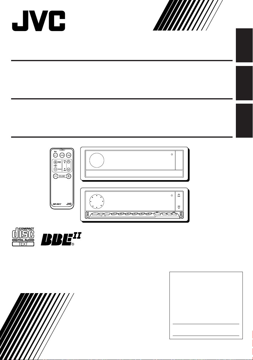
CD RECEIVER KD-LX300
ENGLISH
RECEPTOR CON CD KD-LX300
RECEPTEUR CD KD-LX300
78
MODE
SEL
DISP
SSM
10
INT RPT RNDLOCALMONOSCM
9
For installation and connections, refer to the separate manual.
Para la instalación y las conexiones, refiérase al manual separado.
Pour l’installation et les raccordements, se référer au manuel séparé.
11 12
KD-LX300
SOURCE
OFF
BAND
BBE
ESPAÑOL
FRANÇAIS
INSTRUCTIONS
MANUAL DE INSTRUCCIONES
MANUEL D’INSTRUCTIONS
For customer Use:
Enter below the Model No. and
Serial No. which are located on
the top or bottom of the cabinet.
Retain this information for future
reference.
Model No.
Serial No.
PIM163800
[J]
Page 2
INFORMATION (For U.S.A.)
This equipment has been tested and found to comply with the limits for a Class B digital device,
pursuant to Part 15 of the FCC Rules. These limits are designed to provide reasonable protection
against harmful interference in a residential installation. This equipment generates, uses, and can
radiate radio frequency energy and, if not installed and used in accordance with the instructions,
ENGLISH
may cause harmful interference to radio communications. However, there is no guarantee that
interference will not occur in a particular installation. If this equipment does cause harmful
interference to radio or television reception, which can be determined by turning the equipment off
and on, the user is encouraged to try to correct the interference by one or more of the following
measures:
– Reorient or relocate the receiving antenna.
– Increase the separation between the equipment and receiver.
– Connect the equipment into an outlet on a circuit different from that to which the receiver is
connected.
– Consult the dealer or an experienced radio/TV technician for help.
IMPORTANT FOR LASER PRODUCTS
Precautions:
1. CLASS 1 LASER PRODUCT
2. DANGER: Invisible laser radiation when open and interlock failed or defeated. Avoid direct
exposure to beam.
3. CAUTION: Do not open the top cover. There are no user-serviceable parts inside. Leave all
servicing to qualified service personnel.
4. CAUTION: This CD player uses invisible laser radiation, however, is equipped with safety switches
to prevent radiation emission when unloading CDs. It is dangerous to defeat the safety switches.
5. CAUTION: Use of controls, adjustments or performance of procedures other than those specified
herein may result in hazardous radiation exposure.
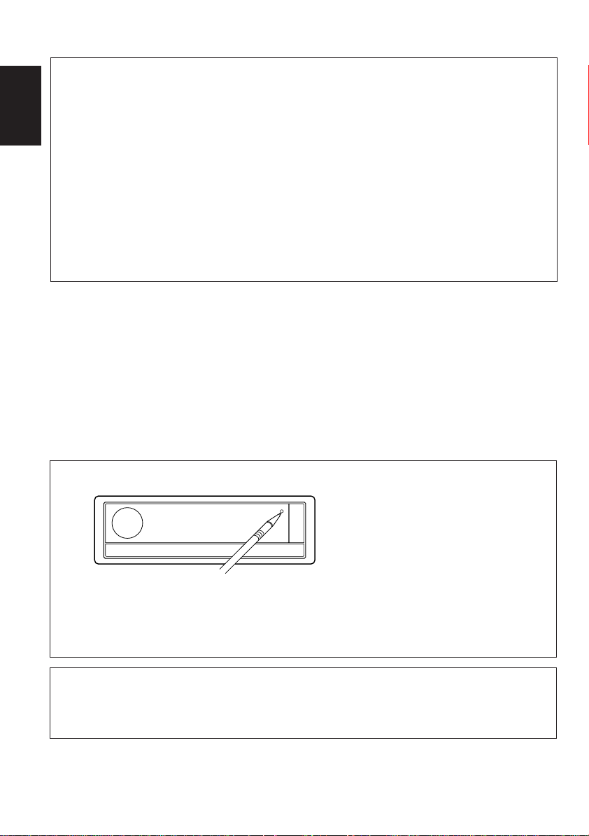
How to reset your unit
Press the reset button on the front panel using a ball-point pen or a similar tool.
This will reset the built-in microcomputer.
Note:
Your preset adjustments — such as preset channels or sound adjustments — will also be erased.
CAUTION on Volume Setting
CDs produce very little noise compared with other sources. If the volume level is adjusted for the
tuner , for example, the speak ers may be damaged by the sudden incr ease in the output level. Therefor e,
lower the volume before playing a disc and adjust it as required during playback.
2
Page 3
Thank you for purchasing a JVC product. Please read all instructions carefully before operation,
to ensure your complete understanding and to obtain the best possible performance from the unit.
CONTENTS
LOCATION OF THE BUTTONS............ 4
Control panel ........................................... 4
Remote controller .................................... 5
Preparing the remote controller ................ 6
BASIC OPERATIONS ...................... 7
RADIO BASIC OPERATIONS ............. 8
Listening to the radio ................................ 8
Storing stations in memory ....................... 9
Tuning into a preset station....................... 10
CD OPERATIONS .......................... 11
Playing a CD............................................ 11
Locating a track or a particular portion
on a CD ................................................. 12
Selecting CD playback modes.................. 12
Prohibiting CD ejection ............................. 13
Playing a CD Text .................................... 13
SOUND ADJUSTMENTS .................. 14
Adjusting the sound ................................. 14
Turning on/off the BBEII function .............. 15
Using the sound control memory.............. 15
Storing your own sound adjustments ....... 16
OTHER MAIN FUNCTIONS ............... 17
Setting the clock ...................................... 17
Changing the general settings (PSM) ...... 17
Controlling the volume automatically
(Audio Cruise) ....................................... 21
Assigning names to the sources .............. 23
CD CHANGER OPERATIONS ............. 25
Playing CDs ............................................. 25
Selecting CD playback modes ................. 26
EXTERNAL COMPONENT OPERATIONS ... 28
Playing an external component ................ 28
Using a subwoofer................................... 28
TROUBLESHOOTING...................... 29
MAINTENANCE ............................ 30
Handling CDs .......................................... 30
SPECIFICATIONS .......................... 31
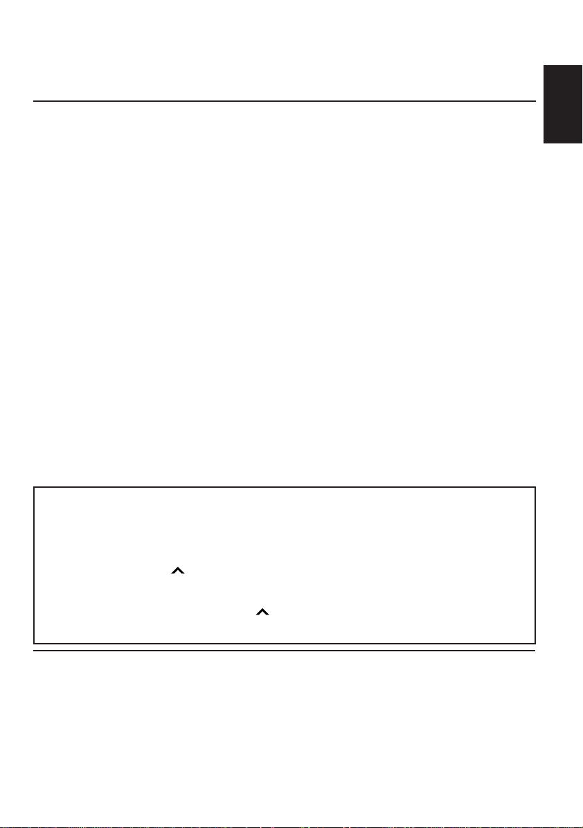
About the demonstration mode (DEMO MODE)...
When shipped from the factory, “DEMO MODE” is set to “DEMO ON” in this unit. The
demonstration will start automatically if no sound comes in for 3 minutes. (See page 21.)
To activate the display demonstration manually
While holding DISP, press ¢ until “DEMO” appears on the display.
Various functions and display illumination modes equipped with this unit will be demonstr ated repeatedly
in sequence. During the display demonstration, “DEMO” flashes on the display.
To turn off the display demonstration, press ¢ again for a few seconds while holding DISP.
• The display demonstration will turn off automatically after about 1 hour.
ENGLISH
BEFORE USE
*
For safety....
• Do not raise the volume level too much, as this will
block outside sounds, making driving dangerous.
• Stop the car before performing any complicated
operations.
*
Temperature inside the car....
If you have parked the car for a long time in hot or
cold weather, wait until the temperature in the car
becomes normal before operating the unit.
3
Page 4
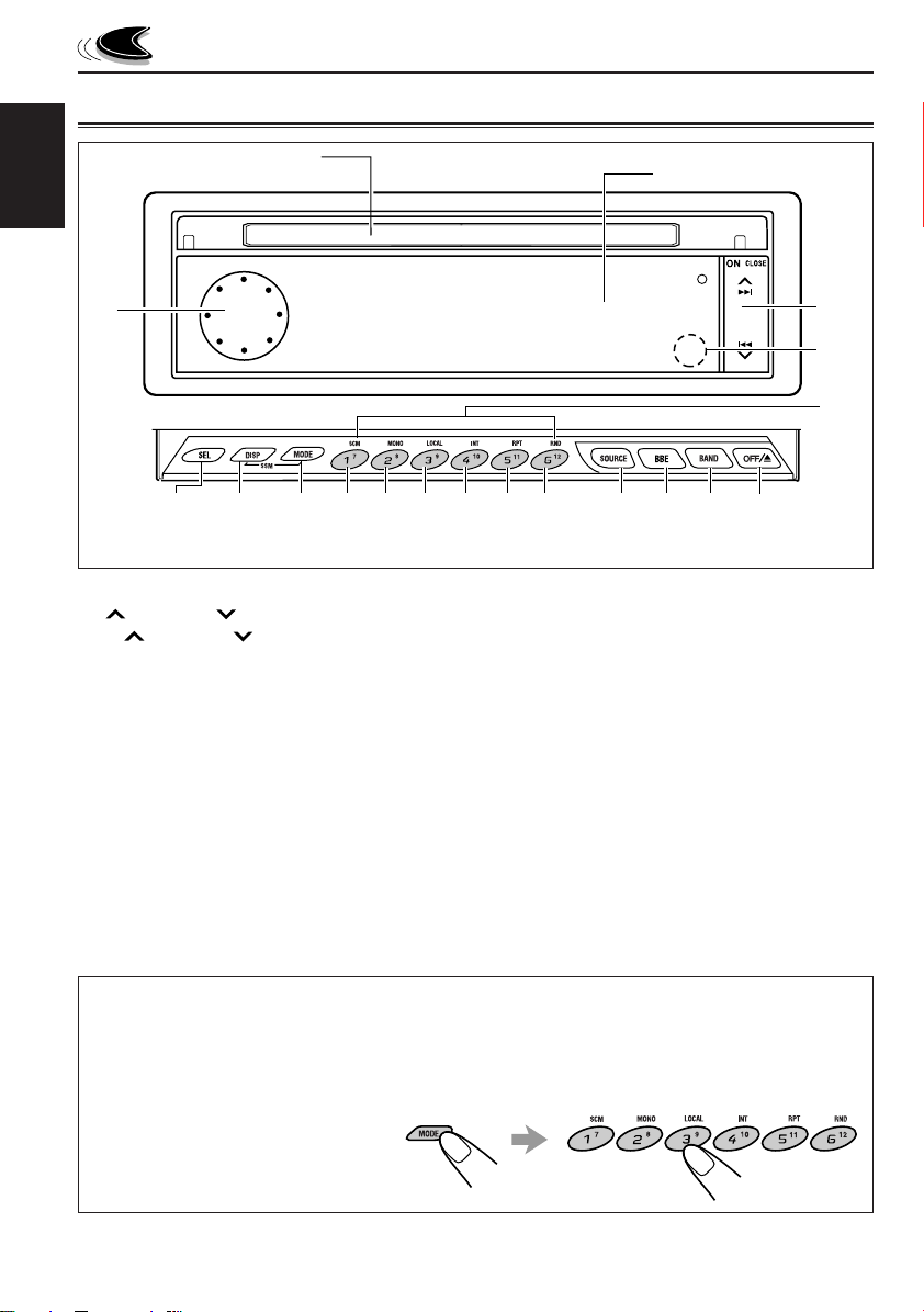
LOCATION OF THE BUTTONS
Control panel
CD loading slot
ENGLISH
1
4
1 Control dial
2
¢
/ 4 b utton
• ¢ / 4 also functions as ON or
CLOSE button.
3 Remote sensor
4 SEL (select) button
5 DISP (display) button
• Also functions as SSM buttons when pressed
together with the MODE button.
6 MODE button
• Also functions as SSM buttons when pressed
together with the DISP button.
6
5
*When you press OFF/0, the display panel moves down and the CD loading slot appears.
7
8 9
Display panel
p
*The control panel slides out when you press ON/CLOSE.
w
q
7 SCM (sound control memory) button
8 MONO button
9 LOCAL button
p INT (intro) button
q RPT (repeat) button
w RND (random) button
e SOURCE button
r BBE button
t BAND button
y OFF/0 (eject) button
u Number buttons
e
r
t y
2
3
u
How to use the number buttons:
After pressing MODE, the number buttons work as different function buttons (while “MODE” remains
on the display).
To use these buttons as number buttons after pressing MODE, wait for 5 seconds without pressing
any number button so that
“MODE” disappears from the display.
• Pressing MODE again also
erases “MODE” from the display.
4
Page 5
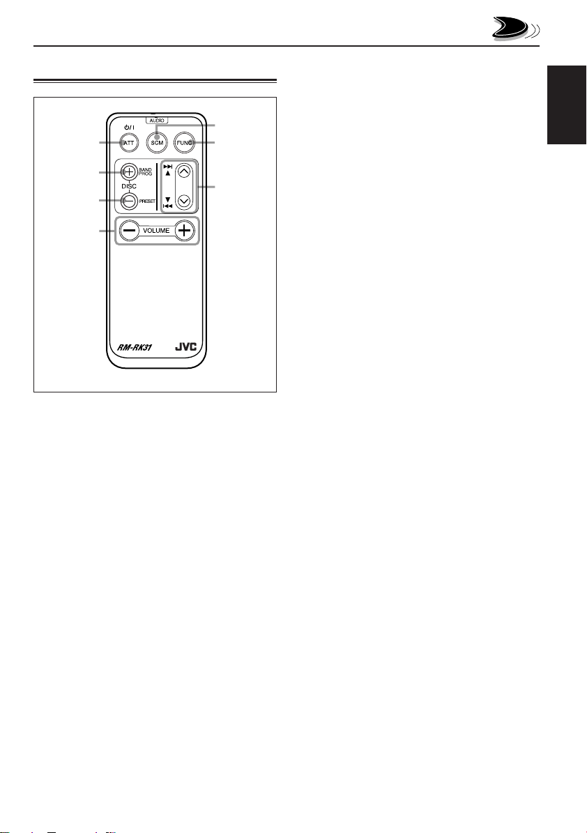
Remote controller
5
1
2
3
4
1 • Turns on the unit if pressed when the unit is
turned off.
• Turns off the unit if pressed and held until “SEE
YOU” appears on the display.
• Drops the volume level for a moment if pressed
briefly .
Press again to resume the volume.
2 • Functions as the BAND button while listening
to the radio.
Each time you press the button, the band
changes.
• Functions as the DISC + button while listening
to the CD changer.
Each time you press the button, the disc
number increases, and the selected disc starts
playing.
• Does not function as the PROG button.
6
7
3 • Functions as the PRESET button while
listening to the radio.
Each time you press the button, the preset
station number increases, and the selected
station is tuned in.
• Functions as the DISC – button while listening
to the CD changer.
Each time you press the button, the disc
number decreases, and the selected disc
starts playing.
4 Functions the same as the control dial on the
main unit.
NOTE:
This button does not function for the
preferred setting mode adjustment.
5 Selects the sound mode.
Each time you press SCM (Sound Control
Memory), the mode changes.
6 Selects the source.
Each time you press FUNC (function), the
source changes.
7 • Searches stations while listening to the radio.
• Fast-forwards or rev erses the trac k if pressed
and held while listening to a CD.
• Skips to the beginning of the next track or goes
back to the beginning of the current (or
previous) track if pressed briefly while listening
to a CD.
ENGLISH
5
Page 6
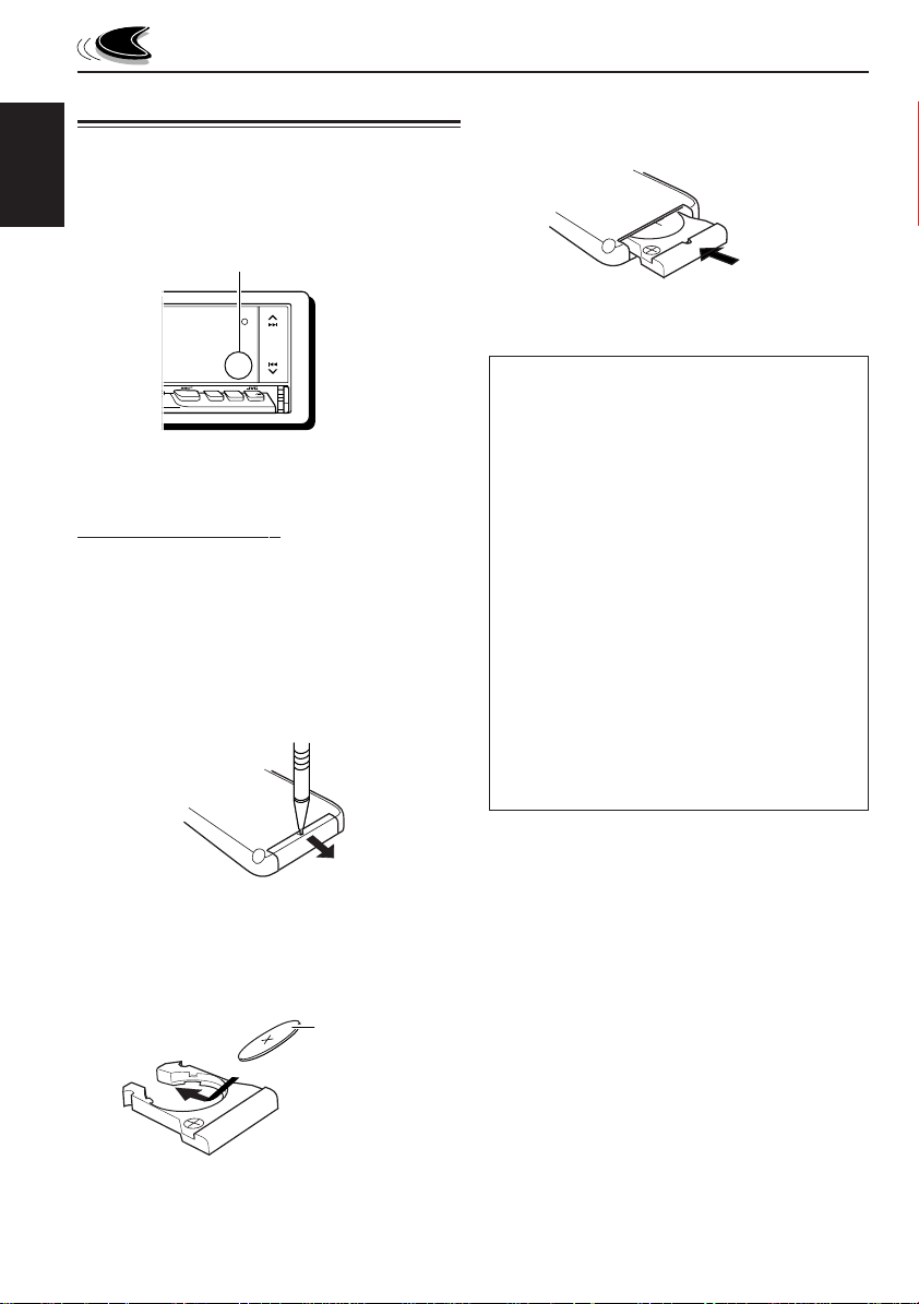
Preparing the remote controller
Before using the remote controller:
• Aim the remote controller directly at the remote
sensor on the main unit. Make sure there is no
ENGLISH
obstacle in between.
Remote sensor
3. Return the battery holder.
Insert again the battery holder pushing it until
you hear a clicking sound.
(back side)
KD-LX300
SOURCE
OFF
BAND
BBE
• Do not expose the remote sensor to strong light
(direct sunlight or artificial lighting).
Installing the battery
When the controllable range or effectiveness of the
remote controller decreases, replace the battery.
1. Remove the battery holder.
1) Push out the batter y holder in the direction
indicated by the arrow using a ball-point pen
or a similar tool.
2) Remove the battery holder.
(back side)
1)
2)
2. Place the battery.
Slide the battery into the holder with the + side
facing upwards so that the battery is fixed in the
holder.
Lithium coin battery
(product number:
CR2025)
WARNING:
• Store the batteries in a place which children
cannot reach.
If a child accidentally swallows the batteries,
immediately consult a doctor.
• Do not recharge, short, disassemble or heat the
batteries or dispose of in a fire.
Doing any of these things may cause the
batteries to give off heat, crack or start a fire.
• Do not leave the batteries with other metallic
materials.
Doing this may cause the batteries to give off
heat, crack or start a fire.
• When throwing away or saving batteries, wrap
in tape and insulate; otherwise, it may cause the
batteries to give off heat, crack or start a fire.
• Do not poke the batteries with tweezers or
similar tools.
Doing this may cause the batteries to give off
heat, crack or start a fire.
6
Page 7
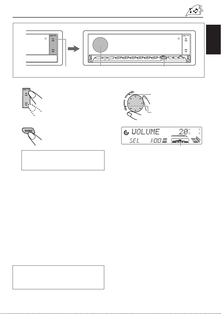
BASIC OPERATIONS
KD-LX300
SOURCE
OFF
BAND
BBE
1
1
Turn on the power.
The display illuminates and
the control panel and control
dial come out.
2
Select the source.
Each time you press the
button, the source changes
as follows:
= Tuner (FM or AM) = CD*
= CD changer** = External component
= (back to the beginning)
* If a CD is not in the loading slot, you cannot
select CD as the source to play.
** Without connecting the CD changer, you cannot
select it as the source to play.
To operate the tuner (FM or AM),
see pages 8 – 10.
To operate the CD player,
see pages 11 – 13.
To operate the CD changer,
see pages 25 – 27.
T o operate the e xternal component connected
to the LINE IN plugs, see page 28.
78
MODE
SEL
DISP
SSM
11 12
10
INT RPT RNDLOCALMONOSCM
9
KD-LX300
SOURCE
BBE
23
3
Adjust the volume.
To increase the volume.
To decrease the volume.
Volume level meter
4
Adjust the sound as you want (see
page 14).
To drop the volume in a moment
Press SOURCE for more than 1 second while
listening to any source. “ATT” starts flashing on the
display , and the volume le vel will drop in a moment.
To resume the previous volume level, press the
button for more than 1 second again.
To turn off the power
Press and hold OFF/0 until “SEE YOU” appears
on the display.
ENGLISH
OFF
BAND
Note on display illustrations:
Illustrations will differ from what appears if
“CLOCK DISP” is set to “CLK DISP OFF.” See
page 19.
Note:
When you use this unit for the first time, set the built-in
clock correctly, see page 17.
7
Page 8
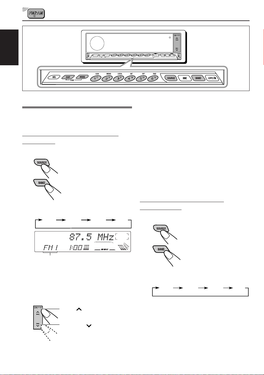
RADIO BASIC OPERATIONS
SEL
MODE
DISP
ENGLISH
SSM
Listening to the radio
You can use either automatic searching or manual
searching to tune into a particular station.
Searching a station automatically:
Auto search
1
Select the band.
1 Press SOURCE to select
tuner as the source.
2 If necessary, press BAND
repeatedly to select the
band.
Each time you press the button, the band
changes as follows:
FM1 FM2 FM3 AM
Selected band appears.
Note:
This receiver has three FM bands (FM1, FM2,
FM3). You can use any one of them to listen to an
FM broadcast.
78
INT RPT RNDLOCALMONOSCM
9
10
11 12
KD-LX300
SOURCE
OFF
BAND
BBE
To stop searching before a station is received,
press the same button you have pressed for
searching.
To tune in FM stations only with strong signals
1 Press MODE.
“MODE” appears on the display, and the number
buttons can work as different function buttons.
2 Press LOCAL, while “MODE” is still on the display ,
so that the LOCAL indicator lights up on the
display.
This function works only while searching FM
stations, including SSM preset (see page 9).
Each time you press the button, the LOCAL
indicator lights up and goes off alternately.
Searching a station manually:
Manual search
1
Select the band.
1 Press SOURCE to select
tuner as the source.
2 If necessary, press BAND
repeatedly to select the
band.
Each time you press the button, the band
changes as follows:
FM1 FM2 FM3 AM
2
Start searching a station.
When a station is received, searching
stops.
8
Press ¢ to search
stations of higher frequencies.
Press 4 to search
stations of lower frequencies.
Note:
This receiver has three FM bands (FM1, FM2,
FM3). You can use any one of them to listen to an
FM broadcast.
Page 9
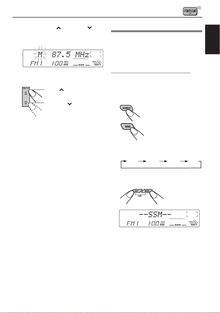
2
Press and hold ¢ or 4 until
“M” (manual) starts flashing on the
display.
3
T une into a station you want while “M”
is flashing.
Press ¢ to tune into
stations of higher frequencies.
Press 4 to tune into
stations of lower frequencies.
• If you release your finger from the button,
the manual mode will automatically turn off
after 5 seconds.
• If you hold down the button, the frequency
keeps changing until you release the button.
When an FM stereo broadcast is hard to
receive:
1 Press MODE while listening to an FM stereo
broadcast (the ST indicator lights up while
receiving an FM stereo broadcast).
2 Press MONO, while “MODE” is still on the displa y ,
so that the MO indicator lights up on the display.
The sound you hear becomes monaural but the
reception will be improved (the ST indicator goes
off).
Each time you press the button, the MO indicator
lights up and goes off alternately .
Storing stations in memory
You can use one of the following two methods to
store broadcasting stations in memory.
• Automatic preset of FM stations: SSM (Strongstation Sequential Memory)
• Manual preset of both FM and AM stations
FM station automatic preset: SSM
Y ou can preset 6 local FM stations in each FM band
(FM1, FM2 and FM3).
1
Select the FM band (FM1–3) you want
to store FM stations into.
1 Press SOURCE to select
tuner as the source.
2 If necessary, press
BAND repeatedly to
select the band.
Each time you press the button, the band
changes as follows:
FM1 FM2 FM3 AM
2
Press and hold both buttons for more
than 2 seconds.
ENGLISH
“SSM” appears, then disappears when automatic
preset is over.
Local FM stations with the strongest signals are
searched and stored automatically in the band
number you have selected (FM1, FM2 or FM3).
These stations are preset in the number buttons
— No.1 (lowest frequency) to No.6 (highest
frequency).
When automatic preset is over, the station stored
in number button 1 will be automatically tuned in.
9
Page 10
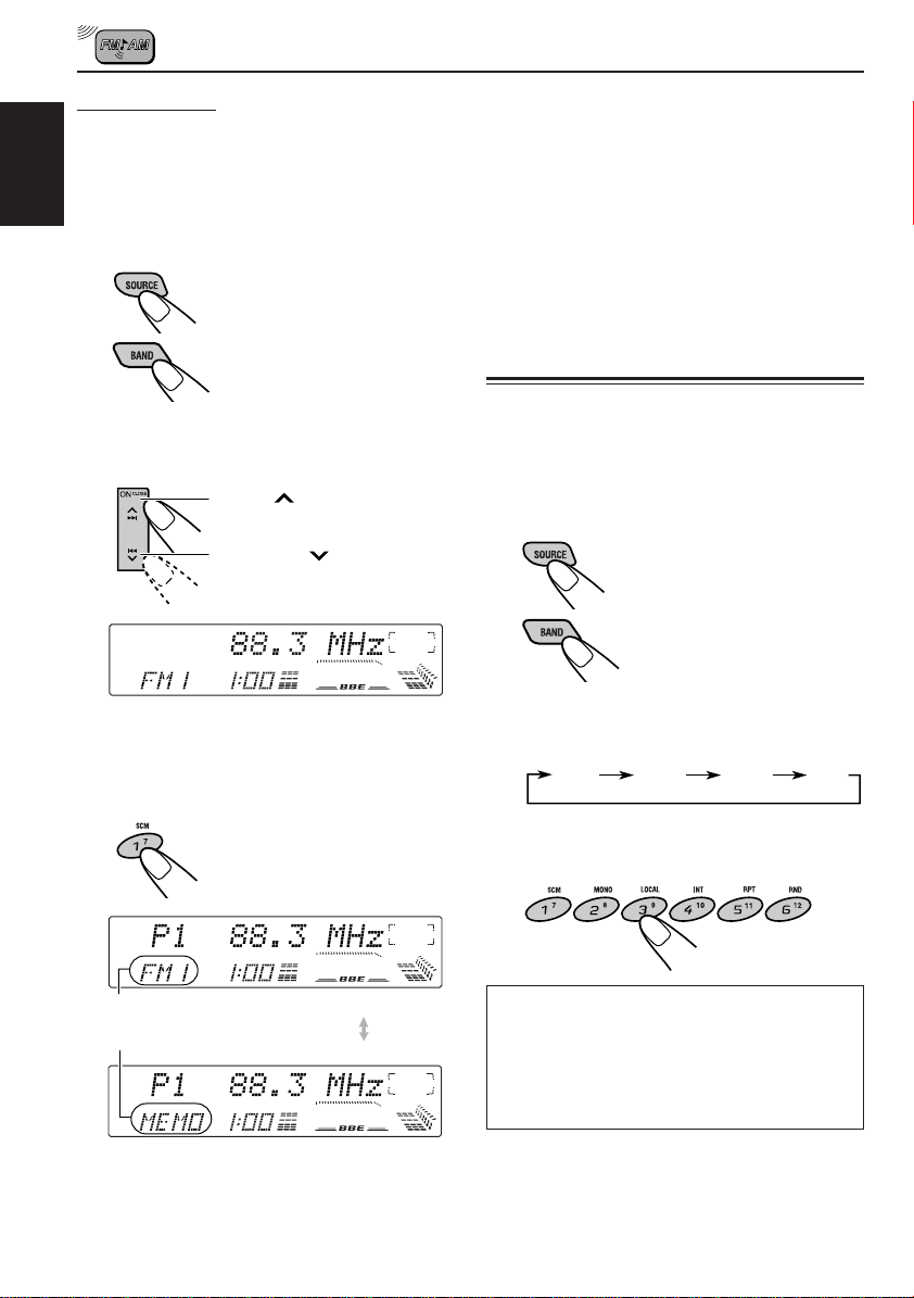
Manual preset
Y ou can preset up to 6 stations in each band (FM1,
FM2, FM3 and AM) manually.
Ex.: Storing an FM station of 88.3 MHz into the
ENGLISH
preset number 1 of the FM1 band
1
Select the band (FM1).
1 Press SOURCE to
select the tuner as the
source.
2 Press BAND repeatedly
to select the FM1 band.
2
Tune into a station of 88.3 MHz.
Press ¢ to tune into
stations of higher frequencies.
Press 4 to tune into
stations of lower frequencies.
3
Press and hold the number button (in
this example, 1) for more than 2
seconds.
4
Repeat the above procedure to store
other stations into other preset
numbers.
Notes:
• A previously preset station is erased when a new station
is stored in the same preset number.
• Preset stations are erased when the power supply to the
memory circuit is interrupted (for example, during battery
replacement). If this occurs, pr eset the stations again.
Tuning into a preset station
You can easily tune into a preset station.
Remember that you must store stations first. If you
have not stored them yet, see “Storing stations in
memory” on pages 9 and 10.
1
Select the band.
1 Press SOURCE to select
tuner as the source.
2 If necessary, press
BAND repeatedly to
select the band.
Each time you press the button, the band
changes as follows:
FM1 FM2 FM3 AM
2
Select the number (1 – 6) for the preset
station you want.
10
Band number and “MEMO” appear
alternately for a while.
When using this unit in an area other than
North or South America:
You need to change the AM/FM channel
intervals. See “To change the AM/FM
channel intervals – AREA CHANGE” on
page 20.
Page 11
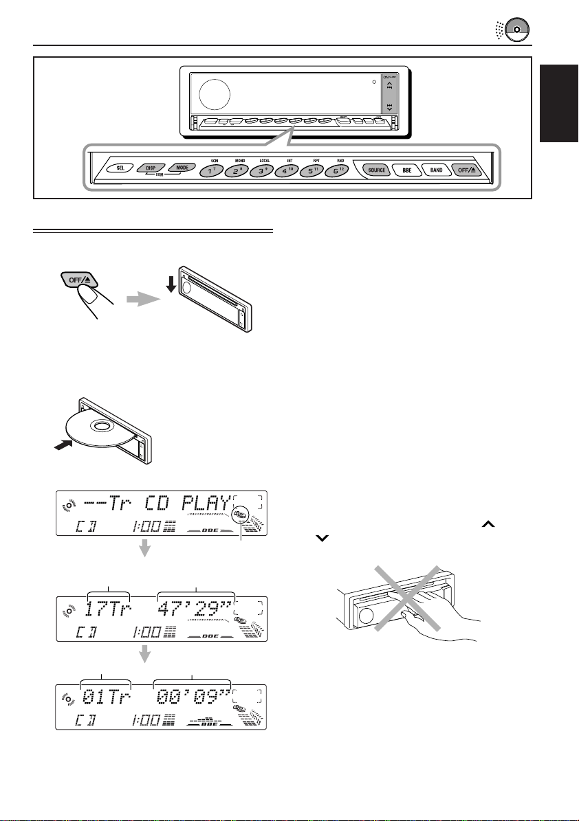
CD OPERATIONS
Playing a CD
1
Open the loading slot.
The display panel moves down, and the
loading slot appears.
2
Insert a disc into the loading slot.
The unit draws in a CD,
the display panel
moves up, and CD play
starts automatically.
The CD indicator lights up.
Total track number of
the inserted disc
Total playing time of the
inserted disc
78
MODE
SEL
DISP
SSM
10
INT RPT RNDLOCALMONOSCM
9
11 12
KD-LX300
SOURCE
OFF
BAND
BBE
ENGLISH
Notes:
• When a CD is in the loading slot, selecting “CD”
as the source by pressing SOURCE starts CD play.
• When a CD is inserted upside down, the CD
automatically ejects. (“DISC EJECT” appears on
the display.)
• When you play a CD Text, the disc title and
performer appear on the display. Then the current
track title appears on the display, followed by the
track number and elapsed playing time. See also
“Playing a CD Text” (page 13) and “To select the
scroll mode – SCROLL MODE” (page 20).
If a CD Text includes much text information, some
may not appear on the display.
• If you change the source, CD play also stops
(without ejecting the CD).
To stop play and eject the CD
Press OFF/0 briefly.
CD play stops, the display panel moves down,
then the CD automatically ejects from the loading
slot.
To move up the display panel, press ¢ or
4 . If no button is pressed, the display
panel will move up in about 5 minutes.
Current track
Elapsed playing time
CAUTION: NEVER insert your finger between
the display panel and the unit, as it
may get caught in the unit.
Note:
If the ejected disc is not removed for about 15
seconds, the disc is automatically inserted again into
the loading slot to protect it from dust. (CD play will
not start this time.)
11
Page 12
Locating a track or a
particular portion on a CD
To fast-forward or reverse the track
ENGLISH
Press and hold ¢, while
playing a CD, to fast-forward
the track.
Press and hold4 , while
playing a CD, to reverse the
track.
To go to the next tracks or the previous
tracks
Press ¢ briefly, while
playing a CD, to go ahead to
the beginning of the next track.
Each time you press the button
consecutively, the beginning of
the next tracks is located and
played back.
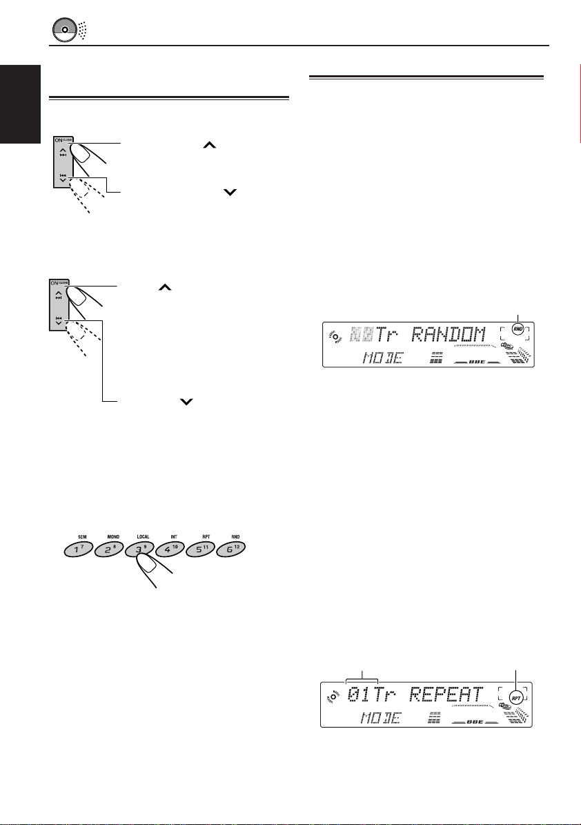
Selecting CD playback modes
To play back tracks at random (Random
Play)
You can play back all tracks on the CD at
random.
1 Press MODE while playing a CD.
“MODE” appears on the lower part of the
display, and the number buttons can work as
different function buttons.
2 Press RND (Random), while “MODE” is still
on the display, so that the RND indicator lights
up on the display.
Each time you press the button, CD random
play mode turns on and off alternately.
The RND indicator
Press 4 briefly, while
playing a CD, to go back to the
beginning of the current track.
Each time you press the button
consecutively, the beginning of
the previous tracks is located
and played back.
To go to a particular track directly
Press the number button corresponding to the
track number to start its playback.
• To select a track number from 1 – 6:
Press 1 (7) – 6 (12) briefly.
• To select a track number from 7 – 12:
Press and hold 1 (7) – 6 (12) for more than 1
second.
12
When the random mode is turned on, the RND
indicator lights up on the display and a track
randomly selected starts playing.
To play back tracks repeatedly (Repeat
Play)
You can play back the current track repeatedly.
1 Press MODE while playing a CD.
“MODE” appears on the lower part of the
display, and the number buttons can work as
different function buttons.
2 Press RPT (Repeat), while “MODE” is still on
the display, so that the RPT indicator lights up
on the display.
Each time you press the button, CD repeat
play mode turns on and off alternately.
Track number of the
currently playing track
When the repeat mode is turned on, the RPT
indicator lights up on the display.
The RPT indicator
Page 13
To play back only intros (Intro Scan)
You can play back the first 15 seconds of each
track sequentially.
1 Press MODE while playing a CD.
“MODE” appears on the lower part of the
display, and the number buttons can work as
different function buttons.
2 Press INT (Intro), while “MODE” is still on the
display.
Each time you press the button, CD intro scan
mode turns on and off alternately.
Track number of the currently playing track
Playing a CD Text
In a CD Text, some information about the disc (its
disc title, performer and track title) is recorded.
You can show these disc information on the
display.
Select text display mode while playing a
CD Text.
Each time you press the button, the display
changes as follows:
ENGLISH
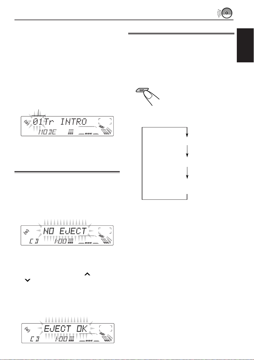
When the intro scan mode is turned on, “INTRO”
appears on the display for 5 seconds and the
track number flashes.
Prohibiting CD ejection
You can prohibit CD ejection and can lock a CD
in the loading slot.
While pressing SOURCE, press and hold OFF/0
for more than 2 seconds. “NO EJECT” flashes on
the display for about 5 seconds, and the CD is
locked and cannot be ejected.
Note:
If you press OFF/0 while CD ejection is pr ohibited , the
control panel moves down, but the CD cannot be ejected.
(“NO EJECT” appears on the display.)
To move up the display panel, press ¢ or
4 .
To cancel the prohibition and unlock the CD,
press and hold OFF/0 for more than 2 seconds
again, while pressing SOURCE. “EJECT OK”
flashes on the display for about 5 seconds, and
the CD is unlocked.
Disc Title / Performer
Track Title
Current track no. and
Elapsed playing time
Notes:
• The display shows up to 12 characters at one time
and scrolls if there are more than 12 characters.
See also “To select the scroll mode – SCROLL
MODE” on page 20.
• When you press DISP while playing a conventional
CD, “NO NAME” appears for the disc title/
performer and the track title.
13
Page 14
SOUND ADJUSTMENTS
Adjusting the sound
You can adjust the sound characteristics to your
preference.
ENGLISH
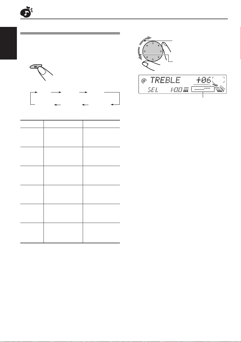
1
Select the item you want to adjust.
Each time you press the
button, the adjustable items
change as follows:
BASS
VOLUME
Indication To do: Range
BASS Adjust the bass. –06 (min.)
TREBLE Adjust the treble. –06 (min.)
FADER* Adjust the front R06 (Rear only)
BALANCE Adjust the left L06 (Left only)
WOOFER Adjust the 00 (min.)
VOLUME Adjust the volume. 00 (min.)
TREBLE
and rear speaker |
balance. F06 (Front only)
and right speaker |
balance. R06 (Right only)
subwoofer output |
level. 08 (max.)
FADER
BALANCEWOOFER
|
+06 (max.)
|
+06 (max.)
|
50 (max.)
2
Adjust the level.
To increase the level.
To decrease the level.
Equalization pattern changes as you adjust
the bass or treble.
Note:
Normally the control dial works for volume
adjustment. So you do not have to select “VOLUME”
to adjust the volume level.
* If you are using a two-speaker system, set the fader
level to “00.”
14
Page 15
Turning on/off the BBE
function
II
Using the sound control
memory
The BBEII* function restores the brilliance and clarity
of the original live sound in recording, broadcasts,
etc.
When a speaker reproduces sound, it introduces
frequency-dependent phase shifting, causing highfrequency sounds to take longer to reach the ear
than low frequency sounds. The BBEII function
adjusts the phase relationship between the low , mid
and high frequencies by adding a progressively
longer delay time to the low and mid frequencies,
so that all frequencies reach the listener’s ears at
the proper time.
In addition, the BBEII function boosts low and high
frequencies, which loudspeakers tend to be less
efficient in reproducing, through dynamic, programdriven augmentation. When combined with the
phase compensation feature, the resulting sound
has a clearer, more finely detailed “live” presence.
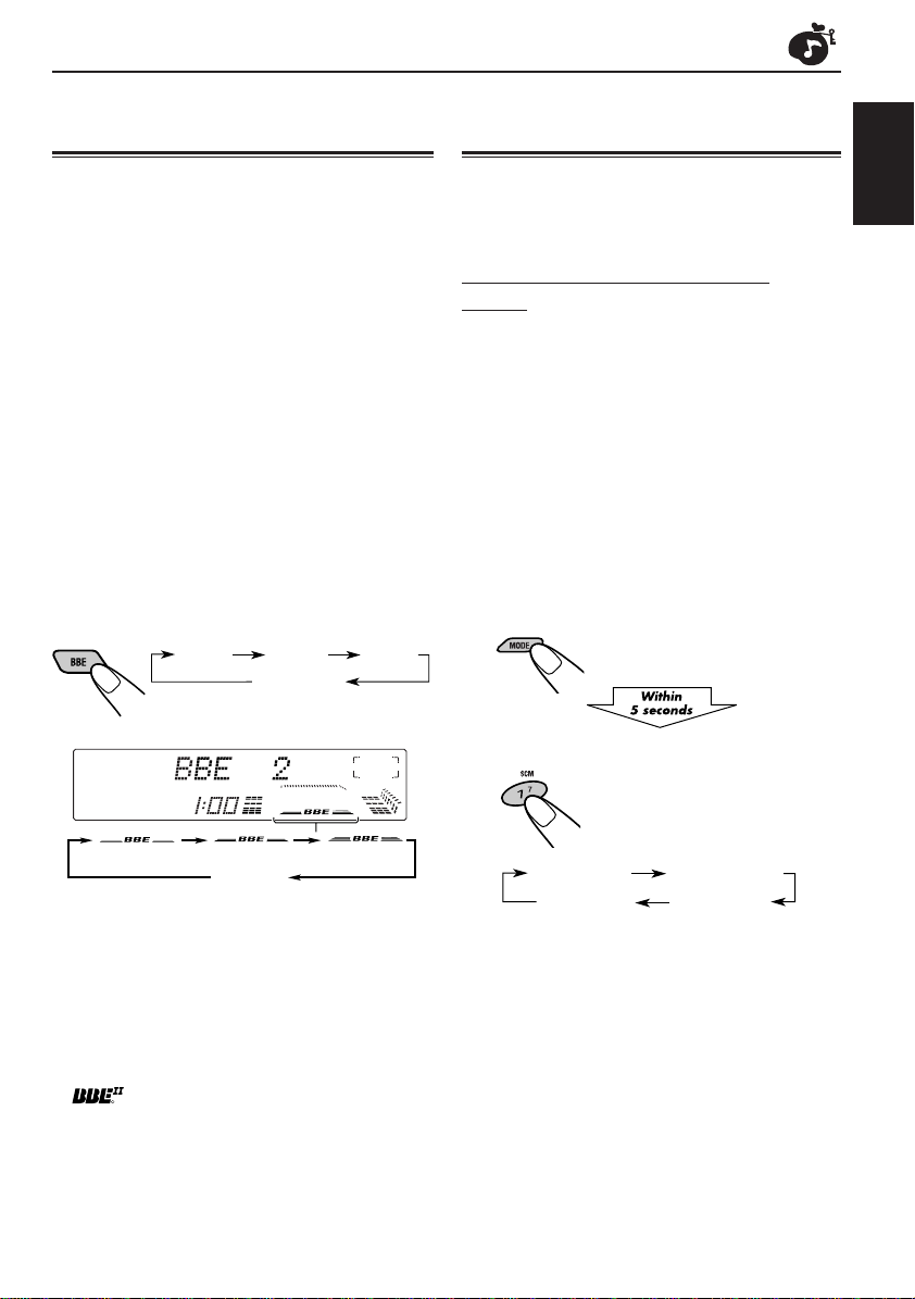
Each time you press BBE, the BBEII function
changes as follows:
BBE 1 BBE 2
BBE 3
BBE OFF
(Canceled)
(1) (2)
As the number gets higher, the BBEII function
becomes stronger.
When shipped from the factory, the BBEII function
is set to “BBE 2.”
To cancel the BBEII function, select “BBE OFF.”
* Under license from BBE Sound, Inc.
R
is a trademark of BBE Sound, Inc.
Canceled
(OFF)
(3)
You can select and store a preset sound
adjustment suitable for each playback source.
(Advanced SCM)
Selecting and storing the sound
modes
Once you select a sound mode, it is stored in
memory. It will be recalled every time you select
the same source and will be shown on the
display.
A sound mode can be stored for each of the
following sources — FM1, FM2, FM3, AM, CD
and external components.
• If you do not want to store the sound mode
separately for each playback source, but want
to use the same sound mode for all the
sources, see “To cancel Advanced SCM
– SCM LINK” on page 19.
1
Press MODE.
The number buttons can work
as different function buttons.
2
Select the sound mode you want.
Each time you press the
button, the sound mode
changes as follows:
SCM BEAT SCM SOFT
SCM OFF
• When “SCM LINK” is set to “SCM LINK ON,” the
selected sound mode can be stored in memory
for the current source and the effect applies only
to the current source. Each time you change the
playback source, the SCM indicator flashes on
the display.
• When “SCM LINK” is set to “SCM LINK OFF,”
the selected sound mode effect applies to any
source.
SCM POP
ENGLISH
CONTINUED ON THE NEXT PAGE
15
Page 16
Indication For: Preset values
Bass Treble BBE
SCM BEAT Rock or disco +02 00 2
music
SCM SOFT Quiet +01 –03 OFF
ENGLISH
SCM POP Light music +04 +01 OFF
SCM OFF (Flat sound) 00 00 2
background
music
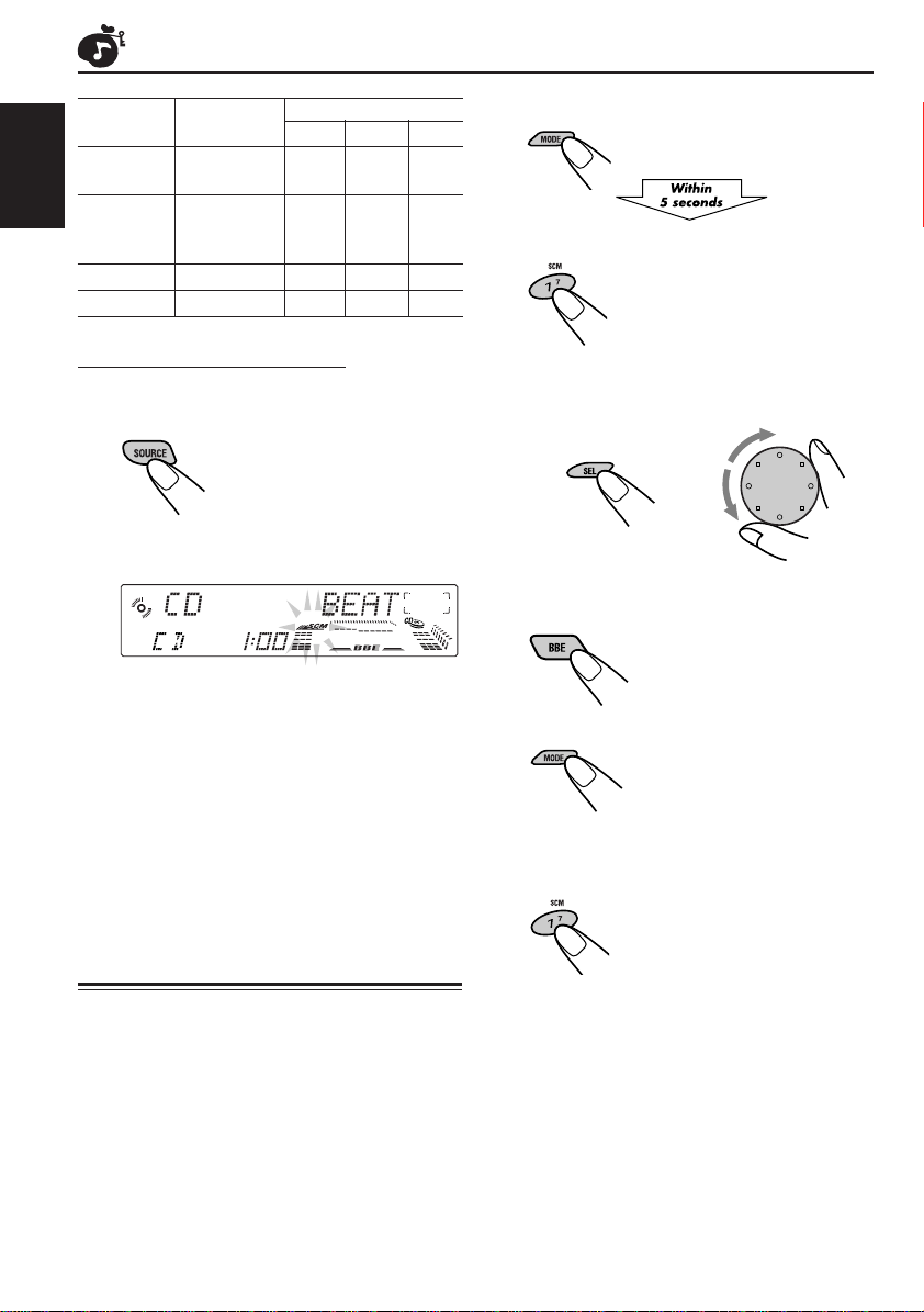
1
II
Press MODE.
The number buttons can work as
different function buttons.
2
Select the sound mode you want.
For details, see page 15.
Recalling the sound modes
When “SCM LINK” is set to “SCM LINK
ON,” select the source.
The sound mode stored in memory for the
selected source is recalled.
Notes:
• You can adjust each sound mode to your preference,
and store it in memory.
If you want to adjust and store your original sound
mode, see “Storing your own sound adjustments”
below.
• To adjust the bass and treble reinforcement levels or
to turn on/off the BBEII function temporarily, see
pages 14 and 15. (Your adjustments will be
canceled if another source is selected.)
Storing your own sound
adjustments
You can adjust the sound modes (SCM BEAT,
SCM SOFT, SCM POP) to your preference and
store your own adjustments in memory.
• There is a time limit in doing the following
procedure. If the setting is canceled before you
finish, start from step 1 again.
3
1 Select the item you want to adjust
(BASS or TREBLE).
2 Adjust the selected item.
21
Repeat step 3 to adjust the other items.
To adjust the BBEII level, see page 15.
4
Press MODE.
5
Press and hold SCM until the sound
mode you have selected flashes on
the display.
Your adjustment made for the
selected sound mode is stored in
memory.
6
Repeat the same procedure to
adjust other sound modes.
To reset to the factory settings
Repeat the same procedure and reassign the
preset values listed in the table on the left column.
16
Page 17

OTHER MAIN FUNCTIONS
Setting the clock
1
Press and hold SEL (select) for
more than 2 seconds so that one of
the PSM items appears on the
display. (See page 18.)
2
Set the hour.
1 Select “CLOCK HOUR” if not shown on
the display.
2 Adjust the hour.
1
3
Set the minute.
1 Select “CLOCK MINUTE.”
2 Adjust the minute.
1
2
2
Changing the general settings
(PSM)
You can change the items listed on the next page
by using the PSM (Preferred Setting Mode) control.
Basic Procedure
1
Press and hold SEL (select) for more
than 2 seconds so that one of the
PSM items appears on the display.
(See page 18.)
2
Select a PSM item you want to adjust.
(See page 18.)
3
Adjust the PSM item selected above.
ENGLISH
4
Press SEL (select) to finish the setting.
4
Repeat steps 2 and 3 to adjust the
other PSM items if necessary.
5
Press SEL (select) to finish the setting.
17
Page 18
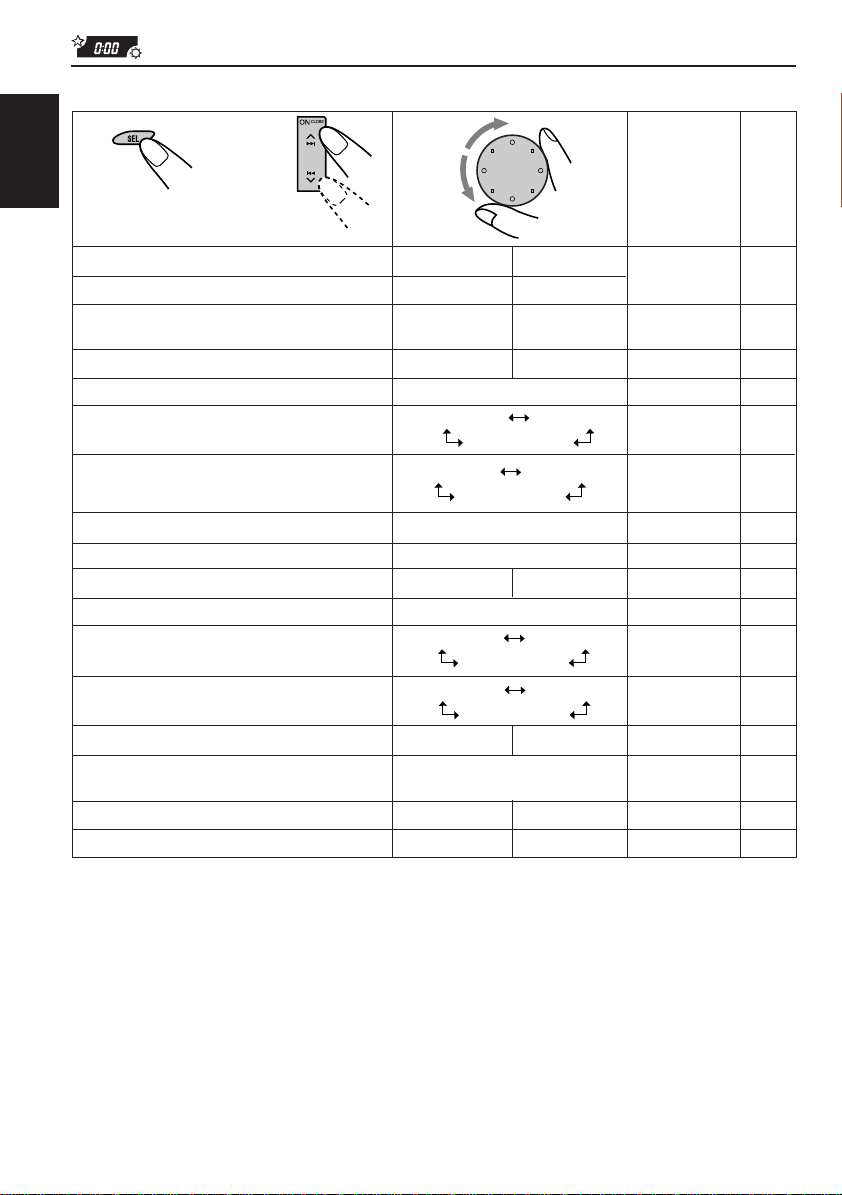
Preferred Setting Mode (PSM) items
1
ENGLISH
Hold.
CLOCK HOUR Hour adjustment
CLOCK MINUTE Minute adjustment
SCM LINK Sound control
CLOCK DISP Clock display
LEVEL METER Level display
DIMMER MODE Dimmer mode
CRUISE MODE Audio cruise
+OR– RPM SET* Idling speed
BOOST* Boost
BEEP SWITCH Key-touch tone
CONTRAST Display contrast
SCROLL MODE Scroll mode
WOOFER FREQ Subwoofer cutoff
AREA CHANGE Channel interval
LINE ADJ Line input level
FLAT PANEL Flat panel
DEMO MODE Demo mode
2
Select.
memory linkage
frequency
adjustment
3
Set.
Counterclockwise
Back Advance
SCM LINK OFF
4 types (see page 19) NORMAL 19
DIMMER AUTO
DIMMER ON
CRUISE 1
CRUISE OFF
BOOST 01 – 15 BOOST 05
BEEP OFF BEEP ON
CONTRAST 01 – 10
SCROLL ONCE
SCROLL OFF
FREQ LOW FREQ MID
FREQ HIGH
AREA US AREA EU
LINE ADJ 00 – 05
DEMO OFF DEMO ON DEMO ON 21
Clockwise
AdvanceBack
CLK DISP ONCLK DISP OFF
DIMMER OFF
CRUISE 2
—
SCROLL AUTO
Factory-preset
settings
1:00 17
SCM LINK ONSCM LINK ON
CLK DISP ON
DIMMER AUTO
CRUISE OFF
800 rpm
BEEP ON
CONTRAST 05
SCROLL ONCE
FREQ MID
AREA US
LINE ADJ 00
FLAT OFF
See
page
19
19
19
21
22
22
19
19
20
20
20
20
21FLAT ONFLAT OFF
4
Press SEL (select) to finish the setting.
* When you select “CRUISE 1” or “CRUISE 2” for Audio Cruise Mode, you can adjust these items.
18
Page 19

To cancel Advanced SCM — SCM LINK
You can cancel the Advanced SCM (Sound
Control Memory), and unlink the sound modes
and the playback sources
When shipped from the factory, a different sound
mode can be stored in memory for each source
so that you can change the sound modes simply
by changing the sources.
• SCM LINK ON: Advanced SCM (different
sound modes for different
sources)
• SCM LINK OFF: Conventional SCM (one
sound mode for all sources)
To set the clock display — CLOCK DISP
You can set the clock to be shown on the lower
part of the display when the unit is turned on.
When shipped from the factory, the clock is set to
be shown on the display.
• CLK DISP ON: Clock display is turned on.
• CLK DISP OFF: Clock display is turned off.
When “CLK DISP OFF” is
selected, the current sound
mode setting (see page 15) is
shown on the upper part of
the display*.
To select the dimmer mode
— DIMMER MODE
When you turn on the car headlights, the display
automatically dims (Auto Dimmer).
When shipped from the factory, Auto Dimmer
mode is activated.
• DIMMER AUTO: Activates Auto Dimmer.
• DIMMER OFF: Cancels Auto Dimmer.
• DIMMER ON: Always dims the display.
Note on Auto Dimmer:
Auto Dimmer equipped with this unit may not work
correctly on some vehicles, particularly on those
having a control dial for dimming.
In this case, set the dimmer mode to “DIMMER ON”
or “DIMMER OFF.”
To turn on/off the key-touch tone
— BEEP SWITCH
You can deactivate the key-touch tone if you do
not want it to beep each time you press a button.
When shipped from the factory, the key-touch
tone is activated.
• BEEP ON: Activates the key-touch tone.
• BEEP OFF: Deactivates the key-touch
tone.
ENGLISH
* If an external source is selected, the current sound
mode setting is shown on the lower part of the
display.
To select the level meter — LEVEL METER
You can select the level meter display according
to your preference. When shipped from the
factory, “NORMAL” is selected.
• NORMAL: Normal audio level meter
(illuminates from bottom to
top).
• MIRROR: Level meter illuminates as if it
were reflected on a mirror.
• LEVEL OFF: Volume level meter stays lit
and does not change its
illumination.
• ALL OFF: Level meter turns off.
To adjust the display contrast level
— CONTRAST
You can adjust the display contrast level among
“01” (dark) to “10” (bright). When shipped from
the factory, the display contrast level is set at
level “05.”
19
Page 20

To select the scroll mode — SCROLL MODE
You can select the scroll mode for the disc
information if it consists of more than 12
characters. When shipped from the factory, Auto
Scroll mode is set to “SCROLL ONCE.”
ENGLISH
• SCROLL ONCE:Scrolls only once.
• SCROLL AUTO: Repeats the scroll
• SCROLL OFF: Cancels Auto Scroll.
Note:
Even if the scroll mode is set to “SCROLL OFF,” you
can scroll the display by pressing DISP for more than
1 second.
(in 5-second intervals).
To select the subwoofer cutoff frequency
— WOOFER FREQ
When a subwoofer is connected to this unit,
select an appropriate cutoff frequency level for
your subwoofer. When shipped from the factory,
the subwoofer cutoff frequency is set to “FREQ
MID.”
• FREQ LOW: Frequencies higher than
50 Hz are cut off to the
• FREQ MID: Frequencies higher than
• FREQ HIGH: Frequencies higher than
subwoofer.
80 Hz are cut off to the
subwoofer.
120 Hz are cut off to the
subwoofer.
To change the AM/FM channel intervals
— AREA CHANGE
When this unit is shipped from the factory, the
channel intervals are set to 10 kHz for AM and
200 kHz for FM (AREA US settings).
You will have to change the channel intervals
when using this unit in an area other than North
America and South America.
• AREA EU: Select this when using this
unit in an area other than
North and South America.
(9 kHz for AM and 50 kHz (for
manual tuning) / 100 kHz (for
searching) for FM)
• AREA US: Select this when using this
unit in North or South
America. (10 kHz for AM and
200 kHz for FM)
Note:
If the channel intervals settings are changed, the
following will occur.
• The names assigned to the stations will be erased
from memory. To reassign the names, see
“Assigning names to the sources” on pages
23 – 24.
To adjust the line input level — LINE ADJ
Adjust the line input level properly when an
external component is connected to the LINE IN
plugs. When shipped from the factory, the line
input level is set at level “00.”
If the input level of the connected component is
not high enough, increase the input level
properly. Without adjusting the line input level,
you may be surprised at a loud sound when you
change from the external component to another
source.
20
Page 21
To make the front panel look flat (hiding
the control panel) — FLAT PANEL
When operating the receiver using the remote
control, you can hide the control panel to make
the front panel look flat. When shipped from the
factory, “FLAT OFF” is selected.
• FLAT ON: The control panel will not
come out when you turn on
the unit.
To use the control panel,
press 4 so that the
control panel comes out. If no
operation is done for about
10 seconds, it automatically
goes back into the receiver.
• FLAT OFF: You can use the control panel
normally.
Note:
When “FLAT ON” is selected, you can eject a CD by
holding 4 .
To turn the demo mode on or off
— DEMO MODE
You can turn the demo mode on or off. When
shipped from the factory, “DEMO ON” is
selected.
• DEMO ON: Turns the demo mode on.
The demonstration will start
automatically if no sound
comes in for 3 minutes.
• DEMO OFF: Turns the demo mode off.
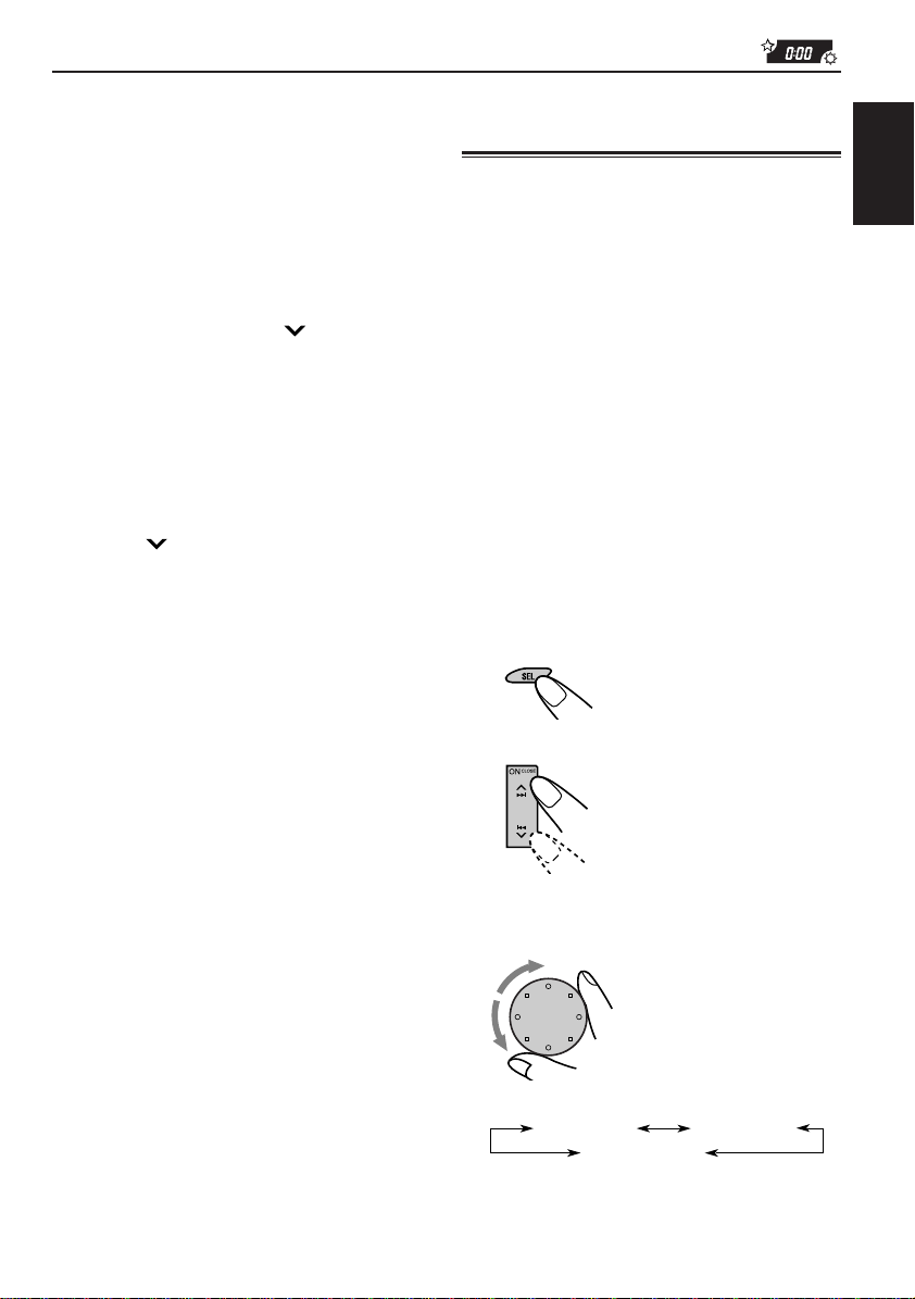
Controlling the volume
automatically (Audio Cruise)
You can select the proper cruise mode for your
car.
This unit changes the volume level automatically
(at 3 possible levels) based on the driving speed
of your car by detecting the alternator’s
generating frequency (Audio Cruise).
If you want to use this mode, follow the
procedure below. When shipped from the factory,
this mode is set to “CRUISE OFF.”
• CRUISE 1: Select this if your car is
• CRUISE 2: Select this if your car is
• CRUISE OFF: Cancels Audio Cruise.
1
Press and hold SEL (Select) for
more than 2 seconds so that one of
the PSM items appears on the
display. (See page 18.)
2
Select “CRUISE MODE.”
relatively quiet.
relatively loud.
The volume increase rate is
twice as much as that of the
CRUISE 1 setting.
ENGLISH
Note:
If the unit has been reset (and the power is on),
demonstration will start if no sound comes in for
about 10 seconds.
3
Select the desired setting.
As you turn the control dial, the Audio
Cruise mode changes as follows:
CRUISE 1
CRUISE OFF
CONTINUED ON NEXT PAGE
CRUISE 2
21
Page 22
4
Press SEL (select) to finish the
setting.
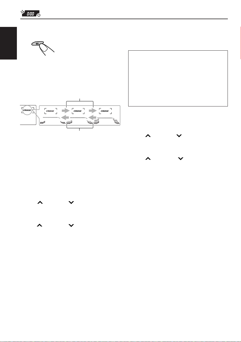
If Audio Cruise does not function correctly
You may need to store the idling speed into
memory to make Audio Cruise function correctly.
ENGLISH
When this function is turned on (the CRUISE
indicator lights up on the display), the proper
volume level is automatically selected among the
3 possible levels according to the driving speed,
and the selected level is shown on the display.
When the driving speed increases.
When the driving speed decreases.
To adjust the volume increase rate
If you find Audio Cruise increases (or decreases)
the volume either too much or too little as the
driving speed changes, you can adjust the
increase rate by changing the boost lev el.
To change it, follow the procedure below.
1 Press and hold SEL (select) for more than 2
seconds so that one of the PSM items appears
on the display.
2 Press ¢ or 4 repeatedly until
“CRUISE MODE” appears on the display.
3 Turn the control dial to select either “CRUISE
1” or “CRUISE 2.”
4 Press ¢ (or 4 ) to select “BOOST.”
The current boost level also appears on the
display.
5 Turn the control dial to select the desired boost
level (among 01 to 15).
6 Press SEL (select) to finish the setting.
NOTICE that a number of factors, such as
electric power steering, wipers, power
windows, air conditioner, etc. do generate
noises and, as a result, may cause Audio
Cruise not to function correctly. If this is the
main cause of malfunction, connect the
memory backup lead (yellow lead) directly to
the car battery to prevent these noises from
affecting Audio Cruise.
1 Start the engine and let it warm up.
2 Press and hold SEL (select) for more than 2
seconds so that one of the PSM items appears
on the display.
3 Press ¢ or 4 repeatedly until
“CRUISE MODE” appears on the display.
4 Turn the control dial to select either “CRUISE
1” or “CRUISE 2.”
5 Press ¢ (or 4 ) to select “+OR–
RPM SET.”
6 Turn the control dial to select the desired idling
speed.
7 Press SEL (select) to finish the setting.
When the setting is complete, the unit
automatically checks to see if Audio Cruise
functions correctly with this new idling setting. If it
does not function correctly, Audio Cruise is
canceled automatically and the idling setting
becomes invalid.
• If this happens, see the NOTICE above.
22
Page 23
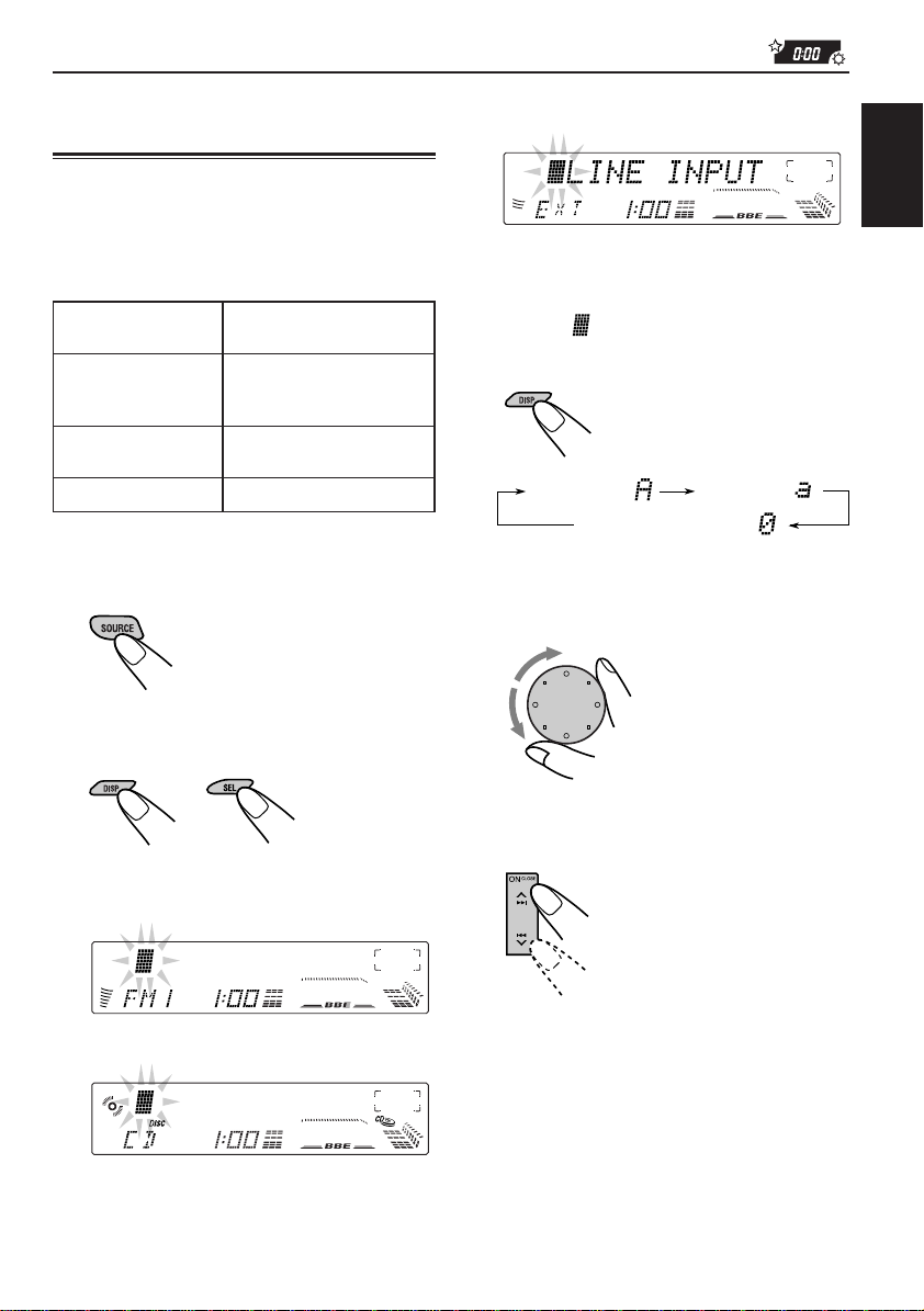
Assigning names to the
sources
When you select the external component
connected to LINE IN as the source:
You can assign names to station frequencies,
CDs and the external component connected to
the LINE IN plugs. After assigning a name, it will
appear on the display when you select the
source.
Sources Maximum number of the
Station frequencies Up to 12 characters (up to
CDs * and Up to 32 characters (up to
CD changer * 40 discs)
External component Up to 12 characters
* You cannot assign a name to a CD Text.
1
Select a source you want to assign a
name to.
2
Press and hold SEL (select) for more
than 2 seconds while pressing DISP.
characters
30 station frequencies
including both FM and AM)
3
Select the character set you want
while “
Each time you press the button, the
character set changes as follows:
4
Select a character.
About the available characters, see page
24.
5
Move the cursor to the next (or
previous) character position.
” is flashing.
Capital letter ( )
Numbers and symbols ( )
Small letter ( )
ENGLISH
When you select a station frequency as the
source:
When you select the CD as the source:
CONTINUED ON NEXT PAGE
23
Page 24

6
Repeat steps 3 to 5 until you finish
inputting the name.
7
Press the button while the last
ENGLISH
selected character is flashing.
The input name is stored in memory.
Available characters
Capital letters
A B C D E F G H I J
K L M N O P Q R S T
U V W X Y Z
Small letters
space
To erase the input characters
Insert spaces using the same procedure
described above.
a b c d e f g h i j
k l m n o p q r s t
u v w x y z
Numbers and symbols
space
0 1 2 3 4 5 6 7 8 9
! ” # $ % & ’ ( )
+ , – . / : ; < =
? @ _ `
Notes:
• When you try to assign a name to the 41st disc,
“NAME FULL” appears on the display. (In this
case, delete unwanted names before assignment.)
• When the CD changer is connected, you can assign
names to CDs in the CD changer. These names can
also be shown on the display if you insert the CDs
in this unit.
space
*
>
24
Page 25

CD CHANGER OPERATIONS
SEL
78
MODE
DISP
SSM
We recommend that you use one of the CH-X series
with your unit.
If you have another CD automatic changer , consult
your JVC IN-CAR ENTERTAINMENT dealer for
connections.
• For example, if your CD automatic changer is one of
the KD-MK series, you need a cord (KS-U15K) for
connecting it to this unit.
Before operating your CD automatic changer:
• Refer also to the Instructions supplied with your
CD changer.
• If no discs are in the magazine of the CD
changer or the discs are inserted upside down,
“NO DISC” will appear on the display. If this
happens, remove the magazine and set the
discs correctly.
• If “RESET 1” - “RESET 8” appears on the
display, something is wrong with the
connection between this unit and the CD
changer. If this happens, check the connection,
connect the connecting cord(s) firmly if
necessary, then press the reset button of the
CD changer.
INT RPT RNDLOCALMONOSCM
9
10
11 12
KD-LX300
SOURCE
OFF
BAND
BBE
Playing CDs
Select the CD automatic changer.
Each time you press the button,
the source changes as described
on page 7.
Playback starts from the first track
of the first disc.
All tracks of all discs are played
back.
Track number
Disc number appears.
To fast-forward or reverse the track
Press and hold ¢, while pla ying
a CD, to fast-forward the track.
Press and hold 4 , while pla ying
a CD, to reverse the track.
Elapsed playing time
ENGLISH
To go to the next track or the previous tracks
Press ¢ briefly, while playing
a CD, to go ahead to the beginning
of the next track. Each time you
press the button consecutively , the
beginning of the next track is
located and played back.
Press 4 briefly , while pla ying
a CD, to go back to the beginning
of the current track. Each time you
press the button consecutively , the
beginning of the previous tracks is
located and played back.
25
Page 26

To go to a particular disc directly
Press the number button corresponding to the disc
number to start its playback (while the CD changer
is playing).
ENGLISH
• To select a disc number from 1 – 6:
Press 1 (7) – 6 (12) briefly.
• To select a disc number from 7 – 12:
Press and hold 1 (7) – 6 (12) for more than 1
second.
Track number
Elapsed playing time
Selecting CD playback modes
• There is a time limit in doing the following
procedure. If the setting is cancelled before you
finish, start from step 1 again.
To play back tracks at random (Random
Play)
1 Press MODE while playing a CD.
“MODE” appears on the display.
Disc number
Ex.: When disc number 3 is selected
To show the CD Text information
This is possible only when connecting a JVC CD
automatic changer equipped with CD Text
reading capability.
See “Playing a CD Text” on page 13.
2 Press RND (random), while “MODE” is still on
the display, so that the RND indicator lights up
on the display.
Each time you press the button, CD random play
mode changes as follows:
RANDOM1 RANDOM2
Canceled
Mode
RANDOM1 Lights All tracks of the current
RANDOM2 Flashes All tracks of all discs
RND
Indicator
Plays at random
disc, then the tracks of
the next disc, and so on.
inserted in the
magazine.
26
Page 27

To play back tracks repeatedly (Repeat Play)
1 Press MODE while playing a CD.
“MODE” appears on the display.
To play back only intros (Intro Scan)
1 Press MODE while playing a CD.
“MODE” appears on the display.
ENGLISH
2 Press RPT (repeat), while “MODE” is still on the
display , so that the RPT indicator lights up on the
display .
Each time you press the button, CD repeat play
mode changes as follows:
REPEAT1 REPEAT2
Canceled
Mode
REPEAT1 Lights The current track (or
REPEAT2 Flashes All tracks of the current
RPT
Indicator
Plays
repeatedly
specified track).
disc (or specified disc).
2 Press INT (intro), while “MODE” is still on the
display.
Each time you press the button, CD intro scan
mode changes as follows:
INTRO1 INTRO2
Canceled
Plays the
Mode
INTRO1
INTRO2
Indication
Track number
flashes
Disc number
flashes (when it
is shown on the
display)
beginnings
(15 seconds)
Of all tracks on all
inserted discs.
Of the first track on
each inserted disc.
27
Page 28

EXTERNAL COMPONENT OPERATIONS
SEL
MODE
DISP
ENGLISH
SSM
Playing an external component
When connecting an external component to the
LINE IN plugs on the rear, you can select the
component as the sound source.
1
Select the external component.
Each time you press the
button, the source changes
as described on page 7.
2
Operate the external component.
Note:
For the external component connection, see the
Installation/Connection Manual (separate volume).
78
INT RPT RNDLOCALMONOSCM
9
10
11 12
KD-LX300
SOURCE
OFF
BAND
BBE
Using a subwoofer
By connecting a subwoofer to the SUBWOOFER
OUT plugs on the rear, you can enjoy enhanced
bass sounds and a more realistic theater
atmosphere in your car.
• Refer also to the instructions supplied with your
subwoofer.
When a subwoofer is connected to this unit, select
an appropriate cutoff frequency level for your
subwoofer.
To set the subwoofer cutoff frequency, see “To
select the subwoofer cutoff frequency — W OOFER
FREQ” on page 20.
To adjust the subwoofer output volume, see
“Adjusting the sound” on page 14.
28
Page 29

TROUBLESHOOTING
What appears to be trouble is not always serious. Check the following points before calling a service
centre.
Symptoms
• CD cannot be played back.
• CD sound is sometimes
interrupted.
• Sound cannot be heard from
the speakers.
• SSM (Strong-station
Sequential Memory)
automatic preset does not
work.
• Static noise while listening to
the radio.
• “NO DISC” appears on the
display.
• “RESET 8” appears on the
display.
Causes
CD is inserted upside down.
You are driving on rough roads.
CD is scratched.
Connections are incorrect.
The volume level is set to the
minimum level.
Connections are incorrect.
Signals are too weak.
The antenna is not connected
firmly.
No CD is in the magazine.
This unit is not connected to a
CD changer correctly.
Remedies
Insert the CD correctly.
Stop CD play while driving on
rough roads.
Change the CD.
Check the cords and
connections.
Adjust it to the optimum level.
Check the cords and
connections.
Store stations manually.
Connect the antenna firmly.
Insert CD.
Connect this unit and the CD
changer correctly and press the
reset button of the CD changer.
ENGLISH
• “RESET 1” - “RESET 7”
appears on the display.
• “EJECT ERROR” appears on
the display and CD cannot be
ejected.
• No message appears on the
display but CD cannot be
ejected.
• This unit does not work at all.
• The CD changer does not
work at all.
The CD player may function
incorrectly.
The built-in microcomputer may
function incorrectly due to noise,
etc.
Press the reset button of the
CD changer.
Press and hold 4 for
more than 5 seconds.
While holding ¢, press the
reset button. Release the reset
button, then release ¢.
(Be careful not to drop the CD
when ejecting.)
Press the reset button on the
front panel. (See page 2.)
29
Page 30

MAINTENANCE
Handling CDs
This unit has been designed to reproduce the
CDs bearing the following marks.
ENGLISH
COMPACT
DIGITAL AUDIO
You can play back your original CD-Rs
(Recordable) and CD-RWs (Rewritable) on this
receiver.
This unit is not compatible with MP3.
How to handle CDs
When removing a CD from
its case, press down the center
holder of the case and lift the
CD out, holding it by the edges.
• Always hold the CD by the edges. Do not touch
its recording surface.
When storing a CD into its case, gently insert
the CD around the center holder
(with the printed surface facing up).
• Make sure to store CDs into the cases after
use.
Center holder
To keep CDs clean
A dirty CD may not play
correctly. If a CD does
become dirty, wipe it with a
soft cloth in a straight line
from center to edge.
To play new CDs
New CDs may have some
rough spots around the inner
and outer edges. If such a CD
is used, this unit may reject
the CD.
To remove these rough spots, rub the edges with
a pencil or ball-point pen, etc.
About mistracking:
Mistracking may result from driving on extremely
rough roads. This does not damage the unit and
the CD, but will be annoying.
We recommend that you stop CD play while
driving on such rough roads.
Moisture condensation
Moisture may condense on the lens inside the
CD player in the following cases:
• After starting the heater in the car.
• If it becomes very humid inside the car.
Should this occur, the CD player may
malfunction. In this case, eject the CD and leave
the unit turned on for a few hours until the
moisture evaporates.
When playing a CD-R or CD-RW
User-edited CD-Rs (Recordable) and CD-RWs
(Rewritable) can be played back only if they are
already “finalized. ”
• You can play back your original CD-Rs or CDRWs recorded in music CD format. (However,
they may not be played back depending on
their characteristics or recording conditions.)
• Before playing back CD-Rs or CD-RWs, read
their instructions or cautions carefully.
• Some CD-Rs or CD-RWs may not be played
back on this unit because of their disc
characteristics, damage or stain on them, or if
the player’s lens is dirty.
• CD-Rs or CD-RWs are susceptible to high
temperatures or high humidity; so do not leave
them inside your car.
• CD-RWs may require a longer readout time.
(This is caused by the fact that the reflectance
of CD-RWs is lower than for regular CDs.)
CAUTIONS:
• Do not insert 8cm (3 3/16") CDs (single CDs)
into the loading slot. (Such CDs cannot be
ejected.)
• Do not insert any CD of unusual shape – like a
heart or flower; otherwise, it will cause a
malfunction.
• Do not expose CDs to direct sunlight or any heat
source or place them in a place subject to high
temperature and humidity. Do not leave them in a
car.
• Do not use any solvent (for example,
conventional record cleaner, spray, thinner,
benzine, etc.) to clean CDs.
30
Page 31

SPECIFICATIONS
AUDIO AMPLIFIER SECTION
Maximum Power Output:
Front: 50 W per channel
Rear: 50 W per channel
Continuous Power Output (RMS):
Front: 19 W per channel into 4 Ω, 40 Hz
to 20 000 Hz at no more than
0.8% total harmonic distortion.
Rear: 19 W per channel into 4 Ω, 40 Hz
to 20 000 Hz at no more than
0.8% total harmonic distortion.
Load Impedance: 4 Ω (4 Ω to 8 Ω allowance)
Tone Control Range:
Bass: ±10 dB at 100 Hz
Treble: ±10 dB at 10 kHz
Frequency Response: 40 Hz to 20 000 Hz
Signal-to-Noise Ratio: 70 dB
Line-In Level/Impedance:
1.5 V/20 kΩ load
Line-Out Level/Impedance:
4.0 V/20 kΩ load (full scale)
Output Impedance: 1 kΩ
TUNER SECTION
Frequency Range:
FM: 87.5 MHz to 107.9 MHz
(with channel interval set to 200 kHz)
87.5 MHz to 108.0 MHz
(with channel interval set to 50 kHz)
AM: 530 kHz to 1 710 kHz
(with channel interval set to 10 kHz)
531 kHz to 1 602 kHz
(with channel interval set to 9 kHz)
[FM Tuner]
Usable Sensitivity: 11.3 dBf (1.0 µV/75 Ω)
50 dB Quieting Sensitivity:
16.3 dBf (1.8 µV/75 Ω)
Alternate Channel Selectivity (400 kHz):
65 dB
Frequency Response: 40 Hz to 15 000 Hz
Stereo Separation: 35 dB
Capture Ratio: 1.5 dB
CD PLAYER SECTION
Type: Compact disc player
Signal Detection System: Non-contact optical
pickup (semiconductor laser)
Number of channels: 2 channels (stereo)
Frequency Response: 5 Hz to 20 000 Hz
Dynamic Range: 96 dB
Signal-to-Noise Ratio: 98 dB
Wow and Flutter: Less than measurable limit
GENERAL
Power Requirement:
Operating Voltage: DC 14.4 V
(11 V to 16 V allowance)
Grounding System: Negative ground
Allowable Operating Temperature:
0°C to +40°C (32°F to 104°F)
Dimensions (W × H × D):
Installation Size:
182 mm × 52 mm × 160 mm
(7-3/16" × 2-1/16" × 6-5/16")
Panel Size:
188 mm × 58 mm × 8 mm
(7-7/16" × 2-5/16" × 3/8")
Mass: 1.8 kg (4.0 lbs)
(excluding accessories)
Design and specifications subject to change without
notice.
If a kit is necessary for your car, consult your
telephone directory for the nearest car audio
speciality shop.
ENGLISH
[AM Tuner]
Sensitivity: 20 µV
Selectivity: 35 dB
31
Page 32

http://www.jvcmobile.c
Visit us on-line for
Technical Support & Customer Satisfaction Survey.
US RESIDENTS ONLY
om
Having TROUBLE with operation?
Please reset your unit
Refer to page of How to Reset
Still having trouble??
USA ONLY
Call 1-800-252-5722
http://www.jvcservice.com
We can help you!
EN, SP, FR
VICTOR COMPANY OF JAPAN, LIMITED
1200MNMMDWTKR
JVC
Page 33

CAUTION / ACHTUNG / ATTENTION / LET OP
DEUTSCH
Um dieses Gerät zu installieren, bringen Sie zunächst den
Zierrahmen am Gerät an. Schieben Sie anschließend das Gerät in
die Schutzhülle, indem Sie auf die vier Ecken des Zierrahmens
drücken.
Drücken Sie NICHT auf die Blende (die in der Abbildung
dunkelgetönt dargestellt ist); anderenfalls läßt sich die Blende
weder öffnen noch schließen.
FRANÇAIS
Pour installer cet appareil, fixezd’abord la plaque d’assemblage à
l’appareil, puis ajustezl’appareil dans le manchon en appuyant sur
les quatre coins de la plaqued’assemblage. N’APPUYEZ PAS sur
le panneau (partie ombrée surl’illustration); sinon le panneau risque de ne pas pouvoir s’ouvrirou se fermer.
ENGLISH
To install this unit, attach the trim plate to the unit first, then fit the
unit into the mounting sleeve by pressing the four corners of the
trim plate.
DO NOT press the panel (shaded in the illustration); otherwise the
panel may become unable to open or close.
NEDERLANDS
Om dit apparaat te installeren, dient u eerst de sierplaat op het
apparaat te bevestigen, daarna het apparaat in de behuizing te
plaatsen en de vier hoeken van de sierplaat aan te drukken.
Druk NIET op het paneel (gearceerd in de illustratie aangegeven),
anders loopt u het risico dat het paneel niet meer kan worden
geopend of gesloten.
Page 34

IMPORTANT
Notice the following information will help you solve the problems.
Keep this IMPORTANT sheet together with the INSTRUCTIONS book.
• After installing the unit
= Follow the procedure Å described below.
• If the unit does not operate
= Follow the procedure Å described below.
• If a CD is not ejected from the loading slot
1 “EJECT ERR” or “EJECT ERROR” appears on the display
= Follow the procedure ı described below. (If the procedure ı does not work, try
the procedure Å.)
2 No message appears on the display
= Follow the procedure Ç described below.
• If a CD is not recognized (the source does not change to the
CD) even though there is a CD in the loading slot
= Follow the procedure Ç described below. (If the procedure Ç does not work, try
the procedure Å.)
Å To reset the microcomputer
Press the reset button on the front panel using a ball-point pen or a similar tool.
This will reset the built-in microcomputer.
NOTE: Your preset adjustments — such as preset channels or sound adjustments
— will also be erased.
Reset button
ı To eject a CD by force
Press and hold
4
button until CD ejects.
4
button
Ç To eject a CD by force
While holding ¢, press the reset button. Release the reset button, then release
¢. (Be careful not to drop the CD when ejecting.)
Reset button
¢ button
Page 35

KD-LX300
KD-LX100
Installation/Connection Manual
Manual de instalación/conexión
Manuel d’installation/raccordement
PIM163700
[J]
1200MNMMDWTKR
JVC
EN, SP, FR
ENGLISH
• This unit is designed to operate on 12 V DC, NEGATIVE ground
electrical systems.
INSTALLATION
(IN-DASH MOUNTING)
• The following illustration shows a typical installation. However,
you should make adjustments corresponding to your specific car .
If you have any questions or require information regarding
installation kits, consult your JVC car audio dealer or a company
supplying kits.
1
Remove the trim plate.
2
Remove the sleeve after disengaging the sleeve locks.
1 Stand the unit.
Note: When you stand the unit, be careful not to damage
the fuse on the rear.
2 Insert the 2 handles between the unit and the sleeve, as
illustrated, to disengage the sleeve locks.
3 Remove the sleeve.
Note: Be sure to keep the handles for future use after
installing the unit.
3
Attach the trim plate.
4
Install the sleeve into the dashboard.
* After the sleeve is correctly installed into the dashboard, bend
the appropriate tabs to hold the sleeve firmly in place, as
illustrated.
5
Fix the mounting bolt to the rear of the unit’s body and place
the rubber cushion over the end of the bolt.
6
Do the required electrical connections.
7
Slide the unit into the sleeve until it is locked by pressing the
four corners of the trim plate.
Note: Do not press the panel (shaded in the illustration);
otherwise the panel may become unable to open or close.
ESPAÑOL
• Esta unidad está diseñada para funcionar con 12 V de CC, con
sistemas eléctricos de masa NEGATIVA.
INSTALACION (MONTAJE EN EL
TABLERO DE INSTRUMENTOS)
• La siguiente ilustración muestra una instalación típica. Sin
embargo usted deberá efectuar los ajustes correspondientes a
su automóvil. Si tiene alguna pregunta o necesita información
acerca de las herramientas para instalación, consulte con su
concesionario de JVC de equipos de audio para automóviles o
a una compañía que suministra tales herramientas.
1
Retire la placa de guarnición.
2
Retire la cubierta después de desenganchar los retenes de la
cubierta.
1 Ponga la unidad vertical.
Nota: Al poner la unidad vertical, tenga cuidado de no
dañar el fusible provisto en la parte posterior.
2 Inserte las dos manijas entre la unidad y la cubierta tal
como en la ilustración y desenganche los retenes de la
cubierta.
3 Retire la cubierta.
Nota: Después de instalar la unidad, asegúrese de guardar
las manijas para uso futuro.
3
Instale la placa de guarnición.
4
Instale la cubierta en el tablero de instrumentos.
* Después de que la cubierta esté correctamente instalada
en el tablero de instrumentos, doble las lengüetas
correspondientes para sostener la cubierta firmemente en
su lugar, tal como se muestra.
5
Fije el perno de montaje en la parte trasera del cuerpo de la
unidad y coloque el cojín de goma sobre el extremo del perno.
6
Realice las conexiones eléctricas requeridas .
7
Deslice la unidad dentro de la cubierta hasta que quede
bloqueada al presionar contra las cuatro esquinas de la placa
de guarnición.
Nota: No presione el panel (sombreado en la ilustración); de
lo contrario, podría suceder que no se pueda realizar su
apertura o cierre.
FRANÇAIS
•
Cet appareil est conçu pour fonctionner sur des sources de
courant continu de 12 V à masse NEGATIVE.
INSTALLATION
(MONTAGE DANS LE TABLEAU DE BORD)
•
L’illustration suivante est un exemple d’installation typique.
Cependant, vous devez faire les ajustements correspondant à
votre voiture particulière. Si vous avez des questions ou avez
besoin d’information sur des kits d’installation, consulter votre
revendeur d’autoradios JVC ou une compagnie
d’approvisionnement.
1
Retirer la plaque d’assemblage.
2
Libérer les verrous du manchon et retirer le manchon.
1
Poser l’appareil à la verticale.
Remarque:
faire attention de ne pas endommager le fusible situé sur
l’arrière.
2
Insérer les 2 poignées entre l’appareil et le manchon comme
indiqué pour désengagé les verrous de manchon.
3
Retirer le manchon.
Remarque:
utilisation ultérieur, après l’installation de l’appareil.
3
Fixez la plaque d’assemblage.
4
Installer le manchon dans le tableau de bord.
* Après installation correcte du manchon dans le tableau de
bord, plier les bonnes pattes pour maintenir fermement le
manchon en place, comme montré.
5
Monter le boulon de montage sur l’arrière du corps de l’appareil
puis passer l’amortisseur en caoutchouc sur l’extrémité du
boulon.
6
Réalisez les connexions électriques.
7
Faites glisser l’appareil dans le manchon jusqu’à ce qu’il soit
verrouillé en appuyant sur les quatre coins de la plaque
d’assemblage.
Remarque:
l’illustration); sinon le panneau risquerait de ne pas pouvoir
s’ouvrir ou se fermer.
Lorsque vous mettez l’appareil à la verticale,
S’assurer de garder les poignées pour une
N’appuyez pas sur le panneau (ombré sur
1
Trim plate
Placa de guarnición
Plaque d’assemblage
3
2
Slot
Ranura
Fente
Handle
Manija
Poignée
Fuse
Fusible
Fusible
Lock Plate
Placa de bloqueo
Plaque de verrouillage
Rubber cushion
Cojín de goma
Amortisseur en caoutchouc
Sleeve
Cubierta
Manchon
4
Tablero de instrumentos
Dashboard
Tableau de bord
184 mm
(7-1/4")
53 mm
(2-1/8")
5
Sleeve
Cubierta
Manchon
7
4
Mounting bolt
Perno de montaje
Boulon de montage
See “ELECTRICAL CONNECTIONS.”
6
*
Véase “CONEXIONES ELECTRICAS”.
Référez-vous “RACCORDEMENTS
ELECTRIQUES”.
Page 36

• When using the optional stay
• Cuando emplea un soporte opcional
• Lors de l’utilisation du hauban en option
Tabique a prueba de incendios
Washer
Tablero de instrumentos
Dashboard
Tableau de bord
Arandela
Rondelle
Sleeve
Cubierta
Manchon
Fire wall
Cloison
Mounting bolt
Perno de montaje
Boulon de montage
Stay (option)
Soporte (opción)
Hauban (en option)
Lock nut
Tuerca de seguridad
Ecrou d’arrêt
Screw (option)
Tornillo (opción)
Vis (en option)
• When installing the unit without using the sleeve
• Instalación de la unidad sin utilizar la cubierta
• Lors de l’installation de l’appareil sans utiliser de manchon
In a Toyota for example, first remove the car radio and install the unit in its place.
En un Toyota por ejemplo, primero extraiga la radio del automóvil y luego instale la unidad en su
lugar.
Par exemple dans une Toyota, retirer d’abord l’autoradio et installer l’appareil à la place.
Flat type screws (M5 x 6 mm)*
Tornillos tipo plano (M5 x 6 mm)*
Vis à tête plate (M5 x 6 mm)*
Bracket*
Ménsula*
Support*
Pocket
Compartimiento
Poche
Note: When installing the unit on the mounting brac k et, mak e sure to use the 6 mm-long screws. If
longer screws are used, they could damage the unit.
Nota: Cuando instala la unidad en la ménsula de montaje, asegúrese de utilizar los tornillos de
6 mm de longitud. Si se utilizan tornillos más largos, éstos pueden dañar la unidad.
Remarque:
Lors de l’installation de l’appareil sur le support de montage, s’assurer d’utiliser des vis
d’une longueur de 6 mm. Si des vis plus longues sont utilisées , elles peuvent endommager l’appareil.
* Not included with this unit.
* No suministrado con esta unidad.
*
Non fourni avec cet appareil.
Flat type screws (M5 x 6 mm)*
Tornillos tipo plano (M5 x 6 mm)*
Bracket*
Ménsula*
Support*
Vis à tête plate (M5 x 6 mm)*
Removing the unit
• Before removing the unit, release the rear section.
1
Remove the trim plate.
2
Insert the 2 handles into the slots, as shown. Then, while gently
pulling the handles away from each other, slide out the unit.
(Be sure to keep the handles after installing it.)
Trim plate
Placa de guarnición
Plaque d’assemblage
Parts list for installation and connection
The following parts are provided with this unit.
After checking them, please set them correctly.
Sleeve
Cubierta
Manchon
Extracción de la unidad
• Antes de extraer la unidad, libere la sección trasera.
1
Retire la placa de guarnición.
2
Inserte las 2 manijas entre las ranuras, como se muestra.
Luego, separe gentilmente las manijas y extraiga la unidad.
(Asegúrese de conservar las manijas después de
instalarlo.)
21
Lista de piezas para instalación y conexión
Con esta unidad se suministran las siguientes piezas.
Después de inspeccionarlas, colóquelas correctamente.
Trim plate
Placa de guarnición
Plaque d’assemblage
Retrait de l’appareil
• Avant de retirer l’appareil, libérer la section arrière.
1
2
Handle
Manija
Poignée
Liste des pièces pour l’installation et
raccordement
Les pièces suivantes sont fournies avec cet appareil.
Après vérification, veuillez les placer correctement.
Remote controller
Control remoto
Télécommande
Retirer la plaque d’assemblage.
Introduire les deux poignées dans les fentes, comme montré.
Puis, tout en tirant doucement les poignées écartées, faire
glisser l’appareil pour le sortir.
(S’assurer de conserver les
poignées après l’installation de l’appareil.)
Battery
Pila
Pile
CR2025
Power cord
Cordón de alimentación
Cordon d’alimentation
Handles
Manijas
Poignées
ELECTRICAL CONNECTIONS
To prevent short circuits, we recommend that you disconnect the
battery’s negative terminal and make all electrical connections
before installing the unit. If you are not sure how to install this unit
correctly, have it installed by a qualified technician.
Note:
This unit is designed to operate on 12 V DC, NEGATIVE ground
electrical systems. If your vehicle does not have this system, a
voltage inverter is required, which can be purchased at JVC car
audio dealers.
• Replace the fuse with one of the specified rating. If the fuse blows
frequently, consult your JVC car audio dealer.
• If noise is a problem...
This unit incorporates a noise filter in the power circuit. Ho we v er ,
with some vehicles, clicking or other unw anted noise may occur.
If this happens, connect the unit’s rear ground terminal (See
connection diagram.) to the car’ s chassis using shorter and thicker
cords, such as copper braiding or gauge wire. If noise still persists,
consult your JVC car audio dealer.
• Maximum input of the speakers:
For KD-LX300: Maximum input of the speakers should be more
than 50 W at the rear and 50 W at the front, with an impedance
of 4 Ω to 8 Ω.
For KD-LX100: Maximum input of the speakers should be more
than 45 W at the rear and 45 W at the front, with an impedance
of 4 Ω to 8 Ω.
• Be sure to ground this unit to the car’s chassis.
• The heat sink becomes very hot after use. Be careful not to touch
it when removing this unit.
Sumidero térmico
Dissipateur de chaleur
Heat sink
Washer (ø5)
Arandela (ø5)
Rondelle (ø5)
Lock nut (M5)
Tuerca de seguridad (M5)
Ecrou d’arrêt (M5)
Mounting bolt (M5 x 20 mm)
Perno de montaje (M5 x 20 mm)
Boulon de montage (M5 x 20 mm)
CONEXIONES ELECTRICAS
Para evitar cortocircuitos, recomendamos que desconecte el
terminal negativo de la batería y que efectúe todas las conexiones
eléctricas antes de instalar la unidad. Si usted no está seguro de
cómo instalar correctamente la unidad, hágala instalar por un
técnico cualificado.
Nota:
Esta unidad está diseñada para funcionar con 12 V de CC, con
sistemas eléctricos de masa NEGA TIV A. Si su vehículo no posee
este sistema, será necesario un inversor de tensión, que puede
ser adquirido en los concesionarios de JVC de equipos de audio
para automóviles.
• Reemplace el fusible por uno con la corriente especificada. Si
el fusible se quemase frecuentemente consulte con su
concesionario de JVC de equipos de audio para automóviles.
• Si el ruido fuese un problema...
Esta unidad tiene un filtro de ruido en el circuito de alimentación.
Sin embargo, en algunos vehículos, pueden producirse
chasquidos u otros ruidos indeseados. En tal caso conecte el
terminal de tierra posterior (Véase diagrama de conexión.) del
receptor al chasis del automóvil, utilizando cordones más
gruesos y cortos tales como alambre de cobre trenzado o de
grueso calibre. Si el ruido persiste, consulte a su concesionario
de JVC de equipos de audio para automóvil.
• La entrada máxima de los altavoces:
Para KD-LX300: La entrada máxima de los altavoces traseros
debe ser mayor de 50 W y la de los delanteros de 50 W, con una
impedancia de 4 Ω a 8 Ω.
Para KD-LX100: La entrada máxima de los altavoces traseros
debe ser mayor de 45 W y la de los delanteros de 45 W, con una
impedancia de 4 Ω a 8 Ω.
• Asegúrese de conectar esta unidad a tierra en el chasis del
automóvil.
• El sumidero térmico estará muy caliente después del uso.
Asegúrese de no tocarlo al desmontar esta unidad.
Rubber cushion
Cojín de goma
Amortisseur en caoutchouc
RACCORDEMENTS ELECTRIQUES
Pour éviter tout court-circuit, nous vous recommandons de
débrancher la borne négative de la batterie et d’effectuer tous les
raccordements électriques avant d’installer l’appareil. Si l’on n’est
pas sûr de pouvoir installer correctement cet appareil, le faire
installer par un technicien qualifié.
Remarque:
Cet appareil est conçu pour fonctionner sur des sources de courant
continu de
ce type d’alimentation, il vous faut un conver tisseur de tension,
que vous pouvez acheter chez un revendeur d’autoradios JVC.
•
Remplacer le fusible par un de la valeur précisée. Si le fusible
saute souvent, consulter votre revendeur d’autoradios JVC.
•
Si le bruit est un problème...
Cet appareil incorpore un filtre de bruit dans le circuit
d’alimentation. Cependant, avec certains véhicules, quelques
claquements ou autres bruits non désirés risquent de se produire.
Si cela arrive, raccorder la
au châssis de la voiture (voir le schéma de raccordement) en
utilisant des cordons les plus gros et les plus courts possibles
telle qu’une barre de cuivre ou une tresse. Si le bruit persiste,
consulter votre revendeur d’autoradios JVC.
•
La puissance admissible des enceintes:
Pour le KD-LX300: La puissance admissible des enceintes doit
être supérieure à 50 W à l’arrière et à 50 W l’avant, avec une
impédance de
Pour le KD-LX100: La puissance admissible des enceintes doit
être supérieure à 45 W à l’arrière et à 45 W l’avant, avec une
impédance de
• S’assurer de raccorder la mise à la masse de cet appareil au
châssis de la voiture.
•
Le dissipateur de chaleur devient très chaud après usage. Faire
attention de ne pas le toucher en retirant cet appareil.
12 V à masse NEGATIVE
borne arrière de masse
4 Ω à 8 Ω
4 Ω à 8 Ω
.
.
. Si v otre véhicule n’offre pas
de l’appareil
Page 37

ENGLISH FRANÇAISESPAÑOL
PRECAUTIONS on power supply and speaker
connections:
• DO NOT connect the speaker leads of the power cord to the
car battery; otherwise, the unit will be seriously damaged.
• Connect the black lead (ground), yellow lead (to car battery,
constant 12 V), and red lead (to an accessory terminal) correctly .
• BEFORE connecting the speaker leads of the power cord to the
speakers, check the speaker wiring in your car.
– If the speaker wiring in your car is as illustrated in Fig. 1
and Fig. 2 below, DO NO T connect the unit using that original
speaker wiring. If you do, the unit will be seriously damaged.
Redo the speaker wiring so that you can connect the unit to
the speakers as illustrated in Fig. 3.
– If the speaker wiring in your car is as illustrated in Fig. 3,
you can connect the unit using the original speaker wiring in
your car .
– If you are not sure of the speaker wiring of your car, consult
your car dealer.
+
L
-
+
R
-
Fig. 1
+
-
+
-
+
L
-
+
R
-
Fig. 2
+
-
+
-
Fig. 3
PRECAUCIONES sobre las conexiones de la
fuente de alimentación y de los altavoces:
• NO conecte los conductores de altavoz del cable de
alimentación a la batería de automóvil, pues podrían
producirse graves daños en la unidad.
• Conecte correctamente el conductor negro (a tierra), el
conductor amarillo (a la batería del automóvil, 12 V constantes),
y el conductor rojo (a un terminal de accesorio).
• ANTES de conectar a los altavoces los conductores de altavoz
del cable de alimentación, verifique el conexionado de altavoz
de su automóvil.
– Si el conexionado de altavoz de su automóvil es como se
indica en las Fig. 1 y Fig. 2 de abajo, NO conecte la unidad
utilizando ese conexionado de altavoz original. Si lo hace, se
producirán daños graves en la unidad.
Vuelva a efectuar el conexionado de altavoz de manera que
pueda conectar la unidad a los altavoces de la manera
indicada en la Fig. 3.
– Si el conexionado de altavoz de su automóvil es como se
indica en la Fig. 3, podrá conectar la unidad utilizando el
conexionado de altavoz original de su automóvil.
– Si tiene dudas sobre el conexionado de altavoz de su
automóvil, consulte con su concesionario.
Connecting the leads / Conexión de los conductores / Raccordement des fils
Twist the core wires when connecting.
Retuerce los alambres de alma para
conectarlos.
Torsader les âmes des fils en les
raccordant.
Solder the core wires to connect them securely.
Suelde los alambres de alma para conectarlos con
firmeza.
Souder les âmes desfils pour les raccorder entre eux
de façon sûre.
PRECAUTIONS sur l’alimentation et la connexion
des enceintes:
• NE CONNECTEZ PAS les fils d’enceintes du cordon
d’alimentation à la batterie; sinon, l’appareil serait
sérieusement endommagé.
•
Connectez correctement le fil noir (a la masse), le fil jaune (a la
batterie de la voiture,12 V constant) et le fil rouge (à la prise
accessoire).
•
AVANT de connecter les fils des enceintes du cordon
d’alimentation aux enceintes, vérifiez le câblage des enceintes
de votre voiture.
–
Si le câblage des enceintes de votre voiture est réalisé
comme montré sur la Fig. 1 ou Fig. 2 ci-dessous,
CONNECTEZ PAS l’appareil en utilisant ce câblage original
d’enceintes. Si vous le faites, l’appareil sera sérieusement
endommagé.
Recommencez le câblage des enceintes de façon que vous
puissiez connecter l’appareil aux enceintes comme montré sur
la Fig. 3.
–
Si le câblage des enceintes de votre voiture est comme
montré sur la Fig. 3,
utilisant ce câblage original d’enceintes pour votre voiture.
– Si vous n’êtes pas sûrs du câblage d’enceintes de votre voiture,
consulter le concessionnaire de votre voiture.
CAUTION / PRECAUCION / PRECAUTION:
• To prevent short-circuit, cover the terminals of the UNUSED leads with
insulating tape.
• Para evitar cortocircuitos, cubra los cables NO UTILIZADOS con cinta
aislante.
• Pour éviter les court-circuits, couvrir les bornes des fils qui ne sont PAS
utilisés avec de la bande isolante.
vous pouvez connecter l’appareil en
NE
A Typical Connections / Conexiones tipicas / Raccordements typiques
Before connecting: Check the wiring in the vehicle carefully.
Incorrect connection may cause serious damage to this unit.
1
Connect the colored leads of the power cord to the car battery ,
speakers and power antenna (if any) in the f ollowing sequence.
1 Black: ground
2 Yellow: to car battery (constant 12 V)
3 Red: to an accessory terminal
4 Blue with white stripe: to power antenna (200 mA max.)
5 Orange with white stripe: to car light control switch
6 Others: to speakers
2
Connect the antenna cord.
3
Finally connect the wiring harness to the unit.
Antenna terminal
Terminal de la antena
Borne de l’antenne
To subwoofer (see diagram B )
Al subwoofer (véase diagrama B )
Au caisson de grave (voir le diagramme B )
To antenna
A la antena
A l’antenne
2
15
15 A fuse
Fusible de 15 A
Fusible 15 A
Antes de la conexión: Verifique atentamente el conexionado del
vehículo. Una conexión incorrecta podría producir daños graves
en la unidad.
1
Conecte los conductores de color del cable de alimentación a
la batería del automóvil, altavoces y antena motriz (si la hubiere)
en la secuencia siguiente.
1 Negro: a tierra
2 Amarillo: a la batería del automóvil (12 V constantes)
3 Rojo: a un terminal de accesorio
4 Azul con rayas blancas: a la antena motriz (máx. 200 mA)
5 Naranja con rayas blancas: al interruptor de control de
las luces del automóvil
6 Otros: a los altavoces
2
Conecte el cable de antena.
3
Por último, conecte el cable de alimentación a la unidad.
JVC CD changer jack
Jack para el cambiador de CD de JVC
Prise CD changeur JVC
3
Black
Negro
Noire
1
When connecting a CD changer, we recommend that you connect one of the CH-X series CD changers.
• If your CD changer is one of the KD-MK series, you need an optional cord (KS-U15K).
ONL Y FOR KD-LX100: You can also use an external component such as a portable MD player by connecting
the Line Input Adaptor KS-U57 (not supplied). (See diagram B )
Cuando conecte un cambiador de CD, se recomienda utilizar uno de la serie CH-X.
• Si su cambiador de CD es de la serie KD-MK, necesitará un cable opcional (KS-U15K).
SOLO PARA KD-LX100: Conectando el adaptador de entrada de línea KS-U57 (no suministrado), también
podrá usar un componente exterior, tal como un reproductor de MD. (Véase diagrama B )
Lors de la connexion d’un changeur CD, nous vous recommandons d’utiliser un des changeurs CD de la
série CH-X.
• Si votre changeur appartient à la série KD-MK, vous avez besoin d’un cordon optionnel (KS-U15K).
SEULEMENT POUR LE KD-LX100: Vous pouvez aussi utiliser un appareil extérieur tel qu’un lecteur de
MD en connectant l’adaptateur d’entrée de ligne KS-U57 (non fourni) (voir le diagramme B ).
To metallic body or chassis of the car
A un cuerpo metálico o chasis del automóvil
Vers corps métallique ou châssis du véhicule
Avant de commencer la connexion:
vérifiez attentivement le
câblage du véhicule. Une connexion incorrecte peut endommager
sérieusement l’appareil.
1
Connectez les fils de couleur du cordon d’alimentation à la
batterie de la voiture, aux enceintes et à l’antenne automatique
(s’il y en a une) dans l’ordre suivant.
1
Noir: à la masse
2
Jaune: à la batterie de la voiture (12 V constant)
3
Rouge: à la prise accessoire
4
Bleu avec bande blanche: à l’antenne automatique
(200 mA max.)
5
Orange avec bande blanche: à l’interrupteur d’éclairage
de la voiture
6
Autres: aux enceintes
2
Connectez le cordon d’antenne.
3
Finalement, connectez le faisceau de fils à l’appareil.
Ignition switch
*
Interruptor de encendido
Interrupteur d’allumage
*
Rear ground terminal
Terminal de tierra posterior
Borne arrière de masse
*1: Before checking the operation of this unit prior to
installation, this lead must be connected, otherwise
power cannot be turned on.
*1: Antes de comprobar el funcionamiento de esta unidad
previa a de la instalación, es necesario conectar este
cable, de lo contrario no se podrá conectar la
alimentación.
*1:Pour vérifier le fonctionnement de cet appareil avant
installation, ce fil doit être raccordé, sinon l’appareil
ne peut pas être mis sous tension.
White with black stripe
Blanco con rayas negras
Blanc avec bande noire
Line out/in (see diagram B )
Salida/entrada de línea
(véase diagrama B )
Sortie/entrée de ligne
(voir le diagramme B )
1
White
Blanco
Blanc
Left speaker (front)
Altavoz izquierdo (frontal)
Enceinte gauche (avant)
6
Gray with blac k stripe
Gris con rayas negras
Gris avec bande noire
1
Yellow*
Amarillo*
Jaune*
Red
Rojo
Rouge
1
1
To a live terminal in the fuse block connecting to the car battery
(bypassing the ignition switch)
A un terminal activo del bloque de fusibles conectado a la batería
del automóvil (desviando el interruptor de encendido)
2
A une borne sous tension du porte-fusible connectée à la batterie
de la voiture (en dérivant l’interrupteur d’allumage)
3
Blue with white stripe
Azul con rayas blancas
Bleu avec bande blanche
Orange with white stripe
Naranja con rayas blancas
Orange avec bande blanche
Gray
Gris
Gris
Right speaker (front)
Altavoz derecho (frontal)
Enceinte droit (avant)
To an accessory terminal in the fuse block
A un terminal accesorio del bloque de fusibles
Vers borne accessoire du porte-fusible
To power antenna if any
4
A la antena motriz, si la hubiere
Vers l’antenne automatique, s’il y en a une
(ILLUMINATION)
Green with black stripe
Verde con rayas negras
V ert avec bande noire
To car light control switch
5
Al interruptor de control de las luces del automóvil
À l’interrupteur d’éclairage de la voiture
Green
Verde
Vert
Left speaker (rear)
Altavoz izquierdo (trasero)
Enceinte gauche (arrière)
Purple with black stripe
Púrpura con rayas negras
Violet avec bande noire
Fuse block
Bloque de fusibles
Porte-fusible
Not included with this unit.
*
No suministrado con esta unidad.
Non fourni avec cet appareil.
Purple
Púrpura
Violet
Right speaker (rear)
Altavoz derecho (trasero)
Enceinte droit (arrière)
Page 38

B Connections Adding Other Equipment / Conexiones para añadir otros equipos / Raccordement pour ajouter d’autres appareils
You can connect an amplifier and other equipment to upgrade
your car stereo system. For their connections, refer to the
instructions supplied with each component.
• Connect the remote lead (blue with white stripe) to the remote
lead of the other equipment so that it can be controlled through
this unit.
• For amplifier only:
– Disconnect the speakers from this unit, connect them to
the amplifier. Leave the speaker leads of this unit unused.
– ONL Y FOR KD-LX300: The line output level of this unit is kept
high to maintain the hi-fi sounds reproduced from this unit.
When connecting an external amplifier to this unit, turn
down the gain control on the external amplifier to obtain the
best performance from this unit.
• ONLY FOR KD-LX300: Connect this unit’s SUBWOOFER OUT
plugs to the amplifier’s line-in jacks.
Usted podrá conectar un amplificador y otros equipos para
mejorar el sistema estéreo de su automóvil. Para las conexiones,
refiérase a las instrucciones suministradas con cada componente.
• Conecte el conductor remoto (azul con rayas blancas) al
conductor remoto del otro equipo para poderlo controlar a través
de esta unidad.
• Sólo para el amplificador:
– Desconecte los altavoces de esta unidad y conéctelos al
amplificador. Los cables de los altavoces de esta unidad
quedan sin usar.
– SOLO PARA KD-LX300: El nivel de salida de línea de esta
unidad permanece alto para que corresponda con los sonidos
de alta fidelidad reproducidos por esta unidad.
Cuando conecte un amplificador externo a esta unidad,
disminuya el control de ganancia del amplificador externo
para obtener un óptimo rendimiento de esta unidad.
• SOLO PARA KD-LX300: Conecte las clavijas SUBWOOFER OUT
de esta unidad a los jacks de entrada de línea del amplificador.
Vous pouvez connecter un amplificateur ou autre appareil pour
améliorer votre système autoradio. Pour leur connexion, référezvous aux instructions fournies avec chaque appareil.
• Connectez le fil de commande à distance (bleu avec bande
blanche) au fil de commande à distance de l’autre appareil de
façon qu’il puisse être commandé via cet appareil.
• Pour l’amplificateur seulement:
– Déconnectez les enceintes de cet appareil et connectez-
les à l’amplificateur. Laissez les fils d’enceintes de cet
appareil inutilisés.
– SEULEMENT POUR LE KD-LX300: Le niveau de sortie de ligne
de cet appareil est maintenu à un niveau élevé pour maintenir
une qualité Hi-Fi pour les sons reproduits par cet appareil.
Lors de la connexion d’un amplificateur extérieur à
cet appareil, diminuez le réglage du gain sur l’amplificateur
extérieur pour obtenir les meilleures performances de cet
appareil.
•
SEULEMENT POUR LE KD-LX300: Connectez les fiches
SUBWOOFER OUT de cet appareil aux prises d’entrée de ligne
de l’amplificateur.
Amplifier / Amplificador / Amplificateur
Rear speakers
Altavoces posteriores
Enceintes arrière
INPUT
L
R
Signal cord (not supplied with this unit)
Cable de señal (no suministrado con esta unidad)
Cordon de signal (non fourni avec cet appareil)
L
R
Altavoces delanteros
Signal cord (not supplied with this unit)
Cable de señal (no suministrado con esta unidad)
Cordon de signal (non fourni avec cet appareil)
L
R
LINE OUT
(REAR)
L
RR
Front speakers
Enceintes avant
JVC Amplifier
Amplificador de JVC
JVC Amplificateur
LINE OUT
(FRONT)
L
KD-LX300/
KD-LX100
Remote lead
Cable remoto
Fil d’alimentation à distance
Remote lead (Blue with white stripe)
Cable remoto (Azul con rayas blancas)
Fil d’alimentation à distance (Bleu avec bande blanche)
Y-connector (not supplied with this unit)
Conector en Y (no suministrado con esta unidad)
Connecteur Y (non fourni avec cet appareil)
CAUTION / PRECAUCIONES / PRECAUTION:
• To prevent internal heat buildup inside this unit, place this unit UNDER the other equipment.
• Para evitar el aumento del calor interior de esta unidad, póngala DEBAJO del otro equipo.
• Pour éviter un échauffement interne de cet appareil, placez-le SOUS l’autre appareil.
ONLY FOR KD-LX300:
You can connect another power
amplifier for front speakers.
L
R
SOLO PARA KD-LX300:
Podrá conectar otro amplificador de
potencia para los altavoces
delanteros.
INPUT
To power antenna if any
A la antena motriz, si la hubiere
Vers l’antenne automatique, s’il y en a une
SEULEMENT POUR LE KD-LX300:
Vous pouvez connecter un autre
amplificateur de puissance pour les
enceintes avant.
L
R
JVC Amplifier
Amplificador de JVC
JVC Amplificateur
Front speakers
Altavoces delanteros
Enceintes avant
External component / Componente exterior / Appareil extérieur
FOR KD-LX300/PARA KD-LX300/POUR LE KD-LX300
Signal cord (not supplied with this unit)
Cable de señal (no suministrado con esta unidad)
Cordon de signal (non fourni avec cet appareil)
KD-LX300
L
R
LINE IN
FOR KD-LX100/PARA KD-LX100/POUR LE KD-LX100
Line Input Adaptor KS-U57 (not supplied with this unit)
Adaptador de entrada de línea KS-U57 (no suministrado con esta unidad)
Adaptateur d’entrée de ligne KS-U57 (non fourni avec cet appareil)
KD-LX100
CD changer jack
Toma del cambiador de CD
Prise du changeur CD
Source equipment
Equipo fuente
Appareil source
Signal cord (not supplied with this unit)
Cable de señal (no suministrado con esta unidad)
Cordon de signal (non fourni avec cet appareil)
KD-LX300
SUBWOOFER OUT
L
R
Signal cord (not supplied with this unit)
Cable de señal (no suministrado con esta unidad)
Cordon de signal (non fourni avec cet appareil)
L
R
L
R
Amplifier
Amplificador
Amplificateur
L
R
External component
Componente exterior
Appareil extérieur
Subwoofer
Subwoofer
Caisson de grave
L
R
TROUBLESHOOTING
• The fuse blows.
* Are the red and black leads connected correctly?
• Power cannot be turned on.
* Is the yellow lead connected?
• No sound from the speakers.
* Is the speaker output lead short-circuited?
• Sound is distorted.
* Is the speaker output lead grounded?
* Are the “–” terminals of L and R speakers grounded in common?
• The unit becomes hot.
* Is the speaker output lead grounded?
* Are the “–” terminals of L and R speakers grounded in common?
LOCALIZACION DE AVERIAS
• El fusible se quema.
* ¿Están los conductores rojo y negro correctamente conectados?
• No es posible conectar la alimentación.
* ¿Está el cable amarillo conectado?
• No sale sonido de los altavoces.
* ¿Está el cable de salida del altavoz cortocircuitado?
• El sonido presenta distorsión.
* ¿Está el cable de salida del altavoz conectado a masa?
* ¿Están los terminales “–” de los altavoces L y R conectados a
una masa común?
• La unidad se calienta.
* ¿Está el cable de salida del altavoz conectado a masa?
* ¿Están los terminales “–” de los altavoces L y R conectados a
una masa común?
EN CAS DE DIFFICULTES
• Le fusible saute.
*
Les fils rouge et noir sont-ils racordés correctement?
• L’appareil ne peut pas être mise sous tension.
Le fil jaune est-elle raccordée?
*
• Pas de son des enceintes.
Le fil de sortie d’enceinte est-il court-circuité?
*
• Le son est déformé.
Le fil de sortie d’enceinte est-il à la masse?
*
*
Les bornes “–” des enceintes gauche et droit sont-elles mises
ensemble à la masse?
• L’appareil devient chaud.
*
Le fil de sortie d’enceinte est-il à la masse?
*
Les bornes “–” des enceintes gauche et droit sont-elles mises
ensemble à la masse?
Page 39

CD RECEIVER KD-LX100
ENGLISH
RECEPTOR CON CD KD-LX100
RECEPTEUR CD KD-LX100
78
MODE
SEL
DISP
SSM
10
INT RPT RNDLOCALMONOSCM
9
For installation and connections, refer to the separate manual.
Para la instalación y las conexiones, refiérase al manual separado.
Pour l’installation et les raccordements, se référer au manuel séparé.
11 12
KD-LX100
SOURCE
OFF
BAND
BBE
ESPAÑOL
FRANÇAIS
INSTRUCTIONS
MANUAL DE INSTRUCCIONES
MANUEL D’INSTRUCTIONS
For customer Use:
Enter below the Model No. and
Serial No. which are located on
the top or bottom of the cabinet.
Retain this information for future
reference.
Model No.
Serial No.
PIM163600
[J]
Page 40

INFORMATION (For U.S.A.)
This equipment has been tested and found to comply with the limits for a Class B digital device,
pursuant to Part 15 of the FCC Rules. These limits are designed to provide reasonable protection
against harmful interference in a residential installation. This equipment generates, uses, and can
radiate radio frequency energy and, if not installed and used in accordance with the instructions,
ENGLISH
may cause harmful interference to radio communications. However, there is no guarantee that
interference will not occur in a particular installation. If this equipment does cause harmful
interference to radio or television reception, which can be determined by turning the equipment off
and on, the user is encouraged to try to correct the interference by one or more of the following
measures:
– Reorient or relocate the receiving antenna.
– Increase the separation between the equipment and receiver.
– Connect the equipment into an outlet on a circuit different from that to which the receiver is
connected.
– Consult the dealer or an experienced radio/TV technician for help.
IMPORTANT FOR LASER PRODUCTS
Precautions:
1. CLASS 1 LASER PRODUCT
2. DANGER: Invisible laser radiation when open and interlock failed or defeated. Avoid direct
exposure to beam.
3. CAUTION: Do not open the top cover. There are no user-serviceable parts inside. Leave all
servicing to qualified service personnel.
4. CAUTION: This CD player uses invisible laser radiation, however, is equipped with safety switches
to prevent radiation emission when unloading CDs. It is dangerous to defeat the safety switches.
5. CAUTION: Use of controls, adjustments or performance of procedures other than those specified
herein may result in hazardous radiation exposure.
How to reset your unit
Press the reset button on the front panel using a ball-point pen or a similar tool.
This will reset the built-in microcomputer.
Note:
Your preset adjustments — such as preset channels or sound adjustments — will also be erased.
CAUTION on Volume Setting
CDs produce very little noise compared with other sources. If the volume level is adjusted for the
tuner , for example, the speak ers may be damaged by the sudden incr ease in the output level. Therefor e,
lower the volume before playing a disc and adjust it as required during playback.
2
Page 41

Thank you for purchasing a JVC product. Please read all instructions carefully before operation,
to ensure your complete understanding and to obtain the best possible performance from the unit.
CONTENTS
LOCATION OF THE BUTTONS............ 4
Control panel ........................................... 4
Remote controller .................................... 5
Preparing the remote controller ................ 6
BASIC OPERATIONS ...................... 7
RADIO BASIC OPERATIONS ............. 8
Listening to the radio ................................ 8
Storing stations in memory ....................... 9
Tuning into a preset station....................... 10
CD OPERATIONS .......................... 11
Playing a CD............................................ 11
Locating a track or a particular portion
on a CD ................................................. 12
Selecting CD playback modes.................. 12
Prohibiting CD ejection ............................. 13
Playing a CD Text .................................... 13
OTHER MAIN FUNCTIONS ............... 17
Setting the clock ...................................... 17
Changing the general settings (PSM) ...... 17
Controlling the volume automatically
(Audio Cruise) ....................................... 20
Assigning names to the sources .............. 22
CD CHANGER OPERATIONS ............. 23
Playing CDs ............................................. 23
Selecting CD playback modes ................. 24
EXTERNAL COMPONENT OPERATIONS ... 26
Playing an external component ................ 26
TROUBLESHOOTING...................... 27
MAINTENANCE ............................ 28
Handling CDs .......................................... 28
SPECIFICATIONS .......................... 29
SOUND ADJUSTMENTS .................. 14
Adjusting the sound ................................. 14
Turning on/off the BBEII function .............. 15
Using the sound control memory.............. 15
Storing your own sound adjustments ....... 16
About the demonstration mode (DEMO MODE)...
When shipped from the factory, “DEMO MODE” is set to “DEMO ON” in this unit. The
demonstration will start automatically if no sound comes in for 3 minutes. (See page 20.)
To activate the display demonstration manually
While holding DISP, press ¢ until “DEMO” appears on the display.
Various functions and display illumination modes equipped with this unit will be demonstr ated repeatedly
in sequence. During the display demonstration, “DEMO” flashes on the display.
To turn off the display demonstration, press ¢ again for a few seconds while holding DISP.
• The display demonstration will turn off automatically after about 1 hour.
ENGLISH
BEFORE USE
*
For safety....
• Do not raise the volume level too much, as this will
block outside sounds, making driving dangerous.
• Stop the car before performing any complicated
operations.
*
Temperature inside the car....
If you have parked the car for a long time in hot or
cold weather, wait until the temperature in the car
becomes normal before operating the unit.
3
Page 42

LOCATION OF THE BUTTONS
Control panel
CD loading slot
ENGLISH
1
4
*When you press OFF/0 button, the display panel moves down and the CD loading slot appears.
1 Control dial
2
¢
/ 4 button
• ¢ / 4 also functions as ON or
CLOSE button.
3 Remote sensor
4 SEL (select) button
5 DISP (display) button
• Also functions as SSM buttons when pressed
together with the MODE button.
6 MODE button
• Also functions as SSM buttons when pressed
together with the DISP button.
5
6
7
8 9
Display panel
p
*The control panel slides out when you press ON/CLOSE.
w
q
7 SCM (sound control memory) button
8 MONO button
9 LOCAL button
p INT (intro) button
q RPT (repeat) button
w RND (random) button
e SOURCE button
r BBE button
t BAND button
y OFF/0 (eject) button
u Number buttons
e
r
t y
2
3
u
How to use the number buttons:
After pressing MODE, the number buttons work as different function buttons (while “MODE” remains
on the display).
To use these buttons as number buttons after pressing MODE, wait for 5 seconds without pressing
any number button so that
“MODE” disappears from the display.
• Pressing MODE again also
erases “MODE” from the display.
4
Page 43

Remote controller
5
1
2
3
4
1 • Turns on the unit if pressed when the unit is
turned off.
• Turns off the unit if pressed and held until “SEE
YOU” appears on the display.
• Drops the volume level for a moment if pressed
briefly .
Press again to resume the volume.
2 • Functions as the BAND button while listening
to the radio.
Each time you press the button, the band
changes.
• Functions as the DISC + button while listening
to the CD changer.
Each time you press the button, the disc
number increases, and the selected disc starts
playing.
• Does not function as the PROG button.
6
7
3 • Functions as the PRESET button while
listening to the radio.
Each time you press the button, the preset
station number increases, and the selected
station is tuned in.
• Functions as the DISC – button while listening
to the CD changer.
Each time you press the button, the disc
number decreases, and the selected disc
starts playing.
4 Functions the same as the control dial on the
main unit.
NOTE:
This button does not function for the
preferred setting mode adjustment.
5 Selects the sound mode.
Each time you press SCM (Sound Control
Memory), the mode changes.
6 Selects the source.
Each time you press FUNC (function), the
source changes.
7 • Searches stations while listening to the radio.
• Fast-forwards or rev erses the trac k if pressed
and held while listening to a CD.
• Skips to the beginning of the next track or goes
back to the beginning of the current (or
previous) track if pressed briefly while listening
to a CD.
ENGLISH
5
Page 44

Preparing the remote controller
Before using the remote controller:
• Aim the remote controller directly at the remote
sensor on the main unit. Make sure there is no
ENGLISH
obstacle in between.
Remote sensor
3. Return the battery holder.
Insert again the battery holder pushing it until
you hear a clicking sound.
(back side)
KD-LX100
SOURCE
OFF
BAND
BBE
• Do not expose the remote sensor to strong light
(direct sunlight or artificial lighting).
Installing the battery
When the controllable range or effectiveness of the
remote controller decreases, replace the battery.
1. Remove the battery holder.
1) Push out the batter y holder in the direction
indicated by the arrow using a ball-point pen
or a similar tool.
2) Remove the battery holder.
(back side)
1)
2)
2. Place the battery.
Slide the battery into the holder with the + side
facing upwards so that the battery is fixed in the
holder.
Lithium coin battery
(product number:
CR2025)
WARNING:
• Store the batteries in a place which children
cannot reach.
If a child accidentally swallows the batteries,
immediately consult a doctor.
• Do not recharge, short, disassemble or heat the
batteries or dispose of in a fire.
Doing any of these things may cause the
batteries to give off heat, crack or start a fire.
• Do not leave the batteries with other metallic
materials.
Doing this may cause the batteries to give off
heat, crack or start a fire.
• When throwing away or saving batteries, wrap
in tape and insulate; otherwise, it may cause the
batteries to give off heat, crack or start a fire.
• Do not poke the batteries with tweezers or
similar tools.
Doing this may cause the batteries to give off
heat, crack or start a fire.
6
Page 45

BASIC OPERATIONS
KD-LX100
SOURCE
OFF
BAND
BBE
1
1
Turn on the power.
The display illuminates and
the control panel and control
dial come out.
2
Select the source.
Each time you press the
button, the source changes
as follows:
= Tuner (FM or AM) = CD*
= CD changer or external component**
= (back to the beginning)
* If a CD is not in the loading slot, you cannot
select CD as the source to play.
** Without connecting the equipment and setting
“EXT INPUT” correctly (see page 20), you
cannot select it as the source to play.
To operate the tuner (FM or AM),
see pages 8 – 10.
To operate the CD player,
see pages 11 – 13.
To operate the CD changer,
see pages 23 – 25.
To operate the external component,
see page 26.
78
MODE
SEL
DISP
SSM
11 12
10
INT RPT RNDLOCALMONOSCM
9
KD-LX100
SOURCE
BBE
23
3
Adjust the volume.
To increase the volume.
To decrease the volume.
Volume level meter
4
Adjust the sound as you want (see
page 14).
To drop the volume in a moment
Press SOURCE for more than 1 second while
listening to any source. “ATT” starts flashing on the
display , and the volume le vel will drop in a moment.
To resume the previous volume level, press the
button for more than 1 second again.
To turn off the power
Press and hold OFF/0 until “SEE YOU” appears
on the display.
Note:
When you use this unit for the first time, set the built-in
clock correctly, see page 17.
ENGLISH
OFF
BAND
Note on display illustrations:
Illustrations will differ from what appears if
“CLOCK DISP” is set to “CLOCK OFF.”
See page 19.
7
Page 46

RADIO BASIC OPERATIONS
SEL
MODE
DISP
ENGLISH
SSM
Listening to the radio
You can use either automatic searching or manual
searching to tune into a particular station.
Searching a station automatically:
Auto search
1
Select the band.
1 Press SOURCE to select
tuner as the source.
2 If necessary, press BAND
repeatedly to select the
band.
Each time you press the button, the band
changes as follows:
FM1 FM2 FM3 AM
Selected band appears.
Note:
This receiver has three FM bands (FM1, FM2,
FM3). You can use any one of them to listen to an
FM broadcast.
78
INT RPT RNDLOCALMONOSCM
9
10
11 12
KD-LX100
SOURCE
OFF
BAND
BBE
To stop searching before a station is received,
press the same button you have pressed for
searching.
To tune in FM stations only with strong signals
1 Press MODE.
“MODE” appears on the display, and the number
buttons can work as different function buttons.
2 Press LOCAL, while “MODE” is still on the display ,
so that the LOCAL indicator lights up on the
display.
This function works only while searching FM
stations, including SSM preset (see page 9).
Each time you press the button, the LOCAL
indicator lights up and goes off alternately.
Searching a station manually:
Manual search
1
Select the band.
1 Press SOURCE to select
tuner as the source.
2 If necessary, press BAND
repeatedly to select the
band.
Each time you press the button, the band
changes as follows:
FM1 FM2 FM3 AM
2
Start searching a station.
When a station is received, searching
stops.
8
Press ¢ to search
stations of higher frequencies.
Press 4 to search
stations of lower frequencies.
Note:
This receiver has three FM bands (FM1, FM2,
FM3). You can use any one of them to listen to an
FM broadcast.
Page 47

2
Press and hold ¢ or 4 until
“M” (manual) starts flashing on the
display.
3
T une into a station you want while “M”
is flashing.
Press ¢ to tune into
stations of higher frequencies.
Press 4 to tune into
stations of lower frequencies.
• If you release your finger from the button,
the manual mode will automatically turn off
after 5 seconds.
• If you hold down the button, the frequency
keeps changing until you release the button.
When an FM stereo broadcast is hard to
receive:
1 Press MODE while listening to an FM stereo
broadcast (the ST indicator lights up while
receiving an FM stereo broadcast).
2 Press MONO, while “MODE” is still on the displa y ,
so that the MO indicator lights up on the display.
The sound you hear becomes monaural but the
reception will be improved (the ST indicator goes
off).
Each time you press the button, the MO indicator
lights up and goes off alternately.
Storing stations in memory
You can use one of the following two methods to
store broadcasting stations in memory.
• Automatic preset of FM stations: SSM (Strongstation Sequential Memory)
• Manual preset of both FM and AM stations
FM station automatic preset: SSM
Y ou can preset 6 local FM stations in each FM band
(FM1, FM2 and FM3).
1
Select the FM band (FM1–3) you want
to store FM stations into.
1 Press SOURCE to select
tuner as the source.
2 If necessary, press
BAND repeatedly to
select the band.
Each time you press the button, the band
changes as follows:
FM1 FM2 FM3 AM
2
Press and hold both buttons for more
than 2 seconds.
ENGLISH
“SSM” appears, then disappears when automatic
preset is over.
Local FM stations with the strongest signals are
searched and stored automatically in the band
number you have selected (FM1, FM2 or FM3).
These stations are preset in the number buttons
— No.1 (lowest frequency) to No.6 (highest
frequency).
When automatic preset is over, the station stored
in number button 1 will be automatically tuned in.
9
Page 48

Manual preset
Y ou can preset up to 6 stations in each band (FM1,
FM2, FM3 and AM) manually.
Ex: Storing an FM station of 88.3 MHz into the
ENGLISH
preset number 1 of the FM1 band
1
Select the band (FM1).
1 Press SOURCE to
select the tuner as the
source.
2 Press BAND repeatedly
to select the FM1 band.
2
Tune into a station of 88.3 MHz.
Press ¢ to tune into
stations of higher frequencies.
Press 4 to tune into
stations of lower frequencies.
3
Press and hold the number button (in
this example, 1) for more than 2
seconds.
4
Repeat the above procedure to store
other stations into other preset
numbers.
Notes:
• A previously preset station is erased when a new station
is stored in the same preset number.
• Preset stations are erased when the power supply to the
memory circuit is interrupted (for example, during battery
replacement). If this occurs, pr eset the stations again.
Tuning into a preset station
You can easily tune into a preset station.
Remember that you must store stations first. If you
have not stored them yet, see “Storing stations in
memory” on pages 9 and 10.
1
Select the band.
1 Press SOURCE to select
tuner as the source.
2 If necessary, press
BAND repeatedly to
select the band.
Each time you press the button, the band
changes as follows:
FM1 FM2 FM3 AM
2
Select the number (1 – 6) for the preset
station you want.
Band number and “MEMO” appear
alternately for a while.
10
When using this unit in an area other than
North or South America:
You need to change the AM/FM channel
intervals. See “To change the AM/FM
channel intervals – AREA” on page 19.
Page 49

CD OPERATIONS
SEL
Playing a CD
1
Open the loading slot.
The display panel moves down, and the
loading slot appears.
2
Insert a disc into the loading slot.
The unit draws in a CD,
the display panel
moves up, and CD play
starts automatically.
The CD indicator lights up.
Total track number of
the inserted disc
Total playing time of the
inserted disc
78
MODE
DISP
SSM
10
INT RPT RNDLOCALMONOSCM
9
11 12
KD-LX100
SOURCE
OFF
BAND
BBE
ENGLISH
Notes:
• When a CD is in the loading slot, selecting “CD”
as the source by pressing SOURCE starts CD play.
• When a CD is inserted upside down, the CD
automatically ejects. (“CD EJECT” appears on the
display.)
• When you play a CD Text, the disc title and
performer appear on the display. Then the current
track title appears on the display, followed by the
track number and elapsed playing time. See also
“Playing a CD Text” (page 13) and “To select the
scroll mode – SCR OLL” (pag e 19).
If a CD Text includes much text information, some
may not appear on the display.
• If you change the source, CD play also stops
(without ejecting the CD).
To stop play and eject the CD
Press OFF/0 briefly.
CD play stops, the display panel moves down,
then the CD automatically ejects from the loading
slot.
To move up the display panel, press ¢ or
4 . If no button is pressed, the display
panel will move up in about 5 minutes.
Current track
Elapsed playing time
CAUTION: NEVER insert your finger between
the display panel and the unit, as it
may get caught in the unit.
Note:
If the ejected disc is not removed for about 15
seconds, the disc is automatically inserted again into
the loading slot to protect it from dust. (CD play will
not start this time.)
11
Page 50

Locating a track or a
particular portion on a CD
To fast-forward or reverse the track
ENGLISH
Press and hold ¢, while
playing a CD, to fast-forward
the track.
Press and hold 4 , while
playing a CD, to reverse the
track.
To go to the next tracks or the previous
tracks
Press ¢ briefly, while
playing a CD, to go ahead to
the beginning of the next track.
Each time you press the button
consecutively, the beginning of
the next tracks is located and
played back.
Selecting CD playback modes
To play back tracks at random (Random
Play)
You can play back all tracks on the CD at
random.
1 Press MODE while playing a CD.
“MODE” appears on the lower part of the
display, and the number buttons can work as
different function buttons.
2 Press RND (Random), while “MODE” is still
on the display, so that the RND indicator lights
up on the display.
Each time you press the button, CD random
play mode turns on and off alternately.
The RND indicator
Press 4 briefly, while
playing a CD, to go back to the
beginning of the current track.
Each time you press the button
consecutively, the beginning of
the previous tracks is located
and played back.
To go to a particular track directly
Press the number button corresponding to the
track number to start its playback.
• To select a track number from 1 – 6:
Press 1 (7) – 6 (12) briefly.
• To select a track number from 7 – 12:
Press and hold 1 (7) – 6 (12) for more than 1
second.
12
When the random mode is turned on, the RND
indicator lights up on the display and a track
randomly selected starts playing.
To play back tracks repeatedly (Repeat
Play)
You can play back the current track repeatedly.
1 Press MODE while playing a CD.
“MODE” appears on the lower part of the
display, and the number buttons can work as
different function buttons.
2 Press RPT (Repeat), while “MODE” is still on
the display, so that the RPT indicator lights up
on the display.
Each time you press the button, CD repeat
play mode turns on and off alternately.
Track number of the
currently playing track
When the repeat mode is turned on, the RPT
indicator lights up on the display.
The RPT indicator
Page 51

To play back only intros (Intro Scan)
You can play back the first 15 seconds of each
track sequentially.
1 Press MODE while playing a CD.
“MODE” appears on the lower part of the
display, and the number buttons can work as
different function buttons.
2 Press INT (Intro), while “MODE” is still on the
display.
Each time you press the button, CD intro scan
mode turns on and off alternately.
Track number of the currently playing track
Playing a CD Text
In a CD Text, some information about the disc (its
disc title, performer and track title) is recorded.
You can show these disc information on the
display.
Select text display mode while playing a
CD Text.
Each time you press the button, the display
changes as follows:
ENGLISH
When the intro scan mode is turned on, “INT”
appears on the display for 5 seconds and the
track number flashes.
Prohibiting CD ejection
You can prohibit CD ejection and can lock a CD
in the loading slot.
While pressing SOURCE, press and hold OFF/0
for more than 2 seconds.
“NO EJECT” flashes on the display for about 5
seconds, and the CD is locked and cannot be
ejected.
Note:
If you press OFF/0 while CD ejection is pr ohibited , the
control panel moves down, but the CD cannot be ejected.
(“NO EJECT” appears on the display.)
To move up the display panel, press ¢ or
4 .
To cancel the prohibition and unlock the CD,
press and hold OFF/0 for more than 2 seconds
again, while pressing SOURCE.
“EJECT OK” flashes on the display for about 5
seconds, and the CD is unlocked.
Disc Title / Performer
Track Title
Current track no. and
Elapsed playing time
Notes:
• The display shows up to 10 characters at one time
and scrolls if there are more than 10 characters.
See also “To select the scroll mode – SCROLL” on
page 19.
• When you press DISP while playing a conventional
CD, “NO NAME” appears for the disc title/
performer and the track title.
13
Page 52

SOUND ADJUSTMENTS
Adjusting the sound
You can adjust the sound characteristics to your
preference.
ENGLISH
1
Select the item you want to adjust.
Each time you press the button,
the adjustable items change as
follows:
BASS TREBLE
VOLUME
Indication To do: Range
BASS Adjust the bass. –06 (min.)
TREBLE Adjust the treble. –06 (min.)
FADER* Adjust the front R06 (Rear only)
and rear speaker |
balance. F06 (Front only)
BAL Adjust the left L06 (Left only)
(balance) and right speaker |
balance. R06 (Right only)
VOLUME Adjust the volume. 00 (min.)
FADER
BAL
(balance)
|
+06 (max.)
|
+06 (max.)
|
50 (max.)
2
Adjust the level.
To increase the level.
To decrease the level.
Equalization pattern changes as you adjust
the bass or treble.
Note:
Normally the control dial works for volume
adjustment. So you do not have to select “VOLUME”
to adjust the volume level.
* If you are using a two-speaker system, set the fader
level to “00.”
14
Page 53

Turning on/off the BBE
function
II
Using the sound control
memory
The BBEII* function restores the brilliance and clarity
of the original live sound in recording, broadcasts,
etc.
When a speaker reproduces sound, it introduces
frequency-dependent phase shifting, causing highfrequency sounds to take longer to reach the ear
than low frequency sounds. The BBEII function
adjusts the phase relationship between the low , mid
and high frequencies by adding a progressively
longer delay time to the low and mid frequencies,
so that all frequencies reach the listener’s ears at
the proper time.
In addition, the BBEII function boosts low and high
frequencies, which loudspeakers tend to be less
efficient in reproducing, through dynamic, programdriven augmentation. When combined with the
phase compensation feature, the resulting sound
has a clearer, more finely detailed “live” presence.
Each time you press BBE, the BBEII function
changes as follows:
BBE 1 BBE 2
BBE 3
BBE OFF
(Canceled)
(1) (2)
As the number gets higher, the BBEII function
becomes stronger.
When shipped from the factory, the BBEII function
is set to “BBE 2.”
To cancel the BBEII function, select “BBE OFF.”
* Under license from BBE Sound, Inc.
R
is a trademark of BBE Sound, Inc.
Canceled
(OFF)
(3)
You can select and store a preset sound
adjustment suitable for each playback source.
(Advanced SCM)
Selecting and storing the sound
modes
Once you select a sound mode, it is stored in
memory. It will be recalled every time you select
the same source and will be shown on the
display.
A sound mode can be stored for each of the
following sources — FM1, FM2, FM3, AM, CD
and external components.
• If you do not want to store the sound mode
separately for each playback source, but want
to use the same sound mode for all the
sources, see “To cancel Advanced SCM
– SCM LINK” on page 19.
1
Press MODE.
The number buttons can work
as different function buttons.
Within
5 seconds
2
Select the sound mode you want.
Each time you press the
button, the sound mode
changes as follows:
SCM BEAT SCM SOFT
SCM OFF
• When “SCM LINK” is set to “LINK ON,” the
selected sound mode can be stored in memory
for the current source and the effect applies
only to the current source. Each time you
change the playback source, the SCM
indicator flashes on the display.
• When “SCM LINK” is set to “LINK OFF,” the
selected sound mode effect applies to any
source.
SCM POP
ENGLISH
CONTINUED ON THE NEXT PAGE
15
Page 54

Indication For: Preset values
Bass Treble BBE
SCM BEAT Rock or disco +02 00 2
music
SCM SOFT Quiet +01 –03 OFF
ENGLISH
SCM POP Light music +04 +01 OFF
SCM OFF (Flat sound) 00 00 2
background
music
Recalling the sound modes
When “SCM LINK” is set to “LINK ON,”
select the source.
The sound mode stored in memory for the
selected source is recalled.
Notes:
• You can adjust each sound mode to your preference,
and store it in memory.
If you want to adjust and store your original sound
mode, see “Storing your own sound adjustments”
below.
• To adjust the bass and treble reinforcement levels or
to turn on/off the BBEII function temporarily, see
pages 14 and 15. (Your adjustments will be
canceled if another source is selected.)
Storing your own sound
adjustments
You can adjust the sound modes (SCM BEAT,
SCM SOFT, SCM POP) to your preference and
store your own adjustments in memory.
• There is a time limit in doing the following
procedure. If the setting is canceled before you
finish, start from step 1 again.
1
II
Press MODE.
The number buttons can work as
different function buttons.
2
Select the sound mode you want.
3
1 Select the item you want to adjust
(bass or treble).
2 Adjust the selected item.
Repeat steps 3 to adjust the other items.
To adjust the BBEII level, see page 15.
4
Press MODE.
5
Press and hold SCM until the sound
mode you have selected flashes on
the display.
6
Repeat the same procedure to
adjust other sound modes.
For details, see page 15.
21
Your adjustment made for the
selected sound mode is stored
in memory.
To reset to the factory settings
Repeat the same procedure and reassign the
preset values listed in the table on the left column.
16
Page 55

OTHER MAIN FUNCTIONS
Setting the clock
1
Press and hold SEL (select) for
more than 2 seconds so that one of
the PSM items appears on the
display. (See page 18.)
2
Set the hour.
1 Select “CLOCK HOUR” if not shown on
the display.
2 Adjust the hour.
1
3
Set the minute.
1 Select “CLOCK MIN.”
2 Adjust the minute.
1
2
2
Changing the general settings
(PSM)
You can change the items listed on the next page
by using the PSM (Preferred Setting Mode) control.
Basic Procedure
1
Press and hold SEL (select) for more
than 2 seconds so that one of the
PSM items appears on the display.
(See page 18.)
2
Select a PSM item you want to adjust.
(See page 18.)
3
Adjust the PSM item selected above.
ENGLISH
4
Press SEL (select) to finish the setting.
4
Repeat steps 2 and 3 to adjust the
other PSM items if necessary.
5
Press SEL (select) to finish the setting.
17
Page 56

Preferred Setting Mode (PSM) items
1
ENGLISH
Hold.
CLOCK HOUR Hour adjustment
CLOCK MIN Minute adjustment
SCM LINK Sound control
CLOCK DISP Clock display
LEVEL Level display
DIMMER Dimmer mode
CRUISE Audio cruise
RPM SET* Idling speed
BOOST* Boost
BEEP SW Key-touch tone
SCROLL Scroll mode
AREA Channel interval
EXT INPUT External component
FLAT PANEL Flat panel
DEMO MODE Demo mode
2
Select.
memory linkage
3
Set.
Counterclockwise
Back Advance
4 types (see page 19) NORMAL 19
AUTO
CRUISE 1
CRUISE OFF
BOOST 01 – 15 BOOST 05
BEEP OFF BEEP ON
ONCE
AREA US AREA EU
CHANGER LINE INPUT
DEMO OFF DEMO ON DEMO ON 20
Clockwise
AdvanceBack
LINK ONLINK OFF
CLOCK ONCLOCK OFF
OFF
ON
CRUISE 2
—
AUTO
OFF
Factory-preset
settings
1:00 17
LINK ON
CLOCK ON
AUTO
CRUISE OFF
800 rpm
BEEP ON
ONCE
AREA US
CHANGER
FLAT OFF
See
page
19
19
19
20
21
21
19
19
19
20
20FLAT ONFLAT OFF
4
Press SEL (select) to finish the setting.
*
When you select “CRUISE 1” or “CRUISE 2” for Audio Cruise Mode, you can adjust these items.
18
Page 57

To cancel Advanced SCM — SCM LINK
You can cancel the Advanced SCM (Sound
Control Memory), and unlink the sound modes
and the playback sources.
When shipped from the factory, a different sound
mode can be stored in memory for each source
so that you can change the sound modes simply
by changing the sources.
• LINK ON: Advanced SCM (different
• LINK OFF: Conventional SCM (one
sound modes for different
sources)
sound mode for all sources)
To set the clock display — CLOCK DISP
You can set the clock to be shown on the lower
part of the display when the unit is turned on.
When shipped from the factory, the clock is set to
be shown on the display.
• CLOCK ON: Clock display is turned on.
• CLOCK OFF: Clock display is turned off.
*
If an external source is selected, the current sound
mode setting is shown on the lower part of the display.
When “CLOCK OFF” is
selected, the current sound
mode setting (see page 15) is
shown on the upper part of
the display*.
To select the level meter — LEVEL
You can select the level meter display according
to your preference. When shipped from the
factory, “NORMAL” is selected.
• NORMAL: Normal audio level meter
• MIRROR: Volume level meter
• LEVEL OFF: Level meter stays lit and does
• ALL OFF: Level meter turns off.
(illuminates from bottom to
top).
illuminates as if it were
reflected on a mirror.
not change its illumination.
To select the dimmer mode — DIMMER
When you turn on the car headlights, the display
automatically dims (Auto Dimmer).
When shipped from the factory, Auto Dimmer is
activated.
• AUTO: Activates A uto Dimmer.
• OFF: Cancels Auto Dimmer.
• ON: Always dims the display.
Note on Auto Dimmer:
Auto Dimmer equipped with this unit may not work
correctly on some vehicles, particularly on those
having a control dial for dimming.
In this case, set the dimmer mode to “ON” or “OFF.”
To turn on/off the key-touch tone — BEEP SW
You can deactivate the key-touch tone if you do
not want it to beep each time you press a button.
When shipped from the factory, the key-touch
tone is activated.
• BEEP ON: Activates the key-touch tone.
• BEEP OFF: Deactivates the key-touch
tone.
To select the scroll mode — SCROLL
You can select the scroll mode for the disc
information if it consists of more than 10
characters. When shipped from the factory, Auto
Scroll mode is set to “ONCE.”
• ONCE: Scrolls only once.
• AUTO: Repeats the scroll
(in 5-second intervals).
• OFF: Cancels Auto Scroll.
Note:
Even if the scroll mode is set to “OFF,” you can scroll
the display by pressing DISP for more than 1 second.
To change the AM/FM channel intervals
— AREA
When this unit is shipped from the factory, the
channel intervals are set to 10 kHz for AM and
200 kHz for FM (AREA US settings).
You will have to change the channel intervals
when using this unit in an area other than North
America and South America.
• AREA EU: Select this when using this
unit in an area other than
North and South America.
(9 kHz for AM and 50 kHz (for
manual tuning) / 100 kHz (for
searching) for FM)
• AREA US: Select this when using this
unit in North or South
America. (10 kHz for AM and
200 kHz for FM)
Note:
If the channel intervals settings are changed, the
following will occur.
• The names assigned to the stations will be erased
from memory. To reassign the names, see
“Assigning names to the sources” on pages 22.
ENGLISH
19
Page 58

To select the external component to use
— EXT INPUT
You can connect the external component to the
CD changer jack on the rear using the Line Input
Adaptor KS-U57 (not supplied).
ENGLISH
To use the external component as the playback
source through this unit, you need to select
which component — CD changer or external
component — to use. When shipped from the
factory, “CHANGER” is selected as the external
component.
• CHANGER: To use the CD changer.
• LINE INPUT: To use the external
component other than the CD
changer.
To make the front panel look flat (hiding
the control panel) — FLAT PANEL
When operating the receiver using the remote
control, you can hide the control panel to make
the front panel look flat. When shipped from the
factory, “FLAT OFF” is selected.
• FLAT ON: The control panel will not
• FLAT OFF: You can use the control panel
Note:
When “FLAT ON” is selected, you can eject a CD by
holding 4 .
come out when you turn on
the unit.
To use the control panel,
press 4 so that the
control panel comes out. If no
operation is done for about
10 seconds, it automatically
goes back into the receiver.
normally.
To turn the demo mode on or off
— DEMO MODE
You can turn the demo mode on or off. When
shipped from the factory, “DEMO ON” is
selected.
• DEMO ON: Turns the demo mode on.
The demonstration will start
automatically if no sound
comes in for 3 minutes.
• DEMO OFF: Turns the demo mode off.
Note:
If the unit has been reset (and the power is on),
demonstration will start if no sound comes in for
about 10 seconds.
20
Controlling the volume
automatically (Audio Cruise)
You can select the proper cruise mode for your
car.
This unit changes the volume level automatically
(at 3 possible levels) based on the driving speed
of your car by detecting the alternator’s
generating frequency (Audio Cruise).
If you want to use this mode, follow the
procedure below. When shipped from the factory,
this mode is set to “CRUISE OFF.”
• CRUISE 1: Select this if your car is
• CRUISE 2: Select this if your car is
• CRUISE OFF: Cancels Audio Cruise.
1
Press and hold SEL (Select) for
more than 2 seconds so that one of
the PSM items appears on the
display. (See page 18.)
2
Select “CRUISE MODE.”
3
Select the desired setting.
As you turn the control dial, the Audio
Cruise mode changes as follows:
relatively quiet.
relatively loud.
The volume increase rate is
twice as much as that of the
CRUISE 1 setting.
CRUISE 1
CRUISE OFF
CRUISE 2
Page 59

4
Press SEL (select) to finish the
setting.
If Audio Cruise does not function correctly
You may need to store the idling speed into
memory to make Audio Cruise function correctly.
When this function is turned on (the CRUISE
indicator lights up on the display), the proper
volume level is automatically selected among the
3 possible levels according to the driving speed,
and the selected level is shown on the display.
When the driving speed increases.
When the driving speed decreases.
To adjust the volume increase rate
If you find Audio Cruise increases (or decreases)
the volume either too much or too little as the
driving speed changes, you can adjust the
increase rate by changing the boost lev el.
To change it, follow the procedure below.
1 Press and hold SEL (select) for more than 2
seconds so that one of the PSM items appears
on the display.
2 Press ¢ or 4 repeatedly until
“CRUISE MODE” appears on the display.
3 Turn the control dial to select either “CRUISE
1” or “CRUISE 2.”
4 Press ¢ (or 4 ) to select “BOOST.”
The current boost level also appears on the
display.
5 Turn the control dial to select the desired boost
level (among 01 to 15).
6 Press SEL (select) to finish the setting.
NOTICE that a number of factors, such as
electric power steering, wipers, power
windows, air conditioner, etc. do generate
noises and, as a result, may cause Audio
Cruise not to function correctly. If this is the
main cause of malfunction, connect the
memory backup lead (yellow lead) directly to
the car battery to prevent these noises from
affecting Audio Cruise.
1 Start the engine and let it warm up.
2 Press and hold SEL (select) for more than 2
seconds so that one of the PSM items appears
on the display.
3 Press ¢ or 4 repeatedly until
“CRUISE MODE” appears on the display.
4 Turn the control dial to select either “CRUISE
1” or “CRUISE 2.”
5 Press ¢ (or 4 ) to select “RPM
SET.”
6 Turn the control dial to select the desired idling
speed.
7 Press SEL (select) to finish the setting.
When the setting is complete, the unit
automatically checks to see if Audio Cruise
functions correctly with this new idling setting. If it
does not function correctly, Audio Cruise is
canceled automatically and the idling setting
becomes invalid.
• If this happens, see the NOTICE above.
ENGLISH
21
Page 60

Assigning names to the
sources
You can assign names to station frequencies and
CDs. After assigning a name, it will appear on
ENGLISH
the display when you select the source.
Sources Maximum number of the
characters
Station frequencies Up to 10 characters (up to
30 station frequencies
including both FM and AM)
CDs * and Up to 32 characters (up to
CD changer * 40 discs)
* You cannot assign a name to a CD Text.
1
Select a source you want to assign a
name to.
2
Press and hold SEL (select) for more
than 2 seconds while pressing DISP.
3
Select a character.
About the available characters, see below.
4
Move the cursor to the next (or
previous) character position.
5
Repeat steps 3 and 4 until you finish
inputting the name.
6
Press the button while the last
selected character is flashing.
The input name is stored in memory.
22
When you select a station frequency as the
source:
When you select the CD as the source:
To erase the input characters
Insert spaces using the same procedure
described above.
Available characters
A B C D E F G H I J
K L M N O P Q R S T
U V W X Y Z
4 5 6 7 8 9
space
Notes:
• When you try to assign a name to the 41st disc,
“NAME FULL” appears on the display. (In this
case, delete unwanted names before assignment.)
• When the CD changer is connected, you can assign
names to CDs in the CD changer. These names can
also be shown on the display if you insert the CDs
in this unit.
0 1 2 3
–
<
/
>
Page 61

CD CHANGER OPERATIONS
SEL
78
MODE
DISP
SSM
We recommend that you use one of the CH-X
series with your unit.
If you have another CD automatic changer , consult
your JVC IN-CAR ENTERTAINMENT dealer for
connections.
• For example, if your CD automatic changer is one of
the KD-MK series, you need a cord (KS-U15K) for
connecting it to this unit.
Before operating your CD automatic changer:
• Refer also to the Instructions supplied with
your CD changer.
• If no discs are in the magazine of the CD
changer or the discs are inserted upside down,
“NO DISC” will appear on the display. If this
happens, remove the magazine and set the
discs correctly.
• If “RESET 1” - “RESET 8” appears on the
display, something is wrong with the
connection between this unit and the CD
changer. If this happens, check the
connection, connect the connecting cord(s)
firmly if necessary, then press the reset button
of the CD changer.
INT RPT RNDLOCALMONOSCM
9
10
11 12
KD-LX100
SOURCE
OFF
BAND
BBE
Playing CDs
Select the CD automatic changer.
Each time you press the button,
the source changes as described
on page 7.
Playback starts from the first track
of the first disc.
All tracks of all discs are played
back.
Track number
Disc number appears.
To fast-forward or reverse the track
Press and hold ¢, while playing
a CD, to fast-forward the track.
Press and hold 4 , while pla ying
a CD, to reverse the track.
Elapsed playing time
ENGLISH
To go to the next track or the previous tracks
Press ¢ briefly , while playing
a CD, to go ahead to the beginning
of the next track. Each time you
press the button consecutively , the
beginning of the next track is
located and played back.
Press 4 briefly , while pla ying
a CD, to go back to the beginning
of the current track. Each time you
press the button consecutively , the
beginning of the previous tracks is
located and played back.
23
Page 62

To go to a particular disc directly
Press the number button corresponding to the disc
number to start its playback (while the CD changer
is playing).
ENGLISH
• To select a disc number from 1 – 6:
Press 1 (7) – 6 (12) briefly.
• To select a disc number from 7 – 12:
Press and hold 1 (7) – 6 (12) for more than 1
second.
Track number
Elapsed playing time
Selecting CD playback modes
• There is a time limit in doing the following
procedure. If the setting is cancelled before you
finish, start from step 1 again.
To play back tracks at random (Random
Play)
1 Press MODE while playing a CD.
“MODE” appears on the display.
Within
5 seconds
Disc number
Ex. When disc number 3 is selected
To show the CD Text information
This is possible only when connecting a JVC CD
automatic changer equipped with CD Text
reading capability.
See “Playing a CD Text” on page 13.
2 Press RND (random), while “MODE” is still on
the display, so that the RND indicator lights up
on the display.
Each time you press the button, CD random play
mode changes as follows:
RND1
(Random1)
RND2
(Random2)
Canceled
Mode
RND1 Lights All tracks of the current
RND2 Flashes All tracks of all discs
RND
Indicator
Plays at random
disc, then the tracks of
the next disc, and so on.
inserted in the
magazine.
24
Page 63

To play back tracks repeatedly (Repeat Play)
1 Press MODE while playing a CD.
“MODE” appears on the display.
To play back only intros (Intro Scan)
1 Press MODE while playing a CD.
“MODE” appears on the display.
ENGLISH
Within
5 seconds
2 Press RPT (repeat), while “MODE” is still on the
display , so that the RPT indicator lights up on the
display .
Each time you press the button, CD repeat play
mode changes as follows:
RPT1
(Repeat1)
RPT2
(Repeat2)
Canceled
Mode
RPT1 Lights The current track (or
RPT2 Flashes All tracks of the current
RPT
Indicator
Plays
repeatedly
specified track).
disc (or specified disc).
Within
5 seconds
2 Press INT (intro), while “MODE” is still on the
display.
Each time you press the button, CD intro scan
mode changes as follows:
INT1
(Intro1)
INT2
(Intro2)
Canceled
Plays the
Mode
INT1
INT2
Indication
Track number
flashes
Disc number
flashes (when it
is shown on the
display)
beginnings
(15 seconds)
Of all tracks on all
inserted discs.
Of the first track on
each inserted disc.
25
Page 64

EXTERNAL COMPONENT OPERATIONS
SEL
MODE
DISP
ENGLISH
SSM
Playing an external component
You can connect the external component to the
CD changer jack on the rear using the Line Input
Adaptor KS-U57 (not supplied).
Preparations:
• For connecting the Line Input Adaptor KS-U57 and
the external component, refer to the Installation/
Connection Manual (separate volume).
• Before operating the external component using the
following procedure, select the external input
correctly. (See “To select the external component to
use — EXT INPUT” on page 20.)
78
INT RPT RNDLOCALMONOSCM
9
10
1
KD-LX100
11 12
SOURCE
OFF
BAND
BBE
Select the external component.
Each time you press the
button, the source changes
as described on page 7.
2
Operate the external component.
Note:
For the external component connection, see the
Installation/Connection Manual (separate volume).
3
Adjust the volume.
26
Page 65

TROUBLESHOOTING
What appears to be trouble is not always serious. Check the following points before calling a service
centre.
Symptoms
• CD cannot be played back.
• CD sound is sometimes
interrupted.
• Sound cannot be heard from
the speakers.
• SSM (Strong-station
Sequential Memory)
automatic preset does not
work.
• Static noise while listening to
the radio.
• “NO DISC” appears on the
display.
• “RESET 8” appears on the
display.
Causes
CD is inserted upside down.
You are driving on rough roads.
CD is scratched.
Connections are incorrect.
The volume level is set to the
minimum level.
Connections are incorrect.
Signals are too weak.
The antenna is not connected
firmly.
No CD is in the magazine.
This unit is not connected to a
CD changer correctly.
Remedies
Insert the CD correctly.
Stop CD play while driving on
rough roads.
Change the CD.
Check the cords and
connections.
Adjust it to the optimum level.
Check the cords and
connections.
Store stations manually.
Connect the antenna firmly.
Insert CD.
Connect this unit and the CD
changer correctly and press the
reset button of the CD changer.
ENGLISH
• “RESET 1” - “RESET 7”
appears on the display.
• “EJECT ERR” appears on the
display and CD cannot be
ejected.
• No message appears on the
display but CD cannot be
ejected.
• This unit does not work at all.
• The CD changer does not
work at all.
The CD player may function
incorrectly.
The built-in microcomputer may
function incorrectly due to noise,
etc.
Press the reset button of the
CD changer.
Press and hold 4 for
more than 5 seconds.
While holding ¢, press the
reset button. Release the reset
button, then release ¢.
(Be careful not to drop the CD
when ejecting.)
Press the reset button on the
front panel. (See page 2.)
27
Page 66

MAINTENANCE
Handling CDs
This unit has been designed to reproduce the
CDs bearing the following marks.
ENGLISH
COMPACT
DIGITAL AUDIO
You can play back your original CD-Rs
(Recordable) and CD-RWs (Rewritable) on this
receiver.
This unit is not compatible with MP3.
How to handle CDs
When removing a CD from
its case, press down the center
holder of the case and lift the
CD out, holding it by the edges.
• Always hold the CD by the edges. Do not touch
its recording surface.
When storing a CD into its case, gently insert
the CD around the center holder
(with the printed surface facing up).
• Make sure to store CDs into the cases after
use.
Center holder
To keep CDs clean
A dirty CD may not play
correctly. If a CD does
become dirty, wipe it with a
soft cloth in a straight line
from center to edge.
To play new CDs
New CDs may have some
rough spots around the inner
and outer edges. If such a CD
is used, this unit may reject
the CD.
To remove these rough spots, rub the edges with
a pencil or ball-point pen, etc.
About mistracking:
Mistracking may result from driving on extremely
rough roads. This does not damage the unit and
the CD, but will be annoying.
We recommend that you stop CD play while
driving on such rough roads.
Moisture condensation
Moisture may condense on the lens inside the
CD player in the following cases:
• After starting the heater in the car.
• If it becomes very humid inside the car.
Should this occur, the CD player may
malfunction. In this case, eject the CD and leave
the unit turned on for a few hours until the
moisture evaporates.
When playing a CD-R or CD-RW
User-edited CD-Rs (Recordable) and CD-RWs
(Rewritable) can be played back only if they are
already “finalized. ”
• You can play back your original CD-Rs or CDRWs recorded in music CD format. (However,
they may not be played back depending on
their characteristics or recording conditions.)
• Before playing back CD-Rs or CD-RWs, read
their instructions or cautions carefully.
• Some CD-Rs or CD-RWs may not be played
back on this unit because of their disc
characteristics, damage or stain on them, or if
the player’s lens is dirty.
• CD-Rs or CD-RWs are susceptible to high
temperatures or high humidity; so do not leave
them inside your car.
• CD-RWs may require a longer readout time.
(This is caused by the fact that the reflectance
of CD-RWs is lower than for regular CDs.)
CAUTIONS:
• Do not insert 8cm (3 3/16") CDs (single CDs)
into the loading slot. (Such CDs cannot be
ejected.)
• Do not insert any CD of unusual shape – like a
heart or flower; otherwise, it will cause a
malfunction.
• Do not expose CDs to direct sunlight or any heat
source or place them in a place subject to high
temperature and humidity. Do not leave them in a
car.
• Do not use any solvent (for example,
conventional record cleaner, spray, thinner,
benzine, etc.) to clean CDs.
28
Page 67

SPECIFICATIONS
AUDIO AMPLIFIER SECTION
Maximum Power Output:
Front: 45 W per channel
Rear: 45 W per channel
Continuous Power Output (RMS):
Front: 17 W per channel into 4 Ω, 40 Hz
to 20 000 Hz at no more than
0.8% total harmonic distortion.
Rear: 17 W per channel into 4 Ω, 40 Hz
to 20 000 Hz at no more than
0.8% total harmonic distortion.
Load Impedance: 4 Ω (4 Ω to 8 Ω allowance)
Tone Control Range:
Bass: ±10 dB at 100 Hz
Treble: ±10 dB at 10 kHz
Frequency Response: 40 Hz to 20 000 Hz
Signal-to-Noise Ratio: 70 dB
Line-Out Level/Impedance:
2.0 V/20 kΩ load (full scale)
Output Impedance: 1 kΩ
TUNER SECTION
Frequency Range:
FM: 87.5 MHz to 107.9 MHz
(with channel interval set to 200 kHz)
87.5 MHz to 108.0 MHz
(with channel interval set to 50 kHz)
AM: 530 kHz to 1 710 kHz
(with channel interval set to 10 kHz)
531 kHz to 1 602 kHz
(with channel interval set to 9 kHz)
[FM Tuner]
Usable Sensitivity: 11.3 dBf (1.0 µV/75 Ω)
50 dB Quieting Sensitivity:
16.3 dBf (1.8 µV/75 Ω)
Alternate Channel Selectivity (400 kHz):
65 dB
Frequency Response: 40 Hz to 15 000 Hz
Stereo Separation: 35 dB
Capture Ratio: 1.5 dB
CD PLAYER SECTION
Type: Compact disc player
Signal Detection System: Non-contact optical
pickup (semiconductor laser)
Number of channels: 2 channels (stereo)
Frequency Response: 5 Hz to 20 000 Hz
Dynamic Range: 96 dB
Signal-to-Noise Ratio: 98 dB
Wow and Flutter: Less than measurable limit
GENERAL
Power Requirement:
Operating Voltage: DC 14.4 V
(11 V to 16 V allowance)
Grounding System: Negative ground
Allowable Operating Temperature:
0°C to +40°C (32°F to 104°F)
Dimensions (W × H × D):
Installation Size:
182 mm × 52 mm × 160 mm
(7-3/16" × 2-1/16" × 6-5/16")
Panel Size:
188 mm × 58 mm × 8 mm
(7-7/16" × 2-5/16" × 3/8")
Mass: 1.7 kg (3.8 lbs)
(excluding accessories)
Design and specifications subject to change without
notice.
If a kit is necessary for your car, consult your
telephone directory for the nearest car audio
speciality shop.
ENGLISH
[AM Tuner]
Sensitivity: 20 µV
Selectivity: 35 dB
29
Page 68

http://www.jvcmobile.c
Visit us on-line for
Technical Support & Customer Satisfaction Survey.
US RESIDENTS ONLY
om
Having TROUBLE with operation?
Please reset your unit
Refer to page of How to Reset
Still having trouble??
USA ONLY
Call 1-800-252-5722
http://www.jvcservice.com
We can help you!
EN, SP, FR
VICTOR COMPANY OF JAPAN, LIMITED
1200MNMMDWTKR
JVC
Page 69

CAUTION / ACHTUNG / ATTENTION / LET OP
DEUTSCH
Um dieses Gerät zu installieren, bringen Sie zunächst den
Zierrahmen am Gerät an. Schieben Sie anschließend das Gerät in
die Schutzhülle, indem Sie auf die vier Ecken des Zierrahmens
drücken.
Drücken Sie NICHT auf die Blende (die in der Abbildung
dunkelgetönt dargestellt ist); anderenfalls läßt sich die Blende
weder öffnen noch schließen.
FRANÇAIS
Pour installer cet appareil, fixezd’abord la plaque d’assemblage à
l’appareil, puis ajustezl’appareil dans le manchon en appuyant sur
les quatre coins de la plaqued’assemblage. N’APPUYEZ PAS sur
le panneau (partie ombrée surl’illustration); sinon le panneau risque de ne pas pouvoir s’ouvrirou se fermer.
ENGLISH
To install this unit, attach the trim plate to the unit first, then fit the
unit into the mounting sleeve by pressing the four corners of the
trim plate.
DO NOT press the panel (shaded in the illustration); otherwise the
panel may become unable to open or close.
NEDERLANDS
Om dit apparaat te installeren, dient u eerst de sierplaat op het
apparaat te bevestigen, daarna het apparaat in de behuizing te
plaatsen en de vier hoeken van de sierplaat aan te drukken.
Druk NIET op het paneel (gearceerd in de illustratie aangegeven),
anders loopt u het risico dat het paneel niet meer kan worden
geopend of gesloten.
Page 70

IMPORTANT
Notice the following information will help you solve the problems.
Keep this IMPORTANT sheet together with the INSTRUCTIONS book.
• After installing the unit
= Follow the procedure Å described below.
• If the unit does not operate
= Follow the procedure Å described below.
• If a CD is not ejected from the loading slot
1 “EJECT ERR” or “EJECT ERROR” appears on the display
= Follow the procedure ı described below. (If the procedure ı does not work, try
the procedure Å.)
2 No message appears on the display
= Follow the procedure Ç described below.
• If a CD is not recognized (the source does not change to the
CD) even though there is a CD in the loading slot
= Follow the procedure Ç described below. (If the procedure Ç does not work, try
the procedure Å.)
Å To reset the microcomputer
Press the reset button on the front panel using a ball-point pen or a similar tool.
This will reset the built-in microcomputer.
NOTE: Your preset adjustments — such as preset channels or sound adjustments
— will also be erased.
Reset button
ı To eject a CD by force
Press and hold
4
button until CD ejects.
4
button
Ç To eject a CD by force
While holding ¢, press the reset button. Release the reset button, then release
¢. (Be careful not to drop the CD when ejecting.)
Reset button
¢ button
Page 71

KD-LX300
KD-LX100
Installation/Connection Manual
Manual de instalación/conexión
Manuel d’installation/raccordement
PIM163700
[J]
1200MNMMDWTKR
JVC
EN, SP, FR
ENGLISH
• This unit is designed to operate on 12 V DC, NEGATIVE ground
electrical systems.
INSTALLATION
(IN-DASH MOUNTING)
• The following illustration shows a typical installation. However,
you should make adjustments corresponding to your specific car .
If you have any questions or require information regarding
installation kits, consult your JVC car audio dealer or a company
supplying kits.
1
Remove the trim plate.
2
Remove the sleeve after disengaging the sleeve locks.
1 Stand the unit.
Note: When you stand the unit, be careful not to damage
the fuse on the rear.
2 Insert the 2 handles between the unit and the sleeve, as
illustrated, to disengage the sleeve locks.
3 Remove the sleeve.
Note: Be sure to keep the handles for future use after
installing the unit.
3
Attach the trim plate.
4
Install the sleeve into the dashboard.
* After the sleeve is correctly installed into the dashboard, bend
the appropriate tabs to hold the sleeve firmly in place, as
illustrated.
5
Fix the mounting bolt to the rear of the unit’s body and place
the rubber cushion over the end of the bolt.
6
Do the required electrical connections.
7
Slide the unit into the sleeve until it is locked by pressing the
four corners of the trim plate.
Note: Do not press the panel (shaded in the illustration);
otherwise the panel may become unable to open or close.
ESPAÑOL
• Esta unidad está diseñada para funcionar con 12 V de CC, con
sistemas eléctricos de masa NEGATIVA.
INSTALACION (MONTAJE EN EL
TABLERO DE INSTRUMENTOS)
• La siguiente ilustración muestra una instalación típica. Sin
embargo usted deberá efectuar los ajustes correspondientes a
su automóvil. Si tiene alguna pregunta o necesita información
acerca de las herramientas para instalación, consulte con su
concesionario de JVC de equipos de audio para automóviles o
a una compañía que suministra tales herramientas.
1
Retire la placa de guarnición.
2
Retire la cubierta después de desenganchar los retenes de la
cubierta.
1 Ponga la unidad vertical.
Nota: Al poner la unidad vertical, tenga cuidado de no
dañar el fusible provisto en la parte posterior.
2 Inserte las dos manijas entre la unidad y la cubierta tal
como en la ilustración y desenganche los retenes de la
cubierta.
3 Retire la cubierta.
Nota: Después de instalar la unidad, asegúrese de guardar
las manijas para uso futuro.
3
Instale la placa de guarnición.
4
Instale la cubierta en el tablero de instrumentos.
* Después de que la cubierta esté correctamente instalada
en el tablero de instrumentos, doble las lengüetas
correspondientes para sostener la cubierta firmemente en
su lugar, tal como se muestra.
5
Fije el perno de montaje en la parte trasera del cuerpo de la
unidad y coloque el cojín de goma sobre el extremo del perno.
6
Realice las conexiones eléctricas requeridas .
7
Deslice la unidad dentro de la cubierta hasta que quede
bloqueada al presionar contra las cuatro esquinas de la placa
de guarnición.
Nota: No presione el panel (sombreado en la ilustración); de
lo contrario, podría suceder que no se pueda realizar su
apertura o cierre.
FRANÇAIS
•
Cet appareil est conçu pour fonctionner sur des sources de
courant continu de 12 V à masse NEGATIVE.
INSTALLATION
(MONTAGE DANS LE TABLEAU DE BORD)
•
L’illustration suivante est un exemple d’installation typique.
Cependant, vous devez faire les ajustements correspondant à
votre voiture particulière. Si vous avez des questions ou avez
besoin d’information sur des kits d’installation, consulter votre
revendeur d’autoradios JVC ou une compagnie
d’approvisionnement.
1
Retirer la plaque d’assemblage.
2
Libérer les verrous du manchon et retirer le manchon.
1
Poser l’appareil à la verticale.
Remarque:
faire attention de ne pas endommager le fusible situé sur
l’arrière.
2
Insérer les 2 poignées entre l’appareil et le manchon comme
indiqué pour désengagé les verrous de manchon.
3
Retirer le manchon.
Remarque:
utilisation ultérieur, après l’installation de l’appareil.
3
Fixez la plaque d’assemblage.
4
Installer le manchon dans le tableau de bord.
* Après installation correcte du manchon dans le tableau de
bord, plier les bonnes pattes pour maintenir fermement le
manchon en place, comme montré.
5
Monter le boulon de montage sur l’arrière du corps de l’appareil
puis passer l’amortisseur en caoutchouc sur l’extrémité du
boulon.
6
Réalisez les connexions électriques.
7
Faites glisser l’appareil dans le manchon jusqu’à ce qu’il soit
verrouillé en appuyant sur les quatre coins de la plaque
d’assemblage.
Remarque:
l’illustration); sinon le panneau risquerait de ne pas pouvoir
s’ouvrir ou se fermer.
Lorsque vous mettez l’appareil à la verticale,
S’assurer de garder les poignées pour une
N’appuyez pas sur le panneau (ombré sur
1
Trim plate
Placa de guarnición
Plaque d’assemblage
3
2
Slot
Ranura
Fente
Handle
Manija
Poignée
Fuse
Fusible
Fusible
Lock Plate
Placa de bloqueo
Plaque de verrouillage
Rubber cushion
Cojín de goma
Amortisseur en caoutchouc
Sleeve
Cubierta
Manchon
4
Tablero de instrumentos
Dashboard
Tableau de bord
184 mm
(7-1/4")
53 mm
(2-1/8")
5
Sleeve
Cubierta
Manchon
7
4
Mounting bolt
Perno de montaje
Boulon de montage
See “ELECTRICAL CONNECTIONS.”
6
*
Véase “CONEXIONES ELECTRICAS”.
Référez-vous “RACCORDEMENTS
ELECTRIQUES”.
Page 72

• When using the optional stay
• Cuando emplea un soporte opcional
• Lors de l’utilisation du hauban en option
Tabique a prueba de incendios
Washer
Tablero de instrumentos
Dashboard
Tableau de bord
Arandela
Rondelle
Sleeve
Cubierta
Manchon
Fire wall
Cloison
Mounting bolt
Perno de montaje
Boulon de montage
Stay (option)
Soporte (opción)
Hauban (en option)
Lock nut
Tuerca de seguridad
Ecrou d’arrêt
Screw (option)
Tornillo (opción)
Vis (en option)
• When installing the unit without using the sleeve
• Instalación de la unidad sin utilizar la cubierta
• Lors de l’installation de l’appareil sans utiliser de manchon
In a Toyota for example, first remove the car radio and install the unit in its place.
En un Toyota por ejemplo, primero extraiga la radio del automóvil y luego instale la unidad en su
lugar.
Par exemple dans une Toyota, retirer d’abord l’autoradio et installer l’appareil à la place.
Flat type screws (M5 x 6 mm)*
Tornillos tipo plano (M5 x 6 mm)*
Vis à tête plate (M5 x 6 mm)*
Bracket*
Ménsula*
Support*
Pocket
Compartimiento
Poche
Note: When installing the unit on the mounting brac k et, mak e sure to use the 6 mm-long screws. If
longer screws are used, they could damage the unit.
Nota: Cuando instala la unidad en la ménsula de montaje, asegúrese de utilizar los tornillos de
6 mm de longitud. Si se utilizan tornillos más largos, éstos pueden dañar la unidad.
Remarque:
Lors de l’installation de l’appareil sur le support de montage, s’assurer d’utiliser des vis
d’une longueur de 6 mm. Si des vis plus longues sont utilisées , elles peuvent endommager l’appareil.
* Not included with this unit.
* No suministrado con esta unidad.
*
Non fourni avec cet appareil.
Flat type screws (M5 x 6 mm)*
Tornillos tipo plano (M5 x 6 mm)*
Bracket*
Ménsula*
Support*
Vis à tête plate (M5 x 6 mm)*
Removing the unit
• Before removing the unit, release the rear section.
1
Remove the trim plate.
2
Insert the 2 handles into the slots, as shown. Then, while gently
pulling the handles away from each other, slide out the unit.
(Be sure to keep the handles after installing it.)
Trim plate
Placa de guarnición
Plaque d’assemblage
Parts list for installation and connection
The following parts are provided with this unit.
After checking them, please set them correctly.
Sleeve
Cubierta
Manchon
Extracción de la unidad
• Antes de extraer la unidad, libere la sección trasera.
1
Retire la placa de guarnición.
2
Inserte las 2 manijas entre las ranuras, como se muestra.
Luego, separe gentilmente las manijas y extraiga la unidad.
(Asegúrese de conservar las manijas después de
instalarlo.)
21
Lista de piezas para instalación y conexión
Con esta unidad se suministran las siguientes piezas.
Después de inspeccionarlas, colóquelas correctamente.
Trim plate
Placa de guarnición
Plaque d’assemblage
Retrait de l’appareil
• Avant de retirer l’appareil, libérer la section arrière.
1
2
Handle
Manija
Poignée
Liste des pièces pour l’installation et
raccordement
Les pièces suivantes sont fournies avec cet appareil.
Après vérification, veuillez les placer correctement.
Remote controller
Control remoto
Télécommande
Retirer la plaque d’assemblage.
Introduire les deux poignées dans les fentes, comme montré.
Puis, tout en tirant doucement les poignées écartées, faire
glisser l’appareil pour le sortir.
(S’assurer de conserver les
poignées après l’installation de l’appareil.)
Battery
Pila
Pile
CR2025
Power cord
Cordón de alimentación
Cordon d’alimentation
Handles
Manijas
Poignées
ELECTRICAL CONNECTIONS
To prevent short circuits, we recommend that you disconnect the
battery’s negative terminal and make all electrical connections
before installing the unit. If you are not sure how to install this unit
correctly, have it installed by a qualified technician.
Note:
This unit is designed to operate on 12 V DC, NEGATIVE ground
electrical systems. If your vehicle does not have this system, a
voltage inverter is required, which can be purchased at JVC car
audio dealers.
• Replace the fuse with one of the specified rating. If the fuse blows
frequently, consult your JVC car audio dealer.
• If noise is a problem...
This unit incorporates a noise filter in the power circuit. Ho we v er ,
with some vehicles, clicking or other unw anted noise may occur.
If this happens, connect the unit’s rear ground terminal (See
connection diagram.) to the car’ s chassis using shorter and thicker
cords, such as copper braiding or gauge wire. If noise still persists,
consult your JVC car audio dealer.
• Maximum input of the speakers:
For KD-LX300: Maximum input of the speakers should be more
than 50 W at the rear and 50 W at the front, with an impedance
of 4 Ω to 8 Ω.
For KD-LX100: Maximum input of the speakers should be more
than 45 W at the rear and 45 W at the front, with an impedance
of 4 Ω to 8 Ω.
• Be sure to ground this unit to the car’s chassis.
• The heat sink becomes very hot after use. Be careful not to touch
it when removing this unit.
Sumidero térmico
Dissipateur de chaleur
Heat sink
Washer (ø5)
Arandela (ø5)
Rondelle (ø5)
Lock nut (M5)
Tuerca de seguridad (M5)
Ecrou d’arrêt (M5)
Mounting bolt (M5 x 20 mm)
Perno de montaje (M5 x 20 mm)
Boulon de montage (M5 x 20 mm)
CONEXIONES ELECTRICAS
Para evitar cortocircuitos, recomendamos que desconecte el
terminal negativo de la batería y que efectúe todas las conexiones
eléctricas antes de instalar la unidad. Si usted no está seguro de
cómo instalar correctamente la unidad, hágala instalar por un
técnico cualificado.
Nota:
Esta unidad está diseñada para funcionar con 12 V de CC, con
sistemas eléctricos de masa NEGA TIV A. Si su vehículo no posee
este sistema, será necesario un inversor de tensión, que puede
ser adquirido en los concesionarios de JVC de equipos de audio
para automóviles.
• Reemplace el fusible por uno con la corriente especificada. Si
el fusible se quemase frecuentemente consulte con su
concesionario de JVC de equipos de audio para automóviles.
• Si el ruido fuese un problema...
Esta unidad tiene un filtro de ruido en el circuito de alimentación.
Sin embargo, en algunos vehículos, pueden producirse
chasquidos u otros ruidos indeseados. En tal caso conecte el
terminal de tierra posterior (Véase diagrama de conexión.) del
receptor al chasis del automóvil, utilizando cordones más
gruesos y cortos tales como alambre de cobre trenzado o de
grueso calibre. Si el ruido persiste, consulte a su concesionario
de JVC de equipos de audio para automóvil.
• La entrada máxima de los altavoces:
Para KD-LX300: La entrada máxima de los altavoces traseros
debe ser mayor de 50 W y la de los delanteros de 50 W, con una
impedancia de 4 Ω a 8 Ω.
Para KD-LX100: La entrada máxima de los altavoces traseros
debe ser mayor de 45 W y la de los delanteros de 45 W, con una
impedancia de 4 Ω a 8 Ω.
• Asegúrese de conectar esta unidad a tierra en el chasis del
automóvil.
• El sumidero térmico estará muy caliente después del uso.
Asegúrese de no tocarlo al desmontar esta unidad.
Rubber cushion
Cojín de goma
Amortisseur en caoutchouc
RACCORDEMENTS ELECTRIQUES
Pour éviter tout court-circuit, nous vous recommandons de
débrancher la borne négative de la batterie et d’effectuer tous les
raccordements électriques avant d’installer l’appareil. Si l’on n’est
pas sûr de pouvoir installer correctement cet appareil, le faire
installer par un technicien qualifié.
Remarque:
Cet appareil est conçu pour fonctionner sur des sources de courant
continu de
ce type d’alimentation, il vous faut un conver tisseur de tension,
que vous pouvez acheter chez un revendeur d’autoradios JVC.
•
Remplacer le fusible par un de la valeur précisée. Si le fusible
saute souvent, consulter votre revendeur d’autoradios JVC.
•
Si le bruit est un problème...
Cet appareil incorpore un filtre de bruit dans le circuit
d’alimentation. Cependant, avec certains véhicules, quelques
claquements ou autres bruits non désirés risquent de se produire.
Si cela arrive, raccorder la
au châssis de la voiture (voir le schéma de raccordement) en
utilisant des cordons les plus gros et les plus courts possibles
telle qu’une barre de cuivre ou une tresse. Si le bruit persiste,
consulter votre revendeur d’autoradios JVC.
•
La puissance admissible des enceintes:
Pour le KD-LX300: La puissance admissible des enceintes doit
être supérieure à 50 W à l’arrière et à 50 W l’avant, avec une
impédance de
Pour le KD-LX100: La puissance admissible des enceintes doit
être supérieure à 45 W à l’arrière et à 45 W l’avant, avec une
impédance de
• S’assurer de raccorder la mise à la masse de cet appareil au
châssis de la voiture.
•
Le dissipateur de chaleur devient très chaud après usage. Faire
attention de ne pas le toucher en retirant cet appareil.
12 V à masse NEGATIVE
borne arrière de masse
4 Ω à 8 Ω
4 Ω à 8 Ω
.
.
. Si v otre véhicule n’offre pas
de l’appareil
Page 73

ENGLISH FRANÇAISESPAÑOL
PRECAUTIONS on power supply and speaker
connections:
• DO NOT connect the speaker leads of the power cord to the
car battery; otherwise, the unit will be seriously damaged.
• Connect the black lead (ground), yellow lead (to car battery,
constant 12 V), and red lead (to an accessory terminal) correctly .
• BEFORE connecting the speaker leads of the power cord to the
speakers, check the speaker wiring in your car.
– If the speaker wiring in your car is as illustrated in Fig. 1
and Fig. 2 below, DO NO T connect the unit using that original
speaker wiring. If you do, the unit will be seriously damaged.
Redo the speaker wiring so that you can connect the unit to
the speakers as illustrated in Fig. 3.
– If the speaker wiring in your car is as illustrated in Fig. 3,
you can connect the unit using the original speaker wiring in
your car .
– If you are not sure of the speaker wiring of your car, consult
your car dealer.
+
L
-
+
R
-
Fig. 1
+
-
+
-
+
L
-
+
R
-
Fig. 2
+
-
+
-
Fig. 3
PRECAUCIONES sobre las conexiones de la
fuente de alimentación y de los altavoces:
• NO conecte los conductores de altavoz del cable de
alimentación a la batería de automóvil, pues podrían
producirse graves daños en la unidad.
• Conecte correctamente el conductor negro (a tierra), el
conductor amarillo (a la batería del automóvil, 12 V constantes),
y el conductor rojo (a un terminal de accesorio).
• ANTES de conectar a los altavoces los conductores de altavoz
del cable de alimentación, verifique el conexionado de altavoz
de su automóvil.
– Si el conexionado de altavoz de su automóvil es como se
indica en las Fig. 1 y Fig. 2 de abajo, NO conecte la unidad
utilizando ese conexionado de altavoz original. Si lo hace, se
producirán daños graves en la unidad.
Vuelva a efectuar el conexionado de altavoz de manera que
pueda conectar la unidad a los altavoces de la manera
indicada en la Fig. 3.
– Si el conexionado de altavoz de su automóvil es como se
indica en la Fig. 3, podrá conectar la unidad utilizando el
conexionado de altavoz original de su automóvil.
– Si tiene dudas sobre el conexionado de altavoz de su
automóvil, consulte con su concesionario.
Connecting the leads / Conexión de los conductores / Raccordement des fils
Twist the core wires when connecting.
Retuerce los alambres de alma para
conectarlos.
Torsader les âmes des fils en les
raccordant.
Solder the core wires to connect them securely.
Suelde los alambres de alma para conectarlos con
firmeza.
Souder les âmes desfils pour les raccorder entre eux
de façon sûre.
PRECAUTIONS sur l’alimentation et la connexion
des enceintes:
• NE CONNECTEZ PAS les fils d’enceintes du cordon
d’alimentation à la batterie; sinon, l’appareil serait
sérieusement endommagé.
•
Connectez correctement le fil noir (a la masse), le fil jaune (a la
batterie de la voiture,12 V constant) et le fil rouge (à la prise
accessoire).
•
AVANT de connecter les fils des enceintes du cordon
d’alimentation aux enceintes, vérifiez le câblage des enceintes
de votre voiture.
–
Si le câblage des enceintes de votre voiture est réalisé
comme montré sur la Fig. 1 ou Fig. 2 ci-dessous,
CONNECTEZ PAS l’appareil en utilisant ce câblage original
d’enceintes. Si vous le faites, l’appareil sera sérieusement
endommagé.
Recommencez le câblage des enceintes de façon que vous
puissiez connecter l’appareil aux enceintes comme montré sur
la Fig. 3.
–
Si le câblage des enceintes de votre voiture est comme
montré sur la Fig. 3,
utilisant ce câblage original d’enceintes pour votre voiture.
– Si vous n’êtes pas sûrs du câblage d’enceintes de votre voiture,
consulter le concessionnaire de votre voiture.
CAUTION / PRECAUCION / PRECAUTION:
• To prevent short-circuit, cover the terminals of the UNUSED leads with
insulating tape.
• Para evitar cortocircuitos, cubra los cables NO UTILIZADOS con cinta
aislante.
• Pour éviter les court-circuits, couvrir les bornes des fils qui ne sont PAS
utilisés avec de la bande isolante.
vous pouvez connecter l’appareil en
NE
A Typical Connections / Conexiones tipicas / Raccordements typiques
Before connecting: Check the wiring in the vehicle carefully.
Incorrect connection may cause serious damage to this unit.
1
Connect the colored leads of the power cord to the car battery ,
speakers and power antenna (if any) in the f ollowing sequence.
1 Black: ground
2 Yellow: to car battery (constant 12 V)
3 Red: to an accessory terminal
4 Blue with white stripe: to power antenna (200 mA max.)
5 Orange with white stripe: to car light control switch
6 Others: to speakers
2
Connect the antenna cord.
3
Finally connect the wiring harness to the unit.
Antenna terminal
Terminal de la antena
Borne de l’antenne
To subwoofer (see diagram B )
Al subwoofer (véase diagrama B )
Au caisson de grave (voir le diagramme B )
To antenna
A la antena
A l’antenne
2
15
15 A fuse
Fusible de 15 A
Fusible 15 A
Antes de la conexión: Verifique atentamente el conexionado del
vehículo. Una conexión incorrecta podría producir daños graves
en la unidad.
1
Conecte los conductores de color del cable de alimentación a
la batería del automóvil, altavoces y antena motriz (si la hubiere)
en la secuencia siguiente.
1 Negro: a tierra
2 Amarillo: a la batería del automóvil (12 V constantes)
3 Rojo: a un terminal de accesorio
4 Azul con rayas blancas: a la antena motriz (máx. 200 mA)
5 Naranja con rayas blancas: al interruptor de control de
las luces del automóvil
6 Otros: a los altavoces
2
Conecte el cable de antena.
3
Por último, conecte el cable de alimentación a la unidad.
JVC CD changer jack
Jack para el cambiador de CD de JVC
Prise CD changeur JVC
3
Black
Negro
Noire
1
When connecting a CD changer, we recommend that you connect one of the CH-X series CD changers.
• If your CD changer is one of the KD-MK series, you need an optional cord (KS-U15K).
ONL Y FOR KD-LX100: You can also use an external component such as a portable MD player by connecting
the Line Input Adaptor KS-U57 (not supplied). (See diagram B )
Cuando conecte un cambiador de CD, se recomienda utilizar uno de la serie CH-X.
• Si su cambiador de CD es de la serie KD-MK, necesitará un cable opcional (KS-U15K).
SOLO PARA KD-LX100: Conectando el adaptador de entrada de línea KS-U57 (no suministrado), también
podrá usar un componente exterior, tal como un reproductor de MD. (Véase diagrama B )
Lors de la connexion d’un changeur CD, nous vous recommandons d’utiliser un des changeurs CD de la
série CH-X.
• Si votre changeur appartient à la série KD-MK, vous avez besoin d’un cordon optionnel (KS-U15K).
SEULEMENT POUR LE KD-LX100: Vous pouvez aussi utiliser un appareil extérieur tel qu’un lecteur de
MD en connectant l’adaptateur d’entrée de ligne KS-U57 (non fourni) (voir le diagramme B ).
To metallic body or chassis of the car
A un cuerpo metálico o chasis del automóvil
Vers corps métallique ou châssis du véhicule
Avant de commencer la connexion:
vérifiez attentivement le
câblage du véhicule. Une connexion incorrecte peut endommager
sérieusement l’appareil.
1
Connectez les fils de couleur du cordon d’alimentation à la
batterie de la voiture, aux enceintes et à l’antenne automatique
(s’il y en a une) dans l’ordre suivant.
1
Noir: à la masse
2
Jaune: à la batterie de la voiture (12 V constant)
3
Rouge: à la prise accessoire
4
Bleu avec bande blanche: à l’antenne automatique
(200 mA max.)
5
Orange avec bande blanche: à l’interrupteur d’éclairage
de la voiture
6
Autres: aux enceintes
2
Connectez le cordon d’antenne.
3
Finalement, connectez le faisceau de fils à l’appareil.
Ignition switch
*
Interruptor de encendido
Interrupteur d’allumage
*
Rear ground terminal
Terminal de tierra posterior
Borne arrière de masse
*1: Before checking the operation of this unit prior to
installation, this lead must be connected, otherwise
power cannot be turned on.
*1: Antes de comprobar el funcionamiento de esta unidad
previa a de la instalación, es necesario conectar este
cable, de lo contrario no se podrá conectar la
alimentación.
*1:Pour vérifier le fonctionnement de cet appareil avant
installation, ce fil doit être raccordé, sinon l’appareil
ne peut pas être mis sous tension.
White with black stripe
Blanco con rayas negras
Blanc avec bande noire
Line out/in (see diagram B )
Salida/entrada de línea
(véase diagrama B )
Sortie/entrée de ligne
(voir le diagramme B )
1
White
Blanco
Blanc
Left speaker (front)
Altavoz izquierdo (frontal)
Enceinte gauche (avant)
6
Gray with blac k stripe
Gris con rayas negras
Gris avec bande noire
1
Yellow*
Amarillo*
Jaune*
Red
Rojo
Rouge
1
1
To a live terminal in the fuse block connecting to the car battery
(bypassing the ignition switch)
A un terminal activo del bloque de fusibles conectado a la batería
del automóvil (desviando el interruptor de encendido)
2
A une borne sous tension du porte-fusible connectée à la batterie
de la voiture (en dérivant l’interrupteur d’allumage)
3
Blue with white stripe
Azul con rayas blancas
Bleu avec bande blanche
Orange with white stripe
Naranja con rayas blancas
Orange avec bande blanche
Gray
Gris
Gris
Right speaker (front)
Altavoz derecho (frontal)
Enceinte droit (avant)
To an accessory terminal in the fuse block
A un terminal accesorio del bloque de fusibles
Vers borne accessoire du porte-fusible
To power antenna if any
4
A la antena motriz, si la hubiere
Vers l’antenne automatique, s’il y en a une
(ILLUMINATION)
Green with black stripe
Verde con rayas negras
V ert avec bande noire
To car light control switch
5
Al interruptor de control de las luces del automóvil
À l’interrupteur d’éclairage de la voiture
Green
Verde
Vert
Left speaker (rear)
Altavoz izquierdo (trasero)
Enceinte gauche (arrière)
Purple with black stripe
Púrpura con rayas negras
Violet avec bande noire
Fuse block
Bloque de fusibles
Porte-fusible
Not included with this unit.
*
No suministrado con esta unidad.
Non fourni avec cet appareil.
Purple
Púrpura
Violet
Right speaker (rear)
Altavoz derecho (trasero)
Enceinte droit (arrière)
Page 74

B Connections Adding Other Equipment / Conexiones para añadir otros equipos / Raccordement pour ajouter d’autres appareils
You can connect an amplifier and other equipment to upgrade
your car stereo system. For their connections, refer to the
instructions supplied with each component.
• Connect the remote lead (blue with white stripe) to the remote
lead of the other equipment so that it can be controlled through
this unit.
• For amplifier only:
– Disconnect the speakers from this unit, connect them to
the amplifier. Leave the speaker leads of this unit unused.
– ONL Y FOR KD-LX300: The line output level of this unit is kept
high to maintain the hi-fi sounds reproduced from this unit.
When connecting an external amplifier to this unit, turn
down the gain control on the external amplifier to obtain the
best performance from this unit.
• ONLY FOR KD-LX300: Connect this unit’s SUBWOOFER OUT
plugs to the amplifier’s line-in jacks.
Usted podrá conectar un amplificador y otros equipos para
mejorar el sistema estéreo de su automóvil. Para las conexiones,
refiérase a las instrucciones suministradas con cada componente.
• Conecte el conductor remoto (azul con rayas blancas) al
conductor remoto del otro equipo para poderlo controlar a través
de esta unidad.
• Sólo para el amplificador:
– Desconecte los altavoces de esta unidad y conéctelos al
amplificador. Los cables de los altavoces de esta unidad
quedan sin usar.
– SOLO PARA KD-LX300: El nivel de salida de línea de esta
unidad permanece alto para que corresponda con los sonidos
de alta fidelidad reproducidos por esta unidad.
Cuando conecte un amplificador externo a esta unidad,
disminuya el control de ganancia del amplificador externo
para obtener un óptimo rendimiento de esta unidad.
• SOLO PARA KD-LX300: Conecte las clavijas SUBWOOFER OUT
de esta unidad a los jacks de entrada de línea del amplificador.
Vous pouvez connecter un amplificateur ou autre appareil pour
améliorer votre système autoradio. Pour leur connexion, référezvous aux instructions fournies avec chaque appareil.
• Connectez le fil de commande à distance (bleu avec bande
blanche) au fil de commande à distance de l’autre appareil de
façon qu’il puisse être commandé via cet appareil.
• Pour l’amplificateur seulement:
– Déconnectez les enceintes de cet appareil et connectez-
les à l’amplificateur. Laissez les fils d’enceintes de cet
appareil inutilisés.
– SEULEMENT POUR LE KD-LX300: Le niveau de sortie de ligne
de cet appareil est maintenu à un niveau élevé pour maintenir
une qualité Hi-Fi pour les sons reproduits par cet appareil.
Lors de la connexion d’un amplificateur extérieur à
cet appareil, diminuez le réglage du gain sur l’amplificateur
extérieur pour obtenir les meilleures performances de cet
appareil.
•
SEULEMENT POUR LE KD-LX300: Connectez les fiches
SUBWOOFER OUT de cet appareil aux prises d’entrée de ligne
de l’amplificateur.
Amplifier / Amplificador / Amplificateur
Rear speakers
Altavoces posteriores
Enceintes arrière
INPUT
L
R
Signal cord (not supplied with this unit)
Cable de señal (no suministrado con esta unidad)
Cordon de signal (non fourni avec cet appareil)
L
R
Altavoces delanteros
Signal cord (not supplied with this unit)
Cable de señal (no suministrado con esta unidad)
Cordon de signal (non fourni avec cet appareil)
L
R
LINE OUT
(REAR)
L
RR
Front speakers
Enceintes avant
JVC Amplifier
Amplificador de JVC
JVC Amplificateur
LINE OUT
(FRONT)
L
KD-LX300/
KD-LX100
Remote lead
Cable remoto
Fil d’alimentation à distance
Remote lead (Blue with white stripe)
Cable remoto (Azul con rayas blancas)
Fil d’alimentation à distance (Bleu avec bande blanche)
Y-connector (not supplied with this unit)
Conector en Y (no suministrado con esta unidad)
Connecteur Y (non fourni avec cet appareil)
CAUTION / PRECAUCIONES / PRECAUTION:
• To prevent internal heat buildup inside this unit, place this unit UNDER the other equipment.
• Para evitar el aumento del calor interior de esta unidad, póngala DEBAJO del otro equipo.
• Pour éviter un échauffement interne de cet appareil, placez-le SOUS l’autre appareil.
ONLY FOR KD-LX300:
You can connect another power
amplifier for front speakers.
L
R
SOLO PARA KD-LX300:
Podrá conectar otro amplificador de
potencia para los altavoces
delanteros.
INPUT
To power antenna if any
A la antena motriz, si la hubiere
Vers l’antenne automatique, s’il y en a une
SEULEMENT POUR LE KD-LX300:
Vous pouvez connecter un autre
amplificateur de puissance pour les
enceintes avant.
L
R
JVC Amplifier
Amplificador de JVC
JVC Amplificateur
Front speakers
Altavoces delanteros
Enceintes avant
External component / Componente exterior / Appareil extérieur
FOR KD-LX300/PARA KD-LX300/POUR LE KD-LX300
Signal cord (not supplied with this unit)
Cable de señal (no suministrado con esta unidad)
Cordon de signal (non fourni avec cet appareil)
KD-LX300
L
R
LINE IN
FOR KD-LX100/PARA KD-LX100/POUR LE KD-LX100
Line Input Adaptor KS-U57 (not supplied with this unit)
Adaptador de entrada de línea KS-U57 (no suministrado con esta unidad)
Adaptateur d’entrée de ligne KS-U57 (non fourni avec cet appareil)
KD-LX100
CD changer jack
Toma del cambiador de CD
Prise du changeur CD
Source equipment
Equipo fuente
Appareil source
Signal cord (not supplied with this unit)
Cable de señal (no suministrado con esta unidad)
Cordon de signal (non fourni avec cet appareil)
KD-LX300
SUBWOOFER OUT
L
R
Signal cord (not supplied with this unit)
Cable de señal (no suministrado con esta unidad)
Cordon de signal (non fourni avec cet appareil)
L
R
L
R
Amplifier
Amplificador
Amplificateur
L
R
External component
Componente exterior
Appareil extérieur
Subwoofer
Subwoofer
Caisson de grave
L
R
TROUBLESHOOTING
• The fuse blows.
* Are the red and black leads connected correctly?
• Power cannot be turned on.
* Is the yellow lead connected?
• No sound from the speakers.
* Is the speaker output lead short-circuited?
• Sound is distorted.
* Is the speaker output lead grounded?
* Are the “–” terminals of L and R speakers grounded in common?
• The unit becomes hot.
* Is the speaker output lead grounded?
* Are the “–” terminals of L and R speakers grounded in common?
LOCALIZACION DE AVERIAS
• El fusible se quema.
* ¿Están los conductores rojo y negro correctamente conectados?
• No es posible conectar la alimentación.
* ¿Está el cable amarillo conectado?
• No sale sonido de los altavoces.
* ¿Está el cable de salida del altavoz cortocircuitado?
• El sonido presenta distorsión.
* ¿Está el cable de salida del altavoz conectado a masa?
* ¿Están los terminales “–” de los altavoces L y R conectados a
una masa común?
• La unidad se calienta.
* ¿Está el cable de salida del altavoz conectado a masa?
* ¿Están los terminales “–” de los altavoces L y R conectados a
una masa común?
EN CAS DE DIFFICULTES
• Le fusible saute.
*
Les fils rouge et noir sont-ils racordés correctement?
• L’appareil ne peut pas être mise sous tension.
Le fil jaune est-elle raccordée?
*
• Pas de son des enceintes.
Le fil de sortie d’enceinte est-il court-circuité?
*
• Le son est déformé.
Le fil de sortie d’enceinte est-il à la masse?
*
*
Les bornes “–” des enceintes gauche et droit sont-elles mises
ensemble à la masse?
• L’appareil devient chaud.
*
Le fil de sortie d’enceinte est-il à la masse?
*
Les bornes “–” des enceintes gauche et droit sont-elles mises
ensemble à la masse?
 Loading...