

Page 1
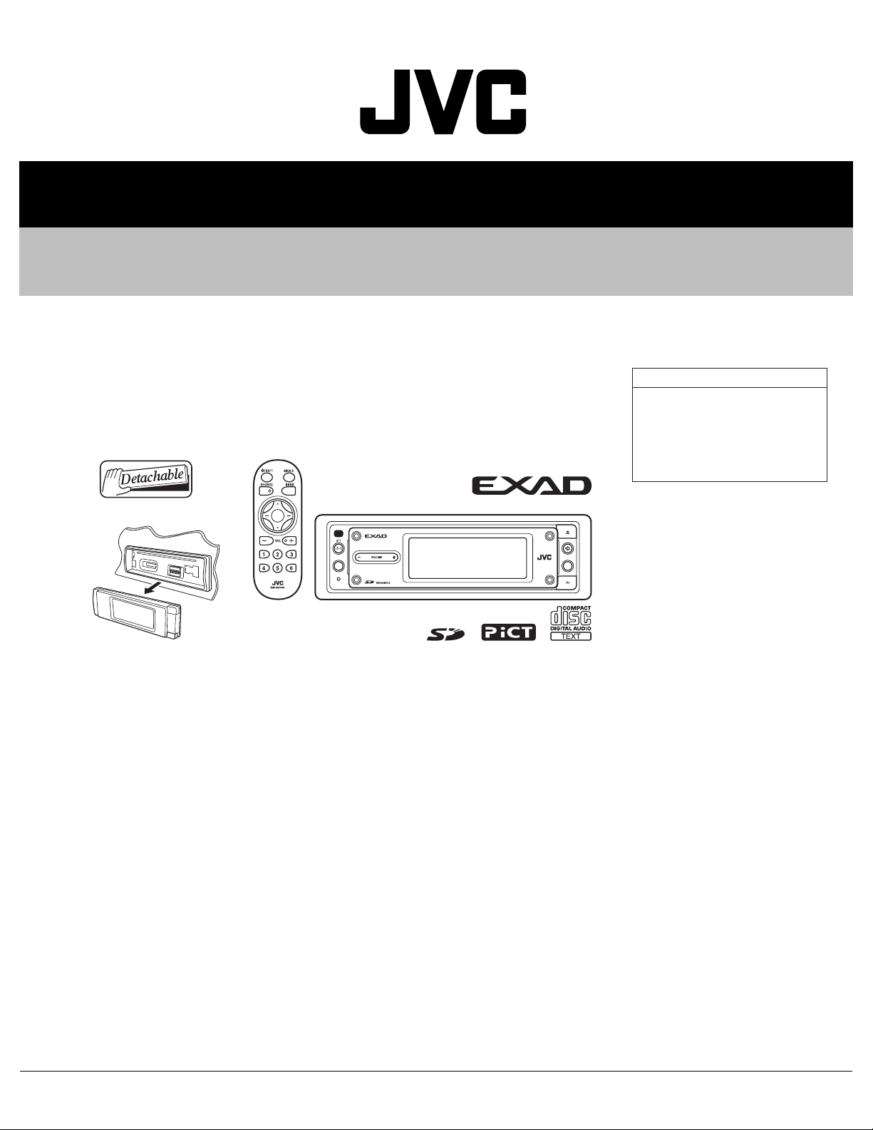
SERVICE MANUAL
CD/SD RECEIVER
MA15920053
KD-LHX555
KD-LHX555
Area suffix
UT ------------------------- Taiwan
UH ----------------------- Thailand
UN ---------------------- Indonesia
U --------------------- Other Areas
MENU
DISP
TABLE OF CONTENTS
1 PRECAUTIONS . . . . . . . . . . . . . . . . . . . . . . . . . . . . . . . . . . . . . . . . . . . . . . . . . . . . . . . . . . . . . . . . . . . . . . . 1-3
2 SPECIFIC SERVICE INSTRUCTIONS . . . . . . . . . . . . . . . . . . . . . . . . . . . . . . . . . . . . . . . . . . . . . . . . . . . . . . 1-6
3 DISASSEMBLY . . . . . . . . . . . . . . . . . . . . . . . . . . . . . . . . . . . . . . . . . . . . . . . . . . . . . . . . . . . . . . . . . . . . . . . 1-7
4 ADJUSTMENT . . . . . . . . . . . . . . . . . . . . . . . . . . . . . . . . . . . . . . . . . . . . . . . . . . . . . . . . . . . . . . . . . . . . . . . 1-23
5 TROUBLESHOOTING . . . . . . . . . . . . . . . . . . . . . . . . . . . . . . . . . . . . . . . . . . . . . . . . . . . . . . . . . . . . . . . . . 1-34
COPYRIGHT © 2005 Victor Company of Japan, Limited
No.MA159
2005/3
Page 2
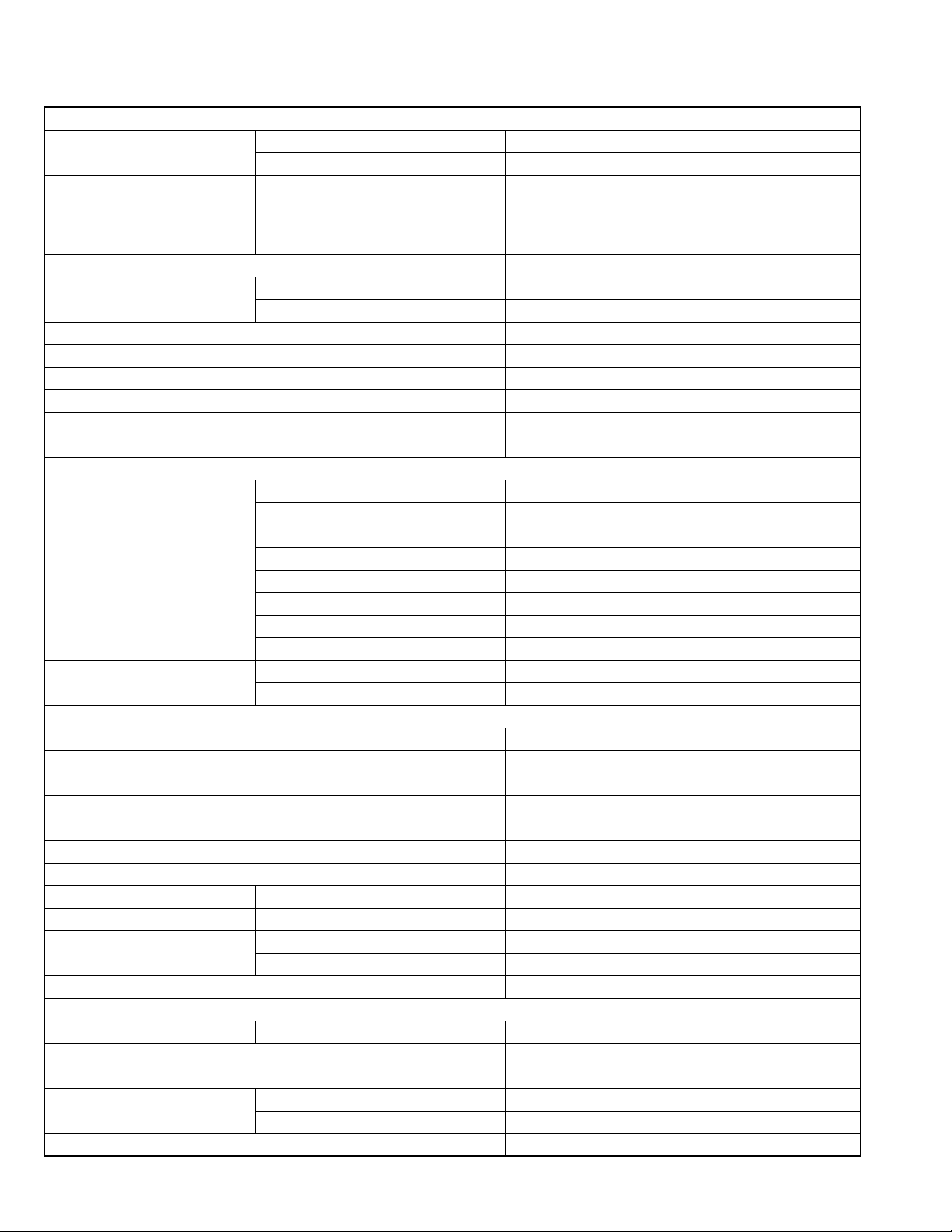
SPECIFICATION
AUDIO AMPLIFIER SECTION
Maximum Power Output Front 52 W per channel
Rear 52 W per channel
Continuous Power Output (RMS) Front 19 W per channel into 4 Ω, 40 Hz to 20 000 Hz at no more
than 0.8% total harmonic distortion.
Rear 19 W per channel into 4 Ω, 40 Hz to 20 000 Hz at no more
than 0.8% total harmonic distortion.
Load Impedance 4 Ω (4 Ω to 8 Ω allowance)
Equalizer Control Range Frequencies 60 Hz, 150 Hz, 400 Hz, 1 kHz, 2.4 kHz, 6 kHz, 12 kHz
Level ±10 dB
Frequency Response 40 Hz to 20 000 Hz
Signal-to-Noise Ratio 70 dB
Line-Out Level/Impedance 5.0 V/20 kΩ load (full scale)
Output Impedance 1 kΩ
Subwoofer-Out Level/Impedance 5.0 V/20 kΩ load (full scale)
Other Terminals LINE IN, CD changer
TUNER SECTION
Frequency Range FM 87.5 MHz to 108.0 MHz
AM 531 kHz to 1 602 kHz
FM Tuner Usable Sensitivity 11.3 dBf (1.0 µV/75 Ω)
50 dB Quieting Sensitivity 16.3 dBf (1.8 µV/75 Ω)
Alternate Channel Selectivity (400 kHz) 65 dB
Frequency Response 40 Hz to 15 000 Hz
Stereo Separation 35 dB
Capture Ratio 1.5 dB
AM Tuner Sensitivity 20 µV
Selectivity 65 dB
CD/SD PLAYER SECTION
Type Compact disc player
Signal Detection System Non-contact optical pickup (semiconductor laser)
Number of Channels 2 channels (stereo)
Frequency Response 5 Hz to 20 000 Hz
Dynamic Range 98 dB
Signal-to-Noise Ratio 102 dB
Wow and Flutter Less than measurable limit
MP3 (MPEG Audio Layer 3) Max. Bit Rate 320 kbps
WMA (Windows Media Audio) Max. Bit Rate 192 kbps
Playable SD Card Format Fat 12/16
Storage Up to 512 MB
Playable Audio Format for SD Card MP3/WMA
GENERAL
Power Requirement Operating Voltage DC 14.4 V (11 V to 16 V allowance)
Grounding System Negative ground
Allowable Operating Temperature 0°C to +40°C
Dimensions (W × H × D) Installation Size (approx.) 182 mm × 52 mm × 159 mm
Panel Size (approx.) 188 mm × 58 mm × 13 mm
Mass (approx.) 1.9 kg (excluding accessories)
Design and specifications are subject to change without notice.
1-2 (No.MA159)
Page 3
1.1 Safety Precautions
SECTION 1
PRECAUTIONS
!
!
Burrs formed during molding may be left over on some parts of the chassis. Therefore,
pay attention to such burrs in the case of preforming repair of this system.
Please use enough caution not to see the beam directly or touch it in case of an
adjustment or operation check.
(No.MA159)1-3
Page 4
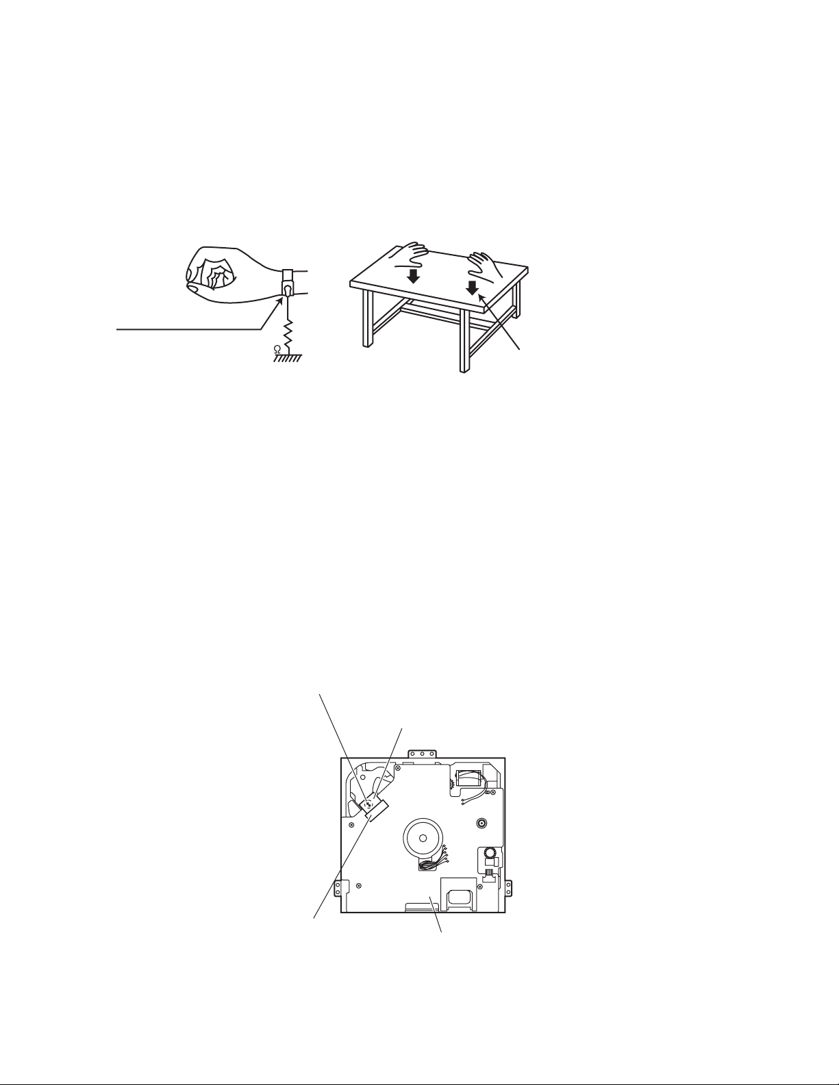
1.2 Preventing static electricity
Electrostatic discharge (ESD), which occurs when static electricity stored in the body, fabric, etc. is discharged, can destroy the laser
diode in the traverse unit (optical pickup). Take care to prevent this when performing repairs.
1.2.1 Grounding to prevent damage by static electricity
Static electricity in the work area can destroy the optical pickup (laser diode) in devices such as CD players.
Be careful to use proper grounding in the area where repairs are being performed.
(1) Ground the workbench
Ground the workbench by laying conductive material (such as a conductive sheet) or an iron plate over it before placing the
traverse unit (optical pickup) on it.
(2) Ground yourself
Use an anti-static wrist strap to release any static electricity built up in your body.
(caption)
Anti-static wrist strap
1M
Conductive material
(conductive sheet) or iron plate
(3) Handling the optical pickup
• In order to maintain quality during transport and before installation, both sides of the laser diode on the replacement optical
pickup are shorted. After replacement, return the shorted parts to their original condition.
(Refer to the text.)
• Do not use a tester to check the condition of the laser diode in the optical pickup. The tester's internal power source can easily
destroy the laser diode.
1.3 Handling the traverse unit (optical pickup)
(1) Do not subject the traverse unit (optical pickup) to strong shocks, as it is a sensitive, complex unit.
(2) Cut off the shorted part of the flexible cable using nippers, etc. after replacing the optical pickup. For specific details, refer to the
replacement procedure in the text. Remove the anti-static pin when replacing the traverse unit. Be careful not to take too long a
time when attaching it to the connector.
(3) Handle the flexible cable carefully as it may break when subjected to strong force.
(4) It is not possible to adjust the semi-fixed resistor that adjusts the laser power. Do not turn it.
1.4 Attention when traverse unit is decomposed
*Please refer to "Disassembly method" in the text for the CD pickup unit.
• Apply solder to the short land before the flexible wire is disconnected from the connector on the CD pickup unit.
(If the flexible wire is disconnected without applying solder, the CD pickup may be destroyed by static electricity.)
• In the assembly, be sure to remove solder from the short land after connecting the flexible wire.
Short sections
Flexible wire
1-4 (No.MA159)
CN601
Mechanism control board
Page 5
1.5 Important for laser products
!
1.CLASS 1 LASER PRODUCT
2.DANGER : Invisible laser radiation when open and inter
lock failed or defeated. Avoid direct exposure to beam.
3.CAUTION : There are no serviceable parts inside the
Laser Unit. Do not disassemble the Laser Unit. Replace
the complete Laser Unit if it malfunctions.
4.CAUTION : The CD,MD and DVD player uses invisible
laser radiation and is equipped with safety switches which
prevent emission of radiation when the drawer is open and
the safety interlocks have failed or are defeated. It is
dangerous to defeat the safety switches.
5.CAUTION : If safety switches malfunction, the laser is able
to function.
6.CAUTION : Use of controls, adjustments or performance of
procedures other than those specified here in may result in
hazardous radiation exposure.
Please use enough caution not to
see the beam directly or touch it
in case of an adjustment or operation
check.
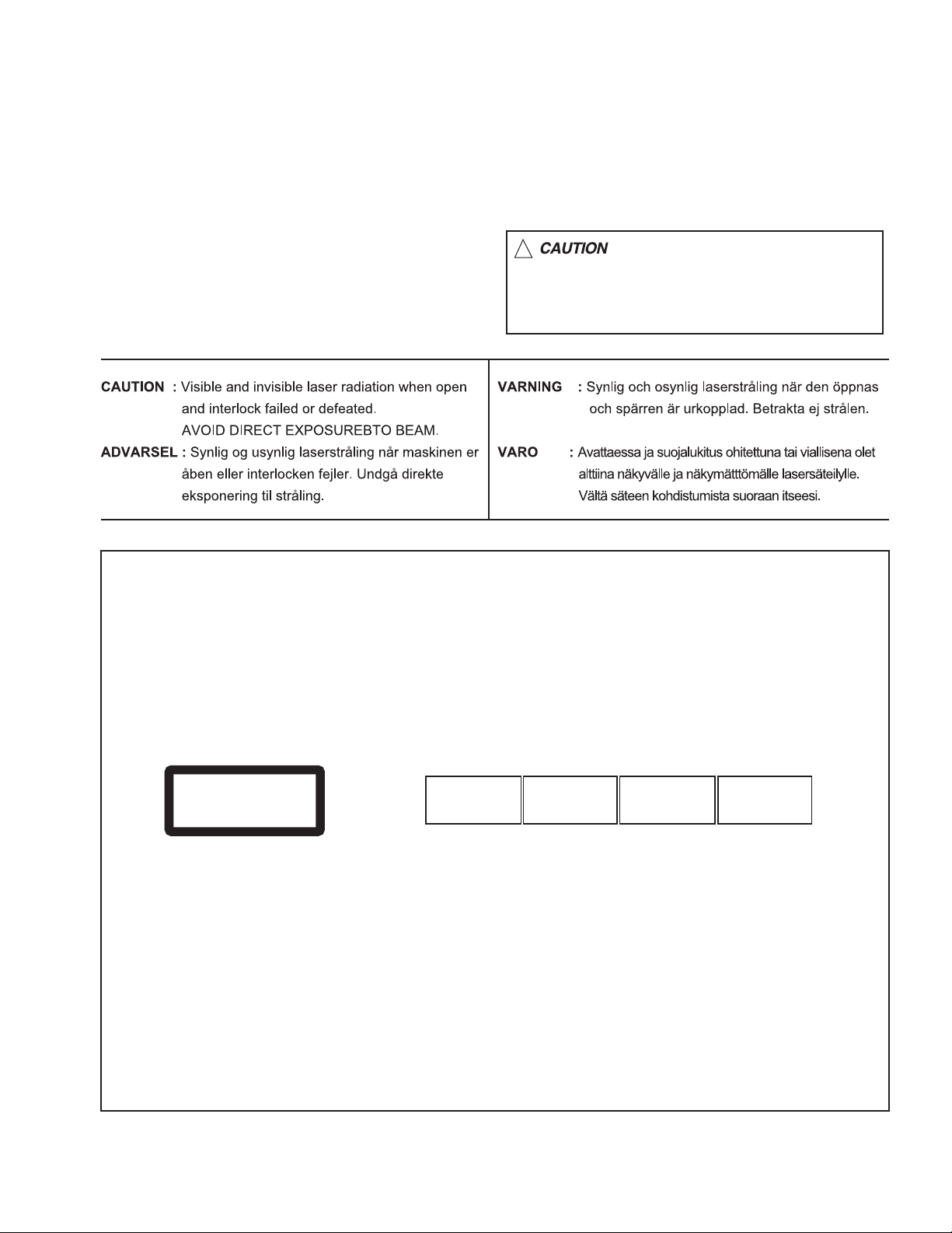
REPRODUCTION AND POSITION OF LABELS
WARNING LABEL
CAUTION : Visible and Invisible
CLASS 1
LASER PRODUCT
laser radiation when open and
interlock failed or defeated.
AVOID DIRECT EXPOSURE TO
BEAM. (e)
ADVARSEL : Synlig og usynlig
laserstråling når maskinen er
åben eller interlocken fejeler.
Undgå direkte eksponering til
stråling. (d)
VARNING : Synlig och
osynling laserstrålning när
den öppnas och spärren är
urkopplad. Betrakta ej
strålen. (s)
VARO : Avattaessa ja suojalukitus
ohitettuna tai viallisena olet alttiina
näkyvälle ja näkymättömälle
lasersäteilylle. Vältä säteen
kohdistumista suoraan itseesi. (f)
(No.MA159)1-5
Page 6

SECTION 2
SPECIFIC SERVICE INSTRUCTIONS
This service manual does not describe SPECIFIC SERVICE INSTRUCTIONS.
1-6 (No.MA159)
Page 7
SECTION 3
DISASSEMBLY
3.1 Main body section
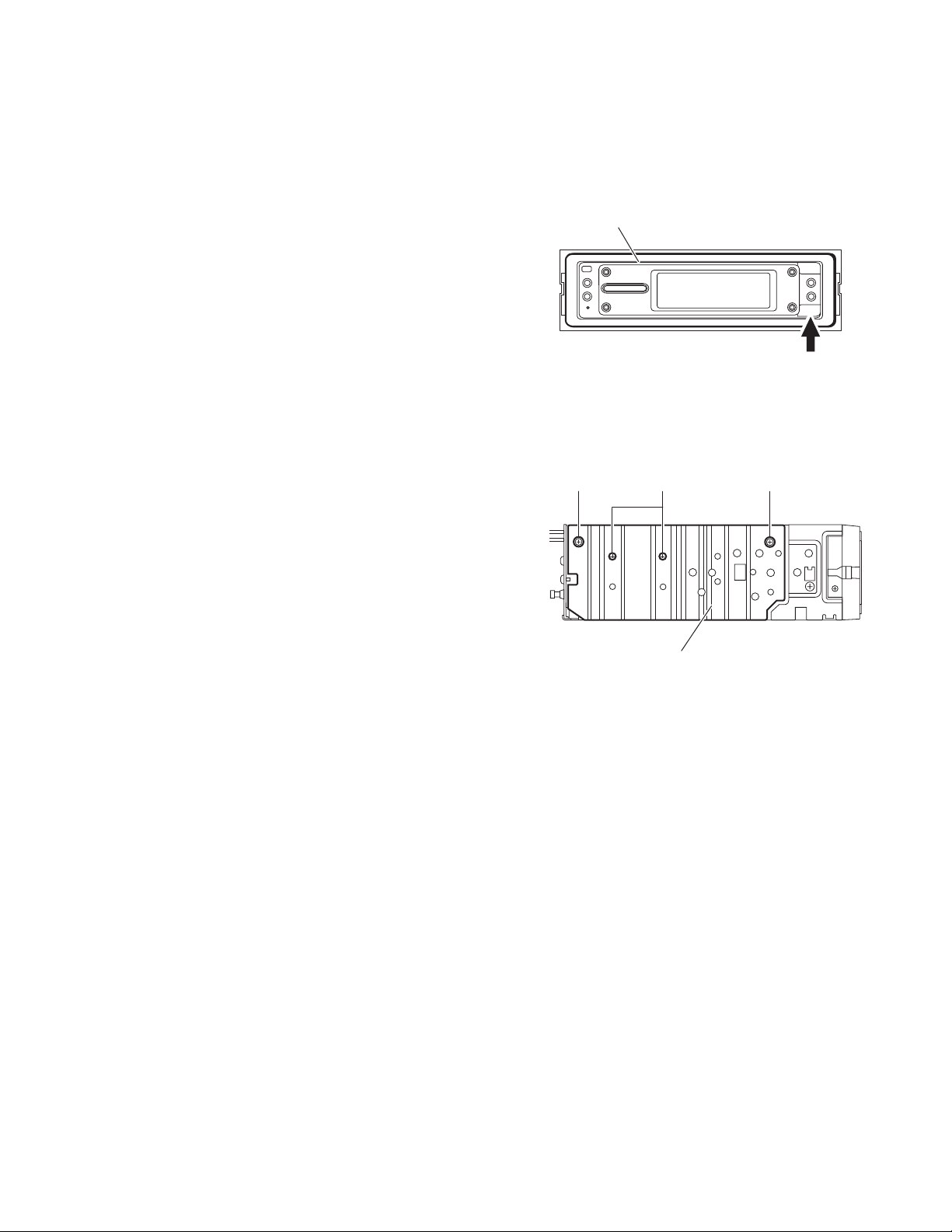
3.1.1 Removing the front panel assembly
(See Fig.1)
(1) Push the detach button in the lower right part of the front
panel assembly.
(2) Remove the front panel assembly.
3.1.2 Removing the heat sink
(See Fig.2)
Reference:
Remove the front panel assembly as required.
(1) From the left side of the main body, remove the two screws
A and three screws B attaching the heat sink.
(2) Remove the heat sink from the main body.
Front panel assembly
Detach button
Fig.1
AAB
Heat sink
Fig.2
(No.MA159)1-7
Page 8
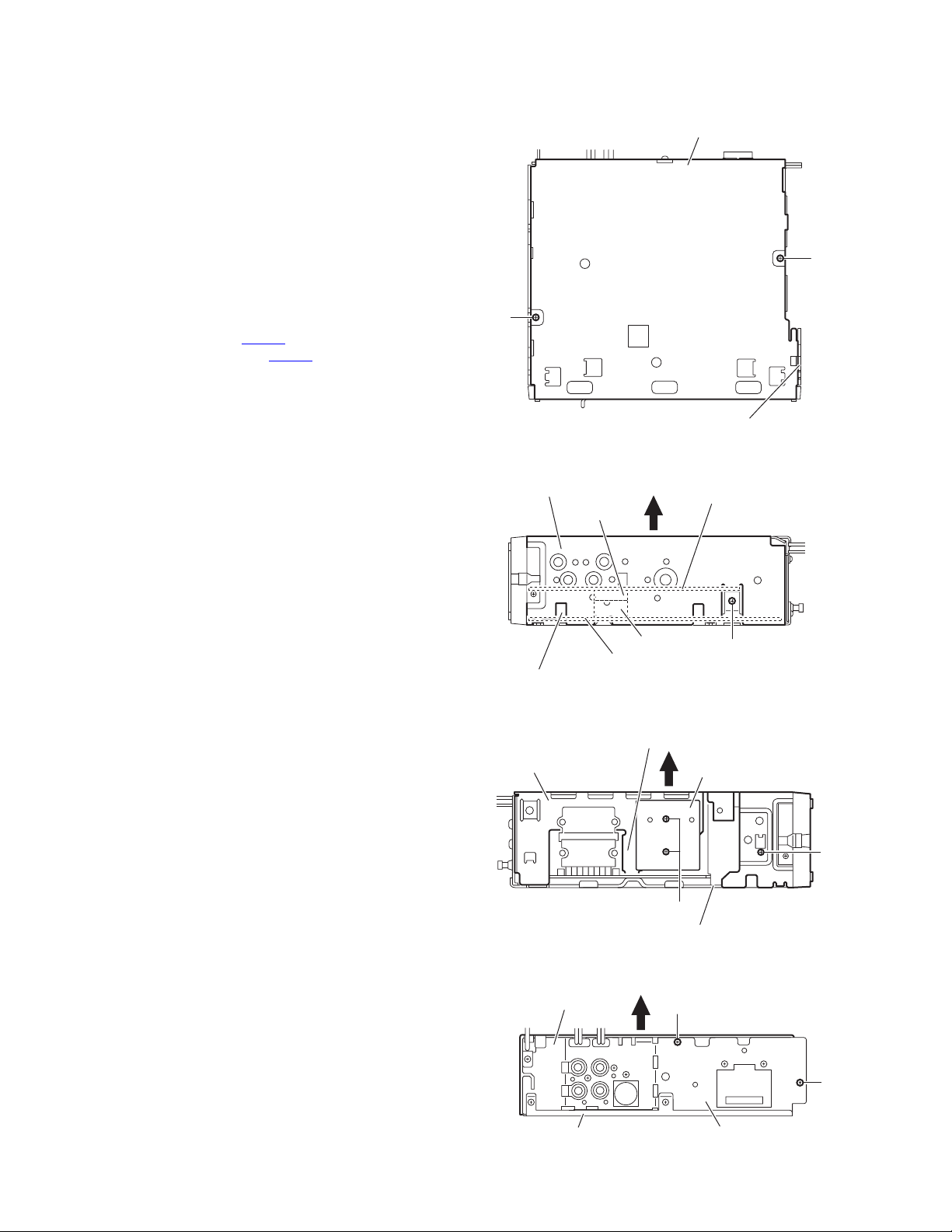
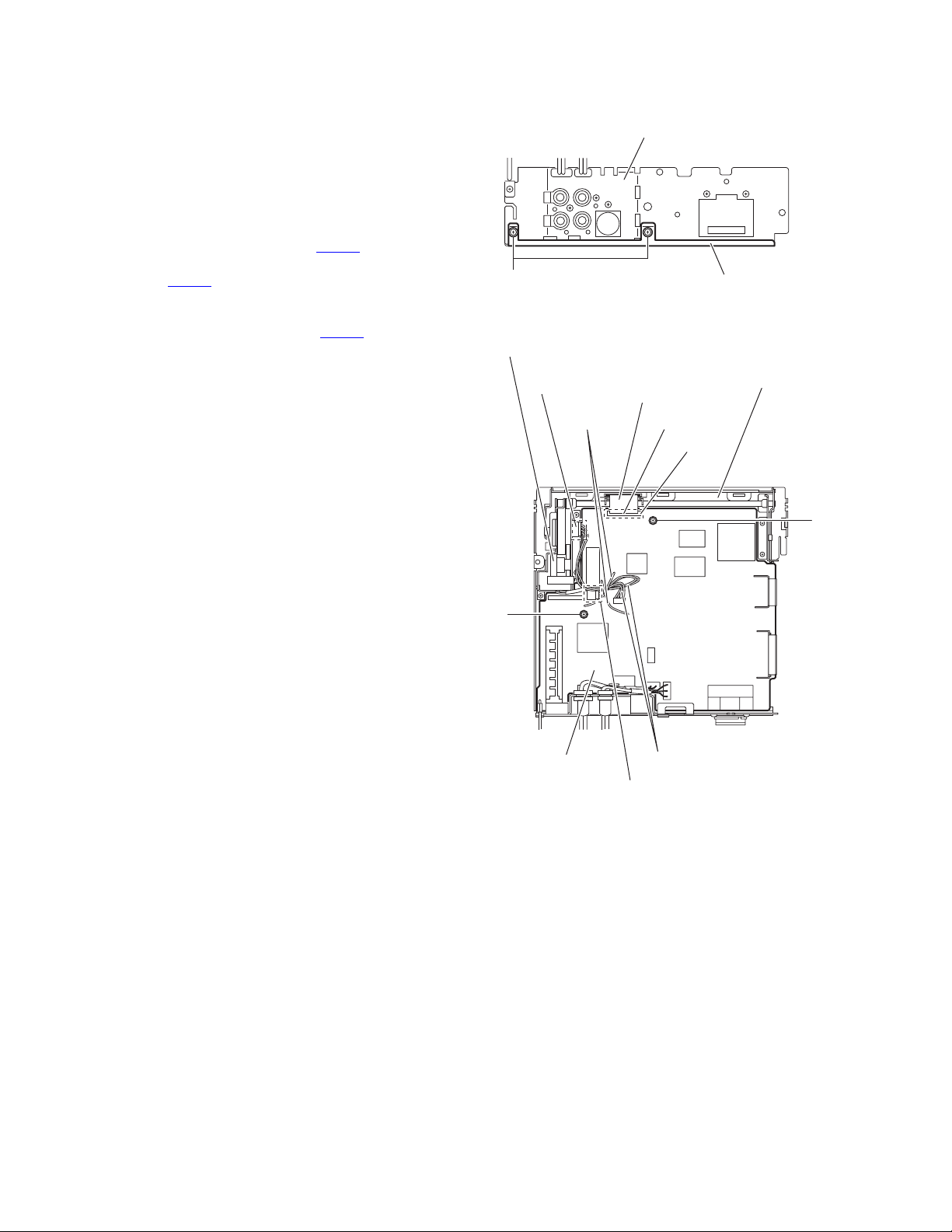
3.1.3 Removing the top chassis assembly
(See Figs.3 to 6)
• Prior to performing the following procedures, remove the heat
sink.
Reference:
Remove the front panel assembly as required.
(1) From the bottom side of the main body, remove the two
screws C attaching the top chassis assembly to the bottom
chassis assembly. (See Fig.3.)
(2) From the both and rear sides of the main body, remove the
four screws D attaching the top chassis assembly to the
bottom chassis assembly. (See Figs.4 to 6.)
(3) Remove the two screws E attaching the IC heat sink. (See
Fig.5.)
(4) Lift the top chassis assembly in the direction of the arrow,
disconnect the connector CN503
trol board from the connector CN721
(See Figs.4 to 6.)
(5) Take out the top chassis assembly from the bottom chassis
assembly.
on the mechanism con-
on the main board.
Bottom chassis assembly
C
C
Top chassis assembly
Fig.3
Top chassis assembly
CN503
Main board
Bottom chassis assembly
Mechanism control board
Top chassis assembly
Mechanism control board
CN721
Fig.4
D
IC heat sink
E
Bottom chassis assembly
D
1-8 (No.MA159)
Top chassis assembly
Bottom chassis assembly
Fig.5
D
D
Rear bracket
Fig.6
Page 9
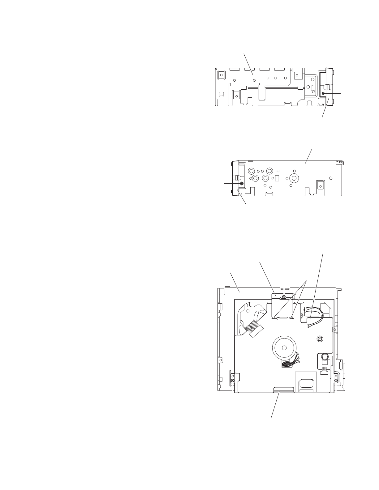
3.1.4 Removing the front chassis assembly
(See Figs.7 and 8)
• Prior to performing the following procedure, remove the front
panel assembly, heat sink and top chassis assembly.
(1) From the both sides of the top chassis assembly, remove
the two screws F attaching the front chassis assembly.
(2) Remove the front chassis assembly from the top chassis
assembly.
Top chassis assembly
F
Front chassis assembly
Fig.7
Top chassis assembly
F
Front chassis assembly
3.1.5 Removing the CD mechanism assembly
(See Fig.9)
• Prior to performing the following procedures, remove the front
panel assembly, heat sink and top chassis assembly.
Reference:
Remove the front chassis assembly as required.
(1) From the inside of the top chassis assembly, remove the
three screws G attaching the CD mechanism assembly.
(2) Release the mecha heat sink from the joints a on the mech-
anism control board and remove the heat sink from the
main body.
(3) Take out the CD mechanism assembly from the top chas-
sis.
Top chassis
Fig.8
Mechanism control board
Mecha heat sink
G
a
G G
CD mechanism assembly
Fig.9
(No.MA159)1-9
Page 10
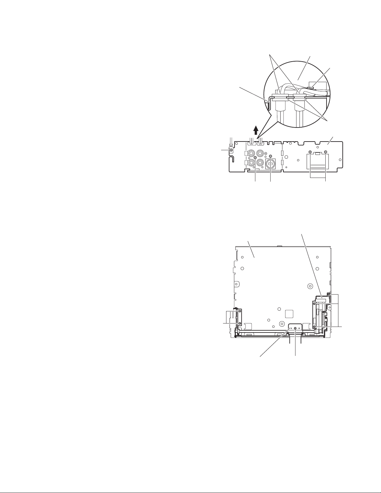
3.1.6 Removing the main board
(See Figs.10 and 11)
• Prior to performing the following procedures, remove the front
panel assembly, heat sink and top chassis assembly.
(1) From the rear side of the bottom chassis assembly, remove
the two screws H attaching the rear bracket to the bottom
chassis assembly. (See Fig.10.)
(2) From the top side of the bottom chassis assembly, remove
the two screws J attaching the main board to the bottom
chassis assembly. (See Fig.11.)
(3) Release the stopper of the connector CN701
board in an upward direction, disconnect the card wire from
the connector CN701
(4) Disconnect the wire from the connector of the front door
mechanism assembly. (See Fig.11.)
(5) Disconnect the wire from the connector CN991
board. (See Fig.11.)
Reference:
After connecting the wires, fix the wires with the wire
holders.
(6) Take out the main board from the bottom chassis assem-
bly.
. (See Fig.11.)
on the main
on the main
Rear bracket
H
Front door mechanism assembly
Connector
Wire holders
Bottom chassis assembly
Fig.10
Card wire
CN701
Stopper
Bottom chassis assembly
J
J
Main board
Wires
CN991
Fig.11
1-10 (No.MA159)
Page 11
3.1.7 Removing the rear bracket
(See Fig.12)
• Prior to performing the following procedures, remove the front
panel assembly, heat sink, top chassis assembly and main
board.
(1) From the rear side of the main board, remove the wires
from the rear bracket in the direction of the arrow.
(2) Remove the screw K and four screws L attaching the rear
bracket to the main board.
Reference:
After attaching the rear bracket to the main board, pass the
wires through the wire holder and insert them into the slots of
the rear bracket.
3.1.8 Removing the front door mechanism assembly
(See Fig.13)
• Prior to performing the following procedures, remove the front
panel assembly, heat sink, top chassis assembly and main
board.
(1) From the top side of the bottom chassis assembly, remove
the screw M attaching the FPC guide to the bottom chassis.
(2) Remove the five screws N attaching the front door mecha-
nism assembly to the bottom chassis.
Reference:
When attaching the screws M and N, apply a locking
agent them.
(3) Take out the front door mechanism assembly from the bot-
tom chassis.
Rear bracket
K
Bottom chassis
Wires
Main board
Wire holder
Slots
Rear bracket
LL L
Fig.12
Front door mechanism assembly
N
FPC guide
N
M
Fig.13
(No.MA159)1-11
Page 12
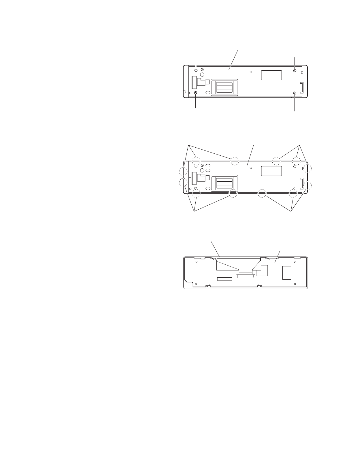
3.1.9 Removing the switch board
(See Figs.14 to 16)
• Prior to performing the following procedures, remove the front
panel assembly.
(1) From the rear side of the front panel assembly, remove the
four screws P attaching the rear cover to the front panel assembly. (See Fig.14.)
(2) Release the twelve joints b of the front panel assembly and
remove the rear cover. (See Fig.15.)
(3) Take out the switch board from the front panel assembly.
(See Fig.16.)
P
Rear cover
P
P
Fig.14
b b
b b
Front panel assembly
Rear cover
Fig.15
Switch board
Fig.16
1-12 (No.MA159)
Page 13

3.2 CD mechanism assembly section
• Remove the CD mechanism assembly from the main body.
(See "3.1.5 Removing the CD mechanism assembly".)
3.2.1 Removing the mechanism control board
(See Fig.1)
(1) From the bottom side of the CD mechanism assembly, sol-
der the short sections on the flexible wire.
Caution:
Solder the short sections on the flexible wire before disconnecting the flexible wire from the connector CN601
on the mechanism control board. If you do not follow this
instruction, the CD pickup may be damaged.
(2) Disconnect the flexible wire from the connector CN601
the mechanism control board.
(3) Disconnect the flexible wire from the connector CN602
the mechanism control board.
(4) Remove the solders from the soldered sections a on the
mechanism control board and remove the wires of the feed
motor.
(5) Remove the solders from the soldered sections b on the
mechanism control board, and remove each wire of the
spindle motor and other parts.
(6) Remove the five screws A attaching the mechanism con-
trol board.
Caution:
When reassembling, remove the solders from the short sections after connecting the flexible wire to the connector CN601
on the mechanism control board.
on
on
Short sections
Flexible wire
CN601
A
CD mechanism assembly
A
A
Spindle motor
Mechanism control board
Fig.1
Feed motor
b
A
a
A
CN602
(No.MA159)1-13
Page 14

3.2.2 Removing the top cover
r
(See Fig.2)
(1) From the back side of the CD mechanism assembly, re-
move the two screws B attaching the top cover.
(2) Take out the top cover in an upward direction.
Reference:
When attaching the top cover, set the sections c of the top cover under the bending sections d of the chassis base 2.
3.2.3 Removing the mechanism section
(See Figs.2 to 4)
• Remove the mechanism control board and top cover.
(1) From the front side of the CD mechanism assembly, re-
move the two screws C attaching the right and left stoppers. (See Fig.2.)
(2) Remove the two floating springs on the bottom side of the
CD mechanism assembly. (See Fig.3.)
(3) Take out the mechanism section in an upward direction
and remove the three damper springs from the dampers.
(See Fig.4.)
Caution:
• When reassembling the mechanism section, reattach the
damper springs to the dampers respectively and insert the
three shafts on the bottom of the mechanism section to the
dampers. (See Fig.4.)
• Before inserting the shaft to the dampers, apply IPA to the
hole of damper.
Floating spring
Fig.3
Mechanism section
C
Stopper
Top cover
Stopper
C
Fig.2
B
Chassis base 2
d
Damper
spring(F)
c
(Green)
B
Damper
(Black)
Damper
spring(F)
(Green)
Damper
(Black)
Fig.4
Damper
spring(R)
(Red)
Dampe
(Yellow)
1-14 (No.MA159)
Page 15

3.2.4 Removing the clamper unit
(See Figs.5 and 6)
• Remove the mechanism control board, top cover and mecha-
nism section.
(1) From the bottom side of the mechanism section, remove
the clamper 2 spring. (See Fig.5.)
(2) Release section e of the clamper spring from the bending
section of the CD chassis assembly. (See Fig.6.)
(3) Move the clamper unit 2 in the direction of the arrow and
release the joints (f, g). (See Fig.5.)
(4) Take out the clamper unit 2 in an upward direction. (See
Fig.5.)
3.2.5 Reattaching the clamper unit
(See Figs.5 to 9)
(1) From the bottom side of the mechanism section, attach the
clamper spring to the clamper unit 2. (See Figs.5 and 9.)
(2) Move the clamper unit 2 to set the joints (f, g) to each pro-
jection of the CD chassis assembly. (See Fig.5.)
(3) Make sure that section h of the clamper unit 2 is inserted to
the notch of the CD chassis assembly. (See Figs.5 and 8.)
(4) Move the clamper spring to the outside of the bending part
of the CD chassis assembly. (See Fig.6.)
Caution:
When reattaching the clamper unit 2, temporarily hook
the end of the clamper spring as shown in the figure to
make the work easy. (See Fig.9.)
(5) Attach the clamper 2 spring to the CD chassis assembly
and clamper unit 2. (See Figs.5 and 7.)
Clamper spring
f
Clamper 2 spring
Clamper unit 2
h
g
CD chassis assembly
Clamper spring
CD chassis assembly
Fig.5
e
Fig.6
(No.MA159)1-15
Page 16

Clamper 2 spring
Clamper unit 2
CD chassis assembly
Fig.7
Clamper unit 2
Clamper unit 2
Notch
h
Fig.8
Clamper spring
1-16 (No.MA159)
Fig.9
Page 17

3.2.6 Removing the front unit
(See Figs10 to 12)
• Remove the mechanism control board, top cover and mecha-
nism section.
(1) From the bottom side of the mechanism section, remove
the double-stick tape fixing the flexible wire. (See Fig.10.)
(2) From the top side of the mechanism section, remove the
screw D attaching the front unit 2. (See Figs.11 and 12.)
(3) Move the front unit 2 toward the front to release the joint i.
(See Figs.11 and 12.)
(4) Release two joints j and k on the right side of the CD chas-
sis assembly. (See Fig.12.)
(5) Take out the front unit 2 in an upward direction.
(6) Remove the double-stick tape fixing the flexible wire and
remove the two screws E attaching the switch wire. (See
Fig.12.)
Reference:
You can remove the switch wire only without removing the
front unit 2.
Flexible wire
Double-stick tape
Flexible
wire
j
k
E
Switch wire
D
Front unit 2
Double-stick tape
Fig.10
Front unit 2
i
CD chassis assembly
Fig.12
D
Fig.11
i
(No.MA159)1-17
Page 18

3.2.7 Removing the loading arm assembly
(See Figs.13 and 14)
• Remove the mechanism control board, top cover, mechanism
section and front unit 2.
(1) From top side of the mechanism section, move the loading
arm assembly in the direction of the arrow. (See Fig.13.)
(2) Release the projections from the right and left joints (m, n)
of the CD chassis assembly. (See Figs.13 and 14.)
(3) Release the projection from notch p of the connect arm on
the right side of the mechanism section and release the
projection from notch q of the slide cam assembly on the
left side. (See Figs.13 and 14.)
Loading arm assembly
n
CD chassis assembly
p
m
Fig.13
Loading arm assembly
Side cam
assembly
q
n
CD chassis assembly
Fig.14
m
p
Connect arm
1-18 (No.MA159)
Page 19

3.2.8 Removing the rod (L), rod (R) and roller assembly
(See Figs.15 and 16)
• Remove the mechanism control board, top cover, mechanism
section, front unit and loading arm assembly.
(1) From the bottom side of the loading arm assembly, release
the rod (L) and (R) from the joints r. (See Fig.15.)
(2) Remove the roller assembly from the loading arm assem-
bly. (See Fig.16.)
(3) Remove the two collars and washer from the roller assem-
bly. (See Fig.16.)
Caution:
After attaching the roller assembly to the loading arm assembly, attach the rod (L) and (R). Then attach the rods to the right
and left collars of the roller assembly. (See Fig.15.)
Collar
Rod(R) Rod(L)
r
Rod(R)
Roller assembly
Loading arm assembly
r
Collar
Rod(L)
r
r
Fig.15
Rod(L)
Collar
Washer
Roller assembly
Rod(R)
Collar
Loading arm assembly
Fig.16
(No.MA159)1-19
Page 20

3.2.9 Removing the CD pickup
(See Figs.17 to 19)
• Remove the mechanism control board.
(1) From the bottom side of the CD mechanism assembly, turn
the feed gear in the direction of the arrow to move the CD
pickup assembly outwards. (See Fig.17.)
(2) Remove the screw F and remove the thrust spring. (See
Fig.17.)
(3) Remove the CD pickup assembly in an upward direction
from the side of L.S. gear and release the CD pickup assembly from joint s of the sub guide. (See Fig.18.)
(4) Move the lead screw of the CD pickup assembly in the di-
rection of the arrow to release at joint t. (See Fig.18.)
(5) Remove the screw G attaching the CD rack spring and CD
rack plate on the CD pickup assembly. (See Fig.19.)
(6) Pull out the lead screw. (See Fig.19.)
Caution:
• When attaching the CD pickup assembly, attach the CD
pickup assembly at joint s of sub guide first, and attach the
lead screw to the joint t on the L.S.holder 2. (See Fig.18.)
• Perform electric adjustment after replacing the pickup.
CD mechanism assembly
CD pickup assembly
Thrust spring
Feed gear
F
Fig.17
L.S.holder 2
Sub guide
s
CD rack spring
CD rack plate
t
Lead screw
L.S. Gear
Fig.18
G
CD Pickup assembly
Lead screw
1-20 (No.MA159)
CD Pickup
Fig.19
Page 21

3.2.10 Removing the spindle motor
r
r
(See Fig.20)
• Remove the mechanism control board, top cover, mechanism
section and clamper unit.
(1) From the top side of the mechanism section, remove the
T.table assembly and washer from the spindle motor.
(2) Remove the two screws H attaching the spindle motor.
(3) Take out the spindle motor from the bottom side of the
mechanism section.
Caution:
Perform adjustment when reattaching the spindle motor.
3.2.11 Removing the feed motor
(See Figs.21 and 22)
• Remove the mechanism control board.
(1) From the bottom side of the CD mechanism assembly, re-
move the feed TRI. spring. (See Fig.21.)
(2) Remove the two screws J attaching the feed motor assem-
bly. (See Fig.21.)
(3) Remove the slit washer from the motor H. assembly and
pull out the worm wheel. (See Fig.22.)
(4) Remove the two screws K attaching the feed motor. (See
Fig.22.)
T. table assembly
Washer
Feed TRI. spring
H
Spindle moto
Fig.20
J
Feed motor assembly
Fig.21
Slit washer
Worm wheel
Feed moto
Motor H. assembly
K
Fig.22
(No.MA159)1-21
Page 22

3.2.12 Removing the SW board and rest SW board
(See Fig.23)
• Remove the mechanism control board.
(1) From the bottom side of the CD mechanism assembly, re-
move the screw L attaching the SW board.
(2) Remove the screw M attaching the rest SW board.
CD mechanism assembly
ML
Rest SW boardSW board
Fig.23
1-22 (No.MA159)
Page 23

SECTION 4
ADJUSTMENT
4.1 Adjustment method
Test instruments required for adjustment
(1) Digital oscilloscope (100MHz)
(2) Electric voltmeter
(3) Digital tester
(4) Tracking offset meter
(5) Test Disc JVC :CTS-1000
(6) Extension cable for check
EXTDV001-20P × 1
Standard volume position
Balance and Bass &Treble volume : lndication"0"
Loudness : OFF
How to connect the extension cable for adjusting
Caution:
Be sure to attach the heat sink and rear bracket onto the power amplifier IC and regulator IC respectively, before supply the power.
If voltage is applied without attaching these parts, the power amplifier IC and regulator IC will be destroyed by heat.
Standard measuring conditions
Power supply voltage DC14.4V(10.5 to 16V)
Load impedance 20KΩ(2 Speakers connection)
Output Level Line out 5.0V (Vol. MAX)
Dummy load
Exclusive dummy load should be used for AM,and FM. For FM
dummy load,there is a loss of 6dB between SSG output and
antenna input.The loss of 6dB need not be considered since
direct reading of figures are applied in this working standard.
Extension cable: EXTDV001-20P
Heat sink
Rear bracket
(No.MA159)1-23
Page 24

4.2 Service mode
4.2.1 Service mode setting
(1) Push POWER BOTTON (Power ON)
(2) Set to service mode
By pushing and holding "DISP" + "VOLUME +" + touch panel "upper right" sequentially.
"VOLUME +" button
SERVICE MODE3 (MENU)
PRODUCT
DSP TUNER
MODE
S MODE
SERVICE
MODE
DSP TUNER
Adjust
RUNNING
MODE
VOICE
CHECK
SERVICE MODE (MENU)
2
St
1:37
TUNER
No Name
87.5
-P
TOUCH PANEL
DATA
CLEAR
BACK
VERSION CD DATA
ROM COLLE
READ
NON
"DISP" button
P+
FLAT
MHz
FM1
12
5
6748
ERR READ
BACK
VERSION
VERSION
MAIN
CD V
CH V
CD DATA READ (MENU)
ADJ NOW ADJ INIT OTHERS
3
****
X
DSP
Y
V
Version display
V
* Termal AD value
Panel microcom version display
Display ROM version display
BACK
BACK
CD ERROR READ (MENU)
CD ERR
CH ERR MECHA ERR
TDSP ERR
BACK
CD ERROR
CD ERR
******
******
******
******
2
3
4
5
E1
E2
E3
1
CH ERROR
CH ERR
******
******
******
******
2
3
4
5
E1
E2
E3
1
******
******
******
******
******
******
******
******
CD error display
* Display by error code chart
BACK
CD changer error display
* Display by error code chart
BACK
MECHA ERROR
MECHA ERR
******
2
******
******
******
3
4
5
******
******
******
******
E1
E2
E3
1
DSP TUNER ERROR
TDSP ERROR
RETRY
RETRY NG
A
B
TOTAL
TOTAL
***
***
Door mecha error display
* Display by error code chart
BACK
DSP tuner error display
* The number of times of the
communication error at the time of
Power ON is displayed.
BACK
1-24 (No.MA159)
Page 25

A
B
ROM COLLECTION
DATA
READ
DATA
CLEAR
Don't used
BACK
DATA READ (No disc)
PLEASE INSERT
DATA CD
BACK
DATA READING
NOW . . .
DATA CLEAR
DON'T TOUCH ANY KEY
SUCCESS
SUCCESS!!
***
VER
PLEASE EJECT CD
Return to normal display
FALL
five seconds after
FALL
PLEASE EJECT CD
RUNNING1 MODE(MENU)
RUNNING1
3
MECHA
RUNNING2
MECHA
DATA CLEAR (MENU)
EPROM
CLEAR
4
CH ERROR
CLEAR
NAME
CLEAR
MECHA ERR
CLEAR
RUNNING3
MECHA
BACK
RUNNING1 MECHA
RUNNING1
Count
Error
RUNNING2 MECHA
RUNNING2
Count
Error
RUNNING3 MECHA
RUNNING3
Count
Error
CD ERROR
CLEAR
PICTURE
CLEAR
BACK
MECHA
MECHA
MECHA
DATA CLEAR
NOW . . .
DATA CLEAR
BACK
Running mode1
Running count
Door error during running mode
by error code chart
BACK
Running mode2
Running count
Door error during running mode
by error code chart
BACK
Running mode3
Running count
Door error during running mode
by error code chart
BACK
Return to normal display
Don't clear
Return to normal display
five seconds after
five seconds after
EPROM CLEAR
EPROM all clear & Flash ROM all clear
NOW . . .
EPROM CLEAR
(Following all contents are cleared.)
BACK
NAME CLEAR
NOW . . .
NAME CLEAR
C
D
EPROM (DISC NAME) clear
BACK
(No.MA159)1-25
Page 26

C
D
CD ERROR CLEAR
NOW . . .
CD ERROR CLEAR
EPROM (CD ERROR) clear
Error code history elimination
BACK
CH ERROR CLEAR
EPROM (CH ERROR) clear
NOW . . .
CH ERROR CLEAR
Error code history elimination
BACK
MECHA ERROR CLEAR
EPROM ( MECHA ERROR) clear
NOW . . .
MECHA ERR CLEAR
Error code history elimination
BACK
PICTURE CLEAR
NOW . . .
FM DATA(FM:Standard)
FM DATA
5
EEPROM
VIEW
VER=J021
87.5 MHz SM= 0%
MP=100%
A
dj
= 49%
BW=5
AM DATA (AM: Common )
VER=J021
87.5 MHz SM= 0%
MP=100%
A
dj
= 49%
BW=5
DSP TUNER SERVICE MODE (FM:RDS) (MENU)
VER=J021
87.5 MHz SM= 0%
MP=100%
dj
= 49%
A
BW=5
FM received
Without RDS model
BACK
FM received
BACK
AM received
BACK
FM received
Only used RDS model
BACK
RDS_DATA
****
SPI=
***
***.**
*******
**
EON
*
STREO
*
VER= V
PI=
PTY=
TP/TA= */
MS/DI= */
RDS_AF
AF
****.**
;
****.**
****.**
****.**
****.**
,
****.**
,
****.**
,
****.**
RDS_AFHOLD
MF=
***.**
AF=
Flags
SM=
MP=
Adj=
***
***
***
PI=
%
SM=
MP=
%
%
Adj=
PICTURE CLEAR
***
SM=
***
MHz
MP=
***
dj
=
***
A
*
BW=
****.**
;
****.**
,
****.**
,
****.**
,
***.**
SM= 0%
****
MP=100%
***
%
dj
= 49%
A
***
%
BW=5
***
%
EPROM ROM (all PICTURE) clear
BACK
ONLY USED WITH RDS MODEL
%
%
%
;
,
,
,
Only used RDS model
BACK
It is made to scroll upwards
for every second.
BACK
BACK
E
1-26 (No.MA159)
RDS_ENGINEER
PIC
=
SMTH2
=
SM L
=
SSM2
=
*****
******
******
******
AFC
=
Mp
=
*****
******
MORE
MORE
BACK
MORE
BACK
SYNC
=
STTH1
=
Adj
=
SMM1
=
*
******
MORE
******
******
F
For the reason for production,
please do not choose with service.
Operation will become unusual if
an unsuitable setup is carried out.
G
Page 27

E
F
EPROM VIEW
EPROM
** ** ** ** ** ** ** **
** ** ** ** ** ** ** **
** ** ** **
BACK
G
RDS_ENGINNER (ADJUST)
SYNC
SYNC
=
*
Default
Enter
BACK
PIC
PIC
=
*****
Default
Enter
BACK
AFC
AFC
=
*****
Default
Enter
BACK
SMITH1
SMITH
=
******
Default
Enter
BACK
SMITH2
SMITH2
******
=
Mp
Mp
******
=
Adj
Adj
=
******
SM L
SM L
******
=
SMM1
SMM1
******
=
SMM2
SMM2
=
******
Default
Default
Default
Default
Default
Default
Enter
BACK
Enter
BACK
Enter
BACK
Enter
BACK
Enter
BACK
Enter
BACK
ONLY USED WITH RDS MODEL
H
(No.MA159)1-27
Page 28

H
AUTO ADJ
MANUAL ADJ
AUTO ADJ
It is not used for the item used inside at the time of manufacture.
AUTO ADJ
1
87.5MHz
FM DAA
40dBuV 0%
BACK
AUTO ADJ
1
87.5MHz
FM DAA
40dBuV 0%
No Signal
BACK
AUTO ADJ
2
97.9MHz
AUTO ADJ
3
108.0MHz
AUTO ADJ
4
108.0MHz
AUTO ADJ
5
97.9MHz
AUTO ADJ
6
97.9MHz
Lch
AUTO ADJ
7
97.9MHz
AUTO ADJ
8
999kHz
AUTO ADJ
9
999kHz
AUTO ADJ
10
999kHz
FM DAA
40dBuV 0%
FM DAA
40dBuV 0%
FM S.METER
40dBuV 0%
FM S.METER
70dBuV 0%
FM FULL SP
70dBuV 0%
40kHZmod 1kHZ
FM IF CUMT
70dBuV 0%
AM S.METER
26dBuV 0%
AM S.METER
56dBuV 0%
AM IF CUNT
56dBuV 0%
BACK
BACK
BACK
BACK
BACK
BACK
BACK
BACK
BACK
AUTO ADJ
2
97.9MHz
AUTO ADJ
3
108MHz
AUTO ADJ
4
108MHz
AUTO ADJ
5
97.9MHz
AUTO ADJ
6
97.9MHz
AUTO ADJ
7
97.9MHz
AUTO ADJ
8
999kHz
AUTO ADJ
9
999kHz
AUTO ADJ
10
999kHz
FM DAA
40dBuV 0%
No Signal
FM DAA
40dBuV 0%
No Signal
FM S.METER
40dBuV 0%
No Signal
Low Signal
H Signal
FM S.METER
70dBuV 0%
No Signal
Low Siganl
H Signal
FM FULL SP
70dBuV 0%
No Signal
Adjust NG
FM IF CUMT
70dBuV 0%
No Signal
Low Signal
H Signal
AM S.METER
26dBuV 0%
No Signal
Low Signal
H Signal
AM S.METER
56dBuV 0%
No Signal
Low Signal
H Signal Low Signal
H Signal
AM IF CUNT
56dBuV 0%
No Signal
Adjust NG
BACK
BACK
BACK
BACK
BACK
BACK
BACK
BACK
BACK
J
1-28 (No.MA159)
AUTO ADJ
Completed
BACK
END
Page 29

J
MANUAL ADJ
It will be used if ther are directions.
1
87.5MHz
MANUAL ADJ
FM DAA
40dBuV 0%
Press here
87.5MHz
BACK
MANUAL
1
FM DAA
40dBuV 0%
No Signal
BACK
2
97.9MHz
3
108.0MHz
4
108.0MHz
5
97.9MHz
6
97.9MHz
Lch
7
97.9MHz
8
999kHz
9
999kHz
10
999kHz
MANUAL ADJ
FM DAA
40dBuV 0%
MANUAL ADJ
FM DAA
40dBuV 0%
MANUAL ADJ
FM S.METER
40dBuV 0%
MANUAL ADJ
FM S.METER
70dBuV 0%
MANUAL ADJ
FM FULL SP
70dBuV 0%
40kHZmod 1kHZ
MANUAL ADJ
FM IF CUMT
70dBuV 0%
MANUAL ADJ
AM S.METER
26dBuV 0%
MANUAL ADJ
AM S.METER
56dBuV 0%
MANUAL ADJ
AM IF CUNT
56dBuV 0%
Press here
BACK
Press here
BACK
Press here
BACK
Press here
BACK
Press here
BACK
Press here
BACK
Press here
BACK
Press here
BACK
Press here
BACK
2
97.9MHz
3
108MHz
4
108MHz
5
97.9MHz
6
97.9MHz
7
97.9MHz
8
999kHz
9
999kHz
10
999kHz
MANUAL
FM DAA
40dBuV 0%
No Signal
MANUAL
FM DAA
40dBuV 0%
No Signal
MANUAL
FM S.METER
40dBuV 0%
No Signal
Low Signal
H Signal
MANUAL
FM S.METER
70dBuV 0%
No Signal
Low Siganl
H Signal
MANUAL
FM FULL SP
70dBuV 0%
No Signal
Adjust NG
MANUAL
FM IF CUMT
70dBuV 0%
No Signal
Low Signal
H Signal
MANUAL
AM S.METER
26dBuV 0%
No Signal
Low Signal
H Signal
MANUAL
AM S.METER
56dBuV 0%
No Signal
Low Signal
H Signal
MANUAL
AM IF CUNT
56dBuV 0%
No Signal
Adjust NG
BACK
BACK
BACK
BACK
BACK
BACK
BACK
BACK
BACK
Completed
BACK
END
(No.MA159)1-29
Page 30

4.2.2 Detailed CD error code
Error
Pickup movement error
1.Time over of pickup movement
in an inner direction(10s)
2.Time over of pickup movement
in an outer direction(10s)
Focus serch error
Focus is not adjusted by
3-round focus serch
Tracking balance adjustment error
Time over(1s)
TOC area search error
Time over(10s)
Focus balance adjustment error
Time over(2s)
Focus gain adjustment error
Time over(0.6s)
Details of error Error code
Time over at PUBWD and PUFWD
by monitoring RESET SW
Pickup cannot move in an inner
direction.RESET SW is not on
Pickup cannot move in an outer
direction.RESET SW is not off
When foucus is not adjusted by
3-round(1set) focus serch after
disc change or focus shock,
the result is NG
Tracking balance adjustment is
not finished 1s after adjustment
command(TBA) is executed
TOC area search is not finished
after 10s
Focus balance adjustment is
not finishied 2s after the adjustment
command(FBA) is executed
Foucus gain adjustment error is not
finished 0.6s after the adjustment
command(FGA) is executed
04
04
81
82
80
82
82
Detailed error code
0051
0052
0053
0054
0055
0056
0057
Tracking gain adjustment error
Time over(0.6s)
TOC read error
Time over(30s)
1st track access error
Time over(10s)
Last track access error
Time over(10s)
Q code read error
Time over(0.6s)
TEXT data read error
RF read error
SPT analysis error
Tracking gain adjustment error
is not finished 0.6s after the
adjustment command(TGA) is
executed
TOC read operation is not
finished after 30s
1st track access is not finished
10s after TOC reading is finished
Last track access is not finished
10s after 1st track in running mode
Q code is not read for 0.6s during
playback of TOC and program
area
ALL TEXT data are not read
RF is not read
RFOK is recognized as L
SPT processing is not finished
within the timer
82
84
80
80
80
80
81
84
0058
0059
0060
0061
0062
0063
0064
0065
FAT analysis error
1-30 (No.MA159)
SPT analysis is not successful
FAT processing is not finished
within the timer
FAT analysis is not successful
84
84
84
0066
0067
0068
Page 31

4.2.3 Detailed error code of mechanism error
Error
Disc loading error
1.B1 Time out
2.B2 Time out
3.C1 Time out
4.C2 Time out
5.D1 Time out
6.D2 Time out
7.E1 Time out
Eject error
1.B1 Time out
2.C2 Time out
3.D2 Time out
4.E2 Time out
5.F1 Time out
Error while wating for loading
1.While waiting for loading for
15 seconds, SW1 becomes L
before stating loading motor
Details of error
When a disc is removed
Error code Detailed error code
09
09
09
09
09
09
09
01
01
01
01
01
09
0011
0012
0013
0014
0015
0016
0017
0021
0022
0023
0024
0025
0031
(No.MA159)1-31
Page 32

4.2.4 Changer mechanism error display
Symptom
Tray eject error
1.TRAYINSW TIME OVER
(TRAYINSW:L,TRAYOUTSW:H)
2.TRAYOUTSW TIME OVER
(TRAYINSW:H,TRAYOUTSW:H)
3.TRAYINSW TIME OVER
(TRAYINSW:L,TRAYOUTSW:L)
4.MAGIN SW:L H
Tray return error
1.TRAYOUTSW TIME OVER
(TRAYINSW:H,TRAYOUTSW:L)
2.TRAYINSW TIME OVER
(TRAYINSW:H,TRAYOUTSW:H)
3.TRAYIN/OUTSW TIME OVER
(TRAYINSW:L,TRAYOUTSW:L)
4.MAGIN SW:L H
Lifter up error
1.WAIT position TIME OVER
2.WAIT position TIME OVER
3.WAIT position TIME OVER
Lifter down error
1.WAIT position TIME OVER
Details Error code
Tray motor TIME OVER
Tray motor does not operate.
Tray stops.
TRAYINSW NG etc.
Magazine is ejected while Tray is
being ejected.
Tray motor TIME OVER
Tray motor does not operate.
Tray stops.
TRAYOUTSW NG etc
Magazine is ejected while Tray is
being returned.
Position motor TIME OVER
Position motor does not operate.
Position is not stable in fine
adjustment mode.
Other condition
Position motor TIME OVER
Position motor does not operate.
03
03
03
03
03
03
03
03
02
02
02
02
Detailed error code
0011
0012
0013
0014
0016
0017
0018
0019
0021
0022
0023
0026
2.WAIT position TIME OVER
3.WAIT position TIME OVER
Chucking error
1.PLAY position TIME OVER
2.PLAY position TIME OVER
3.PLAY position TIME OVER
Unchucking error
1.WAIT position TIME OVER
2.WAIT position TIME OVER
3.WAIT position TIME OVER
EJECT error
1.EJECT position TIME OVER
2.EJECT position TIME OVER
3.MAGINSW TIME OVER
Initialize error
1.Mechanism SW NG error
Position is not stable in fine
adjustment mode.
Other condition
Position motor TIME OVER
Position motor does not operate.
Position is not stable in fine
adjustment mode.
Other condition
Position motor TIME OVER
Position motor does not operate.
Position is not stable in fine
adjustment mode.
Other condition
EJECT cannot be carried out.
Position motor does not operate.
Improper EJECT position.*
Magazine is not ejected.
TRAYINSW and TRAYOUTSW are L.
02
02
02
02
02
02
02
02
02
02
01
03
0027
0028
0031
0032
0033
0036
0037
0038
0041
0042
0043
0046
2.Absolute position TIME OVER
Position is not stable in absolute
02
0047
position.*
*"Position is not stable in WAIT position," "Position is not stable in PLAY position," and "Position is not stable in
absolute position," and "Improper EJECT position" are all Position Motor TIME OVER.
1-32 (No.MA159)
Page 33

4.2.5 Error codes of panel mechanism
Error
Error in OPEN (Abnormal OPEN)
1. OPEN cannot be detected. TIME OUT
Error in CLOSE (Abnormal ANGLE1)
1. ANGLE 1 cannot be detected. TIME OUT
Error in angle adjustment
Movement to angle 10 (Abnormal ANGLE2)
1. ANGLE 2 cannot be detected in movement in OPEN direction. TIME OUT
2. ANGLE 1 is passed and ANGLE 2 is detected in movement in OPEN direction.
3. ANGLE 2 cannot be detected in movement in CLOSE direction. TIME OUT
Movement to angle 20 (Abnormal ANGLE3)
1. ANGLE 3 cannot be detected in movement in OPEN direction. TIME OUT
2. ANGLE 2 is passed and ANGLE 3 is detected in movement in OPEN direction.
3. ANGLE 3 cannot be detected in movement in CLOSE direction. TIME OUT
Movement to angle 30 (Abnormal ANGLE4)
1. ANGLE 4 cannot be detected in movement in OPEN direction. TIME OUT
2. ANGLE 3 is passed and OPEN position is detected in movement in OPEN direction.
3. ANGLE 4 cannot be detected in movement in CLOSE direction. TIME OUT
Abnormal SW condition in panel movement
When a panel is moved in a range from OPEN to CLOSE, ERR 00 is displayed when
improper SW condition is detected.
Error display in
service mode
0A01
0B06
0D21
0D22
0D23
0E31
0E32
0E33
0F41
0F42
0F43
0A00
Error display in
normal condition
ERR
01
06
21
22
23
31
32
33
41
42
43
00
4.2.6 Error history
Indication
E1**????
E2**????
E3**????
5_**????
4_**????
3_**????
2_**????
1_**????
TOTAL_??
Details
Last error
Second last error
Third last error
Fifth error
Fourth error
Third error
Second error
First error
Total amount of errors (100 errors or
more is displayed as99)
(No.MA159)1-33
Page 34

5.1 Feed section
SECTION 5
TROUBLESHOOTING
Is 2V at IC601 pin 63?
YES
Is 4V present at both
sides of the feed motor?
YES
Check the feed motor.
5.2 Focus section
5.3 Spindle section
NO
Is the wiring for IC601
pin 63 correct?
NO
Is 2V present at IC681
pins 1 and 27?
Check IC681.
When the lens is
moving:
Does the S-search
waveform appear at
IC681 pins 10 and 11?
NO
NO
YES
4V
YES
YES
Is 8V present at IC681
pins 3 and 12?
Check the vicinity of
IC601.
Check the feed motor
connection wiring.
NO
Check the circuits in
the vicinity of IC681
pins 13 and 14.
Check the pickup and
its connections.
NO
Check CD8V.
YES
YES
Is the disk rotated?
YES
Does the RF signal
appear at IC601 pin 26?
YES
Is the RF waveform
at IC601 pin 26 distorted?
YES
Proceed to the Tracking
section
5.4 Tracking section
When the disc is rotated
at first:
Is the tracking error
signal output at IC601
pin 57?
NO
Is 4V present between
IC681 pins 6 and 7?
Check the spindle motor
and its wiring.
NO
Check the circuits in
the vicinity of IC601
or the pickup.
NO
NO
Approx. 1.2V
YES
NO
YES
Check the circuits in
the vicinity of IC601
pins 48 and 49.
Is 4V present at IC601
pin 64?
YES
Check the vicinity of
IC681.
NO
Check the pickup and
its connections.
NO
Check IC601.
1-34 (No.MA159)
Check IC601.
Page 35

5.5 Signal processing section
Is the sound output from
both channels (L, R)?
YES
Normal
NO
No sound from either
channel.
Is 9V present at IC365
pin 16?
Is the audio signal
(including sampling
output components)
output to IC191/IC291
pins 1 and 7 during
playback?
Is the audio signal output
at IC171/IC271 pins 12
and 13 during playback?
YES
YES
YES
Compare the L-ch and
NO
R-ch to locate the
defective point.
NO
Is 9V present at IC901
pin 10?
Check the connection
between IC901 pin10
and IC365 pin 16.
NO
Check IC191/IC291 and
its peripheral circuits.
NO
Check IC171/IC271 and
its peripheral circuits.
YES
NO
Check IC901 and its
peripheral circuits.
YES
Check the power amp.
IC951.
(No.MA159)1-35
Page 36

5.6 16 PIN CORD DIAGRAM
8
6
5
4
3
2
1
7
BK
RD
BL
BL/WH
WH
GN
VI
GY
YL
OR/WH
NC
BR
WH/BK
GN/BK
VI/BK
GY/BK
16 YL
8 BK
7 RD
15 OR/WH
13 BR
3 GN
11 GN/BK
10
16
15
14
13
12
11
BK
RD
BL
Black
Red
Blue
WH White
BR
9
MEMORY
GND
ACC
ILL
TEL
RL+
RL-
Brown
GN
Green
VI Violet
GY
YL
Gray
Yellow
OR Orange
GND
RR
FR
FL
2 VI
10 VI/BK
4 WH
12 WH/BK
1 GY
9 GY/BK
5 BL/WH
6 BL
Rear Right
Front Right
Front Left
RR+
RR-
FL+
FL-
FR+
FR-
REMOTE
ANT
REMOTE
CAUTION!
POWER
ANT
ACC
ILL
OUTPUT ONLY
ANTENNA
Auto Antenna
ACC Line
Illuminations Control
RL
REMOTE
TEL
1-36 (No.MA159)
Rear Left
Remote out
Telephone muting
GND
MEMORY
Ground
Memory Backup Battery+
Page 37

(No.MA159)1-37
Page 38

Victor Company of Japan, Limited
AV & MULTIMEDIA COMPANY CAR ELECTRONICS CATEGORY 10-1,1chome,Ohwatari-machi,Maebashi-city,371-8543,Japan
(No.MA159)
Printed in Japan
VPT
 Loading...