

Page 1
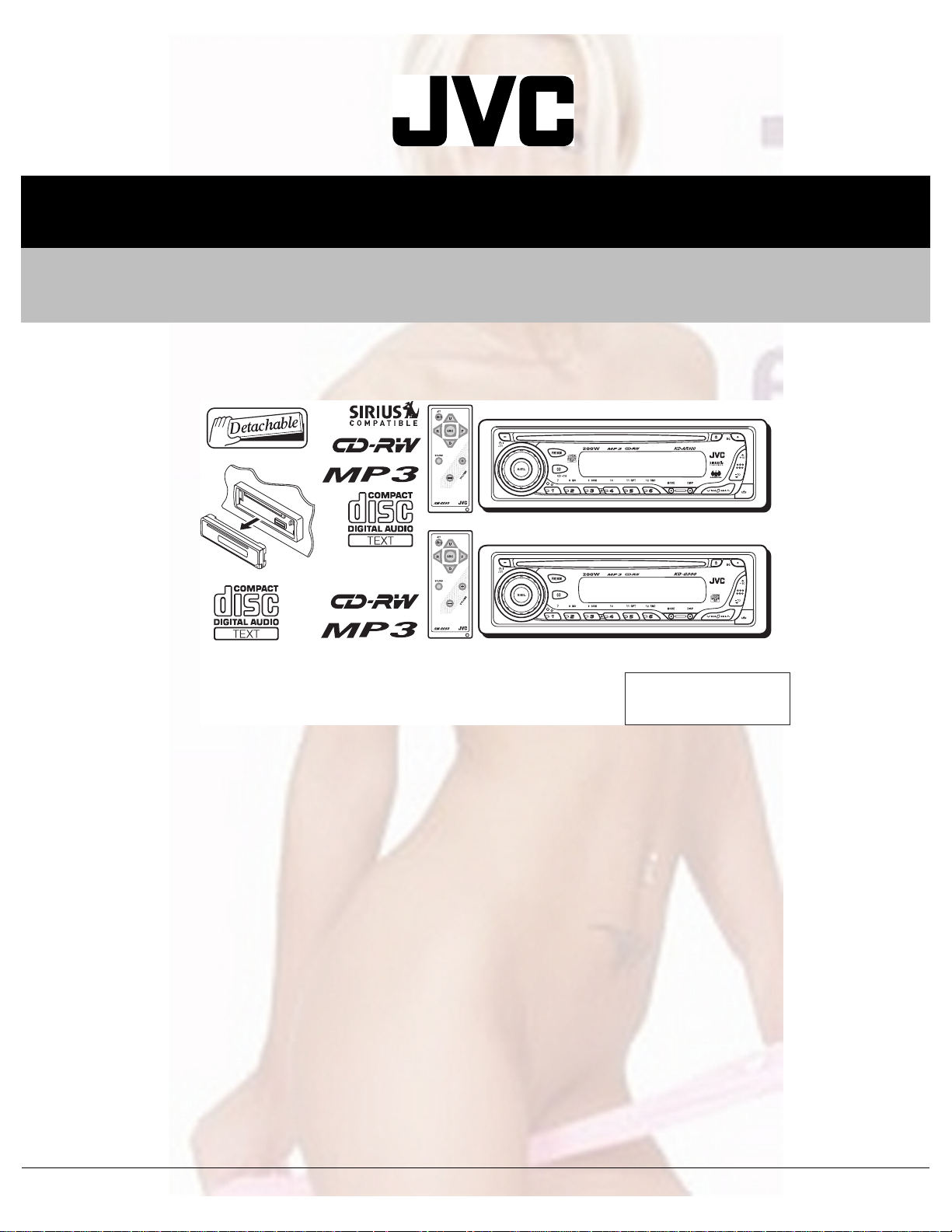
SERVICE MANUAL
CD RECEIVER
MA03620041
KD-G300, KD-AR300
KD-AR300
S
KD-G300
S
Area Suffix
J ----- Northern America
TABLE OF CONTENTS
1 PRECAUTION. . . . . . . . . . . . . . . . . . . . . . . . . . . . . . . . . . . . . . . . . . . . . . . . . . . . . . . . . . . . . . . . . . . . . . . . . 1-3
2 SPECIFIC SERVICE INSTRUCTIONS. . . . . . . . . . . . . . . . . . . . . . . . . . . . . . . . . . . . . . . . . . . . . . . . . . . . . . 1-5
3 DISASSEMBLY . . . . . . . . . . . . . . . . . . . . . . . . . . . . . . . . . . . . . . . . . . . . . . . . . . . . . . . . . . . . . . . . . . . . . . . 1-6
4 ADJUSTMENT . . . . . . . . . . . . . . . . . . . . . . . . . . . . . . . . . . . . . . . . . . . . . . . . . . . . . . . . . . . . . . . . . . . . . . . 1-24
5 TROUBLE SHOOTING. . . . . . . . . . . . . . . . . . . . . . . . . . . . . . . . . . . . . . . . . . . . . . . . . . . . . . . . . . . . . . . . . 1-25
COPYRIGHT © 2004 VICTOR COMPANY OF JAPAN, LIMITED
No.MA036
2004/1
Page 2

SPECIFICATION
AUDIO AMPLIFIER SECTION
Maximum Power Output Front 50 W per channel
Rear 50 W per channel
Continuous Power Output
(RMS)
Load Impedance 4 Ω (4 Ω to 8 Ω allowance)
Tone Control Range Bass ±10 dB at 100 Hz
Frequency Response 40 Hz to 20 000 Hz
Signal-to-Noise Ratio 70 dB
Line-Out Level/Impedance 2.5 V/20 kΩ load (full scale)
Output Impedance 1 kΩ
Frequency Range FM 87.5 MHz to 107.9 MHz
[FM Tuner] Usable Sensitivity 11.3 dBf (1.0 µV/75 Ω)
[AM Tuner] Sensitivity 20 µV
Type Compact disc player
Signal Detection System Non-contact optical pickup (semiconductor laser)
Number of channels 2 channels (stereo)
Frequency Response 5 Hz to 20 000 Hz
Dynamic Range 96 dB
Signal-to-Noise Ratio 98 dB
Wow and Flutter Less than measurable limit
MP3 decoding format MPEG1/2 Audio Layer 3
Power Requirement Operating Voltage DC 14.4 V (11 V to 16 V allowance)
Grounding System Negative ground
Allowable Operating Temperature 0ºC to +40ºC (32ºF to 104ºF)
Dimensions (W × H × D) Installation Size (approx.) 182 mm × 52 mm × 150 mm (7-3/16" × 2-1/16" × 5-15/16")
Mass (approx.) 1.4 kg (3.1 lbs) (excluding accessories)
Front 19 W per channel into 4 Ω, 40 Hz to 20 000 Hz at no more than
0.8% total harmonic distortion.
Rear 19 W per channel into 4 Ω, 40 Hz to 20 000 Hz at no more than
0.8% total harmonic distortion.
Treble ±10 dB at 10 kHz
TUNER SECTION
AM 530 kHz to 1 710 kHz
50 dB Quieting Sensitivity 16.3 dBf (1.8 µV/75 Ω)
Alternate Channel Selectivity (400 kHz) 65 dB
Frequency Response 40 Hz to 15 000 Hz
Stereo Separation 35 dB
Capture Ratio 1.5 dB
Selectivity 35 dB
CD PLAYER SECTION
Max. Bit Rate: 320 Kbps
GENERAL
Panel Size (approx.) 188 mm × 58 mm × 11 mm (7-7/16" × 2-5/16" × 7/16")
Design and specifications are subject to change without notice.
1-2 (No.MA036)
Page 3

1.1 Safety Precautions
SECTION 1
PRECAUTION
!
!
Burrs formed during molding may be left over on some parts of the chassis. Therefore,
pay attention to such burrs in the case of preforming repair of this system.
Please use enough caution not to see the beam directly or touch it in case of an
adjustment or operation check.
(No.MA036)1-3
Page 4
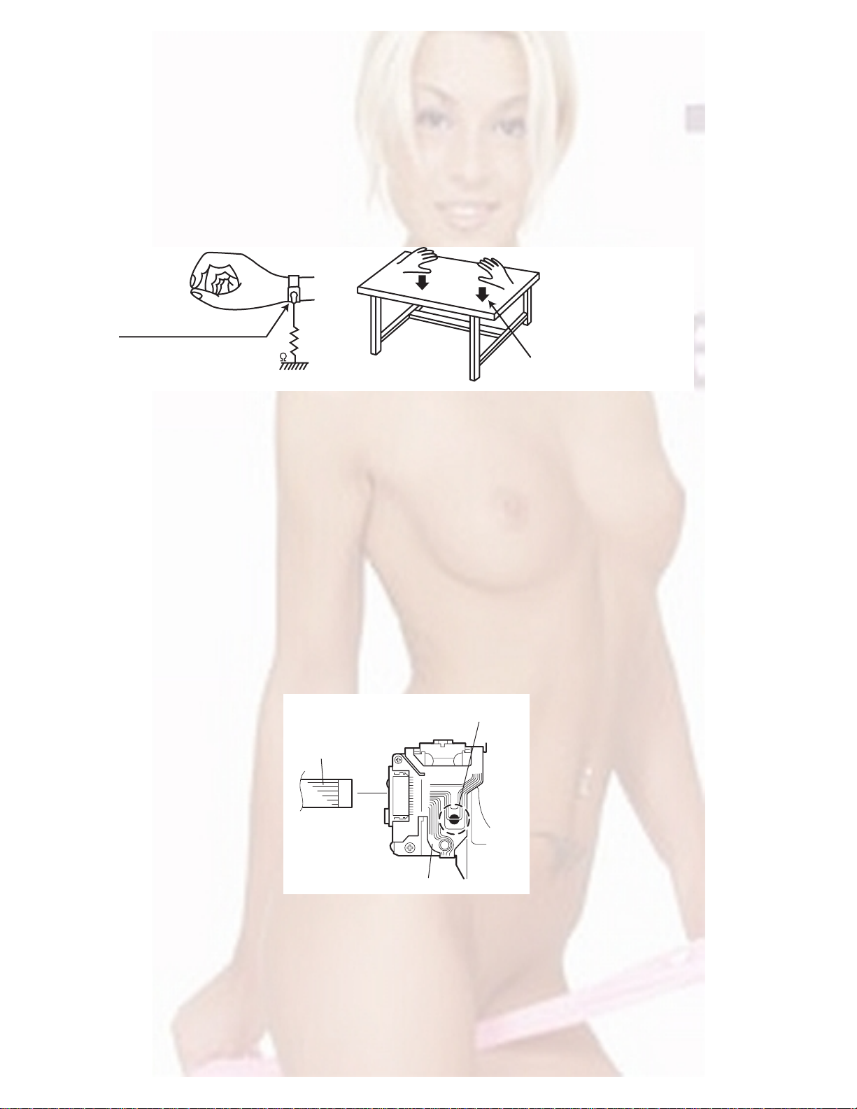
1.2 Preventing static electricity
Electrostatic discharge (ESD), which occurs when static electricity stored in the body, fabric, etc. is discharged, can destroy the laser
diode in the traverse unit (optical pickup). Take care to prevent this when performing repairs.
1.2.1 Grounding to prevent damage by static electricity
Static electricity in the work area can destroy the optical pickup (laser dio de) in devices such as CD players.
Be careful to use proper grounding in the area where repairs are being performed.
(1) Ground the workbench
Ground the workbench by laying conductive material (such as a conductive sh eet) or an iron plate over it before placing the
traverse unit (optical pickup) on it.
(2) Ground yourself
Use an anti-static wrist strap to release any static electricity built up in your body.
(caption)
Anti-static wrist strap
1M
Conductive material
(conductive sheet) or iron plate
(3) Handling the optical pickup
• In orde r to maintain quality during tra nsport and before install ation, both sides of the laser diode on the replacement optical
pickup are shorted. After replacement, return the shorted parts to their original condition.
(Refer to the text.)
• Do not use a tester to check the condition of the laser diode in the optical pickup. The tester's internal power source can easily
destroy the laser diode.
1.3 Handling the traverse unit (optical pickup)
(1) Do not subject the traverse unit (optical pickup) to strong shocks, as it is a sensitive, complex unit.
(2) Cut off the shorted part of the flexible cable using nippers, etc. after replacing the optical pickup. For specific details, refer to the
replacement procedure in the text. Remove the anti-static pin when replacing the traverse unit. Be careful not to take too long a
time when attaching it to the connector.
(3) Handle the flexible cable carefully as it may break when subjected to strong force.
(4) It is not possible to adjust the semi-fixed resistor that adjusts the laser power. Do not turn it.
1.4 Attention when traverse unit is decomposed
*Please refer to "Disassembly method" in the text for the CD pickup unit.
• Apply solder to the short land before the flexible wire is disconnected from the connector on the CD pickup unit.
(If the flexible wire is disconnected without applying solder, the CDpickup may be destroyed by static electricity.)
• In the assembly, be sure to remove solder from the short land after connecting the flexible wire.
Short-circuit point
(Soldering)
Flexible wire
1-4 (No.MA036)
Pickup
Page 5

SECTION 2
SPECIFIC SERVICE INSTRUCTIONS
This service manual does not describe SPECIFIC SERVICE INSTRUCTIONS.
(No.MA036)1-5
Page 6
SECTION 3
DISASSEMBLY
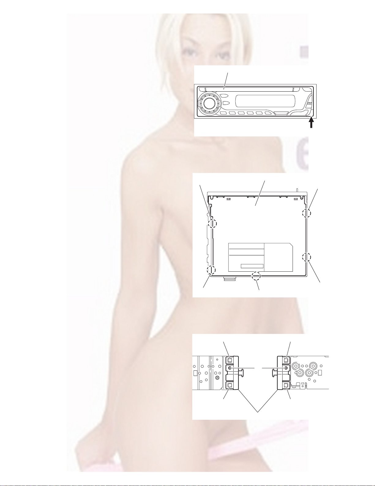
3.1 Main body
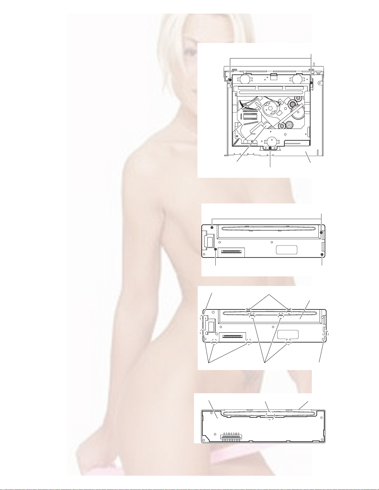
3.1.1 Removing the front panel assembly
(See Fig.1)
(1) Push the detach button in the lower right part of the front
panel assembly and remove the front panel assembly.
3.1.2 Removing the bottom cover
(See Fig.2)
(1) Turn the main body up side down.
(2) Insert a screwdriver under the joints to release the two
joints a on the left side, two joints b on the right side and
joint c on the back side of the main body, then remove the
bottom cover from the main body.
Note:
When releasing the joints using a screwdriver, do not damage
the main board.
Front panel assembly
Joint a
Detach button
Fig.1
Bottom cover
Joint b
3.1.3 Removing the front chassis assembly
(See Fig.3)
• Prior to performing the following procedures, remove the front
panel assembly and bottom cover.
(1) Remove the two screws A on the both sides of the main
body.
(2) Release the two joints d and two joints e on the both sides
of the main body, then remove the front chassis assembly
toward the front.
Joint a
Joint c
Fig.2
Joint d Joint e
A
Joint d
Front chassis assembly
Fig.3
Joint e
Joint b
1-6 (No.MA036)
Page 7
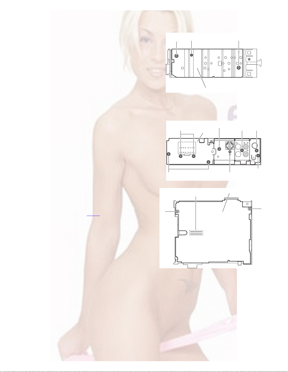
3.1.4 Removing the side panel
(See Fig.4)
• Prior to p erforming the following procedure, remove the front
panel assembly as required.
(1) Remove the screw B and two screws C attaching the side
panel on the left side of the main body, and remove the side
panel.
3.1.5 Removing the rear bracket
(See Fig.5)
• Prior to performing the following procedure, remove the bottom
cover.
(1) Remove the three screws D, three screws E and two
screws F attaching the rear bracket on the back side of the
main body.
(2) Remove the screw F’ attaching the rear bracket on the
back side of the main body. (KD-AR300J)
(3) Remove the rear bracket.
C
B
Side panel
Fig.4
EF
Rear bracket
F
C
E
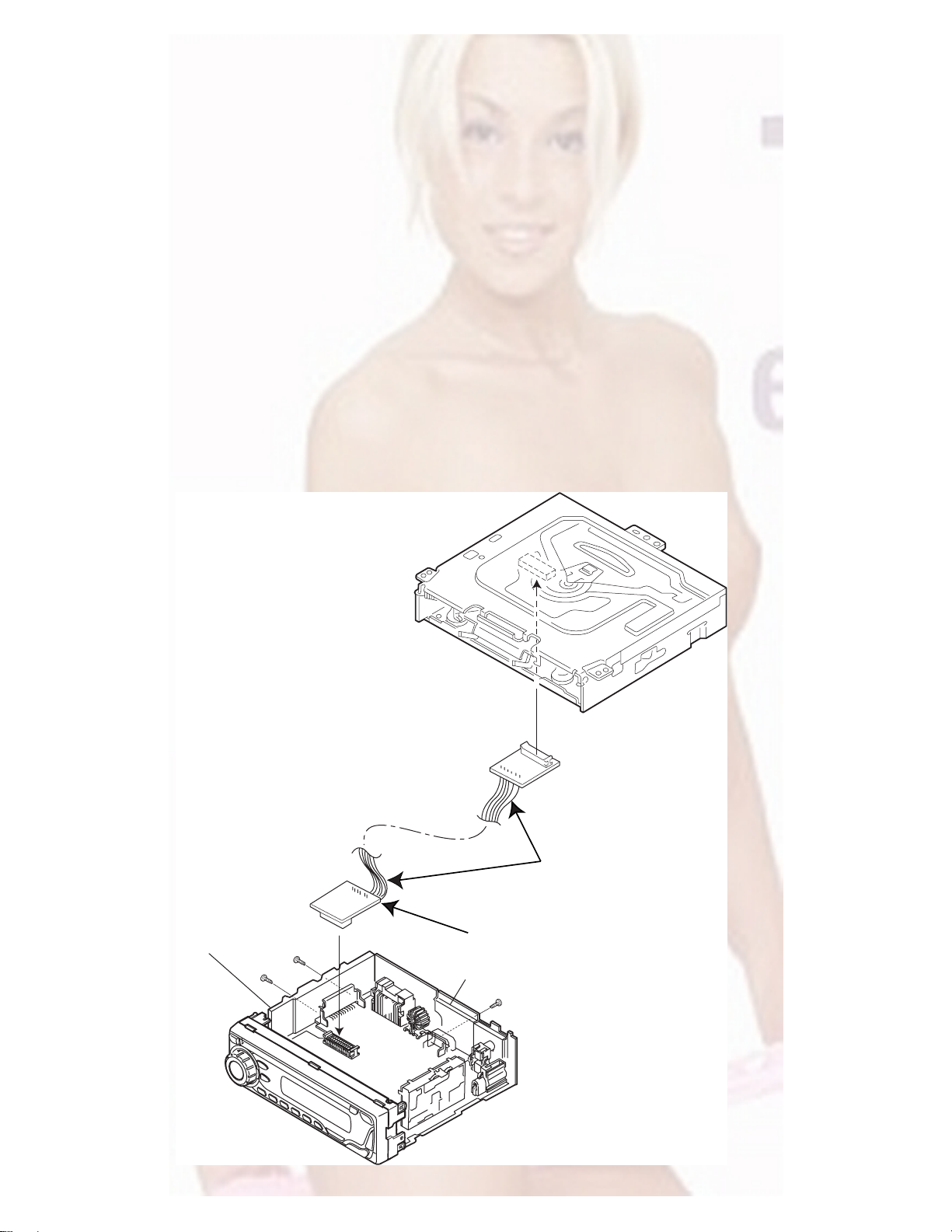
3.1.6 Removing the main board
(See Figs.5 and 6)
• Prior to performing the following procedures, remove the front
panel assembly, bottom cover and side panel.
• Remove the front chassis assembly as required.
(1) Remove the three screws D attaching the rear bracket on
the back side of the main body. (See Fig.5.)
(2) Remove the two screws G attaching the main board. (See
Fig.6.)
(3) Disconnect the connector CN501
the main body and take out the main board with the rear
bracket. (See Fig.6.)
Reference:
Remove the rear bracket from the main body as required. (See
“3.1.5 Removing the rear bracket”.)
on the main board from
G
D
CN501
Fig.5
Fig.6
F'
Main board
D
G
(No.MA036)1-7
Page 8
3.1.7 Removing the CD mechanism assembly
(See Fig. 7)
• Prior to performin g the following procedure, remove the front
panel assembly, bottom cover, side panel, rear bracket and
main board.
• Remove the front chassis assembly as required.
(1) Remove the three screws H attaching the CD mechanism
assembly on the top chassis.
(2) Take out the CD mechanism assembly.
H
3.1.8 Removing the front board
(See Figs.8 to 10)
• Prior to performing the following procedures, remove the front
panel assembly.
(1) Remove the four screws J on the back side of the front pan-
el assembly. (See Fig.8.)
(2) Release the ten joints f and remove the rear cover. (See
Fig.9.)
(3) Release the joint g and take out the front board from the
front panel assembly. (See Fig.10.)
CD mechanism assembly
J
Joint f
Top chassis
H
Fig.7
J
J
Fig.8
Joints f
Rear cover
1-8 (No.MA036)
Joints f
Front board
Joints f
Fig.9
Joint g
Fig.10
Joint f
Front panel assembly
Page 9
3.2 CD Mechanism Assembly
A
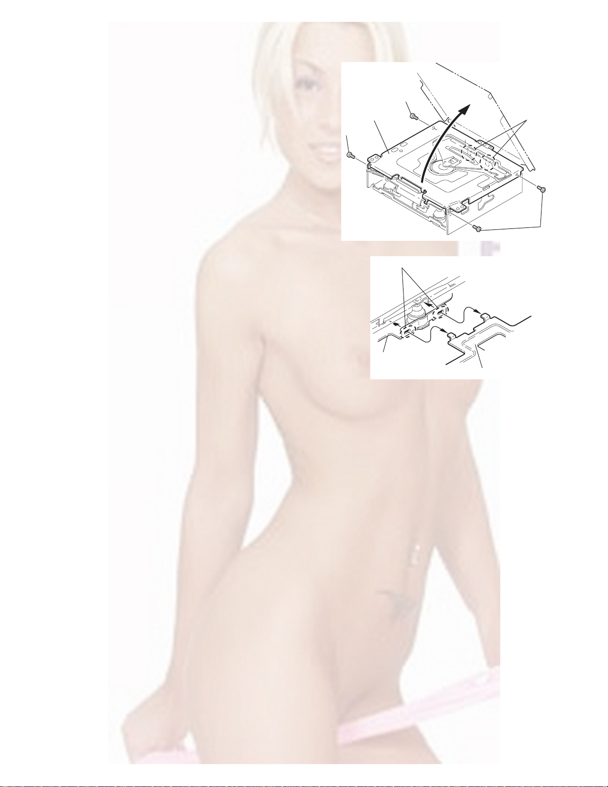
3.2.1 Removing the top cover
(See Figs.1 and 2)
(1) Remove the two screws A on the both side of the body.
(2) Lift the front side of the top cover and move the top cover
backward to release the two joints a.
Top cover
Joints a
A
Joints a
A
Fig.1
Fig.2
Top cover
(No.MA036)1-9
Page 10
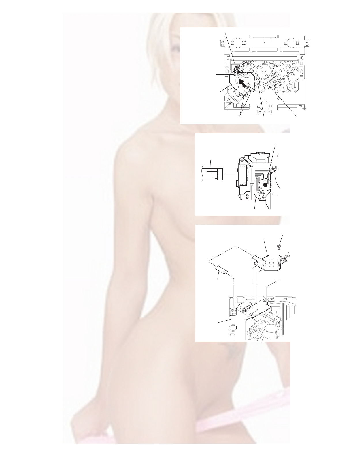
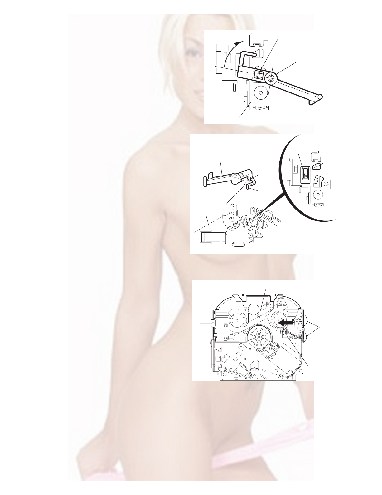
3.2.2 Removing the connector board
(See Figs.3 to 5)
CAUTION:
Before disconnecting the flexible wire from the pickup, solder
the short-circuit point on the pickup. No observance of this instruction may cause damage of the pickup.
(1) Remove the screw B fixing the connector board.
(2) Solder the short-circuit point on the connector board.
(3) Disconnect the flexible wire from the pickup.
(4) Move the connector board in the direction of the arrow to
release the two joints b.
(5) Unsolder the wire on the connector board if necessary.
CAUTION:
Unsolder the short-circuit point after reassembling.
B
Connector board
Flexible wire
Wires
Joints b
Short-circuit point
Fig.3
Short-circuit point
(Soldering)
Pickup
Flexible wire
Frame
Pickup
Fig.4
B
Connector board
Fig.5
1-10 (No.MA036)
Page 11
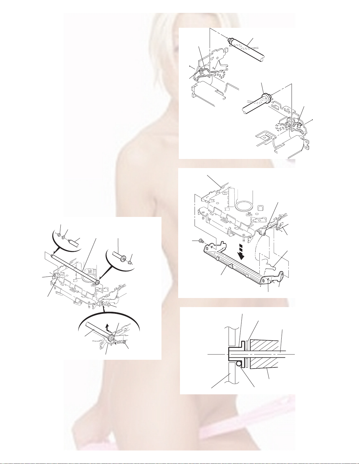
3.2.3 Removing the DET switch
(See Figs.6 and 7)
(1) Extend the two tabs c of the feed sw. holder and pull out
the switch.
(2) Unsolder the DET switch wire if necessary.
Connector
board
DET switch
DET switch
Pickup
Fig.6
Tab c
DET switch wire
Tab c
Feed sw. holder
Fig.7
(No.MA036)1-11
Page 12
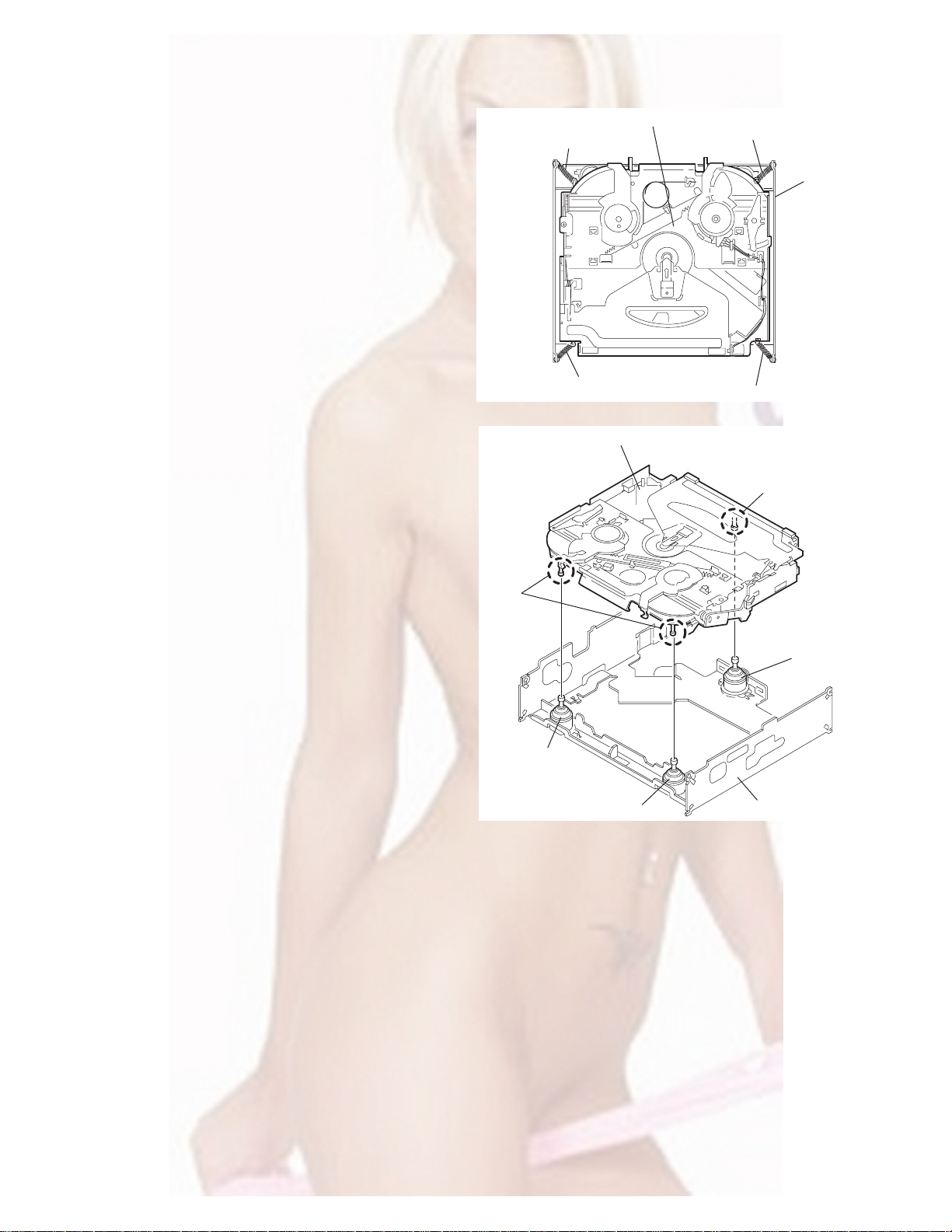
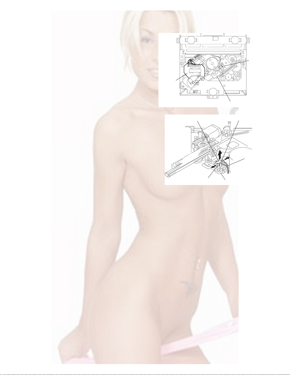
3.2.4 Removing the chassis unit
r
(See Figs.8 and 9)
• Prior to performing the follow ing procedure, remove the top
cover and connector board.
(1) Remove the two suspension springs (L) and (R) attaching
the chassis unit to the frame.
CAUTION:
• The shape of the suspension spring (L) and (R) are different. Handle them with care.
• When reassembling, make sure that the three shafts
on the underside of the chassis unit are inserted to the
dampers certainly.
Suspension spring (R)
Chassis unit
Suspension spring (L)
Frame
Suspension spring (R)
Chassis unit
Shafts
Damper
Damper
Suspension spring (L)
Fig.8
Shaft
Dampe
Frame
Fig.9
1-12 (No.MA036)
Page 13
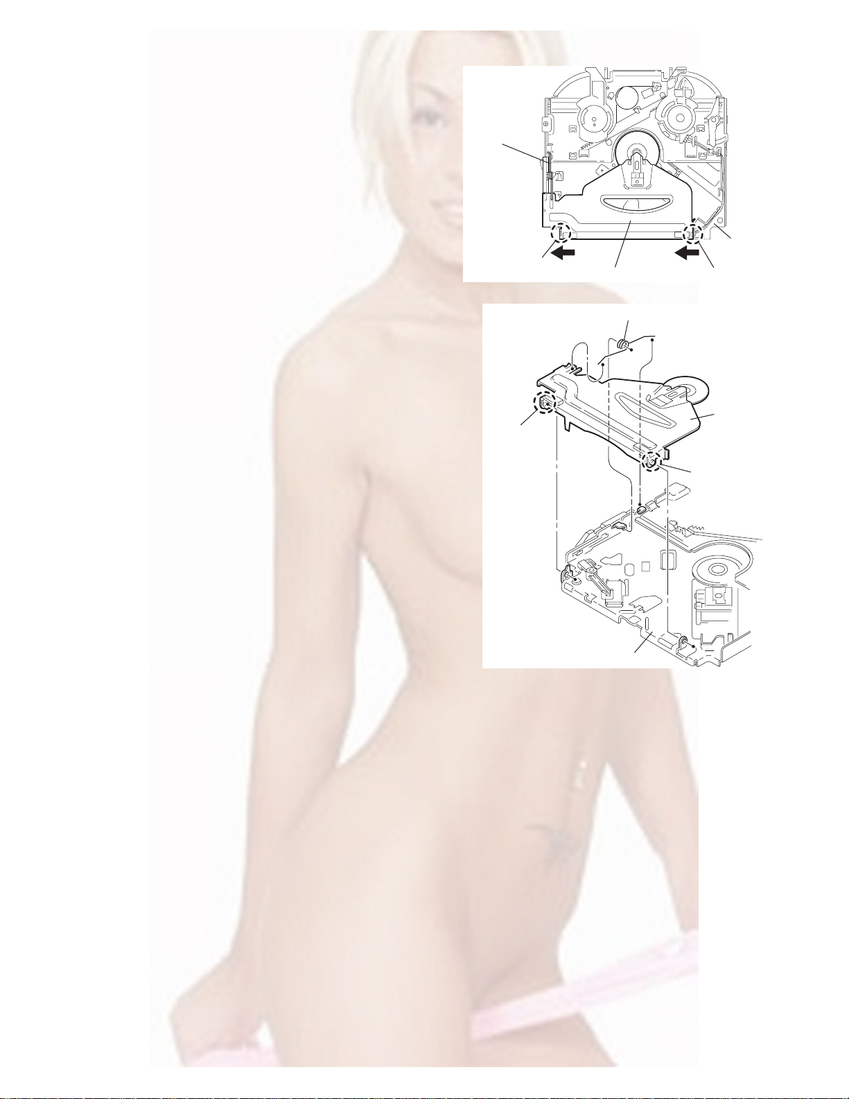
3.2.5 Removing the clamper assembly
(See Figs.10 and 11)
• Prior to p erforming the following procedure, remove the top
cover.
(1) Remove the clamper arm spring.
(2) Move the clamper assembly in the direction of the arrow to
release the two joints d.
Clamper arm
spring
Joint d
Joint d
Clamper assembly
Fig.10
Clamper arm spring
Chassis rivet
assembly
Joint d
Clamper
assembly
Chassis rivet assembly
Fig.11
Joint d
(No.MA036)1-13
Page 14
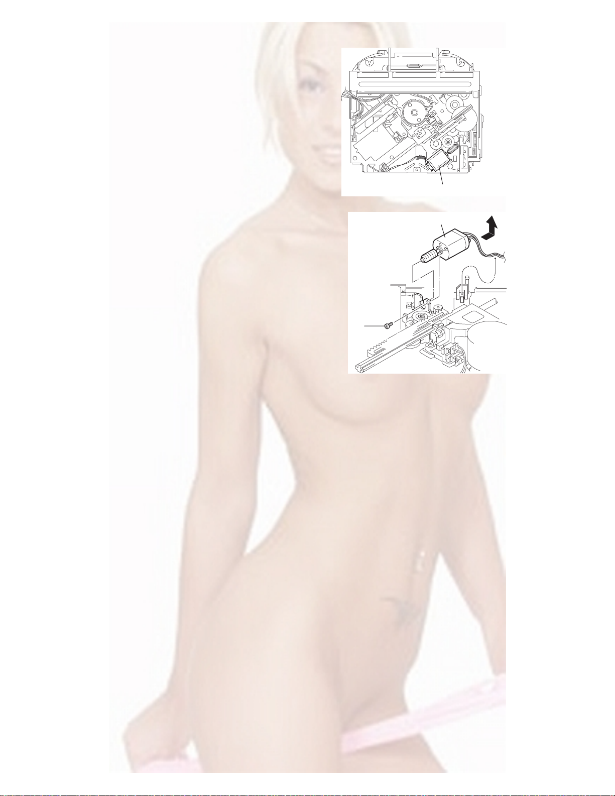
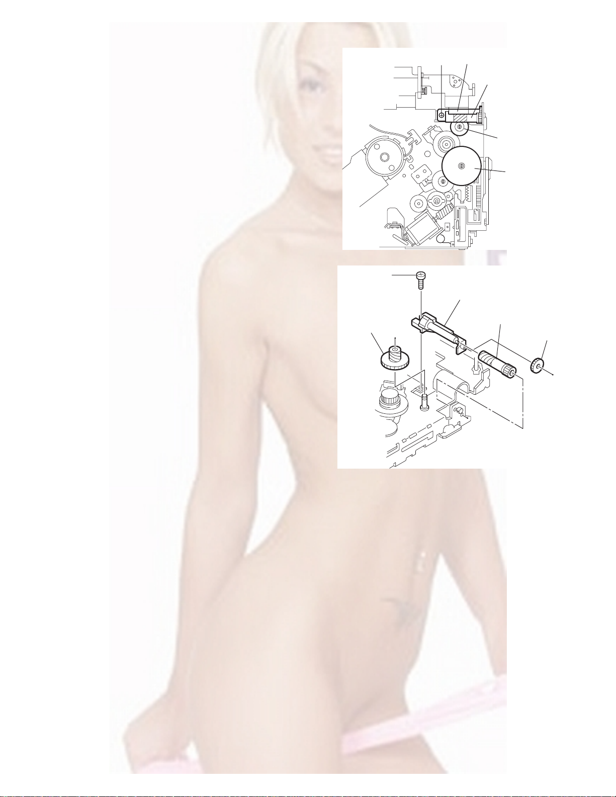
3.2.6 Removing the loading / feed motor assembly
(See Figs.12 and 13)
• Prior to performing the follow ing procedure, remove the top
cover, connector board and chassis unit.
(1) Remove the screw C and move the loading / feed motor
assembly in the direction of the arrow to remove it from the
chassis rivet assembly.
(2) Disconnect the wire from the loading / feed motor assembly
if necessary.
CAUTION:
When reassembling, connect the wire from the loadin g /
feed motor assembly to the flame as shown in Fig.12.
Loading / feed motor assembly
Fig.12
Loading / feed motor assembly
C
Fig.13
1-14 (No.MA036)
Page 15
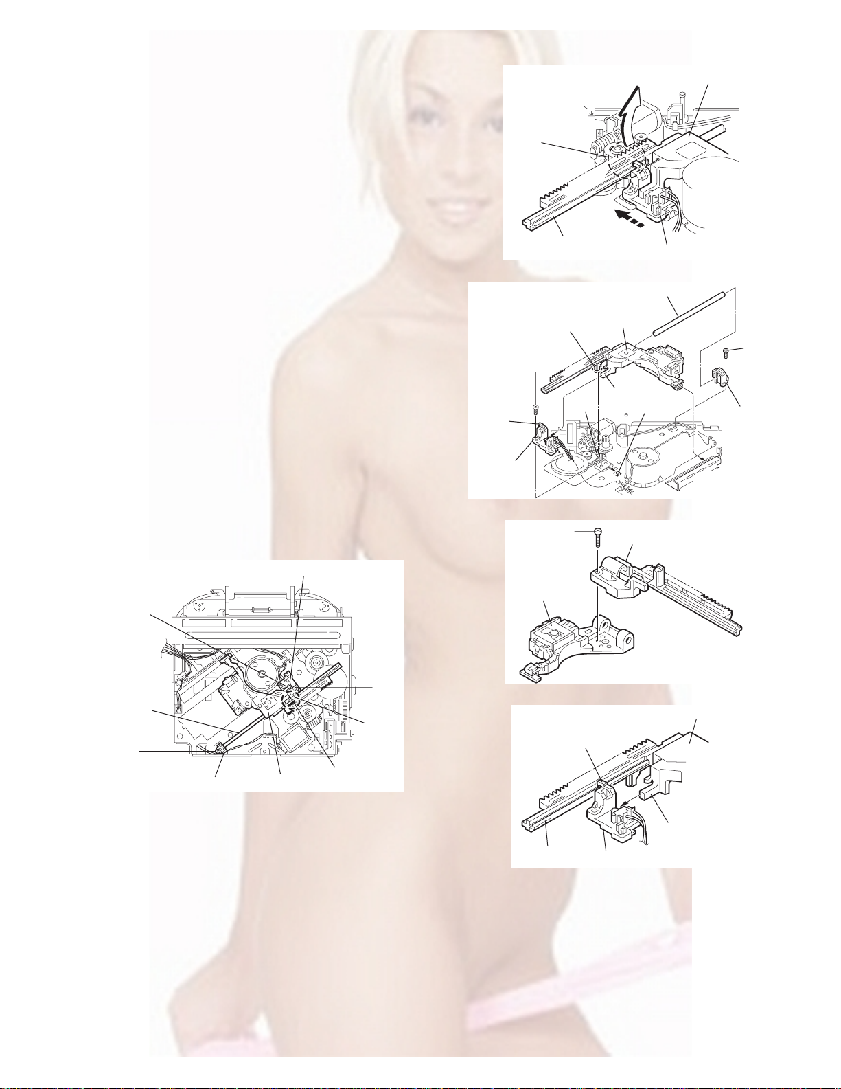
3.2.7 Removing the pickup unit
(See Figs.14 to 18)
• Prior to p erforming the following procedure, remove the top
cover, connector board and chassis unit.
(1) Remove the screw D and pull out the pu. shaft holder from
the pu. shaft.
(2) Remove the screw E attaching the feed sw. holder.
(3) Move the part e of the pickup unit upward with the pu. shaft
and the feed sw. holder, then release the joint f of the feed
sw. holder in the direction of the arrow. The joint g of the
pickup unit and the feed rack is released, and the feed sw.
holder comes off.
(4) Remove the pu. shaft from the pickup unit.
(5) Remove the screw F attaching the feed rack to the pickup
unit.
3.2.8 Reattaching the pickup unit
(See Figs.14 to 17)
(1) Reattach the feed rack to the pickup unit using the screw F.
(2) Reattach the feed sw. holder to the feed rack while setting
the joint g to the slot of the feed rack and setting the part f
of the feed rack to the switch of the feed sw. holder correctly.
(3) As the feed sw. holder is temporarily attached to the pickup
unit, set to the gear of the joint g and to the bending part of
the chassis (joint h) at a time.
CAUTION:
Make sure that the part i on the underside of the feed
rack is certainly inserted to the slot j of the change lock
lever.
(4) Reattach the feed sw. holder using the screw E.
(5) Reattach the pu. shaft to the p ickup uni t. Reattach the pu.
shaft holder to the pu. shaft using the screw D.
Feed sw. holder
Joint f
Joint g
Feed sw.
holder
Part e
Feed rack
Part i
E
Pickup unit
Slot j
F
Fig.15
Pu. shaft
Pickup unit
Joint f
Joint h
Fig.16
Feed rack
Pickup unit
Feed sw. holder
D
Pu. shaft
holder
Pu. shaft
D
Pu. shaft holder
Pickup unit
Fig.14
Part e
E
Joint g
Feed rack
Fig.17
Pickup unit
Joint g
Joint f
Feed sw. holder
Fig.18
(No.MA036)1-15
Page 16
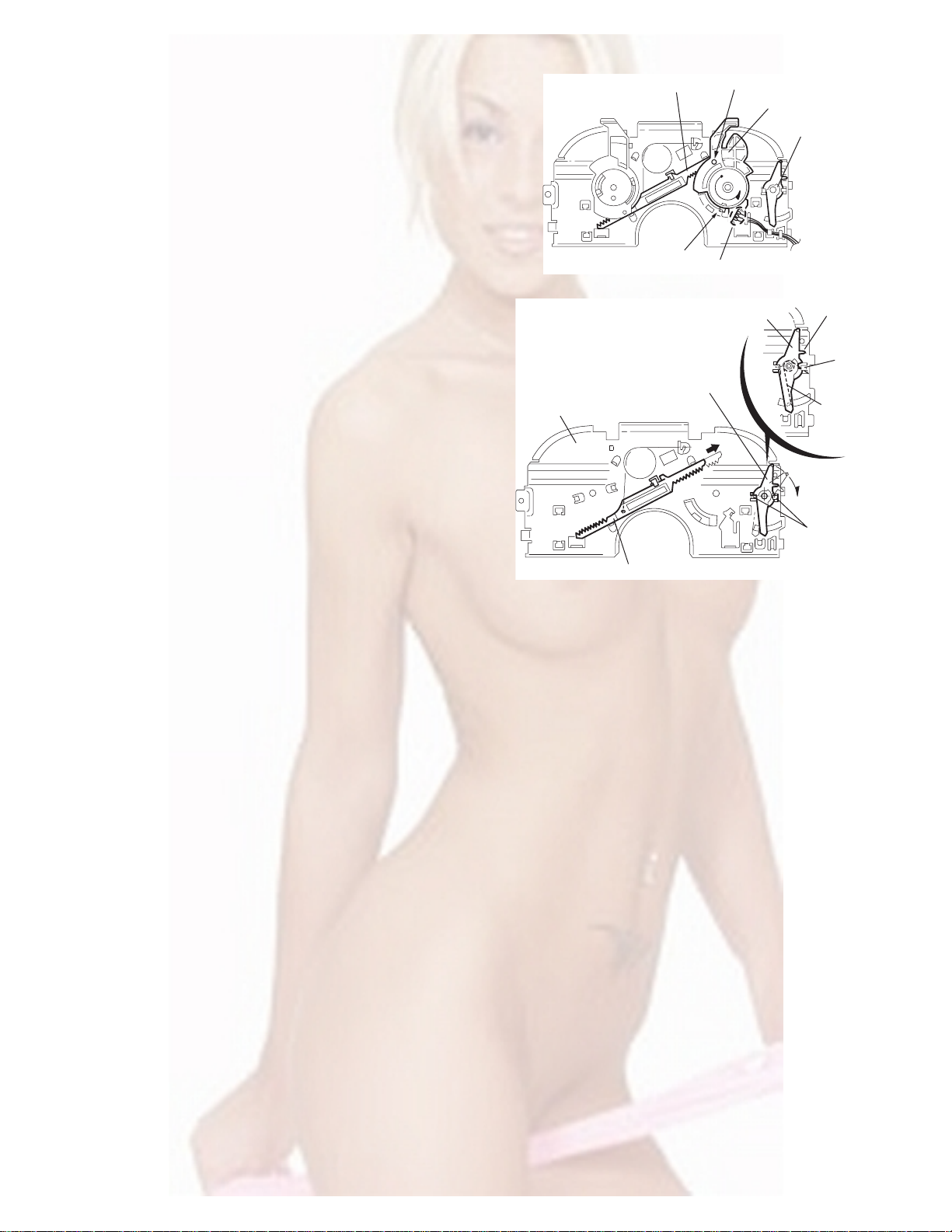
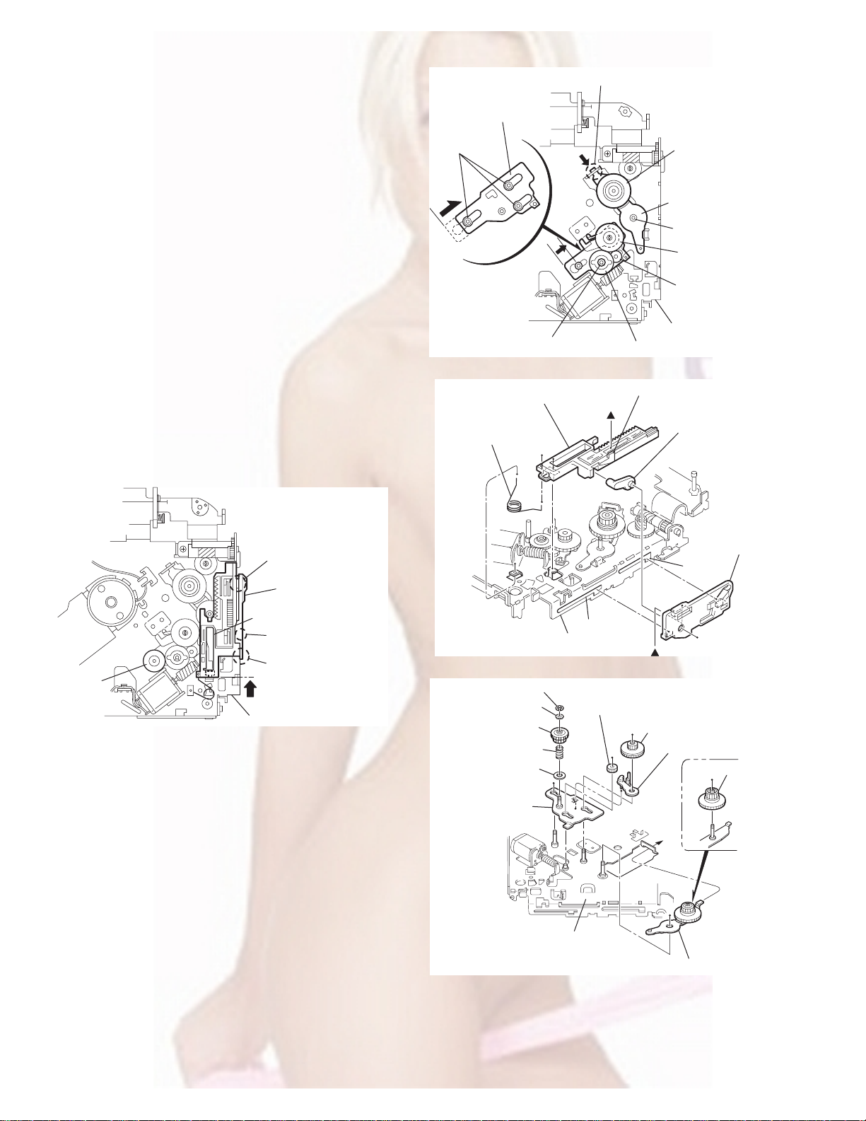
3.2.9 Removing the trigger arm
r
(See Figs.19 and 20)
• Prior to performing the follow ing procedure, remove the top
cover, connector board and clamper unit.
(1) Turn the trigger arm in the direction of the arrow to release
the joint k and pull out upward.
CAUTION:
When reassembling, insert the part m and n of the trigger
arm into the part p and q at the slot of the chassis rivet
assembly respectively and join the joint k at a time.
Chassis rivet assembly
Trigger arm
Chassis rivet
assembly
Joint k
Trigger arm
Fig.19
Part p
Part q
Part m
Part n
3.2.10 Removing the top plate assembly
(See Fig.21)
• Prior to performing the follow ing procedure, remove the top
cover, connector board, chassis unit, and clamper assembly.
(1) Remove the screw H.
(2) Move the top plate assembly in the direction of the arrow to
release the two joints r.
(3) Unsolder the wire marked s if necessary.
H
Fig.20
Top plate assembly
Joints
s
Fig.21
1-16 (No.MA036)
Page 17
3.2.11 Removing the mode sw. / select lock arm
(See Figs.22 and 23)
• Prior to p erforming the following procedure, remove the top
plate assembly.
(1) Bring up the mode sw. to release from the link plate (joint t)
and turn in the direction of the arrow to release the joint u.
(2) Unsolder the wire of the mode sw. marked s if necessary.
(3) Turn the select lock arm in the direction of the arrow to re-
lease the two joints v.
(4) The select lock arm spring comes off the select lock arm at
the same time.
Top plate
Link plate
Joint u
Joint t
s
Fig.22
Select lock arm
Select lock arm
Mode sw.
Select lock arm
Top plate
Hook w
Select lock
arm spring
Link plate
Joints v
Fig.23
(No.MA036)1-17
Page 18
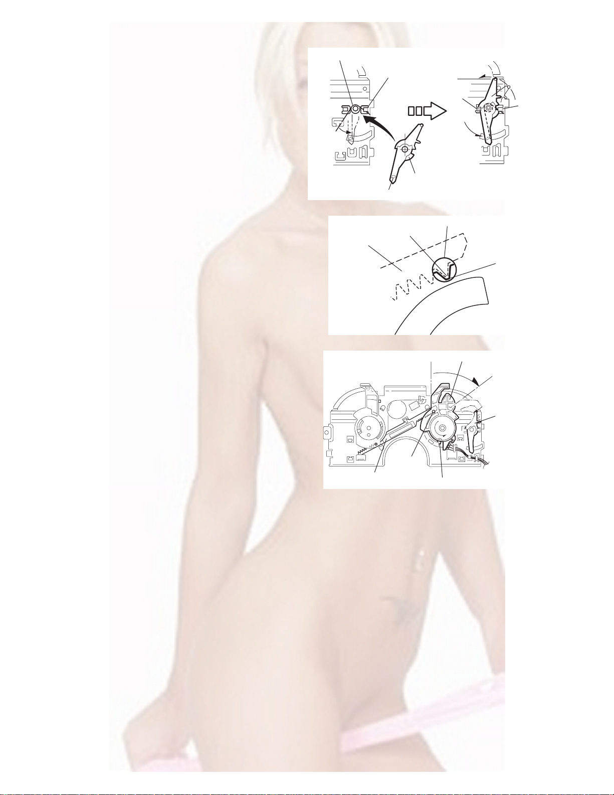
3.2.12 Reassembling the mode sw. / select lock arm
(See Figs.24 to 26)
REFERENCE:
Reverse the above removing procedure.
(1) Reattach the select lock arm spring to the top plate and set
the shorter end of the select lock arm spring to the hook w
on the top plate.
(2) Set the other longer end of the select lock arm spring to the
boss x on the underside of the select lock arm, and join the
select lock arm to the slots (joint v). Turn the select lock
arm as shown in the figure.
(3) Reattach the mode sw. whil e setting the part t to the first
peak of the link plate gear, and join the joint u.
CAUTION:
When reattaching the mode sw., check if the points y and
z are correctly fitted and if each part operates properly.
Select lock arm spring
Hook w
Joint v
Joint v
Select lock arm
Boss x
Fig.24
Joint t
Point y
Link plate
Point z
Link plate
Fig.25
Mode sw.
Select
lock arm
Joint t
Joint u
Fig.26
1-18 (No.MA036)
Page 19
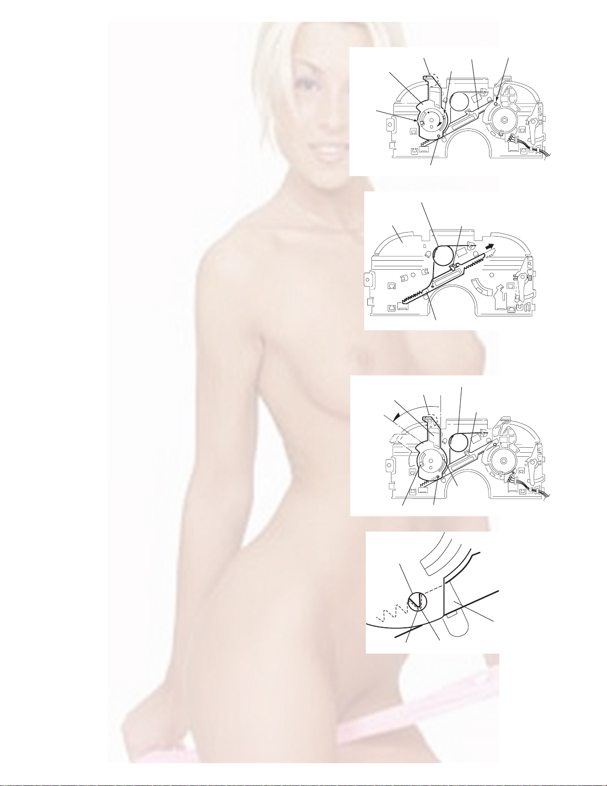
3.2.13 Removing the select arm R / link plate
(See Figs.27 and 28)
• Prior to p erforming the following procedure, remove the top
plate assembly.
(1) Bring up the select arm R to release from the link plate
(joint a') and turn as shown in the figure to release the two
joints b' and joint c'.
(2) Move the link plate in the direction of the arrow to release
the joint d'. Remove the link plate spring at the same time.
REFERENCE:
Before removing the link plate, remove the mode sw..
Select arm R
Joint b'
Link plate spring
Joint c'
Joint a'
Link plate
Joint b'
Fig.27
Joint r
3.2.14 Reattaching the Select arm R / link plate
(See Figs.29 and 30)
REFERENCE:
Reverse the above removing procedure.
(1) Reattach the link plate spring.
(2) Reattach the link plate to the link plate spring wh ile j oining
them at joint d'.
(3) Reattach the joint a' of the select arm R to the first peak of
the link plate while joining the two joints b' with the slots.
Then turn the select arm R as shown in the figure. The top
plate is joined to the joint c'.
CAUTION:
When reattaching the sele ct arm R, check if the points e'
and f' are correctly fitted and if each part operates properly.
Top plate
Select arm R
Joint b'
Joint d'
Link plate
Fig.28
Link plate spring
Joint c'
Joint d'
Joint b'
Joint a'
Fig.29
Joint a'
Point e'
Link plate
Point f'
Fig.30
(No.MA036)1-19
Page 20
3.2.15 Removing the loading roller assembly
(See Figs.31 to 33)
• Prior to performing the following procedure, remove the
clamper assembly and top plate assembly.
(1) Push inward the loading roller a ssembly on the gear side
and detach it upward from the slot of the joint g' of the lock
arm rivet assembly.
(2) Detach the loading roller assembly from the slot of the joint
h' of the lock arm rivet assembly.
Roller guide
spring
Part k'
Loading roller assembly
Loading roller assembly
The roller guide comes off the gear section of the loading
roller assembly.
Remove the roller guide and the HL washer from the shaft
of the loading roller assembly.
(3) Remove the screw J attaching the lock arm rivet assembly.
(4) Push the shaft at the joint i' of the lock arm rivet assembly
inward to release the lock arm rivet assembly from the slot
of the L side plate.
(5) Extend the lock arm rivet assembly outward and relea se
the joint j' from the boss of the chassis rivet assembly. The
roller guide springs on both sides come off at the same
time.
CAUTION:
When reassembling, reattach the left and right roller
guide springs to the lock arm rivet assembly before reattaching the lock arm rivet assembly to the chassis rivet
assembly. Make sure to fit the part k' of the roller guide
spring inside of the roller guide. (Refer to Fig.34.)
Roller guide
HL washer
Loading roller assembly
Roller guide
Chassis rivet assembly
J
Roller guide
spring
Fig.32
Boss
L side plate
Roller guide spring
Joint h'
Roller guide spring
Loading roller assembly
Joint g'
Lock arm rivet assembly
Fig.31
Roller guide spring
Roller guide spring
Lock arm rivet assembly
Lock arm rivet assembly
Joint i'
Part j'
Fig.33
Roller guide
HL washer
Roller shaft assembly
Loading roller
Roller guide spring
Fig.34
1-20 (No.MA036)
Page 21
3.2.16 Removing the loading gear 5, 6 and 7
(See Figs.35 and 36)
• Prior to p erforming the following procedure, remove the top
cover, chassis unit, pickup unit and top plate assembly.
(1) Remove the screw K attaching the lo ading gear bracket.
The loading gear 6 and 7 come off the loading gear bracket.
(2) Pull out the loading gear 5.
K
Loading gear bracket
K
Loading gear 6
Loading gear 5
Loading gear 3
Fig.35
Loading gear bracket
Loading gear 5
Loading gear 6
Loading gear 7
Fig.36
(No.MA036)1-21
Page 22
3.2.17 Removing the gears
(See Figs.37 to 40)
• Prior to performing the follow ing procedure, remove the top
cover, chassis unit, top plate assembly and pickup unit.
• Pull out the loading gear 3. (See Fig .3 5.)
(1) Pull out the feed gear.
(2) Move the loading plate assembly in th e directio n of th e ar-
row to release the L side plate from the two slots m' of the
chassis rivet assembly. (See Fig.37.)
(3) Detach the loading plate assembly upward from the chas-
sis rivet assembly while releasing the joint n'. Remove the
slide hook and loading plate spring from the loading plate
assembly.
(4) Pull out the loading gear 2 and remove the change lock le-
ver.
(5) Remove the E ring and washer attaching the changer gear
2.
(6) The changer gear 2, change gear spring and adjusting
washer come off.
(7) Remove the loading gear 1.
(8) Move the change plate rivet assembly in the direction of the
arrow to release from the three shafts of the chassis rivet
assembly upward. (See Fig.38.)
(9) Detach the loading gear plate rivet assembly from the shaft
of the chassis rivet assembly upward while releasing the
joint p'. (See Figs.38 and 40.)
(10) Pull out the loading gear 4.
Change plate
rivet assembly
Shafts
E ring
Loading plate assembly
Loading plate spring
Joint p'
Loading gear 4
Loading gear plate
rivet assembly
Shaft
Loading gear 2
Loading gear 1
Chassis rivet assembly
Change gear 2
Fig.38
Joint n'
Slide hook
Feed gear
Fig.37
Slot m'
L side plate
Loading plate assembly
Joint n'
Slot m'
Chassis rivet assembly
Chassis rivet assembly
E ring
Washer
Change gear 2
Change gear spring
Adjusting washer
Change plate
rivet assembly
Chassis rivet assembly
L side plate
Slot m'
Slot m'
Fig.39
Loading gear 1
Loading gear 2
Change lock lever
Loading gear 4
1-22 (No.MA036)
Loading gear plate rivet assembly
Fig.40
Page 23
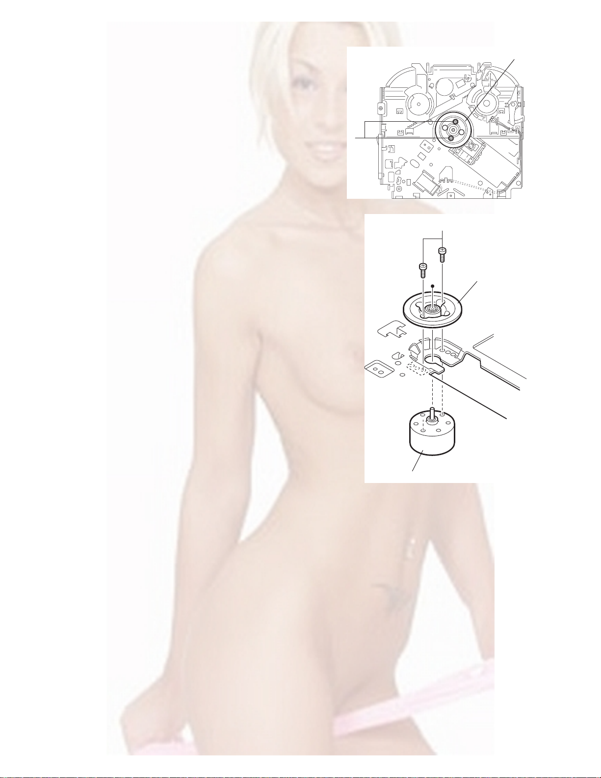
3.2.18 Removing the turn table / spindle motor
(See Figs.41 and 42)
• Prior to p erforming the following procedure, remove the top
cover, connector board, chassis unit and clamper assembly.
(1) Remove the two screws L attaching the spindle motor as-
sembly through the slot of the turn table on top of the body.
(2) Unsolder the wire on the connector board if necessary.
Turn table
L
Fig.41
L
Turn table
Spindle motor
Fig.42
(No.MA036)1-23
Page 24
SECTION 4
ADJUSTMENT
4.1 Adjustment method
Test instruments required for adjustment
(1) Digital oscilloscope (100MHz)
(2) AM Standard signal generator
(3) FM Standard signal generator
(4) Stereo modulator
(5) Electric voltmeter
(6) Digital tester
(7) Tracking offset meter
(8) Test Disc JVC :CTS-1000
(9) Extension cable for check
EXTSH002-22P × 1
Standard volume position
Balance and Bass &Treble volume : lndication"0"
Loudness : OFF
How to connect the extension cable for adjusting
Caution:
Be sure to attach the heat sink and rear bracket onto the power amplifier IC and regulator IC respectively, before supply the power.
If voltage is applied without attaching these parts, the power amplifier IC and regulator IC will be destroyed by heat.
Standard measuring conditions
Power supply voltage DC14.4V(10.5 to 16V)
Load impedance 20KΩ(2 Speakers connection)
Output Level Line out 2.0V (Vol. MAX)
Dummy load
Exclusive dummy load should be used for AM,and FM. For FM
dummy load,there is a loss of 6dB between SSG output and
antenna input.The loss of 6dB need not be considered since
direct reading of figures are applied in this working standard.
1-24 (No.MA036)
Heat sink
Extension cable
EXTSH002-22P
Rear bracket
Page 25

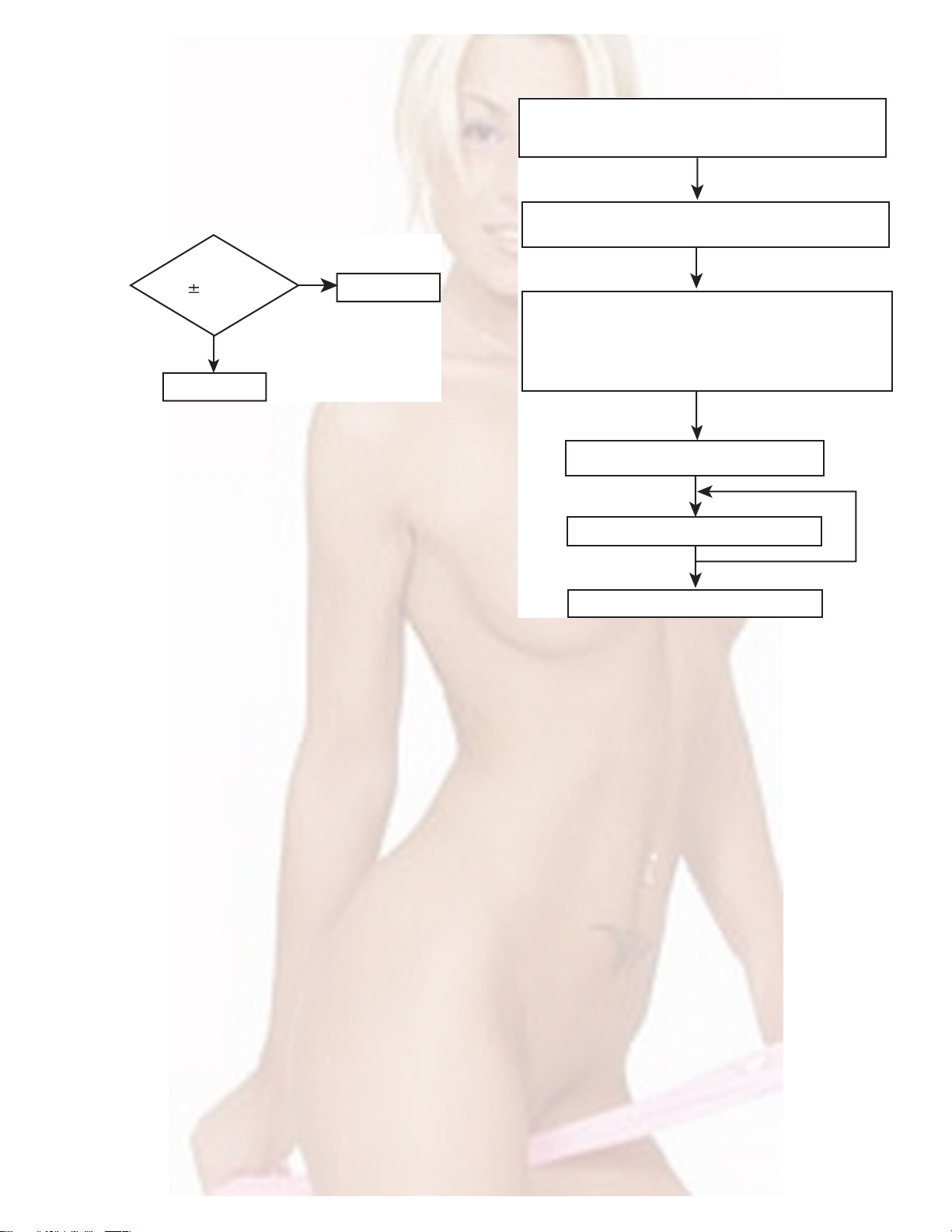
5.1 Feed section
SECTION 5
TROUBLE SHOOTING
Is the voltage output at
IC541 pin 40 5v or 0V
YES
Is 4V present at both
sides of the feed motor?
YES
Check the feed motor.
5.2 Focus section
5.3 Spindle section
NO
Is the wiring for IC541
pin 40 correct?
NO
Is 6V or 2V present at
IC501 pins 4 and 5?
Check IC501.
When the lens is
moving:
Does the S-search
waveform appear at
IC501 pins 8 and 9?
NO
NO
YES
4V
YES
YES
NO
Is 5V present at IC501
pins 3,12 and 21?
Check the vicinity of
IC541.
Check the feed motor
connection wiring.
Check the circuits in
the vicinity of IC501
pins 8 and 9.
Check the pickup and
its connections.
NO
Check CD 8V.
YES
YES
Is the disk rotated?
YES
Does the RF signal
appear at IC521 pin 19?
YES
Is the RF waveform
at IC521 pin 19
distorted?
YES
Proceed to the Tracking
section
5.4 Tracking section
When the disc is rotated
at first:
Is the tracking error
signal output at
IC521 pin 11?
NO
Is 4V present between
IC501 pins 6 and 7?
Check the spindle motor
and its wiring.
NO
Check the circuits in
the vicinity of IC521
pin 19 or the pickup.
NO
NO
Approx. 1.2V
NO
YES
Check the circuits in
the vicinity of IC501
pins 2 to 11.
Is 4V present at IC541
pin 41?
YES
Check the vicinity of
IC501
NO
Check the pickup and
its connections.
NO
Check IC541.
YES
Check IC541.
(No.MA036)1-25
Page 26

5.5 Signal processing section
Is the sound output from
both channels (L, R)?
Normal
YES
No sound from either
channel.
YES
Is 9V present at IC161 pin
31?
YES
NONO
Compare the L-ch and
R-ch to locate the
defective point.
NO
Check the vicinity of the
IC901 audio power
supply.
Is the audio signal
(including sampling output
components) output to
IC581 pins 1 and 7 during
playback?
YES
Is the audio signal output
at IC161 pins 3 and 30
during playback?
YES
Check the muting circuit.
NO
NO
Check IC581 and its
peripheral circuits.
Check IC161 and its
peripheral circuits.
1-26 (No.MA036)
Page 27
5.6 Maintenance of laser pickup
(1) Cleaning the pick up lens
Before you replace the pick up, please try to clean the lens
with a alcohol soaked cotton swab.
(2) Life of the laser diode
When the life of the laser diode has expired, the following
symptoms will appear.
• The level of RF output (EFM output: amplitude of eye
pattern) will be low.
5.7 Replacement of laser pickup
Turn off the power switch and,disconnect the
power cord from the ac outlet.
Replace the pickup with a normal one.(Refer
to "Pickup Removal" on the previous page)
Is RF output
1.0 0.35Vp-p?
YES
O.K
(3) Semi-fixed resistor on the APC PC board
The semi-fixed resistor on the APC printed circuit board
which is attached to the pickup is used to adjust the laser
power.Since this adjustment should be performed to match
the characteristics of the whole optical block, do not touch
the semi-fixed resistor.
If the laser power is lower than the specified value, the laser diode is almost worn out, and the laser pickup should
be replaced. If the semi-fixed resistor is adjusted while the
pickup is functioning normally, the laser pickup may be
damaged due to excessive current.
NO
Replace it.
Plug the power cord in,and turn the power on.
At this time,check that the laser emits for
about 3seconds and the objective lens moves
up and down.
Note: Do not observe the laser beam directly.
Play a disc.
Check the eye-pattern at TP1.
Finish.
(No.MA036)1-27
Page 28
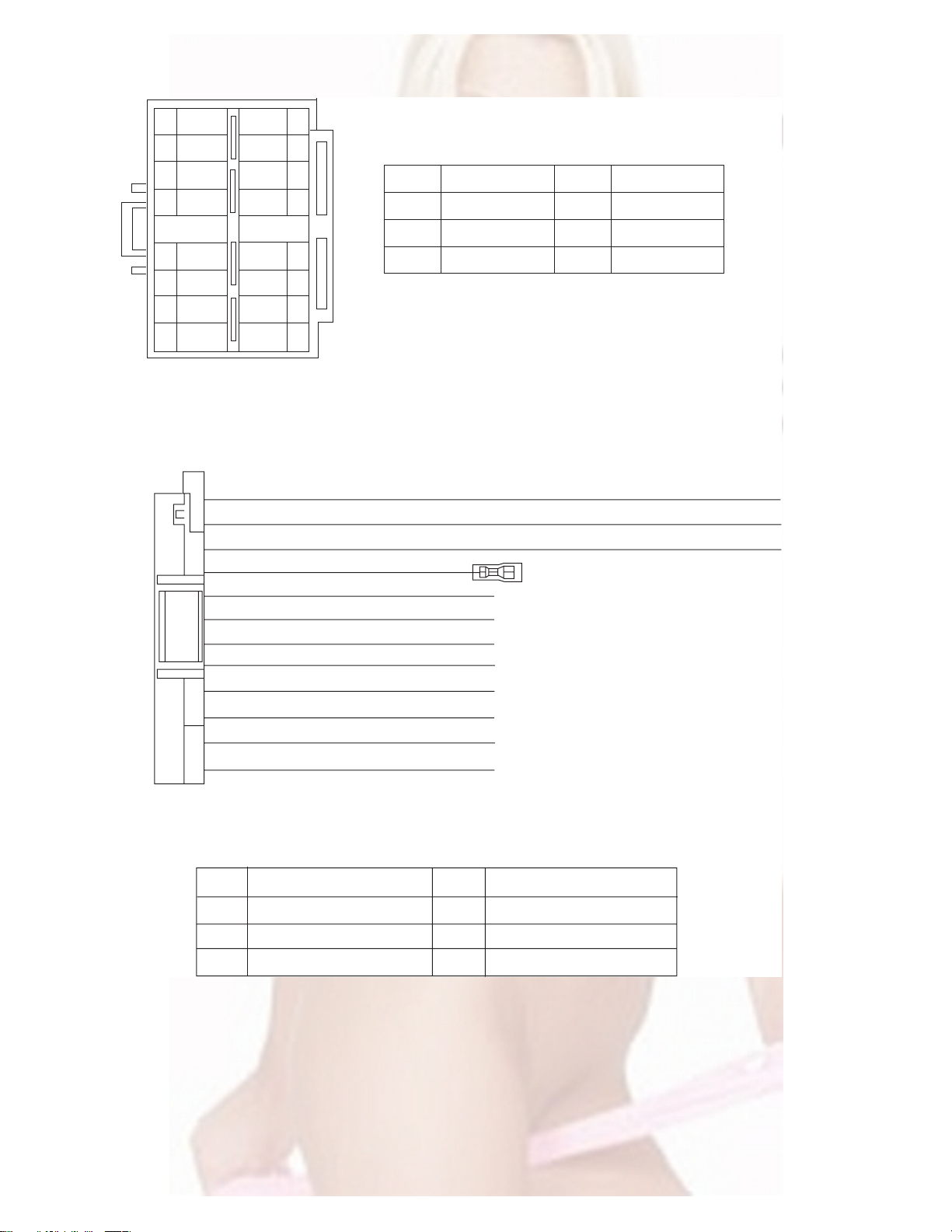
5.8 16 pin cord diagram
8
7
6
BL/WH
5
4
3
2
1
BK
RD
NC
WH
GN
VI
GY
WH/BK
GN/BK
GY/BK
16 YL
8 BK
7 RD
5 BL/WH REMOTE
4 WH
12 WH/BK
3 GN
11 GN/BK RL-
2 VI RR+
10 VI/BK
1 GY FR+
YL
NC
NC
NC
VI/BK
16
15
14
13
12
11
10
9
MEMORY
GND
ACC
FL+
FL-
RL+
RR-
BK
RD
BL
WH
Black
Red
Blue
White
GN
VI
GY
YL
Green
Violet
Gray
Yellow
1-28 (No.MA036)
9 GY/BK
RR
FR
FL
RL
Rear Right
Front Right
Front Left
Rear Left
FR-
REMOTE
ACC
MEMORY
GND
Remote
ACC Line
Memory Backup Battery
Ground
Page 29

VICTOR COMPANY OF JAPAN, LIMITED
AV & MULTIMEDIA COMPANY MOBILE ENTERTAINMENT CATEGORY 10-1,1chome,Ohwatari-machi,Maebashi-city,371-8543,Japan
(No.MA036)
Printed in Japan
WPC
Page 30

CD RECEIVER KD-AR300/KD-G300
ENGLISH
RECEPTOR CON CD KD-AR300/KD-G300
RECEPTEUR CD KD-AR300/KD-G300
KD-AR300
S
KD-G300
S
• This unit is equipped with the display demonstration. To cancel it, see page 8.
• Esta unidad está equipada con demostración en la pantalla. Para cancelarla, consulte la página 8.
• Cet appareil est équipé d’une fonction de démonstration des affichages. Pour l’annuler, référezvous à la page 8.
For installation and connections, refer to the separate manual.
Para la instalación y las conexiones, refiérase al manual separado.
Pour l’installation et les raccordements, se référer au manuel séparé.
For customer Use:
Enter below the Model No. and
Serial No. which are located on
INSTRUCTIONS
MANUAL DE INSTRUCCIONES
MANUEL D’INSTRUCTIONS
the top or bottom of the
cabinet. Retain this information
for future reference.
Model No.
Serial No.
GET0211-001A
ESPAÑOL
FRANÇAIS
[J]
Page 31
INFORMATION (For U.S.A.)
This equipment has been tested and found to comply with the limits for a Class B digital device,
pursuant to Part 15 of the FCC Rules. These limits are designed to provide reasonable protection
against harmful interference in a residential installation. This equipment generates, uses, and can
radiate radio frequency energy and, if not installed and used in accordance with the instructions,
ENGLISH
may cause harmful interference to radio communications. However, there is no guarantee that
interference will not occur in a particular installation. If this equipment does cause harmful
interference to radio or television reception, which can be determined by turning the equipment off
and on, the user is encouraged to try to correct the interference by one or more of the following
measures:
– Reorient or relocate the receiving antenna.
– Increase the separation between the equipment and receiver.
– Connect the equipment into an outlet on a circuit different from that to which the receiver is
connected.
– Consult the dealer or an experienced radio/TV technician for help.
IMPORTANT FOR LASER PRODUCTS
1. CLASS 1 LASER PRODUCT
2. CAUTION: Do not open the top cover. There are no user serviceable parts inside the unit; leave all
servicing to qualified service personnel.
3. CAUTION: Visible and invisible laser radiation when open and interlock failed or defeated. Avoid
direct exposure to beam.
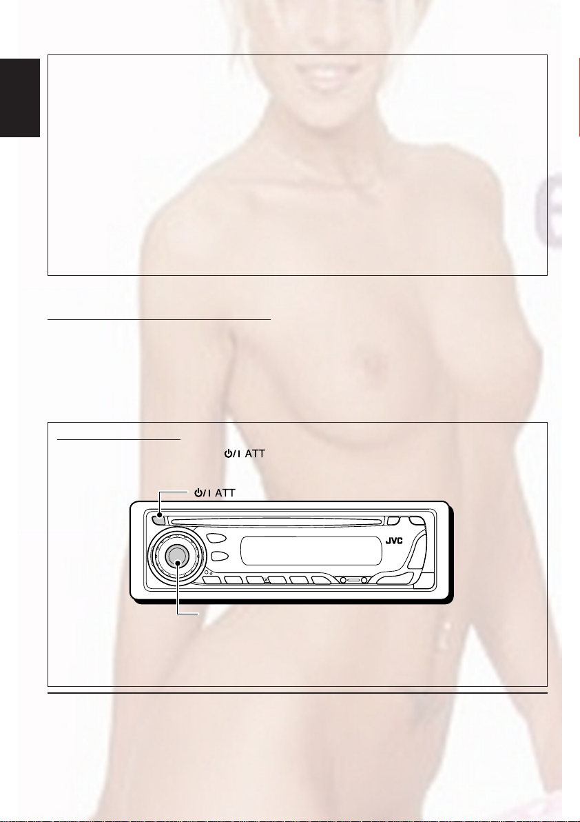
How to reset your unit
While holding SEL (select), press (standby/on attenuator) for more than 2 seconds.
This will reset the built-in microcomputer.
(standby/on attenuator)
SEL (select)
Notes:
• Your preset adjustments—such as preset channels or sound adjustments—will also be erased.
• If a disc is in the unit, it will eject when you reset the unit. Be careful not to drop the disc.
BEFORE USE
*For safety....
• Do not raise the volume level too much, as this will
block outside sounds, making driving dangerous.
• Stop the car before performing any complicated
operations.
*Temperature inside the car....
If you have parked the car for a long time in hot or
cold weather, wait until the temperature in the car
becomes normal before operating the unit.
2
Page 32

Thank you for purchasing a JVC product. Please read all instructions carefully before operation,
to ensure your complete understanding and to obtain the best possible performance from the unit.
CONTENTS
How to reset your unit ............................... 2
How to use the MODE button ................... 3
LOCATION OF THE BUTTONS ............ 4
Control panel ............................................. 4
Remote controller ...................................... 5
Preparing the remote controller ................ 6
BASIC OPERATIONS ....................... 7
Turning on the power ................................ 7
Canceling the display demonstration ........ 8
Setting the clock ........................................ 9
RADIO OPERATIONS ...................... 10
Listening to the radio ................................. 10
Storing stations in memory ....................... 11
Tuning in to a preset station ...................... 12
CD OPERATIONS ........................... 13
Playing a CD ............................................. 13
Locating a track or a particular portion
on a CD .................................................. 14
Selecting CD playback modes .................. 15
Playing a CD Text ...................................... 16
Prohibiting disc ejection ............................ 16
MP3 INTRODUCTION ...................... 17
What is MP3? ............................................ 17
How are MP3 files recorded and
played back? .......................................... 17
MP3 OPERATIONS ......................... 18
Playing an MP3 disc ................................. 18
Locating a file or a particular portion on
an MP3 disc ............................................ 19
Selecting MP3 playback modes ................ 21
SOUND ADJUSTMENTS ................... 22
Selecting preset sound modes
(C-EQ: custom equalizer) ....................... 22
Adjusting the sound .................................. 23
OTHER MAIN FUNCTIONS ................ 24
Changing the general settings (PSM) ....... 24
Detaching the control panel ...................... 27
CD CHANGER OPERATIONS
(only for KD-AR300) ................................ 28
Playing discs ............................................. 28
Selecting the playback modes .................. 31
EXTERNAL COMPONENT OPERATIONS
(only for KD-AR300) .......................... 32
Playing an external component ................. 32
TROUBLESHOOTING ...................... 33
MAINTENANCE ............................. 36
Handling discs ........................................... 36
SPECIFICATIONS........................... 37
ENGLISH
How to use the MODE button
If you press MODE, the unit goes into functions mode, then the number buttons and 5/∞ buttons
work as different function buttons.
Ex.: When number button 2 works as MO (monaural) button.
Time countdown indicator
To use these buttons for original functions again after pressing MODE, wait for 5 seconds
without pressing any of these buttons until the functions mode is cleared.
• Pressing MODE again also clears the functions mode.
3
Page 33

Control panel
Display window
ENGLISH
LOCATION OF THE BUTTONS
KD-AR300
1 (standby/on attenuator) button
2 SEL (select) button
3 FM/AM button
4 For KD-AR300:
• CD CD-CH (CD changer) button
For KD-G300:
• CD button
5 Loading slot
6 Display window
7 0 (eject) button
8 Remote sensor
9 EQ (equalizer) button
p 5 (up) button
+10 button
q Control dial
w Number buttons
e MO (monaural) button
r SSM (Strong-station Sequential Memory)
button
t RPT (repeat) button
y RND (random) button
u MODE button
i DISP (display) button
o 4/¢ buttons
; (control panel release) button
4
KD-G300
a ∞ (down) button
–10 button
Display window
s Tuner reception indicators—MO (monaural),
ST (stereo)
d MP3 indicator
f CH (CD changer) indicator
• Only for KD-AR300: Lights up only when
connecting to a CD changer.
g CD indicator
h Playback mode/item indicators—RND (random),
(disc), (folder), RPT (repeat)
j LOUD (loudness) indicator
k EQ (equalizer) indicator
l Sound mode (C-EQ: custom equalizer)
indicators—ROCK, CLASSIC, POPS,
HIP HOP, JAZZ, USER
/ Disc information indicators—TAG (ID3 Tag),
(folder), (track/file)
z Main display
x Source display
Volume level indicator
c Tr (track) indicator
Page 34

Remote controller
S
3 • Selects the preset stations while listening to
the radio.
Each time you press the button, the preset
station number increases, and the selected
station is tuned in.
• Skips to the first file of the previous folder
while listening to an MP3 disc.
Each time you press the button, you can
move to the previous folder and start playing
the first file.
• For KD-AR300:
While playing an MP3 disc on an MP3compatible CD changer;
– Skips to the previous disc if pressed
briefly.
– Skips to the previous folder if pressed and
held.
Note:
While playing a CD on a CD changer, this
always skips to the previous disc.
4 Selects the sound mode (C-EQ: custom
equalizer).
Each time you press the button, the sound
mode (C-EQ) changes.
ENGLISH
1 • Turns on the unit if pressed when the unit is
turned off.
• Turns off the unit if pressed and held until
“SEE YOU” appears on the display.
• Drops the volume level in a moment if
pressed briefly.
Press again to resume the volume.
2 • Searches for stations while listening to the
radio.
• Fast-forwards or reverses the track/file if
pressed and held while listening to a disc.
• Skips to the beginning of the next track/file
or goes back to the beginning of the current
(or previous) tracks/files if pressed briefly
while listening to a disc.
5 • Selects the band while listening to the radio.
Each time you press the button, the band
changes.
• Skips to the first file of the next folder while
listening to an MP3 disc.
Each time you press the button, you can
move to the next folder and start playing the
first file.
• For KD-AR300:
While playing an MP3 disc on an MP3compatible CD changer;
– Skips to the next disc if pressed briefly.
– Skips to the next folder if pressed and
held.
Note:
While playing a CD on a CD changer, this
always skips to the next disc.
6 Selects the source.
Each time you press the button, the source
changes.
7 Functions the same as the control dial on the
main unit.
Note:
These buttons do not function for the
preferred setting mode (PSM) adjustment.
5
Page 35

Preparing the remote controller
Before using the remote controller:
• Aim the remote controller directly at the remote
sensor on the main unit. Make sure there is no
ENGLISH
obstacle in between.
Remote sensor
• Do not expose the remote sensor to strong
light (direct sunlight or artificial lighting).
Installing the battery
When the controllable range or effectiveness of
the remote controller decreases, replace the
battery.
1. Remove the battery holder.
1) Push out the battery holder in the direction
indicated by the arrow using a ball-point
pen or a similar tool.
2) Remove the battery holder.
(back side)
2. Place the battery.
Slide the battery into the holder with the +
side facing upwards so that the battery is
fixed in the holder.
Lithium coin
battery (product
number: CR2025)
3. Return the battery holder.
Insert again the battery holder by pushing it
until you hear a clicking sound.
(back side)
WARNING:
• Store the battery in a place where children
cannot reach.
If a child accidentally swallows the battery,
consult a doctor immediately.
• Do not recharge, short, disassemble, or heat the
battery or dispose of it in a fire.
Doing any of these things may cause the battery
to give off heat, crack, or start a fire.
• Do not leave the battery with other metallic
materials.
Doing this may cause the battery to give off
heat, crack, or start a fire.
• When throwing away or saving the battery,
wrap it in tape and insulate; otherwise, the
battery may start to give off heat, crack, or start
a fire.
• Do not poke the battery with tweezers or similar
tools.
Doing this may cause the battery to give off
heat, crack, or start a fire.
CAUTION:
DO NOT leave the remote controller in a place
(such as dashboards) exposed to direct sunlight
for a long time. Otherwise, it may be damaged.
6
Page 36

BASIC OPERATIONS
ENGLISH
1
3 2
Turning on the power
1
Turn on the power.
Note on One-Touch Operation:
When you select a source in step 2 below, the
power automatically comes on. You do not have
to press this button to turn on the power.
2
Select the source.
(For KD-AR300)
To operate the tuner (FM or AM),
see pages 10 – 12.
To play a CD,
see pages 13 – 16.
To play an MP3 disc,
see pages 18 – 21.
To operate the CD changer (only for
KD-AR300), see pages 28 – 31.
To operate the external component (LINE IN
or SIRIUS—only for KD-AR300), see
page 32.
3
Adjust the volume.
(For KD-G300)
To increase the volume
To decrease the volume
Volume level appears.
Volume level indicator
4
Adjust the sound as you want. (See
pages 22 and 23.)
To drop the volume in a moment
Press briefly while listening to any
source. “ATT” starts flashing on the display, and
the volume level will drop in a moment.
To resume the previous volume level, press the
button briefly again.
• If you turn the control dial, you can also restore
the sound.
To turn off the power
Press and hold for more than one
second.
“SEE YOU” appears, then the unit turns off.
• If you turn off the power while listening to a
disc, disc play will start from where playback
has been stopped previously, next time you
turn on the power.
CAUTION on Volume Setting:
Discs produce very little noise compared with
other sources. If the volume level is adjusted for
the tuner, for example, the speakers may be
damaged by the sudden increase in the output
level. Therefore, lower the volume before playing a
disc and adjust it as required during playback.
7
Page 37

ENGLISH
Canceling the display
demonstration
When shipped from the factory, display
demonstration has been activated, and starts
automatically when no operations are done for
about 20 seconds.
• It is recommended to cancel the display
demonstration before you use the unit for the
first time.
To cancel the display demonstration, follow
the procedure below:
1
Press and hold SEL (select) for more
than 2 seconds so that one of the
PSM items appears on the display.
(PSM: see page 25.)
2
Select “DEMO” if not shown on the
display.
3
Select “DEMO OFF.”
DEMO OFF
4
Finish the setting.
To activate the display demonstration, repeat
the same procedure and select “DEMO ON” in
step 3.
DEMO ON
8
Page 38

ENGLISH
Frequency
Clock
Setting the clock
1
Press and hold SEL (select) for more
than 2 seconds so that one of the
PSM items appears on the display.
(PSM: see page 25.)
2
Set the hour.
1 Select “CLOCK H” (hour) if not shown on
the display.
2 Adjust the hour.
12
3
Set the minute.
1 Select “CLOCK M” (minute).
2 Adjust the minute.
12
To check the current clock time or change the
display mode
Press DISP (display) repeatedly.
Each time you press the button,
the display changes as follows:
• During tuner operation:
• During disc operation:
Elapsed
playing time
Track title
Notes:
• While playing an audio CD, “NO NAME” appears
for the disc title/performer and the track title.
• For indication change while playing a CD Text or
an MP3 disc, see also pages 16 and 19.
• For KD-AR300:
During external component operation:
LINE IN
• For KD-AR300:
During SIRIUS operation:
SIRIUS
Clock
Disc title /
performer
Clock
Clock
4
Finish the setting.
• During power off:
The power turns on and the clock time is
shown for 5 seconds, then the power turns off.
9
Page 39

ENGLISH
RADIO OPERATIONS
Listening to the radio
You can use either automatic searching or manual
searching to tune in to a particular station.
Searching for a station automatically:
Auto search
1
Select the band (FM1 – 3, AM).
Each time you press the
button, the band changes as
follows:
FM1 FM2 FM3 AM
Lights up when receiving an FM stereo
broadcast with sufficient signal strength.
Selected band appears.
Note:
This receiver has three FM bands (FM1, FM2,
FM3). You can use any one of them to listen to
an FM broadcast.
2
Start searching for a station.
To search for stations of
higher frequencies
To stop searching before a station is received,
press the same button you have pressed for
searching.
Searching for a station manually:
Manual search
1
Select the band (FM1 – 3, AM).
Each time you press the
button, the band changes as
follows:
FM1 FM2 FM3 AM
Note:
This receiver has three FM bands (FM1, FM2,
FM3). You can use any one of them to listen to
an FM broadcast.
2
Press and hold ¢ or 4
until “M” (manual) starts flashing on
the display.
10
To search for stations of lower frequencies
When a station is received, searching stops.
Page 40

3
Tune in to a station you want while
“M” (manual) is still flashing.
To tune into stations of
higher frequencies
To tune into stations of lower frequencies
• If you release your finger from the button,
the manual mode will automatically turns
off after 5 seconds.
• If you hold down the button, the frequency
keeps changing (in 200 kHz intervals for
FM and 10 kHz for AM) until you release
the button.
When an FM stereo broadcast is hard to
receive:
1 Press MODE to enter the
functions mode while listening
to an FM stereo broadcast.
2 Press MO (monaural), while
“MODE” is still flashing on the
display, so that “MONO”
appears on the display.
Each time you press the button,
the monaural mode turns on
and off alternately.
Storing stations in memory
You can use one of the following two methods to
store broadcasting stations in memory.
• Automatic preset of FM stations: SSM (Strongstation Sequential Memory)
• Manual preset of both FM and AM stations
FM station automatic preset: SSM
You can preset 6 local FM stations in each FM
band (FM1, FM2, and FM3).
1
Select the FM band (FM1 – 3) you
want to store FM stations into.
Each time you press the
button, the band changes as
follows:
FM1 FM2 FM3 AM
2
Press MODE to enter the functions
mode.
3
Press and hold SSM for about
2 seconds.
ENGLISH
MO (monaural) indicator
When the MO indicator is lit on the display, the
sound you hear becomes monaural but the
reception will be improved.
“SSM” flashes, then disappears when
automatic preset is over.
Local FM stations with the strongest signals are
searched and stored automatically in the band
number you have selected (FM1, FM2, or FM3).
These stations are preset in the number buttons
—No.1 (lowest frequency) to No.6 (highest
frequency).
When automatic preset is over, the station stored
in number button 1 will be automatically tuned in.
11
Page 41

Manual preset
You can preset up to 6 stations in each band
(FM1, FM2, FM3, and AM) manually.
ENGLISH
Ex.: Storing FM station of 92.5 MHz into the
preset number 1 of the FM1 band.
1
Select the band (FM1 – 3, AM) you
want to store stations into (in this
example, FM1).
Each time you press the
button, the band changes as
follows:
FM1 FM2 FM3 AM
4
Repeat the above procedure to store
other stations into other preset
numbers.
Notes:
• A previously preset station is erased when a new
station is stored in the same preset number.
• Preset stations are erased when the power supply to
the memory circuit is interrupted (for example,
during battery replacement). If this occurs, preset
the stations again.
Tuning in to a preset station
2
Tune in to a station (in this example,
of 92.5 MHz).
To tune into stations of
higher frequencies
To tune into stations of lower frequencies
3
Press and hold the number button
(in this example, 1) for more than
2 seconds.
Preset number flashes for a while.
You can easily tune in to a preset station.
Remember that you must store stations first. If
you have not stored them yet, see “Storing
stations in memory” on pages 11 and 12.
1
Select the band (FM1 – 3, AM).
Each time you press the
button, the band changes as
follows:
FM1 FM2 FM3 AM
2
Select the number (1 – 6) for the
preset station you want.
Note:
You can also use the 5 (up) or ∞ (down) button on
the unit to select the next or previous preset stations.
Each time you press the 5 (up) or ∞ (down) button,
the next or previous preset station is tuned in.
12
Page 42

CD OPERATIONS
ENGLISH
Refer to “MP3 OPERATIONS” on pages 18 to 21
for operating MP3 discs.
Playing a CD
Insert a CD into the loading slot.
The unit turns on, draws
the CD and starts
playback automatically.
Note on One-Touch Operation:
When a CD is already in the loading slot, pressing
CD CD-CH (for KD-AR300) or CD (for KD-G300)
turns on the unit and starts playback automatically.
CD indicator
Current source indication
Total playing time
of the inserted disc
Total track number
of the inserted disc
Notes:
• When a CD is inserted upside down, “EJECT”
appears on the display and the CD automatically
ejects.
• If there is no CD in the loading slot, you cannot
select CD as the source. “NO DISC” appears on
the display.
• If the current disc is a CD Text, disc title/performer
and then track title will automatically appear.
To stop play and eject the CD
Press 0.
CD play stops and the CD automatically ejects
from the loading slot. The source changes to the
previously selected source.
• If you change the source, CD play also stops
(without ejecting the CD).
Next time you select “CD” as the source, CD
play starts from where playback has been
stopped previously.
Notes:
• If the ejected disc is not removed for about
15 seconds, the disc is automatically inserted again
into the loading slot to protect it from dust.
(Disc play will not start this time.)
• You can eject the disc even when the unit is turned
off.
Elapsed playing time Current track
number
All tracks will be played repeatedly until you stop
playback.
13
Page 43

Locating a track or a
particular portion on a CD
To fast-forward or reverse the track
ENGLISH
Press and hold ¢ , while
playing a CD, to fast-forward the
track.
To go to a track quickly (+10 and –10 buttons)
1 Press MODE to enter the functions mode
while playing a CD.
2 Press +10 or –10.
Press and hold 4, while playing a CD, to
reverse the track.
To go to the next or previous tracks
Press ¢ briefly, while
playing a CD, to go ahead to the
beginning of the next track.
Each time you press the button
consecutively, the beginning of
the next tracks is located and
played back.
Press 4 briefly, while playing a CD, to go
back to the beginning of the current track.
Each time you press the button consecutively,
the beginning of the previous tracks is located
and played back.
To go to a particular track directly
Press the number button corresponding to the
track number to start its playback.
To skip 10 tracks* forwards to
the last track
To skip 10 tracks* backwards
to the first track
* First time you press +10 or –10 button, the
track skips to the nearest higher or lower
track with a track number of multiple ten (ex.
10th, 20th, 30th).
Then each time you press the button, you can
skip 10 tracks (see “How to use the +10 and
–10 buttons” below).
• After the last track, the first track will be
selected, and vice versa.
How to use the +10 and –10 buttons
• Ex. 1: To select track number 32 while
playing track number 6
(Three times)
Track 6 \ 10 \ 20 \ 30 \ 31 \ 32
• Ex. 2: To select track number 8 while playing
track number 36
(Twice)
• To select a track number from 1 – 6:
Press 1 (7) – 6 (12) briefly.
• To select a track number from 7 – 12:
Press and hold 1 (7) – 6 (12) for more than one
second.
14
(Three times) (Twice)
Track 36 \ 30 \ 20 \ 10 \ 9 \ 8
Page 44

Selecting CD playback modes
To play back tracks at random
(Disc Random Play)
You can play back all tracks on the CD at random.
1 Press MODE to enter the
functions mode while playing a
CD.
2 Press RND (random), while
“MODE” is still flashing on the
display, so that “DISC RND”
appears on the display.
Each time you press the button,
disc random play mode turns on
and off alternately.
RND and (disc) indicators
When disc random play is turned on, the RND
and indicators light up on the display. A track
randomly selected starts playing.
To play back tracks repeatedly
(Track Repeat Play)
You can play back the current track repeatedly.
1 Press MODE to enter the
functions mode while playing a
CD.
2 Press RPT (repeat), while
“MODE” is still flashing on the
display, so that “TRK RPT”
appears on the display.
Each time you press the button,
track repeat play mode turns on
and off alternately.
RPT indicator
When track repeat play is turned on, the RPT
indicator lights up on the display. The current
track starts playing repeatedly.
ENGLISH
15
Page 45
Playing a CD Text
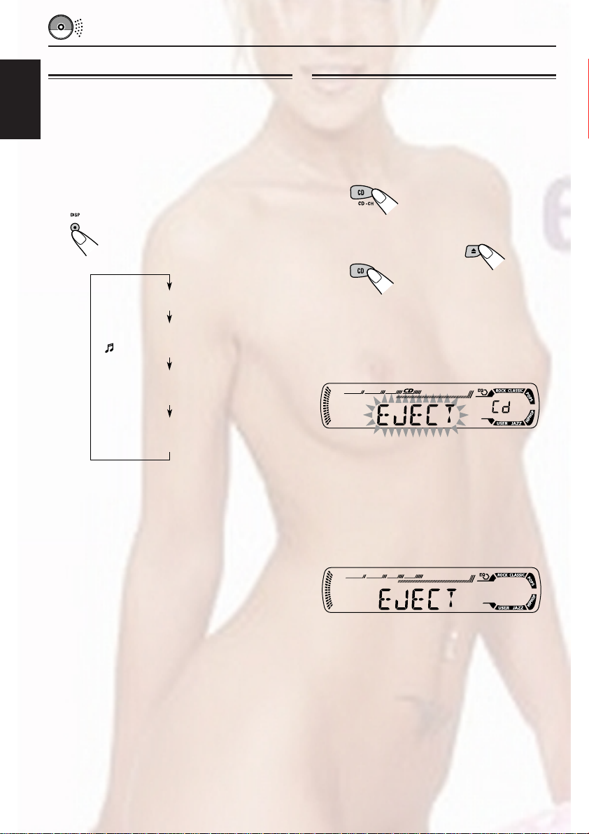
Prohibiting disc ejection
In a CD Text, some information about the disc (its
disc title, performer, and track title) is recorded.
This CD Text information will be shown
ENGLISH
automatically when you play a CD Text.
To change the CD Text information
manually, select text display mode while
playing a CD Text.
Press DISP (display) repeatedly.
Each time you press the button,
the display changes as follows:
Disc title / performer
Track title
( lights up on the display)
Elapsed playing time and
Current track number
Clock and
Current track number
Notes:
• The display shows up to 8 characters at one time
and scrolls if there are more than 8 characters.
See also “To select the scroll mode—SCROLL” on
page 25.
Some characters or symbols will not be shown (and
will be blanked) on the display.
(Ex. “ABCå!d#” ]“ABCA D ”)
• When you press DISP (display) while playing an
audio CD, “NO NAME” appears for the disc title/
performer and the track title.
• When track title is shown, the Tr indicator and
current track number also appear on the right side
of the display.
You can prohibit disc ejection and can lock a disc
in the loading slot.
While pressing CD CD-CH (for
KD-AR300) or CD (for KD-G300), press
and hold 0 for more than 2 seconds.
(For KD-AR300)
or
(For KD-G300)
“EJECT” flashes on the display for about
5 seconds, and the disc is locked and cannot be
ejected.
To cancel the prohibition and unlock the
disc
While pressing CD CD-CH (for KD-AR300) or
CD (for KD-G300), press and hold 0 again for
more than 2 seconds.
“EJECT” appears on the display, and the disc
ejects from the loading slot.
16
Page 46

MP3 INTRODUCTION
What is MP3?
MP3 is an abbreviation of Motion Picture Experts
Group (or MPEG) Audio Layer 3. MP3 is simply a
file format with a data compression ratio of 1:10
(128 Kbps*).
* Bit rate is the average number of bits that one
second of audio data will consume. The unit used is
Kbps. To get a better audio quality, choose a higher
bit rate. The most popular bit rate for encoding is
128 Kbps.
• For details information about the MP3
discs, refer to “A Guide to MP3/WMA”
(separate volume).
Compatible with ID3 Tag
Extra information data such as album title,
performer name, song title, recording year, music
genre and a brief comment can be stored within
an MP3 file.
This unit can show both ID3v1 (Version 1) and
ID3v2 (version 2) tags on the display. (See page
19.)
• Some characters cannot be shown correctly.
• If both ID3v1 and ID3v2 are recorded on a
disc, ID3v2 information will be shown.
How are MP3 files recorded
and played back?
MP3 “files (tracks)” can be recorded in “folders”
—in PC terminology.
During recording, the files and folders can be
arranged in a way similar to arranging files and
folders of computer data.
“Root” is similar to the root of a tree. Every file
and folder can be linked to and be accessed
from the root.
The illustration below shows an example of how
MP3 files are recorded on a CD-R or CD-RW,
how they are played back, and how they are
searched for on this unit.
Notes:
• This unit can read a CD-ROM containing MP3
files. However, if non-MP3 files are recorded
together with MP3 files, this unit will take a longer
time to scan the disc. It may also cause the unit to
malfunction.
• This unit cannot read or play an MP3 file without
the extension code <.mp3>.
• This unit is not compatible with MP3 file encoded
with Layer 1 and Layer 2 formats.
• This unit is not compatible with Playlist**.
**A playlist is a simple text file, used on a PC, which
enables users to make their own playback order
without physically rearranging the files.
ENGLISH
Hierarchy
Level 1 Level 2 Level 3 Level 4 Level 5
6
7
8
9
ROOT
01
05
02 03
3
10
1
2
11
12
4
5
04
: Folder and their playback
01
order
: MP3 files and their playback
1
order
17
Page 47

ENGLISH
MP3 OPERATIONS
Refer also to “CD OPERATIONS” on pages
13 to 16.
Playing an MP3 disc
Insert an MP3 disc into the loading slot.
Note on One-Touch operation:
When a disc is already in the loading slot, pressing
CD CD-CH (for KD-AR300) or CD (for KD-G300)
turns on the unit and starts playback automatically.
CD indicator
Current source indication
MP3 indicator
Notes:
• MP3 discs require a longer readout time.
(It differs due to the complexity of the folder/file
configuration.)
• When playback starts, folder and file names (or ID3
tags) will automatically appear. (See also page 19.)
• If you change the source or turn the power off, disc
playback stops (without ejecting the disc).
Next time you select the CD player as the source or
turn the power on, disc play starts from where
playback has been stopped previously.
To stop play and eject the disc
Press 0.
Playback stops and the disc automatically ejects
from the loading slot.
Total folder
number
Ex.: When the disc contains 19 folders and
144 MP3 files
All files will be played repeatedly until you stop
playback.
Total file
number
18
Page 48

To change the display information
While playing back an MP3 file, you can change
the MP3 disc information shown on the display.
Press DISP (display) repeatedly.
Each time you press the button,
the display changes to show the
following:
• When “TAG DISP” is set to “TAG ON”
(initial setting: see page 26)
Album name / performer
(folder name*)
(TAG lights up on the display)
Track title (file name*)
(TAG lights up on the display)
Notes:
• The display shows up to 8 characters at a time and
scrolls if there are more than 8 characters.
See also “To select the scroll mode—SCROLL” on
page 25.
• When folder or file name is shown, current folder
number or the Tr indicator and current file number
also appear on the right side of the display.
Locating a file or a particular
portion on an MP3 disc
To fast-forward or reverse the file
Press and hold ¢ while
playing an MP3 disc, to fastforward the file.
ENGLISH
Elapsed playing time and
Current file number
Clock and
Current file number
* If an MP3 file does not have ID3 tags, folder
name and file name appear. In this case, the
TAG indicator will not light up on the display.
• When “TAG DISP” is set to “TAG OFF”
Folder name
( lights up on the display)
File name
( lights up on the display)
Elapsed playing time and
Current file number
Clock and
Current file number
Press and hold 4 while playing an MP3
disc, to reverse the file.
Note:
During this operation, you can only hear intermittent
sounds. (The elapsed playing time also changes
intermittently on the display.)
To skip to the next or previous files
Press ¢ briefly while
playing, to skip ahead to the
beginning of the next file.
Each time you press the button
consecutively, the beginning of
the next files is located and
played back.
Press 4 briefly, while playing, to skip back
to the beginning of the current file.
Each time you press the button consecutively,
the beginning of the previous files is located and
played back.
CONTINUED ON THE NEXT PAGE
19
Page 49

To go to a particular file quickly within the
current folder (+10 and –10 buttons)
1 Press MODE to enter the functions mode
while playing an MP3 disc.
ENGLISH
2 Press +10 or –10.
To skip 10 files* forwards to
the last file
To skip 10 files* backwards to
the first file
* First time you press +10 or –10 button, the
file skips to the nearest higher or lower file
with a file number of multiple ten (ex. 10th,
20th, 30th).
Then each time you press the button, you
can skip 10 files (see “How to use the +10
and –10 buttons” below).
• After the last file, the first file will be
selected, and vice versa.
To go to a particular folder directly
IMPORTANT:
To directly select the folders using the number
button(s), it is required that folders are
assigned 2 digit numbers at the beginning of
their folder names. (This can only be done
during the recording of CD-Rs or CD-RWs.)
Ex.: If folder name is “01 ABC”
= Press 1 to go to Folder 01 ABC.
If folder name is “1 ABC,” pressing 1
does not work.
If folder name is “12 ABC”
= Press and hold 6 (12) to go to Folder
12 ABC.
Press the number button corresponding to the
folder number to start playing the first file in the
selected folder.
How to use the +10 and –10 buttons
• Ex. 1: To select file number 32 while playing
file number 6
(Three times) (Twice)
File 6 \ 10 \ 20 \ 30 \ 31 \ 32
• Ex. 2 :To select file number 8 while playing
file number 36
(Three times) (Twice)
File 36 \ 30 \ 20 \ 10 \ 9 \ 8
20
• To select a folder number from 01 – 06:
Press 1 (7) – 6 (12) briefly.
• To select a folder number from 07 – 12:
Press and hold 1 (7) – 6 (12) for more than one
second.
Notes:
• If indicator flashes on the display after you have
selected a folder, it means that the folder does not
contain any MP3 files.
• You cannot directly select a folder with a number
greater than 12.
To select a particular file in a folder, press
¢ or 4 after selecting the folder.
Page 50

To skip to the next or previous folder
Press 5 (up) while playing an
MP3 disc to skip to the next folder.
Each time you press the button
consecutively, the next folder is
located (and the first file in the
folder starts playing, if recorded).
Press ∞ (down) while playing an MP3 disc to
skip back to the previous folder.
Each time you press the button consecutively,
the previous folder is located (and the first file in
the folder starts playing, if recorded).
Note:
If the folder does not contain any MP3 files, it is
skipped.
Mode
FLDR RND RND and All files of the
DISC RND RND and All files on the disc.
Active
indicator
indicators current folder, then
light up. files of the next
indicators
light up.
Plays at random
folder and so on.
To play back files repeatedly
(Track Repeat/Folder Repeat Play)
You can play back the current file or all the files
in the current folder repeatedly.
1 Press MODE to enter the
functions mode while playing an
MP3 disc.
ENGLISH
Selecting MP3 playback modes
To play back files at random
(Folder Random/Disc Random Play)
You can play back all files of the current folder or
all files on the MP3 disc at random.
1 Press MODE to enter the
functions mode while playing an
MP3 disc.
2 Press RND (random), while
“MODE” is still flashing on the
display, so that “FLDR RND” or
“DISC RND” appears on the
display.
Each time you press the button,
the random play mode changes
as follows:
DISC RNDFLDR RND
Canceled
RND and (folder) indicators
Ex.: When you select “FLDR RND”
2 Press RPT (repeat), while
“MODE” is still flashing on the
display, so that “TRK RPT” or
“FLDR RPT” appears on the
display.
Each time you press the button,
the repeat play mode changes
as follows:
TRK RPT FLDR RPT
Canceled
RPT indicator
Ex.: When you select “TRK RPT”
Mode
TRK RPT RPT indicator The current (or
FLDR RPT and RPT All files of the
Active
indicator
lights up. specified) file.
indicators current (or
light up. specified) folder.
Plays repeatedly
21
Page 51

SOUND ADJUSTMENTS
Selecting preset sound modes
(C-EQ: custom equalizer)
You can select a preset sound mode (C-EQ:
ENGLISH
custom equalizer) suitable to the music genre.
Select the sound mode you want.
Each time you press the
button, the sound modes
change as follows:
CLASSICROCKUSER
JAZZ
Indication pattern changes for each
sound mode except for “USER.”
Ex.: When you select “ROCK”
HIP HOP
POPS
Indication For: Preset values
BAS TRE LOUD
USER (Flat sound) 00 00 OFF
ROCK Rock or +03 +01 ON
disco music
CLASSIC Classical +01 –02 OFF
music
POPS Light music +04 +01 OFF
HIP HOP Funk or rap +02 00 ON
music
JAZZ Jazz music +02 +03 OFF
Note:
You can adjust each sound mode to your preference.
Once you make an adjustment, it is automatically
stored for the currently selected sound mode. See
“Adjusting the sound” on page 23.
22
Page 52
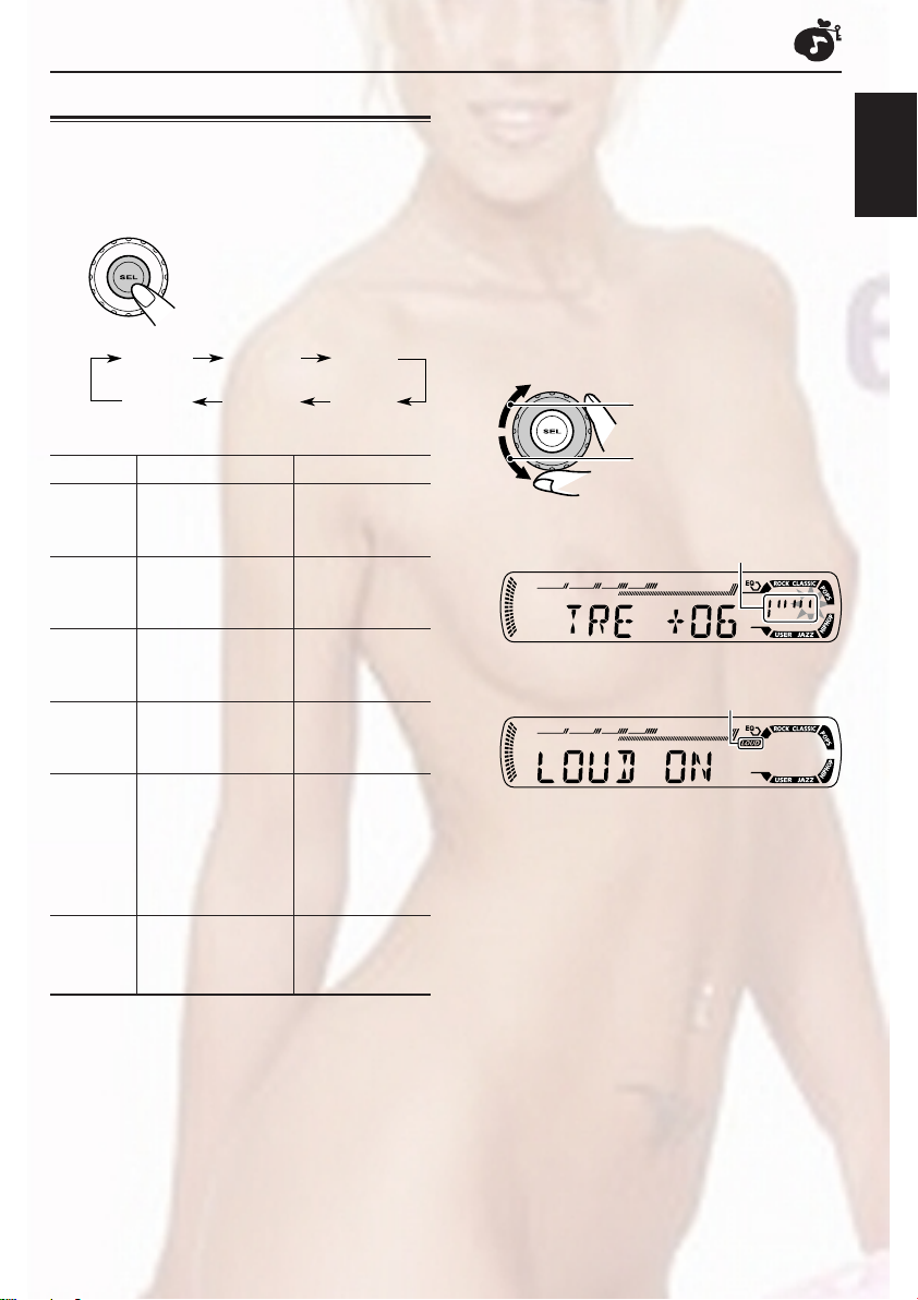
Adjusting the sound
You can adjust the sound characteristics to your
preference.
1
Select the item you want to adjust.
Each time you press the
button, the adjustable items
change as follows:
1
*
When you adjust the bass, treble, or loudness, the
adjustment you have made is stored for the
currently selected sound mode (C-EQ) including
“USER.”
2
*
If you are using a two-speaker system, set the fader
level to “00.”
3
*
Normally the control dial works as the volume
control. So you do not have to select “VOL” to
adjust the volume level.
4
*
Depending on the amplifier gain control setting.
(See page 26 for details.)
ENGLISH
BAS
(bass)
VOL
(volume)
Indication To do: Range
1
BAS*
TRE*
FAD *
BAL Adjust the left L06 (Left only)
LOUD*1Boost low and high
VOL*
Adjust the bass. –06 (min.)
1
Adjust the treble. –06 (min.)
2
Adjust the front R06 (Rear only)
and rear speaker |
balance. F06 (Front only)
and right speaker |
balance. R06 (Right only)
frequencies to
produce a wellbalanced sound
at low volume
level.
3
Adjust the volume. 00 (min.)
TRE
(treble)
LOUD
(loudness)
FAD
(fader)
BAL
(balance)
|
+06 (max.)
|
+06 (max.)
LOUD ON
|
LOUD OFF
|
30 or 50 (max.)*
2
Adjust the setting.
To increase the level or
turn on the loudness
To decrease the level or
turn off the loudness
Indication pattern changes as
you adjust the bass or treble.
Ex. 1: When you adjust “TRE” (treble)
LOUD indicator
Ex. 2: When you turn on the loudness
3
Repeat steps 1 and 2 to adjust the
other items.
To reset each sound mode to the factory
4
settings, repeat the same procedure and
reassign the preset values listed in the table on
page 22.
23
Page 53

OTHER MAIN FUNCTIONS
Changing the general settings
(PSM)
You can change the items listed in the table on
ENGLISH
page 25 by using the PSM (Preferred Setting
Mode) control.
Basic Procedure
1
Press and hold SEL (select) for more
than 2 seconds so that one of the
PSM items appears on the display.
(See page 25.)
2
Select the PSM item you want to
adjust.
3
Adjust the PSM item selected.
4
Repeat steps 2 and 3 to adjust the
other PSM items if necessary.
5
Finish the setting.
24
Ex.: When you select “DIMMER”
Page 54

Preferred Setting Mode (PSM) items
• For detailed operations of each PSM items, refer to the pages listed in the table.
Indications Selectable values/items
DEMO Display demonstration
CLOCK H Hour adjustment
CLOCK M Minute adjustment
DIMMER Dimmer mode
SCROLL Scroll mode
EXT IN* External component
TAG DISP Tag display
AMP GAIN Amplifier gain control
DEMO OFF
ONCE AUTO
CHANGER
TAG OFF TAG ON TAG ON
LOW PWR HIGH PWR HIGH PWR 26
DEMO ON
1 – 12
00 – 59 00 (1:00)
OFF
LINE IN
SIRIUS
Factory-preset See
settings page
DEMO ON
1 (1:00)
OFF 25ONOFF
ONCE
CHANGER
* Only for KD-AR300: Displayed only when one of the following sources is selected—FM, AM, and CD.
To select the dimmer mode—DIMMER
You can dim the display at night (according to
your preference).
When shipped from the factory, dimmer is
deactivated.
• OFF: Cancels the dimmer.
• ON: Activates the dimmer.
To select the scroll mode—SCROLL
You can select the scroll mode for the disc
information (when the entire text cannot be
shown at once).
When shipped from the factory, scroll mode is set
to “ONCE.”
• ONCE: Scrolls only once.
• AUTO: Repeats the scroll (5-second
intervals in between).
• OFF: Cancels scroll mode.
ENGLISH
8
9
25
26
26
Note:
Even if the scroll mode is set to “OFF,” you can scroll
the display by pressing DISP (display) for more than
one second.
CONTINUED ON THE NEXT PAGE
25
Page 55

To select the external component to use
—EXT IN (only for KD-AR300)
You can connect the external component to the
CD changer jack on the rear using an adapter
ENGLISH
specially designed for the external component.
To use the external component as the playback
source through this unit, you need to select
which component—CD changer or external
component—to use.
When shipped from the factory, CD changer is
selected as the external component.
• CHANGER: To use the CD changer.
• LINE IN: To use the external component
• SIRIUS: To use the JVC SIRIUS Radio.
Notes:
• For connecting the Line Input Adapter KS-U57 and
the external component, refer to the Installation/
Connection Manual (separate volume).
• For connecting the JVC SIRIUS Radio, refer to the
SIRIUS Radio Setup Manual (separate volume).
other than CD changer.
To turn the tag display on or off
—TAG DISP
An MP3 file can contain file information called
“ID3 Tag” where its album name, performer, track
title, etc. are recorded.
There are two versions–ID3v1 (ID3 Tag version
1) and ID3v2 (ID3 Tag version 2). If both ID3v1
and ID3v2 are recorded on a disc, ID3v2
information will be shown.
When shipped from the factory, “TAG ON” is
selected.
To select the amplifier gain control
—AMP GAIN
You can change the maximum volume level of
this unit. When the maximum power of the
speakers is less than 50 W, select “LOW PWR”
to prevent them from being damaged.
When shipped from the factory, “HIGH PWR” is
selected.
• LOW PWR: You can adjust the volume level
from “VOL 00” to “VOL 30.”
Note:
If you change the setting from “HIGH
PWR” to “LOW PWR” while
listening at a volume level more than
30, the unit automatically changes the
volume level to “VOL 30.”
• HIGH PWR: You can adjust the volume level
from “VOL 00” to “VOL 50.”
• TAG ON: Turns on the ID3 tag display while
• TAG OFF: Turns off the ID3 tag display while
playing MP3 files.
• If an MP3 file does not have ID3
tags, folder name and file
name appear.
playing MP3 files. (Only the folder
name and file name can be
shown.)
26
Page 56

Detaching the control panel
You can detach the control panel when leaving
the car.
When detaching or attaching the control panel,
be careful not to damage the connectors on the
back of the control panel and on the panel
holder.
Detaching the control panel
Before detaching the control panel, be sure to
turn off the power.
1
Unlock the control panel.
2
Lift and pull the control panel out of
the unit.
Attaching the control panel
1
Insert the left side of the control
panel into the groove on the panel
holder.
2
Press the right side of the control
panel to fix it to the panel holder.
Note on cleaning the connectors:
If you frequently detach the control panel, the
connectors will deteriorate.
To minimize this possibility, periodically wipe the
connectors with a cotton swab or cloth moistened
with alcohol, being careful not to damage the
connectors.
ENGLISH
3
Put the detached control panel into
the provided case.
Connectors
27
Page 57

ENGLISH
CD CHANGER OPERATIONS
This section is only for KD-AR300.
We recommend that you use the JVC MP3compatible CD changer with your unit.
By using this CD changer, you can play back
your original CD-Rs (Recordable) and CD-RWs
(Rewritable) recorded either in audio CD format
or in MP3 format.
• You can also connect other CH-X series CD
changers (except CH-X99 and CH-X100).
However, they are not compatible with MP3
discs, so you cannot play back MP3 discs.
• You cannot use the KD-MK series CD
changers with this unit.
Before operating your CD changer:
• Refer also to the Instructions supplied for
your CD changer.
• If no discs are in the magazine of the CD
changer or the discs are inserted upside
down, “NO DISC” will appear on the display.
If this happens, remove the magazine and
set the discs correctly.
•
If no magazine is loaded in the CD changer, “NO
MAG” appears on the display. If this happens,
insert the magazine in the CD changer.
• If “RESET 1” – “RESET 8” appears on the
display, something is wrong with the
connection between this unit and the CD
changer. If this happens, check the
connection and make sure the cords are
connected firmly. Then, press the reset
button of the CD changer.
Playing discs
Select the CD changer (CD-CH).
CD CD-CH*
* If you have changed “EXT IN” setting to “LINE IN”
or “SIRIUS” (see page 26), you cannot select the
CD changer.
• When the current disc is an MP3 disc:
Playback starts from the first folder of the
current disc once file check is completed.
Selected disc number
MP3 indicator
(folder) indicator Selected folder
number
28
Note:
Folder name appears on the display instead of
“ROOT,” if an MP3 disc contains a folder.
Page 58

• When the current disc is a CD:
Playback starts from the first track of the
current disc.
Selected disc number
Elapsed playing
time
Current track
number
Notes:
• When you press CD CD-CH, the power
automatically comes on. You do not have to press
• If you change the source, CD changer play also
stops. Next time you select the CD changer as the
source, CD changer play starts from where
playback has been stopped previously.
• When you start playing back a CD Text or MP3
disc, disc information will automatically appear on
the display. (See pages 16 and 19.)
to turn on the power.
To go to a particular disc directly
Press the number button corresponding to the
disc number to start its playback (while the CD
changer is playing).
ENGLISH
• To select a disc number from 1 – 6:
Press 1 (7) – 6 (12) briefly.
• To select a disc number from 7 – 12:
Press and hold 1 (7) – 6 (12) for more than
one second.
To fast-forward or reverse the track/file
Press and hold ¢ ,
during play, to fast-forward the
track/file.
Press and hold 4, during play, to reverse
the track/file.
Note:
During this operation, you can only hear intermittent
sounds. (The elapsed playing time also changes
intermittently on the display.)
To skip to the next or previous tracks/files
Press ¢ briefly during
play, to skip ahead to the
beginning of the next track/file.
Each time you press the button
consecutively, the beginning of
the next tracks/files is located
and played back.
Press 4 briefly during play, to skip back to
the beginning of the current track/file.
Each time you press the button consecutively,
the beginning of the previous tracks/files is
located and played back.
29
Page 59

This operation is only possible when
using JVC MP3-compatible CD changer
(CH-X1500).
To go to a track/file quickly (+10 and –10
ENGLISH
buttons)
1 Press MODE to enter the functions mode
while playing a disc.
2 Press +10 or –10.
To skip 10 tracks/files*
forwards to the last track/file
To skip 10 tracks/files*
backwards to the first track/file
* First time you press +10 or –10 button, the
track/file skips to the nearest higher or
lower track/file with a track/file number of
multiple ten (ex. 10th, 20th, 30th).
Then each time you press the button, you can
skip 10 tracks/files (see “How to use the +10
and –10 buttons” below).
• After the last track/file, the first track/file will
be selected, and vice versa.
To skip to the next or previous folder
(only for MP3 discs)
Press 5 (up) while playing an
MP3 disc, to go to the next folder.
Each time you press the button
consecutively, the next folder is
located, and the first file in the
folder starts playback.
Press ∞ (down) while playing an MP3 disc, to go
to the previous folder.
Each time you press the button consecutively,
the previous folder is located, and the first file in
the folder starts playback.
To show the disc information for CD Text
and MP3 discs
This is possible only when connecting a JVC CD
changer equipped with CD Text and/or MP3 disc
information reading capability.
Select text display mode while playing a
CD Text or an MP3 disc.
Note:
If the current playing disc is an MP3 disc, files are
skipped within the same folder.
How to use the +10 and –10 buttons
• Ex. 1: To select track/file number 32 while
playing track/file number 6
(Three times)
Track/file 6 \ 10 \ 20 \ 30 \ 31 \ 32
• Ex. 2: To select track/file number 8 while
playing track/file number 36
(Three times)
Track/file 36 \ 30 \ 20 \ 10 \ 9 \ 8
30
• For details, see page 16 about CD Text disc
information and page 19 about MP3 disc
information.
(Twice)
(Twice)
Page 60

Selecting the playback modes
To play back tracks/files at random
(Folder Random/Disc Random/Magazine
Random Play)
1 Press MODE to enter the
functions mode during play.
2 Press RND (random), while
“MODE” is still flashing on the
display.
Each time you press the button,
the random play mode changes
as follows:
For MP3 discs:
DISC RNDFLDR RND
Canceled
For CDs:
RND indicator
MAG RND
MAG RNDDISC RND
Canceled
To play back tracks/files repeatedly
(Track Repeat/Folder Repeat/Disc Repeat
Play)
1 Press MODE to enter the
functions mode during play.
2 Press RPT (repeat), while
“MODE” is still flashing on the
display.
Each time you press the button,
the repeat play mode changes
as follows:
For MP3 discs:
TRK RPT
Canceled
For CDs:
TRK RPT DISC RPT
(disc) and RPT indicators
Ex.: When you select “DISC RPT”
FLDR RPT
DISC RPT
Canceled
ENGLISH
Ex.: When you select “MAG RND”
Note:
MP3 indicator also lights up if the current playing
disc is an MP3 disc.
Mode
FLDR RND* RND and All files of the
DISC RND RND and All tracks/files of
MAG RND RND indicator All tracks/files of
* “FLDR RND” is only applicable for MP3 discs.
Active
indicator
indicators current folder, then
light up. files of the next
indicators the current (or
light up. specified) disc.
lights up. the inserted discs.
Plays at random
folder and so on.
Note:
MP3 indicator also lights up if the current playing
disc is an MP3 disc.
Mode
TRK RPT RPT indicator The current (or
FLDR RPT* and RPT All files of the
DISC RPT and RPT All tracks/files of
* “FLDR RPT” is only applicable for MP3 discs.
Active
indicator
lights up. specified) track/
indicators current (or
light up. specified) folder
indicators light the current (or
up. specified) disc.
Plays repeatedly
file.
of the current
disc.
31
Page 61

ENGLISH
EXTERNAL COMPONENT OPERATIONS
This section is only for KD-AR300.
Playing an external component
You can connect the external component to the
CD changer jack on the rear using the Line Input
Adapter KS-U57 (not supplied).
Preparations:
• For connecting the Line Input Adapter KS-U57 and
the external component, refer to the Installation/
Connection Manual (separate volume).
• Before operating the external component using the
following procedure, select the external input
correctly. See “To select the external component to
use—EXT IN” on page 26.
1
Select the external component
(LINE IN).
CD LINE IN
• If “LINE IN” does not appear on the display, see
page 26 and select the external input (“LINE IN”).
2
Turn on the connected component
and start playing the source.
3
Adjust the volume.
4
Adjust the sound as you want. (See
pages 22 and 23.)
To use the JVC SIRIUS Radio, refer to the
SIRIUS Radio Setup Manual (separate
volume).
Note on One-Touch Operation:
When you press CD CD-CH, the power automatically
comes on. You do not have to press to turn
on the power.
32
Page 62

TROUBLESHOOTING
What appears to be trouble is not always serious. Check the following points before calling a service
center.
Symptoms
• Sound cannot be heard
from the speakers.
• This unit does not work at
General
all.
• SSM (Strong-station
Sequential Memory)
automatic preset does not
work.
FM/AM
• Static noise while listening
to the radio.
• Disc automatically ejects.
• CD-R/CD-RW cannot be
played back.
• Tracks on the CD-R/CD-RW
cannot be skipped.
• Disc can be neither played
back nor ejected.
Causes
The volume level is set to the
minimum level.
Connections are incorrect.
The built-in microcomputer
may have functioned
incorrectly due to noise, etc.
Signals are too weak.
The antenna is not connected
firmly.
Disc is inserted upside down.
CD-R/CD-RW is not finalized.
Disc is locked.
Remedies
Adjust it to the optimum level.
Check the cords and
connections.
While holding SEL (select),
press (standby/on
attenuator) for more than
2 seconds to reset the unit.
(Your preset adjustments will
also be erased.) (See page 2.)
Store stations manually.
Connect the antenna firmly.
Insert the disc correctly.
• Insert a finalized CD-R/
CD-RW.
• Finalize the CD-R/CD-RW
with the component which
you used for recording.
Unlock the disc.
(See page 16.)
ENGLISH
Disc Playback
• Disc sound is sometimes
interrupted.
•“NO DISC” appears on the
display.
The CD player may have
functioned incorrectly.
You are driving on rough
roads.
Disc is scratched.
Connections are incorrect.
No disc in the loading slot.
Disc is inserted incorrectly.
While holding
(standby/on attenuator), press
0 (eject) for more than
2 seconds. Be careful not to
drop the disc when it is ejected.
Stop playback while driving on
rough roads.
Change the disc.
Check the cords and
connections.
Insert a disc into the loading
slot.
Insert the disc correctly.
33
Page 63

Symptoms
Causes
Remedies
• Disc cannot be played back.
ENGLISH
• Noise is generated.
• A longer readout time is
• Files cannot be played back
MP3 Playback
• Elapsed playing time is not
required (“CHECK” keeps
flashing on the display).
as you have intended them
to play.
correct.
No MP3 files are recorded on
the disc.
MP3 files do not have the
extension code <.mp3> in
their file names.
MP3 files are not recorded in
the format compliant with ISO
9660 Level 1, Level 2, Romeo,
or Joliet.
The file played back is not an
MP3 file (although it has the
extension code <.mp3>).
Readout time varies due to
the complexity of the folder/file
configuration.
Playback order is determined
when the files are recorded.
This sometimes occurs during
play. This is caused by how
the files are recorded on the
disc.
Change the disc.
Add the extension code <.mp3>
to their file names.
Change the disc.
(Record MP3 files using a
compliant application.)
Skip to another file or change
the disc. (Do not add the
extension code <.mp3> to nonMP3 files.)
Do not use too many hierarchies
and folders. Also, do not record
any other types of audio tracks
together with MP3 files.
34
• indicator flashes on the
display.
•“NO FILES” appears on the
display.
• Correct characters are not
displayed (e.g. album
name).
The current folder does not
contain any MP3 file.
The current disc does not
contain any MP3 file.
This unit can only display
alphabets (capital: A–Z),
numbers, and a limited
number of symbols.
Select another folder.
Insert a disc that contains MP3
files.
Page 64

This section is only for KD-AR300.
Symptoms
•“NO DISC” appears on
the display.
•“NO MAG” appears on
the display.
•“RESET 8” appears on
the display.
•“RESET 1” – “RESET 7”
appears on the display.
• The CD changer does not
work at all.
Causes
No disc is in the magazine.
Discs are inserted upside down.
No magazine is loaded in the
CD changer.
This unit is not connected to the
CD changer correctly.
The built-in microcomputer may
function incorrectly due to noise,
etc.
Insert discs into the magazine.
Insert discs correctly.
Insert the magazine.
Connect this unit and the
CD changer correctly and press
the reset button of the CD
changer.
Press the reset button of the
CD changer.
While holding SEL (select),
press (standby/on
attenuator) for more than
2 seconds to reset the unit.
(Your preset adjustments will
also be erased.) (See page 2.)
Remedies
About mistracking:
Mistracking may result from driving on extremely rough roads. This does not damage the unit and the disc,
but will be annoying.
We recommend that you stop disc play while driving on such rough roads.
ENGLISH
CD Changer
35
Page 65

MAINTENANCE
Handling discs
This unit has been designed to reproduce CDs,
CD-Rs (Recordable), CD-RWs (Rewritable), and
CD Texts.
ENGLISH
• This unit is also compatible with MP3 discs.
How to handle discs
When removing a disc
from its case, press down
the center holder of the case
and lift the disc out, holding
it by the edges.
• Always hold the disc by the edges. Do not
touch its recording surface.
When storing a disc into its case, gently insert
the disc around the center holder (with the
printed surface facing up).
• Make sure to store discs into the cases after
use.
To keep discs clean
A dirty disc may not be played
correctly. If a disc does become
dirty, wipe it with a soft cloth in a
straight line from center to edge.
To play new discs
New discs may have some rough
spots around the inner and outer
edges. If such a disc is used, this
unit may reject the disc.
To remove these rough spots, rub
the edges with a pencil or ball-point pen, etc.
Moisture condensation
Moisture may condense on the lens inside the
CD player in the following cases:
• After starting the heater in the car.
• If it becomes very humid inside the car.
Should this occur, the CD player may malfunction.
In this case, eject the disc and leave the unit turned
on for a few hours until the moisture evaporates.
Center holder
When playing a CD-R or CD-RW
Before playing back CD-Rs or CD-RWs, read
their instructions or cautions carefully.
• Use only “finalized” CD-Rs or CD-RWs.
• Some CD-Rs or CD-RWs may not be played
back on this unit because of their disc
characteristics, and for the following reasons:
– Discs are dirty or scratched.
– Moisture condensation on the lens inside the
unit.
– The pickup lens inside the unit is dirty.
• CD-RWs may require a longer readout time
since the reflectance of CD-RWs is lower than
that of regular CDs.
• CD-Rs or CD-RWs are susceptible to high
temperatures or high humidity, so do not leave
them inside your car.
• Do not use following CD-Rs or CD-RWs:
– Discs with stickers, labels, or protective seal
stuck to the surface.
– Discs on which labels can be directly printed
by an ink jet printer.
Using these discs under high temperatures or
high humidity may cause malfunctions or
damage to discs. For example,
– Stickers or labels may shrink and warp a
disc.
– Stickers or labels may be peeled off so discs
cannot be ejected.
– Print on discs may get sticky.
Read instructions or cautions about labels and
printable discs carefully.
CAUTIONS:
• Do not insert 8 cm (3-3/16") discs (single CDs)
into the loading slot. (Such discs cannot be
ejected.)
• Do not insert any disc of unusual shape—like a
heart or flower; otherwise, it will cause a
malfunction.
• Do not expose discs to direct sunlight or any
heat source or place them in a place subject to
high temperature and humidity. Do not leave
them in a car.
• Do not use any solvent (for example,
conventional record cleaner, spray, thinner,
benzine, etc.) to clean discs.
36
Warped
disc
Sticker
Sticker
residue
Disc
Stick-on
label
Page 66

SPECIFICATIONS
AUDIO AMPLIFIER SECTION
Maximum Power Output:
Front: 50 W per channel
Rear: 50 W per channel
Continuous Power Output (RMS):
Front: 19 W per channel into 4 Ω, 40 Hz to
20 000 Hz at no more than 0.8%
total harmonic distortion.
Rear: 19 W per channel into 4 Ω, 40 Hz to
20 000 Hz at no more than 0.8%
total harmonic distortion.
Load Impedance: 4 Ω (4 Ω to 8 Ω allowance)
Tone Control Range
Bass: ±10 dB at 100 Hz
Treble: ±10 dB at 10 kHz
Frequency Response: 40 Hz to 20 000 Hz
Signal-to-Noise Ratio: 70 dB
Line-Out Level/Impedance:
2.5 V/20 kΩ load (full scale)
Output Impedance: 1 kΩ
TUNER SECTION
Frequency Range
FM: 87.5 MHz to 107.9 MHz
AM: 530 kHz to 1 710 kHz
[FM Tuner]
Usable Sensitivity: 11.3 dBf (1.0 µV/75 Ω)
50 dB Quieting Sensitivity:
16.3 dBf (1.8 µV/75 Ω)
Alternate Channel Selectivity (400 kHz):
65 dB
Frequency Response: 40 Hz to 15 000 Hz
Stereo Separation: 35 dB
Capture Ratio: 1.5 dB
CD PLAYER SECTION
Type: Compact disc player
Signal Detection System: Non-contact optical
pickup (semiconductor laser)
Number of channels: 2 channels (stereo)
Frequency Response: 5 Hz to 20 000 Hz
Dynamic Range: 96 dB
Signal-to-Noise Ratio: 98 dB
Wow and Flutter: Less than measurable limit
MP3 decoding format:
MPEG1/2 Audio Layer 3
Max. Bit Rate: 320 Kbps
GENERAL
Power Requirement:
Operating Voltage:
DC 14.4 V (11 V to 16 V allowance)
Grounding System: Negative ground
Allowable Operating Temperature:
0°C to +40°C (32°F to 104°F)
Dimensions (W × H × D):
Installation Size (approx.):
182 mm × 52 mm × 150 mm
(7-3/16" × 2-1/16" × 5-15/16")
Panel Size (approx.):
188 mm × 58 mm × 11 mm
(7-7/16" × 2-5/16" × 7/16")
Mass (approx.):
1.4 kg (3.1 lbs) (excluding accessories)
Design and specifications are subject to change
without notice.
ENGLISH
[AM Tuner]
Sensitivity: 20 µV
Selectivity: 35 dB
If a kit is necessary for your car, consult your
telephone directory for the nearest car audio
speciality shop.
37
Page 67

http://www.jvcmobile.c
Visit us on-line for
Technical Support & Customer Satisfaction Survey.
US RESIDENTS ONLY
om
Having TROUBLE with operation?
Please reset your unit
Refer to page of How to Reset
Still having trouble??
USA ONLY
Call 1-800-252-5722
http://www.jvc.com
We can help you!
EN, SP, FR 1203KKSMDTJEIN
© 2003 VICTOR COMPANY OF JAPAN, LIMITED
Page 68

31 2
4
Ÿ
~
⁄
@
¤
!
3
2
1
53 mm
(2-1/8")
184 mm
(7-1/4")
GET0211-002A
[J]
KD-AR300/KD-G300
Installation/Connection Manual
Manual de instalación/conexión
Manuel d’installation/raccordement
1203KKSMDTJEIN
EN, SP, FR
ENGLISH
This unit is designed to operate on 12 V DC, NEGATIVE ground
electrical systems. If your vehicle does not have this system, a
voltage inverter is required, which can be purchased at JVC car
audio dealers.
Parts list for installation and connection
The following parts are provided with this unit.
After checking them, please set them correctly.
A / B
Hard case/Control panel
Estuche duro/Panel de
control
Etui de transport/Panneau
de commande
G
Washer (ø5)
Arandela (ø5)
Rondelle (ø5)
H
Lock nut (M5)
Tuerca de seguridad (M5)
Ecrou d’arrêt (M5)
C
Sleeve
Cubierta
Manchon
I
Mounting bolt—M5 x 20 mm (M5 x 13/16")
Perno de montaje—M5 x 20 mm
(M5 x 13/16 pulgada)
Boulon de montage—M5 x 20 mm
(M5 x 13/16 pouces)
ESPAÑOL
Esta unidad está diseñada para funcionar con 12 V de CC, con
sistemas eléctricos de masa NEGATIVA. Si su vehículo no
posee este sistema, será necesario un inversor de tensión, que
puede ser adquirido en los concesionarios de JVC de equipos
de audio para automóviles.
Lista de piezas para instalación y conexión
Con esta unidad se suministran las siguientes piezas.
Después de inspeccionarlas, colóquelas correctamente.
D
Trim plate
Placa de guarnición
Plaque d’assemblage
J
Rubber cushion
Cojín de goma
Amortisseur en caoutchouc
E
Power cord
Cordón de alimentación
Cordon d’alimentation
FRANÇAIS
Cet appareil est conçu pour fonctionner sur des sources de
courant continu de
n’offre pas ce type d’alimentation, il vous faut un convertisseur de
tension, que vous pouvez acheter chez un revendeur
d’autoradios JVC.
12 V à masse NEGATIVE
Liste des pièces pour l’installation et
raccordement
Les pièces suivantes sont fournies avec cet appareil.
Après vérification, veuillez les placer correctement.
F
Remote controller
Control remoto
Télécommade
K
Handles
Manijas
Poignées
. Si votre véhicule
L
Battery
Pila
Pile
CR2025
INSTALLATION
(IN-DASH MOUNTING)
The following illustration shows a typical installation. If you have
any questions or require information regarding installation kits,
consult your JVC car audio dealer or a company supplying kits.
• If you are not sure how to install this unit correctly, have it
installed by a qualified technician.
B
D
INSTALACION (MONTAJE EN EL
TABLERO DE INSTRUMENTOS)
La siguiente ilustración muestra una instalación típica. Si tiene
alguna pregunta o necesita información acerca de las
herramientas para instalación, consulte con su concesionario de
JVC de equipos de audio para automóviles o a una compañía
que suministra tales herramientas.
• Si usted no está seguro de cómo instalar correctamente la
unidad, hágala instalar por un técnico cualificado.
Do the required electrical connections.
Realice las conexiones eléctricas
requeridas.
Réalisez les connexions électriques.
INSTALLATION (MONTAGE DANS LE
TABLEAU DE BORD)
L’illustration suivante est un exemple d’installation typique. Si
vous avez des questions ou avez besoin d’information sur des
kits d’installation, consulter votre revendeur d’autoradios JVC ou
une compagnie d’approvisionnement.
•
Si l’on n’est pas sûr de pouvoir installer correctement cet
appareil, le faire installer par un technicien qualifié.
J
C
K
*1
C
Removing the unit
Before removing the unit, release the rear section.
B
I
1
When you stand the unit, be
*
careful not to damage the fuse on
the rear.
1
Al poner la unidad vertical, tenga
*
cuidado de no dañar el fusible
provisto en la parte posterior.
1
Lorsque vous mettez l’appareil à
*
la verticale, faire attention de ne
pas endommager le fusible situé
sur l’arrière.
Extracción de la unidad
Antes de extraer la unidad, libere la sección trasera.
D
B
Retrait de l’appareil
Avant de retirer l’appareil, libérer la section arrière.
Bend the appropriate tabs to hold the
sleeve firmly in place.
Doble las lengüetas apropiadas para
retener firmemente la manga en su
lugar.
Tordez les languettes appropriées
pour maintenir le manchon en place.
D
Insert the two handles, then pull them as illustrated so that the
unit can be removed.
Inserte las dos manijas y, a continuación, extráigalas de la
manera indicada en la ilustración para poder desmontar la
unidad.
Insérez les deux poignées, puis tirez de la façon illustrée de
façon à retirer l’appareil.
K
1
Page 69

When using the optional stay / Cuando emplea un soporte
L
R
+
-
+
-
+
-
+
-
L
R
+
-
+
-
+
-
+
-
L
R
+
-
+
-
+
-
+
-
opcional / Lors de l’utilisation du hauban en option
Fire wall
Dashboard
Tablero de instrumentos
Tableau de bord
Tabique a prueba
de incendios
Cloison
G
I
C
Install the unit at an angle of less than 30˚.
Instale la unidad a un ángulo de menos
de 30˚.
Installez l’appareil avec un angle de moins
de 30˚.
Stay (option)
Soporte (opción)
Hauban (en option)
H
Screw (option)
Tornillo (opción)
Vis (en option)
When installing the unit without using the sleeve / Instalación de la unidad sin utilizar
la cubierta / Lors de l’installation de l’appareil scans utiliser de manchon
In a Toyota for example, first remove the car radio and install the unit in its place.
En un Toyota por ejemplo, primero retire la radio del automóvil y luego instale la unidad en su lugar.
Par exemple dans une Toyota, retirer d’abord l’autoradio et installer l’appareil à la place.
Flat type screws—M5 x 8 mm (M5 x 3/8")*
Tornillos tipo plano—M5 x 8 mm (M5 x 3/8 pulgada)*
Vis à tête plate—M5 x 8 mm (M5 x 3/8 pouces)
Bracket*
Ménsula*
Support
Pocket
Compartimiento
Poche
*
*
Bracket*
Ménsula*
Support
*
Note : When installing the unit on the mounting bracket, make sure to use the 8 mm (3/8") -long screws. If
longer screws are used, they could damage the unit.
Nota : Cuando instala la unidad en la ménsula de montaje, asegúrese de utilizar los tornillos de 8 mm
(3/8 pulgada) de longitud. Si se utilizan tornillos más largos, éstos pueden dañar la unidad.
Remarque :
Lors de l’installation de l’appareil sur le support de montage, s’assurer d’utiliser des vis d’une
longueur de 8 mm (3/8 pouces). Si des vis plus longues sont utilisées, elles peuvent endommager
l’appareil.
* Not included with this unit.
* No suministrado con esta unidad.
*
Non fourni avec cet appareil.
Flat type screws—M5 x 8 mm
(M5 x 3/8")*
Tornillos tipo plano—M5 x 8 mm
(M5 x 3/8 pulgada)*
Vis à tête plate—M5 x 8 mm
(M5 x 3/8 pouces)*
ELECTRICAL CONNECTIONS
To prevent short circuits, we recommend that you disconnect the
battery’s negative terminal and make all electrical connections
before installing the unit.
• Be sure to ground this unit to the car’s chassis again after
installation.
Notes:
• Replace the fuse with one of the specified rating. If the fuse
blows frequently, consult your JVC car audio dealer.
• It is recommended to connect to the speakers with maximum
power of more than 50 W (both at the rear and at the front, with
an impedance of 4 Ω to 8 Ω). If the maximum power is less
than 50 W, change “AMP GAIN” setting to prevent the speakers
from being damaged (see page 26 of the INSTRUCTIONS).
• To prevent short-circuit, cover the terminals of the UNUSED
leads with insulating tape.
• The heat sink becomes very hot after use. Be careful not to
touch it when removing this unit.
Heat sink
Sumidero térmico
Dissipateur de chaleur
CONEXIONES ELECTRICAS
Para evitar cortocircuitos, recomendamos que desconecte el
terminal negativo de la batería y que efectúe todas las
conexiones eléctricas antes de instalar la unidad.
• Asegúrese de volver a conectar a masa esta unidad al
chasis del automóvil después de la instalación.
Notas:
• Reemplace el fusible por uno con la corriente especificada. Si
el fusible se quemase frecuentemente consulte con su
concesionario de JVC de equipos de audio para automóviles.
• Se recomienda conectar los altavoces con una potencia
máxima de más de 50 W (tanto atrás como adelante, con una
impedancia de 4 Ω a 8 Ω). Si la potencia máxima es de menos
de 50 W, cambie “AMP GAIN” para evitar daños en los
altavoces (consulte la página 26 del MANUAL DE
INSTRUCCIONES).
• Para evitar cortocircuitos, cubra los cables NO UTILIZADOS
con cinta aislante.
• El sumidero térmico estará muy caliente después del uso.
Asegúrese de no tocarlo al desmontar esta unidad.
RACCORDEMENTS ELECTRIQUES
Pour éviter tout court-circuit, nous vous recommandons de
débrancher la borne négative de la batterie et d’effectuer tous les
raccordements électriques avant d’installer l’appareil.
• Assurez-vous de raccorder de nouveau la mise à la masse
de cet appareil au châssis de la voiture après l’installation.
Remarques:
Remplacer le fusible par un de la valeur précisée. Si le fusible
•
saute souvent, consulter votre revendeur d’autoradios JVC.
•
Il est recommandé de connecter des enceintes avec une
puissance de plus de 50 W (les enceintes arrière et les
enceintes avant, avec une impédance comprise entre
4 Ω et 8 Ω
changez “AMP GAIN” pour éviter d’endommager vos enceintes
(voir page 26 du MANUEL D’INSTRUCTIONS).
•
Pour éviter les court-circuits, couvrir les bornes des fils qui ne
sont PAS UTILISÉS avec de la bande isolante.
•
Le dissipateur de chaleur devient très chaud après usage. Faire
attention de ne pas le toucher en retirant cet appareil.
). Si la puissance maximum est inférieure à 50 W,
PRECAUTIONS on power supply and speaker
connections:
• DO NOT connect the speaker leads of the power cord to
the car battery; otherwise, the unit will be seriously
damaged.
• BEFORE connecting the speaker leads of the power cord to
the speakers, check the speaker wiring in your car.
TROUBLESHOOTING
• The fuse blows.
* Are the red and black leads connected correctly?
• Power cannot be turned on.
* Is the yellow lead connected?
• No sound from the speakers.
* Is the speaker output lead short-circuited?
• Sound is distorted.
* Is the speaker output lead grounded?
* Are the “–” terminals of L and R speakers grounded in
common?
• Noise interfere with sounds.
* Is the rear ground terminal connected to the car’s chassis using
shorter and thicker cords?
• Unit becomes hot.
* Is the speaker output lead grounded?
* Are the “–” terminals of L and R speakers grounded in
common?
PRECAUCIONES sobre las conexiones de la fuente
de alimentación y de los altavoces:
• NO conecte los conductores de altavoz del cable de
alimentación a la batería de automóvil, pues podrían
producirse graves daños en la unidad.
• ANTES de conectar a los altavoces los conductores de altavoz
del cable de alimentación, verifique el conexionado de altavoz
de su automóvil.
LOCALIZACION DE AVERIAS
• El fusible se quema.
* ¿Están los conductores rojo y negro correctamente
conectados?
• No es posible conectar la alimentación.
* ¿Está el cable amarillo conectado?
• No sale sonido de los altavoces.
* ¿Está el cable de salida del altavoz cortocircuitado?
• El sonido presenta distorsión.
* ¿Está el cable de salida del altavoz conectado a masa?
* ¿Están los terminales “–” de los altavoces L y R conectados a
una masa común?
• Perturbación de ruido.
* ¿El terminal de tierra trasero está conectado al chasis del
automóvil utilizando los cordones más corto y más grueso?
• La unidad se calienta.
* ¿Está el cable de salida del altavoz conectado a masa?
* ¿Están los terminales “–” de los altavoces L y R conectados a
una masa común?
2
PRECAUTIONS sur l’alimentation et la connexion
des enceintes:
• NE CONNECTEZ PAS les fils d’enceintes du cordon
d’alimentation à la batterie; sinon, l’appareil serait
sérieusement endommagé.
AVANT de connecter les fils d’enceintes du cordon
•
d’alimentation aux enceintes, vérifiez le câblage des enceintes
de votre voiture.
EN CAS DE DIFFICULTES
• Le fusible saute.
*
Les fils rouge et noir sont-ils racordés correctement?
• L’appareil ne peut pas être mise sous tension.
Le fil jaune est-elle raccordée?
*
• Pas de son des enceintes.
Le fil de sortie d’enceinte est-il court-circuité?
*
• Le son est déformé.
*
Le fil de sortie d’enceinte est-il à la masse?
*
Les bornes “–” des enceintes gauche et droit sont-elles mises
ensemble à la masse?
• Interférence avec les sons.
La prise arrière de mise à la terre est-elle connectée au châssis
*
de la voiture avec un cordon court et épais?
• L’appareil devient chaud.
*
Le fil de sortie d’enceinte est-il à la masse?
*
Les bornes “–” des enceintes gauche et droit sont-elles mises
ensemble à la masse?
Page 70

1
*
1
*
1
1
2
3
4
5
15
2
3
ENGLISH ESPAÑOL FRANÇAIS
Typical Connections / Conexiones tipicas / Raccordements typiques
A
Before connecting: Check the wiring in the vehicle carefully.
Incorrect connection may cause serious damage to this unit.
The leads of the power cord and those of the connector from the
car body may be different in color.
1
Connect the colored leads of the power cord in the order
specified in the illustration below.
2
Connect the antenna cord.
3
Finally connect the wiring harness to the unit.
To CD changer or another external component (see diagram )
(Only for KD-AR300)
Al cambiador de CD u otro componente externo (véase diagrama )
(Sólo para KD-AR300)
Au changeur de CD ou à un autre appareil extérieur (voir le
diagramme ) (Seulement pour le KD-AR300)
Rear ground terminal
Terminal de tierra
posterior
Borne arrière de masse
Antes de la conexión: Verifique atentamente el conexionado
del vehículo. Una conexión incorrecta podría producir daños
graves en la unidad.
Los cordones del cable de alimentación y los del conector
procedentes de la carrocería del automóvil podrían ser de
diferentes en color.
1
Conecte los conductores de color del cable de alimentación
en el orden especificado en la ilustración de abajo.
2
Conecte el cable de antena.
3
Por último, conecte el cable de alimentación a la unidad.
15 A fuse
Fusible de 15 A
Fusible 15 A
Avant de commencer la connexion:
Vérifiez attentivement le
câblage du véhicule. Une connexion incorrecte peut
endommager sérieusement l’appareil.
Le fil du cordon d’alimentation et ceux des connecteurs du
châssis de la voiture peuvent être différents en couleur.
1
Connectez les fils colorés du cordon d’alimentation dans
l’ordre spécifié sur l’illustration ci-dessous.
2
Connectez le cordon d’antenne.
3
Finalement, connectez le faisceau de fils à l’appareil.
Antenna terminal
Terminal de la antena
Borne de l’antenne
Line out (see diagram )
Salida de línea
(véase diagrama )
Sortie de ligne
(voir le diagramme )
1
*
Not included with this unit
1
*
No suministrado con esta unidad
1
*
Non fourni avec cet appareil
Ignition switch
Interruptor de encendido
Interrupteur d’allumage
Black
Negro
Noir
To metallic body or chassis of the car
A un cuerpo metálico o chasis del automóvil
Vers corps métallique ou châssis de la voiture
2
Yellow*
Amarillo*
Jaune
*
2
2
To a live terminal in the fuse block connecting to the car battery
(bypassing the ignition switch) (constant 12 V)
A un terminal activo del bloque de fusibles conectado a la batería del
automóvil (desviando el interruptor de encendido) (12 V constantes)
A une borne sous tension du porte-fusible connectée à la batterie de
la voiture (en dérivant l’interrupteur d’allumage) (12 V constant)
Fuse block
Bloque de fusibles
Porte-fusible
2
*
Before checking the operation of this unit prior to
installation, this lead must be connected, otherwise
power cannot be turned on.
2
*
Antes de comprobar el funcionamiento de esta
unidad previa a de la instalación, es necesario
conectar este cable, de lo contrario no se podrá
conectar la alimentación.
2
*
Pour vérifier le fonctionnement de cet appareil avant
installation, ce fil doit être raccordé, sinon l’appareil ne
peut pas être mis sous tension.
White with black stripe
Blanco con rayas
negras
Blanc avec bande noire
White
Blanco
Blanc
Gray with black stripe
Gris con rayas negras
Gris avec bande noire
Red
Rojo
Rouge
Blue with white stripe
Azul con rayas blancas
Bleu avec bande blanche
Gray
Gris
Gris
Green with black stripe
Verde con rayas negras
Vert avec bande noire
To an accessory terminal in the fuse block
A un terminal accesorio del bloque de fusibles
Vers borne accessoire du porte-fusible
To the remote lead of other equipment or automatic antenna if any (200 mA max.)
Al conductor remoto de otro equipo o de la antena automática, si hubiere
(máx. 200 mA)
Au fil de télécommande de l’autre appareil ou à l’antenne automatique s’il y en a une
(200 mA max.)
Green
Verde
Ver t
Purple with black stripe
Púrpura con rayas negras
Violet avec bande noire
Purple
Púrpura
Violet
Left speaker (front)
Altavoz izquierdo (frontal)
Enceinte gauche (avant)
Right speaker (front)
Altavoz derecho (frontal)
Enceinte droit (avant)
Left speaker (rear)
Altavoz izquierdo (trasero)
Enceinte gauche (arrière)
3
Right speaker (rear)
Altavoz derecho (trasero)
Enceinte droit (arrière)
Page 71
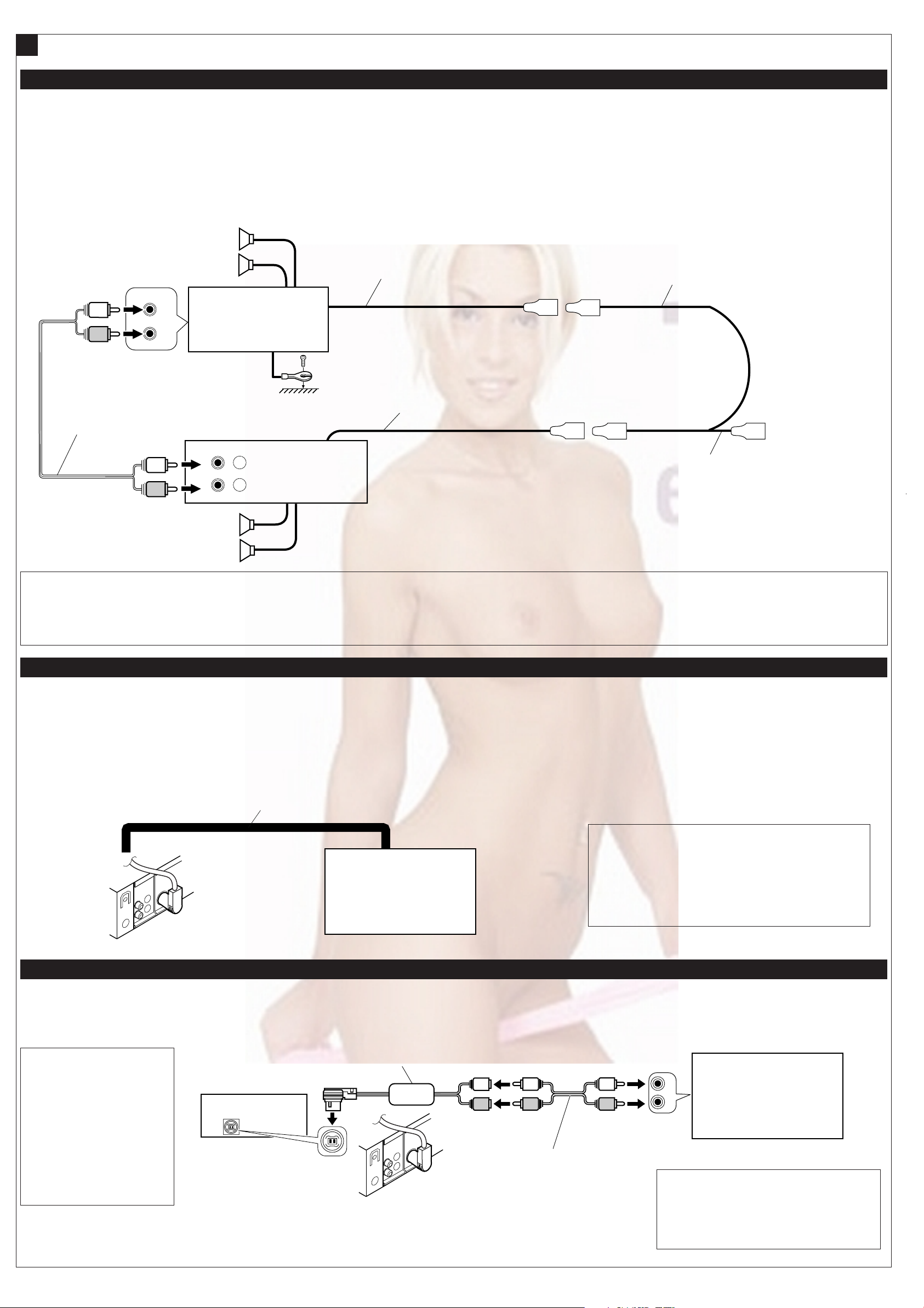
L L
R
L
L
R
RR
L
LRL
R
INPUT
R
L
R
R
LINE
REAR
FRONT
OUT
L
*
3
Connections Adding Other Equipment / Conexiones para añadir otros equipos / Raccordement pour ajouter d’autres appareils
B
Amplifier / Amplificador / Amplificateur
You can connect an amplifier and other equipment to upgrade
your car stereo system.
• Connect the remote lead (blue with white stripe) to the remote
lead of the other equipment so that it can be controlled
through this unit.
• For amplifier only:
Disconnect the speakers from this unit, connect them to
the amplifier. Leave the speaker leads of this unit unused.
Rear speakers
Altavoces posteriores
Enceintes arrière
JVC Amplifier
Amplificador de JVC
JVC Amplificateur
Signal cord (not supplied with this unit)
Cable de señal (no suministrado con esta unidad)
Cordon de signal (non fourni avec cet appareil)
Usted podrá conectar un amplificador y otros equipos para
mejorar el sistema estéreo de su automóvil.
• Conecte el conductor remoto (azul con rayas blancas) al
conductor remoto del otro equipo para poderlo controlar a
través de esta unidad.
• Sólo para el amplificador:
Desconecte los altavoces de esta unidad y conéctelos al
amplificador. Los cables de los altavoces de esta unidad
quedan sin usar.
Remote lead
Cable remoto
Fil d’alimentation à distance
Remote lead (Blue with white stripe)
Cable remoto (Azul con rayas blancas)
Fil d’alimentation à distance (Bleu avec bande blanche)
Vous pouvez connecter un amplificateur ou autre appareil pour
améliorer votre système autoradio.
•
Connectez le fil de commande à distance (bleu avec bande
blanche) au fil de commande à distance de l’autre appareil de
façon qu’il puisse être commandé via cet appareil.
Pour l’amplificateur seulement:
•
Déconnectez les enceintes de cet appareil et connectezles à l’amplificateur. Laissez les fils d’enceintes de cet
appareil inutilisés.
Y-connector (not supplied with this unit)
Conector en Y (no suministrado con esta unidad)
Connecteur Y (non fourni avec cet appareil)
KD-AR300/
Front speakers
Altavoces delanteros
Enceintes avant
*3Firmly attach the ground wire to the metallic body or to the
chassis of the car—to the place not coated with paint (if
coated with paint, remove the paint before attaching the
wire). Failure to do so may cause damage to the unit.
CD Changer / Cambiador de CD / Changeur CD
Only for KD-AR300
Sólo para KD-AR300
Seulement pour le KD-AR300
Refer also to page 28 of the INSTRUCTIONS.
Consulte también la página 28 de las MANUAL DE INSTRUCCIONES.
Référez-vous aussi à la page 28 du MANUEL D’INSTRUCTIONS.
To the remote lead of other equipment or automatic antenna if any
KD-G300
Al conductor remoto de otro equipo o de la antena automática, si hubiere
Au fil de télécommande de l’autre appareil ou à l’antenne automatique s’il y en a une
*3Fije firmemente el cable de tierra a la carrocería metálica o al
chasis—a un lugar no cubierto con pintura (si está cubierto
con pintura, quítela antes de fijar el cable). De lo contrario, se
podrían producir daños en la unidad.
3
*
Attachez solidement le fil de mise à la masse au châssis
métallique de la voiture—à un endroit qui n’est pas
recouvert de peinture (s’il est recouvert de peinture, enlevez
d’abord la peinture avant d’attacher le fil). L’appareil peut
être endommagé si cela n’est pas fait correctement.
Connecting cord supplied for your CD changer
Cable de conexión suministrado con su cambiador de CD
Cordon de connexion fourni avec votre changeur CD
Cambiador de CD de JVC
Changeur CD JVC
KD-AR300
External Component / Componente exterior / Appareil extérieur
Only for KD-AR300
Sólo para KD-AR300
Seulement pour le KD-AR300
For connecting the JVC SIRIUS
Radio, refer to the SIRIUS
Radio Setup Manual (separate
volume).
Para la conexión de la radio
JVC SIRIUS, consulte el Manual
de configuración de la radio
SIRIUS (volumen separado).
Pour brancher la radio JVC
SIRIUS, référez-vous au Manuel
d’installation de la radio SIRIUS
(volume séparé).
KD-AR300
CD changer jack
Jack para el cambiador de CD
Prise du changeur CD
JVC CD changer
KS-U57 *
4
CAUTION / PRECAUCION / PRECAUTION:
• Before connecting the CD changer, make sure that the unit
is turned off.
• Antes de conectar el cambiador de CD, asegúrese de que
la unidad esté apagada.
Avant de connecter le changeur CD, s’assurer que l’unité
•
est éteinte.
Signal cord (not supplied with this unit)
Cable de señal (no suministrado con esta unidad)
Cordon de signal (non fourni avec cet appareil)
External component
Componente exterior
Appareil extérieur
4
*
Line Input Adapter KS-U57 (not supplied with this
unit)
4
*
Adaptador de entrada de línea KS-U57 (no
suministrado con esta unidad)
4
*
Adaptateur d’entrée de ligne KS-U57 (non fourni
avec cet appareil)
4
Page 72

SCHEMATIC DIAGRAMS
CD RECEIVER
KD-AR300,KD-G300
CD-ROM No.SML200401
Area suffix
J -------------- Northern America
KD-AR
300
S
Contents
Block diagram
Standard schematic diagrams
Printed circuit boards
KD-G300
S
ARSENAL rogo
CD CHANGER CONTROL
KD-AR300J
KD-G300J
2-1
2-2
2-5 to 7
COPYRIGHT 2004 VICTOR COMPANY OF JAPAN, LTD.
No.MA036SCH
2004/1
Page 73

Safety precaution
!
!
Burrs formed during molding may be left over on some parts of the chassis. Therefore,
pay attention to such burrs in the case of preforming repair of this system.
Please use enough caution not to see the beam directly or touch it in case of an
adjustment or operation check.
Page 74

Block diagram
POSITION SET
SWITCH
LOAD&FEED
MOTOR
SPINDLE
MOTOR
SW1, SW2
PICK UP
IC681
REMOCON
LCD1
PSW
FEED+
FEED-
SPINDLE+
SPINDLE-
SW1, SW2
VF1,VF2
VT1,VT2
LD,MD
TRACKING+
TRACKINGFOCUS+
FOCUS-
REMOCON
CN501
S601 to S618
KEY MATRIX
KEY0
KEY1
KEY2
SW1,SW2,PSW
SPINDLE+
SPINDLEFEED+
FEEDTRACKING+
TRACKINGFOCUS+
FOCUS-
VF1,VF2,
VT1,VT2,
MD,LD
ENC1
ENC2
CJ601
LM0
LM1
IC501
CD
DRIVER
KEY0
KEY1
KEY2
LCDCL
LCDDA
LCDCE
REMOCON
CN701
ENC1
ENC2
DMO,FMO
TRO,FOO
RFGC,RF
RFRP,RFDC
TEB,SEL
TE,FE
IC521
RF AMP
IC541
DSP
BUCK
LRCK
AOUT
BUCK
AOUT
BUCK
LRCK
AOUT
BUS0 to BUS3
BUCK,CCE
RST
CDRW
DAC-CDTI
DAC-CCLK
DAC-CSN
DAC-PDN
IC481
DAC
IC401
MP3/WMA LSI
& INT.SRAM
J1
ANT
IC31
PLL
PLLCE
PLLDA
PLLCL
PLLDI
MP3STBY
MP3CLK
MP3DOUT
MP3RESET
MP3REQ
MP3DIN
FM/AM OSC
FM VT
AM VT
IC701
CPU
TU1
FM/AM
TUNER
SD/ST
MONO
SM,IFC-CONT
FM/AM
SEEK/STOP
AOUTLAOUTL+
AOUTRAOUTR+
SI,SO,I/O
INT,SCK
SI
L-CH
R-CH
VOLDA
VOLCL
IC581
CD L.P.F.
IC801
JVC BUS
IC161
E.VOLUME
CD.L
CD.R
CH.SCK
OUTLF
OUTLR
OUTRF
OUTRR
IC901
REGULATOR
EACH BLOCK
CH.L
CH.R
REAR L
REAR R
J801
CD CHANGER
J321
LINE OUT
IC301
POWER
AMP.
FRONT LEFT (+)
FRONT LEFT (-)
FRONT RIGHT (+)
FRONT RIGHT (-)
REAR LEFT (+)
REAR LEFT (-)
REAR RIGHT (+)
REAR RIGHT (-)
CN901
SPK
BATTERY
CONTROL
COM1
COM2
COM3
S1 to S52
IC601
LCD
DRIVER
LCDCL
LCDDA
LCDCE
JS686
ENCODER
ONLY USED FOR
KD-AR300J
2-1
Page 75

Standard schematic diagrams
Main amplifier section
J1
QNB0100-002
C8
C36
7p
X31
QAX0616-001Z
IC31
TB2118F-X
C35
10p
R37
2.2k
PLLCE
R36
2.2k
PLLDA
R35
2.2k
PLLCL
R34
2.2k
PLLDI
R33
10k
R32
6.2k
C34
0.047
9V
CD.R
CD.L
PSW
SW1
SW2
LM0
LM1
BUS0
BUS1
BUS2
BUS3
(SHEET 2)
To CJ601
(SHEET 3)
BUCK
CCE
RST
CD8V
MP3REQ
MP3RESET
MP3STBY
MP3DIN
MP3DOUT
MP3CLK
DAC-CDTI
DAC-CCLK
DAC-CSN
DAC-PDN
CDRW
SW5V
CDON
DETACH
10V
ACC5V
REMOCON
ENC1
ENC2
LCDCL
LCDDA
LCDCE
KEY0
KEY1
KEY2
CN701
VMC0334-001
J801
QNZ0095-001
D701
0.047
C357
D702
D703
D704
CH.R
A-GND
CH.L
D705
47/6.3
D706
C802
0.01
C33
D707
QAU0312-001
C37
10p
C48
0.047
UN2211-X
D709
D708
47K
R802
L1
4.7u
100k
R804
TU1
1SS355-X
D1
C38
0.001
C40
10/16
0.047
C41
C46
C47
R43
470
C32
47p
Q31
D712
C718
R805
R803
100
D2
R38
0.01
C42
0.01
0.01
10
0.1
1SS355-X
100
0.047
C43
R44
220
C50
100p
C716
0.01
C6
0
R39
39k
10k
0.0027
R40
R41
C44
0.01
C49
R42
0.001
100/10
C31
R911
1K
UN2211-X
0.1
0.1
C717
R806
IC801
HD74HC126FP-X
C45
C39
1000P
Q902
22/16
C1
FM/AM
R910
C2
4.7k
SD/ST
R31
UN2111-X
10k
0.047
R7
10
10k
Q901
D713
220/10
C4
2SB624/4/-X
Q6
Q7
UN2211-X
Q10
IFC-CONT
R904
0.01
C801
0.047
C3
5.6K
R810
100
D243
R248
RB160M-30-X
220
D244
R161
220k
C81
1/50
1/50
C91
47
22/16
R9
C7
R5
47k
Q5
2SB709A/R/-X
D5
D4
1SS355-X
1SS355-X
R6
47k
R4
3.3k
R10
R808
SI
330
UN2211-X
R809
22k
R801
47k
10k
SO
R807
100K
SCK
SI
SO
I/O
INT
SCK
D51
SEEK/STOP
R811
R51
R52
R2
47k
27K
SM
CDON
VOLDA
VOLCL
BUCK
CCE
RST
BUS0
BUS1
BUS2
BUS3
CDRW
330P
C51
C772
C706
R777
R778
R1
0.1/50
C5
Q1
2SD601A/QR/-X
12
MONO
IC701
UPD784217AGC238
R720
R719
R709
0.1
0.047
VDD
R776
R775
R774
R773
R760
R759
R716
R715
R717
R714
R713
R712
R711
R710
3.3k
R708
R707
R706
R704
R705
C84
C83
C93
C94
10k
R763
1.2k
0
47k
470
470
470
10K
470
470
470
470
VPP
47k
47k
47k
47k
C770
0.047
R758
R81
R91
R92
C92
47k
DIMIN
PLLDI
PLLCL
PLLDA
TELMUTE
1k
10k
VSS
R721
R722
SW2
R703
R702
R755
0
0
10M
PSW
LM0
LM1
X1
C705
C704
4.7u
0.047
QAX0617-001Z QAX0401-001
R754
X701
R82
PLLCE
8P
FM/AM
820
C703
C82
SEEK/STOP
IFC-CONT
10k
R723
X702
27p
C702
R701
27p
47k
C701
TU.L
CH.L
CD.L
CD.R
TU.R
CH.R
10k
R725
MP3REQ
MP3RESET
SW1
INT
22p
MP3STBY
MP3DOUT
47k
R753
C173
C172
C171
C161
C162
C163
MP3DIN
MONO
10k
R726
47k
R752
1/50
1/50
1/50
1/50
1/50
1/50
MP3CLK
R751
REMOCON
C708
0.047
SD/ST
10k
R728
10k
DAC-PDN
DAC-CDTI
R750
ENC1
RESET
R172
22k
C174
0.0082
C164
0.0082
C192C191
R162
100/1047/16
22k
DAC-CSN
DAC-CCLK
R729
47k
R771
47k
R734
2.2k
R735
R736
4.7k
4.7k
4.7k
TD
R741
R772
R743
R744
R745
R746
10k
1SS355-X
R756
47k
C709
D710
LCDCE
2.2k
LCDCL
2.2k
LCDDA
R737
0
I/O
R738
SCK
R739
SO
R740
SI
RD
10k
10k
10k
KEY2
10k
KEY1
10k
KEY0
ENC2
10k
4.7k
R747
R748
4.7k
R749
4.7k
0
R765
47k
R767
47k
R766
IC702
IC-PST3433U-X
C710
0.1
47/6.3
C175
0.22
C166
0.22
C165
0.22
0.1
LEVEL
C707
SM
2.2k
R173
C176
R163
2.2k
220k
R171
C177
0.033
0.22
C167
0.033
DIMIN
TELMUTE
R757
2.2k
UDZS5.1B-X
1SS355-X
L701
4.7u
C711
220/6.3
C713
0.1
C771
0.047
C712
0.01
C244
0.22/50
D240
1SS355-X
D241
C178
0.0056
C168
0.0056
R247
C194
0.082
UN2211-X
47K
Q891
D242
C243
0.047
R245
1SS355-X
47
1k
R246
100/10
C242
22/16
Q241
2SD601A/QR/-X
C193
D892
1SS355-X
C891
0.1
C179
C180
R181
R182
C170
C169
R244
12k
R242
22k
R891R892
1k47k
R243
180k
C241
1/50
R241
47k
4.7/25
4.7/25
IC161
TEA6320T-X
4.7/25
4.7/25
Q781
UN2111-X
D781
1SS355-X
D891
1SS355-X
270
270
C781
AN80T07
R881
47k
IC901
C909
220/10
D782
47/6.3
C881
R784
1SS355-X
C782
220/10
C908
Q881
UN2211-X
0.082
22/16
C907
R174
R164
47k
Q782
220/10
47k
47k
47k
R782
10K
R783
UN2211-X
C906
R882
4.7k
R175
R165
Q784
D902
1SS355-X
0.01
LEVEL
VOLDA
47k
47k
VOLCL
UN2111-X
D784
C905
47/16
C784
UDZS11B-X
100/16
C919
10/16
C913
47/16
C910
10/16
C904
0.1
C911
OUTLF
OUTLR
Q976
UN2211-X
10/16
OUTRR
OUTRF
0.1
R979
C915
51k
100/16
C851
10/16
0
R978
R980
47k
C914
R852
D851
RB160M-30-X
RB160M-30-X
Q977
2SB709A/QR/-X
C903
C912
0.01
0
R851
10k
D852
22/16
R977
12k
R976
C852
0.01
IC301
LA47515
27k
C312
R312
0.47
R311
0.47
C311
27k
R301
27k
R302
27k
R342
R352
820
D351
1SS355-X
D341
1SS355-X
D321
1SS355-X
D331
1SS355-X
R322
R332
C902
R903 R902
2.2/50
4.7k 9.1k
27k
R321
820
R341
2.2k
2.2k
820
820
0.047
R351
2.2k
R331
2.2k
1k
C341
R901
C301
0.47
0.47
C302
C321
Q321
0.047
390p
390p
C316
C314
C313
4.7/25
390p
390p
C303
C304
Q351
Q341
2SD1781K/QR/-X
Q331
2SD1781K/QR/-X
100
R323
C307
1/50
2SD1781K/QR/-X
2SD1781K/QR/-X
100
100
100
R353
R343
R333
RB160M-30-X
J321
C355
100/16
L901
D971
CN901
QNZ0611-001
C320
0.022
RB160M-30-X
RB160M-30-X
RB160M-30-X
RB160M-30-X
RB160M-30-X
RB160M-30-X
RB160M-30-X
RB160M-30-X
D901
1N5401-TU-15
3300/16
QQR0703-001
RB160M-30-X
0.1
C971
QMFZ047-150-T
C901
D972
C317
47/16
C315
C318
C319
C308
2.2/50
22/16
C322
0.1
C323
0.1
C324
0.1
C325
0.1
D991
D992
D993
D994
D995
D996
D997
D998
C961
100p
C962
100p
C963
100p
C964
100p
C965
100p
C966
100p
C967
100p
C968
100p
R971
R972
2.2k
2.2k
FL-
RL-
RR-
FR-
1/50
0.022
RR-
RR+
RL+
FR-
FL+
FL-
RL-
FR+
FL+
RL+
RR+
FR+
Parts are safety assurance parts.
When replacing those parts make
sure to use the specified one.
SHEET 1
2-2
Page 76

CD servo section
GND
FEEDVF2
FEED+
VCC
GND
VT2
SW1
VT1
SW2
VF1
PSW
VR
SPINDLELD
SPINDLE+
FOCUSVREF
FOCUS+
MD
TRACKING+
TRACKING-
CN501
QGB2027M4-22S
FEED-
VF2
FEED+
VCC
VT2
SW1
VT1
SW2
VF1
PSW
SPINDLE-
SPINDLE+
FOCUS-
VREF
FOCUS+
TRACKING+
TRACKING-
LM1
C513
20K
6.8K
R507
C532
68p
IC521
R508
3K
R511
LM0
R533
1k
R532 R531
2k 10k
TA2157FN-X
C523
100/10
R512
IC501
1.5k
1.5k
LA6242H-X
12K
R509
R513
C534
5p
8.2K
C504
0.047
R510
0.01
1.5K
C514
FEED+
SPINDLE+
FEED-
RFGC
R535
100
0.1
LD
C524
0.01
2SB1241/QR/-T
R539
VR
150
LD
MD
VREF
C521
C533
0.01
VF1
VF2
VT2
VT1
VCC
0.01
R523
R524
R525
R526
R534
15k
C522
0.01
82k
82k
330k
330k
R505
R506
8.2K
SPINDLE-
RF
C530C531
MD
C505
Q521
R517
5.1k
0.01
R518
8.2k
C506
0.047
0.047
C507
0.047
C502
0.01
C529
TRACKING-
FOCUS-
FOCUS+
TRACKING+
100/10
C525
R527
R528
RFRP
SEL
R530
56k
TEB
100/10
22
22
R529
82k
FE
RF
0.1
C528
0.01
RFDC
R536
820
R537
C501
0.01
C510
47/10
Q501
C509
0.01
Q541
UN2111-X
UN2211-X
C580
C589
C599
C590
2SB1132/QR/-W
Q502
330
R516
L543
47u
Q542
DMO
FOO
AOUTR-
AOUTR+
AOUTL+
AOUTL-
15k
FMO
TRO
2SB1322/RS/-T
0
0
R514
R515
R504
R502
8.2k
R503
4.7k
R501
33k
C503
100/10
VREF
CDRW
0
C527
0.0068
TE
10K
R557
C512
47/16
4.7/25
4.7/25
4.7/25
4.7/25
10K
R556
10K
R555
10K
R554
R581
BUS0
BUS1
R582
R592
R591
BUS2
BUS3
CDON
L541
8.2k
8.2k
8.2k
8.2k
C541
100/10
BUCK
CCE
C581
3300P
C591
3300P
R584
180
R583
8.2k
R593
8.2k
R594
180
C583
C593
270P
270P
0.1
47/6.3
C584
C585
DMO
0.01
100/10
C565
C566
47u
C568
0.1
47/10
C570
C571
0.01
C773
0.1
R558
10k
C542
C543
0.01
1/50
R553
0.01
C562
100
1M
R552
47u
L544
FMO
100
R551
C545
0.01
R588
R587
C561
1k
1k
100/10
1k
C560
100/10
R598
R597
C544
1k
0.1
C594
C595
FOO
TRO
0.01
100
R550
R549
100
47/6.3
R548
R547
R546
C559
C558
C557
C556
R595
R596
R559
1.5M
R541
5.6k
R586
R585
180
0.047
0.047
470P
470P
0
0
0
IC541
TC94A14FA
C552
C550
C549
C548
C547
0.015
6.8k
180
C582
270P
IC581
NJM4565M-WE
C592
270P
6.8k
R542
C551
0.047
C554
0.033
C553
47k 0.047
C546
C597
0.01
SEL
TEB
RFGC
TE
RFDC
FE
RFRP
C572
100/10
RF
47P
0.033
C596
100/10
0.047
C555
R545
10k
0.01
0.0027
0.01
R544
10K
R543
470k
CD.R
CD.L
CD.R
A-GND
CD.L
PSW
SW1
SW2
LM0
LM1
BUS0
BUS1
BUS2
BUS3
BUCK
CCE
RST
(SHEET 1)
MP3REQ
MP3RESET
MP3STBY
MP3DIN
MP3DOUT
MP3CLK
DAC-CDTI
DAC-CCLK
DAC-CSN
DAC-PDN
CDRW
SW5V
VDD5V
CDON
C463
Q401
2SB624/4/-X
C411
C412
C418
100/6.3
UN2211-X
100/10
0.01
0.01
C420
8P
C419
7P
0.1
C464
R415
R416
Q402
L404
47u
C416
100/10
R402
47
R401
10k
X401
QAX0413-001Z
R424C413
220
0.1
C414
2200P
IC461
NJU7772F15-X
C461
0.1
100/6.3
47K
2.2K
R405
2.2M
0.1
C415
C406
0.01
C462
C405
1/50
R461
100
100
R462
0.01
0.01
C421
C408
R406
C407
100/10
IC401
TC94A34FG-002
47
C404
10K
0.01
R423
C422
100/10
L402
47u
L401
47u
R404
10k
C403
0.01
R451
22k
47k2.7k
R452R456
R453
2.2k
R455
2.2k
R457
2.2k
R458 R454
4.7k 4.7k
C440 C430
0.01
UN2211-X
4.7K
4.7K
4.7K
R413
R414
R412
R408
R409
R407
R440
4.7K
MP3CLK
MP3REQ
MP3DOUT
MP3RESET
UN2211-X
MP3DIN
R430
4.7K
Q430Q440
AOUTL+
AOUTL-
C483
0.1
AOUTR+
AOUTR-
0.1
C482
IC481
AK4385VT-X
47/16
C481
MP3STBY
0.01
2.2K
2.2K
2.2K
Q543
R481
180
UN2111-X
D481
UDZS5.1B-X
DAC-CDTI
DAC-CCLK
DAC-CSN
DAC-PDN
SHEET 2
2-3
Page 77
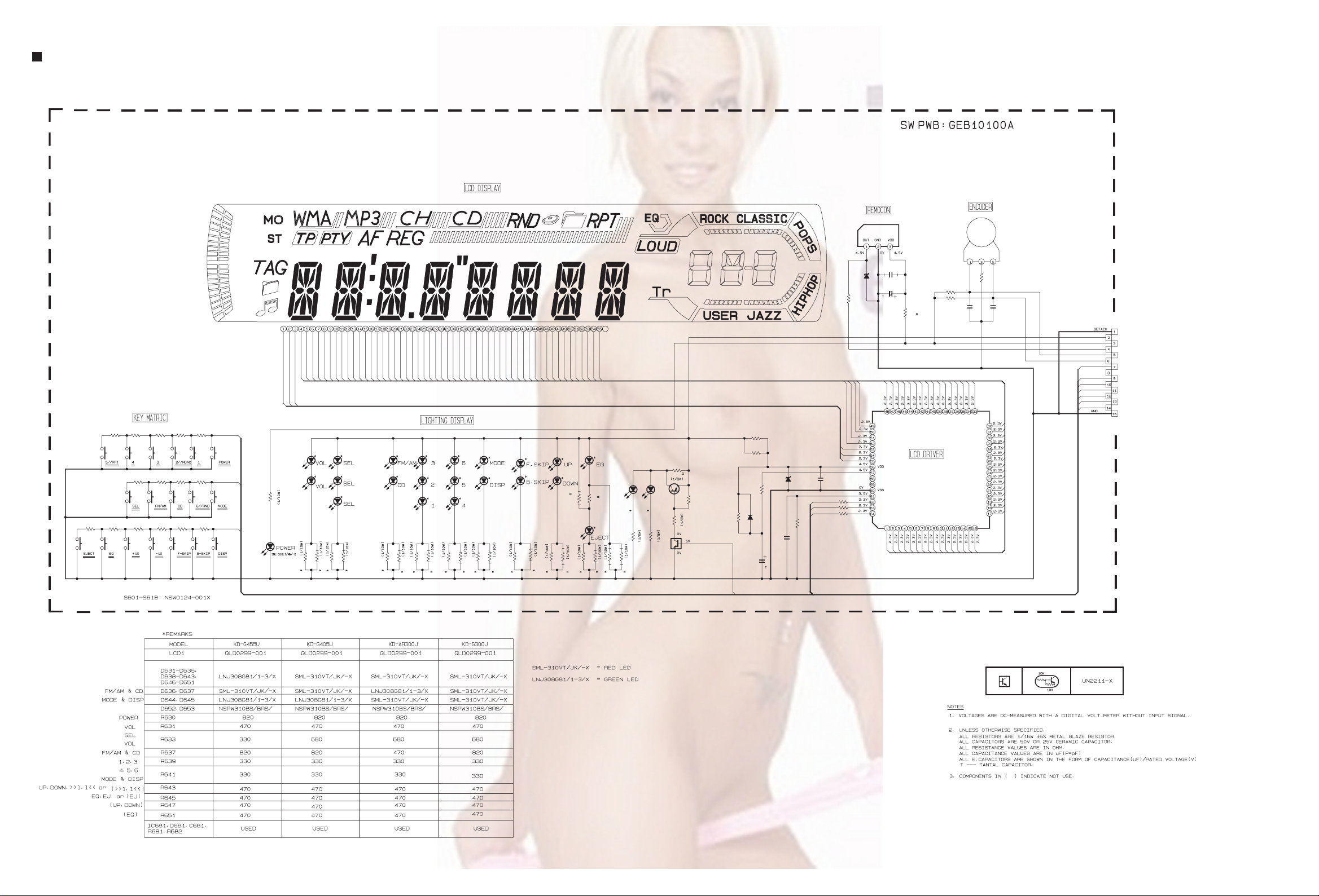
LCD & Key control section
S601
R614R615
S617S618
IC681
RPM7338-V4
C682
D681
0.012
UDZS6.2B-X
C681
10K
R682
LCD1
QLD0299-001
R601
R608
1.2K
S610
R612 R611
1.2K 820
R602R603R604
8201.2K1.8K
R607
820
KEY2
820
S605S604S603
S606
R606
KEY1
820
S607
S608S609
R610
KEY0
8201.8K2.7K3.9K
S612S613S614S615
R605
2.7K
S602
R609
1.8K
S611
R613
S616
R630
820
D630
COM1
COM2
COM3
S1
D631
R631
R632
R633
D632
D633
D634
R634
S14
S13
S12
S11
S10S9S8S7S6S5S4S3S2
S20
S19
S18
S17
S16
S15
D636
D637D635
R637
R638
R639
S26
S25
S24
S23
S22
S21
D640
D639
D638
R640
R641
S32
S31
S30
S29
S28
S27
D643
D642
D641
R643
R642
S38
S37
S36
S35
S34
S33
D644
D645
R645
R644
S44
S43
S42
S41
S40
S39
D647
D646
R646
R651
S50
S49
S48
S47
S46
S45
D649
D648
R652
S51
S52
R661
2.2K
R662
DIMOUT
180K
R663
10/6.3
C661
R664
2.2K
10K
D661
1SS355-X
C662
680p
D662
UDZS5.1B-X
R665
51K
LCDCE
LCDCL
LCDDA
C663
0.022
R666
R667
R668
10K
10K
10K
D650
0
0
R627
R626
D651
R647
R648
R653
R654
R649
D652
390
R650
D653
390
R670
470
Q670
2SB624/4/-X
R672
Q671
UN2211-X
R671
47K
1K
S49
S50
S51
S52
COM1
COM2
COM3
INH
OSC
CE
CLK
DATA
4.7/6.3
S48
S1
S45
S46
S47
S2
S3S4S5S6S7
R681
470
S44
PT6523LQ
S43
IC661
R687
47K
R688
47K
C686
0.022
S35
S36
S37
S40
S41
S42
S38
S39
S9
S8
S11
S10
S12
S13
S14
JS686
QSW0793-001
100
R686
C687
0.022
S33
S34
S32
S31
S30
S29
S28
S27
S26
S25
S24
S23
S22
S21
S20
S19
S18
S17
S16
S15
VMC0335-001
CJ601
REMOCON
DIMOUT
LCDCL
LCDDA
LCDCE
KEY0
KEY1
KEY2
ACC5V
ENC1
ENC2
10V
To CN701
(SHEET 1)
2-4
SHEET 3
Page 78

Printed circuit boards
Main board
Forward side
C412
C418
R404
C416
IC461
C461
C464
Q402
L404
C414
R424
C413
R529
R536
C523
C522
C462
X401
IC301
B353
R534
R532
R535
C531
C463
C901
B352
R528
R527
C527
D971
D972
C308
C355
Q543
R531
R533
IC401
L401
C411
R971
R972
D991 D992
C521
B351
C961
C307
IC521
C524
L402
C405
C317
C529
Q521
C971
C316
C421
R457
R458
C962
C963
C318
C532
D993
D996
CN501
C534
C525
R454
R453
C315
R481
C407
C542
L543
D994
C422
Q440
R558
R406
C566
CN901
C965
D998
C966
C964
C968
D995
C312
C301 C302
C481
C482
IC481
D481
C483
C440
R440
C570
L541
Q542
Q541
C543
C541
R414
R413
R412
D901
C967
D997
R509
R510
R511
C580
C590
C560
C562
C571
C544
R512
L544
R901
IC501
C514
C599
R551
R552
R553
C565
C311
R508
C559
C558
C902
C504
C581
C773
R507
R506
R505
C589
R584
C512
C505
R513
R592
C554
C553
R547
L901
R546
R583
R588
R594
C555
C919
C913
C909
R515
C506 C507
C583
C592
R595
R550
C557
R548
C545
D891
R549
C552
IC541
C881
R514
R516
R597
C594
C556
R598
C591
C551
C904
C515
R596
C572
C513
R586
R585
IC581
R518
C502
C593
C550
IC901
C905
Q891
D892
R891
Q501
R587
C584
C585
C582
C596
R545
C549
C548
C561
C510
R517
C501
Q502
C595
C908
C781
C785
R892
C503
D710
R544
R542
R541
R716
R715
R714
R593
R712
R710
R708
R707
R757
C709
C910
R783
Q783
R711
R706
C170
C193
R175
R719
R713
C710
R559
Q902
D782
C177 C178
R174
C180
R709
R717
C547
R910
C310
R785
R165
C168
R181
R182
R705
R163
R720
R704
Q901
Q782
C175
R756
R765
R703
R702
R976
R977
Q977
C166 C167
C772
C770
C914
C179
IC702
C358
R980
C169
X701
C359
R911
R904
R978
Q976
L701
R725
R164
X702
C784
R729
J801
R979
R726
C173
C907
R728
R755
C903
C851
R701
D244
D243
R162
C712
R771
C163
R248
C165
C162
C176
C174
R172
C713
IC701
R751
C707
R766
R242
R243
C164
C708
R753
R173
R750
R752
R331
C241
C172
C711
R739
R740
R247
R244
C192
R804
C243
C171
X31
R741
D331
R245
C191
IC161
C35
C37
Q331
R772
R805
R321
Q241
C161
D321
R171
C242
C40
C801
C43
C41
Q321
R161
R246
C32
IC31
C31
R802
R351
C244
C50
R44
R43
R37
C4
D351
D242
R241
Q31
C48
R36
D240
D241
R35
R806
C91
R33
Q351
R34
R809
R811
CN701
D341
R341
R1
C81
C33
L1
C1
R32
C34
R808
Q341
C810
J321
C360
R803
TU1
IC801
J1
R807
R801
R810
C7
C5
2-5
Page 79

Main board
J1
J321
C341
C321
R342
R343
C351
B359
D2
C8
D4
D5
R4
R5
C6
C3
C7
Q7
C45
C44
R38
C51
Q1
C49
R723
R51
D51
R52
C93
C83
C5
C94
C84
C46
C47
R9
C39
R2
R42
TU1
D1
C2
Q5
C38
C42
R10
CN701
R91
R353
Q6
D712
R352
Q10
C81
C91
C718
C33
L1
R6
R7
C717
R41
C1
C31
C244
C4
R39
C352
C242
D709
R81
C92
R92
D708
C192
C40
D707
C241
C716
R82
C82
D713
R323
R31
X31
D704
R322
R767
D705
C711
C191
C161
C43
R40
C171
C36
RD
R737
R738
R745
C163
R333
D706
R332
C162
C354
B356
R746
C172
TD
R735
C802
R736
D701
C173
C701
R734
D702
J801
D703
C784
C702
R749
C851
L701
R721
R763
C179
X702
C903
C907
C704
R754
R744
C169
R722
X701
R748
C914
R851
C852
C705
C194
R747
D852
R758
R743
D784
C782
C771
X1
C170
C703
C180
C356
B357
IC901
C912
Q784
C706
C915
C905
C310
RESET
Reverse side
C906
C193
C353
VDD
C911
Q781
C710
TP1
B355
C357
C910
D781
R776
R773
R778
R777
R775
R774
C503
R760
R759
VPP
C908
C781
D851
R852
C595
C546
R543
D902
C904
C881
C501
Q501
VSS
C597
C596
C561
C909
C585
C919
C572
C913
R591
C512
Q881
R881
R882
R903
R901
R582
C589
C599
R902
C902
C311
L901
D901
B351
R503
C580
R504
C590
R311
R302
R581
C302
R502
C570
R501
C543
C544
C541
R312
C568
C301
R539
R554
R555
R556
R557
C528
C312
R301
C481
R409
R408
R407
C566
C530
R530
R537
Q430
C525
R430
R423
R452
C404
C315
C422
VREF
C318
R402
R401
CN501
C529
C407
C317
C316
C891
RF
C533
C405
C307
Q521
C463
R451
C430
C304
C408
R455
R456
CN901
B352
C313
R415
C406
C403
C355
Q401
R462
R461
C411
R523
R524
R525
R526
C462
C308
C523
R416
C901
B353
R405
C416
C322
C314
C303
C325
C419
C420
C324
C319
IC301
C323
C320
X401
C415
2-6
Page 80

Front board
D630
JS686
R630
S606
D631
R601
D632
D633
S611
D634
D635
D636
S610
R608
R607
R609
S609
D637
LCD1
D638 D639
S604 S605
R602
R603
S603
Forward side
D640
R604
D641
R605
R626
IC681
R615
D651
S618
D652
D653
R611
D642
S601 S602
S608
D643
R606
D644
S607
R610
D645
S612
S613
D646
D647
S614
R654
S615
R651
R652
D650
D648
S617
D649
R612
S616
R614
R653
R613
R672
IC681
Q671
Q670
R671
R646
C681
D652
C682
R645
D653
R648
R650
R670
R649
R647
D681
R643
R644
R681
R682
R663
D661
C661
R661
CJ601
R662
R664
C662
R665
R667
R668
R666
D662
Reverse side
IC661
C663
R641
R642
R637
R638
R639
R640
R634
JS686
R633
R688
C687
R686
C686
D629
R687
R631
R632
2-7
Page 81

VICTOR COMPANY OF JAPAN, LIMITED
AV & MULTIMEDIA COMPANY MOBILE ENTERTAINMENT CATEGORY 10-1,1chome,Ohwatari-machi,Maebashi-city,371-8543,Japan
(No.MA036SCH)
Printed in Japan
WPC
Page 82

PARTS LIST
[ KD-G300 ]
[ KD-AR300 ]
* All printed circuit boards and its assemblies are not available as service parts.
Area suffix
J -------------- Northern America
- Contents -
Exploded view of general assembly and parts list (Block No.M1)
CD mechanism assembly and parts list (Block No.MB)
Electrical parts list (Block No.01,02)
Packing materials and accessories parts list (Block No.M3)
No. MA036 3-1
3- 2
3- 4
3- 6
3-11
Page 83

Exploded view of general assembly and parts list
Block No.
9
50
53
58
51
9
52
9
49
48
54
C
A
1
55
56
A
8
14
15
Main board
8
18
13
11
16
39
17
5
38
4
M
45
42
47
41
M
1
M
43
44
46
LCD1
39
13
2
B
3
7
10
C
7
6
12
Front
board
31
6
29
27
23
26
28
6
21
32
57
33
30
35
22
25
24
34
37
36
40
19
20
3-2
Page 84

General assembly
Block No. [M][1][M][M]
Symbol No.
1 GE10043-210A TOP CHASSIS
2 GE40135-001A EARTH PLATE
3 GE30938-003A SIDE PANEL
4 GE30393-002A BOTTOM COVER
5 FSMA3004-203 INSULATOR
6 QYSDST2604Z SCREW 2.6mm x 4mm(x3)
7 FSKZ4005-001 SCREW (x2)
8 QYSDST2606Z SCREW 2.6mm x 6mm(x2)
9 QYSDST2604Z SCREW 2.6mm x 4mm(x3)
10 QYSDST2610Z SCREW 2.6mm x 10mm
11 GE10079-001A FRONT CHASSIS
12 FSYH4036-098 SHEET
13 QYSDST2004M MINI SCREW 2mm x 4mm(x2)
14 GE31033-001A LOCK LEVER
15 FSKW4005-003 TORSION SPRING
16 GE40202-005A
17 GE31034-001A RLS KNOB
18 GE40156-001A BLIND
19 GE10077-003A FRONT PANEL
19 GE10077-001A FRONT PANEL G300J
20 GE31031-030A FINDER ASSY
20 GE31031-024A FINDER ASSY G300J
21 GE31027-001A POWER BUTTON
22 GE31038-001A VOLUME KNOB
23 GE40218-002A SHEET
24 GE31039-004A SEL BUTTON
24 GE31039-003A SEL BUTTON G300J
25 FSYH4036-053 SHEET
26 GE31040-001A RIM LENS
27 FSYH4036-069 SHEET
28 GE31181-002A D.FUNC BTN
28 GE31029-001A D.FUNC BTN G300J
29 FSYH4036-069 SHEET
30 GE20161-002A PRESET BUTTON
30 GE20161-001A PRESET BUTTON G300J
31 FSYH4036-069 SHEET (x2)
32 GE31024-003A UP/DOWN BTN
32 GE31024-001A UP/DOWN BTN G300J
33 GE31028-003A SSM BTN
34 GE31025-002A SEARCH BTN
34 GE31025-001A SEARCH BTN G300J
35 GE31026-001A EJECT BUTTON
36 GE31032-003A DETACH BTN
36 GE31032-002A DETACH BTN G300J
37 GE40202-003A
38 GE10078-001A REAR COVER
39 VKZ4777-001 MINI SCREW (x4)
40 GE31021-001A LCD CASE
41 GE31022-002A LCD LENS
42 GE31023-001A LENS CASE
43 GE40199-001A LIGHTING SHEET
44 GE40199-002A LIGHTING SHEET
45 GE31095-003A NAME PLATE
45 GE31231-002A NAME PLATE G300J
46 QLD0299-001 LCD MODULE
47 QNZ0443-001 LCD CONNECTOR
48 QMFZ047-150-T FUSE 15A
49 GE30912-006A REAR BRACKET
49 GE30912-008A REAR BRACKET G300J
50 QYSDST2606Z SCREW 2.6mm x 6mm
51 QYSDST2606Z SCREW 2.6mm x 6mm
52 QYSDSF2606Z SCREW 2.6mm x 6mm(x2)
53 QYSDSF2606Z SCREW 2.6mm x 6mm
54 GE40172-004A IC BRACKET
Part No. Part Name Description Local
COMPRESSION SPRING
COMPRESSION
SPRING
AR30
0J
AR30
0J
AR30
0J
AR30
0J
AR30
0J
AR30
0J
AR30
0J
AR30
0J
AR30
0J
AR30
0J
Symbol No.
55 GE40103-003A REG BRACKET
56 GE40107-002A HEAT SINK
57 GE30854-001A LED HOLDER
58 QYSDST2606Z SCREW 2.6mm x 6mm
Part No. Part Name Description Local
AR30
0J
3-3
Page 85
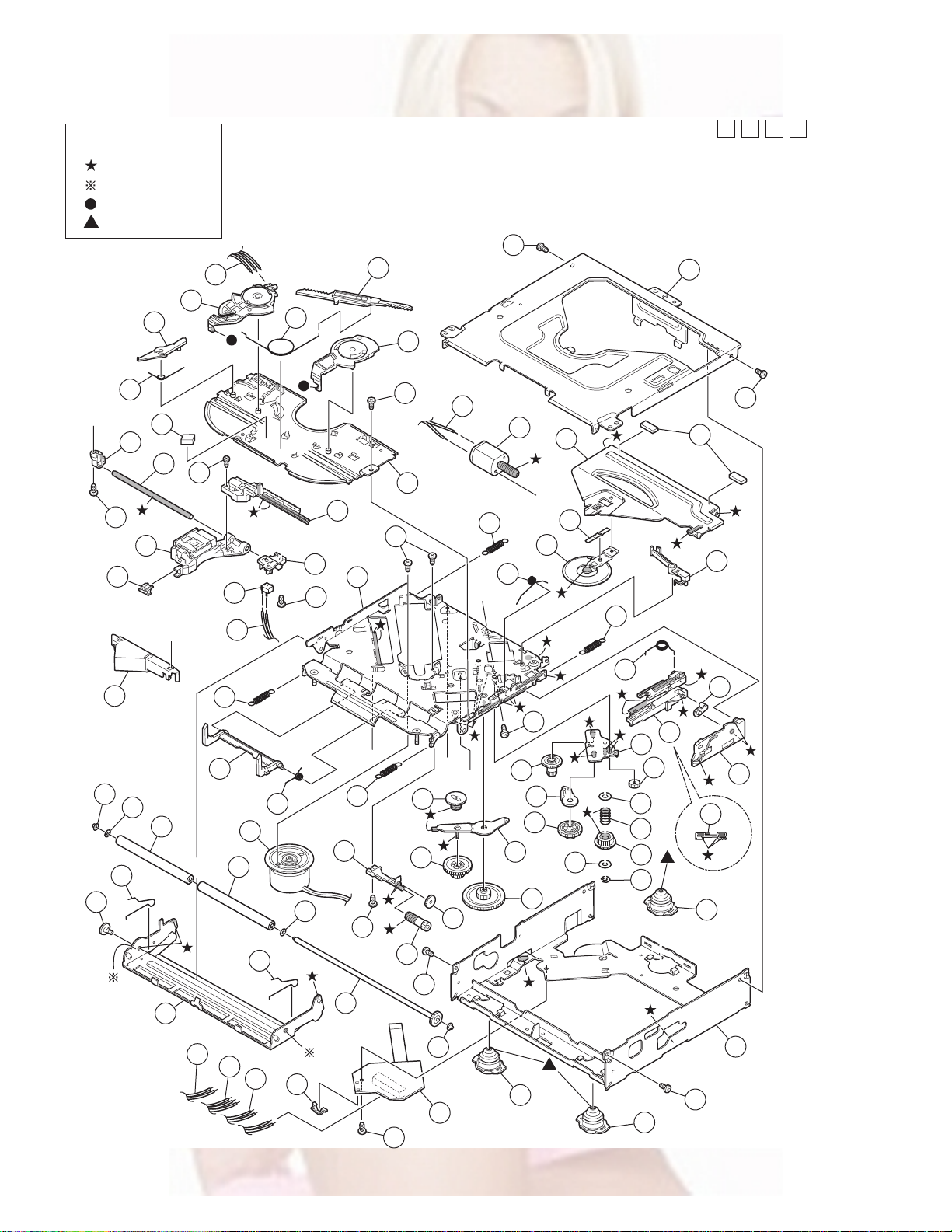
CD mechanism assembly and parts list
Grease
TNG-87
GP-501MK
CFD-005Z
GP-501A
31
C
22
112
24
61
26
36
29
Block No.
M
M
B
M
TN-2001-1011
111
74
72
35
116
34
33
111
25
73
85
15
A
19
B
21
62
D
75
112
114
11
38
30
A
23
13
32
2
111
37
27
101
93
76
94
122
100
84
73
95
38
74
100
a
14
75
94
96
77
123
97
81
32
a
113
99
28
115
D
111
91
90
89
111
93
71
C
B
92
82
18
20
87
125
88
3
12
121
16
17
124
83
86
111
3
98
83
4
1
3-4
Page 86

CD mechanism
Block No. [M][B][M][M]
Symbol No.
1 30320101T FRAME
2 30320102T TOP COVER
3 30320115T DANPER F
4 30320116T DANPER R
11 303205505T CHASSIS RIVET
12 303205503T CHANGE P. RVT A
13 303205301T CLAMPER ASS'Y
14 303205302T SPINDLE MOTOR A
15 30320502T CLAMPER ARM
16 30320503T CHANGE GEAR SPG
17 30320505T CHANGE GEAR 2
18 30320506T FEED GEAR
19 30320507T FEED RACK
20 30320509T CHANGE LOCK RAR
21 30320510T FEED SW HOLDER
22 30320511T PU SHAFT HOLDER
23 30320513T CLAMPER SUB SPG
24 30320514T FD SUB HOLDER
25 30320518T TOP PLATE
26 30320519T SELECT LOCK ARM
27 30320520T TRIGGER ARM
28 30320521T SLIDE HOOK
29 30320522T PU SHAFT
30 30320525T CLAMPER ARM SPG
31 30320526T SELECT L ARM SP
32 30320538T SUSPENSION SP R
33 30320529T SELECT ARM R
34 30320530T LINK PLATE
35 30320531T LINK PLATE SPG
36 30320523T CUSHION F
37 30320524T CUSHION R
38 30320539T SUSPENSION SP L
61 69011614T PICKUP OPT-725
62 64180406T DET SW ESE22
71 303210301T CONN PWB ASS'Y
72 30321002T MODE SW
73 30321003T LOAD MOTOR WIRE
74 30321005T MODE SW WIRE
75 30321009T SL WIRE
76 30321011T WIRE HOLDER
77 19501403T WIRE CLUMPER
81 303211301T ROLLER SHAFT AS
82 303211501T L GEAR PLAT E RV
83 303211302T LOADING PLA TE A
84 303211502T LOCK ARM RV ASS
85 303211303T L/F MOTOR ASS'Y
86 30321101T LOADING GEAR 1
87 30321102T LOADING GEAR 2
88 30321103T LOADING GEAR 3
89 30321104T LOADING GEAR 4
90 30321105T LOADING GEAR 5
91 30321106T LOADING GEAR 6
92 30321107T LOADING GEAR 7
93 30321111T ROLLER GUIDE
94 30321114T ROLLER GUIDE SP
95 30321116T DISC STOPPER AR
96 30321117T DISC ST ARM SPG
97 30321118T LD GEAR BRACKET
98 30321125T L SIDE PLATE
99 30321131T LOAD PLATE SPG
100 30321133T LDG ROLLER
101 18211223T COLLAR SCREW
111 9P0420031T SCREW
112 9P0420041T TAP.SCREW
113 9B0320041T SCREW
114 9C0117183T SCREW
115 9C0120203T SCREW
116 9C0317503T SCREW
121 9W0130170T PW 3.5X8X0.3
122 9W0513060T HL WASHER
123 9W0710070T L WASHER
124 9E0100152T E RING
125 9W0113020T PW 2.1X4X0.13
Part No. Part Name Description Local
3-5
Page 87

Electrical parts list
Main board
Block No. [0][1][0][0]
Symbol No.
IC31 TB2118F-X PLL IC
IC161 TEA6320T-X IC
IC301 LA47515 IC
IC401 TC94A34FG-002 IC
IC461 NJU7772F15-X IC
IC481 AK4385VT-X IC
IC501 LA6242H-X IC
IC521 TA2157FN-X RF AMP IC
IC541 TC94A14FA CD LSI IC
IC581 NJM4565M-WE IC
IC701 UPD784217AGC238 IC
IC702 IC-PST3433U-X IC
IC801 HD74HC126FP-X IC
IC901 AN80T07 IC
Q1 2SD601A/QR/-X TRANSISTOR
Q5 2SB709A/R/-X TRANSISTOR
Q6 2SB624/4/-X TRANSISTOR
Q7 UN2211-X TRANSISTOR
Q10 UN2211-X TRANSISTOR
Q31 UN2211-X TRANSISTOR
Q341 2SD1781K/QR/-X TRANSISTOR
Q351 2SD1781K/QR/-X TRANSISTOR
Q401 2SB624/4/-X TRANSISTOR
Q402 UN2211-X TRANSISTOR
Q430 UN2211-X TRANSISTOR
Q440 UN2211-X TRANSISTOR
Q501 2SB1322/RS/-T TRANSISTOR
Q502 2SB1132/QR/-W TRANSISTOR
Q521 2SB1241/QR/-T TRANSISTOR
Q541 UN2111-X TRANSISTOR
Q542 UN2211-X TRANSISTOR
Q543 UN2111-X TRANSISTOR
Q781 UN2111-X TRANSISTOR
Q782 UN2211-X TRANSISTOR
Q784 UN2111-X TRANSISTOR
Q976 UN2211-X TRANSISTOR
Q977 2SB709A/QR/-X TRANSISTOR
D1 1SS355-X SI DIODE
D2 1SS355-X SI DIODE
D4 1SS355-X SI DIODE
D5 1SS355-X SI DIODE
D341 1SS355-X SI DIODE
D351 1SS355-X SI DIODE
D481 UDZS5.1B-X Z DIODE
D701 UDZS6.2B-X Z DIODE
D702 UDZS6.2B-X Z DIODE
D703 UDZS6.2B-X Z DIODE
D704 UDZS6.2B-X Z DIODE
D705 UDZS6.2B-X Z DIODE
D706 UDZS6.2B-X Z DIODE
D707 UDZS6.2B-X Z DIODE
D708 UDZS6.2B-X Z DIODE
D709 UDZS6.2B-X Z DIODE
D710 1SS355-X SI DIODE
D712 UDZS6.2B-X Z DIODE
D713 UDZS6.2B-X Z DIODE
D781 1SS355-X SI DIODE
D782 1SS355-X SI DIODE
D784 UDZS11B-X Z DIODE
D901 1N5401-TU-15 DIODE
D902 1SS355-X SI DIODE
D971 RB160M-30-X SB DIODE
D972 RB160M-30-X SB DIODE
C1 QEKJ1CM-226Z E CAPACITOR 22uF 16V M
C2 NCB31EK-473X C CAPACITOR 0.047uF 25V K
C3 NCB31EK-103X C CAPACITOR 0.01uF 25V K
C4 QEKJ1AM-227Z E CAPACITOR 220uF 10V M
C5 QERF1HM-104Z E CAPACITOR 0.1uF 50V M
Part No. Part Name Description Local
AR30
0J
Symbol No.
C6 NCB31HK-103X C CAPACITOR 0.01uF 50V K
C7 QEKJ1CM-226Z E CAPACITOR 22uF 16V M
C31 QEKJ1AM-107Z E CAPACITOR 100uF 10V M
C32 NDC31HJ-470X C CAPACITOR 47pF 50V J
C33 QEKJ0JM-476Z E CAPACITOR 47uF 6.3V M
C34 NCB31EK-473X C CAPACITOR 0.047uF 25V K
C35 NDC31HJ-100X C CAPACITOR 10pF 50V J
C36 NDC31HJ-7R0X C CAPACITOR 7pF 50V J
C37 NDC31HJ-100X C CAPACITOR 10pF 50V J
C38 NCB31HK-102X C CAPACITOR 1000pF 50V K
C39 NCB31HK-102X C CAPACITOR 1000pF 50V K
C40 QEKJ1CM-106Z E CAPACITOR 10uF 16V M
C41 NCB31EK-473X C CAPACITOR 0.047uF 25V K
C42 NCB31HK-103X C CAPACITOR 0.01uF 50V K
C43 QFV61HJ-473Z MF CAPACITOR 0.047uF 50V J
C44 NCB31HK-103X C CAPACITOR 0.01uF 50V K
C45 NCB31HK-272X C CAPACITOR 2700pF 50V K
C46 NCB31HK-103X C CAPACITOR 0.01uF 50V K
C47 NCB31HK-103X C CAPACITOR 0.01uF 50V K
C48 NCB31EK-473X C CAPACITOR 0.047uF 25V K
C49 NCB31HK-102X C CAPACITOR 1000pF 50V K
C50 NDC31HJ-101X C CAPACITOR 100pF 50V J
C51 NDC31HJ-331X C CAPACITOR 330pF 50V J
C81 QEKJ1HM-105Z E CAPACITOR 1uF 50V M
C83 NCB31HK-153X C CAPACITOR 0.015uF 50V K
C84 NCB31HK-153X C CAPACITOR 0.015uF 50V K
C91 QEKJ1HM-105Z E CAPACITOR 1uF 50V M
C93 NCB31HK-153X C CAPACITOR 0.015uF 50V K
C94 NCB31HK-153X C CAPACITOR 0.015uF 50V K
C161 QEKJ1HM-105Z E CAPACITOR 1uF 50V M
C162 QEKJ1HM-105Z E CAPACITOR 1uF 50V M
C163 QEKJ1HM-105Z E CAPACITOR 1uF 50V M
C164 NCB31HK-822X C CAPACITOR 8200pF 50V K
C165 NCB31AK-224X C CAPACITOR 0.22uF 10V K
C166 NCB21CK-224X C CAPACITOR 0.22uF 16V K
C167 NCB31EK-333X C CAPACITOR 0.033uF 25V K
C168 NCB31HK-562X C CAPACITOR 5600pF 50V K
C169 QEKJ1EM-475Z E CAPAC ITOR 4.7uF 25V M
C170 QEKJ1EM-475Z E CAPAC ITOR 4.7uF 25V M
C171 QEKJ1HM-105Z E CAPACITOR 1uF 50V M
C172 QEKJ1HM-105Z E CAPACITOR 1uF 50V M
C173 QEKJ1HM-105Z E CAPACITOR 1uF 50V M
C174 NCB31HK-822X C CAPACITOR 8200pF 50V K
C175 NCB31AK-224X C CAPACITOR 0.22uF 10V K
C176 NCB21CK-224X C CAPACITOR 0.22uF 16V K
C177 NCB31EK-333X C CAPACITOR 0.033uF 25V K
C178 NCB31HK-562X C CAPACITOR 5600pF 50V K
C179 QEKJ1EM-475Z E CAPAC ITOR 4.7uF 25V M
C180 QEKJ1EM-475Z E CAPAC ITOR 4.7uF 25V M
C191 QEKJ1CM-476Z E CAPACITOR 47uF 16V M
C192 QEKJ1AM-107Z E CAPACITOR 100uF 10V M
C193 QEKJ1AM-107Z E CAPACITOR 100uF 10V M
C194 NCB31EK-823X C CAPACITOR 0.082uF 25V K
C301 QFVD1HJ-474Z MF CAPACITOR 0.47uF 50V J
C302 QFVD1HJ-474Z MF CAPACITOR 0.47uF 50V J
C303 NCS31HJ-391X C CAPACITOR 390pF 50V J
C304 NCS31HJ-391X C CAPACITOR 390pF 50V J
C307 QEKJ1HM-105Z E CAPACITOR 1uF 50V M
C308 QEKJ1HM-105Z E CAPACITOR 1uF 50V M
C311 QFVD1HJ-474Z MF CAPACITOR 0.47uF 50V J
C312 QFVD1HJ-474Z MF CAPACITOR 0.47uF 50V J
C313 NCS31HJ-391X C CAPACITOR 390pF 50V J
C314 NCS31HJ-391X C CAPACITOR 390pF 50V J
C315 QEKJ1HM-225Z E CAPACITOR 2.2uF 50V M
C316 QEKJ1EM-475Z E CAPAC ITOR 4.7uF 25V M
C317 QEKJ1CM-476Z E CAPACITOR 47uF 16V M
C318 QEKJ1CM-226Z E CAPACITOR 22uF 16V M
C319 NCB31EK-223X C CAPACITOR 0.022uF 25V K
C320 NCB31EK-223X C CAPACITOR 0.022uF 25V K
C322 NCB31EK-104X C CAPACITOR 0.1uF 25V K
C323 NCB31EK-104X C CAPACITOR 0.1uF 25V K
C324 NCB31EK-104X C CAPACITOR 0.1uF 25V K
Part No. Part Name Description Local
AR30
0J
AR30
0J
3-6
Page 88

Symbol No.
Part No. Part Name Description Local
Symbol No.
Part No. Part Name Description Local
C325 NCB31EK-104X C CAPACITOR 0.1uF 25V K
C341 NCB31EK-473X C CAPACITOR 0.047uF 25V K
C355 QEKJ1CM-107Z E CAPACITOR 100uF 16V M
C357 NCB31EK-473X C CAPACITOR 0.047uF 25V K
C403 NCB31HK-103X C CAPACITOR 0.01uF 50V K
C404 NCB31HK-103X C CAPACITOR 0.01uF 50V K
C405 QERF1HM-105Z E CAPACITOR 1uF 50V M
C406 NCB31EK-103X C CAPACITOR 0.01uF 25V K
C407 QERF1AM-107Z E CAPACITOR 100uF 10V M
C408 NCB31HK-103X C CAPACITOR 0.01uF 50V K
C411 QEKJ1AM-107Z E CAPACITOR 100uF 10V M
C412 NCB31HK-103X C CAPACITOR 0.01uF 50V K
C413 NCB31EK-104X C CAPACITOR 0.1uF 25V K
C414 NCB31HK-222X C CAPACITOR 2200pF 50V K
C415 NCB31EK-104X C CAPACITOR 0.1uF 25V K
C416 QEKJ1AM-107Z E CAPACITOR 100uF 10V M
C418 NCB31HK-103X C CAPACITOR 0.01uF 50V K
C419 NDC31HJ-7R0X C CAPACITOR 7pF 50V J
C420 NDC31HJ-8R0X C CAPACITOR 8pF 50V J
C421 NCB31HK-103X C CAPACITOR 0.01uF 50V K
C422 QEKJ1AM-107Z E CAPACITOR 100uF 10V M
C430 NCB31HK-103X C CAPACITOR 0.01uF 50V K
C440 NCB31HK-103X C CAPACITOR 0.01uF 50V K
C461 NCB31EK-104X C CAPACITOR 0.1uF 25V K
C462 QEKJ0JM-107Z E CAPACITOR 100uF 6.3V M
C463 QEKJ0JM-107Z E CAPACITOR 100uF 6.3V M
C464 NCB31EK-104X C CAPACITOR 0.1uF 25V K
C481 QERF1CM-476Z E CAPACITOR 47uF 16V M
C482 NCB31EK-104X C CAPACITOR 0.1uF 25V K
C483 NCB31EK-104X C CAPACITOR 0.1uF 25V K
C501 QERF1AM-476Z E CAPACITOR 47uF 10V M
C502 NCB31HK-103X C CAPACITOR 0.01uF 50V K
C503 QEKJ1AM-107Z E CAPACITOR 100uF 10V M
C504 NCB31EK-473X C CAPACITOR 0.047uF 25V K
C505 NCB31EK-473X C CAPACITOR 0.047uF 25V K
C506 NCB31EK-473X C CAPACITOR 0.047uF 25V K
C507 NCB31EK-473X C CAPACITOR 0.047uF 25V K
C510 NCB31EK-103X C CAPACITOR 0.01uF 25V K
C512 QERF1CM-476Z E CAPACITOR 47uF 16V M
C513 NCB31EK-103X C CAPACITOR 0.01uF 25V K
C514 NCB31EK-103X C CAPACITOR 0.01uF 25V K
C521 NCB31HK-103X C CAPACITOR 0.01uF 50V K
C522 NCB31HK-103X C CAPACITOR 0.01uF 50V K
C523 QEKJ1AM-107Z E CAPACITOR 100uF 10V M
C524 NCB31HK-103X C CAPACITOR 0.01uF 50V K
C525 QEKJ1AM-107Z E CAPACITOR 100uF 10V M
C527 NCB31HK-682X C CAPACITOR 6800pF 50V K
C528 NCB31HK-103X C CAPACITOR 0.01uF 50V K
C529 QEKJ1AM-107Z E CAPACITOR 100uF 10V M
C530 NCB31EK-104X C CAPACITOR 0.1uF 25V K
C531 NCB31EK-104X C CAPACITOR 0.1uF 25V K
C532 NDC31HJ-680X C CAPACITOR 68pF 50V J
C533 NCB31HK-103X C CAPACITOR 0.01uF 50V K
C534 NDC31HJ-5R0X C CAPACITOR 5pF 50V J
C541 QEKJ1AM-107Z E CAPACITOR 100uF 10V M
C542 NCB31HK-103X C CAPACITOR 0.01uF 50V K
C543 QEKJ1HM-105Z E CAPACITOR 1uF 50V M
C544 QEKJ1AM-107Z E CAPACITOR 100uF 10V M
C545 NCB31HK-103X C CAPACITOR 0.01uF 50V K
C546 NDC31HJ-470X C CAPACITOR 47pF 50V J
C547 NCB31HK-153X C CAPACITOR 0.015uF 50V K
C548 NCB31HK-103X C CAPACITOR 0.01uF 50V K
C549 NCB31HK-272X C CAPACITOR 2700pF 50V K
C550 NCB31HK-103X C CAPACITOR 0.01uF 50V K
C551 NCB31EK-333X C CAPACITOR 0.033uF 25V K
C552 NCB31EK-333X C CAPACITOR 0.033uF 25V K
C553 NCB31EK-473X C CAPACITOR 0.047uF 25V K
C554 NCB31EK-473X C CAPACITOR 0.047uF 25V K
C555 NCB31EK-473X C CAPACITOR 0.047uF 25V K
C556 NCB31HK-471X C CAPACITOR 470pF 50V K
C557 NCB31HK-471X C CAPACITOR 470pF 50V K
C558 NCB31EK-473X C CAPACITOR 0.047uF 25V K
C559 NCB31EK-473X C CAPACITOR 0.047uF 25V K
C560 NCB31HK-103X C CAPACITOR 0.01uF 50V K
C561 QEKJ1AM-107Z E CAPACITOR 100uF 10V M
C562 NCB31HK-103X C CAPACITOR 0.01uF 50V K
C565 NCB31HK-103X C CAPACITOR 0.01uF 50V K
C566 QEKJ1AM-107Z E CAPACITOR 100uF 10V M
C568 NCB31EK-104X C CAPACITOR 0.1uF 25V K
C570 QERF1AM-476Z E CAPACITOR 47uF 10V M
C571 NCB31HK-103X C CAPACITOR 0.01uF 50V K
C572 QERF1AM-107Z E CAPACITOR 100uF 10V M
C580 QEKJ1EM-475Z E CAPACITOR 4.7uF 25V M
C581 NCB31HK-332X C CAPACITOR 3300pF 50V K
C582 NDC31HJ-271X C CAPACITOR 270pF 50V J
C583 NDC31HJ-271X C CAPACITOR 270pF 50V J
C584 NCB31EK-104X C CAPACITOR 0.1uF 25V K
C585 QEKJ0JM-476Z E CAPACITOR 47uF 6.3V M
C589 QEKJ1EM-475Z E CAPACITOR 4.7uF 25V M
C590 QEKJ1EM-475Z E CAPACITOR 4.7uF 25V M
C591 NCB31HK-332X C CAPACITOR 3300pF 50V K
C592 NDC31HJ-271X C CAPACITOR 270pF 50V J
C593 NDC31HJ-271X C CAPACITOR 270pF 50V J
C594 NCB31EK-104X C CAPACITOR 0.1uF 25V K
C595 QEKJ0JM-476Z E CAPACITOR 47uF 6.3V M
C596 QEKJ1AM-107Z E CAPACITOR 100uF 10V M
C597 NCB31HK-103X C CAPACITOR 0.01uF 50V K
C599 QEKJ1EM-475Z E CAPACITOR 4.7uF 25V M
C600 QCBB1HK-103Y C CAPACITOR 0.01uF 50V K
C701 NDC31HJ-220X C CAPACITOR 22pF 50V J
C702 NDC31HJ-270X C CAPACITOR 27pF 50V J
C703 NDC31HJ-270X C CAPACITOR 27pF 50V J
C704 NDC31HJ-8R0X C CAPACITOR 8pF 50V J
C705 NCB31EK-473X C CAPACITOR 0.047uF 25V K
C706 NCB31EK-473X C CAPACITOR 0.047uF 25V K
C707 NCB31EK-104X C CAPACITOR 0.1uF 25V K
C708 NCB31EK-473X C CAPACITOR 0.047uF 25V K
C709 NCB31EK-104X C CAPACITOR 0.1uF 25V K
C710 QERF0JM-476Z E CAPA CITOR 47uF 6.3V M
C711 QEKJ0JM-227Z E CAPACITOR 220uF 6.3V M
C712 NCB31HK-103X C CAPACITOR 0.01uF 50V K
C713 NCB31EK-104X C CAPACITOR 0.1uF 25V K
C716 NCB31EK-104X C CAPACITOR 0.1uF 25V K
C717 NCB31EK-104X C CAPACITOR 0.1uF 25V K
C718 NCB31EK-104X C CAPACITOR 0.1uF 25V K
C770 NCB31EK-473X C CAPACITOR 0.047uF 25V K
C771 NCB31EK-473X C CAPACITOR 0.047uF 25V K
C772 NCB31EK-104X C CAPACITOR 0.1uF 25V K
C781 QEKJ0JM-476Z E CAPACITOR 47uF 6.3V M
C782 NCB31EK-823X C CAPACITOR 0.082uF 25V K
C784 QEKJ1CM-107Z E CAPACITOR 100uF 16V M
C801 NCB31EK-473X C CAPACITOR 0.047uF 25V K
C802 NCB31HK-103X C CAPACITOR 0.01uF 50V K
C901 QEZ0622-338 E CAPACITOR 3300uF
C902 QEKJ1HM-225Z E CAPACITOR 2.2uF 50V M
C903 QEKJ1CM-226Z E CAPACITOR 22uF 16V M
C904 QEKJ1CM-106Z E CAPACITOR 10uF 16V M
C905 QEKJ1CM-476Z E CAPACITOR 47uF 16V M
C906 NCB31HK-103X C CAPACITOR 0.01uF 50V K
C907 QEKJ1AM-227Z E CAPACITOR 220uF 10V M
C908 QEKJ1AM-227Z E CAPACITOR 220uF 10V M
C909 QEKJ1AM-227Z E CAPACITOR 220uF 10V M
C910 QEKJ1CM-476Z E CAPACITOR 47uF 16V M
C911 NCB31CK-104X C CAPACITOR 0.1uF 16V K
C912 NCB31HK-103X C CAPACITOR 0.01uF 50V K
C913 QEKJ1CM-106Z E CAPACITOR 10uF 16V M
C914 QEKJ1CM-107Z E CAPACITOR 100uF 16V M
C915 NCB31CK-104X C CAPACITOR 0.1uF 16V K
C919 QEKJ1CM-106Z E CAPACITOR 10uF 16V M
C961 NDC31HJ-101X C CAPACITOR 100pF 50V J
C962 NDC31HJ-101X C CAPACITOR 100pF 50V J
C963 NDC31HJ-101X C CAPACITOR 100pF 50V J
C964 NDC31HJ-101X C CAPACITOR 100pF 50V J
C965 NDC31HJ-101X C CAPACITOR 100pF 50V J
C966 NDC31HJ-101X C CAPACITOR 100pF 50V J
C967 NDC31HJ-101X C CAPACITOR 100pF 50V J
C968 NDC31HJ-101X C CAPACITOR 100pF 50V J
C971 NCB31EK-104X C CAPACITOR 0.1uF 25V K
R1 NRS181J-120X MG RESISTOR 12Ω 1/8W J
R2 NRSA63J-473X MG RESISTOR 47kΩ 1/16W J
R4 NRSA63J-332X MG RESISTOR 3.3k
R5 NRSA63J-473X MG RESISTOR 47k
R6 NRSA63J-473X MG RESISTOR 47kΩ 1/16W J
Ω
1/16W J
Ω
1/16W J
AR30
0J
AR30
0J
3-7
Page 89

Symbol No.
Part No. Part Name Description Local
Symbol No.
Part No. Part Name Description Local
R7 NRSA63J-472X MG RESISTOR 4.7kΩ 1/16W J
R9 NRSA63J-470X MG RESISTOR 47Ω 1/16W J
R10 NRSA63J-103X MG RESISTOR 10kΩ 1/16W J
R31 NRS181J-100X MG RESISTOR 10Ω 1/8W J
R32 NRSA63J-622X MG RESISTOR 6.2kΩ 1/16W J
R33 NRSA63J-103X MG RESISTOR 10k
R34 NRSA63J-222X MG RESISTOR 2.2k
R35 NRSA63J-222X MG RESISTOR 2.2kΩ 1/16W J
R36 NRSA63J-222X MG RESISTOR 2.2kΩ 1/16W J
R37 NRSA63J-222X MG RESISTOR 2.2kΩ 1/16W J
R38 NRSA63J-101X MG RESISTOR 100Ω 1/16W J
R39 NRSA63J-0R0X MG RESISTOR 0Ω 1/16W J
R40 NRSA63J-393X MG RESISTOR 39kΩ 1/16W J
R41 NRSA63J-103X MG RESISTOR 10kΩ 1/16W J
R42 NRS181J-100X MG RESISTOR 10Ω 1/8W J
R43 NRSA63J-471X MG RESISTOR 470Ω 1/16W J
R44 NRSA63J-221X MG RESISTOR 220Ω 1/16W J
R51 NRSA63J-273X MG RESISTOR 27kΩ 1/16W J
R52 NRSA63J-0R0X MG RESISTOR 0Ω 1/16W J
R81 NRSA63J-222X MG RESISTOR 2.2kΩ 1/16W J
R82 NRSA63J-392X MG RESISTOR 3.9k
R91 NRSA63J-222X MG RESISTOR 2.2k
R92 NRSA63J-392X MG RESISTOR 3.9kΩ 1/16W J
R162 NRSA63J-223X MG RESISTOR 22kΩ 1/16W J
R163 NRSA63J-222X MG RESISTOR 2.2kΩ 1/16W J
R164 NRSA63J-473X MG RESISTOR 47kΩ 1/16W J
R165 NRSA63J-473X MG RESISTOR 47kΩ 1/16W J
R172 NRSA63J-223X MG RESISTOR 22kΩ 1/16W J
R173 NRSA63J-222X MG RESISTOR 2.2kΩ 1/16W J
R174 NRSA63J-473X MG RESISTOR 47kΩ 1/16W J
R175 NRSA63J-473X MG RESISTOR 47kΩ 1/16W J
R181 NRSA63J-271X MG RESISTOR 270Ω 1/16W J
R182 NRSA63J-271X MG RESISTOR 270Ω 1/16W J
R301 NRSA63J-273X MG RESISTOR 27kΩ 1/16W J
R302 NRSA63J-273X MG RESISTOR 27kΩ 1/16W J
R311 NRSA63J-273X MG RESISTOR 27kΩ 1/16W J
R312 NRSA63J-273X MG RESISTOR 27kΩ 1/16W J
R341 NRSA63J-222X MG RESISTOR 2.2kΩ 1/16W J
R342 NRSA63J-821X MG RESISTOR 820Ω 1/16W J
R343 NRSA63J-101X MG RESISTOR 100Ω 1/16W J
R351 NRSA63J-222X MG RESISTOR 2.2kΩ 1/16W J
R352 NRSA63J-821X MG RESISTOR 820Ω 1/16W J
R353 NRSA63J-101X MG RESISTOR 100Ω 1/16W J
R402 NRSA63J-101X MG RESISTOR 100Ω 1/16W J
R404 NRSA63J-103X MG RESISTOR 10kΩ 1/16W J
R405 NRSA63J-225X MG RESISTOR 2.2MΩ 1/16W J
R406 NRSA63J-470X MG RESISTOR 47Ω 1/16W J
R407 NRSA63J-222X MG RESISTOR 2.2kΩ 1/16W J
R408 NRSA63J-222X MG RESISTOR 2.2kΩ 1/16W J
R409 NRSA63J-222X MG RESISTOR 2.2k
R412 NRSA63J-472X MG RESISTOR 4.7kΩ 1/16W J
R413 NRSA63J-472X MG RESISTOR 4.7k
R414 NRSA63J-472X MG RESISTOR 4.7k
R415 NRSA63J-473X MG RESISTOR 47kΩ 1/16W J
R416 NRSA63J-222X MG RESISTOR 2.2k
R423 NRSA63J-103X MG RESISTOR 10k
R424 NRSA63J-221X MG RESISTOR 220Ω 1/16W J
R430 NRSA63J-472X MG RESISTOR 4.7k
R440 NRSA63J-472X MG RESISTOR 4.7kΩ 1/16W J
R451 NRSA63J-223X MG RESISTOR 22k
R452 NRSA63J-473X MG RESISTOR 47k
R453 NRSA63J-222X MG RESISTOR 2.2kΩ 1/16W J
R454 NRSA63J-472X MG RESISTOR 4.7k
R455 NRSA63J-222X MG RESISTOR 2.2k
R456 NRSA63J-272X MG RESISTOR 2.7kΩ 1/16W J
R457 NRSA63J-222X MG RESISTOR 2.2k
R458 NRSA63J-472X MG RESISTOR 4.7k
R461 NRSA63J-101X MG RESISTOR 100
R462 NRSA63J-101X MG RESISTOR 100
R481 NRSA63J-181X MG RESISTOR 180Ω 1/16W J
R501 NRSA63J-333X MG RESISTOR 33k
R502 NRSA63J-822X MG RESISTOR 8.2k
R503 NRSA63J-472X MG RESISTOR 4.7kΩ 1/16W J
R504 NRSA63J-153X MG RESISTOR 15k
R507 NRSA63J-682X MG RESISTOR 6.8k
R508 NRSA63J-302X MG RESISTOR 3kΩ 1/16W J
R509 NRSA63J-123X MG RESISTOR 12k
R510 NRSA63J-822X MG RESISTOR 8.2k
Ω
1/16W J
Ω
1/16W J
Ω
1/16W J
Ω
1/16W J
Ω
1/16W J
Ω
1/16W J
Ω
1/16W J
Ω
1/16W J
Ω
1/16W J
Ω
1/16W J
Ω
1/16W J
Ω
1/16W J
Ω
1/16W J
Ω
1/16W J
Ω
1/16W J
Ω
1/16W J
Ω
1/16W J
Ω
1/16W J
Ω
1/16W J
Ω
1/16W J
Ω
1/16W J
Ω
1/16W J
Ω
1/16W J
Ω
1/16W J
R511 NRSA63J-152X MG RESISTOR 1.5kΩ 1/16W J
R512 NRSA63J-152X MG RESISTOR 1.5kΩ 1/16W J
R513 NRSA63J-152X MG RESISTOR 1.5kΩ 1/16W J
R514 NRSA02J-0R0X MG RESISTOR 0Ω 1/10W J
R515 NRSA02J-0R0X MG RESISTOR 0Ω 1/10W J
R516 NRSA63J-331X MG RESISTOR 330
R517 NRSA63J-512X MG RESISTOR 5.1k
R518 NRSA02J-822X MG RESISTOR 8.2kΩ 1/10W J
R523 NRSA63J-823X MG RESISTOR 82kΩ 1/16W J
R524 NRSA63J-823X MG RESISTOR 82kΩ 1/16W J
R525 NRSA63J-334X MG RESISTOR 330kΩ 1/16W J
R526 NRSA63J-334X MG RESISTOR 330kΩ 1/16W J
R527 NRSA02J-220X MG RESISTOR 22Ω 1/10W J
R528 NRSA02J-220X MG RESISTOR 22Ω 1/10W J
R529 NRSA63J-823X MG RESISTOR 82kΩ 1/16W J
R530 NRSA63J-563X MG RESISTOR 56kΩ 1/16W J
R531 NRSA63J-103X MG RESISTOR 10kΩ 1/16W J
R532 NRSA63J-202X MG RESISTOR 2kΩ 1/16W J
R533 NRSA63J-102X MG RESISTOR 1kΩ 1/16W J
R534 NRSA63J-153X MG RESISTOR 15kΩ 1/16W J
R535 NRSA63J-101X MG RESISTOR 100
R536 NRSA63J-821X MG RESISTOR 820
R537 NRSA63J-0R0X MG RESISTOR 0Ω 1/16W J
R539 NRSA02J-151X MG RESISTOR 150Ω 1/10W J
R541 NRSA63J-562X MG RESISTOR 5.6kΩ 1/16W J
R542 NRSA63J-473X MG RESISTOR 47kΩ 1/16W J
R543 NRSA63J-474X MG RESISTOR 470kΩ 1/16W J
R544 NRSA63J-103X MG RESISTOR 10kΩ 1/16W J
R545 NRSA63J-103X MG RESISTOR 10kΩ 1/16W J
R546 NRSA63J-0R0X MG RESISTOR 0Ω 1/16W J
R547 NRSA63J-0R0X MG RESISTOR 0Ω 1/16W J
R548 NRSA63J-0R0X MG RESISTOR 0Ω 1/16W J
R549 NRSA63J-101X MG RESISTOR 100Ω 1/16W J
R550 NRSA63J-101X MG RESISTOR 100Ω 1/16W J
R551 NRSA63J-101X MG RESISTOR 100Ω 1/16W J
R552 NRSA63J-101X MG RESISTOR 100Ω 1/16W J
R553 NRSA63J-105X MG RESISTOR 1MΩ 1/16W J
R554 NRSA63J-103X MG RESISTOR 10kΩ 1/16W J
R555 NRSA63J-103X MG RESISTOR 10kΩ 1/16W J
R556 NRSA63J-103X MG RESISTOR 10kΩ 1/16W J
R557 NRSA63J-103X MG RESISTOR 10kΩ 1/16W J
R558 NRSA63J-103X MG RESISTOR 10kΩ 1/16W J
R559 NRSA63J-155X MG RESISTOR 1.5MΩ 1/16W J
R581 NRSA63J-822X MG RESISTOR 8.2kΩ 1/16W J
R582 NRSA63J-822X MG RESISTOR 8.2kΩ 1/16W J
R583 NRSA63J-822X MG RESISTOR 8.2kΩ 1/16W J
R584 NRSA63J-181X MG RESISTOR 180Ω 1/16W J
R585 NRSA63J-181X MG RESISTOR 180Ω 1/16W J
R586 NRSA63J-682X MG RESISTOR 6.8kΩ 1/16W J
R587 NRSA63J-102X MG RESISTOR 1k
R588 NRSA63J-102X MG RESISTOR 1kΩ 1/16W J
R591 NRSA63J-822X MG RESISTOR 8.2k
R592 NRSA63J-822X MG RESISTOR 8.2k
R593 NRSA63J-822X MG RESISTOR 8.2kΩ 1/16W J
R594 NRSA63J-181X MG RESISTOR 180
R595 NRSA63J-181X MG RESISTOR 180
R596 NRSA63J-682X MG RESISTOR 6.8kΩ 1/16W J
R597 NRSA63J-102X MG RESISTOR 1k
R598 NRSA63J-102X MG RESISTOR 1kΩ 1/16W J
R701 NRSA63J-473X MG RESISTOR 47k
R702 NRSA63J-0R0X MG RESISTOR 0
R703 NRSA63J-0R0X MG RESISTOR 0Ω 1/16W J
R704 NRSA63J-473X MG RESISTOR 47k
R705 NRSA63J-473X MG RESISTOR 47k
R708 NRSA63J-332X MG RESISTOR 3.3kΩ 1/16W J
R709 NRSA63J-473X MG RESISTOR 47k
R710 NRSA63J-471X MG RESISTOR 470
R711 NRSA63J-471X MG RESISTOR 470
R712 NRSA63J-471X MG RESISTOR 470
R713 NRSA63J-471X MG RESISTOR 470Ω 1/16W J
R714 NRSA63J-103X MG RESISTOR 10k
R715 NRSA63J-471X MG RESISTOR 470
R716 NRSA63J-471X MG RESISTOR 470Ω 1/16W J
R717 NRSA63J-471X MG RESISTOR 470
R719 NRSA63J-0R0X MG RESISTOR 0
R720 NRSA63J-122X MG RESISTOR 1.2kΩ 1/16W J
R721 NRSA63J-102X MG RESISTOR 1k
R722 NRSA63J-103X MG RESISTOR 10k
Ω
1/16W J
Ω
1/16W J
Ω
1/16W J
Ω
1/16W J
Ω
1/16W J
Ω
1/16W J
Ω
1/16W J
Ω
1/16W J
Ω
1/16W J
Ω
1/16W J
Ω
1/16W J
Ω
1/16W J
Ω
1/16W J
Ω
1/16W J
Ω
1/16W J
Ω
1/16W J
Ω
1/16W J
Ω
1/16W J
Ω
1/16W J
Ω
1/16W J
Ω
1/16W J
Ω
1/16W J
Ω
1/16W J
Ω
1/16W J
3-8
Page 90

Symbol No.
Part No. Part Name Description Local
Symbol No.
Part No. Part Name Description Local
R723 NRSA63J-103X MG RESISTOR 10kΩ 1/16W J
R725 NRSA63J-103X MG RESISTOR 10kΩ 1/16W J
R726 NRSA63J-103X MG RESISTOR 10kΩ 1/16W J
R728 NRSA63J-103X MG RESISTOR 10kΩ 1/16W J
R729 NRSA63J-473X MG RESISTOR 47kΩ 1/16W J
R734 NRSA63J-222X MG RESISTOR 2.2k
R735 NRSA63J-222X MG RESISTOR 2.2k
R736 NRSA63J-222X MG RESISTOR 2.2kΩ 1/16W J
R737 NRSA63J-0R0X MG RESISTOR 0Ω 1/16W J
R738 NRSA63J-472X MG RESISTOR 4.7kΩ 1/16W J
R739 NRSA63J-472X MG RESISTOR 4.7k
R740 NRSA63J-472X MG RESISTOR 4.7k
R741 NRSA63J-103X MG RESISTOR 10kΩ 1/16W J
R743 NRSA63J-103X MG RESISTOR 10kΩ 1/16W J
R744 NRSA63J-103X MG RESISTOR 10kΩ 1/16W J
R745 NRSA63J-103X MG RESISTOR 10kΩ 1/16W J
R746 NRSA63J-103X MG RESISTOR 10kΩ 1/16W J
R747 NRSA63J-472X MG RESISTOR 4.7k
R748 NRSA63J-472X MG RESISTOR 4.7k
R749 NRSA63J-472X MG RESISTOR 4.7kΩ 1/16W J
R750 NRSA63J-103X MG RESISTOR 10kΩ 1/16W J
R751 NRSA63J-103X MG RESISTOR 10kΩ 1/16W J
R752 NRSA63J-473X MG RESISTOR 47kΩ 1/16W J
R753 NRSA63J-473X MG RESISTOR 47kΩ 1/16W J
R754 NRSA63J-821X MG RESISTOR 820Ω 1/16W J
R755 NRSA63J-106X MG RESISTOR 10MΩ 1/16W J
R756 NRSA63J-473X MG RESISTOR 47kΩ 1/16W J
R757 NRSA63J-222X MG RESISTOR 2.2kΩ 1/16W J
R758 NRSA63J-473X MG RESISTOR 47kΩ 1/16W J
R760 NRSA63J-473X MG RESISTOR 47kΩ 1/16W J
R763 NRSA63J-103X MG RESISTOR 10kΩ 1/16W J
R771 NRSA63J-473X MG RESISTOR 47kΩ 1/16W J
R772 NRSA63J-103X MG RESISTOR 10kΩ 1/16W J
R773 NRSA63J-473X MG RESISTOR 47kΩ 1/16W J
R775 NRSA63J-473X MG RESISTOR 47kΩ 1/16W J
R776 NRSA63J-473X MG RESISTOR 47kΩ 1/16W J G300J
R777 NRSA63J-473X MG RESISTOR 47kΩ 1/16W J G300J
R778 NRSA63J-473X MG RESISTOR 47kΩ 1/16W J
R783 NRSA63J-103X MG RESISTOR 10kΩ 1/16W J
R785 NRSA63J-0R0X MG RESISTOR 0Ω 1/16W J
R801 NRSA63J-473X MG RESISTOR 47kΩ 1/16W J
R802 NRSA63J-473X MG RESISTOR 47kΩ 1/16W J
R803 NRSA63J-101X MG RESISTOR 100Ω 1/16W J
R804 NRSA63J-223X MG RESISTOR 22k
R804 NRSA63J-473X MG RESISTOR 47kΩ 1/16W J G300J
R805 NRSA63J-104X MG RESISTOR 100k
R806 NRSA63J-103X MG RESISTOR 10k
R807 NRSA63J-104X MG RESISTOR 100kΩ 1/16W J
R808 NRSA63J-331X MG RESISTOR 330Ω 1/16W J
R809 NRSA63J-223X MG RESISTOR 22k
R810 NRSA63J-101X MG RESISTOR 100
R811 NRSA63J-473X MG RESISTOR 47k
R901 QRE142J-102X C RESISTOR 1kΩ 1/4W J
R902 NRSA02J-912X MG RESISTOR 9.1kΩ 1/10W J
R903 NRSA02J-472X MG RESISTOR 4.7kΩ 1/10W J
R971 NRS181J-222X MG RESISTOR 2.2k
R972 NRS181J-222X MG RESISTOR 2.2k
R976 NRSA02J-273X MG RESISTOR 27kΩ 1/10W J
R977 NRSA02J-123X MG RESISTOR 12k
L1 QQL244J-4R7Z INDUCTIOR 4.7uH J
L401 NQL114K-470X INDUCITOR 47uH K
L402 NQL114K-470X INDUCITOR 47uH K
L404 NQL114K-470X INDUCITOR 47uH K
Ω
1/16W J
Ω
1/16W J
AR30
0J
AR30
0J
Ω
1/16W J
Ω
1/16W J
Ω
1/16W J
Ω
1/16W J
Ω
1/16W J
Ω
1/16W J
Ω
1/16W J
Ω
1/16W J
Ω
1/16W J
Ω
1/16W J G300J
Ω
1/8W J
Ω
1/8W J
Ω
1/10W J
AR30
0J
AR30
0J
AR30
0J
AR30
0J
AR30
0J
AR30
0J
AR30
0J
AR30
0J
AR30
0J
AR30
0J
AR30
0J
AR30
0J
AR30
0J
AR30
0J
L541 NQL114K-470X INDUCITOR 47uH K
L543 NQL114K-470X INDUCITOR 47uH K
L544 NQL114K-470X INDUCITOR 47uH K
L701 QQL244J-4R7Z INDUCTIOR 4.7uH J
L901 QQR0703-001 CHOKE COIL
CN501 QGB2027M4-22S CONNECTOR B-B (1-22)
CN701 VMC0334-001 CONNECTOR
CN901 QNZ0611-0 01 16P CONNECTOR
J1 QNB0100-002 CAR ANT JACK
J321 QNN0533-001 PIN JACK
J321 QNN0519-001 SURROUND JACK G 300J
J801 QNZ0095-001 CONNECTOR
TU1 QAU0312-001 TUNER
X31 QAX0616-001Z CRYSTAL 10.250MHz
X401 QAX0413-001Z CRYSTAL 16.9344MHz
X701 QAX0617-001Z CRYSTAL 12.500MHz
X702 QAX0401-001 CRYSTAL 32.768KHz
Front board
Block No. [0][2][0][0]
Symbol No.
IC661 PT6523LQ IC
IC681 RPM7338-V4 REMOCON RCV
Q670 2SB624/4/-X TRANSISTOR
Q671 UN2211-X TRANSISTOR
D630 SML-310LT/MN/-X LED
D631 SML-310VT/JK/-X LED
D632 SML-310VT/JK/-X LED
D633 SML-310VT/JK/-X LED
D634 SML-310VT/JK/-X LED
D635 SML-310VT/JK/-X LED
D636 LNJ308G81/1-3/X LED
D636 SML-310VT/JK/-X LED G300J
D637 LNJ308G81/1-3/X LED
D637 SML-310VT/JK/-X LED G300J
D638 SML-310VT/JK/-X LED
D639 SML-310VT/JK/-X LED
D640 SML-310VT/JK/-X LED
D641 SML-310VT/JK/-X LED
D642 SML-310VT/JK/-X LED
D643 SML-310VT/JK/-X LED
D644 SML-310VT/JK/-X LED
D645 SML-310VT/JK/-X LED
D646 SML-310VT/JK/-X LED
D647 SML-310VT/JK/-X LED
D648 SML-310VT/JK/-X LED
D649 SML-310VT/JK/-X LED
D650 SML-310VT/JK/-X LED
D651 SML-310VT/JK/-X LED
D652 NSPW310BS/BRS/ LED
D653 NSPW310BS/BRS/ LED
D661 1SS355-X SI DIODE
D662 UDZS5.1B-X Z DIODE
D681 UDZS6.2B-X Z DIODE
C661 NBE20JM-106X TA E CAPACITOR 10uF 6.3V M
C662 NCS31HJ-681X C CAPACITOR 680pF 50V J
C663 NCB31HK-223X C CAPACITOR 0.022uF 50V K
C681 NBE20JM-475X TA E CAPACITOR 4.7uF 6.3V M
C686 NCB31HK-223X C CAPACITOR 0.022uF 50V K
C687 NCB31HK-223X C CAPACITOR 0.022uF 50V K
R601 NRSA63J-821X MG RESISTOR 820Ω 1/16W J
R602 NRSA63J-821X MG RESISTOR 820Ω 1/16W J
R603 NRSA63J-122X MG RESISTOR 1.2k
R604 NRSA63J-182X MG RESISTOR 1.8k
Part No. Part Name Description Local
Ω
1/16W J
Ω
1/16W J
AR30
0J
AR30
0J
AR30
0J
AR30
0J
3-9
Page 91

Symbol No.
R605 NRSA63J-272X MG RESISTOR 2.7kΩ 1/16W J
R606 NRSA63J-821X MG RESISTOR 820Ω 1/16W J
R607 NRSA63J-821X MG RESISTOR 820Ω 1/16W J
R608 NRSA63J-122X MG RESISTOR 1.2kΩ 1/16W J
R609 NRSA63J-182X MG RESISTOR 1.8kΩ 1/16W J
R610 NRSA63J-821X MG RESISTOR 820
R611 NRSA63J-821X MG RESISTOR 820
R612 NRSA63J-122X MG RESISTOR 1.2kΩ 1/16W J
R613 NRSA63J-182X MG RESISTOR 1.8kΩ 1/16W J
R614 NRSA63J-272X MG RESISTOR 2.7kΩ 1/16W J
R615 NRSA63J-392X MG RESISTOR 3.9kΩ 1/16W J
R626 NRSA63J-0R0X MG RESISTOR 0Ω 1/16W J
R630 NRSA02J-821X MG RESISTOR 820Ω 1/10W J
R631 NRSA02J-471X MG RESISTOR 470Ω 1/10W J
R633 NRSA02J-681X MG RESISTOR 680Ω 1/10W J
R637 NRSA02J-471X MG RESISTOR 470Ω 1/10W J
R637 NRSA02J-821X MG RESISTOR 820Ω 1/10W J G300J
R639 NRSA02J-331X MG RESISTOR 330Ω 1/10W J
R641 NRSA02J-331X MG RESISTOR 330Ω 1/10W J
R643 NRSA02J-471X MG RESISTOR 470Ω 1/10W J
R645 NRSA02J-471X MG RESISTOR 470
R647 NRSA02J-471X MG RESISTOR 470
R649 NRS181J-391X MG RESISTOR 390Ω 1/8W J
R650 NRS181J-391X MG RESISTOR 390Ω 1/8W J
R651 NRSA02J-471X MG RESISTOR 470Ω 1/10W J
R661 NRSA63J-222X MG RESISTOR 2.2kΩ 1/16W J
R662 NRSA63J-222X MG RESISTOR 2.2kΩ 1/16W J
R663 NRSA63J-184X MG RESISTOR 180kΩ 1/16W J
R664 NRSA63J-103X MG RESISTOR 10kΩ 1/16W J
R665 NRSA63J-513X MG RESISTOR 51kΩ 1/16W J
R666 NRSA63J-103X MG RESISTOR 10kΩ 1/16W J
R667 NRSA63J-103X MG RESISTOR 10kΩ 1/16W J
R668 NRSA63J-103X MG RESISTOR 10kΩ 1/16W J
R670 NRS181J-471X MG RESISTOR 470Ω 1/8W J
R671 NRSA63J-473X MG RESISTOR 47kΩ 1/16W J
R672 NRS181J-102X MG RESISTOR 1kΩ 1/8W J
R681 NRSA63J-471X MG RESISTOR 470Ω 1/16W J
R682 NRSA63J-103X MG RESISTOR 10kΩ 1/16W J
R686 NRSA63J-101X MG RESISTOR 100Ω 1/16W J
R687 NRSA63J-473X MG RESISTOR 47kΩ 1/16W J
R688 NRSA63J-473X MG RESISTOR 47kΩ 1/16W J
CJ601 VMC0335-001 PANEL CONNECTOR
JS686 QSW0793-001 ROTARY ENCODER
S601 NSW0124-001X TACT SW
S602 NSW0124-001X TACT SW
S603 NSW0124-001X TACT SW
S604 NSW0124-001X TACT SW
S605 NSW0124-001X TACT SW
S606 NSW0124-001X TACT SW
S607 NSW0124-001X TACT SW
S608 NSW0124-001X TACT SW
S609 NSW0124-001X TACT SW
S610 NSW0124-001X TACT SW
S611 NSW0124-001X TACT SW
S612 NSW0124-001X TACT SW
S613 NSW0124-001X TACT SW
S614 NSW0124-001X TACT SW
S615 NSW0124-001X TACT SW
S616 NSW0124-001X TACT SW
S617 NSW0124-001X TACT SW
S618 NSW0124-001X TACT SW
Part No. Part Name Description Local
Ω
1/16W J
Ω
1/16W J
Ω
1/10W J
Ω
1/10W J
AR30
0J
3-10
Page 92

Packing materials and accessories parts list
Block No.
M
3
M
M
P6
P7
A17
KIT:A10
P2
A11
A12 A13
A16
A14
A19
A18
P1
P5
A4A5A1A2A3
A9A21A6A7A8
P7
P4
A20
Packing and accessories
Block No. [M][3][M][M]
Symbol No.
A 1 GET0211-001A INST BOOK ENG FRE SPA
A 2 GET0211-002A INSTALL MANUAL ENG FRE SPA
A 3 LVT0717-001B TROUBLE SHEET(C
A 4 BT-51029-1 WARRANTY CARD
A 4 BT-51018-3 WARRANTY CARD G300J
A 5 BT-52006-2 WARRANTY CARD
A 6 BT-51034-1 J=REGIST CARD
A 7 GET0204-001A IMPORTANT SHT
A 8 GET0208-001A DEMO MODE SHT
A 9 LVT1120-001A MP3 GUIDE
A 10 VKZ4027-202 PLUG NUT
A 11 VKH4871-001SS MOUNT BOLT
A 12 VKZ4328-001 LOCK NUT
A 13 WNS5000Z WASHER
A 14 GE40130-002A HOOK (x2)
A 15 FSJB3002-00C HARD CASE
Part No. Part Name Description Local
AR30
0J
P3
A15
Symbol No.
A 16 GE20137-003A MOUNTING SLEEVE
A 17 GE20135-007A TRIM PLATE
A 17 GE20135-004A TRIM PLATE G300J
A 18 RM-RK60 REMOCON UNIT
A 19 ----------------- BATTERY
A 20 QAM0013-006 16P CORD ASSY
A 21 LVT1122-001A SIRIUS SHEET
KIT SRW-6060E SCREW PARTS KIT A10 to A14
P 1 FSPG4002-001 POLY BAG
P 2 QPA00801205 POLY BAG 8cm x 12cm
P 3 FSYH4036-068 SHEET
P 4 QPA01003003 POLY BAG 10cm x 30cm
P 5 QPC03004315P POLY BAG 30cm x 43cm
P 6 GE31096-002A CARTON
P 6 GE31232-001A CARTON G300J
P 7 GE10070-002A EPS CUSHION
Part No. Part Name Description Local
AR30
0J
AR30
0J
AR30
0J
3-11
 Loading...