

Page 1
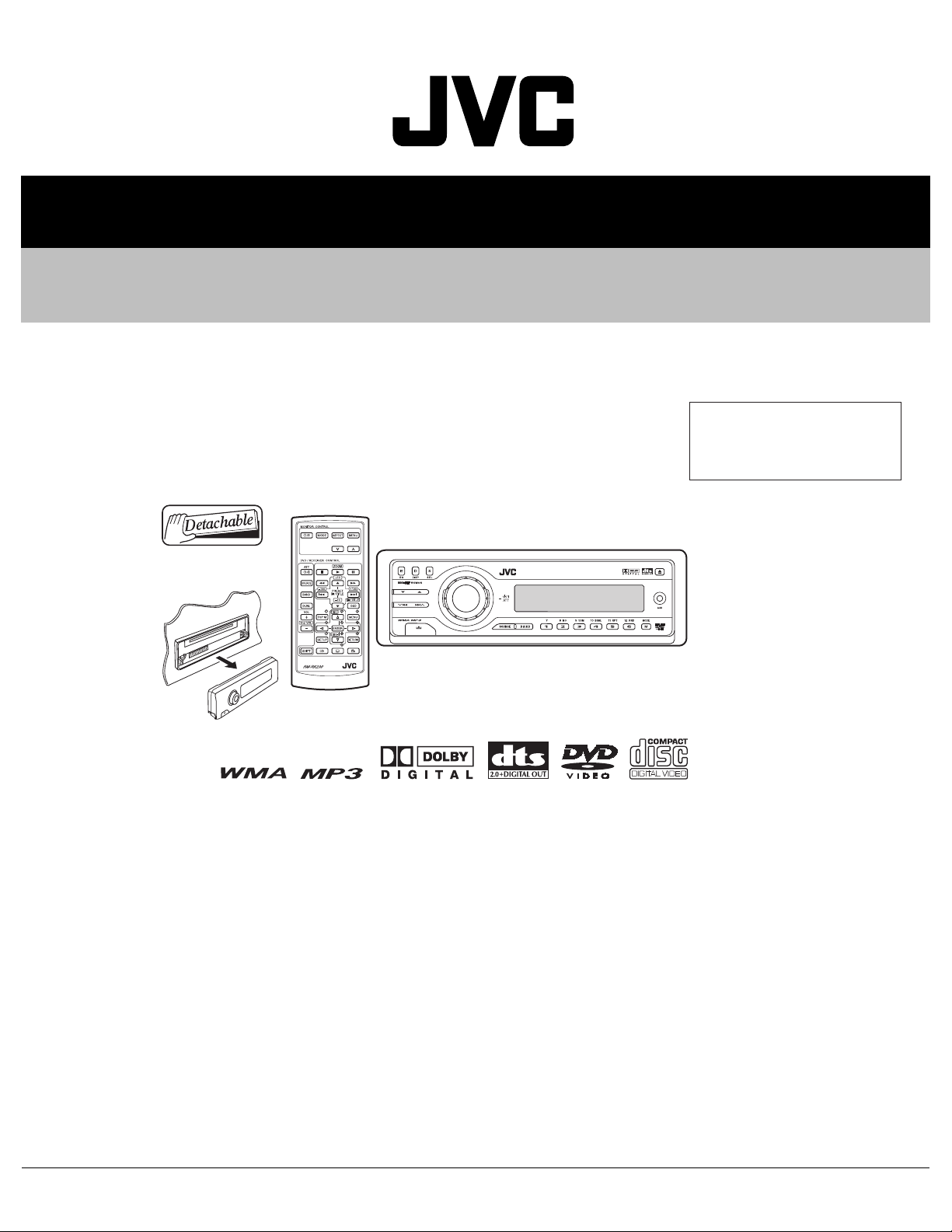
SERVICE MANUAL
DVD/CD RECEIVER
MA17520052
KD-DV6104,KD-DV6103
Area suffix
UI ---------------------------- India
TABLE OF CONTENTS
1 PRECAUTIONS . . . . . . . . . . . . . . . . . . . . . . . . . . . . . . . . . . . . . . . . . . . . . . . . . . . . . . . . . . . . . . . . . . . . . . . 1-3
2 SPECIFIC SERVICE INSTRUCTIONS . . . . . . . . . . . . . . . . . . . . . . . . . . . . . . . . . . . . . . . . . . . . . . . . . . . . . . 1-6
3 DISASSEMBLY . . . . . . . . . . . . . . . . . . . . . . . . . . . . . . . . . . . . . . . . . . . . . . . . . . . . . . . . . . . . . . . . . . . . . . . 1-7
4 ADJUSTMENT . . . . . . . . . . . . . . . . . . . . . . . . . . . . . . . . . . . . . . . . . . . . . . . . . . . . . . . . . . . . . . . . . . . . . . . 1-21
5 TROUBLESHOOTING . . . . . . . . . . . . . . . . . . . . . . . . . . . . . . . . . . . . . . . . . . . . . . . . . . . . . . . . . . . . . . . . . 1-29
COPYRIGHT © 2005 Victor Company of Japan, Limited
No.MA175
2005/2
Page 2
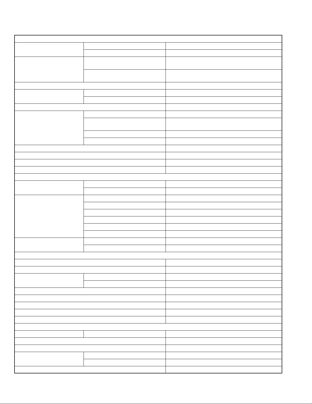
SPECIFICATION
AUDIO AMPLIFIER SECTION
Maximum Power Output Front 50 W per channel
Rear 50 W per channel
Continuous Power Output (RMS) Front 19 W per channel into 4 Ω, 40 Hz to 20 000 Hz at no more
than 0.8% total harmonic distortion.
Rear 19 W per channel into 4 Ω, 40 Hz to 20 000 Hz at no more
than 0.8% total harmonic distortion.
Load Impedance 4 Ω (4 Ω to 8 Ω allowance)
Equalizer Control Range Frequencies 60 Hz, 150 Hz, 400 Hz, 1 kHz, 2.4 kHz, 6 kHz, 15 kHz
Level ±10 dB
Signal-to-Noise Ratio 70 dB
Audio Output Level Analog (2nd AUDIO OUT) 6 mW (at 16 Ω)
Digital (DIGITAL OUT: Optical) Signal wave length : 660 nm
Output level : -21 dBm to -15 dBm
Line-Out Level/Impedance 5.0 V/20 kΩ load (full scale)
Output Impedance 1 kΩ
Subwoofer-Out Level/Impedance 2.0 V/20 kΩ load (full scale)
Color System PAL/NTSC
Video Output (composite) 1 Vp-p/75 Ω
Other Terminals LINE IN, CD changer
TUNER SECTION
Frequency Range FM 87.5 MHz to 108.0 MHz
AM 531 kHz to 1 602 kHz
FM Tuner Usable Sensitivity 11.3 dBf (1.0 µV/75 Ω)
50 dB Quieting Sensitivity 16.3 dBf (1.8 µV/75 Ω)
Alternate Channel Selectivity (400 kHz) 65 dB
Frequency Response 40 Hz to 15 000 Hz
Stereo Separation 35 dB
Capture Ratio 1.5 dB
AM Tuner Sensitivity 20 µV
Selectivity 35 dB
DVD/CD PLAYER SECTION
Signal Detection System Non-contact optical pickup (semiconductor laser)
Number of Channels 2 channels (stereo)
Frequency Response DVD, fs=48 kHz/96 kHz 16 Hz to 22 000 Hz
VCD, CD, MP3, WMA 16 Hz to 20 000 Hz
Dynamic Range 96 dB
Signal-to-Noise Ratio 98 dB
Wow and Flutter Less than measurable limit
MP3 (MPEG Audio Layer 3) Max. Bit Rate: 320 kbps
WMA (Windows Media Audio) Max. Bit Rate: 192 kbps
GENERAL
Power Requirement Operating Voltage DC 14.4 V (11 V to 16 V allowance)
Grounding System Negative ground
Allowable Operating Temperature 0°C to +40°C
Dimensions (W × H × D) Installation Size (approx.) 182 mm × 52 mm × 158 mm
Panel Size (approx.) 188 mm × 58 mm × 11 mm
Mass (approx.) 1.7 kg (excluding accessories)
Design and specifications are subject to change without notice.
1-2 (No.MA175)
Page 3
1.1 Safety Precautions
SECTION 1
PRECAUTIONS
!
!
Burrs formed during molding may be left over on some parts of the chassis. Therefore,
pay attention to such burrs in the case of preforming repair of this system.
Please use enough caution not to see the beam directly or touch it in case of an
adjustment or operation check.
(No.MA175)1-3
Page 4
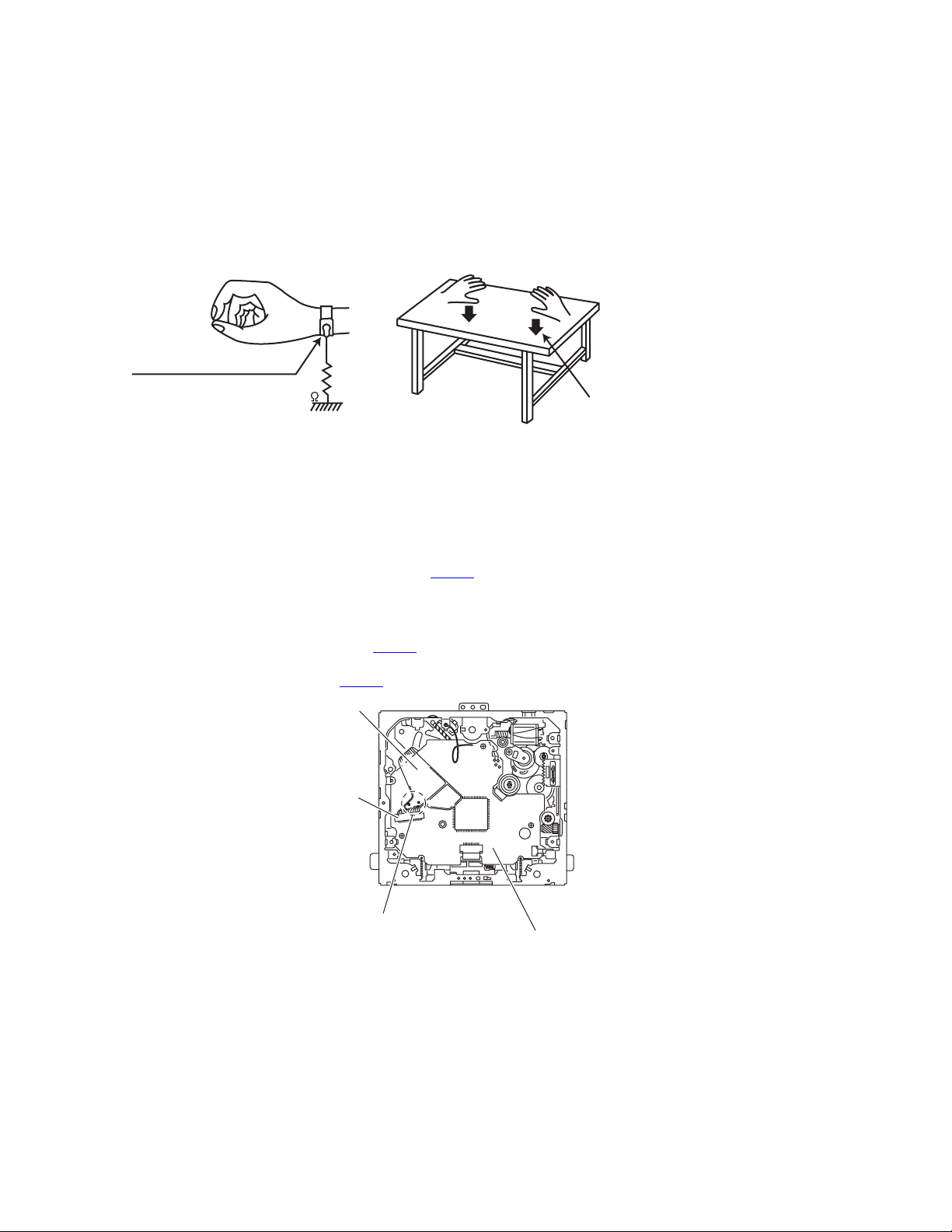
1.2 Preventing static electricity
Electrostatic discharge (ESD), which occurs when static electricity stored in the body, fabric, etc. is discharged, can destroy the laser
diode in the traverse unit (optical pickup). Take care to prevent this when performing repairs.
1.2.1 Grounding to prevent damage by static electricity
Static electricity in the work area can destroy the optical pickup (laser diode) in devices such as CD players.
Be careful to use proper grounding in the area where repairs are being performed.
(1) Ground the workbench
Ground the workbench by laying conductive material (such as a conductive sheet) or an iron plate over it before placing the
traverse unit (optical pickup) on it.
(2) Ground yourself
Use an anti-static wrist strap to release any static electricity built up in your body.
(caption)
Anti-static wrist strap
1M
Conductive material
(conductive sheet) or iron plate
(3) Handling the optical pickup
• In order to maintain quality during transport and before installation, both sides of the laser diode on the replacement optical
pickup are shorted. After replacement, return the shorted parts to their original condition.
(Refer to the text.)
• Do not use a tester to check the condition of the laser diode in the optical pickup. The tester's internal power source can easily
destroy the laser diode.
1.3 Handling the traverse unit (optical pickup)
(1) Before disconnecting the flexible wire from the connector CN101
on the flexible wire.
Caution:
If you do not follow this instruction, the DVD pickup may be damaged.
(2) Disconnect the flexible wire from the connector CN101
(3) Remove the solders from the short-circuit points on the flexible wire after replacing the DVD pickup.
(4) Connect the flexible wire to the connector CN101
Flexible wire
CN101
on the mechanism control board.
on the mechanism control board.
on the mechanism control board, solder the short-circuit points
1-4 (No.MA175)
Short-circuit points
Mechanism control board
Page 5

1.4 Important for laser products
!
1.CLASS 1 LASER PRODUCT
2.DANGER : Invisible laser radiation when open and inter
lock failed or defeated. Avoid direct exposure to beam.
3.CAUTION : There are no serviceable parts inside the
Laser Unit. Do not disassemble the Laser Unit. Replace
the complete Laser Unit if it malfunctions.
4.CAUTION : The CD,MD and DVD player uses invisible
laser radiation and is equipped with safety switches which
prevent emission of radiation when the drawer is open and
the safety interlocks have failed or are defeated. It is
dangerous to defeat the safety switches.
5.CAUTION : If safety switches malfunction, the laser is able
to function.
6.CAUTION : Use of controls, adjustments or performance of
procedures other than those specified here in may result in
hazardous radiation exposure.
Please use enough caution not to
see the beam directly or touch it
in case of an adjustment or operation
check.
REPRODUCTION AND POSITION OF LABELS
WARNING LABEL
CAUTION : Visible and Invisible
CLASS 1
LASER PRODUCT
laser radiation when open and
interlock failed or defeated.
AVOID DIRECT EXPOSURE TO
BEAM. (e)
ADVARSEL : Synlig og usynlig
laserstråling når maskinen er
åben eller interlocken fejeler.
Undgå direkte eksponering til
stråling. (d)
VARNING : Synlig och
osynling laserstrålning när
den öppnas och spärren är
urkopplad. Betrakta ej
strålen. (s)
VARO : Avattaessa ja suojalukitus
ohitettuna tai viallisena olet alttiina
näkyvälle ja näkymättömälle
lasersäteilylle. Vältä säteen
kohdistumista suoraan itseesi. (f)
(No.MA175)1-5
Page 6

SECTION 2
SPECIFIC SERVICE INSTRUCTIONS
This service manual does not describe SPECIFIC SERVICE INSTRUCTIONS.
1-6 (No.MA175)
Page 7
SECTION 3
DISASSEMBLY
3.1 Main body section
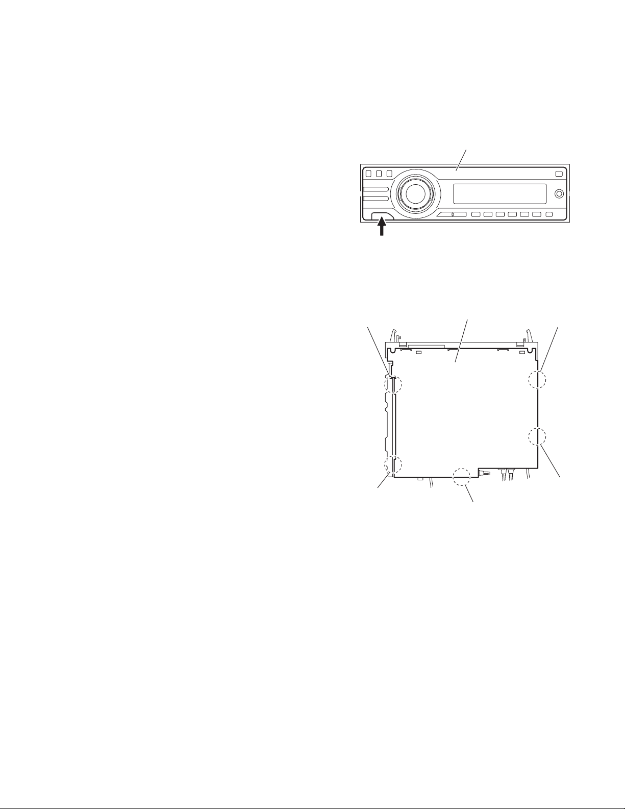
3.1.1 Removing the front panel assembly
(See Fig.1)
Push the detach button in the lower left part of the front panel assembly and remove the front panel assembly.
3.1.2 Removing the bottom cover
(See Fig.2)
Reference:
Remove the front panel assembly as required.
(1) Release the two joints a, two joints b and joint c.
(2) Remove the bottom cover from the main body.
Caution:
Do not damage the main board when releasing the joints using
a screwdriver or a similar tool.
Detach button
b
Front panel assembly
Fig.1
Bottom cover
a
a
b
c
Fig.2
(No.MA175)1-7
Page 8
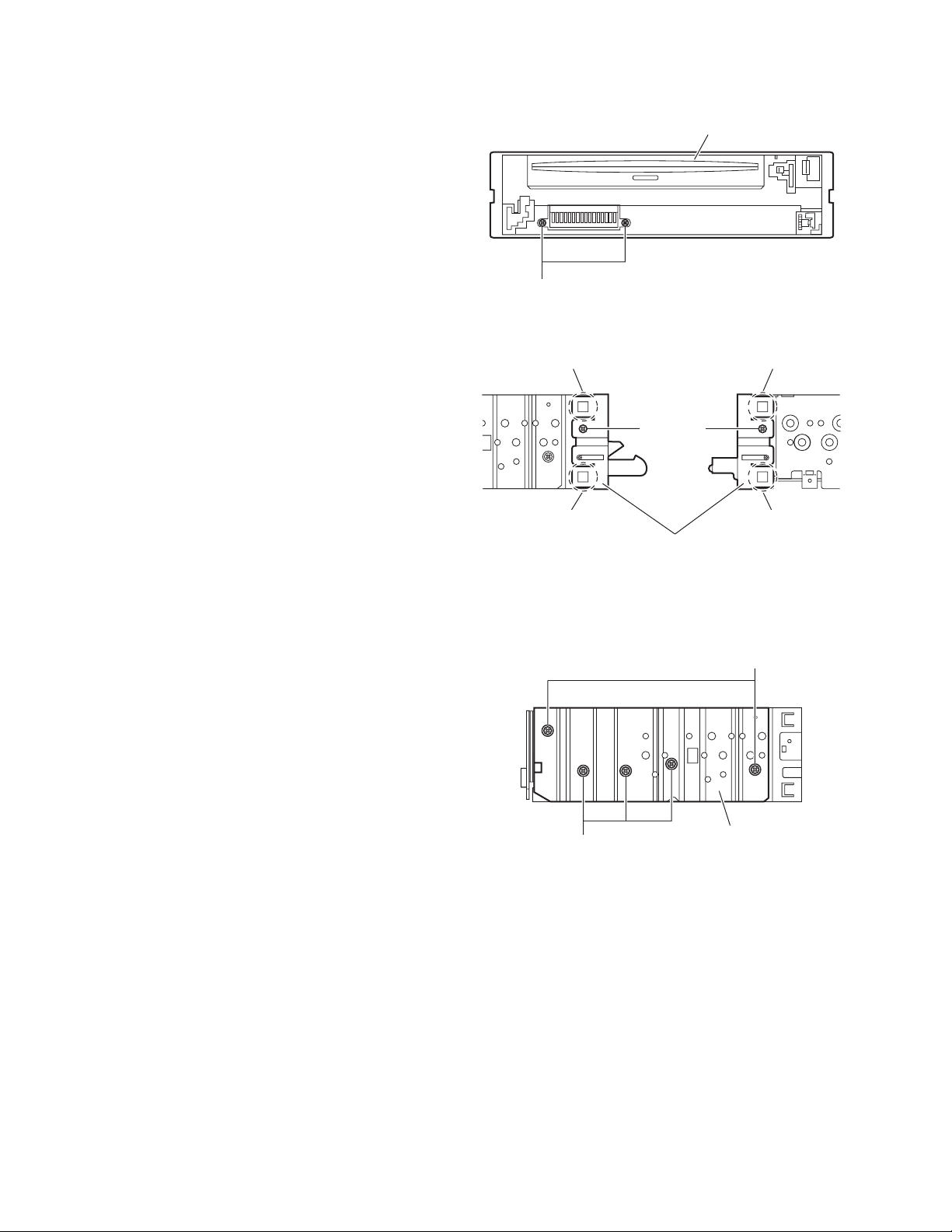
3.1.3 Removing the front chassis assembly
(See Figs.3 and 4)
• Remove the front panel assembly and bottom cover.
(1) From the front side of the main body, remove the two
screws A attaching the front chassis assembly. (See
Fig.3.)
(2) From the both sides of the main body, remove the two
screws B attaching the front chassis assembly. (See
Fig.4.)
(3) Release the two joints d and two joints e. (See Fig.4.)
Front chassis assembly
A
Fig.3
3.1.4 Removing the side heat sink
(See Fig.5)
Reference:
Remove the front panel and front chassis assemblies as re-
quired.
From the left side of the main body, remove the two screws C and
three screws D attaching the side heat sink.
d
B
d
Front chassis assembly
Fig.4
e
B
e
C
1-8 (No.MA175)
D
Side heat sink
Fig.5
Page 9
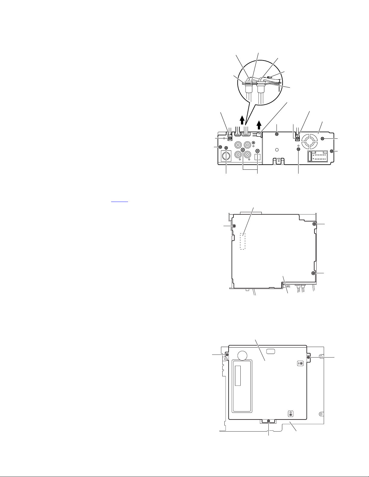
3.1.5 Removing the rear bracket
(See Fig.6)
• Remove the bottom cover.
(1) From the back side of the main body, remove the two
screws E, two screws E', screw F, two screws G and three
screws H attaching the rear bracket.
(2) Remove the LINE IN, SUBWOOFER and AUDIO OUT ca-
bles from the rear bracket in the direction of the arrow.
Reference:
• When attaching the LINE IN and SUBWOOFER cables, insert them in the slots of the rear bracket and hang them on
a wire holder.
• When attaching the screws E', attach the cable holders with
them.
3.1.6 Removing the main board
(See Figs.6 and 7)
• Remove the front panel assembly, bottom cover, front chassis
assembly and side heat sink.
Reference:
Remove the rear bracket as required.
(1) From the back side of the main body, remove the three
screws H attaching the main board. (See Fig.6.)
(2) From the bottom side of the main body, remove the three
screws J attaching the main board. (See Fig.7.)
(3) Disconnect the connector CN961
the DVD mechanism assembly and take out the main
board from the main body. (See Fig.7.)
on the main board from
SUBWOOFER cable
Rear bracket
Cable holder
E'
H
F
CN961
G
Slot
LINE IN cable
Wire holder
AUDIO OUT cable
HEE'
Fig.6
Slot
Cable holder
Rear bracket
E
H
3.1.7 Removing the DVD mechanism assembly
(See Fig.8)
• Remove the front panel assembly, bottom cover, front chassis
assembly, side heat sink and main board.
(1) From the inside of the top chassis, remove the three
screws K attaching the DVD mechanism assembly.
(2) Take out the DVD mechanism assembly from the top chas-
sis.
J
DVD mechanism assembly
K
J
J
Main board
Fig.7
K
K
Fig.8
Top chassis
(No.MA175)1-9
Page 10

3.1.8 Removing the main sub board
(See Figs.9 to 11)
• Remove the front panel assembly, bottom cover, front chassis
assembly, side heat sink, main board and DVD mechanism assembly.
(1) From the top side of the DVD mechanism assembly, re-
move the two screws L attaching the dust cover. (See
Fig.9.)
(2) Remove the dust cover from the DVD mechanism assem-
bly. (See Fig.9.)
Reference:
When attaching the dust cover, align the joints f in the
holes of the dust cover before attaching the screws L.
(See Fig.9.)
(3) Release the lock of the connector CN962
board and disconnect the card wire. (See Fig.10.)
(4) Bend the joint g in the direction of the arrow. (See Fig.10.)
(5) Remove the two screws M attaching the main sub board
and remove the main sub board from the DVD mechanism
assembly. (See Fig.10.)
Reference:
• When attaching the main sub board, align the joints h in the
holes of the main sub board before attaching the screws M.
(See Fig.10.)
• When the resolution of DVD mechanism assembly is done
sequentially, remove the two screws N attaching the support
bracket. (See Fig.11.)
• Remove the card wire from the connector CN401
quired. (See Fig.11.)
on the main sub
as re-
DVD mechanism assembly
Dust cover
Fig.9
DVD mechanism assembly
CN962
h
L
Lock
f
L
f
g
M
N
h
Main sub board
Fig.10
Support bracket
Fig.11
Card wire
CN401
Card wire
1-10 (No.MA175)
Page 11

3.1.9 Removing the switch board
(See Figs. 12 to 14)
• Remove the front panel assembly.
(1) From the back side of the front panel assembly, remove the
five screws P attaching the rear cover. (See Fig.12.)
(2) Release the ten joints i attaching the rear cover to the front
panel assembly. (See Fig.13.)
(3) Take out the switch board while lifting the switch board
from the front panel assembly little by little. (See Fig.14.)
Reference:
Remove the volume knob from the front side of the front panel
assembly at the same time.
Note:
Do not lose the compression springs when removing the
switch board. (See Fig.14.)
Rear cover
P
Front panel assembly
P
P
Fig.12
i
i
Rear cover
Switch board
Compression spring
i
i
Fig.13
Front panel assembly
Compression spring
Fig.14
(No.MA175)1-11
Page 12

3.2 DVD mechanism assembly
3.2.1 Removing the mechanism control board
(See Fig.1)
Caution:
Before disconnecting the flexible wire extending from the DVD
pickup, solder the short-circuit point on the flexible wire using
a grounding soldering iron. If you do not follow this instruction,
the DVD pickup may be damaged.
(1) Turn over the body, and solder the short-circuit points on
the flexible wire extending from the DVD pickup.
(2) Disconnect the flexible wire from connector CN101
mechanism control board.
(3) Disconnect the card wire from connector CN201
mechanism control board.
(4) Disconnect the flexible wire from connector CN202
mechanism control board.
(5) Unsolder two soldered points a on the mechanism control
board and remove the wire extending from the feed motor.
(6) Remove the screw A attaching the lug wire.
(7) Remove the two screws B and screw C attaching the
mechanism control board.
Caution:
• As the flexible wire to be connected to CN101
attach it to the mechanism control board using a double
tape.
• After reassembling, unsolder the short-circuit points.
on the
on the
on the
, make sure to
Flexible wire
Double tape
CN101
B
Short-circuit points
A
Lug wire
B
CN201
Feed motor
a
C
CN202
Mechanism control board
Fig.1
1-12 (No.MA175)
Page 13

3.2.2 Removing the top cover
(See Fig.2)
(1) Remove the two screws D attaching the top cover on the
back of the body.
(2) Remove the top cover upward.
Reference:
When reassembling, set part b of the top cover under the
bending part c of the chassis frame.
3.2.3 Removing the mechanism section
(See Fig.2 to 4)
• Remove the top cover.
(1) From the bottom of the body, remove the screw E attaching
the lug wire. (See Fig.2.)
(2) Remove the two screws F attaching the right and left stop-
pers on the front side. (See Fig.2.)
(3) Remove the two floating springs on the bottom of the body.
(See Fig.3.)
(4) Move the mechanism section upward and remove from the
chassis frame.
The three damper springs come off from the dampers.
(See Fig.4.)
Caution:
• When reassembling, reattach the damper spring to the
damper respectively and insert the three shafts on the bottom of the mechanism to the dampers.
• Before inserting the shaft to the dampers, apply IPA to the
hole of damper.
Floating spring
Fig.3
Mechanism section
Stopper
F
Top cover
Stopper
F
D
D
b
c
E
Lug wire
Damper SP.(F)
(Silver)
Damper (F)
(Black)
Damper SP.(F)
(Silver)
Damper (F)
(Black)
Fig.4
Damper SP.(R)
(Red)
Damper (R)
(Purple)
Chassis frame
Fig.2
(No.MA175)1-13
Page 14

3.2.4 Removing the clamper unit
(See Fig.5 to 7)
• Remove the top cover and the mechanism section.
(1) Remove the clamper2 spring on the bottom of the mecha-
nism section. (See Figs.5.and 6.)
(2) Release the part d of the clamper spring from the bending
part of the chassis base assembly. (See Fig.7.)
(3) Move the clamper unit in the direction of the arrow and turn.
Release the two joints e and f, then remove the clamper
unit upward. (See Fig.6.)
3.2.5 Reattaching the clamper unit
(See Fig.5 to 9)
(1) Attach the clamper spring to the clamper unit. (See Fig.8.)
(2) Move the clamper unit to set the side joints e and f to each
boss of the chassis base assembly. Make sure that part g
is inserted to the notch of the chassis base assembly. (See
Figs.5 and 9.)
(3) Move the part d of the clamper spring to the outside of the
bending part of the chassis base assembly. (See Fig.7.)
(4) Attach the clamper2 spring to the chassis base assembly.
(See Figs.5 and 6.)
Caution:
When reattaching, temporarily hook the end of the clamper
spring as shown in the figure to make the work easy. (See
Fig.8.)
Clamper unit
Clamper2 spring
Chassis base assembly
Fig.6
Clamper spring
Clamper spring
f
Clamper2 spring
Chassis base assembly
g
d
Chassis base assembly
Fig.7
e
Fig.5
1-14 (No.MA175)
Page 15

Clamper unit
Clamper unit
Clamper spring
Fig.8
Fig.9
g
Notch
(No.MA175)1-15
Page 16

3.2.6 Removing the front unit
(See Fig.10 to 12)
• Remove the top cover and the mechanism section.
(1) Disconnect the flexible wire from connector CN202 on the
mechanism control board at the bottom of the body. (See
Fig.10.)
(2) Remove the screw G attaching the front unit on the top of
the body. (See Fig.11.)
(3) Move the front unit toward the front to release joint h, and
release two joints i and j on the right side of the chassis
base assembly. Then remove the front unit upward. (See
Figs.11 and 12.)
(4) Remove the two screws H attaching the switch board. (See
Fig.12.)
Reference:
You can remove the switch board only without removing the
front unit.
Caution:
When reassembling, attach the flexible wire extending from
the switch board using the double tape. (See Figs.10 and 12.)
Mechanism control board
G
Front unit
h
Fig.11
CN202
Double tape
Fig.10
Flexible wire
Double tape
j
i
H
Switch board
Front unit
G
1-16 (No.MA175)
h
Fig.12
Page 17

3.2.7 Removing the loading arm assembly
(See Fig.13 , 14)
• Remove the top cover, the mechanism section and the front
unit.
(1) From the top of the body, move the loading arm assembly
from the front side upward, and release the bosses from
the right and left joints k and m of the chassis base assembly.
(2) Release the boss from notch n of the connect arm on the
right side of the body, and release the boss from notch p of
the slide cam assembly on the left side.
m
Loading arm assembly
Side cam
assembly
p
m
k
Fig.13
Loading arm assembly
k
n
n
Connect arm
Fig.14
(No.MA175)1-17
Page 18

3.2.8 Removing the rod (L)(R)/roller assembly
(See Fig.15 and 16)
• Remove the top cover, the mechanism section, the front unit
and the loading arm assembly.
(1) Release the rod (L) and (R) from the joints q at the bottom
of the loading arm assembly (See Fig.15.)
(2) Remove the roller assembly from the loading arm assem-
bly. (See Fig.16.)
(3) Remove the two collars and washer from the roller assem-
bly. (See Fig.16.)
Caution:
After attaching the loading arm assembly to the roller assembly, attach the rod (L) and (R). Attach the rods to the right and
left collars of the roller. (See Fig.15.)
When reattaching the rod (L) and (R) to the loading arm assembly, engage each joint as shown in Fig.15. As joints q of
the rod (L), let the rod through q before reattaching it.
Collar
Collar
Rod(R) Rod(L)
q
q
q
Collar
Rod(L)
Rod(R)
q
Loading arm assembly
Fig.15
Roller assembly
Loading arm assembly
q
Rod(L)
q
Collar
Washer
Rod(R)
1-18 (No.MA175)
Fig.16
Page 19

3.2.9 Removing the DVD pickup assembly
(See Fig.17 to 19)
• Remove the mechanism control board.
(1) From the bottom of the body, turn the feed gear in the di-
rection of the arrow to move the DVD pickup outwards.
(See Fig.17.)
(2) Remove the screw J attaching the thrust spring. (See
Fig.17.)
(3) Remove the DVD pickup assembly upward on the L.S.gear
side and release from sub shaft at joint r. Move the lead
screw of the DVD pickup assembly in the direction of the
arrow to release from joint s. (See Fig.18.)
Caution:
• When releasing the lead screw at joint s, the L.S.collar
comes off at the end of the lead screw. When reassembling, reattach the L.S.collar to the lead screw and
engage joint s. (See Fig.18.)
• When reattaching the L.S.collar, reattach it to the point
s of the lead screw, and to the rod (M). Make sure that
the L.S.collar is set on the rod (M) spring. (See Fig.18.)
(4) Remove the screw K attaching the rack spring/ rack plate
on the DVD pickup. (See Fig.19.)
(5) Pull out the lead screw. (See Fig.19.)
Caution:
Perform adjustment after replacing the pickup.
DVD Pickup assembly
DVD Pickup assembly
Feed gear
J
Thrust spring
Fig.17
s
L.S.collar
Rod(M)
Lead screw
Sub shaft
L.S.collar
r
L.S.gear
Fig.18
K
Rack spring
Lead screw
Rack plate
DVD Pickup
Fig.19
(No.MA175)1-19
Page 20

3.2.10 Removing the spindle motor
r
(See Fig.20)
• Remove the mechanism control board.
Remove the two screws L attaching the spindle motor on the
bottom of the body.
Caution:
Perform adjustment when reattaching the spindle motor.
3.2.11 Removing the feed motor assembly
(See Fig.21 and 22)
• Remove the mechanism control board.
(1) Remove the feed TRI. spring on the bottom of the body.
(See Fig.21.)
(2) Remove the two screws M attaching the feed motor as-
sembly. (See Fig.21.)
(3) Remove the slit washer from the motor H. assembly and
pull out the worm wheel. (See Fig.22.)
Remove the two screws N attaching the feed motor. (See
Fig.22.)
Spindle motor
Feed TRI. spring
L
Fig.20
M
Feed motor assembly
1-20 (No.MA175)
Fig.21
Slit washer
Worm wheel
Feed moto
N
Motor H. assembly
Fig.22
Page 21

SECTION 4
ADJUSTMENT
4.1 Test instruments required for adjustment
(1) Digital oscilloscope (100MHz)
(2) Jitter meter
(3) Digital tester
(4) Electric voltmeter
(5) Tracking offset meter
(6) Test Disc : VT501 or VT502
(7) Extension studs : STDV001-3P
(8) Extension cable : EXTDV002-30P
4.3 Connection method
Connection procedure
(1) Attach the front chassis assembly to the main board.
(2) Connect the front panel assembly to the main board.
(3) Attach the heat sink and rear bracket to the main board.
(4) Attach the extension studs to the DVD mechanism assembly.
(5) Connect the DVD mechanism assembly and the main board with a extension cable.
4.2 Standard measuring conditions
Power supply voltage DC14.4V(11 to 16V)
Load impedance 4Ω(2 Speakers connection)
Line Output 20KΩ
Caution:
Be sure to attach the heat sink and rear bracket onto the power
amplifier IC and regulator IC respectively, before supply the
power. If voltage is applied without attaching these parts, the
power amplifier IC and regulator IC will be destroyed by heat.
Extension cable
EXTDV002-30P
Heat sink
Rear bracket
Main board
Extension stud
STDV001-3P
Extension studs
STDV001-3P
(No.MA175)1-21
Page 22

After replacing the pickup, set the unit in the service mode to display a jitter value on the LCD. Confirm that the jitter value measured
with a jitter meter is within 12% of the jitter value displayed on the LCD. If it is within 12%, then adjustment is not necessary. Please
note that a jitter value displayed on the LCD is hex data. Refer to the corresponding decimal notation value using the Jitter Conversion
Table and confirm it with the measured value.
Fix the screws "a", "b" and "c" with screw lock paint.
If the measured jitter value is outside the 12% tolerance range, perform the following adjustments.
c
b
a
Jitter value adjustment procedure (Pickup horizontal level adjustment relative to the DVD recording surface)
(For the adjustment tool use a 3 mm wrench and not a screwdriver, this procedure will make the adjustment easier.)
3 mm wrench
(1) Set the unit to the service mode and display a jitter value (hex data) on the LCD.
(2) Turn each of the screws a, b and c, by a half-turn per step, in the direction that reduces the jitter value in order to minimize it.
(Do not turn a screw more than a half turn at a time, but adjust the screws in the cycle of a → b → c → d → a.)
(3) After completing the adjustment, secure the screws with screw lock paint.
1-22 (No.MA175)
Page 23

4.4 Jitter value conversion table
Load the test DVD and set the unit to the service mode. A jitter value converted to the hex value is displayed on the LCD. Refer to the
corresponding decimal notation value shown in the following Jitter Conversion Table.
The adjustment is OK if the jitter value measured with a jitter meter is within 12% of the jitter value displayed on the LCD.
If the measured jitter value is outside the 12% tolerance range, adjust it to minimize the difference between the measured value and
the displayed value.
Indicated
on the LCD
20A7
2072
203D
2008
1FD2
1F9D
1F68
1F33
1EFE
1EC8
1E93
1E5E
1E29
1DF4
1DBE
1D89
1D54
1D1F
1CEA
1CB4
1C7F
1C4A
1C15
1BE0
1BAA
1B75
1B40
1B0B
1AD6
1AA0
1A6B
1A36
1A01
19CC
1996
1961
192C
18F7
JIT OUT
1957.98
1955.32
1952.66
1950
1947.34
1944.68
1942.02
1939.36
1936.7
1934.04
1931.38
1928.72
1926.06
1923.4
1920.74
1918.08
1915.42
1912.76
1910.1
1907.44
1904.78
1902.12
1899.46
1896.8
1894.14
1891.48
1888.82
1886.16
1883.5
1880.84
1878.18
1875.52
1872.86
1870.2
1867.54
1864.88
1862.22
1859.56
Jitter value
(%)
4.7
3818
4.8
3825
4.9
3832
5.0
3840
5.1
384D
5.2
385A
5.3
3867
5.4
3875
5.5
3882
5.6
388F
5.7
389D
5.8
38AA
5.9
38B7
6.0
38C5
6.1
38D2
6.2
38DF
6.3
38EC
6.4
38FA
6.5
3907
6.6
3914
6.7
3922
6.8
392F
6.9
393C
7.0
394A
7.1
3957
3964
7.2
3971
7.3
397F
7.4
398C
7.5
3999
7.6
39A7
7.7
39B4
7.8
39C1
7.9
39CF
8.0
39DC
8.1
39E9
8.2
39F6
8.3
3A04
8.4
Indicated
on the LCD
18C2
188C
1857
1822
17ED
17B8
1782
174D
1718
16E3
16AE
1678
1643
160E
15D9
15A4
156E
1539
1504
14CF
149A
1464
142F
13FA
13C5
1390
135A
1325
12F0
12BB
1286
1250
121B
11E6
11B1
117C
1146
1111
JIT OUT
1856.9
1854.24
1851.58
1848.92
1846.26
1843.6
1840.94
1838.28
1835.62
1832.96
1830.3
1827.64
1824.98
1822.32
1819.66
1817
1814.34
1811.68
1809.02
1806.36
1803.7
1801.04
1798.38
1795.72
1793.06
1790.4
1787.74
1785.08
1782.42
1779.76
1777.1
1774.44
1771.78
1769.12
1766.46
1763.8
1761.14
1758.48
Jitter value
(%)
3A11
8.5
3A1E
8.6
3A2C
8.7
3A39
8.8
3A46
8.9
3A54
9.0
3A61
9.1
3A6E
9.2
3A7B
9.3
3A89
9.4
3A96
9.5
3AA3
9.6
3AB1
9.7
3ABE
9.8
3ACB
9.9
3AD9
10.0
3AE6
10.1
3AF3
10.2
3B00
10.3
3B0E
10.4
3B1B
10.5
3B28
10.6
3B36
10.7
3B43
10.8
3B50
10.9
3B5E
11.0
3B6B
11.1
3B78
11.2
3B85
11.3
3B93
11.4
3BA0
11.5
3BAD
11.6
3BBB
11.7
3BC8
11.8
3BD5
11.9
3BE3
12.0
3BF0
12.1
3BFD
12.2
Indicated
on the LCD
10DC
10A7
1072
103C
1007
FD2
F9D
F68
F32
EFD
EC8
E93
E5E
E28
DF3
DBE
D89
D54
D1E
CE9
CB4
C7F
C4A
C14
BDF
BAA
B75
B40
B0A
AD5
AA0
A6B
A36
A00
9CB
996
961
92C
JIT OUT
1755.82
1753.16
1750.5
1747.84
1745.18
1742.52
1739.86
1737.2
1734.54
1731.88
1729.22
1726.56
1723.9
1721.24
1718.58
1715.92
1713.26
1710.6
1707.94
1705.28
1702.62
1699.96
1697.3
1694.64
1691.98
1689.32
1686.66
1684
1681.34
1678.68
1676.02
1673.36
1670.7
1668.04
1665.38
1662.72
1660.06
1657.4
Jitter value
(%)
12.3
3C0A
12.4
3C18
12.5
3C25
12.6
3C32
12.7
3C40
12.8
3C4D
12.9
3C5A
13.0
3C68
13.1
3C75
13.2
3C82
13.3
3C8F
13.4
3C9D
13.5
3CAA
13.6
3CB7
13.7
3CC5
13.8
3CD2
13.9
3CDF
14.0
3CED
14.1
3CFA
14.2
3D07
14.3
3D14
14.4
3D22
14.5
3D2F
14.6
3D3C
14.7
3D4A
14.8
3D57
3D64
14.9
3D72
15.0
3D7F
15.1
3D8C
15.2
3D99
15.3
3DA7
15.4
3DB4
15.5
3DC1
15.6
3DCF
15.7
3DDC
15.8
3DE9
15.9
3DF7
16.0
(No.MA175)1-23
Page 24

4.5 Service mode
4.5.1 Standard input/output conditions
Power supply voltage DC14.4V(11 to 16V)
Load impedance 4Ω(2 Speakers connection)
Line Output 20KΩ
4.5.2 Service mode setting procedure
(The DVD does not need to be loaded before starting the following procedure.)
[SEL] button
[STANDBY/ON ATTENUATOR] button
[DISC UP] button
[DISC DOWN] button
(1) Press a [STANDBY/ON ATTENUATOR] button on a main unit and switch it on.
(2) Keep this state more than 2 seconds while continuing pressing the [SEL] button, [STANDBY/ON ATTENUATOR] button and
[SOURCE] button sequentially.
(3) This unit is set by a service mode.
*Exchanging it operate a menu of a service mode with the [DISC UP] button and [DISC DOWN] button.
Operate choice of a menu with a [SEL] button.
[SOURCE] button
1-24 (No.MA175)
Page 25

4.5.3 Operation procedures
Keep this state more than 2 seconds while
continuing pressing the [SEL] button,
[STANDBY/ON ATTENUATOR] button and
[SOURCE] button sequentially.
The unit enters the service mode.
"INIT ALL" is
indicated on the LCD.
"VERSION" is
indicated on the LCD.
"AREA/RGN" is
indicated on the LCD.
"VIDEO" is
indicated on the LCD.
Press the [SEL] key
Press the [SEL] key
Press the [SEL] key
Press the [SEL] key
Initialize all data to the factory setting
: The system control EEPROM is initialized entirely.
Microcomputer version display
************
************
Exchanging it operate each indication with the
[DISC UP] button and [DISC DOWN] button.
Destination area/region display
************
************
************
Exchanging it operate each indication with the
[DISC UP] button and [DISC DOWN] button.
Setting of NTSC or PAL
"NTSC" or "PAL" are indicated on the LCD.
Exchanging it operate each indication with the
[DISC UP] button and [DISC DOWN] button.
System control microcomputer version
DVD version
System control destination
DVD unit destination
DVD unit region
Note:
There is the model that is not equipped with
this mode by a version.
"CLR ERR" is
indicated on the LCD.
A B
Press the [SEL] key
Clear loading/ejection error history
: The error history stored in the EEPROM is cleared.
(No.MA175)1-25
Page 26

A B
"CD ERROR" is
indicated on the LCD.
Frror code (1 byte)
First byte [01] Eject error
Detailed error codes (2 bytes) Displayed with loading/ejection errors only.
First byte
Second byte
(Example) When a switch status error occurs during loading route 3 and
the switch status is L/L/H/H/H (00111B = 07H), the error code
and detailed error code become: [09 3207].
Press the [SEL] key
[09] Loading error
Higher 4 bits
Lower 4 bits
[1] Time out
[2] Switch status error
[3] Swinging error
bit7
bit6,5
bit4
bit3
bit2
bit1
bit0
Route No. (EJECT route No.)
-
1(2)
1(2)
Read loading and ejection error history
: The error history saved in the system control
is read and displayed.
TOT-xxxx : Total error count.
Total error count
(A figure between 0 and 9999 is
displayed. 10000 or more is also
displayed as 9999.)
Enyyzzzz : Latest three error codes.
Detailed error code
Error code
Counter
0nyyzzzz : First five error codes
Detailed error code
Error code
Counter
Exchanging it operate each indication with the
[DISC UP] button and [DISC DOWN] button.
Route No. (Process of error occurrence)
Refer to charts 1.1 and 1.2.
Error type
Disc type (0: 12 cm. 1: 8 cm)
Fixed at 0
SW1 status
SW2 status
SW3 status
SW4 status
REST SW status
SW1/2/3/4
1,1,1,1
0,1,1,1
0,0,1,1
[Rest SW]
[0]
[0]
[0]
Loading
No Disc
Disc insert
detection
Eject
No Disc
Eject
completion
Reload
Disc push in
C D
1-26 (No.MA175)
2(2)
2(2)
2(2)
2(2)
3(1)
3(1)
0,0,0,1
0,0,1,1
0,1,1,1
1,1,1,1
1,1,1,0
1,1,1,0
[0]
[0]
[0]
[0]
[0]
[1]
Load completion
Chart 1.1 12cm Disc switch status transition
Route No. (EJECT route No.)
-
1(2)
1(2)
2(2)
2(2)
3(1)
3(1)
Transition in the center loading (Similar to 12cm in the side loading)
SW1/2/3/4
1,1,1,1
0,1,1,1
0,0,1,1
0,1,1,1
1,1,1,1
1,1,1,0
1,1,1,0
[Rest SW]
[0]
[0]
[0]
[0]
[0]
[0]
[1]
Loading
No Disc
Disc insert
detection
Load completion
Chart 1.2 8cm Disc switch status transition
Eject start
Eject
No Disc
Eject
completion
Eject start
Reload start
Load completion
Reload
Disc push in
Reload start
Load completion
Page 27

C D
"SYS-TEMP" is
indicated on the LCD.
"CHK MODE" is
indicated on the LCD.
"RUNNING" is
indicated on the LCD.
"MEMCHECK" is
indicated on the LCD.
"INIT" is
indicated on the LCD.
Press the [SEL] key
Press the [SEL] key
Press the [SEL] key
Press the [SEL] key
Press the [SEL] key
Thermistor's temperature data readout
: Data in the temperature sensor in the system control
is read every 5 seconds and displayed in hex numbers.
DVD unit check mode
(See section "5.1.4 DVD unit check mode" for details.)
Running mode: For use in running tests.
Memory check
: The remaining data capacity of the disc is displayed on the LCD.
Initialize user set data
: The system control EEPROM is initialized except for the
loading/ejection error history.
(No.MA175)1-27
Page 28

4.5.4 DVD unit check mode
Change LCD indication with a [FF ] button and a [REW ] button.
Check item list
No. A/D key
[1]
1
[2]
2
[3]
3
[4]
4
[5]
5
[6]
6
[DISP]
7
[SOURCE]
8
[SEL]
9
[MODE]
10
[BAND]
11
[DISC UP ]
12
[DISC DW ]
13
[EJECT]
14
Start at normal speed
(After start, it is measured JITTER on the
internal position)
Tracking off on the outermost position of CD
Tracking off on the innermost position of CD
CD_LD lights and laser current is displayed
DVD_LD lights and laser current is displayed
DVD x1 jitter measuring mode
(for use in mechanism measurement)
Indication of EEPROM contents
Initialization of EEPROM contents
Indication of temperature
Search & jitter measurement to an appointed
position of DVD
Setting of MONITOR terminal
DVDx1 double speed start
(After start, it is measured JITTER on the
internal position)
Disc stopped & LD-OFF
OPEN
DVD unit operation
Example of
LCD indication
NORMPLAY
CUR
JIT
EF-BAL
OUTRKOFF
EF-BAL
INTRKOFF
CDLD ON
CUR
JIT
DVDLD ON
CUR
JIT
DVD JITR
CUR
JIT
ROM DATA
ADDR
DATA
ROMCLEAR
JD4-TEMP
TEM
DVD-DL
PLC
JIT
MONITOR
M1
M2
PLAY
CUR
JIT
STOP
DSC OPEN
Indication contents
Laser current value
Jitter value
For EF phase error
For EF phase error
Laser current value
Jitter value
Laser current value
Jitter value
Laser current value
Jitter value
EEPROM address
EEPROM contents
Temperature
(Position measured with VT-501)
Jitter value
Laser current value
Jitter value
Note
1-28 (No.MA175)
Press key [1] of No.1 before an item in which the No.2 or 3 key is pressed.
Press key [1] of No.1 or key [12] of No.12 before an item in which the No. 10 key is pressed and confirm
the indication of jitter value on the LCD.
No.6 starts only a DVD1 layer disk. Even other disks start DVD1 layer.
When No.1 and No.12 are pushed after jitter indication, a focus jump is executed. (only DVD2 layer)
Stop a disk before OPEN, CLOSE by all means. (OPEN and CLOSE are not executed in a disk turn.)
The check mode can be exited either by pressing the [POWER] key or by resetting the unit.
Page 29

5.1 16 PIN CORD DIAGRAM
8
GN
GN/BK
7
6
5
4
3
2
1
VI/BK
VI
BL
BL/WH
RD
BK
WH/BK
GY/BK
OR/WH
WH
GY
BR
YG
YL
10
11
12
13
14
15
16
SECTION 5
TROUBLESHOOTING
9
BK
RD
BL
WH
BR
YG
Black
Red
Blue
White
Brown
Yellow Green
GN
VI
GY
YL
OR
Green
Violet
Gray
Yellow
Orange
1 BK
16 YL
2 RD
15 OR/WH
9 WH
10 WH/BK
12 GY
11 GY/BK
8 GN
7 GN/BK
5 VI
6 VI/BK
3 BL/WH
13 BR
4 BL
GND
MEMORY
ACC
ILL
FL+
FL-
FR+
FR-
RL+
RL-
RR+
RR-
REMOTE
TEL
ANT
REMOTE OUT
TEL MUTING
ILLUMINATION
CONTROL
GND
14 YG
RR
FR
FL
RL
REMOTE
ILL
PARKING
Rear Right
Front Right
Front Left
Rear Left
Remote
Illuminations Control
POWER ANTENNA
ANT
ACC
TEL
GND
MEMORY
PARKING
Auto Antenna
ACC Line
Telephone Muting
Ground
Memory Backup Battery+
Parking Brake
PARKING
BRAKE
(No.MA175)1-29
Page 30

Victor Company of Japan, Limited
AV & MULTIMEDIA COMPANY CAR ELECTRONICS CATEGORY 10-1,1chome,Ohwatari-machi,Maebashi-city,371-8543,Japan
(No.MA175)
Printed in Japan
VPT
 Loading...