

Page 1
MA111200411
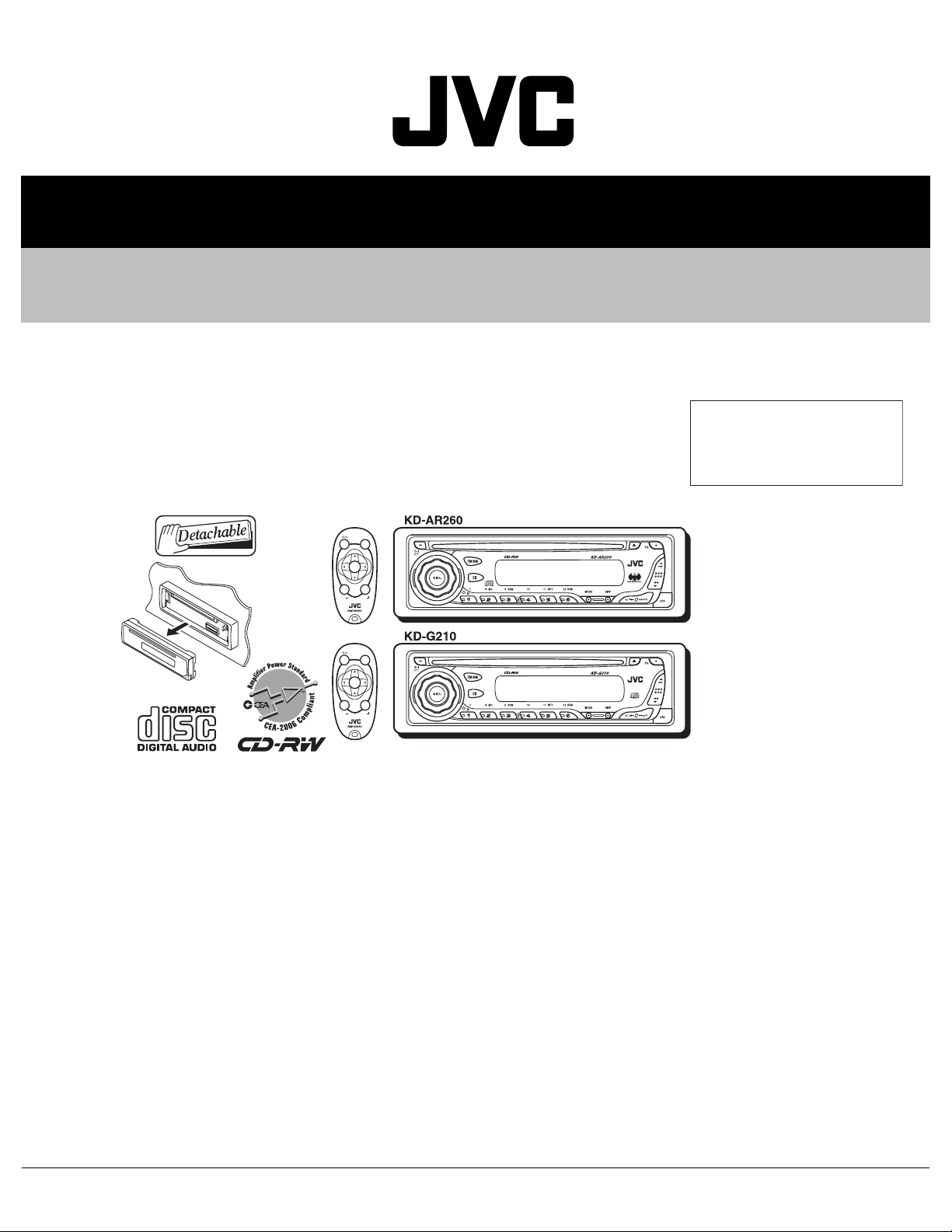
SERVICE MANUAL
CD RECEIVER
KD-AR260,KD-G210
J ------------- Northern America
SOUND
ATT
U
SOURCE
F
R
D
VOL
VOL
SOUND
ATT
U
SOURCE
F
R
D
VOL
VOL
Area suffix
TABLE OF CONTENTS
1 PRECAUTIONS . . . . . . . . . . . . . . . . . . . . . . . . . . . . . . . . . . . . . . . . . . . . . . . . . . . . . . . . . . . . . . . . . . . . . . . 1-3
2 SPECIFIC SERVICE INSTRUCTIONS . . . . . . . . . . . . . . . . . . . . . . . . . . . . . . . . . . . . . . . . . . . . . . . . . . . . . . 1-5
3 DISASSEMBLY . . . . . . . . . . . . . . . . . . . . . . . . . . . . . . . . . . . . . . . . . . . . . . . . . . . . . . . . . . . . . . . . . . . . . . . 1-6
4 ADJUSTMENT . . . . . . . . . . . . . . . . . . . . . . . . . . . . . . . . . . . . . . . . . . . . . . . . . . . . . . . . . . . . . . . . . . . . . . . 1-24
5 TROUBLESHOOTING . . . . . . . . . . . . . . . . . . . . . . . . . . . . . . . . . . . . . . . . . . . . . . . . . . . . . . . . . . . . . . . . . 1-25
COPYRIGHT © 2004 Victor Company of Japan, Limited
No.MA111
2004/11
Page 2

SPECIFICATION
AUDIO AMPLIFIER SECTION
Power Output 18 W RMS × 4 Channels at 4 Ω and [< or =] 1 % THD + N
Signal to Noise Ratio 80 dBA (reference: 1 W into 4 Ω)
Load Impedance 4 Ω (4 Ω to 8 Ω allowance)
Tone Control Range Bass ±10 dB at 100 Hz
Treble ±10 dB at 10 kHz
Frequency Response 40 Hz to 20 000 Hz
Line-Out Level/Impedance 2.5 V/20 kΩ load (full scale)
Output Impedance 1 kΩ
TUNER SECTION
Frequency Range FM 87.5 MHz to 107.9 MHz
AM 530 kHz to 1 710 kHz
FM Tuner Usable Sensitivity 11.3 dBf (1.0 µV/75 Ω)
50 dB Quieting Sensitivity 16.3 dBf (1.8 µV/75 Ω)
Alternate Channel Selectivity (400 kHz) 65 dB
Frequency Response 40 Hz to 15 000 Hz
Stereo Separation 35 dB
Capture Ratio 1.5 dB
AM Tuner Sensitivity 20 µV
Selectivity 35 dB
CD PLAYER SECTION
Type Compact disc player
Signal Detection System Non-contact optical pickup (semiconductor laser)
Number of channels 2 channels (stereo)
Frequency Response 5 Hz to 20 000 Hz
Dynamic Range 96 dB
Signal-to-Noise Ratio 98 dB
Wow and Flutter Less than measurable limit
GENERAL
Power Requirement Operating Voltage DC 14.4 V (11 V to 16 V allowance)
Grounding System Negative ground
Allowable Operating Temperature 0ºC to +40ºC (32ºF to 104ºF)
Dimensions (W × H × D) Installation Size (approx.) 182 mm × 52 mm × 150 mm (7-3/16" × 2-1/16" × 5-15/16")
Panel Size (approx.) 188 mm × 58 mm × 11 mm (7-7/16" × 2-5/16" × 7/16")
Mass (approx.) 1.3 kg (2.9 lbs) (excluding accessories)
Design and specifications are subject to change without notice.
1-2 (No.MA111)
Page 3
1.1 Safety Precautions
SECTION 1
PRECAUTIONS
!
!
Burrs formed during molding may be left over on some parts of the chassis. Therefore,
pay attention to such burrs in the case of preforming repair of this system.
Please use enough caution not to see the beam directly or touch it in case of an
adjustment or operation check.
(No.MA111)1-3
Page 4
1.2 Preventing static electricity
Electrostatic discharge (ESD), which occurs when static electricity stored in the body, fabric, etc. is discharged, can destroy the laser
diode in the traverse unit (optical pickup). Take care to prevent this when performing repairs.
1.2.1 Grounding to prevent damage by static electricity
Static electricity in the work area can destroy the optical pickup (laser diode) in devices such as CD players.
Be careful to use proper grounding in the area where repairs are being performed.
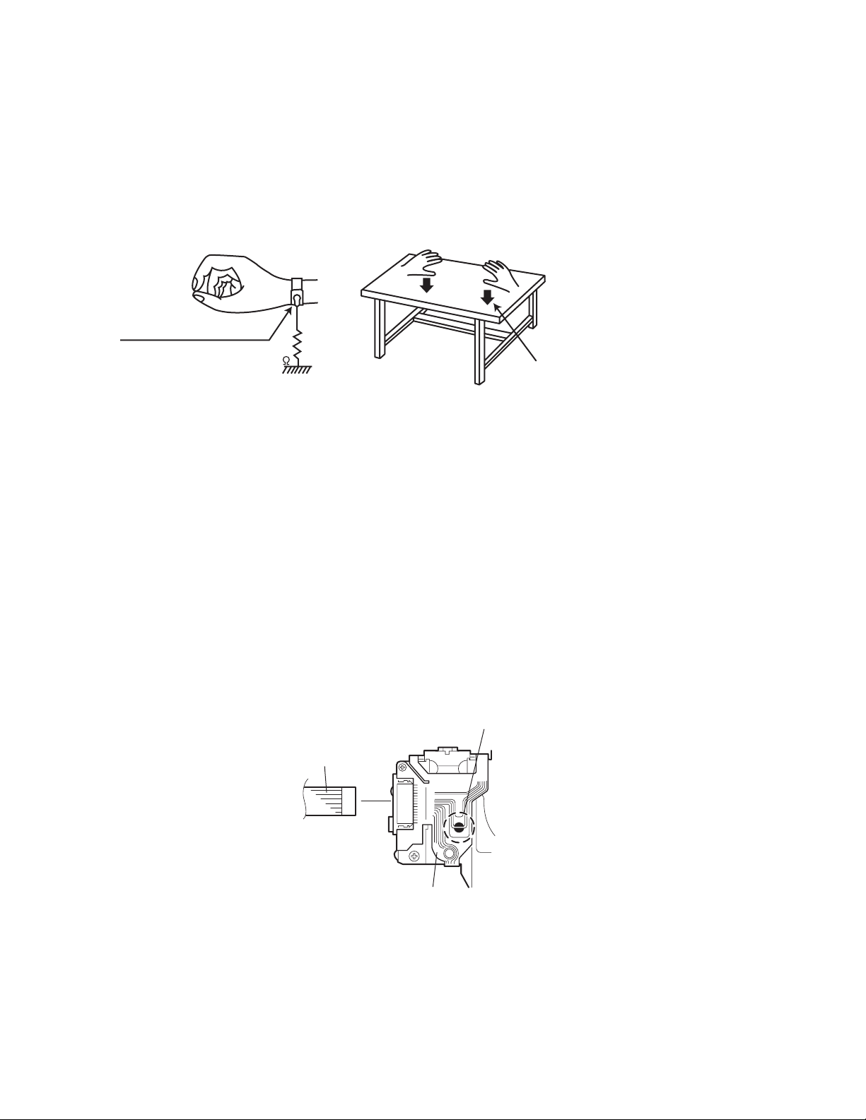
(1) Ground the workbench
Ground the workbench by laying conductive material (such as a conductive sheet) or an iron plate over it before placing the
traverse unit (optical pickup) on it.
(2) Ground yourself
Use an anti-static wrist strap to release any static electricity built up in your body.
(caption)
Anti-static wrist strap
1M
Conductive material
(conductive sheet) or iron plate
(3) Handling the optical pickup
• In order to maintain quality during transport and before installation, both sides of the laser diode on the replacement optical
pickup are shorted. After replacement, return the shorted parts to their original condition.
(Refer to the text.)
• Do not use a tester to check the condition of the laser diode in the optical pickup. The tester's internal power source can easily
destroy the laser diode.
1.3 Handling the traverse unit (optical pickup)
(1) Do not subject the traverse unit (optical pickup) to strong shocks, as it is a sensitive, complex unit.
(2) Cut off the shorted part of the flexible cable using nippers, etc. after replacing the optical pickup. For specific details, refer to the
replacement procedure in the text. Remove the anti-static pin when replacing the traverse unit. Be careful not to take too long a
time when attaching it to the connector.
(3) Handle the flexible cable carefully as it may break when subjected to strong force.
(4) It is not possible to adjust the semi-fixed resistor that adjusts the laser power. Do not turn it.
1.4 Attention when traverse unit is decomposed
*Please refer to "Disassembly method" in the text for the CD pickup unit.
• Apply solder to the short land before the flexible wire is disconnected from the connector on the CD pickup unit.
(If the flexible wire is disconnected without applying solder, the CD pickup may be destroyed by static electricity.)
• In the assembly, be sure to remove solder from the short land after connecting the flexible wire.
Short-circuit point
(Soldering)
Flexible wire
1-4 (No.MA111)
Pickup
Page 5

SECTION 2
SPECIFIC SERVICE INSTRUCTIONS
This service manual does not describe SPECIFIC SERVICE INSTRUCTIONS.
(No.MA111)1-5
Page 6
SECTION 3
DISASSEMBLY
3.1 Main body
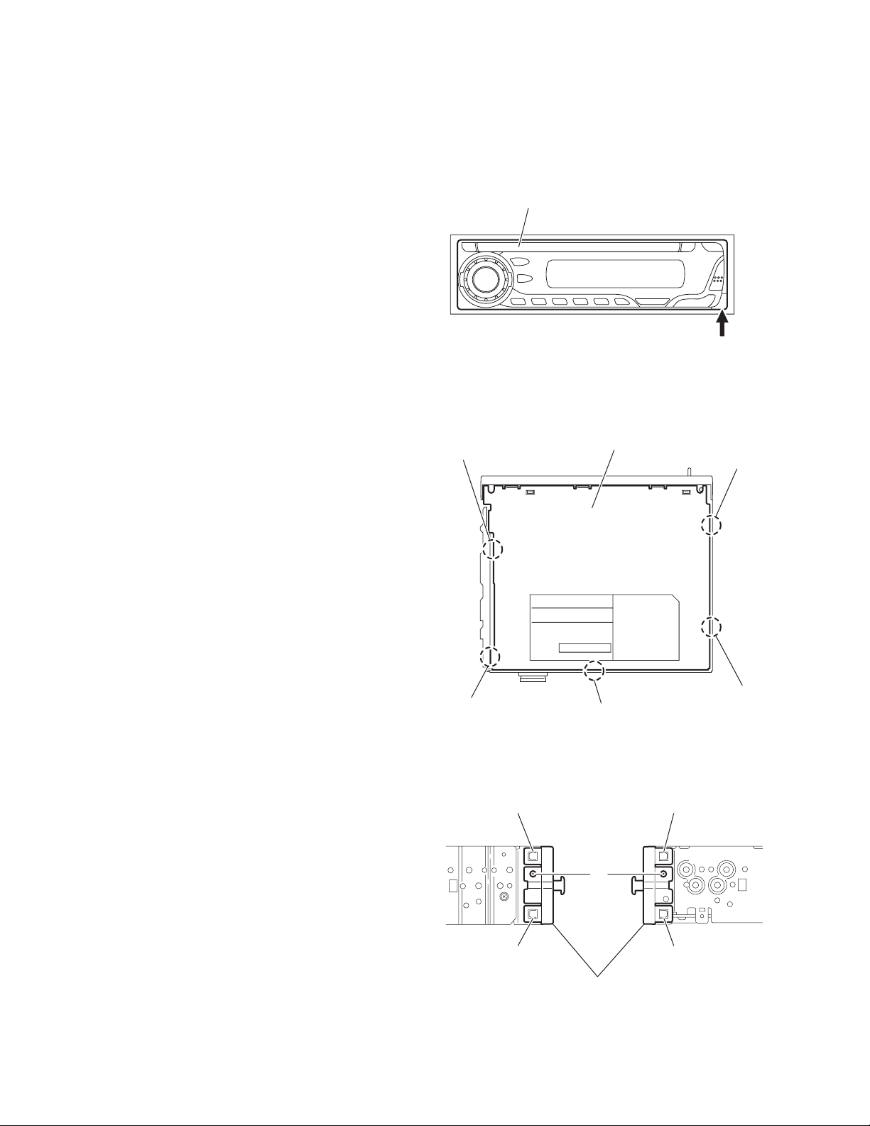
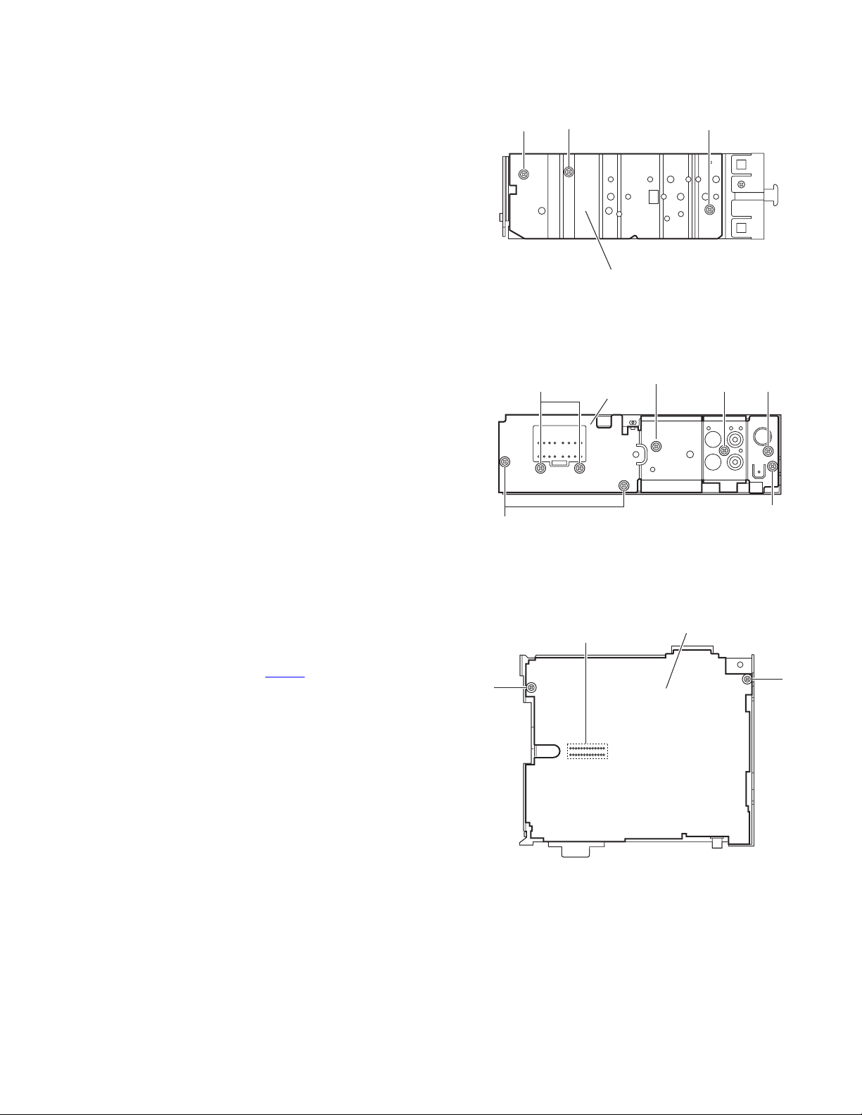
3.1.1 Removing the front panel assembly
(See Fig.1)
(1) Push the detach button in the lower right part of the front
panel assembly and remove the front panel assembly.
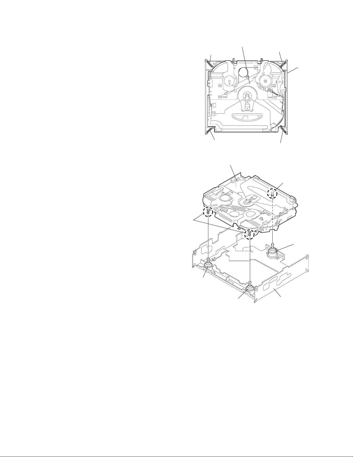
3.1.2 Removing the bottom cover
(See Fig.2)
(1) Turn the main body up side down.
(2) Insert a screwdriver under the joints to release the two
joints a on the left side, two joints b on the right side and
joint c on the back side of the main body, then remove the
bottom cover from the main body.
CAUTION:
When releasing the joints using a screwdriver, do not damage
the main board.
Front panel assembly
Joint a
Detach button
Fig.1
Bottom cover
Joint b
3.1.3 Removing the front chassis assembly
(See Fig.3)
• Prior to performing the following procedures, remove the front
panel assembly and bottom cover.
(1) Remove the screw A on the both sides of the main body.
(2) Release the two joints d and two joints e on the both sides
of the main body, then remove the front chassis assembly
toward the front.
1-6 (No.MA111)
Joint a
Joint c
Fig.2
Joint d Joint e
A
Joint d
Front chassis assembly
Fig.3
Joint e
Joint b
Page 7
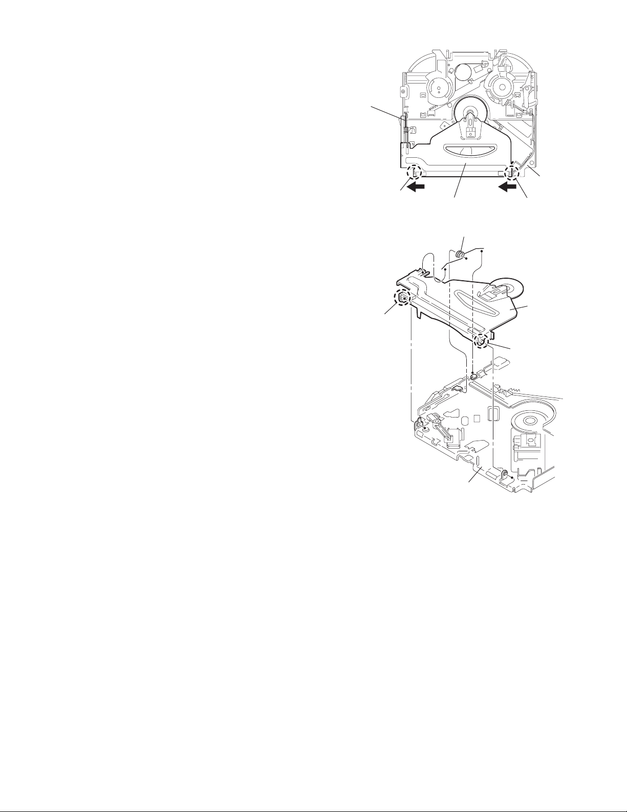
3.1.4 Removing the side panel
(See Fig.4)
• Prior to performing the following procedure, remove the front
panel assembly as required.
(1) Remove the screw B and two screws C attaching the side
panel on the left side of the main body, and remove the side
panel.
3.1.5 Removing the rear bracket
(See Fig.5)
• Prior to performing the following procedure, remove the bottom
cover.
(1) Remove the three screws D, three screws E and two
screws F attaching the rear bracket on the back side of the
main body.
(2) Remove the rear bracket.
BCC
Side panel
Fig.4
EF
Rear bracket
F
E
3.1.6 Removing the main board
(See Fig.6)
• Prior to performing the following procedure, remove the front
panel assembly, front chassis assembly, side panel, bottom
cover and rear bracket.
(1) Remove the two screws G attaching the main board.
(2) Disconnect the connector CN501
board.
and remove the main
G
D
D
Fig.5
Main board
CN501
G
Fig.6
(No.MA111)1-7
Page 8
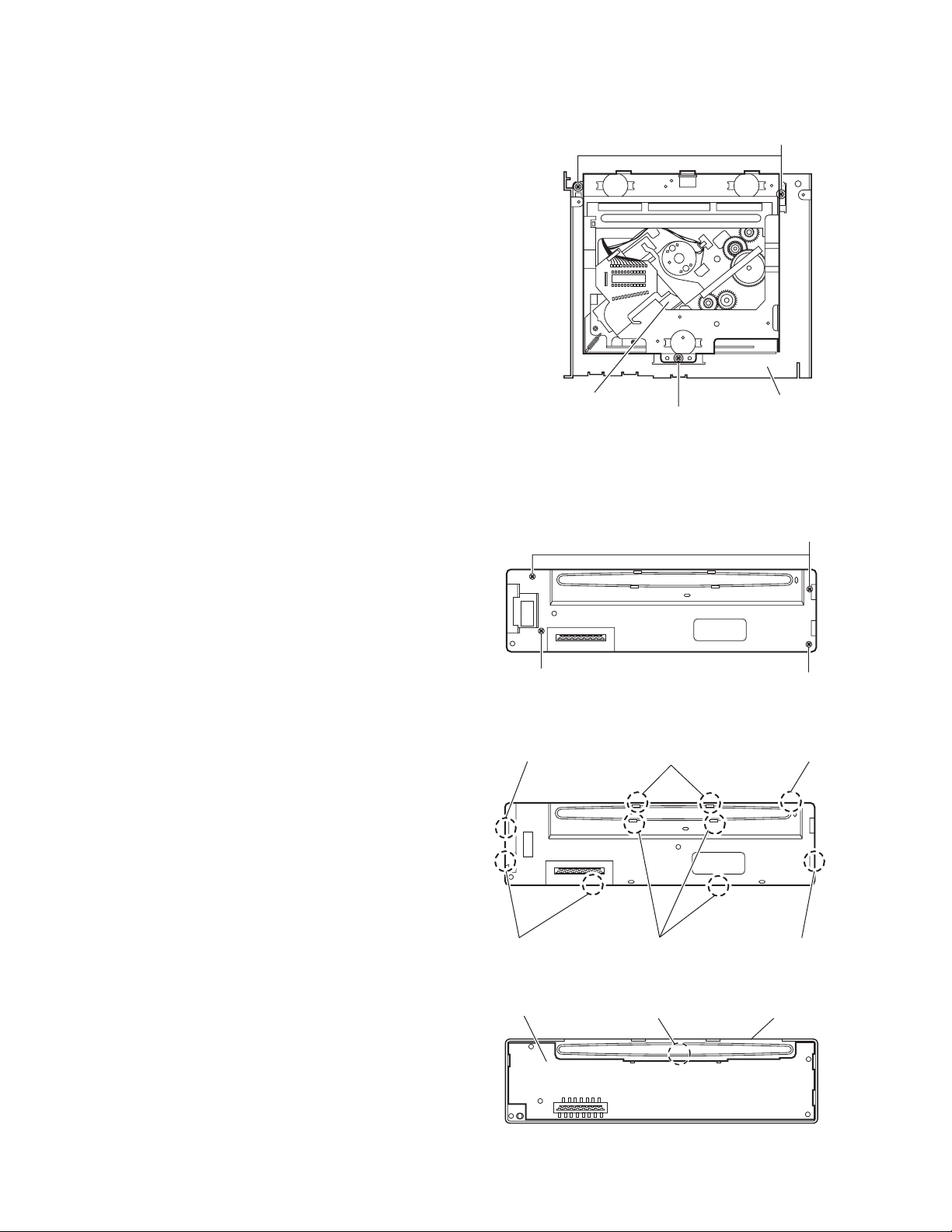
3.1.7 Removing the CD mechanism assembly
f
(See Fig. 7)
• Prior to performing the following procedure, remove the front
panel assembly, front chassis assembly, side panel, bottom
cover, rear bracket, main board and CD mechanism board.
(1) Remove the three screws H attaching the top chassis.
(2) Take out the CD mechanism assembly.
H
3.1.8 Removing the front board
(See Figs.8 to 10)
• Prior to performing the following procedure, remove the front
panel assembly.
(1) Remove the four screws J on the back side of the front pan-
el assembly. (See Fig.8.)
(2) Release the ten joints f. (See Fig.9.)
(3) Release the joint g and take out the front board. (See
Fig.10.)
CD mechanism assembly
Fig.7
J
Fig.8
Joint f Joints f
Top chassis
H
J
J
Joints
1-8 (No.MA111)
Joints f
Front board
Joints f
Fig.9
Joint g
Fig.10
Joint f
Front panel assembly
Page 9

3.2 CD Mechanism Assembly
A
3.2.1 Removing the top cover
(See Figs.1 and 2)
(1) Remove the two screws A on the both side of the body.
(2) Lift the front side of the top cover and move the top cover
backward to release the two joints a.
Top cover
Joints a
A
Joints a
A
Fig.1
Fig.2
Top cover
(No.MA111)1-9
Page 10
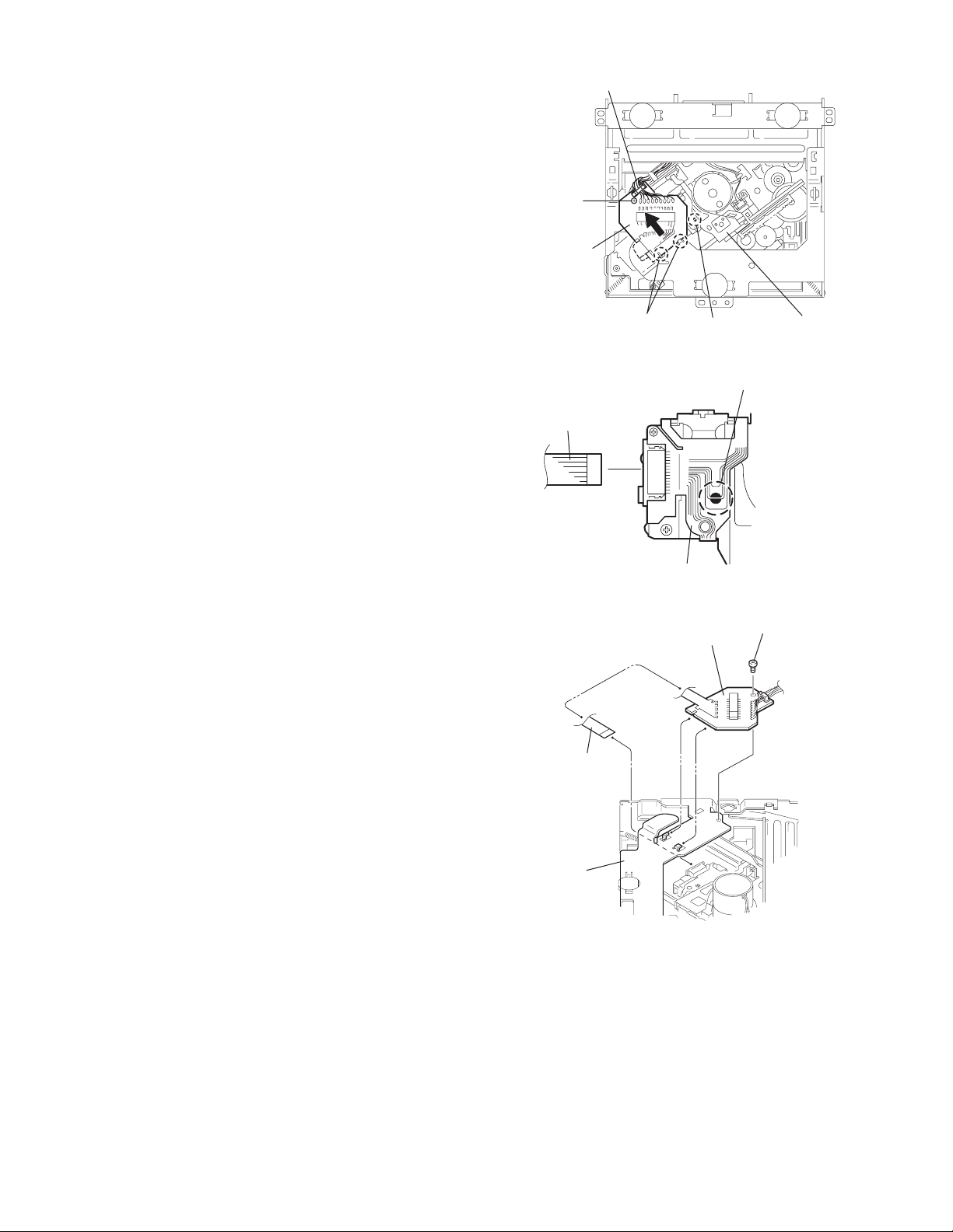
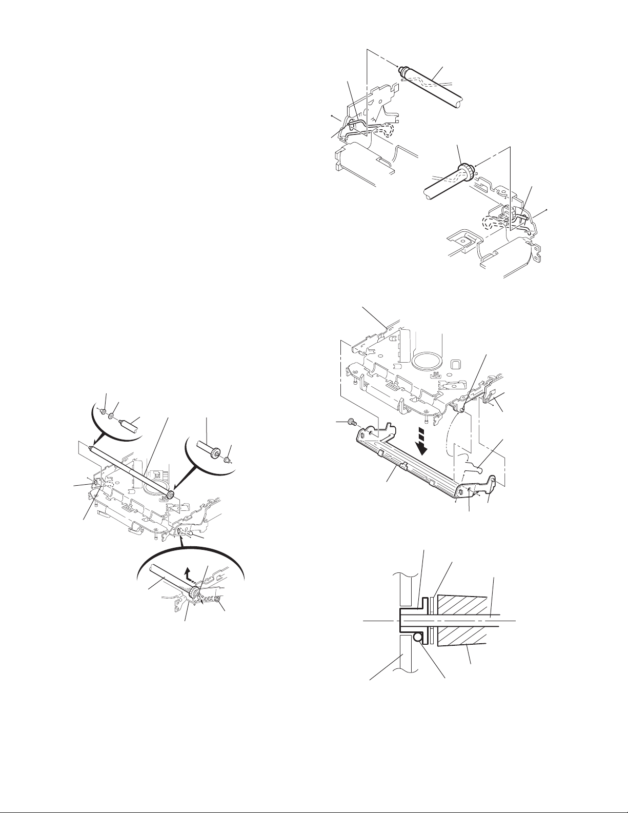
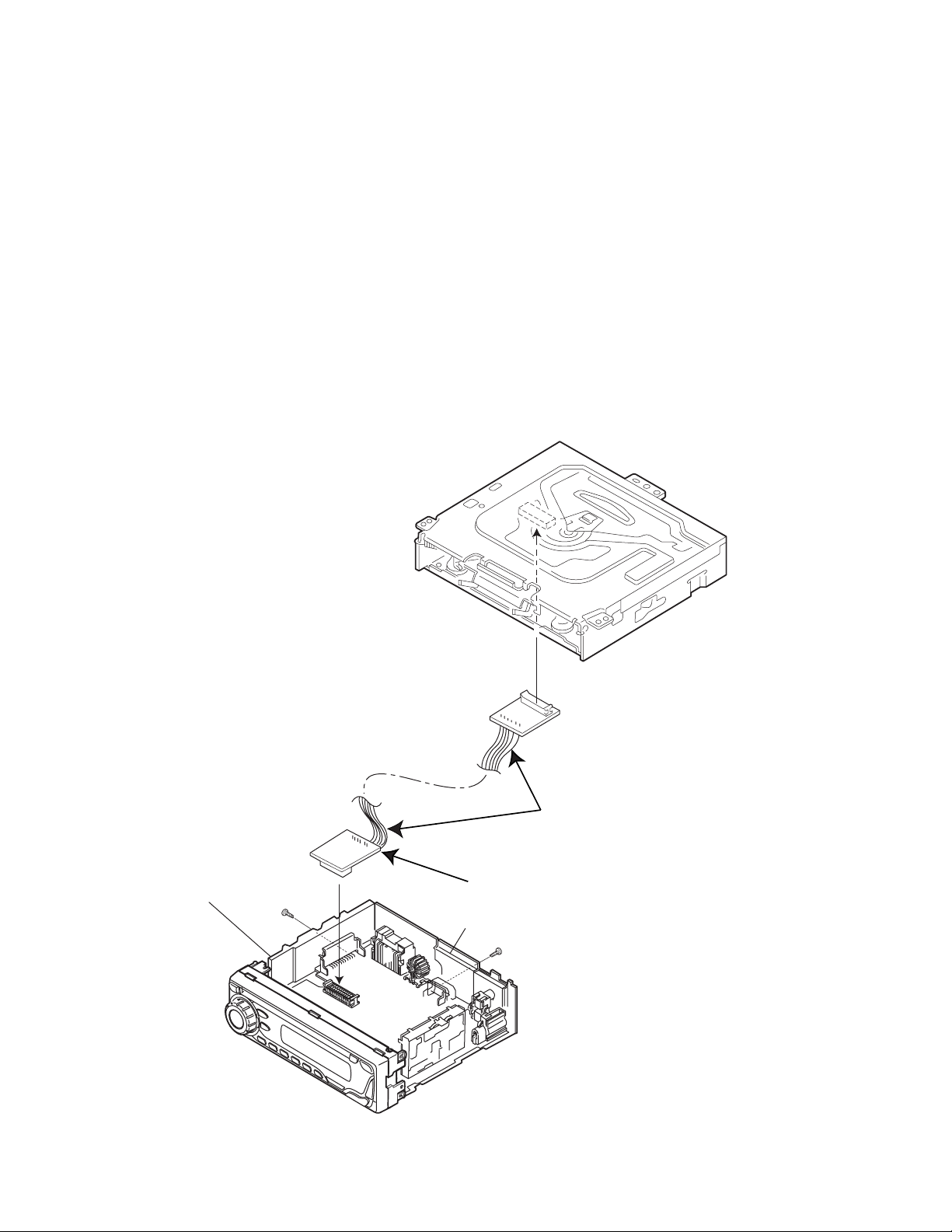
3.2.2 Removing the connector board
(See Figs.3 to 5)
CAUTION:
Before disconnecting the flexible wire from the pickup, solder
the short-circuit point on the pickup. No observance of this instruction may cause damage of the pickup.
(1) Remove the screw B fixing the connector board.
(2) Solder the short-circuit point on the connector board.
(3) Disconnect the flexible wire from the pickup.
(4) Move the connector board in the direction of the arrow to
release the two joints b.
(5) Unsolder the wire on the connector board if necessary.
CAUTION:
Unsolder the short-circuit point after reassembling.
B
Connector board
Flexible wire
Wires
Joints b
Short-circuit point
Fig.3
Short-circuit point
(Soldering)
Pickup
Flexible wire
Frame
Pickup
Fig.4
B
Connector board
Fig.5
1-10 (No.MA111)
Page 11
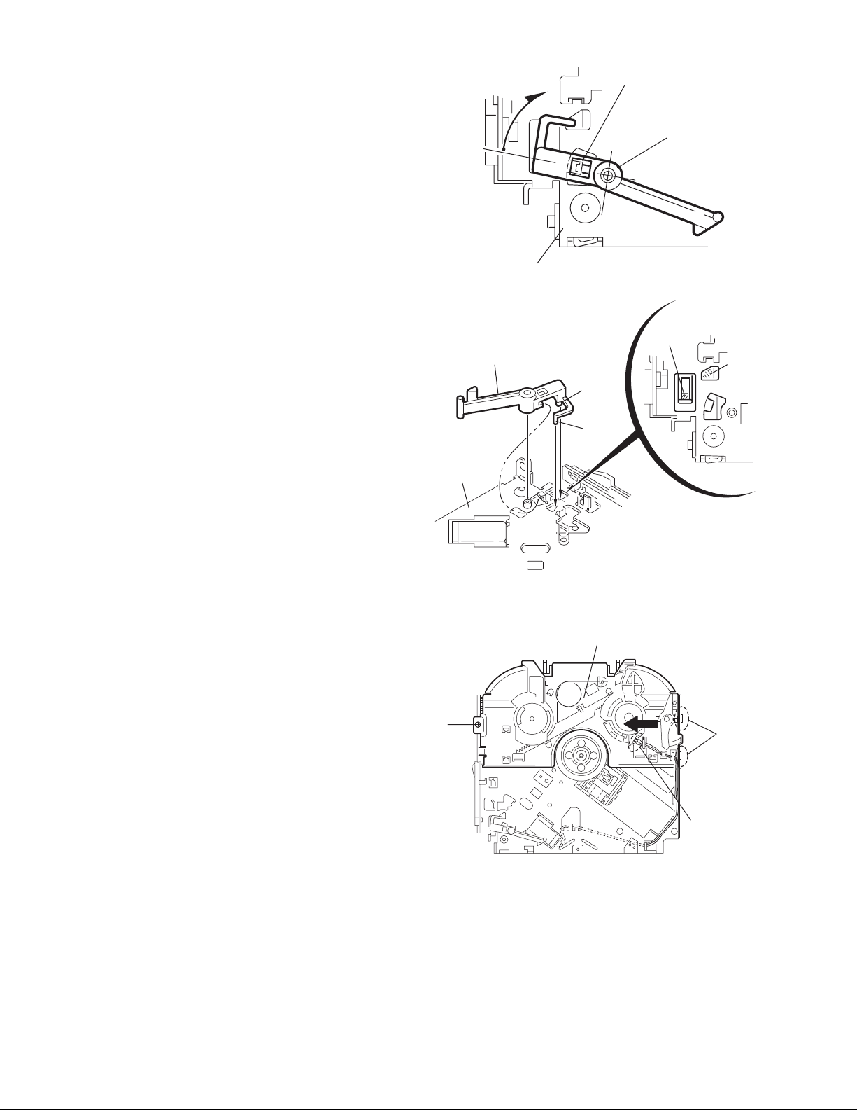
3.2.3 Removing the DET switch
(See Figs.6 and 7)
(1) Extend the two tabs c of the feed sw. holder and pull out
the switch.
(2) Unsolder the DET switch wire if necessary.
Connector
board
DET switch
DET switch
Pickup
Fig.6
Tab c
DET switch wire
Tab c
Feed sw. holder
Fig.7
(No.MA111)1-11
Page 12
3.2.4 Removing the chassis unit
r
(See Figs.8 and 9)
• Prior to performing the following procedure, remove the top
cover and connector board.
(1) Remove the two suspension springs (L) and (R) attaching
the chassis unit to the frame.
CAUTION:
• The shape of the suspension spring (L) and (R) are different. Handle them with care.
• When reassembling, make sure that the three shafts
on the underside of the chassis unit are inserted to the
dampers certainly.
Suspension spring (R)
Chassis unit
Suspension spring (L)
Frame
Suspension spring (R)
Chassis unit
Shafts
Damper
Damper
Suspension spring (L)
Fig.8
Shaft
Dampe
Frame
Fig.9
1-12 (No.MA111)
Page 13
3.2.5 Removing the clamper assembly
(See Figs.10 and 11)
• Prior to performing the following procedure, remove the top
cover.
(1) Remove the clamper arm spring.
(2) Move the clamper assembly in the direction of the arrow to
release the two joints d.
Clamper arm
spring
Joint d
Joint d
Clamper assembly
Fig.10
Clamper arm spring
Chassis rivet
assembly
Joint d
Clamper
assembly
Chassis rivet assembly
Fig.11
Joint d
(No.MA111)1-13
Page 14
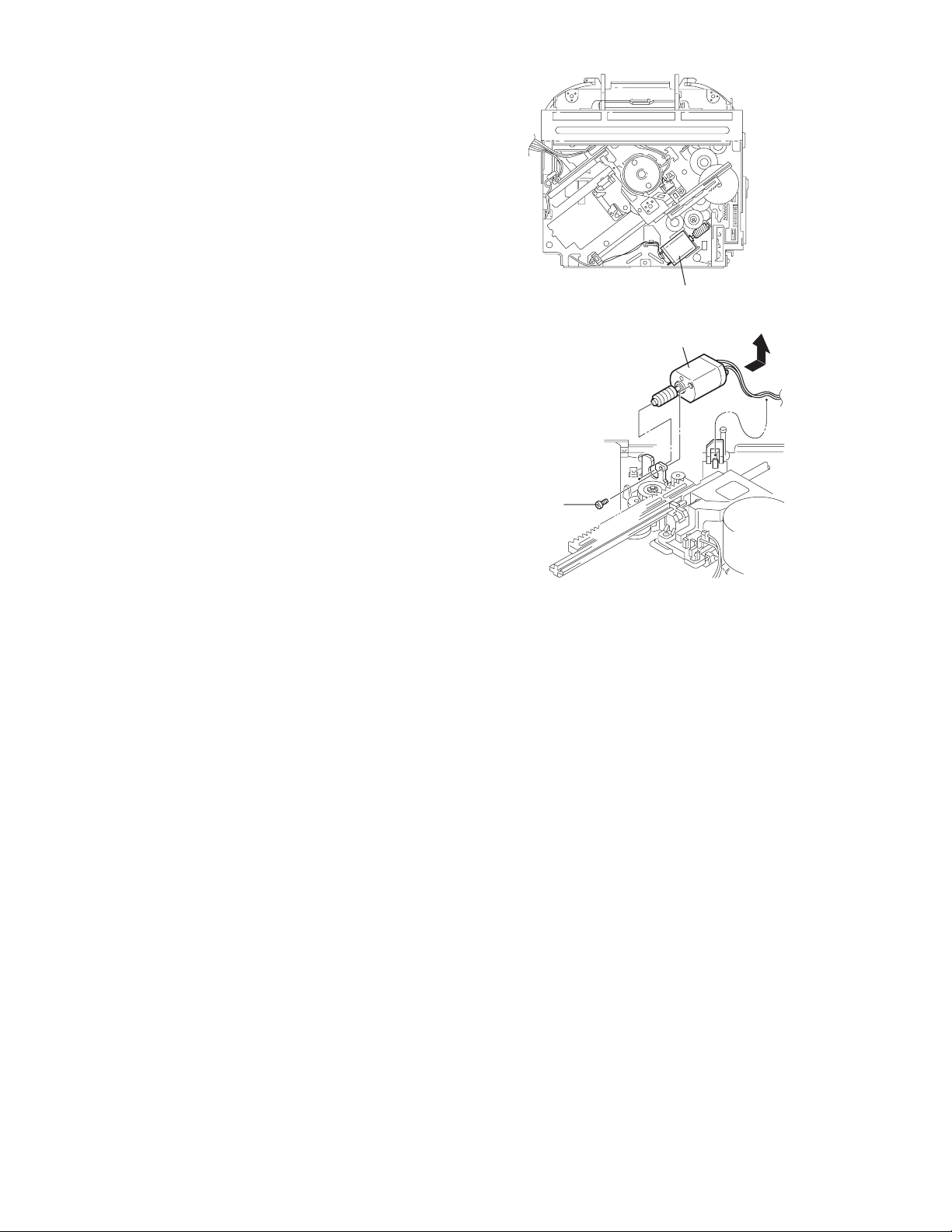
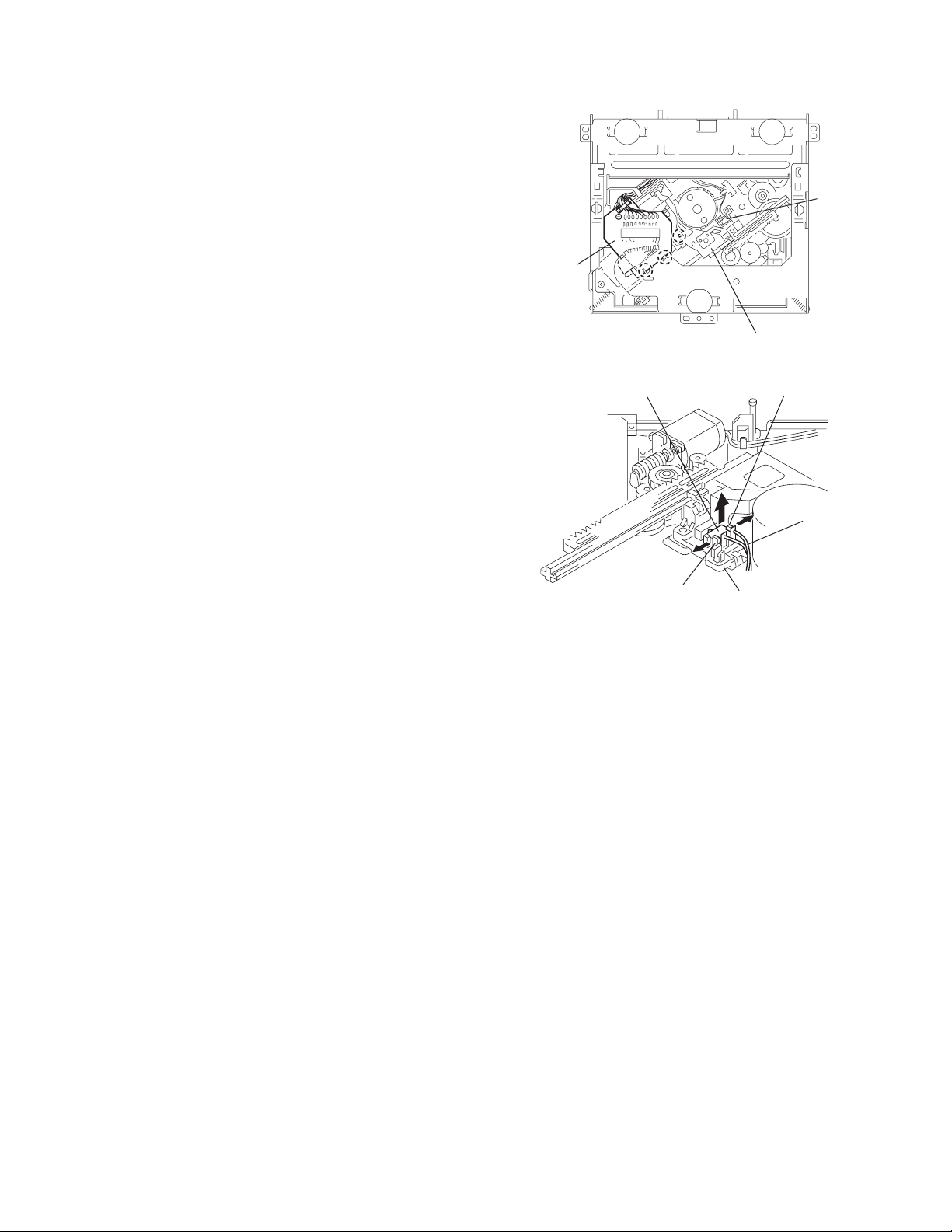
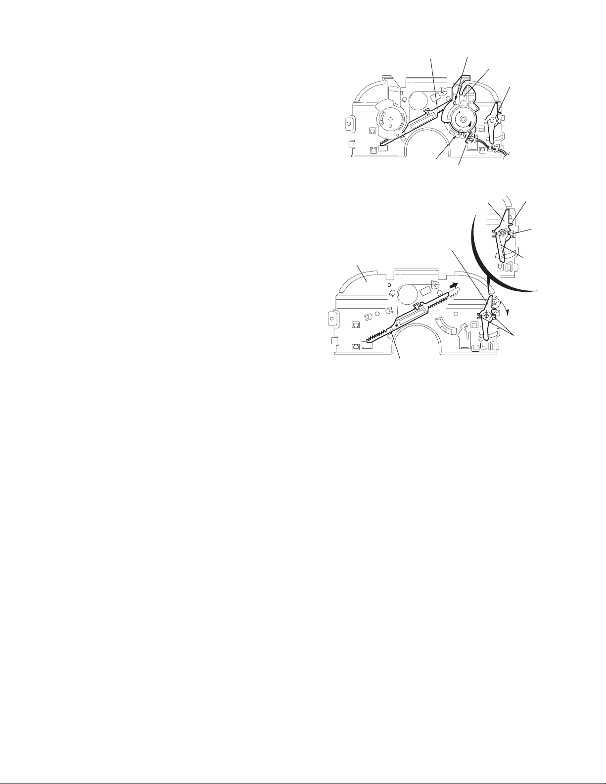
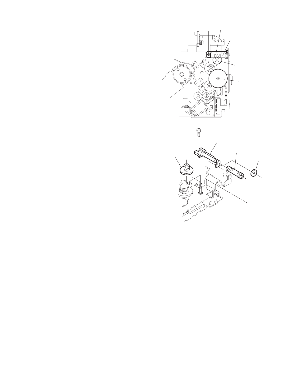
3.2.6 Removing the loading / feed motor assembly
(See Figs.12 and 13)
• Prior to performing the following procedure, remove the top
cover, connector board and chassis unit.
(1) Remove the screw C and move the loading / feed motor
assembly in the direction of the arrow to remove it from the
chassis rivet assembly.
(2) Disconnect the wire from the loading / feed motor assembly
if necessary.
CAUTION:
When reassembling, connect the wire from the loading /
feed motor assembly to the flame as shown in Fig.12.
Loading / feed motor assembly
Fig.12
Loading / feed motor assembly
C
Fig.13
1-14 (No.MA111)
Page 15
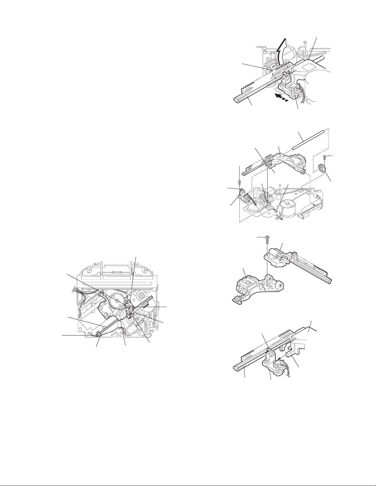
3.2.7 Removing the pickup unit
(See Figs.14 to 18)
• Prior to performing the following procedure, remove the top
cover, connector board and chassis unit.
(1) Remove the screw D and pull out the pu. shaft holder from
the pu. shaft.
(2) Remove the screw E attaching the feed sw. holder.
(3) Move the part e of the pickup unit upward with the pu. shaft
and the feed sw. holder, then release the joint f of the feed
sw. holder in the direction of the arrow. The joint g of the
pickup unit and the feed rack is released, and the feed sw.
holder comes off.
(4) Remove the pu. shaft from the pickup unit.
(5) Remove the screw F attaching the feed rack to the pickup
unit.
3.2.8 Reattaching the pickup unit
(See Figs.14 to 17)
(1) Reattach the feed rack to the pickup unit using the screw F.
(2) Reattach the feed sw. holder to the feed rack while setting
the joint g to the slot of the feed rack and setting the part f
of the feed rack to the switch of the feed sw. holder correctly.
(3) As the feed sw. holder is temporarily attached to the pickup
unit, set to the gear of the joint g and to the bending part of
the chassis (joint h) at a time.
CAUTION:
Make sure that the part i on the underside of the feed
rack is certainly inserted to the slot j of the change lock
lever.
(4) Reattach the feed sw. holder using the screw E.
(5) Reattach the pu. shaft to the pickup unit. Reattach the pu.
shaft holder to the pu. shaft using the screw D.
Feed sw. holder
Joint f
Joint g
Feed sw.
holder
Part e
Feed rack
Part i
E
Pickup unit
Slot j
F
Fig.15
Pu. shaft
Pickup unit
Joint f
Joint h
Fig.16
Feed rack
Pickup unit
Feed sw. holder
D
Pu. shaft
holder
Pu. shaft
D
Pu. shaft holder
Pickup unit
Fig.14
Part e
E
Joint g
Feed rack
Fig.17
Pickup unit
Joint g
Joint f
Feed sw. holder
Fig.18
(No.MA111)1-15
Page 16
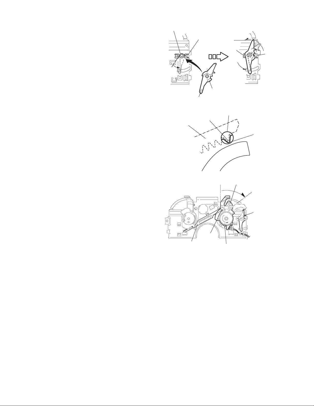
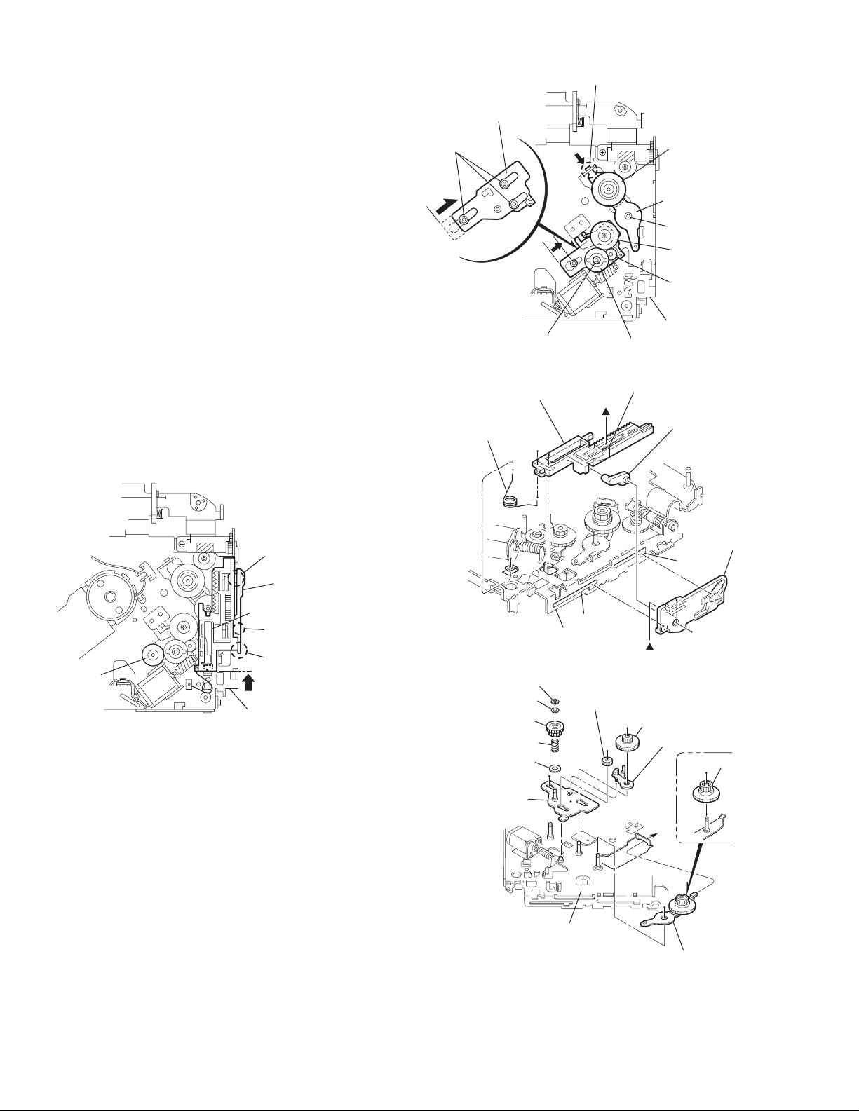
3.2.9 Removing the trigger arm
r
(See Figs.19 and 20)
• Prior to performing the following procedure, remove the top
cover, connector board and clamper unit.
(1) Turn the trigger arm in the direction of the arrow to release
the joint k and pull out upward.
CAUTION:
When reassembling, insert the part m and n of the trigger
arm into the part p and q at the slot of the chassis rivet
assembly respectively and join the joint k at a time.
Chassis rivet assembly
Trigger arm
Chassis rivet
assembly
Joint k
Trigger arm
Fig.19
Part p
Part q
Part m
Part n
3.2.10 Removing the top plate assembly
(See Fig.21)
• Prior to performing the following procedure, remove the top
cover, connector board, chassis unit, and clamper assembly.
(1) Remove the screw H.
(2) Move the top plate assembly in the direction of the arrow to
release the two joints r.
(3) Unsolder the wire marked s if necessary.
H
Fig.20
Top plate assembly
Joints
s
Fig.21
1-16 (No.MA111)
Page 17
3.2.11 Removing the mode sw. / select lock arm
(See Figs.22 and 23)
• Prior to performing the following procedure, remove the top
plate assembly.
(1) Bring up the mode sw. to release from the link plate (joint t)
and turn in the direction of the arrow to release the joint u.
(2) Unsolder the wire of the mode sw. marked s if necessary.
(3) Turn the select lock arm in the direction of the arrow to re-
lease the two joints v.
(4) The select lock arm spring comes off the select lock arm at
the same time.
Top plate
Link plate
Joint u
Joint t
s
Fig.22
Select lock arm
Select lock arm
Mode sw.
Select lock arm
Top plate
Hook w
Select lock
arm spring
Link plate
Joints v
Fig.23
(No.MA111)1-17
Page 18
3.2.12 Reassembling the mode sw. / select lock arm
(See Figs.24 to 26)
REFERENCE:
Reverse the above removing procedure.
(1) Reattach the select lock arm spring to the top plate and set
the shorter end of the select lock arm spring to the hook w
on the top plate.
(2) Set the other longer end of the select lock arm spring to the
boss x on the underside of the select lock arm, and join the
select lock arm to the slots (joint v). Turn the select lock
arm as shown in the figure.
(3) Reattach the mode sw. while setting the part t to the first
peak of the link plate gear, and join the joint u.
CAUTION:
When reattaching the mode sw., check if the points y and
z are correctly fitted and if each part operates properly.
Select lock arm spring
Hook w
Joint v
Joint v
Select lock arm
Boss x
Fig.24
Joint t
Point y
Link plate
Point z
Link plate
Fig.25
Mode sw.
Select
lock arm
Joint t
Joint u
Fig.26
1-18 (No.MA111)
Page 19
3.2.13 Removing the select arm R / link plate
(See Figs.27 and 28)
• Prior to performing the following procedure, remove the top
plate assembly.
(1) Bring up the select arm R to release from the link plate
(joint a') and turn as shown in the figure to release the two
joints b' and joint c'.
(2) Move the link plate in the direction of the arrow to release
the joint d'. Remove the link plate spring at the same time.
REFERENCE:
Before removing the link plate, remove the mode sw..
Select arm R
Joint b'
Link plate spring
Joint c'
Joint a'
Link plate
Joint b'
Fig.27
Joint r
3.2.14 Reattaching the Select arm R / link plate
(See Figs.29 and 30)
REFERENCE:
Reverse the above removing procedure.
(1) Reattach the link plate spring.
(2) Reattach the link plate to the link plate spring while joining
them at joint d'.
(3) Reattach the joint a' of the select arm R to the first peak of
the link plate while joining the two joints b' with the slots.
Then turn the select arm R as shown in the figure. The top
plate is joined to the joint c'.
CAUTION:
When reattaching the select arm R, check if the points e'
and f' are correctly fitted and if each part operates properly.
Top plate
Select arm R
Joint b'
Joint d'
Link plate
Fig.28
Link plate spring
Joint c'
Joint d'
Joint b'
Joint a'
Fig.29
Joint a'
Point e'
Link plate
Point f'
Fig.30
(No.MA111)1-19
Page 20
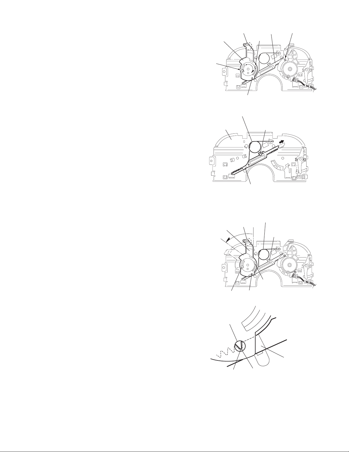
3.2.15 Removing the loading roller assembly
(See Figs.31 to 33)
• Prior to performing the following procedure, remove the
clamper assembly and top plate assembly.
(1) Push inward the loading roller assembly on the gear side
and detach it upward from the slot of the joint g' of the lock
arm rivet assembly.
(2) Detach the loading roller assembly from the slot of the joint
h' of the lock arm rivet assembly.
Roller guide
spring
Part k'
Loading roller assembly
Loading roller assembly
The roller guide comes off the gear section of the loading
roller assembly.
Remove the roller guide and the HL washer from the shaft
of the loading roller assembly.
(3) Remove the screw J attaching the lock arm rivet assembly.
(4) Push the shaft at the joint i' of the lock arm rivet assembly
inward to release the lock arm rivet assembly from the slot
of the L side plate.
(5) Extend the lock arm rivet assembly outward and release
the joint j' from the boss of the chassis rivet assembly. The
roller guide springs on both sides come off at the same
time.
CAUTION:
When reassembling, reattach the left and right roller
guide springs to the lock arm rivet assembly before reattaching the lock arm rivet assembly to the chassis rivet
assembly. Make sure to fit the part k' of the roller guide
spring inside of the roller guide. (Refer to Fig.34.)
Roller guide
HL washer
Loading roller assembly
Roller guide
Chassis rivet assembly
J
Roller guide
spring
Fig.32
Boss
L side plate
Roller guide spring
Joint h'
Roller guide spring
Loading roller assembly
Joint g'
Lock arm rivet assembly
Fig.31
Roller guide spring
Roller guide spring
Lock arm rivet assembly
Lock arm rivet assembly
Joint i'
Part j'
Fig.33
Roller guide
HL washer
Roller shaft assembly
Loading roller
Roller guide spring
Fig.34
1-20 (No.MA111)
Page 21
3.2.16 Removing the loading gear 5, 6 and 7
(See Figs.35 and 36)
• Prior to performing the following procedure, remove the top
cover, chassis unit, pickup unit and top plate assembly.
(1) Remove the screw K attaching the loading gear bracket.
The loading gear 6 and 7 come off the loading gear bracket.
(2) Pull out the loading gear 5.
K
Loading gear bracket
K
Loading gear 6
Loading gear 5
Loading gear 3
Fig.35
Loading gear bracket
Loading gear 5
Loading gear 6
Loading gear 7
Fig.36
(No.MA111)1-21
Page 22
3.2.17 Removing the gears
(See Figs.37 to 40)
• Prior to performing the following procedure, remove the top
cover, chassis unit, top plate assembly and pickup unit.
• Pull out the loading gear 3. (See Fig.35.)
(1) Pull out the feed gear.
(2) Move the loading plate assembly in the direction of the ar-
row to release the L side plate from the two slots m' of the
chassis rivet assembly. (See Fig.37.)
(3) Detach the loading plate assembly upward from the chas-
sis rivet assembly while releasing the joint n'. Remove the
slide hook and loading plate spring from the loading plate
assembly.
(4) Pull out the loading gear 2 and remove the change lock le-
ver.
(5) Remove the E ring and washer attaching the changer gear
2.
(6) The changer gear 2, change gear spring and adjusting
washer come off.
(7) Remove the loading gear 1.
(8) Move the change plate rivet assembly in the direction of the
arrow to release from the three shafts of the chassis rivet
assembly upward. (See Fig.38.)
(9) Detach the loading gear plate rivet assembly from the shaft
of the chassis rivet assembly upward while releasing the
joint p'. (See Figs.38 and 40.)
(10) Pull out the loading gear 4.
Change plate
rivet assembly
Shafts
E ring
Loading plate assembly
Loading plate spring
Joint p'
Loading gear 4
Loading gear plate
rivet assembly
Shaft
Loading gear 2
Loading gear 1
Chassis rivet assembly
Change gear 2
Fig.38
Joint n'
Slide hook
Feed gear
Fig.37
Slot m'
L side plate
Loading plate assembly
Joint n'
Slot m'
Chassis rivet assembly
Chassis rivet assembly
E ring
Washer
Change gear 2
Change gear spring
Adjusting washer
Change plate
rivet assembly
Chassis rivet assembly
L side plate
Slot m'
Slot m'
Fig.39
Loading gear 1
Loading gear 2
Change lock lever
Loading gear 4
1-22 (No.MA111)
Loading gear plate rivet assembly
Fig.40
Page 23
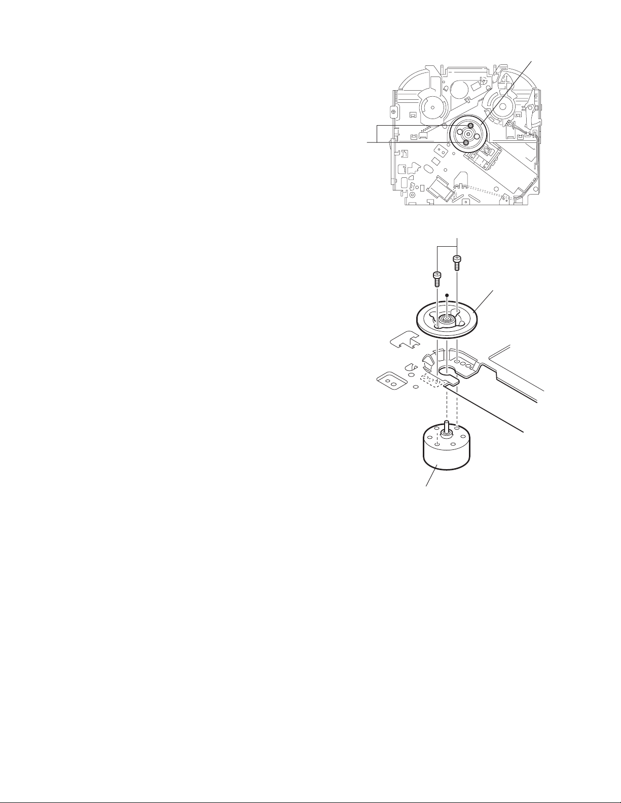
3.2.18 Removing the turn table / spindle motor
(See Figs.41 and 42)
• Prior to performing the following procedure, remove the top
cover, connector board, chassis unit and clamper assembly.
(1) Remove the two screws L attaching the spindle motor as-
sembly through the slot of the turn table on top of the body.
(2) Unsolder the wire on the connector board if necessary.
Turn table
L
Fig.41
L
Turn table
Spindle motor
Fig.42
(No.MA111)1-23
Page 24
SECTION 4
ADJUSTMENT
4.1 Adjustment method
Test instruments required for adjustment
(1) Digital oscilloscope (100MHz)
(2) Electric voltmeter
(3) Digital tester
(4) Tracking offset meter
(5) Test Disc JVC :CTS-1000
(6) Extension cable for check
EXTSH002-22P × 1
Standard volume position
Balance and Bass &Treble volume : lndication"0"
Loudness : OFF
How to connect the extension cable for adjusting
Caution:
Be sure to attach the heat sink and rear bracket onto the power amplifier IC and regulator IC respectively, before supply the power.
If voltage is applied without attaching these parts, the power amplifier IC and regulator IC will be destroyed by heat.
Standard measuring conditions
Power supply voltage DC14.4V(10.5 to 16V)
Load impedance 20KΩ(2 Speakers connection)
Output Level Line out 2.0V (Vol. MAX)
Dummy load
Exclusive dummy load should be used for AM,and FM. For FM
dummy load,there is a loss of 6dB between SSG output and
antenna input.The loss of 6dB need not be considered since
direct reading of figures are applied in this working standard.
1-24 (No.MA111)
Heat sink
Extension cable
EXTSH002-22P
Rear bracket
Page 25
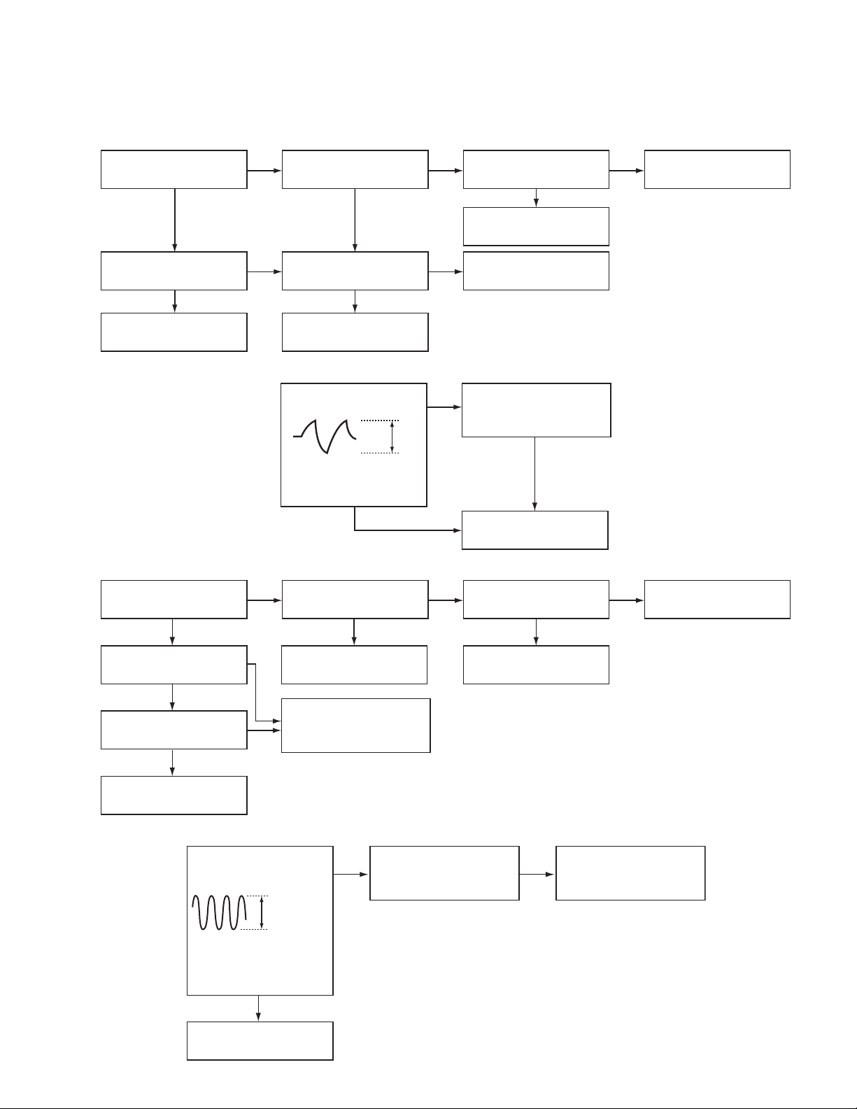
5.1 Feed section
SECTION 5
TROUBLESHOOTING
Is the voltage output at
IC561 pin 22 5v or 0V
YES
Is 4V present at both
sides of the feed motor?
YES
Check the feed motor.
5.2 Focus section
5.3 Spindle section
NO
Is the wiring for IC561
pin 22 correct?
NO
Is 6V or 2V present at
IC541 pins 4 and 5?
Check IC541.
When the lens is
moving:
Does the S-search
waveform appear at
IC541 pins 8 and 9?
NO
NO
YES
4V
YES
YES
NO
Is 5V present at IC541
pin 27?
Check the vicinity of
IC561.
Check the feed motor
connection wiring.
Check the circuits in
the vicinity of IC541
pins 15 and 16.
Check the pickup and
its connections.
NO
Check CD 8V.
YES
YES
Is the disk rotated?
YES
Does the RF signal
appear at TP RF?
YES
Is the RF waveform
at TP RF distorted?
YES
Proceed to the Tracking
section
5.4 Tracking section
When the disc is rotated
at first:
Is the tracking error
signal output at TP TE?
NO
Is 4V present between
IC541 pins 6 and 7?
Check the spindle motor
and its wiring.
NO
Check the circuits in
the vicinity of IC501
or the pickup.
NO
NO
Approx. 1.2V
NO
YES
Check the circuits in
the vicinity of IC501
pins 25 and 26.
Is 4V present at IC561
pins 24 and 25?
YES
Check the vicinity of
IC541
NO
Check the pickup and
its connections.
NO
Check IC561.
YES
Check IC561.
(No.MA111)1-25
Page 26
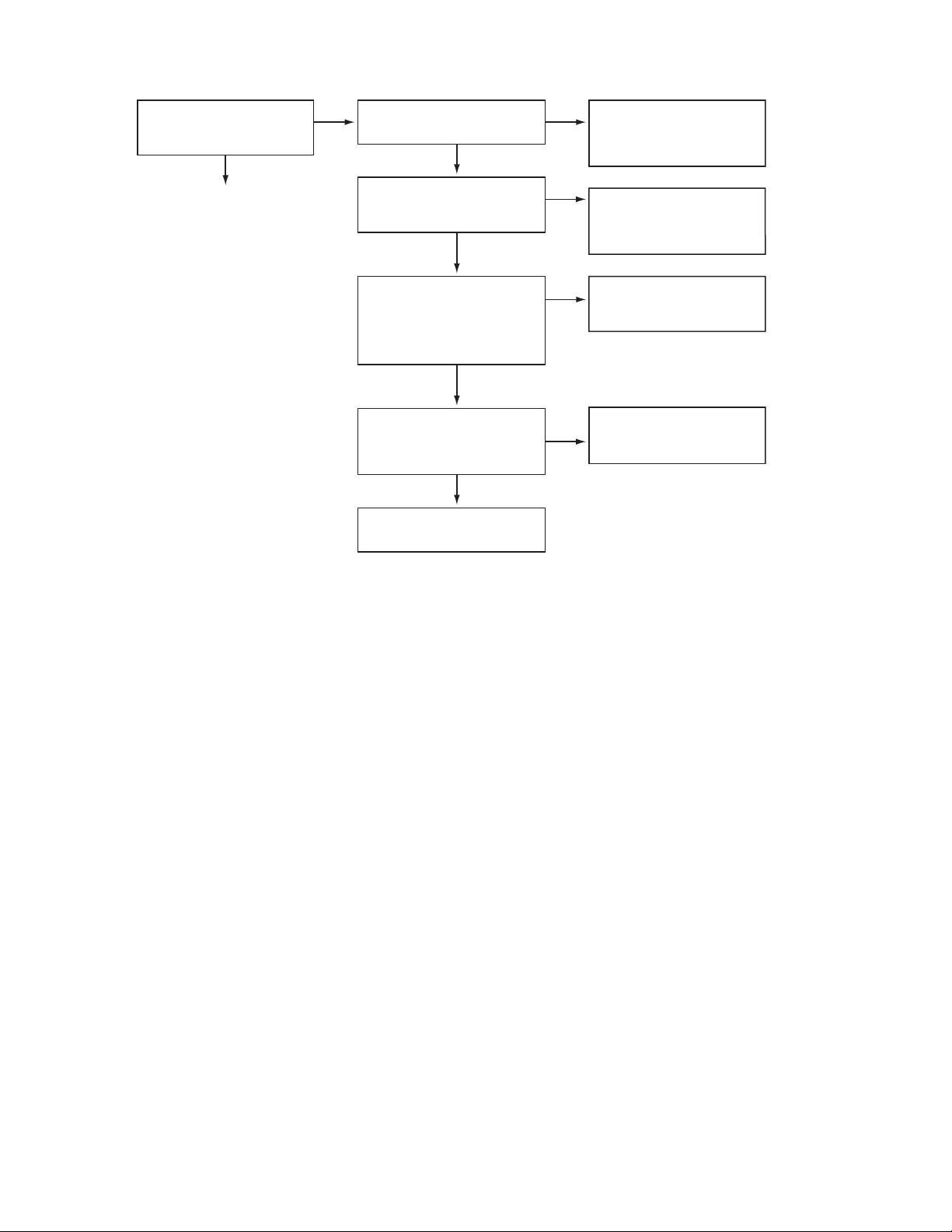
5.5 Signal proccessing section
Is the sound output from
both channels (L, R)?
YES
Normal
No sound from either
channel.
YES
Is 9V present at IC301 pin
31?
YES
NONO
Compare the L-ch and
R-ch to locate the
defctive point.
NO
Check the viciniyt of the
Q321 audio power
supply.
Is the audio signal
(including sampling output
components) output to
IC151 pins 1 and 7 during
playback?
YES
Is the audio signal output
at IC301 pins 3 and 30
during playback?
YES
Check the muting circuit.
NO
NO
Check IC151 and its
peripheral circuits.
Check IC301 and its
peripheral circuits.
1-26 (No.MA111)
Page 27
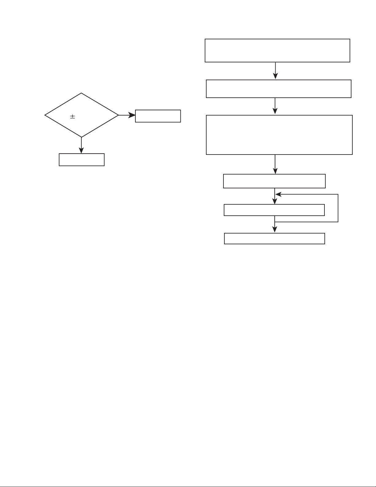
5.6 Maintenance of laser pickup
(1) Cleaning the pick up lens
Before you replace the pick up, please try to clean the lens
with a alcohol soaked cotton swab.
(2) Life of the laser diode
When the life of the laser diode has expired, the following
symptoms will appear.
• The level of RF output (EFM output: amplitude of eye
pattern) will be low.
5.7 Replacement of laser pickup
Turn off the power switch and,disconnect the
power cord from the ac outlet.
Replace the pickup with a normal one.(Refer
to "Pickup Removal" on the previous page)
Is RF output
1.0 0.35Vp-p?
NO
Replace it.
YES
O.K
(3) Semi-fixed resistor on the APC PC board
The semi-fixed resistor on the APC printed circuit board
which is attached to the pickup is used to adjust the laser
power.Since this adjustment should be performed to match
the characteristics of the whole optical block, do not touch
the semi-fixed resistor.
If the laser power is lower than the specified value, the laser diode is almost worn out, and the laser pickup should
be replaced. If the semi-fixed resistor is adjusted while the
pickup is functioning normally, the laser pickup may be
damaged due to excessive current.
Plug the power cord in,and turn the power on.
At this time,check that the laser emits for
about 3seconds and the objective lens moves
up and down.
Note: Do not observe the laser beam directly.
Play a disc.
Check the eye-pattern at TP1.
Finish.
(No.MA111)1-27
Page 28
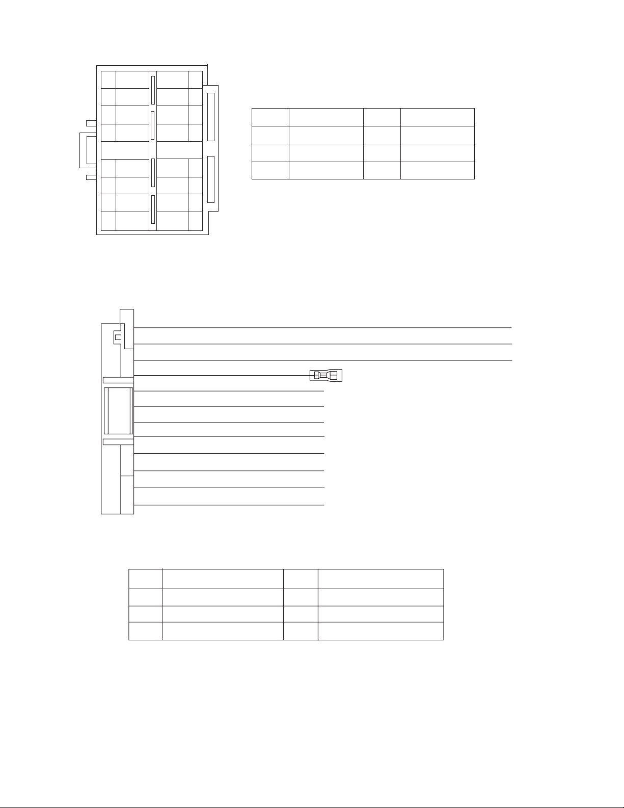
5.8 16 PIN CORD DIAGRAM
8
7
6
BL/WH
5
4
3
2
1
BK
RD
NC
WH
GN
VI
GY
WH/BK
GN/BK
GY/BK
16 YL
8 BK
7 RD
5 BL/WH REMOTE
4 WH
12 WH/BK
3 GN
11 GN/BK RL-
2 VI RR+
10 VI/BK
1 GY FR+
YL
NC
NC
NC
VI/BK
16
15
14
13
12
11
10
9
MEMORY
GND
ACC
FL+
FL-
RL+
RR-
BK
RD
BL
WH
Black
Red
Blue
White
GN
VI
GY
YL
Green
Violet
Gray
Yellow
1-28 (No.MA111)
9 GY/BK
RR
FR
FL
RL
Rear Right
Front Right
Front Left
Rear Left
FR-
REMOTE
ACC
MEMORY
GND
Remote out
ACC Line
Memory Backup Battery +
Ground
Page 29

(No.MA111)1-29
Page 30

Victor Company of Japan, Limited
AV & MULTIMEDIA COMPANY CAR ELECTRONICS CATEGORY 10-1,1chome,Ohwatari-machi,Maebashi-city,371-8543,Japan
(No.MA111)
Printed in Japan
VPT
Page 31

CD RECEIVER KD-AR260/KD-G210
ENGLISH
RECEPTOR CON CD KD-AR260/KD-G210
RECEPTEUR CD KD-AR260/KD-G210
SOUND
ATT
U
SOURCE
F
R
D
VOL
VOL
SOUND
ATT
U
SOURCE
F
R
D
VOL
VOL
• This unit is equipped with the display demonstration. To cancel it, see page 8.
• Esta unidad está equipada con demostración en la pantalla. Para cancelarla, consulte la página 8.
• Cet appareil est équipé d’une fonction de démonstration des affichages. Pour l’annuler, référezvous à la page 8.
For installation and connections, refer to the separate manual.
Para la instalación y las conexiones, refiérase al manual separado.
Pour l’installation et les raccordements, se référer au manuel séparé.
For customer Use:
Enter below the Model No. and
Serial No. which are located on
INSTRUCTIONS
MANUAL DE INSTRUCCIONES
MANUEL D’INSTRUCTIONS
the top or bottom of the
cabinet. Retain this information
for future reference.
Model No.
Serial No.
GET0246-001A
ESPAÑOL
FRANÇAIS
[J]
Page 32

FRANÇAIS
IMPORTANT POUR PRODUITS LASER
1. PRODUIT LASER CLASSE 1
2. ATTENTION: N’ouvrez pas le couvercle supérieur. Il n’y a aucune pièce réparable par l’utilisateur à
l’intérieur de l’appareil; confiez toute réparation à un personnel qualifié.
3. ATTENTION: Risque de radiations laser visible et invisible quand l’appareil est ouvert et que le
système de verrouillage ne fonctionne pas ou a été mis hors service. Évitez toute exposition directe
au rayon.
Avertissement:
Si vous souhaitez opérer l’appareil pendant que vous conduisez, assurez-vous de bien regarder devant vous afin
de ne pas causer un accident de la circulation.
Comment réinitialiser votre autoradio
Maintenez pressées les deux touches en
même temps.
• Cette procédure réinitialise le microordinateur. Vos ajustements préréglés sont
aussi effacés.
• Si un disque est en place, il est éjecté.
Faites attention, dans ce cas, de ne pas le
faire tomber.
2
Comment forcer l’éjection d’un disque
Si un disque ne peut pas être reconnu ou ne
peut pas être éjecté par l’autoradio, forcez
l’éjection de la façon suivante.
Maintenez pressées les deux touches en
même temps.
• Si cela ne fonctionne pas, essayez de
réinitialiser l’autoradio.
• Faites attention de ne pas faire tomber le
disque quand il est éjecté.
Page 33

Merci pour avoir acheté un produit JVC. Veuillez lire attentivement toutes les instructions avant d’utiliser
l’appareil afin de bien comprendre son fonctionnement et d’obtenir les meilleures performances possibles.
TABLE DES MATIÈRES
Comment réinitialiser votre autoradio ....... 2
Comment forcer l’éjection d’un disque ...... 2
Comment utiliser la touche MODE............ 3
EMPLACEMENT DES TOUCHES .......... 4
Panneau de command .............................. 4
Télécommande ......................................... 5
Préparation de la télécommande .............. 6
FONCTIONNEMENT DE BASE ............ 7
Mise sous tension ..................................... 7
Annulation de la démonstration des
affichages ............................................... 8
Réglage de l’horloge ................................. 9
FONCTIONNEMENT DE LA RADIO ....... 10
Ecoute de la radio ..................................... 10
Mémorisation des stations ........................ 12
Accord d’une station présélectionnée ....... 13
FONCTIONNEMENT DU LECTEUR CD ... 14
Lecture d’un CD ........................................ 14
Localisation d’une plage ou d’un point
particulier sur un CD .............................. 15
Sélection des modes de lecture de CD..... 15
Interdiction de l’éjection de CD ................. 16
AJUSTEMENT DU SON .................... 17
Sélection des modes sonores préréglés
(C-EQ: égaliseur personnalisé) .............. 17
Ajustement du son .................................... 18
AUTRES FONCTIONS PRINCIPALES..... 19
Sélection du mode de gradateur ............... 19
Sélection de la commande de gain de
l’amplificateur ......................................... 19
Détachement du panneau de commande ... 20
DÉPANNAGE ................................ 21
ENTRETIEN ................................. 22
Manipulation des disques ......................... 22
SPÉCIFICATIONS........................... 23
Comment utiliser la touche MODE
Si vous appuyez sur MODE, l’appareil entre en mode de fonctions et les touches numériques
peuvent être utilisées comme touches de fonction.
Ex.: Quand la touche numérique 2 fonctionne comme touche MO (monaural).
FRANÇAIS
Indicateur de durée restante
Pour utiliser de nouveau ces touches comme touches numériques après avoir appuyer sur
MODE, attendez 5 secondes sans appuyer sur aucune touche, jusqu’à ce que le mode de
fonctions soit annulé.
• Appuyer de nouveau sur MODE annule aussi le mode de fonctions.
AVANT D’UTILISER L’APPAREIL
*
Par sécurité....
• N’augmentez pas trop le volume car cela bloquerait
les sons de l’extérieur rendant la conduite
dangereuse.
• Arrêtez la voiture avant de réaliser toute opération
compliquée.
*
Température à l’intérieur de la voiture....
Si votre voiture est restée garée pendant longtemps
dans un climat chaud ou froid, attendez que la
température à l’intérieur de la voiture redevienne
normale avant d’utiliser l’appareil.
3
Page 34

EMPLACEMENT DES TOUCHES
Panneau de command
Fenêtre d’affichage
FRANÇAIS
1 Touche (attente en service/sourdine)
2 Touche SEL (sélection)
3 Touche FM/AM
4 Touche CD
5 La fente d’insertion
6 Fenêtre d’affichage
7 Touche 0 (éjection)
8 Capteur de télécommande
9 Touche EQ (égaliseur)
p Touche 5 (haut)
Touche ¡ (avance rapide)
q Molette de commande
w Touches numériques
e Touche MO (monaural)
r Touche SSM (Mémorisation automatique des
meilleures stations)
t Touche RPT (répétition)
y Touche RND (aléatoire)
u Touche MODE
i Touche DISP (affichage)
o Touches
; Touche (déblocage du panneau de
commande)
4/¢
4
a Touche ∞ (bas)
Touche 1 (retour rapide)
Fenêtre d’affichage
s Indicateurs de réception du tuner
—MO (monaural), ST (stéréo)
d Indicateur CD
f Indicateur RND
g Indicateur RPT (répétition)
h Indicateur LOUD (contour)
j Indicateur EQ (égaliseur)
k Indicateurs du mode sonore (C-EQ: égaliseur
personnalisé)—ROCK, CLASSIC, POPS, HIP
HOP, JAZZ, USER
l Affichage principal
/ Affichage de la source
Indicateur du niveau de volume
(disque aléatoire)
Page 35

Télécommande
RM-RK50
SOUND
ATT
U
SOURCE
R
VOL
1 • Met l’appareil sous tension si vous appuyez
sur cette touche quand l’appareil est hors
tension.
• Maintenez pressée jusqu’à ce que
“SEE YOU” apparaisse sur l’affichage pour
mettre l’appareil hors tension.
• Appuyez brièvement sur cette touche pour
couper le volume momentanément.
Appuyez de nouveau le rétablir.
F
D
VOL
4 Fonctionne de la même façon que la molette
de commande de l’appareil principal.
Remarque:
Ces touches ne sont pas utilisées pour
ajuster “DEMO”, “CLOCK H”,
“CLOCK M”, “DIMMER” et “AMP
GAIN” (voir les pages 8, 9 et 19).
5 Sélectionne le mode sonore (C-EQ: égaliseur
personnalisé).
Chaque fois que vous appuyez sur la touche,
le mode sonore (C-EQ) change.
6 Sélectionner la source.
Chaque fois que vous appuyez sur la touche,
la source change.
7 • Recherche des stations en écoutant la
radio.
• Fait défiler rapidement en avant ou en
inverse la plage si est maintenue pressée
en écoutant le CD.
• Saute au début de plage suivante ou revient
au début des plages courante (ou
précédentes) si est brièvement pressée en
écoutant le CD.
FRANÇAIS
2 Choisit la bande lors de l’écoute de la radio.
Chaque fois que vous appuyez sur la touche,
la bande change.
3 Choisit les stations préréglées lors de l’écoute
de la radio.
Chaque fois que vous appuyez sur la touche,
le numéro de station préréglée augmente et
la station choisie est accordée.
5
Page 36

Préparation de la
télécommande
Avant d’utiliser la télécommande:
• Pointez la télécommande directement sur le
capteur de télécommande de l’appareil
principal. Assurez-vous qu’il n’y a pas
d’obstacle entre les deux.
Capteur de télécommande
FRANÇAIS
• Ne pas exposer la télécommande à un
éclairage puissant (en plein soleil ou un
éclairage artificiel).
Mise en place de la pile
Lorsque la portée ou l’efficacité de la
télécommande diminue, remplacez la pile.
1. Retirez le porte-pile.
1) Poussez le porte-pile dans la direction de
la flèche en utilisant la pointe d’un
stylo-bille ou un objet similaire.
2) Retirez le porte-pile.
3. Remettez le porte-pile en place.
Insérez le porte-pile en le poussant jusqu’à
ce que vous entendiez un déclic.
(face arrière)
AVERTISSEMENT:
• Conservez la pile hors de la portée des enfants.
Si un enfant venait à avaler une pile, consultez
immédiatement un médecin.
• Ne rechargez pas, ne court-circuitez pas, de
démontez pas, ne chauffez pas la pile et ne les
jetez pas dans le feu.
Le faire, pourrait amener la pile à émettre de la
chaleur, se fragmenter ou causer un incendie.
• Ne mélangez pas la pile avec d’autres objets
métalliques.
Le faire, pourrait amener la pile à émettre de la
chaleur, se fragmenter ou causer un incendie.
• Pour vous débarrassez des pile ou les
conserver, entourez-les de ruban adhésif et
isolez-les. Ne pas le faire, pourrait amener la
pile à émettre de la chaleur, se fragmenter ou
causer un incendie.
• Ne piquez pas la pile avec une broche
métallique ou un objet similaire.
Le faire, pourrait amener la pile à émettre de la
chaleur, se fragmenter ou causer un incendie.
(face arrière)
2. Placez la pile.
Insérez la pile dans le porte-pile avec le pole
+ dirigé vers le haut de façon que la pile soit
bien fixée dans le porte-pile.
Pile bouton au
lithium (Produit
référencé: CR2025)
6
ATTENTION:
NE LAISSEZ pas la télécommande pendant
longtemps dans un endroit exposé aux rayons
directs du soleil (tel que le tableau de bord).
Sinon, elle risque d’être endommagée.
Page 37

FONCTIONNEMENT DE BASE
1
3
2
Mise sous tension
1
Mettez l’appareil sous tension.
Remarque sur le fonctionnement monotouche:
Quand vous choisissez la source à l’étape
ci-dessous, l’appareil se met automatiquement
sous tension. Vous n’avez donc pas besoin
d’appuyer d’abord sur cette touche pour mettre
l’appareil sous tension.
2
Choisissez la source.
Pour utiliser le tuner (FM ou AM),
voir les pages 10 – 13.
Pour reproduire un CD,
voir les pages 14 – 16.
3
Ajustez le volume.
4
Ajustez le son comme vous le
souhaitez. (Voir les pages 17 et 18).
Pour baisser le son instantanément
Appuyez brièvement sur pendant
l’écoute de n’importe quelle source. “ATT ”
2
commence à clignoter sur l’affichage, et le
niveau de volume est baissé instantanément.
Pour revenir au niveau de volume précédent,
appuyez de nouveau brièvement sur la touche.
• Si vous tournez la molette de commande, vous
pouvez aussi rétablir le son.
FRANÇAIS
Pour mettre l’appareil hors tension
Maintenez pressée pendant plus d’une
seconde.
“SEE YOU” apparaît et l’appareil se met hors
tension.
• Si vous mettez l’appareil hors tension lors
de l’écoute d’un CD, la lecture du CD
débutera à partir de l’endroit où elle a été
interrompue la prochaine fois que vous mettez
l’appareil sous tension.
Pour augmenter le
volume
Pour diminuer le
volume
Le niveau de volume apparaît.
Indicateur du niveau de volume
PRECAUTION sur le réglage du volume:
Les CD produisent très peu de bruit comparé avec
les autres sources. Si le niveau de volume est
ajusté, par exemple, pour le tuner, les enceintes
risquent d’être endommagées par l’augmentation
soudaine du niveau de sortie.
Par conséquent, diminuez le volume avant de
reproduire un CD et ajustez-le comme vous le
souhaitez pendant la lecture.
7
Page 38

Annulation de la
DEMO OFF
DEMO ON
démonstration des affichages
À l’expédition de l’usine, la démonstration est en
service et celle-ci démarre automatiquement
FRANÇAIS
quand aucune opération n’est effectuée pendant
environ 20 secondes.
• Il est recommandé d’annuler la démonstration
des affichages avant d’utiliser l’appareil pour la
première fois.
Pour annuler la démonstration des
affichages, suivez la procédure ci-dessous:
1
Maintenez pressée SEL (sélection)
pendant plus de 2 secondes.
“DEMO”, “CLOCK H”, “CLOCK M”,
“DIMMER”, ou “AMP GAIN” apparaît sur
l’affichage.
2
Choisissez “DEMO” s’il n’apparaît
pas sur l’affichage.
3
Choisissez “DEMO OFF”.
4
Terminez le réglage.
Pour mettre en service la démonstration des
affichages, répétez la même procédure et
choisissez “DEMO ON” à l’étape
3
.
8
Page 39

Réglage de l’horloge
Fréquence
Horloge
1
Maintenez pressée SEL (sélection)
pendant plus de 2 secondes.
“DEMO”, “CLOCK H”, “CLOCK M”,
“DIMMER”, ou “AMP GAIN” apparaît sur
l’affichage.
2
Réglez les heures.
1 Choisissez “CLOCK H” (heures) s’il
n’apparaît pas sur l’affichage.
2 Ajustez les heures.
12
4
Terminez le réglage.
Pour vérifier l’heure actuelle ou changer le
mode d’affichage
Appuyez sur DISP (affichage)
répétitivement.
Chaque fois que vous appuyez sur
la touche, le mode d’affichage
change comme suit:
• Pendant l’utilisation du tuner:
• Pendant l’utilisation du CD:
HorlogeDurée de lecture écoulée
FRANÇAIS
3
Réglez les minutes.
1 Choisissez “CLOCK M” (minutes).
2 Ajustez les minutes.
12
• Quand l’appareil est hors tension:
L’appareil se met sous tension et l’horloge
apparaît pendant 5 secondes. Puis, l’appareil
se remet hors tension.
9
Page 40

FONCTIONNEMENT DE LA RADIO
Ecoute de la radio
Vous pouvez utiliser la recherche automatique ou
l’accord manuel pour accorder une station
particulière.
FRANÇAIS
Recherche d’une station
automatiquement:
Recherche automatique
1
Choisissez la bande (FM1 – 3, AM).
Chaque fois que vous
appuyez sur la touche, la
bande change comme suit:
FM1 FM2 FM3 AM
S’allume lors de la réception d’une émission
FM stéréo de signal suffisamment for.
La bande choisie apparaît.
Remarque:
Cet appareil a trois bandes FM (FM1, FM2,
FM3). Vous pouvez utiliser n’importe laquelle
pour écouter une station FM.
2
Commencez la recherche d’une
station.
Pour rechercher des
stations de fréquences
supérieures
Pour rechercher des stations de fréquences
inférieures
Quand une station est accordée, la
recherche s’arrête.
Pour arrêter la recherche avant qu’une
station ne soit accordée, appuyez sur la même
touche que vous avez utilisée pour la recherche.
10
Page 41

Recherche manuelle d’une station:
Recherche manuelle
1
Choisissez la bande (FM1 – 3, AM).
Chaque fois que vous
appuyez sur la touche, la
bande change comme suit:
FM1 FM2 FM3 AM
Remarque:
Cet appareil a trois bandes FM (FM1, FM2,
FM3). Vous pouvez utiliser n’importe laquelle
pour écouter une station FM.
2
Maintenez pressée ¢ ou 4
jusqu’à ce que “M” (manuel) clignote
sur l’affichage.
3
Accordez une station souhaitée
pendant que “M” (manuel) clignote.
Pour accorder des stations
de fréquences supérieures
Quand une émission FM stéréo est
difficile à recevoir:
1 Appuyez sur MODE pour entrer
en mode de fonction pendant
l’écoute d’une station FM.
2 Appuyez sur MO (monaural)
pendant que “MODE” clignote
sur l’affichage, de façon que
“MONO” apparaisse sur
l’affichage.
Chaque fois que vous appuyez
sur la touche, le mode monaural
se met alternativement en et
hors service.
Indicateur MO (monaural)
Lorsque l’indicateur MO est allumé sur
l’affichage, le son que vous entendez est
monaural mais la réception est améliorée.
FRANÇAIS
Pour accorder des stations de fréquences
inférieures
• Si vous relâchez la touche, le mode
manuel est mis automatiquement hors
service après 5 secondes.
• Si vous maintenez la touche pressée, la
fréquence continue de changer (par
intervalle de 200 kHz pour la bande FM et
par intervalle de 10 kHz pour la bande
AM) jusqu’à ce que vous la relâchiez.
11
Page 42

Mémorisation des stations
Vous pouvez utiliser l’une des deux méthodes
suivantes pour mémoriser les stations reçues.
• Présélection automatique des stations FM:
SSM (Mémorisation automatique des
meilleures stations)
• Présélection manuelle des stations FM et AM
Présélection manuelle
Vous pouvez présélectionner manuellement un
maximum de 6 stations pour chaque bande
(FM1, FM2, FM3 et AM).
Ex.: Mémorisation de la station FM située à
92,5 MHz sur le numéro de présélection 1
de la bande FM1.
Présélection automatique des stations
FM: SSM
Vous pouvez présélectionner 6 stations locales
dans chaque bande FM (FM1, FM2 et FM3).
1
Choisissez le numéro de la bande
FM (FM1 – 3) où vous souhaitez
FRANÇAIS
mémoriser la station.
Chaque fois que vous
appuyez sur la touche, la
bande change comme suit:
FM1 FM2 FM3 AM
2
Appuyez sur MODE pour entrer en
mode de fonction.
3
Maintenez pressée SSM pendant
environ 2 secondes.
1
Choisissez le numéro de la bande
(FM1 – 3, AM) où vous souhaitez
mémoriser la station (dans cet
exemple, FM1).
Chaque fois que vous
appuyez sur la touche, la
bande change comme suit:
FM1 FM2 FM3 AM
2
Accordez une station (dans cet
exemple à 92,5 MHz).
Pour accorder des stations
de fréquences supérieures
Pour accorder des stations de fréquences
inférieures
3
Maintenez pressée la touche
numérique (dans cet exemple, 1)
pendant plus de 2 secondes.
“SSM” clignote, puis disparaît quand le
préréglage automatique est terminé.
Les stations locales FM avec les signaux les plus
forts sont recherchées et mémorisées
automatiquement dans le numéro de bande que
vous avez choisi (FM1, FM2 ou FM3). Ces
stations sont mémorisées sur les touches de
présélection de station—No.1 (fréquence la plus
basse) à No.6 (fréquence la plus haute).
Quand la présélection est terminée, la station
mémorisée automatiquement sur la touche de
présélection de station 1 est accordée
automatiquement.
12
Le numéro préréglé clignote pendant un
instant.
Page 43

4
Répétez la procédure ci-dessus pour
mémoriser d’autres stations sur
d’autres numéros de présélection.
Remarques:
• La station précédemment présélectionnée est
effacée quand une nouvelle station est mémorisée
sur le même numéro de présélection.
• Les stations présélectionnées sont effacées si
l’alimentation du circuit mémoire est interrompue
(par exemple, pendant le changement de la
batterie). Si cela se produit, présélectionnez de
nouveau les stations.
Accord d’une station
présélectionnée
Vous pouvez accorder facilement une station
présélectionnée.
Rappelez-vous que vous devez d’abord
mémoriser les stations. Si vous ne les avez pas
encore mémorisées, référez-vous à
“Mémorisation des stations” à les pages 12 et
13.
1
Choisissez la bande (FM1 – 3, AM).
Chaque fois que vous
appuyez sur la touche, la
bande change comme suit:
FM1 FM2 FM3 AM
2
Choisissez le numéro (1 – 6) de la
station présélectionnée souhaitée.
FRANÇAIS
Remarque:
Vous pouvez aussi utiliser les touches 5 (haut) ou ∞
(bas) sur l’appareil pour choisir les stations
présélectionnées suivantes ou précédentes.
Chaque fois que vous appuyez les touches 5 (haut)
ou ∞ (bas), les stations présélectionnées suivantes ou
précédentes sont accordées.
13
Page 44

FONCTIONNEMENT DU LECTEUR CD
Lecture d’un CD
Insérez un disque dans la fente de
d’insertion.
FRANÇAIS
Remarque sur le fonctionnement monotouche:
Si un CD se trouve déjà dans la fente d’insertion,
appuyer sur CD met l’appareil sous tension et
commence la lecture automatiquement.
Indicateur CD
Indication de la source actuelle
Durée de lecture
totale du disque
inséré
Durée de lecture
écoulée
Toutes les plages sont reproduites répétitivement
jusqu’à ce que vous arrêtiez la lecture.
L’appareil se met en
marche, tire le CD et
commence la lecture
automatiquement.
Nombre total de
plages du disque
inséré
Numéro de la
plage actuelle
Remarque:
Quand un CD est inséré à l’envers, “EJECT”
apparaît sur l’affichage et le CD est éjecté
automatiquement.
Pour arrêter la lecture et éjecter le CD
Appuyez sur 0.
La lecture du CD s’arrête et le CD est
automatiquement éjecté de la fente d’insertion.
La source change sur le tuner (vous entendez la
dernière station reçue).
• Si vous changez la source, la lecture de CD
s’arrête aussi (sans éjecter le CD).
La prochaine fois que vous choisissez “CD”
comme source, la lecture du CD commence à
partir de l’endroit où elle a été interrompue.
Remarques:
• Si le CD éjecté n’est pas retiré avant environ 15
secondes, le CD est automatiquement réinséré dans
la fente d’insertion pour le protégé de la poussière.
(Dans ce cas, la lecture du CD ne commence pas).
• Vous pouvez éjecter le CD quand l’appareil est hors
tension.
A propos du désaligement:
Un désalignement peut être la conséquence d’une
conduite sur un terrain accidenté. Cela
n’endommage pas l’appareil ni le CD, mais cela
peut être agaçant.
Nous vous recommandons d’arrêter la lecture de
CD lors d’une conduite sur un tel terrain.
14
Page 45

Localisation d’une plage ou
d’un point particulier sur un CD
Sélection des modes de
lecture de CD
Pour avancer rapidement ou inverser une
plage
Maintenez pressée ¡,
pendant la reproduction d’un
CD, pour avancer rapidement la
plage.
Maintenez pressée 1, pendant la reproduction
d’un CD, pour inverser la plage.
Pour aller aux plages suivantes ou
précédentes
Appuyez brièvement sur
lors de la reproduction d’un CD,
pour avancer jusqu'au début de
la plage suivante.
Chaque fois que vous appuyez
consécutivement sur la touche,
le début des plages suivantes est
localisé et celle-ci est reproduite.
Appuyez brièvement sur
reproduction d’un CD, pour revenir au début de la
plage actuelle.
Chaque fois que vous appuyez consécutivement
sur la touche, le début des plages précédentes est
localisé et celle-ci est reproduite.
4
lors de la
¢
Pour aller directement à une plage
particulière
Appuyez sur la touche numérique
correspondante au numéro de plage souhaité
pour commencer sa reproduction.
Pour reproduire les plages dans un ordre
aléatoire (Lecture aléatoire de disque)
Vous pouvez reproduire toutes les plages du
disque dans un ordre aléatoire.
1 Appuyez sur MODE pour entrer
en mode de fonction pendant
l’écoute d’un CD.
2 Appuyez sur RND (aléatoire)
pendant que “MODE” clignote
sur l’affichage, de façon que
“DISC RND” apparaisse sur
l’affichage.
Chaque fois que vous appuyez
sur la touche, le mode de
lecture aléatoire de disque se
met alternativement en et hors
service.
Indicateur RND
Quand la lecture aléatoire de disque est mise en
service, l’indicateur RND
l’affichage. Puis, une plage choisie aléatoirement
est reproduite.
(disque aléatoire)
s’allument sur
FRANÇAIS
• Pour choisir un numéro de plage de 1 – 6:
Appuyez brièvement sur 1 (7) – 6 (12).
• Pour choisir un numéro de plage de 7 – 12:
Maintenez pressé 1 (7) – 6 (12) pendant plus
d’une seconde.
15
Page 46

Pour reproduire les plages répétitivement
(Lecture répétée de plage)
Vous pouvez reproduire la plage actuelle
répétitivement.
1 Appuyez sur MODE pour entrer
en mode de fonction pendant
l’écoute d’un CD.
2 Appuyez sur RPT (répétition)
pendant que “MODE” clignote
sur l’affichage, de façon que
“TRK RPT” apparaisse sur
l’affichage.
Chaque fois que vous appuyez
sur la touche, le mode de
lecture répétée de plage se met
FRANÇAIS
Quand la lecture répétée de plage est mise en
service, l’indicateur RPT s’allume sur l’affichage.
Puis, la plage en cours de lecture est reproduite
répétitivement.
alternativement en et hors
service.
Indicateur RPT
Interdiction de l’éjection de CD
Vous pouvez interdire l’éjection d’un CD et le
verrouiller dans la fente d’insertion.
Tout en maintenant pressée CD,
maintenez pressée 0 pendant plus de
2 secondes.
“NO EJECT” clignote sur l’affichage pendant
environ 5 secondes, le CD est verrouillé et ne
peut plus être éjecté.
Pour annuler l’interdiction et
déverrouiller le CD
Tout en appuyant sur CD, maintenez de nouveau
pressée 0 pendant plus de 2 secondes.
“EJECT” apparaît sur l’affichage et le CD est
éjecté de la fente d’insertion.
16
Page 47

AJUSTEMENT DU SON
Sélection des modes sonores
préréglés (C-EQ: égaliseur
personnalisé)
Vous pouvez choisir un mode sonore préréglé
(C-EQ: égaliseur personnalisé) convenant à
votre genre de musique.
Choisissez le mode sonore que vous
souhaitez.
Chaque fois que vous
appuyez sur la touche, le
mode sonore change comme
suit:
CLASSICROCKUSER
JAZZ
Le modèle d’affichage change pour
chaque mode sonore sauf pour “USER”.
HIP HOP
POPS
Indication Pour: Valeurs préréglées
BAS TRE LOUD
USER (Son plat) 00 00 OFF
ROCK Musique +03 +01 ON
rock ou disco
CLASSIC Musique +01 –02 OFF
classique
POPS Musique +04 +01 OFF
légère
HIP HOP Musique +02 00 ON
funk ou rap
JAZZ Musique +02 +03 OFF
Jazz
Remarque:
Vous pouvez ajuster chaque mode sonore selon vos
préférences. Une fois que vous avez réalisé un
ajustement, il est mémorisé automatiquement pour le
mode sonore actuellement choisi. Référez-vous à
“Ajustement du son” à la page 18.
FRANÇAIS
Ex.: Quand vous choisissez “ROCK”
17
Page 48

Ajustement du son
Vous pouvez ajuster les caractéristiques du son
à votre préférence.
1
Choisissez l’élément que vous
souhaitez ajuster.
Chaque fois que vous
appuyez sur la touche,
l’élément ajustable change
comme suit:
BAS
(graves)
VOL
(volume)
FRANÇAIS
Indication Pour: Plage
1
BAS*
TRE*
FAD *
BAL Ajuster l’équilibre L06 (Gauche
LOUD*1Relève les
VOL*
Ajuster les graves. –06 (min.)
1
Ajuster les aigus. –06 (min.)
2
Ajuster l’équilibre R06 (Arrièrer
entre les enceintes | seulement)
avant et arrière. F06 (Avant
entre les enceintes seulement)
gauche et droite. |
fréquences basses
et élevées pour LOUD ON
produire un son |
bien équilibré LOUD OFF
à faible niveau de
volume.
3
Ajuster le volume. 00 (min.)
TRE
(aigus)
LOUD
(contour)
(balance)
|
+06 (max.)
|
+06 (max.)
seulement)
R06 (Droit
seulement)
|
30 ou 50 (max.)
FAD
(fader)
BAL
1
*
Quand vous ajustez les graves, les aigus ou le
loudness, l’ajustement réalisé est mémorisé pour le
mode sonore actuellement choisi (C-EQ) y compris
“USER”.
2
*
Si vous utilisez un système à deux enceintes, réglez
le niveau de fader sur “00”.
3
*
Normalement, la molette de commande fonctionne
comme commande de volume. Alors, vous n’avez
pas besoin de choisir “VOL” pour ajuster le
niveau de volume.
4
*
En fonction du réglage de commande du gain de
l’amplificateur. (Référez-vous à la page 19 pour les
détails).
2
Ajustez le réglage.
Pour augmenter le
niveau ou pour mettre
en service le loudness
Pour diminuer le niveau
ou pour mettre hors
service le loudness
Le modèle d’affichage change quand
vous ajustez les grave ou les aigus.
Ex. 1: Quand vous ajustez les “TRE” (aigus)
Ex. 2: Quand vous mettez en service le
loudness
3
Répétez les étapes 1 et 2 pour
ajuster d’autres éléments.
Pour réinitialiser chaque mode sonore aux
réglages de l’usine, répétez la même procédure
et réaffectez les valeurs préréglées données
4
dans le tableau de la page 17.
*
18
Page 49

AUTRES FONCTIONS PRINCIPALES
Sélection du mode de gradateur
Vous pouvez assombrir l’affichage la nuit (en
fonction de vos préférences).
À l’expédition de l’usine, le gradateur est hors
service.
1
Maintenez pressée SEL (sélection)
pendant plus de 2 secondes.
“DEMO”, “CLOCK H”, “CLOCK M”,
“DIMMER”, ou “AMP GAIN” apparaît sur
l’affichage.
2
Choisissez “DIMMER” s’il n’apparaît
pas sur l’affichage.
3
Choisissez le mode souhaité—
“OFF” ou “ON”.
Sélection de la commande de
gain de l’amplificateur
Vous pouvez changer le niveau de volume
maximum de l’appareil. Quand la puissance
maximum des enceintes est inférieure à 50 W,
choisissez “LOW PWR” pour éviter qu’elles
soient endommagées.
À l’expédition de l’usine, “HIGH PWR” est choisi.
1
Maintenez pressée SEL (sélection)
pendant plus de 2 secondes.
“DEMO”, “CLOCK H”, “CLOCK M”, “DIMMER”
ou “AMP GAIN” apparaît sur l’affichage.
2
Choisissez “AMP GAIN” s’il
n’apparaît pas sur l’affichage.
3
Choisissez le mode souhaité
—“HIGH PWR” ou “LOW PWR”.
FRANÇAIS
• OFF: Met le gradateur hors service.
• ON: Met le gradateur en service.
4
Terminez le réglage.
• LOW PWR: Vous pouvez ajuster le niveau
• HIGH PWR: Vous pouvez ajuster le niveau
4
Terminez le réglage.
Remarque:
Si vous changez le réglage de “HIGH PWR” sur
“LOW PWR” pendant une écoute avec un niveau de
volume supérieur à 30, l’appareil change le niveau de
volume automatiquement sur “VOL 30”.
de volume de “VOL 00” à
“VOL 30”.
de volume de “VOL 00” à
“VOL 50”.
19
Page 50

Détachement du panneau de
commande
Vous pouvez détacher le panneau de commande
quand vous quittez la voiture.
Lors du détachement ou de la remise en place
du panneau de commande, faites attention de ne
pas endommager les connecteurs situés à
l’arrière du panneau et sur le porte-panneau.
Comment détacher le panneau de
commande
Avant de détacher le panneau de commande,
assurez-vous de mettre l’appareil hors tension.
FRANÇAIS
1
Déverrouillez le panneau de
commande.
Comment attacher le panneau de
commande
1
Insérez le côté gauche du panneau
de commande dans la rainure située
du côté droit du porte-panneau.
2
Appuyez sur le côté droit du
panneau de commande pour le fixer
au porte-panneau.
20
2
Levez et tirez le panneau de
commande de l’appareil.
3
Mettez le panneau de commande
détaché dans la boîte fournie.
Remarque sur le nettoyage des connecteurs:
Si vous détachez fréquemment le panneau de
commande, les connecteurs se détérioreront.
Pour réduire cette détérioration, essuyez
périodiquement les connecteurs avec un coton-tige
ou un tissu imprégné d’alcool, en faisant attention
de ne pas endommager les connecteurs.
Connecteurs
Page 51

DÉPANNAGE
Ce qui apparaît comme un problème n’est pas toujours très sérieux. Vérifier les points suivants avant
d’appeler un centre de réparation.
Symptoms
•
Le son ne peut pas être
entendu des enceintes.
•
Cet appareil ne fonctionne pas
du tout.
Général
•
La présélection automatique
SSM (Mémorisation
automatique des meilleures
stations) ne fonctionne pas.
FM/AM
•
Il y a du bruit statique lors de
l’écoute de la radio.
•
Le CD est éjecté
automatiquement.
•
Le CD-R/CD-RW ne peut pas
être reproduit.
•
Les plages sur un CD-R/
CD-RW ne peuvent pas être
sautées.
Causes
Le niveau de volume est réglé au
niveau minimum.
Les connexions sont incorrectes.
Le micro-ordinateur intégré peut
fonctionner incorrectement à
cause de parasites, etc.
Les signaux sont trop faibles.
L’antenne n’est pas connectée
fermement.
Le CD est inséré à l’envers.
Le CD-R/CD-RW n’est pas
finalisé.
Remèdes
Ajustez-la sur le niveau optimum.
Vérifiez les cordons et les
connexions.
Tout en maintenant SEL
(sélection) pressée, appuyez sur
sourdine) pendant plus de 2
secondes pour réinitialiser
l’appareil.
préréglés seront aussi effacés).
(Voir la page 2).
Mémorisez les stations
manuellement.
Connectez l’antenne fermement.
Insérez-le CD correctement.
•
•
(attente en service/
(Vos ajustements
Insérez un CD-R/CD-RW finalisé.
Finalisez le CD-R/CD-RW avec
l’appareil utilisé pour
l’enregistrement.
FRANÇAIS
•
Le CD ne peut être ni
reproduit ni éjecté.
Lecture de CD
•
Le son du CD est interrompu
par moment.
•
“NO DISC” apparaît sur
l’affichage.
Le CD est verrouillé.
Le lecteur de CD fonctionne
peut-être incorrectement.
Vous conduisez sur une route
accidentée.
Le CD est rayé.
Les connexions sont incorrectes.
Il n’y a pas de CD dans la fente
d’insertion.
Le CD n’est pas inséré
incorrectement.
Déverrouillez le CD.
(Voir la page 16).
Tout en maintenant
(attente en service/sourdine),
pressée, appuyez sur 0 (éjection)
pendant plus de 2 secondes. Faites
attention de ne pas faire tomber le
CD quand il est éjecté.
Arrêtez la lecture quand vous
conduisez sur des routes accidentées.
Changez le CD.
Vérifiez les cordons et les connexions.
Insérez un CD dans la fente
d’insertion.
Insérez-le CD correctement.
21
Page 52

ENTRETIEN
Manipulation des disques
Cet appareil est conçu pour reproduire les CD,
CD-R (enregistrables) et CD-RW (réinscriptibles).
• Cet appareil n’est pas compatible avec les
disques MP3.
Manipulation des disques
Pour retirer un disque de
son boîtier, faites pression
sur e support central du boîtier
et retirez le disque en le tenant
par ses arêtes.
• Tenez toujours le disque par ses arêtes. Ne
touchez pas la surface enregistrée.
Pour remettre un disque dans son boîtier,
insérez délicatement le CD autour du support
central (la surface imprimée dirigée vers le haut).
FRANÇAIS
• Remettez les disques dans leur boîtier après
utilisation.
Pour garder propres vos disques
Un disque sale peut ne pas être
reproduit correctement. Si un
disque devient sale, essuyez-le
avec un chiffon doux, en ligne
droite, du centre vers les arêtes.
Avant de reproduire un disque neuf
Les disques neufs peuvent avoir
des ébarbures sur les arêtes
intérieures et extérieures. Si un tel
disque est utilisé, cet appareil
risque de rejeter le disque.
Pour retirer ces ébarbures, frottez les arêtes
avec un crayon, un stylo, etc.
Condensation d’humidité
De l’humidité peut se condenser sur la lentille à
l’intérieur du lecteur de disque dans les cas
suivants:
• Après avoir mis le chauffage dans la voiture.
• Si l’intérieur de la voiture devient très humide.
Si cela se produit, le lecteur de disque peut ne
pas fonctionner correctement. Dans ce cas,
éjectez le disque et laissez l’appareil sous
tension pendant quelques heures, jusqu’à ce que
l’humidité se soit évaporée.
Support central
Lors de la reproduction d’un CD-R ou CD-RW
Avant de reproduire un CD-R ou CD-RW, lisez
attentivement leurs instructions et précautions.
•
Utilisez uniquement des CD-R ou CD-RW
“finalisés”.
•
Certains CD-Rs ou CD-RWs ne peuvent pas être
reproduits sur cet appareil à cause de leurs
caractéristiques et pour les raisons suivantes:
– Les disques sont sales ou rayés.
– De l’humidité s’est condensée sur la lentille,
à l’intérieur de l’appareil.
– La lentille du capteur, à l’intérieur de l’appareil,
est sale.
•
Les CD-RW peuvent nécessiter une durée de
mise en service plus longue car le facteur de
réflexion des CD-RW est inférieur à celui des CD
ordinaires.
•
Les CD-R ou CD-RW sont sensibles aux hautes
températures ou à une humidité importante. Ne
les laissez pas à l’intérieur de la voiture.
•
N’utilisez les CD-R ou CD-RW suivants.
– Disques avec des autocollants, des étiquettes
ou des cachets de protection collés sur leur
surface.
– Disques sur lesquels une étiquette peut être
imprimée directement avec, par exemple,
une imprimante à jet d’encre.
L’utilisation de ce type de disque par haute
température ou humidité peut entraîner un
mauvais fonctionnement de l’appareil ou
endommager le disque. Par exemple:
– L’autocollant ou l’étiquette peut rétrécir et
gondoler le disque.
– L’autocollant ou l’étiquette peut se détacher
et le disque ne peut plus être éjecté.
– L’impression sur le disque peut devenir collante.
Lisez attentivement les instructions et les
précautions sur les étiquettes et les disques
imprimables.
ATTENTION:
•
N’insérez pas des disques de 8 cm (3-3/16 pouces)
disque (CDs single) dans la fente d’insertion. (De tels
disques ne peuvent pas être éjectés).
•
N’insérez pas des disques avec une forme
inhabituelle—comme le cœur d’une fleur; cela
pourrait causer un mauvais fonctionnement.
•
N’exposez pas les disques à la lumière directe du soleil
ou à toute source de chaleur, ni ne les placez pas dans
un endroit soumis à des hautes températures ou à
l’humidité. Ne les laissez pas dans la voiture.
•
N’utilisez aucun solvant (comme par exemple: un
nettoyant pour disque analogique, un diluant en
bombe, de la benzine, etc.) pour nettoyer les disques.
22
Disque
gondolé
Autocollant
Reste
collant
Disque
Etiquette
spécialisée
Page 53

SPÉCIFICATIONS
SECTION AMPLIFICATEUR AUDIO
Puissance de sortie:
18 W RMS x 4 canaux à 4 Ω
et avec ≤ 1% THD+N
Rapport signal sur bruit:
80 dBA (référence: 1 W pour 4 Ω)
Impédance de charge: 4 Ω (4 Ω à 8 Ω tolérés)
Plage de commande de la tonalité:
Graves: ±10 dB à 100 Hz
Aigus: ±10 dB à 10 kHz
Réponse en fréquence: 40 Hz à 20 000 Hz
Niveau de sortie de ligne/Impédance:
2,5 V/20 kΩ en charge (pleine échelle)
Impédance de sortie: 1 kΩ
SECTION TUNER
Plage de fréquence:
FM: 87,5 MHz à 107,9 MHz
AM: 530 kHz à 1 710 kHz
[Tuner FM]
Sensibilité utilisable:
11,3 dBf (1,0 µV/75 Ω)
Sensibilité utile à 50 dB:
16,3 dBf (1,8 µV/75 Ω)
Sélectivité de canal alterné (400 kHz):
65 dB
Réponse en fréquence: 40 Hz à 15 000 Hz
Séparation stéréo: 35 dB
Rapport de synchronisation: 1,5 dB
[Tuner AM]
Sensibilité: 20 µV
Sélectivité: 35 dB
SECTION LECTEUR CD
Type: Lecteur de disque compact
Système de détection de signal: Capteur sans
contact optique (semiconducteur laser)
Nombre de canaux: 2 canaux (stéréo)
Réponse en fréquence: 5 Hz à 20 000 Hz
Plage dynamique: 96 dB
Rapport signal sur bruit: 98 dB
Pleurage et scintillement: Inférieur à la limite
mesurable
GÉNÉRAL
Alimentation:
Tension de fonctionnement:
CC 14,4 V (11 V à 16 V tolérés)
Système de mise à la masse: Masse négative
Température de fonctionnement admissible:
0°C à +40°C (32°F à 104°F)
Dimensions (L × H × P):
Taille d’installation (approx.):
182 mm × 52 mm × 150 mm
(7-3/16 pouces × 2-1/16 pouces ×
5-15/16 pouces)
Taille du panneau (approx.):
188 mm × 58 mm × 11 mm
(7-7/16 pouces × 2-5/16 pouces ×
7/16 pouces)
Masse (approx.):
1,3 kg (2,9 livres) (sans les accessoires)
La conception et les spécifications sont sujettes à
changement sans notification.
Si un kit de montage est nécessaire pour
votre voiture, consultez votre annuaire
téléphonique pour trouver le magasin
spécialisé en autoradio le plus proche de
chez vous.
FRANÇAIS
23
Page 54

Having TROUBLE with operation?
Please reset your unit
Refer to page of How to Reset
Still having trouble??
USA ONLY
Call 1-800-252-5722
http://www.jvc.com
We can help you!
EN, SP, FR
© 2004 Victor Company of Japan, Limited
0904DTSINTJEIN
Page 55

4
3
2
1
53 mm
2
1
4
3
5
6
(2-1/8")
184 mm
(7-1/4")
KD-AR260/KD-G210
Installation/Connection Manual
Manual de instalación/conexión
GET0246-002A
[J]
Manuel d’installation/raccordement
ENGLISH
This unit is designed to operate on 12 V DC, NEGATIVE ground
electrical systems. If your vehicle does not have this system, a
voltage inverter is required, which can be purchased at JVC car
audio dealers.
Parts list for installation and connection
The following parts are provided for this unit.
After checking them, please set them correctly.
A / B
Hard case/Control panel
Estuche duro/Panel de
control
Etui de transport/Panneau
de commande
ESPAÑOL
Esta unidad está diseñada para funcionar con 12 V de CC, con
sistemas eléctricos de masa NEGATIVA. Si su vehículo no
posee este sistema, será necesario un inversor de tensión, que
puede ser adquirido en los concesionarios de JVC de equipos
de audio para automóviles.
Lista de piezas para instalación y conexión
Con esta unidad se suministran las siguientes piezas.
Después de inspeccionarlas, colóquelas correctamente.
C
Sleeve
Cubierta
Manchon
0904DTSINTJEIN
EN, SP, FR
FRANÇAIS
Cet appareil est conçu pour fonctionner sur des sources de
courant continu de
n’offre pas ce type d’alimentation, il vous faut un convertisseur de
tension, que vous pouvez acheter chez un revendeur
d’autoradios JVC.
Liste des pièces pour l’installation et
raccordement
Les pièces suivantes sont fournies avec cet appareil.
Après vérification, veuillez les placer correctement.
D
Trim plate
Placa de guarnición
Plaque d’assemblage
12 V à masse NEGATIVE
. Si votre véhicule
E
Power cord
Cordón de alimentación
Cordon d’alimentation
I
Rubber cushion
Cojín de goma
Amortisseur en caoutchouc
F
Washer (ø5)
Arandela (ø5)
Rondelle (ø5)
J
Handles
Manijas
Poignées
INSTALLATION
(IN-DASH MOUNTING)
The following illustration shows a typical installation. If you have
any questions or require information regarding installation kits,
consult your JVC car audio dealer or a company supplying kits.
• If you are not sure how to install this unit correctly, have it
installed by a qualified technician.
G
Lock nut (M5)
Tuerca de seguridad (M5)
Ecrou d’arrêt (M5)
K
Remote controller
Mando a distancia
Télécommade
INSTALACION (MONTAJE EN EL
TABLERO DE INSTRUMENTOS)
La siguiente ilustración muestra una instalación típica. Si tiene
alguna pregunta o necesita información acerca de las
herramientas para instalación, consulte con su concesionario de
JVC de equipos de audio para automóviles o a una compañía
que suministra tales herramientas.
• Si usted no está seguro de cómo instalar correctamente la
unidad, hágala instalar por un técnico cualificado.
H
Mounting bolt (M5 x 20 mm)
Perno de montaje (M5 x 20 mm)
Boulon de montage (M5 x 20 mm)
L
Battery
Pila
Pile
CR2025
INSTALLATION (MONTAGE DANS LE
TABLEAU DE BORD)
L’illustration suivante est un exemple d’installation typique. Si
vous avez des questions ou avez besoin d’information sur des
kits d’installation, consulter votre revendeur d’autoradios JVC ou
une compagnie d’approvisionnement.
• Si l’on n’est pas sûr de pouvoir installer correctement cet
appareil, le faire installer par un technicien qualifié.
B
J
*1
D
*1When you stand the unit, be
careful not to damage the fuse
on the rear.
1
*
Al poner la unidad vertical,
tenga cuidado de no dañar el
fusible provisto en la parte
posterior.
1
*
C
Lorsque vous mettez l’appareil
à la verticale, faire attention de
ne pas endommager le fusible
situé sur l’arrière.
Do the required electrical connections.
Realice las conexiones eléctricas
requeridas.
Réalisez les connexions électriques.
B
D
I
C
Bend the appropriate tabs to hold the
sleeve firmly in place.
Doble las lengüetas apropiadas para
retener firmemente la manga en su
lugar.
Tordez les languettes appropriées
pour maintenir le manchon en place.
H
1
Page 56

31 2
Removing the unit
Before removing the unit, release the rear section.
B
Extracción de la unidad
Antes de extraer la unidad, libere la sección trasera.
Insert the two handles, then pull them as illustrated so that
D
the unit can be removed.
Inserte las dos manijas y, a continuación, extráigalas de la
manera indicada en la ilustración para poder desmontar la
unidad.
Retrait de l’appareil
Avant de retirer l’appareil, libérer la section arrière.
J
Insérez les deux poignées, puis tirez de la façon illustrée de
façon à retirer l’appareil.
When using the optional stay / Cuando emplea un soporte
opcional / Lors de l’utilisation du hauban en option
Stay (option)
Soporte (opción)
Hauban (en option)
Fire wall
Tabique a prueba
de incendios
Cloison
F
H
Dashboard
Tablero de instrumentos
Tableau de bord
G
When installing the unit without using the sleeve / Instalación de la unidad sin
utilizar la manga / Lors de l’installation de l’appareil scans utiliser de manchon
In a Toyota for example, first remove the car radio and install the unit in its place.
En un Toyota por ejemplo, primero retire la radio del automóvil y luego instale la unidad en su lugar.
Par exemple dans une Toyota, retirer d’abord l’autoradio et installer l’appareil à la place.
Flat type screws—M5 x 8 mm (M5 x 3/8")*
Tornillos tipo plano—M5 x 8 mm (M5 x 3/8 pulgada)*
Vis à tête plate—M5 x 8 mm (M5 x 3/8 pouces)
Bracket*
Ménsula*
Support
*
*
* Not included with this unit.
* No suministrado con esta unidad.
*
Non fourni avec cet appareil.
Flat type screws—M5 x 8 mm (M5 x 3/8")*
Tornillos tipo plano—M5 x 8 mm (M5 x 3/8 pulgada)*
Vis à tête plate—M5 x 8 mm (M5 x 3/8 pouces)
*
TROUBLESHOOTING
C
Install the unit at an angle of less than 30˚.
Instale la unidad a un ángulo de menos de 30˚.
Screw (option)
Tornillo (opción)
Vis (en option)
Installez l’appareil avec un angle de moins de 30˚.
LOCALIZACION DE AVERIAS
Pocket
Compartimiento
Poche
Note : When installing the unit on the mounting bracket, make sure to use the 8 mm (3/8")-long screws.
If longer screws are used, they could damage the unit.
Nota : Cuando instala la unidad en la ménsula de montaje, asegúrese de utilizar los tornillos de 8 mm
(3/8 pulgada) de longitud. Si se utilizan tornillos más largos, éstos pueden dañar la unidad.
Remarque :
Lors de l’installation de l’appareil sur le support de montage, s’assurer d’utiliser des vis d’une
Bracket*
Ménsula*
Support
*
longueur de 8 mm (3/8 pouces). Si des vis plus longues sont utilisées, elles peuvent
endommager l’appareil.
EN CAS DE DIFFICULTES
• The fuse blows.
* Are the red and black leads connected correctly?
• Power cannot be turned on.
* Is the yellow lead connected?
• No sound from the speakers.
* Is the speaker output lead short-circuited?
• Sound is distorted.
* Is the speaker output lead grounded?
* Are the “–” terminals of L and R speakers grounded in
common?
• Noise interfere with sounds.
* Is the rear ground terminal connected to the car’s chassis using
shorter and thicker cords?
• Unit becomes hot.
* Is the speaker output lead grounded?
* Are the “–” terminals of L and R speakers grounded in
common?
• This receiver does not work at all.
* Have you reset your receiver?
• El fusible se quema.
* ¿Están los conductores rojo y negro correctamente
conectados?
• No es posible conectar la alimentación.
* ¿Está el cable amarillo conectado?
• No sale sonido de los altavoces.
* ¿Está el cable de salida del altavoz cortocircuitado?
• El sonido presenta distorsión.
* ¿Está el cable de salida del altavoz conectado a masa?
* ¿Están los terminales “–” de los altavoces L y R conectados a
una masa común?
• Perturbación de ruido.
* ¿El terminal de tierra trasero está conectado al chasis del
automóvil utilizando los cordones más corto y más grueso?
• La unidad se calienta.
* ¿Está el cable de salida del altavoz conectado a masa?
* ¿Están los terminales “–” de los altavoces L y R conectados a
una masa común?
• Este receptor no funciona en absoluto.
* ¿Reinicializó el receptor?
2
• Le fusible saute.
*
Les fils rouge et noir sont-ils racordés correctement?
• L’appareil ne peut pas être mise sous tension.
*
Le fil jaune est-elle raccordée?
• Pas de son des enceintes.
*
Le fil de sortie d’enceinte est-il court-circuité?
• Le son est déformé.
*
Le fil de sortie d’enceinte est-il à la masse?
*
Les bornes “–” des enceintes gauche et droit sont-elles mises
ensemble à la masse?
• Interférence avec les sons.
*
La prise arrière de mise à la terre est-elle connectée au
châssis de la voiture avec un cordon court et épais?
• L’appareil devient chaud.
*
Le fil de sortie d’enceinte est-il à la masse?
*
Les bornes “–” des enceintes gauche et droit sont-elles mises
ensemble à la masse?
• Cet appareil ne fonctionne pas du tout.
*
Avez-vous réinitialisé votre appareil?
Page 57

1
2
*
1
*
1
1
2
3
4
5
3
15
ELECTRICAL CONNECTIONS
CONEXIONES ELECTRICAS
RACCORDEMENTS ELECTRIQUES
To prevent short circuits, we recommend that you disconnect the
battery’s negative terminal and make all electrical connections
before installing the unit.
• Be sure to ground this unit to the car’s chassis again after
installation.
Notes:
• Replace the fuse with one of the specified rating. If the fuse
blows frequently, consult your JVC car audio dealer.
• It is recommended to connect to the speakers with maximum
power of more than 50 W (both at the rear and at the front,
with an impedance of 4 Ω to 8 Ω). If the maximum power is
less than 50 W, change “AMP GAIN” setting to prevent the
speakers from being damaged (see page 19 of the
INSTRUCTIONS).
• To prevent short-circuit, cover the terminals of the UNUSED
leads with insulating tape.
• The heat sink becomes very hot after use. Be careful not to
touch it when removing this unit.
Heat sink
Sumidero térmico
Dissipateur de chaleur
Para evitar cortocircuitos, recomendamos que desconecte el
terminal negativo de la batería y que efectúe todas las
conexiones eléctricas antes de instalar la unidad.
• Asegúrese de volver a conectar a masa esta unidad al
chasis del automóvil después de la instalación.
Notas:
• Reemplace el fusible por uno con la corriente especificada. Si
el fusible se quemase frecuentemente consulte con su
concesionario de JVC de equipos de audio para automóviles.
• Se recomienda conectar los altavoces con una potencia
máxima de más de 50 W (tanto atrás como adelante, con una
impedancia de 4 Ω a 8 Ω). Si la potencia máxima es de menos
de 50 W, cambie “AMP GAIN” para evitar daños en los
altavoces (consulte la página 19 del MANUAL DE
INSTRUCCIONES).
• Para evitar cortocircuitos, cubra los cables NO UTILIZADOS
con cinta aislante.
• El sumidero térmico estará muy caliente después del uso.
Asegúrese de no tocarlo al desmontar esta unidad.
Pour éviter tout court-circuit, nous vous recommandons de
débrancher la borne négative de la batterie et d’effectuer tous
les raccordements électriques avant d’installer l’appareil.
• Assurez-vous de raccorder de nouveau la mise à la masse
de cet appareil au châssis de la voiture après
l’installation.
Remarques:
•
Remplacer le fusible par un de la valeur précisée. Si le fusible
saute souvent, consulter votre revendeur d’autoradios JVC.
•
Il est recommandé de connecter des enceintes avec une
puissance de plus de 50 W (les enceintes arrière et les
enceintes avant, avec une impédance comprise entre
8 Ω
). Si la puissance maximum est inférieure à 50 W, changez
4 Ω
et
“AMP GAIN” pour éviter d’endommager vos enceintes (voir
page 19 du MANUEL D’INSTRUCTIONS).
•
Pour éviter les court-circuits, couvrir les bornes des fils qui ne
sont PAS UTILISÉS avec de la bande isolante.
•
Le dissipateur de chaleur devient très chaud après usage.
Faire attention de ne pas le toucher en retirant cet appareil.
Typical Connections / Conexiones tipicas / Raccordements typiques
A
Before connecting: Check the wiring in the vehicle carefully.
Incorrect connection may cause serious damage to this unit.
The leads of the power cord and those of the connector from the
car body may be different in color.
1
Connect the colored leads of the power cord in the order
specified in the illustration below.
2
Connect the antenna cord.
3
Finally connect the wiring harness to the unit.
Rear ground terminal
Terminal de tierra
posterior
Borne arrière de masse
Antenna terminal
Terminal de la antena
Borne de l’antenne
Antes de la conexión: Verifique atentamente el conexionado
del vehículo. Una conexión incorrecta podría producir daños
graves en la unidad.
Los cordones del cable de alimentación y los del conector
procedentes de la carrocería del automóvil podrían ser de
diferentes en color.
1
Conecte los conductores de color del cable de alimentación
en el orden especificado en la ilustración de abajo.
2
Conecte el cable de antena.
3
Por último, conecte el cable de alimentación a la unidad.
15 A fuse
Fusible de 15 A
Fusible 15 A
Black
Negro
Noir
Avant de commencer la connexion:
câblage du véhicule. Une connexion incorrecte peut
endommager sérieusement l’appareil.
Le fil du cordon d’alimentation et ceux des connecteurs du
châssis de la voiture peuvent être différents en couleur.
1
2
3
*1Not included with this unit
*1No suministrado con esta unidad
1
*
Non fourni avec cet appareil
To metallic body or chassis of the car
A un cuerpo metálico o chasis del automóvil
Vers corps métallique ou châssis de la voiture
Vérifiez attentivement le
Connectez les fils colorés du cordon d’alimentation dans
l’ordre spécifié sur l’illustration ci-dessous.
Connectez le cordon d’antenne.
Finalement, connectez le faisceau de fils à l’appareil.
Ignition switch
Interruptor de encendido
Interrupteur d’allumage
Line out (see diagram )
Salida de línea (véase diagrama
Sortie de ligne (voir le diagramme )
*2Before checking the operation of this unit prior to
installation, this lead must be connected, otherwise power
cannot be turned on.
*2Antes de comprobar el funcionamiento de esta unidad
previa a de la instalación, es necesario conectar este
cable, de lo contrario no se podrá conectar la
alimentación.
2
*
Pour vérifier le fonctionnement de cet appareil avant
installation, ce fil doit être raccordé, sinon l’appareil ne
peut pas être mis sous tension.
)
2
Yellow*
Amarillo*
Jaune
2
2
*
Red
Rojo
Rouge
Blue with white stripe
Azul con rayas blancas
Bleu avec bande blanche
To a live terminal in the fuse block connecting to the car battery
(bypassing the ignition switch) (constant 12 V)
A un terminal activo del bloque de fusibles conectado a la batería del
automóvil (desviando el interruptor de encendido) (12 V constantes)
À une borne sous tension du porte-fusible connectée à la batterie de
la voiture (en dérivant l’interrupteur d’allumage) (12 V constant)
To an accessory terminal in the fuse block
A un terminal accesorio del bloque de fusibles
Vers borne accessoire du porte-fusible
To the remote lead of other equipment or automatic antenna if any (200 mA max.)
Al conductor remoto de otro equipo o de la antena automática, si hubiere
(máx. 200 mA)
Au fil de télécommande de l’autre appareil ou à l’antenne automatique s’il y en a
une (200 mA max.)
Fuse block
Bloque de fusibles
Porte-fusible
White with black stripe
Blanco con rayas
negras
Blanc avec bande noire
White
Blanco
Blanc
Gray with black stripe
Gris con rayas negras
Gris avec bande noire
Left speaker (front)
Altavoz izquierdo (delantero)
Enceinte gauche (avant)
Gray
Gris
Gris
Right speaker (front)
Altavoz derecho (delantero)
Enceinte droit (avant)
Green with black stripe
Verde con rayas negras
Vert avec bande noire
3
Green
Verde
Ver t
Left speaker (rear)
Altavoz izquierdo (trasero)
Enceinte gauche (arrière)
Purple with black stripe
Púrpura con rayas negras
Violet avec bande noire
Purple
Púrpura
Violet
Right speaker (rear)
Altavoz derecho (trasero)
Enceinte droit (arrière)
Page 58

L
LRL
R
INPUT
R
L
R
R
LINE
REAR
OUT
L
*
3
Connections Adding Other Equipment / Conexiones para añadir otros equipos / Raccordement pour ajouter d’autres appareils
L
R
+
-
+
-
+
-
+
-
L
R
+
-
+
-
+
-
+
-
L
R
+
-
+
-
+
-
+
-
B
Amplifier / Amplificador / Amplificateur
You can connect an amplifier to upgrade your car stereo system.
• Connect the remote lead (blue with white stripe) to the remote
lead of the other equipment so that it can be controlled
through this unit.
• Disconnect the speakers from this unit, connect them to
the amplifier. Leave the speaker leads of this unit unused.
Rear speakers
Altavoces traseros
Enceintes arrière
JVC Amplifier
Amplificador de JVC
JVC Amplificateur
Usted podrá conectar un amplificador para mejorar el sistema
estéreo de su automóvil.
• Conecte el conductor remoto (azul con rayas blancas) al
conductor remoto del otro equipo para poderlo controlar a
través de esta unidad.
• Desconecte los altavoces de esta unidad y conéctelos al
amplificador. Los cables de los altavoces de esta unidad
quedan sin usar.
Remote lead
Cable remoto
Fil d’alimentation à distance
Vous pouvez connecter un amplificateur pour améliorer votre
système autoradio.
•
Connectez le fil de commande à distance (bleu avec bande
blanche) au fil de commande à distance de l’autre appareil de
façon qu’il puisse être commandé via cet appareil.
• Déconnectez les enceintes de cet appareil et connectezles à l’amplificateur. Laissez les fils d’enceintes de cet
appareil inutilisés.
Y-connector (not supplied for this unit)
Conector en Y (no suministrado con esta unidad)
Connecteur Y (non fourni avec cet appareil)
Signal cord (not supplied for this unit)
Cable de señal (no suministrado con
esta unidad)
Cordon de signal (non fourni avec cet
appareil)
3
*
Firmly attach the ground wire to the metallic body or to the
Front speakers
Altavoces delanteros
Enceintes avant
chassis of the car—to the place not coated with paint (if
coated with paint, remove the paint before attaching the
wire). Failure to do so may cause damage to the unit.
Remote lead (Blue with white stripe)
Cable remoto (Azul con rayas blancas)
Fil d’alimentation à distance (Bleu avec bande blanche)
KD-AR260/
KD-G210
3
*
Fije firmemente el cable de tierra a la carrocería metálica o al
To the remote lead of other equipment or automatic antenna if any
Al conductor remoto de otro equipo o de la antena automática, si hubiere
Au fil de télécommande de l’autre appareil ou à l’antenne automatique s’il y en a une
chasis—a un lugar no cubierto con pintura (si está cubierto
con pintura, quítela antes de fijar el cable). De lo contrario, se
podrían producir daños en la unidad.
3
*
Attachez solidement le fil de mise à la masse au châssis
métallique de la voiture—à un endroit qui n’est pas
recouvert de peinture (s’il est recouvert de peinture, enlevez
d’abord la peinture avant d’attacher le fil). L’appareil peut
être endommagé si cela n’est pas fait correctement.
PRECAUTIONS on power supply and speaker
connections:
• DO NOT connect the speaker leads of the power cord to
the car battery; otherwise, the unit will be seriously
damaged.
• BEFORE connecting the speaker leads of the power cord to
the speakers, check the speaker wiring in your car.
PRECAUCIONES sobre las conexiones de la fuente
de alimentación y de los altavoces:
• NO conecte los conductores de altavoz del cable de
alimentación a la batería de automóvil, pues podrían
producirse graves daños en la unidad.
• ANTES de conectar a los altavoces los conductores de altavoz
del cable de alimentación, verifique el conexionado de altavoz
de su automóvil.
4
PRECAUTIONS sur l’alimentation et la connexion
des enceintes:
• NE CONNECTEZ PAS les fils d’enceintes du cordon
d’alimentation à la batterie; sinon, l’appareil serait
sérieusement endommagé.
•
AVANT de connecter les fils d’enceintes du cordon
d’alimentation aux enceintes, vérifiez le câblage des enceintes
de votre voiture.
Page 59

CD RECEIVER KD-AR260/KD-G210
ENGLISH
RECEPTOR CON CD KD-AR260/KD-G210
RECEPTEUR CD KD-AR260/KD-G210
SOUND
ATT
U
SOURCE
F
R
D
VOL
VOL
SOUND
ATT
U
SOURCE
F
R
D
VOL
VOL
• This unit is equipped with the display demonstration. To cancel it, see page 8.
• Esta unidad está equipada con demostración en la pantalla. Para cancelarla, consulte la página 8.
• Cet appareil est équipé d’une fonction de démonstration des affichages. Pour l’annuler, référezvous à la page 8.
For installation and connections, refer to the separate manual.
Para la instalación y las conexiones, refiérase al manual separado.
Pour l’installation et les raccordements, se référer au manuel séparé.
For customer Use:
Enter below the Model No. and
Serial No. which are located on
INSTRUCTIONS
MANUAL DE INSTRUCCIONES
MANUEL D’INSTRUCTIONS
the top or bottom of the
cabinet. Retain this information
for future reference.
Model No.
Serial No.
GET0246-001A
ESPAÑOL
FRANÇAIS
[J]
Page 60

INFORMATION (For U.S.A.)
This equipment has been tested and found to comply with the limits for a Class B digital
device, pursuant to Part 15 of the FCC Rules. These limits are designed to provide reasonable
protection against harmful interference in a residential installation. This equipment generates,
uses, and can radiate radio frequency energy and, if not installed and used in accordance with
ENGLISH
the instructions, may cause harmful interference to radio communications. However, there
is no guarantee that interference will not occur in a particular installation. If this equipment
does cause harmful interference to radio or television reception, which can be determined by
turning the equipment off and on, the user is encouraged to try to correct the interference by one
or more of the following measures:
– Reorient or relocate the receiving antenna.
– Increase the separation between the equipment and receiver.
– Connect the equipment into an outlet on a circuit different from that to which the receiver is
connected.
– Consult the dealer or an experienced radio/TV technician for help.
IMPORTANT FOR LASER PRODUCTS
1. CLASS 1 LASER PRODUCT
2. CAUTION: Do not open the top cover. There are no user serviceable parts inside the unit; leave all
servicing to qualified service personnel.
3. CAUTION: Visible and invisible laser radiation when open and interlock failed or defeated. Avoid
direct exposure to beam.
Warning:
If you need to operate the receiver while driving, be sure to look ahead carefully or you may be involved in a
traffic accident.
How to reset your receiver
Press and hold both buttons at the same time.
• This will reset the microcomputer. Your
preset adjustments will also be erased.
• If a disc is loaded, it will eject. Be careful not
to drop the disc.
How to forcibly eject a disc
If a disc cannot be recognized by the receiver
or cannot be ejected, ejects the disc as
follows.
Press and hold both buttons at the same time.
• If this does not work, try to reset your
receiver.
• Be careful not to drop the disc when it
ejects.
2
Page 61

Thank you for purchasing a JVC product. Please read all instructions carefully before operation,
to ensure your complete understanding and to obtain the best possible performance from the unit.
CONTENTS
How to reset your receiver ........................ 2
How to forcibly eject a disc........................ 2
How to use the MODE button ................... 3
LOCATION OF THE BUTTONS ............ 4
Control panel............................................. 4
Remote controller...................................... 5
Preparing the remote controller ................ 6
BASIC OPERATIONS ....................... 7
Turning on the power ................................ 7
Canceling the display demonstration ........ 8
Setting the clock........................................ 9
RADIO OPERATIONS ...................... 10
Listening to the radio................................. 10
Storing stations in memory ....................... 12
Tuning in to a preset station ...................... 13
CD OPERATIONS ........................... 14
Playing a CD ............................................. 14
Locating a track or a particular portion
on a CD .................................................. 15
Selecting CD playback modes .................. 15
Prohibiting CD ejection ............................. 16
SOUND ADJUSTMENTS ................... 17
Selecting preset sound modes
(C-EQ: custom equalizer) ....................... 17
Adjusting the sound .................................. 18
OTHER MAIN FUNCTIONS ................ 19
Selecting the dimmer mode ...................... 19
Selecting the amplifier gain control ........... 19
Detaching the control panel ...................... 20
TROUBLESHOOTING ...................... 21
MAINTENANCE ............................. 22
Handling discs........................................... 22
SPECIFICATIONS........................... 23
How to use the MODE button
If you press MODE, the unit goes into functions mode, then the number buttons work as different
function buttons.
Ex.: When number button 2 works as MO (monaural) button.
ENGLISH
Time countdown indicator
To use these buttons for original functions again after pressing MODE, wait for 5 seconds
without pressing any of these buttons until the functions mode is cleared.
• Pressing MODE again also clears the functions mode.
BEFORE USE
*
For safety....
• Do not raise the volume level too much, as this will
block outside sounds, making driving dangerous.
• Stop the car before performing any complicated
operations.
Temperature inside the car....
*
If you have parked the car for a long time in hot or
cold weather, wait until the temperature in the car
becomes normal before operating the unit.
3
Page 62

Control panel
Display window
ENGLISH
LOCATION OF THE BUTTONS
1 (standby/on attenuator) button
2 SEL (select) button
3 FM/AM button
4 CD button
5 Loading slot
6 Display window
7 0 (eject) button
8 Remote sensor
9 EQ (equalizer) button
p 5 (up) button
¡ (fast-forward) button
q Control dial
w Number buttons
e MO (monaural) button
r SSM (Strong-station Sequential Memory)
button
t RPT (repeat) button
y RND (random) button
u MODE button
i DISP (display) button
4/¢ buttons
o
(control panel release) button
;
a ∞ (down) button
1 (reverse) button
4
Display window
s Tuner reception indicators—MO (monaural),
ST (stereo)
d CD indicator
f RND
g RPT (repeat) indicator
h LOUD (loudness) indicator
j EQ (equalizer) indicator
k Sound mode (C-EQ: custom equalizer)
indicators—ROCK, CLASSIC, POPS,
HIP HOP, JAZZ, USER
l Main display
/ Source display
Volume level indicator
(random disc) indicator
Page 63

Remote controller
RM-RK50
SOUND
ATT
U
SOURCE
R
VOL
1 • Turns on the unit if pressed when the unit is
turned off.
• Turns off the unit if pressed and held until
“SEE YOU” appears on the display.
• Drops the volume level in a moment if
pressed briefly.
Press again to resume the volume.
F
D
VOL
4 Functions the same as the control dial on the
main unit.
Note:
These buttons are not used for adjusting
“DEMO”, “CLOCK H”, “CLOCK M”,
“DIMMER”, and “AMP GAIN” (see pages
8, 9 and 19).
5 Selects the sound mode (C-EQ: custom
equalizer).
Each time you press the button, the sound
mode (C-EQ) changes.
6 Selects the source.
Each time you press the button, the source
changes.
7 • Searches for stations while listening to the
radio.
• Fast-forwards or reverses the track if
pressed and held while listening to a CD.
• Skips to the beginning of the next track or
goes back to the beginning of the current (or
previous) tracks if pressed briefly while
listening to a CD.
ENGLISH
2 Selects the band while listening to the radio.
Each time you press the button, the band
changes.
3 Selects the preset stations while listening to
the radio.
Each time you press the button, the preset
station number increases, and the selected
station is tuned in.
5
Page 64

Preparing the remote
controller
Before using the remote controller:
ENGLISH
• Aim the remote controller directly at the remote
sensor on the main unit. Make sure there is no
obstacle in between.
Remote sensor
• Do not expose the remote sensor to strong
light (direct sunlight or artificial lighting).
Installing the battery
When the controllable range or effectiveness
of the remote controller decreases, replace
the battery.
1. Remove the battery holder.
1) Push out the battery holder in the
direction indicated by the arrow using a
ball point pen or a similar tool.
2) Remove the battery holder.
3. Return the battery holder.
Insert again the battery holder by pushing it
until you hear a clicking sound.
(back side)
WARNING:
• Store the battery in a place which children
cannot reach.
If a child accidentally swallows the battery,
immediately consult a doctor.
• Do not recharge, short, disassemble or heat the
battery or dispose of in a fire.
Doing any of these things may cause the battery
to give off heat, crack or start a fire.
• Do not leave the battery with other metallic
materials.
Doing this may cause the battery to give off
heat, crack or start a fire.
• When throwing away or saving the battery,
wrap in tape and insulate; otherwise, it may
cause the battery to give off heat, crack or start
a fire.
• Do not poke the battery with tweezers or similar
tools.
Doing this may cause the battery to give off
heat, crack or start a fire.
(back side)
2. Place the battery.
Slide the battery into the holder with the
+ side facing upwards so that the battery
is fixed in the holder.
6
CAUTION:
DO NOT leave the remote controller in a place
(such as dashboards) exposed to direct sunlight
for a long time. Otherwise, it may be damaged.
Lithium coin
battery (product
number: CR2025)
Page 65

BASIC OPERATIONS
ENGLISH
1
3
Turning on the power
1
Turn on the power.
Note on One-Touch Operation:
When you select a source in step 2 below, the
power automatically comes on. You do not have
to press this button to turn on the power.
2
Select the source.
To operate the tuner (FM or AM),
see pages 10 – 13.
To play a CD,
see pages 14 – 16.
3
Adjust the volume.
To increase the volume
To decrease the volume
Volume level appears.
2
4
Adjust the sound as you want.
(See pages 17 and 18.)
To drop the volume in a moment
Press briefly while listening to any
source. “AT T ” starts flashing on the display, and
the volume level will drop in a moment.
To resume the previous volume level, press the
button briefly again.
• If you turn the control dial, you can also restore
the sound.
To turn off the power
Press and hold for more than one
second.
“SEE YOU” appears, then the unit turns off.
• If you turn off the power while listening to a
CD, CD play will start from where playback has
been stopped previously, next time you turn on
the power.
CAUTION on Volume Setting:
CDs produce very little noise compared with other
sources. If the volume level is adjusted for the
tuner, for example, the speakers may be damaged
by the sudden increase in the output level.
Therefore, lower the volume before playing a CD
and adjust it as required during playback.
Volume level indicator
7
Page 66

ENGLISH
DEMO OFF
DEMO ON
Canceling the display
demonstration
When shipped from the factory, display
demonstration has been activated, and starts
automatically when no operations are done for
about 20 seconds.
• It is recommended to cancel the display
demonstration before you use the unit for the
first time.
To cancel the display demonstration, follow
the procedure below:
1
Press and hold SEL (select) for more
than 2 seconds.
“DEMO”, “CLOCK H”, “CLOCK M”, “DIMMER”,
or “AMP GAIN” appears on the display.
2
Select “DEMO” if not shown on the
display.
3
Select “DEMO OFF.”
4
Finish the setting.
To activate the display demonstration, repeat
the same procedure and select “DEMO ON” in
step
3
.
8
Page 67

ENGLISH
Setting the clock
1
Press and hold SEL (select) for more
than 2 seconds.
“DEMO”, “CLOCK H”, “CLOCK M”, “DIMMER”,
or “AMP GAIN” appears on the display.
2
Set the hour.
1 Select “CLOCK H” (hour) if not shown on
the display.
2 Adjust the hour.
12
3
Set the minute.
1 Select “CLOCK M” (minute).
2 Adjust the minute.
12
4
Finish the setting.
To check the current clock time or change the
display mode
Press DISP (display) repeatedly.
Each time you press the button, the
display changes as follows:
• During tuner operation:
Frequency
• During CD operation:
• During power off:
The power turns on and the clock time is
shown for 5 seconds, then the power turns off.
Clock
ClockElapsed playing time
9
Page 68

ENGLISH
RADIO OPERATIONS
Listening to the radio
You can use either automatic searching or manual
searching to tune in to a particular station.
Searching for a station automatically:
Auto search
1
Select the band (FM1 – 3, AM).
Each time you press the
button, the band changes as
follows:
FM1 FM2 FM3 AM
Lights up when receiving an FM stereo
broadcast with sufficient signal strength.
Selected band appears.
Note:
This receiver has three FM bands (FM1, FM2,
FM3). You can use any one of them to listen to
an FM broadcast.
2
Start searching for a station.
To search for stations of
higher frequencies
To search for stations of lower frequencies
When a station is received, searching stops.
To stop searching before a station is
received, press the same button you have
pressed for searching.
10
Page 69

Searching for a station manually:
Manual search
1
Select the band (FM1 – 3, AM).
Each time you press the
button, the band changes as
follows:
FM1 FM2 FM3 AM
Note:
This receiver has three FM bands (FM1, FM2,
FM3). You can use any one of them to listen to
an FM broadcast.
2
Press and hold ¢ or 4
until “M” (manual) starts flashing on
the display.
3
Tune in to a station you want while
“M” (manual) is still flashing.
To tune in to stations of
higher frequencies
When an FM stereo broadcast is hard to
receive
1 Press MODE to enter the
functions mode while listening
to an FM stereo broadcast.
2 Press MO (monaural), while
“MODE” is still flashing on the
display, so that “MONO”
appears on the display.
Each time you press the button,
monaural mode turns on and off
alternately.
MO (monaural) indicator
When the MO indicator is lit on the display, the
sound you hear becomes monaural but the
reception will be improved.
ENGLISH
To tune in to stations of lower frequencies
• If you release your finger from the button,
the manual mode will automatically turns
off after 5 seconds.
• If you hold down the button, the frequency
keeps changing (in 200 kHz intervals for
FM and 10 kHz for AM) until you release
the button.
11
Page 70

Storing stations in memory
You can use one of the following two methods to
store broadcasting stations in memory.
• Automatic preset of FM stations: SSM (Strong-
ENGLISH
station Sequential Memory)
• Manual preset of both FM and AM stations
FM station automatic preset: SSM
You can preset 6 local FM stations in each FM
band (FM1, FM2, and FM3).
1
Select the FM band (FM1 – 3) you
want to store FM stations into.
Each time you press the
button, the band changes as
follows:
FM1 FM2 FM3 AM
2
Press MODE to enter the functions
mode.
3
Press and hold SSM for about
2 seconds.
Manual preset
You can preset up to 6 stations in each band
(FM1, FM2, FM3, and AM) manually.
Ex.: Storing FM station of 92.5 MHz into the
preset number 1 of the FM1 band.
1
Select the band (FM1 – 3, AM) you
want to store stations into (in this
example, FM1).
Each time you press the
button, the band changes as
follows:
FM1 FM2 FM3 AM
2
Tune in to a station (in this example,
of 92.5 MHz).
To tune in to stations of
higher frequencies
To tune in to stations of lower frequencies
3
Press and hold the number button
(in this example, 1) for more than
2 seconds.
“SSM” flashes, then disappears when
automatic preset is over.
Local FM stations with the strongest signals are
searched and stored automatically in the band
number you have selected (FM1, FM2, or FM3).
These stations are preset in the number
buttons—No.1 (lowest frequency) to No.6
(highest frequency).
When automatic preset is over, the station stored
in number button 1 will be automatically tuned in.
12
Preset number flashes for a while.
Page 71

4
Repeat the above procedure to store
other stations into other preset
numbers.
Notes:
• A previously preset station is erased when a new
station is stored in the same preset number.
• Preset stations are erased when the power supply to
the memory circuit is interrupted (for example,
during battery replacement). If this occurs, preset
the stations again.
Tuning in to a preset station
You can easily tune in to a preset station.
Remember that you must store stations first. If
you have not stored them yet, see “Storing
stations in memory” on pages 12 and 13.
1
Select the band (FM1 – 3, AM).
Each time you press the
button, the band changes as
follows:
FM1 FM2 FM3 AM
2
Select the number (1 – 6) for the
preset station you want.
Note:
You can also use the 5 (up) or ∞ (down) button on
the unit to select the next or previous preset stations.
Each time you press the 5 (up) or ∞ (down) button,
the next or previous preset station is tuned in.
ENGLISH
13
Page 72

ENGLISH
CD OPERATIONS
Playing a CD
Insert a CD into the loading slot.
The unit turns on, draws
the CD and starts
playback automatically.
Note on One-Touch Operation:
When a CD is already in the loading slot, pressing
CD turns on the unit and starts playback
automatically.
CD indicator
Current source indication
Total playing time
of the inserted disc
Elapsed playing time Current track
Total track number
of the inserted disc
number
Note:
When a CD is inserted upside down, “EJECT”
appears on the display and the CD automatically
ejects.
To stop play and eject the CD
Press 0.
CD play stops and the CD automatically ejects
from the loading slot. The source changes to the
tuner (you will hear the last received station.)
• If you change the source, CD play also stops
(without ejecting the CD).
Next time you select “CD” as the source, CD
play starts from where playback has been
stopped previously.
Notes:
• If the ejected CD is not removed for about
15 seconds, the CD is automatically inserted again
into the loading slot to protect it from dust.
(CD play will not start this time.)
• You can eject the CD even when the unit is turned
off.
About mistracking:
Mistracking may result from driving on extremely
rough roads. This does not damage the unit and
the CD, but will be annoying.
We recommend that you stop CD play while
driving on such rough roads.
All tracks will be played repeatedly until you stop
playback.
14
Page 73

Locating a track or a
particular portion on a CD
To fast-forward or reverse the track
Press and hold ¡, while
playing a CD, to fast-forward the
track.
Selecting CD playback modes
To play back tracks at random
(Disc Random Play)
You can play back all tracks on the CD at random.
1 Press MODE to enter the
functions mode while playing a
CD.
ENGLISH
Press and hold 1, while playing a CD, to
reverse the track.
To go to the next or previous tracks
Press ¢
playing a CD, to go ahead to the
beginning of the next track.
Each time you press the button
consecutively, the beginning of
the next tracks is located and
played back.
Press
back to the beginning of the current track.
Each time you press the button consecutively,
the beginning of the previous tracks is located
and played back.
4 briefly, while playing a CD, to go
briefly, while
To go to a particular track directly
Press the number button corresponding to the
track number to start its playback.
2 Press RND (random), while
“MODE” is still flashing on the
display, so that “DISC RND”
appears on the display.
Each time you press the button,
disc random play mode turns on
and off alternately.
RND
When disc random play is turned on, the
RND
track randomly selected starts playing.
indicator lights up on the display. A
(random disc) indicator
• To select a track number from 1 – 6:
Press 1 (7) – 6 (12) briefly.
• To select a track number from 7 – 12:
Press and hold 1 (7) – 6 (12) for more than one
second.
15
Page 74

To play back tracks repeatedly
(Track Repeat Play)
You can play back the current track repeatedly.
ENGLISH
1 Press MODE to enter the
functions mode while playing a
CD.
2 Press RPT (repeat), while
“MODE” is still flashing on the
display, so that “TRK RPT”
appears on the display.
Each time you press the button,
track repeat play mode turns on
and off alternately.
RPT indicator
Prohibiting CD ejection
You can prohibit CD ejection and can lock a CD
in the loading slot.
While pressing CD, press and hold 0 for
more than 2 seconds.
“NO EJECT” flashes on the display for about
5 seconds, and the CD is locked and cannot be
ejected.
When track repeat play is turned on, the RPT
indicator lights up on the display. The current
track starts playing repeatedly.
To cancel the prohibition and unlock the
CD
While pressing CD, press and hold 0 again for
more than 2 seconds.
“EJECT” appears on the display, and the CD
ejects from the loading slot.
16
Page 75

SOUND ADJUSTMENTS
Selecting preset sound modes
(C-EQ: custom equalizer)
You can select a preset sound mode (C-EQ:
custom equalizer) suitable to the music genre.
Select the sound mode you want.
Each time you press the
button, the sound modes
change as follows:
CLASSICROCKUSER
JAZZ
Indication pattern changes for each
sound mode except for “USER.”
HIP HOP
POPS
Indication For: Preset values
BAS TRE LOUD
USER (Flat sound) 00 00 OFF
ROCK Rock or +03 +01 ON
disco music
CLASSIC Classical +01 –02 OFF
music
POPS Light music +04 +01 OFF
HIP HOP Funk or rap +02 00 ON
music
JAZZ Jazz music +02 +03 OFF
Note:
You can adjust each sound mode to your preference.
Once you make an adjustment, it is automatically
stored for the currently selected sound mode. See
“Adjusting the sound” on page 18.
ENGLISH
Ex.: When you select “ROCK”
17
Page 76

Adjusting the sound
You can adjust the sound characteristics to your
preference.
ENGLISH
1
Select the item you want to adjust.
Each time you press the
button, the adjustable items
change as follows:
BAS
(bass)
VOL
(volume)
TRE
(treble)
LOUD
(loudness)
(balance)
FAD
(fader)
BAL
1
*
When you adjust the bass, treble, or loudness, the
adjustment you have made is stored for the
currently selected sound mode (C-EQ) including
“USER”.
2
*
If you are using a two-speaker system, set the fader
level to “00”.
3
*
Normally the control dial works as the volume
control. So you do not have to select “VOL” to
adjust the volume level.
4
*
Depending on the amplifier gain control setting.
(See page 19 for details).
2
Adjust the setting.
To increase the level or
turn on the loudness
Indication To do: Range
1
BAS*
TRE*
FAD *
BAL Adjust the left L06 (Left only)
LOUD*1Boost low and high
VOL*
Adjust the bass. –06 (min.)
1
Adjust the treble. –06 (min.)
2
Adjust the front R06 (Rear only)
and rear speaker |
balance. F06 (Front only)
and right speaker |
balance. R06 (Right only)
frequencies to
produce a wellbalanced sound
at low volume
level.
3
Adjust the volume. 00 (min.)
|
+06 (max.)
|
+06 (max.)
LOUD ON
|
LOUD OFF
|
30 or 50 (max.)*
To decrease the level
or turn off the loudness
Indication pattern changes as
you adjust the bass or treble.
Ex. 1: When you adjust “TRE” (treble)
Ex. 2: When you turn on the loudness
3
Repeat steps 1 and 2 to adjust the
other items.
To reset each sound mode to the factory
settings, repeat the same procedure and
4
reassign the preset values listed in the table on
page 17.
18
Page 77

OTHER MAIN FUNCTIONS
Selecting the dimmer mode
You can dim the display at night (according to
your preference).
When shipped from the factory, dimmer is
deactivated.
1
Press and hold SEL (select) for more
than 2 seconds.
“DEMO”, “CLOCK H”, “CLOCK M”, “DIMMER”,
or “AMP GAIN” appears on the display.
2
Select “DIMMER” if not shown on
the display.
3
Select the desired mode—“OFF” or
“ON.”
Selecting the amplifier gain
control
You can change the maximum volume level of
this unit. When the maximum power of the
speakers is less than 50 W, select “LOW PWR”
to prevent them from being damaged.
When shipped from the factory, “HIGH PWR” is
selected.
1
Press and hold SEL (select) for more
than 2 seconds.
“DEMO”, “CLOCK H”, “CLOCK M”, “DIMMER”,
or “AMP GAIN” appears on the display.
2
Select “AMP GAIN” if not shown on
the display.
3
Select the desired mode—
“HIGH PWR” or “LOW PWR”.
ENGLISH
• OFF: Cancels the dimmer.
• ON: Activates the dimmer.
4
Finish the setting.
• LOW PWR: You can adjust the volume level
• HIGH PWR: You can adjust the volume level
4
Finish the setting.
Note:
If you change the setting from “HIGH PWR” to
“LOW PWR” while listening at a volume level more
than 30, the unit automatically changes the volume
level to “VOL 30”.
from “VOL 00” to “VOL 30”.
from “VOL 00” to “VOL 50”.
19
Page 78

Detaching the control panel
You can detach the control panel when leaving
the car.
When detaching or attaching the control panel,
ENGLISH
be careful not to damage the connectors on the
back of the control panel and on the panel
holder.
Detaching the control panel
Before detaching the control panel, be sure to
turn off the power.
1
Unlock the control panel.
2
Lift and pull the control panel out of
the unit.
Attaching the control panel
1
Insert the left side of the control
panel into the groove on the panel
holder.
2
Press the right side of the control
panel to fix it to the panel holder.
Note on cleaning the connectors:
If you frequently detach the control panel, the
connectors will deteriorate.
To minimize this possibility, periodically wipe the
connectors with a cotton swab or cloth moistened
with alcohol, being careful not to damage the
connectors.
20
3
Put the detached control panel into
the provided case.
Connectors
Page 79

TROUBLESHOOTING
What appears to be trouble is not always serious. Check the following points before calling a service
center.
Symptoms
• Sound cannot be heard
from the speakers.
• This unit does not work at
General
all.
• SSM (Strong-station
Sequential Memory)
automatic preset does not
work.
FM/AM
• Static noise while listening
to the radio.
• CD automatically ejects.
• CD-R/CD-RW cannot be
played back.
• Tracks on the CD-R/CD-RW
cannot be skipped.
• CD can be neither played
back nor ejected.
Causes
The volume level is set to the
minimum level.
Connections are incorrect.
The built-in microcomputer
may have functioned
incorrectly due to noise, etc.
Signals are too weak.
The antenna is not connected
firmly.
CD is inserted upside down.
CD-R/CD-RW is not finalized.
CD is locked.
Remedies
Adjust it to the optimum level.
Check the cords and
connections.
While holding SEL (select),
press (standby/on
attenuator) for more than
2 seconds to reset the unit.
(Your preset adjustments will
also be erased.) (See page 2.)
Store stations manually.
Connect the antenna firmly.
Insert the CD correctly.
• Insert a finalized CD-R/
CD-RW.
• Finalize the CD-R/CD-RW
with the component which
you used for recording.
Unlock the CD.
(See page 16.)
ENGLISH
CD Playback
• CD sound is sometimes
interrupted.
•“NO DISC” appears on the
display.
The CD player may have
functioned incorrectly.
You are driving on rough
roads.
CD is scratched.
Connections are incorrect.
No CD in the loading slot.
CD is inserted incorrectly.
While holding
(standby/on attenuator), press
0 (eject) for more than
2 seconds. Be careful not to
drop the CD when it is ejected.
Stop playback while driving on
rough roads.
Change the CD.
Check the cords and
connections.
Insert a CD into the loading slot.
Insert the CD correctly.
21
Page 80

MAINTENANCE
Handling discs
This unit has been designed to reproduce CDs,
CD-Rs (Recordable), and CD-RWs (Rewritable).
• This unit is not compatible with MP3 discs.
ENGLISH
How to handle discs
When removing a disc
from its case, press down
the center holder of the case
and lift the disc out, holding
it by the edges.
• Always hold the disc by the edges. Do not
touch its recording surface.
When storing a disc into its case, gently insert
the disc around the center holder (with the
printed surface facing up).
• Make sure to store discs into the cases after
use.
To keep discs clean
A dirty disc may not be played
correctly. If a disc does become
dirty, wipe it with a soft cloth in a
straight line from center to edge.
To play new discs
New discs may have some rough
spots around the inner and outer
edges. If such a disc is used, this
unit may reject the disc.
To remove these rough spots, rub the edges with
a pencil or ball-point pen, etc.
Moisture condensation
Moisture may condense on the lens inside the
CD player in the following cases:
• After starting the heater in the car.
• If it becomes very humid inside the car.
Should this occur, the CD player may
malfunction. In this case, eject the disc and leave
the unit turned on for a few hours until the
moisture evaporates.
Center holder
When playing a CD-R or CD-RW
Before playing back CD-Rs or CD-RWs, read
their instructions or cautions carefully.
• Use only “finalized” CD-Rs or CD-RWs.
• Some CD-Rs or CD-RWs may not be played
back on this unit because of their disc
characteristics, and for the following reasons:
– Discs are dirty or scratched.
– Moisture condensation on the lens inside the
unit.
– The pickup lens inside the unit is dirty.
• CD-RWs may require a longer readout time
since the reflectance of CD-RWs is lower than
that of regular CDs.
• CD-Rs or CD-RWs are susceptible to high
temperatures or high humidity, so do not leave
them inside your car.
• Do not use following CD-Rs or CD-RWs:
– Discs with stickers, labels, or protective seal
stuck to the surface.
– Discs on which labels can be directly printed
by an ink jet printer.
Using these discs under high temperatures or
high humidity may cause malfunctions or
damage to discs. For example,
– Stickers or labels may shrink and warp a
disc.
– Stickers or labels may be peeled off so discs
cannot be ejected.
– Print on discs may get sticky.
Read instructions or cautions about labels and
printable discs carefully.
CAUTIONS:
• Do not insert 8 cm (3 3/16") discs (single CDs)
into the loading slot. (Such discs cannot be
ejected.)
• Do not insert any disc of unusual shape—like a
heart or flower; otherwise, it will cause a
malfunction.
• Do not expose discs to direct sunlight or any
heat source or place them in a place subject to
high temperature and humidity. Do not leave
them in a car.
• Do not use any solvent (for example,
conventional record cleaner, spray, thinner,
benzine, etc.) to clean discs.
22
Warped
disc
Sticker
Sticker
residue
Disc
Stick-on
label
Page 81

SPECIFICATIONS
AUDIO AMPLIFIER SECTION
Power Output:
18 W RMS × 4 Channels at 4 Ω
and ≤ 1 % THD + N
Signal to Noise Ratio:
80 dBA (reference: 1 W into 4 Ω)
Load Impedance: 4 Ω (4 Ω to 8 Ω allowance)
Tone Control Range:
Bass: ±10 dB at 100 Hz
Treble: ±10 dB at 10 kHz
Frequency Response: 40 Hz to 20 000 Hz
Line-Out Level/Impedance:
2.5 V/20 kΩ load (full scale)
Output Impedance: 1 kΩ
TUNER SECTION
Frequency Range:
FM: 87.5 MHz to 107.9 MHz
AM: 530 kHz to 1 710 kHz
[FM Tuner]
Usable Sensitivity:
11.3 dBf (1.0 µV/75 Ω)
50 dB Quieting Sensitivity:
16.3 dBf (1.8 µV/75 Ω)
Alternate Channel Selectivity (400 kHz):
65 dB
Frequency Response: 40 Hz to 15 000 Hz
Stereo Separation: 35 dB
Capture Ratio: 1.5 dB
CD PLAYER SECTION
Type: Compact disc player
Signal Detection System: Non-contact optical
pickup (semiconductor laser)
Number of channels: 2 channels (stereo)
Frequency Response: 5 Hz to 20 000 Hz
Dynamic Range: 96 dB
Signal-to-Noise Ratio: 98 dB
Wow and Flutter: Less than measurable limit
GENERAL
Power Requirement:
Operating Voltage:
DC 14.4 V (11 V to 16 V allowance)
Grounding System: Negative ground
Allowable Operating Temperature:
0°C to +40°C (32°F to 104°F)
Dimensions (W × H × D):
Installation Size (approx.):
182 mm × 52 mm × 150 mm
(7-3/16" × 2-1/16" × 5-15/16")
Panel Size (approx.):
188 mm × 58 mm × 11 mm
(7-7/16" × 2-5/16" × 7/16")
Mass (approx.):
1.3 kg (2.9 lbs) (excluding accessories)
Design and specifications are subject to change
without notice.
If a kit is necessary for your car, consult your
telephone directory for the nearest car audio
speciality shop.
ENGLISH
[AM Tuner]
Sensitivity: 20 µV
Selectivity: 35 dB
23
Page 82

Having TROUBLE with operation?
Please reset your unit
Refer to page of How to Reset
Still having trouble??
USA ONLY
Call 1-800-252-5722
http://www.jvc.com
We can help you!
EN, SP, FR
© 2004 Victor Company of Japan, Limited
0904DTSINTJEIN
Page 83

4
3
2
1
53 mm
2
1
4
3
5
6
(2-1/8")
184 mm
(7-1/4")
KD-AR260/KD-G210
Installation/Connection Manual
Manual de instalación/conexión
GET0246-002A
[J]
Manuel d’installation/raccordement
ENGLISH
This unit is designed to operate on 12 V DC, NEGATIVE ground
electrical systems. If your vehicle does not have this system, a
voltage inverter is required, which can be purchased at JVC car
audio dealers.
Parts list for installation and connection
The following parts are provided for this unit.
After checking them, please set them correctly.
A / B
Hard case/Control panel
Estuche duro/Panel de
control
Etui de transport/Panneau
de commande
ESPAÑOL
Esta unidad está diseñada para funcionar con 12 V de CC, con
sistemas eléctricos de masa NEGATIVA. Si su vehículo no
posee este sistema, será necesario un inversor de tensión, que
puede ser adquirido en los concesionarios de JVC de equipos
de audio para automóviles.
Lista de piezas para instalación y conexión
Con esta unidad se suministran las siguientes piezas.
Después de inspeccionarlas, colóquelas correctamente.
C
Sleeve
Cubierta
Manchon
0904DTSINTJEIN
EN, SP, FR
FRANÇAIS
Cet appareil est conçu pour fonctionner sur des sources de
courant continu de
n’offre pas ce type d’alimentation, il vous faut un convertisseur de
tension, que vous pouvez acheter chez un revendeur
d’autoradios JVC.
Liste des pièces pour l’installation et
raccordement
Les pièces suivantes sont fournies avec cet appareil.
Après vérification, veuillez les placer correctement.
D
Trim plate
Placa de guarnición
Plaque d’assemblage
12 V à masse NEGATIVE
. Si votre véhicule
E
Power cord
Cordón de alimentación
Cordon d’alimentation
I
Rubber cushion
Cojín de goma
Amortisseur en caoutchouc
F
Washer (ø5)
Arandela (ø5)
Rondelle (ø5)
J
Handles
Manijas
Poignées
INSTALLATION
(IN-DASH MOUNTING)
The following illustration shows a typical installation. If you have
any questions or require information regarding installation kits,
consult your JVC car audio dealer or a company supplying kits.
• If you are not sure how to install this unit correctly, have it
installed by a qualified technician.
G
Lock nut (M5)
Tuerca de seguridad (M5)
Ecrou d’arrêt (M5)
K
Remote controller
Mando a distancia
Télécommade
INSTALACION (MONTAJE EN EL
TABLERO DE INSTRUMENTOS)
La siguiente ilustración muestra una instalación típica. Si tiene
alguna pregunta o necesita información acerca de las
herramientas para instalación, consulte con su concesionario de
JVC de equipos de audio para automóviles o a una compañía
que suministra tales herramientas.
• Si usted no está seguro de cómo instalar correctamente la
unidad, hágala instalar por un técnico cualificado.
H
Mounting bolt (M5 x 20 mm)
Perno de montaje (M5 x 20 mm)
Boulon de montage (M5 x 20 mm)
L
Battery
Pila
Pile
CR2025
INSTALLATION (MONTAGE DANS LE
TABLEAU DE BORD)
L’illustration suivante est un exemple d’installation typique. Si
vous avez des questions ou avez besoin d’information sur des
kits d’installation, consulter votre revendeur d’autoradios JVC ou
une compagnie d’approvisionnement.
• Si l’on n’est pas sûr de pouvoir installer correctement cet
appareil, le faire installer par un technicien qualifié.
B
J
*1
D
*1When you stand the unit, be
careful not to damage the fuse
on the rear.
1
*
Al poner la unidad vertical,
tenga cuidado de no dañar el
fusible provisto en la parte
posterior.
1
*
C
Lorsque vous mettez l’appareil
à la verticale, faire attention de
ne pas endommager le fusible
situé sur l’arrière.
Do the required electrical connections.
Realice las conexiones eléctricas
requeridas.
Réalisez les connexions électriques.
B
D
I
C
Bend the appropriate tabs to hold the
sleeve firmly in place.
Doble las lengüetas apropiadas para
retener firmemente la manga en su
lugar.
Tordez les languettes appropriées
pour maintenir le manchon en place.
H
1
Page 84

31 2
Removing the unit
Before removing the unit, release the rear section.
B
Extracción de la unidad
Antes de extraer la unidad, libere la sección trasera.
Insert the two handles, then pull them as illustrated so that
D
the unit can be removed.
Inserte las dos manijas y, a continuación, extráigalas de la
manera indicada en la ilustración para poder desmontar la
unidad.
Retrait de l’appareil
Avant de retirer l’appareil, libérer la section arrière.
J
Insérez les deux poignées, puis tirez de la façon illustrée de
façon à retirer l’appareil.
When using the optional stay / Cuando emplea un soporte
opcional / Lors de l’utilisation du hauban en option
Stay (option)
Soporte (opción)
Hauban (en option)
Fire wall
Tabique a prueba
de incendios
Cloison
F
H
Dashboard
Tablero de instrumentos
Tableau de bord
G
When installing the unit without using the sleeve / Instalación de la unidad sin
utilizar la manga / Lors de l’installation de l’appareil scans utiliser de manchon
In a Toyota for example, first remove the car radio and install the unit in its place.
En un Toyota por ejemplo, primero retire la radio del automóvil y luego instale la unidad en su lugar.
Par exemple dans une Toyota, retirer d’abord l’autoradio et installer l’appareil à la place.
Flat type screws—M5 x 8 mm (M5 x 3/8")*
Tornillos tipo plano—M5 x 8 mm (M5 x 3/8 pulgada)*
Vis à tête plate—M5 x 8 mm (M5 x 3/8 pouces)
Bracket*
Ménsula*
Support
*
*
* Not included with this unit.
* No suministrado con esta unidad.
*
Non fourni avec cet appareil.
Flat type screws—M5 x 8 mm (M5 x 3/8")*
Tornillos tipo plano—M5 x 8 mm (M5 x 3/8 pulgada)*
Vis à tête plate—M5 x 8 mm (M5 x 3/8 pouces)
*
TROUBLESHOOTING
C
Install the unit at an angle of less than 30˚.
Instale la unidad a un ángulo de menos de 30˚.
Screw (option)
Tornillo (opción)
Vis (en option)
Installez l’appareil avec un angle de moins de 30˚.
LOCALIZACION DE AVERIAS
Pocket
Compartimiento
Poche
Note : When installing the unit on the mounting bracket, make sure to use the 8 mm (3/8")-long screws.
If longer screws are used, they could damage the unit.
Nota : Cuando instala la unidad en la ménsula de montaje, asegúrese de utilizar los tornillos de 8 mm
(3/8 pulgada) de longitud. Si se utilizan tornillos más largos, éstos pueden dañar la unidad.
Remarque :
Lors de l’installation de l’appareil sur le support de montage, s’assurer d’utiliser des vis d’une
Bracket*
Ménsula*
Support
*
longueur de 8 mm (3/8 pouces). Si des vis plus longues sont utilisées, elles peuvent
endommager l’appareil.
EN CAS DE DIFFICULTES
• The fuse blows.
* Are the red and black leads connected correctly?
• Power cannot be turned on.
* Is the yellow lead connected?
• No sound from the speakers.
* Is the speaker output lead short-circuited?
• Sound is distorted.
* Is the speaker output lead grounded?
* Are the “–” terminals of L and R speakers grounded in
common?
• Noise interfere with sounds.
* Is the rear ground terminal connected to the car’s chassis using
shorter and thicker cords?
• Unit becomes hot.
* Is the speaker output lead grounded?
* Are the “–” terminals of L and R speakers grounded in
common?
• This receiver does not work at all.
* Have you reset your receiver?
• El fusible se quema.
* ¿Están los conductores rojo y negro correctamente
conectados?
• No es posible conectar la alimentación.
* ¿Está el cable amarillo conectado?
• No sale sonido de los altavoces.
* ¿Está el cable de salida del altavoz cortocircuitado?
• El sonido presenta distorsión.
* ¿Está el cable de salida del altavoz conectado a masa?
* ¿Están los terminales “–” de los altavoces L y R conectados a
una masa común?
• Perturbación de ruido.
* ¿El terminal de tierra trasero está conectado al chasis del
automóvil utilizando los cordones más corto y más grueso?
• La unidad se calienta.
* ¿Está el cable de salida del altavoz conectado a masa?
* ¿Están los terminales “–” de los altavoces L y R conectados a
una masa común?
• Este receptor no funciona en absoluto.
* ¿Reinicializó el receptor?
2
• Le fusible saute.
*
Les fils rouge et noir sont-ils racordés correctement?
• L’appareil ne peut pas être mise sous tension.
*
Le fil jaune est-elle raccordée?
• Pas de son des enceintes.
*
Le fil de sortie d’enceinte est-il court-circuité?
• Le son est déformé.
*
Le fil de sortie d’enceinte est-il à la masse?
*
Les bornes “–” des enceintes gauche et droit sont-elles mises
ensemble à la masse?
• Interférence avec les sons.
*
La prise arrière de mise à la terre est-elle connectée au
châssis de la voiture avec un cordon court et épais?
• L’appareil devient chaud.
*
Le fil de sortie d’enceinte est-il à la masse?
*
Les bornes “–” des enceintes gauche et droit sont-elles mises
ensemble à la masse?
• Cet appareil ne fonctionne pas du tout.
*
Avez-vous réinitialisé votre appareil?
Page 85

1
2
*
1
*
1
1
2
3
4
5
3
15
ELECTRICAL CONNECTIONS
CONEXIONES ELECTRICAS
RACCORDEMENTS ELECTRIQUES
To prevent short circuits, we recommend that you disconnect the
battery’s negative terminal and make all electrical connections
before installing the unit.
• Be sure to ground this unit to the car’s chassis again after
installation.
Notes:
• Replace the fuse with one of the specified rating. If the fuse
blows frequently, consult your JVC car audio dealer.
• It is recommended to connect to the speakers with maximum
power of more than 50 W (both at the rear and at the front,
with an impedance of 4 Ω to 8 Ω). If the maximum power is
less than 50 W, change “AMP GAIN” setting to prevent the
speakers from being damaged (see page 19 of the
INSTRUCTIONS).
• To prevent short-circuit, cover the terminals of the UNUSED
leads with insulating tape.
• The heat sink becomes very hot after use. Be careful not to
touch it when removing this unit.
Heat sink
Sumidero térmico
Dissipateur de chaleur
Para evitar cortocircuitos, recomendamos que desconecte el
terminal negativo de la batería y que efectúe todas las
conexiones eléctricas antes de instalar la unidad.
• Asegúrese de volver a conectar a masa esta unidad al
chasis del automóvil después de la instalación.
Notas:
• Reemplace el fusible por uno con la corriente especificada. Si
el fusible se quemase frecuentemente consulte con su
concesionario de JVC de equipos de audio para automóviles.
• Se recomienda conectar los altavoces con una potencia
máxima de más de 50 W (tanto atrás como adelante, con una
impedancia de 4 Ω a 8 Ω). Si la potencia máxima es de menos
de 50 W, cambie “AMP GAIN” para evitar daños en los
altavoces (consulte la página 19 del MANUAL DE
INSTRUCCIONES).
• Para evitar cortocircuitos, cubra los cables NO UTILIZADOS
con cinta aislante.
• El sumidero térmico estará muy caliente después del uso.
Asegúrese de no tocarlo al desmontar esta unidad.
Pour éviter tout court-circuit, nous vous recommandons de
débrancher la borne négative de la batterie et d’effectuer tous
les raccordements électriques avant d’installer l’appareil.
• Assurez-vous de raccorder de nouveau la mise à la masse
de cet appareil au châssis de la voiture après
l’installation.
Remarques:
•
Remplacer le fusible par un de la valeur précisée. Si le fusible
saute souvent, consulter votre revendeur d’autoradios JVC.
•
Il est recommandé de connecter des enceintes avec une
puissance de plus de 50 W (les enceintes arrière et les
enceintes avant, avec une impédance comprise entre
8 Ω
). Si la puissance maximum est inférieure à 50 W, changez
4 Ω
et
“AMP GAIN” pour éviter d’endommager vos enceintes (voir
page 19 du MANUEL D’INSTRUCTIONS).
•
Pour éviter les court-circuits, couvrir les bornes des fils qui ne
sont PAS UTILISÉS avec de la bande isolante.
•
Le dissipateur de chaleur devient très chaud après usage.
Faire attention de ne pas le toucher en retirant cet appareil.
Typical Connections / Conexiones tipicas / Raccordements typiques
A
Before connecting: Check the wiring in the vehicle carefully.
Incorrect connection may cause serious damage to this unit.
The leads of the power cord and those of the connector from the
car body may be different in color.
1
Connect the colored leads of the power cord in the order
specified in the illustration below.
2
Connect the antenna cord.
3
Finally connect the wiring harness to the unit.
Rear ground terminal
Terminal de tierra
posterior
Borne arrière de masse
Antenna terminal
Terminal de la antena
Borne de l’antenne
Antes de la conexión: Verifique atentamente el conexionado
del vehículo. Una conexión incorrecta podría producir daños
graves en la unidad.
Los cordones del cable de alimentación y los del conector
procedentes de la carrocería del automóvil podrían ser de
diferentes en color.
1
Conecte los conductores de color del cable de alimentación
en el orden especificado en la ilustración de abajo.
2
Conecte el cable de antena.
3
Por último, conecte el cable de alimentación a la unidad.
15 A fuse
Fusible de 15 A
Fusible 15 A
Black
Negro
Noir
Avant de commencer la connexion:
câblage du véhicule. Une connexion incorrecte peut
endommager sérieusement l’appareil.
Le fil du cordon d’alimentation et ceux des connecteurs du
châssis de la voiture peuvent être différents en couleur.
1
2
3
*1Not included with this unit
*1No suministrado con esta unidad
1
*
Non fourni avec cet appareil
To metallic body or chassis of the car
A un cuerpo metálico o chasis del automóvil
Vers corps métallique ou châssis de la voiture
Vérifiez attentivement le
Connectez les fils colorés du cordon d’alimentation dans
l’ordre spécifié sur l’illustration ci-dessous.
Connectez le cordon d’antenne.
Finalement, connectez le faisceau de fils à l’appareil.
Ignition switch
Interruptor de encendido
Interrupteur d’allumage
Line out (see diagram )
Salida de línea (véase diagrama
Sortie de ligne (voir le diagramme )
*2Before checking the operation of this unit prior to
installation, this lead must be connected, otherwise power
cannot be turned on.
*2Antes de comprobar el funcionamiento de esta unidad
previa a de la instalación, es necesario conectar este
cable, de lo contrario no se podrá conectar la
alimentación.
2
*
Pour vérifier le fonctionnement de cet appareil avant
installation, ce fil doit être raccordé, sinon l’appareil ne
peut pas être mis sous tension.
)
2
Yellow*
Amarillo*
Jaune
2
2
*
Red
Rojo
Rouge
Blue with white stripe
Azul con rayas blancas
Bleu avec bande blanche
To a live terminal in the fuse block connecting to the car battery
(bypassing the ignition switch) (constant 12 V)
A un terminal activo del bloque de fusibles conectado a la batería del
automóvil (desviando el interruptor de encendido) (12 V constantes)
À une borne sous tension du porte-fusible connectée à la batterie de
la voiture (en dérivant l’interrupteur d’allumage) (12 V constant)
To an accessory terminal in the fuse block
A un terminal accesorio del bloque de fusibles
Vers borne accessoire du porte-fusible
To the remote lead of other equipment or automatic antenna if any (200 mA max.)
Al conductor remoto de otro equipo o de la antena automática, si hubiere
(máx. 200 mA)
Au fil de télécommande de l’autre appareil ou à l’antenne automatique s’il y en a
une (200 mA max.)
Fuse block
Bloque de fusibles
Porte-fusible
White with black stripe
Blanco con rayas
negras
Blanc avec bande noire
White
Blanco
Blanc
Gray with black stripe
Gris con rayas negras
Gris avec bande noire
Left speaker (front)
Altavoz izquierdo (delantero)
Enceinte gauche (avant)
Gray
Gris
Gris
Right speaker (front)
Altavoz derecho (delantero)
Enceinte droit (avant)
Green with black stripe
Verde con rayas negras
Vert avec bande noire
3
Green
Verde
Ver t
Left speaker (rear)
Altavoz izquierdo (trasero)
Enceinte gauche (arrière)
Purple with black stripe
Púrpura con rayas negras
Violet avec bande noire
Purple
Púrpura
Violet
Right speaker (rear)
Altavoz derecho (trasero)
Enceinte droit (arrière)
Page 86

L
LRL
R
INPUT
R
L
R
R
LINE
REAR
OUT
L
*
3
Connections Adding Other Equipment / Conexiones para añadir otros equipos / Raccordement pour ajouter d’autres appareils
L
R
+
-
+
-
+
-
+
-
L
R
+
-
+
-
+
-
+
-
L
R
+
-
+
-
+
-
+
-
B
Amplifier / Amplificador / Amplificateur
You can connect an amplifier to upgrade your car stereo system.
• Connect the remote lead (blue with white stripe) to the remote
lead of the other equipment so that it can be controlled
through this unit.
• Disconnect the speakers from this unit, connect them to
the amplifier. Leave the speaker leads of this unit unused.
Rear speakers
Altavoces traseros
Enceintes arrière
JVC Amplifier
Amplificador de JVC
JVC Amplificateur
Usted podrá conectar un amplificador para mejorar el sistema
estéreo de su automóvil.
• Conecte el conductor remoto (azul con rayas blancas) al
conductor remoto del otro equipo para poderlo controlar a
través de esta unidad.
• Desconecte los altavoces de esta unidad y conéctelos al
amplificador. Los cables de los altavoces de esta unidad
quedan sin usar.
Remote lead
Cable remoto
Fil d’alimentation à distance
Vous pouvez connecter un amplificateur pour améliorer votre
système autoradio.
•
Connectez le fil de commande à distance (bleu avec bande
blanche) au fil de commande à distance de l’autre appareil de
façon qu’il puisse être commandé via cet appareil.
• Déconnectez les enceintes de cet appareil et connectezles à l’amplificateur. Laissez les fils d’enceintes de cet
appareil inutilisés.
Y-connector (not supplied for this unit)
Conector en Y (no suministrado con esta unidad)
Connecteur Y (non fourni avec cet appareil)
Signal cord (not supplied for this unit)
Cable de señal (no suministrado con
esta unidad)
Cordon de signal (non fourni avec cet
appareil)
3
*
Firmly attach the ground wire to the metallic body or to the
Front speakers
Altavoces delanteros
Enceintes avant
chassis of the car—to the place not coated with paint (if
coated with paint, remove the paint before attaching the
wire). Failure to do so may cause damage to the unit.
Remote lead (Blue with white stripe)
Cable remoto (Azul con rayas blancas)
Fil d’alimentation à distance (Bleu avec bande blanche)
KD-AR260/
KD-G210
3
*
Fije firmemente el cable de tierra a la carrocería metálica o al
To the remote lead of other equipment or automatic antenna if any
Al conductor remoto de otro equipo o de la antena automática, si hubiere
Au fil de télécommande de l’autre appareil ou à l’antenne automatique s’il y en a une
chasis—a un lugar no cubierto con pintura (si está cubierto
con pintura, quítela antes de fijar el cable). De lo contrario, se
podrían producir daños en la unidad.
3
*
Attachez solidement le fil de mise à la masse au châssis
métallique de la voiture—à un endroit qui n’est pas
recouvert de peinture (s’il est recouvert de peinture, enlevez
d’abord la peinture avant d’attacher le fil). L’appareil peut
être endommagé si cela n’est pas fait correctement.
PRECAUTIONS on power supply and speaker
connections:
• DO NOT connect the speaker leads of the power cord to
the car battery; otherwise, the unit will be seriously
damaged.
• BEFORE connecting the speaker leads of the power cord to
the speakers, check the speaker wiring in your car.
PRECAUCIONES sobre las conexiones de la fuente
de alimentación y de los altavoces:
• NO conecte los conductores de altavoz del cable de
alimentación a la batería de automóvil, pues podrían
producirse graves daños en la unidad.
• ANTES de conectar a los altavoces los conductores de altavoz
del cable de alimentación, verifique el conexionado de altavoz
de su automóvil.
4
PRECAUTIONS sur l’alimentation et la connexion
des enceintes:
• NE CONNECTEZ PAS les fils d’enceintes du cordon
d’alimentation à la batterie; sinon, l’appareil serait
sérieusement endommagé.
•
AVANT de connecter les fils d’enceintes du cordon
d’alimentation aux enceintes, vérifiez le câblage des enceintes
de votre voiture.
Page 87

PARTS LIST
[KD-AR260]
[KD-G210]
* All printed circuit boards and its assemblies are not available as service parts.
Area suffix
J -------------- Northern America
MA111
- Contents -
Exploded view of general assembly and parts list (Block No.M1)
CD mechanism assembly and parts list (Block No.MB)
Electrical parts list (Block No.01~02)
Packing materials and accessories parts list (Block No.M3)
3-2
3-5
3-7
3-12
3-1
Page 88

Exploded view of general assembly and parts list
1
Main board
Block No.
M
M
1
M
5
8
5
3
1
C
A
B
2
4
16
9
4
22
23
20
18
19
26
24
21
33
17
4
25
27
29
Front
board
28
56
31
32
34
30
35
37
11
14
37
36
3-2
38
Page 89

M
Main board
1
M
1
49
A
6
52
6
50
54
C
B
Main board
48
55
A
53
6
51
16
7
7
13
36
14
37
38
15
10
46
9
42
LCD1
41
12
39
47
40
44
43
45
3-3
Page 90

General Assembly
Symbol No. Part No. Part Name Description Local
1 GE10043-210A TOP CHASSIS
2 GE40135-001A EARTH PLATE
3 GE30938-003A SIDE PANEL
4 QYSDST2604ZA TAP SCREW M2.6 x 4mm(x3)
5 GE40235-001A SCREW (x2)
6 QYSDST2604ZA TAP SCREW M2.6 x 4mm(x3)
7 GE40235-004A SCREW (x2)
8 QYSDST2610ZA TAP SCREW M2.6 x 10mm
9 QYSDST2004ZA TAP SCREW M2 x 4mm(x2)
10 GE10079-007A FRONT CHASSIS
11 FSYH4036-098 SHEET
12 GE31033-001A LOCK LEVER
13 FSKW4005-003 TORSION SPRING
14 GE31034-001A RLS KNOB
15 GE40202-005A COMPRESSION SPRING
16 GE40156-001A BLIND
17 GE10077-003A FRONT PANEL AR260
17 GE10077-007A FRONT PANEL G210
18 GE31031-049A FINDER ASSY AR260
18 GE31031-048A FINDER ASSY G210
19 GE31027-001A POWER BUTTON
20 GE31576-001A VOLUME KNOB
21 GE40218-002A SHEET
22 GE31039-003A SEL BUTTON
23 FSYH4036-053 SHEET
24 GE31040-001A RIM LENS
25 FSYH4036-069 SHEET
26 GE31181-002A D.FUNC BTN AR260
26 GE31181-001A D.FUNC BTN G210
27 FSYH4036-069 SHEET
28 GE20161-002A PRESET BUTTON AR260
28 GE20161-001A PRESET BUTTON G210
29 FSYH4036-069 SHEET (x2)
30 GE31024-004A UP/DOWN BTN AR260
30 GE31024-002A UP/DOWN BTN G210
31 GE31028-003A SSM BTN
32 GE31025-002A SEARCH BTN AR260
32 GE31025-001A SEARCH BTN G210
33 GE31026-001A EJECT BUTTON
34 GE31032-003A DETACH BTN AR260
34 GE31032-008A DETACH BTN G210
35 GE40202-003A COMPRESSION SPRING
36 GE10078-007A REAR COVER
37 VKZ4777-010 MINI SCREW (x4)
38 GE31021-001A LCD CASE
39 GE31022-002A LCD LENS
40 GE31023-001A LENS CASE
41 GE40199-001A LIGHTING SHEET
42 GE40199-002A LIGHTING SHEET
43 GE30393-002A BOTTOM COVER
44 FSMA3004-203 INSULATOR
45 GE31422-001A NAME PLATE AR260
45 GE31416-001A NAME PLATE G210
46 QLD0299-001 LCD MODULE AR260
46 QLD0323-001 LCD MODULE G210
47 QNZ0443-001 LCD CONNECTOR
48 QMFZ047-150-T FUSE 15A
49 GE30912-021A REAR BRACKET
50 QYSDST2606ZA TAP SCREW M2.6 x 6mm
51 QYSDST2606ZA TAP SCREW M2.6 x 6mm
52 QYSDSF2606ZA TAP SCREW M2.6 x 6mm(x2)
53 QYSDSF2606ZA TAP SCREW M2.6 x 6mm
54 GE40172-004A IC BRACKET
55 GE40124-002A REG BRACKET
56 GE30854-001A LED HOLDER
Block No. [M][1][M][M]
3-4
Page 91

CD mechanism assembly and parts list
Grease
TNG-87
GP-501MK
CFD-005Z
GP-305T
72
26
74
35
TN-2001-1011
34
33
111
Block No.
M
M
B
M
2
C
101
93
112
24
76
94
31
22
122
61
36
29
100
116
111
25
73
85
15
111
37
A
19
B
21
62
D
75
38
95
14
100
112
96
97
123
11
32
a
114
D
90
89
113
38
30
A
C
B
92
18
82
115
20
87
88
13
23
125
32
99
12
121
16
17
124
86
27
28
83
98
83
4
84
73
74
94
81
75
77
a
111
91
111
93
71
3
111
3
1
The parts without symbol number are not service.
3-5
Page 92

CD mechanism
Symbol No. Part No. Part Name Description Local
1 30320101T FRAME
2 30320102T TOP COVER
3 30320115T DANPER F
4 30320116T DANPER R
11 303205505T CHASSIS RIVET
12 303205503T CHANGE P. RVT A
13 303205301T CLAMPER ASS'Y
14 303205302T SPINDLE MOTOR A
15 30320502T CLAMPER ARM
16 30320503T CHANGE GEAR SPG
17 30320505T CHANGE GEAR 2
18 30320506T FEED GEAR
19 30320507T FEED RACK
20 30320509T CHANGE LOCK RAR
21 30320510T FEED SW HOLDER
22 30320511T PU SHAFT HOLDER
23 30320513T CLAMPER SUB SPG
24 30320514T FD SUB HOLDER
25 30320518T TOP PLATE
26 30320519T SELECT LOCK ARM
27 30320520T TRIGGER ARM
28 30320521T SLIDE HOOK
29 30320522T PU SHAFT
30 30320525T CLAMPER ARM SPG
31 30320526T SELECT L ARM SP
32 30320538T SUSPENSION SP R
33 30320529T SELECT ARM R
34 30320530T LINK PLATE
35 30320531T LINK PLATE SPG
36 30320523T CUSHION F
37 30320524T CUSHION R
38 30320539T SUSPENSION SP L
61 69011614T PICKUP OPT-725
62 64180406T DET SW ESE22
71 303210301T CONN PWB ASS'Y
72 30321002T MODE SW
73 30321003T LOAD MOTOR WIRE
74 30321005T MODE SW WIRE
75 30321009T SL WIRE
76 30321011T WIRE HOLDER
77 19501403T WIRE CLUMPER
81 303211301T ROLLER SHAFT AS
82 303211501T L GEAR PLATE RV
83 303211302T LOADING PLATE A
84 303211502T LOCK ARM RV ASS
85 303211303T L/F MOTOR ASS'Y
86 30321101T LOADING GEAR 1
87 30321102T LOADING GEAR 2
88 30321103T LOADING GEAR 3
89 30321104T LOADING GEAR 4
90 30321105T LOADING GEAR 5
91 30321106T LOADING GEAR 6
92 30321107T LOADING GEAR 7
93 30321111T ROLLER GUIDE
94 30321114T ROLLER GUIDE SP
95 30321116T DISC STOPPER AR
96 30321117T DISC ST ARM SPG
97 30321118T LD GEAR BRACKET
98 30321125T L SIDE PLATE
99 30321131T LOAD PLATE SPG
100 30321133T LDG ROLLER
101 18211223T COLLAR SCREW
111 9P0420031T SCREW
112 9P0420041T TAP.SCREW
113 9B0320041T SCREW
114 9C0117183T SCREW
115 9C0120203T SCREW
116 9C0317503T SCREW
121 9W0130170T PW 3.5X8X0.3
122 9W0513060T HL WASHER
123 9W0710070T L WASHER
124 9E0100152T E RING
125 9W0113020T PW 2.1X4X0.13
Block No. [M][B][M][M]
3-6
Page 93

Electrical parts list
Main board
Block No. [0][1]
Symbol No.
IC151 NJM4565M-WE IC
IC301 TEA6320T-X IC
IC321 LA47515 IC
IC501 AN22002A-W IC
IC541 LA6242H-X IC
IC561 MN6627482WA IC
IC801 JES01-9C70 IC
IC901 HA13164A IC
Q321 UN2211-X TRANSISTOR
Q332 KTD1304-X TRANSISTOR
Q432 KTD1304-X TRANSISTOR
Q501 2SA2093/QR/-T TRANSISTOR
Q541 2SA2093/QR/-T TRANSISTOR
Q701 UN2211-X TRANSISTOR
Q731 2SD601A/QR/-X TRANSISTOR
Q732 2SD601A/QR/-X TRANSISTOR
Q791 2SB624/4/-X TRANSISTOR
Q792 2SB709A/QR/-X TRANSISTOR
Q793 UN2211-X TRANSISTOR
Q861 UN2111-X TRANSISTOR
Q902 2SD601A/QR/-X TRANSISTOR
Q903 2SB709A/QR/-X TRANSISTOR
D321 1SS133-T2 SI DIODE
D332 MA111-X SI DIODE
D333 MA111-X SI DIODE
D551 1A3G-T1 SI DIODE
D701 1SS133-T2 SI DIODE
D702 1SS133-T2 SI DIODE
D791 MA111-X SI DIODE
D792 MA111-X SI DIODE
D810 MA111-X SI DIODE
D821 MA8062/M/-X Z DIODE
D822 MA8062/M/-X Z DIODE
D823 MA8062/M/-X Z DIODE
D824 MA8062/M/-X Z DIODE
D825 MA8062/M/-X Z DIODE
D826 MA8062/M/-X Z DIODE
D827 MA8062/M/-X Z DIODE
D828 MA8062/M/-X Z DIODE
D829 MA8062/M/-X Z DIODE
D830 MA8062/M/-X Z DIODE
D861 MA8047/M/-X DIODE
D866 MA111-X SI DIODE
D867 MA111-X SI DIODE
D868 MA111-X SI DIODE
D869 MA111-X SI DIODE
D901 1N5401-F64 DIODE
D903 1SS133-T2 SI DIODE
D904 RB160M-30-X SB DIODE
D905 RB160M-30-X SB DIODE
C101 QERF1HM-105Z E CAPACITOR 1uF 50V M
C151 NCB31HK-102X C CAPACITOR 1000pF 50V K
C152 QTE1H54-225Z E CAPACITOR 2.2uF 50V
C153 NDC31HJ-151X C CAPACITOR 150pF 50V J
C155 QEKJ0JM-476Z E CAPACITOR 47uF 6.3V M
C201 QERF1HM-105Z E CAPACITOR 1uF 50V M
C251 NCB31HK-102X C CAPACITOR 1000pF 50V K
C252 QTE1H54-225Z E CAPACITOR 2.2uF 50V
C253 NDC31HJ-151X C CAPACITOR 150pF 50V J
C255 QERF0JM-476Z E CAPACITOR 47uF 6.3V M
C256 QERF1AM-107Z E CAPACITOR 100uF 10V M
C302 NCB31HK-822X C CAPACITOR 8200pF 50V K
C303 NCB31CK-224X C CAPACITOR 0.22uF 16V K
C304 NCB31CK-224X C CAPACITOR 0.22uF 16V K
C305 NCB21HK-333X C CAPACITOR 0.033uF 50V K
C306 NCB31HK-562X C CAPACITOR 5600pF 50V K
C307 QERF1EM-475Z E CAPACITOR 4.7uF 25V M
C308 QERF1EM-475Z E CAPACITOR 4.7uF 25V M
C309 QEKJ1AM-107Z E CAPACITOR 100uF 10V M
Part No. Part Name Description Local
Symbol No.
C310 NCB31HK-103X C CAPACITOR 0.01uF 50V K
C311 QEKJ1AM-107Z E CAPACITOR 100uF 10V M
C312 QEKJ1CM-476Z E CAPACITOR 47uF 16V M
C313 NCB31EK-103X C CAPACITOR 0.01uF 25V K
C319 NDC31HJ-101X C CAPACITOR 100pF 50V J
C320 NDC31HJ-101X C CAPACITOR 100pF 50V J
C321 QERF1CM-107Z E CAPACITOR 100uF 16V M
C327 QERF1HM-335Z E CAPACITOR 3.3uF 50V M
C328 QEKJ1CM-476Z E CAPACITOR 47uF 16V M
C329 QEKJ1EM-475Z E CAPACITOR 4.7uF 25V M
C330 NCB31HK-223X C CAPACITOR 0.022uF 50V K
C331 NCB31HK-223X C CAPACITOR 0.022uF 50V K
C332 NCB31EK-104X C CAPACITOR 0.1uF 25V K
C333 NCB31EK-104X C CAPACITOR 0.1uF 25V K
C334 QFV91HJ-474Z MF CAPACITOR 0.47uF 50V J
C335 QFV91HJ-474Z MF CAPACITOR 0.47uF 50V J
C338 QEKJ1HM-105Z E CAPACITOR 1uF 50V M
C339 QEKJ1HM-105Z E CAPACITOR 1uF 50V M
C402 NCB31HK-822X C CAPACITOR 8200pF 50V K
C403 NCB31CK-224X C CAPACITOR 0.22uF 16V K
C404 NCB31CK-224X C CAPACITOR 0.22uF 16V K
C405 NCB21HK-333X C CAPACITOR 0.033uF 50V K
C406 NCB31HK-562X C CAPACITOR 5600pF 50V K
C407 QERF1EM-475Z E CAPACITOR 4.7uF 25V M
C408 QERF1EM-475Z E CAPACITOR 4.7uF 25V M
C419 NDC31HJ-101X C CAPACITOR 100pF 50V J
C420 NDC31HJ-101X C CAPACITOR 100pF 50V J
C427 QEKJ1CM-226Z E CAPACITOR 22uF 16V M
C432 NCB31EK-104X C CAPACITOR 0.1uF 25V K
C433 NCB31EK-104X C CAPACITOR 0.1uF 25V K
C434 QFV91HJ-474Z MF CAPACITOR 0.47uF 50V J
C435 QFV91HJ-474Z MF CAPACITOR 0.47uF 50V J
C501 NCB31EK-104X C CAPACITOR 0.1uF 25V K
C502 QEKJ1CM-106Z E CAPACITOR 10uF 16V M
C504 QEKJ1AM-107Z E CAPACITOR 100uF 10V M
C506 NDC31HJ-680X C CAPACITOR 68pF 50V J
C507 NCB31AK-334X C CAPACITOR 0.33uF 10V K
C508 NCB31EK-104X C CAPACITOR 0.1uF 25V K
C510 NCB31EK-393X C CAPACITOR 0.039uF 25V K
C511 NCB31HK-272X C CAPACITOR 2700pF 50V K
C512 NCB31HK-272X C CAPACITOR 2700pF 50V K
C513 NDC31HJ-151X C CAPACITOR 150pF 50V J
C514 NCB31EK-563X C CAPACITOR 0.056uF 25V K
C515 NCB31EK-104X C CAPACITOR 0.1uF 25V K
C516 QEKJ1AM-107Z E CAPACITOR 100uF 10V M
C518 NCB31EK-473X C CAPACITOR 0.047uF 25V K
C519 NCB31EK-473X C CAPACITOR 0.047uF 25V K
C520 NDC31HJ-101X C CAPACITOR 100pF 50V J
C521 NCB31HK-271X C CAPACITOR 270pF 50V K
C522 NCB31HK-223X C CAPACITOR 0.022uF 50V K
C523 NCB31HK-223X C CAPACITOR 0.022uF 50V K
C524 NCB31EK-333X C CAPACITOR 0.033uF 25V K
C525 NCB31EK-333X C CAPACITOR 0.033uF 25V K
C540 NDC31HJ-680X C CAPACITOR 68pF 50V J
C541 NBE20JM-476X TA E CAPACITOR 47uF 6.3V M
C542 NCB31EK-332X C CAPACITOR 3300pF 25V K
C543 NCB31EK-333X C CAPACITOR 0.033uF 25V K
C544 NBE41AM-476X TA E CAPACITOR 47uF 10V M
C545 NCB31EK-103X C CAPACITOR 0.01uF 25V K
C546 NDC31HJ-680X C CAPACITOR 68pF 50V J
C551 QERF1AM-227Z E CAPACITOR 220uF 10V M
C552 NCB31EK-103X C CAPACITOR 0.01uF 25V K
C555 NCB31EK-473X C CAPACITOR 0.047uF 25V K
C556 NCB31EK-473X C CAPACITOR 0.047uF 25V K
C557 NCB31EK-473X C CAPACITOR 0.047uF 25V K
C558 NCB31EK-473X C CAPACITOR 0.047uF 25V K
C561 NCB31EK-104X C CAPACITOR 0.1uF 25V K
C562 NCB31AK-334X C CAPACITOR 0.33uF 10V K
C563 NCB31HK-471X C CAPACITOR 470pF 50V K
C564 NCB31EK-223X C CAPACITOR 0.022uF 25V K
C565 NCB31EK-104X C CAPACITOR 0.1uF 25V K
C566 NCB31EK-104X C CAPACITOR 0.1uF 25V K
C567 QERF1AM-107Z E CAPACITOR 100uF 10V M
C568 NCB31EK-104X C CAPACITOR 0.1uF 25V K
C571 NCB31EK-104X C CAPACITOR 0.1uF 25V K
C572 QEKJ1AM-107Z E CAPACITOR 100uF 10V M
Part No. Part Name Description Local
3-7
Page 94

Symbol No.
Part No. Part Name Description Local
Symbol No.
Part No. Part Name Description Local
C573 QERF1AM-227Z E CAPACITOR 220uF 10V M
C574 NCB31EK-103X C CAPACITOR 0.01uF 25V K
C576 NDC31HJ-101X C CAPACITOR 100pF 50V J
C577 NCB31EK-104X C CAPACITOR 0.1uF 25V K
C578 NCB31EK-104X C CAPACITOR 0.1uF 25V K
C579 NCB31HK-102X C CAPACITOR 1000pF 50V K
C701 QERF1AM-476Z E CAPACITOR 47uF 10V M
C702 QEKJ1HM-104Z E CAPACITOR 0.1uF 50V M
C703 QERF1HM-104Z E CAPACITOR 0.1uF 50V M
C706 NCB31HK-682X C CAPACITOR 6800pF 50V K
C707 NCB31HK-682X C CAPACITOR 6800pF 50V K
C709 NCB31EK-273X C CAPACITOR 0.027uF 25V K
C710 NCB31EK-273X C CAPACITOR 0.027uF 25V K
C711 NCB31EK-103X C CAPACITOR 0.01uF 25V K
C712 QEKJ1HM-104Z E CAPACITOR 0.1uF 50V M
C714 NDC31HJ-121X C CAPACITOR 120pF 50V J
C717 NDC31HJ-221X C CAPACITOR 220pF 50V J
C718 NCB31EK-223X C CAPACITOR 0.022uF 25V K
C720 QERF1AM-227Z E CAPACITOR 220uF 10V M
C725 NCB31EK-103X C CAPACITOR 0.01uF 25V K
C731 QERF1HM-225Z E CAPACITOR 2.2uF 50V M
C732 NCB31HK-102X C CAPACITOR 1000pF 50V K
C733 QERF1AM-227Z E CAPACITOR 220uF 10V M
C801 QEKJ0JM-227Z E CAPACITOR 220uF 6.3V M
C802 NCB31EK-103X C CAPACITOR 0.01uF 25V K
C803 NDC31HJ-220X C CAPACITOR 22pF 50V J
C804 NDC31HJ-330X C CAPACITOR 33pF 50V J
C805 NCB31CK-683X C CAPACITOR 0.068uF 16V K
C807 QERF1CM-106Z E CAPACITOR 10uF 16V M
C821 NCB31EK-104X C CAPACITOR 0.1uF 25V K
C822 NCB31EK-104X C CAPACITOR 0.1uF 25V K
C823 NCB31EK-104X C CAPACITOR 0.1uF 25V K
C824 NCB31HK-221X C CAPACITOR 220pF 50V K
C861 QEKJ0JM-227Z E CAPACITOR 220uF 6.3V M
C862 NCB31EK-823X C CAPACITOR 0.082uF 25V K
C901 QEZ0676-338 E CAPACITOR 3300uF
C902 NCB31HK-103X C CAPACITOR 0.01uF 50V K
C903 QEKJ1CM-226Z E CAPACITOR 22uF 16V M
C904 QERF1CM-226Z E CAPACITOR 22uF 16V M
C905 QERF1CM-226Z E CAPACITOR 22uF 16V M
C906 NCB31EK-104X C CAPACITOR 0.1uF 25V K
C907 NCB31HK-103X C CAPACITOR 0.01uF 50V K
C908 QERF1AM-107Z E CAPACITOR 100uF 10V M
C909 QERF1AM-107Z E CAPACITOR 100uF 10V M
C910 NCB31HK-103X C CAPACITOR 0.01uF 50V K
C911 QERF1AM-227Z E CAPACITOR 220uF 10V M
C914 NCB31EK-104X C CAPACITOR 0.1uF 25V K
C915 NCB11CK-225X C CAPACITOR 2.2uF 16V K
C916 QERF1HM-225Z E CAPACITOR 2.2uF 50V M
Ω
R101 NRSA63J-222X MG RESISTOR 2.2k
R102 NRSA63J-392X MG RESISTOR 3.9k
R151 NRSA63J-183X MG RESISTOR 18k
R152 NRSA63J-822X MG RESISTOR 8.2k
R153 NRSA63J-273X MG RESISTOR 27k
R154 NRSA63J-223X MG RESISTOR 22k
R155 NRSA63J-152X MG RESISTOR 1.5k
R156 NRS181J-223X MG RESISTOR 22k
R201 NRSA63J-222X MG RESISTOR 2.2k
R202 NRSA63J-392X MG RESISTOR 3.9k
R251 NRSA63J-183X MG RESISTOR 18k
R252 NRSA63J-822X MG RESISTOR 8.2k
R253 NRSA63J-273X MG RESISTOR 27k
R254 NRSA63J-223X MG RESISTOR 22k
R255 NRSA63J-152X MG RESISTOR 1.5k
R256 NRS181J-223X MG RESISTOR 22k
R301 NRSA63J-223X MG RESISTOR 22k
R302 NRSA63J-222X MG RESISTOR 2.2k
R303 NRSA63J-473X MG RESISTOR 47k
R304 NRSA63J-473X MG RESISTOR 47k
R307 NRSA63J-273X MG RESISTOR 27k
R308 NRSA63J-273X MG RESISTOR 27k
R321 NRSA63J-473X MG RESISTOR 47k
R322 NRSA63J-103X MG RESISTOR 10k
R323 NRSA63J-102X MG RESISTOR 1k
R333 NRSA63J-102X MG RESISTOR 1k
R334 NRSA63J-101X MG RESISTOR 100
R336 NRSA63J-222X MG RESISTOR 2.2k
1/16W J
Ω
1/16W J
Ω
1/16W J
Ω
1/16W J
Ω
1/16W J
Ω
1/16W J
Ω
1/16W J
Ω
1/8W J
Ω
1/16W J
Ω
1/16W J
Ω
1/16W J
Ω
1/16W J
Ω
1/16W J
Ω
1/16W J
Ω
1/16W J
Ω
1/8W J
Ω
1/16W J
Ω
1/16W J
Ω
1/16W J
Ω
1/16W J
Ω
1/16W J
Ω
1/16W J
Ω
1/16W J
Ω
1/16W J
Ω
1/16W J
Ω
1/16W J
Ω
1/16W J
Ω
1/16W J
R401 NRSA63J-223X MG RESISTOR 22kΩ 1/16W J
R402 NRSA63J-222X MG RESISTOR 2.2k
R403 NRSA63J-473X MG RESISTOR 47k
R404 NRSA63J-473X MG RESISTOR 47k
R407 NRSA63J-273X MG RESISTOR 27k
R408 NRSA63J-273X MG RESISTOR 27k
R433 NRSA63J-102X MG RESISTOR 1k
R434 NRSA63J-101X MG RESISTOR 100
R436 NRSA63J-222X MG RESISTOR 2.2k
R501 NRSA02J-220X MG RESISTOR 22
R502 NRSA02J-220X MG RESISTOR 22
R503 NRS181J-393X MG RESISTOR 39k
R504 NRSA63J-392X MG RESISTOR 3.9k
R505 NRSA63J-224X MG RESISTOR 220k
R506 NRSA63J-563X MG RESISTOR 56k
R508 NRSA63J-274X MG RESISTOR 270k
R509 NRSA63J-393X MG RESISTOR 39k
R510 NRSA63J-823X MG RESISTOR 82k
R511 NRSA63J-224X MG RESISTOR 220k
R512 NRSA63J-473X MG RESISTOR 47k
R513 NRS181J-473X MG RESISTOR 47k
R516 NRS181J-623X MG RESISTOR 62k
R524 NRSA63J-332X MG RESISTOR 3.3k
R525 NRSA63J-152X MG RESISTOR 1.5k
R526 NRSA63J-120X MG RESISTOR 12
R541 NRSA63J-682X MG RESISTOR 6.8k
R542 NRSA63J-561X MG RESISTOR 560
R543 NRSA63J-473X MG RESISTOR 47k
R544 NRSA63J-152X MG RESISTOR 1.5k
R545 NRSA63J-202X MG RESISTOR 2k
R546 NRSA63J-183X MG RESISTOR 18k
R547 NRSA63J-274X MG RESISTOR 270k
R548 NRSA63J-562X MG RESISTOR 5.6k
R550 NRSA63J-123X MG RESISTOR 12k
R551 NRSA63J-202X MG RESISTOR 2k
R552 NRSA63J-183X MG RESISTOR 18k
R553 NRS181J-0R0X MG RESISTOR 0
R554 NRS181J-513X MG RESISTOR 51k
R555 NRS181J-332X MG RESISTOR 3.3k
R557 NRSA02J-151X MG RESISTOR 150
R558 NRSA63J-103X MG RESISTOR 10k
R560 NRS181J-101X MG RESISTOR 100
R561 NRSA63J-102X MG RESISTOR 1k
R562 NRSA63J-102X MG RESISTOR 1k
R563 NRSA63J-102X MG RESISTOR 1k
R564 NRSA63J-102X MG RESISTOR 1k
R567 NRSA63J-102X MG RESISTOR 1k
R568 NRSA63J-102X MG RESISTOR 1k
R569 NRSA63J-102X MG RESISTOR 1k
R570 NRSA63J-102X MG RESISTOR 1k
R571 NRS181J-104X MG RESISTOR 100k
R573 NRSA63J-124X MG RESISTOR 120k
R574 NRSA63J-471X MG RESISTOR 470
R575 NRSA63J-221X MG RESISTOR 220
R576 NRSA63J-0R0X MG RESISTOR 0
R579 NRSA63J-102X MG RESISTOR 1k
R581 NRSA63J-0R0X MG RESISTOR 0
R582 NRSA63J-102X MG RESISTOR 1k
R583 NRSA63J-105X MG RESISTOR 1M
R596 NRSA02J-822X MG RESISTOR 8.2k
R701 NRSA63J-102X MG RESISTOR 1k
R703 NRSA63J-102X MG RESISTOR 1k
R705 NRSA63J-103X MG RESISTOR 10k
R708 NRS181J-822X MG RESISTOR 8.2k
R725 NRSA63J-101X MG RESISTOR 100
R733 NRSA63J-103X MG RESISTOR 10k
R734 NRS181J-471X MG RESISTOR 470
R735 NRS181J-152X MG RESISTOR 1.5k
R736 NRSA63J-102X MG RESISTOR 1k
R737 NRSA63J-0R0X MG RESISTOR 0
R791 NRSA63J-103X MG RESISTOR 10k
R792 NRSA63J-102X MG RESISTOR 1k
R793 NRSA63J-103X MG RESISTOR 10k
R794 NRSA63J-222X MG RESISTOR 2.2k
R795 NRS181J-150X MG RESISTOR 15
R796 NRS181J-150X MG RESISTOR 15
R797 NRS181J-100X MG RESISTOR 10
R798 NRSA63J-223X MG RESISTOR 22k
Ω
Ω
Ω
Ω
Ω
Ω
1/16W J
Ω
Ω
Ω
1/10W J
Ω
1/10W J
Ω
Ω
Ω
Ω
Ω
Ω
Ω
Ω
Ω
Ω
Ω
Ω
Ω
Ω
1/16W J
Ω
Ω
Ω
Ω
Ω
1/16W J
Ω
Ω
Ω
Ω
Ω
1/16W J
Ω
Ω
1/8W J
Ω
Ω
Ω
Ω
Ω
Ω
1/16W J
Ω
1/16W J
Ω
1/16W J
Ω
1/16W J
Ω
1/16W J
Ω
1/16W J
Ω
1/16W J
Ω
1/16W J
Ω
Ω
Ω
Ω
Ω
1/16W J
Ω
1/16W J
Ω
1/16W J
Ω
1/16W J
Ω
1/16W J
Ω
Ω
1/16W J
Ω
1/16W J
Ω
Ω
Ω
Ω
Ω
Ω
Ω
1/16W J
Ω
1/16W J
Ω
Ω
1/16W J
Ω
Ω
Ω
1/8W J
Ω
1/8W J
Ω
1/8W J
Ω
1/16W J
1/16W J
1/16W J
1/16W J
1/16W J
1/16W J
1/16W J
1/8W J
1/16W J
1/16W J
1/16W J
1/16W J
1/16W J
1/16W J
1/16W J
1/16W J
1/8W J
1/8W J
1/16W J
1/16W J
1/16W J
1/16W J
1/16W J
1/16W J
1/16W J
1/16W J
1/16W J
1/16W J
1/16W J
1/8W J
1/8W J
1/10W J
1/16W J
1/8W J
1/8W J
1/16W J
1/16W J
1/16W J
1/10W J
1/16W J
1/8W J
1/16W J
1/16W J
1/8W J
1/8W J
1/16W J
1/16W J
1/16W J
1/16W J
3-8
Page 95

Symbol No.
R801 NRS181J-103X MG RESISTOR 10kΩ 1/8W J
R803 NRSA63J-332X MG RESISTOR 3.3k
R804 NRSA63J-332X MG RESISTOR 3.3k
R805 NRSA63J-332X MG RESISTOR 3.3k
R807 NRSA63J-473X MG RESISTOR 47k
R808 NRS181J-102X MG RESISTOR 1k
R809 NRSA63J-103X MG RESISTOR 10k
R811 NRSA63J-332X MG RESISTOR 3.3k
R812 NRSA63J-332X MG RESISTOR 3.3k
R813 NRSA63J-473X MG RESISTOR 47k
R814 NRSA63J-473X MG RESISTOR 47k
R815 NRSA63J-473X MG RESISTOR 47k
R817 NRS181J-472X MG RESISTOR 4.7k
R822 NRSA63J-222X MG RESISTOR 2.2k
R823 NRSA63J-473X MG RESISTOR 47k
R824 NRSA63J-473X MG RESISTOR 47k
R825 NRSA63J-103X MG RESISTOR 10k
R826 NRSA63J-103X MG RESISTOR 10k
R827 NRSA63J-473X MG RESISTOR 47k
R828 NRSA63J-473X MG RESISTOR 47k
R829 NRS181J-473X MG RESISTOR 47k
R830 NRS181J-223X MG RESISTOR 22k
R831 NRSA63J-472X MG RESISTOR 4.7k
R832 NRS181J-223X MG RESISTOR 22k
R833 NRS181J-472X MG RESISTOR 4.7k
R834 NRS181J-223X MG RESISTOR 22k
R835 NRS181J-472X MG RESISTOR 4.7k
R836 NRSA63J-473X MG RESISTOR 47k
R840 NRSA63J-473X MG RESISTOR 47k
R841 NRSA63J-473X MG RESISTOR 47k
R842 NRSA63J-473X MG RESISTOR 47k
R843 NRSA63J-0R0X MG RESISTOR 0
R844 NRSA63J-0R0X MG RESISTOR 0
R861 NRS181J-471X MG RESISTOR 470
R862 NRS181J-471X MG RESISTOR 470
R863 NRSA63J-103X MG RESISTOR 10k
R864 NRSA63J-103X MG RESISTOR 10k
R901 NRSA63J-912X MG RESISTOR 9.1k
R902 QRE141J-102Y C RESISTOR 1k
R903 NRSA63J-472X MG RESISTOR 4.7k
R904 NRSA63J-104X MG RESISTOR 100k
R905 NRSA63J-472X MG RESISTOR 4.7k
R906 NRSA63J-472X MG RESISTOR 4.7k
R907 NRSA63J-393X MG RESISTOR 39k
R908 NRSA63J-683X MG RESISTOR 68k
R909 NRSA63J-273X MG RESISTOR 27k
R910 NRSA63J-473X MG RESISTOR 47k
R911 NRS181J-473X MG RESISTOR 47k
L501 QQL231K-4R7Y INDUCTOR I/M 4.7uH K
L561 QQL231K-4R7Y INDUCTOR I/M 4.7uH K
L562 QQL231K-4R7Y INDUCTOR I/M 4.7uH K
L701 QQL231K-4R7Y INDUCTOR I/M 4.7uH K
L801 QQL231K-4R7Y INDUCTOR I/M 4.7uH K
L802 QQL231K-4R7Y INDUCTOR I/M 4.7uH K
L901 QQR0703-001 CHOKE COIL
CJ321 QNN0533-001 PIN JACK
CJ321 QNN0519-001 PIN JACK G210
CJ701 QNB0190-001 CAR ANT JACK
CN501 QGB2027M4-22S CONNECTOR B-B (1-22)
CN801 QGZ1601J1-15 CONNECTOR
CN901 QNZ0611-001 16P CONNECTOR
TU701 QAU0394-001 TUNER PACK
X561 QAX0714-001Z C RESONATOR 16.000MHz
X801 QAX0406-001Z CRYSTAL 4.500MHz
Part No. Part Name Description Local
Ω
1/16W J
Ω
1/16W J
Ω
1/16W J
Ω
1/16W J
Ω
1/8W J
Ω
1/16W J
Ω
1/16W J
Ω
1/16W J
Ω
1/16W J
Ω
1/16W J
Ω
1/16W J
Ω
1/8W J
Ω
1/16W J
Ω
1/16W J
Ω
1/16W J
Ω
1/16W J
Ω
1/16W J
Ω
1/16W J
Ω
1/16W J
Ω
1/8W J
Ω
1/8W J
Ω
1/16W J
Ω
1/8W J
Ω
1/8W J
Ω
1/8W J
Ω
1/8W J
Ω
1/16W J
Ω
1/16W J
Ω
1/16W J
Ω
1/16W J
Ω
1/16W J
Ω
1/16W J
Ω
1/8W J
Ω
1/8W J
Ω
1/16W J
Ω
1/16W J
Ω
1/16W J
Ω
1/4W J
Ω
1/16W J
Ω
1/16W J
Ω
1/16W J
Ω
1/16W J
Ω
1/16W J
Ω
1/16W J
Ω
1/16W J
Ω
1/16W J
Ω
1/8W J
AR26
0
Front board
Block No. [0][2]
Symbol No.
IC661 PT6523LQ-L LCD DRIVER
IC681 RPM7338-V4 RM.RECEIVER
Q670 2SB624/4/-X TRANSISTOR
Q671 UN2211-X TRANSISTOR
D630 SML-310LT/MN/-X LED
D631 SML-310VT/JK/-X LED
D632 SML-310VT/JK/-X LED
D633 SML-310VT/JK/-X LED
D634 SML-310VT/JK/-X LED
D635 SML-310VT/JK/-X LED
D636 LNJ308G81/1-3/X LED
D636 SML-310VT/JK/-X LED G210
D637 LNJ308G81/1-3/X LED
D637 SML-310VT/JK/-X LED G210
D638 SML-310VT/JK/-X LED
D639 SML-310VT/JK/-X LED
D640 SML-310VT/JK/-X LED
D641 SML-310VT/JK/-X LED
D642 SML-310VT/JK/-X LED
D643 SML-310VT/JK/-X LED
D644 SML-310VT/JK/-X LED
D645 SML-310VT/JK/-X LED
D646 SML-310VT/JK/-X LED
D647 SML-310VT/JK/-X LED
D648 SML-310VT/JK/-X LED
D649 SML-310VT/JK/-X LED
D650 SML-310VT/JK/-X LED
D651 SML-310VT/JK/-X LED
D652 NSPW310BS/BRS/ LED
D653 NSPW310BS/BRS/ LED
D661 MA111-X SI DIODE
D662 MA8051/M/-X Z DIODE
D681 MA8062/M/-X Z DIODE
C661 NBE20JM-106X TA E CAPACITOR 10uF 6.3V M
C662 NCS31HJ-681X C CAPACITOR 680pF 50V J
C663 NCB31HK-223X C CAPACITOR 0.022uF 50V K
C681 NBE20JM-475X TA E CAPACITOR 4.7uF 6.3V M
C686 NCB31HK-223X C CAPACITOR 0.022uF 50V K
C687 NCB31HK-223X C CAPACITOR 0.022uF 50V K
R601 NRSA63J-681X MG RESISTOR 680
R602 NRSA63J-561X MG RESISTOR 560
R603 NRSA63J-681X MG RESISTOR 680
R604 NRSA63J-911X MG RESISTOR 910
R605 NRSA63J-122X MG RESISTOR 1.2k
R606 NRSA63J-681X MG RESISTOR 680
R607 NRSA63J-561X MG RESISTOR 560
R608 NRSA63J-681X MG RESISTOR 680
R609 NRSA63J-911X MG RESISTOR 910
R610 NRSA63J-681X MG RESISTOR 680
R611 NRSA63J-561X MG RESISTOR 560
R612 NRSA63J-681X MG RESISTOR 680
R613 NRSA63J-911X MG RESISTOR 910
R614 NRSA63J-122X MG RESISTOR 1.2k
R615 NRSA63J-152X MG RESISTOR 1.5k
R630 NRSA02J-821X MG RESISTOR 820
R631 NRSA02J-471X MG RESISTOR 470
R633 NRSA02J-681X MG RESISTOR 680
R637 NRSA02J-471X MG RESISTOR 470
R637 NRSA02J-821X MG RESISTOR 820
R639 NRSA02J-331X MG RESISTOR 330
R641 NRSA02J-331X MG RESISTOR 330
R643 NRSA02J-471X MG RESISTOR 470
R645 NRSA02J-471X MG RESISTOR 470
R647 NRSA02J-471X MG RESISTOR 470
R649 NRS181J-391X MG RESISTOR 390
R650 NRS181J-391X MG RESISTOR 390
R651 NRSA02J-471X MG RESISTOR 470
R661 NRSA63J-222X MG RESISTOR 2.2k
Part No. Part Name Description Local
Ω
1/16W J
Ω
1/16W J
Ω
1/16W J
Ω
1/16W J
Ω
1/16W J
Ω
1/16W J
Ω
1/16W J
Ω
1/16W J
Ω
1/16W J
Ω
1/16W J
Ω
1/16W J
Ω
1/16W J
Ω
1/16W J
Ω
1/16W J
Ω
1/16W J
Ω
1/10W J
Ω
1/10W J
Ω
1/10W J
Ω
1/10W J
Ω
1/10W J G210
Ω
1/10W J
Ω
1/10W J
Ω
1/10W J
Ω
1/10W J
Ω
1/10W J
Ω
1/8W J
Ω
1/8W J
Ω
1/10W J
Ω
1/16W J
AR26
0
AR26
0
AR26
0
3-9
Page 96

Symbol No.
Part No. Part Name Description Local
R662 NRSA63J-222X MG RESISTOR 2.2kΩ 1/16W J
R663 NRSA63J-184X MG RESISTOR 180k
R664 NRSA63J-103X MG RESISTOR 10k
R665 NRSA63J-513X MG RESISTOR 51k
R666 NRSA63J-103X MG RESISTOR 10k
R667 NRSA63J-103X MG RESISTOR 10k
R668 NRSA63J-103X MG RESISTOR 10k
R670 NRS181J-471X MG RESISTOR 470
R671 NRSA63J-473X MG RESISTOR 47k
R672 NRS181J-102X MG RESISTOR 1k
R681 NRSA63J-471X MG RESISTOR 470
R682 NRSA63J-103X MG RESISTOR 10k
R686 NRSA63J-101X MG RESISTOR 100
R687 NRSA63J-473X MG RESISTOR 47k
R688 NRSA63J-473X MG RESISTOR 47k
CJ601 QGZ1601K1-15S CONNECTOR (1-15)
JS686 QSW0793-001 ROTARY ENCODER
S601 NSW0124-001X TACT SW
S602 NSW0124-001X TACT SW
S603 NSW0124-001X TACT SW
S604 NSW0124-001X TACT SW
S605 NSW0124-001X TACT SW
S606 NSW0124-001X TACT SW
S607 NSW0124-001X TACT SW
S608 NSW0124-001X TACT SW
S609 NSW0124-001X TACT SW
S610 NSW0124-001X TACT SW
S611 NSW0124-001X TACT SW
S612 NSW0124-001X TACT SW
S613 NSW0124-001X TACT SW
S614 NSW0124-001X TACT SW
S615 NSW0124-001X TACT SW
S616 NSW0124-001X TACT SW
S617 NSW0124-001X TACT SW
S618 NSW0124-001X TACT SW
Ω
Ω
1/16W J
Ω
1/16W J
Ω
1/16W J
Ω
1/16W J
Ω
1/16W J
Ω
1/8W J
Ω
1/16W J
Ω
1/8W J
Ω
1/16W J
Ω
1/16W J
Ω
1/16W J
Ω
1/16W J
Ω
1/16W J
1/16W J
3-10
Page 97

<MEMO>
3-11
Page 98

Packing materials and accessories parts list
M
No additional / supplemental order of WARRANTY CARDs are available.
A2
P5
P2
A3A6A4 A5
A7 A8
Block No.
P4
M
3
M
P4
KIT: A10A9
P1
A1
A17
P6
P3
A12 A13A11
A16
15
A
P7
3-12
A14
Page 99

Packing and Accessories
Symbol No. Part No. Part Name Description Local
A 1 GE20137-003A MOUNTING SLEEVE
A 2 GE20135-007A TRIM PLATE AR260
A 2 GE20135-010A TRIM PLATE G210
A 3 GET0246-001A INST BOOK ENG SPA FRE
A 4 GET0246-002A INSTALL MANUAL
A 5 LVT0717-001B TROUBLE SHEET(C
A 6 ------------ WARRANTY CARD BT-51029-2 AR260
A 6 ------------ WARRANTY CARD BT-51018-4 G210
A 7 ------------ WARRANTY CARD BT-52006-2
A 8 BT-51034-2 REGISTRATION CARD
A 9 VKZ4027-202 PLUG NUT
A 10 VKH4871-003 MOUNT BOLT
A 11 VKZ4328-003 LOCK NUT
A 12 QYWWS53A008ZA WASHER 0mm/5.3mm x
A 13 GE40130-002A HOOK (x2)
A 14 FSJB3002-00C HARD CASE
A 15 RM-RK50 REMOCON UNIT
A 16 ------------ BATTERY
A 17 QAM0013-007 16P CORD ASSY
KIT SRW-358U SCREW PART KIT A9 A10 A11 A12 A13
P 1 QPC03004315P POLY BAG 30cm x 43cm
P 2 FSPG4002-001 POLY BAG
P 3 QPA00801205 POLY BAG 8cm x 12cm
P 4 GE10070-003A EPS CUSHION
P 5 GE31423-002A CARTON AR260
P 5 GE31417-002A CARTON G210
P 6 QPA01003003 POLY BAG 10cm x 30cm
P 7 FSYH4036-068 SHEET
Block No. [M][3][M][M]
3-13
Page 100

CD RECEIVER KD-AR260/KD-G210
ENGLISH
RECEPTOR CON CD KD-AR260/KD-G210
RECEPTEUR CD KD-AR260/KD-G210
SOUND
ATT
U
SOURCE
F
R
D
VOL
VOL
SOUND
ATT
U
SOURCE
F
R
D
VOL
VOL
• This unit is equipped with the display demonstration. To cancel it, see page 8.
• Esta unidad está equipada con demostración en la pantalla. Para cancelarla, consulte la página 8.
• Cet appareil est équipé d’une fonction de démonstration des affichages. Pour l’annuler, référezvous à la page 8.
For installation and connections, refer to the separate manual.
Para la instalación y las conexiones, refiérase al manual separado.
Pour l’installation et les raccordements, se référer au manuel séparé.
For customer Use:
Enter below the Model No. and
Serial No. which are located on
INSTRUCTIONS
MANUAL DE INSTRUCCIONES
MANUEL D’INSTRUCTIONS
the top or bottom of the
cabinet. Retain this information
for future reference.
Model No.
Serial No.
GET0246-001A
ESPAÑOL
FRANÇAIS
[J]
 Loading...