

Page 1
YA010200312
SERVICE MANUAL
COLOUR TELEVISION
HV-28P37SUE,
HV-28P37SJE
BASIC CHASSIS
MM
TABLE OF CONTENTS
1 PRECAUTION. . . . . . . . . . . . . . . . . . . . . . . . . . . . . . . . . . . . . . . . . . . . . . . . . . . . . . . . . . . . . . . . . . . . . . . . . 1-3
2 SPECIFIC SERVICE INSTRUCTIONS. . . . . . . . . . . . . . . . . . . . . . . . . . . . . . . . . . . . . . . . . . . . . . . . . . . . . . 1-5
3 DISASSEMBLY . . . . . . . . . . . . . . . . . . . . . . . . . . . . . . . . . . . . . . . . . . . . . . . . . . . . . . . . . . . . . . . . . . . . . . 1-10
4 ADJUSTMENT . . . . . . . . . . . . . . . . . . . . . . . . . . . . . . . . . . . . . . . . . . . . . . . . . . . . . . . . . . . . . . . . . . . . . . . 1-15
5 TROUBLESHOOTING . . . . . . . . . . . . . . . . . . . . . . . . . . . . . . . . . . . . . . . . . . . . . . . . . . . . . . . . . . . . . . . . . 1-42
COPYRIGHT © 2003 VICTOR COMPANY OF JAPAN, LIMITED
No.YA010
2003/12
Page 2
SPECIFICATION
Item
Dimensions ( W × H × D ) 85.4cm × 50.8cm × 49.3cm
Mass 38.0kg
TV RF System CCIR (B/G, I, D/K, L/L') CCIR (B/G, I, D/K, L)
Colour System PAL / SECAM / NTSC (Only EXT mode)
Stereo System A2 (B/G, D/K), NICAM (B/G, I, D/K, L)
Teletext System FLOF (Fastext)
TOP (German system)
WST(World standard system)
Receiving Frequency VHF
Receiving channels E2-E12, E21-E69, S1-S41,
Intermediate Frequency VIF
Colour Sub Carrier
Frequency
Power Input AC220V ~ AC240V, 50Hz
Power Consumption 127W(Average), 2W(Standby)
Aerial Input Terminal 75Ω unbalanced, coaxial
Picture Tube Visible size : 66cm (Measured diagonally) H : 58.3cm × V : 33.0cm
High Voltage 31.0kV (+0.2kV / -0.2kV) (at zero beam current, FULL mode)
Speaker 13cm × 6.5cm, oval type × 2
Audio Power Output 10W + 10W
External
terminal
Audio output (Variable) 0~1000mV(rms), Low impedance, RCA pin jack × 2
Headphone Stereo mini jack (3.5mm) × 1
Remote Control Unit RM-C1800 (AA / R06 dry cell battery × 2)
Design & specifications are subject to change without notice.
EXT-1 (Input/Output) 21 pin Euro connector (SCART socket)
EXT-2 (Input/Output) 21 pin Euro connector (SCART socket)
EXT-3 (Input) 21 pin Euro connector (SCART socket)
EXT-4 (Input) COMPONENT
EXT-5 (Input) S-VIDEO
SECAM
VIDEO
AUDIO
VIDEO
AUDIO
47MHz ~ 470MHz
UHF
470MHz ~ 862MHz
CATV
116MHz ~ 172MHz, 220MHz ~ 469MHz
X, Y, Z, Z+1, Z+2, ITALY (A-H, H+1, H+2),
F2-F10, F21-F69, R1-R12, R21-R69
38.9MHz (B/G, D/K, I , L), 33.95MHz (L')
SIF
33.4MHz (5.5MHz:B/G),
32.9MHz (6.0MHz:I)
32.4MHz (6.5MHz:L, D/K),
40.45MHz (6.5MHz:L')
PAL
4.43MHz
4.40625MHz / 4.25MHz
NTSC
3.58MHz / 4.43MHz
• Video input, Audio L/R inputs and RGB inputs are available.
• TV broadcast outputs (Video and Audio L/R) are available.
• Video input, S-video (Y/C) input, Audio L/R inputs and RGB inputs areavailable.
• Video and Audio L/R outputs are available.
• T-V LINK functions are available.
• Video input, S-Video (Y/C) input and Audio L/R inputs are available.
RCA pin jack × 3
Y : 1V(p-p), Positive (Negative sync provided), 75Ω
PB/PR : 0.7V(p-p), 75Ω
• Progressive-scanning signals (525p, 625p, 1125i, 1250i) are available.
500mV (rms), High impedance RCA pin jack × 2
Mini-DIN 4 pin × 1
Y : 1V(p-p), Positive (Negative sync provided), 75Ω
C : 0.286V(p-p) (Burst signal), 75Ω
1V(p-p), Positive (Negative sync provided), 75Ω RCA pin jack × 1
500mV(rms), Low impedance, RCA pin jack × 2
HV-28P37SUE HV-28P37SJE
Content
47MHz ~ 470MHz
470MHz ~ 862MHz
---------E2-E12, E21-E69, S1-S41,
X, Y, Z, Z+1, Z+2,
IR A-J, F21-F69
33.4MHz (5.5MHz:B/G),
32.9MHz (6.0MHz:I)
32.4MHz (6.5MHz:L, D/K),
1-2 (No.YA010)
Page 3

SECTION 1
PRECAUTION
1.1 SAFETY PRECAUTIONS [EXCEPT FOR UK]
(1) The design of this product contains special hardware,
many circuits and components specially for safety
purposes. For continued protection, no changes should be
made to the original design unless authorized in writing by
the manufacturer. Replacement parts must be identical to
those used in the original circuits. Service should be
performed by qualified personnel only.
(2) Alterations of the design or circuitry of the products should
not be made. Any design alterations or additions will void
the manufacturer's warranty and will further relieve the
manufacturer of responsibility for personal injury or
property damage resulting therefrom.
(3) Many electrical and mechanical parts in the products have
special safety-related characteristics. These
characteristics are often not evident from visual inspection
nor can the protection afforded by them necessarily be
obtained by using replacement components rated for
higher voltage, wattage, etc. Replacement parts which
have these special safety characteristics are identified in
the parts list of Service manual. Electrical components
having such features are identified by shading on the
schematics and by ( ) on the parts list in Service
manual. The use of a substitute replacement which does
not have the same safety characteristics as the
recommended replacement part shown in the parts list of
Service manual may cause shock, fire, or other hazards.
(4) Don't short between the LIVE side ground and
ISOLATED (NEUTRAL) side ground or EARTH side
ground when repairing.
Some model's power circuit is partly different in the GND.
The difference of the GND is shown by the LIVE : ( ) side
GND, the ISOLATED (NEUTRAL) : ( ) side GND and
EARTH : ( ) side GND.
Don't short between the LIVE side GND and ISOLATED
(NEUTRAL) side GND or EARTH side GND and never
measure the LIVE side GND and ISOLATED (NEUTRAL)
side GND or EARTH side GND at the same time with a
measuring apparatus (oscilloscope etc.). If above note will
not be kept, a fuse or any parts will be broken.
(5) If any repair has been made to the chassis, it is
recommended that the B1 setting should be checked or
adjusted (See B1 POWER SUPPLY check).
(6) The high voltage appli ed to the picture tube must confo rm
with that specified in Service manual. Excessive high
voltage can cause an increase in X-Ray emission, arcing
and possible component damage, therefore operation
under excessive high voltage conditions should be kept to
a minimum, or should be prevented. If severe arcing
occurs, remove the AC power immediately and determine
the cause by visual inspection (incorrect installation,
cracked or melted high voltage harness, poor soldering,
etc.). To maintain the proper minimum level of soft X-Ray
emission, components in the high voltage circuitry
including the picture tube must be the exact replacements
or alternatives approved by the manufacturer of the
complete product.
(7) Do not check high voltage by d rawing an arc. Use a high
voltage meter or a high voltage probe with a VTVM.
Discharge the picture tube before attempting meter
connection, by connecting a clip lead to the gr ound frame
and connecting the other end of the lead through a 10kΩ
2W resistor to the anode button.
(8) When service is required, obse rve the original lead dress.
Extra precaution should be given to assure correct lead
dress in the high voltage circuit area. Where a short circuit
has occurred, those components that indicate evidence of
overheating should be replaced. Always use the
manufacturer's replacement components.
(9) Isolation Check (Safety for Electrical Shock Hazard)
After re-assembling the product, always perform an
isolation check on the exposed metal parts of the cabinet
(antenna terminals, video/audio input and output terminals,
Control knobs, metal cabinet, screw heads, earphone jack,
control shafts, etc.) to be sure the product is safe to operate
without danger of electrical shock.
a) Dielectric Strength Test
The isolation between the AC primary circuit and all metal
parts exposed to the user, particularly any exposed metal
part having a return path to the chassis should withstand a
voltage of 3000V AC (r.m.s.) for a period of one second. (.
. . . Withstand a voltage of 1100V AC (r.m.s.) to an
appliance rated up to 120V, and 3000V AC (r.m.s.) to an
appliance rated 200V or more, for a period of one second.)
This method of test requires a test equipment not generally
found in the service trade.
b) Leakage Current Chec k
Plug the AC line cord directly into the AC outlet (do not use
a line isolation transformer during this check.). Using a
"Leakage Current Tester", measure the leakage current
from each exposed metal part of the cabinet, particularly
any exposed metal part having a return path to the chassis,
to a known good earth ground (water pipe, etc.). Any
leakage current must not exceed 0.5mA AC (r.m.s.).
However, in tropical area, this must not exceed 0.2mA AC
(r.m.s.).
Alternate Check Method
Plug the AC line cord directly into the AC outlet (do not
use a line isolation transformer during this check.). Use
an AC voltmeter having 1000Ω per volt or more
sensitivity in the following manner. Connect a 1500Ω
10W resistor paralleled by a 0.15µF AC-type capacitor
between an exposed metal part and a known good earth
ground (water pipe, etc.). Measure the AC voltage
across the resistor with the AC voltmeter. Move the
resistor connection to each exposed metal part,
particularly any exposed metal part having a return path
to the chassis, and measure the AC voltage ac ross the
resistor. Now, reverse the plug in the AC outlet and
repeat each measurement. Any voltage measured must
not exceed 0.75V AC (r.m.s.). This corresponds to
0.5mA AC (r.m.s.).
However, in tropical area, this must not exceed 0.3V AC
(r.m.s.). This corresponds to 0.2mA AC (r.m.s.).
AC VOLTMETER
(HAVING 1000 /V,
OR MORE SENSITIVITY)
0.15 F AC-TYPE
PLACE THIS PROBE
1500 10W
GOOD EARTH GROUND
ON EACH EXPOSED
METAL PART
(No.YA010)1-3
Page 4

1.2 SAFETY PRECAUTIONS [FOR UK]
(1) The design of this product contains special hardware and many circuits and compon ents specially for safety purposes. For
continued protection, no changes should be made to the original design unless auth orized in writing by the manufacturer.
Replacement parts must be identical to those used in the original circuits. Servi ce should be performed by qualified pe rsonnel
only.
(2) Alterations of the design or circuitry of the product should not be made. Any design alterations or additions will void the
manufacturer's warranty and will further relieve the manufacturer of responsibility for personal injury or property damage
resulting therefrom.
(3) Many electrical and mechanical parts in the product have special safety-related characteristics. These characteristics are often
not evident from visual inspection nor can the protection afforded by them necessary be obtained by using replacement
components rated for higher voltage, wattage, etc. Replacement parts which have these special safety characteristics are
identified in the Parts List of Service Manual. Electrical compo nents having such features are identified by shading on the
schematics and by ( ) on the Parts List in the Service Manual. The use of a substitute replacement which does not have the
same safety characteristics as the recommended replacement part shown in the Parts List of Service Manual may cause shock,
fire, or other hazards.
(4) The leads in the products are routed and dressed with ties, clamps, tubing’s, barriers and the like to be separated from live parts,
high temperature parts, moving parts and / or sharp edges for the prevention of electric shock and fire hazard. When service is
required, the original lead routing and dress should be observed, and it should be confi rmed that they have been returned to
normal, after re-assembling.
WARNING
(1) The equipment has been designed and manufactured to meet international safety standards.
(2) It is the legal responsibility of the repairer to ensure that these safety standards are maintained.
(3) Repairs must be made in accordance with the relevant safety standards.
(4) It is essential that safety critical components are replaced by approved parts.
(5) If mains voltage selector is provided, check setting for local voltage.
1-4 (No.YA010)
Page 5
SECTION 2
SPECIFIC SERVICE INSTRUCTIONS
2.1 21-pin Euro connector (SCART) : EXT-1/EXT-2/EXT-3 Pin No. Signal designation Matching value EXT-1 EXT-2 EXT-3
1 AUDIO R output 500mV(rms) (Nominal), Low impedance Used (TV OUT) Used (LINE OUT) Not used
2 AUDIO R input 500mV(rms) (Nominal), High impedance Used (R1) Used (R2) Used (R3)
3 AUDIO L output 500mV(rms) (Nominal), Low impedance Used (TV OUT) Used (LINE OUT) Not used
4 AUDIO GND Used Used Used
5 GND (B) Used Used Used
6 AUDIO L input 500mV(rms) (Nominal), High impedance Used (L1) Used (L2) Used (L3)
7 B input 700mV
8 FUNCTION SW
(SLOW SW)
Low : 0V-3V
High : 8V-12V, High impedance
9 GND (G) Used Used Used
10 SCL / T-V LINK Not used Used
11 G input 700mV
12 SDA Not used Used (SDA2) Not used
13 GND (R) Used Used Used
14 GND (YS) Used Not used Not used
15 R / C input R : 700mV
C : 300mV
16 Ys input (FAST SW) Low : 0V-0.4V, High : 1V-3V, 75Ω Used Used Not used
17 GND (VIDEO output) Used Used Used
18 GND (VIDEO input) Used Used Used
19 VIDEO output 1V
20 VIDEO / Y input 1V
(P-P)
(P-P)
21 COMMON GND Used Used Used
(P-P= Peak to Peak, B-W= Blanking to white peak)
, 75Ω Used Used Not used
(B-W)
Used Used Used
Not used
(SCL2 / TV-LINK)
, 75Ω Used Used Not used
(B-W)
(B-W)
(P-P)
, 75Ω
, 75Ω
Used (R) Used (C2/R) Used (C3)
(Negative sync), 75Ω Used (TV OUT) Used (LINE OUT) Not used
(Negative sync), 75Ω Used Used Used
[Pin assignment]
20 18 16 14 12 10 8 6 4 2
21 19 17 15 13 11 9 7 5 3 1
2.2 MAIN DIFFERENCE LIST
Item
HV-28P37SUE HV-28P37SJE
Content
POWER CORD QMPN160-185-JC QMPK130-185-JC
TV RF System CCIR (B/G, I, D/K, L/L') CCIR (B/G, I, D/K, L)
Receiving Frequency VHF 47MHz ~ 470MHz ←
UHF 470MHz ~ 862 MHz ←
CATV 116MHz ~ 172MHz, 220MHz ~ 469MHz ---
Receiving channels E2-E12, E21-E69, S1-S41,
X, Y, Z, Z+1, Z+2, ITALY (A-H, H+1, H+2),
F2-F10, F21-F69, R1-R12, R21-R69
E2-E12, E21-E69, S1-S41,
X, Y, Z, Z+1, Z+2,
IR A-J, F21-F69
(No.YA010)1-5
Page 6
2.3 FEATURES ADVANTAGES OF D.I.S.T
D.I.S.T. (Digital Image Scaling Technology) realizes a flicker-free, high-resolution picture(1 250i/75Hz).
It can accept virtually all currently used video signal formats, reproducing them with high resolution and improved detail that is very
clear to the viewer. The signal path of D.I.S.T. from input to output can be divided into 5 components: (1) Interl ace-Progressive
Converter; (2) Formatter; (3) Enhancer LSI; (4) Driver; and (5) Display Device.
Structure of D.I.S.T
1
PAL 625i
NTSC 525i
PAL 625p
Source signal format
Compared with current 100Hz technology, the advantages of D.I.S.T. mean that:
(1) Diagonal lines are smooth and free from jaggies since the number of scanning lines has been increased to 1250i.
(2) There is no field flicker, since the Formatter raises the frame rate to 75Hz.
(3) There is no line flicker, thanks to the I-P conversion to a progressive signal.
(4) Scenes with movement are also smooth, thanks to both I-P conversion and the formatting process.
(5) Vivid, sharp contours and solid presen ce are ma de possible by the suppo rt of additio nal technologies such as th e Enhan cer
LSI "Super DigiPure" while faithful reproduction without blur or smear is ensured by the Wide-Range CRT Driver.
(6) The refined signal displayed on an appropriate devi ce su ch as a CRT or PDP will provide unprecedented picture quality and
the highest levels of resolution.
(7) Global compatibility can be enjoyed with a maximum 1500i/60Hz display for NTSC DVD or VCR playback on PAL, as well as
other versatile signal sources including PAL, NTSC, DVD or D-VHS.
MULTI SCREEN FUNCTION
POP (Picture-Out-Picture)
Back programs can be seen at once. Three programs are displayed on screen right-hand side besides the program (VHF / UHF
/ CATV)received now.
INDEX
A favorable program can be selected from the 12 previews on the screen.
SPLIT
Different images, such as a program and video, can be simultaneously seen on two screens.
NATURAL FLAT
It became legible from any position by CRT with few reflection and reflect lumps on the flat screen.
Super Digipure
Super Digipure function create a natural-looking picture by eliminating unnecessary edges from high-contrast and crisp images.
And displayes fast-moving pictures more smoothly and naturally on the screen.
COMPONENT VIDEO INPUT TERMINAL
Since the component video input terminal is equipped, it reappears direct without deterriorating the signal from DVD or Video player.
NTSC 525p
I-P Converter
Core of D.I.S.T
2
Formatter
3
Enhancer LSI
"Super Digipure"
4
Wide Range
CRT Driver
Supporting Components
5
Fine
Pitch
CRT
1-6 (No.YA010)
Page 7
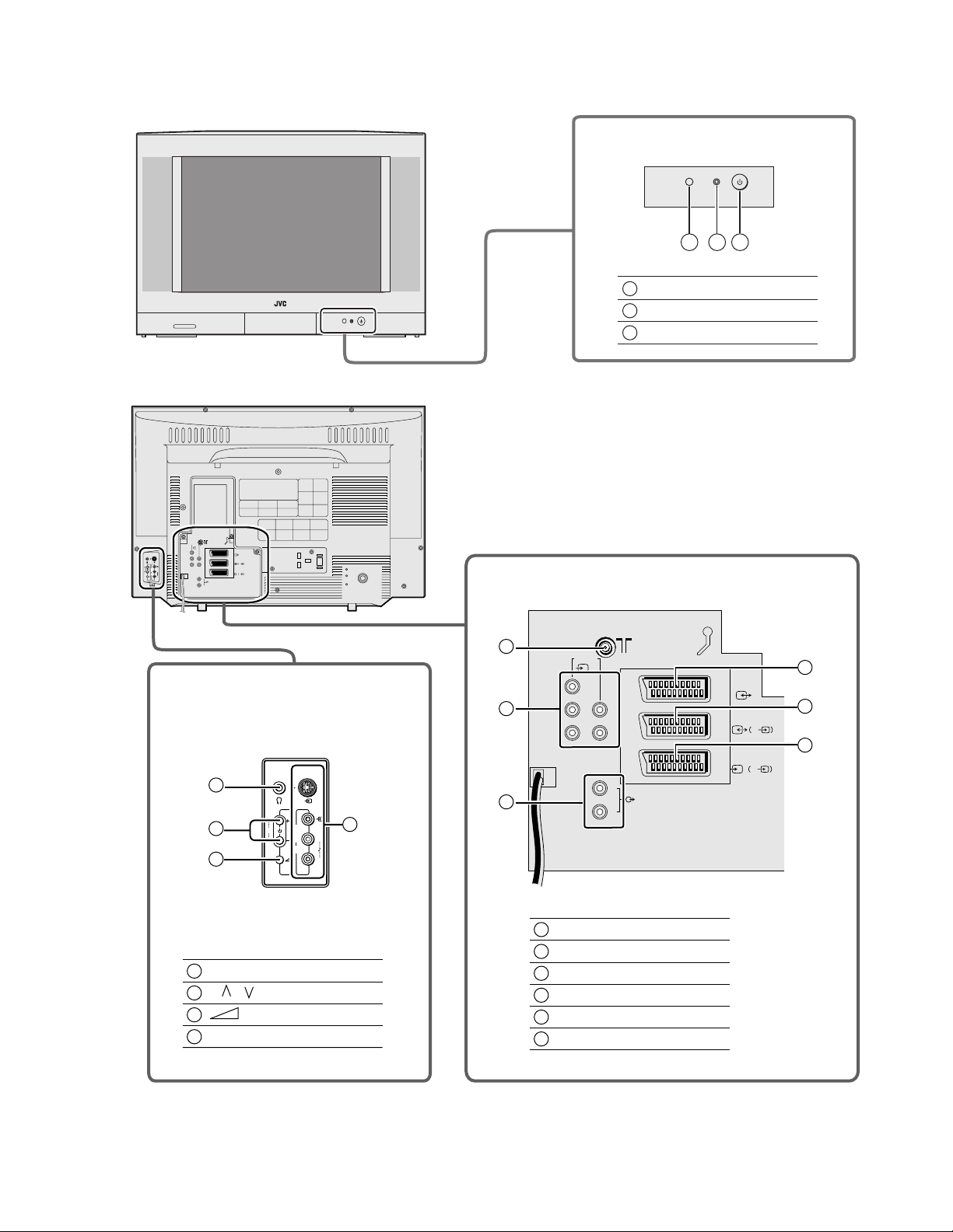
2.4 FUNCTIONS
FRONT PANEL
REAR PANEL
1 2 3
Remote control sensor
1
Power lamp
2
3
Power button
EXT-
4
EXT-
1
Y
L
EXT-
S
E
P
X
L
T
5
R
2
S
PrPbR
EXT-
3
S
L
AUDIO OUT
R
SIDE CONTROL JACK
AV TERMINAL BOARD
8
9
EXT-
Y
PrPbR
4
EXT-1
L
EXT-2
11
12
S
13
EXT-3
S
4
S
5
6
4
Headphone jack
5
P / buttons, -/+ buttons
6
Volume button
EXT-5 terminal
7
E
P
X
T
5
10
7
L
R
8
Aeriel terminal
9
EXT-4 terminal
10
AUDIO OUT terminal
11
EXT-1 terminal
12
EXT-2 terminal
13
EXT-3 terminal
L
R
AUDIO OUT
(No.YA010)1-7
Page 8
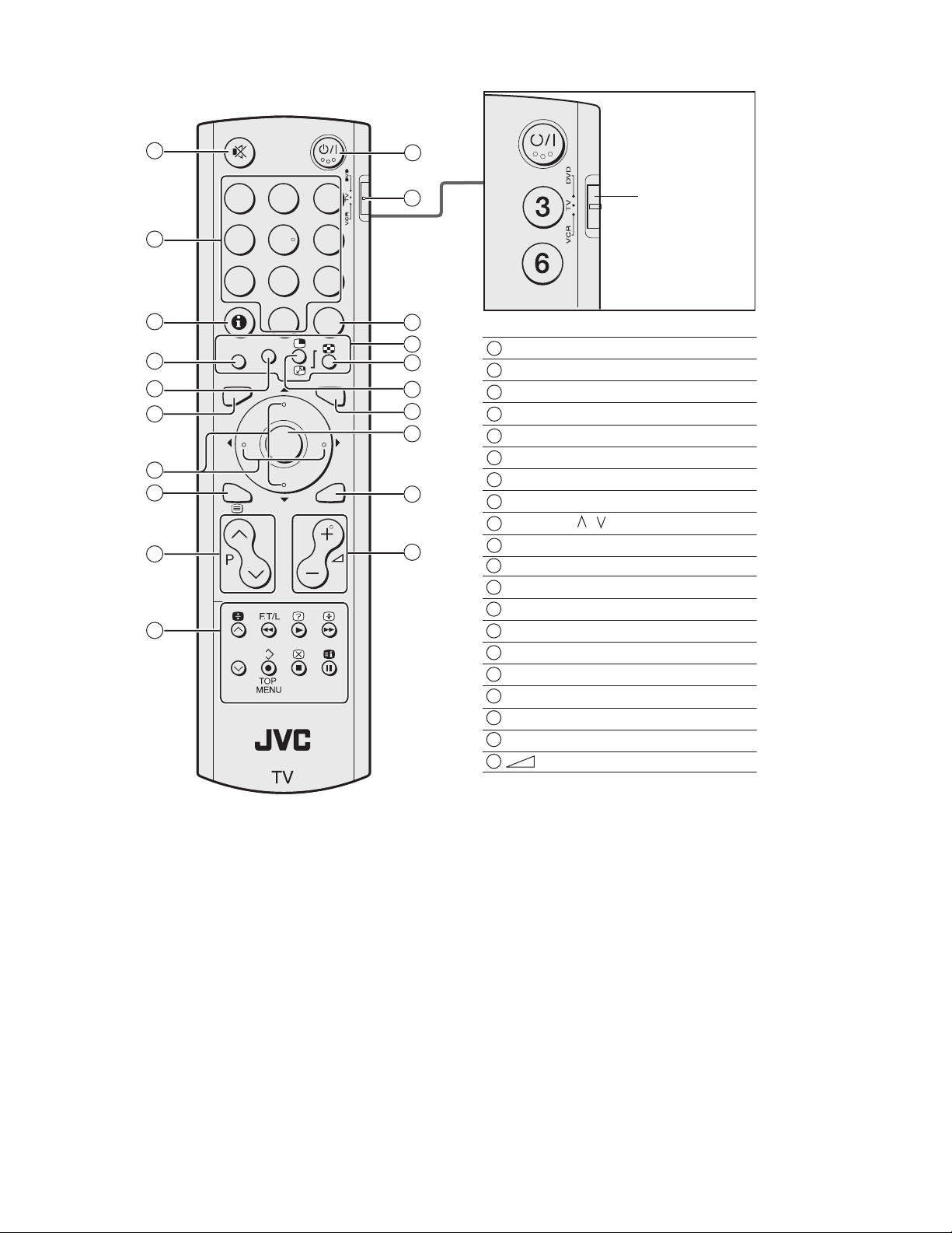
REMOTE CONTROL UNIT
1
2
3
4
5
6
7
8
9
10
123
4
56
9
8
7
0
AV
3D
ZOOM
TV
MENU
OK
BACK
11
12
13
14
15
16
17
18
19
20
VCR / TV / DVD
switch
1
Muting key
2
Number key
3
Information key
Zoom key
4
3D Sound key
5
TV key
6
Function (UP/DOWN, RIGHT/LEFT) keys
7
Text key
8
Programme / keys
9
VCR/DVD/Text control key
10
11
Standby key
12
VCR/TV/DVD Switch
13
AV key
14
Colour key
15
Multi screen key
16
Freeze/Swap key
17
MENU key
18
OK key
19
BACK key
20
Volume -/+ keys
1-8 (No.YA010)
Page 9
2.5 TECHNICAL INFORMATION
2.5.1 SYSTEM BLOCK DIAGRAM
MAIN PWB
IC1781[10]
MAIN MEMORY
SCL0 / SDA0
DIST PWB
IC1301[0Z]
RGB PROCESSOR
MAIN PWB
IC1721[10]
IP LATCH
IC3001[0Z]
MAIN CHROMA
DEMODULATOR
IC1701[10]
MAIN DAC
IC0212[0H]
DAC1
SCL1 / SDA1
IC801[0S]
SUB CHROMA
DEMODULATOR
IC001[0M]
MAIN MICRO COMPUTER
DEF OSC PWB
IC0161[0H]
DEF CONTROL
IC802[0S]
SUB DIGITAL
COMB FILTER
AV SW PWB
MAIN PWB
TU1001[10]
SCL3 / SDA3
TUNER
IC101[0S]
AV S W
AV SW PWB
IC1251[10]
COMPONENT VIDEO
SW
IC1201[10]
SYNC SEP
IC1001[0Z]
DIST PROCESSOR
DIST PWB
IC1101[10]
MULTI SOUND
PROCESSOR
SCL2 / SDA2
(No.YA010)1-9
Page 10
SECTION 3
DISASSEMBLY
3.1 DISASSEMBLY PROCEDURE
3.1.1 REMOVING THE REAR COVER
(1) Unplug the power plug.
(2) Remove 13 screws [A] as shown in the Fig. 3.
(3) Withdraw the REAR COVER toward you.
NOTE:
When reinstalling the rear cover, carefully push it i nward after
inserting the chassis into the rear cover groove.
3.1.2 REMOVING THE SIDE CONTROL JACK ASSY
• Remove the REAR COVER.
(1) Remove 1 screw [B] as shown in Fig.3.
(2) Slightly pull the SIDE CONTROL JACK ASSY toward you,
and detach the claw from FRONT CABINET. Then it can be
removed.
(3) Then disconnect the conne ctor [F] and [CN 016] as shown
in Fig.1.
3.1.3 REMOVING THE SIDE CONTROL PWB
• Remove the REAR COVER.
• Remove the SIDE CONTROL JACK ASSY.
(1) Remove 3 claws [C] from backside of the SIDE CONTROL
JACK ASSY as shown in Fig.1.
(2) Remove the SIDE CONTROL PWB from the SIDE
CONTROL JACK ASSY.
3.1.7 CHECKING THE PW BOARD
(1) Pull out the MAIN CHASSIS (Refer to REMOVING THE
MAIN CHASSIS).
(2) Erect the MAIN CHASSIS vertically so that you can easily
check the PW Board from back side.
3.1.8 CAUTION
(1) When erecting the MAIN CHASSIS, be careful so that
there will be no contacting with other PW Board.
(2) Before turning on power, make sure that the wire connector
is properly connected.
(3) When conducting a check with power supplied , be sure to
confirm that the CRT EARTH WIRE (BRAIDED ASS'Y) is
connected to the CRT SOCKET PW board.
3.1.9 WIRE CLAMPING AND CABLE TYING
(1) Be sure to clamp the wire.
(2) Never remove the cable tie used for tying the wires
together.
Should it be inadvertently removed, be sure to tie the wires
with a new cable tie.
3.1.4 REMOVING THE AV TERMINAL BOARD
• Remove the REAR COVER.
(1) Remove 7 screws [D] as shown in Fig.3.
(2) Remove 2 claws [E] at the bottom of the AV TERMINAL
BOARD as shown in Fig.2.
(3) Shift the AV TERMINAL BOARD slightly in the direction of
arrow [G], and remove it as shown in Fig.2.
3.1.5 REMOVING THE MAIN CHASSIS
• Remove the REAR COVER.
(1) Slightly raise the MAIN CHASSIS, and release two claws
at the bottom of both sides of the MAIN CHASSIS.
(2) Then withdraw the MAIN CHASSIS backward from the
FRONT CABINET (If necessary, detach the wire clamp,
connectors etc.).
3.1.6 REMOVING THE MAIN SPEAKER
• Remove the REAR COVER.
(1) Remove 2 screws [H], and detach the MAIN SPEAKER
HOLDER as shown in Fig.3 (When removing 2 screws [H]
of the MAIN SPEAKER HOLDER, the lower side screw
first, and then upper one).
(2) Remove 2 screws [J] attached the MAIN SPEAKER.
(3) Follow the same steps when disassemble the other hand
MAIN SPEAKER.
F
CN016
AV TERMINAL
BOARD
C
SIDE CONTROL
PWB
C
(Back view)
Fig.1
G
E
E
1-10 (No.YA010)
Fig.2
Page 11
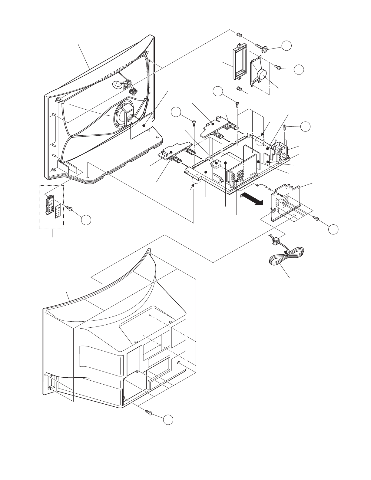
FRONT CABINET
CRT SOCKET
PWB
LINE FILTER PWB
K
MI-COM
PWB
MAIN SPEAKER
HOLDER
L
LF BASE
MAIN SPEAKER
CLAW
H
J
POWER & DEF. PWB
M
HVT HOLDER
MAIN CHASSIS
Fig.1
REAR COVER
FRONT
CONTROL
PWB
CONTROL
BASE
B
CLAW
MAIN PWB
DIST PWB
AV SW PWB
EHT PWB
DEF OSC PWB
AV TERMINAL
BOARD
D
POWER CORD
A
Fig.3
(No.YA010)1-11
Page 12
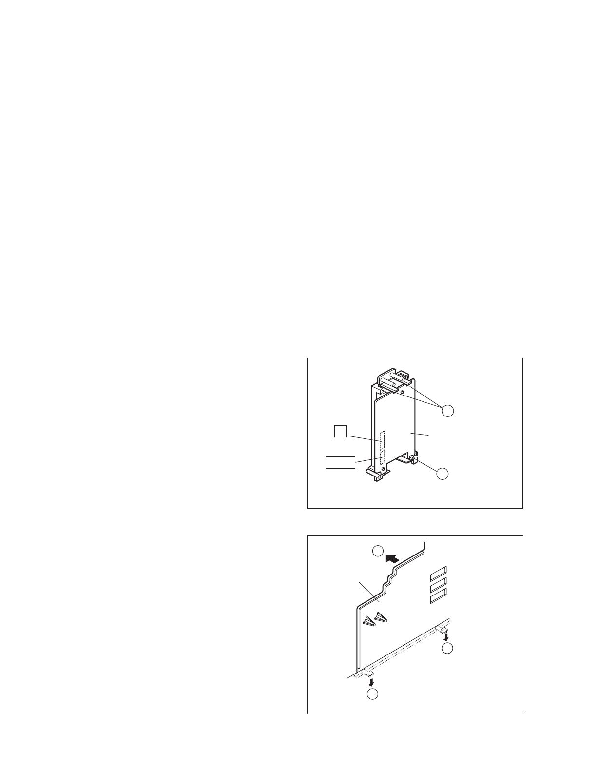
3.2 MEMORY IC REPLACEMENT
3.2.1 MEMORY IC
This TV use the memory IC. In the memory IC, there are memorized data for correctly operating for the video and deflection circuits
and more. When replacing the memory IC, be sure to use IC written with the initial values of data.
3.2.2 PROCEDURE FOR REPLACING MEMORY IC
1. Power off
Turn the power off and unplug the power plug.
2. Replace IC.
Be sure to use the memory IC written with the initial se tting
data.
SERVICE MENU
1. IF
3. AUDIO
5. VSM PRESET
7. 3DNR
9. SHIPPING(OFF)
1-9 : SELECT i : EXIT
2. V/C
4. DEF
6. STATUS
8. IP
0. BUS FREE
3. Power on
Connect the power plug and turn the power on.
4. Setting of recieve channels
Fig.1
Set the receive channels. For setting, refer to the OPERATING
INSTRUCTIONS.
5. User settings
SYSTEM CONSTANT SET
1. P MUTE NO
Check the user setting items according to "FACTORY
SHIPPING" at page later. If these are different, set the correct
value.
6. Check the SYSTEM CONSTANT items
(1) Before operating the SERVICE MENU, con firm that the
setting of VCR/TV/DVD switch of the REMOTE
CONTROL UNIT is at the "TV" side. If this switch have
not been properly set, you cannot enter the SERVICE
MENU.
(2) Press the [INFORMATION ] key and [MUTING] key on
the REMOTE CONTROL UNIT simultaneously.
(3) The SERVICE MENU screen on Fig.1 will be displayed.
(4) While the SERVICE MENU is displayed, again press the
[INFORMATION] key and [MUTING] key simultaneously.
Then display the SYSTEM CONSTANAT SET screen as
shown in Fig.2.
(5) Refer to the "SETTING VALUE OF SYSTEM
CONSTANT SET", and check the setting items. when it
differ, adjust it with the [FUNCTION (UP/DOWN)] key
and adjust it with the [FUNCTION (RIGHT/LEFT)] keys.
(6) Press the [MENU] key to memorize the setting value.
(7) Press the [INFORMATION] key twice to return to the
normal screen.
7.SERVICE MENU setting
Verify what to set in the SERVICE MENU, and set whatever is
necessary. Refer to the ADJUSTMENT for setting.
MUTING
SERVICE MENU
Enter
INFORMATION
Exit SERVICE MENU
FUNCTION
UP / DOWN
Select the setting item
- / + : STORE i : EXIT
MENU
Fig.2
123
4756
9
8
0
AV
3D
ZOOM
TV
MENU
OK
BACK
VCR/TV/DVD
SWITCH
MENU
Memorize the
adjustment data
FUNCTION
RIGHT/LEFT
Adjust the value
1-12 (No.YA010)
Page 13
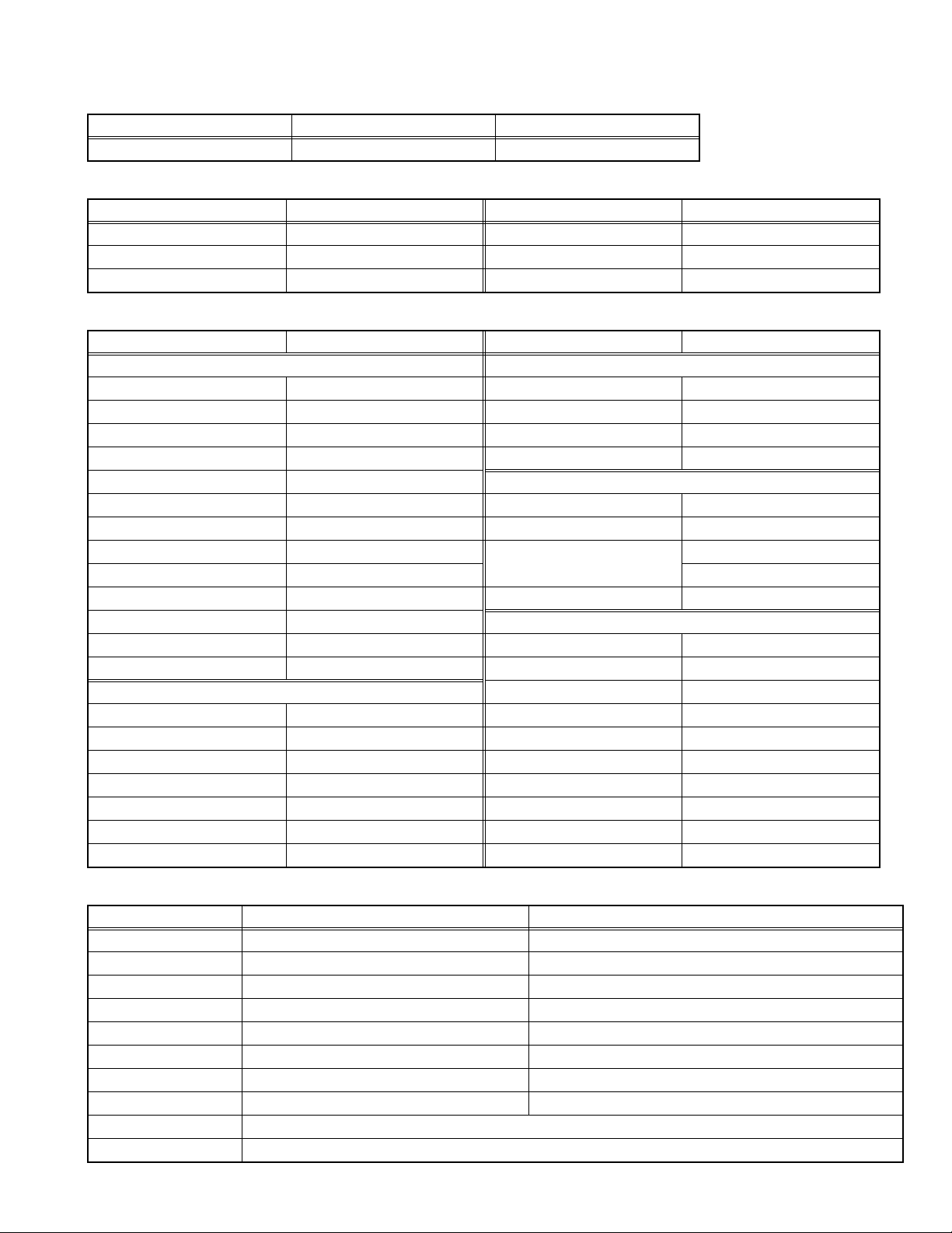
3.3 FACTORY SHIPPING SETTING
3.3.1 SETTING VALUE OF SYSTEM CONSTANT SET
Setting item Variable range Setting value
1. P MUTE YES / NO NO
3.3.2 SETTING OF REMOTE CONTROL UNIT
Setting item Setting value Setting item Setting value
POWER ON 3D SOUND OFF
VOLUME 10 ZOOM PANORAMIC
CHANNEL 1 MULTI SCREEN OFF
3.3.3 SETTING OF MENU SCREEN
Setting item Setting value Setting item Setting value
PICTURE SETTING FEATURES
PICTURE MODE BRIGHT SLEEP TIMER OFF
CONTRAST Centre BLUE BACK ON
BRIGHT Centre CHILD LOCK ID:-----, ALL CH OFF
SHARP Centre APPEARANCE TYPE A
COLOUR Centre SETUP
HUE Centre LANGUAGE ENGLISH
COLOR TEMP. COOL PICTURE TILT Centre
DIGITAL VNR AUTO(LOW) EDIT / MANUAL PRESET CH only
Super Digipure AUTO others : Blank
MOVIE THEATER AUTO DECORDER(EXT-2) OFF
Colour Digipure ON EXT SETTING
COLOR SYSTEM Depend on preset channel S-IN EXT-2
4:3 AUTO ASPECT PANORAMIC ID LIST Blank
SOUND SETTING DUBBING EXT-2
BASS Centre
TREBLE Centre
BALANCE Centre
HEADPHONE VOLUME 10
3D CINEMA SOUND ON
SURROUND MID
BASS BOOST MID
3.3.4 SERVICE MENU SETTING ITEMS
Service menu Sub menu item Description
1. IF 1. VCO, 2. ATT
2. V/C 1. CUT_OF_R ~ 15. RY_ANGLE
3. AUDIO 1. ERROR LIMIT ~ 21. CENT TRE It is no required for adjustment. Don't change the value.
4. DEF 1. FREE-RUN ~ 11. V. LIN
5. VSM PRESET 1. CONT ~ 8. WDR B
6. STATUS 1. SOFT ~ 4. IC It is no required for adjustment. Don't change the value.
7. 3DNR 1. YNR LIM ~ 90. HGCON21 It is no required for adjustment. Don't change the value.
8. IP 1. ASL GAIN ~ 70. BVMCORINGON It is no required for adjustment. Don't change the value .
9. SHIPPING Initialize the all data. It is no requirement for adjustment.
2
0. BUS FREE Stops the all I
C bus communication. It is no requirement for adjustment.
(No.YA010)1-13
Page 14

3.4 REPLACEMENT OF CHIP COMPONENT
3.4.1 CAUTIONS
(1) Avoid heating for more than 3 seconds.
(2) Do not rub the electrodes and the resist parts of the pattern.
(3) When removing a chip part, melt the solder adequately.
(4) Do not reuse a chip part after removing it.
3.4.2 SOLDERING IRON
(1) Use a high insulation soldering iron with a thin pointed end of it.
(2) A 30w soldering iron is recommended for ea sily removing parts.
3.4.3 REPLACEMENT STEPS
1. How to remove Chip parts
2. How to install Chip parts
[Resistors, capacitors, etc.]
(1) As shown in the figure, push the part with tweezers and al-
ternately melt the solder at each end.
(2) Shift with the tweezers and remove the chip part.
[Transistors, diodes, variable resistors, etc.]
(1) Apply extra solder to each lead.
SOLDER
SOLDER
[Resistors, capacitors, etc.]
(1) Apply solder to the pattern as indicated in the figure.
(2) Grasp the chip part with tweezers and place it on the sol-
der. Then heat and melt the solder at both ends of the chip
part.
[Transistors, diodes, variable resistors, etc.]
(1) Apply solder to the pattern as indicated in the figure.
(2) Grasp the chip part with tweezers and place it on the sol-
der.
(3) First solder lead A as indicated in the figure.
(2) As shown in the figure, push the part with tweezers and al-
ternately melt the solder at each lead. Shift and remove the
chip part.
NOTE :
After removing the part, remove remaining solder from the pattern.
1-14 (No.YA010)
A
B
C
(4) Then solder leads B and C.
A
B
C
Page 15

SECTION 4
ADJUSTMENT
4.1 ADJUSTMENT PREPARATION
(1) There are 2 ways of adjusting this TV : One is with the REMOTE CONTROL UNIT an d the other is the conventional method
using adjustment parts and components.
(2) The adjustment using the REMOTE CONTROL UNIT is made on the basis of the initial setting values. The setting values which
adjust the screen to the optimum condition can be different from the initial setting values.
(3) Make sure that connection is correctly made AC to AC power source.
(4) Turn on the power of the TV and measuring instruments for warning up for at least 30 minutes before starting adjustme nts.
(5) If the receive or input signal is not specified, use the most appropriate signal for adjustment.
(6) Never touch the parts (such as variable resistors, transformers and condensers) not shown in the adjustment items of this service
adjustment.
(7) Preparation for adjustment. Unless otherwise specified in the adjustment items, preset the following functions with the REMOTE
CONTROL UNIT.
Item Preset value Item Preset value
PICTURE MODE STANDARD Super Digipure ON
CONTRAST Centre MOVIE THEATER AUTO
BRIGHT Centre BASS / TREBLE / BALANCE Centre
SHARP Centre 3D CINEMA SOUND OFF
COLOUR Centre ZOOM FULL
HUE Centre SLEEP TIMER OFF
COLOUR TEMP COOL BLUE BACK OFF
DIGITAL VNR AUTO(LOW)
Colour Digipure AUTO
4.2 MESURING INSTRUMENT AND FIXTURES
(1) DC voltmeter (or digital voltmeter)
(2) HV voltmeter
(3) Oscilloscope
(4) Signal generator (Pattern generator : PAL, SECAM, NTSC)
(5) Remote control unit
4.3 ADJUSTMENT ITEM
B1 POWER SUPPLY check
HIGH VOLTAGE
HORIZONTAL FREQUENCY
FOCUS
IF VCO check
FOCUS ADJUSTMENT
VSM PRESET
VIDEO CIRCUIT
WHITE BALANCE (LOW LIGHT)
WHITE BALANCE (HIGH LIGHT)
SUB BRIGHT
SUB CONTRAST
SUB COLOR
SUB TINT
DEFLECTION CIRCUIT
V SHIFT
V SIZE
H POSITION
H SIZE
SIDE PINC
TRAPEZIUM
CORNER PIN
V LINEARITY
SUB SCREEN
CONTRAST
COLOUR
TINT
(No.YA010)1-15
Page 16

4.4 ADJUSTMENT LOCATIONS
FRONT CONTROL PWB
F901
POWER SW
POWER CORD
PW
TO LINE FILTER PWB
TOP
SIDE CONTROL PWB
HEAD
PHONE
UP
TO AV SW PWB
J004
F
W
FRONT
B
TO MAIN PWB
MAIN PWB
SR
SL RT
TO SPEAKER
TUNER
TO DEG COIL
FRONT
TO SIDE CONTROL PWB
TO FRONT CONTROL PWB
MI-COM PWB
DIST PWB
CN008
POWER & DEF. PWB
B
CN016
CN001
CN002
CN001
CN002
J
DEF OSC PWB
P
DOWN
MENU
CN016
TO MAIN PWB
AV SW PWB
J004
J005
J006
TOP
J001
J002
J003
CN009
AV SW PWB
CN003
CN003
CN010
CN007CN006
CN007CN006
C
F
TO SIDE
CONTROL PWB
HV
A
1-16 (No.YA010)
Page 17

FRONT
LINE FILTER PWB
MI-COM PWB
DIST PWB
CN008
CN009
MAIN PWB
B
CN016
CN001
CN002
CN003
POWER & DEF. PWB
TO LINE FILTER PWB
CN001
CN002
J
DEF OSC PWB
CN003
P
TO CRT SOCKET PWB
TO DEF YOKE
CN010
FRONT
TO LINE FILTER PWB
HV
TO FRONT CONTROL PWB
X
EHT PWB
CN011
DEG
1: TP-E
2: NC
3: X-RAY1
4: NC
5: TP-91
W
TO POWER & DEF. PWB
TO DEG COIL
FBT
X
EHT PWB
X-RAY ADJ
P
TO POWER & DEF. PWB
TOP
R2533
R2528
EHT ADJ
CN011
CN007
TOP
C
AV SW PWB
CRT SOCKET PWB
VM
TO POWER & DEF. PWB
TO CRT SOCKET PWB
TP-47R
R3225 Lead
(IC3202 9Pin side)
TP-E
TP-47G
R3224 Lead
(IC3201 9Pin side)
A
TO IP PWB
A
EJ
S1
1
5
FOCUS2
FOCUS1
SCREEN
(No.YA010)1-17
Page 18

4.5 TOOL OF SERVICE MENU OPERATION
Operate the SERVICE MENU with the REMOTE CONTROL UNIT.
4.5.1 SERVICE MENU ITEMS
With the SERVICE MENU, various adjustment can be made, and they are broadly classified in the following items of settings.
Sub Menu item Description
1.IF This mode adjusts the IF circuit.
2.V/C This mode adjusts the VIDEO circuit
3.AUDIO This mode adjusts the AUDIO circuit. [It is no requirement for adjustment.]
4.DEF This mode adjusts the DEFLECTION circuit.
5.VSM PRESET This mode sets the VSM (Video Status Memory) data.
2
6.STATUS This mode shows the I
C memory data software version and information.
[It is no requirement for adjustment.]
7.3DNR This mode adjusts the 3D NR (three-Dimension Noise Reduction) circuit.
[It is no requirement for adjustment.]
8.IP This mode adjusts the DIST circuit. [It is no requirement for adjustment.]
9.SHIPPING This mode initialize the data for factory shipment.
Not to select this mode during adjusting. [It is no requirement for adjustment.]
2
0.BUS FREE This mode stops the all I
C bus communication.
Not to select this mode during adjusting. [It is no requirement for adjustment.]
4.5.2 BASIC OPERATION IN SERVICE MENU
4.5.2.1 HOW TO ENTER THE SERVICE MENU
Before operating SERVICE MENU, confirm that the setting of
VCR/TV/DVD switch of the REMOTE CONTROL UNIT is at the
"TV" side. If this switch have not been properly set, you cannot
enter the SERVICE MENU.
Press the [INFORMATION] key and [MUTING] key of the
REMOTE CONTROL UNIT simultaneously. Then SERVICE
MENU screen will be displayed as shown figure.
4.5.3 SUB MENU SCREEN SELECTION
Press one of the CHANNEL number key with the remote control
unit, and select the SUB MENU SCREEN from SERVICE MENU.
4.5.4 MEMORIZE THE ADJUSTMENT DATA
When adjustment is completed, press the [MENU] key to
memorize the adjustment value. If not to do it, adjustment data is
not memorized to the memory IC. And if exit the adjustment
mode before memorize the data, the adjustment value which you
change is canceled.
4.5.5 RELEASE OF SERVICE MENU
When adjustment is completed, press the [INFORMATION] key.
Then return to the SERVICE MENU screen.
Again press the [INFORMATION] key, you can return to the
normal screen.
1. IF
3. AUDIO
5. VSM PRESET
7. 3DNR
9. SHIPPING(OFF)
MUTING
SERVICE MENU
Enter
INFORMATION
Exit SERVICE MENU
SERVICE MENU
2. V/C
4. DEF
6. STATUS
8. IP
0. BUS FREE
1-9 : SELECT i : EXIT
123
4756
8
0
AV
3D
ZOOM
VCR/TV/DVD
SWITCH
9
1-18 (No.YA010)
FUNCTION
UP / DOWN
Select the setting item
TV
MENU
OK
BACK
MENU
Memorize the
adjustment data
FUNCTION
RIGHT/LEFT
Adjust the value
Page 19

4.5.6 DESCRIPTION OF SERVICE MENU SCREEN
Describe the screen when display the sub menu screen. For example, describe about 2. V/C, 4. DEF and 5. VSM PRESET.
4.5.6.1 2. V/C
4.5.6.3 5. VSM PRESET
Setting item
Colour System
PAL
SECAM
N3
N4
4.5.6.2 4. DEF
DEF FULL 1125I
V / C N3
1.CUT_OF_R 130
- / + : STORE i : EXIT
MENU
Colour system
Setting value
****************
: PAL
: SECAM
: NTSC3.58
: NTSC4.43
Input signal
1. FREE-RUN 0
Setting item
- / + : STORE i : EXIT
Zoom mode
( 93)
Setting value
MENU
VSM PRESET BRIGHT
1. CONT 16
Setting item Setting value
- / + : STORE i : EXIT
MENU
VSM mode
VSM mode
BRIGHT
STD
SOFT
COOL
NORMAL
WARM
: BRIGHT
: STANDARD
: SOFT
: COOL
: NORMAL
: WARM
Zoom mode
FULL : FUL L
Display only FULL mode. Adjustment in other
zoom modes are not required.
Input signal
900i
: 900i
1125i
: 1125i
1350i
: 1350i
602p
: 602p
(No.YA010)1-19
Page 20

4.5.7 SETTING METHOD OF SUB MENU SCREEN
4.5.7.1 1. IF [Perform only confirmation]
When enter to the 1. IF adjustment screen, display the sub select
screen as shown in figure. Then select the one of 1.VCO or 2.
ATT with CHANNEL number key on the remote control unit.
1. VCO screen
1) VCO condition
Display the VCO condition. The letter where yellow arrow points
is current VCO condition.
2) Exit
Press the [INFORMATION] key twice to exit to the service menu.
4.5.7.2 2. V/C, 4. DEF and 5. VSM PRESET
The operation method in each screen is almost the same.
1) Setting item
Press the [FUNCTION (UP/DWON)] key to select the setting
item.
2) Setting value
Press the FUNCTION (RIGHT/LEFT)] key to adjust the value.
3) Memorize
Press the [MENU] key to memorize the adjustment value.
4) Exit
Press the [INFORMATION] key twice to exit to the service menu.
2. V/C
IF SERVICE MENU
1. VCO
2. ATT ON / OFF
1-2:SELECT i : EXIT
VCO(CW) **.**MHz
MAIN
TOO HIGH
ABOVE REF.
JUST REF.
BELOW REF.
TOO LOW
VCO condition
1.CUT_OF_R 130
Setting item
1.CUT_OF_R~15.RY ANGL
- / + : STORE i : EXIT
****************
Memorize the value
Yellow arrow
i : EXIT
Exit key
V / C N3
Setting value
MENU
Exit from this mode
4. DEF
DEF FULL 1125i
1. FREE-RUN 0
Select the setting item
1.FREE-RUN~11.V-LIN
5. VSM PRESET
VSM PRESET BRIGHT
1. CONT 16
Setting item
CONT~WDR B
Memorize the value
4.5.7.3 3. AUDIO, 6. STATUS, 7. 3DNR, 8. IP, 9. SHIPPING and 0. BUS FREE
It is no requirement for adjustment. Do not change the values in these sub menu screen.
- / + : STORE i : EXIT
MENU
Exit from this modeMemorize the value
Setting value
- / + : STORE i : EXIT
MENU
Exit from this mode
( 93)
Setting value
1-20 (No.YA010)
Page 21

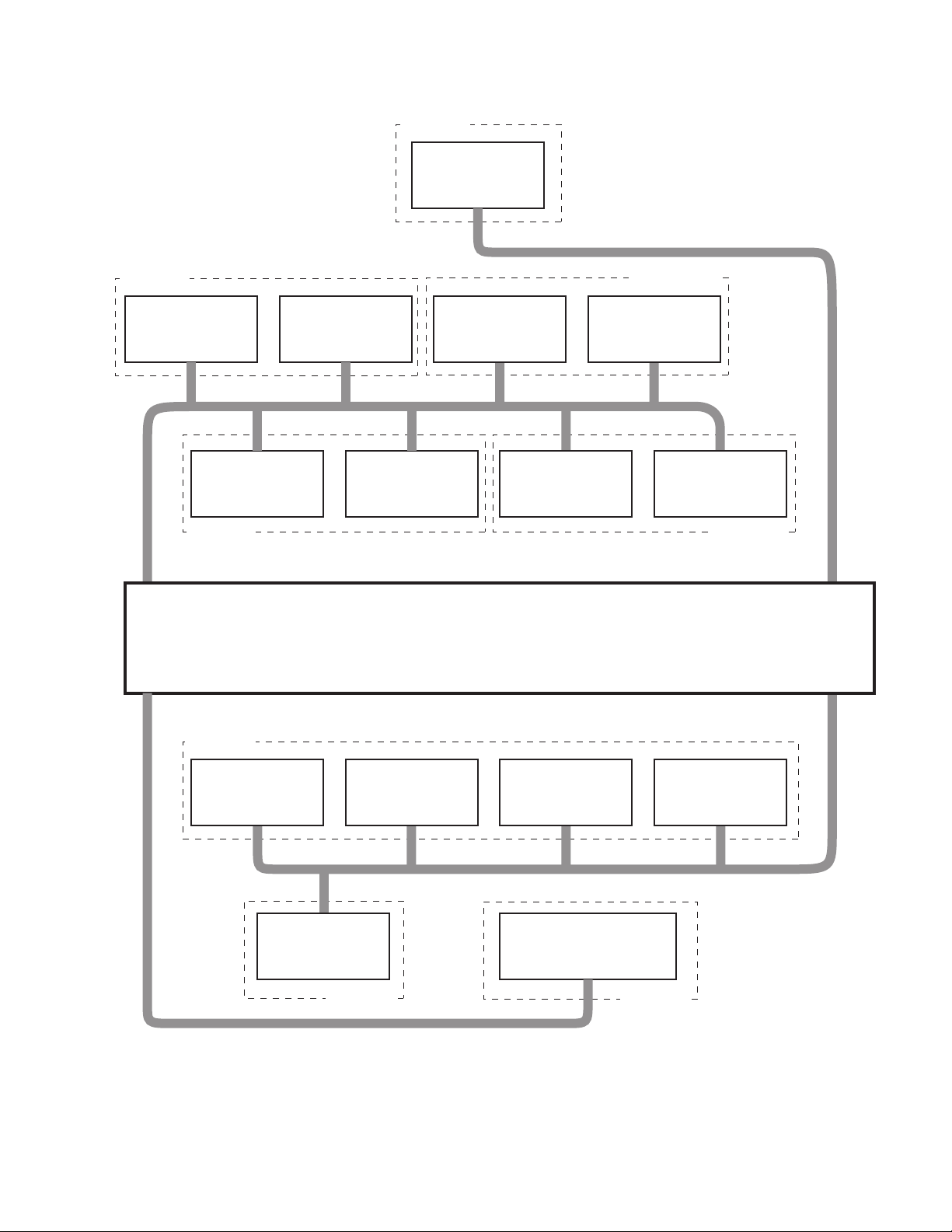
4.6 SERVICE MENU FLOW CHART
SERVICE MENU
SERVICE MENU
1. IF
3. AUDIO
5. VSM PRESET
7. 3DNR
9. SHIPPING(OFF)
1-9 : SELECT i : EXIT
2. V/C
4. DEF
6. STATUS
8. IP
0. BUS FREE
1.IF
IF SERVICE MENU
1. VCO
2. ATT ON / OFF
1-2: SELECT i : EXIT
2. V/C
V /C N3
1.CUT_OF_R 130
- / + : STORE i : EXIT
MENU
################
3. AUDIO
AUDIO
1. ERROR LIMIT 0100
ERROR LIMIT = D7FF
C_AD_BITS = 00000000
Do not adjust.
6. STATUS
STATUS
1. SOFT
- / + : STORE i : EXIT
MENU
7. 3DNR
3DNR 3DYC
1. YNR LIM 0000
- / + : STORE i : EXIT
MENU
8. IP
IP 900i
1. ASLGAIN 0000
- / + : STORE i : EXIT
MENU
Do not adjust.
Do not adjust.
Do not adjust.
- / + : STORE i : EXIT
MENU
4. DEF
DEF FULL 1125i
1. FREE-RUN 0
- / + : STORE i : EXIT
MENU
(93)
5. VSM PRESET
VSM PRESET BRIGHT
1. CONT 16
- / + : STORE i : EXIT
MENU
9. SHIPPING
SHIPPING (OFF)
SHIPPING (ON)
0. BUS FREE
I2C BUS FREE
Do not adjust.
Do not adjust.
(No.YA010)1-21
Page 22

4.7 INITIAL SETTING VALUE OF SERVICE MENU
(1) Adjustment of the SERVICE MENU is made on the basi s of the initial setting values. Ho wever, the new setting values which
displays on the screen in its optimum condition may differ from the initial setting value.
(2) Do not change the initial setting values of the items not li sted in "ADJUSTMENT PROCEDURE".
(3) "---" is impossible to adjust or not requirement to adjustment.
4.7.1 [1. IF]
Setting item Variable range Initial setting value
2.ATT ON/OFF OFF
4.7.2 [2. V/C]
Initial setting value
Setting item
Variable
range
RF External (Composite / S) External (Component)
SECAM PAL SECAM
PAL
NTSC
3.58
NTSC
4.43
625i 525i 625p 525p 1125i 1125i
1.CUT_OF R 000~255 130 130 0 0
2.CUT_OF G 000~255 130 130 0 0
3.CUT_OF B 000~255 130 130 0 0
4.DRIVE_R 000~255 64 64 0 0
5.DRIVE_G 000~255 64 64 0 0
6.DRIVE_B 000~255 64 64 0 0
7.BRIGHT 000~255 130 130 0 0
8.CONT 000~127 52 52 0 0
9.COLOR 000~127 80 55 0 0 63 0 0 0 0 0 0 0
10.HUE 000~127000063068680000
11.TWN_CNT 000~015 9 0 0 0 0 0 0
12.TWN_COL000~015990090000000
13.TWN_TNT000~0000000350000000
14.BY_GAIN 000~063 43 43 43 0 0 0 0 0 0 0
15.RY_ANGL 000~015 7 7 7 0 0 0 0 0 0 0
4.7.3 [5. VSM PRESET]
Initial setting value
Setting item
Variable
range
PICTURE MODE COLOUR TEMP
BRIGHT STANDARD SOFT COOL NORMAL WARM
CONT -16~16 +16 +2 -8 ----- ----- ----BRIGHT -16~16 0 0 0 ----- ----- ----SHARP -16~16 0 0 -2 ----- ----- ----COLOUR -16~16 0 0 -2 ----- ----- ----TINT -16~16 0 0 0 ----- ----- ----WDR R -64~63 ----- ----- ----- -6 0 +11
WDR G -64~63 ----- ----- ----- 0 0 0
WDR B -64~63 ----- ----- ----- +12 0 0
1-22 (No.YA010)
Page 23

4.7.4 [3. AUDIO]
Setting item Variable range Initial setting value
1.ERROR LIMIT 0000H~FFF0H 100H
2.A2 ID THR 0000H~00FFH 19H
3.Q-PEAK B/G→I→D/K→L -----
4.SOUND LEVEL ----- FFFFH
Initial setting value
Setting item Variable range
LOW MID HIGH
5.VIRT_MODE PANORAMA /
3D PANORAMA
6.VIRT_SPAT 0000H~007FH 0FH 28H 32H
7.VIRTUAL EF 0000H~007FH 0CH 23H 2FH
Setting item Variable range Initial setting value
8.SPATIAL EF 0000H~00FFH 3FH
Setting item Variable range
9.MB STR 0000H~007FH 00H 00H 25H 32H 39H
10.MB HMC 0000H~007FH 00H 00H 00H 00H 00H
11.MB HP 0000H~001EH 00H 00H 08H 00H 00H
12.MB LP 0000H~001EH 00H 00H 14H 12H 10H
13.MB LIMIT 00E0H~0000H 00H 00H 00H F6 H F1H
14.SUBW LEVEL 0080H~000CH 00H 00H 00H 00H 00H
15.SUBW FREQ 0000H~0028H 00H 00H 1CH 00H 00H
16.SUBW CHAR 0000H~0003H 00H 00H 01H 00H 00H
17.SUBW HP 0000H~0002H 00H 00H 02H 00H 00H
18.VOL CLP M 0000H~0003H 03H 03H 00H 00H 00H
3D PANORAMA 3D PANORAMA 3D PANORAMA
OFF MONO LOW MID HIGH
SURROUND
Initial setting value
BASS BOOST
Setting item Variable range Initial setting value
19.A PROTECT 0000H~0100H 100H
20.CENT BASS 00F1H~000FH 0H
21.CENT TRE 00F1H~000FH 0H
4.7.5 [4. DEF]
Setting item Variab le range
1.FREE-RUN 0~225 90 0 0 0
2.V-SHIFT 0~63 23 0 0 0
3.V-SIZE 0~127 43 0 0 -3
4.H-CENT 255~0 47 0 0 0
5.H-SIZE 0~63 32 0 0 0
6.TRAPEZ 0~63 33 0 0 0
7.EW-PIN 0~63 25 0 0 0
8.COR-UP 0~158000
9.COR-LOW0~158000
10.V.S-COR 0~63 24 0 0 0
11.V-LIN 0~63 41 0 3 0
900i 1125i 1350i 602p
Initial setting value
(No.YA010)1-23
Page 24

4.7.6 [7.3DNR]
Initial setting value
Setting item Variable range
PAL SECAM
1. YNR LIM 0000~0003 03
2. YNR K 0000~0003 02
3. YNR GAIN 0000~0003 00
4. CNR LIM 0000~0003 03
5. CNR K 0000~0003 02
6. CNR GAIN 0000~0003 01
7. LTI GAIN 0000~0003 00010000000100000000
8. LTI SLICE 0000~0003 00000000000000000000
9. CTI GAIN 0000~0003 02030302020303020202
10. CTI SLICE 0000~0003 00000000000000000000
11. BRIGHTNESS 0000~000F 01 01 01
12. CONTRAST 0000~00FF 24 24 30
13. AC M SLP 0000~0003 03030103030301030303
14. AC S SLP 0000~0003 03030203030302030303
15. AY M SLP 0000~0003 02020202020202020202
16. AY S SLP 0000~0003 02020202020202020202
17. AC M E SET0000~0003 02020302020203020202
18. AC M F SET0000~0003 02020302020203020202
19. AC S E SET0000~0003 00000200000002000000
20. AC S F SET 0000~0003 00000200000002000000
21. AY M E SET0000~0003 02020302020203020202
22. AY M F SET0000~0003 02020302020203020202
23. AY S E SET0000~0003 00000100000001000000
24. AY S F SET 0000~0003 00000100000001000000
25. BC M SLP 0000~0003 03030303030303030303
26. BC S SLP 0000~0003 03030203030302030303
27. BY M SLP 0000~0003 00000300000003000000
28. BY S SLP 0000~0003 00000200000002000000
29. BC M E SET0000~0003 02020302020203020202
30. BC M F SET0000~0003 02020202020202020202
31. BC S E SET0000~0003 00000200000002000000
32. BC S F SET 0000~0003 00000200000002000000
33. BY M E SET0000~0003 00000300000003000000
34. BY M F SET0000~0003 00000300000003000000
35. BY S E SET0000~0003 00000200000002000000
36. BY S F SET 0000~0003 00000200000002000000
37. BC M UP 0000~0001 01010101010101010101
38. C E CMP 0000~0007 04040504040405040404
39. C S CMP 0000~000F 08 08 01 08 08 08 01 08 08 08
40. F1HER 0000~0003 01010101010101010101
RF External (Composite / S)
NTSC
3.58
NTSC
4.43
PAL SECAM
NTSC
3.58
NTSC
4.43
External
(Component)
625i 525i
1-24 (No.YA010)
Page 25

Initial setting value
Setting item Variable range
PAL SECAM
41. F1VER 0000~0003 01 01 01 01 01 01 01 01 01 01
42. MREF 0000~0007 05 05 02 05 05 05 02 05 05 05
43. CDEYE 0000~0003 01 01 02 01 01 01 02 01 01 01
44. YDEYE 0000~0003 01 01 00 01 01 01 00 01 01 01
45. MDS 0000~0001 00 00 00 00 00 00 00 00 00 00
46. MDMPL 0000~0001 00 00 00 00 00 00 00 00 00 00
47. MDMBL 0000~0001 01 01 00 01 01 01 00 01 01 01
48. 3D STD 0000~0001 00 00 00 00 00 00 00 00 00 00
49. 2ASS 0000~0001 01 01 01 01 01 01 01 01 01 01
50. 2ASEL 0000~0001 00 00 00 00 00 00 00 00 00 00
51. 2ALEV 0000~0007 01 01 01 01 01 01 01 01 01 01
52. 2ASSCM 0000~0003 02 02 02 02 02 02 02 02 02 02
53. CROSS 0000~0001 00 00 01 00 00 00 01 00 00 00
54. CHLPF 0000~0001 00 00 00 00 00 00 00 00 00 00
55. YDCLOFF 0000~0001 01 01 00 01 01 01 00 01 01 01
56. YDNRW 0000~0001 00 00 00 00 00 00 00 00 00 00
57. CDNRW 0000~0001 00 00 01 00 00 00 01 00 00 00
58. YDCMP 0000~000F 08 08 00 08 08 08 00 08 08 08
59. HDAMP1 0000~0007 03 00 01
60. HDGAIN1 0000~0 01F 08 13 16
61. HDAMP2 0000~0007 04 03 03
62. HDGAIN2 0000~0 01F 06 07 28
63. HDAMP3 0000~0007 05 04 04
64. HDGAIN3 0000~0 01F 03 03 12
65. SHCTRL 0000~003F 63
66. MUTE 0000~0001 00
67. CMUTE 0000~0 001 00
71. BCFOFF 0000~0001 01
72. CGAIN 0000~0007 07
73. EN NOI H SY 0000~0007 04
74. EN NOI H WZ 0000~0007 04
75. EN NOI V S[ 0000~0007 0 0
76. EN NOI V WY 0000~0003 01
77. HDPH 0000~000F 00
78. VDPH 0000~000F 00
79. VPHS 0000~0007 00
80. EN PIXH S 0000~000F 00
RF External (Composite / S)
NTSC
3.58
NTSC
4.43
PAL SECAM
NTSC
3.58
NTSC
4.43
External
(Component)
625i 525i
(No.YA010)1-25
Page 26

Initial setting value
Setting item Variable range
PAL SECAM
81. EN PIXH W 0000~000F 00
82. EN PIXV S 0000~000F 00
83. EN PIXV A 0000~0001 00
84. HBLK S 0000~000F 00
85. HBLK W 0000~000F 00
86. FHST S 0000~000F 00
87. FVST S 0000~000F 00
88. EXTCLP 0000~000F 00
89. HGCON12 0000~000F 09 03 12
90. HGCON21 0000~000F 10 14 14
RF External (Composite / S)
NTSC
3.58
NTSC
4.43
PAL SECAM
NTSC
3.58
NTSC
4.43
External
(Component)
625i 525i
1-26 (No.YA010)
Page 27

4.7.7 [8. IP]
Initial setting value
Single screen
Setting item Variable range
1. ASLGAIN 0~63 242424242424141324
2. ASLVHGAIN 0~63 242424888058
3. ASLHGAIN 0~63 21 21 26 26 26 26 18 23 26
4. ASLVPEAKFREQ 0~3 111111121
5. ASLHPEAKFREQ 0~7 1 1 1 1 1 1 1 3 1
6. ASLEDGECTRL 0~63 373737373737181537
7. ASLEDGECTRLON0~1 111111111
8. ASLCORINGON 0~1 111111111
9. ASLENHACEON 0~1 1 1 1 1 1 1 1 1 1
10. ASVPEAKFREQ 0~3 2 2 2 2 2 2 3 2 2
11. ASHPEAKFREQ 0~7 4 4 4 4 4 4 4 2 4
12. ASYLCONTROL 0~63 32 32 32 32 32 32 32 8 32
13. ASYLCTRLON 0~1 1 1 1 1 1 1 1 1 1
14. ASYHCONTROL 0~63 636363636363636363
15. ASYHCTRLON 0~1 111111111
16. ASCCONTROL 0~63 7 7 16161616233216
17. ASENHANCEON 0~1 ---- ---- ---- ---- ---- ---- ---- ---- ----
18. ASPMBALANCE 0~63 1 1 6 6 6 6 6 18 6
19. ASPMBLNCEON 0~1 1 1 1 1 1 1 1 1 1
20. ASLIMIT 0~1 515151515151321651
21. ASLIMITON 0~1 111111111
22. ASCORINGON 0~63 1 1 1 1 1 1 1 1 1
23. APBGAIN 0~63 48 26 26 26 26 26 26 26 26
24. APBPEAKFREQ 0~7 7 2 2 2 2 2 2 3 2
25. APBCORING 0~63 8 9 9 9 9 9 9 9 9
26. APBCORINGON 0~1 1 1 1 1 1 1 1 1 1
27. APRGAIN 0~63 48 2 6 26 26 26 26 26 26 26
28. APRPEAKFREQ 0~7 7 2 2 2 2 2 2 3 2
29. APRCORING 0~63 899999999
30. APRCORINGON 0~1 1 1 1 1 1 1 1 1 1
31. AVMPEAKFREQ 0~7 3 3 3 3 3 3 3 2 3
32. AVMLIMITON 0~1 111111111
33. AVMHCONTROL 0~63 32 32 32 32 32 32 26 10 32
34. AVMHCTRLON 0~1 000000100
35. AVMCORINGON 0~1 111111101
RF
625i 525i 625i 525i 625i 525i
External
(Composite / S)
External
(Component)
625p /
525p
1125i
External
(RGB)
(No.YA010)1-27
Page 28

Initial setting value
Text 2 screen / Multi 2 screen / Multi 12 screen
Setting item Variable range
1. ASLGAIN 0~63 24 24 24 24 24 24 14 24 24
2. ASLVHGAIN 0~63 8 8 8 8 8 8 0 8 8
3. ASLHGAIN 0~63 212126262626182626
4. ASLVPEAKFREQ 0~3 1 1 1 1 1 1 1 1 1
5. ASLHPEAKFREQ 0~7 1 1 1 1 1 1 1 1 1
6. ASLEDGECTRL 0~63 37 37 37 37 37 37 18 37 37
7. ASLEDGECTRLON0~1 111111111
8. ASLCORINGON 0~1 111111111
9. ASLENHACEON 0~1 111111111
10. ASVPEAKFREQ 0~3 2 2 2 2 2 2 3 2 2
11. ASHPEAKFREQ 0~7 4 4 4 4 4 4 2 4 4
12. ASYLCONTROL 0~63 32 32 32 35 35 35 32 32 32
13. ASYLCTRLON 0~1 1 1 1 1 1 1 1 1 1
14. ASYHCONTROL 0~63 636363636363636363
15. ASYHCTRLON 0~1 111111111
16. ASCCONTROL 0~63 7 716167 7237 7
17. ASENHANCEON 0~1 ---- ---- ---- ---- ---- ---- ---- ---- ----
18. ASPMBALANCE 0~63 1 1 6 6 6 6 6 18 6
19. ASPMBLNCEON 0~1 1 1 1 1 1 1 1 1 1
20. ASLIMIT 0~1 515151515151321651
21. ASLIMITON 0~1 111111111
22. ASCORINGON 0~63 111111111
23. APBGAIN 0~63 48 26 26 26 26 26 26 26 26
24. APBPEAKFREQ 0~7 7 2 2 2 2 2 2 3 2
25. APBCORING 0~63 8 9 9 9 9 9 9 9 9
26. APBCORINGON 0~1 1 1 1 1 1 1 1 1 1
27. APRGAIN 0~63 48 26 26 26 26 26 26 26 26
28. APRPEAKFREQ 0~7 7 2 2 2 2 2 2 3 2
29. APRCORING 0~63 8 9 9 9 9 9 9 9 9
30. APRCORINGON 0~1 111111111
31. AVMPEAKFREQ 0~7 3 3 3 3 3 3 3 2 3
32. AVMLIMITON 0~1 1 1 1 1 1 1 1 1 1
33. AVMHCONTROL 0~63 323232323232261032
34. AVMHCTRLON 0~1 000000100
35. AVMCORINGON 0~1 111111101
RF
625i 525i 625i 525i 625i 525i
External
(Composite / S)
External
(Component)
625p /
525p
12
screen
External
(RGB)
1-28 (No.YA010)
Page 29

Initial setting value
When main screen input is other than RGB, 625p and 525p
Setting item Variable range
36. BSLGAIN 0~63 24 24 24 24 2 4 24 24 24
37. BSLVHGAIN 0~63 8 8 8 8 8 8 8 8
38. BSLHGAIN 0~63 2121212626262626
39. BSLVPEAKFREQ 0~3 1 1 1 1 1 1 1 1
40. BSLHPEAKFREQ 0~7 1 1 1 1 1 1 1 1
41. BSLEDGECTRL 0~63 37 37 37 37 37 37 37 37
42. BSLEDGECTRLON0~1 11111111
43. BSLCORINGON 0~1 1 1 1 1 1 1 1 1
44. BSLENHACEON 0~1 1 1 1 1 1 1 1 1
45. BSVPEAKFREQ 0~3 2 2 2 2 2 2 2 2
46. BSHPEAKFREQ 0~7 4 4 4 4 4 4 4 4
47. BSYLCONTROL 0~63 32 32 32 35 35 35 35 32
48. BSYLCTRLON 0~1 1 1 1 1 1 1 1 1
49. BSYHCONTROL0~63 6363636363636363
50. BSYHCTRLON 0~1 1 1 1 1 1 1 1 1
51. BSCCONTROL 0~63 7 7 7 16 16 7 7 7
52. BSENHANCEON 0~1 1 1 1 1 1 1 1 1
53. BSPMBALANCE 0~63 1 1 1 6 6 6 6 6
54. BSPMBLNCEON 0~1 1 1 1 1 1 1 1 1
55. BSLIMIT 0~1 5151515151515151
56. BSLIMITON 0~1 1 1 1 1 1 1 1 1
57. BSCORINGON 0~1 1 1 1 1 1 1 1 1
58. BPBGAIN 0~63 48 26 26 2 6 26 26 26 26
59. BPBPEAKFREQ 0~7 7 2 2 2 2 2 2 2
60. BPBCORING 0~63 8 9 9 9 9 9 9 9
61. BPBCORINGON 0~1 1 1 1 1 1 1 1 1
62. BPRGAIN 0~63 48 26 26 26 26 26 26 26
63. BPRPEAKFREQ 0~7 7 2 2 2 2 2 2 2
64. BPRCORING 0~63 8 9 9 9 9 9 9 9
65. BPRCORINGON 0~1 1 1 1 1 1 1 1 1
66. BVMPEAKFREQ 0~7 3 3 3 3 3 3 3 3
67. BVMLIMITON 0~1 11111111
68. BVMHCONTROL 0~63 32 32 32 3 2 32 32 32 32
69. BVMHCTRLON 0~1 00000000
70. BVMCORINGON 0~1 1 1 1 1 1 1 1 1
Single
screen
RF
625i 525i 625i 525i 625i 525i
Multi 2 screen (Sub screen)
External
(Composite / S)
External
(Component)
External
(RGB)
(No.YA010)1-29
Page 30

Initial setting value
When main screen input is one of RGB, 625p or 525p
Setting item Variable range
RF
625i 525i 625i 525i 625i 525i
36. BSLGAIN 0~63 24 24 24 24 24 24 24 24
37. BSLVHGAIN 0~63 8 8 8 8 8 8 8 8
38. BSLHGAIN 0~63 2121262626262626
39. BSLVPEAKFREQ 0~3 1 1 1 1 1 1 1 1
40. BSLHPEAKFREQ 0~7 1 1 1 1 1 1 1 1
41. BSLEDGECTRL 0~63 37 37 37 37 37 37 37 37
42. BSLEDGECTRLON 0~1 1 1 1 1 1 1 1 1
43. BSLCORINGON 0~1 1 1 1 1 1 1 1 1
44. BSLENHACEON 0~1 1 1 1 1 1 1 1 1
45. BSVPEAKFREQ 0~3 2 2 2 2 2 2 2 2
46. BSHPEAKFREQ 0~7 4 4 4 4 4 4 4 4
47. BSYLCONTROL 0~63 32 32 35 35 35 35 32 35
48. BSYLCTRLON 0~1 1 1 1 1 1 1 1 1
49. BSYHCONTROL0~63 6363636363636363
50. BSYHCTRLON 0~1 1 1 1 1 1 1 1 1
51. BSCCONTROL 0~63 7 7 16 16 7 7 7 7
52. BSENHANCEON 0~1 1 1 1 1 1 1 1 1
53. BSPMBALANCE 0~63 1 1 6 6 6 6 6 10
54. BSPMBLNCEON 0~1 1 1 1 1 1 1 1 1
55. BSLIMIT 0~1 5151515151515151
56. BSLIMITON 0~1 1 1 1 1 1 1 1 1
57. BSCORINGON 0~1 1 1 1 1 1 1 1 1
58. BPBGAIN 0~63 26 26 26 26 26 26 26 26
59. BPBPEAKFREQ 0~7 2 2 2 2 2 2 2 2
60. BPBCORING 0~63 9 9 9 9 9 9 9 9
61. BPBCORINGON 0~1 1 1 1 1 1 1 1 1
62. BPRGAIN 0~63 26 26 26 26 26 26 26 26
63. BPRPEAKFREQ 0~7 2 2 2 2 2 2 2 2
64. BPRCORING 0~63 9 9 9 9 9 9 9 9
65. BPRCORINGON 0~1 1 1 1 1 1 1 1 1
66. BVMPEAKFREQ 0~7 3 3 3 3 3 3 3 3
67. BVMLIMITON 0~1 1 1 1 1 1 1 1 1
68. BVMHCONTROL0~63 3232323232323232
69. BVMHCTRLON 0~1 0 0 0 0 0 0 0 0
70. BVMCORINGON 0~1 1 1 1 1 1 1 1 1
Multi 2 screen (Sub screen)
External
(Composite / S)
External
(Component)
External
(RGB)
12
screen
1-30 (No.YA010)
Page 31

4.8 ADJUSTMENT PROCEDURE
4.8.1 CHECK ITEM
Item
B1 POWER
SUPPLY
check
4.8.2 HIGH VOLTAGE
Measuring
instrument
Signal
generator
DC voltmeter
Remote
control unit
S1 Connector
TP-91
TP-E
[MAIN PWB]
Test point Adjustment part Description
[2. V/C]
1. CUT_OF_R
SCREEN VR
[In FBT]
(1) Receive the black and white signal (color off).
(2) Connect the DC voltmeter to TP-91 (S1 connector 5
pin) and TP-E (S1 connector 1 pin).
(3) Select 2. V/C.
(4) Select < 1. CUT_OF_R >.
(5) Show one horizontal line with the [YELLOW (FREEZE/
SWAP)] key.
(6) Turn the SCREEN VR counterclockwise to display
whole black screen.
(7) Make sure that the voltage is DC148V (±2V).
(8) Readjust the SCREEN VR to appear the horizontal
line faitly, and cancel the horizontal line by pressing
the [YELLOW (FREEZE/SWAP)] key.
Item
HIGH VOLTAGE Signal
4.8.3 HORIZONTAL FREQUENCY
Item
HORIZONTAL
FREQUENCY
Measuring
instrument
CRT anode [2. V/C]
generator
HV voltmeter
Remote
control unit
Measuring
instrument
Remote
control unit
Test point Adjustment part Description
(1) Receive the black and white signal (color off).
1. CUT_OF_R
EHT ADJ VR (R2528)
[EHT PWB]
SCREEN VR
[In FBT]
Test point Adjustment part Description
[4. DEF]
1. FREE-RUN
(2) Connect the HV voltmeter to CRT anode and
chassis GND.
(3) Select 2. V/C.
(4) Select < 1. CUT_OF_R >.
(5) Show one horizontal line with the [YELLOW (FREEZE/
SWAP)] key.
(6) Turn the SCREEN VR counterclockwise to display
whole black screen.
(7) Adjust EHT ADJ VR so that the voltage become
31kV (±0.2V).
(8) Readjust the SCREEN VR to appear the horizontal
line faitly, and cancel the horizontal line by pressing
the [YELLOW (FREEZE/SWAP)] key.
(1) Receive any broadcast.
(2) Select 4. DEF.
(3) Confirm that when you enter to the 4. DEF, the
screen automatically show the FREE-RUN screen.
And the picture run up or down.
(4) Adjust the < 1. FREE-RUN > to stop the picture. But
the picture does not stop completely.
(5) Press the [MENU] key to memorize the adjustment
data.
(No.YA010)1-31
Page 32

4.8.4 TUNER / IF CIRCUIT
Item
Measuring
instrument
IF VCO check Remote
control unit
VCO(CW) **.**MHz
MAIN
TOO HIGH
ABOVE REF.
JUST REF.
BELOW REF.
TOO LOW
4.8.5 FOCUS
Item
Measuring
instrument
FOCUS Signal
generator
Test point Adjustment part Description
[1. IF]
1. VCO
• It must not adjust without inputting the RF signal.
(1) Receive the broadcast.
(2) Select 1. IF.
(3) Select < 1. VCO >.
(4) Confirm that the letter of [JUST REF.] displayed in
yellow.
YELLOW
i : EXIT
Test point Adjustment part Description
FOCUS1 VR
FOCUS2 VR
[In FBT]
(1) Receive the crosshatch signal.
(2) Select the ZOOM to FULL.
(3) While watching to th e screen, adjust the FOCUS2
VR to the horizontal lines will be clear and in fine
detail at center of screen.
(4) Then adjust the FOCUS1 VR to the vertical lines will
be clear and in fine detail at the circumference part
of screen.
(5) Make sure that the picture is in focus even when the
screen gets darkened.
1-32 (No.YA010)
Horizontal line
FOCUS
SCREEN
Vertical line
FOCUS2 VR
FOCUS1 VR
SCREEN VR
Page 33

4.8.6 VSM PRESET
Item
VSM
PRESET
instrument
Remote
control unit
setting
Measuring
Test point Adjustment part Description
[5. VSM PRESET]
1. CONT
2. BRIGHT
3. SHARP
4. COLOUR
5. TINT
6. WDR R
7. WDR G
8. WDR B
(1) Select 5. VSM PRESET
(2) Set the PICTURE MODE to "BRIGHT".
(3) Select < 1. CONT >.
(4) Set the initial setting value of VSM PRESET, as
shown in the table given below.
(5) Press the [MENU] key to memorize the setting
value.
(6) Select < 2. BRIGHT > to < 8. WDR B > in turn. Check
and set the values.
(7) Respectively select the "STANDARD" to "WARM",
and make similar adjustment as same step as
avobe.
NOTE:
Refer to OPERATING INSTRUCTIONS to switch the
PICTURE MODE.
PICTURE MODE COLOUR TEMP
CONT
BRIGHT
SHARP
COLOUR
TINT
WDR R
WDR G
WDR B
BRIGHT
+16 +2 -8 ----- ----- -----
0 0 0 ----- ----- -----
0 0 -2 ----- ----- -----
0 0 -2 ----- ----- -----
0 0 0 ----- ----- -----
----- ----- -----
----- ----- -----
----- ----- -----
STANDARD SOFT COOL NORMAL
-6 0 +11
000
+12 0 0
WARM
(No.YA010)1-33
Page 34

4.8.7 VIDEO CIRCUIT
Item
WHITE
BALANCE
Measuring
instrument
Signal
generator
(LOW LIGHT)
Remote
control unit
ZOOM
Test point Adjustment part Description
V /C N3
1.CUT_OF_R 130
- / + : STORE i : EXIT
MENU
################
9
8
7
0
AV
3D
TV
MENU
Single horizontal line
[2. V/C]
1. CUT_OF_R
2. CUT_OF_G
3. CUT_OF_B
SCREEN VR
[In FBT]
[YELLOW] key
(1) Receive the black and white signal (color off).
(2) Select the 2. V/C.
(3) Set the initial setting value of < 1.CUT_OF_R >, < 2.
CUT_OF_G > and < 3. CUT_OF_B >.
(4) Display the single horizonta l line with the [YELLOW
(FREEZE/SWAP)] key.
(5) Turn the SCREEN VR all the way to the left.
(6) Turn the SCREEN VR gradually to the right from the
left until either one of the red, blue or green color
apperares faintly.
(7) Adjust the two colors CUTOFF vlues which did not
appear until the single horizontal line that is dsiplayed
become white with the < 1.CUT_OF_R >, < 2.
CUT_OF_G > or < 3. CUT_OF_B >.
(8) Press the [MENU] key to memorize the adjustment
value.
(9) Turn the SCREEN VR until the single horizontal line
is displayed faitly.
(10) Press the [YELLOW (FREEZE/SWAP)] key to
cancel the single horizontal line mode.
(11) Confirm that whether the color ingredient of R, G or
B is visible to the black component, which shines
white slightly.
(12) Input the black and white of 625p signal to the
component input terminal.
(13) Confirm that there is no problem on the low light
adjustment condition. If it is too bad, adjust the < 1.
CUT_OF_R > to < 3. CUT_OF_B > as same step as
avobe mentioned.
1. CUT_OF_R
2. CUT_OF_G
3. CUT_OF_B
OK
[FUNCTION] keys
BACK
Initial setting valueSetting item
130
130
130
1-34 (No.YA010)
Page 35

Item
WHITE
BALANCE
(HIGH LIGHT)
Measuring
instrument
Test point Adjustment part Description
Signal
generator
Remote
control unit
V /C N3
1.DRIVE_R 64
- / + : STORE i : EXIT
MENU
################
[2. V/C]
4. DRIVE_R
5. DRIVE_G
6. DRIVE_B
(1) Receive the black and white signal (color off).
(2) Select the 2. V/C.
(3) Set the initial setting value of < 4. DRIVE_R >, < 5.
DRIVE_G > and < 6. DRIVE_B >.
(4) Adjust the high light values until screen becomes
white with the < 4. DRIVE_R >, < 5. DRIVE_G > and
< 6. DRIVE_B >.
(5) Press the [MENU] key to memorize the adjustment
value.
Setting item
4. DRIVE_R
5. DRIVE_G
6. DRIVE_B
SUB BRIGHT Remote
control unit
Setting item
7. BRIGHT
SUB
CONTRAST
Remote
control unit
Setting item
8. CONT
Initial setting value
64
64
64
[2. V/C]
7. BRIGHT
Initial setting value
130
[2. V/C]
8. CONT
Initial setting value
52
(1) Receive the broadcast.
(2) Select 2. V/C.
(3) Set the initial setting value of the < 7. BRIGHT >.
(4) If the brightness is not the best with the initial setting
value, make fine adjustment of the < 7. BRIGHT >
until you get the optimum brightness.
(5) Press the [MENU] key to memorize the adjustment
values.
(1) Receive the broadcast.
(2) Select 2. V/C.
(3) Set the initial setting value of the < 8. CONT >.
(4) If the contrast is not the best wi th the initial setting
value, make fine adjustment of the < 8. CONT > until
you get the optimum contrast.
(5) Press the [MENU] key to memorize the adjustment
values.
(No.YA010)1-35
Page 36

Item
Measuring
instrument
SUB COLOUR(1) Signal
generator
Remote
control unit
Colour system
PAL
Test point Adjustment part Description
[2. V/C]
[Method of adjustment without measuring instruments]
9. COLOUR
PAL COLOUR
(1) Receive PAL broadcast.
(2) Select 2. V/C.
(3) Set the initial setting value for < 9. COLOUR >.
Initial setting value
80
(4) If the colour is not the best with the initial set value,
make fine adjustment until you get the best colour.
(5) Press the [MENU] key and memorize the adjustment value.
SECAM
NTSC 3.58
SUB COLOUR(2) Signal
generator
Oscilloscope
Remote
control unit
(75%)
Colour system
TP-47R
TP-E
[CRT SOCKET
PWB]
Cy
W
Y
55
63
SECAM COLOUR
(1) Receive SECAM broadcast.
(2) Select 2. V/C.
(3) Set the initial setting value for < 9. COLOUR >.
(4) If the colour is not the best with the initial set value,
make fine adjustment until you get the best colour.
(5) Press the [MENU] key and memorize the adjustment value.
NTSC 3.58 COLOUR
(1) Input NTSC 3.58MHz COMPOSITE VIDEO signal.
(2) Select 2. V/C.
(3) Set the initial setting value for < 9. COLOUR >.
(4) If the colour is not the best with the initial set value,
make fine adjustment until you get the best colour.
(5) Press the [MENU] key and memorize the adjustment value.
[2. V/C]
[Method of adjustment using measuring instruments]
9. COLOUR
PAL COLOUR
(1) Receive PAL full field colour bar signal (75% white).
(2) Select 2. V/C.
(3) Set the initial setting value of < 9. COLOUR >.
(4) Connect the oscilloscope between TP-47R and
TP-E at the CRT SOCKET PWB.
(5) Adjust < 9. COLOUR > and bring the value of (A) in
the illustration to the values as shown in the table
B
G
(Voltage difference between white (W) and red (R)).
(6) Press the [MENU] key and memorize the adjustment value.
(-)
(A)
SECAM COLOUR
Mg
0
(+)
R
(1) Receive SECAM colour bar signal (75% white).
(2) Select 2. V/C.
(3) Set the initial setting value of < 9. COLOUR >.
(4) Connect the oscilloscope between TP-47R and
TP-E at the CRT SOCKET PWB.
(5) Adjust < 9. COLOUR > and bring the value of (A) in
the illustration to the values as shown in the table
(Voltage difference between white (W) and red (R)).
Adjustment value
(6) Press the [MENU] key and memorize the adjustment value.
1-36 (No.YA010)
PAL
SECAM
NTSC 3.58
+5V
0V
-2V
NTSC 3.58 COLOUR
(1) Input NTSC3.58MHz full field colour bar signal (75%
white).
(2) Select 2. V/C.
(3) Set the initial setting value for < 9. COLOUR >.
(4) Connect the oscilloscope between TP-47R and
TP-E at the CRT SOCKET PWB.
(5) Adjust < 9. COLOUR > and bring the value of (A) in
the illustration to the values as shown in the table
(Voltage difference between white (W) and red (R)).
(6) Press the [MENU] key and memorize the adjustment value.
Page 37

Item
Measuring
instrument
SUB TINT(1) Signal
generator
Remote
control unit
10.TINT
SUB TINT(2) Signal
generator
Oscilloscope
Remote
control unit
(75%)
TP-47R
TP-E
[CRT SOCKET
PWB]
Cy
W
Y
Test point Adjustment part Description
[2. V/C]
[Method of adjustment without measuring instruments]
10. TINT
NTSC 3.58 TINT
(1) Input NTSC3.58MHz full field colour bar signal (75%
white).
(2) Select 2. V/C.
Initial setting valueSetting item
63
(3) Set the initial setting value of < 10. TINT >.
(4) If the tint is not the best with the initial set value,
make fine adjustment until you get the best hue.
(5) Press the [MENU] key and memorize the adjustment
value.
[2. V/C]
[Method of adjustment using measuring instruments]
10. TINT
NTSC 3.58 TINT
(1) Input NTSC3.58MHz full field colour bar signal (75%
white).
(2) Select 2. V/C.
(3) Set the initial setting value of < 10. TINT >.
(4) Connect the oscilloscope between TP-47R and
TP-E at the CRT SOCKET PWB.
(5) Adjust < 10. TINT > and bring the value of (B) in the
B
G
illustration to the values as shown in the table
(Voltage difference between white (W) and yellow
Mg
(-)
(B)
0
(+)
R
(Y)).
(6) Press the [MENU] key and memorize the adjustment
value.
Setting item
10.TINT
Adjustment value
+1V
(No.YA010)1-37
Page 38

4.8.8 DEFLECTION CIRCUIT
(1) The deflection adjustment using the remote control unit is made on the basis of the initial setting values. The setting values which
adjust the screen to the optimum condition can be different from the initial setting values.
(2) There are several kinds of adjustment modes with the vertical fre quency (Vertical frequency : PAL-50Hz, NTSC-60Hz).
a) At first, the adjustment in PAL-50Hz, 900i mode should be done. Then the adjustment for the other vertical frequency mode
is corrected in the respective value at the same time.
b) However, if the picture quality has not been optimized, adjust each vertical frequency mode again, respectively.
c) If adjustment in PAL-50Hz each vertical frequency mode has been done in very high accuracy, the adjustment for the same
vertical frequency mode in NTSC-60Hz mode is corrected in the respective value. Adjustment is completed at this time.
d) If the picture quality in NTSC-60Hz has not been optimized, adjust each zoom mode again in NTSC-60Hz, respectively. In
this case, only NTSC-60Hz each zoom mode is corrected.
(3) Deflection adjustment should surely carry out by setting zoom mode to FULL. Since a deflection setup of those other than FULL
mode is carried out by SERVICE MENU 8. IP setting, adjustment in zoom modes other than FULL mode is unnecessary.
Item
V. POSITION Signal
Measuring
instrument
generator
Test point Adjustment part Description
[4. DEF]
2. V-SHIFT
(1) Select the ZOOM mode to FULL.
(2) Receive the circle pattern signal.
(3) Select 4. DEF.
Remote
control unit
(4) Set the initial setting value of < 2. V-SHIFT >.
(5) Adjust < 2. V-SHIFT > to beco me A=B as shown in
the figure.
(6) Press the [MENU] key to memorize the adjustment
value.
A
B
V. SIZE Signal
generator
[4. DEF]
3. V-SIZE
Remote
control unit
Screen
size
Setting position 1125i 1350i 602p
900i
(1) Receive the crosshatch signal.
(2) Select 4. DEF.
(3) Set the initial setting value of < 3. V-SIZE >.
(4) Adjust < 3. V-SIZE > to become the vertical screen
size given below table.
(5) Press the [MENU] key to memorize the adjustment
value.
Picture
size
100%
SCREEN TOP
SCREEN BOTTOM
1-38 (No.YA010)
92% 92% 92% 92%
92% 92% 92% 92%
Page 39

Item
Measuring
instrument
H. POSITION Signal
generator
Remote
control unit
C
90% 90%
Test point Adjustment part Description
[4. DEF]
4. H-CENT
(1) Receive the circle pattern signal.
(2) Select 4. DEF.
(3) Set the initial setting value of < 4. H-CENT >.
(4) Adjust < 4. H-CENT > to become C=D as shown in
left figure.
(5) Press the [MENU] key to memorize the adjustment
D
value.
L
H. SIZE Signal
generator
Remote
control unit
5. H-SIZE
SIDE PIN Signal
generator
Remote
control unit
900iSetting item
92%
[4. DEF]
5. H-SIZE
1125i 1350i
92% 92% 92%
[4. DEF]
7. EW-PIN
Straight
(1) Receive the circle pattern signal.
(2) Select 4. DEF.
(3) Set the initial setting value of < 5. H-SIZE >.
(4) Adjust < 5. H-SIZE > to become the horizontal
screen size is in the table given left.
(5) Press the [MENU] key to memorize the adjustment
value.
602p
(1) Receive the circle pattern signal.
(2) Select 4. DEF.
(3) Set the initial setting value of < 7. EW-PIN >.
(4) Adjust < 7. EW-PIN > so that second vertical lines at
the right and left edges of the screen become
straight. Also make third vertical lines become
straight.
(5) Press the [MENU] key to memorize the adjustment
value.
(No.YA010)1-39
Page 40

Item
Measuring
instrument
TRAPEZIUM Signal
generator
Remote
control unit
Test point Adjustment part Description
[4. DEF]
6. TRAPEZ
(1) Receive the crosshatch signal.
(2) Select 4. DEF.
(3) Set the initial setting value of < 7. TRAPEZ >.
(4) Adjust < 7. TRAPEZ > to become the vertical lines at
the right and left edges of the screen parallel.
(5) Press the [MENU] key to memorize the adjustment
value.
Parallel
CORNER PIN Signal
generator
Remote
control unit
Straight Straight
V. LINEARITY Signal
generator
Remote
control unit
[4. DEF]
8. COR-UP
9. COR-LOW
[4. DEF]
10. V.S-COR
11. V-LIN
TOP
CENTER
(1) Receive the crosshatch signal.
(2) Select 4. DEF.
(3) Set the initial setting value of < 8. COR-UP >.
(4) Adjust < 8. COR-UP > to become the vertical line at
the upper corner straight.
(5) Set the initial setting value of < 9. COR-LOW >.
(6) Adjust < 9. COR-LOW > to become the vertical line
at the lower corner straight.
(7) Press the [MENU] key to memorize the adjustment
value.
Should not adjustment except for in case of under the
condition that remarkably bad about vertical linearity.
(1) Receive the crosshatch signal.
(2) Select 4. DEF.
(3) Set the initial setting value of < 10. V.S-COR >.
(4) Adjust the < 10. V.S-COR > to the all square in the
crosshatch screen become true square.
(5) Set the initial setting value of < 11.V-LIN >.
(6) Adjust the < 11. V-LIN > to the all vertical lines
become straight.
(7) Press the [MENU] key to memorize the adjustment
value.
1-40 (No.YA010)
BOTTOM
Page 41

4.8.9 SUB SCREEN ADJUSTMENT
Item
SUB SCREEN
CONTRAST
Measuring
instrument
Signal
generator
Test point Adjustment part Description
Remote
control unit
SUB SCREEN
COLOUR &
TINT
Signal
generator
Remote
TP-47R
TP-E
[CRT SOCKET
PWB]
control unit
SUB SCREEN COLOUR
PAL
SECAM
NTSC 3.58
SUB SCREEN COLOUR ADJUSTMENT VALUE[V]
Colour system
PAL
Initial setting valueColour system
9
9
9
Adjustment value
+5V
[2. V/C]
11. TWN_CONT
[2. V/C]
12. TWN_COL
13. TWN_TNT
(1) Set the screen to the multi (twin) mode.
(2) Receive the black and white signal (color off) to both
right and left screen.
(3) Select 2. V/C.
(4) Set the initial setting value of < 11. TWN_CONT >.
(5) If the contrast of both screen are not the best with the
initial setting value, make fine adjustment of the < 11.
TWN_CONT > until you get the optimum contrast.
(6) Press the [MENU] key to memorize the adjustment
values.
PAL COLOUR
(1) Set the screen to the multi (twin) mode.
(2) Receive PAL full field colour bar signal (75% white)
to the sub screen.
(3) Select 2. V/C.
(4) Set the initial setting value of < 12. TWN_COL >.
(5) Connect the oscilloscope between TP-47R and
TP-E at the CRT SOCKET PWB.
(6) Adjust < 12. TWN_COL > so that the voltage
difference between white and red become +5V.
(7) Press the [MENU] key to memorize the adjustment value.
SECAM COLOUR [Except model for UK]
(1) Set the screen to the multi (twin) mode.
(2) Receive SECAM colour bar signal (75% white) to the
sub screen.
(3) Select 2. V/C.
(4) Set the initial setting value of < 12. TWN_COL >.
(5) Connect the oscilloscope between TP-47R and
TP-E at the CRT SOCKET PWB.
(6) Adjust < 12. TWN_COL > so that the voltage
difference between white and red become 0V.
(7) Press the [MENU] key to memorize the adjustment value.
SECAM
NTSC 3.58
0V
-2V
SUB SCREEN TINT
Colour system
NTSC 3.58
Initial setting value
35
SUB SCREEN TINT ADJUSTMENT VALUE[V]
Colour system
NTSC 3.58
Adjustment value
+1V
NTSC COLOUR
(1) Set the screen to the multi (twin) mode.
(2) Input NTSC3.58 full field colour bar signal (75%
white) from the EXT terminal to sub screen.
(3) Select 2. V/C.
(4) Set the initial setting value of < 12. TWN_COL >.
(5) Connect the oscilloscope between TP-47R and
TP-E at the CRT SOCKET PWB.
(6) Adjust < 12. TWN_COL > so that the voltage
difference between white and red become -2V.
(7) Press the [MENU] key to memorize the adjustment value.
NTSC TINT
(1) Set the screen to the multi (twin) mode.
(2) Input NTSC3.58 full field colour bar signal (75%
white) from the EXT terminal to sub screen.
(3) Select 2. V/C.
(4) Set the initial setting value of < 13. TWN_TNT >.
(5) Connect the oscilloscope between TP-47R and
TP-E at the CRT SOCKET PWB.
(6) Adjust < 13. TWN_TNT > so that the voltage
difference between white and yellow become +1V.
(7) Press the [MENU] key to memorize the adjustment value.
(No.YA010)1-41
Page 42

SECTION 5
TROUBLESHOOTING
This service manual does not describe TROUBLESHOOTING.
1-42 (No.YA010)
Page 43

VICTOR COMPANY OF JAPAN, LIMITED
AV & MULTIMEDIA COMPANY VIDEO DISPLAY CATEGORY 12, 3-chome, Moriya-cho, kanagawa-ku, Yokohama, kanagawa-prefecture, 221-8528, Japan
(No.YA010)
Printed in Japan
WPC
 Loading...