

Page 1
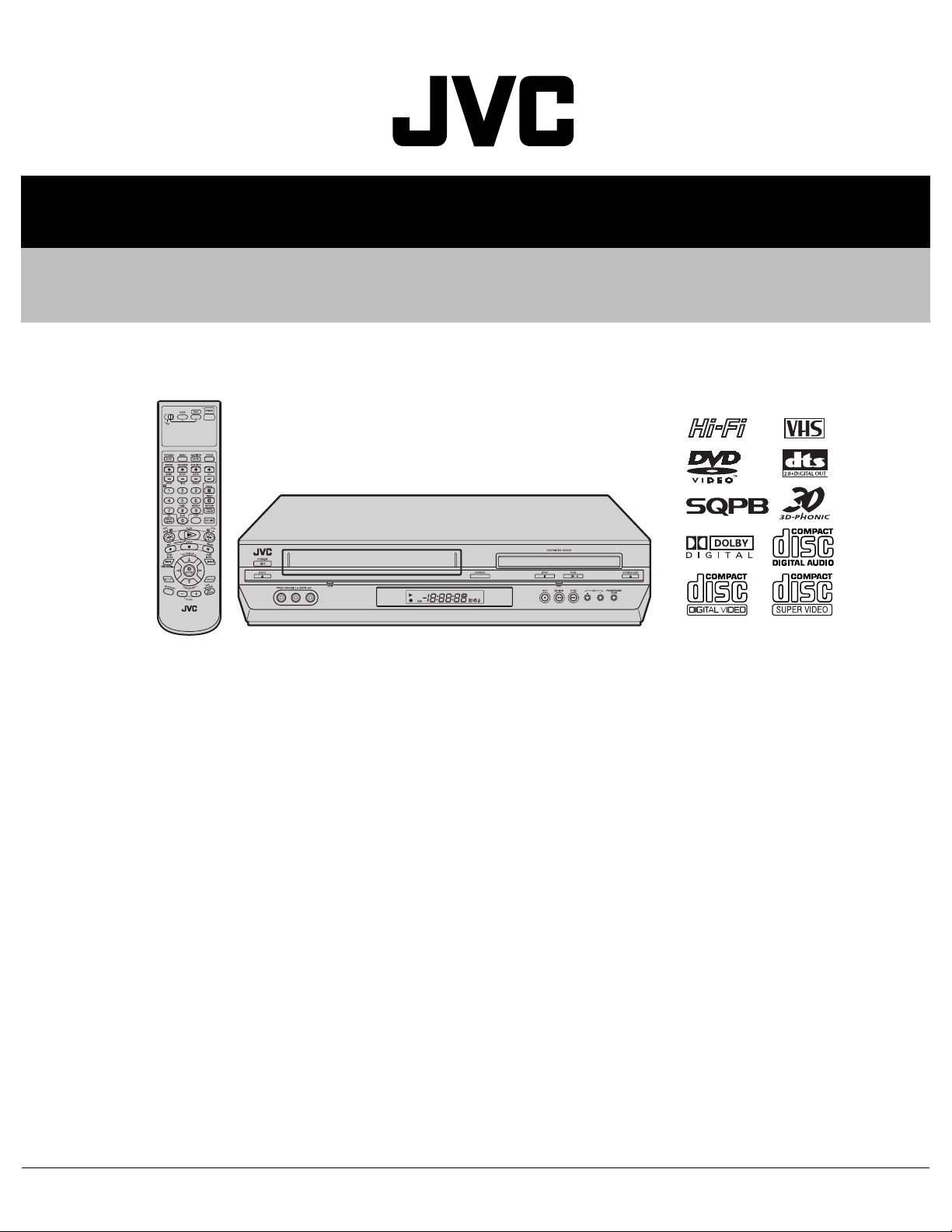
SERVICE MANUAL
DVD PLAYER & VIDEO CASSETTE RECORDER
YD03020047
HR-XVC37UC,HR-XVC37US
HR-XVC37UC,HR-XVC37US [D3PV2]
For disassembling and assembling of MECHANISM ASSEMBLY, refer to the SERVICE MANUAL No.86700 (MECHANISM ASSEMBLY).
Regarding service information other than these sections, refer to the service manual No. YD008 (HR-XVC26US).
Also, be sure to note important safety precautions provided in the service manual.
TABLE OF CONTENTS
1 PRECAUTION. . . . . . . . . . . . . . . . . . . . . . . . . . . . . . . . . . . . . . . . . . . . . . . . . . . . . . . . . . . . . . . . . . . . . . . . . 1-3
2 SPECIFIC SERVICE INSTRUCTIONS . . . . . . . . . . . . . . . . . . . . . . . . . . . . . . . . . . . . . . . . . . . . . . . . . . . . . . 1-3
3 DISASSEMBLY . . . . . . . . . . . . . . . . . . . . . . . . . . . . . . . . . . . . . . . . . . . . . . . . . . . . . . . . . . . . . . . . . . . . . . . 1-3
4 ADJUSTMENT . . . . . . . . . . . . . . . . . . . . . . . . . . . . . . . . . . . . . . . . . . . . . . . . . . . . . . . . . . . . . . . . . . . . . . . . 1-4
5 TROUBLESHOOTING . . . . . . . . . . . . . . . . . . . . . . . . . . . . . . . . . . . . . . . . . . . . . . . . . . . . . . . . . . . . . . . . . . 1-4
COPYRIGHT © 2004 Victor Company of Japan, Limited
No.YD030
2004/7
Page 2
SPECIFICATION
GENERAL
Power requirement AC 120 V, 60 Hz
Power consumption
Power on 26 W
Power off
Temperature
Operating 5
Storage -20
Operating position Horizontal only
Dimensions (W
Maximum recording time
VIDEO/AUDIO (VCR deck)
Recording system DA4 (Double Azimuth) head helical scan system
Signal-to-noise ratio 45 dB
Horizontal resolution 230 lines
VIDEO/AUDIO (DVD deck)
Audio characteristics DVD:4 Hz - 22 KHz
Frequency response CD:4 Hz - 20 KHz
Harmonic distortion 0.1%
CONNECTORS (VCR deck/DVD deck)
TUNER
Channel coverage VHF: Channels 2 - 13, UHF: Channels 14 - 69, CATV: 113 Channels
TIMER
Program capacity 1-year programmable timer/8 programs
Memory backup time Approx. 5 seconds
ACCESSORIES
Provided accessories RF cable, Infrared remote control unit, "AA" battery
× H × D) 435 mm x 93 mm x 272 mm
Weight
Format VHS NTSC standard
Signal system NTSC color signal and EIA monochrome signal, 525 lines/60 fields
Frequency range 70 Hz to 10,000 Hz (Normal audio) 20 Hz to 20,000 Hz (Hi-Fi audio)
Signal system NTSC
Applicable disc DVD (12 cm, 8 cm), CD (12 cm, 8 cm)
S/N Ratio 90 dB
Wow and flutter Below Measurable Level
Dynamic range 90 dB
Input/Output RCA connector IN x 1, OUT x 1
Tuning system Frequency synthesized tuner
RF output Channel 3 or 4 (switchable; preset to Channel 3 when shipped) 75 Ω, unbalanced
Clock reference Quartz
(SP) 210 min. with ST-210 video cassette
(EP) 630 min. with ST-210 video cassette
Component Video Out connector (Y, PB, PR) x 1
°C to 40°C (41°F to 104°F)
°C to 60°C (-4°F to 140°F)
S-video Output connector OUT x 1
Digital Audio (optical, coaxial) x 1
• Specifications shown are for SP mode unless otherwise specified.
• E.& O.E. Design and specifications subject to change without notice.
• Manufactured under license from Dolby Laboratories. "Dolby" and the double-D symbol are trademarks of Dolby Laboratories.
• "DTS" and "DTS 2.0 + Digital Out" are trademarks of Digital Theater Systems, Inc.
2.0 W
4.1 kg (9.041 Ib)
× 2
1-2 (No.YD030)
Page 3

SECTION 1
PRECAUTION
Please refer to "HR-XVC26US No.YD008" about this section.
SECTION 2
SPECIFIC SERVICE INSTRUCTIONS
Please refer to "HR-XVC26US No.YD008" about this section except a written item.
2.1 DIFFERENCE LIST
The following table indicates main different points between models HR-XVC26US, HR-XVC37UC and HR-XVC37US.
MODEL NAME HR-XVC26US HR-XVC37UC HR-XVC37US
BODY COLOR BLACK PURE SILVER ←
REMOCON COLOR BLACK GRAY ←
DIGITAL AUDIO OUTPUT COAXIAL(DVD ONLY)
COMPORNENT VIDEO OUTPUT DVD ONLY DVD/VCR ←
S- VIDEO OUTPUT DVD ONLY DVD/VCR ←
VHS/SVHS PROGRESSIVE NOT USED USED ←
COAXIAL/OPTICAL(DVD/VCR)
←
SECTION 3
DISASSEMBLY
Please refer to "HR-XVC26US No.YD008" about this section.
(No.YD030)1-3
Page 4

SECTION 4
ADJUSTMENT
Please refer to "HR-XVC26US No.YD008" about this section except a written item.
4.1 Electrical adjustment (VHS SECTION)
Note:
The following adjustment procedures are not only necessary
after replacement of consumable mechanical parts or board
assemblies, but are also provided as references to be referred
to when servicing the electrical circuitry.
In case of trouble with the electrical circuitry, always begin a
service by identifying the defective points by using the measuring instruments as described in the following electrical adjustment procedures. After this, proceed to the repair,
replacement and/or adjustment. If the required measuring instruments are not available in the field, do not change the adjustment parts (variable resistor, etc.) carelessly.
4.1.1 Servo circuit
4.1.1.1 Switching point
Signal (A1)
Mode (B) • PB
Equipment (C) • Oscilloscope
Measuring point (D1)
External trigger (E) • TP111 (D.FF)
Adjustment part (F) • Jig RCU: Code “5A”
Specified value (G) • 6.5 ± 0.5H
Adjustment tool (H) • Jig RCU [PTU94023B]
• Stairstep signal
(A2)
• Alignment tape(EP,stairstep,NTSC) [MHP-L]
• TP11 (J7002-pin8)
(D2)
• TP106 (PB. FM)
(1) Play back the signal (A1) of the alignment tape (A2).
(2) Apply the external trigger signal to D.FF (E) to observe the
VIDEO OUT waveform and V.PB FM waveform at the
measuring points (D1) and (D2).
(3) Set the VCR to the manual tracking mode.
(4) Adjust tracking so that the V.PB FM waveform becomes
maximum.
(5) Set the VCR to the Auto adjust mode by transmitting the
code (F) from the Jig RCU. When the VCR enters the stop
mode, the adjustment is completed.
(6) If the VCR enters the eject mode, repeat steps (1) to (5)
again.
(7) Play back the alignment tape (A2) again, confirm that the
switching point is the specified value (G).
Trigger point
Switching point
V.sync
V. rate
Fig.4-1a Switching point
TP11
(J7002-pin8)
CN7103
TP106
PB FM
TP 111
D.FF
MECHANISM ASSY
TP4001
CTL.P
A/C HEAD
TP2253
A.PB FM
CN2001
Fig.4-1b
1-4 (No.YD030)
SECTION 5
TROUBLESHOOTING
Please refer to "HR-XVC26US No.YD008" about this section.
Page 5

(No.YD030)1-5
Page 6

Victor Company of Japan, Limited
AV & MULTIMEDIA COMPANY DIGITAL VIDEO STORAGE CATEGORY 12, 3-chome, Moriya-cho, kanagawa-ku, Yokohama, kanagawa-prefecture, 221-8528, Japan
(No.YD030)
Printed in Japan
WPC
 Loading...