

Page 1
SERVICE MANUAL
VIDEO CASSETTE RECORDER
HR-S2110T/S6700KR/S7800U/U(C)
MBRSET
CABLE/
DBS
A/B
TV
POWER
TV/VCR
DISPLAY
A. MONITOR
123
2
456
DBS
DAILY(M-F)
WEEKLY
89
7
AUX
C.RESET
4
CANCEL
TIMER
0
START STOP DATE
CH
EXPRESS PROGRAMMING
PROG
PROG SP/EP SKIP SEARCH
1
CHECK
PLAY
F
W
F
E
R
R
T
V
V
O
L
–
C
E
NU
E
M
SHUTTLE
MULTI BRAND
REMOTE CONTROL UNIT
STOP
P
A
U
S
E
3
O
K
H
C
V
+
T
PLUS
+
L
O
V
V
T
–
T
H
V
C
POWER
S-VIDEO
DIGITAL TBC/NR
(MONO)L—AUDIO—RVIDEO
S-VHS ET
SP EP
VCR
Regarding service information other than these sections, refer to the HR-S4800U service manual (No. 82792).
Also, be sure to note important safety precautions provided in the service manual.
REW
MENU
CH
OK
FF
PLAY
REC
PAUSE
STOP/EJECT
SPECIFICATIONS
(The specifications shown pertain specifically to the model HR-S7800U)
GENERAL
Power requirement : AC 120 V` , 60 Hz
Power consumption
Power on : 20 W
Power off : 2.5 W
Temperature
Operating : 5°C to 40°C (41°F to 104°F)
Storage : –20°C to 60°C (–4°F to140°F)
Operating position : Horizontal only
Dimensions (W x H x D) : 400 mm x 94 mm x 281 mm
(15-3/4" x 3-3/4" x 11-1/8")
Weight : 3.5 kg (7.7 lbs)
Format : S-VHS/VHS NTSC standard
Maximum recording time
SP : 210 min. with ST-210 video cassette
EP : 630 min. with ST-210 video cassette
VIDEO/AUDIO
Signal system : NTSC-type color signal and EIA
monochrome signal, 525 lines/60 fields
Recording/
Playback system : DA-4 (Double Azimuth) head helical
scan system
Signal-to-noise ratio : 45 dB
Horizontal resolution
VHS : 230 lines
S-VHS : 400 lines
Frequency range
Normal audio : 70 Hz to 10,000 Hz
Hi-Fi audio : 20 Hz to 20,000 Hz
Input/Output : RCA connectors (IN x 2, OUT x 1)
S-video connectors (IN x 2, OUT x 1)
TUNER
Tuning system : Frequency-synthesized tuner
Channel coverage
VHF : Channels 2–13
UHF : Channels 14–69
CATV : 113 Channels
RF output : Channel 3 or 4 (switchable; preset
to Channel 3 when shipped) 75 Ω,
unbalanced
TIMER
Clock reference : Quartz
Program capacity : 1-year programmable timer/
8 programs
Memory backup time : Approx. 3 min.
ACCESSORIES
Provided accessories : Infrared remote control unit,
“AA” battery x 2,
Audio/video cable,
RF cable (F-type),
S-video cable (4-pin),
S-VHS ET labels,
Controller
Specifications shown are for SP mode unless specified otherwise.
E. & O.E. Design and specifications subject to change without notice.
This service manual is made from all recycled paper.
COPYRIGHT © 2000 VICTOR COMPANY OF JAPAN, LTD.
No. 82806
May 2000
Page 2
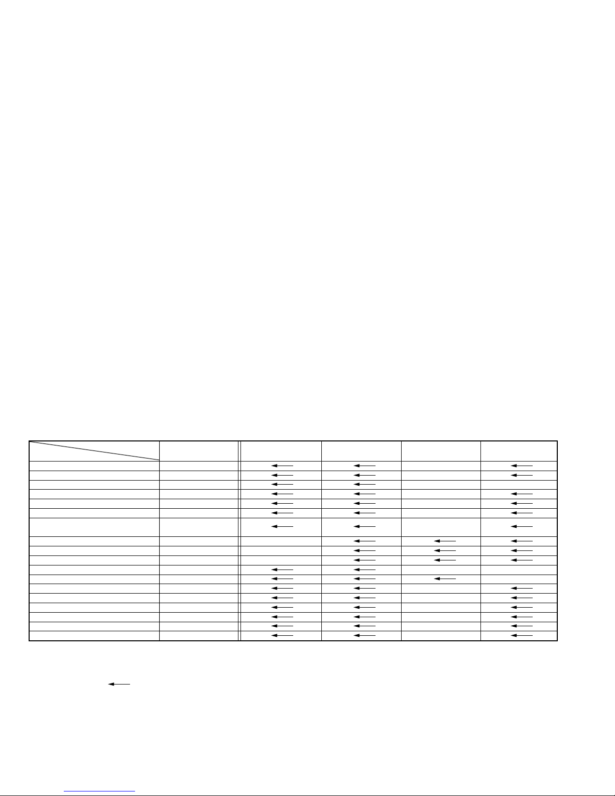
TABLE OF CONTENTS
DIFFERENT TABLE .................................................................................................................................................................................... 1 to 5
3. ELECTRICAL ADJUSTMENT (3-1 to 3-7)
3.1 PRECAUTION ........................................................................................................................................................................................ 3-1
3.2 SERVO CIRCUIT ................................................................................................................................................................................... 3-2
3.3 VIDEO CIRCUIT .................................................................................................................................................................................... 3-2
3.4 AUDIO CIRCUIT .................................................................................................................................................................................... 3-4
3.5 DEMODULATOR CIRCUIT .................................................................................................................................................................... 3-5
3.6 SYSCON CIRCUIT ................................................................................................................................................................................ 3-7
4. CHARTS AND DIAGRAM (4-1 to 4-12)
4.1 BOARD INTERCONNECTIONS ............................................................................................................................................................ 4-1
4.2 3D DIGITAL/2M SCHEMATIC DIAGRAM .............................................................................................................................................. 4-3
4.3 DEMODULATOR SCHEMATIC DIAGRAM [HR-S6700KR] ................................................................................................................... 4-5
4.4 MAIN,A/C HEAD, S JACK, R.PAUSE, C.BOX AND LOADING MOTOR CIRCUIT BOARDS ............................................................... 4-7
4.5 3D DIGITAL/2M CIRCUIT BOARD ...................................................................................................................................................... 4-10
4.6 DEMODULATOR CIRCUIT BOARD [HR-S6700KR] ........................................................................................................................... 4-11
4.7 REMOTE CONTROL SCHEMATIC DIAGRAM [HR-S2110T/S6700KR] ............................................................................................. 4-12
5. PARTS LIST (5-1 to 5-4)
5.1 CABINET AND CHASSIS ASSEMBLY <M2> ........................................................................................................................................ 5-1
5.2 ELECTRICAL PARTS LIST .................................................................................................................................................................... 5-3
The following table indicate main different points between models HR-S4800U, HR-S7800U, HR-S7800U(C), HR-S6700KR
and HR-S2110T.
ITEM
JOG/SHUTTLE DIAL ON DECK SH/PLAY J/S
POWER VOLTAGE (RATING) 120V,60Hz 110 `220V(60Hz)
POWER PLUG UL,CSA KOREAN SASO
POWER SAVE USED NOT USED
FRONT PANEL COLOR BLACK CHMP
HEAD CLEANER NOT USED USED
RECORDING & PLAYBACK SPEED
DIGITAL 3R NOT USED USED
TBC NOT USED USED
3D-MEMORY NOT USED USED
STEREO DECODER MTS A2(KOREAN) MTS
RF OUT CH [3CH],4CH 13CH
SUMMER TIME ADJ. USED NOT USED
CHILD LOCK USED NOT USED
VCR PLUS+ VCR+C3 G-CODE
AUTO CLOCK USED NOT USED
JUST CLOCK USED NOT USED
CABLE & DBS BOX CONTROL USED NOT USED
Notes : Mark
MODEL
is same as left.
HR-S4800U HR-S7800U HR-S7800U(C) HR-S6700KR HR-S2110T
REC: SP/EP,
PLAY: SP/LP/EP
SP/EP
Mark — is not used.
1
Page 3
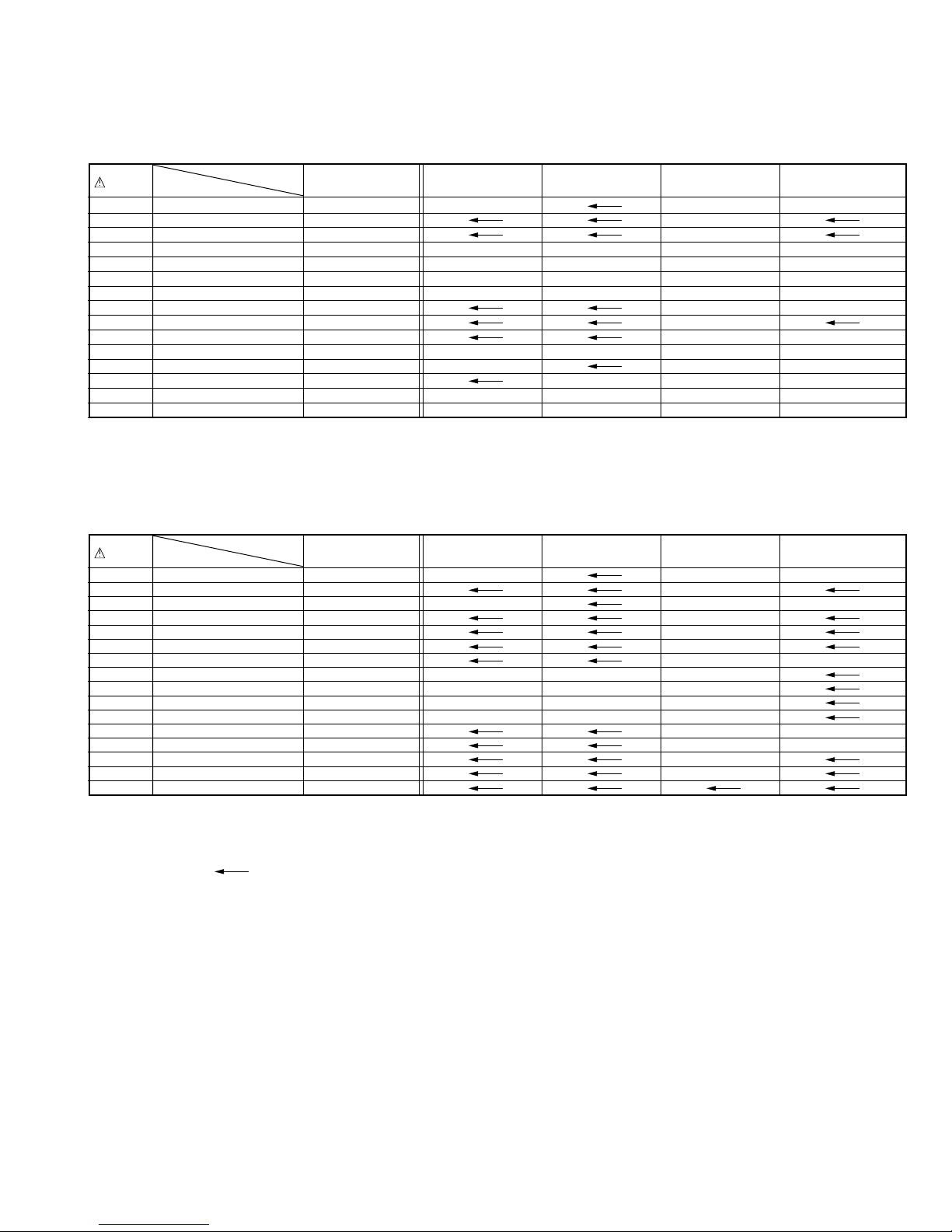
The following table indicate different parts number between models HR-S4800U, HR-S7800U, HR-S7800U(C), HR-S6700KR
and HR-S2110T.
PACKING AND ACCESSORY ASSEMBLY <M1>
REF. MODEL
NO. ITEM
301 PACKING CASE LP30658-013A LP30658-022A LP30658-026A LP30658-029A
306 REMOTE CONTROLLER LP20303-015A LP20878-004B
306A COVER(BATTERY) LP40225-002A LP40610-002A
! 310 INST.BOOK(EN) LPT0348-001A LPT0349-001A ———
! 310 INST.BOOK(FR) ——LPT0349-003A ——
! 310 INST.BOOK(KO) ———LPT0430-001A —
! 310 INST.BOOK(EN.CH) ————LPT0429-001A
313 A/V CABLE PEAC0359-120 ——
314 S CABLE QAM0004-002 QAM0246-002
315 CONTROLLER QAL0095-005 ——
316 WARRANTY CARD ——BT-52004-1 BT-56009-2M —
317 Q.S.SHEET LPT0348-002A LPT0349-002A ——
319 REGIST.CARD BT-51020-2 ———
320 SER.NET CARD ——BT-20071B ——
323 CONNECTION SHEET ——PU36560 ——
HR-S4800U HR-S7800U HR-S7800U(C) HR-S6700KR HR-S2110T
CABINET AND CHASSIS ASSEMBLY <M2>
REF. MODEL
NO. ITEM
! 501 FRONT PANEL ASSY LP10289-019B LP10289-020C LP10289-039B LP10289-042B
501A CASSETTE DOOR LP20868-005A LP20868-017A
501C DISPLAY WINDOW LP20869-023A LP20869-024A LP20869-052A LP20869-060A
! 502 TOP COVER LP10013-021D LP10013-031C
503 TAP SCREW QYTDSF3010M QYTDSF3010R
! 511 BOTTOM CHASSIS LP10108-012B LP10108-016A
! 517 POWER CORD QMPD190-170-K PQ21730N QMP73J0-170
518 CLEANER ASSY ———LP40369-001D
518A CLEANER ROLLER ———PQ46418-1-2
518B CLEANER ———PQ46419-1-2
518C CLEANER ARM ———LP30407-001D
527 WASHER,DRUM QYWW267505Z ——
528 SPACER,DRUM LP30017-21A ——
529 KNOB(JOG) LP30653-001A LP30651-004A
530 KNOB(SHUTTLE) LP30652-001A LP30652-002A
533
SPACER, SHIELD FRAME*LP30002-088A
HR-S4800U HR-S7800U HR-S7800U(C) HR-S6700KR HR-S2110T
Notes : Mark is same as left.
Mark — is not used.
Mark
HR-S4800U was also changed.
*
2
Page 4
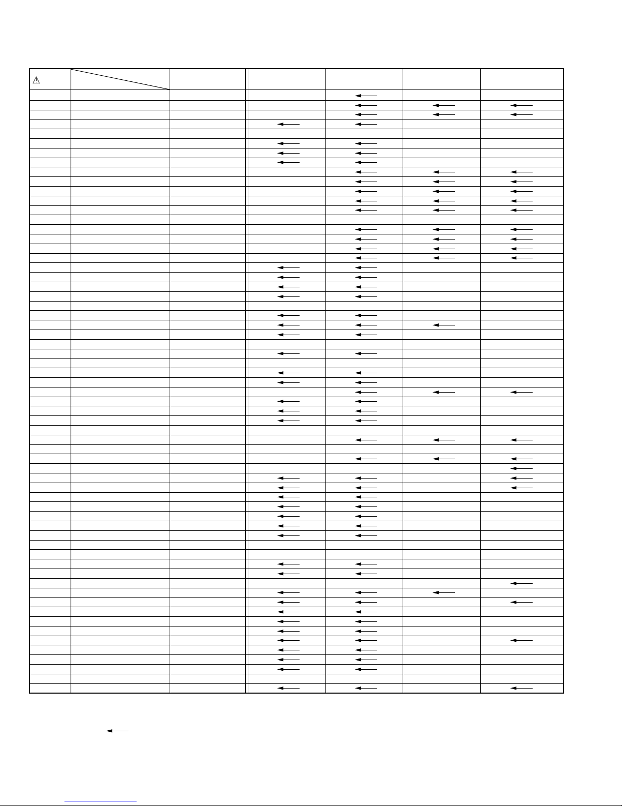
MAIN BOARD ASSEMBLY <03>
REF. MODEL
NO. ITEM
PW1 MAIN BOARD ASSY LPA10089-01B1 LPA10089-06B1 LPA10089-08B1 LPA10089-13A1
IC3001 IC MN101D02HJP MN101D02HAA
IC3004 IC M24C04-BN6 M24C08-BN6
IC5101 IC STR-G6532 STR-G6551 STR-G6532
Q6030 TRANSISTOR ———2SB1218A/QR/-X —
Q6551 TRANSISTOR
Q7201 TRANSISTOR 2SA720/RS/-T ——
D6551 Z DIODE MTZJ10B-T2 — MTZJ10B-T2
D7005 SI DIODE — 1SS133-T2
D7010 LED — SLR-325MC-T
R31 MG RESISTOR NRSA02J-152X NRSA02J-122X
R46 MG RESISTOR NRSA02J-471X NRSA02J-271X
R75 MG RESISTOR — NRSA02J-225X
R111 MG RESISTOR NRSA02J-222X ————
R3029 MG RESISTOR — NRSA02J-0R0X
R3032 MG RESISTOR — NRSA02J-0R0X
R3045 MG RESISTOR — NRSA02J-102X
R3093 MG RESISTOR — NRSA02J-0R0X
R5001 RESISTOR QRZ9046-475Z ——
R5102 RESISTOR QRE141J-300Y QRE141J-100Y QRE141J-300Y
R5104 OMF RESISTOR QRG02GJ-683 QRG02GJ-473 QRG02GJ-683
R5306 MG RESISTOR NRSA02J-563X NRSA02J-823X NRSA02J-563X
R6030 MG RESISTOR ———NRSA02J-332X —
R6032 MG RESISTOR NRSA02J-123X — NRSA02J-123X
R6053 MG RESISTOR NRSA02J-102X —
R6508 MG RESISTOR NRSA02J-0R0X NRSA02J-682X NRSA02J-0R0X
R6509 MG RESISTOR ———NRSA02J-682X —
R6510 MG RESISTOR NRSA02J-0R0X NRSA02J-682X NRSA02J-0R0X
R6511 MG RESISTOR ———NRSA02J-682X —
R6551 MG RESISTOR NRSA02J-271X — NRSA02J-271X
R6552 MG RESISTOR NRSA02J-101X — NRSA02J-101X
R7041 MG RESISTOR — NRSA02J-331X
R7202 RESISTOR QRE141J-471Y ——
R7203 MG RESISTOR NRSA02J-222X ——
R7204 RESISTOR QRE123J-100X ——
C18 E CAPACITOR QEKJ1HM-105 ————
C63 CAPACITOR NCB21EK-104X NCB21EK-473X
C128 MG RESISTOR NRSA02J-0R0X ———NRSA02J-0R0X
C561 E CAPACITOR — QERF1HM-105Z
C3018 TRIM CAPACITOR ———QAT3725-300Z
C3019 CAPACITOR NDC21HJ-180X NDC21HJ-100X
C5004 CAPACITOR QCZ9094-472 QCZ9071-222
C5006 E CAPACITOR QETM2DM-157 QEZ0374-826 QETM2DM-157
C5102 E CAPACITOR QEMT1VM-276 QEMU1VM-276Z QEMT1VM-276
C5103 CAPACITOR QCZ0302-470Z QCZ0302-330Z QCZ0302-470Z
C5304 MF CAPACITOR QFVF1HJ-124Z QFVF1HJ-224Z QFVF1HJ-124Z
C5310 M CAPACITOR QFLC1HJ-183Z — QFLC1HJ-183Z
C6519 CAPACITOR ———NCB21EK-223X —
C6520 CAPACITOR ———NCB21EK-223X —
C7206 E CAPACITOR QEKJ0JM-227Z ——
L7201 P COIL QQL29BJ-101Z ——
X3002 CRYSTAL ———QAX0445-001
S6050 SLIDE SWITCH QSW0460-001 —
! PC5101 IC(PHOTO COUPLER) PS2501-1 PS2561L1-1/WL/
TU6001 TUNER QAU0163-001 QAU0125-001 QAU0177-001
! TB1 TERMINAL BOARD LP20887-002B LP20887-006A LP20887-007A
FW3002
J7101 PIN JACK QNN0288-001 QNN0288-002
! SG5001 SURGE ABSORBER QAF0046-242Z ——
! VA5001 VARISTOR QAF0023-431Z ——
! VA5002 VARISTOR QAF0023-431Z ——
! VA5003 VARISTOR ———QAF0026-621 —
! F5001 FUSE QMF51N2-1R25J1 QMF51E2-2R0
PARA RIBON WIRE QUM022-30A4A4 ——
HR-S4800U HR-S7800U HR-S7800U(C) HR-S6700KR HR-S2110T
2SC1740S/QRS/-T
— 2SC1740S/QRS/-T
Notes : Mark
is same as left.
Mark — is not used.
3
Page 5
2D DIGITAL BOARD ASSEMBLY <05>
REF. MODEL
NO. ITEM
PW1
2D DIGITAL BOARD ASSY
HR-S4800U HR-S7800U HR-S7800U(C) HR-S6700KR HR-S2110T
LPA10090-01B ————
3D DIGITAL/2M BOARD ASSEMBLY <05>
REF. MODEL
NO. ITEM
PW1
3D DIGITAL/2M BOARD ASSY
HR-S4800U HR-S7800U HR-S7800U(C) HR-S6700KR HR-S2110T
— LPA10105-02A
R.PAUSE BOARD ASSEMBLY <06>
REF. MODEL
NO. ITEM
PW2 R.PAUSE BOARD ASSY LPA10089-01B2 LPA10089-01C2
HR-S4800U HR-S7800U HR-S7800U(C) HR-S6700KR HR-S2110T
DEMOD BOARD ASSEMBLY <14>
REF. MODEL
NO. ITEM
PW1 DEMOD BOARD ASSY PB11076A PB11091A PB11076A
IC1501 IC UPC1852AGT KA2268 UPC1852AGT
Q1501 TRANSISTOR ———2SC1740S/QRS/-T —
Q1502 DIGI TRANSISTOR ———DTC144WSA —
R1501 MG RESISTOR QRE141J-102Y NRSA02J-471X QRE141J-102Y
R1502 MG RESISTOR QRE141J-334Y NRSA02J-102X QRE141J-334Y
R1503 MG RESISTOR QRE141J-124Y NRSA02J-822X QRE141J-124Y
R1504 MG RESISTOR QRE141J-302Y NRSA02J-103X QRE141J-302Y
R1505 MG RESISTOR QRE141J-512Y NRSA02J-473X QRE141J-512Y
R1506 MG RESISTOR QRE141J-333Y NRSA02J-101X QRE141J-333Y
R1507 MG RESISTOR QRE141J-333Y NRSA02J-102X QRE141J-333Y
R1508 MG RESISTOR QRE141J-392Y NRSA02J-273X QRE141J-392Y
R1509 MG RESISTOR QRE141J-122Y NRSA02J-103X QRE141J-122Y
R1510 MG RESISTOR QRE141J-392Y NRSA02J-563X QRE141J-392Y
R1511 MG RESISTOR QRE141J-122Y NRSA02J-562X QRE141J-122Y
R1512 MG RESISTOR ———NRSA02J-332X —
R1513 MG RESISTOR ———NRSA02J-123X —
R1514 MG RESISTOR ———NRSA02J-123X —
R1515 MG RESISTOR ———NRSA02J-562X —
R1516 MG RESISTOR ———NRSA02J-273X —
R1517 MG RESISTOR QRE141J-123Y NRSA02J-103X QRE141J-123Y
R1518 MG RESISTOR ———NRSA02J-102X —
R1520 MG RESISTOR ———NRSA02J-102X —
R1521 MG RESISTOR ———NRSA02J-471X —
VR1501 V RESISTOR ———QVPA606-103Z —
VR1502 TRIM RESISTOR ———QVP0039-683Z —
C1501 CAPACITOR QETC1CM-226Z NCB21EK-473X QETC1CM-226Z
C1502 E CAPACITOR QETC1HM-104Z QEKC1CM-106Z QETC1HM-104Z
C1503 CAPACITOR QETC1HM-105Z NCB21HK-471X QETC1HM-105Z
C1504 E CAPACITOR QETC1HM-475Z — QETC1HM-475Z
C1505 CAPACITOR QETC1HM-225Z NDC21HJ-470X QETC1HM-225Z
C1506 CAPACITOR QETC1HM-104Z NDC21HJ-470X QETC1HM-104Z
C1507 CAPACITOR QFV11HJ-473Z NCB21EK-104X QFV11HJ-473Z
C1508 MF CAPACITOR QETC1HM-474Z QFV11HJ-124Z QETC1HM-474Z
C1509 CAPACITOR QETC1HM-104Z NCB21EK-104X QETC1HM-104Z
C1510 CAPACITOR QETC1HM-105Z NCB21EK-473X QETC1HM-105Z
C1511 E CAPACITOR QETC1HM-105Z — QETC1HM-105Z
C1512 CAPACITOR QETC1HM-105Z NCB21EK-683X QETC1HM-105Z
C1513 E CAPACITOR QETN1HM-335Z QEKC1EM-475Z QETN1HM-335Z
C1514 E CAPACITOR QETN1HM-106Z QEKC1EM-475Z QETN1HM-106Z
C1515 M CAPACITOR QETC1HM-105Z QFLC1HJ-683Z QETC1HM-105Z
C1516 CAPACITOR QETC1HM-106Z NCB21EK-473X QETC1HM-106Z
C1517 E CAPACITOR QETC1HM-106Z QETC1CM-227Z QETC1HM-106Z
C1518 E CAPACITOR QETC1HM-105Z QETC1CM-106Z QETC1HM-105Z
HR-S4800U HR-S7800U HR-S7800U(C) HR-S6700KR HR-S2110T
Notes : Mark is same as left.
Mark — is not used.
4
Page 6
REF. MODEL
NO. ITEM
C1519 E CAPACITOR ———QETC1CM-106Z —
C1520 E CAPACITOR ———QETC1CM-106Z —
C1521 E CAPACITOR QETC1HM-106Z — QETC1HM-106Z
C1522 E CAPACITOR ———QEKC1CM-106Z —
C1523 CAPACITOR ———NCB21HK-332X —
C1524 E CAPACITOR ———QETC1CM-227Z —
C1526 CAPACITOR ———NDC21HJ-470X —
C1527 CAPACITOR ———NDC21HJ-470X —
C1528 E CAPACITOR ———QEKC1CM-106Z —
C1530 CAPACITOR ———NCB21EK-473X —
L1501 P COIL ———QQL01BJ-680Z —
HR-S4800U HR-S7800U HR-S7800U(C) HR-S6700KR HR-S2110T
SUTTLE BOARD ASSEMBLY <85>
REF. MODEL
NO. ITEM
PW1 SUTTLE BOARD ASSY LPA20006-02A LPA20006-01A
UN7001 JOG SHUTTLE SW PESW0679 QSW0845-001
HR-S4800U HR-S7800U HR-S7800U(C) HR-S6700KR HR-S2110T
C.BOX BOARD ASSEMBLY <92>
REF. MODEL
NO. ITEM
PW3 C.BOX BOARD ASSY LPA10089-01B3 LPA10089-01C3 ——
HR-S4800U HR-S7800U HR-S7800U(C) HR-S6700KR HR-S2110T
5
Page 7
SECTION 3
ELECTRICAL ADJUSTMENT
3.1 PRECAUTION
The following adjustment procedures are not only necessary
after replacement of consumable mechanical parts or board
assemblies, but are also provided as references to be referred
to when servicing the electrical circuitry.
In case of trouble with the electrical circuitry, always begin a
service by identifying the defective points by using the measuring instruments as described in the following electrical adjustment procedures. After this, proceed to the repair, replacement and/or adjustment. If the required measuring instruments are not available in the field, do not change the
adjustment parts (variable resistor, etc.) carelessly.
3.1.1 Required test equipments
• Color (colour) television or monitor
• Oscilloscope: wide-band, dual-trace, triggered delayed
sweep
• Frequency counter
• Audio level meter
• Signal generator: RF / IF sweep / marker
• Signal generator: stairstep, color (colour) bar [NTSC]
• Recording tape
• Digit-key remote controller(provided)
3.1.2 Required adjustment tools
Jig RCU
PTU94023B
Alignment tape
(SP, stairstep, NTSC)
MHP
Jig RCU
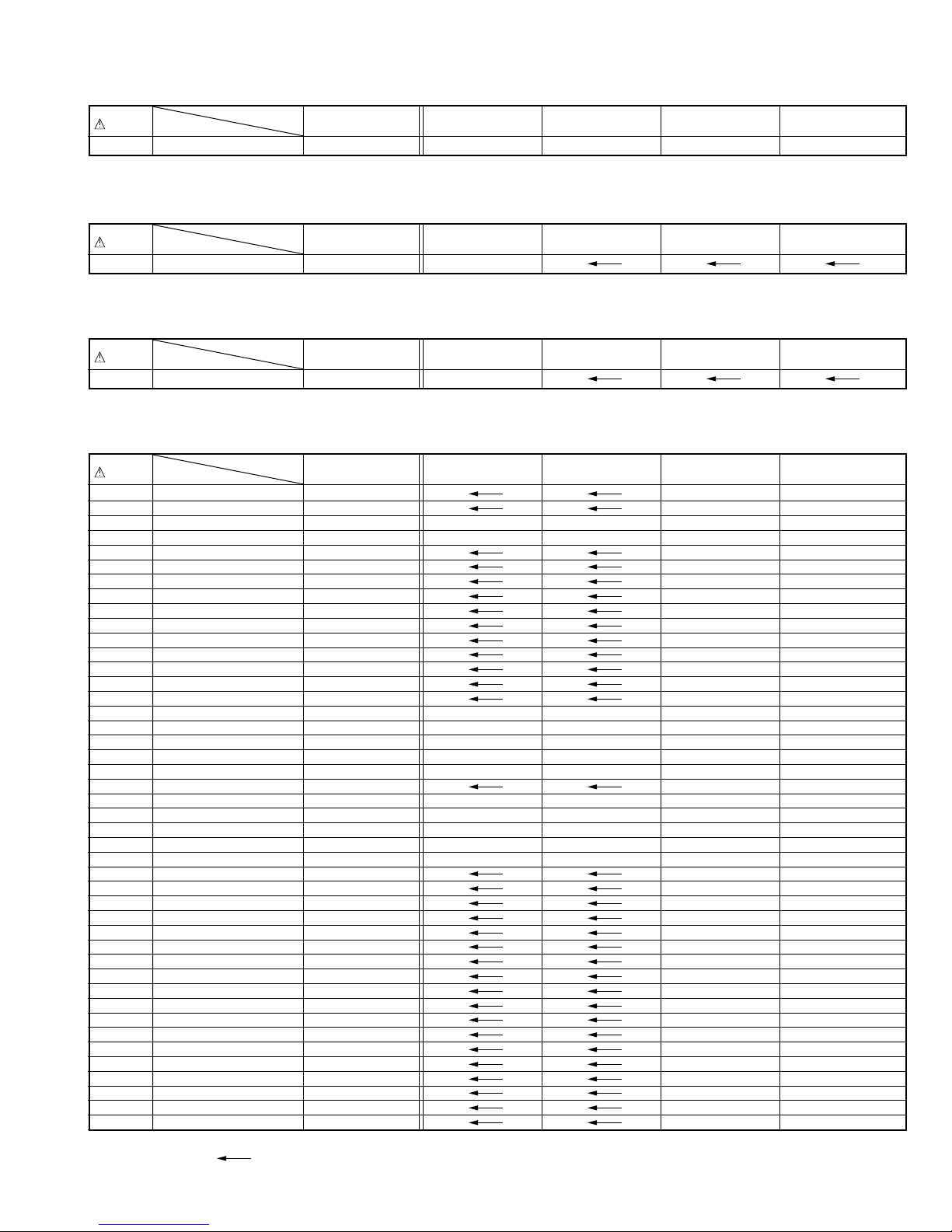
INITIAL MODE
DATA CODE
[Data transmitting method]
Depress the “ ” ( 3 ) button
after the data code is set.
CUSTOM CODE
43: A CODE
53: B CODE
Fig. 3-1-4a Jig RCU
•
Set the switches as shown below unless otherwise
specified on the relevant adjustment chart. The
switches that are not listed below can be set as desired.
If the VCR is not equipped with the functions detailed
below, setup is not required.
AUTO PICTURE/VIDEO CALIBRATION/
OFF
B.E.S.T./D.S.P.C.
PICTURE CONTROL/SMART PICTURE
NORMAL/NATURAL
VIDEO STABILIZER OFF
TBC ON
Digital 3R ON
•
Unless otherwise specified, all measuring points and
adjustment parts are located on the Main board.
•
In the Signal column of the adjustment chart, “Ext. Sinput” means the Y/C separated video signal and “Ext.
input” means the composite video signal input.
LPF
PTU93006
3.1.3
Color (colour) bar signal,Color (colour) bar pattern
s
Color bar signal [NTSC]
White(100%)
White(75%)
100 IRE
1V
40 IRE
Horizontal sync
Yellow
Cyan
Green
Magenta
QI
Alignment tape
(S-VHS SP/EP, color (colour) bar)
MH-1H
s
Red
Burst
Blue
40 IRE
Color bar pattern [NTSC]
(75%)
Green
Magenta
Red
Cyan
White
Yellow
White
Q I Black
100%
3.1.4 Switch settings and standard precautions
The SW settings of the VCR and the standard precautions
for the electrical adjustments are as follows.
When using the Jig RCU, set its custom code to match
•
the custom code of the VCR.
Blue
3.1.5 EVR Adjustment
Some of the electrical adjustments require the adjustment
performed by the EVR system. The Main board assembly
have EEPROMs for storing the EVR adjustment data and user
setups.
Notes:
•
In the EVR adjustment mode, the value is varied with
the channel buttons (+, –). The adjusted data is stored
when the setting mode changes (from PB to STOP,
when the tape speed is changed, etc.). Take care to
identify the current mode of each adjustment item
when making an adjustment.
•
When changing the address setting in the EVR adjustment mode, use the Jig RCU or the remote controller
having numeric keypad with which a numeric code can
be directly input.
The remote control code of the Jig RCU corresponds
to each of the digit keys on the remote controller as
follows.
Digit-key 0 1 2 3 4 5 6 7 8 9
Code 20 21 22 23 24 25 26 27 28 29
•
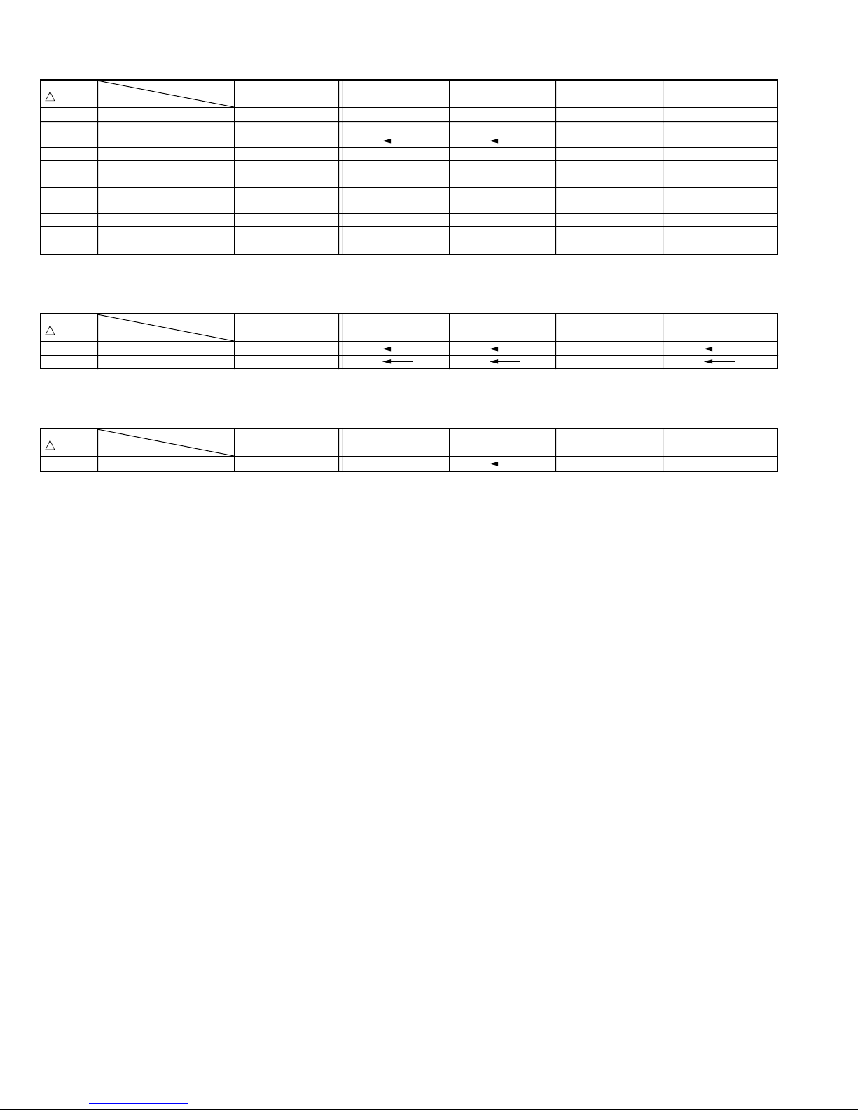
As the counter indication and remaining tape indication are not displayed FDP during the EVR adjustment
mode, check them on the TV monitor screen.
•
When performing the EVR adjustment, confirm that the
FDP indication is changed to the EVR mode, as shown
below.
3-1
Page 8
FDP
Fig. 3-1-5a EVR mode
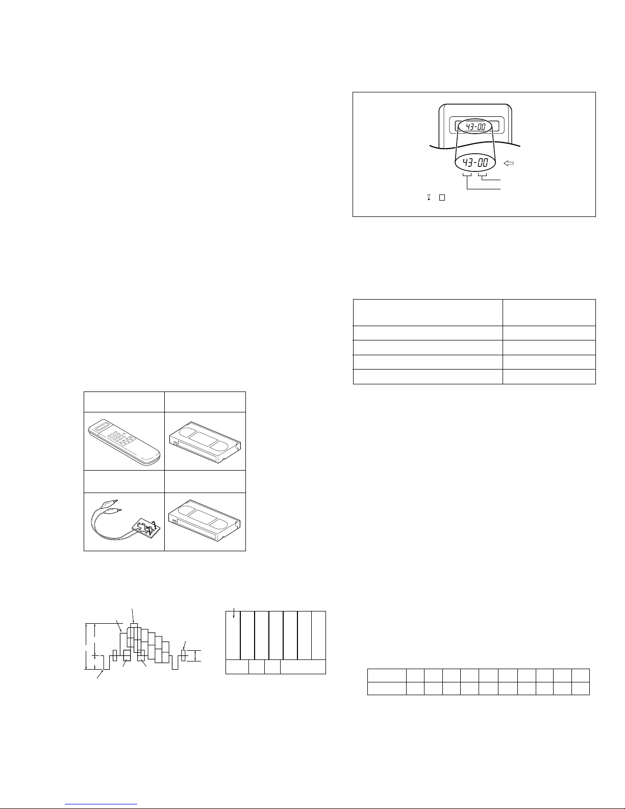
3.2 SERVO CIRCUIT
3.2.1 Switching point
Signal (A1) • Stairstep signal
Mode (B) • PB
Equipment (C) • Oscilloscope
Measuring point (D1) •
External trigger (E) • TP111 (D.FF)
Adjustment part (F) • Jig RCU: Code “5A”
Specified value (G) • 7.5 ± 0.5H [MHP]
Adjustment tool (H) • Jig RCU [PTU94023B]
(A2) • Alignment tape [MHP]
• TBC: OFF
VIDEO OUT terminal (75Ø terminated)
(D2) • TP106 (PB. FM)
(1) Play back the signal (A1) of the alignment tape (A2).
(2) Apply the external trigger signal to D.FF (E) to observe
the VIDEO OUT waveform and V.PB FM waveform at
the measuring points (D1) and (D2).
(3) Press the channel buttons (+, –) simultaneously to enter
the manual tracking mode. This also brings tracking to
the center (centre).
(4) Adjust tracking by pressing the channel buttons (+, –) so
that the V.PB FM waveform becomes maximum.
(5) Set the VCR to the Auto adjust mode by transmitting the
code (F) from the Jig RCU. When the VCR enters the
stop mode, the adjustment is completed.
(6) If the VCR enters the eject mode, repeat steps (1) to (5)
again.
(7) Play back the alignment tape (A2) again, confirm that the
switching point is the specified value (G).
Trigger point
Switching point
V.sync
V. rate
(1) Record the signal (A2) in the mode (B1), and play back
the recorded signal.
(2) Press the channel buttons (+, –) simultaneously to enter
the manual tracking mode. This also brings tracking to
the center (centre).
(3) Set the VCR to the FWD slow mode.
(4) Transmit the code (F) from the Jig RCU to adjust so that
the noise bar becomes the specified value (G) on the TV
monitor in the slow mode.
(5) Set the VCR to the Stop mode.
(6) Confirm that the noise bar is (G) on the TV monitor in
the slow mode.
(7) Repeat steps (3) to (6) in the REV slow mode.
(8) Repeat steps (1) to (7) in the mode (B2).
Note:
For FWD slow playback, transmit the code “08” from
•
the Jig RCU to enter the slow playback mode, and
transmit the code “D0” for REV slow mode.
3.3 VIDEO CIRCUIT
3.3.1 D/A level
Signal (A1) • Ext. S-input / Ext. input
(A2) • Color (colour) bar signal [NTSC]
(A3) • S-VHS tape
Mode (B) • S-VHS
• EE
Equipment (C) • Oscilloscope
Measuring point (D) •
Adjustment part (F) •
Specified value (G) • 1.00 ± 0.015 Vp-p (reference value)
(Note)
VIDEO OUT terminal (75Ø terminated)
VR1401 (DA Y LEVEL ADJ) [3D board]
(1) Insert the cassette tape (A3) to enter the mode (B).
(2)
Observe the VIDEO OUT waveform at the measuring
point (D).
(3) Check the Y level value when the External S-input (Y/C
separated video signal).
(4) Switch the input signal to the External input (composite
video signal), and adjust the adjustment part (F) so that
the Y level becomes the same value observed in step
(3).
Note:
The specified value (G) is just a reference value to be
•
obtained when the External S-Video (Y/C separated
video) signal is input. In actual adjustment, set it to the
value observed in step (3).
Fig. 3-2-1a Switching point
3.2.2 Slow tracking preset
Signal (A1) • Ext. input
Mode (B1) • S-VHS SP
Measuring point (D) • TV-Monitor
Adjustment part (F) • Jig RCU: Code “71“ or “72”
Specified value (G) • Minimum noise
Adjustment tool (H) • Jig RCU [PTU94023B]
3-2
(A2) • Color (colour) bar signal [NTSC]
(B2) • S-VHS EP
Y level
H. rate
Fig. 3-3-1a D/A level
Page 9

3.3.2 EE Y level
H. rate
Y level
1 kØ 39 µH 180 µH
120 pF 180 pF
PB. FM
629 [kHz]
PB COLOR
(PB COLOUR)
Signal (A1) • Ext. input
Mode (B) • EE
Equipment (C) • Oscilloscope
Measuring point (D) • Y OUT terminal (75Ø terminated)
EVR mode (F1) • Jig RCU: Code “57”
EVR address (F2) •
Specified value (G) • 1.00 ± 0.03 Vp-p
Adjustment tool (H) • Jig RCU [PTU94023B]
(1)
Observe the Y OUT waveform at the measuring point (D).
(A2) • Color (colour) bar signal [NTSC]
A:11 (Press remote controller “1” key twice)
• Digit-key remote controller
(2) Set the VCR to the EVR mode by transmitting the code
(F1) from the Jig RCU.
(3) Set the EVR address to (F2) by pressing the button of
the digit-key remote controller.
(4) Adjust with the channel buttons (+, –) on the VCR (or on
the remote controller) so that the Y level of the Y OUT
waveform becomes the specified value (G).
(5) Release the EVR mode of the VCR by transmitting the
code (F1) from the Jig RCU again. (When the EVR mode
is released, the adjusted data is memorized.)
Y level
Fig. 3-3-3a PB Y level
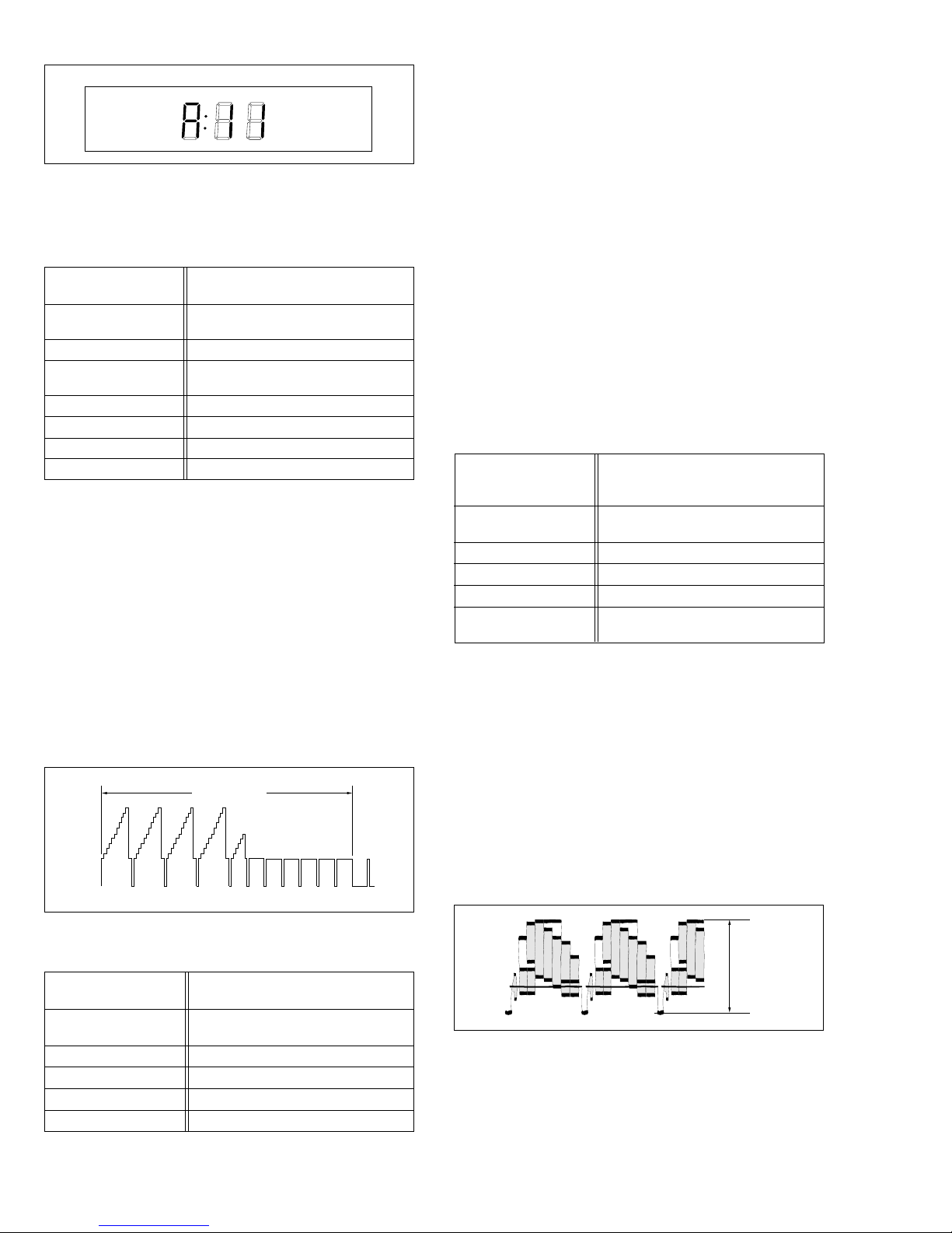
3.3.4 REC color (colour) level
Signal (A1) • Alignment tape [MH-1H]
(A2) • Ext. input
(A3) • Color (colour) bar signal [NTSC]
Mode (B1) •S-VHS SP
(B2) • S-VHS EP
Equipment (C) • Oscilloscope
Measuring point (D1) • TP106 (PB. FM)
(D2) • PB color (colour) output of the LPF
External trigger (E) • TP111 (D.FF)
EVR mode (F1) • Jig RCU: Code “57”
EVR address (F2) • A:02 (Press remote controller
“0” and “2” keys)
Specified value (G) • SP: “B” x 125 ± 5%
• EP: “B” x 125 ± 5%
Adjustment tool (H1) • Jig RCU [PTU94023B]
(H2) • Digit-key remote controller
(H3) • LPF [PTU93006] (See Fig. 3-3-4a.)
H. rate
Fig. 3-3-2a EE Y level
3.3.3 PB Y level (S-VHS / VHS)
Signal (A1) • Ext. input
Mode (B1) • S-VHS SP
Equipment (C) • Oscilloscope
Measuring point (D) • Y OUT terminal (75Ø terminated)
EVR mode (F1) • Jig RCU: Code “57”
EVR address (F2) •
Specified value (G) • 1.00 ± 0.03 Vp-p
Adjustment tool (H) • Jig RCU [PTU94023B]
(A2) • Color (colour) bar signal [NTSC]
(B2) • VHS SP
A:11 (Press remote controller “1” key twice)
• Digit-key remote controller
(1) Observe the Y OUT waveform at the measuring point (D).
(2) Record the signal (A2) in the mode (B1), and play back
the recorded signal.
(3) Press the channel buttons (+, –) simultaneously to enter
the manual tracking mode. This also brings tracking to
the center (centre).
(4) Set the VCR to the EVR mode by transmitting the code
(F1) from the Jig RCU.
(5) Set the EVR address to (F2) by pressing the button of
the digit-key remote controller.
(6) Adjust with the channel buttons (+, –) on the VCR (or on
the remote controller) so that the Y level of the Y OUT
waveform becomes the specified value (G).
(7) Release the EVR mode of the VCR by transmitting the
code (F1) from the Jig RCU again. (When the EVR mode
is released, the adjusted data is memorized.)
(8) Repeat steps (2) to (7) in the mode (B2).
Fig. 3-3-4a LPF
(1) Connect the adjustment tool (H3) to the measuring point (D1).
(2) Apply the external trigger signal to D.FF (E) to observe the
PB color (colour) waveform at the measuring point (D2).
(3) Play back the signal (A3) in the mode (B1) of the align-
ment tape (A1).
(4) Press the channel buttons (+, –) simultaneously to enter
the manual tracking mode. This also brings tracking to
the center (centre).
(5) Adjust tracking by pressing the channel buttons (+, –) so
that the PB color (colour) waveform becomes maximum.
Make a note of the higher PB color (colour) level as “B”
at this time.
(6) Record the signal (A3) in the mode (B1), and play back
the recorded signal.
(7) Set the VCR to the EVR mode by transmitting the code
(F1) from the Jig RCU.
(8) Set the EVR address to (F2) by pressing the button of
the digit-key remote controller.
(9) Adjust with the channel buttons (+, –) on the VCR (or on
the remote controller) so that the higher level channel
becomes the specified value (G) of the note "B" level as
shown in Fig. 3-3-4b. (Adjust before recording, then confirm it by playing back.)
(10)
After adjustment, record the signal (A3) then playing it
back again. At this time, confirm that there is no inverting phenomenon or noise appearing on the playback
screen.
(11)
Release the EVR mode of the VCR by transmitting the
code (F1) from the Jig RCU again. (When the EVR mode
is released, the adjusted data is memorized.)
(12)
Repeat steps (3) to (11) in the mode (B2).
3-3
Page 10

Note:
•
After adjusting, always perform the confirmation and
re-adjustment of the item 3.4.1.
Specified
value (G)
V. rate
Fig. 3-3-4b REC color (colour) level
3.3.5 Video EQ (Frequency response)
Signal (A1) • Ext. S-input
Mode (B1) • S-VHS SP
Equipment (C) • Oscilloscope
Measuring point (D1) • Y OUT terminal (75Ø terminated)
Frequency marker
External trigger (E) • TP111 (D.FF)
EVR mode (F1) • Jig RCU: Code “57”
EVR address (F2) • A:03 (Press remote controller
Specified value (G) • SP: 3.2 ± 0.2 div. (-2 ± 0.5 dB)
Adjustment tool (H) • Jig RCU [PTU94023B]
(A2) • Video sweep signal
(B2) • S-VHS EP
(B3) • Picture Control / Smart Picture
REC : Normal / Natural
PB : Edit / Distinct
(D2) • 3.58 [MHz]
“0” and “3” keys)
• EP: 2.8 ± 0.2 div. (-3 ± 0.5 dB)
• Digit-key remote controller
(1) Apply the external trigger signal to D.FF (E) to observe
the Y OUT waveform at the measuring point (D1).
(2) Record the signal (A2) in the mode (B1), and play back
the recorded signal.
(3) Press the channel buttons (+, –) simultaneously to enter
the manual tracking mode. This also brings tracking to
the center (centre).
(4) Set the VCR to the EVR mode by transmitting the code
(F1) from the Jig RCU.
(5) Set the EVR address to (F2) by pressing the button of
the digit-key remote controller.
(6) Set the slope of the oscilloscope to the channel having
higher (D2) marker level of the Y OUT waveform [signal
(A2)]. Then set the 100 kHz marker level to the “4” scale
on the oscilloscope. In this condition, adjust with the
channel buttons (+, –) on the VCR (or on the remote controller) so that the (D2) marker level reaches the specified value (G).
(7) Release the EVR mode of the VCR by transmitting the
code (F1) from the Jig RCU again. (When the EVR mode
is released, the adjusted data is memorized.)
(8) Repeat steps (2) to (7) in the mode (B2).
Scale 4
(4 div.)
Specified
value (G)
Four scale
100 kHz
1 MHz
2 MHz
Frequency
marker (D2)
5 MHz
3.3.6 AUTO PICTURE initial setting
Signal (A1) • Ext. input
Mode (B) • EE ¥ Auto adjust (SP/EP REC ¥ PB)
Adjustment part (F) • Jig RCU : Code “58”
Specified value (G) • STOP mode
Adjustment tool (H) • Jig RCU [PTU94023B]
(A2) • Video: Optional
(A3) • VHS tape
(1) Insert the cassette tape (A3).
(2) Set the VCR to the Auto adjust mode by transmitting the
code (F) from the Jig RCU. When the VCR enters the
stop mode, the adjustment is completed. When the VCR
enters the eject mode, repeat steps (1) to (2) again.
3.4 AUDIO CIRCUIT
Notes:
This adjustment should be done after the “REC color
•
(colour) level adjustment” for the video circuit has been
completed.
•
GND (Ground) should be taken from the Tuner shield
case.
3.4.1 Audio REC FM
Signal (A1) • Ext. input
(A2) • Audio: No signal
(A3) • Video: Color (colour) bar signal [NTSC]
Mode (B) • S-VHS EP
Equipment (C) • Oscilloscope
Measuring point (D) • TP2253 (A. PB. FM)
External trigger (E) • TP111 (D.FF)
EVR mode (F1) • Jig RCU: Code “57”
EVR address (F2) • A: 30 (Press remote controller “3”
Specified value (G1) • 500 ± 100 mVp-p
(G2) • More than 350 mVp-p
Adjustment tool (H) • Jig RCU [PTU94023B]
and “0” keys.)
• Digit-key remote controller
(1) Apply the external trigger signal to D.FF (E) to observe
the Audio PB FM waveform at the measuring point (D).
(2) Record the signal (A3) with no audio signal input in the
mode (B), and play back the recorded signal.
(3) Press the channel buttons (+, –) simultaneously to enter
the manual tracking mode. This also brings tracking to
the center (centre).
(4) If the A.PB FM level is not within the specified value (G1),
perform the adjustment in a following procedure.
(5) Set the VCR to the EVR mode by transmitting the code
(F1) from the Jig RCU.
(6) Set the EVR address to (F2) by pressing the button of
the digit-key remote controller.
(7) Adjust with the channel buttons (+, –) on the VCR (or on
the remote controller) so that the A.PB FM level of the
higher channel level becomes the specified value (G1).
(Adjust before recording, then confirm it by playing back.)
Fig. 3-3-5a Video EQ (Frequency Response)
3-4
V. rate
Page 11

(8) If the specified value (G1) is not obtained, adjust with the
channel buttons (+, –) so that the waveform level of the
lower channel level becomes the specified value (G2).
(Adjust before recording, then confirm it by playing back.)
(9) Release the EVR mode of the VCR by transmitting the
code (F1) from the Jig RCU again. (When the EVR mode
is released, the adjusted data is memorized.)
Specified
value (G2)
V. rate
Specified
value (G1)
Fig. 3-4-1a Audio REC FM
3.5 DEMODULATOR CIRCUIT
Notes:
•
Unless otherwise specified in this demod circuit adjustments, all measuring points and adjustment parts are
located on the Demod board.
•
Unless otherwise specified,set an audio multiplex TV
signal generator as follows;
[HR-S2110T, S7800U/U(C)]
RF signal : 70 dBµ / 75Ø, color bar 87.5% modulation.
[HR-S6700KR]
RF signal : 70 dBµ / 75Ø, color bar 87.5% modulation.
(P/S1 = 13 dB, P/S2 = 20 dB)
3.5.2 Stereo VCO [HR-S2100T, S7800U/U(C)]
Signal (A) • No signal
Mode (B) • Tuner
• EE
Equipment (C) • Frequency counter
Measuring point (D1) • IC1501 pin 26
Short point (D2) • C1505(–) terminal
EVR mode (F1) • Jig RCU : Code “57”
EVR address (F2) • A : 21 (Press remote controller “2”
and “1” keys.)
Specified value (G) • 15.73 ± 0.1 kHz
Adjustment tool (H) • Jig RCU [PTU94023B]
• Digit-key remote controller
(1) Connect the short wire between the short point (D2) and
the GND (Ground).
(2) Connect the equipment (C) to the measuring point (D1).
(3) Set the VCR to the EVR mode by transmitting the code
(F1) from the Jig RCU.
(4) Set the EVR address to (F2) by pressing the button of
the digit-key remote controller.
(5) Adjust with the channel buttons (+,–) on the VCR (or on
the remote controller) so that the frequency of the meas-
uring point (D1) becomes the specified value (G).
(6) Release the EVR mode of the VCR by transmitting the
code (F1) from the Jig RCU again. (When the EVR mode
is released, the adjusted data is memorized.)
(7) Disconnect the short wire between the short point (D2)
and the GND (Ground).
3.5.3 Stereo filter [HR-S2110T, S7800U/U(C)]
3.5.1 Input level [HR-S2110T, S7800U/U(C)]
Signal (A) • RF signal (Audio: mono 300 Hz)
Mode (B) • Tuner
• EE
Equipment (C) • Audio level meter
Measuring point (D) • IC1501 pin 26
EVR mode (F1) • Jig RCU : Code “57”
EVR address (F2) • A : 20 (Press remote controller “2”
and “0” keys.)
Specified value (G) • 500 ± 10 mVrms
Adjustment tool (H) • Jig RCU [PTU94023B]
• Digit-key remote controller
(1) Set an audio signal mode of the RF signal generator to
mono 300 Hz.
(2) Connect the equipment (C) to the measuring point (D).
(3) Set the VCR to the EVR mode by transmitting the code
(F1) from the Jig RCU.
(4) Set the EVR address to (F2) by pressing the button of
the digit-key remote controller.
(5) Adjust with the channel buttons (+,–) on the VCR (or on
the remote controller) so that the level of the measuring
point (D) becomes the specified value (G).
(6) Release the EVR mode of the VCR by transmitting the
code (F1) from the Jig RCU again. (When the EVR mode
is released, the adjusted data is memorized.)
Signal (A) • RF signal (Audio: No signal)
Mode (B) • Tuner
• EE
Equipment (C) • Oscilloscope
Measuring point (D) • IC1501 pin 26
EVR mode (F1) • Jig RCU : Code “57”
EVR address (F2) • A : 22 (Press remote controller “2”
key twice.)
Specified value (G) • Minimum level
Adjustment tool (H) • Jig RCU [PTU94023B]
• Digit-key remote controller
(1) Set an audio signal mode of the RF signal generator to
no signal.
(2) Connect the equipment (C) to the measuring point (D).
(3) Set the VCR to the EVR mode by transmitting the code
(F1) from the Jig RCU.
(4) Set the EVR address to (F2) by pressing the button of
the digit-key remote controller.
(5) Adjust with the channel buttons (+,–) on the VCR (or on
the remote controller) so that the level of the measuring
point (D) becomes the specified value (G).
(6) Release the EVR mode of the VCR by transmitting the
code (F1) from the Jig RCU again. (When the EVR mode
is released, the adjusted data is memorized.)
3-5
Page 12

3.5.4 Separation - 1 [HR-S2110T, S7800U/U(C)]
3.5.6 SAP VCO [HR-S2110T, S7800U/U(C)]
Signal (A) • RF signal
(Audio: L-ch 300 Hz 14% modulated)
Mode (B) • Tuner
• EE
Equipment (C) • Audio level meter
Measuring point (D) • IC1501 pin 26
EVR mode (F1) • Jig RCU : Code “57”
EVR address (F2) • A : 23 (Press remote controller “2”
and “3” keys.)
Specified value (G) • Minimum level
Adjustment tool (H) • Jig RCU [PTU94023B]
• Digit-key remote controller
(1) Set an audio signal mode of the RF signal generator to
alternate L-ch 300 Hz 14% modulated.
(2) Connect the equipment (C) to the measuring point (D).
(3) Set the VCR to the EVR mode by transmitting the code
(F1) from the Jig RCU.
(4) Set the EVR address to (F2) by pressing the button of
the digit-key remote controller.
(5) Adjust with the channel buttons (+,–) on the VCR (or on
the remote controller) so that the level of the measuring
point (D) becomes the specified value (G).
(6) Release the EVR mode of the VCR by transmitting the
code (F1) from the Jig RCU again. (When the EVR mode
is released, the adjusted data is memorized.)
3.5.5 Separation - 2 [HR-S2110T, S7800U/U(C)]
Signal (A) • No. signal
Mode (B) • Tuner
• EE
Equipment (C) • Frequency counter
Measuring point (D1) • IC1501 pin 26
Short point (D2) • C1505 (–) terminal
EVR mode (F1) • Jig RCU : Code “57”
EVR address (F2) • A : 25 (Press remote controller “2”
and “5” keys.)
Specified value (G) • 78.67 ± 0.5 kHz
Adjustment tool (H) • Jig RCU [PTU94023B]
• Digit-key remote controller
(1) Connect the short wire between the short point (D2) and
the GND (Ground).
(2) Connect the equipment (C) to the measuring point (D1).
(3) Set the VCR to the EVR mode by transmitting the code
(F1) from the Jig RCU.
(4) Set the EVR address to (F2) by pressing the button of
the digit-key remote controller.
(5) Adjust with the channel buttons (+,–) on the VCR (or on
the remote controller) so that the frequency of the meas-
uring point (D1) becomes the specified value (G).
(6) Release the EVR mode of the VCR by transmitting the
code (F1) from the Jig RCU again. (When the EVR mode
is released, the adjusted data is memorized.)
(7) Disconnect the short wire between the short point (D2)
and the GND (Ground).
Signal (A) • RF signal
(Audio: L-ch 5 kHz 14% modulated)
Mode (B) • Tuner
• EE
Equipment (C) • Audio level meter
Measuring point (D) • IC1501 pin 26
EVR mode (F1) • Jig RCU : Code “57”
EVR address (F2) • A : 24 (Press remote controller “2”
and “4” keys.)
Specified value (G) • Minimum level
Adjustment tool (H) • Jig RCU [PTU94023B]
• Digit-key remote controller
(1) Set an audio signal mode of the RF signal generator to
alternate L-ch 5 kHz 14% modulated.
(2) Connect the equipment (C) to the measuring point (D).
(3) Set the VCR to the EVR mode by transmitting the code
(F1) from the Jig RCU.
(4) Set the EVR address to (F2) by pressing the button of
the digit-key remote controller.
(5) Adjust with the channel buttons (+,–) on the VCR (or on
the remote controller) so that the level of the measuring
point(D) becomes the specified value (G).
(6) Release the EVR mode of the VCR by transmitting the
code (F1) from the Jig RCU again. (When the EVR mode
is released, the adjusted data is memorized.)
3.5.7 Main DET [HR-S6700KR]
Signal (A) • RF signal (sound carrier: S1)
Mode (B) • Tuner
• EE
Equipment (C) • Audio level meter
Measuring point (D) • IC1501 pin 26
Adjustment part (F) • T1502 (MAIN DET)
Specified value (G) • Minimum distortion
Adjustment tool (H) • LPF (30 kHz), HPF (400 Hz)
(1) Set the sound carrier of the RF signal generator to S1.
(2) Connect the adjustment tool (H) to the measuring point
(D). Then connect the equipment (C) to the adjustment
tool (H).
(3) Adjust the Adjustment part (F) so that the distortion level
of the measuring point (D) becomes the specified value
(G).
3-6
Page 13

3.5.8 Sub DET [HR-S6700KR]
Signal (A) • RF signal (sound carrier: S2)
Mode (B) • Tuner
• EE
Equipment (C) • Audio level meter
Measuring point (D) • IC1501 pin 26
Adjustment part (F) • T1501 (SUB DET)
Specified value (G) • Minimum distortion
Adjustment tool (H) • LPF (30 kHz), HPF (400 Hz)
(1) Set the sound carrier of the RF signal generator to S2.
(2) Connect the adjustment tool (H) to the measuring point
(D). Then connect the equipment (C) to the adjustment
tool (H).
(3) Adjust the Adjustment part (F) so that the distortion level
of the measuring point (D) becomes the specified value
(G).
3.5.9 Pilot VCO [HR-S6700KR]
Signal (A) • No signal
Mode (B) • Tuner
• EE
Equipment (C) • Frequency counter
Measuring point (D1) • IC1501 pin 11
Short point (D2) • C1510 (+) terminal
(D3) • C1510 (–) terminal
Adjustment part (F) • VR1502 (PILOT VCO)
Specified value (G) • 210 ± 5 Hz
3.6 SYSCON CIRCUIT
Note:
•
When perform this adjustment, remove the Mechanism
assembly.
3.6.1 Timer clock
Signal (A) • No signal
Mode (B) • EE
Equipment (C) • Frequency counter
Measuring point (D1) • IC3001 pin61
Short point (D2) • IC3001 pin24
Adjustment part (F) • C3025 (TIMER CLOCK)
Specified value (G) • 1024.008 ± 0.001 Hz
(D3) • C3026 + and –
(976.5549 ± 0.0010 µsec)
(1) Connect the frequency counter to the measuring point
(D1).
(2) Connect the short wire between the short point (D2) and
Vcc (5V).
(3) Short the leads of capacitor (D3) once in order to reset
the microprocessor of the SYSCON.
(4) Disconnect the short wire between the short point (D2)
and Vcc then connect it again.
(5) Adjust the Adjustment part (F) so that the output fre-
quency becomes the specified value (G).
(1) Connect the short wire between the short points (D2)
and (D3).
(2) Connect the equipment (C) to the measuring point (D1).
(3) Adjust the Adjustment part (F) so that the frequency of
the measuring point (D1) becomes the specified value (G).
(4) Disconnect the short wire between the short points (D2)
and (D3).
3.5.10 Separation [HR-S6700KR]
Signal (A) •
Mode (B) • EE
Equipment (C) • Oscilloscope
Measuring point (D) • IC1501 pin 19
Adjustment part (F) • VR1501 (SEPARATION)
Specified value (G) • Minimum level
Adjustment tool (H) • Sweeper probe (See Fig. 3-5-10a.)
Shield
Sweep generator output (90 dB, 1 kHz)
Shorter than 8 cm
C : 1000 P
R : 75Ω
Shorter than 5 cm
Out
Earth
Fig. 3-5-10a Sweeper probe
(1) Use the adjustment tool (H), supply 1 kHz R-only modu-
lated IF signal to IF terminal of U/V tuner (front end).
(2) Connect the equipment (C) to the measuring point (D).
(3) Adjust the Adjustment part (F) so that the output level
of the measuring point (D) becomes the specified value
(G).
3-7
Page 14

4.1
BOARD INTERCONNECTIONS
SECTION 4
CHARTS AND DIAGRAM
5
4
3
R.PAUSE/
AV COMPU
-LINK
ONLY USED
FOR
HR-S7800U/U(C
OPEN
SIN
S OUT
60
(
)
Page 4-16
OPEN
CABLE BOX CTL
LED RETURN
(
)
Page 4-16
)
(
)
Page 4-14
85
(
)
Page 4-14
CABLE BOX CTL
LED RETURN
(
VIDEO/AUDIO Page 4-5
(
SYSCON Page 4-7
(
SW.REG Page 4-9
(
TUNER Page 4-11
(
DISPLAY Page 4-13
(
TERMINAL Page 4-15
(
BS CONNECTION Page 4-16
(
S-SUB Page 4-17
OPEN
OPEN
)
)
)
)
)
)
)
)
80
(
)
Page 4-18
CN511
EMP IN
EMP OUT
)
)
H
(
SW5V
(
CONV.CTL
MOD B
2728293031
ANT OUT
ANT IN
NC
3334353637
2
OPEN
92
C.BOX
SHUTTLE
85
LOADING MOTOR
55
S JACK
36
DEMOD
14
A/C HEAD
12
SUB EMPHA
08
R.PAUSE
06
05
3D DIGITAL
MAIN
03
1
4-1
ABCD
LP/EP
LP/EP
LP/EP
DRUM CTL V
LP/EP
LP/EPLP/EP
Page 15

ANT OUT
ANT IN
NOTE : How to find the page showing the continuative schematic diagram
Example
)
TO SYSCON(Page 4-):
TO SYSCON(Page 4-):
AC120V
60Hz
Refer to the HR-S4800U service manual(NO.82792
Refer to this sevice manual
)
OPEN
NC
3334353637383940414243
TP
2D DIGITAL
3D DIGITAL
)
CN1401(3D
CTODIGI
V/Y TO DIGI
Y FROM DIGI
C FROM DIGI
KILLER DET
I2C CLK
I2C DATA
CNR(H)/VPCTL
V.REF
D.FF
FH625(L)/TRICK(H
3.58NTSC(L)/SLOW PULSE
BS VIDEO
)
BS AUDIO(L
)
BS AUDIO(R
IF OUT
464849
47
)
BS P.CTL(L
I2C DATA
I2C CLK
)
BIT IN(H
)
ANT CTL(H
OPEN
(
)
Page 4-3
M12V
ONLY USED
FOR
HR-S7800U/U(C
S2110T
)
)
L
(
CAP REV
CAP FG
CAP CTL V
),
(
Page 4-5
)
ONLY USED
FOR
HR-S6700KR
BS ANT
TU VIDEO
GR ON(H
GR VIDEO
)
BS VIDEO
BS AUDIO(L
BS AUDIO(R
BS P.CTL(L
I2C DATA
I2C CLK
BIT IN(H
ANT CTL(H
BS ANT
)
)
)
)
)
EFGH
4-2
Page 16

3D DIGITAL/2M SCHEMATIC DIAGRAM4.2
5
OPEN
OPEN
47p
DTC124TUA
OPEN
4
OPEN
OPEN
C
2SA1576A
/QR
OPEN
OPEN
2SA1576A
/QR
OPEN
2SA1576A
/QR
OPEN
Y
TO S-SUB
CN501
I2C DATA A/V
I2C CLK A/V
3
C
Y
Y
C
OPEN
DTC144WUA
Y
2SC4081
/QRS
Y
2SA1576A
/QR
R1461
OPEN
2SA1576A
/QR
OPEN
OPEN
120
OPEN
2
C
OPEN
2SC4081
/QRS
2SC4081
/QRS
330
OPEN
OPEN
OPEN
1
4-3
ABCD
OPEN
Page 17

2SA1576A
/QR
OPEN
OPEN
When ordering parts,be sure to order according toNOTE :
the Part Number indicated in the Parts List.
240
C
Y
OPEN
OPEN
C
2SA1576A
/QR
2SC4081
/QRS
OPEN
Y
OPEN
Y
C
2SC4081
/QRS
OPEN
2SA1576A
/QR
EFGH
3D DIGITAL/2M
4-4
Page 18

DEMODULATOR SCHEMATIC DIAGRAM [HR-S6700KR]4.3
5
4
TO MAIN(TUNER
CN6701
MODE SEL
DEMOD(R
DEMOD(L
)
)
)
SIF
3
2
1
4-5
ABCD
Page 19

0.0033
DTC144WSA
68
Q1501
2SC1740S/QRS
EFGH
4-6
Page 20

MAIN,A/C HEAD,S JACK,R.PAUSE,C.BOX AND LOADING MOTOR CIRCUIT BOARDS
4.4
03 MAIN
LPB10089-001C
DANGEROUS VOLTAGE
4-7
Page 21

36 S JACK
LPB20009-001B
06 R.PAUSE
LPB10089-001C
92 C.BOX
LPB10089-001C
[HR-S7800U/U(C)]
12 A/C HEAD
LPB10010-001A
55 LOADING MOTOR
LPB10010-001A
4-8
Page 22

COMPONENT PARTS LOCATION GUIDE <MAIN>
REF.NO. LOCATION REF.NO. LOCATION REF.NO. LOCATION REF.NO. LOCATION REF.NO. LOCATION REF.NO. LOCATION REF.NO. LOCATION REF.NO. LOCATION REF.NO. LOCATION
CAPACITOR
C1 B C 15N
C2 B C 15N
C3 B C 14N
C4 B C 14N
C5 A D 16N
C6 B C 14N
C7 B C 4H
C8 B C 17N
C9 B C 9M
C10 B C 12N
C11 B C 10O
C12 B C 12N
C13 B C 10N
C14 B C 10N
C15 B C 11N
C16 B C 12M
C17 A D 9M
C18 A D 9M
C19 A D 9M
C20 A D 9M
C21 B C 11M
C22 A D 10M
C23 B C 12M
C24 B C 12M
C25 B C 11L
C26 B C 11L
C27 B C 11L
C28 A D 11L
C29 B C 11L
C30 A D 10L
C31 A D 11L
C32 B C 12L
C33 A D 11L
C34 B C 11K
C35 B C 11K
C36 A D 12L
C37 A D 12K
C38 A D 12K
C39 B C 12K
C40 A D 12K
C41 B C 12K
C42 B C 11K
C52 A D 9M
C53 B C 10K
C54 B C 11K
C55 B C 11L
C56 B C 11L
C57 B C 6M
C58 B C 7M
C59 B C 10N
C60 A D 10N
C61 B C 8N
C63 B C 10N
C64 B C 11M
C69 B C 17N
C70 B C 16N
C71 B C 8L
C72 B C 8K
C73 B C 7K
C74 B C 7K
C75 B C 7M
C76 B C 8L
C77 B C 8M
C80 B C 12M
C82 B C 9L
C83 B C 9K
C84 B C 12N
C87 B C 15N
C88 B C 15N
C89 B C 14N
C90 B C 14N
C93 B C 6M
C96 B C 8E
C103 B C 8L
C106 B C 10N
C109 B C 11N
C110 B C 10N
C111 B C 11M
C128 B C 11M
C201 A D 11G
C202 B C 11G
C203 A D 11G
C205 B C 11G
C207 B C 11G
C208 B C 10G
C209 B C 10G
C210 B C 10G
C211 B C 10G
C220 B C 13G
C401 B C 15O
C402 B C 15O
C403 B C 15O
C404 B C 16O
C405 B C 16O
C406 B C 16O
C407 B C 16O
C408 B C 17O
C409 A D 17O
C501 A D 18G
C502 A D 17F
C503 A D 17F
C504 B C 19E
C505 A D 20E
C506 B C 19G
C507 A D 18G
C508 A D 20E
C509 A D 20E
C510 A D 20F
C511 B C 20F
C512 B C 21F
C513 A D 20F
C514 B C 20G
C515 B C 21H
C516 B C 21G
C517 B C 20H
C518 B C 20G
C519 A D 20G
C520 A D 20I
C535 B C 20E
C551 A D 19G
C552 B C 19H
C553 B C 19H
C554 A D 19G
C555 B C 19G
C556 B C 19G
C557 A D 18G
C558 B C 18G
C559 B C 18G
C560 A D 18G
C561 A D 17G
C563 B C 19F
C565 B C 20F
C567 B C 21G
C901 A D 20O
C902 B C 20N
C903 A D 20N
C904 B C 20N
C911 B C 12P
C912 B C 18N
C913 A D 18N
C914 B C 21H
C915 B C 12P
C2001 A D 14K
C2002 A D 14L
C2003 A D 15M
C2004 B C 15M
C2005 A D 14O
C2006 B C 13N
C2007 A D 13O
C2008 A D 13O
C2009 B C 13O
C2010 B C 13N
C2011 A D 13O
C2012 A D 13N
C2051 B C 8N
C2052 A D 8O
C2053 B C 7P
C2054 B C 7O
C2055 A D 8O
C2061 A D 6J
C2062 B C 6K
C2063 B C 6K
C2064 A D 6K
C2201 B C 11J
C2202 B C 13K
C2203 A D 13K
C2204 B C 11J
C2205 A D
13KDAC2206
13JDAC2207
14KDAC2208
14KDAC2209
14KDAC2210
15KDAC2211
15KDAC2212
15KDAC2215
15LDAC2216
15LDAC2217
15LDAC2218
16LDAC2219
16MDAC2220
16MCBC2221
16MDAC2222
16MDAC2223
16MCBC2224
16MDAC2225
15MDAC2226
15MCBC2227
11JCBC2231
17JCBC2232
18LCBC2233
15NDAC2251
15MCBC2252
16NCBC2253
15NCBC2254
14EDAC3013
13ECBC3015
13FCBC3016
13FCBC3017
13GDAC3018
12FCBC3019
12FCBC3020
13ECBC3022
16BCBC3023
7NCBC3001
5MCBC3002
5MDAC3003
20ICBC3008
4DDAC3024
3DCBC3025
2DDAC3026
6BDAC3027
4ICBC3007
CONNECTOR
2DDAC3028
6BCBC3029
7BDAC3030
12FCBC3035
13GDAC3036
10GCBC3041
10GCBC3042
13EDAC3043
13EDAC3045
13ECBC3048
9ICBC3049
10ECBC3050
14FCBC3051
11GCBC3052
16ADAC3053
7MCBC4001
8GDAC4002
8FDAC4004
8FCBC4006
10ECBC4007
7FDAC4008
9FCBC4009
8FDAC4010
7ECBC4011
8FCBC4012
8GCBC4014
8FCBC4015
6BDAC4016
6BCBC4017
10FCBC4019
8FCBC4022
9ECBC4024
7ECBC4025
2PDAC5001
4PDAC5003
1JDAC5004
2MDAC5006
1NDAC5101
3KDAC5102
2KDAC5103
2LDAC5104
3MDAC5105
3LDAC5106
1KDAC5107
1HDAC5201
3GDAC5202
2GDAC5203
3GDAC5204
2HDAC5205
4GDAC5206
2FDAC5207
1EDAC5208
3GDAC5209
10PDAC5211
2EDAC5301
2EDAC5302
3EDAC5303
4EDAC5304
1CCBC5305
3EDAC5310
21MDAC6005
22MCBC6006
21MDAC6007
22MCBC6008
21ODAC6012
22OCBC6013
22NCBC6020
22NCBC6021
22NCBC6022
22MCBC6023
22JCBC6033
22OCBC6052
22PCBC6053
20KCBC6519
21KCBC6520
20JDAC6551
20JCBC6552
20IDAC6553
21ICBC6554
21DCBC6650
22ECBC6651
22ECBC6652
21ECBC6653
19DDAC6654
21JDAC6655
11BDAC7001
9BDAC7002
13BDAC7007
13ACBC7008
13BCBC7009
13BCBC7010
7BDAC7011
9BCBC7012
18BCBC7013
17ACBC7014
19LDAC7206
14ODACN1
22IDACN501
21EDACN502
19MDACN503
20HDACN504
9ODACN2001
19LDACN2002
7LDACN3001
7PDACN3002
7NDACN3003
DIODE
IC
JACK
COIL
20GDACN7103
12HDAD3001
16CCBD3007
17CCBD3016
14HDAD4003
21MDAD6002
13MCBIC1
16CDAIC3004
20QDAJ1
21QDAJ2
11QDAJ3
12QDAJ4
13QDAJ5
16NDAL1
12NDAL2
10MDAL3
11MDAL13
10ODAL15
12NDAL20
11NDAL24
11NDAL28
11GDAL201
12GDAL203
16ODAL401
17ODAL402
21JDACN6701
21BDACN7101
20LDACN7102
18PDAD1
17PDAD2
17LDAD2201
16LDAD2202
13ECBD3010
10PCBD3013
17BCBD3015
20JDAD6551
21FCBD6650
17ADAD7004
17ADAD7005
16ADAD7009
16ADAD7010
19FCBIC501
11ECBIC3001
13ECBIC3003
22ECBIC6650
12BCBIC7001
20ADAJ7101
10LDAL4
12JDAL5
11LDAL11
20EDAL501
9FDACN3004
3DDACN3005
8PDACN3007
1ODACN5001
2CDACN7001
7FDAD3
5DDAD3002
5CDAD3004
5CDAD3005
6CDAD3006
4EDAD3008
3NCBD5001
1LDAD5101
2LDAD5102
2KDAD5103
3NDAD5104
1IDAD5201
3HDAD5202
3IDAD5203
3IDAD5204
3IDAD5205
2HDAD5206
3HDAD5208
3HDAD5209
4HDAD5210
1HDAD5211
4JDAD5213
2HDAD5301
1EDAD5302
1EDAD5303
1FDAD5304
3FDAD5305
3FCBD5308
4DDAD5309
3FDAD5310
4DDAD5311
4ECBD5312
3FDAD5315
7ADAD7002
8BDAD7003
9BDAD7006
8MCBIC2
6NDAIC3002
2LDAIC5101
2EDAIC5301
8ADAIC7002
7MDAL16
6MDAL17
7LDAL18
7KDAL19
TRANSISTOR
RESISTOR
19FDAL502
19EDAL503
20MDAL901
16NDAL2001
16MDAL2251
3GDAL5201
1FDAL5202
3DDAL5301
21NDAL6001
21ODAL6003
22KDAL6032
21NDAL6050
18LDAL7201
15NCBQ1
15NCBQ2
14OCBQ3
14NCBQ4
9NCBQ5
7MCBQ6
8KCBQ7
7KCBQ8
7JCBQ9
10KCBQ10
11KCBQ11
11KCBQ12
11KCBQ13
11NCBQ16
11OCBQ17
9MCBQ18
10MCBQ21
10LCBQ22
10KCBQ23
11LCBQ25
10LCBQ26
10KCBQ27
9ICBQ28
9KCBQ29
7MCBQ33
11NCBQ38
8JCBQ45
10GCBQ201
15OCBQ401
16OCBQ402
17OCBQ403
16NCBQ404
16OCBQ405
19HCBQ501
20NCBQ901
20NCBQ902
18NCBQ903
18NCBQ904
12OCBQ2001
12OCBQ2002
11OCBQ2003
7OCBQ2051
9PCBQ2052
9PCBQ2053
9PCBQ2054
9PCBQ2055
6KCBQ2061
6KCBQ2062
7JCBQ2063
17MCBQ2251
4IDAQ3001
19IDAQ3002
5MCBQ3003
6CCBQ3004
17ECBQ3005
7DCBQ4001
5BCBQ4002
9ECBQ4003
7DCBQ4004
3LDAQ5101
3LCBQ5102
3MCBQ5103
3GDAQ5301
3FCBQ5302
3FDAQ5306
2ECBQ5307
3ECBQ5308
4ECBQ5310
3FCBQ5311
1CDAQ5312
2DCBQ5318
22JCBQ6030
22JCBQ6031
20KCBQ6501
20KCBQ6502
20KDAQ6551
19LDAQ7201
12NCBR1
12NCBR2
12NCBR3
10LCBR5
11LCBR6
11LCBR7
12KCBR8
12KCBR9
10PDAR12
17NCBR21
17NCBR22
10OCBR23
8LCBR24
8KCBR25
8KCBR26
7KCBR27
8KCBR28
7KCBR29
7KCBR30
7JCBR31
7KCBR32
12OCBR33
11NCBR34
12NCBR35
12KCBR36
10KCBR38
11KCBR39
10KCBR41
10KCBR42
11KCBR43
10KCBR44
11KCBR45
11MCBR46
10LCBR48
10KCBR49
10LCBR50
10NCBR54
9LCBR62
9LDAR67
7MCBR68
10MCBR69
16LCBR71
11MCBR75
8ECBR76
10PDAR77
12KCBR78
12KCBR79
11MCBR90
11NCBR92
11NCBR93
11NCBR103
11NCBR104
8ICBR110
11MCBR111
12NCBR112
11GCBR201
11GCBR202
10GCBR203
10GCBR204
11GCBR205
11GCBR206
10GCBR207
15OCBR401
16OCBR402
16OCBR403
16OCBR404
16OCBR405
16OCBR406
16NCBR407
16OCBR408
21GCBR501
21GCBR502
19FCBR503
20GDAR521
20HCBR522
19GCBR523
18GCBR524
21HCBR525
21GCBR526
21PCBR901
21PCBR902
19MDAR903
20NDAR904
20MCBR905
20PCBR911
21BCBR912
10PCBR913
12PCBR914
12PCBR915
18NCBR916
18NCBR917
18NDAR918
18NDAR919
18NDAR920
18NDAR921
18NDAR922
21HCBR924
21HCBR925
12PCBR926
11PCBR927
13KCBR2001
13JCBR2002
14KCBR2003
14KCBR2004
16KCBR2005
16KCBR2006
16KCBR2007
16KCBR2008
16KCBR2009
16KCBR2010
16MCBR2011
17MCBR2012
13NCBR2013
13NCBR2014
13OCBR2015
13OCBR2016
13OCBR2017
12OCBR2018
12OCBR2019
7OCBR2051
8OCBR2052
7OCBR2053
7PCBR2054
7OCBR2055
8PDAR2056
9PCBR2057
9PCBR2058
9PCBR2059
9PCBR2060
6KCBR2061
6KCBR2062
6KCBR2063
6LCBR2064
7KCBR2065
17MCBR2201
14KCBR2202
14KCBR2203
15KCBR2204
15KCBR2205
14JCBR2206
14JCBR2207
16KCBR2212
16KCBR2213
16KCBR2214
16KCBR2215
16LCBR2216
16LCBR2217
16LCBR2218
16LCBR2219
16LCBR2220
15KCBR2221
16LCBR2222
16LCBR2223
16LCBR2224
16LCBR2225
15KCBR2230
17LCBR2231
17MCBR2232
17MCBR2251
20ACBR2601
19BCBR2602
20PCBR2603
11PCBR2604
11DCBR3001
11DCBR3002
12DCBR3003
12DCBR3004
12DCBR3005
12DCBR3006
15CCBR3007
13DCBR3008
13DCBR3009
13DCBR3010
13DCBR3011
14DCBR3012
14CCBR3013
15DCBR3014
15DCBR3015
13DCBR3016
13ECBR3017
13ECBR3018
15DCBR3019
15DCBR3020
14DCBR3021
14ECBR3022
14FCBR3026
13FCBR3027
13FCBR3028
13FCBR3029
13FCBR3030
13FCBR3031
14FCBR3032
13HDAR3035
12GCBR3043
12GDAR3044
12GCBR3045
12GDAR3046
10GCBR3056
9GCBR3057
9GCBR3058
9GCBR3059
9GCBR3060
9GDAR3061
9GDAR3062
9GDAR3063
9GCBR3064
9ECBR3078
9ECBR3079
9ECBR3080
9ECBR3081
8DCBR3082
9DCBR3083
9DCBR3084
9DCBR3085
9DCBR3086
9DCBR3087
9DCBR3088
10DCBR3089
8DDAR3090
8DDAR3091
8CDAR3092
10DCBR3093
8CDAR3094
10DCBR3095
10DCBR3096
10DCBR3097
10DCBR3098
11DCBR3099
11DCBR3100
5MCBR3201
5MCBR3202
5MCBR3203
5MCBR3204
7GCBR3205
8FCBR3206
8FCBR3207
8ECBR3208
9HDAR3209
7ECBR3210
16CCBR3211
17FCBR3212
16FCBR3213
7GCBR3214
8HCBR3215
5ECBR3216
6DCBR3217
7ECBR3218
9ECBR3219
14ECBR3220
13ECBR3222
12FCBR3223
12FCBR3224
12FCBR3225
17BCBR3226
17BCBR3227
7CDAR3232
6DCBR3233
5CCBR3234
8PDAR3235
15CCBR3236
13IDAR3237
13IDAR3238
10CCBR3240
10CCBR3241
13GDAR4001
7HCBR4002
8FCBR4003
14ECBR4004
14BCBR4006
10ECBR4010
10FCBR4011
9FCBR4012
14CCBR4013
7GCBR4018
SWITCH
8GCBR4019
8GCBR4020
8GCBR4021
6BCBR4022
7GCBR4024
7HCBR4025
3PDAR5001
3NDAR5101
2KDAR5102
2LCBR5103
1LDAR5104
2LDAR5105
3LDAR5106
3MDAR5107
3MDAR5108
2LDAR5109
TEST POINT
3LCBR5110
7ADAR5301
4GCBR5302
4GCBR5303
1FDAR5304
4JCBR5305
3DCBR5306
1ICBR5307
OTHER
3GCBR5308
3FCBR5309
2FCBR5310
2FCBR5311
1CDAR5313
4DCBR5314
2ECBR5315
4DCBR5316
3FCBR5317
4FCBR5318
4GCBR5323
4DCBR5324
3DCBR5325
2ECBR5326
3ECBR5327
4LCBR5328
1DDAR5351
2CDAR5352
21BDAR5353
21NCBR6020
21NCBR6021
21NCBR6022
21MCBR6023
15DCBR6025
22NCBR6026
21JCBR6030
22LCBR6031
20KCBR6032
21JCBR6034
21NDAR6050
21PCBR6053
20KCBR6508
20KCBR6509
20KCBR6510
21KCBR6511
20JCBR6551
19JCBR6552
22FCBR6650
22FCBR6651
22ECBR6652
22ECBR6653
21ECBR6654
21ECBR6655
21DCBR6656
21FCBR6657
21DCBR6658
21DCBR6659
22FCBR6660
21ECBR6661
10BCBR7001
10BCBR7002
11BCBR7003
11BCBR7004
15ACBR7005
4BCBR7006
5BCBR7007
5BCBR7008
2CCBR7009
2CCBR7010
15ACBR7013
8BCBR7014
8ADAR7015
10BDAR7017
15ACBR7020
17BCBR7021
15ACBR7022
6BCBR7023
5BCBR7024
5BCBR7025
15BCBR7030
6BCBR7031
5BCBR7032
2BCBR7033
1BCBR7034
2BCBR7035
2BCBR7036
3BCBR7037
16ACBR7040
15ACBR7041
18LDAR7202
18LCBR7203
19LDAR7204
18CDAS3001
6FDAS3002
18PDAS6050
22BDAS7001
18BDAS7002
7BDAS7004
6BDAS7006
5BDAS7008
4BDAS7010
4BDAS7011
3BDAS7012
2BDAS7013
2BDAS7014
1BDAS7015
17BDAS7016
6PDATP106
5PDATP111
6PDATP2253
6PDATP4001
3ADATP7001
4ADATPGND
22KDACF6031
21IDACP501
3FDACP4001
4DDACP5301
4FDACP5302
12ADADI7001
2NDAF5001
2PDAFC5001
2NDAFC5002
21NDAFW3001
19LDAFW3002
20LDAFW3003
16NCBK2251
16NCBK2252
16NCBK2253
2LDAK5101
1MDAK5102
3ODALF5002
16FDAPC3001
8GDAPC3002
4LDAPC5101
4MDAPC5102
3PDASG5001
7ODAT2051
6KDAT2052
1KDAT5001
22PDATU6001
1PDAVA5001
4PDAVA5002
2PDAVA5003
12KDAWR1
14LDAWR2
12LDAX1
12LDAX2
13FDAX3001
13GDAX3002
4-9
Page 23

3D DIGITAL/2M CIRCUIT BOARD4.5
05 3D DIGITAL/2M
LPB10105-001B
COMPONENT PARTS LOCATION GUIDE 3D DIGITAL/2M
REF.NO. LOCATION REF.NO. LOCATION REF.NO. LOCATION REF.NO. LOCATION REF.NO. LOCATION REF.NO. LOCATION
CAPACITOR
C1401 A D 6A
C1402 B C 5A
C1403 A D 5B
C1404 B C 1C
C1405 B C 1D
C1406 B C 3B
C1407 B C 1C
C1408 B C 1C
C1409 B C 2C
C1410 A D 3B
C1411 B C 3B
C1412 B C 2B
C1413 B C 2B
C1414 B C 2B
C1415 B C 1B
C1416 A D 4A
C1417 B C 4B
C1420 B C 5B
C1421 B C 5C
C1422 B C 5B
C1423 B C 6B
C1424 B C 2D
C1425 B C 2D
C1426 B C 2C
C1427 B C 2C
C1428 B C 2C
C1429 A D 3C
C1430 B C 4E
C1432 B C 3D
C1433 B C 3D
C1434 B C 3D
C1435 B C 3D
C1436 B C 3C
C1437 B C 3C
C1438 B C 3C
C1439 B C 3C
C1440 B C 3C
C1441 B C 3B
C1442 B C 3B
C1443 B C 4B
C1444 B C 3B
C1445 B C 4C
C1446 A D 5C
C1447 B C 5C
C1448 A D 5C
C1449 B C 4C
C1450 B C 4C
C1451 A D 5D
C1452 B C 5C
C1453 B C 5D
C1454 B C 5D
C1455 B C 4E
C1459 B C 1B
C1460 B C 2B
C1461 B C 2B
C1462 B C 2A
C1463 A D 2B
C1464 B C 3B
C1465 B C 3B
C1466 B C 3A
C1467 B C 3B
C1468 B C 4A
C1469 B C 4A
C1470 B C 5A
C1471 B C 2D
C1472 B C 3C
C1473 B C 3C
CONNECTOR
CN1401 A D 5A
DIODE
D1401 A D 5A
D1402 A D 6C
D1403 B C 3B
D1404 B C 2E
IC
IC1401 B C 4D
COIL
L1401 A D 5B
L1402 A D 2C
L1403 A D 2B
L1404 A D 5C
L1405 A D 4B
L1406 A D 2C
L1407 A D 5B
L1409 A D 5A
TRANSISTOR
Q1401 A D 5B
Q1402 B C 1C
Q1403 B C 2D
Q1404 B C 1D
Q1406 B C 2B
Q1407 B C 1C
Q1408 B C 4B
Q1410 B C 5C
Q1412 B C 2C
Q1413 B C 2C
Q1414 B C 3B
Q1417 B C 5B
Q1418 B C 4B
Q1419 B C 2A
Q1420 B C 4B
Q1421 B C 5B
Q1422 B C 4E
RESISTOR
R1401 B C 5A
R1402 B C 5A
R1404 B C 2C
R1405 B C 2C
R1406 B C 2D
R1407 B C 1D
R1408 B C 2D
R1410 B C 2D
R1411 B C 2B
R1412 B C 2B
R1413 B C 1B
R1414 B C 1B
R1415 B C 3D
R1416 B C 3B
R1417 B C 4B
R1418 B C 3B
R1421 B C 5B
R1425 B C 5C
R1426 B C 5C
R1427 B C 2D
R1428 B C 2D
R1429 B C 2C
R1430 B C 2C
R1431 B C 2C
R1432 B C 2C
R1433 B C 2C
R1434 B C 3D
R1435 B C 2E
R1436 B C 1E
R1437 B C 4B
R1438 B C 4C
R1439 B C 4B
R1440 B C 5C
R1441 B C 4A
R1442 B C 4A
R1446 B C 4B
R1447 B C 1A
R1448 B C 2A
R1449 B C 2A
R1450 B C 2A
R1451 B C 3A
R1452 B C 3A
R1453 B C 3A
R1454 B C 4A
R1455 B C 5A
R1458 B C 5B
R1459 B C 4B
R1460 B C 2A
R1461 B C 5B
R1462 B C 5B
R1463 B C 4B
VR1401 A D 1E
OTHER
LC1401 A D 4A
LC1402 A D 2A
4-10
Page 24

DEMODULATOR CIRCUIT BOARD [HR-S6700KR]
4.6
14 DEMOD
PB11091
B
A
123
COMPONENT PARTS LOCATION GUIDE DEMODULATOR
REF.NO. LOCATION REF.NO. LOCATION REF.NO. LOCATION REF.NO. LOCATION REF.NO. LOCATION
CAPACITOR
C1501 B C 2A
C1502 A D 2A
C1503 B C 2A
C1504 B C 2A
C1505 B C 2A
C1506 B C 2A
C1507 B C 2A
C1508 A D 1A
C1509 B C 2A
C1510 B C 1A
C1512 B C 1A
C1513 A D 1A
C1514 A D 1A
C1515 A D 1A
C1516 B C 1A
C1517 A D 1B
C1518 A D 1B
C1519 A D 1B
C1520 A D 1B
C1521 B C 1B
C1522 A D 2B
C1523 B C 1B
C1524 A D 2B
C1525 B C 2B
C1526 B C 2B
C1527 B C 2B
C1528 A D 2B
C1529 B C 2B
C1530 B C 2B
CONNECTOR
CN1501 A D 3B
IC
IC1501 A D 2A
COIL
L1501 A D 1A
TRANSISTOR
Q1501 A D 2A
Q1502 A D 1B
RESISTOR
R1501 B C 3A
R1502 B C 2A
R1503 B C 2A
R1504 B C 2A
R1505 B C 2A
R1506 B C 2A
R1507 B C 2A
R1508 B C 2A
R1509 B C 1A
R1510 B C 1A
R1511 B C 1B
R1512 B C 1B
R1513 B C 1B
R1514 B C 1B
R1515 B C 1B
R1516 B C 2B
R1517 B C 2B
R1518 B C 2B
R1520 B C 2B
R1521 B C 3B
VR1501 A D 2B
VR1502 A D 1A
OTHER
CF1501 A D 2A
CF1502 A D 2A
CF1503 A D 2B
T1501 A D 2A
T1502 A D 2B
4-11
Page 25

4.7
REMOTE CONTROL SCHEMATIC DIAGRAM [HR-S2110T/S6700KR]
5
+
)
CH
(
PROG
CANCEL
VCR
-/--
OPERATE
CABLE/SAT
-
)
CH
(
PROG
AUDIO/MUTE
/TV PROG+
OK/ENTER
/TV PROG-
4
3
2
1
DCBA
4-12
Page 26

SECTION 5
PARTS LIST
SAFETY PRECAUTION
Parts identified by the ! symbol are critical for safety. Replace only with specified part numbers.
504
502
5.1 CABINET AND CHASSIS ASSEMBLY <M2>
BEWARE OF BOGUS PARTS
Parts that do not meet specifications may cause trouble
in regard to safety and performance. We recommend that
genuine JVC parts be used.
518B
509
(HR-S6700KR
HR-S2110T)
503
518
527
528
510
516
505
505F
505E
508
507
505H
523
P
507
506
505D
505B
505C
505G
WR1
505A
518A
518C
512
D
DEMOD BOARD
ASSY <14>
533
G
519
522
524
C
R.PAUSE
BOARD
B
A
ASSY<06>
E
503
(Incl <03>)
OT1
C.BOX BOARD
ASSY<92>
[HR-S7800U/U(C)]
517
SPEC OF
BARCODE
521
A
520
520A
P
510
B
WR2
K
3D DIGITAL/2M BOARD
ASSY <05>
526
515
SUB EMP BOARD
K
ASSY <08>
MAIN BOARD
ASSY <03>
522
525
516
G
WR4
D
501
501A
501C
530
529
5-1
MECHANISM
ASSY <M4>
532
S JACK BOARD
ASSY <36>
501B
514
E
WR3
531
SHUTTLE BOARD
ASSY <85>
513
511
C
Page 27

# REF No. PART No. PART NAME, DESCRIPTION # REF No. PART No. PART NAME, DESCRIPTION
--------------- ----------------------- ----------------------------------------------------- ---------------- ----------------------- ------------------------------------------------------
✽✽✽✽✽✽✽✽✽✽✽✽✽✽✽✽✽✽✽✽✽✽✽✽✽✽✽✽✽✽
CABINET AND CHASSIS ASSEMBLY <M2>
!
501 LP10289-020C FRONT PANEL ASSY,S7800U/U(C)
!
!
501A LP20868-005A CASSETTE DOOR,S7800U/U(C)
501B PQ46448 TORSION SPRING
501C LP20869-024A DISPLAY WINDOW,S7800U/U(C)
!
502 LP10013-021D TOP COVER,S7800U/U(C)
!
503 QYTDSF3010M
504 QYTDSF3010M SCREW,TOP COVER(REAR)
505 LP20617-008A DRUM SUB ASSY
505A LP20030-015A UPPER DRUM ASSY
505B PDM4439 CAP
505C PDM4444-19-2 WASHER
505D LP40572-001A COLLAR ASSY
505E LP40323-001A CONTACT
505F LP30004-014A COMPRESSION SPRING
505G LP40174-001B FPC PLATE
505H LP20615-007A LOWER DRUM ASSY
506 PDZ0179-1-4 ROTOR ASSY
507 QYSPSP3006Z SCREW,X2
!
508 QAR0119-001 STATOR ASSY
509 QYSPSPH2606Z SCREW,X2
510 QYTDST2610Z SCREW,X3 DRUM
!
511 LP10108-012B BOTTOM CHASSIS,S7800U/U(C)
!
512 QYTDSF3010Z SCREW,MAIN
513 LP30312-001B BRACKET(CHASSIS)
514 QYTDSF3010Z SCREW,X2
515 QYTDSF4012Z SCREW,MECHA
516 QYTDSF3010Z SCREW,X2 MECHA
!
517 QMPD190-170-K POWER CORD,S7800U/U(C)
!
!
518 LP40369-001D CLEANER ASSY,S6700KR/S2110T
518A PQ46418-1-2 CLEANER ROLLER,S6700KR/S2110T
518B PQ46419-1-2 CLEANER, S6700KR/S2110T
518C LP30407-001D CLEANER ARM,S6700KR/S2110T
519 LP40407-001A KNOB ASSY
520 LP40370-001E ROLLER ARM ASSY
520A PDM4311A-1 ROLLER ASSY
521 PQ44230 INERTIA PLATE
522 LP40226-001A PC SUPPORT,X2
523 PQ40413 SPECIAL SCREW,MECHA
524 LP40253-001B STOPPER
525 LP30356-002C DRUM SHIELD
526 QYTDST2606Z SCREW,X2
527 QYWWS267505Z WASHER,DRUM,S2110T/S7800U/U(C)
528 LP30017-021A SPACER,DRUM,S2110T/S7800U/U(C)
529 LP30653-001A KNOB(JOG),S7800U/U(C)
530 LP30652-001A KNOB(SHUTTLE),S7800U/U(C)
LP10289-039B FRONT PANEL ASSY,S6700KR
LP10289-042B FRONT PANEL ASSY,S2110T
LP20868-017A CASSETTE DOOR,S6700KR/S2110T
LP20869-052A DISPLAY WINDOW,S6700KR
LP20869-060A DISPLAY WINDOW,S2110T
LP10013-031C TOP COVER,S6700KR/S2110T
SCREW,X2 TOP COVER(SIDE),S7800U/U(C)
QYTDSF3010R
LP10108-016A BOTTOM CHASSIS,S6700KR/S2110T
PQ21730N POWER CORD,S6700KR
QMP73J0-170 POWER CORD,S2110T
LP30651-004A KNOB(JOG), S6700KR/S2110T
LP30652-002A KNOB(SHUTTLE),S6700KR/S2110T
SCREW,TOP COVER(SIDE),S6700KR/S2110T
531 QYTDSF2608Z SCREW,X2 SHUTTLE
532 QYTDSF2608Z SCREW,X2 S JACK
533 LP30002-088B SPACER,SHIELD FRAME
WR1 QUQ212-0518CG FFC WIRE,DRUM CN3002
WR2 WJT0005-002A E-CARD WIRE,A/C HEAD CN2001
WR3 QUQ112-0914CG FFC WIRE,FRONT CN7001
WR4 WJT0026-001A
E-CARD WIRE S JACK C7103
5-2
Page 28

5.2 ELECTRICAL PARTS LIST
# REF No. PART No. PART NAME, DESCRIPTION # REF No. PART No. PART NAME, DESCRIPTION
--------------- ----------------------- ----------------------------------------------------- ---------------- ----------------------- ------------------------------------------------------
✽✽✽✽✽✽✽✽✽✽✽✽✽✽✽✽✽✽✽✽✽✽✽✽✽✽✽✽✽✽
3D DIGITAL/2M BOARD ASSEMBLY <05>
PW1 LPA10105-02A 3D DIGITAL/2M BOARD ASSY
IC1401 JCP8026 IC
Q1401 2SC1317/RS/-T TRANSISTOR
Q1402 2SA1576A/QR/-X TRANSISTOR
or 2PA1576/R/-X TRANSISTOR
Q1403 2SA1576A/QR/-X TRANSISTOR
or 2PA1576/R/-X TRANSISTOR
Q1406 2SA1576A/QR/-X TRANSISTOR
or 2PA1576/R/-X TRANSISTOR
Q1407 2SA1576A/QR/-X TRANSISTOR
or 2PA1576/R/-X TRANSISTOR
Q1408 2SC4081/S/-X TRANSISTOR
Q1410 2SC4081/QRS/-X TRANSISTOR
or 2PC4081/R/-X TRANSISTOR
Q1412 2SC4081/QRS/-X TRANSISTOR
or 2PC4081/R/-X TRANSISTOR
Q1413 2SA1576A/QR/-X TRANSISTOR
or 2PA1576/R/-X TRANSISTOR
Q1414 DTC144WU TRANSISTOR
or RN1309 TRANSISTOR
or UN521E TRANSISTOR
Q1417 2SC4081/QRS/-X TRANSISTOR
or 2PC4081/R/-X TRANSISTOR
Q1418 2SA1576A/QR/-X TRANSISTOR
or 2PA1576/R/-X TRANSISTOR
Q1419 DTC124TUA TRANSISTOR
Q1420 2SC4081/QRS/-X TRANSISTOR
or 2PC4081/R/-X TRANSISTOR
D1401 RD4.3ES/B2/-T2 ZENER DIODE
or MTZJ4.3B ZENER DIODE
D1402 1SS133 DIODE
or 1N4148M DIODE
R1401 NRSA02J-181X MG RESISTOR 180Ø,1/10W
R1402 NRSA02J-101X MG RESISTOR 100Ø,1/10W
R1404 NRSA02J-182X MG RESISTOR 1.8kØ,1/10W
R1406 NRSA02J-471X MG RESISTOR 470Ø,1/10W
R1407 NRSA02J-272X MG RESISTOR 2.7kØ,1/10W
R1408 NRSA02J-122X MG RESISTOR 1.2kØ,1/10W
R1410 NRSA02J-241X MG RESISTOR 390Ø,1/10W
R1411 NRSA02J-152X MG RESISTOR 1.5kØ,1/10W
R1413 NRSA02J-471X MG RESISTOR 470Ø,1/10W
R1414 NRSA02J-821X MG RESISTOR 820Ø,1/10W
R1415 NRSA02J-221X MG RESISTOR 220Ø,1/10W
R1416 NRSA02J-104X MG RESISTOR 100kØ,1/10W
R1417 NRSA02J-101X MG RESISTOR 100Ø,1/10W
R1418 NRSA02J-471X MG RESISTOR 470Ø,1/10W
R1421 NRSA02J-331X MG RESISTOR 390Ø,1/10W
R1426 NRSA02J-561X MG RESISTOR 560Ø,1/10W
R1427 NRSA02J-333X MG RESISTOR 33kØ,1/10W
R1428 NRSA02J-393X MG RESISTOR 39kØ,1/10W
R1429 NRSA02J-152X MG RESISTOR 1.5kØ,1/10W
R1430 NRSA02J-222X MG RESISTOR 2.2kØ,1/10W
R1431 NRSA02J-821X MG RESISTOR 820Ø,1/10W
R1432 NRSA02J-182X MG RESISTOR 1.8kØ,1/10W
R1433 NRSA02J-510X MG RESISTOR 51Ø,1/10W
R1434 NRSA02J-153X MG RESISTOR 15kØ,1/10W
R1435 NRSA02J-223X MG RESISTOR 22kØ,1/10W
R1436 NRSA02J-682X MG RESISTOR 6.8kØ,1/10W
R1437 NRSA02J-392X MG RESISTOR 3.9kØ,1/10W
R1438 NRSA02J-473X MG RESISTOR 47kØ,1/10W
R1439 NRSA02J-273X MG RESISTOR 27kØ,1/10W
R1440 NRSA02J-473X MG RESISTOR 47kØ,1/10W
R1441 NRSA02J-682X MG RESISTOR 6.8kØ,1/10W
R1442 NRSA02J-682X MG RESISTOR 6.8kØ,1/10W
R1446 NRSA02J-102X MG RESISTOR 1kØ,1/10W
R1447 NRSA02J-102X MG RESISTOR 1kØ,1/10W
R1448 NRSA02J-102X MG RESISTOR 1kØ,1/10W
R1449 NRSA02J-102X MG RESISTOR 1kØ,1/10W
R1450 NRSA02J-102X MG RESISTOR 1kØ,1/10W
R1452 NRSA02J-471X MG RESISTOR 470Ø,1/10W
R1453 NRSA02J-102X MG RESISTOR 1kØ,1/10W
R1454 NRSA02J-102X MG RESISTOR 1kØ,1/10W
R1455 NRSA02J-681X MG RESISTOR 680Ø,1/10W
R1458 NRSA02J-681X MG RESISTOR 680Ø,1/10W
R1459 NRSA02J-681X MG RESISTOR 680Ø,1/10W
R1460 NRSA02J-273X MG RESISTOR 27kØ,1/10W
R1461 NRSA02J-121X MG RESISTOR 120Ø,1/10W
R1463 NRSA02J-101X MG RESISTOR 100Ø,1/10W
VR1401 QVZ3521-103Z V RESISTOR,D/A LEVEL ADJ
C1401 QEKJ1CM-336 E CAPACITOR 33µF,16V
C1402 NCB21HK-103X CAPACITOR 0.01µF,50V
C1403 QEKJ0JM-337 E CAPACITOR 330µF,6.3V
C1404 NCF21EZ-104X CAPACITOR 0.1µF,25V
C1405 NCF21EZ-104X CAPACITOR 0.1µF,25V
C1406 NCB21HK-103X CAPACITOR 0.01µF,50V
C1407 NDC21HJ-680X CAPACITOR 68pF,50V
C1408 NDC21HJ-330X CAPACITOR 33pF,50V
C1410 QEKJ1EM-475 E CAPACITOR 4.7µF,25V
C1411 NCF21EZ-104X CAPACITOR 0.1µF,25V
C1412 NDC21HJ-680X CAPACITOR 68pF,50V
C1413 NDC21HJ-330X CAPACITOR 33pF,50V
C1415 NCF21EZ-104X CAPACITOR 0.1µF,25V
C1416 QEKJ1CM-106 E CAPACITOR 10µF,16V
C1417 NCF21EZ-104X CAPACITOR 0.1µF,25V
C1421 NDC21HJ-330X CAPACITOR 33pF,50V
C1422 NDC21HJ-680X CAPACITOR 68pF,50V
C1423 NCF21EZ-104X CAPACITOR 0.1µF,25V
C1424 NCB21HK-103X CAPACITOR 0.01µF,50V
C1425 NCB21HK-103X CAPACITOR 0.01µF,50V
C1426 NDC21HJ-390X CAPACITOR 39pF,50V
C1428 NDC21HJ-220X CAPACITOR 22pF,50V
C1429 QEKJ0JM-337 E CAPACITOR 330µF,6.3V
C1430 NCF21EZ-104X CAPACITOR 0.1µF,25V
C1432 NCF21CZ-105X CAPACITOR 1µF,16V
C1433 NCF21EZ-104X CAPACITOR 0.1µF,25V
C1435 NCF21EZ-104X CAPACITOR 0.1µF,25V
C1436 NCF21EZ-104X CAPACITOR 0.1µF,25V
C1437 NCF21EZ-104X CAPACITOR 0.1µF,25V
C1438 NCF21EZ-104X CAPACITOR 0.1µF,25V
C1439 NCF21CZ-105X CAPACITOR 1µF,16V
C1440 NCF21EZ-104X CAPACITOR 0.1µF,25V
C1441 NCF21EZ-104X CAPACITOR 0.1µF,25V
C1442 NCF21CZ-105X CAPACITOR 1µF,16V
C1444 NCF21EZ-104X CAPACITOR 0.1µF,25V
C1445 NCF21EZ-104X CAPACITOR 0.1µF,25V
C1446 QEKJ0JM-107 E CAPACITOR 100µF,6.3V
C1447 NCF21EZ-104X CAPACITOR 0.1µF,25V
C1448 QEKJ0JM-337 E CAPACITOR 330µF,6.3V
5-3
Page 29

# REF No. PART No. PART NAME, DESCRIPTION # REF No. PART No. PART NAME, DESCRIPTION
--------------- ----------------------- ----------------------------------------------------- ---------------- ----------------------- ------------------------------------------------------
C1449 NCF21EZ-104X CAPACITOR 0.1µF,25V
C1450 NCF21EZ-104X CAPACITOR 0.1µF,25V
C1451 QEKJ1EM-475 E CAPACITOR 4.7µF,25V
C1452 NCF21EZ-104X CAPACITOR 0.1µF,25V
C1453 NCF21EZ-104X CAPACITOR 0.1µF,25V
C1454 NCF21EZ-104X CAPACITOR 0.1µF,25V
C1455 NCF21EZ-104X CAPACITOR 0.1µF,25V
C1459 NDC21HJ-470X CAPACITOR 47pF,50V
C1460 NDC21HJ-470X CAPACITOR 47pF,50V
C1461 NDC21HJ-470X CAPACITOR 47pF,50V
C1462 NDC21HJ-470X CAPACITOR 47pF,50V
C1463 QEKJ0JM-336 E CAPACITOR 33µF,6.3V
C1465 NDC21HJ-470X CAPACITOR 47pF,50V
C1466 NDC21HJ-470X CAPACITOR 47pF,50V
C1467 NDC21HJ-470X CAPACITOR 47pF,50V
C1468 NDC21HJ-101X CAPACITOR 100pF,50V
C1471 NCF21EZ-104X CAPACITOR 0.1µF,25V
C1472 NCF21EZ-104X CAPACITOR 0.1µF,25V
C1473 NCF21EZ-104X CAPACITOR 0.1µF,25V
L1401 QQL29BJ-100Z COIL 10µH
L1402 QQL071J-6R8Y COIL 6.8µH
L1403 QQL071J-6R8Y COIL 6.8µH
L1404 QQL071J-6R8Y COIL 6.8µH
L1405 QQL29BJ-100Z COIL 10µH
L1406 QQL071J-330Y COIL 33µH
L1407 QQL29BJ-100Z COIL 10µH
LC1401 QQR0657-013Z NOISE FILTER
LC1402 QQR0657-010Z NOISE FILTER
SD1 LP30706-001B SHIELD FRAME(S-VHS)
SD2 LP30684-001B SHIELD CASE(S-VHS)
CN1401 QGG2502K1-17 HEADER PIN,(1-17)MAIN
(Sanwa)-V13S25/S25K/S25T
5-4
Page 30

JVC SERVICE & ENGINEERING COMPANY OF AMERICA
DIVISION OF JVC AMERICAS CORP.
Head office
East Coast
Midwest
West Coast
Atlanta
Hawaii
Head office
Montreal
Vancouver
1700 Valley Road Wayne, New Jersey 07470-9976
:
10 New Maple Avenue Pine Brook, New Jersey 07058-9641
:
705 Enterprise Street Aurora, Illinois 60504-8149
:
5665 Corporate Avenue Cypress, California 90630-0024
:
1500 Lakes Parkway Lawrenceville, Georgia 30043-5857
:
2969 Mapunapuna Place Honolulu, Hawaii 96819-2040
:
:
21 Finchdene Square Scarborough, Ontario M1X 1A7
:
16800 Rte Trans-Canadienne, Kirkland, Quebec H9H 5G7
:
13040 Worster Court Richmond, B.C. V6V 2B3
(973)315-5000
(973)396-1000
(630)851-7855
(714)229-8011
(770)339-2582
(808)833-5828
JVC CANADA INC.
(416)293-1311
(514)871-1311
(604)270-1311
S40895-03
Printed in Japan
 Loading...