

Page 1
HR-S6700MS/S7700MS
SERVICE MANUAL
MAGNETOSCOPE
HR-S6700MS/S7700MS
VICTOR COMPANY OF JAPAN, LIMITED
VIDEO DIVISION
S40894
No. 82807
CARACTERISTIQUES TECHNIQUES
GÉNÉRALES
Alimentation : CA 220 V – 240 V ` , 50 Hz/60 Hz
Consommation
Alimentation en marche : 25 W
Alimentation en veille : 4,7 W
Températures
Fonctionnement : 5°C à 40°C
Stockage : -20°C à 60°C
Position de fonctionnement
: Seulement horizontale
Dimensions (LxHxP) : 400 mm x 94 mm x 344 mm
Poids : 4,3 kg
Format : Standard S-VHS/VHS PAL/SECAM
Largeur de bande : 12,65 mm
Vitesse de bande
(VN) : 23,39 mm/s
(LD) : 11,70 mm/s
Durée maximale d’enregistrement
(VN) : 240 mn avec une cassette vidéo E-240
(LD) : 480 mn avec une cassette vidéo E-240
VIDÉO/AUDIO
Système de signal : Signaux couleur PAL/SECAM et signal
monochrome CCIR, 625 lignes/50 trames
Système d’enregistrement
: Balayage hélicoïdal DA4 (Double Azimuth)
Entrée : 0,5 Vcc à 2,0 Vcc, 75 ohms, asymétrique
Sortie : 1,0 Vcc, 75 ohms, asymétrique
Rapport signal/bruit : 45 dB
Résolution horizontale : 400 lignes (S-VHS-PAL)
250 lignes (VHS-PAL)
240 lignes (VHS-SECAM)
Gamme de fréquence : 70 Hz à 10.000 Hz (Audio normal)
20 Hz à 20.000 Hz (Audio Hi-Fi)
Entrée/sortie : Connecteurs péritélévision à 21 broches :
ENTREE/SORTIE x 1, ENTREE/DECODEUR x 1
Connecteurs RCA:
ENTREE VIDEO x 1,
ENTREE AUDIO x 1,
SORTIE AUDIO x 1
Connecteurs S-Vidéo:
ENTREE x 1, SORTIE x 1
(The specifications shown pertain specifically to the model HR-S7700MS)
SYNTONISEUR
Système de syntonisation : Syntoniseur à synthèse de fréquence
Capacité de canaux TV : 99 positions (+ position AUX)
Canaux couverts
Gamme
VHF
(LOW) X, Y, Z
VHF 104 MHz 5 – 10 104 MHz S1 – S20
(HIGH) – 300 MHz CATV – 300 MHz M1 – M10
Hyper
UHF
MINUTERIE
Référence de l’horloge : Par quartz
Capacité de programmation : Minuterie sur 1 an/8 programmes
Durée de soutien mémoire : 60 mn
ACCESSOIRES
Accessoires fournis : Câble RF,
49 MHz – 65 MHz
300 MHz – 470 MHz
470 MHz – 862 MHz
Les caractéristiques techniques sont pour le mode VN à moins
d’indication contraire.
Présentation et caractéristiques modifiables sans préavis.
SECAM L PAL B/G
Fréquence Canaux Fréquence Canaux
2 – 4
CATV302 MHz – 470 MHz
21 – 69
Câble péritélévision à 21 broches,
Adaptateur antenne,
Contrôleur satellite RM-SD1,
Boîtier de télécommande à infrarouge,
Pile “R6” x 2,
Etiquettes S-VHS ET
47 MHz – 89 MHz
470 MHz – 862 MHz
E2 – E4
E5 – E12
U1 – U10
S21 – S41
E21 – E69
ATTENTION:
Ce magnétoscope contient des microprocesseurs. Des bruits
électroniques externes ou des interférences peuvent causer un mauvais
fonctionnement. Dans de tels cas, couper l’alimentation et débrancher
le cordon d’alimentation. Puis le rebrancher et remettre l’alimentation.
Sortir la cassette. Après contrôle de la cassette, faire fonctionner
l’appareil comme d’ordinaire.
Printed in Japan
This service manual is printed on 100% recycled paper.
COPYRIGHT © 2000 VICTOR COMPANY OF JAPAN, LTD.
No. 82807
June 2000
Page 2

TABLE OF CONTENTS
Section Title Page Section Title Page
Important Safety Precautions
INSTRUCTIONS
1. DISASSEMBLY
1.1 DISASSEMBLY FLOW CHART ............................................................ 1-1
1.2 HOW TO READ THE DISASSEMBLY AND ASSEMBLY...................... 1-1
1.3 DISASSEMBLY/ASSEMBLY METHOD ................................................1-1
1.4 SERVICE POSITION ............................................................................ 1-4
1.4.1 How to take out the Mechanism and Main board assemblies ......... 1-4
1.4.2 Precautions for cassette loading in the "SERVICE POSITION" ...... 1-5
1.4.3 Cassette loading and ejection methods in the
“SERVICE POSITION”(See Fig. 1-4-3). .......................................... 1-5
1.5 MECHANISM SERVICE MODE ........................................................... 1-5
1.5.1 How to set the "MECHANISM SERVICE MODE"............................ 1-5
1.6 EMERGENCY DISPLAY FUNCTION ................................................... 1-6
1.6.1 Displaying the emergency information ............................................ 1-6
1.6.2 Clearing the emergency history ....................................................... 1-6
1.6.3 Emergency content description ....................................................... 1-7
1.6.4 Emergency detail information 1 ....................................................... 1-8
1.6.5 Emergency detail information 2 ....................................................... 1-9
1.7 SYSCON CIRCUIT ............................................................................. 1-10
1.7.1 Syscon CPU pin function (IC3001) 1/2 ..........................................1-10
1.7.2 Syscon CPU pin function (IC3001) 2/2 .......................................... 1-11
2. MECHANISM ADJUSTMENT
2.1 BEFORE STARTING REPAIR AND ADJUSTMENT ............................. 2-1
2.1.1 Precautions ...................................................................................... 2-1
2.1.2 Checking for Proper Mechanical Operations ................................... 2-1
2.1.3 Manually Removing the Cassette Tape ........................................... 2-1
2.1.4 Jigs and Tools Required for Adjustment .......................................... 2-2
2.1.5 Maintenance and Inspection............................................................ 2-3
2.2 REPLACEMENT OF MAJOR PARTS .................................................. 2-6
2.2.1
Before Starting Disassembling (Phase matching between mechanical parts)
2.2.2 How to Set the Mechanism Assembling Mode ................................2-6
2.2.3 Cassette Holder Assembly .............................................................. 2-6
2.2.4 Pinch Roller Arm Assembly .............................................................2-8
2.2.5 Guide Arm Assembly and Press Lever Assembly............................ 2-8
2.2.6 Audio Control Head ......................................................................... 2-8
2.2.7 Loading Motor .................................................................................. 2-8
2.2.8 Capstan Motor ................................................................................. 2-9
2.2.9 Pole Base Assembly (supply or take-up side) .................................2-9
2.2.10 Rotary Encoder ...........................................................................2-10
2.2.11 Clutch Unit .................................................................................. 2-10
2.2.12
Change Lever Assembly, Direct Gear, Clutch Gear and Coupling Gear
2.2.13 Link Lever ................................................................................... 2-11
2.2.14 Cassette Gear, Control Cam and Worm Gear ............................ 2-11
2.2.15 Control Plate ............................................................................... 2-11
2.2.16
Loading Arm Gear (supply or take-up side) and Loading Arm Gear Shaft
2.2.17 Take-up Lever, Take-up Head and Control Plate Guide ............. 2-13
2.2.18 Capstan Brake Assembly ........................................................... 2-13
2.2.19 Sub Brake Assembly (take-up side) ........................................... 2-13
2.2.20 Main Brake Assembly (take-up side), Reel Disk (take-up side)
and Main Brake Assembly (supply side) ..................................... 2-13
2.2.21
Tension Brake Assembly, Reel Disk (supply side) and Tension Arm Assembly
2.2.22 Idler Lever, Idler Arm Assembly .................................................. 2-14
2.2.23 Stator Assembly .......................................................................... 2-14
2.2.24 Rotor Assembly .......................................................................... 2-14
2.2.25 Upper Drum Assembly ................................................................ 2-15
2.3 COMPATIBILITY ADJUSTMENT ........................................................ 2-16
2.3.1 Checking/Adjustment of FM Waveform Linearity........................... 2-16
2.3.2
Checking/Adjustment of the Height and Tilt of the Audio Control Head
2.3.3 Checking/Adjustment of the Audio Control Head Phase (X-Value) 2-17
2.3.4 Checking/Adjustment of the Standard Tracking Preset ................. 2-18
2.3.5 Checking/Adjustment of the Tension Pole Position ....................... 2-18
3. ELECTRICAL ADJUSTMENT
3.1 PRECAUTION ...................................................................................... 3-1
3.1.1 Required test equipments................................................................ 3-1
3.1.2 Required adjustment tools ...............................................................3-1
3.1.3 Color (colour) bar signal,Color (colour) bar pattern ......................... 3-1
3.1.4 Switch settings and standard precautions ....................................... 3-1
3.1.5 EVR Adjustment .............................................................................. 3-1
3.2 SERVO CIRCUIT.................................................................................. 3-2
3.2.1 Switching point ................................................................................ 3-2
3.2.2 Slow tracking preset ........................................................................ 3-2
3.3 VIDEO CIRCUIT ...................................................................................3-2
3.3.1 D/A level .......................................................................................... 3-2
2-6
2-10
2-12
2-14
2-17
3.3.2 EE Y level ........................................................................................ 3-3
3.3.3 PB Y level (S-VHS / VHS) ............................................................... 3-3
3.3.4 REC color (colour) level ...................................................................3-3
3.3.5 Video EQ (Frequency response) ..................................................... 3-4
3.3.6 AUTO PICTURE initial setting ......................................................... 3-4
3.4 AUDIO CIRCUIT ................................................................................... 3-5
3.4.1 Audio REC FM ................................................................................. 3-5
3.5 PAL/SECAM CONVERTER CIRCUIT .................................................. 3-5
3.5.1 fH VCO ............................................................................................ 3-5
3.5.2 DEMOD Fo ...................................................................................... 3-5
3.5.3 Colour difference level ..................................................................... 3-6
3.5.4 PAL burst position ............................................................................ 3-6
4. CHARTS AND DIAGRAMS
NOTES OF SCHEMATIC DIAGRAM .......................................................... 4-1
CIRCUIT BOARD NOTES ........................................................................... 4-2
4.1 BOARD INTERCONNECTIONS .......................................................... 4-3
4.2
VIDEO/AUDIO AND AUDIO ERASE SCHEMATIC DIAGRAMS .....................
4.3 SYSTEM CONTROL SCHEMATIC DIAGRAM ....................................4-7
4.4 SWITCHING REGULATOR SCHEMATIC DIAGRAM ......................... 4-9
4.5 TUNER SCHEMATIC DIAGRAM ....................................................... 4-11
4.6 CONNECTION SCHEMATIC DIAGRAM ........................................... 4-13
4.7 2D DIGITAL SCHEMATIC DIAGRAM [HR-S6700MS]....................... 4-15
4.8 3D DIGITAL/2M SCHEMATIC DIAGRAM [HR-S7700MS]................. 4-17
4.9 TERMINAL SCHEMATIC DIAGRAM ................................................. 4-19
4.10 DEMODULATOR SCHEMATIC DIAGRAM ..................................... 4-21
4.11 S-SUB SCHEMATIC DIAGRAM ...................................................... 4-23
4.12 SW/DISPLAY, REC SAFETY, JACK AND SHUTTLE/PLAY
SCHEMATIC DIAGRAMS [HR-S6700MS] ....................................... 4-25
4.13 SW/DISPLAY, REC SAFETY, JACK AND JOG SCHEMATIC
DIAGRAMS [HR-S7700MS] ............................................................. 4-27
4.14 P/S CONVERTER SCHEMATIC DIAGRAM .................................... 4-29
4.15 SECAM SCHEMATIC DIAGRAM ..................................................... 4-31
4.16 MAIN, AUDIO ERASE, A/C HEAD AND LOADING MOTOR
CIRCUIT BOARDS ........................................................................... 4-35
4.17 2D DIGITAL CIRCUIT BOARD [HR-S6700MS] ............................... 4-37
4.18 3D DIGITAL/2M CIRCUIT BOARD [HR-S7700MS] ......................... 4-37
4.19 TERMINAL CIRCUIT BOARD .......................................................... 4-38
4.20 DEMODULATOR CIRCUIT BOARD ................................................ 4-39
4.21 S-SUB CIRCUIT BOARD ................................................................. 4-39
4.22 SW/DISPLAY, REC SAFETY, JACK AND SHUTTLE/PLAY
CIRCUIT BOARDS [HR-S6700MS] ................................................. 4-41
4.23
SW/DISPLAY, REC SAFETY, JACK AND JOG CIRCUIT BOARDS [HR-S7700MS]
4.24 P/S CONVERTER CIRCUIT BOARD .............................................. 4-45
4.25 SECAM CIRCUIT BOARD ............................................................... 4-47
4.26 REMOTE CONTROL SCHEMATIC DIAGRAM ............................... 4-48
4.27
FDP GRID ASSIGNMENT AND ANODE CONNECTION[HR-S6700MS] .
4.28
FDP GRID ASSIGNMENT AND ANODE CONNECTION[HR-S7700MS] .
4.29 VOLTAGE CHARTS ......................................................................... 4-51
4.30 SYSTEM CONTROL BLOCK DIAGRAM ......................................... 4-57
4.31 VIDEO BLOCK DIAGRAM ............................................................... 4-59
4.32 AUDIO BLOCK DIAGRAM ............................................................... 4-63
5. PARTS LIST
5.1 PACKING AND ACCESSORY ASSEMBLY <M1> ............................... 5-1
5.2 CABINET AND CHASSIS ASSEMBLY <M2> ...................................... 5-2
5.3 MECHANISM ASSEMBLY <M4> ......................................................... 5-4
5.4 ELECTRICAL PARTS LIST .................................................................. 5-6
MAIN BOARD ASSEMBLY <03> .............................................................. 5-6
2D DIGITAL BOARD ASSEMBLY(S6700MS)<05>................................. 5-12
3D DIGITAL/2M BOARD ASSEMBLY(S7700MS) <05>.......................... 5-13
TERMINAL BOARD ASSEMBLY <06> ................................................... 5-14
AUDIO CONTROL HEAD BOARD ASSEMBLY <12> ............................ 5-16
DEMOD BOARD ASSEMBLY <14> ........................................................ 5-16
S-SUB BOARD ASSEMBLY <15> .......................................................... 5-17
DISPLAY BOARD ASSEMBLY(S6700MS) <28> .................................... 5-17
DISPLAY BOARD ASSEMBLY(S7700MS) <28> .................................... 5-18
REC SAFETY BOARD ASSEMBLY(S6700MS) <32> ............................ 5-19
REC SAFETY BOARD ASSEMBLY(S7700MS) <32> ............................ 5-19
S JACK BOARD ASSEMBLY(S7700MS) <36> ...................................... 5-19
S JACK BOARD ASSEMBLY(S6700MS) <36> ...................................... 5-19
JOG BOARD ASSEMBLY(S7700MS) <37> ............................................ 5-19
AUDIO ERASE BOARD ASSEMBLY <46> ............................................. 5-19
LOADING MOTOR BOARD ASSEMBLY <55> ....................................... 5-19
SHUTTLE/PLAY BOARD ASSEMBLY(S6700MS) <85>......................... 5-19
P/S CONVERTER BOARD ASSEMBLY <87> ........................................ 5-20
SECAM BOARD ASSEMBLY <88> ........................................................ 5-22
4-5
4-43
4-49
4-50
The following table lists the differing points between Models (HR-S6700MS and HR-S7700MS) in this series.
HR-S6700MS HR-S7700MS
JOG/SHUTTLE DIAL SHUTTLE PLAY JOG/SHUTTLE
FLYING ERASE HEAD NOT USED USED
INSERT EDIT NOT USED USED
DIGITAL 3R NOT USED USED
TBC/3D-MEMORY NOT USED USED/2M
AUDIO DUBBING NOT USED USED
HiFi LEVEL METER NOT USED USED
RE-TAKE (CM PAUSE) NOT USED USED
R.PAUSE NOT USED USED
Page 3
Important Safety Precautions
Prior to shipment from the factory, JVC products are strictly inspected to conform with the recognized product safety and electrical codes of the
countries in which they are to be sold. However, in order to maintain such compliance, it is equally important to implement the following precautions
when a set is being serviced.
Precautions during Servicing
•
1. Locations requiring special caution are denoted by labels and inscriptions on the cabinet, chassis and certain parts of the product.
When performing service, be sure to read and comply with these
and other cautionary notices appearing in the operation and service manuals.
2. Parts identified by the ! symbol and shaded ( ) parts are
critical for safety.
Replace only with specified part numbers.
Note: Parts in this category also include those specified to com-
ply with X-ray emission standards for products using
cathode ray tubes and those specified for compliance
with various regulations regarding spurious radiation
emission.
3. Fuse replacement caution notice.
Caution for continued protection against fire hazard.
Replace only with same type and rated fuse(s) as specified.
4. Use specified internal wiring. Note especially:
1) Wires covered with PVC tubing
2) Double insulated wires
3) High voltage leads
5. Use specified insulating materials for hazardous live parts. Note
especially:
1) Insulation Tape 3) Spacers 5) Barrier
2) PVC tubing 4) Insulation sheets for transistors
6. When replacing AC primary side components (transformers, power
cords, noise blocking capacitors, etc.) wrap ends of wires securely
about the terminals before soldering.
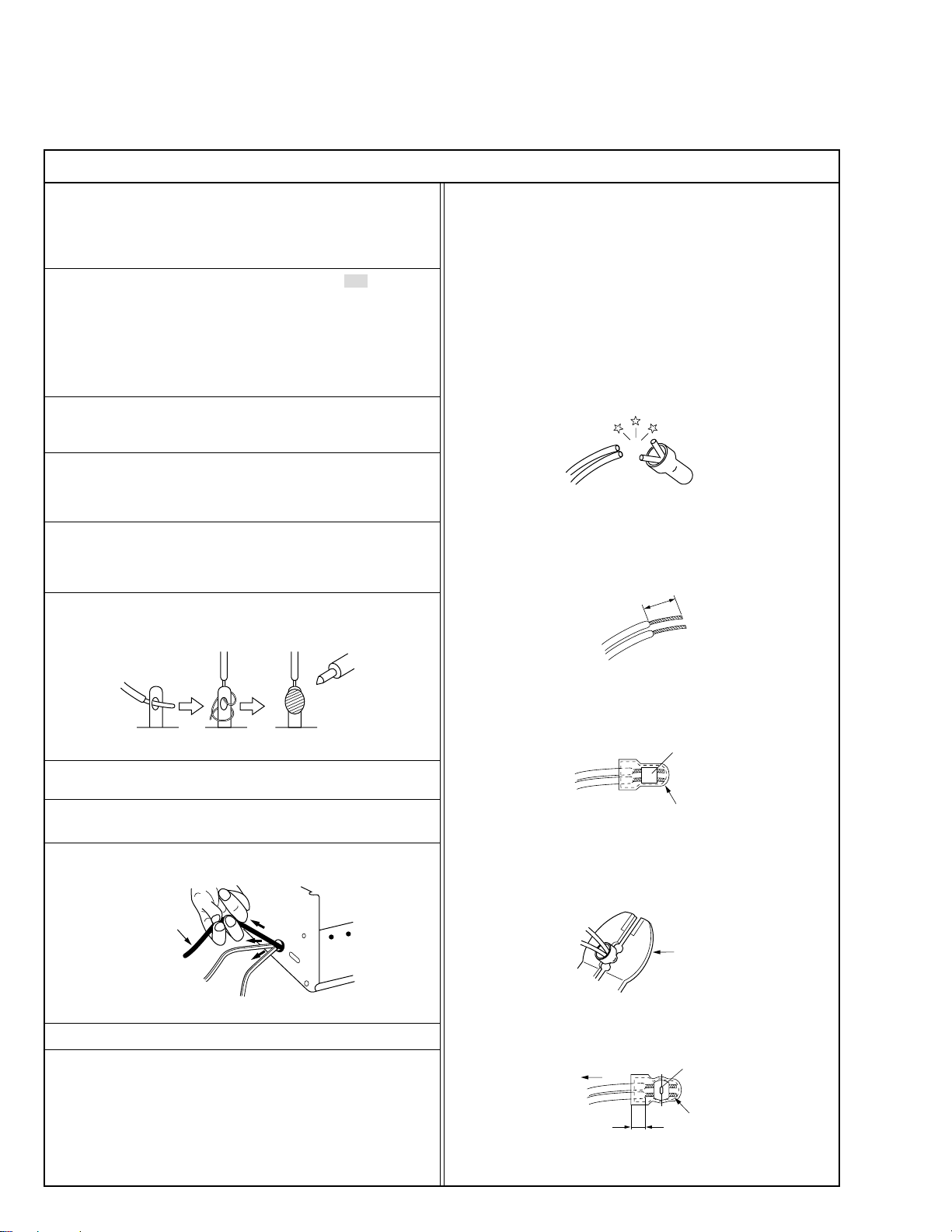
12. Crimp type wire connector
In such cases as when replacing the power transformer in sets
where the connections between the power cord and power transformer primary lead wires are performed using crimp type connectors, if replacing the connectors is unavoidable, in order to prevent
safety hazards, perform carefully and precisely according to the
following steps.
1) Connector part number : E03830-001
2) Required tool : Connector crimping tool of the proper type which
will not damage insulated parts.
3) Replacement procedure
(1) Remove the old connector by cutting the wires at a point
close to the connector.
Important : Do not reuse a connector (discard it).
cut close to connector
Fig.3
(2) Strip about 15 mm of the insulation from the ends of the
wires. If the wires are stranded, twist the strands to avoid
frayed conductors.
15 mm
Fig.1
7. Observe that wires do not contact heat producing parts (heatsinks,
oxide metal film resistors, fusible resistors, etc.)
8. Check that replaced wires do not contact sharp edged or pointed
parts.
9. When a power cord has been replaced, check that 10-15 kg of
force in any direction will not loosen it.
Power cord
Fig.2
10. Also check areas surrounding repaired locations.
11. Products using cathode ray tubes (CRTs)
In regard to such products, the cathode ray tubes themselves, the
high voltage circuits, and related circuits are specified for compliance with recognized codes pertaining to X-ray emission.
Consequently, when servicing these products, replace the cathode ray tubes and other parts with only the specified parts. Under
no circumstances attempt to modify these circuits.
Unauthorized modification can increase the high voltage value and
cause X-ray emission from the cathode ray tube.
Fig.4
(3) Align the lengths of the wires to be connected. Insert the
wires fully into the connector.
Metal sleeve
Connector
Fig.5
(4) As shown in Fig.6, use the crimping tool to crimp the metal
sleeve at the center position. Be sure to crimp fully to the
complete closure of the tool.
1
.2
5
2
.0
5
.5
Fig.6
(5) Check the four points noted in Fig.7.
Not easily pulled free
Wire insulation recessed
more than 4 mm
Fig.7
Crimping tool
Crimped at approx. center
of metal sleeve
Conductors extended
I
S40888-01
Page 4
Safety Check after Servicing
•
Examine the area surrounding the repaired location for damage or deterioration. Observe that screws, parts and wires have been returned
to original positions, Afterwards, perform the following tests and confirm the specified values in order to verify compliance with safety
standards.
1. Insulation resistance test
Confirm the specified insulation resistance or greater between power cord plug prongs and externally exposed parts of the set (RF terminals, antenna terminals, video and audio input and output
terminals, microphone jacks, earphone jacks, etc.). See table 1 below.
2. Dielectric strength test
Confirm specified dielectric strength or greater between power cord plug prongs and exposed accessible parts of the set (RF terminals, antenna terminals, video and audio input and output terminals,
microphone jacks, earphone jacks, etc.). See table 1 below.
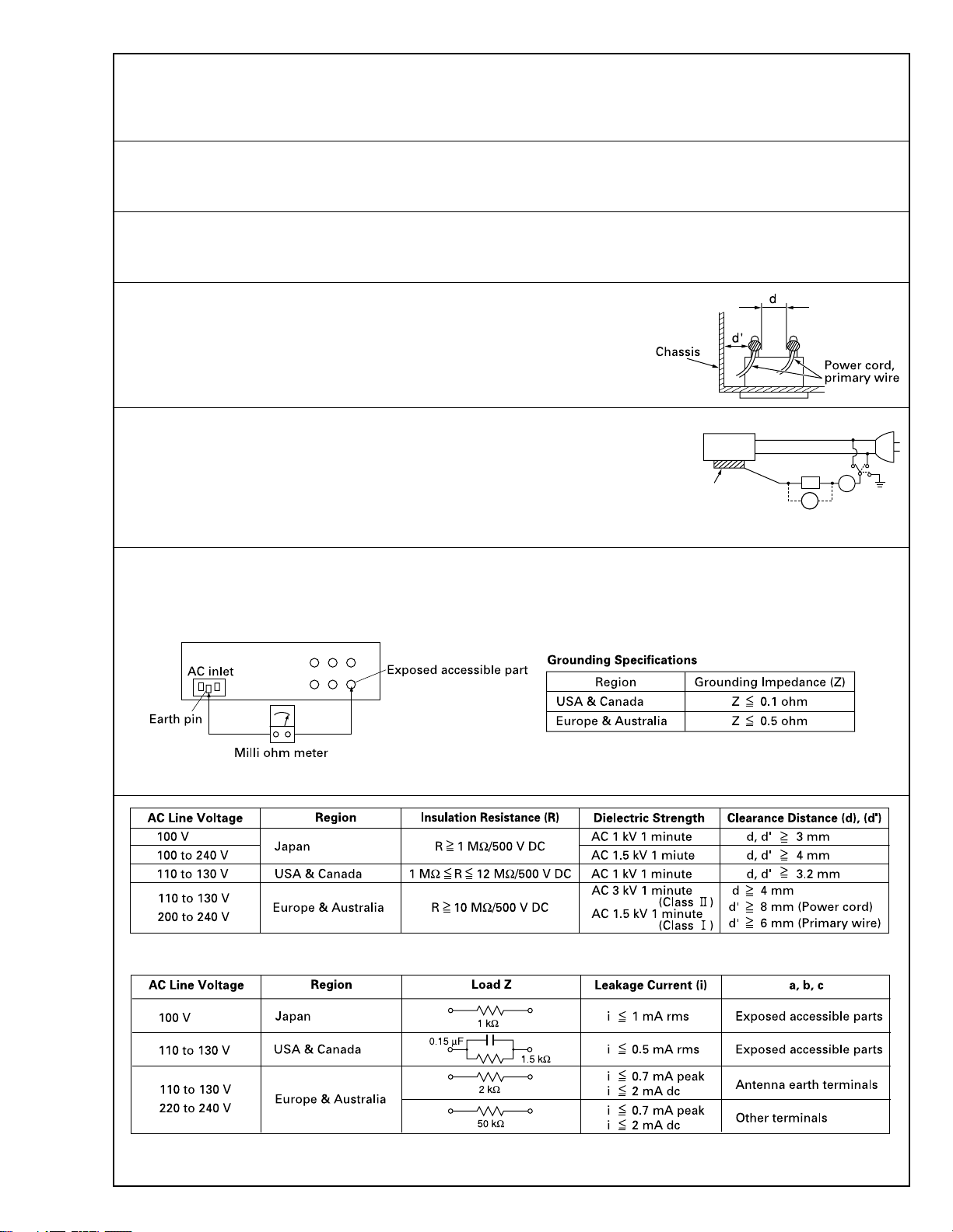
3. Clearance distance
When replacing primary circuit components, confirm specified clearance distance (d), (d’) between soldered terminals, and between terminals and surrounding metallic parts. See table 1
below.
Fig. 8
4. Leakage current test
Confirm specified or lower leakage current between earth ground/power cord plug prongs and
externally exposed accessible parts (RF terminals, antenna terminals, video and audio input and
output terminals, microphone jacks, earphone jacks, etc.).
Measuring Method : (Power ON)
Insert load Z between earth ground/power cord plug prongs and externally exposed accessible
parts. Use an AC voltmeter to measure across both terminals of load Z. See figure 9 and following
table 2.
Externally
exposed
accessible part
Fig. 9
Z
V
ab
A
c
5. Grounding (Class 1 model only)
Confirm specified or lower grounding impedance between earth pin in AC inlet and externally exposed accessible parts (Video in, Video out,
Audio in, Audio out or Fixing screw etc.).
Measuring Method:
Connect milli ohm meter between earth pin in AC inlet and exposed accessible parts. See figure 10 and grounding specifications.
Fig. 10
Table 1 Specifications for each region
Table 2 Leakage current specifications for each region
Note: These tables are unofficial and for reference only. Be sure to confirm the precise values for your particular country and locality.
II
S40888-01
Page 5

Page 6
SECTION 1
DISASSEMBLY
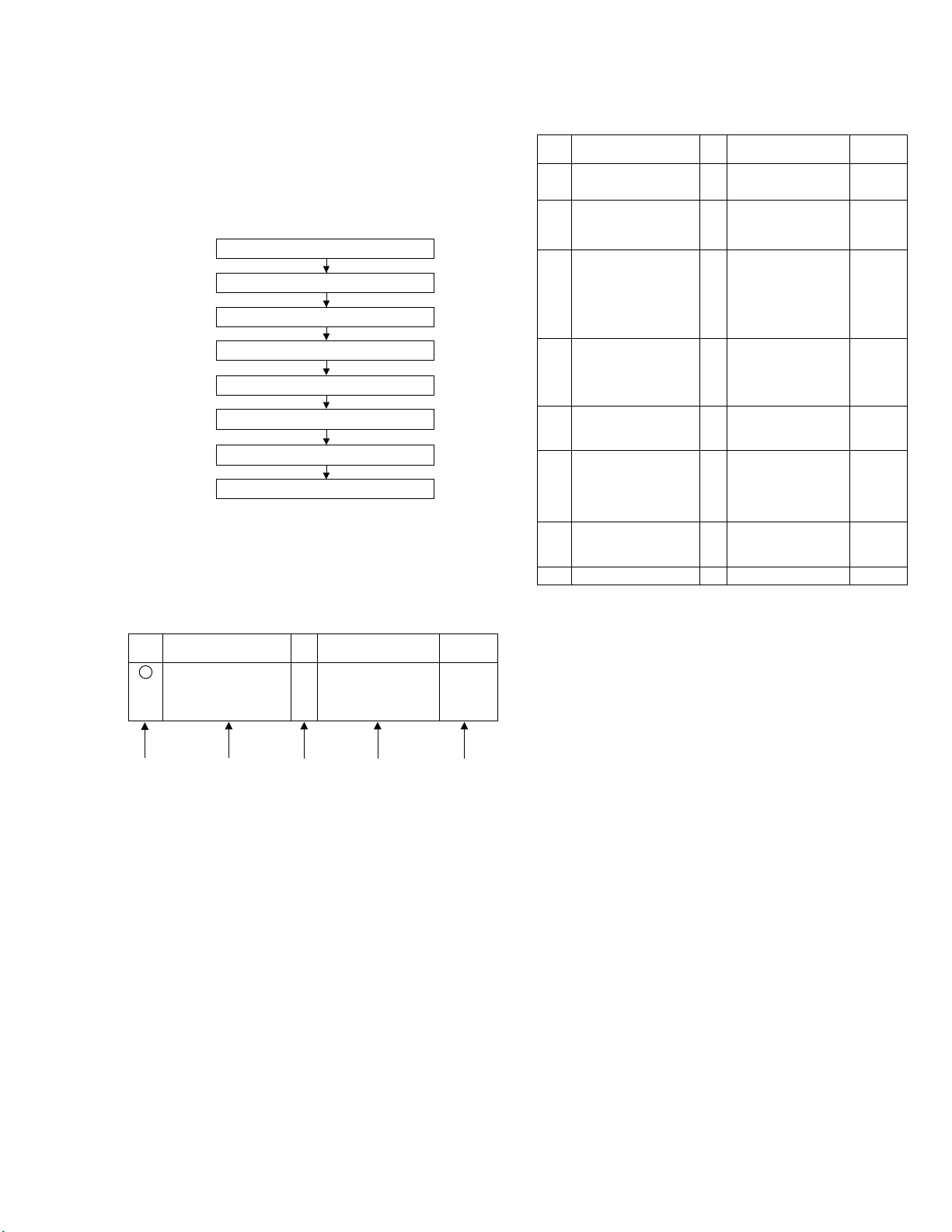
This flowchart lists the disassembling steps for the cabinet
parts and P.C. boards in order to gain access to item(s) to
be serviced. When reassembling, perform the step(s) in reverse order. Bend, route and dress the flat cables as they
were originally laid.
1
2
3
4
5
6
7
8
1.2
HOW TO READ THE DISASSEMBLY AND ASSEMBLY
<Example>
Step/
Loc No.
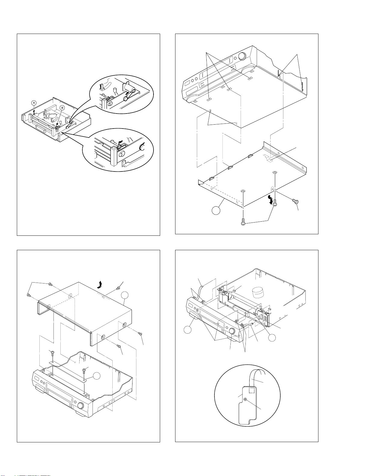
1 Top cover, D1
(1) (2) (3) (4) (5)
(1) Order of steps in Procedure
When reassembling, perform the step(s) in the reverse order.
These numbers are also used as the identification (location) No.
of parts Figures.
(2) Part name to be removed or installed.
(3) Fig. No. showing procedure or part location.
(4) Identification of part to be removed, unhooked, unlocked,
released, unplugged, unclamped or unsoldered.
P= Spring, W= Washer, S= Screw, L= Locking tab, SD= Solder,
CN**(WR**)= Remove the wire (WR**) from the connector
(CN**).
Note:
• The bracketed ( ) WR of the connector symbol are as-
signed nos. in priority order and do not correspond to
those on the spare parts list.
(5) Adjustment information for installation
Part Name
Bracket 2(S1c)
Top cover, Bracket
Bottom cover
Front panel assembly
Drum assembly
Mechanism assembly
SW/Display board assembly
P/S Converter board assembly
Main board assembly
Fig.
No.
Point Note
4(S1a),(S1b),3(L1a), <Note 1>
2(SD1a),(P1a),
CN1(WR1a),
1.3 DISASSEMBLY/ASSEMBLY METHOD1.1 DISASSEMBLY FLOW CHART
Step/
Loc No.
1
2
3
4
5
6
7
8
<Note 2>
• When attaching the Bottom cover, make sure that the Earth
plate of the Bottom cover is passed through the hole of the
Bottom chassis and then touches the GND (Ground) on the
Main board assembly.
<Note 3a>
• Be careful not to damage the connector and wire etc. during
connection and disconnection.
When connecting the wire to the connector, be careful with the
wire direction.
<Note 3b>
• When reattaching the Front panel assembly, make sure that
the door opener
in position prior to the reinstallation.
<Note 5a>
• When it is required to remove the screws (S5a) retaining the
Mechanism assembly, please refer to the “Procedures for Lowering the Cassette holder assembly”(See on pages 1-2).
• When removing the Mechanism assembly only, unhook the two
spacers connecting it with the Main board assembly with pliers
from the back side of the Main board assembly first, and then
remove the Mechanism assembly.
• When reattaching the Mechanism assembly to the Main board
assembly, take care not to damage the sensors on the Main
board assembly (D3001: LED, Q3002: Start sensor, Q3003:
End sensor, S3002 : S cassette switch).
<Note 5b>
• The wire (WR5) has excess length that may be loose, as it is
quite long. After inserting the wire and connectors, the loose
portion of the wire should be taken up and accommodated between the A/C head base and the main deck.
<Note 6>
• The REC safety board assembly is attached to the SW/Display
board assembly. It is therefore necessary to remove the REC
safety board assembly before removing the SW/Display board
assembly.
Part Name
Top cover, D1 4(S1a), (S1b)
Bracket 2(S1c)
Bottom cover D2 4(L2a),3(L2b),(S2a), <Note 2>
Front panel assembly D3
Drum assembly D4
(Inertia plate) 4(L4a)
(Roller arm assy) (P4), (L4b)
Mechanism assembly D5 2(S5a),(S5b),(S5c),
SW/Display board D6 CN7001(WR6a),
assembly CN7191(WR6b),
P/S Converter board D7 2(S7),
assembly CN3501(WR7a),
Main board assembly D8 2(S8), (L8)
a of the Cassette holder assembly is lowered
Fig.
No.
Point Note
------------------
2(S2b)
------------------
Earth plate
7(L3),CN901(WR3a),
CN7002(WR3b)
[HR-S6700MS]
CN3012(WR3b)
[HR-S7700MS]
------------------
2(S3),Jack board assy
3(S4),CON1(WR4a),
CN1(WR4b)
------------------
------------------
2(L5), CN1(WR5)
(L6a),
REC safety board assy,
2(L6b), 5(L6c)
CN3502(WR7b)
<Note 3a>
<Note 3b>
<Note 3a>
<Note 3a>
<Note 5a>
<Note 5b>
<Note 3a>
<Note 6>
<Note 3a>
1-1
Page 7
Procedures for Lowering the Cassette holder assembly
As the mechanism of this unit is integrated with the Housing
assembly, the holder must be lowered and the two screws unscrewed when removing the Mechanism assembly.
Fig. 2
(L2b)
(L2a)
(L2a)
Fig. 1
Fig. 3
Turn the loading motor pulley in the direction as indicated by
Fig.2. As both
and ı levers are lodged twice, push the
Å
levers in the direction as indicated by Fig.3 to release them.
When pushing the levers, do it in the order of
Å, ı, ı, Å
When the holder has been lowered, turn the pulley until the
cassette holder is securely in place without allowing any up/
down movement.
Procedures for Lowering the Cassette holder assembly
(S1a)
(S1b)
1
Top cover
Earth plate
<Note 2>
.
2
(S2a)
(S2b)
Fig. D2
WR3a
Foil side
<Note 3a>
(L3)
CN901
CN3012
[HR-S7700MS]
1-2
(S1c)
3
(S1a)
(S1a)
(S1c)
1
Bracket
(L3)
Jog shuttle
Front panel
back side
Jack board
assembly
(L3)
CN7192
Fig. D1 Fig. D3
WR3b
Foil side
<Note 3a>
WR3a
(S3)
CN7002
[HR-S6700MS]
a <Note 3b>
Page 8
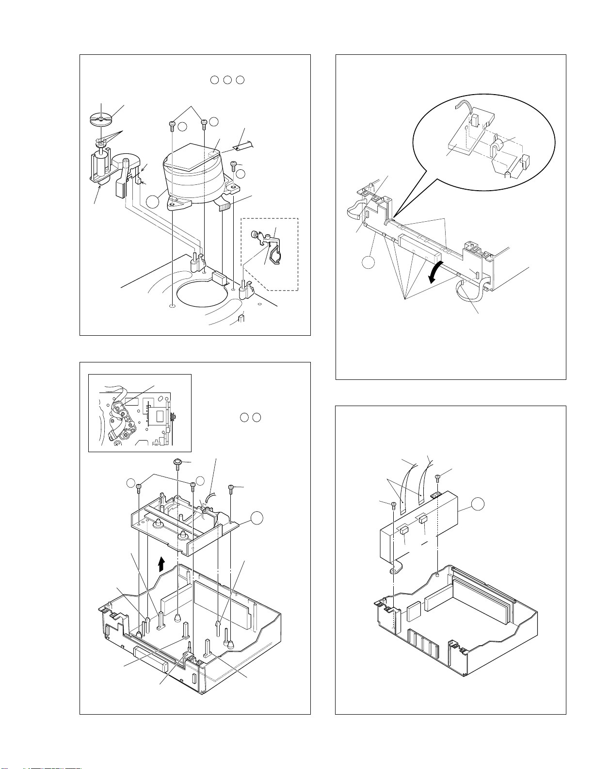
Note: When installing the Drum assembly, secure the
(L6c)
CN7001
(L6b)
6
CN7191
(L6a)
REC Safety
board assembly
<Note 6>
WR6b
Foil side
<Note 3a>
WR6a
Supporting
tape side
<Note 3a>
screws (S4) in the order of a , b , c .
Roller arm
assy
WR5
Inertia plate
(L4a)
(P4)
(L4b)
4
A/C head base
(S4)
a
c
CON1
WR4a
Foil side
<Note 3a>
(S4)
b
CN1
Fig. D4
Note:
When installing the
Mechanism assembly,
secure the screws (S5a) in
the order of a , b .
WR4b
Foil side
<Note 3a>
Cleaner assy
(L4c)
Not use
Fig. D6
Q3003
End sensor
<Note 5a>
(L5)
Spacer
<Note 5a>
D3001
LED
<Note 5a>
(S5a)
<Note 5a>
b
S3002
S cassette switch
<Note 5a>
Fig. D5
(S5b)
a
CN1
WR5
Foil side
<Note3a>
<Note 5b>
(S5c)
5
(L5)
Spacer
<Note 5a>
Q3002
Start sensor
<Note 5a>
Foil side
<Note 3a>
(S7)
WR7a
CN3501
WR7b
(S7)
7
CN3502
Fig. D7
1-3
Page 9
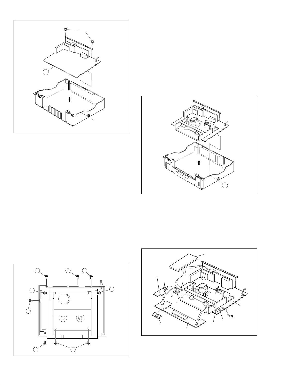
(S8)
8
(L8)
Fig. D8
1.4 SERVICE POSITION
In order to facilitate diagnosis and the repair of the Mechanism assembly, this unit is constructed so as to allow the
Mechanism and Main board assemblies to be removed together from the Bottom chassis assembly.
1.4.1 How to take out the Mechanism and Main board
assemblies
(1) Remove the Top cover, Bracket, Front panel assembly
and Jack board assembly. (Refer to 1.3 DISASSEMBLY/
ASSEMBLY METHOD. )
(2) Lower the cassette holder, and make the preparations re-
quired in order to remove the screws from the Mechanism assembly. (Refer to the “Procedures for Lowering
the Cassette holder assembly” on pages 1-2 of 1.3 DISASSEMBLY/ASSEMBLY METHOD.)
(3) Take out 2 screws
, 1 screw ı and 1 screw Ç as
Å
shown in Fig. 1-4-1.
(4) Remove the flat wires from CN3011 and CN902 on the
Main board assembly.
ED
D
(5) Take out 2 screws
and 1 screw ´ as shown in Fig. 1-
Î
4-1.
(6) Take out 2 screws
as shown in Fig. 1-4-1. Then re-
Ï
move the P/S Converter board assembly. (Refer to 1.3
DISASSEMBLY/ASSEMBLY METHOD.)
(7) Remove the hook
while holding the edge of the Main
˝
board assembly, and remove the Main board and Mechanism assemblies together. At this stage be careful of the
power cord and prongs of the jacks on the back side. (Refer to Fig. 1-4-2.)
(8) Remove the SW/Display board assembly and REC safety
board assembly. (Refer to page 1-3 of 1.3 DISASSEMBLY/ASSEMBLY METHOD. Take care not to pull the flat
wires (Fig. D7) from CN7001 and CN7191.)
G
Fig. 1-4-2
(9) Place the SW/Display board assembly, REC safety board
assembly, Jack board assembly and P/S Converter board
assembly on the front side and left side of the Mechanism and Main board assemblies which was removed at
the step (7), then connect the flat wires into CN3011,
CN901 and CN902 of the Main board assembly, CN3501
and CN3502 of the P/S Converter board assembly. (Refer to Fig. 1-4-3.)
P/S Converter board Assembly
CN3502
CN3501
Jack board
Assembly
CN7192
CN6102
1-4
B
F
C
CN901
REC safety board
Assembly
CN902
CN3011
SW/Disply board Assembly
CN3012
Main board
Assembly
To Jog
Fig. 1-4-3
(10)
AF
Fig. 1-4-1
Connect the power cord to the wall socket, and lift the
cassette holder.
(Before turning on the power make sure that there is nothing which may produce a short circuit, such as faulty soldering.)
Page 10
Note:
• When carrying out diagnosis and repair of the Main
board assembly in the service position, be sure to
ground both the Main board and the Mechanism assemblies.
If they are improperly grounded, there may be noise
on the playback picture or the FDP counter display may
move even when the mechanism is kept in an inoperative status.
• In the "SERVICE POSITION", the cassette tabs cannot
be detected and recording becomes possible even with
a cassette with broken tabs such as the alignment tape.
Be very careful not to erase important tapes.
(5) The switch on the REC safety board assembly does not
have to be operated when ejecting a tape. But be sure
to turn the set to the normal position before ejecting the
tape.
1.4.2 Precautions for cassette loading in the "SERVICE
POSITION"
The REC safety board assembly detects cassette loading as
well as cassette tabs. Therefore, after the assembly has been
removed in the "SERVICE POSITION", it is required to set
the switch manually on the REC safety board assembly when
a cassette is loaded.
1.4.3 Cassette loading and ejection methods in the
“SERVICE POSITION”(See Fig. 1-4-3).
(1)
Insert a cassette halfway in the Cassette holder assembly.
(2) Set the switch on the REC safety board assembly to ON
(by pressing the switch).
(3) As soon as the cassette starts to be loaded, set the switch
on the REC safety board assembly to OFF (by releasing
the switch).
(4) Now the desired operation (recording, playback, fast for-
ward, rewind, etc.) is possible in this status (the status
shown in Fig.1-4-3).
Notes:
• When performing diagnostics of the tape playback or
the recording condition in the "SERVICE POSITION",
enter the desired mode before turning the set upside
down, and do not change the mode when performing
diagnostics while the set is placed upside down. If you
want to switch the mode, turn the set to the normal position (the status shown in Fig.1-4-3).
1.5 MECHANISM SERVICE MODE
This model has a unique function to enter the mechanism
into every operation mode without loading of any cassette
tape. This function is called the “MECHANISM SERVICE
MODE”.
1.5.1 How to set the "MECHANISM SERVICE MODE"
(1) Disconnect VCR from AC.
(2) Connect TPGND and TP7001 (TEST) on the SW/Display
board assembly with a jump wire.
(3) Connect VCR to AC.
(4) Press the POWER button.
(5) With lock levers
on the left and right of the Cassette
Åı
holder assembly pulled toward the front, slide the holder
in the same direction as the cassette insertion direction.
(For the positions of lock levers
, refer to the “Pro-
Åı
cedures for Lowering the Cassette holder assembly” on
pages 1-2 of 1.3 DISASSEMBLY/ASSEMBLY METHOD.)
(6) The cassette holder lowers and, when the loading has
completed, the mechanism enters the desired mode.
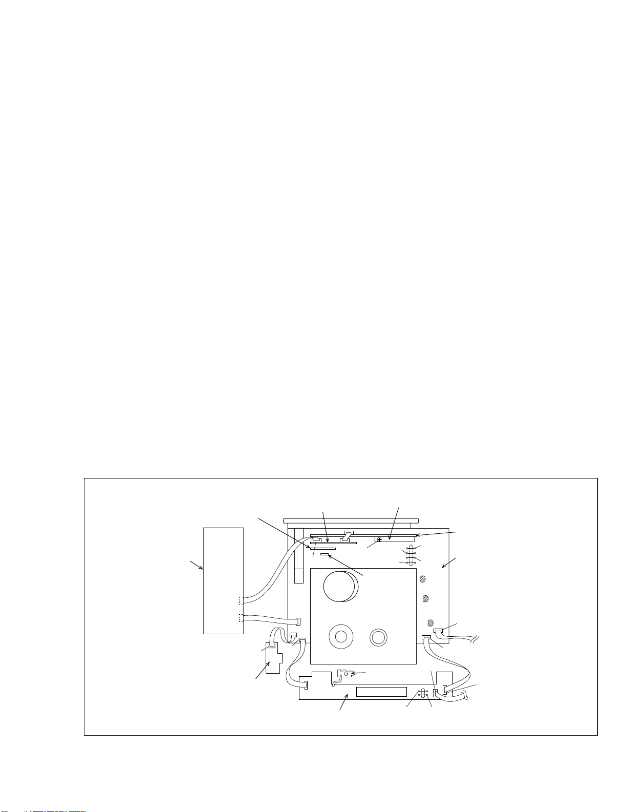
P/S Converter board
assembly
DEMOD board assembly
CN3502
CN3501
CN7192
Jack board assembly
S-Sub board assembly
CN513
CN6102
CN901
CN902
CN7191
SW/Display board assembly
Fig. 1-5-1
2D Digital [HR-S6700MS] or
3D Digital/2M [HR-S7700MS] board assembly
VR1401
D/A LEVEL ADJ
[HR-S7700MS]
Audio erase
board assembly
REC safety board
assembly
TP4001
CTL.P
TP2253
A.FM
TP7001 (TEST)
TP111
D.FF
TP106
PB.FM
CP4001
CP5302
CP5301
CN7002
[HR-S6700MS]
TPGND
Terminal board assembly
Main board assembly
[HR-S7700MS]
CN3012
CN3011
To Jog [HR-S7700MS]
CN7001
To Shuttle play [HR-S6700MS]
1-5
Page 11
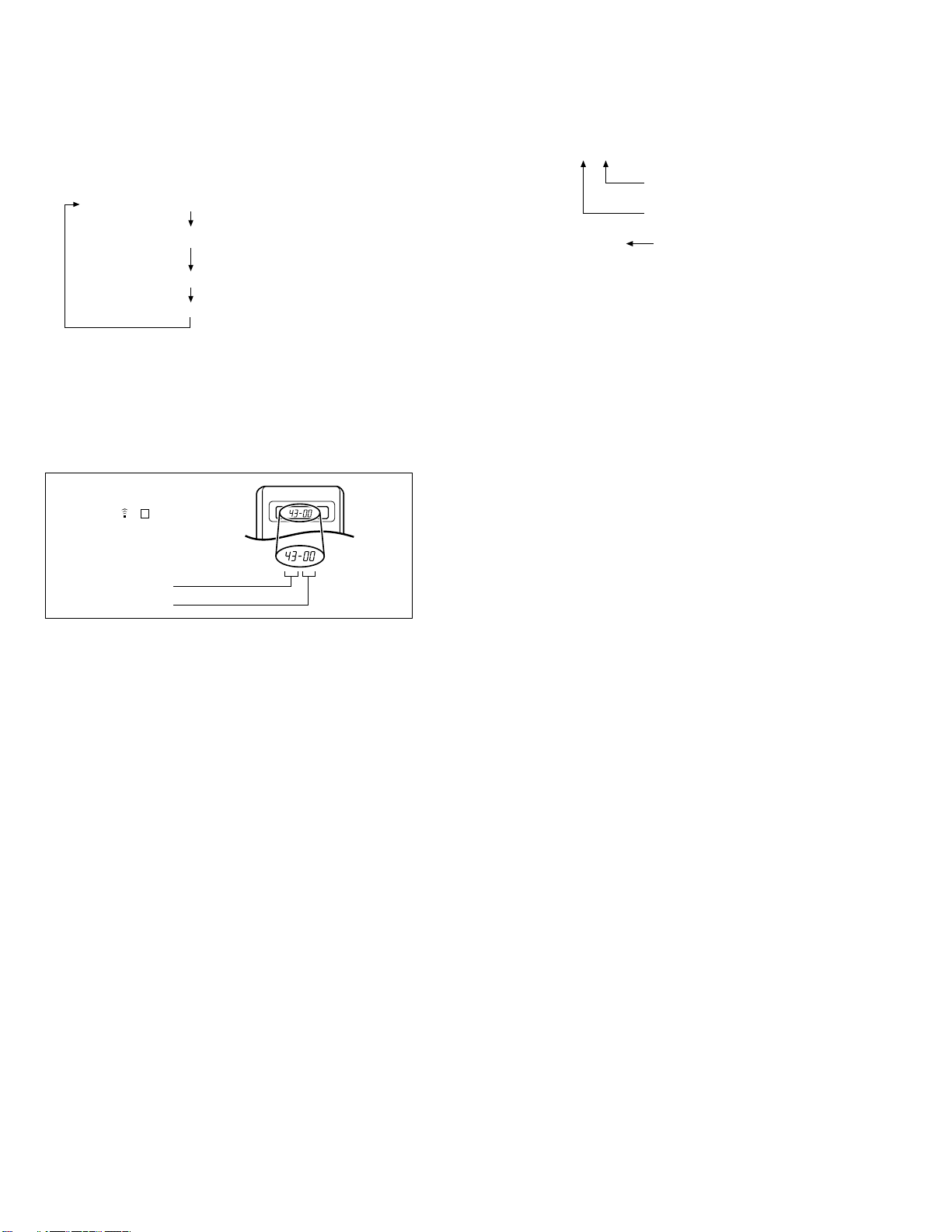
1.6 EMERGENCY DISPLAY FUNCTION
This unit has a function for storing the history of the past two
emergencies (EMG) and displaying them on each FDP. With the
status of the VCR and mechanism at the moment an emergency
occurred can also be confirmed.
1.6.1 Displaying the emergency information
(1) Transmit the code “59” from the Jig RCU.
The FDP shows the emergency content in the form of
“E:
:**”.
**
Example 1 E : 01 :
03
FDP display switching
FDP display
Notes:
• The emergency detail display
on the latest emergency.
It becomes “ – – : – – : – –” when there is no latest emergency record.
• When using the Jig RCU, set its custom code to match
the custom code of the VCR.
Jig RCU
[Data transmitting method]
Depress the “ ” ( 3 ) button
after the data code is set.
0 : 00 : 00
E: **:
1: *2 :
*
5: *6 :
*
CUSTOM CODE
43: A CODE
53: B CODE
DATA CODE
Fig. 1-6-1 Jig RCU [PTU94023B]
Normal display
Emergency content display
**
(E:Latest:Previous)
Emergency detail display
34
Emergency detail display
7
*
show the information
1 2
1
2
INITIAL MODE
Previous emergency
Latest emergency
––
Example 2 E : –– :
Note:
• For the emergency content, see “1.6.3 Emergency content description”.
(2) Transmit the code “59” from the Jig RCU again.
The FDP shows the emergency detail information 1 in the
form of “
*
*
3 – : Mechanism sensor information at the moment of
– 4 : Mechanism mode position at the moment of emer-
Note:
• For the emergency detail information 1 , see “1.6.4 Emergency detail information
(3) Transmit the code “59” from the Jig RCU once again.
The FDP shows the emergency detail information
form of “
*
*
*
Note:
• For the emergency detail information
gency detail information
1 : *2 : 34”.
*
1 : Deck operation mode at the moment of emergency
2 : Mechanism operation mode at the moment of emer-
gency
emergency
gency
5 : *6 :
*
5 : Type of the cassette tape in use
7 ”.
*
6 : Winding position of the cassette tape in use
7 : Type of the cassette tape in use
No emergency record
1
”.
2
”.
2
in the
2
.
1
(Winding area)
2
, see “1.6.5 Emer-
(4) Transmit the code “59” from the Jig RCU once again to re-
set the display.
1.6.2 Clearing the emergency history
(1) Display the emergency history.
(2) Transmit the code “36” from the Jig RCU.
(3) Reset the emergency display.
(Y292-03e)
1-6
Page 12

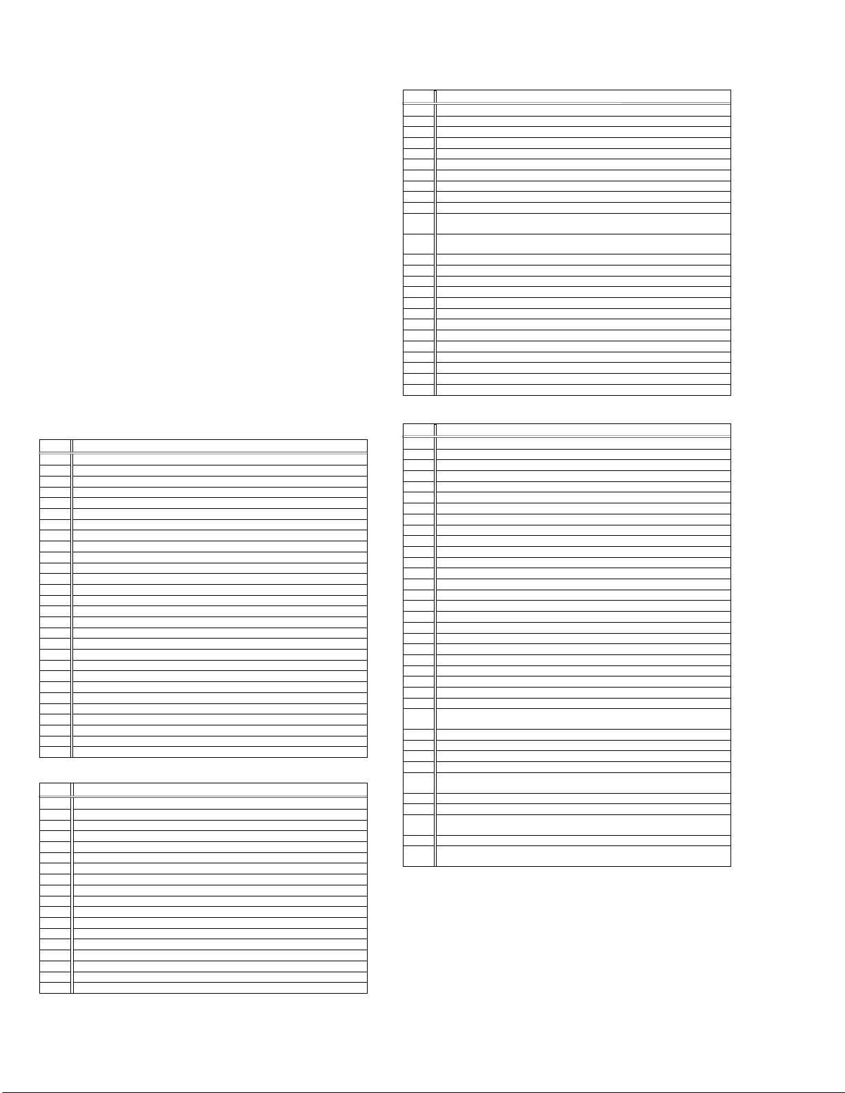
1.6.3 Emergency content description
Note:
Emergency contents “E08/E09” are for the model with Dynamic Drum (DD).
FDP CONTENT CAUSE
E01: Loading EMG
E02:
Unloading EMG
E03: Take Up Reel
Pulse EMG
E04: Drum FG
EMG
E05: Cassette Eject
EMG
E06: Capstan FG
EMG
E07: SW Power
Short-Circuit
EMG
E08:
DD Initialized
(Absolute
Position
Sensor)
EMG
E09: DD FG EMG
E0A:Supply Reel
Pulse EMG
EC1 or EU1:
Head clog warning
When the mechanism mode cannot be changed to another mode even when the loading motor has rotated
for more than 4 seconds in the loading direction, [E:01]
is identified and the power is turned off.
When the mechanism mode cannot be changed to another mode even when the loading motor has rotated
for more than 4 seconds in the unloading direction, [E:02]
is identified and the power is turned off.
When the take-up reel pulse has not been generated for
more than 4 seconds in the capstan rotating mode, [E:03]
is identified, the pinch rollers are turned off and stopped,
and the power is turned off. However, the reel EMG is
not detected in STILL/SLOW modes.
When the drum FG pulse has not been input for more
than 3 seconds in the drum rotating mode, [E:04] is identified, the pinch rollers are turned off and stopped, and
the power is turned off.
When the eject operation does not complete in 3 seconds after the start, [E:05] is identified, the pinch rollers
are turned off and stopped, and the power is turned off.
When the cassette insertion operation does not complete
in 3 seconds after the start, the cassette is ejected. In
addition, when the operation does not complete within
3 seconds after the start, [E:05] is also identified and the
power is turned off immediately.
When the capstan FG pulse has not been generated for
more than 1 second in the capstan rotating mode, [E:06]
is identified, the pinch rollers are turned off and stopped,
and the power is turned off.However, the capstan EMG
is not detected in STILL/SLOW/FF/REW modes.
When short-circuiting of the SW power supply with GND
has lasted for 0.5 second or more, [E:07] is identified,
all the motors are stopped and the power is turned off.
When DD tilting does not complete in 4 seconds, [E:08]
is identified, the tilt motor is stopped and the power is
turned off.
When the DD FG pulse is not generated within 2.5 seconds, [E:09] is identified, the tilt motor is stopped and
the power is turned off.
When the supply reel pulse has not been generated for
more than 10 seconds in the capstan rotating mode,
[E:0A] is identified and the cassette is ejected (but the
power is not turned off). However, note that the reel EMG
is not detected in the SLOW/STILL mode.
Presupposing the presence of the control pulse output in the PLAY mode, when the value obtained by mixing the two V.FM output
channels (without regard to the A.FM output) has remained below a certain threshold level for more than 10 seconds, [E:C1] or [E:U1]
is identified and recorded in the emergency history. During the period in which a head clog is detected, the FDP and OSD repeat the
“3-second warning display” and “7-second noise picture display” alternately.
EMG code : “E:C1” or “E:U1” / FDP : “U:01” / OSD : “Try cleaning tape.” or “Use cleaning cassette.”
The head clog warning is reset when the above-mentioned threshold has been exceeded for more than 2 seconds or the mode is
changed to another mode than PLAY.
1
The mechanism is locked in the middle of mode transition.
2
The mechanism is locked at the loading end due to the encoder position
reading error during mode transition.
3
Power is not supplied to the loading MDA.
1
The mechanism is locked in the middle of mode transition.
2
The mechanism is locked at the unloading end due to the encoder position reading error during mode transition.
3
Power is not supplied to the loading MDA.
1
The take-up reel pulse is not generated in the FWD transport modes (PLAY/
FWD SEARCH/FF, etc.) because;
1) The idler gear is not meshed with the take-up reel gear;
2)
The idler gear is meshed with the take-up reel gear, but incapable of winding due to too large mechanical load (abnormal tension);
3) The take-up reel sensor does not output the FG pulse.
2
The supply reel pulse is not generated in the REV transport modes (REV
SEARCH/REW, etc.) because;
1) The idler gear is not meshed with the supply reel gear.
2) The idler gear is meshed with the supply reel gear, but incapable of winding due to too large a mechanical load (abnormal tension);
3) The supply reel sensor does not output the FG pulse.
3
Power is not supplied to the reel sensors.
1
The drum could not start or the drum rotation has stopped due to too large
a load on the tape, because;
1) The tape tension is abnormally high;
2)
The tape is damaged or a foreign object (grease, etc.) adheres to the tape.
2
The drum FG pulse did not reach the System controller CPU because;
1) The signal circuit is disconnected in the middle;
2) The FG pulse generator (hall device) of the drum is faulty.
3
The drum control voltage (DRUM CTL V) is not supplied to the MDA.
4
Power is not supplied to the drum MDA.
1
The cassette cannot be ejected due to a failure in the drive mechanism of
the housing.
2
When the housing load increases during ejection, the loading motor is
stopped because of lack of headroom in its drive torque.
Housing load increasing factors: Temperature environment (low temperature, etc.), mechanism wear or failure.
3
The sensor/switch for detecting the end of ejection are not functioning normally.
4
The loading motor drive voltage is lower than specified or power is not supplied to the motor (MDA).
5
When the user attempted to eject a cassette, a foreign object (or perhaps
the user's hand) was caught in the opening of the housing.
1
The capstan could not start or the capstan rotation has stopped due to too
large a load on the tape, because;
1) The tape tension is abnormally high (mechanical lock);
2) The tape is damaged or a foreign object (grease, etc.) is adhered to the
tape (occurrence of tape entangling, etc.).
2
The capstan FG pulse did not reach the System controller CPU because;
1) The signal circuit is disconnected in the middle;
2) The FG pulse generator (MR device) of the capstans is faulty.
3
The capstan control voltage (CAPSTAN CTL V) is not supplied to the MDA.
4
Power is not supplied to the capstan MDA.
1
The SW 5 V power supply circuit is shorted with GND.
2
The SW 12 V power supply circuit is shorted with GND.
1 The absolute value sensor is defective. (The soldered parts have separated.)
2 The pull-up resistor at the absolute sensor output is defective. (The soldered parts
have separated.)
3 Contact failure or soldering failure of the pins of the connector (board-to-board) to the
absolute value sensor.
4
The absolute value sensor data is not sent to the System Controller CPU.
1 The FG sensor is defective. (The soldered parts have separated.)
2 The pull-up resistor at the FG sensor output is defective. (The soldered parts have
separated.)
3 Contact failure or soldering failure of the pins of the connector (board-to-board) to the FG sensor.
4 The power to the sensor is not supplied. (Connection failure/soldering failure)
5 The FG pulse is not sent to the System Controller CPU.
6
The tilt motor is defective. (The soldered parts have separated.)
7 The drive power to the tilt motor is not supplied. (Connection failure/soldering failure)
8 The tilt motor drive MDA - IC is defective.
9 Auto-recovery of the DD tilting cannot take place due to overrun.
1
The supply reel pulse is not generated in the FWD transport mode (PLAY/
FWD SEARCH/FF, etc.) because;
1) PLAY/FWD or SEARCH/FF is started while the tape in the inserted cas-
sette is cut in the middle;
2) A mechanical factor caused tape slack inside and outside the supply
reel side of the cassette shell. In this case, the supply reel will not rotate
until the tape slack is removed by the FWD transport, so the pulse is not
generated until then;
3) The FG pulse output from the supply reel sensor is absent.
2
The take-up reel pulse is not generated in the REV transport mode (REV
SEARCH/REW, etc.).
1) REV SEARCH/REW is started when the tape in the inserted cassette
has been cut in the middle;
2) A mechanical factor caused tape slack inside and outside the take-up
reel side of the cassette shell. In this case, the supply reel will not rotate
until the tape slack is removed by the REV transport, so the pulse will
not be generated until that time;
3) The FG pulse output from the take-up reel sensor is absent.
3
The power to a reel sensor is not supplied.
Table 1-6-1
1-7
Page 13
1.6.4 Emergency detail information
1
The status (electrical operation mode) of the VCR and the status (mechanism operation mode/sensor information) of the
mechanism in the latest emergency can be confirmed based on
the figure in EMG detail information
.
1
[FDP display]
1 : *2 : 34
*
1 : Deck operation mode at the moment of emergency
*
2 :
Mechanism operation mode at the moment of emergency
*
3 – :
Mechanism sensor information at the moment of emergency
– 4 :
Mechanism mode position at the moment of emergency
Note:
• In the Deck operation mode/Mechanism operation mode/
Mechanism mode position, the contents of the code that
is shown on the FDP differs depending on the parts
number of the System Control microprocessor (IC3001)
of the VCR.
For the microprocessor parts number that starts with the
two letters “MN”, refer to the Table of MN and for parts
number with “HD”, refer to the Table of HD.
2 : Mechanism Operation Mode
*
[Table of MN]
Display
00 Command standby (Status without executing command)
02 POWER OFF by EMG occurrence
04 Moving to the adjacent position in the LOAD direction
06 Moving to the adjacent position in the UNLOAD direction
08 Cassette ejection being executed
0A Cassette insertion being executed
0C Tape being loaded
0E Tape being unloaded
10 Mode transition to STOP with pinch roller compression ON
12 Mode transition to STOP with pinch roller compression OFF
14 Mode transition to STOP with pinch roller compression OFF as a result
of POWER OFF
16 Mode transition to STOP with pinch roller compression ON as a result of
POWER ON
18 Mode transition to PLAY
1A Mode transition to FWD SEARCH
1C Mode transition to REC
1E Mode transition to FWD STILL/SLOW
20 Mode transition to REV STILL/SLOW
22 Mode transition to REV SEARCH
24 Mode transition from FF/REW to STOP
26 Mode transition to FF
28 Mode transition to REW
2A 4 sec. of REV as a result of END sensor going ON during loading
2C Short FF/REV as a result of tape sensor going ON during unloading
2E Mechanism position being corrected due to overrun
80 Mechanism in initial position (Dummy command)
Mechanism Operation Mode
1 : Deck Operation Mode
*
[Table of MN]
Display
00 Mechanism being initialized
01 STOP with pinch roller pressure off (or tape present with P.OFF)
02 STOP with pinch roller pressure on
03 POWER OFF as a result of EMG
04 PLAY
0C REC
10 Cassette ejected
20 FF
21 Tape fully loaded, START sensor ON, short FF
22
Cassette identification FWD SEARCH before transition to FF (SP x7-speed)
24 FWD SEARCH (variable speed) including x2-speed
2C INSERT REC
40 REW
42
Cassette identification REV SEARCH before transition to REW (SP x7-speed)
44 REV SEARCH (variable speed)
4C AUDIO DUB
6C INSERT REC (VIDEO + AUDIO)
84 FWD STILL/SLOW
85 REV STILL/SLOW
8C REC PAUSE
8D Back spacing
8E Forward spacing (FWD transport mode with BEST function)
AC INSERT REC PAUSE
AD INSERT REC Back spacing
CC AUDIO DUB PAUSE
CD AUDIO DUB Back spacing
EC INSERT REC (VIDEO + AUDIO) PAUSE
ED INSERT REC (VIDEO + AUDIO) Back spacing
Deck Operation Mode
[Table of HD]
Display
00 STOP with pinch roller pressure off (or tape present with P.OFF)
01 STOP with pinch roller pressure on
04 PLAY
0E REC
11 Cassette ejected
22 FF
26 FWD SEARCH (variable speed) including x2-speed
2E INSERT REC
43 REW
47 REV SEARCH (variable speed)
4C AUDIO DUB
6E INSERT REC (VIDEO+AUDIO)
84 FWD STILL/SLOW
85 REV STILL/SLOW
8F REC PAUSE
AF INSERT REC PAUSE
CD AUDIO DUB PAUSE
EF INSERT REC (VIDEO+AUDIO) PAUSE
Deck Operation Mode
[Table of HD]
Display
00 STOP with pinch roller pressure off
01 STOP with pinch roller pressure on
02 U/L STOP (or tape being loaded)
04 PLAY
05 PLAY (x1-speed playback using JOG)
0E REC
11 Cassette ejected
22 FF
26 FWD SEARCH (variable speed) including x2-speed
2E INSERT REC
43 REW
47 REV SEARCH
4C AUDIO DUB
6E INSERT REC (VIDEO + AUDIO)
84 FWD STILL/SLOW
85 REV STILL/SLOW
8F REC PAUSE
AF INSERT REC PAUSE
C7 REV SEARCH (x1-speed reverse playback using JOG)
CD AUDIO DUB PAUSE
EF INSERT REC (VIDEO + AUDIO) PAUSE
F0 Mechanism being initialized
F1 POWER OFF as a result of EMG
F2 Cassette being inserted
F3 Cassette being ejected
F4 Transition from STOP with pinch roller pressure on to STOP with pinch
roller pressure off
F5 Transition from STOP with pinch roller pressure on to PLAY
F6 Transition from STOP with pinch roller pressure on to REC
F7 Cassette type detection SEARCH before FF/REW is being executed
F8 Tape being unloaded
F9 Transition from STOP with pinch roller pressure off to STOP with pinch
roller pressure on
FA Transition from STOP with pinch roller pressure off to FF/REW
FB Transition from STOP with pinch roller pressure off to REC.P (T.REC,etc.)
FC Transition from STOP with pinch roller pressure off to cassette type de-
tection SEARCH
FD Short REV being executed after END sensor on during unloading
FE Tension loosening being executed after tape loading (STOP with pinch
roller pressure on)
Mechanism Operation Mode
1-8
Page 14

3 – : Mechanism Sensor Information
[Common table of MN and HD]
Display
0– VHS Tab broken ON ON
1– VHS Tab broken ON OFF
2– VHS Tab broken OFF ON
3– VHS Tab broken OFF OFF
4– VHS Tab present ON ON
5– VHS Tab present ON OFF
6– VHS Tab present OFF ON
7– VHS Tab present OFF OFF
8– S-VHS Tab broken ON ON
9– S-VHS Tab broken ON OFF
A– S-VHS Tab broken OFF ON
B– S-VHS Tab broken OFF OFF
C– S-VHS Tab present ON ON
D– S-VHS Tab present ON OFF
E– S-VHS Tab present OFF ON
F– S-VHS Tab present OFF OFF
– 4 : Mechanism Mode Position
Mechanism Sensor Information
S-VHS SW
REC SAFETY SW
START SENSOR
END SENSOR
[Table of MN]
Display
-0 Initial value
-1 EJECT position
-2 Housing operating
-3 U/L STOP position
-4
Tape being loaded/unloaded (When the pole base is located on the front
side of the position just beside the drum)
-5 Tape being loaded/unloaded (When the pole base is located on the rear
side of the position just beside the drum)
-6 Pole base compressed position
-7 FF/REW position
-8 Between FF/REW and STOP with pinch roller compression ON
-9 STOP with pinch roller compression OFF
-A Between STOP with pinch roller compression OFF and REV
-B REV (REV STILL/SLOW) position
-C Between REV and FWD
-D FWD (FWD STILL/SLOW) position
-E Between FWD and PLAY
-F PLAY position
Mechanism Mode Position
[Table of HD]
Display
–0 EJECT position
–1 U/L STOP position
–2 Tape being loaded/unloaded (When the pole base is located on the rear
side of the position just beside the drum)
–3 FF/REW position
–4 STOP with pinch roller pressure off
–5 REV (REV STILL/SLOW) position
–6 FWD (FWD STILL/SLOW) position, PLAY position
–7 Intermediate position during transition between other mechanism modes
Mechanism Mode Position
Note:
• As the display is always “–7” at any intermediate position
between mechanism modes, the position of transitory
EMG may sometimes not be locatable.
1.6.5 Emergency detail information
2
The type of the cassette tape and the cassette tape winding position can be confirmed based on the figure in EMG detail infor-
2
.
mation
[FDP display]
5 : *6 :
*
*
*
*
Note:
7
*
5 : Type of the cassette tape in use
1
6 : Winding position of the cassette tape in use
7 :
Type of the cassette tape in use
2
(Winding area)
• EMG detail information 2 is the reference information
stored using the remaining tape detection function of the
cassette tape. As a result, it may not identify cassette correctly when a special cassette tape is used or when the
tape has variable thickness.
5 : Cassette tape type
*
Display Cassette Tape Type
00 Cassette type not identified
16
Large reel/small reel (T-0 to T-15/T-130 to T-210) not classified
82 Small reel, thick tape (T-120) identified/thin tape (T-140) identified
84 Large reel (T-0 to T-60) identified
92
Small reel, thick tape (T-130) identified/thin tape (T-160 to T-210) identified
93
Small reel, thick tape/C cassette (T-0 to T-100/C cassette) not classified
C3
Small reel, thick tape/C cassette (T-0 to T-100/C cassette) being classified
D3
Small reel, thick tape/C cassette (T-0 to T-100/C cassette) being classified
E1 C cassette, thick tape (TC-10 to TC-20) identified
E2 Small reel, thick tape (T-0 to T-100) identified
E9 C cassette, thin tape (TC-30 to TC-40) identified
C cassette, thick tape/thin tape (TC-10 to TC-40) not classified
F1
1
1
Notes:
•
Cassette tape type
is identified a few times during mode tran-
1
sition and the identification count is variable depending on the
cassette tape type. If an EMG occurs in the middle of identification, the cassette tape type may not be able to be identified.
•
If other value than those listed in the above table is displayed,
the cassette tape type is not identified.
6 : Cassette tape winding position
*
The cassette tape winding position at the moment of EMG is
displayed by dividing the entire tape (from the beginning to the
end) in 22 sections using a hex number from “00” to “15”.
“00” : End of winding
“15” : Beginning of winding
“FF” : Tape position not identified
7 : Cassette tape type
*
Display Cassette Tape Type
00
Cassette type not identified
07
Small reel, thick tape T-5
08 - 0E
C cassette, thick tape TC-10
09 - 15
0A - 0B
0D - 0F
19 - 1D
1D - 21
1E - 1F
2D - 2F
C cassette, thick tape TC-20P
Small reel, thick tape T-20
0A - 16
C cassette, thin tape TC-30
0A - 16
C cassette, thin tape TC-40
Small reel, thick tape T-40
11 - 14
Small reel, thick tape T-60
15 - 18
Small reel, thick tape T-80/DF-160
17 - 1A
Small reel, thick tape T-80/DF-180
Small reel, thick tape T-100
Small reel, thick tape T-120/DF-240
Small reel, thin tape T-140
1F - 23
Small reel, thick tape T-130
21 - 23
Small reel, thin tape T-160
21 - 23
Small reel, thin tape T-168
22 - 24
Small reel, thick tape DF-300
22 - 24
Small reel, thin tape T-180/DF-380
22 - 24
Small reel, thin tape T-210/DF-420
22 - 23
Large reel T-5
23 - 24
Large reel T-10
25 - 26
Large reel T-20
27 - 29
Large reel T-30
29 - 2B
Large reel T-40
Large reel T-60
(Winding area)
2
2
Note:
• The values of cassette tape type 2 in the above table are
typical values with representative cassette tapes.
1-9
Page 15

1.7 SYSCON CIRCUIT
1.7.1 Syscon CPU pin function (IC3001) 1/2
PIN NO. LABEL IN/OUT FUNCTION
1 CTL(+) IN/OUT CTL(+) SIGNAL
2 SVSS - GND
3 CTL(-) IN/OUT CTL(-) SIGNAL
4 CTLBIAS - CTL BIAS VOLTAGE
5 CTLFB IN CTL PULSE FEEDBACK
6 CTLAMPOUT OUT CTL PULSE OUTPUT
7 CTLSMTIN IN CTL PULSE INPUT
8 CFG IN CAPSTAN FG PULSE INPUT
9 SVCC - SYSTEM POWER
10 AVCC - SYSTEM POWER FOR ANALOG CIRCUIT
11 NORM/MESEC/S IN SVHS MODE:H
12
SECAM_DET(H)/KILLER_DET
13 VIDEO_ENV IN
14 START_SENSOR IN START SENSOR
15 END_SENSOR IN END SENSOR
16 IND(L) IN AUDIO INPUT (LCH) FOR THE FDP AUDIO INDICATOR
17 DD_ABS - NC
18 SCR_ID IN SCRAMBLE CONTROL INPUT (SCRAMBLE:H)
19 IND(R) IN AUDIO INPUT (RCH) FOR THE FDP AUDIO INDICATOR
20 BS_ANT/AFC IN TUNING CLOCK
21 LED/RF AGC IN
22 A.ENV/ND(L) IN AUDIO PB FM ENV.INPUT/NON HiFi MODE:L
23 AVSS - GND FOR ANALOG CIRCUIT
24 CTL_GAIN OUT CONTROL AMP OUT FREQUENCY RESPONSE SWITCHING
25 LSA IN MECHANISM MODE DETECT(A)
26 LSB IN MECHANISM MODE DETECT(B)
27 LSC IN MECHANISM MODE DETECT(C)
28 CAP_REV(L) OUT CAPSTAN MOTOR REVERSE CONTROL (FWD:H/REV:L)
29 RC IN REMOTE CONTROL DATA INPUT
30 LOCK(L)/P.SAVE[0.1] IN TUNING PLL LOCK DETECT:L / NC
31 P50_IN IN CONTROL SIGNAL FOR TV LINK
32 R.PAUSE/COMPU_IN IN REMOTE PAUSE CONTROL [HR-S7700MS] / NC
33 RAE_OUT/COMPUOUT - NC
34 P50_OUT OUT CONTROL SIGNAL FOR TV LINK
35 LMC1 OUT LOADING MOTOR DRIVE(1)
36 LMC2 OUT LOADING MOTOR DRIVE(2)
37 LMC3 OUT LOADING MOTOR DRIVE(3)
38 SB_G(PWM) OUT VOLTAGE CONTROL SIGNAL FOR VIDEO FREQUENCY RESPONSE
39 STB/TEST OUT STROBE SIGNAL (FOR FDP DRIVER)
40 POWER_DET IN DETECTION SIGNAL FOR POWER DOWN OF AC POWER SUPPLY
41 REC_SAFETY IN REC SAFETY SWITCH DETECT (SW ON:L)
42 PROTECT IN DETECTION SIGNAL FOR SW POWER SUPPLY
43 VSS - GND
44 RMO OUT REMOTE CONTROL OUTPUT FOR SATELLITE RECEIVER
45 VCC - SYSTEM POWER
46 EXP2_DATA IN/OUT SERIAL DATA TRANSFER OUTPUT FOR TUNER/REG CONTROL
47 EXP1_DATA IN/OUT SERIAL DATA TRANSFER OUTPUT FOR AUDIO/VIDEO CONTROL
48 EXP_CLK OUT
49 I2C_DATA_A/V IN/OUT SERIAL DATA TRANSFER OUTPUT FOR THE VIDEO/AUDIO IC
50 I2C_CLK_A/V OUT SERIAL DATA TRANSFER CLOCK FOR THE VIDEO/AUDIO IC
51 S.DATA_TOSYS IN
52 S.DATA_FRSYS OUT
53 S.CLK OUT
54 SP_FG IN DETECTION SIGNAL FOR SUPPLY REEL ROTATION/TAPE REMAIN
55 TU_FG IN DETECTION SIGNAL FOR TAKE-UP REEL ROTATION/TAPE REMAIN
56 SECAM(H)/EDS(H) OUT COLOUR SYSTEM SECAM:H / NC
IN DETECTION SIGNAL FOR SECAM ON PB MODE (SECAM:H) / NC
AUTO TRACKING DETECT/INPUT THE AVERAGE OF PLAYBACK VIDEO SIGNAL
NC/CHANGES IN ATS+IC OUTPUT AS CAUSED BY CHANGES IN RECEIVER SENSITIVITY
THE SAME CHANNEL IS RECEIVED MORE THAN ONCE ARE INPUT.
WHEN
SERIAL DATA TRANSFER CLOCK FOR AUDIO/VIDEO AND TUNER/REG CONTROL
SERIAL DATA TRANSFER OUTPUT FROM THE ON-SCREEN IC TO THE FDP DRIVER
SERIAL DATA TRANSFER OUTPUT FROM THE FDP DRIVER TO THE ON-SCREEN IC
SERIAL DATA TRANSMISSION CLOCK FROM THE FDP DRIVER TO THE ON-SCREEN IC
Table 1-7-1 SYSCON CPU pin function(1/2)
1-10
Page 16

1.7.2 Syscon CPU pin function (IC3001) 2/2
PIN NO. LABEL IN/OUT FUNCTION
57 TU_CE OUT CHIP ENABLE OF THE TUNER UNIT
58 N.REC_ST(H) OUT NORMAL AUDIO SOUND RECORDING START
59 DD_FG - NC
60 TU_CLK OUT CLOCK FOR DATA TRANSFER TO THE TUNER UNIT
61 TU_DATA OUT TUNING DATA
62 FWE - NC
63 NMI(L) - NC
64 X2 - TIMER CLOCK (32.768KHz)
65 X1 - TIMER CLOCK (32.768KHz)
66 RES(L) - RESET TERMINAL (RESET ON:L)
67 OSC1(IN) - MAIN SYSTEM CLOCK(10MHz)
68 VSS - GND
69 OSC2(OUT) - MAIN SYSTEM CLOCK(10MHz)
70 VCC - SYSTEM POWER
71 MODE - NC
72 TU_A_MUTE(H) OUT TUNER AUDIO MUTE CONTROL (MUTE:H)
73 TU_V_MUTE(H) OUT TUNER VIDEO CONTROL (MUTE:H)
74 A.MUTE(H) OUT AUDIO MUTE CONTROL (MUTE:H)
75 I2C_CLK2 OUT SERIAL DATA TRANSFER CLOCK FOR MEMORY IC
76 I2C_DATA2 IN/OUT SERIAL DATA TRANSFER OUTPUT FOR MEMORY IC
77 DDCFWD - NC
78 DDCREV - NC
79 DDSPDCTL - NC
80 V.P.CTL OUT
81 R-Y_REV/EDS_CS - NC
82 VCC - SYSTEM POWER
83 SLOW_P OUT MEMORY TIMING CONTROL IN THE SLOW MODE [HR-S7700MS]
84 VSS - GND
85 SP_SHORT(H) OUT MODE SELECT [HR-S6700MS]
86 LP_SHORT(H) OUT MODE SELECT [HR-S6700MS]
87 FLY_ON(H) OUT FLYING ERASE ON:H [HR-S7700MS]
88 H.REC_ST(H) OUT HIFI AUDIO SOUND RECORDING START
89 TRICK(H)/M_TRICK(L) - NC
90 HEAD_SEL IN HEAD SELECT(LP HEAD:H, SP HEAD:L)
91 OSD_CS OUT CHIP SELECT FOR THE ON-SCREEN IC
92 SYNC_DET(H) IN DETECTION OF VIDEO SYNC SIGNAL (DETECTED:H)
93 MESECAM(H) OUT MESECAM:H
94 JSB/STLB IN INPUT FOR THE JOG SHUTTLE [HR-S7700MS]
95 SHTL(L)/JOGA IN INPUT FOR THE JOG SHUTTLE [HR-S7700MS]
96 JOGB/S_CASS(H) IN NC/DETECTION SIGNAL FOR SVHS CASSETTE (SVHS:H)
97 JSA/STLA IN INPUT FOR THE JOG SHUTTLE [HR-S7700MS]
98 C.SYNC IN COMPOSITE SYNC
99 A.FF OUT AUDIO FF OUTPUT
100 V.FF OUT
101 CAPPWM OUT CAPSTAN MOTOR CONTROL
102 DRUMPWM OUT DRUM MOTOR CONTROL
103 SUB_RESET - NC
104 HI_FF/REW(L) OUT HIGH SPEED FF/REW:L
105 SUB_BUSY - NC
106 SUB_CS - NC
107 DPG IN DRUM PICKUP PULSE INPUT (SWITCHING PULSE)
108 DFG IN DRUM FG PULSE INPUT
109 VCC - SYSTEM POWER
110 V.PULSE OUT V.PULSE ADDITION TIMING CONTROL
111 VSS - GND
112 CTLREF - CTL REFERENCE VOLTAGE
V.PULSE CONTROL, V COMPENSATION DURING SPECIAL PLAYBACK [HR-S7700MS]
ROTATION DETECTION SIGNAL FOR DRUM MOTOR/TIMING CONTROL SIGNAL FOR REC
Table 1-7-2 SYSCON CPU pin function(2/2)
1-11
Page 17

SECTION 2
MECHANISM ADJUSTMENT
2.1 BEFORE STARTING REPAIR AND ADJUSTMENT
2.1.1 Precautions
(1) Unplug the power cable of the main unit before using your
soldering iron.
(2) Take care not to cause any damage to the conductor
wires when plugging and unplugging the connectors.
(3) Do not randomly handle the parts without identifying
where the trouble is.
(4) Exercise enough care not to damage the lugs, etc. dur-
ing the repair work.
(5) When installing the front panel assembly, be sure to hook
the lug on the back side of the cassette door to the door
opener of the cassette holder. If this operation is neglected it will not be possible to remove the cassette when
ejecting because the housing door cannot be opened.
2.1.2 Checking for Proper Mechanical Operations
Enter the mechanism service mode when you want to operate the mechanism when no cassette is loaded. (See 1.5
MECHANISM SERVICE MODE.)
Loading motor
Pole base assembly
2.1.3 Manually Removing the Cassette Tape
1. In case of electrical failures
If you cannot remove the cassette tape which is loaded because of any electrical failure, manually remove it by taking
the following steps.
(1) Unplug the power cable and remove the top cover,
bracket and front panel assembly. (See 1.3 DISASSEMBLY/ASSEMBLY METHOD.)
(2) Unload the cassette by manually turning the loading mo-
tor of the mechanism assembly toward the front. In doing so, hold the tape by the hand to keep the slack away
from any grease. (See Fig.2-1-3a.)
(3) Bring the pole base assembly (supply or take-up side) to
a pause when it reaches the position where it is hidden
behind the cassette tape.
(4) Move the top guide toward the drum while holding down
the lug A of the bracket retaining the top guide. Likewise hold part B down and remove the top guide.
Section C of the top guide is then brought under the
cassette lid. Then remove the top guide by pressing the
whole cassette tape down. (See Fig.2-1-3b.)
(5) Remove the cassette tape by holding both the slackened
tape and the cassette lid.
(6) Take up the slack of the tape into the cassette. This com-
pletes removal of the cassette tape.
Fig. 2-1-3a
C
A
B
Press
2-1
Fig. 2-1-3b
Page 18

2. In case of mechanical failure
Roller driver
PTU94002
A/C head positioning tool
PTU94010
Back tension cassette gauge
PUJ48076-2
Jig RCU
PTU94023B
Alignment tape
(SP, stairstep, PAL)
MHPE
Alignment tape
(LP, stairstep, PAL)
MHPE-L
Torque gauge
PUJ48075-2
If you cannot remove the cassette tape which is loaded because of any mechanical failure, manually remove it by taking the following steps.
(1) Unplug the power cable and remove the top cover, front
panel assembly and others so that the mechanism assembly is visible. (See 1.3 DISASSEMBLY/ASSEMBLY
METHOD.)
(2) While keeping the tension arm assembly of the mecha-
nism assembly free from tension, pull the tape on the pole
base assembly (supply or take-up side) out of the guide
roller. (See Fig.2-1-3c.)
(3) Take the spring of the pinch roller arm assembly off the
hook of the press lever assembly, and detach it from the
tape. (See Fig.2-1-3d.)
(4) In the same way as in the electrical failure instructions in
2.1.3-1(4), remove the top guide.
(5) Raise the cassette tape cover. By keeping it in that posi-
tion, draw out the cassette tape case from the cassette
holder and take out the tape.
(6) By hanging the pinch roller arm assembly spring back
on the hook, take up the slack of the tape into the cassette.
Pole base assembly (take-up side)
2.1.4 Jigs and Tools Required for Adjustment
Pole base assembly
(supply side)
Tension arm assembly
Fig. 2-1-3c
Take the spring
off the hook, and
detach it from the
tape.
Guide pole guard
Pinch roller arm assembly
Press lever assembly
Fig. 2-1-3d
2-2
Page 19

2.1.5 Maintenance and Inspection
1. Location of major mechanical parts
In this chapter, the two mechanism speeds are described by comparing the speeds of the standard type and the high-speed
FF/REW type.
It is possible to distinguish between these two types of mechanism by the diameters of their capstan pulleys.
The capstan pulley diameter for the standard type is approx. 32 mm.
The capstan pulley diameter for the high-speed FF/REW type is approx. 43 mm.
For information on the different parts used in the two mechanism types, please refer to the “Replacement of major parts”.
UV catcher2 (supply and take-up side)
Stator assembly
T2
Full erase head
T26
Pole base assembly
T25
(supply side)
Tension arm
T24
assembly
T23
Tension brake
T22
assembly
Adjust pin
T1
T3
Drum assembly
T5 T7
T6
Head base
Audio control head
Loading motor
Guide pole guard
T8
Pinch roller arm
T9
assembly
Lid guide
T10
Press lever
T11
assembly
Guide arm
T12
assembly
Reel disk
T13
(take-up side)
Sub brake assembly
T14
(take-up side)
Belt
B22
(loading motor)
B21
Control cam
B20
B19
Cassette gear
B18
Worm gear
Brake lever
Rec safety lever
B1
Reel disk
T20
(supply side)
Main brake assembly
(supply side)
Idler lever
T17T19T21
Idler arm assembly
T16T18
Pole base assembly (take-up side)
Fig. 2-1-5a Mechanism assembly top side
Capstan motor
B2
Capstan brake assembly
B3 B5
Belt (capstan)
Loading arm gear (take-up side)
B4
Loading arm gear (supply side)
Main brake assembly
T15
(take-up side)
Plate
B6
(supply side)
Control
B7
bracket1
Control plate
B8
Tension arm
B9
bearing
2-3
Link lever
B17
Rotary encoder guide
B16
Rotary encoder
B15
B14
Direct gear
B13
Change lever assembly
B12
B10
Clutch unit
Take-up head
Fig. 2-1-5b Mechanism assembly bottom side
Take-up lever
B11
Page 20

Guide rail Roller cam assembly
L2L1
Fig. 2-1-5c Mechanism assembly left side
R1
Opener guide
Door
R2
opener
Drive gear
R3
Cassette housing bracket
R4
R5
Limit gear
Loading motor
Worm gear
Belt (loading motor)
Fig. 2-1-5d Mechanism assembly right side
2. Cleaning
Regular cleaning of the transport system parts is desirable
but practically impossible. So make it a rule to carry out cleaning of the tape transport system whenever the machine is
serviced.
When the video head, tape guide and/or brush get soiled,
the playback picture may appear inferior or at worst disappear, resulting in possible tape damage.
(1) When cleaning the upper drum (especially the video
head), soak a piece of closely woven cloth or Kimu-wipe
with alcohol and while holding the cloth onto the upper
drum by the fingers, turn the upper drum
counterclockwise.
Note:
• Absolutely avoid sweeping the upper drum vertically
as this will cause damage to the video head.
(2) To clean the parts of the tape transport system other than
the upper drum, use a piece of closely woven cloth or a
cotton swab soaked with alcohol.
(3) After cleaning, make sure that the cleaned parts are com-
pletely dry before using the video tape.
3. Lubrication
With no need for periodical lubrication, you have only to lubricate new parts after replacement. If any oil or grease on
contact parts is soiled, wipe it off and newly lubricate the
parts.
Note:
• See the “mechanism assembly” diagram of the parts
list for the lubricating or greasing spots, and for the
types of oil or grease to be used.
4. Suggested servicing schedule for main components
The following table indicates the suggested period for such
service measures as cleaning,lubrication and replacement.
In practice, the indicated periods will vary widely according
to environmental and usage conditions.However, the indicated components should be inspected when a set is brought
for service and the maintenance work performed if necessary. Also note that rubber parts may deform in time,even if
the set is not used.
System Parts Name
Upper drum assembly
A/C head
Lower drum assembly
Pinch roller arm assembly
Full erase head
Tension arm assembly
Tape transport
Capstan motor (Shaft)
Guide arm assembly
Capstan motor
Capstan brake assembly
Main brake assembly
Belt (Capstan)
Belt (Loading motor)
Loading motor
Clutch unit
Worm gear
Control plate
Brush
Tension brake assembly
Other Drive
Rotary encoder
: Cleaning
¤
: Inspection or Replacement if necessary
R
Operation Hours
~1000H ~2000H
¤R R
¤R ¤R
¤¤R
¤¤
¤¤
¤¤
¤¤
¤¤
R
R
R
RR
R
R
R
R
R
¤R ¤R
RR
R
Table 2-1-5a
5. Disassembling procedure table
The following table indicates the order in which parts are removed for replacement. To replace parts, remove them in
the order of 1 to 18 as shown in the table. To install them,
reverse the removal sequence.
The symbols and numbers preceding the individual part
names represent the numbers in the “Location of major mechanical parts” table. Also, the “T”, “B”, and “T/B” on the right
of each part name shows that the particular part is removed
from the front, from the back, and from both sides of the
mechanism, respectively.
2-4
Page 21

R4 R1 R3 T9 T 12 T11 B15 B12 B14 B13 B17 B21 B7 B8 B5 B4 B11 T14 T15 T13 T22 T24 T18 B19
Symbols and numbers
Removal parts
(Reference items)
Replacement parts
Symbols and numbers
2.2.3 Guide rail T 1
L2
2.2.3 Roller cam assembly T 1
R4
2.2.3 Cassette housing bracket T 1
R1
2.2.3 Opener guide T 2
R2
2.2.3 Door opener T 3
2.2.3 Relay gear T 3
R5
2.2.3 Limit gear T 3
2.2.3 Cassette holder assembly T 6
R3
2.2.3 Drive gear T 4
2.2.3 Drive arm T 8
T9
2.2.4 Pinch roller arm assembly T 1
T12
2.2.5 Guide arm assembly T 1
T11
2.2.5 Press lever assembly T 3
T6
2.2.6 Audio control head T 1
T7
2.2.7 Loading motor T 1
B1
2.2.8 Capstan motor T/B 1
T1
2.2.9 UV catcher2 T 1
T17
Pole base assembly (take-up side)
2.2.9
T25
2.2.9
Pole base assembly (supply side)
B15
2.2.10 Rotary encoder B 1
B12
2.2.11 Clutch unit B 1
B14
2.2.12 Change lever assembly B 3
B13
2.2.12 Direct gear B 4
2.2.12 Clutch gear B 5
2.2.12 Coupling gear (
B17
2.2.13 Link lever B 1
2.2.14 Cassette gear B 2
B18
B20
2.2.14 Control cam B 2
B21
2.2.14 Worm gear B 1
T10
- Lid guide T/B 5
B7
2.2.15 Control bracket1 B 1
B8
2.2.15 Control plate B 6
B5
2.2.16 Loading arm gear (supply side) B 7
B4
Loading arm gear (take-up side)
2.2.16
2.2.16 Loading arm gear shaft B 9
2.2.17 Take-up lever T/B 7
B11
B10
2.2.17 Take-up head T/B 8
2.2.17 Control plate guide T/B 8
B3
2.2.18 Capstan brake assembly T/B 7
T14
Sub brake assembly(take-up side)
2.2.19
T15
Main brake assembly(take-up side)
2.2.20
T19
2.2.20
Main brake assembly(supply side)
T13
2.2.20 Reel disk (take-up side) T/B 16
T22
2.2.21 Tension brake assembly T/B 9
T20
2.2.21 Reel disk (supply side) T/B 10
T24
2.2.21 Tension arm assembly T/B 10
B9
2.2.21 Tension arm bearing T/B 10
T18
2.2.22 Idler lever T/B 17
T16
2.2.22 Idler arm assembly T/B 18
B19
- Brake lever (
B16
- Rotary encoder guide T/B 19
2) B 6
*
1
) T/B 18
*
L1L1L2
Number of removal steps
Guide rail
Roller cam assembly
Cassette housing bracket
Opener guide
Front (T)/Back (B) of mechanism
1 2 3 4 5
12
T/B 2
T/B 2
B8
T/B 15
1 2 3 4
T/B 16
1 2 3 4 5 6 7 8
T/B 9
1 2 3 4 5 6 7 8
1 2 3 4 5 6 7 8
1 2 3 4 5 6 7 8
1 2 3 4 5 6 7 8
1 2 3 4 5 6 7 8
1 2 3 4 5 6 7 8
1 2 3 4 5 6 7 8
1 2 3 4 5 6 7 8
1 2 3 4 5 6 7 8
1 2 3 4 5 6 7 8
Relay gear
112
12
12
12 3
3
4 5
5 6
6 7
Cassette holder assembly
Drive gear
7
8
Table 2-1-5b
Note:
• The parts with marked (
nisms (standard type or high-speed FF/REW type).
1 : Uses the standard type mechanism only.
*
2 : Uses the high-speed FF/REW type mechanism only.
*
) have different types of mecha-
*
T1
Drive arm
Pinch roller arm assembly
Guide arm assembly
Press lever assembly
UV catcher2
Rotary encoder
Clutch unit
Change lever assembly
Direct gear
Clutch gear
Link lever
Worm gear
Control bracket1
Control plate
Loading arm gear (supply side)
Loading arm gear (take-up side)
1
2
1
1
1
2
12
3
12
3
1 2 3 4 5
12
3 4
1 2 3 4
1 2 3 4 5
1 2 3 4 5 6
1 2 3 4 5 6 7
1 2 3 4 5 6
1 2 3 4 5 6
1 2 3 4 5 6
1 2 3 4 5 6
9 10 11 12 13 14
9 10 11 12 13 14 15
9 10 11 12 13 14 15
9 10 11 12 13 14 15 16
9 10 11 12 13 14 15 16 17
9 10 11 12 13 14 15 16 17
9 10 11 12 13 14 15 16 17 18
4
1
1
5
6
7
8
)
1
(
Take-up lever
Sub brake assembly (take-up side)
Main brake assembly (take-up side)
Reel disk (take-up side)
Tension brake assembly
Tension arm assembly
Idler lever
Brake lever
7
7
9
9
9
*
2-5
Page 22

g
2.2 REPLACEMENT OF MAJOR PARTS
2.2.1 Before Starting Disassembling (Phase matching
between mechanical parts)
The mechanism of this unit is closely linked with the rotary
encoder and system controller circuits.
Since the system controller detects the status of mechanical operation in response to phases of the rotary encoder
(internal switch positions), the mechanism may not operate
properly unless such parts as the rotary encoder, control
plate, loading arm gear, control cam, cassette gear, limit gear,
relay gear and drive gear are installed in their correct positions.
Especially, this model is not provided with any cassette housing assembly, so that cassette loading and unloading must
be accomplished by operation of the cassette holder assembly. The latter is in turn driven by such parts as the drive
gear, relay gear and limit gear. Exercise enough care, therefore, to have the phases of all this gear matching one another. (For information on phase matching of the mechanism,
see the instructions on how to install individual parts.)
This unit is provided with a mechanism assembly mode. It is
therefore necessary to enter this mode for assembling and
disassembling procedures.
This mode is usually not in use, manually set it when it is
required.
2.2.3 Cassette Holder Assembly
1. How to remove
(1) Remove the guide rail and roller cam assembly. (See
Fig.2-2-3a.)
(3 lugs on the guide rail and one lug on the roller cam
assembly)
Guide rail
Lugs
Roller cam
assembly
Lug
Lug
Fig. 2-2-3a
(2) Remove the two slit washers and remove the cassette
housing bracket. (See Fig.2-2-3b.)
(3) Remove the opener guide, spring(A), door opener, relay
gear and limit gear. (See Fig.2-2-3b.)
2.2.2 How to Set the Mechanism Assembling Mode
Remove the mechanism assembly and place it bottom side
up. (See SECTION 1 DISASSEMBLY.) Turn the worm gear
toward the front so that the guide hole of the control cam is
brought into alignment with the hole at the mechanism assembly chassis. This position renders the mechanism assembling mode operational. Make sure that the control plate is
located in alignment with the mark E. (See Fig.2-2-2a.)
Worm gear
Chassis hole
Guide hole
Control cam
Limit gear
Spring(A)
Opener guide
Relay gear
Door opener
Cassette housing bracket
Slit washers
Fig. 2-2-3b
(4) While swinging the lock levers (R) and (L) of the cassette
holder assembly toward the front, slide the cassette
holder assembly until its legs come to where the guide
rail and the roller cam assembly have been removed (so
that the drive arm is upright). (See Fig.2-2-3c.)
Lock lever (L)
Cassette holder assembly
Drive arm
(Upright)
Mark E
Control plate
Fig. 2-2-2a
Le
Fig. 2-2-3c
Legs
2-6
Page 23

(5) While holding the left side of the cassette holder, lift the
cassette holder assembly so that the three legs on the
left side are all released. Then pull the legs
Å
and
ı
on the right side out of the rail and also pull up the leg
. (See Fig.2-2-3d and Fig.2-2-3e.)
Ç
(6) Draw out the drive gear, and remove the drive arm.
Cassette holder assembly
Fig. 2-2-3d
Cassette holder assembly
A
2. How to install (Phase matching)
(1) Insert the section
of the drive arm into the section
Å
ı
of the main deck.
(2) Insert the section
and the section
of the drive gear into the round hole,
1
into the square hole on the drive arm.
2
(See Fig.2-2-3f.)
(3) Hold the drive arm upright and fit the leg
on the right
Ç
side of the cassette holder assembly into the groove. (See
Fig.2-2-3g.)
(4) While swinging the lock lever (R) of the cassette holder
assembly toward the front, put the legs
and ı into
Å
the rail. (See Fig.2-2-3g.)
(5) Drop the three legs on the left side of the cassette holder
assembly into the groove at one time. (See Fig.2-2-3h.)
(6) Slide the whole cassette holder assembly toward the front
to bring it to the eject end position.
(7) Install the limit gear so that the notch on the outer cir-
cumference of the limit gear is brought into alignment with
the guide hole on the main deck. (See Fig.2-2-3i.)
(8) Install so that the notch on the periphery of the relay gear
is aligned with the notch of the main deck and that hole
A of the relay gear is aligned with the hole A of the limit
gear and that hole B of the relay gear is aligned with the
hole B of the drive gear. (See Fig.2-2-3i.)
(9) Install the door opener, opener guide, spring(A) and cas-
sette housing bracket and fasten the two slit washers.
Cassette holder assembly
Fig. 2-2-3e
Main deck right side
Drive arm
Hole
Lock lever (R)
A
B
C
B
Drive arm
Drive arm
C
Fig. 2-2-3g
Cassette holder assembly
Hole
Drive gear
1
2
A
2-7
Fig. 2-2-3f
B
Fig. 2-2-3h
Page 24

Relay gear
B
Guide holeNotches Notch
2.2.6 Audio Control Head
1. How to remove
(1) Remove the two screws (A) and remove the audio con-
trol head together with the head base.
(2) When replacing only the audio control head, remove the
three screws (B) while controlling the compression spring.
Head base
B
AA
Drive gear Limit gear
Fig. 2-2-3i
2.2.4 Pinch Roller Arm Assembly
1. How to remove
(1) Remove the spring from the hook of the press lever as-
sembly.
(2) Remove the slit washer and remove the pinch roller seat
2. (See Fig.2-2-4a.)
(3) Remove the pinch roller arm assembly by pulling it up.
Slit washer
Pinch roller seat2
Spring
Pinch roller arm
Press lever assembly
Pinch roller arm assembly
assembly
Fig. 2-2-4a
2.2.5 Guide Arm Assembly and Press Lever Assembly
1. How to remove
(1) Remove the spring and expand the lug of the lid guide in
the arrow-indicated direction. Then remove the guide arm
assembly by pulling it up.
(2) Remove the press lever assembly by pulling it up. (See
Fig.2-2-5a.)
Screws(A)
Audio control head
Fig. 2-2-6a
Screws(B)
Audio control head
Compression
Audio control head
board assembly
Head base
springs
Fig. 2-2-6b
2. How to install
(1) To make the post-installation adjustment easier, set the
temporary level as indicated in Fig.2-2-6c. Also make sure
that the screw center (centre) is brought into alignment
with the center (centre) position of the slot.
A/C head
12.4 mm
Head base
Screw
Tension
spring
LugLid guide
Fig. 2-2-5a
Press lever
assembly
Guide arm
assembly
Head base
Audio control head
Fig. 2-2-6c
2.2.7 Loading Motor
1. How to remove
(1) Remove the belt wound around the worm gear.
(2) Open the two lugs of the motor guide and remove the
loading motor, loading motor board assembly and motor
guide altogether by pulling them up.
(3) When replacing the loading motor board assembly, take
care with the orientation of the loading motor. (Install so
that the loading motor label faces upward.)
(4) When the motor pulley has been replaced, choose the
fitting dimension as indicated in Fig.2-2-7a.
2-8
Page 25

Loading motor board assembly
Loading motor
Lugs
Motor guide
6.5 ± 0.2 mm
LABEL
Motor pulley
Worm gear
Belt
Fig. 2-2-7a
2.2.8 Capstan Motor
1. How to remove
(1) Remove the belt (capstan) on the mechanism assembly
back side.
(2) Remove the three screws (A) and remove the capstan
motor.
Screws(A)
Screw(A)
Capstan motor
Belt
Fig. 2-2-8a
Spacer
Spacer
2. How to install (Centering the mounting position)
When the capstan motor has once been removed and then
reinstalled out of the initial correct position in the rotational
direction, the capstan motor current may be unstable during
operation in high or low temperatures. This may result in
greater Wow & Flutter and occasionally in power breakdown
because of current over - load. Install the capstan motor while
following the procedure given below.
(The capstan motor is centrally located when the unit is
shipped from the factory.)
(1) Provisionally tighten the three screws (A) securing the
capstan motor.
(2) Install the mechanism assembly to which the capstan
motor is provisionally fastened on the bottom chassis
which incorporates the Main board assembly. (No need
to tighten the screws for mounting the mechanism.)
Make sure that all the connectors for the mechanism assembly and the Main board assembly are correctly installed as indicated in Fig. 2-2-8b.
(3) Making sure that the connector for the capstan motor is
correctly mounted, and securely tighten the three screws
(A).
Note:
• When the capstan motor has been replaced with a new
one, perform recording in the EP(or LP) mode for at
least 2 minutes at normal temperatures immediately before starting the FF/REW or SEARCH operations (Aging).
2.2.9 Pole Base Assembly (supply or take-up side)
1. How to remove
(1) Remove the UV catcher 2 on the removal side by loos-
ening the screw (A).
(2) Remove the pole base assembly on the supply side from
the mechanism assembly by loosening the screw (B) on
the mechanism assembly back side and sliding the pole
base assembly toward the UV catcher 2.
(3) As for the pole base assembly on the take-up side, turn
the pulley of the loading motor to lower the cassette
holder because the screw (B) is hidden under the control plate. (See the “Procedures for Lowering the Cassette
holder assembly” of 1.3 DISASSEMBLY/ASSEMBLY
METHOD.) Further turn the motor pulley to move the cassette holder until the screw (B) is no longer under the control plate (in the half-loading position). Then remove it as
done for the supply side by removing the screw (B).
Note:
• After reinstalling the Pole base assembly and the UV
catcher2, be sure to perform compatibility adjustment.
2-9
Fig. 2-2-8b
Connector for
the capstan motor
Screw(A)
UV catcher2
Screw(A)
UV catcher2
Screw(B)
Fig. 2-2-9a
Page 26

Spacer
Change lever
assembly
Direct gear
Clutch gear
Spring (C)
Slit washer
Lugs
Spring(A)
Position the projecting
side down.
Spring(B)
Washer (*1)
Spacer (
*
1)
Coupling gear (
*
2)
2.2.10 Rotary Encoder
1. How to remove
(1) Remove the screw (A) and remove the rotary encoder
by pulling it up. (See Fig. 2-2-10a.)
Rotary encoder (Front side)
Screw(A)
Positioning pin of the rotary encoder
Guide marks
Rotary encoder (Back side)
Fig. 2-2-10a
Mark E
2.2.12 Change Lever Assembly, Direct Gear, Clutch
Gear and Coupling Gear
1. How to remove
(1) Release the two lugs of the rotary encoder guide in the
arrow-indicated direction and remove the change lever
assembly.
(2) Remove the slit washer retaining the direct gear and re-
move the latter.
Take care so as not to lose the washer and spring. (See
Fig.2-2-12a.)
Shaft of the rotary encoder guide
Control plate
Fig. 2-2-10b
2. How to install (Phase matching)
(1) Make sure that the mark E of the control plate is in align-
ment with the mark
of the loading arm gear shaft and
bring the guide marks on the rotary encoder into alignment as indicated in Fig.2-2-10a. (See Fig. 2-2-10a and
Fig. 2-2-10b.)
(2) Turn over the rotary encoder with its guide marks kept in
alignment and install it by fitting on the shaft of the rotary
encoder guide and the positioning pin.
(3) Tighten the screw (A) to complete the installation.
2.2.11 Clutch Unit
(1) Remove the belt wound around the capstan motor and
the clutch unit.
(2) Remove the slit washer and remove the clutch unit.
Belt
Clutch unit
Slit washer
Note:
• The parts with marked (
speed FF/REW type).
1 : Uses the standard type mechanism only.
*
2:
Uses the high-speed FF/REW type mechanism only.
*
) have different types of mechanisms (standard type or high-
*
Fig. 2-2-12a
2. How to install
(1) Install the clutch gear, spring (A), spring (C), direct gear,
spacer and others to the individual shafts of the main
deck, and finally the slit washer. (See Fig.2-2-12a.)
(2) Let the spring (B) drops into the rotary encoder guide hole
and install the change lever assembly.(Take care not to
mistake a direction of the spring.) The point is to slightly
lift the clutch gear and catch it from the both sides with
the assembly. (See Fig.2-2-12b.)
Rotary encoder guide
Spring(B)
Main deck Main deck
Change lever assembly
Clutch gear
Fig. 2-2-12b
Fig. 2-2-11a
2-10
Page 27

2.2.13 Link Lever
1. How to remove
(1) Remove the two slit washers.
(2) Remove the link lever by lifting it from the shaft retained
by the slit washers. Then swing the link lever
counterclockwise and remove it from the locking section
of the control plate.
Slit washers
2.2.14 Cassette Gear, Control Cam and Worm Gear
1. How to remove
(1) Remove the control cam by lifting it.
(2) Open the two lugs of the cassette gear outward and pull
the latter off.
(3) Remove the belt wound around the worm gear and the
loading motor.
(4) Open the lug of the lid guide outward and remove the
worm gear.
Link lever
Locking section of the
control plate
Fig. 2-2-13a
2. How to install (Phase matching)
(1) Slide the control plate so that its mark E is aligned with
the mark
on the loading arm gear shaft. (See Fig.2-2-
13b.)
(2) Rotate the worm gear until the guide hole of the control
cam is aligned exactly with the guide hole of the main
deck. (See Fig.2-2-13c.)
(3) Insert the link lever into the locking section of the control
plate. (See Fig.2-2-13a.)
(4) Rotate the link lever clockwise so that it is installed on
the shafts in the center (centre) and on the left of the control cam.
(5) Fasten the slit washers at these two points.
Loading motor
Belt
Lug
Worm gear
Lugs
Cassette gear
Lid guide
Control cam
Fig. 2-2-14a
2.2.15 Control Plate
1. How to remove
(1) Remove the screw (A) retaining the control bracket 1 and
remove the latter.
(2) Slide the control plate as indicated by the arrow and re-
move the control plate. (See Fig.2-2-15a.)
Shaft of the rotary encoder guide
Fig. 2-2-13b
Worm gear
Main deck
guide hole
Control cam
guide hole
Cassette gear
Fig. 2-2-13c
Control plate
Control cam
Mark E
Screw(A)
Control
bracket1
Control
plate
Fig. 2-2-15a
2. How to install (Phase matching)
(1) Adjust the position of the idler arm assembly pin as indi-
cated in Fig.2-2-15b (to the left of center (centre) of the
R section).
(2) Bring the guide hole of the take-up lever into alignment
with the hole at the control plate guide and fix the position by inserting a 1.5 mm hexagonal wrench.
2-11
Page 28

(3) Install the control plate so that the section A of the load-
ing arm gear shaft fits into the hole (A) of the control plate,
the section B of the control plate guide into the hole (B),
and the control plate comes under the section C of the
rotary encoder guide and the section D of the loading arm
gear shaft while press-fit the pole base assmebly (supply side) as indicated by the arrow. It is important that
the tension arm assembly shaft is positioned closer toward you than the control plate. (See Fig.2-2-15c.)
(4) Make sure that the mark E of the control plate is in align-
ment with the mark
of the loading arm gear shaft. (See
Fig.2-2-15c.)
(5) Pull off the hexagonal wrench for positioning.
(3) Turn the loading arm gear (take-up side) clockwise so
that the notch of the loading arm gear (take-up side) is
in alignment with the projection of the loading arm gear
shaft and lift it.
Likewise, turn the loading arm counterclockwise so that
the notch is in alignment with the projection and remove
the loading arm gear (take-up side). (See Fig.2-2-16a and
Fig. 2-2-16b.)
(4) When removing the loading arm gear shaft, be sure of
first removing the screw retaining the drum assembly (on
the back side of the loading arm gear shaft). Then remove the screw (C) and remove the loading arm gear
shaft by sliding it.
Idler arm assembly
pin
R section
Guide hole of the
control plate guide
Section D
1.5mm hexagonal wrench
Fig. 2-2-15b
Section A
Section D
Hole A
Pressfit
Take-up lever
Insert
Pole base assembly
(supply side)
Section A
Hole A
Pole base assembly
(take-up side)
Screw(B)
Torsion arm
Loading arm gear
(take-up side)
Projection B
Guide marks
Projection A
Pole base assembly
(supply side)
Screw(A)
Loading arm gear
(supply side)
Fig. 2-2-16a
Loading arm gear shaft
Loading arm gear (take-up side)
Notch
Screw(C)
Loading arm gear shaft
Section C
Section C
Section B
Hole B
Hole B
Section B
Control plate
Tension arm assembly
shaft
Fig. 2-2-15c
2.2.16 Loading Arm Gear (supply or take-up side) and
Loading Arm Gear Shaft
1. How to remove
(1) Remove the loading arm gear (supply side) by loosen-
ing the screw (A). (See Fig. 2-2-16a.)
(2) Remove the screw (B) and remove the torsion arm from
the pole base assembly (take-up side). (See Fig.2-2-16a.)
Fig. 2-2-16b
2. How to install
(1) Align the notch of the loading arm gear (take-up side) to
the projection B of the loading arm gear shaft and slip it
over. Then rotate it clockwise for alignment with the projection A and slip it down to the bottom. (See Fig.2-216b.)
(2) Then turn the loading arm gear (take-up side)
counterclockwise. Hang the torsion arm on the pole base
assembly (take-up side) and tighten the screw (B).
(3) Install the loading arm gear (supply side) so that the guide
mark of the loading arm gear (take-up side) is in alignment with the guide mark of the loading arm gear (supply side). Then hang the torsion arm on the pole base
assembly (supply side) and tighten the screw (A). (See
Fig.2-2-16a.)
2-12
Page 29

2.2.17 Take-up Lever, Take-up Head and Control Plate
Guide
(1) Remove the spring of the take-up lever from the main
deck.
(2) Remove the lug (A) of the take-up lever from the main
deck and pull out the take-up lever and the take-up head
together.
(3) Remove the screw (A).
(4) Align the idler arm assembly pin in the center (centre) of
the R section of the control plate guide, remove the con-
trol plate guide lugs (B) and (C) from the main deck, and
remove the control plate guide.
Idler arm assembly pin
Lug(C)
Screw(A)
Take-up lever
Take-up head
Lug(A)
Lug(B)
Control plate guide
Fig. 2-2-17a
2.2.18 Capstan Brake Assembly
1. How to remove
(1) Move the lug (A) of the capstan brake assembly in the
arrow-indicated direction so that it comes into alignment
with the notch of the main deck. (See Fig. 2-2-18a.)
(2) Remove the lug (B) of the capstan brake assembly from
the main deck and remove the capstan brake assembly.
Spring
Sub brake
Lug(A)
Lug(B)
assembly
(take-up side)
Lug(C)
Fig. 2-2-19a
2.2.20 Main Brake Assembly (take-up side), Reel Disk
(take-up side) and Main Brake Assembly (supply side)
1. How to remove
(1) Move the main brake assembly (take-up side) in the ar-
row-indicated direction and remove the reel disk (takeup side).
Remove the spring attached to the main brake assembly.
(2)
(3) Remove the lug (A) of the main brake assembly (take-
up side) and pull out the lug (B) after bringing it into alignment with the main deck notch.
(4) Remove the lugs (C), (D) and (E) of the main brake as-
sembly (supply side) from the main deck and pull them
off. (See Fig.2-2-20a.)
(5) When installing the main brake assembly (take-up side),
slide the brake lever in the direction as indicated by the
arrow to prevent it from hitting the projection of the main
brake assembly (take-up side). (See Fig.2-2-20b.)
Main brake assembly
(supply side)
Reel disk
(take-up side)
Main brake assembly
(take-up side)
Lug(B)
Lug(A)
Capstan brake assembly
Fig. 2-2-18a
2.2.19 Sub Brake Assembly (take-up side)
1. How to remove
(1) Remove the spring attached to the lid guide and sub
brake assembly (take-up side).
(2) Bring the lug (A) of the sub brake assembly (take-up side)
into alignment with the notch of the main deck.
(3) Remove the lugs (B) and (C) of the sub brake assembly
(take-up side) from the main deck and remove the sub
brake assembly (take-up side).
2-13
Lug(B)
Lug(C)
Lug(D)
SpringLug(E)
Lug(A)
Notch
Fig. 2-2-20a
(
1)
*
Brake
lever
Note:
• The parts with marked ( *) have different types of mechanisms (standard type
or high-speed FF/REW type).
1 : Uses the standard type mechanism only.
*
Rotary encoder guide
Projection of the main
brake assembly
(take-up side)
Fig. 2-2-20b
Page 30

2.2.21 Tension Brake Assembly, Reel Disk (supply side)
(
)
and Tension Arm Assembly
1. How to remove
(1) Remove the three lugs of the tension brake assembly
from the main deck and pull them off.
(2) Remove the reel disk (supply side) by loosening in the
arrow-indicated direction the main brake assembly (supply side).
(3) Remove the tension spring on the back of the main deck.
Then release the lug of the tension arm bearing in the
arrow-indicated direction and draw out the tension arm
assembly. (See Fig. 2-2-21a.)
Lug of the tension
arm bearing
Tension arm
assembly
Reel disk
(supply side)
2.2.23 Stator Assembly
(1) Remove the flat cable.
(2) Remove the two screws (A).
(3) Remove the stator assembly by lifting in the arrow-indi-
cated direction. (Take care that the brush spring does not
jump out.)
(4) After installation, be sure to perform the PB switching
point adjustment according to the electrical adjustment
procedure.
Screws(A)
Tension brake
assembly
Lugs
Tension spring Main brake assembly
supply side
Fig. 2-2-21a
2.2.22 Idler Lever, Idler Arm Assembly
1. How to remove
(1) Remove the lug of the idler lever from the main deck and
remove the hook fitted in the idler arm assembly hole by
lifting it.
(2) Remove the slit washer and pull out the idler arm assem-
bly.
Lug Idler lever
Stator assembly
Flat cable
(Take care not to mix up the
polar faces when installing.)
Fig. 2-2-23a
2.2.24 Rotor Assembly
(1) Remove the stator assembly.
(2) Remove the two screws (B) and remove the rotor assem-
bly.
Note:
• When installing the rotor assembly, note that a normal
picture cannot be obtained without ensuring the phase
matching as mentioned below.
(3) Match the phases of the upper drum assembly and the
rotor assembly as indicated in Fig.2-2-24a.
(4) Place the upper drum assembly hole (a) over the rotor
assembly holes (b) (with three holes to be aligned) and
tighten the two screws (B). (See Fig.2-2-24a.)
Hole(a)
The hole is not in
line but is offset
toward the right.
Hole(b)
Fig. 2-2-22a
Hook
Idler arm
assembly
Slit washer
Screws (B)
Screw holes
Upper drum
assembly
Rotor assembly
Fig. 2-2-24a
2-14
Page 31

2.2.25 Upper Drum Assembly
1. How to remove
(1) Remove the stator assembly and rotor assembly.
(2) Loosen the screw of the collar assembly using a 1.5 mm
hexagonal wrench and remove the collar assembly. Also
remove the brush, spring and cap at one time.
(3) Remove the upper drum assembly and remove the
washer using tweezers.
Note:
• When replacement is required, control the up- down
movement of the brush. Never apply grease.
Lower drum assembly
Coil parts
Upper drum assembly
Spring
Brush
Upper drum
assembly
Washer
Collar
assembly
Loosen
Cap
1.5 mm
hexagonal wrench
Shaft
Lower drum assembly
Fig. 2-2-25a
2. How to install
(1) Clean the coil parts of the lower drum assembly and the
newly installed upper drum assembly with an air brush
in advance. (See Fig.2-2-25b.)
(2) Install a new washer and upper drum assembly on the
drum shaft. (See Fig.2-2-25a.)
Note:
• When replacing the upper drum assembly, replace it
the together with the washer.
(3) Install the cap to the upper drum assembly.
(4) Position the collar assembly as indicated in Fig.2-2-25c
while controlling its up- down movement.
(5) Secure the collar assembly in position with a hexagonal
wrench while pressing its top with the fingers.
(6) After installation, gently turn the upper drum assembly
with your hand to make sure that it turns normally. Then
install the brush and the spring.
(7) Install the rotor assembly and stator assembly according
to Fig 2-2-23a and 2-2-24a.
(8) When installation is complete, clean the upper drum as-
sembly and lower drum assembly and carry out the following adjustments.
• PB switching point adjustment
• Slow tracking adjustment
• Compatibility adjustment (Be sure to check for compat-
ibility for the EP (or LP) mode.)
Upper drum
assembly
Collar
assembly
Fig. 2-2-25b
Fig. 2-2-25c
Press
Fig. 2-2-25d
Collar
assembly
Tighten
2-15
Page 32

2.3 COMPATIBILITY ADJUSTMENT
Notes:
• Although compatibility adjustment is very important,
it is not necessary to perform this as part of the normal servicing work. It will be required when you have
replaced the audio control head, drum assembly or any
part of the tape transport system.
• To avoid any damage to the alignment tape while performing the compatibility adjustment, get a separate
cassette tape (for recording and play back) ready to
be used for checking the initial tape running behavior.
• Unless otherwise specified, all measuring points and
adjustment parts are located on the Main board.
• When using the Jig RCU, set its custom code to match
the custom code of the VCR.
Jig RCU
[Data transmitting method]
Depress the “ ” ( 3 ) button
after the data code is set.
CUSTOM CODE
43: A CODE
53: B CODE
DATA CODE
INITIAL MODE
Fig. 2-3a Jig RCU [PTU94023B]
(5) Reduce the V.PB FM waveform while pressing the chan-
nel buttons (+, –) during playback. If a drop in level is
found on the left side, turn the guide roller of the pole
base assembly (supply side) with the roller driver to make
the V.PB FM waveform linear.
If a drop in level is on the right side, likewise turn the guide
roller of the pole base assembly (take-up side) with the
roller driver to make it linear. (See Fig. 2-3-1c.)
(6) Make sure that the V.PB FM waveform varies in parallel
and linearly with the tracking operation again. When required, perform fine-adjustment of the guide roller of the
pole base assembly (supply or take-up side).
(7) Unload the cassette tape once, play back the alignment
tape (A1) again and confirm the V.PB FM waveform.
(8) After adjustment, confirm that the tape wrinkling does not
occur at the roller upper or lower limits. (See Fig. 2-31d.)
[Perform adjustment step (9) only for the models
equipped with SP mode and EP (or LP) mode.]
(9) Repeat steps (1) to (8) by using the alignment tape (A2).
2.3.1 Checking/Adjustment of FM Waveform Linearity
Signal (A1) •
(A2) •
Mode (B) • PB
Equipment (C) • Oscilloscope
Measuring point (D) • TP106 (PB. FM)
External trigger (E) • TP111 (D.FF)
Adjustment part (F) • Guide roller [Mechanism assembly]
Specified value (G) • Flat V.PB FM waveform
Adjustment tool (H) • Roller driver [PTU94002]
Alignment tape(SP, stairstep, PAL) [MHPE]
Alignment tape(LP, stairstep, PAL) [MHPE-L]
(1) Play back the alignment tape (A1).
(2) Apply the external trigger signal to D.FF (E), to observe
the V.PB FM waveform at the measuring point (D).
(3) Press the channel buttons (+, –) simultaneously to enter
the manual tracking mode. This also brings tracking to
the center (centre).
(4) Make sure that there is no significant level drop of the
V.PB FM waveform caused by the tracking operation, with
its generally parallel and linear variation ensured. Perform the following adjustments when required. (See Fig.
2-3-1a.)
Max level
Proper waveform variation
Improper waveform variation
Fig. 2-3-1a
Roller driver
Min level
Guide roller (supply side)
Fig. 2-3-1b
2-16
Page 33

A
(2)
(3)
(1)
AUDIO OUT
Head base
Audio control head
CTL. P
Level drop at the guide roller (supply side)
C
Level drop at the guide roller (take-up side)
• Proper waveform variation: Always flat
B
the manual tracking mode. This also brings tracking to
the center (centre).
(4) Adjust the AUDIO OUT waveform and Control pulse
waveform by turning the screws (1), (2) and (3) little by
little until both waveforms reach maximum. The screw (1)
and (3) are for adjustment of tilt and the screw (2) for azimuth.
D
(3) Press the channel buttons (+, –) simultaneously to enter
• Improper waveform variation:
Higher Lower
Fig. 2-3-1c
Improper
(a) Guide roller
(b) Guide pole
Proper
Fig. 2-3-1d
2.3.2 Checking/Adjustment of the Height and Tilt of the
Audio Control Head
Note:
• Set a temporary level of the height of the A/C head in
advance to make the adjustment easier after the A/C
head has been replaced. (See Fig.2-2-6c.)
Signal (A) •
Mode (B) • PB
Equipment (C) • Oscilloscope
Measuring point (D1) • AUDIO OUT terminal
(D2) • TP4001 (CTL. P)
External trigger (E) • TP111 (D.FF)
Adjustment part (F) • A/C head [Mechanism assembly]
Specified value (G) • Maximum waveform
(1) Play back the alignment tape (A).
(2) Apply the external trigger signal to D.FF (E), to observe
the AUDIO OUT waveform and Control pulse waveform
at the measuring points (D1) and (D2) in the ALT mode.
Alignment tape(SP, stairstep, PAL) [MHPE]
Fig. 2-3-2a
2.3.3 Checking/Adjustment of the Audio Control Head
Phase (X-Value)
Signal (A1) •
Mode (B) • PB
Equipment (C) • Oscilloscope
Measuring point (D) • TP106 (PB. FM)
External trigger (E) • TP111 (D.FF)
Adjustment part (F) •
Specified value (G) • Maximum V.PB FM waveform
Adjustment tool (H) • A/C head positioning tool [PTU94010]
Alignment tape(SP, stairstep, PAL) [MHPE]
A/C head base [Mechanism assembly]
(1) Play back the alignment tape (A1).
(2) Apply the external trigger signal to D.FF (E), to observe
the V.PB FM waveform at the measuring point (D).
(3) Press the channel buttons (+, –) simultaneously to enter
the manual tracking mode. This also brings tracking to
the center (centre).
(4) Loosen the screws (4) and (5), then set the A/C head
positioning tool to the innermost projected part of the A/
C head. (See Fig. 2-3-3a.)
(5) Turn the A/C head positioning tool fully toward the cap-
stan. Then turn it back gradually toward the drum and
stop on the second peak point position of the V.PB FM
waveform output level. Then tighten the screws (4) and
(5).
(6) Perform the tracking operation and make sure that the
V.PB FM waveform is at its maximum.
If it is not at maximum, loosen the screws (4) and (5),
and turn the A/C head positioning tool to bring the A/C
head to a position, around where the waveform reaches
its maximum for the first time. Then tighten the screws
(4) and (5).
2-17
Page 34

[Perform adjustments steps (7) to (10) only for 2 Head
0.5 mm
Hole (A)
Edge
Marker
Tension arm
assembly
Adjust pin
Tension brake assembly
Tension arm assembly
models equipped with LP mode.]
(7) Then play back the alignment tape (A2).
(8) Press the channel buttons (+, –) simultaneously to enter
the manual tracking mode. This also brings tracking to
the center (centre).
(9) Perform the tracking operation and make sure that the
V.PB FM waveform is at its maximum.
(10)
If it is not at maximum, loosen the screws (4) and (5),
and turn the A/C head positioning tool to bring the A/C
head to a position, around where the waveform reaches
its maximum for the first time. Then tighten the screws
(4) and (5).
Note:
• After adjusting, always perform the confirmation and
re-adjustment of the item 2.3.4.
Toward the drum
A/C head positioning tool
To the drum
Audio control head
Toward the capstan
Head base
Screw
Screw
To the capstan
(4)
(5)
Fig. 2-3-3a
Alignment tape
[SP, stairstep]
played with the
SP head
Alignment tape
[EP(LP), stairstep]
played with the
EP(LP) head
(1) Play back the alignment tape (A).
(2) Apply the external trigger signal to D.FF (E), to observe
the V.PB FM waveform at the measuring point (D).
(3) Confirm that the automatic tracking operation is com-
pleted.
(4) Set the VCR to the Auto adjust mode by transmitting the
code (F) twice from the Jig RCU. When the VCR enters
the stop mode, the adjustment is completed.
(5) If the VCR enters the eject mode, perform adjustment for
the audio control head phase (X-value) again.
2.3.5 Checking/Adjustment of the Tension Pole Position
Signal (A) • Back tension cassette gauge
[PUJ48076-2]
Mode (B) • PB
Adjustment part (F) • Adjust pin [Mechansim assembly]
Specified value (G) • 25 - 51 gf•cm (2.45 – 5 × 10⁻³ Nm]
(1) Play back the back tension cassette gauge (A).
(2) Check that the indicated value on the left side gauge is
within the specified value (G).
(3) If the indicated value is not within the specified value (G),
perform the adjustment in a following procedure.
1) Set the VCR to the mechanism service mode. (See
1.5 MECHANISM SERVICE MODE.)
2) Set the VCR to the play back mode and adjust by turning adjustment pin to align the tension arm assembly
edge with the main deck hole (A) on the right edge
marker. (See Fig. 2-3-5a)
Waveform output
X-value adjustment point
Drum side Control head position Capstan side
Maximum
Fig. 2-3-3b
2.3.4 Checking/Adjustment of the Standard Tracking
Preset
Signal (A) •
Mode (B) • PB ¥ Auto adjust
Equipment (C) • Oscilloscope
Measuring point (D) • TP106 (PB. FM)
External trigger (E) • TP111 (D.FF)
Adjustment part (F) • Jig RCU: Code “50”
Specified value (G) • STOP mode
Adjustment tool (H) • Jig RCU [PTU94023B]
Alignment tape(LP, stairstep, PAL) [MHPE-L]
(Maximum V.PB FM waveform)
Fig. 2-3-5a
2-18
Page 35

Mechanism Timing Chart
Mechanism mode
Control plate mark
Rotary encoder
Control cam angle
EJECT
END
E U CI
HIGH
C CH
LOW
HIGH
B CH
LOW
HIGH
A CH
LOW
0
CASS-
UP
69 136 370 412.
CASS-INS
FF/REW
FR
230
STOP
ST
264.
REV
R
7
318.
7
SLOW/STILLPPLAY
SL
42
Rotary encoder
angle
Pole base
Pinch roller
Guide arm
Tension arm
Main brake S
Main brake T
Sub brake S
Sub brake T
Capstan brake
Direct gear
Change lever 2
Idler position
Take-up lever
Rec safety switch
Operation mode
HALF PRESS
CONTACT
ON PLAY
ON REV
CONTACT
(C-INS)
HALF REV
HALF FF/REW
CONTACT
CONTACT
IN FF/REW
OUT PLAY
SUPPLY
CENTER
TAKE-UP
READY
RESET
OFF
OFF
OFF
OFF
OFF
OFF
OFF
OFF
OFF
OFF
OFF
0
20 42.652.
ON
ON
ON
ON
ON
ON
ON
ON
ON
ON
6
6
114.
150.4167.8178.
8
(drum at stop)
POWER OFF
(cassette loaded)
207.2218.2240.2251.
Timer REC
standby
STOP
Backspace Slow FOR
Search REW
Slow REW
2
293.2304.2320.4335
REC pause
REC
Search FF
STOP
(
drum
in motion)
2-19
Page 36

SECTION 3
ELECTRICAL ADJUSTMENT
3.1 PRECAUTION
The following adjustment procedures are not only necessary
after replacement of consumable mechanical parts or board
assemblies, but are also provided as references to be referred to when servicing the electrical circuitry.
In case of trouble with the electrical circuitry, always begin a
service by identifying the defective points by using the measuring instruments as described in the following electrical adjustment procedures. After this, proceed to the repair, replacement and/or adjustment. If the required measuring instruments
are not available in the field, do not change the adjustment
parts (variable resistor, etc.) carelessly.
3.1.1 Required test equipments
• Color (colour) television or monitor
• Oscilloscope: wide-band, dual-trace, triggered delayed
sweep
• Frequency counter
• Signal generator: RF / IF sweep / marker
• Signal generator: stairstep, color (colour) bar [PAL/SECAM]
• Recording tape
• Digit-key remote controller(provided)
3.1.2 Required adjustment tools
Jig RCU
PTU94023B
LPF
PTU93006
Alignment tape
(SP, stairstep, PAL)
MHPE
Alignment tape
(S-VHS, SP/LP, color (colour) bar)
MH-2H
Alignment tape
(SP, stairstep, NTSC)
MHP
3.1.4 Switch settings and standard precautions
The SW settings of the VCR and the standard precautions
for the electrical adjustments are as follows.
• When using the Jig RCU, set its custom code to match
the custom code of the VCR.
Jig RCU
[Data transmitting method]
Depress the “ ” ( 3 ) button
after the data code is set.
CUSTOM CODE
43: A CODE
53: B CODE
DATA CODE
INITIAL MODE
Fig. 3-1-4a Jig RCU [PTU94023B]
• Set the switches as shown below unless otherwise
specified on the relevant adjustment chart. The
switches that are not listed below can be set as desired.
If the VCR is not equipped with the functions detailed
below, setup is not required.
AUTO PICTURE/VIDEO CALIBRATION/
B.E.S.T./D.S.P.C.
PICTURE CONTROL/SMART PICTURE
VIDEO STABILIZER OFF
TBC ON
Digital 3R ON
VIDEO NAVIGATION/TAPE MANAGER
OFF
NORMAL/NATURAL
OFF
• Unless otherwise specified, all measuring points and
adjustment parts are located on the Main board.
• In the Signal column of the adjustment chart, “Ext. Sinput” means the Y/C separated video signal and “Ext.
input” means the composite video signal input.
3.1.3 Color (colour) bar signal,Color (colour) bar pattern
Colour bar signal [PAL]
•
1V
•
White(100%)
White(75%)
0.7 V
0.3 V
Horizontal sync
Colour bar signal [SECAM]
0.7 Vp-p
0.3 Vp-p
Carrier(4.406 MHz)
Yellow
Cyan
VU
R-Y
B-Y
Carrier(4.250 MHz)
R-Y colour BAR
Green
Magenta
Red
V(R-Y)
U(B-Y)
White
Burst
Blue
White
Yellow
(100%)
R-Y
Cyan
B-Y colour BAR
(100%)
Horizontal sync
B-Y
Colour bar pattern [PAL]
•
(75%)
Cyan
White
0.3 V
U Black
V
Colour bar pattern [SECAM]
•
Green
Magenta
Red
Blue
White
R–Y
Yellow
Yellow
White
100%
Cyan
White
100%
Green
Green
Red
Magenta
Red
Magenta
B–Y Black
Blue
Blue
3.1.5 EVR Adjustment
Some of the electrical adjustments require the adjustment
performed by the EVR system. The Main board assembly
have EEPROMs for storing the EVR adjustment data and user
setups.
Notes:
• In the EVR adjustment mode, the value is varied with
the channel buttons (+, –). The adjusted data is stored
when the setting mode changes (from PB to STOP,
when the tape speed is changed, etc.). Take care to
identify the current mode of each adjustment item
when making an adjustment.
• When changing the address setting in the EVR adjustment mode, use the Jig RCU or the remote controller
having numeric keypad with which a numeric code can
be directly input.
The remote control code of the Jig RCU corresponds
to each of the digit keys on the remote controller as
follows.
Digit-key 0 1 2 3 4 5 6 7 8 9
Code 20 21 22 23 24 25 26 27 28 29
• As the counter indication and remaining tape indication are not displayed FDP during the EVR adjustment
mode, check them on the TV monitor screen.
3-1
Page 37

• When performing the EVR adjustment, confirm that the
FDP indication is changed to the EVR mode, as shown
below.
FDP
Trigger point
V.sync
Switching point
V. rate
Fig. 3-1-5a EVR mode
3.2 SERVO CIRCUIT
3.2.1 Switching point
Signal (A1) • Stairstep signal
Mode (B) • PB
Equipment (C) • Oscilloscope
Measuring point (D1) • VIDEO OUT terminal
External trigger (E) • TP111 (D.FF)/slope : –
Adjustment part (F1) • Jig RCU: Code “5A”
Specified value (G1) • 7.5 ±0.5H
Adjustment tool (H) • Jig RCU [PTU94023B]
(A2) •
(A3) •
(D2) • TP106 (PB. FM)
(F2) • Jig RCU: Code “51” or “52”
(G2) • 8.0 ±0.5H [MHPE]
Alignment tape(SP, stairstep, PAL) [MHPE]
Alignment tape(SP, stairstep, NTSC) [MHP]
• TBC: OFF
• 7.5 ±0.5H [MHP]
[HR-S6700MS]
(1) Play back the signal (A1) of the alignment tape (A2).
(2) Apply the external trigger signal to D.FF (E) to observe
the VIDEO OUT waveform and V.PB FM waveform at the
measuring points (D1) and (D2).
(3) Press the channel buttons (+, –) simultaneously to enter
the manual tracking mode. This also brings tracking to
the center (centre).
(4) Adjust tracking by pressing the channel buttons (+, –) so
that the V.PB FM waveform becomes maximum.
(5) Set the VCR to the Auto adjust mode by transmitting the
code (F1) from the Jig RCU. When the VCR enters the
stop mode, the adjustment is completed.
(6) If the VCR enters the eject mode, repeat steps (1) to (5)
again.
(7) Play back the alignment tape (A2) again, confirm that the
switching point is the specified value (G1).
[HR-S7700MS]
(1) Play back the signal (A1) of the alignment tape (A2).
(2) Apply the external trigger signal to D.FF (E) to observe
the VIDEO OUT waveform and V.PB FM waveform at the
measuring points (D1) and (D2).
(3) Press the channel buttons (+, –) simultaneously to enter
the manual tracking mode. This also brings tracking to
the center (centre).
(4) Adjust tracking by pressing the channel buttons (+, -) so
that the V.PB FM waveform becomes maximum.
(5) Transmit the code (F2) from the Jig RCU to adjust so that
the trigger point of the VIDEO OUT waveform is changed
from the trailing edge of the V.sync signal becomes the
specified value (G2).
(6) Set the VCR to the stop mode or eject mode.
(7) Play back the signal (A1) of the alignment tape (A3).
(8) Repeat steps (2) to (6).
3-2
Fig. 3-2-1a Switching point
3.2.2 Slow tracking preset
Signal (A1) • Ext. input
Mode (B1) • S-VHS SP
Measuring point (D) • TV-Monitor
Adjustment part (F) • Jig RCU: Code “71“ or “72”
Specified value (G) • Minimum noise
Adjustment tool (H) • Jig RCU [PTU94023B]
(A2) • Color (colour) bar signal [PAL]
(B2) • S-VHS LP
(1) Record the signal (A2) in the mode (B1), and play back
the recorded signal.
(2) Press the channel buttons (+, –) simultaneously to enter
the manual tracking mode. This also brings tracking to
the center (centre).
(3) Set the VCR to the FWD slow (+1/6x) mode.
(4) Transmit the code (F) from the Jig RCU to adjust so that
the noise bar becomes the specified value (G) on the TV
monitor in the slow mode.
(5) Set the VCR to the Stop mode.
(6) Confirm that the noise bar is (G) on the TV monitor in
the slow mode.
(7) Repeat steps (3) to (6) in the REV slow (–1/6x) mode.
(8) Repeat steps (1) to (7) in the mode (B2).
Note:
• For FWD slow (+1/6x) playback, transmit the code “08”
from the Jig RCU to enter the slow playback mode, and
transmit the code “D0” for REV slow (–1/6x) mode.
3.3 VIDEO CIRCUIT
3.3.1 D/A level
Signal (A1) • Ext. S-input / Ext. input
Mode (B) • S-VHS
Equipment (C) • Oscilloscope
Measuring point (D) • Y OUT terminal (75Ø terminated)
Adjustment part (F) [HR-S6700MS]
Specified value (G) • 1.00 ± 0.015 Vp-p (reference value)
(Note)
(A2) • Color (colour) bar signal [PAL]
(A3) • S-VHS tape
• EE
• VR1201 (D/A LEVEL ADJ) [2D board]
[HR-S7700MS]
• VR1401 (D/A LEVEL ADJ) [3D board]
(1) Insert the cassette tape (A3) to enter the mode (B).
(2) Observe the Y OUT waveform at the measuring point (D).
(3) Check the Y level value when the External S-input (Y/C
separated video signal).
(4)
Switch the input signal to the External input (composite
video signal), and adjust the adjustment part (F) so that
the Y level becomes the same value observed in step (3).
Page 38

Note:
• The specified value (G) is just a reference value to be
obtained when the External S-Video (Y/C separated
video) signal is input. In actual adjustment, set it to
the value observed in step (3).
Y level
H. rate
Fig. 3-3-1a D/A level
3.3.2 EE Y level
Signal (A1) • Ext. input
Mode (B) • EE
Equipment (C) • Oscilloscope
Measuring point (D) • Y OUT terminal (75Ø terminated)
EVR mode (F1) • Jig RCU: Code “57”
EVR address (F2) •
Specified value (G) [HR-S6700MS]
Adjustment tool (H) • Jig RCU [PTU94023B]
(A2) • Color (colour) bar signal [PAL]
A:11 (Press remote controller “1” key twice)
• 1.00 ±0.05 Vp-p
[HR-S7700MS]
• 1.00 ±0.03 Vp-p
• Digit-key remote controller
(1) Observe the Y OUT waveform at the measuring point (D).
(2) Set the VCR to the EVR mode by transmitting the code
(F1) from the Jig RCU.
(3) Set the EVR address to (F2) by pressing the button of
the digit-key remote controller.
(4) Adjust with the channel buttons (+, –) on the VCR (or on
the remote controller) so that the Y level of the Y OUT
waveform becomes the specified value (G).
(5) Release the EVR mode of the VCR by transmitting the
code (F1) from the Jig RCU again. (When the EVR mode
is released, the adjusted data is memorized.)
3.3.3 PB Y level (S-VHS / VHS)
Signal (A1) • Ext. input
(A2) • Color (colour) bar signal [PAL]
Mode (B1) • S-VHS SP
(B2) • VHS SP
Equipment (C) • Oscilloscope
Measuring point (D) • Y OUT terminal (75Ø terminated)
EVR mode (F1) • Jig RCU: Code “57”
EVR address (F2) • A:11 (Press remote controller
“1” key twice)
Specified value (G) [HR-S6700MS]
• 1.00 ±0.05 Vp-p
[HR-S7700MS]
• 1.00 ±0.03 Vp-p
Adjustment tool (H) • Jig RCU [PTU94023B]
• Digit-key remote controller
(1) Observe the Y OUT waveform at the measuring point (D).
(2) Record the signal (A2) in the mode (B1), and play back
the recorded signal.
(3) Press the channel buttons (+, –) simultaneously to enter
the manual tracking mode. This also brings tracking to
the center (centre).
(4) Set the VCR to the EVR mode by transmitting the code
(F1) from the Jig RCU.
(5) Set the EVR address to (F2) by pressing the button of
the digit-key remote controller.
(6) Adjust with the channel buttons (+, –) on the VCR (or on
the remote controller) so that the Y level of the Y OUT
waveform becomes the specified value (G).
(7) Release the EVR mode of the VCR by transmitting the
code (F1) from the Jig RCU again. (When the EVR mode
is released, the adjusted data is memorized.)
(8) Repeat steps (2) to (7) in the mode (B2).
Y level
H. rate
Fig. 3-3-3a PB Y level
H. rate
Fig. 3-3-2a EE Y level
Y level
3.3.4 REC color (colour) level
Signal (A1) •
(A2) • Ext. input
(A3) • Color (colour) bar signal [PAL]
Mode (B1) • S-VHS SP
(B2) • S-VHS LP
Equipment (C) • Oscilloscope
Measuring point (D1) • TP106 (PB. FM)
(D2) • PB color (colour) output of the LPF
External trigger (E) • TP111 (D.FF)
EVR mode (F1) • Jig RCU: Code “57”
EVR address (F2) • A:02 (Press remote controller
Specified value (G) • SP: “B” x 125 ± 5%
Adjustment tool (H1) • Jig RCU [PTU94023B]
(H2) • Digit-key remote controller
(H3) • LPF[PTU93006] (See Fig. 3-3-4a.)
Alignment tape(S-VHS,SP/LP,color(colour) bar)[MH-2H]
“0” and “2” keys)
• LP: “B” x 125 ± 5%
3-3
Page 39

PB. FM
1 kØ 39 µH 180 µH
120 pF 180 pF
629 [kHz]
PB COLOR
(PB COLOUR)
Fig. 3-3-4a LPF
(1) Connect the adjustment tool (H3) to the measuring point
(D1).
(2) Apply the external trigger signal to D.FF (E) to observe
the PB color (colour) waveform at the measuring point
(D2).
(3) Play back the signal (A3) in the mode (B1) of the align-
ment tape (A1).
(4) Press the channel buttons (+, –) simultaneously to enter
the manual tracking mode. This also brings tracking to
the center (centre).
(5) Adjust tracking by pressing the channel buttons (+, –) so
that the PB color (colour) waveform becomes maximum.
Make a note of the higher PB color (colour) level as “B”
at this time.
(6) Record the signal (A3) in the mode (B1), and play back
the recorded signal.
(7) Set the VCR to the EVR mode by transmitting the code
(F1) from the Jig RCU.
(8) Set the EVR address to (F2) by pressing the button of
the digit-key remote controller.
(9) Adjust with the channel buttons (+, –) on the VCR (or on
the remote controller) so that the higher level channel becomes the specified value (G) of the note "B" level as
shown in Fig. 3-3-4b. (Adjust before recording, then confirm it by playing back.)
(10) After adjustment, record the signal (A3) then playing
it back again. At this time, confirm that there is no inverting phenomenon or noise appearing on the playback
screen.
(11)
Release the EVR mode of the VCR by transmitting the
code (F1) from the Jig RCU again. (When the EVR mode
is released, the adjusted data is memorized.)
(12)
Repeat steps (3) to (11) in the mode (B2).
Note:
• After adjusting, always perform the confirmation and
re-adjustment of the item 3.4.1.
3.3.5 Video EQ (Frequency response)
Signal (A1) • Ext. S-input
Mode (B1) • S-VHS SP
Equipment (C) • Oscilloscope
Measuring point (D1) • Y OUT terminal (75Ø terminated)
Frequency marker
External trigger (E) • TP111 (D.FF)
EVR mode (F1) • Jig RCU: Code “57”
EVR address (F2) • A:03 (Press remote controller
Specified value (G) • SP: 3.6 ±0.4 div. (-1 ±1 dB)
Adjustment tool (H) • Jig RCU [PTU94023B]
(A2) • Video sweep signal
(B2) • S-VHS LP
(B3) • Picture Control / Smart Picture
REC : Normal / Natural
PB : Edit / Distinct
(D2) • 3 [MHz]
“0” and “3” keys)
• LP: 3.2 ±0.4 div. (-2 ±1 dB)
• Digit-key remote controller
(1) Apply the external trigger signal to D.FF (E) to observe
the Y OUT waveform at the measuring point (D1).
(2) Record the signal (A2) in the mode (B1), and play back
the recorded signal.
(3) Press the channel buttons (+, –) simultaneously to enter
the manual tracking mode. This also brings tracking to
the center (centre).
(4) Set the VCR to the EVR mode by transmitting the code
(F1) from the Jig RCU.
(5) Set the EVR address to (F2) by pressing the button of
the digit-key remote controller.
(6) Set the slope of the oscilloscope to the channel having
higher (D2) marker level of the Y OUT waveform [signal
(A2)]. Then set the 100 kHz marker level to the "4" scale
on the oscilloscope. In this condition, adjust with the channel buttons (+, -) on the VCR (or on the remote controller) so that the (D2) marker level reaches the specified
value (G).
(7) Release the EVR mode of the VCR by transmitting the
code (F1) from the Jig RCU again. (When the EVR mode
is released, the adjusted data is memorized.)
(8) Repeat steps (2) to (7) in the mode (B2).
100 kHz
Four scale
Scale 4
(4 div.)
Specified
value (G)
1 MHz
2 MHz
Frequency
marker (D2)
5 MHz
3-4
Specified
value (G)
V. rate
Fig. 3-3-4b REC color (colour) level
V. rate
Fig. 3-3-5a Video EQ (Frequency Response)
3.3.6 AUTO PICTURE initial setting
Signal (A1) • Ext. input
(A2) • Video: Optional
(A3) • VHS tape
Mode (B) • EE ¥ Auto adjust (SP/LP REC ¥ PB)
Adjustment part (F) • Jig RCU : Code “58”
Specified value (G) • STOP mode
Adjustment tool (H) • Jig RCU [PTU94023B]
(1) Insert the cassette tape (A3).
(2) Set the VCR to the Auto adjust mode by transmitting the
code (F) from the Jig RCU. When the VCR enters the
stop mode, the adjustment is completed. When the VCR
enters the eject mode, repeat steps (1) to (2) again.
Page 40

3.4 AUDIO CIRCUIT
Pedestal level
Specified value (G)
B – Y signal
Blanking level
H.rate
3.5 PAL/SECAM CONVERTER CIRCUIT
Notes:
• This adjustment should be done after the “REC color
(colour) level adjustment” for the video circuit has
been completed.
• GND (Ground) should be taken from the Tuner shield
case.
3.4.1 Audio REC FM
Signal (A1) • Ext. input
(A2) • Audio: No signal
(A3) • Video: Color (colour) bar signal [PAL]
Mode (B) • S-VHS LP
Equipment (C) • Oscilloscope
Measuring point (D) • TP2253 (A. PB. FM)
External trigger (E) • TP111 (D.FF)
EVR mode (F1) • Jig RCU: Code “57”
EVR address (F2) • A: 30 (Press remote controller “3” and
“0” keys.)
Specified value (G1) • 450 ±100 mVp-p
(G2) • More than 300 mVp-p
Adjustment tool (H) • Jig RCU [PTU94023B]
• Digit-key remote controller
(1) Apply the external trigger signal to D.FF (E) to observe
the Audio PB FM waveform at the measuring point (D).
(2) Record the signal (A3) with no audio signal input in the
mode (B), and play back the recorded signal.
(3) Press the channel buttons (+, –) simultaneously to enter
the manual tracking mode. This also brings tracking to
the center (centre).
(4) If the A.PB FM level is not within the specified value (G1),
perform the adjustment in a following procedure.
(5) Set the VCR to the EVR mode by transmitting the code
(F1) from the Jig RCU.
(6) Set the EVR address to (F2) by pressing the button of
the digit-key remote controller.
(7) Adjust with the channel buttons (+, –) on the VCR (or on
the remote controller) so that the A.PB FM level of the
higher channel level becomes the specified value (G1).
(Adjust before recording, then confirm it by playing back.)
(8) If the specified value (G1) is not obtained, adjust with the
channel buttons (+, –) so that the waveform level of the
lower channel level becomes the specified value (G2).
(Adjust before recording, then confirm it by playing back.)
(9) Release the EVR mode of the VCR by transmitting the
code (F1) from the Jig RCU again. (When the EVR mode
is released, the adjusted data is memorized.)
Note:
• Unless otherwise specified in this P/S Converter circuit adjustments, all measuring points and adjustment
parts are located on the P/S Converter board.
3.5.1 fH VCO
Signal (A1) • Ext. input
Mode (B) • EE
Equipment (C) • Oscilloscope
Measuring point (D1) • IC3504 pin 4 (H OUT)
Short point (D2) • TP3503
Adjustment part (F) • VR3501 (FH FREE RUN ADJ.)
Specified value (G) • fH = 15.625 ± 0.2 kHz
(A2) • Color (colour) bar signal [SECAM]
(T = 64 ± 0.8 µsec)
(1) Connect the short wire between the short point (D2) and
the GND (Ground).
(2) Observe the waveform appeared at the measuring point
(D1).
(3) Adjust the adjustment part (F) so that the fH SYNC fre-
quency becomes the specified value (G).
(4) Disconnect the short wire between the short point (D2)
and the GND (Ground).
FH–SYNC
Specified value (G)
H.rate
Fig. 3-5-1a fH VCO
3.5.2 DEMOD Fo
Signal (A1) • Ext. input
Mode (B) • EE
Equipment (C) • Oscilloscope
Measuring point (D1) • TP3501 round (B-Y)
Adjustment part (F1) • L3513 (SECAM DECODE ADJ.)
Specified value (G) • Less than 20 mVp-p
(A2) • Color (colour) bar signal [SECAM]
(D2) • TP3502 round (R-Y)
(F2) • VR3502 (SECAM DECODE ADJ.)
Specified
value (G2)
V. rate
Fig. 3-4-1a Audio REC FM
Specified
value (G1)
(1) Observe the B-Y waveform at the measuring point (D1).
(2) Adjust the adjustment part (F1) so that the difference be-
tween the blanking level and the pedestal level of the BY waveform becomes the specified value (G).
Fig. 3-5-2a DEMOD Fo-1
(3) Observe the R-Y waveform at the measuring point (D2).
3-5
Page 41

(4) Adjust the adjustment part (F2) so that the difference be-
tween the blanking level and the pedestal level of the RY waveform becomes the specified value (G).
Blanking level
Specified value (G)
Pedestal level
R – Y signal
3.5.4 PAL burst position
Signal (A1) • Ext. input
(A2) • Color (colour) bar signal [SECAM]
Mode (B) • EE
Equipment (C) • Oscilloscope
Measuring point (D1) • CN3502 pin 1
(D2) • TP3504 (CONV’D COLOR)
Adjustment part (F) • VR3503 (PAL BURST ADJ.)
Specified value (G) • Tr = 5.6 ± 0.1 µsec
H.rate
Fig. 3-5-2b DEMOD Fo-2
3.5.3 Colour difference level
Signal (A1) • Ext. input
(A2) • Color (colour) bar signal [SECAM]
Mode (B) • EE
Equipment (C) • Oscilloscope
Measuring point (D) • TP3504 round (CONV’D COLOR)
Adjustment part (F1) • L3513 (SECAM DECODE ADJ.)
(F2) • VR3502 (SECAM DECODE)
(F3) • VR3506 (B-Y LEVEL ADJ.)
(F4) • VR3505 (R-Y LEVEL ADJ.)
Specified value (G1) • Less than 30 mVp-p (CARRIER LEAK)
(G2) • 460 ± 20 mVp-p : VR3506 (B-Y)
(G3) • 620 ± 20 mVp-p : VR3505 (R-Y)
(1) Observe the C (converted colour) waveform at the meas-
uring point (D).
(2) Fine adjust the adjustment part (F1) so that the carrier
leak becomes the specified value (G1). In case the adjustment cannot be accomplished, after fine adjust the
adjustment part (F1) so that the carrier leak is reduced
to its minimum level then fine adjust the adjustment part
(F2).
(3) Adjust the adjustment part (F3) so that the higher level
of the Yellow and Blue of the C waveform becomes the
specified value (G2).
(4) Adjust the adjustment part (F4) so that the higher level
of the Green and Magenta of the C waveform becomes
the specified value (G3).
(1) Observe the waveforms appeared at the measuring
points (D1) and (D2).
(2) Adjust the adjustment part (F) so that the waveforms tim-
ing width between the H-SYNC and the colour burst signal becomes the specified value (G).
Colour burst signal
C
(Converted colour)
Y
H-SYNC
Specified value (G)
Fig. 3-5-4a PAL burst position
3-6
GREEN
CARRIER
LEAK
Specified
value (G1)
YELLOW
MAGENTA
Fig. 3-5-3a Colour difference level
BLUE
Specified
value (G2)
Specified
value (G3)
 Loading...