

Page 1
SERVICE MANUAL
HD MEMORY CARD CAMERA RECORDER
HC044<Rev.001>20124SERVICE MANUAL
GY-HM150U, GY-HM150E,
GY-HM150EC
COPYRIGHT © 2012 JVC KENWOOD Corporation
1 PRECAUTION . . . . . . . . . . . . . . . . . . . . . . . . . . . . . . . . . . . . . . . . . . . . . . . . . . . . . . . . . . . . . . . . . . . . . . . . . . . . . . . . . . . 1-3
1.1 SAFETY PRECAUTIONS. . . . . . . . . . . . . . . . . . . . . . . . . . . . . . . . . . . . . . . . . . . . . . . . . . . . . . . . . . . . . . . . . . . . . 1-3
2 SPECIFIC SERVICE INSTRUCTIONS. . . . . . . . . . . . . . . . . . . . . . . . . . . . . . . . . . . . . . . . . . . . . . . . . . . . . . . . . . . . . . . . . 1-5
3 DISASSEMBLY . . . . . . . . . . . . . . . . . . . . . . . . . . . . . . . . . . . . . . . . . . . . . . . . . . . . . . . . . . . . . . . . . . . . . . . . . . . . . . . . . . 1-5
3.1 Removing the bottom cover assembly . . . . . . . . . . . . . . . . . . . . . . . . . . . . . . . . . . . . . . . . . . . . . . . . . . . . . . . . . . . 1-5
3.2 Removing the upper assembly . . . . . . . . . . . . . . . . . . . . . . . . . . . . . . . . . . . . . . . . . . . . . . . . . . . . . . . . . . . . . . . . 1-5
3.3 Removing the view finder assembly . . . . . . . . . . . . . . . . . . . . . . . . . . . . . . . . . . . . . . . . . . . . . . . . . . . . . . . . . . . . 1-6
3.4 Removing the boards and the OP block assembly . . . . . . . . . . . . . . . . . . . . . . . . . . . . . . . . . . . . . . . . . . . . . . . . . 1-7
3.5 Removing the upper assembly . . . . . . . . . . . . . . . . . . . . . . . . . . . . . . . . . . . . . . . . . . . . . . . . . . . . . . . . . . . . . . . . 1-8
3.6 Removing the monitor assembly . . . . . . . . . . . . . . . . . . . . . . . . . . . . . . . . . . . . . . . . . . . . . . . . . . . . . . . . . . . . . . . 1-9
3.7 Removing the view finder assembly . . . . . . . . . . . . . . . . . . . . . . . . . . . . . . . . . . . . . . . . . . . . . . . . . . . . . . . . . . . . 1-9
3.8 Removing the OP block assembly . . . . . . . . . . . . . . . . . . . . . . . . . . . . . . . . . . . . . . . . . . . . . . . . . . . . . . . . . . . . . 1-11
3.9 Removing the audio unit . . . . . . . . . . . . . . . . . . . . . . . . . . . . . . . . . . . . . . . . . . . . . . . . . . . . . . . . . . . . . . . . . . . . 1-11
4 ADJUSTMENT . . . . . . . . . . . . . . . . . . . . . . . . . . . . . . . . . . . . . . . . . . . . . . . . . . . . . . . . . . . . . . . . . . . . . . . . . . . . . . . . . . 1-13
4.1 INSTRUMENTS REQUIRED FOR ADJUSTMENT AND THE SETUP . . . . . . . . . . . . . . . . . . . . . . . . . . . . . . . . . 1-13
4.2 ADJUSTMENT . . . . . . . . . . . . . . . . . . . . . . . . . . . . . . . . . . . . . . . . . . . . . . . . . . . . . . . . . . . . . . . . . . . . . . . . . . . . 1-14
5 TROUBLE SHOOTING. . . . . . . . . . . . . . . . . . . . . . . . . . . . . . . . . . . . . . . . . . . . . . . . . . . . . . . . . . . . . . . . . . . . . . . . . . . . 1-20
5.1 SERVICE MENUS . . . . . . . . . . . . . . . . . . . . . . . . . . . . . . . . . . . . . . . . . . . . . . . . . . . . . . . . . . . . . . . . . . . . . . . . . 1-20
5.2 HOW TO UPDATE THE FIRMWARE . . . . . . . . . . . . . . . . . . . . . . . . . . . . . . . . . . . . . . . . . . . . . . . . . . . . . . . . . . 1-25
5.3 PRECAUTIONS WHEN CHANGING BOARDS . . . . . . . . . . . . . . . . . . . . . . . . . . . . . . . . . . . . . . . . . . . . . . . . . . . 1-26
5.4 Checking emergency history with SSS. . . . . . . . . . . . . . . . . . . . . . . . . . . . . . . . . . . . . . . . . . . . . . . . . . . . . . . . . . 1-27
5.5 EEPROM . . . . . . . . . . . . . . . . . . . . . . . . . . . . . . . . . . . . . . . . . . . . . . . . . . . . . . . . . . . . . . . . . . . . . . . . . . . . . . . . 1-28
5.6 SSS (Service Support System) . . . . . . . . . . . . . . . . . . . . . . . . . . . . . . . . . . . . . . . . . . . . . . . . . . . . . . . . . . . . . . 1-30
* The illustration shows the GY-HM150U/GY-HM150E with the supplied microphone attached.
TABLE OF CONTENTS
COPYRIGHT © 2012 JVC KENWOOD Corporation
No.HC044<Rev.001>
2012/4
Page 2
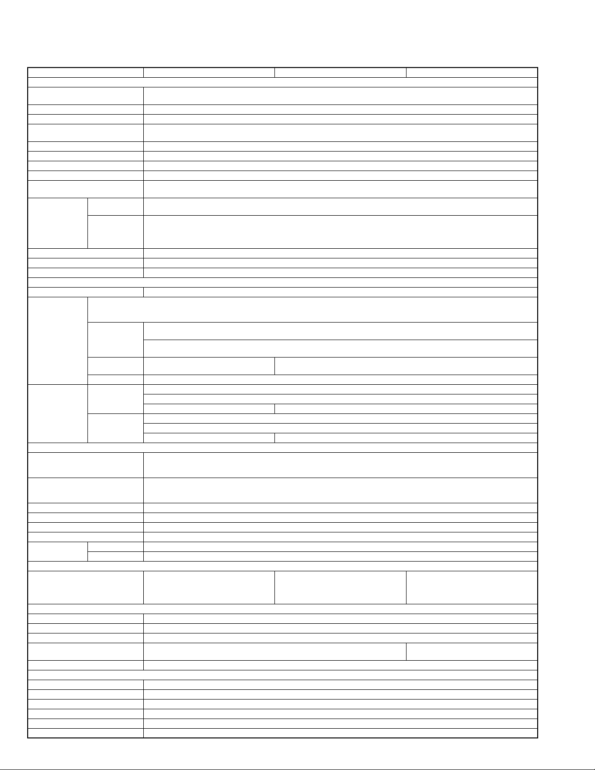
SPECIFICATION
GY-HM150U GY-HM150E GY-HM150EC
General
Power consumption Approx. 8.3 W (when backlight is set to [STANDARD] while the LCD monitor or viewfinder is in use)
Allowable operating temperature 0 °C to 40 ° C (32 °F to 104 °F)
Allowable operating humidity 35 % RH to 80 % RH
Allowable storage temperature -20 °C to 50 °C (-4 °F to 122 °F)
Filter diameter When the hood is
Video/Audio
Video recording file
Video format NTSC setting HD (HQ mode):1920x1080/59.94i, 29.97p, 23.98p, 1440x1080/59.94i, 1280x720/59.94p, 29.97p, 23.98p
Terminals
Audio INPUT1/
INPUT2 terminals
Accessories
AC Adapter
Allowable operating temperature 0 °C to 40 ° C (32 °F to 104 °F)
Remote Control Unit
Allowable operating temperature 0 °C to 40 ° C (32 °F to 104 °F)
Image pickup device 1/4", Progressive CCD × 3
When the hood is
QuickTime File Format(For Final Cut Pro)
format
MP4 File Format (HD only)
AVI File Format (SD only)
Component terminal Y, P
Headphone jack 3.5 mm mini jack (stereo)
Remote terminal 3.5 mm mini jack (4-pin)
Operating distance Approx. 5 m (16.4 ft) (along front axis)
1-2 (No.HC044<Rev.001>)
Power DC 11 V (using AC adapter)
DC 7.2 V (using battery)
Dimensions 366 mm (W) × 179 mm (H) × 138 mm (D)(14-4/8" x 7-1/8" x 5-4/8")
Mass Approx. 1190 g (2.7 Ibs)
Approx. 1320 g (2.9 Ibs) (incl. battery BN-VF823U, SD card, micorophone)
Lens F1.8 to 2.8
f = 3.7 mm to 37 mm
detached
LCD screen 2.7", 16:9, 230,000 pixels
Viewfinder 0.24", 16:9, 260,000 pixels
Recording time Approx. 25 minutes (8 GB SDHC/SDXC card, 35 Mbps, VBR mode)
Video signal HD (HQ mode):MPEG-2 Long GOP
Audio signal LPCM 2ch, 48 kHz/16 Bit
PAL setting HD (HQ mode):1920x1080/50i, 25p, 1440x1080/50i, 1280x720/50p, 25p
AV terminal Video Analog output 1.0 V (p-p), 75 Ω Audio Analog output (stereo)
HDMI terminal HDMI
USB terminal Mini USB-B type, USB 2.0
Dimensions 49 mm (W) × 26 mm (H) × 64 mm (D)(1-15/16" × 1-1/ 8" × 2-7/8")
Battery life Approx. 1 year (varies according to frequency of use)
Dimensions 42 mm (W) × 14.5 mm (H) × 91 mm (D)(1-6/8" × 9/16" × 3-5/ 8")
46 mm (screw pitch: 0.75 mm)
Compatible with filter (external diameter: 50 mm and below),tele-converter, and wide-converter
72 mm (screw pitch: 0.75 mm)
attached
Compatible with filter (external diameter: 75 mm and below) only
* When removing the filter, do not press on the top and bottom of the hood. Doing so makes it difficult to remove the filter and may
damage the inner surface of the hood.
Zoom Up to 10x (optical zoom)
VBR, 35 Mbps (Max) MPEG-2
HD (SP mode):MPEG-2 Long GOP
CBR, 25 Mbps (1440x1080i) /19 Mbps(1280x720p) MPEG-2
SD DV
CBR, 25 Mbps (720x480i)
HD (SP mode):1440x1080/59.94i, 1280x720/59.94p, 29.97p, 23.98p
SD:720x480/59.94i -
HD (SP mode):1440x1080/50i, 1280x720/50p, 25p
- SD:720x576/50i
-8 dBu, 1 k Ω (when reference level -12 dB is selected)
-16 dBu, 1 k Ω (when reference level -20 dB is selected)
, PR component output
B
Y: 1.0 V (p-p), 75 Ω
, PR: 700 mV (p-p), 75 Ω
P
B
TM
Connector
MIC -60 dBu, 3 kΩ, XLR (balanced), +48 V output (phantom power supply)
LINE +4 dBu, 10 k Ω, XLR (balanced)
AC adapter, Power co rd×2, Battery, Battery
charger, Remote control unit, Audio unit,Microphone,AV cord,Component cable,CDROM,Instruction manual,Warranty card
Power AC 100 V to 240 V, 50 Hz/60 Hz
Output DC 11 V =, 1 A
(excluding cord and AC plug)
Mass Approx. 86 g (0.19 Ibs)
Type DC 3 V (button battery CR2025)
Mass Approx. 30 g (0.07 Ibs)(including button battery)
DV
CBR, 25 Mbps (720x576i)
AC adapter, Power co rd×4, Battery, Battery
charger, Remote control unit, Audio unit,Microphone,AV cord,Component cable,CDROM,Instruction manual
AC adapter, Power cord, Remote control
unit, Audio unit,Microphone,AV cord,Component cable,CD-ROM,Instruction manual,Warranty card
47 mm (W) × 28 mm (H) × 72 mm (D)
(excluding cord and AC plug)
Page 3
SECTION 1
r
PRECAUTION
1.1 SAFETY PRECAUTIONS
Prior to shipment from the factory, JVC products are strictly inspected to conform with the recognized product safety and electrical codes of the countries in which they are to be
sold.However,in order to maintain such compliance, it is equally
important to implement the following precautions when a set is
being serviced.
1.1.1 Precautions during Servicing
(1) Locations requiring special caution are denoted by labels
and inscriptions on the cabinet, chassis and certain parts of
the product.When performing service, be sure to read and
comply with these and other cautionary notices appearing
in the operation and service manuals.
(2) Parts identified by the symbol and shaded ( ) parts
are critical for safety.
Replace only with specified part numbers.
NOTE :
Parts in this category also include those specified to
comply with X-ray emission standards for products
using cathode ray tubes and those specified for
compliance with various regulations regarding spurious radiation emission.
(3) Fuse replacement caution notice.
Caution for continued protection against fire hazard.
Replace only with same type and rated fuse(s) as specified.
(4) Use specified internal wiring. Note especially:
• Wires covered with PVC tubing
• Double insulated wires
• High voltage leads
(5) Use specified insulating materials for hazardous live parts.
Note especially:
• Insulation Tape
• PVC tubing
•Spacers
• Insulation sheets for transistors
• Barrier
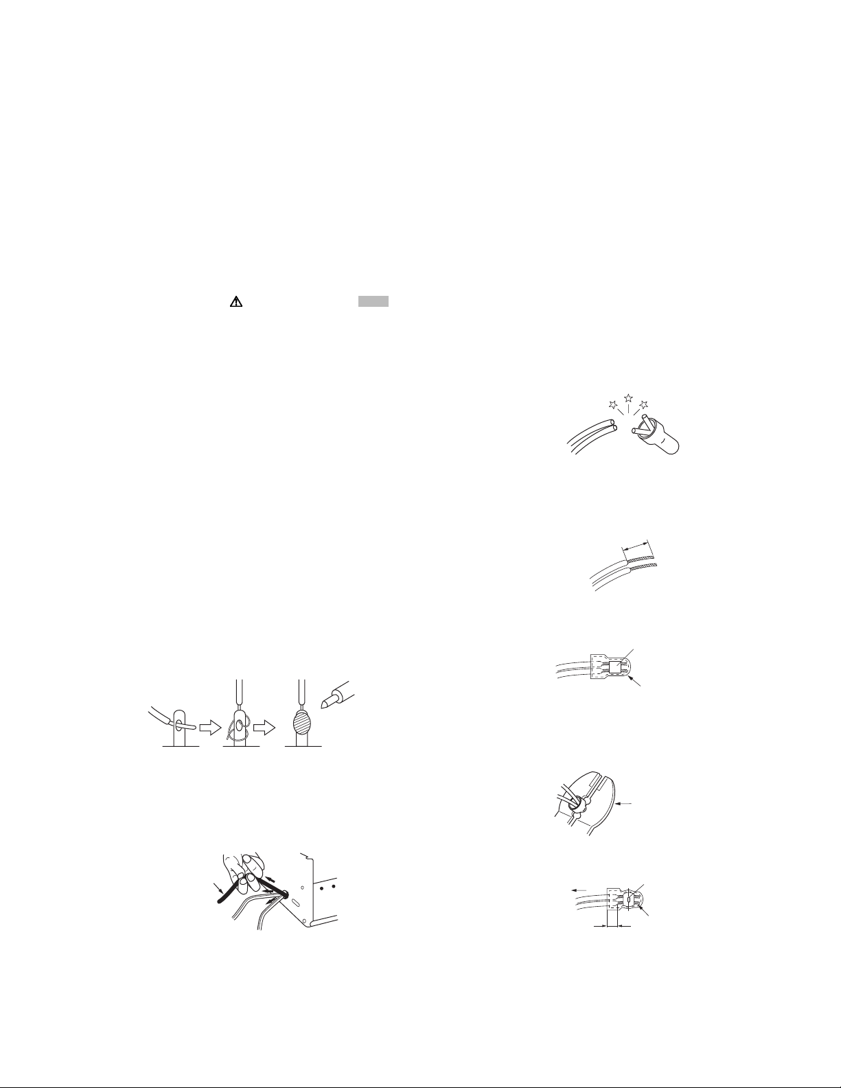
(6) When replacing AC primary side components (transformers,
power cords, noise blocking capacitors, etc.) wrap ends of
wires securely about the terminals before soldering.
Fig.1-1-1
(7) Observe that wires do not contact heat producing parts
(heatsinks, oxide metal film resistors, fusible resistors, etc.)
(8) Check that replaced wires do not contact sharp edged or
pointed parts.
(9) When a power cord has been replaced, check that 10-15
kg of force in any direction will not loosen it.
Power cord
cathode ray tubes and other parts with only the specified
parts. Under no circumstances attempt to modify these circuits.Unauthorized modification can increase the high voltage value and cause X-ray emission from the cathode ray
tube.
(12) Crimp type wire connector In such cases as when replac-
ing the power transformer in sets where the connections
between the power cord and power trans former primary
lead wires are performed using crimp type connectors, if
replacing the connectors is unavoidable, in order to prevent
safety hazards, perform carefully and precisely according
to the following steps.
• Connector part number :E03830-001
• Required tool : Connector crimping tool of the proper
type which will not damage insulated parts.
• Replacement procedure
a) Remove the old connector by cutting the wires at a
point close to the connector.Important : Do not reuse a connector (discard it).
cut close to connector
Fig.1-1-3
b) Strip about 15 mm of the insulation from the ends
of the wires. If the wires are stranded, twist the
strands to avoid frayed conductors.
15 mm
Fig.1-1-4
c) Align the lengths of the wires to be connected. In-
sert the wires fully into the connector.
Metal sleeve
Connector
Fig.1-1-5
d) As shown in Fig.1-1-6, use the crimping tool to
crimp the metal sleeve at the center position. Be
sure to crimp fully to the complete closure of the
tool.
1
.2
2.0
5.5
5
Crimping tool
Fig.1-1-6
e) Check the four points noted in Fig.1-1-7.
Not easily pulled free
Crimped at approx. cente
of metal sleeve
Fig.1-1-2
(10) Also check areas surrounding repaired locations.
(11) Products using cathode ray tubes (CRTs) In regard to such
products, the cathode ray tubes themselves, the high voltage circuits, and related circuits are specified for compliance with recognized codes pertaining to X-ray emission.
Consequently, when servicing these products, replace the
Conductors extended
Wire insulation recessed
more than 4 mm
Fig.1-1-7
(13) Battery replacement caution notice.
CAUTION RISK OF EXPLOSION IF BATTERY IS REPLACED BY AN INCORRECT TYPE.
DISPOSE OF USED BATTERIES ACCORDING TO THE
INSTRUCTIONS.
(No.HC044<Rev.001>)1-3
Page 4
1.1.2 Safety Check after Servicing
Examine the area surrounding the repaired location for damage
or deterioration. Observe that screws, parts and wires have been
returned to original positions, Afterwards, perform the following
tests and confirm the specified values in order to verify compliance with safety standards.
(1) Insulation resistance test
Confirm the specified insulation resistance or greater between power cord plug prongs and externally exposed
parts of the set (RF terminals, antenna terminals, video and
audio input and output terminals, microphone jacks, earphone jacks, etc.).See table 1 below.
(2) Dielectric strength test
Confirm specified dielectric strength or greater between
power cord plug prongs and exposed accessible parts of
the set (RF terminals, antenna terminals, video and audio
input and output terminals, microphone jacks, earphone
jacks, etc.). See Fig.1-1-11 below.
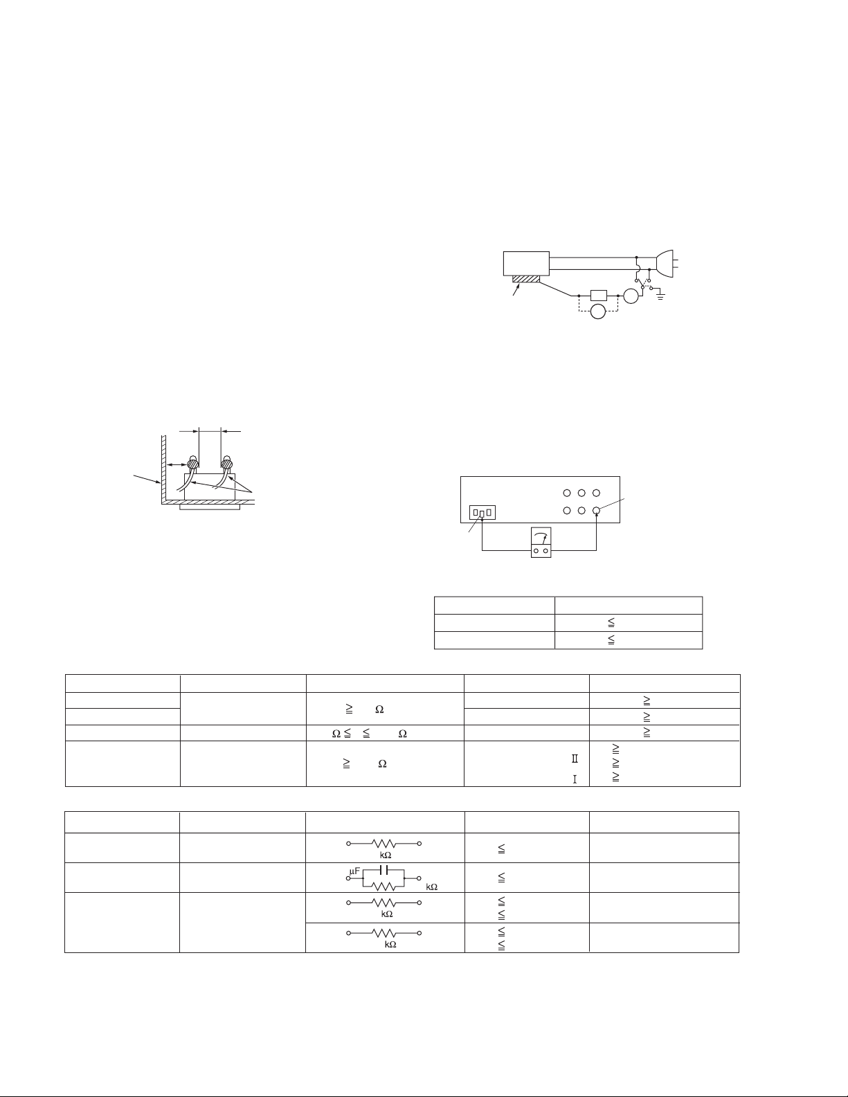
(3) Clearance distance
When replacing primary circuit components, confirm specified clearance distance (d), (d') between soldered terminals, and between terminals and surrounding metallic
parts. See Fig.1-1-11 below.
d
Chassis
d'
Power cord
primary wire
Fig.1-1-8
(4) Leakage current test
Confirm specified or lower leakage current between earth
ground/power cord plug prongs and externally exposed accessible parts (RF terminals, antenna terminals, video and
audio input and output terminals, microphone jacks, earphone jacks, etc.).
Measuring Method : (Power ON) Insert load Z between
earth ground/power cord plug prongs and externally exposed accessible parts. Use an AC voltmeter to measure
across both terminals of load Z. See Fig.1-1-9 and following Fig.1-1-12.
ab
Externally
exposed
accessible part
Z
V
c
A
Fig.1-1-9
(5) Grounding (Class 1 model only)
Confirm specified or lower grounding impedance between
earth pin in AC inlet and externally exposed accessible
parts (Video in, Video out, Audio in, Audio out or Fixing
screw etc.).Measuring Method:
Connect milli ohm meter between earth pin in AC inlet and
exposed accessible parts. See Fig.1-1-10 and grounding
specifications.
AC inlet
Earth pin
Exposed accessible part
MIlli ohm meter
Grounding Specifications
Region
USA & Canada
Europe & Australia
Grounding Impedance (Z
Z 0.1 ohm
Z 0.5 ohm
)
Fig.1-1-10
AC Line Voltage
100 V
100 to 240 V
110 to 130 V
110 to 130 V
200 to 240 V
Region
Japan
USA & Canada
Europe & Australia
Insulation Resistance (R
R 1 M /500 V DC
1 M R 12 M /500 V DC
R 10 M /500 V DC
)
Dielectric Strength
AC 1 kV 1 minute
AC 1.5 kV 1 minute
AC 1 kV 1 minute
AC 3 kV 1 minute
AC 1.5 kV 1 minute
(
Class
(
Class
Clearance Distance (d), (d'
d, d' 3 mm
d, d' 4 mm
d, d' 3.2 mm
d 4 m m
)
d' 8 m m (Power cord
d' 6 m m (Primary wire
)
Fig.1-1-11
AC Line Voltage
100 V
110 to 130 V
110 to 130 V
220 to 240 V
Region
Japan
USA & Canada
Europe & Australia
Load Z
1
0.15
1.5
2
50
Leakage Current (i)
i 1 mA rms
i 0.5 mA rms
i 0.7 mA peak
i 2 mA dc
i 0.7 mA peak
i 2 mA dc
a, b, c
Exposed accessible parts
Exposed accessible parts
Antenna earth terminals
Other terminals
Fig.1-1-12
NOTE :
These tables are unofficial and for reference only. Be sure to confirm the precise values for your particular country and locality.
)
)
)
1-4 (No.HC044<Rev.001>)
Page 5
SECTION 2
r
SPECIFIC SERVICE INSTRUCTIONS
This service manual does not describe SPECIFIC SERVICE INSTRUCTIONS.
SECTION 3
DISASSEMBLY
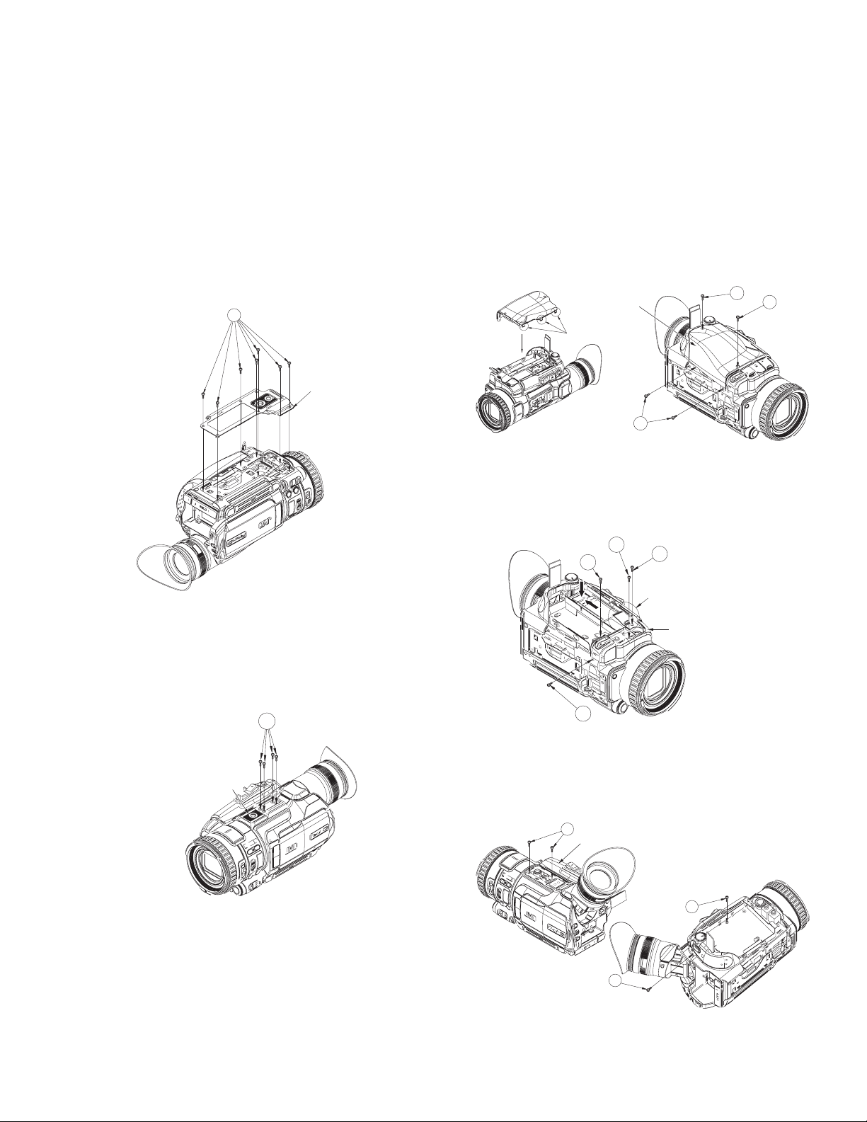
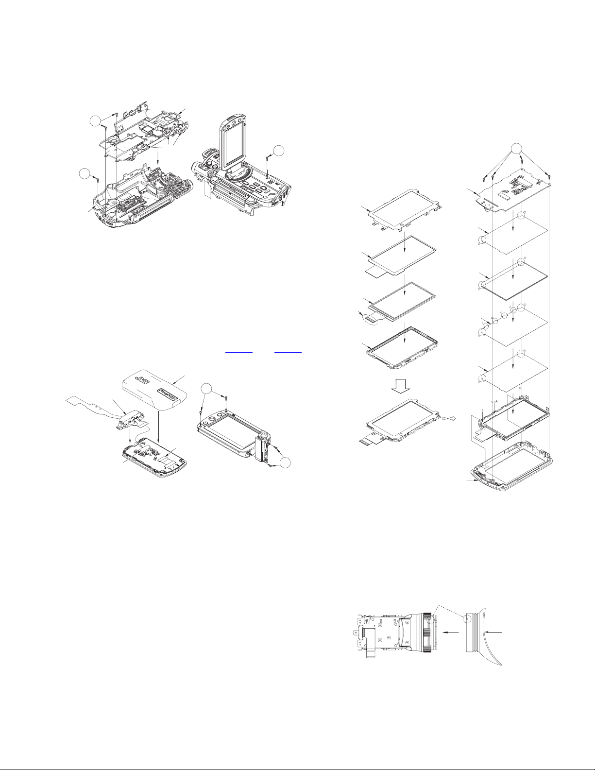
3.1 Removing the bottom cover assembly (See Figure 1)
(1) Remove the seven screws A attaching the bottom cover
assembly.
• The screws indicated with the marks need not be removed.
A
Bottom cove
assembly
Fig.1
3.2 Removing the upper assembly (See Figure 2, Figure 3, Figure 4, Figure 5, Figure 6, Figure 7, Figure 8)
(1) Remove the four screws A attaching the shoe assembly,
then remove the shoe assembly.
A
(2) Remove the four screws B attaching the grip cover, then
remove the grip cover.
• Before attaching the grip cover, attach the three tabs on
the grip cover first.
Grip cover
Tabs
B
B
B
Fig.3
(3) Remove the two screws C and the two screws D attaching
the jack cover, then remove the jack cover.
Screw C: Short Screw D: Long
Open the
mic cover
D
C
aa
C
D
The Jack cover is done in
the slide while pushing arrow
"a" part.
Jack cover assembly
Fig.4
Shoe assembly
Fig.2
(4) Remove the three screws E and the one screw F attaching
the upper cover assembly, then remove the upper cover
assembly.
Screw E: Short Screw F: Long
E
Upper cover assembly
E
F
Fig.5
(No.HC044<Rev.001>)1-5
Page 6
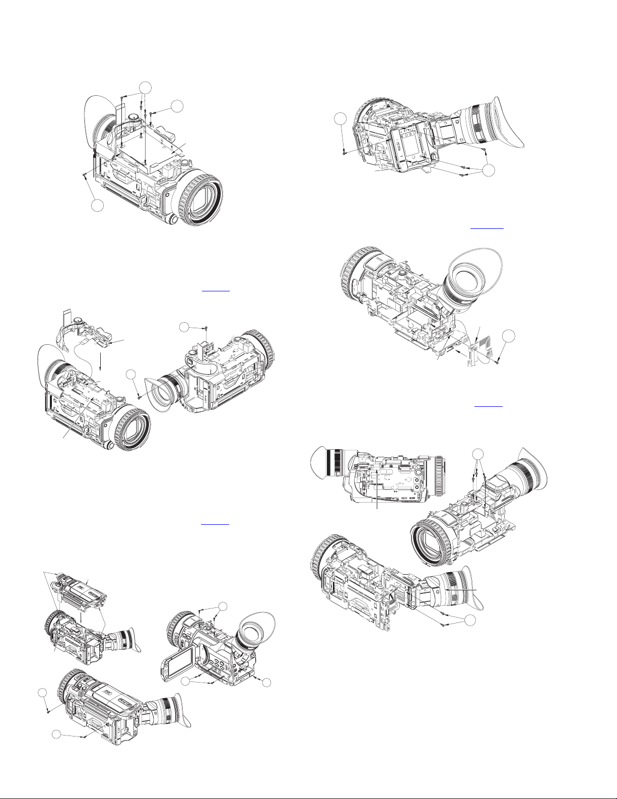
(5) Remove the four screws G and the one screw H attaching
the case (HDD), then remove the case (HDD).
Screw G: Short Screw H: Long
G
H
Case (HDD)
3.3 Removing the view finder assembly (See Figure 9, Figure 10, Figure 11)
(1) Remove the four screws A attaching the rear cover assem-
bly, then remove the rear cover assembly.
A
G
Fig.6
(6) Remove the one screw J and the one screw K attaching
the OPE unit.
Screw J: Short Screw K: Long
(7) Pull out the wire from the connector CN204
on the ANA-
LOG board, then remove the OPE unit.
J
OPE Unit
K
CN204
ANALOG
Board
Fig.7
Rear cover
assembly
A
Fig.9
(2) Remove the one screw B attaching the REAR board.
(3) Pull out the wire from the connector CN6001
on the MAIN
board, then remove the REAR board.
REAR Board
B
CN6001
MAIN Board
Fig.10
(4) Pull out the wire from the connector CN205
on the ANA-
LOG board.
(5) Remove the five screws C attaching the view finder assem-
bly, then remove the view finder assembly.
C
(8) Remove the six screws L and the one screw M attaching
the upper assembly.
Screw L: Short Screw M: Long
(9) Pull out the wire from the connector CN107 on the MAIN
board, then remove the upper assembly.
• When attaching the upper assembly, be sure to set the
two tabs firmly.
Set the tabs firmly
CN107
MAIN Board
L
L
Upper assembly
L
Set the tabs firmly
L
Fig.8
1-6 (No.HC044<Rev.001>)
CN205
ANALOG Board
View finder assembly
C
Fig.11
M
Page 7
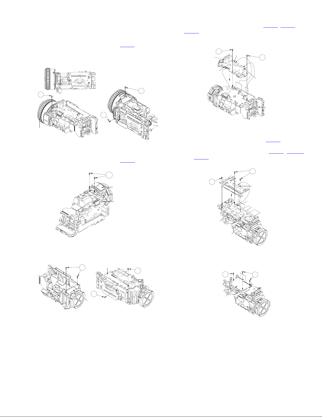
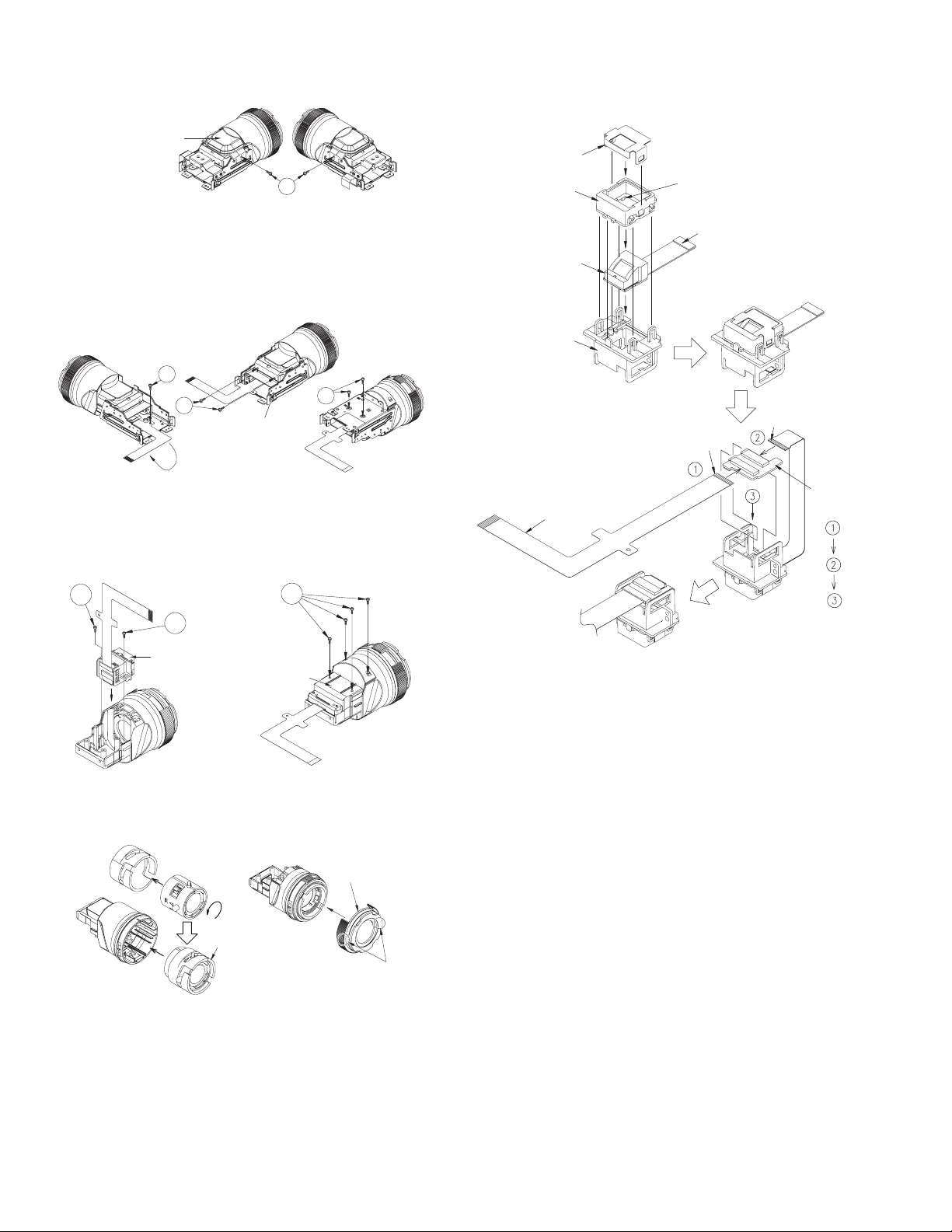
3.4 Removing the boards and the OP block assembly (See
A
Figure 12, Figure 13, Figure14, Figure 15, Figure 16,
Figure 17, Figure 18, Figure 19, Figure 20)
(1) Pull out the wire from the connector CN108
on the MAIN
board.
(2) Remove the three screws A attaching the focus ring as-
sembly, then remove the focus ring assembly.
(6) Pull out the wires from the connectors CN201
on the ANALOG board.
CN203
, CN202, and
(7) Remove the two screws D attaching the ANALOG board,
then remove the ANALOG board.
D
NALOG
Board
CN203
CN201
D
CN202
A
Focus ring
assembly
CN108
MAIN Board
A
A
Fig.12
(3) Remove the two screws B attaching the MIC assembly.
(4) Pull out the wire from the connector CN206
on the ANA-
LOG board, then remove the MIC assembly.
B
MIC Assembly
CN206
Fig.13
(5) Remove the four screws C attaching the bracket (bottom)
and the bracket (frame), then remove each bracket.
Bracket (Bottom)
C
C
CN6003
Fig.15
(8) Remove the three screws E attaching the bracket (MAIN).
(9) Pull out the wire from the connector CN901
on the SD
board, then remove the bracket (MAIN) and the SD board.
(10) Pull out the wires from the connectors CN103
and CN110
on the MAIN board, then remove the MAIN
, CN6003,
board.
E
E
CN110
MAIN
Board
CN901
SD Board
CN103
Fig.16
(11) Remove the three screws F attaching the heat sink (MAIN),
then remove the heat sink (MAIN).
F
F
C
Bracket (Frame)
Heat sink
(MAIN)
Fig.14
Fig.17
(No.HC044<Rev.001>)1-7
Page 8
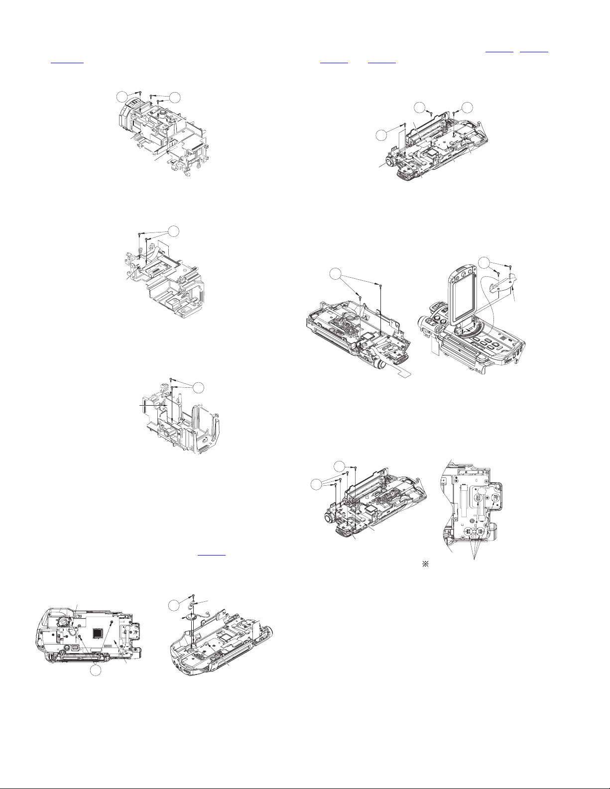
(12) Disconnect the B to B connector from the connector
CN5001 on the CDS board.
(13) Remove the three screws G attaching the OP block assem-
bly, then remove the OP block assembly.
G
OP Block
assembly
CN5001
CDS Board
G
Fig.18
(14) Remove the two screws H attaching the JACK board, then
remove the JACK board.
H
JACK
Board
Fig.19
(4) Pull out the wires from the connectors CN621
and CN626 on the OPE4 board.
CN622
, CN624,
(5) Remove the one screw C and the two screws D attaching
the OPE4 board, then remove the OPE4 board.
Screw C: Silver Screw D: Black
D
CN621
D
CN626
CN624
C
CN622
OPE4 Board
Fig.22
(6) Remove the two screws E attaching the cover (upper), then
remove the cover (upper).
(7) Remove the two screws F attaching the monitor assembly,
then remove the monitor assembly.
E
F
Cover (upper)
(15) Remove the two screws J attaching the CDS board and the
bracket (CDS), then remove the CDS board and the bracket (CDS).
J
CDS Board and
bracket (CDS)
Fig.20
3.5 Removing the upper assembly (See Figure 21, Figure 22, Figure 23, Figure 24, Figure 25)
• Remove the upper assembly from the main unit.
(1) Remove the two screws A attaching the CU sheet, then re-
move the CU sheet.
(2) Pull out the wire from the connector CN623
on the OPE4
board.
(3) Remove the one screw B attaching the speaker, then re-
move the speaker and the bracket (SPK).
Process wire to this notch.
B
Speaker
Bracket (SPK)
Fig.23
(8) Remove the four screws G attaching the OPE2 board and
the OPE3 board, then remove each board.
• When attaching the OPE2 board and OPE3 board, make
sure that each pair of switches and knobs aligns at four
positions.
G
G
OPE3 Board
OPE2 Board
Fix the screws after confirming the
position of switch and knob.
Fig.24
CU Sheet
A
1-8 (No.HC044<Rev.001>)
CN623
Fig.21
Page 9
(9) Remove the two screws H and the one screw J attaching
the frame (upper).
(10) Remove the four tabs, then remove the frame (upper).
(11) Remove the one screw K attaching the OPE1 board as-
sembly, then remove the OPE1 board assembly.
Tab
H
K
Frame (upper)
Tabs
J
(3) Removing the four screws C attaching the bracket (LCD)
enables to release each part.
• When assembling the parts, be careful with the assembling order and direction of each part.
• Do not push the LCD surface as it may be damaged.
• Be careful in handling the surface of the LCD and the
monitor, and do not damage, soil, or leave fingerprints. If
the surfaces are soiled, gently wipe them off with soft
cloth.
C
MONI Board
OPE1
Board
assembly
Fig.25
3.6 Removing the monitor assembly (See Figure 26, Figure
27)
• Removing the monitor assembly from the upper assembly.
(1) Remove the two screws A and the two screws B attaching
the monitor cover assembly, then remove the monitor cover assembly.
Screw A: Narrow Screw B: Thick
(2) Pull out the wires from the connectors CN701
, and CN703
on the MONI board, then remove the hinge unit assembly.
Monitor cover assembly
Hinge unit
assembly
CN703
A
CN701
B
Fig.26
LCD Bracket
Spacer (LCD)
LCD Module
Support plate
side
LCD Case
Sheet (M.REF)
Light guide
Sheet (M.DIFF)
Sheet BEF
Turn
Put it on slit
of MONI case.
MONI Case assembly
Fig.27
3.7 Removing the view finder assembly (See Figure 28, Figure 29, Figure 30, Figure 31, Figure 32, Figure 33)
• Remove the view finder assembly from the main unit.
(1) Remove the eye cap.
• When attaching the eye cap, align the positions as
shown in the figure.
Match and attach this position.
Eye cap
Fig.28
(No.HC044<Rev.001>)1-9
Page 10
(2) Remove the two screws A attaching the upper cover (VF),
then remove the upper cover (VF).
Upper cover (VF)
A
Fig.29
(3) Remove the one screw B attaching the wire.
(4) Remove the two screws C and the two screws D attaching
the holder (VF) assembly, then remove the holder (VF) assembly.
Screw C: Short Screw D: Long
B
C
Holder (VF)
assembly
D
(8) The parts on the LCD module assembly are fixed only with
the tabs. When assembling the parts, be careful with the attaching order and direction of each part.
LCOS Bracket
LCOS Cover
LCD Module
LCOS Holder
Note the boss breaking.
Support plate side
Terminal side
Terminal side
Fig.30
(5) Remove the four screws E attaching the bottom case (VF),
then remove the bottom case (VF).
(6) Remove the two screws F attaching the LCD module as-
sembly, then remove the LCD module assembly.
F
F
LCD Module assembly
Bottom case (VF)
E
Fig.31
(7) Remove the two tabs, then remove the front cover (VF).
• Removing the front cover (VF) enables to release the
lens and other parts.
Front cover (VF)
Lens holder
assembly
VF Board
FPC
Fig.33
1-10 (No.HC044<Rev.001>)
Tabs
Fig.32
Page 11
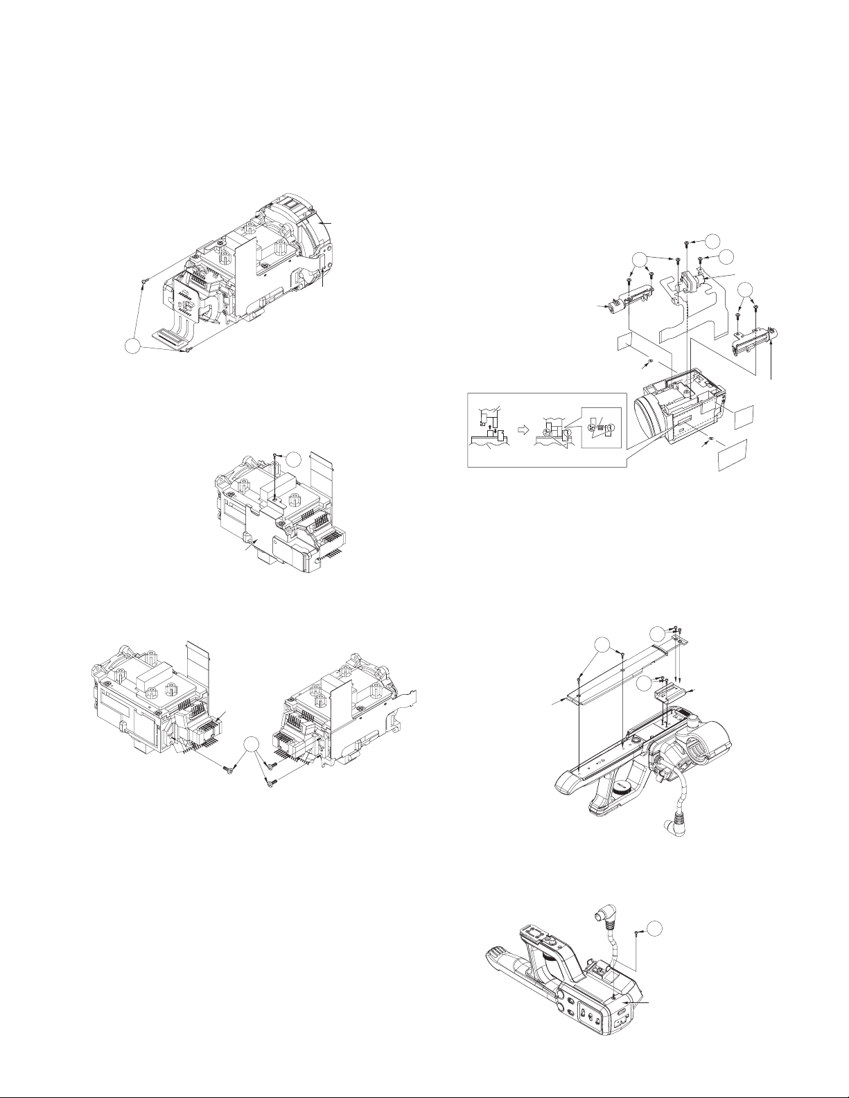
3.8 Removing the OP block assembly (See Figure 34, Fig-
r
ure 35, Figure 36, Figure 37)
• Remove the OP block from the main unit.
(1) Pull out the wire connected to the ROIS unit.
(2) Remove the two screws A attaching the ROIS unit, then re-
move the ROIS unit.
• Do not blow the lens inside the ROIS (on the OP
block) with air. Never touch the lens.
ROIS Unit
Connector
A
Fig.34
(3) Unsolder the soldered points on the CCD board, then re-
move the CCD board.
(4) Remove the one screw B attaching the heat sink (CCD) as-
sembly, then remove the heat sink (CCD) assembly.
B
(6) Unsolder the soldered points on the zoom motor unit and
the focus motor unit.
• Be careful not to break or damage the wire by solder-
ing (overheated).
(7) Remove the six screws D and the one screw E attaching
the iris motor unit, zoom motor unit, and the focus motor
unit, then remove each part.
• As the spring comes off when the zoom motor unit and
the focus motor unit are removed, be careful not to loose
the spring.
• See the figure when attaching the spring.
E
D
Iris motor unit
D
Focus moto
unit
Slide part (Motor side)
Slide part
(OP Block side)
Zoom motor unit
Hook
Hook
D
Spring
Spring
Spring
Fig.37
Heat sink (CCD)
assembly
Fig.35
(5) Remove the three screws C attaching the prism assembly,
then remove the prism assembly.
Prism
assembly
C
Fig.36
3.9 Removing the audio unit (See Figure 38, Figure 39, Figure 40, Figure 41, Figure 42, Figure 43, Figure 44, Figure 45)
(1) Remove the four screws A attaching the cover (TOP), then
remove the cover (TOP).
(2) Remove the two screws B attaching the shoe assembly,
then remove the shoe assembly.
A
Cover (TOP)
A
B
Shoe assembly
Fig.38
(3) Remove the one screw C attaching the AU cover (FR) as-
sembly, then remove the AU cover (FR) assembly.
C
AU Cover (FR) assembly
Fig.39
(No.HC044<Rev.001>)1-11
Page 12

(4) Remove the four screws D attaching the XLR board.
X
r
(5) Pull out the wire from the connector CN2802 on the XLR
board, then remove the XLR board assembly.
D
D
CN2802
D
(9) Remove the two screws H attaching the AU cover (BTM),
then remove the AU cover (BTM).
H
AU Cover (BTM)
Fig.44
XLR Board assembly
Fig.40
(6) Remove the three screws E attaching the AU cover (SW),
then remove the AU cover (SW).
• The slide knob comes off at the same time. When attaching the AU cover (SW), be careful with the direction of the
slide knob.
E
Slide knob
Slide knob
AU Cover (SW)
Fix convex shape of
knob with mark.
Fig.41
(7) Remove the two screws F attaching the audio VR knob,
then remove the audio VR knob.
(10) Remove the four screws J attaching the shoe plate, then
remove the shoe plate, lock screw, and the lock spring.
• See the figure when attaching the shoe plate, the lock
screw, and the lock spring.
J
Shoe plate
Detail of how to fix
Pass the screw a part of
extended slit.
A
Lock spring
Slide screw like arrow afte
pass A of the lock screw
Lock screw
Fig.45
Suppress the outside of knob,
and fix the screw.
attach the knob so that the print
side may become right.
(8) Remove the three screws G attaching the XLR2 board,
then remove the XLR2 board.
1-12 (No.HC044<Rev.001>)
LR2 Board
G
Audio VR knob
F
Fig.42
Fig.43
Page 13

SECTION 4
(
)
(
)
_R_
_G_
_
_
_B_
_
_
_
_
_
_
_
_HD_
_
_
_
_
_R_
_B_
_
_
_
_
_HD_
_
_
_
_
_
_
_G_
_
_
ADJUSTMENT
4.1 INSTRUMENTS REQUIRED FOR ADJUSTMENT AND THE SETUP
4.1.1 Measuring instruments required for adjustment
Instrument Condition Instrument Condition
PC (Windows) With an RS-232C compliant serial
communication port.
Color TV monitor Supporting HD, with an HDMI input. Speaker ----------
Oscilloscope 100 MHz or higher (300 MHz is recom-
mended), calibrated instrument.
Frequency counter With threshold level adjustment. Cali-
brated instrument.
Digital volt meter Calibrated instrument.
4.1.2 Jigs and tools required for adjustment
Self-diagnostic software
PC cable Communication cable Jig connector cable Charging battery
(Service Support System)
YTU94057-121
QAM0099-002 KSJ1742 KSJ1740 KSJ1741
Download from JS-NET
Audio tester Calibrated instrument.
DC power source 12V/1.7A or more, power source for light box.
AC adapter Used as a power source for the unit.
(Accessory : AP-V21)
adjustment jig
Light box INF adjustment lens
Focus chart Step down ring Filter
(Collimator)
YTU93096B YTU92001D YTU92001-018 YTU92001-102
ø46mm→ø36mm
4.1.3 Jig connector cable connection
(1) Remove the seven screws, then remove the bottom cover.
(2) Connect the jig connector cable to the MAIN board CN111.
IC CLIP WIRING
JIG Connector
TO MM0D
TO AL_3.1V
TO IF_RX
TO IF_TX
TO GND
Slide Switch of the Communication Cable
Communication
Cable
Green
Blue
Red
White
Black
Communication
Cable
Normally switched to the mini jack side.
(SSS communication for adjustment)
Only when updating CAM CPU,
switched to the IC clip side.
PC Cable
CAUTION
Before connecting the jig cable, be sure to turn “OFF” the power.
If the jig connector cable is connected while the power is “ON”,
communication error may occur.
When the error occurs, the power supply of unit is turned “OFF”.
JIG Connector Cable (KSJ1740)
JIG CONN
Service
Support
System
121
PC(Windows)
XDSPTRST
XDSPSRST
VF
VF
VF
VF
REG_3.1V
UA
UA
AL_3.1VSYS
DSP
SYS
OCD
VF
DRV
OCD
DSP
DSP
DSP
EXTRGO
DSP
MMOD
KENTO
11
16 2
JIG
23
JIG
17 4
JIG
35
COM_JIG
RXDO
TXDO
TX
IF
IF
RX
RSTL
GND
GND
RTCK
IRU
MVD
GND
18 6
47
19 8
59
20 10
611
21 12
TDI
713
22 14
SCL
815
JIG
23 16
3.0V
917
24 18
SDA
10 19
25 20
11 21
26 22
12 23
TCK
27 24
TDO
13 25
28 26
TMS
14 27
29 28
15 29
30 30
• Color temperature conversion filter.(LBB12)
YTU94152-LBB12
• ND filter (ND1.5)
YTU94152-ND1.5
• ND filter (ND0.3)
YTU94152-ND0.3
JIG CONN BOARDMAIN CN111
PIN No.
XDSPTRST
JIG
VF
JIG
VF
REG
3.1V
TXDO
UA
TX
IF
DSP_TDI
OCD
SCL
3.0V
DRV
OCD_SDA
DSP
RTCK
MVD
DSP
TDO
DSP
TMS
GND
XDSPSRST
VF
JIG
VF_COM_JIG
UA
RXDO
AL_3.1VSYS
IF
RX
SYS_RSTL
VF
JIG
GND
GND
IRU
TCK
DSP
EXTRGO
MMOD
KENTO
(No.HC044<Rev.001>)1-13
Page 14

4.1.4 Set up for adjustment
(1) Connect appropriate measuring instruments, jigs, and tools required for the adjustment item.
Color TV Monitor
Audio Tester
Light Box
Filter
Oscilloscope
Frequency Counter
Audio Signal
75 resistor for termination
Focus Chart
(Insert the filter into the light box.)
Collimator
Step Down Ring
Oscilloscope
Video Signal
Service
Support
System
121
4.2 ADJUSTMENT
The adjustment for this model is a special adjustment using a
PC.
Use the self-diagnostic software SSS (Service Support System)
for adjustment.
4.2.1 Basic usage of the SSS for adjustment
(1) Click [Adjustment Utility] on the main screen of the SSS.
(2) The Adjustment Utility screen is displayed.
• The adjustment items are categorized into the following
six groups.
Click the tab on the Adjustment Utility screen to select.
1) Setting Serial No.
2) Deck Adjustment
3) Camera Adjustment
4) Optical Adjustment
5) Color View Finder (C.VF) Adjustment
6) ROIS Adjustment
(3) Select the item to adjust.
a) Click the [Procedure], then select the adjustment
item from the pulldown menu.
b) Click the selected adjustment item.
(The display shows White Drop Out Pixel of CCD is selected)
(4) Click the [Start] button.
(5) Required procedure for adjustment is displayed on the
screen.
Follow the direction for adjustment.
(6) When the adjustment is completed normally, the box on the
left of the adjustment item is checked.
1-14 (No.HC044<Rev.001>)
Page 15

4.2.2 Setting Serial No.
Measuring
No. Item
Instrument &
Input Signals
1 Setting se-
--- EE
rial number
4.2.3 Deck Adjustment
Measuring
No. Item
Instrument &
Input Signals
1 Built-in MIC
L/R level
• Audio tester
• Speaker
balance
Mode
Mode
EE/Video mode
Measuring Point (A)
Adjustment Points (B)
Adjustment Level (C)
(A)--(B)EEPROM Menu
(C)Serial number
Measuring Point (A)
Adjustment Points (B)
Adjustment Level (C)
(A)A/V OUT (Audio OUT)
(B)60 Hz(NTSC):1710h
50 Hz(PAL) :6710h
(C)Minimize the level differ-
ence between the left and
the right sides.(Should be
within ±2.5dB)
Adjustment Procedure
(1) Input the serial number.
Input a number into the item of "Serial No."
in EEPROM Menu in SERVICE MENU.
(Refer to 5.1.6 EEPROM Menu. A serial
number is 8 figures.)
Adjustment Procedure
• Adjust in 60 Hz(NTSC), the value is also written in the 50 Hz(PAL) address.
(1) Set the unit 20 cm or more distance from
the speaker, facing the built-in MIC
straight to the speaker.
(2) Output about 300 Hz sine-wave sound.
Set the output level so that the audio output of the unit stays 400 to 700mVrms.
(3) Adjust to minimize the level difference be-
tween Lch and Rch.
20 cm or more
Speaker: 300 Hz sine wave
(No.HC044<Rev.001>)1-15
Page 16

4.2.4 Camera Adjustment
Measuring
No. Item
1 White Drop
Out Pixel of
CCD
NOTE
• For white blemish detection, the CCD must be fully warmed up.
- White blemish cannot be detected when the CCD is cold.
- Apply power for more than 60 minutes, then check the internal temperature is 47.5°C or higher (EEPROM data : 43h or
less) with the SSS main screen [Option]→[About Temperature(OP)].
- When the room temperature is low, the CCD may not be fully warmed up. Warm up the internal temperature by wrapping
the unit with antistatic aircap or similar material.
• Inserting an SD card to slot A is required.
(An SD card is required to temporary store the white blemish data obtained from the CCD. When the adjustment is finished,
the data is written in the EEPROM, and the temporary data on the SD card is deleted.)
• Before checking the white blemish correction, unplug the power cord and plug it back in.
(The adjustment only writes the correction data, and actual correction data reading and correction is performed when the
power is turned ON.)
2 Hall gain,
Offset
3 ND Hall
gain, Offset
4 White bal-
ance
Instrument &
Input Signal
--- Internal temper-
--- EE/Video mode
--- EE/Video mode
• Light box
• Collimator
•Filter
(Color temperature conversion LBB12)
Mode
ature of the unit
is 47.5°C or
higher (43h or
less)
EE/Video mode
Measuring Point (A)
Adjustment Point (B)
Adjustment Level (C)
(A)HDMI output
(B)2000h to 3FFFh
(C)Automatic adjustment
(A)--(B)60 Hz(NTSC)
:12C0h,12C1h
136Ah,136Bh
50 Hz(PAL): 62C0h,62C1h
636Ah,636Bh
(C)Automatic adjustment
(A)--(B)60 Hz(NTSC):1330h,1331h
4102h,4103h
50 Hz(PAL): 6330h,6331h
7102h,7103h
(C)Automatic adjustment
(A)--(B) 60 Hz(NTSC)
:122Ah~1239h
50 Hz(PAL): 622Ah~6239h
(C)Automatic adjustment
Adjustment Procedure
(1) Apply power to the unit for more than 60
minutes, then check the internal temperature is 47.5°C or higher (43h or less) using
the SSS.
(2) Start the adjustment.
(3) When the adjustment is completed, the in-
formation screen shows the completion of
the adjustment.
(4) Before checking the white blemish, unplug
the power cord and plug it back in.
• Adjust in 60 Hz(NTSC), the value is also written in the 50 Hz(PAL) address.
(1) Start the adjustment.
(2) When the adjustment is normally finished,
the information screen shows the completion of the adjustment. The color bar is displayed in the unit.
• Adjust in 60 Hz(NTSC), the value is also written in the 50 Hz(PAL) address.
(1) Start the adjustment.
(2) When the adjustment is normally finished,
the information screen shows the completion of the adjustment. The color bar is displayed in the unit.
• Adjust in 60 Hz(NTSC), the value is also written in the 50 Hz(PAL) address.
(1) Attach the collimator (without chart) to the
camera lens.
(2) Shoot the light box.
(3) After the start of the adjustment, the ad-
justment on the low color temperature is
completed, and the confirmation screen
for the continuing adjustment is displayed.
(4) Attach the LBB12 filter, then click OK.
(5) Start the adjustment.
(Adjustment on high color temperature
starts.)
(6) When the adjustment is normally finished,
the information screen shows the comple-
tion of the adjustment. The color bar is dis-
played in the unit.
1-16 (No.HC044<Rev.001>)
Page 17

No. Item
5Minimum/
Maximum
gain
Measuring
Instrument &
Input Signal
• Oscilloscope
•Light box
•Collimator
• ND filter
(ND0.3 ×
2pcs)
(or ND0.6 filter)
Mode
EE/Video mode
Measuring Point (A)
Adjustment Point (B)
Adjustment Level (C)
(A)COMPONENT OUT (Y)
[Minimum gain]
(B) 60 Hz(NTSC)
:12C2h,12C3h
50 Hz(PAL): 62C2h,62C3h
[Maximum gain]
(B) 60 Hz(NTSC)
:12C4h,12C5h
50 Hz(PAL): 62C4h,62C5h
(C)0.70±0.03Vpp
Adjustment Procedure
• Adjust in both 60 Hz(NTSC) and 50 Hz(PAL).
• Adjustment is performed only for the minimum
gain. The value of the minimum gain+1F6h is
written as the maximum gain.
[60 Hz(NTSC) adjustment]
(1) Attach the collimator (without chart) to the
camera lens.
(2) Attach the two ND0.3 filters (or one ND0.6
filter), then shoot the light box.
(3) The component Y output adjusts to the
specified value.
[50 Hz(PAL) adjustment]
(4) Adjust the component Y output to the
specified value in the same way as the
procedure (3).
6 AF filter • Light box
•Collimator
• ND filter
(ND1.5)
• ND filter
(ND0.3)
EE/Video mode
(A)---
(B)60 Hz(NTSC): 13A0h to
13A3h
(C)Automatic adjustment
(B)50 Hz(PAL) :63A0h to
63A3h
(C)Automatic adjustment
• Adjust in both 60 Hz(NTSC) and 50 Hz(PAL).
[60 Hz(NTSC) adjustment]
(1) Attach the collimator (without chart) to the
camera lens.
(2) Attach the ND1.5 filter, then shoot the light
box.
(3) After the start of the adjustment, the ad-
justment on the AGC ON is completed,
and the confirmation screen for the continuing adjustment is displayed.
(4) Change the filter from ND1.5 to ND0.3,
then click OK. (Adjustment of AGC OFF
starts.)
(5) When the adjustment of AGC OFF is com-
pleted, the screen for the continuing adjustment is displayed.
[50 Hz(PAL) adjustment]
(6) Change the filter from ND0.3 to ND1.5,
then, adjust in the same procedure from
(2) to (5).
(7) When the adjustment is normally finished,
the information screen shows the completion of the adjustment. The color bar is displayed in the unit.
(No.HC044<Rev.001>)1-17
Page 18

4.2.5 OP Adjustment
No. Item
1OP adjust-
ment
a)Infinity
sensor
b)Zoom
sensor
c) Multi
points adjustment
d) Backlash
(Focus)
e) Backlash
(Zoom)
f)Tele end
adjustment
g)Sensor
position focus pulse
number
h) Sensor
position
zoom pulse
number
Instrument &
Input Signals
• Light box
• Collimator
• Focus chart
Measuring
Mode
EE/Video mode
Measuring Point (A)
Adjustment Points (B)
Adjustment Level (C)
(A)---
(B)60 Hz(NTSC)
:14E0h,14E1h
50 Hz(PAL)
: 64E0h,64E1h
(B)60 Hz(NTSC)
:14E2h,14E3h
50 Hz(PAL)
: 64E2h,64E3h
(B)60 Hz(NTSC)
: 14E4h to 14EDh
50 Hz(PAL)
: 64E4h to 64EDh
(B)60 Hz(NTSC)
: 14EEh to 14F0h
50 Hz(PAL)
: 64EEh to 64F0h
(B)60 Hz(NTSC)
: 14F1h to 14F3h
50 Hz(PAL)
: 64F1h to 64F3h
(B)60 Hz(NTSC) : 14F7h
50 Hz(PAL): 64F7h
(B)60 Hz(NTSC) : 14F8h
50 Hz(PAL): 64F8h
(B)60 Hz(NTSC) : 14F9h
50 Hz(PAL): 64F9h
(C)Automatic adjustment
Adjustment Procedure
• Adjust in 60 Hz(NTSC), the value is also written in the 50 Hz(PAL) address.
• Items from a) to h) are automatically adjusted.
(1) Attach the collimator + focus chart to the
camera lens.
(2) Shoot the light box.
(3) Start the adjustment.
(4) When the adjustment is normally finished,
the information screen shows the comple-
tion of the adjustment. The color bar is dis-
played in the unit.
1-18 (No.HC044<Rev.001>)
Page 19

4.2.6 ROIS Adjustment
Measuring
No. Item
Instrument &
Input Signals
1 Center po-
--- ---
sition
Mode
Measuring Point (A)
Adjustment Points (B)
Adjustment Level (C)
(A)Label on the ROIS
(B)60 Hz(NTSC)
YAW(Lower digit): 16AAh
YAW(Higher digit): 16ABh
50 Hz(PAL)
YAW(Lower digit): 66AAh
YAW(Higher digit): 66ABh
(C)Write the value in the label
on the ROIS.
Adjustment Procedure
• Adjust in 60 (NTSC), the value is also written
in the 50 Hz(PAL) address.
(1) Note down the value in the label attached
to the ROIS.
(2) Write the 13th, 14th, and the 15th values
to each address.
(3) Write the 20th, 21st, and the 22nd values
in the same way.
2 YAW Hall
--- EE/Video mode
gain, Offset
3 PITCH Hall
--- EE/Video mode
gain, Offset
4 ROIS gain Color TV monitor EE/Video mode
(B)60 Hz(NTSC)
PITCH(Lower digit): 16ACh
PITCH(Higher digit):16ADh
50 Hz(PAL)
PITCH(Lower digit): 66ACh
PITCH(Higher digit):66ADh
(C)Write the value in the label
on the ROIS.
(A)--(B)60 Hz(NTSC):1694h,
1695h, 1698h to 169Bh
50 Hz(PAL): 6694h, 6695h,
6698h to 669Bh
(C)Automatic adjustment
(A)--(B)60 Hz(NTSC): 1696h,
1697h, 169Ch to 169Fh
50 Hz(PAL): 6696h,
6697h, 669Ch to 669Fh
(C)Automatic adjustment
(A)HDMI (or A/V OUT)
[YAW]
(B)60 Hz(NTSC)
YAW(Lower digit): 1690h
YAW(Higher digit): 1691h
50 Hz(PAL)
YAW(Lower digit): 6690h
YAW(Higher digit): 6691h
(C)Minimize lateral image
trembles.
[PITCH]
(B)60 Hz(NTSC)
PITCH(Lower digit): 1692h
PITCH(Higher digit):1693h
50 Hz(PAL)
PITCH(Lower digit): 6692h
PITCH(Higher digit):6693h
(C)Minimize lengthwise image
trembles.
1111098765432
12 22212019181716151413
Higher digit
Lower digit
YAW
Higher digit
Lower digit
PITCH
The higher digit of YAW and PITCH inputs
the value of one digit.
The lower digit of YAW and PITCH inputs
the value of two digits.
• Adjust in 60 Hz(NTSC), the value is also written in the 50 Hz(PAL) address.
(1) The adjustment is started.
(The automatic adjustment is done.)
• Adjust in 60 Hz(NTSC), the value is also written in the 50 Hz(PAL) address.
(1) The adjustment is started.
(The automatic adjustment is done.)
• Adjust in 60 (NTSC), the value is also written
in the 50 (PAL) address.
(1) While vibrating the unit to the YAW direc-
tion, adjust to minimize the tremble of the
TV monitor screen.
(2) While vibrating the unit to the PITCH direc-
tion, adjust to minimize the tremble of the
TV monitor screen.
(No.HC044<Rev.001>)1-19
Page 20

SECTION 5
TROUBLE SHOOTING
5.1 SERVICE MENUS
5.1.1 Modes required serviceing
Press the buttons by the combination of the following table, and press the [MENU] button. Will display the following service menus.
The items in the first layer vary according to the specified buttons being held when the [MENU] button is pressed.
(Characters are displayed on LCD monitor screen or view finder.)
MENU Item Displayed content Activation method
FIRMWARE Firmware (Package) version indi-
cation
VERSION CHECK CPU and Program version indica-
tion
ADVANCED FUNCTION White blemish and camera set-
tings
SERVICE FUNCTION Not used
DIP SW Settings of DIP SW
HOUR METER Power hour meter and slot eject
count
EEPROM Serial number input
IEEE1394ID input
While holding down the [OIS] button and the [MENU] button, turn ON the
power.
Turn ON the power. The following operations are performed while holding down the [OIS] button.
• While holding down the [USER1] button and the [USER2] button,
press the [MENU] button (less than 1 second).
• And the [MENU] button is pressed again.
Turn ON the power. The following operations are performed while holding down the [OIS] button.
• While holding down the [USER1] button and the [USER2] button,
press the [MENU] button (less than 1 second).
• And while holding down the [AF/MF] button, press the [MENU] button.
5.1.2 Operation in the first layer of the service menu
(1) While holding down the specified buttons, press the
[MENU] button.
(2) The first layer of each service menu is displayed.
(3) Press the [Cross-Shaped] buttons to move the cursor ()
to the item to be displayed.
(4) Press the [Set] button or the [Cross-Shaped] button (right)
to select the item.
NOTE :
• During recording, the service menu does not start up.
• To go back to the upper layer, press the [Cross-Shaped]
button (left).
• To cancel the service menu, press the [MENU] button.
5.1.2.1 FIRM WARE VERSION MENU Display
(1) Turn ON the power. (DC power supply and a battery are
necessary. )
(2) While holding down the [OIS] button and the [MENU] but-
ton, turn ON the power. Then, the version of firmware is
displayed.
Update Ready
Firmware SPL2470 V0002
Exit
1-20 (No.HC044<Rev.001>)
Page 21

5.1.2.2 Version of CPU and program display
(1) Turn ON the power. (CAM mode, MENU is undisplayed)
(2) The following operations are performed while holding down
the [OIS] button.
(3) While holding down the [USER1] button and the [USER2]
button, press the [MENU] button (less than 1 second).
(4) While holding down the [OIS] button, the [MENU] button is
pressed again.
(5) Move the cursor to [VERSION CHECK], then press the
[SET] button. Then the version of each CPU and a program
is displayed.
Version Check
Package SPL2470 V0002
CAM SPL2471 V0001
MBE SPL2472 V0002
MBE Loader SPL2473 V0001
EEPROM SPL2476 V0001
FPGA SPL2458 V830A
Back
5.1.2.3 SERVICE MENU display
(1) Turn ON the power. (CAM mode, MENU is undisplayed)
(2) The following operations are performed while holding down
the [OIS] button.
(3) While holding down the [USER1] button and the [USER2]
button, press the [MENU] button (less than 1 second).
(4) While holding down the [OIS] button and the [AF/MF] but-
ton, press the [MENU] button.
Service Menu
Advanced Function...
Service Function...
DIP SW...
Hour Meter...
EEPROM...
Exit
Advanced Function
Pixel Compen Det
OP Temperature 40.0
need over 47.5
Loop Rec Off
Back
o
C
o
C(104.0oF)
Item Parameter
PIXEL
COMPEN
DET*
OP TEMPERATURE
NEED OVER
47.5°C
The temperature information on
OP block is displayed.
In the case of a white blemish adjustment start, it recommends that
it is over this temperature.
LOOP REC OFF Loop REC is OFF.
ON Loop REC is carried out infinitely.
*Available only when the Camera Resolution setting is
1920x1080, and the Frame & Bit Rate setting is 60i(HQ). Otherwise, it becomes a gray display and no selection is available.
5.1.3.1 White blemish detection
(1) Open the MAIN MENU, then set [Camera Resolution] in
[Record Format] to 1920x1080, and [Frame & Bit Rate] to
60i(HQ).
Record Format
System Definition HD(MPEG2)
File Format Quick Time
Camera Resolution 1920x1080
Frame & Bit Rate 60i(HQ)
Aspect Ratio 16:9
Set
Cancel
5.1.3 ADVANCED FUNCTION Menu operation
(1) Refer to 5.1.1 to display the SERVICE MENU.
(2) Move the cursor to [ADVANCED FUNCTION], then press
the [Set] button or the [Cross-Shaped] buttons (up/down) to
change the parameter.
(3) ADVANCED FUNCTION Menu is displayed.
(4) Move the cursor to the item to be changed, then press the
[Set] button or the [Cross-Shaped] button (right).
(5) The parameter blinks. Press the [Cross-Shaped] buttons
(up/down) to change the parameter.
(6) Press the [Set] button to set the parameter. The parameter
lights up.
(7) Move the cursor to [BACK], then press the [Set] button or
the [Cross-Shaped] button (right) to go back to the upper
layer and finish the setting.
NOTE :
• To cancel the parameter setting change, press the [CrossShaped] button (left) while the item is chosen.
(2) Open the ADVANCED FUNCTION Menu, choose the [PIX-
EL COMPEN DET], and then press the [Set] button.
[PIXEL COMPEN DET]
Since it is displayed as Detect Pixel Compensation?, [Detect] is chosen and the [SET] button is pressed.
Advanced Function
Pixel Compen Det
OP Temperature 42.5
need over 47.5
Loop Rec Off
Detect Pixel Compensation?
Back
o
C
Advanced Function
Detect
Cancel
o
C(108.5oF)
NOTE:
An error is displayed when SD card is not inserted.
(No.HC044<Rev.001>)1-21
Page 22

PIXEL COMPEN
ERROR
SD CARD
TURN POWER OFF
AND ON AGAIN.
(3) [PIXEL COMPEN EXECUTING] is displayed and the de-
tection required for white blemish correction automatically
starts.
At this time, the camera lens is closed and the mode
changes to the SLOW SHUTTER mode.
PIXEL COMPEN
EXECUTING
5.1.4 DIP SW Menu Operation
(1) Refer to 5.1.1 to display the SERVICE MENU.
(2) Move the cursor to [DIP SW], then press the [Set] button or
the [Cross-Shaped] button (right).
(3) The DIP SW MAIN Menu is displayed.
--- DIP SW ---
DIPSW ALL RESET
DIP SW 0-7..
DIP SW 8-15..
DIP SW 16-23..
DIP SW 24-31..
DIP SW 32-39..
DIP SW 40-47..
DIP SW 48-55..
DIP SW 56-63..
BACK
--- DIP SW 1/8 ---
DIP SW 0 0
DIP SW 1 Off
DIP SW 2 Off
DIP SW 3 Off
DIP SW 4 Off
DIP SW 5 Off
DIP SW 6 Off
DIP SW 7 Off
BACK
(4) When the white blemish detection completes, the result
data is stored in the CPU memory, and an end message is
displayed as shown below. Turn OFF the power.
(After completing white blemish detection, the "Camera
Resolution" and "Frame & Bit Rate" settings return to the
original settings.)
PIXEL COMPEN
END
TURN POWER OFF
AND ON AGAIN
(5) If any errors occur during the detection, an error message
is displayed, then the screen returns to the MENU display.
Message Error details Operation
LENS NOT
CLOSED?
COUNT
OVER
The lens does not close
for detection.
The number exceeds
the specified count.
No result is stored in the
EEPROM.
Only the specified
count of data is stored
in the EEPROM.
--- DIP SW 2/8 ---
DIP SW 8 Off
DIP SW 9 Off
DIP SW 10 Off
DIP SW 11 Off
DIP SW 12 Off
DIP SW 13 Off
DIP SW 14 Off
DIP SW 15 Off
BACK
--- DIP SW 3/8 ---
DIP SW 16 Off
DIP SW 17 Off
DIP SW 18 Off
DIP SW 19 Off
DIP SW 20 Off
DIP SW 21 Off
DIP SW 22 Off
DIP SW 23 Off
BACK
--- DIP SW 4/8 ---
DIP SW 24 Off
DIP SW 25 Off
DIP SW 26 Off
DIP SW 27 Off
DIP SW 28 Off
DIP SW 29 Off
DIP SW 30 Off
DIP SW 31 Off
BACK
1-22 (No.HC044<Rev.001>)
Page 23

--- DIP SW 5/8 ---
DIP SW 32 Off
DIP SW 33 Off
DIP SW 34 Off
DIP SW 35 Off
DIP SW 36 Off
DIP SW 37 Off
DIP SW 38 Off
DIP SW 39 Off
BACK
--- DIP SW 6/8 ---
DIP SW 40 Off
DIP SW 41 Off
DIP SW 42 Off
DIP SW 43 Off
DIP SW 44 Off
DIP SW 45 Off
DIP SW 46 Off
DIP SW 47 Off
BACK
--- DIP SW 7/8 ---
DIP SW 48 Off
DIP SW 49 Off
DIP SW 50 Off
DIP SW 51 Off
DIP SW 52 Off
DIP SW 53 Off
DIP SW 54 Off
DIP SW 55 Off
BACK
--- DIP SW 8/8 ---
DIP SW 56 Off
DIP SW 57 Off
DIP SW 58 Off
DIP SW 59 Off
DIP SW 60 Off
DIP SW 61 Off
DIP SW 62 Off
DIP SW 63 Off
BACK
Refer to 5.1.3 ADVANCED FUNCTION Menu because the operations are almost the same.
NOTE :
ALL DIP switches are factory use only.
These DIP switches are not used for repair or maintenance.
Therefore all DIP Switch settings which are shown below
should not be changed. And do not forget to return to the initial
position, if setting was changed.
Item Parameter
DIP SW
ALL RESET
CANCEL
RESET
Cancel to reset all DIPSW
settings.
Execute to reset all DIPSW
settings.
DIP SW 1/8 DIP SW 0 0 Change prohibited.
DIP SW 1 to 7 OFF Change prohibited.
DIP SW 2/8 DIP SW 8 to 15 OFF Change prohibited.
DIP SW 3/8 DIP SW 16 to 23 OFF Change prohibited.
DIP SW 4/8 DIP SW 24 to 31 OFF Change prohibited.
DIP SW 5/8 DIP SW 32 to 39 OFF Change prohibited.
DIP SW 6/8 DIP SW 40 to 47 OFF Change prohibited.
DIP SW 7/8 DIP SW 48 to 55 OFF Change prohibited.
DIP SW 8/8 DIP SW 56 to 63 OFF Change prohibited.
(Bold is the factory setting.)
5.1.5 HOUR METER Menu Operation
(1) Refer to 5.1.1 to display the SERVICE MENU.
(2) Move the cursor to [HOUR METER], then press the [Set]
button or the [Cross-Shaped] button (right).
(3) The HOUR METER Menu is displayed.
Hour Meter
Power 000006
Slot Eject A 000001
Slot Eject B 000001
Back
Refer to 5.1.3 ADVANCED FUNCTION Menu because the operations are almost the same.
Item Parameter
POWER 000000 Displays the power hour meter.
RESET Resets the power hour meter.
SLOT
EJECT
000000 Displays the slot A and B eject count.
RESET Resets the slot A and B eject count.
(No.HC044<Rev.001>)1-23
Page 24

5.1.6 EEPROM Menu Operation
(1) Refer to 5.1.1 to display the SERVICE MENU.
(2) Move the cursor to [EEPROM], then press the [Set] button
or the [Cross-Shaped] button (right).
(3) The EEPROM Menu is diaplayed.
Item Parameter
Model ID 0 01h Factory use.
1 4F Factory use.
2 8B Factory use.
Node Uniq 0 00h Not use.
1 00h to FFh The left of a serial number to the 1st
figure, and the 2nd figures.
2 The left of a serial number to the 3rd
figure.
3 The left of a serial number to the 4th
figure, and the 5th figures.
4 The left of a serial number to the 7th
figure, and the 8th figures.
Serial No. 0 00h to FFh The left of a serial number to the 1st
figure. (*1)
1 The left of a serial number to the 2nd
figure. (*1)
2 The left of a serial number to the 3rd
figure. (*1)
3 The left of a serial number to the 4th
figure. (*1)
4 The left of a serial number to the 5th
figure. (*1)
5 The left of a serial number to the 6th
figure. (*1)
6 The left of a serial number to the 7th
figure. (*1)
7 The left of a serial number to the 8th
figure. (*1)
All Reset CANCEL Does not reset.
Reset * The data of EEP-ROM is returned
to a setup at the time of factory shipments. (Adjustment data and hour
meter data are excluded.)
* A setup at the time of shipment
changes with sale areas. (I: Japan,
U: America, E: Europe, EC: China)
(*1):It sets to the code changed according to the conversion table of the following table.
Number Input code
030h
131h
232h
333h
434h
535h
636h
737h
838h
939h
G47h
M4Dh
V56h
1-24 (No.HC044<Rev.001>)
Page 25

5.2 HOW TO UPDATE THE FIRMWARE
NOTE:
• When replacing MAIN board, the firmware update is required to maintain combination with other CPU versions.
• Do not turn OFF the power during the update, Otherwise the CPU may be destroyed and replacement of IC or board may be
required.
• Use both an AC adapter and a battery during update. (Do not connect the USB cable.)
• When update is failed, it is displayed on LCD as "UPDATE ERROR!" and LED of SLOT A and SLOT B blinks simultaneously.
If write protected of SD card is opened at this time (write-in permission), the log file "UPDLOG.TXT" will be written out.
Therefore, it understands which device was NG.
• Remove the IEEE1394 cable, or it may cause troubles on the GY-HM150.
• Do not format the SD memory card by PC.
The SD memory card formatted on the PC may not work correctly. Format the SD memory card on the GY-HM150 if formatting
is required.
• You can also use the SD memory cards formatted with digital still cameras, or formatted using formatting software supplied from
SD memory card manufacturer such as Panasonic.
5.2.1 Preparation (Copy the firmware to SD memory card)
NOTE:
• The update file is named as "GY-HM150.UPD".
• The update file should be put on the directory "//PRIVATE/JVC/GY-HM150", otherwise the update is not executed.
(1) Download the update file from JS-NET SMIS and unzip it to a PC.
(2) Insert the SD memory card to the PC and confirm that no file is in the SD memory card. If there are some files, delete them.
(3) Below the "PRIVATE" folder of an update file is copied to SD memory card.
5.2.2 Update procedure
(1) A battery (10-minute or more use is possible) and an AC adaptor are connected to a main unit.
(2) While pressing the [MENU] and [OIS] buttons, turn ON the power. The UPDATE READY menu is displayed and version of firm-
ware is displayed.
Update Ready
Firmware SPL2470 V0002
Exit
Push the [SET] button.
A
UPDATE READY
(3) Insert the SD memory card into the card slot B.
Note:
Can not be updated with slot A.
(4) The updating is started automatically, after the SD memory card was inserted.
Progress bar is displayed on the LCD display while updating.
The LED of SD card slot B blinks and LED of the slot A turned off.
LCD display
Updating
Don't Turn Power Off
...
----
MF
(No.HC044<Rev.001>)1-25
Page 26

(5) When the update is completed, LEDs of SD card slot A and slot B blink slowly. It takes about 3 minutes to complete the update.
Complete is displayed on the LCD display.
LCD display
Complete
(6) After complete the updating, remove the SD memory card.
(7) Turn OFF the power and an AC adapter and a battery are removed.
(8) Connect a battery and an AC adapter again and check the CPU version.
Note :
Confirm the firmware in the SD card if the "update can't be Executed !" was displayed on the LCD display.
(The LEDs of SD card slot A and slot B blink alternately, when update can not be executed.)
LCD display
Update can't be Executed !
Note:
Check the defect of board or the connection of each board, if the "update error !" was displayed.
LCD display
Update Error !
5.3 PRECAUTIONS WHEN CHANGING BOARDS
After changing the board in service, firmware version update and adjustment may be required.
Make sure to perform version update after changing the MAIN board.
1-26 (No.HC044<Rev.001>)
Page 27

5.4 Checking emergency history with SSS
Emergency history can be checked using SSS.
(1) On the SSS main screen, click [Emergency Utility].
5.4.2 Deleting emergency history
(1) Click [Erase All] on the Emergency Utility screen to delete
emergency history.
(2) Click [Read] on the Emergency Utility screen.
(3) Emergency history is displayed.
NOTE
• Emergency history is recorded in HISTORY-1 to HISTORY-4 in the occurrence order. After the 5th error, HISTORY-4 is overwritten.
• Emergency history is recorded in the EEPROM data. When
all relevant repair work is completed, delete the ERROR
HISTORY.
5.4.3 Emergency display detail
Emergency detail Cause
V INFO ERROR
(Video management file
error)
→When data recovery is
possible, recovery
screen is displayed.
Press [OK] to execute
the recovery.
If recovery is impossible, formatting is required.
MEDIA ERROR
(Media initialization error)
Buffer over flow
• Only the number.
• Can be checked with
SSS (No display on the
unit).
(1)During video recording:
•SD card is removed.
•Power is disconnected or interrupted.
(2)During video editing (Delete/OK
mark/Copy):
•SD card is removed.
•Power is disconnected or interrupted.
(3)Data failure in the card due to
other cause.
• SD card failure.
• SD card terminal connection fail-
ure.
• Card removal right after insertion.
• Due to fragmentation of the SD
card, writing speed deteriorates.
• Copy the necessary data, then
format the SD card.
5.4.1 Saving emergency history
(1) Click [Save] on the SSS main screen.
(2) Save the file with a proper name in a proper location.
(3) To open the saved file, [OPEN] is clicked.
5.4.4 Countermeasure on emergency
If the above emergencies occur, check the SD card or the handling of the SD card.
(1) Check if the SD card terminal is dirty or there is any foreign
material.
(2) After copying the necessary data, format the SD card.
(3) Use recommended SD cards.
(Panasonic, TOSHIBA, or SanDisk)
Using cards other than those specified above may prevent
data from being recorded correctly or result in loss of data.
(4) Do not remove the SD card until card recognition is com-
pleted. (The SD card is not extracted until changing lighting
the access lamp of the card slot.)
(5) While the access lamp is blinking, do not remove the SD
card. Data could be broken.
*If the error is not corrected after checking/replacing
(using normal SD card), or properly handling the SD
card, failure in the main unit is considered.
(No.HC044<Rev.001>)1-27
Page 28

5.5 EEPROM
GY-HM150 has an EEPROM (MAIN board IC1005) for data storage.
When the MAIN board or the EEPROM is replaced, initial value
data writing is required. Readjustment is also required because
the adjustment data is reset.
Using SSS (Service Support System) enables writing, reading
(backup), and changing EEPROM data.
Fixed data Data that not change by CPU.
(Model code, etc.)
Adjusting data Data that is changed by adjustment.
(Adjustment data)
No Fixed data Data that may be changed by CPU.
(Focus/Zoom position memory, etc.)
Default setting data Data that is changed by usage
(Menu setting, emergency data, etc.)
Doctor data Doctor program (Data that not change.)
PE data Data that is used during production.
5.5.1 EEPROM initial data writing
Caution
• Before starting EEPROM data writing, be sure to turn OFF
the power dial of the unit.
• The initial value data is reset, except the fixed value and the
doctor program. Therefore, it is necessary to readjust SECTION 4.
• When the backup data writing of EEPROM, the initial value
data need not be written.
(3) When the Initial and Original file navigator screen appears,
select the SSS folder. Selecting an Object Model automat-
ically displays files that conform to each CPU version.
(4) Click the Conformity file [M9H7-HM100**-MP-*.ROM].
(5) Click [OK].
(6) “Initial data for "GY-HM150**" was loaded on the map.” is
displayed. Click [OK].
(7) The initial data is displayed on the EEPROM Utility screen.
Make sure that the power dial of the unit is turned OFF,
then click [Write].
(1) Click [EEPROM Utility] on the SSS main screen.
(2) Click [Open].
(8) Although the initial data is written, the adjustment data is
reset. Readjust the unit.
5.5.2 EEPROM data backup
EEPROM data can be backed up using SSS. The backed up EEPROM data can be rewritten in the unit.
(1) Click [EEPROM Utility] on the SSS main screen.
(2) When the EEPROM Utility screen appears, click [Read].
1-28 (No.HC044<Rev.001>)
Page 29

(3) After reading the EEPROM data, click [Save].
(4) Save the file as a proper name with a serial number in a
proper location. (Extension is XXXXXX.rom)
5.5.3 EEPROM backup data (original file) writing
Caution
• Before starting EEPROM data writing, be sure to turn OFF
the unit.
• The EEPROM data is the one at the time of the backup. The
adjustment data and the EEPROM version are also the
ones at the time of backup. It is likely to differ from an original version, Adjust the unit or update the EEPROM version
as required.
(1) Specify the location of the backup file saved in 5.2.1 EE-
PROM initial value data writing procedure (3) on the Initial
and Original file navigator screen.
(2) Click Original in Object Model.
(3) Find the target file by the file name from among the dis-
played files.
Select the Conformity file, then click [OK].
5.5.4 EEPROM version check
(1) On the SSS main screen, click [EEPROM Utility].
(2) When the EEPROM Utility screen appears, click [Read].
(3) The EEPROM data is read, and the EEPROM version is
displayed in the right bottom of the screen. (CAM and ARM
versions are also displayed.)
(4) The backup data is displayed in the EEPROM Utility
screen. Make sure that the power dial of the unit is turned
OFF, then click [Write].
(No.HC044<Rev.001>)1-29
Page 30

5.6 SSS (Service Support System)
5.6.1 Installation
(1) Download SSS (Service Support System) from JS-NET.
(2) As the downloaded file is a Zip file, extract the file on the PC.
(3) SS121_*** folder is created. Double click the SETUP.EXE in the SS121_*** folder.
(4) Follow the instruction to install the SSS.
5.6.2 Start up
(1) Connect the unit and a PC. (For the connection, refer to 4.1.3 JIG connector cable connection.)
(2) Select [Start]-[All Programs]-[Service Support System]-[SSS121 GY-HM100].
(3) Select the COM port, then click [OK].
(4) The SSS main screen appears.
(5) If there is an error in the communication with the unit, a “Communication error” message is displayed at the bottom of the screen
(status bar).
Recheck the connection between the unit and the PC.
1-30 (No.HC044<Rev.001>)
Page 31

5.6.3 Main screen structure and functions
(1) The main screen consists of Menu bar, Tool bar, and Status bar.
Menu bar Tool bar
Status bar: SSS button explanation and other items are displayed.
(2) Menu Bar
(1)File
Inspector Opens the Inspector screen. Views internal information of the unit.
Controller DSP (Opens the DSP controller screen). Switches ON/OFF the built-in color bar, grayscale.
Information Emergency Utility. Opens the emergency utility screen.
Total Time Information. Checks/Deletes the media access total time, power on total time.
OP information.
EEPROM Utility Opens the EEPROM Utility screen.
Adjustment Utility Opens the Adjustment Utility screen.
Exit Exits the SSS.
(2)Option
Set Clock Sets the clock of the unit. Sets the time of the connected PC to the unit.
About CPU Checks the CPU version. Checks the versions of camera CPU and ARM CPU.
About Temperature(OP) Checks the internal temperature of the unit.
About Frame No Checks the frame No. Checks the model name, frame No.
(3)Help Checks the SSS version.
(3) Tool bar
(1) Inspector Rx : Received data. Checks the zoom/focus operations. communication condition.
Rxd120 : Received data (120). Displays area level of the screen divided into 120.
Z.Track. Checks zoom tracking (The left side is a curve of infinity.).
(2) DSP Controller Switches ON/OFF the built-in color bar, grayscale.
(3) EEPROM Utility Opens the EEPROM Utility screen.
(4) Emergency Utility Opens the Emergency Utility screen.
(5) Total Time Information Checks/Deletes media access (record & playback) total time, power on total time.
(6) Adjustment Utility Opens the Adjustment Utility screen.
(7) Zoom Control (Tele) Moves zoom to Tele end. Using both [CTRL] & [SHIFT] enables variable speed zoom.
(8) Zoom Control (Wide) Moves zoom to Wide end.
Simultaneous clicking the left & right enables move to the Wide end.
(9) Focus Control (Far) Moves the focus to the Far end. Using both [CTRL] & [SHIFT] enables variable focus.
(10)Focus Control (Near) Moves the focus to the Near end.
Simultaneous clicking the left & right enables move to the Far end.
(11)Auto Focus Giving check in Auto Focus enables auto focus.
(No.HC044<Rev.001>)1-31
Page 32

5.6.4 EEPROM Utility
(1) EEPROM Utility screen structure and functions.
Menu bar
(2) Menu bar
Status bar
(9)(7)(5)(3)(1)
(10)(8)(6)(4)(2)
(1) Initial Rom Data Navigator Open Opens data saved in the disk. * For details refer to 5.5 EEPROM.
(2) Open Opens data saved in the disk.
(3) Save Saves data to the disk. * For details refer to 5.5 EEPROM.
(4) Read Reads data from the EEPROM of the unit. * For details refer to 5.5 EEPROM.
(5) Write Writes data to the EEPROM of the unit. * For details refer to 5.5 EEPROM.
(6) Edit Edits the EEPROM data.
(7) Comparison Compares with the data saved in the disk. Difference is displayed in dark color.
(8) Load Doctor Date Downloads only the doctor data from the saved data in the disk.
(9) Print Prints data.
(10)Copy Copies data to the clipboard.
(3) Status bar
(1) Address Displays the selected address value.
(2) Data Displays the data value written in the selected address.
(3) Kind of data Six types of data: Fixed value, adjustment value, variable value, factory setting value, doctor
program, factory data value.
(4) CPU version (CAM CPU, ARM CPU) Displays the CPU versions of camera, ARM.
• [Read] enables to display the CPU version of the connected unit.
• [Open] enables to display the version written in the file.
(5) EEPROM version Only when performs [Read], displays the EEPROM version of the connected unit.
1-32 (No.HC044<Rev.001>)
Page 33

(4) Data
There are six types of EEPROM data. Each data is displayed in different color on the EEPROM Utility screen.
Color Type Description Details
Light blue Fixed data Data that not change by CPU. Model code, etc.
Pink Adjusting data Data that is changed by adjustment. Adjustment data.
Light green No Fixed data Data that may be changed by CPU. Focus/Zoom position memory, etc.
Orange Default setting data Data that is changed by usage. Menu setting, emergency, etc.
Dark magenta Doctor data Data that not change. Doctor program.
Yellow PE data Data that not change. Data that is used during production.
5.6.5 Temperature information
(1) On the SSS main screen, click [Option]-[About Temperature (OP)] to check the internal temperature (internal temperature near
OP).
• The CCD needs to be fully warmed up for white blemish correction. The internal temperature of the unit (the temperature near
OP) must be 47.5°C or higher (43h or less).
Check the internal temperature in About Temperature (OP).
Before correcting white blemish,
check that the internal
temperature is 47.5 C or higher.
(EEPROM data:43h or less)
5.6.6 Non-communication mode
In the non-communication mode, The SSS can be used without connecting the unit. The EEPROM saved in the disk can be checked.
(1) On the “Serial Port Configuration” screen in starting the SSS, press and hold the “L” key on the keyboard, then click [OK].
Press and hold, then click
(2) A warning screen appears, click [OK].
(No.HC044<Rev.001>)1-33
Page 34

5.6.7 File structure
In the directory where the SSS is installed, there are following two files: “SSS121.STT”, and “SSS121.INI”
(1) SSS121.STT
This file is required to enable the EEPROM Utility color display. If this file is deleted, the EEPROM Utility screen changes to all
white.
(2) SSS121.INI
Each screen size and position used in the SSS is written when the SSS is finished. When starting the next time, the SSS is in
the latest settings.
To return all items to the initial settings, delete this file. (Even if this file is deleted, the file will be recreated when the SSS is
finished.)
1-34 (No.HC044<Rev.001>)
Page 35

JVC KENWOOD Corporation
Professional Systems Business Group, Business Solution Div.
(No.HC044<Rev.001>)
Printed in Japan
VSE
 Loading...