

Page 1
86700200304
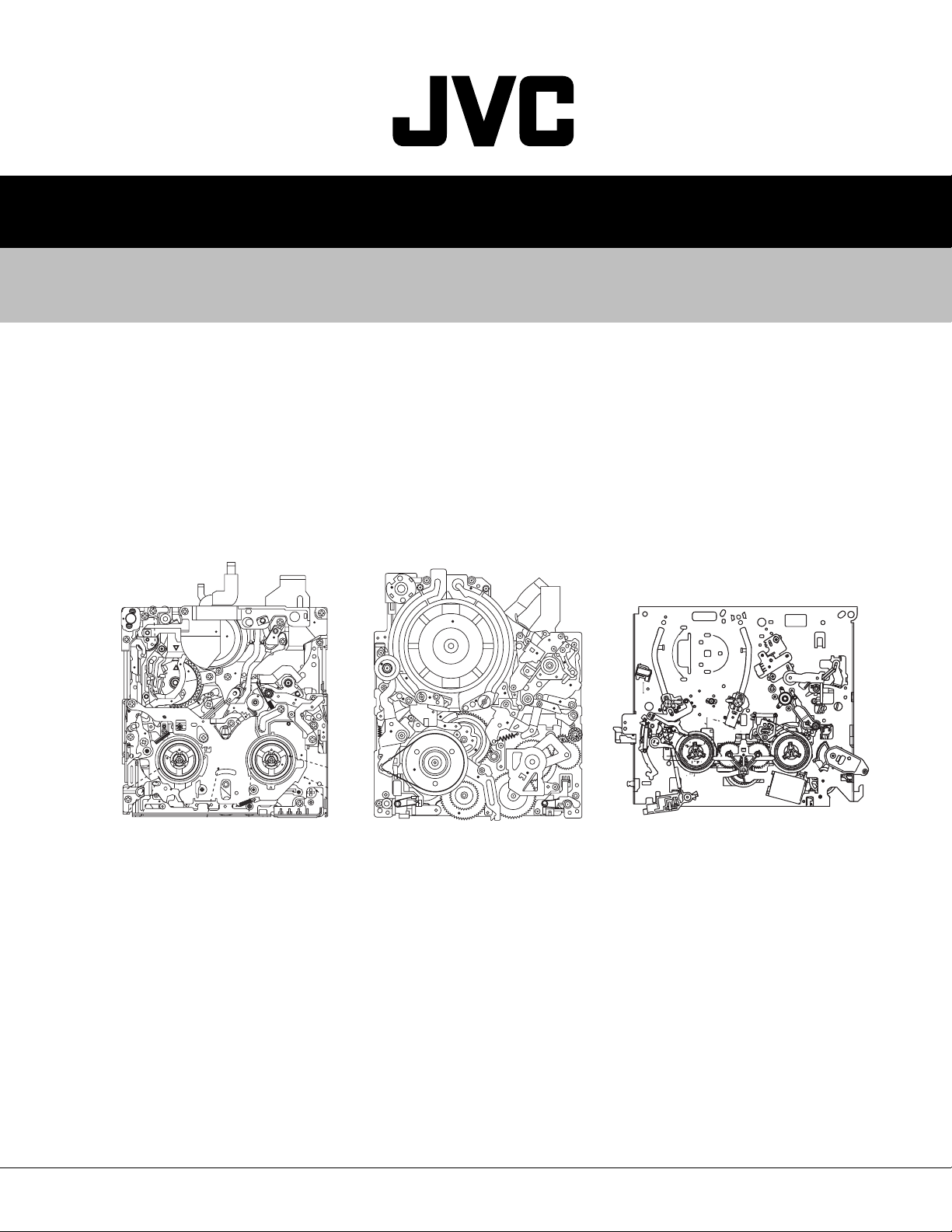
SERVICE MANUAL
MECHANISM ASSEMBLY
DVC MECHANISM
VHS-C MECHANISM
VHS MECHANISM
<DVC MECHANISM> <VHS MECHANISM><VHS-C MECHANISM>
TABLE OF CONTENTS
1 JIGS AND TOOLS . . . . . . . . . . . . . . . . . . . . . . . . . . . . . . . . . . . . . . . . . . . . . . . . . . . . . . . . . . . . . . . . . . . . . 1-1
2 SPECIFIC SERVICE INSTRUCTIONS . . . . . . . . . . . . . . . . . . . . . . . . . . . . . . . . . . . . . . . . . . . . . . . . . . . . . . 2-1
3 PARTS LIST . . . . . . . . . . . . . . . . . . . . . . . . . . . . . . . . . . . . . . . . . . . . . . . . . . . . . . . . . . . . . . . . . . . . . . . . . . 3-1
COPYRIGHT © 2003 VICTOR COMPANY OF JAPAN, LTD.
No.86700
2003/04
Page 2

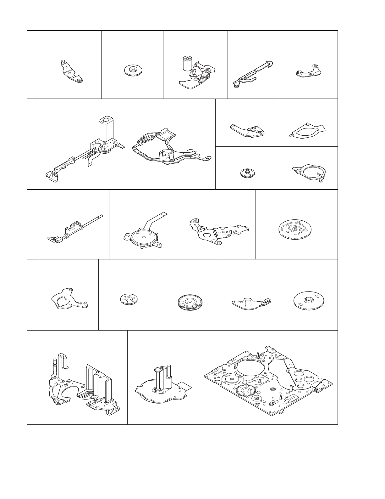
1.1 TOOLS REQUIRED FOR ADJUSTMENTS
1.
3.
5. 6.
Torque driver
YTU94088
Tweezers
P-895
Slit washer installation jig
YTU94121A
2.
Chip IC replacement jig
4.
Bit
YTU94088-003
PTS40844-2
Cleaning cloth
KSMM-01
SECTION 1
JIGS AND TOOLS
1. Torque driver
Be sure to use to fastening the mechanism and exterior parts
because those parts must strictly be controlled for tightening
torque.
Torque setting value of torque driver is limited. At the values
over the maximum torque setting value, fasten a screw
manually not to damage the screw thread.
2. Bit
This bit is slightly longer than those set in conventional torque
drivers.
3. Tweezers
To be used for removing and installing parts and wires.
4. Chip IC replacement jig
To be used for replacement of part.
5. Slit washer installation jig
To be used to install slit washers.
6. Cleaning cloth
Recommended cleaning cloth to wipe down the video heads,
mechanism (tape transport system), optical lens surface.
Fig.1-1-1
1-1 (No.86700)
Page 3

SECTION 2
SPECIFIC SERVICE INSTRUCTIONS
2.1 DVC MECHANISM
2.1.1 Precautions
(1) When fastening parts, pay careful attention to the tighten-
ing torque of each screw. Unless otherwise specified, tighten a screw with the torque of 0.055 N•m (0.56 kgf•cm).
(2) Be sure to disconnect the set from the power supply before
fastening and soldering parts.
(3) When disconnecting/connecting wires, be careful not to get
them and their connectors damaged.
(4) When replacing parts, be very careful neither to damage
other parts nor to fit wrong parts by mistake.
2.1.2 Notes on procedure for disassembly/assembly
The disassembling procedure table (Fig. 2-1-10 on page 2-4,a
part of the table is shown below for reference)shows the procedure to disassemble/reassemble mechanism parts.
Carefully read the following explanation before starting actual
disassembling/reassembling work. The item numbers(circled
numbers)in the following explanation correspond to those appearing under respective columns of the table.
Example
NO. PART NAME FIG. POINT NOTE REMARKS
[1]
[2]
[3]
[4]
[5]
[6]
*1 *2 *3 *4 *5 *6 *7
*1 Numbers appearing in this column indicate the order to re-
move parts. When reassembling, follow these numbers in
the reverse order. Circled numbers in this column correspond to those appearing in drawings of this section.
*2 This column shows part names corresponding to numbers
in the left column.
*3 The symbol (T or B)appearing in this column shows the
side which the objective part is mounted on.
T =the upper side, B =the lower side
*4 Symbols appearing in this column indicate drawing num-
bers.
*5 This column indicates parts and points such as screws,
washers,springs,and others to be removed/fitted for disassembling/reassembling the mechanism. Besides such the
parts, this column occasionally indicates working points.
P= Spring
W= Washer
S= Screw
* = Lock (L),soldering (SD),shield,connector (CN),etc.
Example
CASSETTE HOUSING ASSY T Fig.2-4-3 3(S1),(L1a)-(L1e)
UPPER BASE ASSY T Fig.2-4-4 (S2),(L2a),(L2b)
DRUM ASSY T (S3a),2(S3b)
REEL DISK ASSY(SUP) T Fig.2-4-5 (W4)
REEL DISK ASSY(TU) T
REEL COVER ASSY T
• Remove (W1)=Washer W1.
• Remove the solder at (SD1)=Point SD1.
• Disconnect A = Connector A.
(W5a),(W5b),(W5c)
(W6),(S6a),2(S6b)
*6 Numbers in this column represent the numbers of notes in
the text.
(For parts that need phase adjustment after reassembling,
refer to “MECHANISM ADJUSTMENTS”.)
*7 This column indicates required after-disassembling/-reas-
sembling work such as phase adjustment or mechanism
adjustment.
NOTE 1 a,b,c,d
NOTE 2
NOTE 3 a,b
NOTE 4 a
NOTE 5 a,b
NOTE 6
ADJUSTMENT
ADJUSTMENT
(No.86700)2-1
Page 4
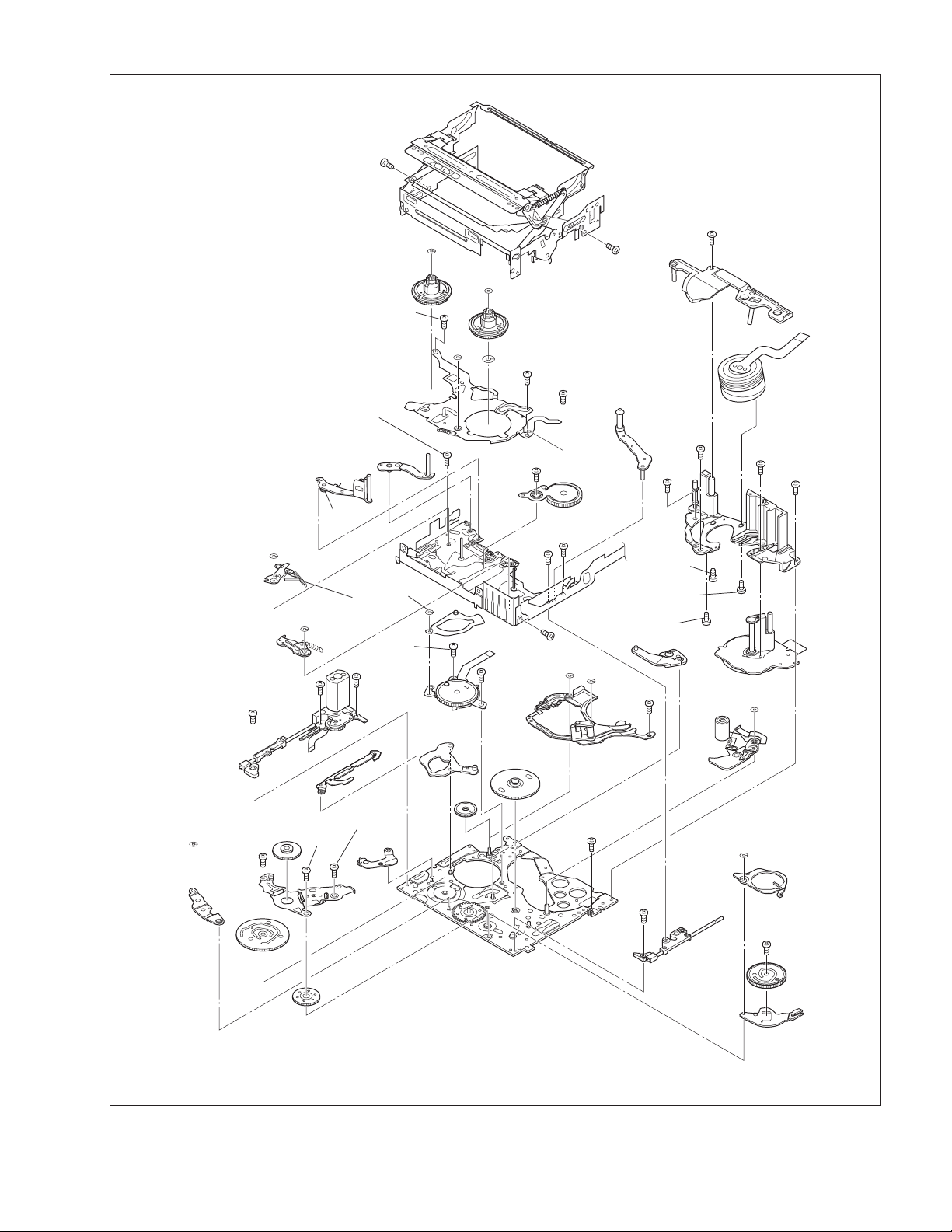
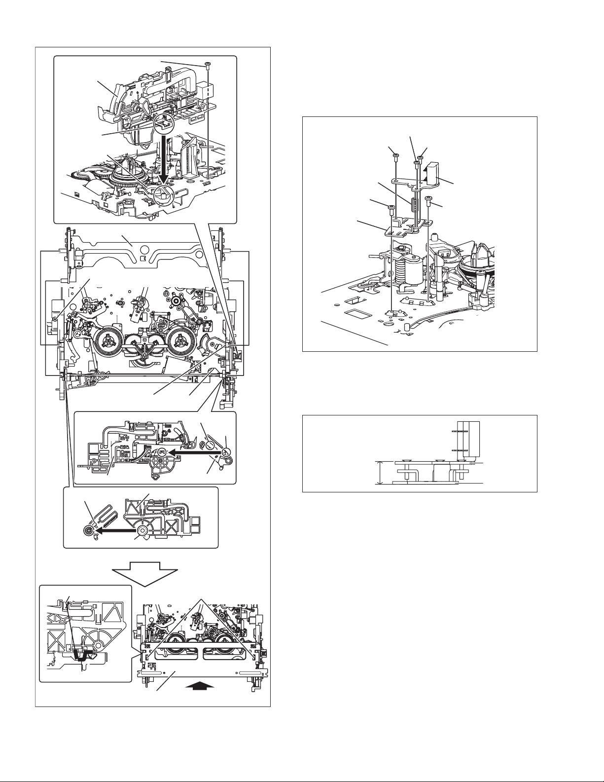
2.1.3 DISASSEMBLY AND ASSEMBLY OF MECHANISM ASSEMBLY
2.1.3.1 General statement
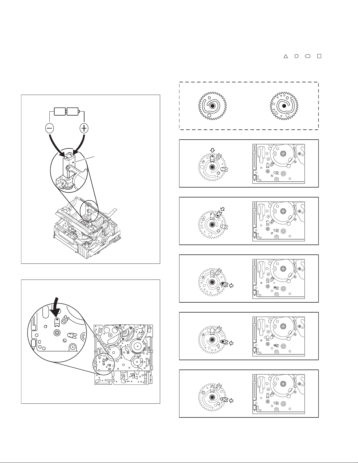
The mechanism should generally be disassembled/assembled in
the C.IN mode (ASSEMBLY mode). (Refer to Fig. 2-1-1,2-1-2.)
However, when the mechanism is removed from the main body,
it is set in the STOP mode. Therefore, after the mechanism is removed from the main body, supply 3 V DC to the electrode on the
top of the loading motor to enter the mechanism mode into the C
IN mode compulsory.
<Mechanism assembly/Cassette housing assembly>
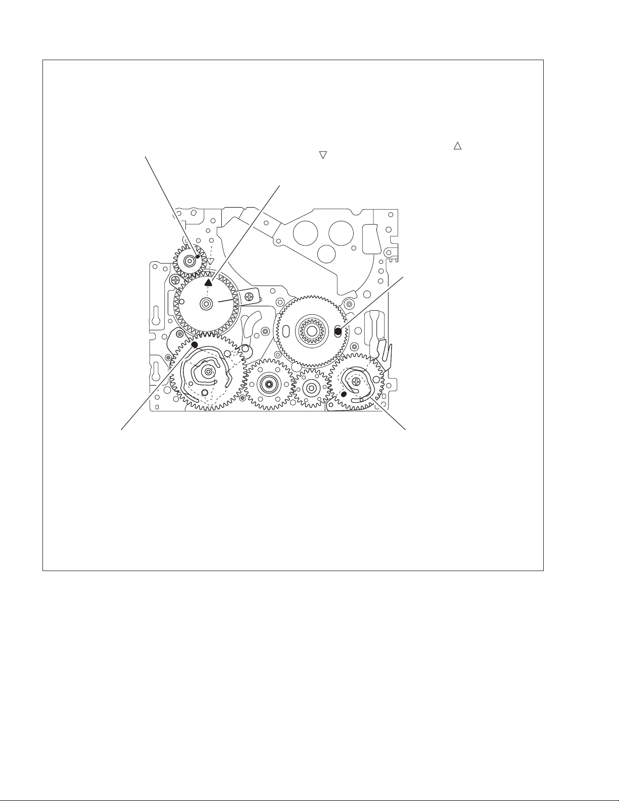
2.1.3.2 Explanation of mechanism mode
The mechanism mode of this model is classified into five modes
as shown in Fig. 2-1-9. Each mechanism mode can be distinguished from others by the relative position of “ ”, “ ”, “ ”, “ ”
marks on the sub cam gear to the inner or outer protrusion on the
main deck.
Refer to Fig. 2-1-3 to 2-1-8 below.
DC3V
LOADING MOTOR
<SUB CAM GEAR>
TOP VIEW BOTTOM VIEW
Fig.2-1-3
<C IN mode>
Fig.2-1-4
Fig.2-1-1
<Back side of the mechanism assembly>
C IN mode
<SHORT FWD mode>
Fig.2-1-5
<STOP mode>
Fig.2-1-6
<REV mode>
Fig.2-1-7
2-2 (No.86700)
<PLAY mode>
Back side of deck
Fig.2-1-2
Fig.2-1-8
Page 5
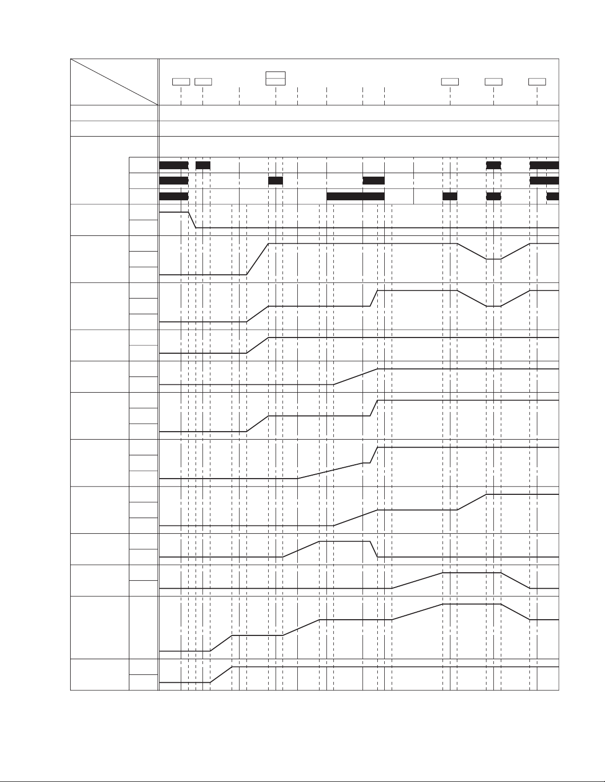
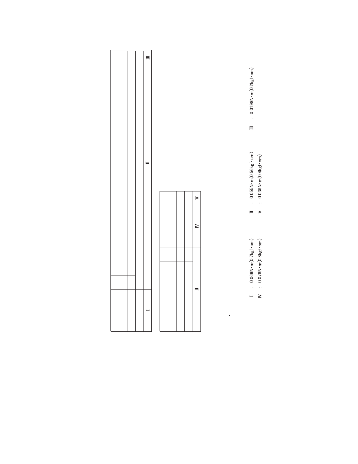
2.1.3.3 Mechanism timing chart
PARTS
MAIN CAM
SUB CAM
ROTARY
ENCODER
EJECT LEVER
TENSION ARM
PAD ARM
TU ARM
SLIDE DECK
SUP. L. ARM
TU. L. ARM
P. ROLLER
BRAKE (S)
BRAKE (T)
MODE
a
b
c
ON
OFF
L. END
LOCK
UL
L. END
OFF
UL
ON
OFF
LOAD
UL
L. END
LOAD
UL
L. END
LOAD
UL
PRESS
LOAD
UL
ON
OFF
ON
OFF
R
SHORT
o
68
o
0
o
0
o
0
o
RELEASE
(30.71o) (95.14o) (110.06o) (206.06o) (210.05o)80.34
(27.14o) (84.08o) (97.35o) (182.10o) (185.63o)71
EJECT
C IN
-12.40o (22.44o) (69.53o) (80.5o) (150.58o) (153.5o)58.71
o
-16.97
o
-15
-13o-3o3
o
74
o
o
o
TU. P. B
START
SLIDE
START
TU. P. B
END
SLIDE
END
STOP PLAYREVFWD
177.79
243.29
o
215
212o218
o
o
o
o
212.77
o
291.16
o
257.3
254.3o260.3
o
243.94
333.82
o
295
292o310
o
o
o
CTL PLATE
RELEASE
LEVER
C
L
ON
OFF
Fig.2-1-9
(No.86700)2-3
Page 6

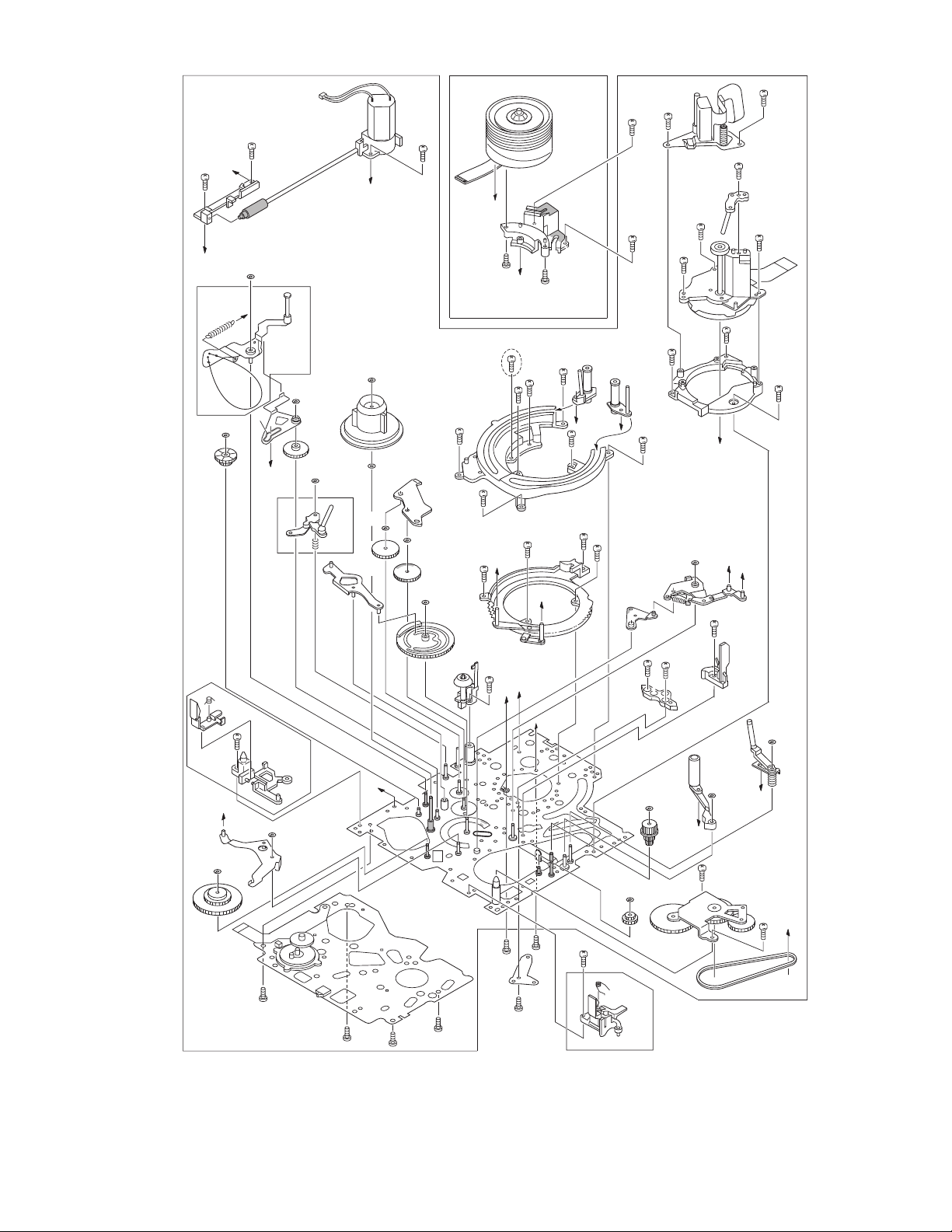
2.1.4 DISASSEMBLY PROCEDURE TABLE
MARK: # After assembly, perform adjustments.
NO. PART NAME
[1]
[2]
[3]
[4]
[5]
[6]
[7]
[8]
[9]
[10]
[11]
[12]
[13]
[14]
[15]
[16]
[17]
[18]
[19]
[20]
[21]
[22]
[23]
[24]
[25]
[26]
[27]
[28]
[29]
[30]
[31]
[32]
[33]
[34]
[35] / [36]
[36]
[37]
CASSETTE HOUSING ASSY
UPPER BASE ASSY
DRUM ASSY
REEL DISK ASSY(SUP)
REEL DISK ASSY(TU)
REEL COVER ASSY
TENSION ARM ASSY
SLANT POLE ARM ASSY
TU ARM ASSY
SWING ARM ASSY
SLIDE DECK ASSY
PAD ARM ASSY
TU BRAKE ASSY
TENSION CTL LEVER ASSY
CENTER GEAR
PINCH ROLLER ARM F. ASSY
TENSION CTL PLATE ASSY
BRAKE CTL LEVER ASSY
MOTOR BRACKET ASSY
GUIDE RAIL ASSY
SLIDE LEVER 2 ASSY
LOADING PLATE ASSY
MODE GEAR
EJECT LEVER
BASE R ASSY
ROTARY ENCODER
GEAR COVER ASSY
MAIN CAM ASSY
SLIDE ARM ASSY
CONNECT GEAR 2
SUB CAM ASSY
CONTROL ARM ASSY
REEL GEAR 1
DRUM BASE ASSY/
CAPSTAN MOTOR
CAPSTAN MOTOR
MAIN DECK ASSY
FIG. POINT NOTE REMARKS
T Fig.2-1-14
T Fig.2-1-15
T
T Fig.2-1-16
T
T
T Fig.2-1-17
T
T
T
T Fig.2-1-18
3(S1),(L1a)-(L1e)
(S2),(L2a),(L2b)
(S3a),2(S3b)
(W4)
(W5a),(W5b)
(W6),2(S6a),(S6b)
(L7)
(P8)
(L9)
(S10)
2(S11a),(S11b),2(L11a),
NOTE 1 a,b,c,d
NOTE 2
NOTE 3 a,b
NOTE 4
NOTE 5 a,b
NOTE 6
NOTE 7
NOTE 8
NOTE 9
NOTE 10
NOTE 11a,b
2(L11b),(L11c)
T Fig.2-1-19
T
T Fig.2-1-20
T
T
T
T
T Fig.2-1-21
T
T
T
T
T
T Fig.2-1-22
T
T
T
T Fig.2-1-23
T
T
T
T
T Fig.2-1-24
T
T
(P12),(L12),(W12)
(P14),(L14),(W14)
(W15)
(W17)
-
3(S20),(L20a),2(L20b)
2(W21),(S21),2(L21a),(L21b)
(W23)
(W25)
(S26a),(S26b),2(L26)
2(S27)
(S28a),2(S28b)
-
-
(S32)
-
3(S35)
(S36)
-
Fig.2-1-10
NOTE 12
-
NOTE 14
NOTE 15
NOTE 16
NOTE 17
NOTE 18
NOTE 19
NOTE 20
NOTE 21
NOTE 22
NOTE 23
NOTE 24
NOTE 25
NOTE 26
NOTE 27
-
NOTE 29
NOTE 30
NOTE 31
NOTE 32
NOTE 33
NOTE 34
NOTE 35a,b
NOTE 36
-
ADJUSTMENT
ADJUSTMENT
ADJUSTMENT / #
ADJUSTMENT
ADJUSTMENT
ADJUSTMENT
ADJUSTMENT / #
ADJUSTMENT / #
ADJUSTMENT
ADJUSTMENT
ADJUSTMENT
ADJUSTMENT
ADJUSTMENT
ADJUSTMENT
ADJUSTMENT
ADJUSTMENT / #
ADJUSTMENT
ADJUSTMENT
ADJUSTMENT
PHASE ADJUSTMENT
PHASE ADJUSTMENT
ADJUSTMENT
PHASE ADJUSTMENT
ADJUSTMENT
ADJUSTMENT
ADJUSTMENT
2-4 (No.86700)
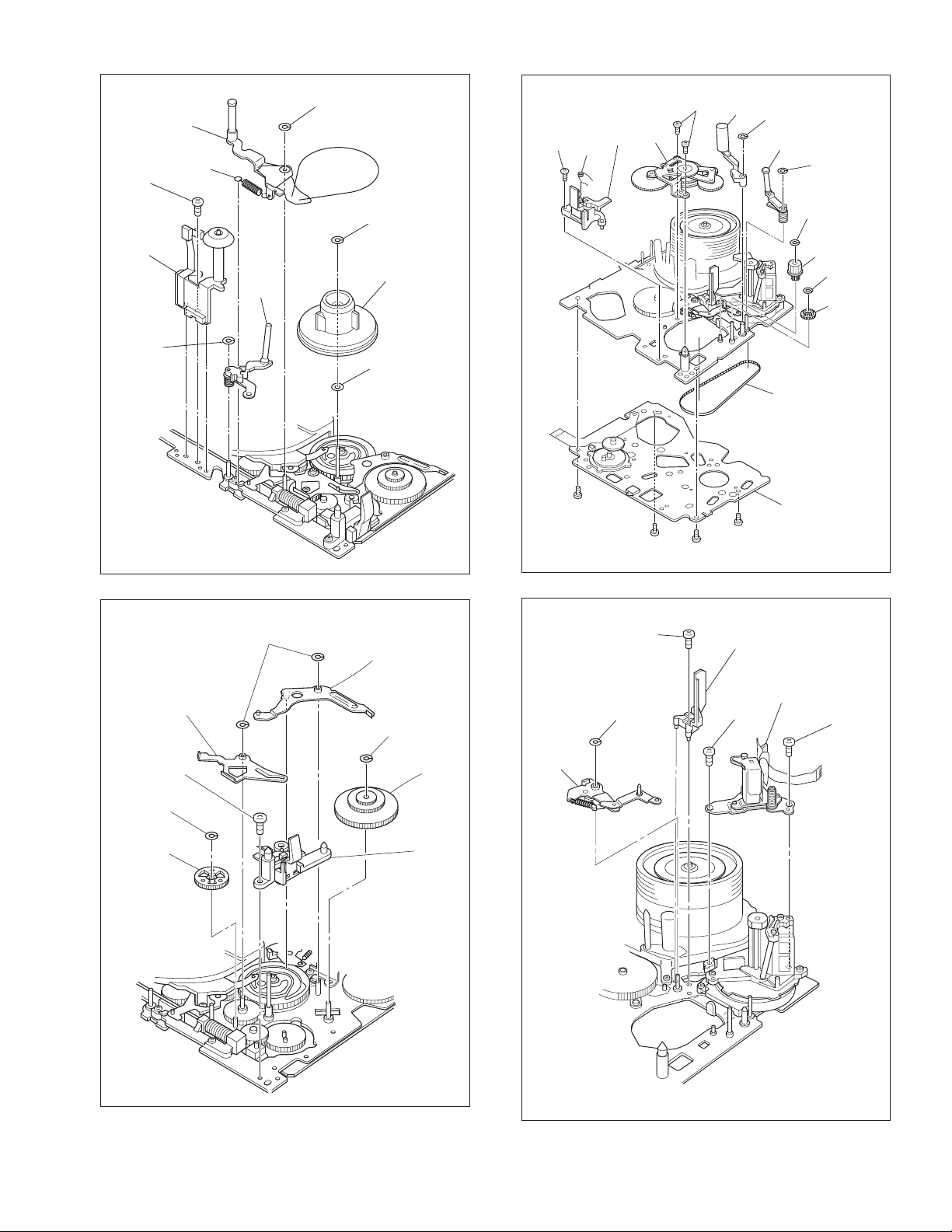
Page 7
2
(S1)
[1]
17
(S20)
(W12)
[14]
(S20)
[20]
16
[12]
[8]
(P8)
(W14)
(P14)
14
(S11b)
(P12)
(S20)
15
(W4)
[4]
(S6a)
[6]
[7]
(W23)
21
(S27)
[18]
27
[35]
7
5
28
(S35)
[17]
4
(S2)
[36]
[2]
(S36)
(W17)
[3]
30
29
(S35)
1
(S1)
(W5a)
8
(W6)
[27]
[30]
[23]
(W5b)
11
(S10)
22
(S27)
[5]
10
(S6b)
13
(S11a)
3
(S1)
[34]
9
(S6a)
[10]
(S11a)
[11]
(W21)
12
[22]
(W21)
(S21)
[21]
[9]
(S35)
(S3b)
(S3a)
6
(S3b)
18
(W15)
(S28b)
[15]
24
[29]
[16]
[31]
25
(S28b)
[28]
23
(S28a)
[19]
[24]
[37]
Fig.2-1-11
20
(S26b)
(W25)
[25]
19
(S26a)
26
(S32)
[26]
[32]
[33]
(No.86700)2-5
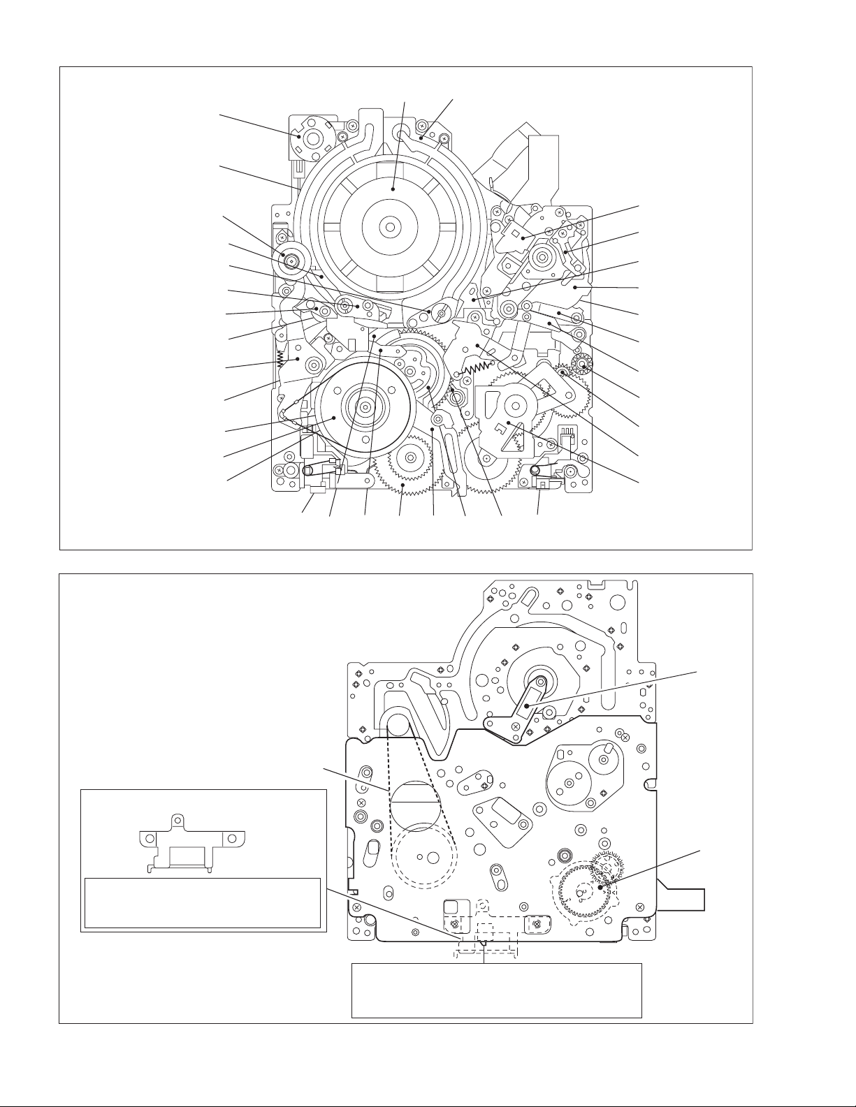
Page 8
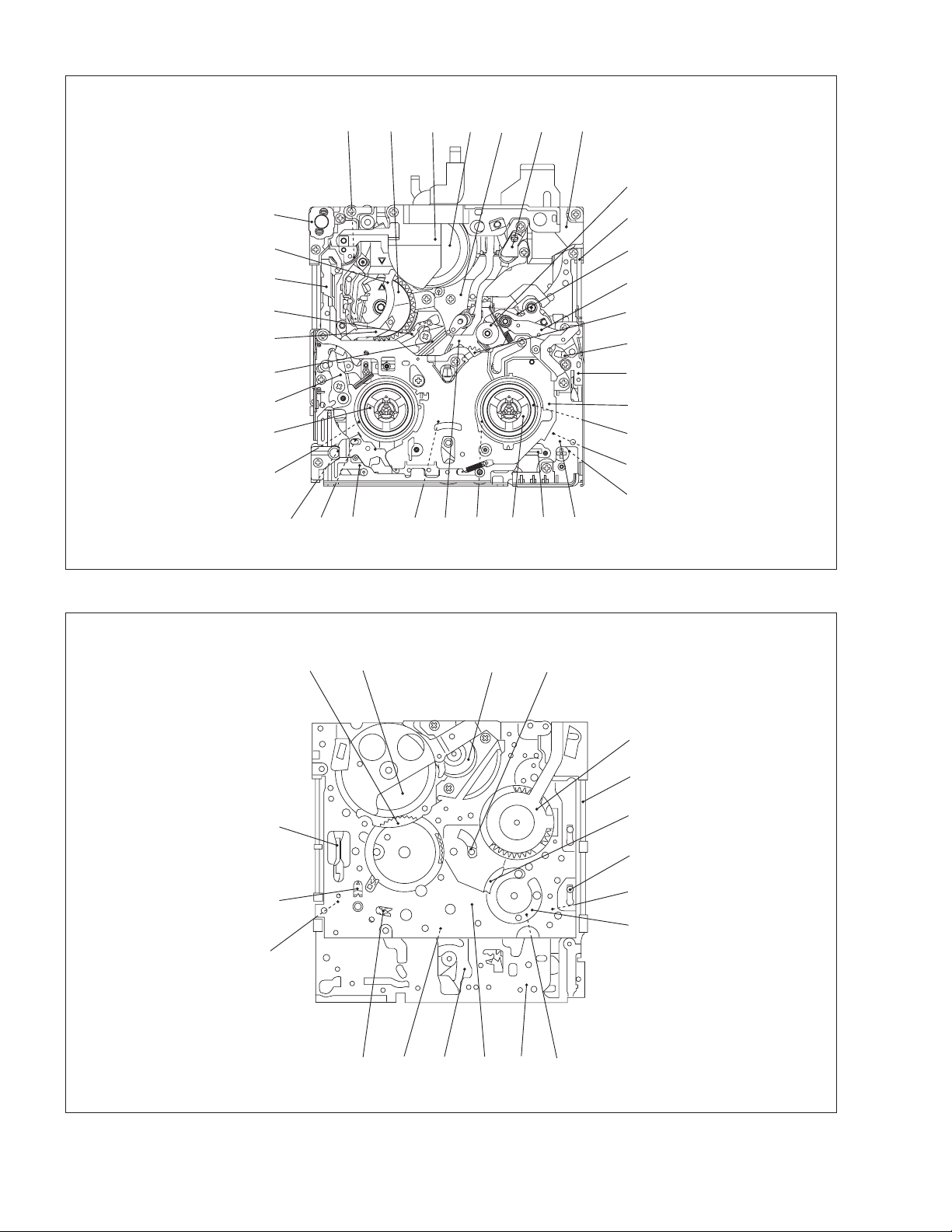
< TOP VIEW >
[24] [27] [ 2 ] [ 3 ] [36] [35][21]
[17]
< BOTTOM VIEW >
[20]
[23]
[18]
[8]
[7]
[22]
[12]
[4]
[29]
[19]
[34]
[14][31][28][16][15][30]
[5]
Fig.2-1-12
[36] [3] [22]
[26]
[34]
[9]
[10]
[33]
[26]
[6]
[37]
[25]
[32]
[11]
[26]
[32]
[25]
[31] [16] [6]
Fig.2-1-13
[37]
[11]
[27]
[20]
[30]
[18]
[19]
[29]
[30]
2-6 (No.86700)
Page 9
2.1.5 DISASSEMBLY/ASSEMBLY
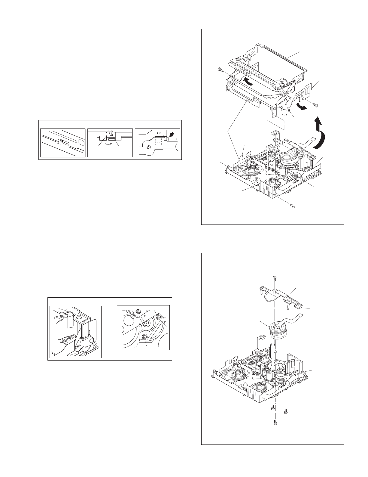
2.1.5.1 [ 1 ] CASSETTE HOUSING ASSY
NOTE 1a:
Be careful not to damage any of the parts during work.
NOTE 1b:
Special care is required in mounting.
NOTE 1c:
When mounting, the CASSETTE HOUSING ASSY should be
attached in the Eject status. Pay heed to the positions of the
LOCK LEVER and EJECT LEVER during mounting.
NOTE 1d:
When mounting, be sure to locate the FPC in the gap.
NOTE 1b
NOTE 1c
EJECT
LEVER
LOCK
LEVER
NOTE 1d
*
2
(S1)
NOTE 1b
(L1d)
(L1c)
(L1b)
NOTE 1a
[1]
LOCK
LEVER
NOTE 1c
NOTE1d
*
1
(S1)
NOTE 1d
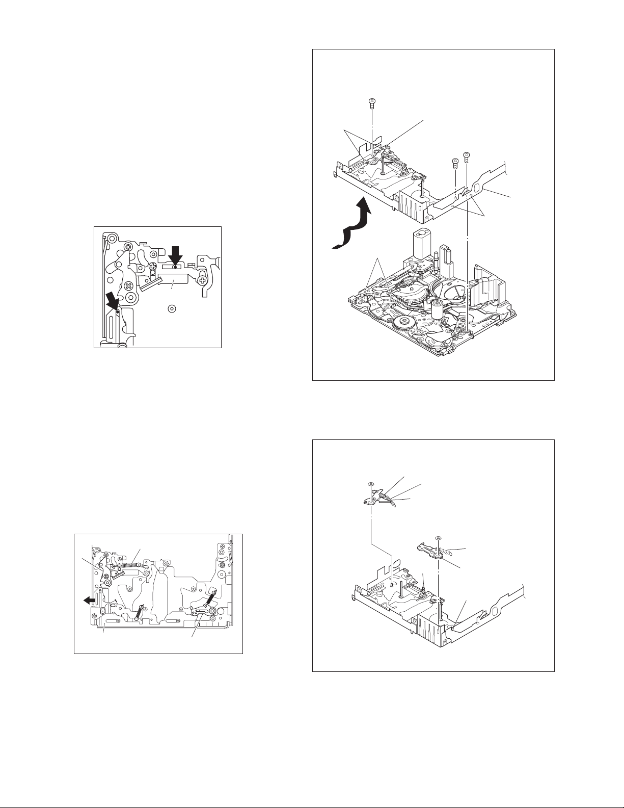
2.1.5.2 [ 2 ] UPPER BASE ASSY
[ 3 ] DRUM ASSY
NOTE 2:
When mounting, be sure to insert the FPC reinforcing sheet.
NOTE 3a:
Be mindful of scratches or damage during work.
NOTE 3b:
Be careful not to attach screws incorrectly.
NOTE 2
NOTE 3b
5
7
6
(L1e)
* 0.069 N.m (0.7 kgf.cm)
Fig.2-1-14
NOTE 3a
[3]
4
(S2)
3
(S1)
(L1a)
*
[2]
NOTE 2
(L2b)
6
(S3b)
7
(S3b)
Fig.2-1-15
(L2a)
NOTE 2
5
(S3a)
NOTE 3b
(No.86700)2-7
Page 10
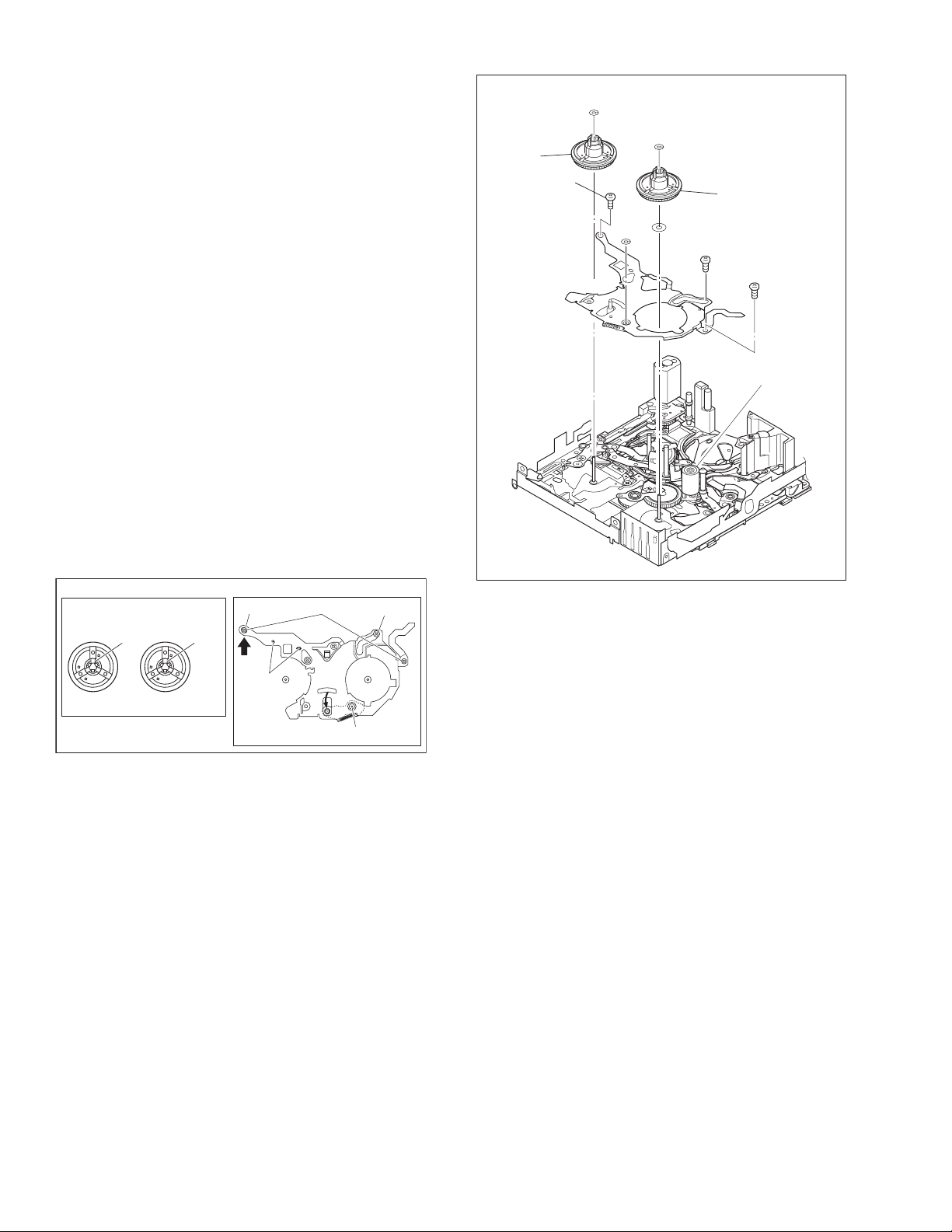
2.1.5.3 [ 4 ] REEL DISK ASSY(SUP)
[ 5 ] REEL DISK ASSY(TU)
[ 6 ] REEL COVER ASSY
NOTE 4:
Be careful not to attach the REEL DISK wrongly. The Supply
side can be identified by the white color at the center.
NOTE 5a:
Be careful not to attach the REEL DISK wrongly. The Take-up
side can be identified by the black color at the center.
NOTE 5b
The washer is inserted under the REEL DISK.
Be carefull not to lose the washer.
Two washers are inserted under the REEL DISK in some products manufactured earlier, but one washer is inserted in the
products manufactured recently and in the future.
See the parts list, and use the parts written in the parts list.
NOTE 6:
Perform the following steps for mounting.
(1) Align the hole with the pin.
(2) Attach the [17] PINCH ROLLER ARM FINAL ASSY by
aligning the positions.
(3) Attach the SLIDE DECK ASSY (POINT[A]) by aligning
the positions.
(4) Check that the parts below them are located in the cor-
rect positions.
(5) Tighten the 2 screws.
(6) Tighten the screw.
(7) Attach the 1 SLIT WASHER parts.
NOTE 4
[4]
[6]
NOTE 6
8
(S6a)
(W4)
(W6)
(W5a)
(W5b)
NOTE 5a
[5]
NOTE 5b
10
(S6b)
9
(S6a)
[17]
NOTE 4, 5
REEL DISK ASSY
WHITE
SUP
TU
BLACK
NOTE 6
(3)
[A]
(4)
(5)
Fig.2-1-16
(2),(6)
(1), (7)
2-8 (No.86700)
Page 11
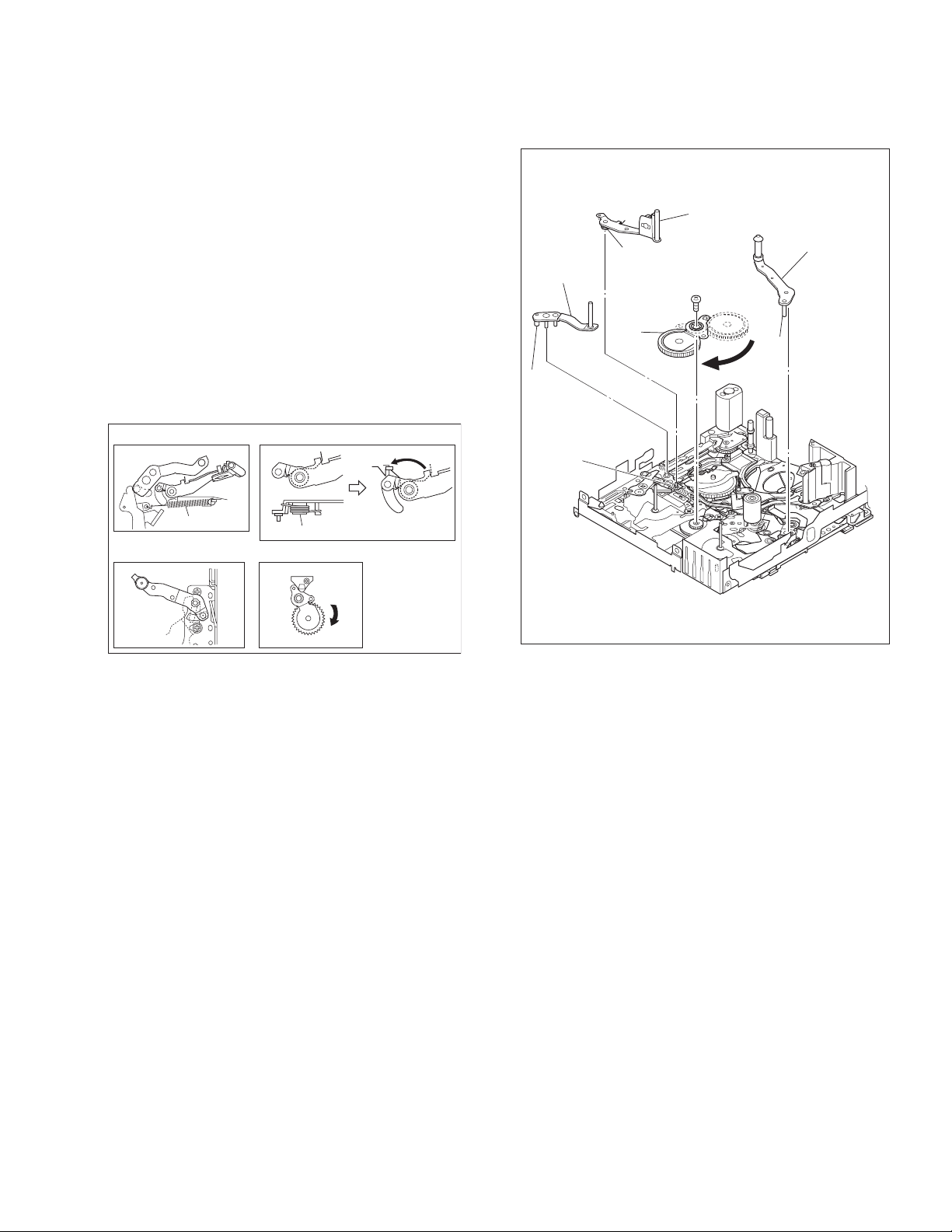
2.1.5.4 [ 7 ] TENSION ARM ASSY
[ 8 ] SLANT POLE ARM ASSY
[ 9 ] TU ARM ASSY
[10] SWING ARM ASSY
NOTE 7:
When detaching, remove the spring of the [12] PAD ARM
ASSY in advance.
Pay attention to the attachment position.
NOTE 8:
When mounting the SLANT POLE ARM ASSY, hook the
spring onto the lug as in diagram A, and fit the combination
onto the SLIDE DECK ASSY. After fitting, hook the spring onto
the lug of the SLIDE DECK ASSY as in diagram B.
Be careful not to lose the spring.
NOTE 9:
Pay attention to the attachment position.
NOTE 10:
When detaching, remove the screw then remove the SWING
ARM ASSY by pulling it up and turning it.
NOTE 7
(L7)
[7]
(P8)
NOTE 8
NOTE 10
[10]
[8]
NOTE 9
[9]
11
(S10)
(L9)
NOTE 7
NOTE 9
SPRING
NOTE 8
AB
SPRING
NOTE 10
NOTE 7
Fig.2-1-17
(No.86700)2-9
Page 12
2.1.5.5 [11] SLIDE DECK ASSY
NOTE 11a:
Each of the parts on the SLIDE DECK ASSY can be replaced
separately.
When detaching the assembly, if there is no need to replace
any of its parts, remove the SLIDE DECK ASSY as it is.
NOTE 11b:
When mounting, pay attention to the positions of the [22]
SLIDE LEVER 2 ASSY studs and the [19] BRAKE CTL LEVER ASSY.
When mounting, position the CONTROL PLATE on the left
side.
Pay attention to the position of the SLIDE GUIDE PLATE during mounting.
NOTE 11b
SLIDE GUIDE
PLATE
(L11b)
14
(S11b)
NOTE 11b
(L11c)
13
(S11a)
12
(S11a)
NOTE 11a
[11]
(L11a)
2.1.5.6 [12] PAD ARM ASSY
[13] [14] TU BRAKE ASSY
NOTE 12:
The spring may have already been disengaged when the [ 8 ]
SLANT POLE ARM ASSY was removed.
NOTES 14:
When mounting, pay attention to the correct positioning.
Mount the CONTROL PLATE by moving it fully toward the left
side.
NOTE 12,14
[12]
CONTROL
PLATE
SPRING
[14]
(W12)
Fig.2-1-18
[12]
NOTE 12
(P12)
(W14)
(L12)
Fig.2-1-19
(P14)
[14]
NOTE 14
(L14)
2-10 (No.86700)
Page 13
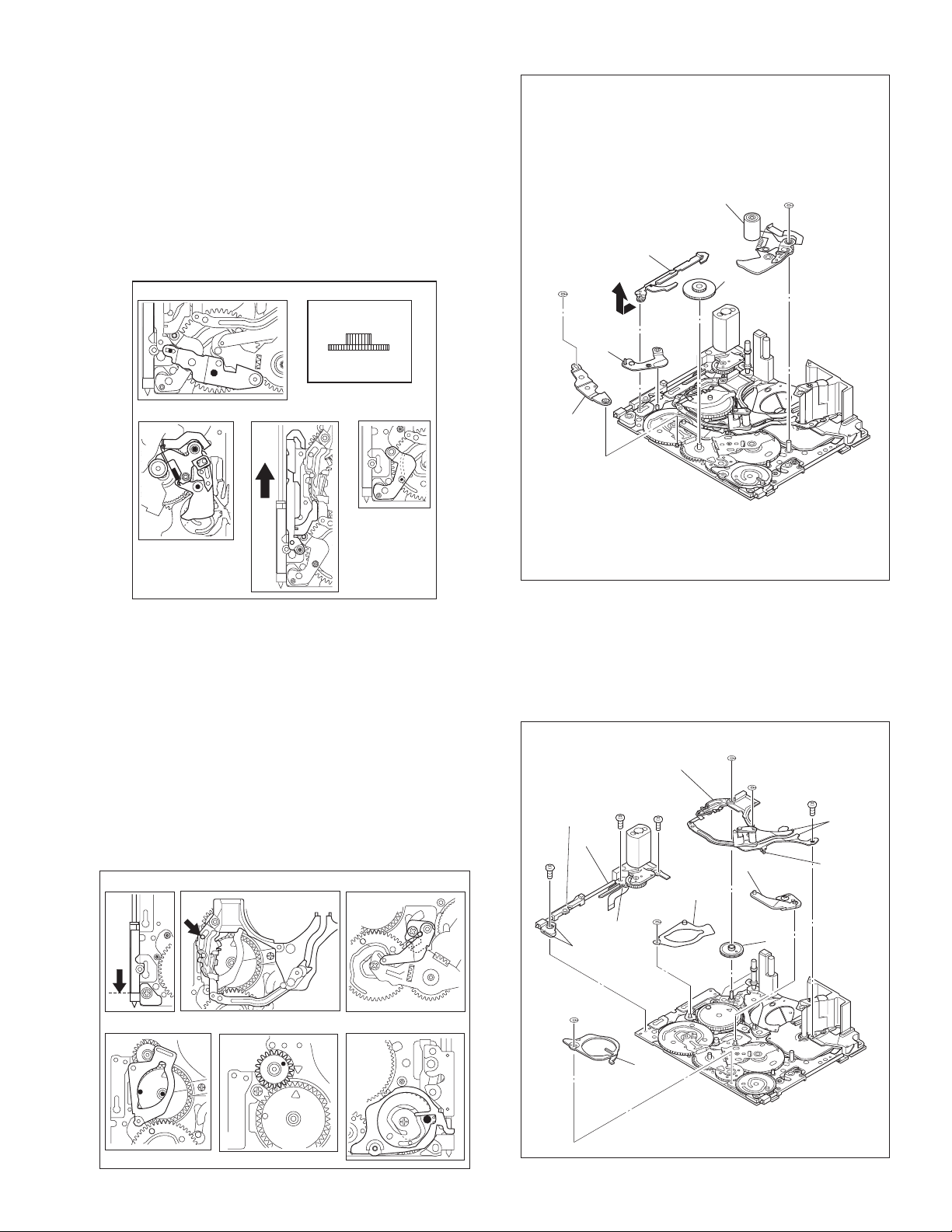
2.1.5.7 [15] TENSION CTL LEVER ASSY
[16] CENTER GEAR
[17] PINCH ROLLER ARM FINAL ASSY
[18] TENSION CTL PLATE ASSY
[19] BRAKE CTL LEVER ASSY
NOTES 15/16:
When mounting, pay attention to the correct positioning.
NOTE 17:
Take care against grease attachment during work.
NOTES 18/19:
When mounting, pay attention to the correct positioning.
NOTE 15
NOTE 16
(TOP)
(BOTTOM)
(W15)
NOTE 18
NOTE 19
[19]
[18]
NOTE 17
[17]
[16]
NOTE 16
(W17)
NOTE 17
2.1.5.8 [20] MOTOR BRACKET ASSY
[21] GUIDE RAIL ASSY
[22] SLIDE LEVER 2 ASSY
[23] LOADING PLATE ASSY
[24] MODE GEAR
[25] EJECT LEVER
NOTE 20:
When mounting, pay attention to the positi oning of the slidi ng
parts.
NOTE 21:
When mounting, take care that no part is allowed to float or rattle.
NOTES 22/23/24/25:
When mounting, pay attention to the correct positioning.
NOTE 20 NOTE 21
NOTE 18
NOTE 19
NOTE 22
[15]
NOTE 15
NOTE 20
17
(S20)
(S20)
[20]
(L20a)
(L20b)
16
Fig.2-1-20
NOTE 21
[21]
15
(S20)
NOTE 23
(W23)
[23]
(W21)
(W21)
[22]
NOTE 24
18
(S21)
(L21a)
(L21b)
NOTE 22
[24]
NOTE 23
NOTE 24
(W25)
NOTE 25
[25]
NOTE 25
Fig.2-1-21
(No.86700)2-11
Page 14
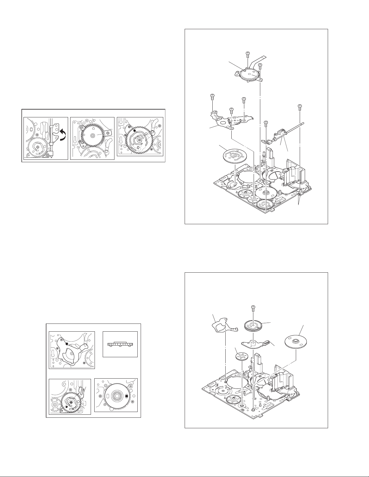
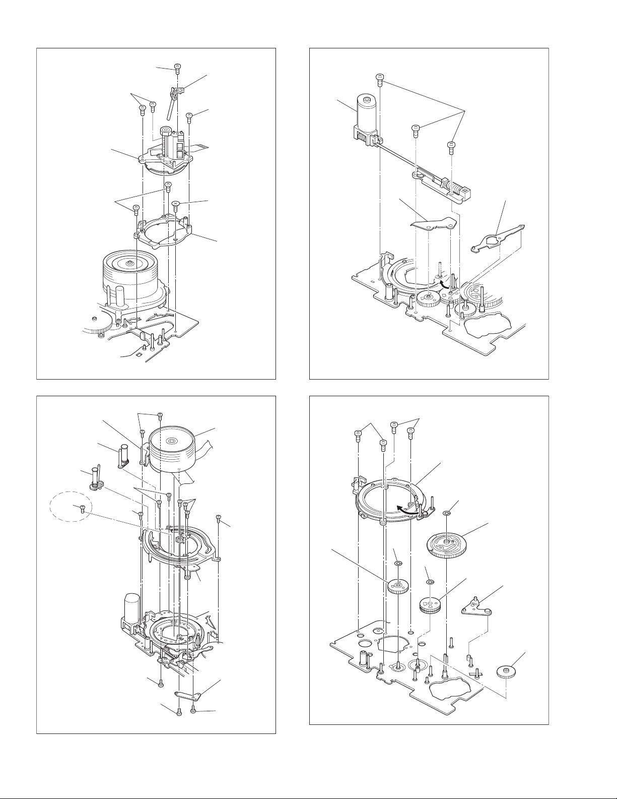
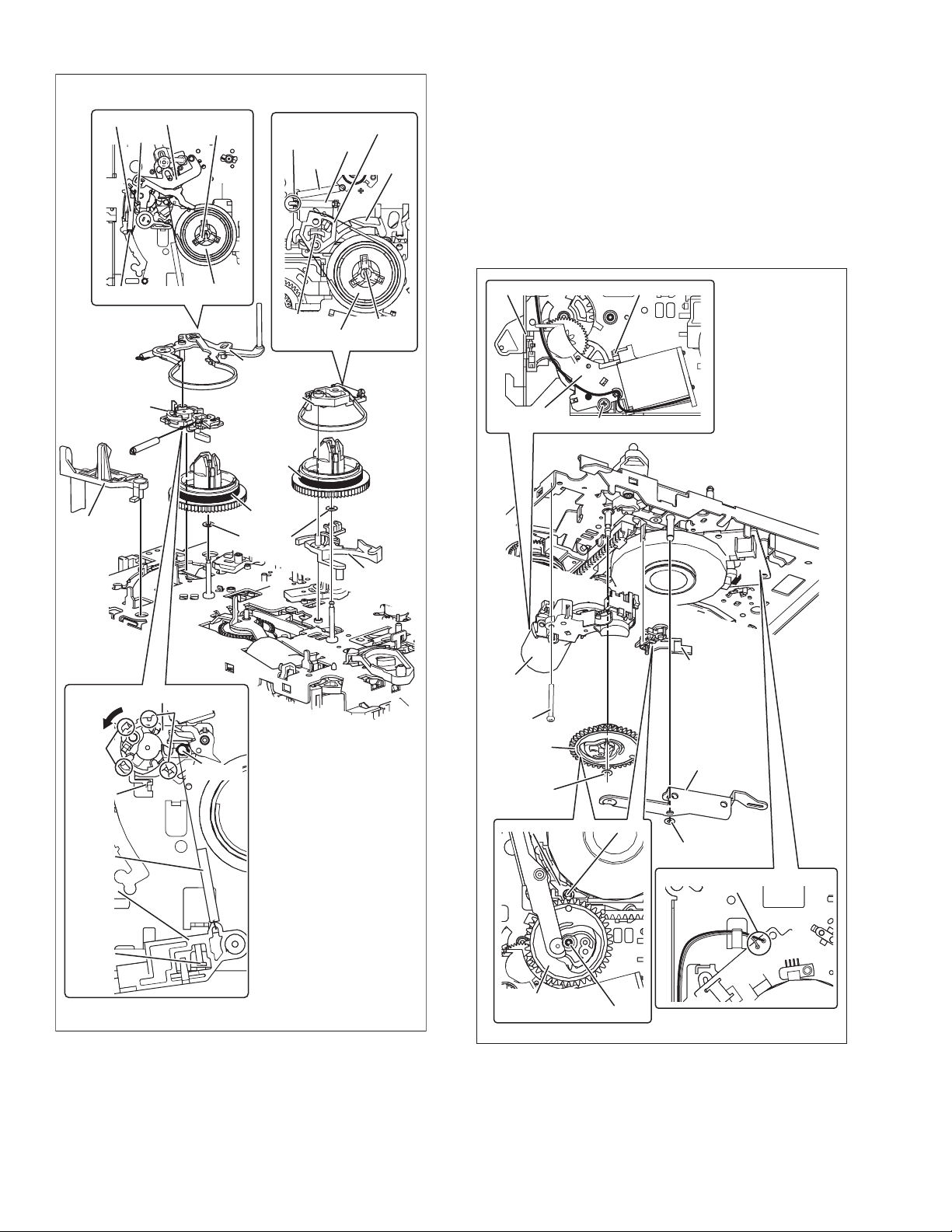
2.1.5.9 [26] BASE R ASSY
[27] ROTARY ENCODER
[28] GEAR COVER ASSY
[29] MAIN CAM ASSY
NOTE 26:
When mounting, fold the sliding part to the inner side.
NOTE 27:
When mounting, pay attention to the correct positioning and
the FPC layout.
NOTE 29:
When mounting, pay attention to the correct positioning.
NOTE 26 NOTE 27 NOTE 29
(S28b)
[28]
NOTE 27
[27]
24
25
(S28b)
21
(S27)
23
(S28a)
22
(S27)
(S26a)
19
*
20
(S26b)
2.1.5.10 [30] SLIDE ARM ASSY
[31] CONNECT GEAR 2
[32] SUB CAM ASSY
[33] CONTROL ARM ASSY
[34] REEL GEAR 1
NOTE 30:
When mounting, pay attention to the correct positioning.
NOTE 31:
When mounting, pay attention to the position of the front and
back.
NOTES 32/33/34:
When mounting, pay attention to the correct positioning.
NOTE 30 NOTE 31
(TOP)
(BOTTOM)
[29]
NOTE 29
* 0.0198N
NOTE 30
[30]
.
m (0.2kgf.cm)
NOTE 31
[31]
Fig.2-1-22
26
(S32)
NOTE 32
[26]
NOTE 26
[32]
[33]
NOTE 33
(L26)
NOTE 34
[34]
NOTE 32/33
2-12 (No.86700)
NOTE 34
[33]
[32]
Fig.2-1-23
Page 15
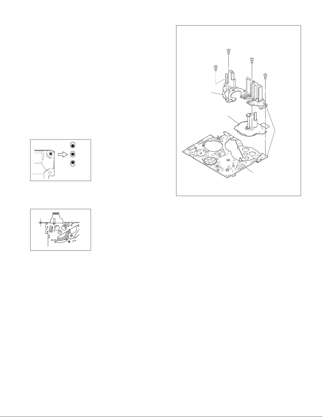
2.1.5.11 [35] DRUM BASE ASSY
[36] CAPSTAN MOTOR
[37] MAIN DECK ASSY
NOTES 35a/36:
Since [36]CAPSTAN MOTOR is attached to [35]DRUM BASE
ASSY, remove [36]CAPSTAN MOTOR together with
[35]DRUM BASE ASSY when removing [36]CAPSTAN MOTOR.
[36]CAPSTAN MOTOR should not be separated from
[35]DRUM BASE ASSY except when replacing them.
NOTE 35b:
It is very important to attach [35]DRUM BASE ASSY to the
proper position.
Especially, improper engagement of [36]CAPSTAN MOTOR
with [34]REEL GEAR 1 causes operational defection or abnormal sound. Therefore, confirm the attachment position before
disassembly procedure.
See the following figure as for the proper attachment position.
NOTE 35b
NG
OK
When [35]DRUM BASE ASSY
is properly attached, the screw
hole tends to be located at the
center of the oval.
NG
When the screw hole is
located far from the center of
the oval, operational defection
or abnormal sound may occur.
*
28
(S35)
*
27
(S35)
[35]
NOTE 35a
[36]
NOTE 36
* 0.078 N.m (0.8 kgf.cm)
** 0.039 N.m (0.4 kgf.cm)
30
(S36)
[37]
**
29
(S35)
*
NOTE 35b
Fig.2-1-24
(A)
Before removing [35]DRUM
BASE ASSY, confirm the
position of [35]DRUM BASE
ASSY by seeing the length
(A), as shown in the left figure.
When reattaching [35]DRUM
BASE ASSY, confirm the
position to reattach [35]DRUM
BASE ASSY by seeing the
length (A). Be sure to reattach
[35]DRUM BASE ASSY to the
same position as it has been
before the removing procedure.
(No.86700)2-13
Page 16
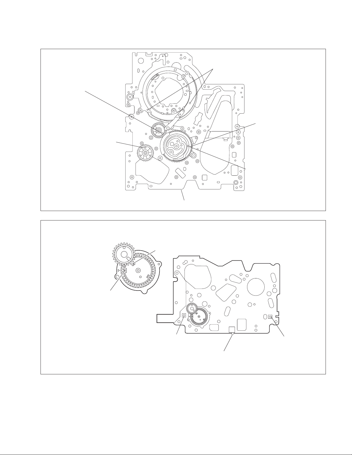
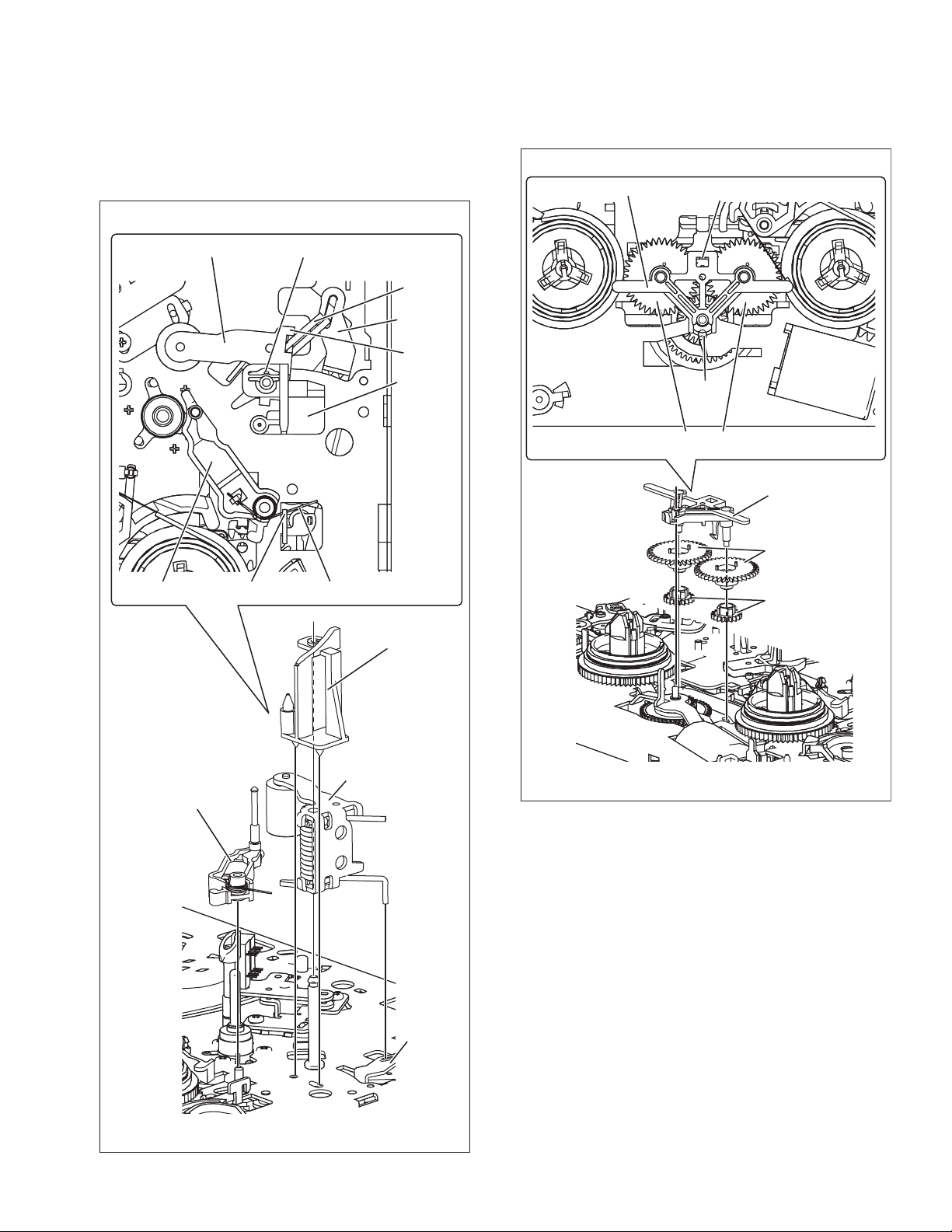
2.1.6 CHECKUP AND ADJUSTMENT OF MECHANISM PHASE
MODE GEAR
[24]
Align the MODE GEAR with the Main Deck
Assembly hole.
Note:
The MODE GEAR may
be displaced during the
mechanism operation,
however it can be
checked from the rear
and realigned during
manual assembly.
[27]
ROTARY ENCODER
Mount the ROTARY ENCODER by aligning its mark ( )
and the mark ( ) of the Main Deck Assembly.
Note:
Be careful when handling the FPC during mounting.
[34]
REEL GEAR 1
Align the REEL GEAR 1 with
the Main Deck Assembly hole.
Note:
The REEL GEAR 1 may be
displaced during mechanism
operation, however this can
be checked from the rear and
realigned during manual
assembly.
[29]
MAIN CAM ASSY/[30]SLIDE ARM ASSY
When mounting the SLIDE ARM ASSY align it with the
Main Deck Assembly and MAIN CAM ASSY holes.
Note:
During the mounting procedure, make sure that the[32]
SUB CAM ASSY is in the correct mounting position.
[32]
Fig.2-1-25
SUB CAM ASSY/[33] CONTROL ARM ASSY
Mount the SUB CAM ASSY hole to align with the CONTROL
ARM ASSY and Main Deck Assembly holes and then tighten
them all together with a screw.
Note:
When mounting it, make sure that the[29]MAIN CAM ASSY is
in the correct mounting position.
2-14 (No.86700)
Page 17
2.1.7 MECHANISM ADJUSTMENTS
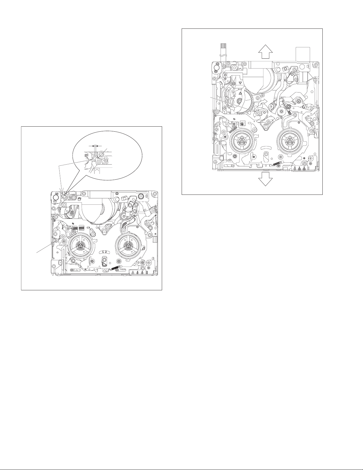
2.1.7.1 Adjustment of the slide guide plate
Use Fig. 2-1-26 as the reference unless otherwise specified.
(1) Set the PLAY mode. See Fig. 2-1-8.
(2) Loosen the screws (A, B).
(3) With the Main Deck and Slide Deck Assemblies pushed into the unit, tighten the screws (A, B) while applying pressure to the
stud (shaft) on the Slide Guide plate.
The pressure applied should be enough to enable utilization of the rebounding force of the springs.
The tightening torque should be 0.069 N•m (0.7 kgf•cm).
(4) Check the operation.
Repeat unloading and loading several times and make sure that these operations can be performed smoothly without producing
rattles.
(3)
(
2)(3
)
SCREW A
(3)
STUD
(SHAFT)
(3)
2)(3
)
(
SCREW B
(3)
(3)
Fig.2-1-26
(No.86700)2-15
Page 18
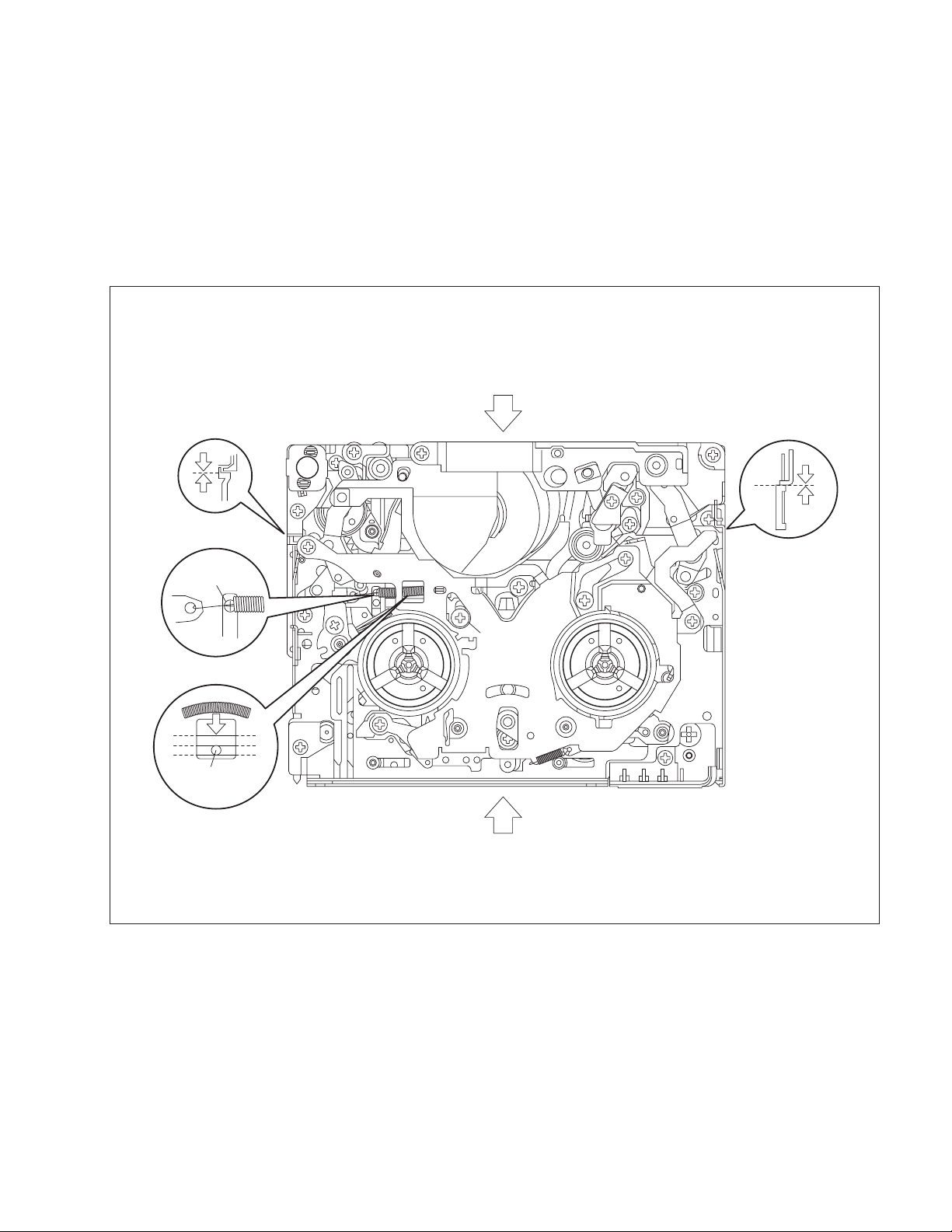
2.1.7.2 Adjustment of the Tension Arm and Pad Arm Assemblies
Use Fig. 2-1-27 as the reference unless otherwise specified.
(1) Set the PLAY mode.
See Fig. 2-1-8.
(2) Loosen the screw A.
(3) With the take-up side at the bottom, align the extreme end
of the Tension Arm Assembly with the crossed grooves on
the screw B that retains the Loading Motor Assembly and
then tighten the screw A.
The tightening torque should be 0.069 N•m (0.7 kgf•cm).
(4) Check the operation.
Repeat unloading and loading several times and make
sure that the Tension Arm Assembly is located within the
normal range.
TENSION
ARM ASSY
SCREW B
(
2)(3
)
SCREW A
Fig.2-1-28
(
(3)
3)
(
2)(3
)
SCREW A
Fig.2-1-27
2.1.7.3 Adjustment of the Slide Lever 2
Use Fig. 2-1-28 as the reference unless otherwise specified.
(1) Set the C IN mode.
See Fig. 2-1-4.
(2) Loosen the screw A.
(3) Set the Main Deck and Slide Deck Assemblies apart so that
they do not rattle, then tighten the screw A by screwing it
fully toward the Drum Assembly.
The tightening torque should be 0.069 N•m (0.7 kgf•cm).
(4) Check the operation.
Repeat unloading and loading several times and make
sure that these operations can be performed smoothly
without producing rattles.
2-16 (No.86700)
Page 19
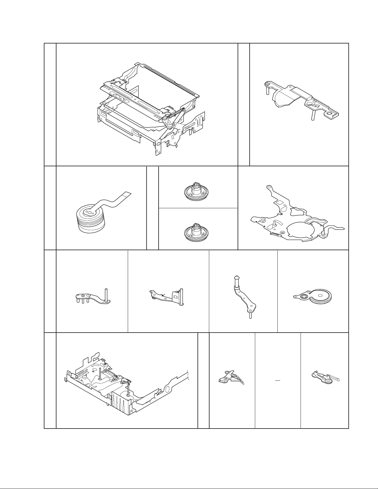
2.1.8 SERVICE NOTE
Use the following chart to manage mechanism parts that are removed for disassembling the mechanism.
[1]
CASSETTE HOUSING ASSY UPPER BASE ASSY
[2]
Fig.2-1-14
[3]
Fig.2-1-15
[7]
DRUM ASSY
TENSION ARM ASSY
Fig.2-1-15
REEL DISK ASSY(SUP)
[4]
Fig.2-1-16
SLANT POLE ARM ASSY SWING ARM ASSYTU ARM ASSY
[ 8 ] [ 9 ] [10]
REEL DISK ASSY(TU)
[5]
REEL COVER ASSY
[6]
Fig.2-1-17
[11]
Fig.2-1-18
SLIDE DECK ASSY
Fig.2-1-19
Fig.2-1-29
PAD ARM
ASSY
[13][12]
TU BRAKE
[14]
ASSY
(No.86700)2-17
Page 20
[15]
Fig.2-1-20
TENSION CTL
LEVER ASSY
CENTER GEAR
[16]
PINCH ROLLER
[17]
ARM F ASSY
TENSION
.
[18]
CTL PLATE
ASSY
[19]
BRAKE CTL
LEVER
ASSY
[20]
Fig.2-1-21Fig.2-1-22Fig.2-1-23Fig.2-1-24
[26]
[30]
MOTOR
BRACKET
ASSY
BASE R ASSY
SLIDE ARM
ASSY
[31]
[21]
ROTAR Y
[27]
ENCODER
CONNECT
GEAR 2
GUIDE
RAIL ASSY
[32]
[28]
SUB CAM
ASSY
[22]
[24]
GEAR COVER
ASSY
[33]
SLIDE LEVER 2
ASSY
MODE GEAR EJECT LEVER
MAIN CAM ASSY
[29]
CONTROL
ARM ASSY
[23]
[25]
[34]
LOADING
PLATE ASSY
REEL GEAR 1
[35]
2-18 (No.86700)
DRUM BASE ASSY
CAPSTAN MOTOR MAIN DECK ASSY
[36]
Fig.2-1-30
[37]
Page 21
2.1.9 SERVICE NOTE
Use the following chart to manage screws.
[22]
21 2215
Symbol No. [1] [2] [3] [6] [10] [11] [20] [21]
Removing order of screw 1 2 3 4 5 6 7 8 9 10 11 12 13 14 15 16 17 18 19 20
Place to stick screw
24
Pay careful attention to tightening t or que for each screw.
[27]
<NOTE>
Symbol No. [28] [32] [35] [36]
Place to stick screw
Screw tightening torque
Removing order of screw 21 22 23 24 25 26 27 28 29 30
Screw tightening torque
Reference drawing (Fig. No.2-1-**) 14 16 17 18
Reference drawing (Fig. No.2-1-**) 22 23
Fig.2-1-31
(No.86700)2-19
Page 22

2.1.10 REMARKS
2.1.10.1 Cleaning
(1) For cleaning of the upper drum (particularly video heads),
use fine-woven cotton cloth with alcohol soaks through. Do
not move the cloth but turn the upper drum counterclock-
wise.
NOTE:
Make sure not to move the cloth in the vertical directi o n
to the video head, since it may cause damage of the video
heads.
(2) For cleaning of parts of the tape transport system except
the upper drum, use fine-woven cotton cloth or cotton swab
soaked alcohol.
(3) After cleaning, confirm that the cleaned parts are complete-
ly dry before loading the deck with cassette tape.
2.1.10.2 Applying oil and grease
(1) Periodical oiling and greasing are not required but should
be done to new parts when replacing. If oil and grease on
the other parts of the other party are old and dirty, wipe
them clean and apply new oil or grease.
(2) For parts and points to apply oil and grease, refer to the ex-
ploded view of the 3.1 DVC MECHANISM ASSEMBLY.
Fig.2-1-32 specifies oil and grease to be used.
(3) When oiling, clean the objective parts with alcohol first and
apply one or two drop(s) of oil. Too much oiling causes ro-
tary parts to slip because of oil leakage.
Classification Part No. Symbol in drawing
Grease KYODO-SH-JB AA
Oil YTU94027 BB
Grease (HANARL)
RX-410R CC
specifies oil and grease to be used
Fig.2-1-32
2-20 (No.86700)
Page 23

2.2 VHS-C MECHANISM
2.2.1 Precautions
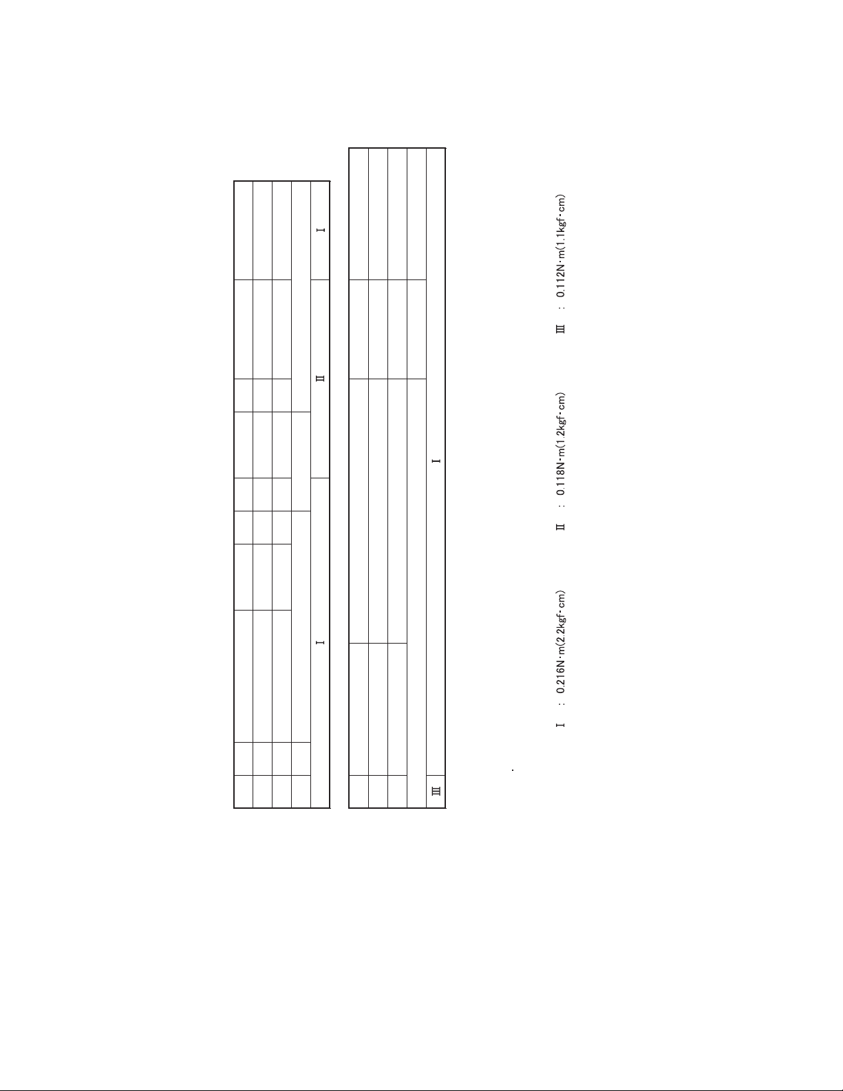
(1) When fastening parts, pay careful attention to the tighten-
ing torque of each screw. Unless otherwise specified, tighten a screw with the torque of 0.216 N•m (2.2 kgf•cm).
Torque setting value of torque driver is limited. At the values over the maximum torque setting value, fasten a screw
manually not to damage the screw thread.
(2) Be sure to disconnect the set from the power supply before
fastening and soldering parts.
(3) When disconnecting/connecting wires, be careful not to get
them and their connectors damaged.
(4) When replacing parts, be very careful neither to damage
other parts nor to fit wrong parts by mistake.
Example
STEP/LOC.
No.
[1]
[2]
[3]
ROLLER BASE ASSEMBLY T M1 (S1) –
TENSION ARM ASSEMBLY T M1 (P1), (W1a) –
REEL DISC (SUP) T M1 (W1a), (W1b) _
PART NAME
*1 *2 *3 *4 *5 *6
FIG.
REMOVAL INSTALLATION
ADJUSTMENT
POINT CONDITION
NOTE
2.2.2 How to read the disassembly and assembly
*1 Order of steps in Procedure
When reassembling, perform the step(s) in the reverse order. These numbers are also used as the identification (lo-
cation) No. of parts Figures.
*2 Part to Name be removed or installed.
*3 Location of part.
T = The Upper side
B = The Lower side
*4 Fig. No. showing Procedure or Part Location.
M = Mechanism
*5 Identification of part to be removed, unhooked, unlocked,
released, unplugged, unclamped or unsoldered.
P= Spring
W= Washer
S= Screw
* = Unhook, unlock, release, unplug or unsolder.
Example
• Remove (W1)=Washer W1.
• Remove the solder at (SD1)=Point SD1.
• Disconnect A = Connector A.
*6 Adjustment information for installation.
(+) = Refer to Exploded Views for Lubrication information.
(No.86700)2-21
Page 24

2.2.3 DISASSEMBLY/ASSEMBLY PROCEDRURE TABLE
This procedure starts with the condition that the cabinet parts and deck parts. Also, all the fo llowing procedures for adjustment and
parts replacement should be performed in STOP mode. When reassembling, perform the step(s) in the reverse order.
REMOVAL INSTALLATION
STEP/LOC.
No.
[1]
[2]
[3]
[4]
[5]
[6]
[7]
[8]
[9]
[10]
[11]
[12]
[13]
[14]
[15]
[16]
[17]
[18]
[19]
[20]
[21]
[22]
[23]
[24]
[25]
[26]
[27]
[28]
[29]
[30]
[31]
[32]
[33]
[34]
[35]
[36]
[37]
PART NAME
ROLLER BASE ASSY T M1 (1) –
TENSION ARM ASSY M1 (P1), (W1a) –
REEL DISC T M1 (W1a), (W1b) –
SLANT ARM ASSY M1 (W1a) –
CANCEL LEVER ASSY M2 (W2) –
EJECT LEVER ASSY M2 (W2) –
CASSETTE GUIDE (LEFT) M2 (2) –
SUPPLY CLUTCH ASSY M2 (W2) –
WHEEL GEAR T M2 (W2) See, Adjustment procedure for
ROTARY ENCODER
TIMING BELT B M3 – –
CENTER PULLEY UNIT T/B M3 2(S3a) –
CASSETTE GUIDE (R) ASSY T M3 (S3b), (P3) (Only use SVHS model)
TAKE UP GEAR T M3 (W3a) –
BRAKE SUB GEAR T M3 (W3a) –
PINCH ROLLER ARM ASSY
TAKE UP GUIDE ARM ASSY T M3 (W3a) –
LINK ARM ASSY T M4 (W4) –
LED GUIDE T M4 (S4a) –
A/C HEAD UNIT
SLANT POLE BASE ASSY T M5 (S5a) –
CAPSTAN MOTOR
MOTOR BASE M5 2(S5b), (S5c) –
BRUSH M6 (S6a) –
DRUM FINAL ASSY T/B M6
GUIDE RAIL M6 7(S6d)
POLE BASE (S)ASSY
POLE BASE (T)ASSY T M6
COVER PLATE T M7
DRIVE LEVER ASSY
MOTOR BRACKET ASSY
CONTROL CAM T M8 (W8a) See, Adjustment procedure for
LINK LEVER M8
MIDDLE GEAR M8 –
LOADING GEAR(T) ASSY T
LOADING GEAR(S) ASSY T M8 (W8b) –
LOADING RING ASSY T M8 4(S8) See, Adjustment procedure for
FIG.
T
T
T
T
T
T
B
M3 4(S3a)
M3 (W3b) –
T
M4 2(S4b) –
T
T
M5 3(S5a) –
T
B
T
M6 –
T
T
M7 –
T
M7 3(S7) –
T
T
M8 (W8b) See, Adjustment procedure for
POINT CONDITION
Section 2.2.5
The function of this part varies according
to the ASSY (VHS/SVHS) which this
part is rporated in.
2(S6b), 2(S6c) *
, 8(S6d)
–
–
–
–
CATCHER
(Refer to part list.)
Section 2.2.5
See, Adjustment procedure for
Section 2.2.5
Section 2.2.5
Section 2.2.5
ADJUSTMENT
NOTE
(Refer to fig. 2-2-6)
–
–
–
–
–
Fig.2-2-1
2-22 (No.86700)
Page 25
(S7)
[20]
11
21
(S5a)
34
(S7)
35
j
g
(W1a)
[2]
[31]
33
(S7)
h
x
[25]
y
(S6b)
22
(S6b)
14
(S5a)
15
(S5a)
13
(S5a)
[21]
16
(S5a)
12
(S5a)
[8]
(W2)
[9]
(P1)
(W2)
2
(S2a)
a
c
10
(S4a)
18
(S5b)
d
[19]
[12]
[22]
d
8
(S3a)
[11]
19
(S5c)
(W3a)
[17]
a
j
17
(S5b)
[28]
25
m
(S6d)
[23]
(W4)
[18]
AA
(S6d)
38
(S8)
31
[27]
(S6d)
26
n
28
(S6d)
[26]
36
(S8)
39
(S8)
m
32
27
(S6d)
30
(S6d)
37
(S8)
(S6d)
(S6d)
29
n
(W1a)
(W2)
[3]
[5]
[34]
[4]
(W8b)
[36]
(W1b)
[29]
(W8b)
[35]
(W8a)
b
(W1a)
[30]
[33]
[32]
1
(S1)
[1]
[7]
g
b
(W2)
[6]
[10]
23
(S6c)
3
(S3a)
4
(S3a)
5
(S3a)
6
(S3a)
x
(S6a)
[37]
h
y
[16]
[14]
c
(W3b)
7
(S3a)
(W3a)
(W3a)
9
(S3b)
24
(S6c)
[24]
20
[15]
(P3)
[13]
Fig.2-2-2
(No.86700)2-23
Page 26
<TOP VIEW>
[31]
[37]
[25]
[26]
<BOTTOM VIEW>
[1]
[29]
[28]
[27]
[4]
[36]
[2]
[5]
[9]
[3]
[34]
Fig.2-2-3
[20]
[21]
[19]
[22]
[23]
[17]
[16]
[14]
[15]
[18]
[12]
[13]
[33][32][6][8][30][35][7]
NOTE:
In removing the ROTARY ENCODER,
please remove the BRACKET(MECHA).
2-24 (No.86700)
BRACKET (MECHA)
[11]
NOTE:
When reinstalling the cassette housing to
pay careful attention to the switch
Fig.2-2-4
not to damage it.
[24]
[10]
the set,
Page 27
1
(S1)
[1]
(W1a)
[2]
(P1)
[4]
(W1a)
(W1a)
[3]
(W1b)
9
(S3b)
(P3)
[13]
[12]
7,8
(S3a)
[16]
(W3b)
[17]
(W3a)
(W3a)
[14]
(W3a)
[15]
[11]
(S2)
(W2)
[9]
2
[5]
(W2)
Fig.M1
[6]
(W2)
[7]
[8]
[18]
3
(S3a)
(S4a)
(W4)
10
4
(S3a)
5
(S3a)
Fig.M3
6
(S3a)
[19]
*
11
(S4b)
[10]
[20]
*
12
(S4b)
Fig.M2
* 0.118 N.m (1.2 kgf.cm)
Fig.M4
(No.86700)2-25
Page 28
[22]
**
14,15
(S5a)
*
13
(S5a)
[21]
*
16
(S5a)
[31]
33,34,35
(S7)
17,18
(S5b)
* 0.118 N.m (1.2 kgf.cm)
21,22
Catcher
(S6b)
[28]
[27]
25,26
(S6b)
32
(S6b)
NOTE:
Refer to part list.
31
(S6b)
Fig.M5
(S5c)
27,28,29
(S6b)
19
[25]
[23]
30
(S6b)
[36]
36,37
(S8)
[29]
(W8b)
[30]
Fig.M7
38,39
(S8)
[37]
(W8a)
[32]
* 0.112 N.m (1.1 kgf.cm)
2-26 (No.86700)
23
(S6c)
24
(S6c)
Fig.M6
[26]
[24]
*
20
(S6c)
(W8b)
Fig.M8
[35]
[33]
[34]
Page 29
2.2.4 CHECKUP AND ADJUSTMENT OF MECHANISM PHASE
NOTE:
Pay careful attention to the installing order and phase of mechanism parts of the loading system.
[37] LOADING RING ASSEMBLY
Align the two holes of the LOADING RING
[35] LOADING GEAR(T) ASSEMBLY
Align the hole of the LOADING GEAR
(T) ASSEMBLY to that of the MAIN
DECK hole.
[9] WEEL GEAR
Align one of the three holes of
WHEEL GEAR to MAIN DECK hole.
ASSEMBLY to those of MAIN DECK.
[33] LINK LEVER
Align the hole of the
LINK LEVER to MAIN
DECK hole.
[33] LINK LEVER/CONTROLL CAM
Align each one LINK LEVER
assembly hole and MAIN DECK hole
to the hole at the CONTROL CAM
position.
Align this part to each
“Triangle” mark.
MAIN DECK
Fig.2-2-5 Top of main deck
Align this part to each
“Triangle” mark.
REC SAFTY SW
S-CASS SW
CASS SW
Fig.2-2-6 Rotary encoder
(No.86700)2-27
Page 30
2.2.5 SERVISE NOTE
Use the following chart to manage screws.
M8
2-28 (No.86700)
[10] [12] [20]
Symbol No. [1] [7] [13] [19] [21] [22] [23]
Place to stick screw
Removing order of screw12345678910111213141516171819
Reference dra wing (Fig. No.) M1 M2 M3 M4 M5
Screw tightening torque
[25] [26] [37]
Symbol No. [24] [31]
Removing order of screw 20 21 22 23 24 25 26 27 28 29 30 31 32 33 34 35 36 37 38 39
Fig.2-2-7
Place to stick screw
Reference drawing (Fig. No.) M6 M7
Screw tightening torque
Pay careful attention to tightening t or que for each screw.
Torque setting value of torque driver is limited. At the values over the maximum torque setting value, fasten a screw manually
not to damage the screw thread.
<NOTE>
Page 31

2.2.6 REMARKS
2.2.6.1 Cleaning
(1) For cleaning of the upper drum (particularly video heads),
use fine-woven cotton cloth with alcohol soaks through. Do
not move the cloth but turn the upper drum counterclockwise.
NOTE:
Make sure not to move the cloth in the vertical direction
to the video head, since it may cause damage of the video
heads.
(2) For cleaning of parts of the tape transport system except
the upper drum, use fine-woven cotton cloth or cotton swab
soaked alcohol.
(3) After cleaning, confirm that the cleaned parts are complete-
ly dry before loading the deck with cassette tape.
2.2.6.2 Applying oil and grease
(1) Periodical oiling and greasing are not required but should
be done to new parts when replacing. If oil and grease on
the other parts of the other party are old and dirty, wipe
them clean and apply new oil or grease.
(2) For parts and points to apply oil and grease, refer to the ex-
ploded view of the 3.2 VHS-C MECHANISM ASSEMBLY.
Fig.2-2-8 specifies oil and grease to be used.
(3) When oiling, clean the objective parts with alcohol first and
apply one or two drop(s) of oil. Too much oiling causes rotary parts to slip because of oil leakage.
Classification Part No. Symbol in drawing
Grease KYODO-SH-JB AA
Oil YTU94027 BB
specifies oil and grease to be used
Fig.2-2-8
(No.86700)2-29
Page 32

2.3 VHS MECHANISM
2.3.1 Notes
This model’s mechanism relates closely to the rotary encoder
and system control circuit (the rotary encoder is meshed with the
control cam).
The system control circuit detects the mechanism condition using the rotary encoder’s phase (internal switch phase). The refore, the parts such as the rotary encoder, control plate, loading
gear and control cam need to be installed correctly in order for
the mechanism to operate properly. (For the mechanism phase
adjustment, refer to the installation of each part.)
• Before using a soldering iron, be sure to disconnect the power
plug from the AC outlet.
• Do not touch any of the adjustment points until a defect position is specified.
• When plugging or unplugging the connector, be sure not to
damage the wire.
• Be sure the springs are hooked all the way around and in the
correct direction.
• When performing repairs, take care not to damage a catch,
etc.
OK NG
not hooked all the
()
way around
Fig.2-3-1
2.3.2 Mechanism operation check
When the mechanism is operated without a cassette loaded, operate the mechanism in the mechanism service mode.
2.3.3 Setting the mechanism assembling mode
The mechanism-assembling mode is provided with thi s mechanism. When disassembling and assembling, it is required to engage this mode.
Set the mode by adopting the following procedures.
(1) Remove the mechanism assembly using the disassem-
bling procedure.
(2) Turn gear (a) of the loading motor manually to set the
mechanism assembly to the eject end mode. Make sure
that the main deck is connected to the guide hole (a) of the
drive lever and the seal (a) of the main deck is connected
to the mark “E” of the control plate. This condition is called
the mechanism-assembling mode.
Seal (a)
"E" mark
CONTROL PLATE
Guide hole (a)
DRIVE LEVER
2-30 (No.86700)
LOADING MOTOR
Loading
Gear (a)
Unloading
Fig.2-3-2
Page 33

2.3.4 Layout of the main mechanism parts
Full erase head
Pole base assy
(supply side)
Tension arm assy
Tension arm base
Rec safety lever
T17
T1
T16
T15
T14
T2
Reel disk
(supply side)
Pole base assy
(take-up Side)
T13
Load gear assy
(take-up side)
T12
Idler arm
T3
Fig.2-3-3
B1
A/C head
B15
Direct gear
B2
Main brake assy
T4
(take-up side)
T11
Fixing plate
T10
Ider gear 1/2
Load gear assy
B3
(supply side)
T5
Pinch roller arm assy
T6
Lid guide
Guide arm assy
T7
T8
Brake lever
T9
Drive lever
Reel disk
(take-up side)
Side frame(L)
Capstan motor
Capstan brake
Press lever
Control cam
L2
B11
Belt
B14
B13
B12
B10
Loading motor assy
B9
B8
Clutch unit assy
Fig.2-3-4
B7
Change lever
B4
Load gear
B5
Control plate
B6
Tension arm lever
Side frame(R)
R1
Earth spring(1)
Fig.2-3-5 Fig.2-3-6
L1
(No.86700)2-31
Page 34

2.3.5 Disassembling procedure table
This table shows the order o f parts removal wh en replacing each part. For replacement, remove the parts in the order of 1 to 13 shown
in the table and install the parts in the reverse order.
The symbol number before each part name shows the number in the figure “Layout of the main mechanism parts”. T and B on the
right of each part name show the side from which the part should be removed (T: From the front of the mechanism, B: From the rear
of the mechanism, T/B: From both sides).
Symbols and numbers
Removal parts
(Reference items)
Symbols and numbers
Replacement parts
L1
2.1 T 1
Earth spring (1)
Top frame
-
2.1 T 2 1
-
2.1 Cassette holder T 3 1 2
L2
R1
T3
T17
T7
T6
T5
T12
T11
T4
T10
T16
T13
T15
T8
T14
B12
B11
B13
B9
B10
B14
B2
B4
B3
B1
T1
T2
B5
T9
B8
B15
B7
B6
Side frame (L)
2.1 T 3 1 2
-
2.1. Drive arm T 51234
Side frame (R)
2.1 T 3 1 2
A/C head
2.2 T 1
- FE head T/B 1
Guide arm assy
2.3 T 1
Lid guide
2.3 T 1
Pinch roller arm assy
2.3
2.4 T4123
Idler arm
Idler gear 1/2
2.4 T5123 4
Main brake assy (T)
2.5 T6123 45
2.5 Reel disk (T) T 7123 456
Tension arm
2.5 T6123 45
2.5 Reel disk (S) T 7123 45
Tension arm base
2.5 T7123 45
-
T-up head
-
-
T-up lever
Brake lever
2.5 T8123
Rec safety lever
2.5 T7123456
Press lever
2.6 B 1
2.6 Control cam B 2
2.6 Capstan brake assy B 3
2.6 Loading motor assy B 4
2.7 Belt B 1
2.7 Capstan motor T/B 2
Wire holder
-
- T/B 1
Fixing plate
2.7 B 1
2.7 Load gear B 2
2.7
Loading gear assy(S)
2.7
Loading gear assy(T)
Pole base assy(S)
-T/B4
Pole base assy(T)
-T/B5
-
- Load gear base B 5
2.7 Control plate B 6
- T/B10123456
Drive lever
2.8 B 2
Clutch unit
Direct gear
2.8 B 3
-T/B6 12
Change lever
- T/B14123 45
Tension arm lever
L1 - - L2 - R1 T6 T12 T11 T4 T10 T16 T15 B12B11B13 B9 B10 B2 B4 B3 B1 B5 B8 B15
Front(T)/Back(B) of mechanism
Number of removal steps
Earth spring (1)
Top frame
Cassette holder
Side frame (L)
Drive arm
Side frame (R)
Lid guide
Idler arm
Idler gear 1/2
Main brake (T)
Reel disk (T)
Tension arm
Tension arm base
Press lever
Control cam
Capstan brake assy
Loading motor assy
Belt
Fixing plate
Load gear
T2 1
6
6
T8123 45
T8123 45
456
67
67
7
1
12
123
1
1
B3
B4
12
123
123
1234
1234
12 345
78 9
1
1
3
6789 101112 13
Loading gear assy (S)
Loading gear assy (T)
Control plate
Clutch unit
Direct gear
2
4
5
2-32 (No.86700)
Page 35

2.3.6 REPLACEMENT OF THE MAIN MECHANISM PARTS
2.3.6.1 Cassette holder
2.3.6.1.1 Removal
(1) Remove the screws (a) and (b).
(2) Hold up the top frame, cassette holder assembly, drive arm
assembly and side frames (L/R) all together and remove
them by releasing the hooks (a) and (b).
Screw (a)
Screw (b)
2.3.6.1.3 Disassembling
(1) Release hook (a) to remove the earth spring (1) from the
top frame.
(2) Release the catches (a) and (b) and pull the top frame in
the direction shown by the arrow (a) to remove it.
(3) Pull out the side frame (R).
(4) Pull out the cassette holder assembly and drive arm as-
sembly from the side frame (L).
Hook (a)
Catch (a)
Catch (b)
Hook (a)
Hook (b)
Fig.2-3-7
2.3.6.1.2 Installation (phase adjustment)
(1) Turn gear (a) of the loading motor assembly so that the
main deck connects to the guide hole (a) of the drive lever.
(2) Hook the main deck to hooks (a) and (b).
(3) Place the projection of the drive lever to section (a) of the
side frame (R) and install the cassette holder to the main
deck. Make sure that the bosses of the side frame (L/R)
connect with the holes (a) and (b) of the main deck.
(4) Secure screws (a) and (b).
Screw (a)
Screw (b)
Hook (a)
Hook (b)
Hole
(a)
Section
(a)
Hole (b)
Guide hole (a)
DRIVE
LEVER
EARTH SPRING(1)
Arrow (a)
TOP FRAME
SIDE
FRAME(L)
CASSETTE HOLDER
Assembly
DRIVE ARM Assembly
SIDE FRAME(R)
Fig.2-3-9
2.3.6.1.4 Assembling (installation and phase adjustment)
(1) Turn gear (a) of the loading motor assembly so that the
main deck connects to the guide hole (a) of the drive lever.
(2) Place the projection of the drive lever on section (a) of the
side frame (R) and install the side frame (R) to the main
deck.
(3) Secure screw (b).
(4) Place section (b) of the drive arm on the gear of the side
frame (R). Make sure that the pin of the door opener con-
nects with section (c) of the drive arm.
(5) Place the drive arm on section (d) of the side frame (L) and
install the side frame (L) on the main deck. Be sure to con-
nect the earth spring (1) to the side frame (L).
(6) Secure screw (a).
(7) Turn gear (a) of the loading motor assembly until the drive
arm is vertical.
(8) Place the slit of the side frame (L/R) at the foot of the cas-
sette holder assembly and install the cassette holder.
(9) Place the top frame on the position guide (a) of the side
frame (L/R) and push it in the direction shown by the arrow
(a) for installation.
(10) Hook the earth spring (1) to the hook (a) of the top frame.
Fig.2-3-8
Gear (a)
(No.86700)2-33
Page 36
SIDE FRAME(R)
Screw (b)
2.3.6.2 A/C head
2.3.6.2.1 Removal
(1) Remove screws (a) and (b).
(2) Remove the A/C head together with the head base.
(3) Remove the screws (c), (d) and (e) to remove the spring (a)
and the A/C head from the Head base.
Section (a)
DRIVE LEVER
Cassette Holder Assembly
Screw (a)
Guide hole (a)
Gear (a)
Section (c)
Section
(b)
Screw (e)
Screw (c)
Spring (a)
Screw (a)
HEAD BASE
Screw (d)
A/C HEAD
Screw (b)
Fig.2-3-11
2.3.6.2.2 Installation (initial setting)
To install the A/C head to the head base, secure the screws in
the order of (c), (d) and (e). To make the adjustment easy, temporarily elevate the A/C head.
SIDE FRAME(R)
DRIVE ARM(L)
Section (d)
Hook (a)
EARTH SPRING(1)
SIDE FRAME(L)
TOP FRAME
Fig.2-3-10
DRIVE ARM(R)
Position guide (a)
Arrow (a)
(Temporary height)
11mm
A/C HEAD
HEAD BASE
Fig.2-3-12
2-34 (No.86700)
Page 37
2.3.6.3 Guide arm, pinch roller arm
2.3.6.3.1 Removal
(1) Remove the spring (a) from the hook (a) and detach the
guide arm assembly.
(2) Release the catch (a) to remove the lid guide.
(3) Remove the spring (b) from the hook (b) and detach the
pinch roller arm assembly.
2.3.6.4 Idler arm, idler gear 1/2
2.3.6.4.1 Removal
(1) Release the catches (a) and (b) to detach the idler arm.
(2) Detach the idler gear 1/2.
IDLER ARM
Catch (b)
Pinch roller arm assembly
Guide arm assembly Spring (a)
Catch (a)
Hook (a)
Spring (b)
PRESS
LEVER
Hook (b)
LID GUIDE
LID GUIDE
Catch
(a)
IDLER GEAR 1/2
IDLER ARM
IDLER GEAR 2
IDLER GEAR 1
Guide arm assembly
Fig.2-3-13
Pinch roller arm
assembly
PRESS
LEVER
Fig.2-3-14
2.3.6.5 Main brake (T), brake lever, tension arm,
reel disk (S/T), Rec safety lever
2.3.6.5.1 Removal
(1) Remove the spring (a). (Detach section (b) of the spring
(a).)
(2) Release the catch (a) to detach the main brake (T).
(3) Release the catch (b) to detach the reel disk (T) and the
spacer.
(4) Lift up and turn section (b) of the brake lever counterclock-
wise to remove the brake lever.
(5) Remove the spring (b) from the hook (a).
(6) Release the catch (c) to detach the tension arm.
(7) Release the catch (d) to detach the reel disk (S) and the
spacer.
(8) Remove the spring (c) from the hook (b).
(9) Turn the tension arm base in the direction shown by arrow
(a) to release catch (e). Place the projections of the tension
arm base to the holes (a) to detach the tension arm base.
(10) While releasing the catch (f), turn the Rec safety lever
counterclockwise to remove it.
(No.86700)2-35
Page 38
Tension arm assembly
Spring (b)
Catch (c)
Catch (d)
Main brake (T) assembly
Section (b)
Spring (a)
Spring (a)
BRAKE
LEVER
2.3.6.6 Press lever, control cam, capstan brake assembly,
loading motor assembly
2.3.6.6.1 Removal
(1) Remove the slit washer (a) to detach the press lever.
(2) Release the slit washer (b) to detach the control cam.
(3) Release the catch (b) to detach the capstan brake assem-
bly.
(4) Remove the solder (a).
(5) Remove the screw (a).
(6) Release the catches (c) and (d) to detach the loading motor
assembly.
Hook (a)
Tension arm base
assembly
REC SAFETY
LEVER
Tension arm base assembly
Arrow (a)
Hole (a)
Catch (e)
REEL DISK(S)
REEL DISK(T)
REEL DISK(S)
Hole (a)
Hook (b)
Catch (a)
Tension arm
assembly
Main brake (T)
assembly
SPACER
REEL DISK(T)
Catch (b)
BRAKE
LEVER
Catch (d)
Loading motor
assembly
Loading
motor
assembly
Screw (a)
CONTROL
CAM
Slit washer
(b)
Catch (c)
Screw (a)
Capstan
brake assembly
PRESS LEVER
Spring (c)
REC
SAFETY
LEVER
Catch (f)
2-36 (No.86700)
Fig.2-3-15
Capstan brake assembly
CONTROL CAM
Slit washer (b)
Catch (b)
Slit washer (a)
Solder (a)
Fig.2-3-16
Page 39

2.3.6.6.2 Installation (phase adjustment)
(1) Attach the loading motor assembly to the main deck.
(2) Secure the screw (a).
(3) Solder the wire to section (a).
(4) Arrange the wire along with the position guide (b).
(5) Attach the capstan brake assembly to the main deck.
(6) Place the main deck on the guide hole (a) of the control
plate.
(7) Place the main deck on the guide hole (b) of the drive lever.
(8) Place the main deck no guide hole (c) of the control cam to
install the control cam.
(9) Move the capstan brake in the direction shown by the ar-
row (a) to attach the press leve r to the shaft (a). Make sure
that the boss of the press lever fits in the control cam, and
that the shaft (b) of the pinch roller arm assembly connects
with the hole of the press lever.
(10) Attach slit washer (a) to shaft (a).
Position
guide (b)
DRIVE
LEVER
Guide hole (b)
Arrow (a)
Wire (black)Wire (red)
Section (a)
Capstan brake assembly
CONTROL
Shaft (a)
Guide hole (a)
PLATE
Screw (a)
CONTROL CAM
PRESS LEVER
Fig.2-3-17
Guide hole (c)
Loading motor assembly
Shaft (a)
Shaft (b)
Slit washer (a)
(No.86700)2-37
Page 40

Note:
• When replacing the worm bearing of the loading motor
assembly, attach it according to the following specification.
If worm bearing is not attached correctly, a mechanism
noise may occur. (See Fig. 2-3-18)
LOADING MOTOR
WORM BEARING
6.8 ± 0.2 mm
Fig.2-3-18
2.3.6.7 Capstan motor, load gear, control plate
2.3.6.7.1 Removal
(1) Detach the belt.
(2) Check that the FFC connector on the drum is disconnect-
ed.
(3) Release the catch (a) to remove the FFC wire.
(4) Remove the screws (a) to detach the capstan motor.
(5) Remove the screws (b) to detach the fixing plate.
(6) Release the catch (b) to detach the load gear.
(7) Turn the load gear (S/T) in the loading direction to detach it.
(8) Remove the control plate.
CONTROL
PLATE
Screws (a)
Load gear (T) assembly
Load gear (S) assembly
LOAD GEAR
FIXING PLATE
Capstan motor assembly
Screws (b)
Catch (b)
LOAD GEAR
BELT
Fig.2-3-19
Catch (a)
FFC
2-38 (No.86700)
Page 41

2.3.6.7.2 Installation (phase adjustment)
(1) Place the main deck on the guide hole (a) of the tension
arm lever.
(2) Place the main deck on the guide hole (b) of the brake le-
ver.
(3) Attach the control plate to align with the position guide (a).
(4) Place the hole (c) of the load arm (T) on the pole base (T)
and the load gear (T) on the load gear base.
(5) Place the hole (d) of the load arm (S) on the pole base (S)
and the load gear (S) on the load gear base. Be sure to
align the guide mark (e) of the load gear (T) to tha t of the
load gear (S).
(6) Turn the load gear (S/T) in the unloading direction to place
the main deck on the guide hole (f) of the load gear (T).
(7) Place the main deck on the guide hole (g) of the control
plate.
(8) Attach the load gear on the load gear base so that the con-
trol plate is placed on the edge (h) of the load gear.
(9) Place the fixing plate on the shaft of the load gear base and
secure the screws (b).
2.3.6.8 Clutch unit assembly, direct gear
2.3.6.8.1 Removal
(1) Remove the slit washer (a) to detach the clutch unit assem-
bly.
(2) Remove the spring (a) and the direct gear.
DIRECT GEAR
POLE
BASE(T)
Hole (c)
Load gear (T) assembly
Insertion direction
Guide hole (g)
Guide marks (e)
LOAD GEAR BASE
Load gear (T)
assembly
CONTROL PLATE
Guide hole (f)
(From the top)
Load gear (S) assembly
Edge (h)
Position guide (a)
POLE
BASE(S)
Hole (d)
Load gear (S)
assembly
Screws (b)
FIXING
PLATE
LOAD GEAR
Spring (a)
CLUTCH UNIT
Slit washer (a)
Fig.2-3-21
Guide hole (b)
BRAKE LEVER
Fig.2-3-20
Guide hole (a)
TENSION ARM LEVER
(No.86700)2-39
Page 42

2.3.7 MECHANISM TIMING CHART
MECHANISM MODE
CONTROL PLATE
MARK
POLE BASE
REEL LOCK
TENSION ARM
TENSION
ARM LEVER
(STOP MODE PRESS UP)
ON
BRAKE
LEVER
ON
OFF
LOCK
FREE
ON
OFF
PLAY
STOP
FF/REW
REV
OFF
ON
OFF
REV
SERCH
/SLOW
/STILL
STOP
REEL
BRAKE
EJECT
PLAY
FOR
SLOW
/STILL
E P SL R ST B FR
FF
/REW
GUIDE ARM
PINCH
ROLLER
CONTACT
CAPSTAN BRAKE
TU LEVER
DIRECT GEAR
Movements of a
CONTROL PLATE
ON
OFF
ON
OFF
ON
OFF
OFF2
OFF1
ON
OFF
DIRECT
CLUTCH
(m/m)
0 5 15 20 25 30 35 40 45 50 5510
2-40 (No.86700)
Page 43

2.3.8 REMARKS
2.3.8.1 Cleaning
(1) For cleaning of the upper drum (particularly video heads),
use fine-woven cotton cloth with alcohol soaks through. Do
not move the cloth but turn the upper drum counterclock-
wise.
NOTE:
Make sure not to move the cloth in the vertical direction to
the video head, since it may cause damage of the video
heads.
(2) For cleaning of parts of the tape transport system except
the upper drum, use fine-woven cotton cloth or cotton swab
soaked alcohol.
(3) After cleaning, confirm that the cleaned parts are complete-
ly dry before loading the deck with cassette tape.
2.3.8.2 Applying oil and grease
(1) Periodical oiling and greasing are not required but should
be done to new parts when replacing. If oil and grease on
the other parts of the other party are old and dirty, wipe
them clean and apply new oil or grease.
(2) For parts and points to apply oil and grease, refer to the ex-
ploded view of the 3.3 VHS MECHANISM ASSEMBLY.
Fig.2-3-22 specifies oil and grease to be used.
(3) When oiling, clean the objective parts with alcohol first and
apply one or two drop(s) of oil. Too much oiling causes ro-
tary parts to slip because of oil leakage.
Classification Part No. Symbol in drawing
Grease
Oil
KYODO-SH-JB
COSMO-HV56
AA
BB
specifies oil and grease to be used
Fig.2-3-22
(No.86700)2-41
Page 44

VICTOR COMPANY OF JAPAN, LIMITED
AV & MULTIMEDIA COMPANY CAMCORDER CATEGORY 12, 3-chome, Moriya-cho, kanagawa-ku, Yokohama, kanagawa-prefecture, 221-8528, Japan
(No.86700)
Printed in Japan
200304WPC
Page 45

3.1 DVC MECHANISM ASSEMBLY
SECTION 3
PARTS LIST
400/900
900A
401/901
402/902
Classification Part No. Symbol in drawing
Grease KYODO-SH-JB AA
Oil YTU94027
Grease (HANARL)
NOTE1: The section marked in AA, BB and CC
indicate lubrication and greasing areas.
NOTE2: Mark
476/976
430/930
RX-410R CC
ޓis not contained in 900A.
436/936
479/979
437/937
453/953
AA
436B/936B
437/937
431/931
453/953
455/955
457/957
436B/936B
436A/936A
434/934
454/954
452/952
BB
425/925
424/924
428/928
437/937
AA
408/908
429/929
410/910
CC
AA
BB
449/949
435/935
413/913
422/922
440/940
CC
AA
414/914
AA
440/940
438/938
410/977
AA
409/909
478/978
CC
411/911
439/939
412/912
443/943
441/941
466/966
413/913
419/919
421/921
402/902
456/956
418/918
421/921
420/920
442/942
450/950
415/915
451/951
448/948
402/902
416/916
417/917
451/951
461/961
447/947
463/963
406/906
463/963
462/962
406/906
446/946
404/904
405/905
432/932
CC
407/907
445/945
403/903
465/965
433/933
464/964
459/959
460/960
463/963
CC
444/944
AA
458/958
Fig.3-1-1
(No.86700)3-1
Page 46

3.1.1 DVC MECHANISM ASSEMBLY PART LIST
• Since parts numbers described here are the numbers at the time of manualissue, they are subject to change without notice. Therefore, be sure to see a parts list in the service manual of each model as for parts numbers.
• To distinguish the mechanism assembly with the symbol number of 400-499 from the mechanism assembly with the symbol number
of 900-999, see the following procedures.
(1) See the numbers on the backside of the MAIN DECK ASSY.
For example, "29D******" is printed on the backside of the mechanism assembly with the symbol number of 900-999 (YMA0029D
in this example). See the first three characters and numbers from the left.
(2) See the color of the SLIT WASHER on the REEL DISK (TU).
A red slit washer is used (the same color as a slit washer of CASSETTE GUIDE (SUP)) in the mechanism assembly with the
symbol number of 400-499. A black slit washer is used in the mechanism assembly with the symbol number of 900-999.
However, the black slit washer may be changed into a red one for the purpose of parts unifi cation.
(3) See the color of the CASSETTE GUIDE(SUP).
Light-brown CASSETTE GUIDE(SUP) is used in the mechanism assembly with the symbol number of 400-499.
Black CASSETTE GUIDE(SUP) is used in the mechanism assembly with the symbol number of 900-999.
(4) See the shape of the LED PRISM. LED PRISM consists of only resin in the mechanism assembly with the symbol number of
400-499.
Upper part of the LED PRISM is covered with black metal in the mechanism assembly with the symbol number of 900-999.
< TOP VIEW > < BOTTOM VIEW >
MAIN DECK ASSY
(4) LED PRISM
(2) SLIT WASHER
(3) CASSETTE GUIDE (SUP)
Part Name
MECHA(A) ASSY 400 YMA0029C YMA0029M YMA0029L 900 YMA0029H YMA0029E
MECHA(A)ASSY - - - - 900A YMA0029D CASSETTE HOUSING ASSY 401 LY31543-002E* LY31543-002H ← 901 LY32870-001G* LY32870-001J
MINI SCREW,X3 402 YQ43893-8 ←←902 ←←
UPPER BASE ASSY 403 LY31542-001J ←←903 LYH30420-001A ←
MINI SCREW 404 YQ43893* QYSPSPU1425M ← 904 ←←
DRUM ASSY 405 ** ** ** 905 ** **
DAMP.SCREW ASSY,X2 406 LY42820-001A ←←906 ←←
DAMP.SCREW ASSY 407 LY42820-002A ←←907 ←←
REEL DISK ASSY (SUP) 408 LY31538-001B* LY31538-001F ← 908 ←←
REEL DISK ASSY (TU) 409 LY31538-002B* LY31538-002H LY31538-002G 909 LY31538-002H ←
SLIT WASHER,X2 or X1
REEL COVER ASSY 411 LY10217-001A* LY10217-001F ← 911 LY10372-001D ←
MINI SCREW 412 LY42120-001A* LY42120-002A ← 912 ←←
MINI SCREW,X2 413 LY41945-003A ←←913 ←←
SLIT WASHER 414 YQ44246 ←←914 ←←
TENSION ARM ASSY 415 LY42025-001C ←←915 LY43725-001D ←
SLANT POLE ARM ASSY 416 LY31535-001F ←←916 LYH40269-001A ←
TU ARM ASSY 417 LY42031-001G* LY42031-001K ← 917 LY43731-001F ←
SWING ARM ASSY 418 LY31531-001D ←←918 ←←
MINI SCREW 419 YQ43893 ←←919 ←←
SLIDE DECK FINAL ASSY 420 LY20530-003B* LY20530-003E ← 920 LYH30424-001A ←
Symbol
No.
410 YQ44246,(x2) ←,(x2) ←,(x2) 910 ←*,(x1) ←,(x2)
Part No. Part No. Part No.
Symbol
No.
(1) 29D
Part No. Patr No.
3-2 (No.86700)
Page 47

Part Name
MINI SCREW,X2 421 YQ43893 ←←921 ←←
MINI SCREW 422 LY43023-001A ←←922 ←←
PAD ARM ASSY 424 LY31533-001E ←←924 LYH30419-001A ←
SLIT WASHER 425 YQ44246 ←←925 ←←
TU BRAKE ASSY 428 LY42016-001B ←←928 LYH40270-001A ←
SLIT WASHER 429 YQ44246 ←←929 ←←
TENSION CONTROL LEVER ASSY 430 LY41959-001B ←←930 LY43684-001A ←
CENTER GEAR 431 LY31525-001B ←←931 LY32861-001A ←
PINCH ROLLER ARM FINAL ASSY 432 LY31516-001E ← LY31516-001F 932 ←←
SLIT WASHER 433 YQ44246 ←←933 ←←
TENSION CONTROL PLATE ASSY 434 LY41956-001C ←←934 LY43681-001A ←
BRAKE CONTROL LEVER ASSY 435 LY41962-001B* LY41962-001C ← 935 LY43687-001A ←
MOTOR BRACKET ASSY 436 LY20525-002C ←←936 LYH30421-001A ←
LOADING MOTOR 436A QAR0138-001 ←←936A ←←
TAPPING SCREW,x2 436B LY41940-001A ←←936B ←←
MINI SCREW,x3 437 YQ43893 ←←937 ←←
GUIDE RAIL ASSY 438 LY20528-001R* LY20528-001U ← 938 LYH30422-001A ←
MINI SCREW 439 YQ43893 ←←939 ←←
SLIT WASHER,X2 440 YQ44246 ←←940 ←←
SLIDE LEVER2 ASSY 441 LY31498-001C ← LY31498-001D 941 LY32843-001A ←
LOADING PLATE ASSY 442 LY41965-001A ←←942 LY43690-001A ←
SLIT WASHER 443 YQ44246 ←←943 ←←
EJECT LEVER 444 LY31522-001B ←←944 LY32858-001A ←
SLIT WASHER 445 YQ44246 ←←945 ←←
BASE R ASSY 446 LY41929-001E* LY41929-001F ← 946 LYH40271-001A ←
MINI SCREW 447 YQ43893 ←←947 ←←
MINI SCREW 448 LY41945-001B ←←948 ←←
MODE GEAR 449 LY41930-001A ←←949 LY43665-001A ←
ROTARY ENCODER 450 QSW0876-003 ←←950 ←←
MINI SCREW,X2 451 YQ43893 ←←951 ←←
GEAR COVER ASSY 452 LY31524-001A ←←952 LY32860-001A ←
MINI SCREW,X2 453 YQ43893 ←←953 ←←
MINI SCREW 454 YQ43893-4 ←←954 ←←
MAIN CAM ASSY 455 LY41948-001C ←←955 LY43676-001A ←
SLIDE ARM ASSY 456 LY41941-001B ←←956 ←←
CONNECT GEAR 2 457 LY41951-001B ←←957 LY43678-001A ←
SUB CAM ASSY 458 LY41954-001B ← LY41954-001E 958 ←←
MINI SCREW 459 LY42120-001A ←←959 ←←
CONTROL ARM ASSY 460 LY41952-001A ←←960 LY43692-001A ←
REEL GEAR 1 461 LY31523-001B ←←961 LY32859-001A ←
DRUM BASE ASSY 462 LY31508-002A* LY31508-002B LY33372-001A 962 LY31508-002B ←
SCREW,X3 463 QYSPSPU1425M ←←963 ←←
CAPSTAN MOTOR 464 QAR0142-001 ←←964 ←←
MINI SCREW 465 YQ43893 ←←965 ←←
MAIN DECK ASSY 466 LY10210-001D* LY10210-001G ← 966 LY10367-001D* LY10367-001E
SLIT WASHER 476 YQ44246 ←←976 ←←
SLIT WASHER 477 - - - 977 YQ44246-6 WASHER 478 - - - 978 LY42047-005A ←
SPACER 479 -* LY43987-001B ← 979 ←←
NOTE:
MARK ← is same as left.
MARK - is not used.
MARK * reference model was also changed.
MARK ** shows different parts number, depending on models.
Symbol
No.
Part No. Part No. Part No.
Symbol
No.
Part No. Patr No.
(No.86700)3-3
Page 48

3.2 VHS-C MECHANISM ASSEMBLY
411
451
410
g
439A
404
452
405
414
400
408
410
j
409
AA
440
j
439
402
414
413
412
b
430
429A
461
460
AA
403
b
467
428
467
429
h
457
420
419
410
453
454
BB
g
466
467
418
421
417
BB
AA
416
415
467
425
425
423
431
AA
AA
469B
432
471
AA
x
425
n
425
423
x
469
h
433
a
463
436
435
459
447
446
445
444
442
443
c
d
462
438
437
d
449
450
a
448
458
459
470
AA
469A
470
AA
469B
y
426
425
425
AA
423
m
422
y
471
472
473
425
424
BB
407
427
n
m
425
423
AA
468
465
464
401
457
456
406
406B
406A
442
457
455
445
445
441
434
465
c
450
Classification Part No. Symbol in drawing
Grease KYODO-SH-JB AA
Oil YTU94027 BB
3-4 (No.86700)
NOTE:The section marked in AA and BB indicate
lubrication and greasing areas.
Fig.3-2-1
Page 49

3.2.1 VHS-C MECHANISM ASSEMBLY PARTS LIST
• Since parts numbers described here are the numbers at the time of manualissue, they are subject to change without notice. Therefore, be sure to see a parts list in the service manual of each model as for parts numbers.
Part Name
MECHA(B) ASSY 400 YMA0033A-E YMA0042A-E YMA0034A-E YMA0036A-E YMA0040A-E
MAIN DECK ASSY 401 LY20612-001B ←←←←
CASSETTE GUIDE (LEFT) 402 LY31817-001A ←←←←
SW LEVER (LEFT) 403 LY31815-001A ←←←←
TORSION SPRING 404 LY42581-001A ←←←←
SCREW 405 LY42722-001A ←←←←
CASSETTE GUIDE ASSY(RIGHT) 406 - - YQ44339A-7 ←←
SW.LEVER(RIGHT) 406A - - YQ32162-1-3 ←←
TORSION SPRING 406B - - YQ44340-1-4 ←←
SCREW 407 - - LY42819-001A ←←
MOTOR BRACKET ASSY 408 LY31826-001A ←←←←
WORM BRACKET 409 YQ20793 LY20951-001A YQ20793 ← LY20951-001A
SCREW,X3 410 LY42722-001A ←←←←
WHEEL GEAR 411 LY31925-001A ←←←←
MIDDLE GEAR 412 LY42730-001A ←←←←
CANCEL LEVER ASSY 413 LY42521-001A ←←←←
SLIT WASHER,X2 414 LY42754-003A ←←←←
CONTROL CAM 415 YQ20827-2-1 ←←←←
SLIT WASHER 416 PQM30017-25 ←←←←
LOADING GEAR(T)ASSY 417 LY42733-001A ←←←←
SLIT WASHER 418 LY42754-003A ←←←←
LOADING GEAR(S)ASSY 419 LY42732-001A ←←←←
SLIT WASHER 420 LY42754-003A ←←←←
COVER PLATE 421 LY42403-001A ←←←←
LOADING RING ASSY 422 LY42452-001A ←←←←
SCREW,X4 423 LY42728-001A ←←←←
GUIDE RAIL 424 LY10239-001A ←←←←
SCREW,X8 or X7 425 LY42728-001A,(X8) ←,(X7) ←,(X8) ←,(X8) ←,(X7)
POLE BASE(S)ASSY 426 LY30161-001B ←←←←
POLE BASE(T)ASSY 427 LY30162-002A ←←←←
DRIVE LEVER ASSY 428 LY42523-001A ←←←←
SLANT ARM ASSY 429 LY42545-001B LY44000-001B LY42545-001B ← LY44000-001B
TORSION SPRING(S) 429A LY42547-001A LY43992-001A LY42547-001A ← LY43992-001A
SLIT WASHER 430 LY42754-003A ←←←←
ROLLER BASE ASSY 431 LY42739-003A ←←←←
SCREW 432 LY42722-001A ←←←←
LINK ARM ASSY 433 LY42494-001A ←←←←
SLIT WASHER 434 PQM30017-25 ←←←←
PINCH ROLLER ARM ASSY 435 LY40018-002A ←←LY40018-005A ←
SLIT WASHER 436 PQM30017-25 ←←←←
TAKE UP GUIDE ARM ASSY 437 LY42541-001B ←←←←
SLIT WASHER 438 LY42754-003A ←←←←
TENSION ARM ASSY 439 LY42571-001A ←←←←
TENSION SPRING 439A LY42669-001A ←←←←
SLIT WASHER 440 LY42754-003A ←←←←
MOTOR BASE 441 YQ20797-1-5 ←←←←
SCREW,X2 442 LY42722-001A ←←←←
SCREW 443 YQ44460 ←←←←
CAPSTAN MOTOR 444 QAR0212-001 QAR0212-002 QAR0212-001 QAR0212-002 ←
TAPPING SCREW,X3 445 YQ44304 ←←←←
SLANT POLE BASE ASSY 446 LY42731-001A ←←←←
TAPPING SCREW 447 YQ44304 ←←←←
TIMING BELT 448 YQ43710-2 ←←←←
CENTER PULLEY UNIT 449 LY42678-001A ←←←LY42678-003A
Symbol
No.
Part No. Part No. Part No. Part No. Part No.
(No.86700)3-5
Page 50

Part Name
SCREW,X2 450 LY42722-002A ←←←←
SUPPLY CLUTCH ASSY 451 LY42670-001A ←←←←
SLIT WASHER 452 LY42754-003A ←←←←
REEL DISC 453 YQ31861-1-7 ←←←←
WASHER 454 LY42755-001A ←←←←
TAKE UP GEAR 455 LY31924-001A ←←←←
BRAKE SUB GEAR 456 LY42738-001A ←←←←
SLIT WASHER,X3 457 LY42754-003A ←←←←
A/C HEAD UNIT 458 LY42544-001B LY42544-002A LY42544-001B ← LY42544-002A
SCREW,X2 459 SPSN1750Z ←←←←
EJECT LEVER ASSY 460 LY42517-001A ←←←←
SLIT WASHER 461 LY42754-003A ←←←←
LED GUIDE 462 YQ31833-1-1 ←←←←
SCREW 463 LY42722-001A ←←←←
DRUM SPACER 464 LY42729-001A ←←←←
SCREW,X2 465 LY42722-001A ←←←←
ROTARY ENCODER 466 QSW0888-001 ← QSW0888-002 ←←
SCREW,X4 467 LY42722-002A ←←←←
LINK LEVER 468 LY31814-001A ←←←←
DRUM FINAL ASSY 469 ** ** ** ** **
CATCHER 469A YDM1003-1-5 ←←←←
SCREW,X2 469B QYSPSPU1735M ←←←←
SCREW,X2 470 LY42722-001A ←←←←
SCREW,X2 471 SPSH1740Z ←←←←
BRUSH 472 LY43542-001A ←←←←
SCREW 473 LY42722-003A ←←←←
CASSETTE HOUSING FINAL ASSY *155/481 LY31808-001C LY31808-002C LY31808-001C LY31808-001D LY31808-002C
SCREW,X4 *156/482 LY42722-003A ←←←←
BRACKET(MECHA) *161/484 LY32326-001A ←←←←
SCREW,X2 *162/485 LY42722-003A ←←←←
SIDE BRACKET L *164/487 LY31807-001A ←←←←
SCREW *165/488 LY42722-003A ←←←←
NOTE:
MARK ← is same as left.
MARK - is not used.
MARK * are shown in the parts list of FINAL ASSY of service manual of each model.
MARK ** shows different parts number, depending on models.
Symbol
No.
Part No. Part No. Part No. Part No. Part No.
3-6 (No.86700)
Page 51
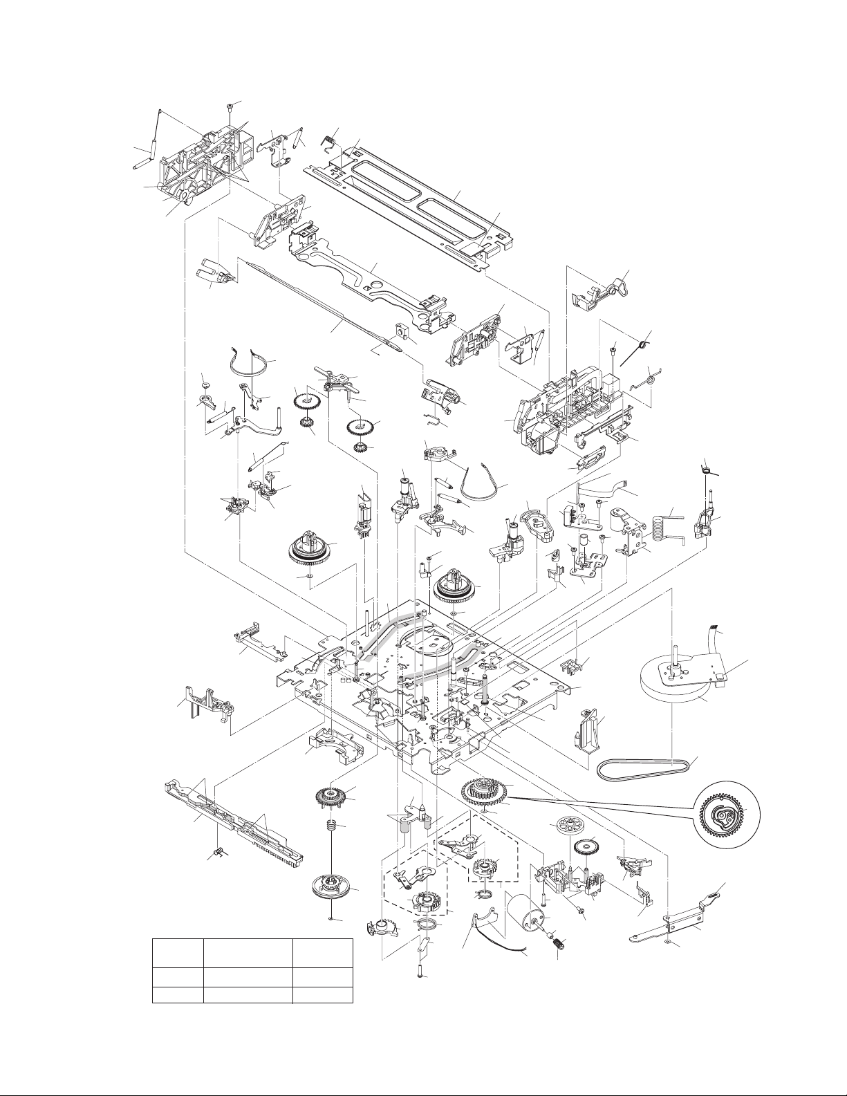
3.3 VHS MECHANISM ASSEMBLY
112
AA
124
127
128
138
126
AA
110
AA
134
Classification
Grease
Oil
118
77
72
76
71
AA
73
AA
69
70
KYODO-SH-JB
COSMO-HV56
AA
37
AA
78
Part No.
137
122
130
121
74
BB
90
75
89
38
AA
36
107
AA
102
AA
88
BB
89
4
105
BB
BB
AA
95
AA
96
93
94
Symbol in
drawing
AA
131
90
21
AA
18B
18A
22
79
BB
15
AA
19
20
LOADING MOTOR
BOARD ASSY [5][5]
16
120
82
31
30
BB
138
151
123
125
126
119
111
115
WR3
AA
56
52
58
3
AA
67
55
53
161
91
1
39
68
AA
62
61
59
60
63
66
AA
80
105
23B
117
26
86
AA
40
AA
AA
64
65
23A
23
83
81
107
24
18
113
112
116
114
A/C HEAD
BOARD ASSY [1][2]
WR2
57
58
42
84
48
NOTE: The section marked in AA and BB
indicate lubrication and greasing areas.
50
44
47
49
WR1
51
85
87
AA
AA
46
Fig.3-3-1
(No.86700)3-7
Page 52

3.3.1 VHS MECHANISM ASSEMBLY PARTS LIST
• Since parts numbers described here are the numbers at the time of manualissue, they are subject to change without notice. Therefore, be sure to see a parts list in the service manual of each model as for parts numbers.
System VHS S-VHS
**Job No. V15D Series V16D Series V15S Series V16S Series
Part Name
MAIN DECK ASSY 1 LP21039-001N LP21039-001S LP21039-0 01R LP21039-001S
GUIDE POLE CAP 3 LP40097-002D ←←←
FULL ERASE HEAD 4 QAH0082-001 ←←←
LOAD.GEAR BASE 15 LP30958-001B ←←←
SCREW,X2 16 QYTPST2620Z ←←←
LORD.GEAR(SUPPLY) ASSY 18 LP40798-001A ←←←
LORD.GEAR(SUPPLY) 18A LP21040-001A ←←←
LORD.ARM(SUPPLY) ASSY 18B LP40799-001A ←←←
TORSION SPRING(SUPPLY) 19 LP40837-001A ←←←
FIXING PLATE 20 LP40903-001A ←←←
POLE BASE ASSY(SUPPLY) 21 LP40806-001D ←←←
LOAD GEAR 22 LP30959-002A ←←←
LORD. GEAR(TAKE UP) ASSY 23 LP40802-001B LP40802-001C LP40802-001B LP40802-001C
LORD. GEAR(TAKE UP) 23A LP21041-001B LP21041-0 01C LP21041-001B LP21041-001C
LORD.ARM(TAKE UP) ASSY 23B LP40803-001A ←←←
TORSION SPRING(TAKE UP) 24 LP40838-001A ←←←
POLE BASE ASSY(TAKE UP) 26 LP40808-001F LP40808-001E ←←
ARM BASE 30 - ← LP31020-004A ←
SCREW 31 - ← QYTDST2606Z TU LEVER 36 LP21055-001E ←←←
TENSION SPRING 37 LP40943-001A ←←←
T-UP HEAD 38 LP40859-001D ←←←
LID GUIDE 39 LP30961-001C ←←←
SPACER 40 LP30002-0B7A ←← PINCH ROLLER ARM ASSY 42 LP40810-001A ←←←
TORSION SPRING 44 LP40840-001C LP40840-001D ←←
PRESS LEVER 46 LP30963-001B ←←←
SLIT WASHER 47 PQM30017-24 ←←←
S-SWITCH 48 - ← LP40930-002E ←
GIDE ARM ASSY 49 LP40813-001D ←←←
TORSION SPRING 50 LP40841-001A ←←←
SPACER 51 LP30002-090A ←← A/C HEAD 52 QAH0081-001 ←←←
HEAD BASE 53 LP30965-001A ←←←
COMPRESSION SPRING 55 LP40842-001A LP40842-001D LP40842-001A LP40842-001D
SCREWX1 A/C HEAD *56 QYTDST2006M ←←←
A/C HEAD SCREW,X2 *57 LP41036-001A ←←←
SCREW,X2 A/C HEAD *58 QYTDST2606Z ←←←
LOADING MOTOR 59 QAR0023-001 ←←←
SCREW,X2 60 QYTPSP3003Z ←←←
MOTOR BRACKET 61 LP21056-002F LP21056-002G ←←
TAP SCREW 62 QYTPST2620Z ←←←
WORM BEARING 63 LP40814-001B ←←←
CONTROL CAM 64 LP21044-001D ←←←
SLIT WASHER 65 PQM30017-24 ←←←
WORM GEAR 66 LP40815-001A ←←←
HELICAL GEAR 67 LP40816-001B ←←←
CONNECT GEAR 68 LP40817-001A ←←←
Symbol
No.
Part No. Part No. Part No. Part No.
3-8 (No.86700)
Page 53

System VHS S-VHS
**Job No. V15D Series V16D Series V15S Series V16S Series
Part Name
CONTROL PLATE 69 LP10400-001H ←←LP10400-001J
TORTION SPRING 70 LP40843-001A ←←←
TENSION ARM ASSY 71 LP40818-001B ←←←
TENSION SPRING 72 LP40844-001C LP40844-001E LP40844-001D LP40844-001E
TENSION ARM BASE 73 LP21045-001D ←←←
TENSION BAND ASSY 74 LP40821-001A ←←←
BAND HOLDER-1 75 LP30967-001B ←←←
BAND HOLDER-2 76 LP30968-001C ←←←
ADJUST PIN 77 LP40822-002B ←←←
TENSION ARM LEVER 78 LP31000-005E ←←←
MAIN BRAKE(TAKE UP) 79 LP21046-001C ←←←
BAND BRAKE ASSY 80 LP40824-001A ←←←
BRAKE LEVER 81 LP30969-002A LP30969-002B LP30969-002A LP30969-002B
TENSION SPRING 82 LP30003-033B ←←←
TENSION SPRING 83 LP30003-035B ←←←
CAPSTAN BRAKE ASSY 84 LP40825-001B ←←←
CAPSTAN MOTOR 85 QAR0204-002 ←←←
SCREW,X3 CAPSTAN MOTOR 86 QYTPSG2606M QYTPSG2606Z QYTPSG2606M QYTPSG2606Z
BELTCAPSTAN MOTOR 87 LP30005-010A ←←←
IDLER ARM 88 LP30970-001A ←←←
IDLER GEAR 1,X2 89 LP40828-004A ←←←
IDLER GEAR 2,X2 90 LP40829-001B LP40829-002A LP40829-001B LP40829-002A
WIRE HOLDER 91 LP31014-001A ←←←
CLUTCH UNIT 93 LP40934-001B ←←←
SLIT WASHER 94 PQM30017-47 ←←←
DIRECT GEAR 95 LP30973-001A ←←←
COMPRESS. SPRING 96 LP40939-001A ←←←
CHANGE LEVER 102 LP30974-001B ←←←
REEL DISK,X2 105 LP21049-001A ←←←
SPACER,X2 107 LP30017-004A ←←←
SIDE FRAME(L) 110 LP10401-001F LP10401-001H LP10401-001F LP10401-001H
SIDE FRAME(R) 111 LP10402-001F LP10402-001K LP10402-001G LP10402-001K
SCREW,X2 112 QYTDST2606Z ←←←
TORSION SPRING 113 LP40917-001C LP40917-001D ←←
SIDE PLATE 114 LP30976-001D LP30976-001E ←←
LIMIT PLATE 115 LP30977-002D ←←←
LIMIT SPRING 116 LP40846-001C ←←←
DRIVE LEVER 117 LP31100-001B ←←←
DRIVE ARM(L) 118 LP30978-001B ←←←
DRIVE ARM(R) 119 LP30979-001H LP30979-001N LP30979-001H LP30979-001N
TORSION SPRING 120 LP40847-001B ←←←
CONNECT PLATE 121 LP30980-001A LP30980-001E LP30980-001B LP30980-001E
SIDE HOLDER(L) 122 LP10403-001C ←←←
SIDE HOLDER(R) 123 LP10404-001D LP10404-001E ←←
LOCK LEVER(L) 124 LP30983-001A LP30983-001B LP30983-001A LP30983-001B
LOCK LEVER(R) 125 LP30984-001A LP30984-001B LP30984-001A LP30984-001B
TENSION SPRING,X2 126 LP40924-001C LP40924-001D ←←
EARTH SPRING(1) 127 LP40856-001A ← LP40856-001B LP40972-001A
EARTH SPRING(2) 128 LP40857-001B ←←←
C.HOLDER ASSY 130 LP30981-001E LP30981-001G LP30981-001F LP30981-001G
C.H STOPPER 131 LP31135-001A - LP31135-001A -
Symbol
No.
Part No. Part No. Part No. Part No.
(No.86700)3-9
Page 54

System VHS S-VHS
**Job No. V15D Series V16D Series V15S Series V16S Series
Part Name
R.SAFETY LEVER 134 LP21051-002C ←←←
TOP FRAME 137 LP21052-001F LP21052-001J LP21052-001H LP21052-001J
SPACER 138 LP30002-0A7A - LP30002-0A7A DOOR OPENER 151 LP30985-001G ←←←
TAPE GUIDE 161 - LP40993-001A - LP40993-001A
E-CARD WIRE DRUM.M WR1 WJT0059-001C WJT0059-001E WJT0059-001D WJT0059-001E
E-CARD WIRE AC HEAD CN2001 WR2 WJT0067-001B ←←←
E-FL/RB WIRE LOADING MOTOR WR3 WJS0022-001A ←←←
MEMO
NOTE:
MARK ← is same as left.
MARK - is not used.
MARK * shows that Symbol No. and Parts No. may sometimes be different from those in each manual. See the table below for final Symbol No. and Parts No.
MARK ** is Job No.
To identify a model, see the Job No. of the model.
Job No. is shown just above the service manual number at the lower right of the service manual of each model.
Symbol
No.
- PMD0035B-C PMD0040A-C
Part No. Part No. Part No. Part No.
PMD0036B-C
/PMD0039A-C
PMD0037A-C
/PMD0041A-C
3-10 (No.86700)
Page 55

DIGITAL VIDEO CAMERA
Dear Customer,
Thank you for purchasing this digital
video camera. Before use, please
read the safety information and
precautions contained in the pages
3 – 4 and 10 to ensure safe use of
this product.
ENGLISH
GR-D290
GR-D270
Please visit our Homepage on the World Wide Web for
Digital Video Camera:
http://www.jvc.co.jp/english/cyber/
For Accessories:
http://www.jvc.co.jp/english/accessory/
GETTING STARTED
VIDEO RECORDING &
PLAYBACK
DIGITAL STILL CAMERA
(D.S.C.) RECORDING &
PLAYBACK 25
ADVANCED FEATURES
REFERENCES
TERMS
For Customer Use:
Enter below the Model No. and
Serial No. which is located on the
bottom of the camcorder. Retain this
information for future reference.
Model No.
Serial No.
18
31
47
Back cover
6
INSTRUCTIONS
To deactivate the demonstration,
set “DEMO MODE” to “OFF”.
(墌 pg. 31, 33)
LYT1354-001A
EN
Page 56
2 EN
Major Features of this Camcorder
Wipe/Fader Effects
You can use the Wipe/Fader Effects to make
pro-style scene transitions. (墌 pg. 41)
Fade in
Fade out
Program AE with Special Effects
For example, “SPORTS” mode allows fastmoving images to be captured one frame at a
time, for vivid, stable slow-motion. (墌 pg. 42)
LED Light
You can brighten the subject in the dark place
with the LED Light. (墌 pg. 37)
Backlight Compensation
Simply pressing the BACK LIGHT button
brightens the image darkened by backlight.
(墌 pg. 40)
● You can also select a spot metering area so
that more precise exposure compensation
is available. (墌 pg. 40, Spot Exposure
Control)
Data Battery
You can check the battery status by simply
pressing the DATA button. (墌 pg. 14)
BATTERY CONDITION
100%
50%
0%
MAX TIME
LCD
FINDER
min
min
Live Slow
You can record and play back precious or
hard-to-see moments at a slow speed. The
sound is recorded and played back in real
time. (墌 pg. 37)
Page 57
SAFETY PRECAUTIONS
CAUTION
RISK OF ELECTRIC SHOCK
DO NOT OPEN
CAUTION: TO REDUCE THE RISK OF ELECTRIC SHOCK,
DO NOT REMOVE COVER (OR BACK).
NO USER-SERVICEABLE PARTS INSIDE.
REFER SERVICING TO QUALIFIED SERVICE PERSONNEL.
The lightning flash with arrowhead symbol, within an
equilateral triangle, is intended to alert the user to the
presence of uninsulated "dangerous voltage" within the
product's enclosure that may be of sufficient magnitude
to constitute a risk of electric shock to persons.
The exclamation point within an equilateral triangle is
intended to alert the user to the presence of important
operating and maintenance (servicing) instructions in
the literature accompanying the appliance.
WARNING: TO PREVENT FIRE OR SHOCK
HAZARD, DO NOT EXPOSE THIS UNIT TO
RAIN OR MOISTURE.
CAUTIONS:
● This camcorder is designed to be used with
NTSC-type color television signals. It cannot be
used for playback with a television of a different
standard. However, live recording and LCD
monitor/viewfinder playback are possible
anywhere.
● This product includes patented and other
proprietary technology and will operate only
with JVC Data Battery. Use the JVC
BN-VF707U/VF714U/VF733U battery packs
and, to recharge them or to supply power to the
camcorder from an AC outlet, use the provided
multi-voltage AC Adapter. (An appropriate
conversion adapter may be necessary to
accommodate different designs of AC outlets in
different countries.)
Caution on Replaceable lithium battery
The battery used in this device may present a fire
or chemical burn hazard if mistreated.
Do not recharge, disassemble, heat above 100°C
(212°F) or incinerate.
Replace battery with Panasonic (Matsushita
Electric), Sanyo, Sony or Maxell CR2025.
Danger of explosion or Risk of fire if the battery is
incorrectly replaced.
● Dispose of used battery promptly.
● Keep away from children.
● Do not disassemble and do not dispose of in
fire.
EN 3
NOTES:
● The rating plate (serial number plate) and
safety caution are on the bottom and/or the
back of the main unit.
● The rating information and safety caution of the
AC Adapter are on its upper and lower sides.
This product has a fluorescent lamp that contains
a small amount of mercury. Disposal of these
materials may be regulated in your community
due to environmental considerations.
For disposal or recycling information please
contact your local authorities, or the Electronics
Industries Alliance:
<http://www.eiae.org>
Page 58

4 EN
When the equipment is installed in a cabinet or on
a shelf, make sure that it has sufficient space on
all sides to allow for ventilation (10 cm (3-15/16")
or more on both sides, on top and at the rear).
Do not block the ventilation holes.
(If the ventilation holes are blocked by a
newspaper, or cloth etc. the heat may not be able
to get out.)
No naked flame sources, such as lighted candles,
should be placed on the apparatus.
When discarding batteries, environmental
problems must be considered and the local rules
or laws governing the disposal of these batteries
must be followed strictly.
The apparatus shall not be exposed to dripping or
splashing.
Do not use this equipment in a bathroom or
places with water.
Also do not place any containers filled with water
or liquids (such as cosmetics or medicines, flower
vases, potted plants, cups etc.) on top of this unit.
(If water or liquid is allowed to enter this
equipment, fire or electric shock may be caused.)
Do not point the lens or the viewfinder directly into
the sun. This can cause eye injuries, as well as
lead to the malfunctioning of internal circuitry.
There is also a risk of fire or electric shock.
CAUTION!
The following notes concern possible physical
damage to the camcorder and to the user.
When carrying, be sure to always securely attach
and use the provided strap. Carrying or holding
the camcorder by the viewfinder and/or the LCD
monitor can result in dropping the unit, or in a
malfunction.
Take care not to get your finger caught in the
cassette holder cover. Do not let children operate
the camcorder, as they are particularly
susceptible to this type of injury.
Do not use a tripod on unsteady or unlevel
surfaces. It could tip over, causing serious
damage to the camcorder.
CAUTION!
Connecting cables (Audio/Video, S-Video, etc.) to
the camcorder and leaving it on top of the TV is
not recommended, as tripping on the cables will
cause the camcorder to fall, resulting in damage.
IMPORTANT SAFETY INSTRUCTIONS
1. Read these instructions.
2. Keep these instructions.
3. Heed all warnings.
4. Follow all instructions.
5. Do not use this apparatus near water.
6. Clean only with dry cloth.
7. Do not block any ventilation openings. Install in
accordance with the manufacturer’s instructions.
8. Do not install near any heat sources such as
radiators, heat registers, stoves, or other
apparatus (including amplifiers) that produce
heat.
9. Only use attachments/accessories specified by
the manufacturer.
10. Use only with the
cart, stand, tripod,
bracket, or table
specified by the
manufacturer, or
sold with the
apparatus. When a
cart is used, use
caution when
moving the cart/
apparatus combination to avoid injury from tipover.
11. Unplug this apparatus during lightning storms or
when unused for long periods of time.
12. Refer all servicing to qualified service
personnel. Servicing is required when the
apparatus has been damaged in any way, such
as power-supply cord or plug is damaged, liquid
has been spilled or objects have fallen into the
apparatus, the apparatus has been exposed to
rain or moisture, does not operate normally, or
has been dropped.
Page 59

GETTING STARTED 6
Index................................................................. 6
Provided Accessories ..................................... 11
Power.............................................................. 13
Operation Mode.............................................. 14
Language Settings..........................................15
Date/Time Settings ......................................... 15
Grip Adjustment.............................................. 15
Viewfinder Adjustment.................................... 16
Brightness Adjustment Of The Display........... 16
Tripod Mounting.............................................. 16
Loading/Unloading A Cassette....................... 16
Loading/Unloading A Memory Card................ 17
VIDEO RECORDING & PLAYBACK 18
VIDEO RECORDING ...........................................18
Basic Recording.............................................. 18
Tape Remaining Time ................................ 18
LCD Monitor And Viewfinder ...................... 18
Zooming...................................................... 19
Journalistic Shooting .................................. 19
Time Code .................................................. 19
Quick Review.............................................. 20
Recording From The Middle Of A Tape...... 20
VIDEO PLAYBACK ............................................. 20
Normal Playback............................................. 20
Still Playback ..............................................20
Shuttle Search............................................ 21
Blank Search .............................................. 21
Connections To A TV Or VCR........................ 22
Playback Using The Remote Control (GR-D290
only)............................................................ 23
DIGITAL STILL CAMERA (D.S.C.) RECORDING
& PLAYBACK 25
D.S.C. RECORDING............................................25
Basic Shooting (D.S.C. Snapshot).................. 25
Interval Shooting......................................... 25
D.S.C. PLAYBACK .............................................. 26
Normal Playback Of Images........................... 26
Auto Playback Of Images ............................... 27
Index Playback Of Files.................................. 27
Removing On-Screen Display ........................ 27
ADDITIONAL FEATURES FOR D.S.C. .................... 28
Dubbing Still Images Recorded On A Tape To A
Memory Card.............................................. 28
Resetting The File Name................................ 28
Protecting Files............................................... 28
Deleting Files.................................................. 29
Setting Print Information (DPOF Setting)........ 29
Initializing A Memory Card.............................. 30
CONTENTS
EN
ADVANCED FEATURES 31
MENUS FOR DETAILED ADJUSTMENT.................. 31
Changing The Menu Settings......................... 31
Recording Menus............................................ 32
Playback Menus ............................................. 35
FEATURES FOR RECORDING............................... 37
LED Light........................................................37
Live Slow ........................................................ 37
5-Second Recording....................................... 37
Night-Alive ...................................................... 38
Snapshot (For Video Recording).................... 38
Manual Focus ................................................. 38
Exposure Control............................................ 39
Iris Lock .......................................................... 39
Backlight Compensation................................. 40
Spot Exposure Control.................................... 40
White Balance Adjustment.............................. 40
Manual White Balance Adjustment................. 41
Wipe Or Fader Effects .................................... 41
Program AE With Special Effects ................... 42
EDITING............................................................ 43
Dubbing To A VCR ......................................... 43
Dubbing To Or From A Video Unit Equipped With
A DV Connector (Digital Dubbing).............. 44
Connection To A Personal Computer............. 45
Audio Dubbing (GR-D290 only)...................... 46
Insert Editing (GR-D290 only)......................... 46
REFERENCES 47
TROUBLESHOOTING.......................................... 47
USER MAINTENANCE.........................................51
CAUTIONS ........................................................ 52
SPECIFICATIONS................................................ 55
TERMS Back cover
5
Page 60

6 EN
Index
GETTING STARTED
UV
1WB C
G
c
d
e
g
D E
X
8 P
Q
F
R
S
9J
hfi
j
O
Y
KM NT
L
aZb
Page 61

Controls
A Stop Button [8] (墌 pg. 20)
Index Button [INDEX] (墌 pg. 27)
Backlight Compensation Button [BACK
LIGHT] (墌 pg. 40)
B Play/Pause Button [4/9] (墌 pg. 20)
Manual Focus Button [FOCUS] (墌 pg. 38)
C Rewind Button [
Menu select Button [–] (墌 pg. 15)
Quick Review Button [ ] (墌 pg. 20)
D Fast-Forward Button [
Menu select Button [+] (墌 pg. 15)
Night Button [NIGHT] (墌 pg. 38)
E Menu Button [MENU] (墌 pg. 31)
Data Battery Button [DATA] (墌 pg. 14)
F VIDEO/MEMORY Switch (墌 pg. 14)
G LED Light Button [LIGHT] (墌 pg. 37)
H Diopter Adjustment Control (墌 pg. 16)
I Snapshot Button [SNAPSHOT]
(墌 pg. 25, 38)
Live Slow Button [SLOW] (墌 pg. 31, 37)
J Power Zoom Lever [T/W] (墌 pg. 19)
Speaker Volume Control [VOL. +, –]
(墌 pg. 20)
K Battery Release Button [PUSH BATT.]
(墌 pg. 13)
L Recording Start/Stop Button (墌 pg. 18)
M Power Switch [A, M, PLAY, OFF] (墌 pg. 14)
N Lock Button (墌 pg. 14)
O Cassette Open/Eject Switch [OPEN/EJECT]
(墌 pg. 16)
3
] (墌 pg. 20)
5
] (墌 pg. 20)
Connectors
The connectors are located beneath the covers.
P USB (Universal Serial Bus) Connector
(墌 pg. 45)
Q Audio/Video Output Connector [AV]
(墌 pg. 22, 43)
R DC Input Connector [DC] (墌 pg. 13)
S Digital Video Connector [DV IN/OUT] (i.Link*)
(墌 pg. 44, 45)
* i.Link refers to the IEEE1394-1995 industry
specification and extensions thereof. The logo
is used for products compliant with the i.Link
standard.
Indicators
T POWER/CHARGE Lamp (墌 pg. 13, 18)
GETTING STARTED
EN 7
Other Parts
U Monitor Latch (墌 pg. 18)
V LCD Monitor (墌 pg. 18, 19)
W Viewfinder (墌 pg. 16)
X Card Cover [MEMORY CARD] (墌 pg. 17)
Y Battery Pack Mount (墌 pg. 13)
Z Shoulder Strap Eyelet (墌 pg. 11)
a Speaker (墌 pg. 20)
b Grip Strap (墌 pg. 15)
c Lens
d LED Light (墌 pg. 37)
(When using an optional conversion lens, it
may cover this area and block the light.)
e Remote Sensor (GR-D290 only) (墌 pg. 23)
f Camera Sensor
(Be careful not to cover this area, a sensor
necessary for shooting is built-in here.)
g Stereo Microphone (墌 pg. 46)
h Stud Hole (墌 pg. 16)
i Tripod Mounting Socket (墌 pg. 16)
j Cassette Holder Cover (墌 pg. 16)
Page 62

8 EN
GETTING STARTED
LCD Monitor/Viewfinder Indications
During Video Recording Only
2
4
356
1
1h40m
REC
7
8
9
0
e
w
SOUND12BIT
15:55
q
a Selected Wipe/Fader Effect Indicator
(墌 pg. 41)
B Tape Running Indicator (墌 pg. 18)
(Rotates while tape is running.)
C Selected Wide Mode Indicator (墌 pg. 33)
D : Live Slow Indicator (墌 pg. 37)
: Snapshot Indicator (墌 pg. 38)
E Recording Speed Mode (SP/LP) (墌 pg. 32)
F Tape Remaining Time (墌 pg. 18)
G REC: (Appears during recording.) (墌 pg. 18)
PAUSE: (Appears during Record-Standby
mode.) (墌 pg. 18)
H Insert Editing/Insert Editing Pause Mode
(墌 pg. 46)
I 5S/Anim.: Displays the 5-Second Recording
mode or Animation recording mode.
(墌 pg. 33)
J Wind Cut Indicator (墌 pg. 33)
K Time Code (墌 pg. 34, 36)
L Digital Image Stabilizer (“DIS”) (墌 pg. 32)
M SOUND 12BIT/16BIT: Sound Mode Indicator
(墌 pg. 32) (Appears for approx. 5 seconds
after turning on the camcorder.)
During D.S.C. Recording Only
634 5
1024
INTERVAL
51
7
a Image Size: 1024 (1024 x 768) or 640
(640x480) (墌 pg. 34)
B Interval Shooting Icon (墌 pg. 25)
C Shooting Icon (墌 pg. 25)
(Appears and blinks during shooting.)
D Card Icon (墌 pg. 25)
: Appears during shooting.
: Blinks in white when a memory card is
not loaded.
: Blinks in yellow while the camcorder is
reading the data in the memory card.
E Picture Quality: (FINE) and
(STANDARD) (in order of quality) (墌 pg. 34)
F Remaining Number Of Shots (墌 pg. 25)
(Displays the approximate remaining number
of shots that can be stored during D.S.C.
recording.)
G Clock Icon (墌 pg. 25)
During Both Video And D.S.C. Recording
8
9
1
25
2
3
4
5
6
7
a Operation Mode (墌 pg. 14)
B : Night-Alive Indicator (墌 pg. 38)
: Gain Up Mode (墌 pg. 32)
C LED Light Indicator (墌 pg. 37)
D White Balance Indicator (墌 pg. 41)
E : Spot Exposure Control Indicator
(墌 pg. 40)
: Backlight Compensation Indicator
(墌 pg. 40)
±: Exposure Adjustment Indicator (墌 pg. 39)
F Selected Program AE With Special Effects
Indicator (墌 pg. 42)
G Iris Lock Indicator (墌 pg. 39)
x
BRIGHT
W
T
N
OV
10
:10000A
O
50m
er
'
5
M
0
q
w
Page 63

H Approximate Zoom Ratio (墌 pg. 19)
I Zoom Indicator (墌 pg. 19)
J O: (Appears when taking Snapshot.)
(墌 pg. 25, 38)
SLOW
: (Appears when using Live Slow.)
(墌 pg. 37)
K Brightness Control Indicator (LCD monitor/
Viewfinder) (墌 pg. 16)
L Battery Remaining Power Indicator
(墌 pg. 49)
M Date/Time (墌 pg. 15)
N Manual Focus Adjustment Indicator
(墌 pg. 38)
During Video Playback
1
BIT
1L2
2 0 :/2M
I
X
BLANK SEARCH
PUSH "STOP" BUTTON
N
TO CANCEL
O
L
M
E
U
V
1
:
2
5
0
9
a Sound Mode Indicator (墌 pg. 35)
B Blank Search Indicator (墌 pg. 21)
C : Live Slow Indicator (墌 pg. 37)
: Snapshot Indicator (墌 pg. 35, 38)
D Tape Speed (墌 pg. 32)
E 4: Playback
5
: Fast-Forward/Shuttle Search
3
: Rewind/Shuttle Search
9: Pause
9 U: Forward Frame-By-Frame Playback/
Slow-Motion
Y 9: Reverse Frame-By-Frame Playback/
Slow-Motion
D: Audio Dubbing
9D: Audio Dubbing Pause
(Appear while a tape is running.)
F Sound Input For Audio Dubbing (墌 pg. 46)
(GR-D290 only)
G Battery Remaining Power Indicator
(墌 pg. 49)
H Date/Time (墌 pg. 34, 36)
43
2
O1V01
:
00
5
MIC
50m
0 '0
6
5
M
A
8
GETTING STARTED
I VOLUME: Volume Level Indicator (墌 pg. 20)
BRIGHT: Brightness Control Indicator (LCD
monitor/Viewfinder) (墌 pg. 16)
J Time Code (墌 pg. 34, 36)
During D.S.C. Playback
1
BR IGHT
4
a Operation Mode Indicator (墌 pg. 27)
B Folder/File Number (墌 pg. 27)
C Battery Remaining Power Indicator
(墌 pg. 49)
D Brightness Control Indicator (LCD monitor/
Viewfinder) (墌 pg. 16)
7
EN 9
2
100-0013
50m
3
Page 64

10 EN
GETTING STARTED
Before Using This Camcorder
Make sure you only use cassettes with the Mini
DV mark .
Make sure you only use memory cards with the
mark or .
This camcorder is designed exclusively for the
digital video cassette, SD Memory Card and
MultiMediaCard. Only cassettes marked “ ” and
memory cards marked “ ” or
“ ” can be used with this unit.
Remember that this camcorder is not
compatible with other digital video formats.
Remember that this camcorder is intended for
private consumer use only.
Any commercial use without proper permission is
prohibited. (Even if you record an event such as a
show, performance or exhibition for personal
enjoyment, it is strongly recommended that you
obtain permission beforehand.)
Before recording important video, be sure to
make a trial recording.
Play back your trial recording to make sure the
video and audio have been recorded properly.
We recommend cleaning your video heads
before use.
If you haven’t used your camcorder for a while, the
heads may be dirty. We recommend periodically
cleaning the video heads with a cleaning cassette
(optional).
Be sure to store your cassette tapes and
camcorder in the proper environment.
Video heads can become dirty more easily if your
cassette tapes and camcorder are stored in a dusty
area. Cassette tapes should be removed from the
camcorder and stored in cassette cases. Store the
camcorder in a bag or other container.
Use SP (Standard) mode for important video
recordings.
LP (Long Play) mode lets you record 50% more
video than SP (Standard) mode, but you may
experience mosaic-like noise during playback
depending on the tape characteristics and the
usage environment.
So, for important recordings, we recommend using
SP mode.
It is recommended that you use JVC brand
cassette tapes.
Your camcorder is compatible with all brands of
commercially available cassette tapes complying
with the MiniDV standard, but JVC brand cassette
tapes are designed and optimized to maximize the
performance of your camcorder.
Also read “CAUTIONS” on pages 52 – 54.
®
● Microsoft
trademarks or trademarks of Microsoft
Corporation in the United States and/or other
countries.
● Macintosh is a registered trademark of Apple
Computer, Inc.
● QuickTime is a registered trademark of Apple
Computer, Inc.
and Windows® are either registered
Page 65
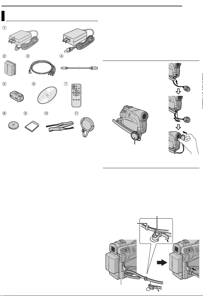
Provided Accessories
OR
GETTING STARTED
NOTES:
● In order to maintain optimum performance of the
camcorder, provided cables may be equipped with
one or more core filter. If a cable has only one core
filter, the end that is closest to the filter should be
connected to the camcorder.
● Make sure to use the provided cables for
connections. Do not use any other cables.
EN 11
How To Attach The Lens Cap
To protect the lens, attach
the provided lens cap to the
camcorder as shown in the
illustration.
NOTE:
To confirm the lens cap is on
correctly make sure the cap is
flush to the camcorder.
a AC Adapter AP-V16U or AP-V14U
b Battery Pack BN-VF707U
c Audio/Video Cable (ø3.5 mini-plug to RCA
plug)
d USB Cable
e Core Filter (for USB cable, 墌 pg. 12 for
attachment)
f CD-ROM
g Remote Control Unit RM-V720U (GR-D290
only)
h Lithium Battery CR2025* (for remote control
unit) (GR-D290 only)
i Memory Card 8 MB (Already inserted in the
camcorder) (GR-D290 only)
j Shoulder Strap (see the right column for
attachment)
k Lens Cap (see the right column for
attachment)
* A lithium battery is pre-installed in the Remote
Control Unit at time of shipment (with insulation
sheet). To use the Remote Control Unit, remove
the insulation sheet.
Place here during
shooting.
How To Attach The Shoulder Strap
Follow the illustration.
1 Thread the strap through the eyelet.
2 Fold it back and thread it through the strap
guide and the buckle.
● To adjust the length of the strap, loosen and then
tighten the strap in the buckle.
3 Slide the strap guide fully towards the eyelet.
Buckle
Strap guide
1
Eyelet
2
2
3
Page 66

12 EN
GETTING STARTED
How To Attach The Core Filter
Attach the core filters to the cables. The core
filter reduces interference.
1 Release the stoppers on both ends of the
core filter.
Stopper
2 Run the cable through the core filter, leaving
approx. 3 cm (1-3/16") of cable between the
cable plug and the core filter.
Wind the cable once around the outside of the
core filter as shown in the illustration.
3 cm (1-3/16")
Core filter
Wind once.
3 Close the core filter until it clicks shut.
NOTES:
● Take care not to damage the cable.
● When connecting a cable, attach the end with the
core filter to the camcorder.
Page 67

Power
This camcorder’s 2-way power supply system
lets you choose the most appropriate source of
power. Do not use provided power supply units
with other equipment.
Charging The Battery Pack
Power switch
M A
OFF
PLAY
POWER/
CHARGE
Open the cover.
AC Adapter
1 Set the Power Switch to “OFF”.
2 With the arrow on the battery pack pointing
downward, push the battery pack slightly against
the battery pack mount a.
3 Slide down the battery pack until it locks in
place b.
4 Connect the AC Adapter to the camcorder.
5 Plug the AC Adapter into an AC outlet. The
POWER/CHARGE lamp on the camcorder
blinks to indicate charging has started.
6 When the POWER/CHARGE lamp goes out,
charging is finished. Unplug the AC Adapter
from the AC outlet. Disconnect the AC Adapter
from the camcorder.
POWER/CHARGE lamp
Battery pack mount
PUSH BATT.
Battery pack
Arrow
mark
To DC connector
To AC outl et
GETTING STARTED
EN 13
To detach the battery pack
Slide the battery pack upward while pressing
PUSH BATT. to detach it.
Battery pack Charging time
BN-VF707U* Approx. 1 hr. 30 min.
BN-VF714U Approx. 2 hr. 40 min.
BN-VF733U Approx. 5 hr. 40 min.
* Provided
NOTES:
● It is recommended that only genuine JVC
batteries are used in this camcorder. Using
generic non-JVC batteries can cause damage to
the internal charging circuitry.
● If the protective cap is attached to the battery
pack, remove it first.
● During charging, the camcorder cannot be
operated.
● Charging is not possible if the wrong type of
battery is used.
● When charging the battery pack for the first time
or after a long storage period, the POWER/
CHARGE lamp may not light. In this case, remove
the battery pack from the camcorder, then try
charging again.
● If the battery operation time remains extremely
short even after having been fully charged, the
battery is worn out and needs to be replaced.
Please purchase a new one.
● Since the AC Adapter processes electricity
internally, it becomes warm during use. Be sure to
use it only in well-ventilated areas.
● Using the optional AA-VF7 Battery Charger, you
can charge the BN-VF707U/VF714U/VF733U
battery pack without the camcorder.
● After 5 minutes has elapsed in Record-Standby
mode with the cassette inserted, the camcorder
will automatically turn off its power supplied from
the AC adapter. In this case, the battery charge
starts if the battery is attached to the camcorder.
Using The Battery Pack
Perform steps 2 – 3 in “Charging The Battery
Pack”.
Maximum continuous recording time
Battery pack
BN-VF707U* 1 hr. 5 min. 1 hr. 25 min.
BN-VF714U 2 hr. 20 min. 3 hr.
BN-VF733U 5hr.25min. 7hr.5min.
* Provided
LCD monitor
on
Viewfinder on
Page 68
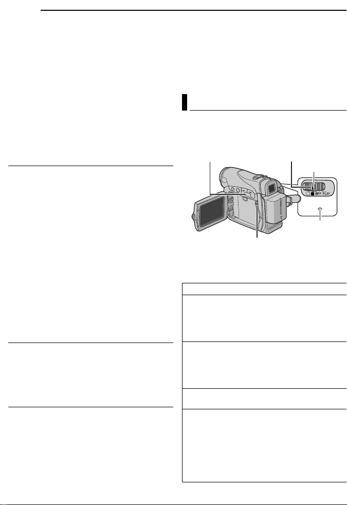
14 EN
A
GETTING STARTED
NOTES:
● Recording time is reduced significantly under the
following conditions:
• Zoom or Record-Standby mode is engaged
repeatedly.
• The LCD monitor is used repeatedly.
• The playback mode is engaged repeatedly.
• The LED Light is used.
● Before extended use, it is recommended that you
prepare enough battery packs to cover 3 times the
planned shooting time.
TTENTION:
Before detaching the power source, make sure that
the camcorder’s power is turned off. Failure to do so
can result in a camcorder malfunction.
Data Battery System
You can check the remaining battery power and
the recordable time.
1) Make sure the battery is attached and the
Power Switch is set to “OFF”.
2) Open the LCD monitor fully.
3) Press DATA, and the battery status screen
appears.
● It can be displayed on the viewfinder when the
LCD monitor is closed.
● It is displayed for approx. 3 seconds if the
button is pressed and released quickly, and for
approx. 15 seconds if the button is pressed
and hold for several seconds.
● If “COMMUNICATION ERROR” appears
instead of the battery status even though you
tried to press DATA several times, there may
be a problem with your battery. In such a case,
consult your nearest JVC dealer.
Using AC Power
Perform step 4 in “Charging The Battery Pack”.
NOTE:
The provided AC Adapter features automatic
voltage selection in the AC range from 110 V to
240 V.
About Batteries
DANGER! Do not attempt to take the batteries
apart, or expose them to flame or excessive
heat, as it may cause a fire or explosion.
WARNING! Do not allow the battery or its
terminals to come in contact with metals, as this
can result in a short circuit and possibly start a
fire.
To resume the original function of the
accurate battery power indication
If the battery power indication differs from the
actual operating time, fully charge the battery, and
then run it down. However this function may not
turn back if the battery was used for a long period
of time under extremely high/low temperature
condition or charged too many times.
Operation Mode
To turn on the camcorder, set the Power Switch
to any operation mode except “OFF” while
pressing down the Lock Button located on the
switch.
MENU/DATA
VIDEO/MEMORY
Choose the appropriate operation mode
according to your preference using the Power
Switch and VIDEO/MEMORY Switch.
Power Switch Position
A (Full Auto Recording):
Allows you to record using NO special effects
or manual adjustments. Suitable for standard
recording.
The “A” indicator appears on the display.
M (Manual Recording):
Allows you to set various recording functions
using the Menus. (墌 pg. 31)
If you want more creative capabilities than Full
Auto Recording, try this mode.
OFF:
Allows you to switch off the camcorder.
PLAY:
● Allows you to play back a recording on the
tape.
● Allows you to display a still image stored in
the memory card or to transfer a still image
stored in the memory card to a PC.
● Allows you to set various playback functions
using the Menus. (墌 pg. 31)
Power Switch
Lock Button
M
A
POWER/
CHARGE
POWER/
CHARGE lamp
Page 69
VIDEO/MEMORY Switch Position
VIDEO:
Allows you to record on a tape or play back a
tape. If “REC SELECT” is set to “ / ”
(墌 pg. 35), still images are recorded both on
the tape and the memory card.
MEMORY:
● Allows you to record in a memory card or
access data stored in a memory card.
● When the Power Switch is set to “A” or “M”,
the currently selected image size appears.
Power-Linked Operation
When the Power Switch is set to “A” or “M”, you
can also turn on/off the camcorder by opening/
closing the LCD monitor or pulling out/pushing in
the viewfinder.
INFORMATION:
The following explanations in this manual
supposes the use of LCD monitor in your
operation. If you want to use the viewfinder,
close the LCD monitor and pull out the
viewfinder fully.
Language Settings
The language on the display can be changed.
(墌 pg. 31, 34, 36)
1 Set the Power Switch to “M” while pressing
down the Lock Button located on the switch.
2 Open the LCD monitor fully. (墌 pg. 18)
3 Press MENU. The Menu Screen appears.
4 Press + or – to select
“n”, and press MENU.
The CAMERA DISPLAY
Menu appears.
5 Press + or – to select
“LANGUAGE”, and press
MENU.
6 Press + or – to select
the desired language, and
press MENU.
7 Press + or – to select
“BRETURN”, and press
MENU twice. The Menu
Screen closes.
LANGUAGE
J
NRETUR
LA DASERA CM I YP
BRIGHT
NCREON S E
LC – T/D
AU
–/TI DA E
MET
OT
OF
– CO TI E
DEM
F
LANGUAGE ENGLISH
–
DEC OK CL C 02
AD .
: 0 0
5
LA DASERA CM I YP
–
ENGLISH
FRANÇAIS
ESPAÑOL
V
' 0 5
PM
GETTING STARTED
Date/Time Settings
The date/time is recorded onto the tape at all
times, but its display can be turned on or off
during playback. (墌 pg. 31, 36)
1 Perform steps 1 – 4 in “Language Settings”
on the left column.
2 Press + or – to select “CLOCK ADJ.”, and
press MENU. The parameter for “Month” is
highlighted.
3 Press + or – to input
the month, and press
MENU. Repeat to input
the day, year, hour and
minute.
4 Press + or – to select
“BRETURN”, and press
MENU twice. The Menu Screen closes.
ASERA CM
O
KCL C
AD
J.
Grip Adjustment
1 Adjust the velcro strip.
2 Pass your right hand
through the loop and grasp
the grip.
3 Adjust your thumb and
fingers through the grip to
easily operate the
Recording Start/Stop
Button, Power Switch and
Power Zoom Lever. Be
sure to fasten the velcro strip to your preference.
EN 15
I Y
D
P
LA
05
02
'
ECD
PM
0
:
5
0
Page 70

16 EN
PAUSE
GETTING STARTED
Viewfinder Adjustment
1 Set the Power Switch to “A” or “M” while
pressing down the Lock Button located on the
switch.
2 Make sure the LCD monitor is closed and
locked. Pull out the viewfinder fully and adjust it
manually for best viewability.
3 Turn the Diopter Adjustment Control until the
indications in the viewfinder are clearly focused.
Example:
Diopter Adjustment Control
CAUTION:
When retracting the viewfinder, take care not to
pinch your fingers.
Brightness Adjustment Of The
Display
1 Set the Power Switch
to “M” or “PLAY” while
pressing down the Lock
Button located on the
switch.
–
2 Open the LCD monitor
fully. (墌 pg. 18)
● To adjust the brightness of
the viewfinder, pull out the
viewfinder fully and set
“PRIORITY” to “FINDER”
(墌 pg. 31, 34).
3 Press MENU. The
Menu Screen appears.
MENU
BRIGHT
4 Press + or – to select “n”, and press MENU.
The CAMERA DISPLAY Menu appears.
5 Press + or – to select “BRIGHT”, and press
MENU. The Menu Screen closes and the
brightness control indicator appears.
6 Press + or – until the appropriate brightness
is reached.
+
7 Press MENU to clear the brightness control
indicator from the display.
Tripod Mounting
To attach the camcorder
to a tripod, align the
direction stud and screw
to the mounting socket
and stud hole on the
camcorder. Then tighten
the screw clockwise.
● Some tripods are not
equipped with studs.
Loading/Unloading A Cassette
The camcorder needs to be powered up to load
or eject a cassette.
Cassette holder
PUSH HERE
OPEN/EJECT
Make sure the window side
is facing out.
1 Slide and hold OPEN/EJECT in the direction
of the arrow, then pull the cassette holder cover
open until it locks. The cassette holder opens
automatically.
● Do not touch internal components.
2 Inser t or remove a tape and press “PUSH
HERE” to close the cassette holder.
● Be sure to press only the section labeled “PUSH
HERE” to close the cassette holder; touching
other parts may cause your finger to get caught in
the cassette holder, resulting in injury or product
damage.
● Once the cassette holder is closed, it recedes
automatically. Wait until it recedes completely
before closing the cassette holder cover.
Cassette holder
cover
Erase
protection tab
Page 71

● When the battery pack’s charge is low, you may
A
not be able to close the cassette holder cover. Do
not apply force. Replace the battery pack with a
fully charged one or use AC power before
continuing.
3 Close the cassette holder cover firmly until it
locks into place.
To protect valuable recordings
Slide the erase protection tab on the back of the
tape in the direction of “SAVE”. This prevents the
tape from being recorded over. To record on this
tape, slide the tab back to “REC” before loading
it.
NOTES:
● If you wait a few seconds and the cassette holder
does not open, close the cassette holder cover
and try again. If the cassette holder still does not
open, turn the camcorder off then on again.
● If the tape does not load properly, open the
cassette holder cover fully and remove the
cassette. A few minutes later, insert it again.
● When the camcorder is suddenly moved from a
cold place to a warm environment, wait a short
time before opening the cassette holder cover.
GETTING STARTED
EN 17
Loading/Unloading A Memory
Card
The provided memory card is already inserted in
the camcorder at the time of purchase.
(GR-D290 only)
Card Cover (MEMORY CARD)
Label
Memory card
Write/erase protection tab
1 Make sure the camcorder’s power is off.
2 Open the card cover (MEMORY CARD).
3 To load a memory card, firmly insert it with
its clipped edge first.
To unload a memory card, push it once. After
the memory card comes out of the camcorder,
pull it out.
● Do not touch the terminal on the reverse side of
the label.
4 Close the card cover.
To protect valuable files (available only for
SD Memory Card)
Slide the write/erase protection tab on the side
of the memory card in the direction of “LOCK”.
This prevents the memory card from being
recorded over. To record on this memory card,
slide the tab back to the position opposite to
“LOCK” before loading it.
NOTES:
● Some brands of memory cards are not compatible
with this camcorder. Before purchasing a memory
card, consult its manufacturer or dealer.
● Before using a new memory card, it is necessary
to format the card. (墌 pg. 30)
TTENTION:
Do not insert or remove the memory card while the
camcorder is turned on, as this may cause the
memory card to be corrupted or cause the
camcorder to become unable to recognize whether
or not the card is installed.
Clipped edge
Page 72

18 EN
VIDEO RECORDING
Basic Recording
NOTE:
Before continuing, perform the procedures listed
below:
● Po wer ( 墌 pg. 13)
● Loading A Cassette (墌 pg. 16)
VIDEO/MEMORY
Power Zoom Lever
Power Switch
Lock Button
POWER/CHARGE Lamp
Recording Start/Stop Button
1 Remove the lens cap. (墌 pg. 11)
2 Open the LCD monitor fully.
3 Set the VIDEO/MEMORY Switch to “VIDEO”.
4 Set the Power Switch to “A” or “M” while
pressing down the Lock Button located on the
switch.
● The POWER/CHARGE lamp lights and the
camcorder enters the Record-Standby mode.
“PAUSE” is displayed.
● To record in LP (Long Play) mode, 墌 pg. 32.
5 To start recording, press the Recording Start/
Stop Button. “T REC” appears on the display
while recording is in progress.
6 To stop recording, press the Recording Start/
Stop Button again. The camcorder re-enters the
Record-Standby mode.
Approximate recording time
Tape
30 min. 30 min. 45 min.
60 min. 60 min. 90 min.
80 min. 80 min. 120 min.
NOTES:
● If the Record-Standby mode continues for
5 minutes, the camcorder’s power shuts off
automatically. To turn the camcorder on again,
push back and pull out the viewfinder again or
close and re-open the LCD monitor.
Recording mode
SP LP
● When a blank portion is left between recorded
scenes on the tape, the time code is interrupted
and errors may occur when editing the tape. To
avoid this, refer to “Recording From The Middle Of
A Tape” (墌 pg. 20).
● To turn the beep sounds off, 墌 pg. 31, 33.
Tape Remainin g Time
Approximate tape remaining
time appears on the display.
“–h––m” means the
camcorder is calculating the
remaining time. When the
remaining time reaches 2 minutes, the indication
starts blinking.
● The time required to calculate and display the
remaining tape length, and the accuracy of the
calculation, may vary according to the type of tape
used.
LCD Monitor And Viewfinder
While using the LCD monitor:
Make sure the viewfinder is pushed back in. Pull
on the end of the LCD monitor and open the
LCD monitor fully. It can rotate 270° (90°
downward, 180° upward).
While using the viewfinder:
Make sure the LCD monitor is closed and
locked. Pull out the viewfinder fully.
180˚
90˚
NOTES:
● The image will not appear simultaneously on the
LCD monitor and the viewfinder. When the
viewfinder is pulled out while the LCD monitor is
opened, you can select which one to use. Set
“PRIORITY” to the desired mode in SYSTEM
Menu. (墌 pg. 31, 34)
● Colored bright spots may appear all over the LCD
monitor or the viewfinder. However, this is not a
malfunction. (墌 pg. 48)
Page 73
Zooming
)
Produces the zoom in/out effect, or an
instantaneous change in image magnification.
Zoom In
Slide the Power Zoom Lever towards “T”.
Zoom Out
Slide the Power Zoom Lever towards “W”.
● The further you slide the Power Zoom Lever, the
quicker the zoom action.
Zoom in (T: Telephoto)
1xW
T
10xW
T
20xW
T
40xW
T
Zoom out (W: Wide angle)
10xW
T
NOTES:
● Focusing may become unstable during Zooming.
In this case, set the zoom while in RecordStandby, lock the focus by using the manual focus
(墌 pg. 38), then zoom in or out in Record mode.
● Zooming is possible to a maximum of 800X, or it
can be switched to 25X magnification using the
optical zoom. (墌 pg. 32)
● Zoom magnification of over 25X is done through
Digital image processing, and is therefore called
Digital Zoom.
● During Digital zoom, the quality of image may
suffer.
● Digital zoom cannot be used when the VIDEO/
MEMORY Switch is set to “MEMORY”.
Macro shooting (as close as approx. 5 cm (2") to
●
the subject) is possible when the Power Zoom
Lever is set all the way to “W”. Also see “TELE
MACRO” in MANUAL Menu on page 33.
● When shooting a subject close to the lens, zoom
out first. If zoomed-in in the auto focus mode, the
camcorder may automatically zoom out
depending on the distance between the
camcorder and the subject. This will not occur
when “TELE MACRO” is set to “ON”. (墌 pg. 33)
Digital zoom zone
25X (optical) zoom zone
Approximate zoom ratio
VIDEO RECORDING
EN 19
Journalistic Shooting
In some situations,
different shooting
angles may provide
more dramatic results.
Hold the camcorder in
the desired position
and tilt the LCD
monitor in the most
convenient direction. It
can rotate 270° (90°
downward, 180°
upward).
Time Code
During recording, a time code is recorded on the
tape. This code is to confirm the location of the
recorded scene on the tape during playback.
Display
Minutes
Seconds
Frames*
12:34:24
* Frames are not displayed during recording.
If recording starts from a blank portion, the time
code begins counting from “00:00:00”
(minute:second:frame). If recording starts from
the end of a previously recorded scene, the time
code continues from the last time code number.
If during recording a blank por tion is left partway
through the tape, the time code is interrupted.
When recording is resumed, the time code starts
counting up again from “00:00:00”. This means
the camcorder may record the same time codes
as those existing in a previously recorded scene.
To prevent this, perform Recording From The
Middle Of A Tape (墌 pg. 20) in the following
cases;
● When shooting again after playing back a
recorded tape.
● When power shuts off during shooting.
● When a tape is removed and re-inserted during
shooting.
● When shooting using a partially recorded tape.
● When shooting on a blank portion located partway
through the tape.
● When shooting again after shooting a scene then
opening/closing the cassette holder cover.
(30 frames = 1 second
Page 74

20 EN
VOL.+/
NOTES:
● The time code cannot be reset.
● During fast-forwarding and rewinding, the time
code indication does not move smoothly.
● The time code is displayed only when “TIME
CODE” is set to “ON”. (墌 pg. 34)
Quick Review
Enables to check the end of the last recording.
1) Press during the Recording-Standby
mode.
2) Tape is rewound for about several seconds
and played back automatically, then pauses in
the Recording-Standby mode for the next shot.
● Distor tion may occur at start of playback. This is
normal.
Recording From The Middle Of A Tape
1) Play back a tape or use Blank Search
(墌 pg. 21) to find the spot at which you want to
start recording, then engage the Still Playback
mode. (See the right column.)
2) Set the Power Switch to “A” or “M” while
pressing down the Lock Button located on the
switch, then start recording.
VIDEO PLAYBACK
Normal Playback
5
3
4/9
Speaker
8
MENU
VIDEO/MEMORY
1 Load a cassette. (墌 pg. 16)
2 Set the VIDEO/MEMORY Switch to “VIDEO”.
3 Set the Power Switch to “PLAY” while
pressing down the Lock Button located on the
switch.
4 To start playback, press 4/9.
5 To stop playback, press 8.
● During Stop mode, press 3 to rewind, or 5
to fast-forward the tape.
To control the speaker volume
Slide the Power Zoom Lever (VOL. +/–) towards
“+” to turn up the volume, or towards “–” to turn
down the volume.
NOTES:
● The playback picture can be viewed in the LCD
monitor, viewfinder or on a connected TV.
(墌 pg. 22)
● If Stop mode continues for 5 minutes when power
is supplied from a battery, the camcorder shuts off
automatically. To turn on again, set the Power
Switch to “OFF”, then to “PLAY”.
● When a cable is connected to the S/AV connector,
the sound is not heard from the speaker.
Still Playback
Pauses during video playback.
1) Press 4/9 during playback.
2) To resume normal playback, press 4/9
again.
● If still playback continues for more than about
3 minutes, the camcorder’s Stop mode is
automatically engaged.
–
Lock Button
M
A
Power
Switch
Page 75

Shuttle Search
A
Allows high-speed search in either direction
during video playback.
1) During playback, press 5 for forward
search, or 3 for reverse search.
2) To resume normal playback, press 4/9.
● During playback, press and hold 5 or 3. The
search continues as long as you hold the button.
Once you release the button, normal playback
resumes.
● A slight mosaic effect appears on the display
during Shuttle Search. This is not a malfunction.
TTENTION:
During Shuttle Search, parts
of the picture may not be
clearly visible, particularly on
the left side of the screen.
Blank Search
Helps you find where you should start recording
in the middle of a tape to avoid time code
interruption. (墌 pg. 19)
1 Load a cassette. (墌 pg. 16)
2 Set the VIDEO/MEMORY Switch to “VIDEO”.
3 Set the Power Switch to “PLAY” while
pressing down the Lock Button located on the
switch.
4 Press MENU. The Menu Screen appears.
5 Press MENU to select “t”. The VIDEO
Menu appears.
6 Press + or – to select “BLANK SRCH”, and
press MENU. The Sub Menu appears.
7 Press + or – to select “EXECUTE”, and press
MENU.
● The “BLANK SEARCH” indication appears and
the camcorder automatically starts reverse or
forward search, then stops at the spot which is
about 3 seconds of tape before the beginning of
the detected blank portion.
● To cancel Blank Search, press 8.
VIDEO PLAYBACK
EN 21
NOTES:
● Before starting Blank Search, if the current
position is at a blank portion, the camcorder
searches in the reverse direction. If the current
position is at a recorded portion, the camcorder
searches in the forward direction.
● If the beginning or end of the tape is reached
during Blank Search, the camcorder stops
automatically.
● A blank portion which is shorter than 5 seconds of
tape may not be detected.
● The detected blank portion may be located
between recorded scenes. Before you start
recording, make sure there is no recorded scene
after the blank portion.
Page 76

22 EN
VIDEO PLAYBACK
Connections To A TV Or VCR
To AV
connector
213
VCR
Open the cover.
Audio/Video cable
(provided)
TV
A Yellow to VIDEO IN (Connect when your TV/
VCR has only A/V input connectors.)
B Red to AUDIO R IN*
C White to AUDIO L IN*
* Not required for watching still images only.
1 Make sure all units are turned off.
2 Connect the camcorder to a TV or VCR as
shown in the illustration.
If using a VCR, go to step 3.
If not, go to step 4.
3 Connect the VCR output to the TV input,
referring to your VCR’s instruction manual.
4 Turn on the camcorder, the VCR and the TV.
5 Set the VCR to its AUX input mode, and set
the TV to its VIDEO mode.
6 Start playback on the camcorder. (墌 pg. 20)
To choose whether or not the following
displays appear on the connected TV
● Date/Time
Set “DATE/TIME” to “AUTO”, “ON” or “OFF”.
(墌 pg. 31, 36)
Or, press DISPLAY on the remote control
(provided with
date indication.
● Time Code
Set “TIME CODE” to “ON” or “OFF”.
(墌 pg. 31, 36)
● Indications other than date/time and time code
Set “ON SCREEN” to “OFF”, “LCD” or “LCD/TV”.
(墌 pg. 31, 36)
NOTES:
● It is recommended to use the AC Adapter as
the power supply instead of the battery pack.
(墌 pg. 14)
● To monitor the picture and sound from the
camcorder without inserting a tape or memory
card, set the camcorder’s Power Switch to “A” or
“M”, then set your TV to the appropriate input
mode.
● Make sure you adjust the TV sound volume to its
minimum level to avoid a sudden burst of sound
when the camcorder is turned on.
GR-D290 only) to turn on/off the
Page 77

Playback Using The Remote
Control (GR-D290 only)
The Full-Function Remote Control Unit can
operate this camcorder from a distance as well
as the basic operations (Playback, Stop, Pause,
Fast-Forward and Rewind) of your VCR. It also
makes additional playback functions possible.
(墌 pg. 24)
Installing The Battery
The remote control uses
one lithium battery
(CR2025).
1 Pull out the battery
holder by pushing the lock
tab.
2 Inser t the battery in the
holder, and be sure to
have the “+” mark visible.
3 Slide the holder back in until you hear a click.
Beam Effective Area (indoor use)
When using the remote
control, be sure to point it
at the remote sensor.
The transmitted beam’s
approximate effective
distance for indoor use is
5 m (16 ft).
NOTE:
The transmitted beam may not be effective or may
cause incorrect operation when the remote sensor
is directly exposed to sunlight or powerful lighting.
Buttons And Functions
2
1
Lock tab
Remote sensor
3
1
VIDEO PLAYBACK
The following buttons are available only when
the camcorder’s Power Switch is set to “PLAY”.
EN 23
B PAUSE Button
● Pauses the tape (墌 pg. 24)
Up Button (墌 pg. 24)
C SLOW Rewind Button (墌 pg. 24)
D REW Button
● Rewind/Reverse Shuttle Search on a tape
(墌 pg. 21)
● Displays previous file in a memory card
(墌 pg. 26)
Left Button (墌 pg. 24)
E INSERT Button (墌 pg. 46)
F SHIFT Button (墌 pg. 24)
G DISPLAY Button (墌 pg. 22, 43)
H SLOW Forward Button (墌 pg. 24)
I PLAY Button
● Starts Playback of a tape (墌 pg. 20)
● Starts Auto Playback of images in a memory
card (墌 pg. 27)
J FF Button
● Forward/Forward Shuttle Search on a tape
(墌 pg. 21)
● Displays next file in a memory card (墌 pg. 26)
Right Button (墌 pg. 24)
K A. DUB Button (墌 pg. 46)
L STOP Button
● Stops the tape (墌 pg. 20)
● Stops Auto Playback (墌 pg. 27)
Down Button (墌 pg. 24)
M EFFECT Button (墌 pg. 24)
N EFFECT ON/OFF Button (墌 pg. 24)
The following buttons are available when the
camcorder’s Power Switch is set to “A” or “M”.
o Zoom (T/W) Buttons
Zoom in/out (墌 pg. 19, 24)
(Also available with the Power Switch set to
“PLAY”)
p START/STOP Button
Functions the same as the Recording Start/
Stop Button on the camcorder.
q S.SHOT Button
Functions the same as SNAPSHOT on the
camcorder.
(Also available with the Power Switch set to
“PLAY”)
A Infrared beam transmitting window
● Transmits the beam signal.
Page 78

24 EN
.
VIDEO PLAYBACK
Zoom (T/W)
SLOW (YI)
PLAY
(Left)
SHIFT
PAUSE or
(Up)
SLOW (IU)
(Right)
STOP or
(Down)
Slow-Motion Playback
During normal video playback, press SLOW (YI
or IU) more than approx. 2 seconds.
● After approx. 10 minutes, normal playback
resumes.
● To pause Slow-Motion playback, press PAU SE
(9).
● To stop Slow-Motion playback, press PLAY (U).
NOTES:
● You can also engage Slow-Motion Playback from
Still Playback by pressing SLOW (YI or IU) more
than approx. 2 seconds.
● During Slow-Motion Playback, due to digital image
processing, the picture may take on a mosaic
effect.
● After SLOW (YI or IU) is pressed and held, the
still image may be displayed for a few seconds,
followed by a blue screen for a few seconds. This
is not a malfunction.
● During Slow-Motion Playback, there will be
disturbances in video and the picture may seem
unstable, especially with steady images. This is
not a malfunction.
Frame-By-Frame Playback
During normal or still playback, press SLOW
(IU) repeatedly for forward or SLOW (YI)
repeatedly for reverse. Each time SLOW (YI or
IU) is pressed, the frame is played back.
Playback Zoom
Magnifies the recorded image up to 32X at any
time during video playback and D.S.C. playback.
1) Press PLAY (U) to start video
playback. Or perform normal
playback of images.
2) At the point you want to zoom
in, press the Zoom Button (T).
● To zoom out, press the Zoom
Button (W).
3) You can move the image on
the screen around to find a
particular portion of the picture.
While holding down SHIFT,
press (Left), (Right),
(Up) and (Down).
● To end zoom, press and hold W until magnification
returns to normal. Or, press STOP (8) and then
press PLAY (U) during video playback.
NOTES:
● Zoom can also be used during slow-motion and still
playback.
● Due to digital image processing, the quality of the
image may suffer.
Playback Special Effects
Allows you to add creative effects to the video
playback image.
CLASSIC FILM: Gives recorded scenes a
strobe effect.
MONOTONE: Like classic black and white
films, your footage is shot in B/W. Used together
with the Cinema mode (墌 pg. 33, “WIDE
MODE”), it enhances the “classic film” effect.
SEPIA: Recorded scenes have a brownish
tint like old photos. Combine this with the
Cinema mode (墌 pg. 33, “WIDE MODE”) for a
classic look.
STROBE: Your recording looks like a
series of consecutive snapshots.
1) To star t
playback,
press PLAY
(U).
2) Press
EFFECT. The
PLAYBACK EFFECT Select Menu appears.
3) Press EFFECT repeatedly to move the
highlight bar to the desired effect.
● The selected function is activated and after
2 seconds the menu disappears.
● To deactivate the selected effect, press EFFECT
ON/OFF. To reactivate the selected effect press
EFFECT ON/OFF again.
● To change the selected effect, repeat from step 2
above.
EFFECT ON/OFF
EFFECT
Page 79

Basic Shooting (D.S.C. Snapshot)
You can use your camcorder as a Digital Still
Camera for taking snapshots. Still images are
stored in the memory card.
NOTE:
Before continuing, perform the procedures listed
below:
● Power ( 墌 pg. 13)
● Loading a Memory Card (墌 pg. 17)
VIDEO/
MEMORY
1 Remove the lens cap.
2 Open the LCD monitor fully. (墌 pg. 18)
3 Set the VIDEO/MEMORY Switch to
“MEMORY”.
4 Set the Power Switch to “A” or “M” while
pressing down the Lock Button located on the
switch.
● To change the Image Size and/or Picture Quality,
墌 pg. 31, 34.
5 Press SNAPSHOT. The “O” indication
appears while the snapshot is being taken.
● Still images are recorded in the snapshot mode
with no frame.
● To delete unwanted still images, refer to “Deleting
Files” (墌 pg. 29).
● When you do not want to hear the shutter sound,
set “BEEP” to “OFF”. (墌 pg. 31, 33)
NOTE:
If shooting is not performed for approx. 5 minutes
when the Power Switch is set to “A” or “M” and
power is supplied from the battery pack, the
camcorder shuts off automatically to save power. To
perform shooting again, push back and pull out the
viewfinder again or close and re-open the LCD
monitor.
SNAPSHOT
Power Switch
Lock Button
D.S.C. RECORDING
Approximate Number of Storable Images
● The number increases or decreases depending
on the Picture Quality/Image Size, etc.
Image Size/Picture
Quality
640 x 480/FINE 47 95 205 425
640 x 480/STANDARD 160 295 625 1285
1024 x 768/FINE 21 47 95 200
1024 x 768/STANDARD 65 145 310 640
Image Size/Picture
Quality
640 x 480/FINE 55 105 215
640 x 480/STANDARD 190 320 645
1024 x 768/FINE 25 50 100
1024 x 768/STANDARD 75 160 320
* Optional
** Provided (GR-D290 only)
SD Memory Card
8MB* 16MB*32MB*64MB*
MultiMediaCard
8MB** 16MB* 32MB*
EN 25
Interval Shooting
During Interval Shooting mode, the camcorder
continues to take snapshots automatically with
an interval of your desired setting.
1 Set “INT.SHOT” to “ON”. (墌 pg. 31, 35)
● “INTERVAL” and “ ” appear.
2 Set “INT.TIME” to the desired shooting
interval. (墌 pg. 31, 35)
3 Set the Power Switch to “A” or “M” while
pressing down the Lock Button located on the
switch.
4 Press SNAPSHOT.
● First shot is taken after 2 seconds.
● The “O” indicator appears while the snapshot
is being taken.
● The clock icon “ ” turns while waiting for the next
shot is being taken.
● The next shot is being taken automatically when
the shooting interval set in step 2 has passed.
5 Press SNAPSHOT to stop Interval Shooting.
Page 80
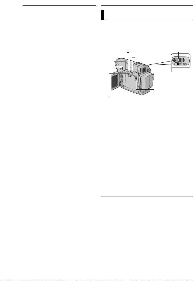
26 EN
To cancel Interval Shooting mode
Set “INT.SHOT” to “OFF” in step 1.
NOTES:
● It is recommended to use the AC Adapter as
the power supply instead of the battery pack.
(墌 pg. 13, 14)
● To distinguish between still images taken in
Interval Shooting mode and other still images, it is
recommended that you reset the file names before
shooting. (墌 pg. 28)
● Inter val Shooting will stop if the battery runs out of
power or the Memory Card becomes full.
● The function “Animation” in the provided software
“Digital Photo Navigator” can be used to create
movie files from the captured still images
(Windows
Macintosh, it is recommended that you use the
function “Creating a Slideshow From Still Images”
in the commercial software “QuickTime Pro”.
®
only). To create movie files with the
D.S.C. PLAYBACK
Normal Playback Of Images
Images shot with the camcorder are
automatically numbered, then stored in
numerical order in the memory card. You can
view the stored images, one at a time, much like
flipping through a photo album.
–
4/9
8
MENU
+
1 Load a memory card. (墌 pg. 17)
2 Set the VIDEO/MEMORY Switch to
“MEMORY”.
3 Set the Power Switch to “PLAY” while
pressing down the Lock Button located on the
switch.
● A stored image is displayed.
4 Press – to display the previous file. Press + to
display the next file.
NOTE:
Images shot and stored on the card with another
device with resolutions other than “640 x 480” and
“1024 x 768” will be displayed as thumbnails only.
These thumbnail images cannot be transferred to a
PC.
Playback Zoom (GR-D290 only)
Available only with the remote control.
(墌 pg. 24)
Lock Button
M
A
Power Switch
VIDEO/MEMORY
Page 81

D.S.C. PLAYBACK
EN 27
Auto Playback Of Images
You can run through all the images stored in
memory card automatically.
1 Perform steps 1 – 3 in “Normal Playback Of
Images” (墌 pg. 26).
2 Press 4/9 to start Auto Playback.
● If you press – during Auto Playback, files are
displayed in descending order.
● If you press + during Auto Playback, files are
displayed in ascending order.
3 To end Auto Playback, press 8.
Index Playback Of Files
You can view several different files stored in the
memory card at a time. This browsing capability
makes it easy to locate a particular file you want.
1 Perform steps 1 – 3 in “Normal Playback Of
Images” (墌 pg. 26).
2 Press INDEX. The
Index Screen appears.
3 Press + or – to move
the frame to the desired
file.
● Press – to display the
previous page. Press +
to display the next page.
4 Press MENU. The
selected file is displayed.
Selected file
2
1
4
5
8 9
7
Index number
3
6
Removing On-Screen Display
1 Perform steps 1 – 3 in “Normal Playback Of
Images” (墌 pg. 26).
2 Press MENU. The Menu Screen appears.
3 Press + or – to select “DISPLAY”, and press
MENU. The Sub Menu appears.
4 Press + or – to select “OFF”, and press
MENU. The operation mode indicator, folder/file
number and battery remaining power indicator
disappear.
● To display the indicators again, select “ON”.
Operation mode indicator
Folder/file number
100-0013
DISPLAYM E NU
50m
Battery remaining power indicator
OFF
ON
RETURN
Page 82
28 EN
ADDITIONAL FEATURES FOR D.S.C.
Dubbing Still Images Recorded On
A Tape To A Memory Card
Still images can be dubbed from a tape to a
memory card.
1 Load a cassette. (墌 pg. 16)
2 Load a memory card. (墌 pg. 17)
3 Set “SNAP/SLOW” to the desired mode.
(except “SLOW”, 墌 pg. 31, 32)
4 Set the VIDEO/MEMORY Switch to “VIDEO”.
5 Set the Power Switch to “PLAY” while
pressing down the Lock Button located on the
switch.
6 Set “ COPY” to “ON”.
(墌 pg. 31, 35)
7 Press 4/9 to start playback.
8 At the point you want to dub, press 4/9
again to engage Still Playback.
9 To dub the image, press SNAPSHOT.
● The “ ” indication appears during dubbing.
NOTES:
● To use Playback Special effects with a video
image you wish to dub, perform up to step 9 using
the remote control (provided with GR-D290 only).
(墌 pg. 24)
● Images are dubbed in 640 x 480 pixels.
Resetting The File Name
By resetting the file name, a new folder will be
made. The new files you are going to make will
be stored in the new folder. It is convenient to
separate the new files from previously made
files.
1 Perform steps 1 – 3 in “Normal Playback Of
Images” (墌 pg. 26).
2 Press MENU. The Menu Screen appears.
3 Press + or – to select “NO. RESET”, and
press MENU. The NO. RESET screen appears.
4 Press + or – to select “EXECUTE”, and press
MENU. The new folder (such as “101JVCGR”)
will be made and the file name of the next shot
starts from DVC00001.
NOTE:
If the file name reaches DVC09999, a new folder
(such as “101JVCGR”) will be made and the file
name will start again from DVC00001.
Protecting Files
The Protect mode helps prevent the accidental
erasure of files.
1 Perform steps 1 – 3 in “Normal Playback Of
Images” (墌 pg. 26).
2 Press MENU. The Menu Screen appears.
3 Press + or – to select “PROTECT”, and press
MENU. The Sub Menu appears.
To protect the currently displayed file
4 Press + or – to select
“CURRENT”, and press
MENU. The PROTECT
screen appears.
5 Slide the Power Zoom
Lever towards “T” or “W”
to select the desired file.
6 Press + or – to select
“EXECUTE”, and press
MENU.
● To cancel protection,
select “RETURN”.
● Repeat steps 5 and 6 for
all files you want to
protect.
To protect all files stored in the memory card
WT
4 Press + or – to select “PROT.ALL”, and press
MENU. The PROTECT screen appears.
5 Press + or – to select “EXECUTE”, and press
MENU.
● To cancel protection, select “RETURN”.
NOTES:
● If the “ ” mark appears, the currently displayed
file is protected.
● When the memory card is initialized or corrupted,
even protected files are deleted. If you do not want
to lose important files, transfer them to a PC and
save them.
CUR
PROTECTM E NURENT
PROT.ALL
CANC.ALL
RETURN
ROT ECTP
PROTECTED
RETURN
Page 83

To Remove Protection
Before doing the following, perform steps 1 – 3
in “Protecting Files”.
To remove protection from the currently
displayed file
4 Press + or – to select “CURRENT”, and press
MENU. The PROTECT screen appears.
5 Slide the Power Zoom Lever towards “T” or
“W” to select the desired file.
6 Press + or – to select “EXECUTE”, and press
MENU.
● To cancel selection, select “RETURN”.
● Repeat steps 5 and 6 for all files you want to
remove protection.
To remove protection from all files stored in
the memory card
4 Press + or – to select “CANC.ALL”, and press
MENU. The PROTECT screen appears.
5 Press + or – to select “EXECUTE”, and press
MENU.
● To cancel selection, select “RETURN”.
Deleting Files
Previously stored files can be deleted either one
at a time or all at once.
1 Perform steps 1 – 3 in “Normal Playback Of
Images” (墌 pg. 26).
2 Press MENU. The Menu Screen appears.
3 Press + or – to select “DELETE”, and press
MENU. The Sub Menu appears.
To delete the currently displayed file
4 Press + or – to select
“CURRENT”, and press
MENU. The DELETE
screen appears.
5 Slide the Power Zoom
Lever towards “T” or “W” to
select the desired file.
6 Press + or – to select
“EXECUTE”, and press
MENU.
● To cancel deletion, select
“RETURN”.
● Repeat steps 5 and 6 for
all files you want to delete.
NOTE:
If the “ ” mark appears, the selected file is
protected and cannot be deleted.
DELE TE M E NURENT
CUR
ALL
RETURN
ELETED
DELE TE?
EXECUTE
RETURN
ADDITIONAL FEATURES FOR D.S.C.
To delete all files stored in the memory card
EN 29
4 Press + or – to select “ALL”, and press
MENU. The DELETE screen appears.
5 Press + or – to select “EXECUTE”, and press
MENU.
● To cancel deletion, select “RETURN”.
NOTES:
● Protected files (墌 pg. 28) cannot be deleted. To
delete them, remove protection first.
● Once files are deleted, they cannot be restored.
Check files before deleting.
CAUTION:
Do not remove the memory card or perform any
other operation (such as turning off the camcorder)
during deletion. Also, be sure to use the provided
AC Adapter, as the memory card may be corrupted
if the battery becomes exhausted during deletion. If
the memory card becomes corrupted, initialize it.
(墌 pg. 30)
Setting Print Information (DPOF
Setting)
This camcorder is compatible with the DPOF
(Digital Print Order Format) standard in order to
support future systems such as automatic
printing. You can select one of the 2 print
information settings for images stored in the
memory card: “To Print All Still Images (One
Print For Each)” or “To Print By Selecting Still
Images And Number Of Prints”.
NOTES:
● If you load a memory card already set as shown
below in a printer compatible with DPOF, it will
make prints of the selected still images
automatically.
● To print images recorded on a tape, first dub them
to a memory card. (墌 pg. 28)
To Print All Still Images (One Print For Each)
1 Perform steps 1 – 3 in “Normal Playback Of
Images” (墌 pg. 26).
2 Press MENU. The Menu Screen appears.
3 Press + or – to select
“DPOF”, and press MENU.
The Sub Menu appears.
4 Press + or – to select
“ALL 1”, and press MENU.
The DPOF screen
appears.
CUR
DPOF M E NURENT
ALL 1
RESET
RETURN
Page 84
30 EN
5 Press + or – to select
“EXECUTE”, and press
ADDITIONAL FEATURES FOR D.S.C.
DPOF
MENU. The normal
playback screen appears.
● To cancel selection, select
“RETURN”.
ALL1 ?
EXECUTE
RETURN
To Print By Selecting Still Images And
Number Of Prints
1 Perform steps 1 – 3 in “To Print All Still
Images (One Print For Each)”.
2 Press + or – to select
“CURRENT”, and press
DPOF
MENU. The DPOF screen
appears.
3 Slide the Power Zoom
Lever towards “T” or “W” to
SHEETS
00
RETURN
W
select the desired file.
4 Press + or – to select the number indication
(00), and press MENU.
5 Select the number of
prints by pressing + to
DPOF
increase the number, or –
to decrease the number,
and press MENU.
● Repeat steps 3 through 5
for the desired number of
prints.
● The number of prints can be set up to 15.
● To correct the number of prints, select the image
again and change the number.
6 Press + or – to select
“RETURN”, and press
SHEETS
05
DPOF
MENU. The “SAVE?”
appears.
● If you did not change any
settings in step 3 through
5, the Menu Screen
reappears.
SAVE?
EXECUTE
CANCEL
7 Press + or – to select “EXECUTE” to save the
setting you have just made, and press MENU.
● To cancel selection, select “CANCEL”.
To Reset The Number Of Prints
1 Perform steps 1 – 3 in “To Print All Still
Images (One Print For Each)”.
2 Press + or – to select “RESET”, and press
MENU. The DPOF screen appears.
3 Press + or – to select “EXECUTE”, and press
MENU. The normal playback screen appears.
● To cancel selection, select “RETURN”.
● The number of prints is reset to 0 for all still
images.
CAUTION:
While performing the above, never disconnect
power, as this may cause the memory card to be
corrupted.
Initializing A Memory Card
T
You can initialize a memory card any time.
After initializing, all files and data stored in the
memory card, including those which have been
protected, are cleared.
1 Set the VIDEO/MEMORY Switch to
“MEMORY”.
2 Set the Power Switch to “PLAY” while
pressing down the Lock Button located on the
switch.
3 Press MENU. The Menu Screen appears.
4 Press + or – to select
“FORMAT”, and press
MENU. The FORMAT
screen appears.
5 Press + or – to select
“EXECUTE”, and press
MENU. The memory card
is initialized.
● When initialization is finished, “NO IMAGES
STORED” appears.
● To cancel initialization, select “RETURN”.
CAUTION:
Do not perform any other operation (such as
turning off the camcorder) during initialization.
Also, be sure to use the provided AC Adapter, as
the memory card may be corrupted if the battery
becomes exhausted during initialization. If the
memory card becomes corrupted, initialize it.
ORMATF
ERASE AL L
EXECUTE
RETURN
DATA ?EX IS TI NG
Page 85
Changing The Menu Settings
This camcorder is equipped with an easy-to-use,
on-screen menu system that simplifies many of
the more detailed camcorder settings.
(墌 pg.32–36)
MENU
1 For Video and D.S.C. Recording Menus:
● Set the VIDEO/MEMORY Switch to “VIDEO” or
“MEMORY”.
● Set the Power Switch to “M” while pressing down
the Lock Button located on the switch.
For Video Playback Menus:
● Set the VIDEO/MEMORY Switch to “VIDEO”.
● Set the Power Switch to “PLAY” while pressing
down the Lock Button located on the switch.
● For D.S.C. Playback Menus, refer to “D.S.C.
PLAYBACK” (墌 pg. 26).
2 Open the LCD monitor fully. (墌 pg. 18)
3 Press MENU. The Menu Screen appears.
4 Press + or – to select the desired function,
and press MENU. The selected function menu
appears.
Screen for Video and
D.S.C. Recording Menu
DIPE WA
R/F
E
F OF
W
– FA R ET
HIDE
– FA R
LADE
B
.WDE – FA R
B
C WI –
RNPE
O
W I –
NDE
I
PW
IDP S WI
L
E–
ORPE D WI –
O
RO
S WI
PE
– LL
C
S WI –RETH
UTPE
5 Setting procedure hereafter depends on the
selected function.
–
Lock Button
+
M
A
Power Switch
VIDEO/MEMORY
Screen for Video
Playback Menu
KC
RE
WO
E
DMSO N EO
NRET UR
ID O V E
DU
–STRE EO
OFONR–AT I NA R F
E C–MO D RE
OFCO Y P
F–
RCA KS BL N H
MENUS FOR DETAILED ADJUSTMENT
Menus without Sub Menus
v WIPE/FADER
(墌 pg. 41)
r PROGRAM AE
(墌 pg. 42)
p EXPOSURE
(墌 pg. 39)
u W. BALANCE
(墌 pg. 40)
1) Press + or – to select
the desired parameter.
● Example: r PROGRAM
AE Menu
2) Press MENU. Selection is complete. The
Menu Screen returns.
● Repeat the procedure if you wish to set other
function menus.
3) Press MENU. The Menu Screen closes.
Selected menu icon
blinks.
TWILIGHT
SEPIA
MONOTONE
CLASSIC FILM
STROBE
Menus with Sub Menus
m CAMERA (墌 pg. 32)
q MANUAL
(墌 pg. 32)
s SYSTEM (墌 pg. 33)
n
CAMERA DISPLAY
(墌pg. 34)
o DSC (墌 pg. 34)
t VIDEO (墌 pg. 35)
n VIDEO DISPLAY
(墌 pg. 36)
1) Press + or – to select
the desired function,
and press MENU. The
Sub Menu appears.
● Example: m CAMERA
Menu
2) Press + or – to select
the desired parameter.
3) Press MENU.
Selection is complete.
● Repeat the procedure if
you wish to set other
function menus.
4) Press MENU. The
Menu Screen returns.
● Repeat the procedure if
you wish to set other function menus.
5) Press MENU. The Menu Screen closes.
Selected menu icon
blinks.
Selected function
C
MODRE
NRETUR
C
MODRE
C
MODRE
SNAP/SLOW
NRETUR
EN 31
Selected
parameter
E RA ROG PM
A
OR S SP T
O W SN
OT I SP L GHT
ME A CA R
E
–
12ODU–D M SO N E TIB
25
– ZO M
O
x
FU– SNAP/SLOW LL
AG
– UP GA N
I
C
Sub Menu
ME A CA R
E
–
ME A CA R
E
–
12ODU–D M SO N E TIB
25
– ZO M
O
x
FU– LL
AG
– UP GA N
I
C
Page 86
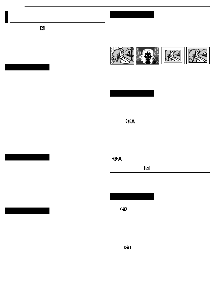
32 EN
MENUS FOR DETAILED ADJUSTMENT
Recording Menus
CAMERA
The “m CAMERA” settings are effective when
the Power Switch is set to both “A” and “M”.
However, the menu settings can be changed
only when the Power Switch is set to “M”.
[ ] = Factory-preset
REC MODE
[SP]: To record in the SP (Standard Play) mode
LP: Long Play—more economical, providing 1.5
times the recording time.
NOTES:
● Audio Dubbing (墌 pg. 46) and Insert Editing
(墌 pg. 46) are possible on tapes recorded in the
SP mode.
● If the recording mode is switched, the playback
picture will be blurred at the switching point.
● It is recommended that tapes recorded in the LP
mode on this camcorder be played back on this
camcorder.
● During playback of a tape recorded on another
camcorder, blocks of noise may appear or there
may be momentary pauses in the sound.
SOUND MODE
[12BIT]: Enables video recording of stereo
sound on four separate channels, and is
recommended for use when performing Audio
Dubbing. (Equivalent to the 32 kHz mode of
previous models)
16BIT: Enables video recording of stereo sound
on two separate channels. (Equivalent to the
48 kHz mode of previous models)
ZOOM
25X: When set to “25X” while using digital zoom,
the zoom magnification will reset to 25X since
digital zoom will be disengaged.
[100X]*: Allows you to use the Digital Zoom. By
digitally processing and magnifying images,
zooming is possible from 25X (the optical zoom
limit), to a maximum of 100X digital
magnification.
800X*: Allows you to use the Digital Zoom. By
digitally processing and magnifying images,
zooming is possible from 25X (the optical zoom
limit), to a maximum of 800X digital
magnification.
* Available only when the VIDEO/MEMORY Switch
is set to “VIDEO”.
SNAP/SLOW
[FULL]: Snapshot mode with no frame
NEGA: Nega mode
PIN-UP: Pin-Up mode
FRAME: Snapshot mode with frame
SLOW: Live Slow mode
[FULL] PIN-UP FRAMENEGA
For details on the procedure, refer to “Live Slow”
(墌 pg. 37) and “Snapshot (For Video
Recording)” (墌 pg. 38).
GAIN UP
OFF: Allows you to shoot dark scenes with no
picture brightness adjustment.
[AGC]: The overall appearance may be grainy,
but the image is bright.
AUTO : The shutter speed is automatically
adjusted. Shooting a subject in low or poor
lighting at slow shutter speed provides a brighter
image than in the AGC mode, but the subject’s
movements are not smooth or natural. The
overall appearance may be grainy. While the
shutter speed is being automatically adjusted,
“ ” is displayed.
MANUAL
The “q MANUAL” settings are effective only
when the Power Switch is set to “M”.
[ ] = Factory-preset
DIS
OFF: Disables the function.
[ON ]: To compensate for unstable images
caused by camera-shake, particularly at high
magnification.
NOTES:
● Accurate stabilization may not be possible if hand
shake is excessive, or depending on the shooting
condition.
● The “ ” indicator blinks or goes out if the
Stabilizer cannot be used.
● Switch off this mode when recording with the
camcorder on a tripod.
Page 87

5S
[OFF]: Disables 5-Second Recording.
5S: Enables 5-Second Recording. (墌 pg. 37)
Anim.: Allows you to record a few frames only.
By using an inanimate object and changing its
position between shots, you can record the
subject as though it is moving.
TELE MACRO
[OFF]: Disables the function.
ON: When the distance to the subject is less
than 1 m (3.3 ft), set “TELE MACRO” to “ON”.
You can shoot a subject as large as possible at a
distance of approx. 40 cm (1.4 ft).
NOTE:
Depending on the zoom position, the lens may go out
of focus.
WIDE MODE
[OFF]: Records with no change in the screen
ratio. For playback on a TV with a normal screen
ratio.
CINEMA* : Inserts black bands at the top and
bottom of the screen. The indicator appears.
During playback on wide-screen TVs, the black
bands at the top and bottom of the screen are
cut and the screen ratio becomes 16:9. When
using this mode, refer to your wide-screen TV’s
instruction manual. During playback/recording
on 4:3 TVs/LCD monitor/viewfinder, black bands
are inserted at the top and bottom of the screen
and the image appears like a letter boxed 16:9
movie.
SQUEEZE* : For playback on TVs with an
aspect ratio of 16:9. Naturally expands the
image to fit the screen without distortion. The
indicator appears. When using this mode,
refer to your wide-screen TV’s instruction
manual. During playback/recording on 4:3 TVs/
LCD monitor/viewfinder, the image is elongated
vertically.
* Available only when the VIDEO/MEMORY Switch
is set to “VIDEO”.
WIND CUT
[OFF]: Disengages the function.
ON : Helps cut down on noise created by
wind. The “ ” indicator appears. The quality of
the sound will change. This is normal.
MENUS FOR DETAILED ADJUSTMENT
SYSTEM
The “s SYSTEM” functions which are set when
the Power Switch is set to “M” are also applied
when the Power Switch is set to “PLAY”.
[ ] = Factory-preset
BEEP
OFF: Even though not heard while shooting,
shutter sound is recorded on the tape.
BEEP: The beep sounds when the power is
turned on or off, and at the beginning and end of
recording. It also activates the shutter sound
effect. (墌 pg. 25, 38)
[MELODY]: Instead of a beep, a melody sounds
when any operation is performed. It also
activates the shutter sound effect.
(墌 pg. 25, 38)
REMOTE
OFF: Disables the remote control operations.
[ON]: Enables the remote control operations.
For GR-D270 owners: It is recommended that
this function be set to “OFF” to prevent improper
operation.
DEMO MODE
OFF: Automatic demonstration will not take
place.
[ON]: Demonstrates certain functions such as
Program AE with special effects, etc., and can
be used to confirm how these functions operate.
Demonstration starts in the following cases:
● When the Menu Screen is closed after “DEMO
MODE” is turned “ON”.
● With “DEMO MODE” set to “ON”, if there is no
operation for about 3 minutes after the Power
Switch is set to “A” or “M”.
● Performing any operation during the
demonstration stops the demonstration
temporarily. If no operation is performed for more
than 3 minutes after that, the demonstration will
resume.
NOTES:
● If a cassette is in the camcorder, the
demonstration cannot be turned on.
● “DEMO MODE” remains “ON” even if the
camcorder power is turned off.
● If “DEMO MODE” remains “ON”, some functions
will not be available. After viewing demo, set to
“OFF”.
EN 33
Page 88
34 EN
[LCD]: The image is displayed on the LCD
monitor when the viewfinder is pulled out while
the LCD monitor is opened.
FINDER: The image is displayed in the
viewfinder when the viewfinder is pulled out
while the LCD monitor is opened.
EXECUTE: Resets all settings to the factorypreset.
[RETURN]: Does not reset all settings to the
factory-preset.
MENUS FOR DETAILED ADJUSTMENT
PRIORITY
CAM RESET
CAMERA DISPLAY
● The “n” (CAMERA DISPLAY) settings are
effective even when the Power Switch is set to
“A”. However, the menu settings can be changed
only when the Power Switch is set to “M”.
● The “n” (CAMERA DISPLAY) settings except
“BRIGHT” are effective only for shooting.
[ ] = Factory-preset
BRIGHT
墌 pg. 16, “Brightness Adjustment Of The
Display”
ON SCREEN
LCD: Keeps the camcorder’s display (except the
date, time and time code) from appearing on the
connected TV screen.
[LCD/TV]: Makes the camcorder’s display
appear on screen when the camcorder is
connected to a TV.
DATE/TIME
OFF: The date/time does not appear.
[AUTO]: Displays the date/time for approx. 5
seconds when the Power Switch is set from
“OFF” to “A” or “M”.
ON: The date/time is always displayed.
● The date indication can also be turned on/off by
pressing the DISPLAY Button on the remote
control (provided with GR-D290 only).
(墌 pg. 22, 43)
TIME CODE
[OFF]: Time code is not displayed.
ON: Time code is displayed on the camcorder
and on the connected TV. Frame numbers are
not displayed during recording. (墌 pg. 19)
LANGUAGE
[ENGLISH] / FRANÇAIS / ESPAÑOL /
The language setting can be changed.
(墌 pg. 15)
CLOCK ADJ.
墌 pg. 15, “Date/Time Settings”
DSC
[ ] = Factory-preset
QUALITY
[FINE] / STANDARD
The Picture Quality mode can be selected to
best match your needs. Two Picture Quality
modes are available: FINE ( ) and
STANDARD ( ) (in order of quality).
NOTE:
The number of storable images depends on the
selected picture quality as well as the composition
of the subjects in the images and the type of
memory card being used. (墌 pg. 25)
IMAGE SIZE
640 x 480 / [1024x768]
The Image Size mode can be selected to best
match your needs. (墌 pg. 25)
NOTE:
The setting can be changed only when the VIDEO/
MEMORY Switch is set to “MEMORY”.
Page 89
REC SELECT
[ (TAPE)]: When Snapshot recording is
performed with the VIDEO/MEMORY Switch set
to “VIDEO”, still images are recorded only onto
the tape.
/ (TAPE/CARD): When Snapshot
recording is performed with the VIDEO/
MEMORY Switch set to “VIDEO”, still images
are recorded not only onto the tape but also in
the memory card (640 x 480 pixels). In this
mode, the “SNAP/SLOW” selection in CAMERA
Menu is also applicable to memory card
recording.
INT.SHOT
[OFF]: Disables the function.
ON: Enables interval shooting. (墌 pg. 25)
INT.TIME
15SEC/30SEC/[1MIN]/2MIN/5MIN/10MIN
30MIN/60MIN
Allows you to select the shooting interval for
interval shooting. (墌 pg. 25)
/
MENUS FOR DETAILED ADJUSTMENT
Playback Menus
VIDEO
[ ] = Factory-preset
SOUND MODE and NARRATION
During tape playback, the camcorder detects the
sound mode in which the recording was made,
and plays the sound back. Select the type of
sound to accompany your playback picture.
According to the menu access explanation on
page 31, select “SOUND MODE” or
“NARRATION” from the Menu Screen and set it
to the desired parameter.
SOUND MODE
[STEREO ]: Sound is output on both “L” and
“R” channels in stereo.
SOUND L : Sound from the “L” channel is
output.
SOUND R : Sound from the “R” channel is
output.
NARRATION
[OFF]: Original sound is output on both “L” and
“R” channels in stereo.
ON: Dubbed sound is output on both “L” and “R”
channels in stereo. (墌 pg. 46)
MIX: Original and dubbed sounds are combined
and output in stereo on both “L” and “R”
channels.
REC MODE [SP] / LP
Allows you to set the video recording mode (SP
or LP) depending on your preference. It is
recommended you use “REC MODE” in VIDEO
Menu when using this camcorder as a recorder
during dubbing. (墌 pg. 43, 44)
COPY
[OFF]: When the SNAPSHOT button is pressed
during tape playback, the playback image
pauses and normal playback will resume after
approximately 6 seconds. (The still image is not
recorded.)
ON: Enables dubbing of images recorded on a
tape to a memory card. (墌 pg. 28)
EN 35
Page 90

36 EN
墌 pg. 21, “Blank Search”
MENUS FOR DETAILED ADJUSTMENT
BLANK SRCH
SYSTEM
Each setting is linked with “s SYSTEM”, which
appears when the Power Switch is set to “M”.
(墌 pg. 31)
● The parameters are the same as in the
description on page 33.
VIDEO DISPLAY
The “n” (VIDEO DISPLAY) settings are
effective only for video playback except
“BRIGHT”.
● The parameters (except “OFF” in ON SCREEN
settings) are the same as in the description
(CAMERA DISPLAY) on page 34.
[ ] = Factory-preset
BRIGHT
墌 pg. 16, “Brightness Adjustment Of The
Display”
ON SCREEN OFF / [LCD] / LCD/TV
When set to “OFF”, the camcorder’s display
disappears.
DATE/TIME [OFF] / AUTO / ON
When set to “AUTO”, the date/time are displayed
in the following cases:
● When playback starts. The camcorder displays
the date/time when scenes are recorded.
● When the date is changed during playback.
TIME CODE [OFF] / ON
墌 pg. 19, “Time Code”
LANGUAGE
[ENGLISH] / FRANÇAIS / ESPAÑOL /
The language setting can be changed.
(墌 pg. 15)
Page 91

FEATURES FOR RECORDING
EN 37
LED Light
LED Light can be used to
brighten the subject in the dark
place during video recording or
D.S.C. shooting.
1 Press LIGHT repeatedly to
change the setting.
OFF: Turns off the light.
ON: The light is on always. ( appears.)
AUTO: The light turns on automatically when
dark. ( appears.)
LED Light
2 Press the Recording Start/Stop Button to
start video recording or SNAPSHOT to shoot a
still image.
NOTES:
● Be careful not to point the LED Light directly to
eyes.
● If the light does not reach the subject, the NightAlive function will be activated, and makes it
possible to shoot the subject brighter.
● There is a difference in the brightness of the
images shot between the centre area which is
illuminated by the LED Light and the surrounding
areas (which will be darker).
● Since subjects are shot at a reduced shutter
speed when the LED Light setting is “ON”, they
will appear slightly blurred.
Live Slow
This feature is useful for recording or playing
back precious or hard-to-see moments at a slow
speed. Sound is recorded and played back in
real time.
1 Set the VIDEO/MEMORY Switch to “VIDEO”.
2 Set “SNAP/SLOW” to “SLOW”.
(墌 pg. 31, 32) The Live Slow indicator “ ”
appears.
3 Press SLOW during recording or playback.
● The moving pictures are divided into four
frames. They are recorded or played back for
1.5 seconds, and then normal recording or
playback resumes.
5-Second Recording
Record a vacation or an important event in 5second clips to keep the action moving. This
function is available only for video recording.
1 Set “5S” to “5S”. (墌 pg. 33)
● The “5S” indicator appears.
2 Press the Recording Start/Stop Button to
start recording, and after 5 seconds the
camcorder enters Record-Standby mode
automatically.
● Even if you press the Recording Start/Stop Button
again within 5 seconds after recording starts,
Record-Standby mode is not engaged.
3 To exit the 5S mode, select “OFF” in step 1.
To take a snapshot in the 5-second recording
mode
Instead of pressing the Recording Start/Stop
Button in step 2, select the desired Snapshot
mode in CAMERA Menu (墌 pg. 32), then press
SNAPSHOT. The camcorder records a 5second still. When “5S” is set to “Anim.”, this
function is not available.
NOTE:
When “5S” is set to “Anim.”, the 5-Second
Recording mode is not available. Animation
recording of a few frames only is taken instead.
Page 92

38 EN
FEATURES FOR RECORDING
Night-Alive
Makes dark subjects or areas even brighter than
they would be under good natural lighting.
Although the recorded image is not grainy, it may
look as if it is strobing due to the slow shutter
speed.
1 Set the Power Switch to “M”.
2 Press NIGHT so that the Night-Alive indicator
“ ” appears.
● The shutter speed is automatically adjusted to
provide up to 30 times sensitivity.
● “ ” appears beside “ ” while the shutter speed
is being automatically adjusted.
To deactivate Night-Alive
Press NIGHT again so that the Night-Alive
indicator disappears.
NOTES:
● During Night-Alive, the following functions or
settings cannot be activated and its indicator
blinks or goes out:
• Some modes of “Program AE With Special
Effects” (墌 pg. 42).
• “GAIN UP” in CAMERA Menu (墌 pg. 32).
• “DIS” in MANUAL Menu (墌 pg. 32).
● During Night-Alive, it may be difficult to bring the
camcorder into focus. To prevent this, use of a
tripod is recommended.
Snapshot (For Video Recording)
This feature lets you record still images that look
like photographs onto a tape.
1 Set the VIDEO/MEMORY Switch to “VIDEO”.
2 Set the Power Switch to “M”.
3 Set “SNAP/SLOW” to the desired mode.
(墌 pg. 31, 32) The Snapshot indicator “ ”
appears.
4 Press SNAPSHOT.
● There is the sound effect of a shutter closing.
● The “O” indication appears and a still image
will be recorded for approx. 6 seconds, then the
camcorder re-enters the Record-Standby mode.
● You can perform Snapshot also during recording.
A still image will be recorded for approx.
6 seconds, then the normal recording resumes.
● Regardless of the Power Switch position (“A” or
“M”), Snapshot recording takes place using the
selected Snapshot mode.
Motor Drive Mode
Keeping SNAPSHOT pressed in step 4 provides
an effect similar to serial photography. (Interval
between still images: approx. 1 second)
● The Motor Drive mode is disabled when “REC
SELECT” is set to “ / ”. (墌 pg. 35)
Manual Focus
The camcorder’s Full Range AF system offers
continuous shooting ability from close-up (as
close as approx. 5 cm (2") to the subject) to
infinity.
However, correct focus may not be obtained
depending on the shooting condition. In this
case, use the manual focus mode.
1 Set the Power Switch to
“M”.
2 Press FOCUS. The
manual focus indicator
appears.
3 Press + or – to focus on
a subject.
● When the focus level
cannot be adjusted any
further or closer, “ ” or “ ” will blink.
4 Press MENU. Focus adjustment is complete.
To reset to Auto Focus
Press FOCUS twice or set the Power Switch to
“A”.
Manual focus is recommended in situations
listed below.
● When two subjects overlap in the same scene.
● When illumination is low.*
● When the subject has no contrast (difference in
brightness and darkness), such as a flat, onecolor wall, or a clear, blue sky.*
● When a dark object is barely visible in the LCD
monitor or the viewfinder.*
● When the scene contains minute patterns or
identical patterns that are regularly repeated.
● When the scene is affected by sunbeams or light
reflecting off the surface of a body of water.
● When shooting a scene with a high-contrast
background.
* The following low-contrast warnings appear
blinking: , , and .
Manual focus
indicator
Page 93

Exposure Control Iris Lock
Manual exposure control is recommended in the
following situations:
● When shooting using reverse lighting or when the
background is too bright.
● When shooting on a reflective natural background
such as at the beach or when skiing.
● When the background is overly dark or the subject
is bright.
1 Set the Power Switch to “M”.
2 Set “p” to “MANUAL”. (墌 pg. 31)
● The exposure control indicator appears.
3 To brighten the image, press +. To darken the
image, press –. (maximum ±6)
● +3 exposure has the same effect as the backlight
compensation. (墌 pg. 40)
● –3 exposure has the same effect as when “r” is
set to “SPOTLIGHT”. (墌 pg. 42)
4 Press MENU. Exposure adjustment is
complete.
To return to automatic exposure control
Select “AUTO” in step 2. Or, set the Power
Switch to “A”.
NOTES:
● You cannot use the manual exposure control at
the same time when “r” is set to “SPOTLIGHT”
or “SNOW” (墌 pg. 42), or with the backlight
compensation.
● If the adjustment does not cause any visible
change in brightness, set “GAIN UP” to “AUTO”.
(墌 pg. 31, 32)
Like the pupil of the human eye, the iris
contracts in well-lit environments to keep too
much light from entering, and dilates in dim
environments to allow in more light.
Use this function in the following situations:
● When shooting a moving subject.
● When the distance to the subject changes (so its
size in the LCD monitor or the viewfinder
changes), such as when the subject is backing
away.
● When shooting on a reflective natural background
such as at the beach or when skiing.
● When shooting objects under a spotlight.
● When zooming.
1 Set the Power Switch to “M”.
2 Set “p” to “MANUAL”. (墌 pg. 31)
● The exposure control indicator appears.
3 Adjust zoom so that the subject fills the LCD
monitor or the viewfinder, then press and hold
MENU for over 2 seconds. The exposure control
indicator and the “ ” indication appear.
4 Press MENU. The “ ” indication changes to
“ ” and the iris is locked.
To return to automatic iris control
Select “AUTO” in step 2. Or, set the Power
Switch to “A”.
● The exposure control indicator and “ ”
disappear.
To lock the exposure control and the iris
After step 2, adjust the exposure by pressing +
or –. Then lock the iris in steps 3 and 4. For
automatic locking, select “AUTO” in step 2. The
exposure control and the iris become automatic.
FEATURES FOR RECORDING
EN 39
Page 94

40 EN
FEATURES FOR RECORDING
Backlight Compensation
Backlight compensation brightens the subject
quickly.
With simple operation, backlight compensation
feature brightens the dark subject portion by
increasing the exposure.
1 Set the Power Switch to “M”.
2 Press BACK LIGHT so that the Backlight
Compensation indicator “ ” appears.
To cancel Backlight Compensation
Press BACK LIGHT twice so that the “ ”
indicator disappears.
NOTE:
Using Backlight Compensation may cause the light
around the subject to become too bright and the
subject to become white.
Spot Exposure Control
Selection of a spot metering area enables more
precise exposure compensation. You can select
one of the three metering areas on the LCD
monitor/viewfinder.
1 Set the Power Switch to “M”.
2 Press BACK LIGHT twice so that the Spot
Exposure Control indicator “ ” appears.
● A spot metering area frame appears at the
centre of the LCD monitor/viewfinder.
3 Press + or – to select the desired spot
metering area frame.
4 Press MENU.
● Spot Exposure Control is engaged.
● Exposure is adjusted to make the brightness of
the selected area most appropriate.
To lock the iris
After step 3, press and hold MENU over 2
seconds. The “ ” indication appears and the
iris is locked.
To cancel Spot Exposure Control
Press BACK LIGHT once so that the “ ”
indicator disappears.
NOTES:
● You cannot use the Spot Exposure Control at the
same time with following functions.
• “SQUEEZE” in “WIDE MODE” (墌 pg. 33)
• “STROBE” in “PROGRAM AE” (墌 pg. 42)
• Digital Zoom (墌 pg. 19)
• Manual Exposure Control
● Depending on the shooting location and condition,
optimum result may not be attained.
White Balance Adjustment
The white balance refers to the correctness of
color reproduction under various lighting. If the
white balance is correct, all other colors will be
accurately reproduced.
The white balance is usually adjusted
automatically. However, more advanced
camcorder operators control this function
manually to achieve a more professional color/
tint reproduction.
To change the setting
Set “u” to the desired mode. (墌 pg. 31)
● The selected mode indicator except “AUTO”
appears.
[AUTO]: White balance is adjusted
automatically.
MWB: Adjust the white balance manually
when shooting under various types of lighting.
(墌 “Manual White Balance Adjustment”)
FINE: Outdoors on a sunny day.
CLOUD: Outdoors on a cloudy day.
HALOGEN: A video light or similar type of
lighting is used.
[ ] = Factory-preset
To return to automatic white balance
Set “u” to “AUTO”. (墌 pg. 31)
Or, set the Power Switch to “A”.
Page 95

Manual White Balance Adjustment
Adjust the white balance
manually when shooting
under various types of
lighting.
1 Set the Power Switch
to “M”.
White paper
2 Select “MWB” in
“u W.BALANCE” menu. (墌 pg. 31)
● The indication blinks slowly.
3 Hold a sheet of plain white paper in front of
the subject. Adjust zoom or position yourself so
that the white paper fills the screen.
4 Press and hold MENU until begins
blinking rapidly.
● When the setting is completed, resumes
normal blinking.
5 Press MENU twice. The Menu Screen closes
and the Manual White Balance indicator is
displayed.
NOTES:
● In step 3, it may be difficult to focus on the white
paper. In such a case, adjust focus manually.
(墌 pg. 38)
● A subject can be shot under various types of
lighting conditions indoors (natural, fluorescent,
candlelight, etc.). Because the color temperature
is different depending on the light source, the
subject tint will differ depending on the white
balance settings. Use this function for a more
natural result.
● Once you adjust white balance manually, the
setting is retained even if the power is turned off or
the battery removed.
Wipe Or Fader Effects
These effects let you make pro-style scene
transitions. Use them to spice up the transition
from one scene to the next.
Wipe or Fader works when video recording is
started or stopped.
1 Set the VIDEO/MEMORY Switch to “VIDEO”.
2 Set the Power Switch to “M”.
3 Set “v” to the desired mode. (墌 pg. 31)
● The WIPE/FADER menu disappears and the
effect is reserved.
● The selected effect indicator appears.
4 Press the Recording Start/Stop Button to
activate the Fade-in/out or Wipe-in/out.
FEATURES FOR RECORDING
To deactivate the selected effect
Select “OFF” in step 3. The effect indicator
disappears.
EN 41
NOTES:
● You can extend the length of a Wipe or Fader by
pressing and holding the Recording Start/Stop
Button.
● Some Wipe/Fader Effects cannot be used with
certain modes of Program AE with special effects.
(墌 pg. 42) In this case, the selected indicator
blinks or goes out.
WIPE/FADER
OFF: Disables the function. (Factory-preset)
FADER–WHITE: Fade in or out with a white
screen.
FADER–BLACK: Fade in or out with a black
screen.
FADER–B.W: Fade in to a color screen
from a black and white screen, or fade out from
color to black and white.
WIPE–CORNER: Wipe in on a black screen
from the upper right to the lower left corner, or
wipe out from lower left to upper right, leaving a
black screen.
WIPE–WINDOW: The scene starts in the
centre of a black screen and wipes in toward the
corners, or comes in from the corners, gradually
wiping out to the centre.
WIPE–SLIDE: Wipe in from right to left, or
wipe out from left to right.
WIPE–DOOR: Wipe in as the two halves of
a black screen open to the left and right,
revealing the scene, or wipe out and the black
screen reappears from left and right to cover the
scene.
WIPE–SCROLL: The scene wipes in from
the bottom to the top of a black screen, or wipes
out from top to bottom, leaving a black screen.
WIPE–SHUTTER: Wipe in from the centre
of a black screen toward the top and bottom, or
wipe out from the top and bottom toward the
centre leaving a black screen.
Page 96
42 EN
FEATURES FOR RECORDING
Program AE With Special Effects
1 Set the Power Switch to “M”.
2 Set “r” to the desired mode. (墌 pg. 31)
● The PROGRAM AE menu disappears and the
selected effect is activated.
● The selected effect indicator appears.
To deactivate the selected effect
Select “OFF” in step 2. The effect indicator
disappears.
NOTES:
● Program AE with special effects can be changed
during recording or during Record-Standby.
● Some modes of Program AE with special effects
cannot be used during Night-Alive.
● When a subject is too bright or reflective, a vertical
streak may appear (smear phenomenon). Smear
phenomenon tends to occur when “SPORTS” or
any mode of “SHUTTER 1/250 – 1/4000” is
selected.
● Some modes of Program AE with special effects
cannot be used with certain Wipe/Fader effects.
(墌 pg. 41) In this case, the selected indicator
blinks or goes out.
PROGRAM AE
OFF: Disables the function. (Factory-preset)
SHUTTER 1/60: The shutter speed is fixed
at 1/60th of a second. Black bands that usually
appear when shooting a TV screen become
narrower.
SHUTTER 1/100: The shutter speed is
fixed at 1/100th of a second. The flickering that
occurs when shooting under a fluorescent light
or mercury-vapor lamp is reduced.
SHUTTER 1/250/ SHUTTER 1/500/
SHUTTER 1/1000*/ SHUTTER 1/2000*/
SHUTTER 1/4000*: These settings allow fast-
moving images to be captured one frame at a
time, for vivid, stable slow-motion playback by
fixing shutter speed variables. Use these
settings when an automatic adjustment does not
work well, using SPORTS mode. The faster the
shutter speed, the darker the picture becomes.
Use the shutter function under good lighting
conditions.
SPORTS
(Variable Shutter Speed: 1/250 – 1/4000):
This setting allows fast-moving images to be
captured one frame at a time, for vivid, stable
slow-motion playback. The faster the shutter
speed, the darker the picture becomes. Use the
shutter function under good lighting conditions.
SNOW: Compensates for subjects that may
otherwise appear too dark when shooting in
extremely bright surroundings such as in the
snow.
SPOTLIGHT: Compensates for subjects
that may otherwise appear too bright when
shooting under extremely strong direct lighting
such as spotlights.
TWILIGHT: Makes evening scenes look
more natural. White Balance (墌 pg. 40) is
automatically set to “ ”, but can be changed to
your desired setting. When Twilight is chosen,
the camcorder automatically adjusts the focus
from approx. 10 m (32 ft) to infinity. From less
than 10 m, adjust the focus manually.
SEPIA: Recorded scenes have a brownish
tint like old photos. Combine this with the
Cinema mode (墌 pg. 33, “WIDE MODE”) for a
classic look.
MONOTONE: Like classic black and white
films, your footage is shot in B/W. Used together
with the Cinema mode (墌 pg. 33, “WIDE
MODE”), it enhances the “classic film” effect.
CLASSIC FILM*: Gives recorded scenes a
strobe effect.
STROBE*: Your recording looks like a
series of consecutive snapshots.
MIRROR*: Creates a mirror image on the
right half of the screen, juxtaposed to the normal
image on the other half.
* Available only when the VIDEO/MEMORY Switch
is set to “VIDEO”.
Page 97
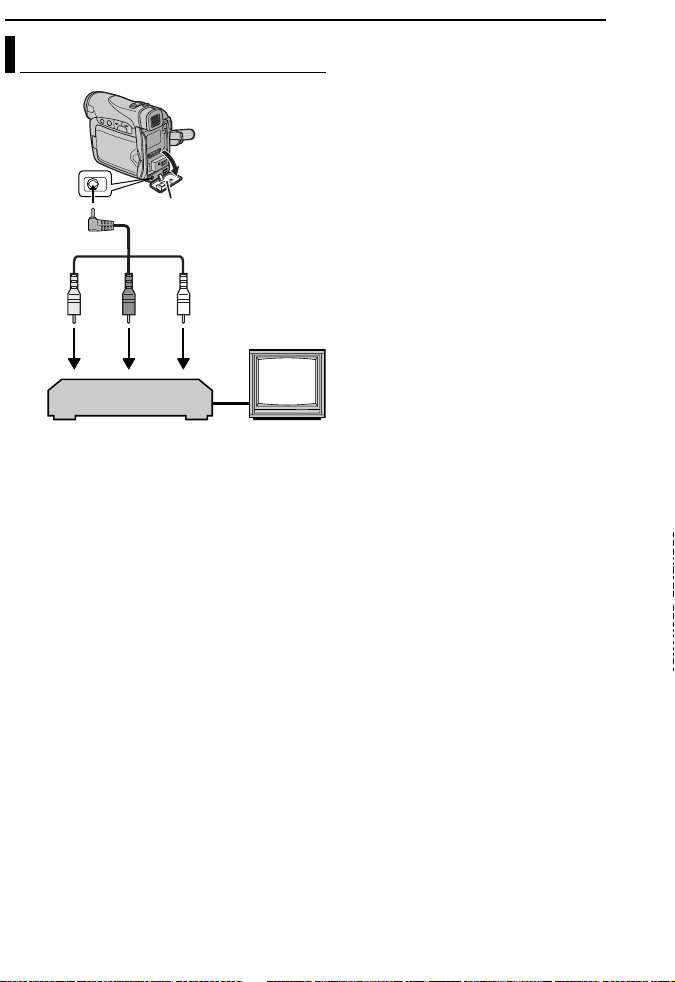
Dubbing To A VCR
To AV
connector
A Yellow to VIDEO IN
B Red to AUDIO R IN
C White to AUDIO L IN
Open the cover.
Audio/Video cable
(provided)
213
VCR
TV
EDITING
To use this camcorder as a player
EN 43
1 Following the illustrations, connect the
camcorder and the VCR’s input connectors.
2 Start playback on the camcorder. (墌 pg. 20)
3 At the point you want to start dubbing, start
recording on the VCR. (Refer to the VCR’s
instruction manual.)
4 To stop dubbing, stop recording on the VCR,
then stop playback on the camcorder.
NOTES:
● It is recommended to use the AC Adapter as
the power supply instead of the battery pack.
(墌 pg. 14)
● To choose whether or not the following displays
appear on the connected TV
• Date/time
Set “DATE/TIME” to “AUTO”, “ON” or “OFF”.
(墌 pg. 31, 36) Or, press DISPLAY on the
remote control (provided with GR-D290 only) to
turn on/off the date indication.
• Time code
Set “TIME CODE” to “OFF” or “ON”.
(墌 pg. 31, 36)
• Indications other than date/time and time code
Set “ON SCREEN” to “OFF”, “LCD” or “LCD/
TV”. (墌 pg. 31, 36)
Page 98

44 EN
EDITING
Dubbing To Or From A Video Unit
Equipped With A DV Connector
(Digital Dubbing)
It is also possible to copy recorded scenes from
the camcorder onto another video unit equipped
with a DV connector. Since a digital signal is
sent, there is little if any image or sound
deterioration.
To DV IN/OUT
Core filter
Video unit equipped with DV connector
To use this camcorder as a player
1 Make sure all units are turned off.
2 Connect this camcorder to a video unit
equipped with a DV input connector using a DV
cable as shown in the illustration.
3 Start playback on the camcorder. (墌 pg. 20)
4 At the point you want to start dubbing, start
recording on the video unit. (Refer to the video
unit’s instruction manual.)
5 To stop dubbing, stop recording on the video
unit, then stop playback on this camcorder.
DV cable (optional)
To DV IN/OUT
NOTES:
● It is recommended to use the AC Adapter as
the power supply instead of the battery pack.
(墌 pg. 14)
● If a blank portion or disturbed image is played
back on the player during dubbing, the dubbing
may stop so that an unusual image is not dubbed.
● Even though the DV cable is connected correctly,
sometimes the image may not appear in step 4. If
this occurs, turn off the power and make
connections again.
● If “Playback Zoom” (墌 pg. 24) or “Playback
Special Effects” (墌 pg. 24) is attempted or
SNAPSHOT is pressed during playback, only the
original playback image recorded on the tape is
output from the DV IN/OUT connector.
● When using a DV cable, be sure to use the
optional JVC VC-VDV204U DV cable.
To use this camcorder as a recorder
1 Make sure all units are turned off.
2 Connect this camcorder to a video unit
equipped with a DV output connector using a DV
cable as shown in the illustration.
3 Set “REC MODE” to “SP” or “LP”. (墌 pg. 32)
4 Set the camcorder’s Power Switch to “PLAY”.
5 Press the Recording Start/Stop Button to
engage the Record-Pause mode.
● The “ ” indication appears on the screen.
DV IN
6 Start playback on the player.
7 At the point you want to start dubbing, press
the Recording Start/Stop Button to start
dubbing. The indication rotates.
8 Press the Recording Start/Stop Button again
to stop dubbing. The indication stops
rotating.
9 Press 8 to return to the normal playback
mode.
NOTE:
Digital Dubbing is performed in the sound mode
recorded on the original tape, regardless of the
current “SOUND MODE” setting. (墌 pg. 32)
Page 99
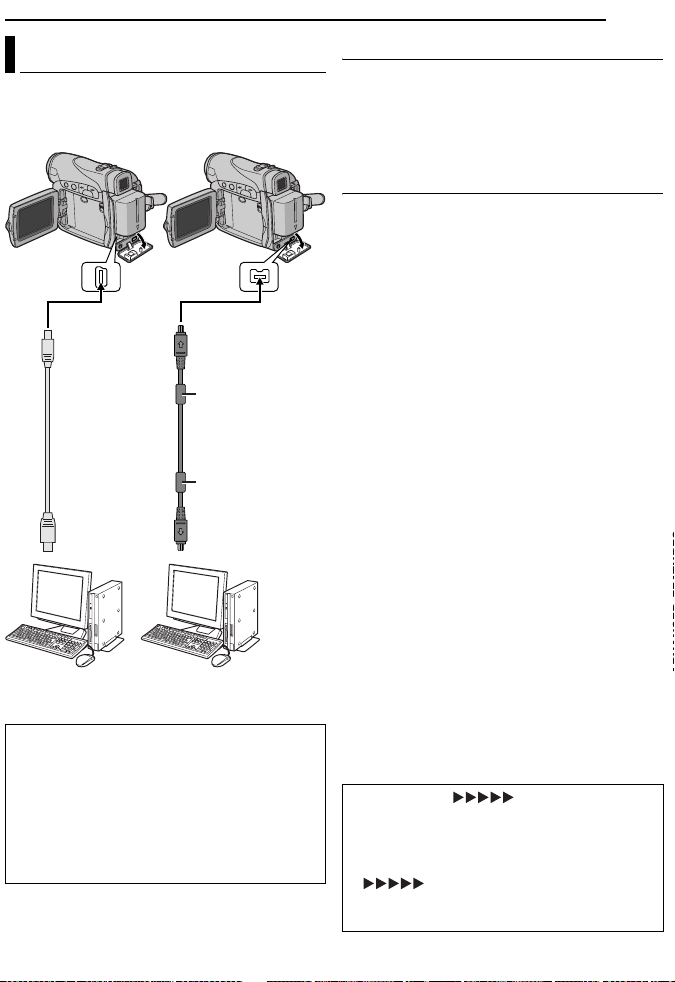
Connection To A Personal Computer
[A] Using USB cable
To U SB
USB cable
(provided)
To USB
connector
PC
When connecting the camcorder to a PC
using a DV cable, make sure to follow the
procedure below. Connecting the cable
incorrectly may cause malfunctions to the
camcorder and/or the PC.
● Connect the DV cable first to the PC, and then
to the camcorder.
● Connect the DV cable (plugs) correctly
according to the shape of the DV connector.
[B] Using DV cable
OR
To DV IN/OUT
Core filter
DV cable
(optional)
Core filter
To DV connector
PC with DV connector
EDITING
EN 45
[A] Using USB cable
It is possible to do the following things:
● Transfer still images stored on a memory card
to a PC.
● Transfer still/moving images recorded on a
tape to a PC.
[B] Using DV cable
It is also possible to transfer still/moving images
to a PC with a DV connector by using the
provided software, software equipped with the
PC or commercially available software.
If you are using a Windows® XP, you can use
Windows® Messenger to conduct video
conferences over the Internet, using a
camcorder. For details, refer to the help for the
Windows® Messenger.
NOTES:
● Refer to “SOFTWARE INSTALLATION AND PC
CONNECTION GUIDE” for the bundled software
and drivers.
● It is recommended to use the AC Adapter as
the power supply instead of the battery pack.
(墌 pg. 14)
● Never connect the USB cable and the DV
cable simultaneously to the camcorder.
Connect only the cable you wish to use to the
camcorder.
● When using a DV cable, be sure to use the
optional JVC VC-VDV206U or VC-VDV204U DV
cable depending on the type of DV connector
(4 or 6 pins) on the PC.
● If the PC connected to the camcorder via the USB
cable is not powered, the camcorder does not
enter the USB mode.
● The date/time information cannot be captured into
the PC.
● Refer to the instruction manuals of the PC and
Software.
● The still images can also be transferred to a PC
with a DV connector-equipped capture board.
● The system may not work properly depending on
the PC or capture board you are using.
“USB” and/or “” appears on the
LCD monitor while the PC is accessing data in
the camcorder or the camcorder is
transferring a file to the PC.
NEVER disconnect the USB cable while
“ ” is displayed on the LCD
monitor since this can result in product
damage.
Page 100

46 EN
EDITING
Audio Dubbing (GR-D290 only)
The audio track can be customized only when
recorded in the 12-BIT and SP modes.
(墌 pg. 32)
● Use the provided remote control.
Speaker
START/
STOP
REW
INSERT
PAUSE
PLAY
STOP
A.DUB
1 Play back the tape to locate the point where
editing will start, then press PAU SE (9).
2 While holding A. DUB (D) on the remote
control, press PA US E (9). The “9D” and “MIC”
indicators appear.
3 Press PLAY (U), then begin “narrating”.
Speak into the microphone.
● To pause dubbing, press PAU SE (9).
4 To end Audio Dubbing, press PAUS E (9),
then STOP (8).
To hear the dubbed sound during playback
Set “NARRATION” to “ON” or “MIX”.
(墌 pg. 31, 35)
NOTES:
● Sound is not heard from the speaker during Audio
Dubbing.
● When editing onto a tape that was recorded at
12-BIT, the old and new soundtracks are recorded
separately.
● If you dub onto a blank space on the tape, the
sound may be disrupted. Make sure you only edit
recorded areas.
● If feedback or howling occurs during TV playback,
move the camcorder’s microphone away from the
TV, or turn down the TV’s volume.
● If you change from 12-BIT to 16-BIT in midrecording and then use the tape for Audio
Dubbing, it is not effective from the point where
16-BIT recording began.
● During Audio Dubbing, when the tape moves to
scenes recorded in the LP mode, scenes
recorded in 16-BIT audio or a blank portion, Audio
Dubbing stops.
Stereo Microphone
Insert Editing (GR-D290 only)
You can record a new scene into a previously
recorded tape, replacing a section of the original
recording with minimal picture distor tion at the in
and outpoints. The original audio remains
unchanged.
● Use the provided remote control.
NOTES:
● Before performing the following steps, make sure
that “TIME CODE” is set to “ON”. (墌 pg. 31, 36)
● Inser t Editing is not possible on a tape recorded in
the LP mode or on a blank portion of a tape.
1 Play back the tape, locate the Edit-Out point
and press PAU SE (9). Confirm the time code at
this point. (墌 pg. 19)
2 Press REW (
located, then press PA US E (9).
3 Press and hold INSERT (I) on the remote
control, then press PA US E (9). The “9I”
indicator and the Time Code (min.:sec.) appear
and the camcorder enters Insert-Pause mode.
4 Press START/STOP to begin editing.
● Confirm the insert at the time code you checked in
step 1.
● To pause editing, press START/STOP. Press it
again to resume editing.
5 To end Insert Editing, press START/STOP,
then STOP (8).
NOTES:
● Program AE with special effects (墌 pg. 42) can
be used to spice up the scenes being edited
during Insert Editing.
● During Insert Editing, the date and time
information changes.
● If you perform Insert Editing onto a blank space on
the tape, the audio and video may be disrupted.
Make sure you only edit recorded areas.
● During Insert Editing, when the tape moves to
scenes recorded in the LP mode or a blank
portion, Insert Editing stops. (墌 pg. 50)
3
) until the Edit-In point is
 Loading...