

Page 1
SCHEMATIC DIAGRAMS
DIGITAL VIDEO CAMERA
YF075B20055
GR-D270US, GR-D271US, GR-D275US,
GR-D290US, GR-D295US
CD-ROM No.SML200505
GR-D270US2M, GR-D271US2M, GR-D275US2M[M5D2S5]
GR-D290US2M, GR-D295US2M[M5D2S7]
There are two types of mechanisms used in this model.
While the previous SERVICE MANUAL <No.YF075> features existing <YMA0029 series>, this SERVICE MANUAL <No.YF075B>
features <YMB0051 series>.The<YMB0051 series> is a new type of DVC mechanism.
For the distinguishing methods, refer to “How to distinguish the two types”.
For disassembling methods, refer to the SERVICE MANUAL <YF081>.
Regarding service information other than these sections, refer to the service manual No. YF075 (GR-D290US).
<How to distinguish the two types>
1.Distinction by checking the Rating Label
If the new mechanism <YMB0051 series> is used, “2” is marked in the upper right part of the Rating Label.
2.Distinction by checking the actual model
Open the CASSETTE COVER, and check the CASSETTE
HOUSING.
If the model uses the new mechanism <YMB0051 series>,
“PUSH” is marked in the near right part of the CASSETTE
HOUSING surface.
COPYRIGHT © 2005 Victor Company of Japan, Limited
2
Fig.1
Refer to Fig.1
2
PUSH
Fig.2
No.YF075B
2005/5
Page 2
CHARTS AND DIAGRAMS
NOTES OF SCHEMATIC DIAGRAM
Safety precautions
The Components indentified by the symbol are
critical for safety. For continued safety, replace safety
critical components only with manufacturer's recommended parts.
1. Units of components on the schematic diagram
Unless otherwise specified.
1) All resistance values are in ohm. 1/6 W, 1/8 W (refer to
parts list).
Chip resistors are 1/16 W.
K: KΩ(1000Ω), M: MΩ (1000KΩ)
2) All capacitance values are in µF, (P: PF).
3) All inductance values are in µH, (m: mH).
4) All diodes are 1SS133, MA165 or 1N4148M (refer to parts
list).
Note: The Parts Number, value and rated voltage etc. in
the Schematic Diagram are for references only.
When replacing the parts, refer to the Parts List.
2. Indications of control voltage
AUX : Active at high.
AUX or AUX(L) : Active at low.
!
4. Voltage measurement
1) Regulator (DC/DC CONV) circuits
REC : Colour bar signal.
PB : Alignment tape (Colour bar).
— : Unmeasurable or unnecessary to measure.
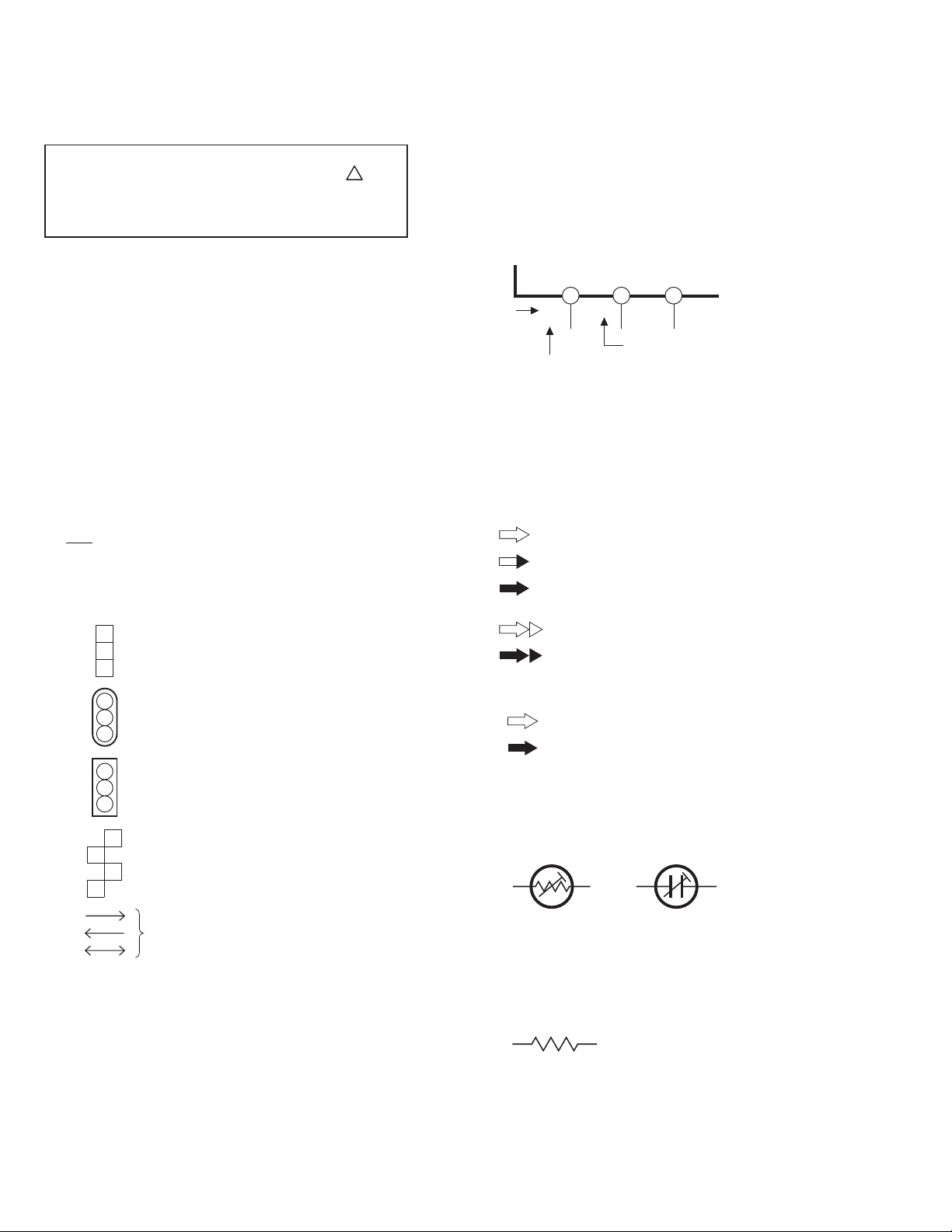
2) Indication on schematic diagram
Voltage indications for REC and PB mode on the schematic diagram are as shown below.
REC mode
12 3
2.5
(5.0)
PB mode
1.8
PB and REC modes
(Voltage of PB and REC modes
are the same)
Note: If the voltages are not indicated on the schematic
diagram, refer to the voltage charts.
5. Signal path Symbols
The arrows indicate the signal path as follows.
NOTE : The arrow is DVC unique object.
Playback signal path
Playback and recording signal path
3. Interpreting Connector indications
1
2
Removable connector
3
1
2
Wire soldered directly on board
3
1
Non-removable Board connector
2
3
1
2
4
Board to Board
3
Connected pattern on board
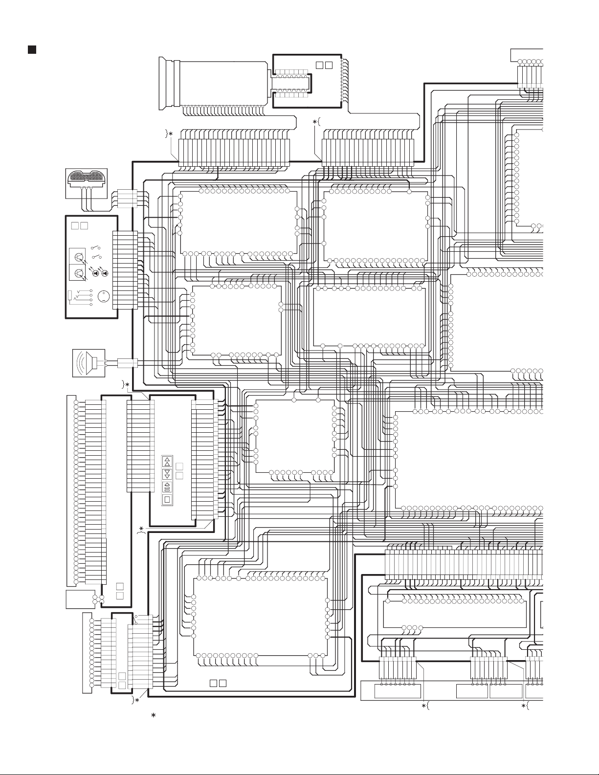
The arrows indicate signal path
Note: For the destination of each signal and further line
connections that are cut off from the diagram,
refer to "BOARD INTERCONNECTIONS"
Recording signal path
(including E-E signal path)
Capstan servo path
Drum servo path
(Example)
R-Y
Playback R-Y signal path
Y
Recording Y signal path
6. Indication of the parts for adjustments
The parts for the adjustments are surrounded with the circle
as shown below.
7. Indication of the parts not mounted on the circuit board
“OPEN” is indicated by the parts not mounted on the circuit
board.
R216
2-1(No.YF075B)
OPEN
Page 3
CIRCUIT BOARD NOTES
1. Foil and Component sides
1) Foil side (B side) :
Parts on the foil side seen from foil face (pattern face)
are indicated.
2) Component side (A side) :
Parts on the component side seen from component face
(parts face) indicated.
rts location are indicated by guide scale on the circuit board.
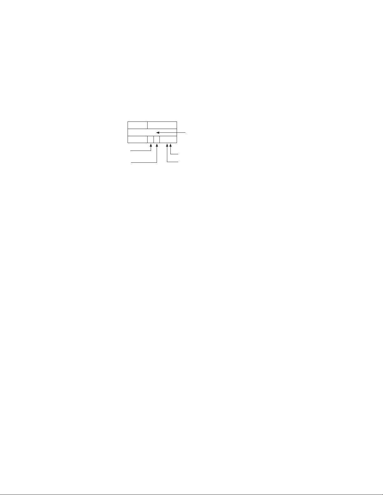
2. Parts location guides
Parts location are indicated by guide scale on the circuit board.
LOCATION
IC
Category : IC
Horizontal “A” zone
Vertical “6” zone
(A : Component side)
D : Discrete component)
B : Foil side
C : Chip component
REF No.
IC101 B C 6 A
Note: For general information in service manual, please
refer to the Service Manual of GENERAL INFORMATION Edition 4 No. 82054D (January 1994).
(No.YF075B)2-2
Page 4
6 RECH
L MUTE
7 DIAL OFF
DSYIO6
M
R
0
0
BOARD INTERCONNECTION
OP BLOCK
YTU94074-24
YTU94077-24
9 GND
8 OP_THRMO
7 F_PTR_AD
6 F_VCC
5 F_LED
4 FOCUS01
3 FOCUS04
2 FOCUS03
INT MIC
07
FRONT
W_Sens
RCU
EXT_MIC IN
12
EJECT
12
MONI SW
Light_LED
LITHIUM
BATTERY
CN701
17
16
15
14
13
12
11
10
9
8
7
6
5
4
3
2
1
SPEAKER
YTU94074-20
YTU94077-20
1VCOMH
2VCOML
3VCL
4C41N
5C41P
6VGH
7C31N
8C31P
9VGL
10C23N
11C23P
12C22N
13C22P
14C21N
15C21P
16VDDA
17VFB
18DRV
19VSS
20ND
21VDD
22VDD1
23NC
24VSS1
LCD(MONITOR) MODULE
25VCOIN
26PDO
27VA[R]
28VA[G]
29VA[B]
30DE
31HS
32VS
33POL
34VDD
35NPC
36VSSD
37HWRESETZ
38GCL
39GDA
40GCS
CN7602
BL
15VCOM
14VIDR
13VIDG
12VIDB
11HCK1
10HCK2
9HST
8VREF
7DWN
6VCK
5VST
4EN
LCD(C-VF) MODULE
3SLEEP
2VDD
1VSS
YTU94074-16
YTU94077-16
CN114
1INT/R
2INT_GND
3INT_GND
4INT/L
CN103
1EJT_SW
2LITHIUM
3MONI_SW
4LAMP_ON
5REG_4.8V
6REG_4.8V
7GND
8GND
9GND
10EM_GND
11EXT/R
12EXT/L
13EM_DET_L
14EM_GND
15IR_RMC
16REG_4.8V
17IR_OUT
1SPK+
2SPK-
CN112
1
2
3
4
5
6
7
8
9
10
11
12
13
14
15
16
17
18
19
20
CN7601
YTU94074-26
MONITOR
60
12
14
CN7002
13
CN7001
12
11
10
9
8
7
6
5
VF
4
3
2
1
08
CN302
1REG_3.1V
2REG_3.1V
3REG_4.8V
4REG_4.8V
5LCD_CTL
6REG_4.8V
7AU_LV_OUT
8LCD_CS
9AU_LV_CLK
10VDCVF
11HDCVF
12MON_G
13MON_R
14MON_B
15HRP
16M_RVS
17GND
18GND
19GND
20GND
DECK OPE
YTU94077-26
16VF_SW
15GND
14GND
13GND
12VFREG4.8
11VF_9V
10VF_SLEEP
9EN
8VST
7VCK
6HST
5HCK2
4HCK1
3CVF_B
2CVF_G
1CVF_R
CN108
CN102
1 FOCUS02
IR_OUT
LENS_LED
F/Z_CS
GND
REG_4.8V
REG_3.1V
VOI_CLK
OPE
30
CN301
VOI_OUT
26
25
24
23
22
21
20
19
18
17
16
15
14
13
12
11
10
9
8
7
6
5
4
3
2
1
FOCUSO2
VOI_IN
EXT/R
EXT/L
EM_GND
GND
INT/R
INT/L
INT_GND
SPK+
SPK-
GND
GND
GND
GND
M_RVS
HRP
MON_B
MON_R
MON_G
HDCVF
VDCVF
AU_LV_CLK
LCD_CS
AU_LV_OUT
REG_4.8V
LCD_CTL
REG_3.1V
REG_3.1V
REG_4.8V
REG_4.8V
GND
GND
MENU_SW
KEY_C
GND
KEY_A
VOI_IN
LCD_G
LCD_B
LCD_R
HRP2
HDCVF
VDCVF
HRP
DCO0
FOCUSO3
IRIS_CS
VOI_OUT
DCO1
FOCUSO4
IRIS_PS
REG_4.8V
AU_LV_CLK
10
11
12
13
14
15
16
17
18
19
20
21
22
23
24
25
26
VOI_CLK
DCO2
REC_ADJ
1
2
3
4
5
6
7
8
9
DCO3
CN110
10 ZOOM02
F_VCC
FOCUSO0
OP DRV
ATF_GAIN
DOLRCK2
REG_3.1V
AUDIO
AU_LV_OUT
V_OUT
C_OUT
DYO1
10 MAIN
NOTE1: The number of patch cords ( ) are indicated by interconnected.
12 ZOOM04
11 ZOOM03
ZOOM2
NOSIG_LV
DOMCK2
SHUT_ATT
Y_OUT
DYO2
13 ZOOM01
ZOOM3
DUMP_CTL
DOBCK2
AUDIO_CS
CLK27B
DYO3
OUTH
15 HGVcc+
14 NC
ZOOM1
ZOOM4
ASPECT
DODAT2
BUZZER
PD_L
S2_DET
VIDEO
CLK27A
17 HGVss-
16 HGout+
HGVcc+
IRIS_MCK
VDIRS
AODAT
S_SHUT
A_MUTE
VIF_CS
INH
INV
MAIN IF
18 HGout-
HGOut+
HDIRS
AILRCK
AU_SIG/R
L_MUTE
GND
REG_3.1V
REG_4.8V
HDCVF
VDCVF
MON_R
MON_G
MON_B
VC0
20 DRIVE-
19 NC
HGVss-
FSPLLCTL
AIMCK
AU_SIG/L
EM_DET_L
VC1
7654321
8
VDD
22 Z_PTR_AD
21 DRIVE+
DRIVE-
HGOut-
DRIVE+
T_F_V_RST
M_REG4.8
CAM_OUT
CAM_CLK
PBVCOCTL
M_VCOCTL
AIBCK
AIDAT/AIDAT2
MONI/VF
EN
VF_9V
VC3
VC2
BLKA
GND
9
1011121314
RG GND
SUB
24 Z_LED
23 Z_VCC
Z_LED
VD_F/Z
F/Z_MCK
VST
VCK
BLKB
VL
REG_15V
BLKC
ZOO
20
V4H1V1V2Vout
V3
CCD
8 DIAL_PB
9 PHOTO_F
10 ZOOM_SW
11 GND
12 REG_3.1V
CN109
H2
TEST
YTU94074-20
YTU94077-20
CN101
GND
19
20 GND
CAM_CLK
CAM_OUT
T_F_V_RST
15 GND
16 GND
17 CCD_OUT
18 GND
V3
V2
V1
V4
14 GND
CCD_-7.5V
13 CCD_15V
11 RG
12 CCD_15V
H2
8H2
9H1
10 SUB
H1
RG
SUB
CDS/TG
REG_3.1V
CPOB
ID
HDIN
REG_4.8V
REG-CCD
PBLK
VF_CTL
CLKI
REG_CS
ADIN0
ADIN1
REGRTC_CLK
REGRTC_OUT
ADIN2
V_BATT
VDIN
REG_15V
GND
LITHIUM
REG_3.1V
REG
REG_12V
VFREG4.8
MREG_4.8
LCD_R
LCD_G
REG_12V
LCD_B
HRP2
RGB_CTL
VF_CS
AU_LV_CLK
AU_LV_OUT
HST
CVF_G
HCK2
CVF_R
S_IN_L
V_F_V_RST
REG_4.8V
REG_3.1V
REG_2.5V
REG_1.7V
OUTV
DOT_CLK
OSD_VD
PSCTL
GND
CVF_B
ANA_IN_H
ASPECT
HCK1
OSD_HD
REG_15V
REG_1.7V
CN402
REG_2.5V
CN104
CN401
M_UNREG
2V2
3V3
4V4
5 CCD_CTL
6 CCD_-7.5V
7 CCD_-7.5V
GND
CCD_15V
CCD_OUT
REG_4.8V
REG-CCD
ADIN4
ADIN6
ADIN3
ADIN5
ADIN7
LIT_3V
D_GAIN
AL_3.1V
CHRG_EVR
CAP_PWR
DRUM_ERR
CAP_ERR
ADP_DC
DRUM_PWR
EJT_SW
MONI_SW
LAMP_ON
IR_RMC
EM_DET_L
IR_OUT
CCD_CTL
T_F_V_RST
REG_3.1V
GND
CAPT_REQ
DSC_WKUP
123456789
35 P/R_GND GND
36 P/R_GND GND
37 CAM_SW_C
38 CAM_SW_B
39 CAM_SW_A
40 DEW_SENS
P/R_GND
REG_2.5V
REG_3.1V
2F1S1F
2S
HEAD
1V1
TG_CS
CDS_CS
ADIN8
ADIN9
DOMCK2
VDDSC
FLDDSC
CLKDSC
DOBCK2
I_MTR
SYS_RSTL
BATT_+
BATT_+
TVSEL
AU_LV_CLK
MXDT_OUT
DSC_STS
33 MONI_CHG
34 P/R GND GND
REC_CLK
REG_4.8V
1
P/R_GND21F31S4P/R_GND5P/R_GND62F72S8P/R_GND
DOLRCK2
DODAT2
FLSH_RST
DSC_RST
DSC_CLK
DSC_DT_OUT
DSC_DT_IN
DSC_CS
MXDT_OUT
DSC_STS
CAPT_REQ
DSC_WKUP
P_MEDIA
DSC_RST
26 REG_4.8V
VREF_1.1
AGC_OUT
Z_PTR_AD
FLSH_RST
24 P/R_GND GND
25 REC_CLK
REC_CTL
CN403
LOADING
F_PTR_AD
OP_THRMO
IRIS_CS
IRIS_PS
22 REC_ADJ
23 REC_DATA
REC_ADJ
NOSIG_LV
MOTOR
VOI_IN
21 REF_CLK
ATF_GAIN
1
P/R_GND
F/Z_CS
20 REG_2.5V
2
LOAD_REV
VF_SW
VF_SLEEP
AU_LV_OUT
DSC_DT_IN
DSC_CS
DSC_DT_OUT
DSC_CLK
10111213141516171819202122232425262728293031323334
27 REG_4.8V
28 REG_4.8V
29 REG_4.8V
30 REG_3.1V
31 REG_3.1V
32 REG_3.1V
VRB_ATF
REF_CLK
VRB_AGC
REC_DATA
PRE/REC
YTU94074-8
YTU94077-8
HDDSC
LENS_LED
VOI_OUT
VOI_CLK
19 NOSIG_LV
ATFI
DUMP_CTL
4
3
DEW_SENS
LOAD_FWD
DSCIO6
DSCIO7
CAM_CLK
CAM_OUT
VC3
VIF_CS
16 P/R_GND GND
17 ATFI
18 P/R_GND GND
RECH
ENV_OUT
6
5
CAM_SW_B
CAM_SW_A
ROTARY
ENCODER
SW
DSCIO5
MMC_CD
VC2
14 ATF_GAIN
15 VRB_ATF
PBH
8
P/R_GND7CAM_SW_C
DSCIO4
A16
SHUT_ATT
VC1
13 VRB_AGC
HID1
CN404
VDIN
HDIN
ID
CPOB
PBLK
CLKI
ADIN0
ADIN1
ADIN2
ADIN3
ADIN4
ADIN5
ADIN6
ADIN7
ADIN8
ADIN9
DSCIO3
DSCIO2
A15
A14
AUDIO_CS
VC0
BLKA
11 AGC_OUT
12 P/R_GND GND
HID3
MONI_CHG
S_SHUT
DSCIO0
DSCIO1
D15
A13
PD_L
BUZZER
BLKB
BLKC
8 EVN_OUT
9 VREF_1.1
10 P/R_GND GND
YTU94
YTU94
AODAT
DSYIO7
D14
A_MUTE
OSD_HD
7 REC_CTL
8
D_COIL_W9COIL_COM10D_PG-11GND
D
2-3(No.YF075B)
Page 5

26
CN109
PBH
DSCIO5
ZOOM UNIT
6 DIAL_AUTO
7 DIAL_OFF
8 DIAL_PB
9 PHOTO_F
10 ZOOM_SW
11 GND
12 REG_3.1V
4GND
5 DIAL_MANU
2GND
3 PWR_LED
1 TRIG_SW
WT
YTU94074-12
YTU94077-12
CN113
JIG CONNECTOR
21 SYS_TMS
22 SYS_TDI
23 SYS_TDO
24 AL_3VSYS
25 JLIP_TX
26 TXD2
27 NC
28 NC
29 ENV_OUT
30 ATFI
31 DISCRI
32 HST
33 MON_R
34 GND
35 V_OUT
36 CVF_B
37 CVF_G
38 NC
39 DSC_DBG
40 MVD
20 KENTO
17 CVF_R
18 GND
19 NC
13 MON_B
14 MON_B
15 GND
16 HRP
12 FS_PLL
9NC
10 MAIN_VCO
11 HID
8 I_MTR
5 IF_TX
6 JLIP_RX
7 RXD2
4 SYS_RSTL
3 SYS_TRSTL
2 SYS_TCK
1 EXMOD_1
DSCIO4
MMC_CD
DSCIO3
A16
SHUT_ATT
VDIN
HDIN
ID
CPOB
PBLK
CLKI
ADIN0
ADIN1
ADIN2
ADIN3
ADIN4
ADIN5
ADIN6
ADIN7
ADIN8
ADIN9
DSCIO2
A15
A14
BUZZER
AUDIO_CS
DSCIO1
TSR
FRP
SPA
OMT
XINT
MFLD
CDAS
CDRE
DSP_RST
DSP_CS
CDWE
ADDT15
CPU_WAIT
ADDT14
ADDT13
ADDT12
ADDT11
ADDT10
ADDT09
ADDT08
ADDT07
ADDT06
ADDT05
ADDT04
ADDT03
ADDT02
ADDT01
ADDT00
CLK27SEL
FSPLLCTL
M_VCOCTL
IRIS_MCK
PBVCOCTL
VD_F/Z
F/Z_MCK
HDIRS
VDIRS
REC_CTL
REC_CLK
REF_CLK
REC_DATA
VRB_ATF
PARAGON
AILRCK
AIMCK
AIBCK
D15
AODAT
DSYIO7
A_MUTE
D14
DSYIO6
D13
L_MUTE
DSYIO5
MVD
DSYIO4
AIDAT/AIDAT2
DSYIO3
DSYIO2
DSYIO1
DSYIO0
DSCO7
DSCO6
DSCO5
DSCO4
DSCO3
DSCO2
INV
DSCO1
INH
DSCO0
CLK27A
DSYO7
OUTH
DSYO6
DYO3
DSYO5
DSC
D1
D8
D6
D9
D11
D12
VF_CS
D10
RGB_CTL
VF_CTL
D7
REG_CS
D5
REGRTC_CLK
REGRTC_OUT
V_BATT
D4
CHRG_EVR
EM_OE
D0
USB_INT
EM_WE
USB_CS
D2
D3
SPA
XINT
I_MTR
LIT_3V
D_GAIN
AL_3.1V
SYS_RSTIL
DYO2
DSYO4
TSR
DYO1
DSYO3
USB_RST
FRP
DYO0
DSYO2
USB_WKUP
USB_DP
OMT
DCO3
DSYO1
MFLD
DCO2
DSYO0
USB_DN
DCO1
DSP_RST
CLK240
MMC_DOUT
CLK27B
CDAS
DCO0
AIDAT/AIDAT2
MMC_CLK
MMC_DIN
MMC_CS
SD_WP
MMC_CD
USBDOWN
DSC_DBG
TXD2
RXD2
CDRE
DSP_CS
TPA+
REG_4.8V
GND
CDWE
TPA-
REG_3.1V
TPB+
ADDT15
CPU_WAIT
DSYO4
DSYO1
DSYO2
ADDT12
CLK240
ADDT11
DSYO0
ADDT10
ADDT09
ADDT08
DSYO3
ADDT07
USB_DN
ADDT06
TPB-
ADDT13
ADDT14
DSYO6
DSYO5
USB_UP
USB_WKUP
USBDOWN
ADDT05
ADDT04
DSYO7
USB_RST
USB
ADDT03
DSCO0
USB_INT
ADDT02
DSCO1
EM_WE
ADDT01
DSCO2
EM_OE
ADDT00
S_SHUT
DSCIO0
A13
PD_L
CPU
PBH
VC1
BLKB
VC2
BLKA
VC0
DOT_CLK
BLKC
PSCTL
OSD_HD
27282930313233343536373839
_
4 HID1 HID
5 PBH
6 RECH
7 REC_CTL
8 EVN_OUT
9 VREF_1.1
10 P/R_GND GND
11 AGC_OUT
12 P/R_GND GND
13 VRB_AGC
14 ATF_GAIN
HID3
HID1
MONI_CHG
LOAD_FWD
LOAD_REV
CN404
8
P/R_GND
ARY
ODER
W
DRUM MOTOR CAPSTAN MOTOR SENSOR
YTU94074-8
YTU94077-8
ANA_IN_H
2 DUMP_CTL
3 HID3
D_PG-
S2_DET
S_IN_L
40
1 P/R_GND GND
D_COIL_W
COIL_COM
OUTV
OSD_VD
YTU94105-40
YTU94077-40
D_COIL_V
D_COIL_U
CN405
1
D_PFG+2D_FG-3D_COIL_U4D_COIL_U5D_COIL_V6D_COIL_V7D_COIL_W8D_COIL_W9COIL_COM10D_PG-11GND
HID3
DEW_SENS
CN105
CN408
C_FG+
D_PFG+
D_FG-
YTU94074-11
YTU94077-11
CAM_SW_B
CAM_SW_A
123456789
39 M_REG4.8
40 M_REG4.8
C_FG-
CAM_SW_C
38 M_REG4.8
C_COIL_V
C_COIL_W
HID
MONI_CHG
36 M_REG3.1
37 M_UNREG
C_COIL_U
RECH
35 M_REG3.1
HG_U+
C_FRB
DRUM_REF
L_FRB
DRUM_PG
MDA_PS
CAP_FG
CAP_REF
10111213141516171819202122232425262728293031323334353637383940
26 CAP_PWR
27 DRUM_PWR
28 DRUM_PWR
29 DRUM_PWR
30 DRUM_ERR
31 GND
32 GND
33 GND
34 GND
HG_W-
HG_W+
HG_V+
HG_BS-
HG_U-
HG_V-
HG_BS+
LD_ON
24 CAP_PWR
25 CAP_PWR
1
C_COIL_U2C_COIL_U3HG_W+4HG_V+5HG_U+6C_COIL_W7C_COIL_W8HG_BS-9HG_BS+10HG_U-11HG_V-12HG_W-13C_COIL_V14C_COIL_V15GND16C_FG+17C_FG-18MDA_2.9V
23 CAP_ERR
T_RL+
CN406
22 GND
T_RL-
MIC1
MIC2
DRUM_FG
19 CAP_FG
20 CAP_REF
21 GND
S_RL+
S_RL-
YTU94074-18
YTU94077-18
MIC3
17 MDA_PS
18 C_FRB
GND
MDA_2.9V
S_SENS
REC_SAFE
15 L_FRB
16 LD_ON
P/R_GND
14 DURM_REF
TAPE_LED
13 DURM_FG
M_REG4.8
CAS_SW
12 DURM_PG
M_REG3.1
M_UNREG
E_SENS
11 MIC3
T_REEL
S_REEL
9 MIC1
10 MIC2
DRUM_ERR
DRUM_PWR
REEL_VCC
7 S_SENS
8 REC_SAFE
CAP_PWR
3
GND4T_RL+5T_RL-6S_RL_-7REEL_VCC8S_RL+9E_SENS10MIC111MIC212REC_SAFE13MIC314MDA_2.9V15GND16S_SENS
KEY_A
5 TAPE_LED
6 E_SENS
CAP_REF
CAP_ERR
MDA
1
CAS_SW2TAPE_LED
KEY_C
4 CAS_SW
CAP_FG
MENU_SW
LCD_CTL
2 T_REEL
3 S_REEL
C_FRB
MDA_PS
YTU94074-16
YTU94077-16
MECHA
[Z32]
LCD_CS
1 REEL_VCC
LD_ON
04
HID
ATFI
VREF_1.1
VRB_AGC
AGC_OUT
DSCO3
DSCO6
DSCO7
DSCO4
DSCO5
D2
D1
D3
D0
USB_CS
USB
EXTCLK
EXTACCES
EXTREQ
EXTFPP
TRIG_SW
PHOTO_F
CLK27SEL
ZOOM_SW
ADP_L
M_RVS
T_BATT
P_DET
D_BATT
CDS_CS
YTU94105-40
YTU94077-40
L_FRB
S_REEL
DRUM_FG
DRUM_PG
DRUM_REF
PRE/MDA IF
(Page2-5)
PRE/MDA
MVD
DSYIO0
DSYIO1
D4
D5
EXDATA1
EXDATA0
DIAL_OFF
DIAL_AUTO
TG_CS
T_REEL
TVSEL
DSYIO2
D6
EXDATA2
DIAL_PB
USBDOWN
AL_3VSYS
KENTO
IF_TX
JLIP_TX
JLIP_RX
EXMOD_1
SYS_TCK
SYS_TDI
SYS_TDO
SYS_TMS
SYS_TRSTL
DISCRI
DSYIO3
DSYIO4
D8
D7
EXDATA4
EXDATA3
PWR_LED
DIAL_MANU
MAIN_VCO
DSYIO5
DSYIO6
D9
EXDATA5
EXDATA6
FS_PLL
EXTFRP
EXTREQ
EXTDATA0
EXTDATA1
EXTDATA2
EXTACCES
DSCIO5
DSCIO3
DSCIO2
DSCIO4
DSYIO7
DSCIO0
DSCIO1
A13
A14
D12
D10
D15
D13
D11
D14
REG_4.8V
REG_1.7V
EXDATA7
1 P_MEDIA
2 GND
3 REG_3.1V
4 MMC_CS
5 MMC_DIN
6 MMC_CLK
7 MMC_CD
8 MMC_DOUT
9 SD_WP
10 GND
11 GND
12 GND
CN111
10 C_OUT
11 GND
12 Y_OUT
13 GND
14 GND
15 GND
16 GND
17 GND
18 GND
19 D_BATT
20 T_BATT
21 BATT_CHK
22 BATT_+
23 BATT_+
24 BATT_+
25 BATT_+
26 ADP_L
27 GND
28 GND
29 GND
30 GND
31 ADP_DC
32 ADP_DC
33 ADP_DC
34 ADP_DC
35 ADP_DC
36 BATT_+
37 BATT_+
38 BATT_+
39 BATT_+
40 BATT_+
CN107
EXTDATA4
EXTDATA3
DSCIO6
DSCIO7
A15
A16
GND
1 TPA+
2 TPA-
3 TPB+
4 TPB-
5 GND
6 AU_SIG/L
7 AU_SIG/R
8 P_DET
9 V_OUT
EXTDATA5
EXTDATA6
CLK27B
OUTV
OSD_VD
REG_4.8V
REG_3.1V
REG_2.5V
REG_1.7V
HDDSC
VDDSC
CN901
12
11
10
9
8
11
7
12
6
13
5
4
10
3
14
2
1
YTU94074-12
YTU94077-12
1
2
3
4
5
6
7
8
9
10
11
12
13
14
15
16
17
18
19
20
21
22
23
24
25
26
27
28
29
30
31
32
33
34
35
36
37
38
39
40
YTU94105-40
YTU94077-40
EXTCLK
EXTDATA7
GND
FLDDSC
CLKDSC
09
8765432
Victor
CU-MMC04
MultiMediaCard
CN902
REAR
BATT_TERM.
+
SD
8MB
T
UNIT
MULTIDC JACK
1
9
ٕ
-
y10554001a_rev0.1
(No.YF075B)2-4
Page 6

PRE/MDA(PRE/MDA IF) SCHEMATIC DIAGRAM
CN401
QGF0508F1-40X
UNDER CONTACT
38
39
40
DEW_SENS
CAM_SW_A
CAM_SW_B
PRE/MDA(PRE/MDA IF)
30
36
37
P/R_GND
CAM_SW_C
34
35
P/R_GND
P/R_GND
32
33
REG_3.1V
MONI_CHG
30
31
REG_3.1V
REG_3.1V
28
29
REG_4.8V
REG_4.8V
26
27
REG_4.8V
REG_4.8V
TO MAIN IF(CN104)
[PRE/REC]
21
22
23
24
25
P/R_GND
REC_CLK
RECCADJ
REC_DATA
REF_CLK
19
20
REG_2.5V
NOSIG_LV
17
18
ATFI
P/R_GND
15
16
P/R_GND
VRB_ATF
13
14
VRB_AGC
ATF_GAIN
11
12
P/R_GND
AGC_OUT
9
10
P/R_GND
VREF_1.1
7
8
REC_CTL
ENV_OUT
6
RECH
5
PBH
4
HID1
3
HID3
1
2
P/R_GND
DUMP_CTL
LOAD_FWD
LOAD_REV
DEW_SENS
CAM_SW_A
CAM_SW_B
CAM_SW_C
P/R_GND
8
CN402
QGF0543F1-08X
UNDER CONTACT
P/R_GND
1234567
P/R_GND
1F
P/R_GND
1S
2F
TO HEAD
2S
P/R_GND
8
CN404
QGF0543F1-11X
UNDER CONTACT
CN403
QGF0532F2-08X
UNDER CONTACT
P/R_GND
1234567
TO LOADING MOTOR,
ROTARY ENCODER SW
NOTES: 1. For the destination of each signal and further line connections that are cut off from this diagram, refer to "BOARD INTERCONNECTIONS".
2. The parts with marked ( ) is not used.
2-5(No.YF075B)
D_PFG+
1
D_FG-
2
Page 7

1
P/R_GND
CN408
QGF0508F1-40X
UNDER CONTACT
38
39
40
M_REG4.8
M_REG4.8
M_REG4.8
36
37
M_REG3.1
M_UNREG
34
35
GND
M_REG3.1
33
GND
32
GND
31
GND
29
30
DRUM_ERR
DRUM_PWR
27
28
DRUM_PWR
DRUM_PWR
25
26
CAP_PWR
CAP_PWR
TO MAIN IF(CN105)
[MDA]
20
21
22
23
24
GND
GND
CAP_ERR
CAP_PWR
CAP_REF
19
CAP_FG
18
C_FRB
16
17
LD_ON
MDA_PS
15
L_FRB
GND
S_SENS
13
14
DRUM_FG
DRUM_REF
MDA_2.9V
MIC3
11
12
MIC3
DRUM_PG
REC_SAFE
MIC2
10
MIC2
MIC1
9
MIC1
E_SENS
7
8
S_SENS
REC_SAFE
S_RL+
REEL_VCC
5
6
E_SENS
TAPE_LED
S_RL-
T_RL-
3
4
S_REEL
CAS_SW
T_RL+
GND
1
2
T_REEL
REEL_VCC
TAPE_LED
CAS_SW
D_PFG+
D_FG-
D_COIL_U
D_COIL_U
1X
TACT
123456789
D_COIL_V
D_COIL_V
D_COIL_W
D_COIL_W
COIL_COM
D_PG-
10
GND
11
CN405
QGF0543F1-18X
UNDER CONTACT
HG_W+
HG_V+
C_COIL_U
C_COIL_U
123456789
HG_U+
C_COIL_W
C_COIL_W
HG_BS-
TO CAPSTAN MOTORTO DRUM MOTOR
16151413121110
CN406
QGF0508F1-16X
UNDER CONTACT
HG_U-
HG_V-
HG_BS+
HG_W-
C_COIL_V
C_COIL_V
GND
101112131415161718
987654321
TO SENSER
MDA_2.9V
C_FG-
C_FG+
y30324001a_rev0.1
ONS".
(No.YF075B)2-6
Page 8

D
PRE/MDA CIRCUIT BOARD
<01>PRE/MDA
LYB10028-001B
COMPONENT SI
TL1605
TL1619
5
8
R1636
IC1702
C1702
CN405
R1611
R1610
R1616
R1622
R1707
R1708
R1637
C1633
TL1617
TL1612
TL1618
TL1613
R1705
R1704
R1702
R1701
R1706
C1701
D1603
R1712
R1711
R1635
CN406
4
1
R1703
R1710
R1709
Q1601
16 1
CN404
111118
C1617
R1634
C1631
TL1602
CN408
C1635C1636
IC1601
C1620
R1621
C1632
D1604
R1614
C1619
R1629
C1634
C1618
TL1610
R1601
C1603
L1601
R1625
33
16
R1602
C1626
C1627
C1625
C1624
TL1609
C1602
F1601
F1602
32
TL1601
17
C1606
R1604
R1603
C1605
L1602
R1620
C1614
R1613
49
64
R1617
R1612
4
1
TL1606TL1607
TL1608
48
1
C1615
R1632
C1616
R1633
C1621
C1629
C1630
C1607
C1622
C1623
5
IC1701
8
1 40
R1624
C1628
TL
NOTES: 1. For the destination of each signal and further line connections that are cut off from this diagram, refer to "BOARD INTERCONNECTIONS".
2. The parts with marked ( ) is not used.
2-7(No.YF075B)
Page 9

32
L1602
CAUTION :
FOR CONTINUED PROTECTION AGAINST FIRE HAZARD, REPLACE ONLY WITH SAME TYPE AND RATED FUSE(S).
ATTENTION :
POUR UNE PROTECTION PERMANENTE CONTRE LES RISQUE D'INCENDE,
!
ENT SIDE(A)
CN402
18
R3504
R3505
R3506
R3507
1626
1627
1625
1624
TL1601
R1624
33
C3512C3513C3514
32
IC3501
17
REMPLACER LES FUSIBLES PAR UNAAUTRE DE MEME TYPE ET DE MEME TENSION.
C3508C3511
R3503R3508
16
C3509 C3510
D1602
C1601
CN403
18
C1628
17
609
R1620
C1606
R1604
R1603
C1605
2
40 1 40
TL1620
48
C3516 C3526
R3514
R3513
C3515
Q3501
C3532
C3531
C3533
R3515
C3534
49
C3517
R3510
C3527
R3509
C3518 C3519
C3520
L3503
C3521
C3522 C3525
C3523
C3501
L3502
64
C3524
C3503
L3505
R3502
CN401
1
C3505
C3507
C3504
R3501
C3502
L3504
C3506
R3512
R3511
54
IC3502
13
C3528
C3530
L3501
TL3501
ONS".
(No.YF075B)2-8
Page 10

CCD, OPE, MONITOR CIRCUIT BOARDS
CAUTION :
FOR CONTINUED PROTECTION AGAINST FIRE HAZARD, REPLACE ONLY WITH SAME TYPE AND RATED FUSE(S).
ATTENTION :
POUR UNE PROTECTION PERMANENTE CONTRE LES RISQUE D'INCENDE,
!
REMPLACER LES FUSIBLES PAR UNAAUTRE DE MEME TYPE ET DE MEME TENSION.
<02>CCD
LYB20013-001D
COMPONENT SIDE(A)
Q5002
R5002
1
CN5001
20
<06>MONITOR
LYB10019-001C
C5003
<04>OPE
LYB10019-001C
FOIL SIDE(B)
126
CN301
TESTG
CN302
120
C302
S305
COMPONENT SIDE(A)
C301
S303
S304
R302
TEST
R303
R304
S301S302
S306
IC5001
C5001
L5002
7
R5001
Q5001
L5001
C5002C5004 C5007
8
C5005
C5006
TEST
1
14
COMPONENT SIDE(A)
ZP1-5
D7602
R7615
ZP1-17
ZP1-19
ZP1-3
ZP1-6
L7501
C7605
ZP2-4
C7604
CN7601
ZP2-1ZP2-2ZP2-3
ZP2-5
Q7502
R7503
Q7501
R7613
C7610
ZP2-13
C7609
C7611
ZP2-14
Q7504
C7612
ZP2-16
CN7602
ZP2-15
D7603
R7614
ZP2-9
D7605
C7607
ZP2-10
C7501
R7502
D7604
C7608
ZP2-12
ZP2-11
L7502
F7501
120
ZP1-1
C7606
R7501
1 40
C7603
ZP2-6
ZP2-8
ZP2-7
C7619
R7612
C7502
Q7503
R7601
C7620
ZP2-25 ZP2-26
L7603
C7503
R7606
R7603
R7602
L7604
L7601
C7621
R7608
R7605
C7614
C7622
C7617
ZP2-17
C7613
54
R7609
R7611
ZP2-37
R7607
IC7602
C7601
C7615
ZP2-35
T7501
C7618
13
R7610
L7602
R7604
R7504
ZP2-22
C7602
C7504C7505
2-9(No.YF075B)
Page 11

Page 12

Victor Company of Japan, Limited
AV & MULTIMEDIA COMPANY CAMCORDER CATEGORY 12, 3-chome, Moriya-cho, kanagawa-ku, Yokohama, kanagawa-prefecture, 221-8528, Japan
(No.YF075B)
Printed in Japan
VPT
 Loading...