

JVC DZ-VCA1SE Service Manual
MICRO HD CAMERA
VICTOR COMPANY OF JAPAN, LIMITED
VIDEO DIVISION
S40894
DZ-VCA1SE
No. 86536
DZ-VCA1SE
SPECIFICATIONS
* Design and specifications subject to change without notice.
Camera head section
■Image sensing device : 1/3-inch IT-CCD (410,000 pixels)
■Shooting system : 4-CCD new dual green system
■Colour separation optical
system : 1/3 type F1.4 3-colour separation prism
■Number of effective pixels : 768 (horizontal) x 494 (vertical), 380,000 pixels
■Camera output : 19 pins
■Lens mount : Special mount (C mount form, flange back: 28.0 mm)
■Dimensions : Camera head; 59 (W) x 70 (H) x 79 (D) mm
■Weight : Camera head; 230 g (0.51 lbs.) (not including
■Classification : Type BF
Camera control unit section
■Number of scanning lines : 1125 (980 effective)
■Scanning system : 2:1 interlace
■Scanning frequency : 33.75 kHz (horizontal), 60 Hz (vertical)
■Aspect ratio : 4:3
■Horizontal resolution (center) : More than 800 TV lines (Y signal)
■Vertical resolution (center) : More than 650 TV lines (Y signal)
■S/N : 52 dB
■Sensitivity : F5.6, 2000 lx
■Minimum subject illuminance : 10 lx (F1.6 + 12 dB, 1/30 shutter, 50% level)
■Sync system : Internal sync/external sync
■External sync signal input : Composite video signal of 1 Vp-p or composite sync
■Colour bar : Full colour bar
■Contour correction : Horizontal dual-edged (9-step variable)
■Electronic shutter speed : 1/30 s, 1/60 s (normal), 1/100 s (flicker-free),
■Video output
• R/G/B signal : 0.7 Vp-p, 75 ohms for each (no sync), BNC
• Y/PB/PR Y : 1 Vp-p, 75 ohms (including sync)
• Sync signal : HD; BNC x 1 (TTL)
PB : 0.7 Vp-p, 75 ohms (including sync)
PR : 0.7 Vp-p, 75 ohms (including sync)
(2-3/8” x 2-13/16” x 3-1/8”)
(not including insulating rubber covers)
insulating rubber covers)
signal of ±0.3 Vp-p, 75 ohms, BNC x 1
Vertical dual-edged (9-step variable)
1/175 s, 1/250 s, 1/375 s, 1/500 s, 1/1000 s,
1/2000 s
connector x 3 (one for each)
VD, BNC x 1 (TTL)
C. SYNC; BNC x 1
(±0.3 Vp-p, 75 ohms, compliant with HDTV
standard ITU-R Rec. 709)
■SCSI Interface : 50 pin mini x 2
■Camera input : 20 pins
■Date indication : Menu system
■Time indication : Menu system,
■Power supply : DC 12 V, 1.3 A XLR 4 pins, AA-V112E AC
■Power consumption : 18 W
■Operating environment :+5°C to +35°C (41°F to 95°F), 35 – 75%
■Allowable storage environment : –20°C to +50°C (–4°F to 122°F), 35 – 80%
■Dimensions : 430 (W) x 93 (H) x 322 (D) mm
■Weight : 4.9 kg (10.8 lbs.)
■Accessories : Handle set x 1
■Supplied documentation : Instruction manual x 1
TECHNICAL AND SERVICE
ASSISTANCE
JVC offers technical and customer service assistance.
Please contact us at the following address.
JVC PROFESSIONAL PRODUCTS (UK) LIMITED
ULLswater House, Kendel Avenue, London W3 OXA,
United Kingdom
TEL: (0181) 896-6000
FAX: (0181) 896-6060
JVC PROFESSIONAL PRODUCTS GmbH
Grüner Weg 10, 61 169 Fiedberg/Hessen, Germany
TEL: (06031) 6050
FAX: (06031) 605180
1) Year, month, day
2) Day, month, year
3) Month, day, year
hour: minute: second
power adaptor (optional)
When using this unit for medical purposes, be
absolutely sure to use the separately sold
AA-V31E isolation transformer.
(16-15/16" x 3-11/16" x 12-11/16")
(excluding the handle for rack mounting)
Warrantee card x 1
Service center information x 1
Printed in Japan
This service manual is printed on 100% recycled paper.
COPYRIGHT © 2001 VICTOR COMPANY OF JAPAN, LTD.
No. 86536
May 2001

TABLE OF CONTENTS
Section Title Page
Section Title Page
Important Safety Precautions
INSTRUCTIONS
1. PRECAUTIONS ON SERVICING
1.1 BEFORE DISASSEMBLING AND REASSEMBLING ......... 1-1
1.1.1 Precautions.................................................................. 1-1
1.1.2 Disassembly of optical block assembly ....................... 1-1
1.2 PREPARATION AND PRELIMINARY CHECK
REQUIRED FOR ADJUSTMENT ....................................... 1-1
1.2.1 Before adjustment ....................................................... 1-1
1.2.2 Tools and jigs required for repair and adjustment ....... 1-1
1. Tools and test instruments necessary for check
and adjustment ............................................................ 1-1
2. Standard setup ............................................................ 1-2
3. Complementary explanation of functions of internal
switches of boards (CCU section) ............................... 1-2
2. ELECTRICAL ADJUSTMENT
2.1 ADJUSTMENT OF CAMERA.............................................. 2-1
2.1.1 Initial setting................................................................. 2-1
1. Standard shooting conditions ...................................... 2-1
2. Functions and initial settings of internal switches of
boards (CCU section) .................................................. 2-1
2.1.2 Adjustment procedure ................................................. 2-2
1. Standard adjustment procedure .................................. 2-2
2. Adjustment procedure at installation
(On attaching lens to camera) ..................................... 2-2
3. Adjustment procedure at camera head replacement... 2-2
2.1.3 Adjustment of camera head......................................... 2-3
1. Reset bias.................................................................... 2-3
2. G1/G2-ch DL gain........................................................ 2-3
3. Vsub voltage................................................................ 2-4
2.1.4 Adjustment of CCU section ......................................... 2-4
1. Initial setting of CCU section ....................................... 2-4
2. Pedestal level .............................................................. 2-5
3. Input gain..................................................................... 2-5
4. Knee level.................................................................... 2-6
5. Clock phase................................................................. 2-7
6. Encoder Y signal level ................................................. 2-7
7. Encoder Y sync signal level......................................... 2-8
8. Encoder Pb signal evel................................................ 2-9
9. Encoder Pr signal level................................................ 2-9
10. Encoder Pb gain........................................................ 2-10
11. Encoder B gain .......................................................... 2-11
12. Encoder Pr gain......................................................... 2-11
13. Encoder R gain.......................................................... 2-12
14. Encoder Y/R gain ...................................................... 2-13
15. Encoder G gain.......................................................... 2-13
16. R gain for tint adjustment........................................... 2-14
17. B gain for tint adjustment........................................... 2-15
18. G1 and G2 balance (horizontal) ................................ 2-15
19. G1 and G2 balance (vertical)..................................... 2-16
20. G1 and G2 balance (fine adjustment)........................ 2-17
21. Automatic AGC.......................................................... 2-17
22. Automatic DC balance............................................... 2-18
23. Gen-lock PLL............................................................. 2-18
24. Dynamic shading ....................................................... 2-19
2.1.5 Setting of white balance ............................................ 2-19
4. CHARTS AND DIAGRAMS
NOTES OF SCHEMATIC DIAGRAM .................................. 4-1
CIRCUIT BOARD NOTES .................................................. 4-2
4.1 BOARD INTERCONNECTIONS ......................................... 4-3
4.2 CAMERA UNIT BLOCK DIAGRAM .................................... 4-5
4.3 CCD BLOCK DIAGRAAM ................................................... 4-7
4.4 ANALOG SCHEMATIC DIAGRAM ..................................... 4-9
4.5 ADC SCHEMATIC DIAGRAM........................................... 4-11
4.6 DSP1 SCHEMATIC DIAGRAM......................................... 4-13
4.7 DSP2 SCHEMATIC DIAGRAM......................................... 4-15
4.8 MICOM SCHEMATIC DIAGRAM...................................... 4-17
4.9 SVP SCHEMATIC DIAGRAM ........................................... 4-19
4.10 MTX SCHEMATIC DIAGRAM........................................... 4-21
4.11 MAIN CIRCUIT BOARD .................................................... 4-23
4.12 POWER SCHEMATIC DIAGRAM..................................... 4-35
4.13 POWER CIRCUIT BOARD (YB10204-01-01)................... 4-37
4.14 FCP SCHEMATIC DIAGRAM ........................................... 4-39
4.15 FCP CIRCUIT BOARD...................................................... 4-41
4.16 DR SCHEMATIC DIAGRAM ............................................. 4-43
4.17 PA SCHEMATIC DIAGRAM ............................................. 4-45
4.18 TG SCHEMATIC DIAGRAM ............................................. 4-47
4.19 DR CIRCUIT BOARD........................................................ 4-49
4.20 PA CIRCUIT BOARD ........................................................ 4-50
4.21 TG CIRCUIT BOARD ........................................................ 4-51
4.22 I/O1, I/O2 AND LED SCHEMATIC DIAGRAMS................ 4-52
4.23 I/O1, I/O2 AND LED CIRCUIT BOARDS .......................... 4-53
4.24 ISB AND ISG1 SCHEMATIC DIAGRAMS ........................ 4-54
4.25 ISB AND ISG1 CIRCUIT BOARDS................................... 4-55
4.26 ISG2 AND ISR SCHEMATIC DIAGRAMS ........................ 4-56
4.27 ISG2 AND ISR CIRCUIT BOARDS................................... 4-57
5. PARTS LIST
5.1 PACKING AND ACCESSORY ASSEMBLY <M1> ............. 5-1
5.2 CAMERA CABI. AND OP BLOCK ASSEMBLY <M2>........ 5-2
5.3 CAMERA CONTROL UNIT ASSEMBLY <M3> .................. 5-3
5.4 ELECTRICAL PARTS LIST ................................................ 5-7
MAIN BOARD ASSEMBLY <01> ........................................ 5-7
POWER BOARD ASSEMBLY <02> ................................. 5-20
FCP BOARD ASSEMBLY <03>........................................ 5-21
I/O1 BOARD ASSEMBLY <04> ........................................ 5-22
I/O2 BOARD ASSEMBLY <05> ........................................ 5-23
LED BOARD ASSEMBLY <06> ........................................ 5-23
PA BOARD ASSEMBLKY <07>........................................ 5-23
ISB BOARD ASSEMBLY <08> ......................................... 5-24
ISG1 BOARD ASSEMBLY <09>....................................... 5-24
ISG2 BOARD ASSEMBLY <10>....................................... 5-24
ISR BOARD ASSEMBLY <11> ......................................... 5-25
DR BOARD ASSEMBLY <12>.......................................... 5-25
TG BOARD ASSEMBLY <13> .......................................... 5-26
3. INSTALLATION MANUAL
INSTALLATION MANUAL................................................... 3-1

The DZ-VCA1SE installed for medical use requires a special service manner different from that for general
use.
When servicing the DZ-VCA1SE for medical use, pay heed to the following points.
1. Pre- and post-service sterilization is required.
2. Isolation transwarmer is needed.
3. Leak current is different from that for general use.
4. Service history must be put on record.
When installing the DZ-VCA1SE, carefully proceed to it following the instructions of the installation guide.
<Example of system configuration for medical use>
DZ-VCA1SE + Isolation transwarmer
+ AC power adapter
+ Camera cable
+ Microscope adapter
<Example of system configuration for general use>
DZ-VCA1SE + AC power adapter
+ Camera cable
+ Microscope adapter
Important Safety Precautions
Prior to shipment from the factory, JVC products are strictly inspected to conform with the recognized product safety and electrical codes
of the countries in which they are to be sold. However, in order to maintain such compliance, it is equally important to implement the
following precautions when a set is being serviced.
Precautions during Servicing
1. Locations requiring special caution are denoted by labels and
inscriptions on the cabinet, chassis and certain parts of the
product. When performing service, be sure to read and comply with these and other cautionary notices appearing in the
operation and service manuals.
2. Parts identified by the
such as fuses and circuit protectors are critical for safety.
Replace only with specified part numbers.
3. Fuse replacement caution notice.
Caution for continued protection against fire hazard.
Replace only with same type and rated fuse(s) as specified.
4. Use specified internal wiring. Note especially:
1) Wires covered with PVC tubing
2) Double insulated wires
3) High voltage leads
5. Use specified insulating materials for hazardous live parts.
Note especially:
1) Insulation Tape 3) Spacers 5) Barrier
2) PVC tubing 4) Insulation sheets for transistors
6. When replacing AC primary side components (transformers,
power cords, noise blocking capacitors, etc.) wrap ends of
wires securely about the terminals before soldering.
symbol and shaded ( ) parts
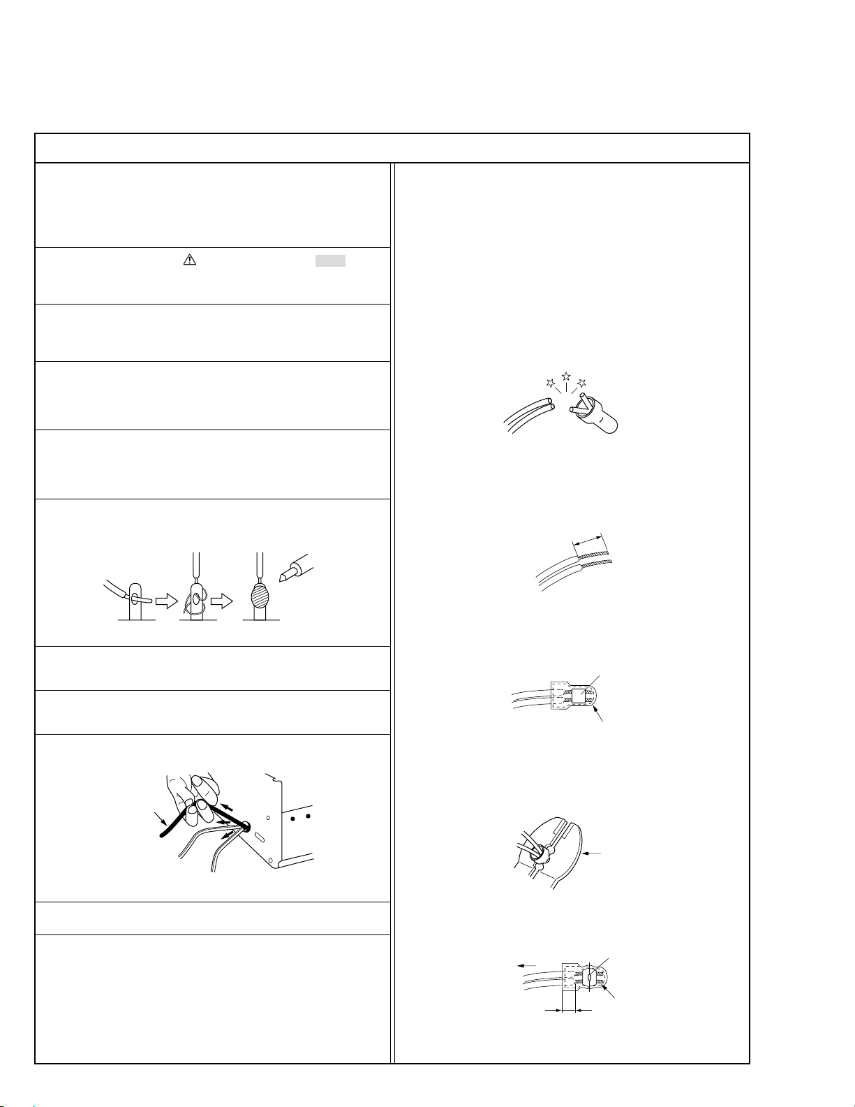
12. Crimp type wire connector
In such cases as when replacing the power transformer in sets
where the connections between the power cord and power
transformer primary lead wires are performed using crimp type
connectors, if replacing the connectors is unavoidable, in order to prevent safety hazards, perform carefully and precisely
according to the following steps.
1) Connector part number : E03830-001
2) Required tool : Connector crimping tool of the proper type
which will not damage insulated parts.
3) Replacement procedure
(1) Remove the old connector by cutting the wires at a point
close to the connector.
Important : Do not reuse a connector (discard it).
cut close to connector
Fig.3
(2) Strip about 15 mm of the insulation from the ends of
the wires. If the wires are stranded, twist the strands to
avoid frayed conductors.
15 mm
Fig.1
7. Observe that wires do not contact heat producing parts
(heatsinks, oxide metal film resistors, fusible resistors, etc.)
8. Check that replaced wires do not contact sharp edged or
pointed parts.
9. When a power cord has been replaced, check that 10-15 kg of
force in any direction will not loosen it.
Power cord
Fig.2
10. Also check areas surrounding repaired locations.
11. Products using cathode ray tubes (CRTs)
In regard to such products, the cathode ray tubes themselves,
the high voltage circuits, and related circuits are specified for
compliance with recognized codes pertaining to X-ray emission.
Consequently, when servicing these products, replace the cathode ray tubes and other parts with only the specified parts.
Under no circumstances attempt to modify these circuits.
Unauthorized modification can increase the high voltage value
and cause X-ray emission from the cathode ray tube.
Fig.4
(3) Align the lengths of the wires to be connected. Insert
the wires fully into the connector.
Metal sleeve
Connector
Fig.5
(4) As shown in Fig.6, use the crimping tool to crimp the
metal sleeve at the center position. Be sure to crimp fully
to the complete closure of the tool.
1.25
2.0
5.5
Fig.6
(5) Check the four points noted in Fig.7.
Not easily pulled free
Wire insulation recessed
more than 4 mm
Fig.7
Crimping tool
Crimped at approx. center
of metal sleeve
Conductors extended
1
p
Safety Check after Servicing
Examine the area surrounding the repaired location for damage or deterioration. Observe that screws, parts and wires have been
returned to original positions, Afterwards, perform the following tests and confirm the specified values in order to verify compliance with safety standards.
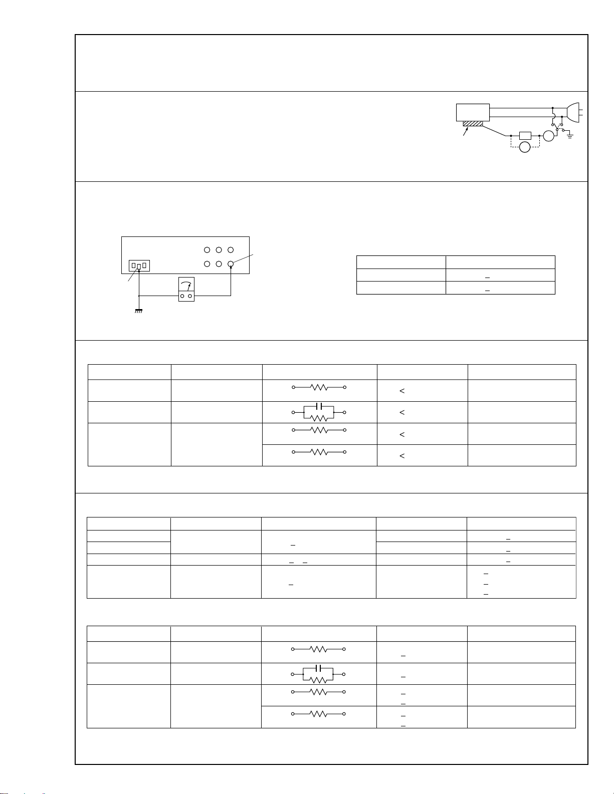
1. Leakage current test
Confirm specified or lower leakage current between earth ground/power cord plug prongs
and externally exposed accessible parts (RF terminals, antenna terminals, video and audio
input and output terminals, microphone jacks, earphone jacks, etc.).
Measuring Method : (Power ON)
Insert load Z between earth ground/power cord plug prongs and externally exposed accessible parts. Use an AC voltmeter to measure across both terminals of load Z. See figure 9 and
following table 2.
2. Grounding (Class 1 model only)
Confirm specified or lower grounding impedance between earth pin and externally exposed accessible parts (Video in, Video out,
Audio in, Audio out or Fixing screw etc.).
Measuring Method:
Connect milli ohm meter between earth pin and exposed accessible parts. See figure 10 and grounding specifications.
Externally
exposed
accessible
Z
V
art
Fig. 8
ab
c
A
Earth pin
Earth
<
MEDICAL USE
AC Line Voltage
100 V
110 to 130 V
110 to 130 V
220 to 240 V
<
GENERAL USE
AC Line Voltage
100 V
100 to 240 V
110 to 130 V
110 to 130 V
200 to 240 V
Exposed accessible part
Milli ohm meter
Fig. 9
>
Region Load Z
Japan
USA & Canada
Europe & Australia
Table 1 Leakage current specifications for each region
0.15 µF
>
Region
Japan
USA & Canada
Europe & Australia R 10 MØ/500 V DC
Insulation Resistance (R)
≤
R 1 MØ/500 V DC
≥≥
1 MØ R 12 MØ/500 V DC
≤
Table 2 Specifications for each region
1 kØ
2 kØ
50 kØ
Grounding Specifications
Region
USA & Canada
Europe & Australia
i 0.1 mA
1.5 kØ
i 0.1 mA
i 0.1 mA
i 0.1 mA
Dielectric Strength
AC 1 kV 1 minute
AC 1.5 kV 1 miute
AC 1 kV 1 minute
AC 3 kV 1 minute
AC 1.5 kV 1 minute
Grounding Impedance (Z)
≤
Z 0.2 ohm
≤
Z 0.2 ohm
Exposed accessible parts
Exposed accessible parts
Antenna earth terminals
Other terminals
Clearance Distance (d), (d')
d, d' 3 mm
d, d' 4 mm
d, d' 3.2 mm
≤
(Class 2)
(Class 1)
d 4 mm
≤
d' 8 mm (Power cord)
≤
d' 6 mm (Primary wire)
a, b, cLeakage Current ( i )
≤
≤
≤
Region
100 V
110 to 130 V
110 to 130 V
220 to 240 V
Note: These tables are unofficial and for reference only. Be sure to confirm the precise values for your particular country and locality.
Japan
USA & Canada
Europe & Australia
Table 3 Leakage current specifications for each region
0.15 µF
Load Z
1 kØ
2 kØ
50 kØ
1.5 kØ
≤
i 1 mA rms Exposed accessible parts
≤
i 0.5 mA rms
≤
i 0.7 mA peak
≤
i 2 mA dc
≤
i 0.7 mA peak
≤
i 2 mA dc
Exposed accessible parts
Antenna earth terminals
Other terminals
a, b, cLeakage Current ( i )AC Line Voltage
2
SECTION 1
PRECAUTIONS ON SERVICING
1.1 BEFORE DISASSEMBLING AND REASSEMBLING
1.1.1 Precautions
1. When disconnecting and reconnecting connectors, pay
careful attention to their wirings not to damage them,
particularly to the wiring of the CCU’s camera connector
that requires the most meticulous care for disconnection
and connection.
2. When unsoldering chip parts (IC in particular) for
replacement, completely remove solder particles from
them and their surroundings beforehand. Moreover, pay
heed to the circuit pattern not to exfoliate it from the
substrate during replacement of a chip part.
3. Don’t use any chip part that was once removed.
4. Handle the optical block assembly with meticulous care.
Don’t apply it a strong shock.
5. There is a lithium battery for backing up the timer on the
POWER board assembly. Pay careful attention to the
lithium battery for accident prevention.
1.1.2 Disassembly of optical block assembly
Since the CCD is precisely glued to the prism in the optical
block assembly, the CCD cannot be replaced individually if
it comes into failure. Therefore, the optical block assembly is
subject to repair by the JVC Video Division. If there is
something wrong in the optical block assembly, send the
camera head assembly whole with a written request filled out
with necessary matters to the Service Engineering Section,
Video Products Division, JVC.
1. Tools and test instruments necessary for check and
adjustment
1) Multiscan monitor or HD color monitor
2) 1/2” professional zoom lens (Model No. YH13x7.5B12
or YH13x7.5K12 is recommended by the Professional
Video Division)
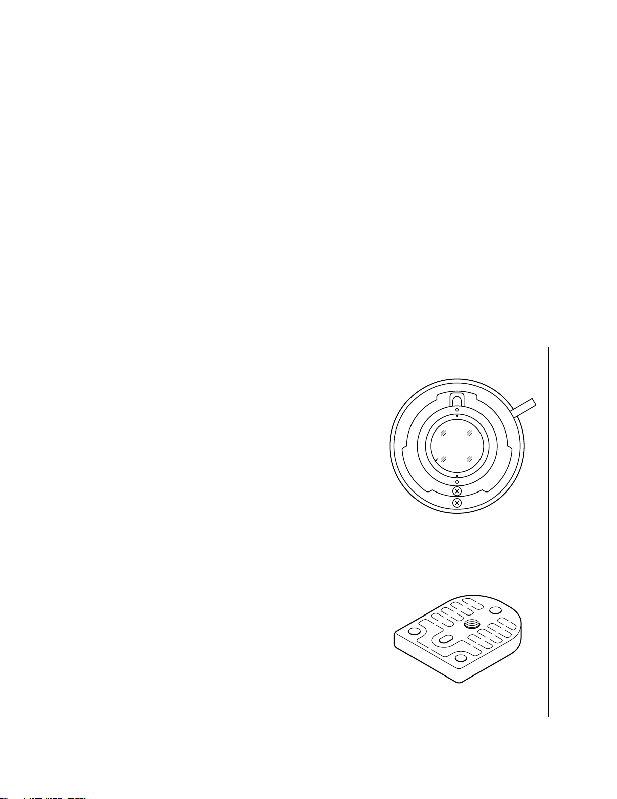
3) 1/2” bayonet mount adapter (Model No. GL-V62)
4) Tripod
5) Tripod attachment (Part No. SC31968)
6) Tripod attachment fitting screw (Part No. SPSP2612Z)
7) Resolution chart for HDTV
8) Gray scale chart (for NTSC, Part No. GS-2A)
9) AC power adapter (Model No. AA-P200)
10) NTSC signal generator
11) Oscilloscope (for 300 MHz or more)
12) Wrench for removing connector ring
13) Illuminometer
14) Color temperature meter
15) Camera cable (standard accessory)
16) Digital voltmeter
17) Lighting apparatus (3200 K halogen lamp)
1/2” bayonet mount adapter (GL-V62)
1.2 PREPARATION AND PRELIMINARY CHECK REQUIRED FOR ADJUSTMENT
1.2.1 Before adjustment
1. Use two or more lighting apparatuses whose color tem-
perature is 3200 K for illuminating the test pattern, and
uniformly light up the test pattern surface with illuminance
of 2000 lx approximately while checking it with an
illuminometer. If the pattern surface is unevenly illuminated, adjustment may result in failure. Carefully set up
lighting apparatuses so that the test pattern is illuminated
uniformly. (It is desired to use two or more light sources.)
2. Be sure to use a clean test pattern as far as circum-
stances permit.
1.2.2 Tools and jigs required for repair and adjustment
Use the following tools, jigs and test instruments to perform
check and adjustment properly.
Tripod attachment (SC31968)
1-1
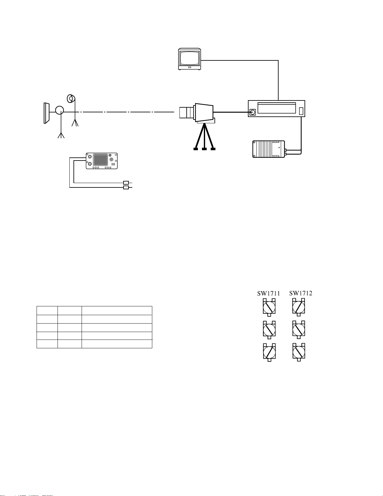
2. Standard setup
Test pattern
Lighting of 3200 K
Oscilloscope
Multiscan monitor
VIDEO
OUTPUT
AC power adapter
3. Complementary explanation of functions of internal
switches of boards (CCU section)
SW1701: DSP (IC1701, IC1707) reset switch (toggle switch)
SW1704: Switch to operate DSP2 directly
1: Direct operation mode ON/OFF switch
2: TEST signal generation ON/OFF switch
3,4: TEST signal selector switch
3 4 TEST signal waveform
OFF OFF Color bar
OFF OFF 100% white window
OFF ON Blue back
OFF ON Cross pattern
Turn on SW1704-1 to generate the TEST signal.
Note:
SW1710: Switch to output a camera picture forcedly
replacing characters in the upper part of the
screen
SW1711: TEST signal generation ON/OFF switch
SW1712: TEST signal generation ON/OFF switch
100% white window
Vertical ramp
Horizontal ramp
1-2

Warnings for accident prevention in handling battery
WARNING: Fire, Explosion, Leakage and Burn Hazard. Do not recharge, Disassemble, Heat Above
212°F, Incinerate, Or Expose Contents To Water. Be Sure The Battery Is Inserted In The Right Direction.
The lithium battery incorporates inflammable substances such as lithium and organic solvent, etc.
inside.
If the lithium battery is handled in a wrong way, it may cause injury, fire and other dangerous
accident caused by heating, bursting, firing, etc. Be sure to follow the instructions mentioned below
to prevent you from an unexpected accident before unpacking, in and after using the battery.
1. Be careful of short-circuit.
If the positive (+) and negative (-) terminals come into contact with each other or with other metallic
material, the battery is shortcircuited. If many batteries are left disorderly and their terminals are in contact
with others, some of the batteries may generate heat, burst or fire and resultingly cause accident.
2. Neither immerse battery in water nor throw it into fire.
If the lithium battery is immersed in water or thrown into fire, it may fire or burst violently.
3. Avoid heating the battery.
If the lithium battery is heated at a temperature of 100°C or more, the electrolyte may leak from the battery
because the plastic materials such as gasket and separator are damaged or the battery may burst or fire
because the battery is heated by internal shortcircuit.
4. Avoid directly soldering the battery.
If the lithium battery is directly soldered, the electrolyte may leak from it because the plastic materials such
as the gasket and separator are damaged or the battery may burst or fire because it is heated by internal
shortcircuit.
5. Avoid charging the battery.
If the primary battery is charged, the battery may generate gas inside and it may resultingly cause
expansion, burst or fire of the battery.
6. Avoid dismantling the battery.
If the lithium battery is dismantled, some kind of gas is generated and it stimulates the throat or the
dismantled battery may fire because the negative lithium reacts on water and generates heat.
7. Avoid deformation with pressure.
If the lithium battery is deformed with pressure, the electrolyte may leak from it because of warp or
damage in the sealing, or the battery may burst or fire because it is heated by internal shortcircuit.
8. Don’t use batteries of different types or old ones mixedly.
If batteries of different brands/types are mixedly used or new and old batteries are mixedly used, it may
cause expansion, burst or fire of the batteries because they are over-discharged by difference in their
characteristics of voltage, capacitance, etc.
9. Avoid setting of the battery in wrong polarities.
If the battery is set in wrong polarities (+ and - poles are set reversely), the battery may be shortcircuited
and it may resultingly cause heating, bursting or firing in the battery.
1-3
SECTION 2
ELECTRICAL ADJUSTMENT
2.1 ADJUSTMENT OF CAMERA
2.1.1 Initial setting
1. Standard shooting conditions
1) Ambient temperature: +20° to +25°C
2) Standard lighting: 3200 K, 2000 lx (When the illuminance is 4000 lx, stop down the lens aperture by 1 stop.)
3) Lens: YH13x7.5B12 or YH13x7.5K12
4) GAIN: NORMAL
5) Shutter: OFF
6) Aperture: F5.6 (F8 when illuminance is 4000 lx)
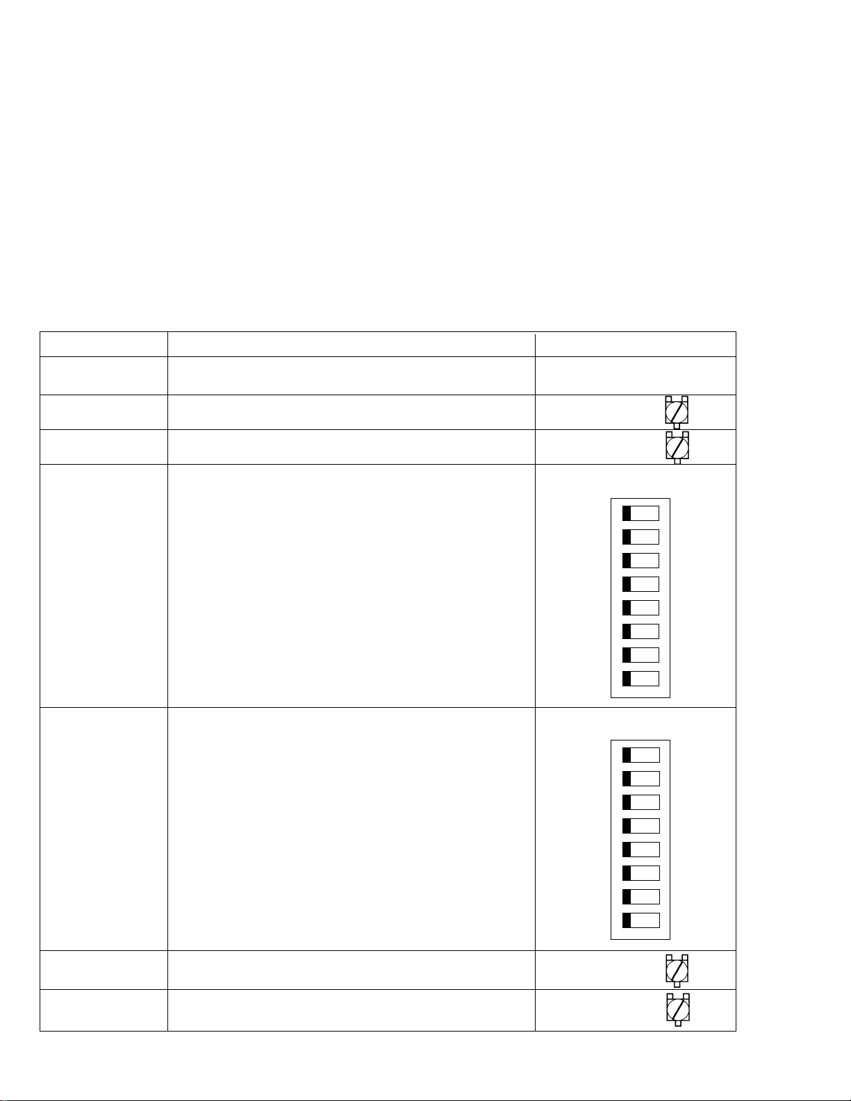
2. Functions and initial settings of internal switches of boards (CCU section)
Switch Function Initial setting
SW1701 DSP (IC1701, 1707) reset switch (Toggle SW)
SW1702 Direct GAMMA ON/OFF ON(GND)
SW1703 Direct OB clamp control signal ON/OFF ON
SW1704 Octuplet DIP switch for DSP2 (IC1707) (All OFF) OFF (GND) ON
1
2
3
4
5
6
7
8
SW1705 Octuplet DIP switch for SVP (IC1718, 1719) (All OFF) OFF (GND) ON
1
2
3
4
5
6
SW1710 Character display in the upper part ON
SW1711, 1712 TEST signal setting switch ON
Table 2-1-1
2-1
7
8
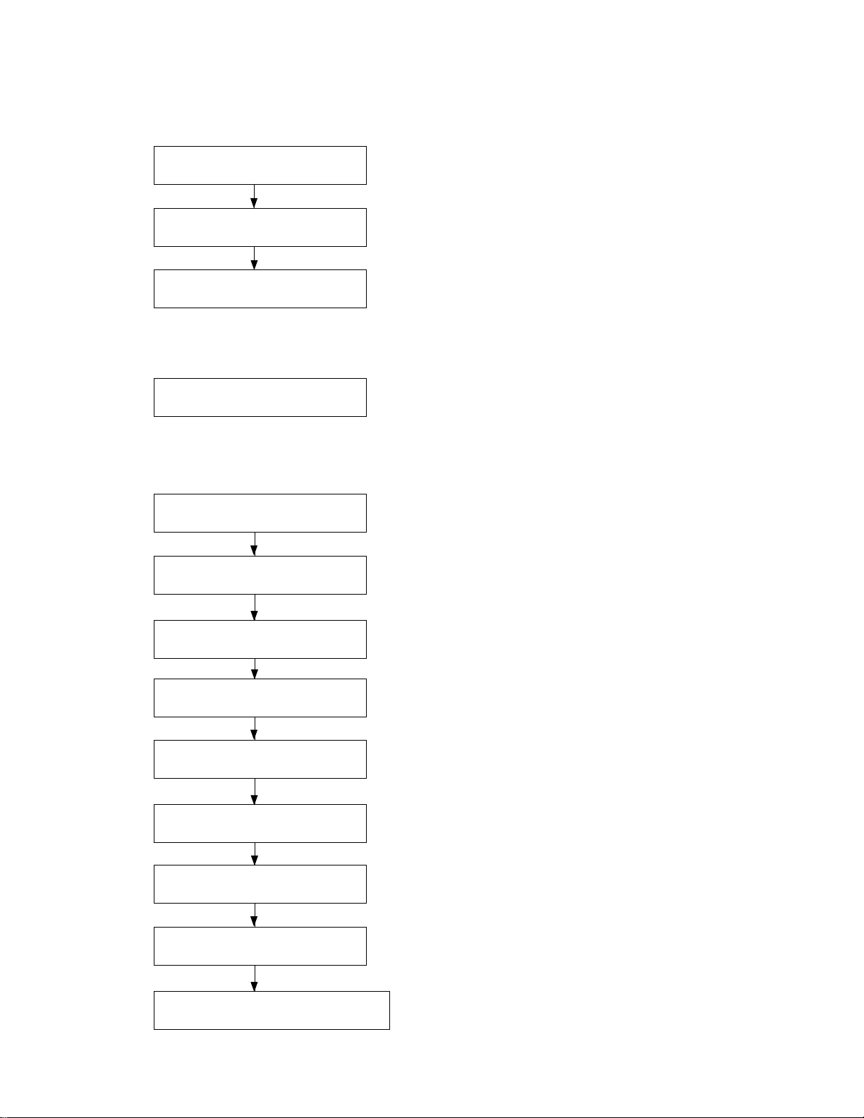
2.1.2 Adjustment procedure
1. Standard adjustment procedure
2.1.1 (1 - 2)
Initial setting
2.1.3 (1 - 3)
Adjustment of camera head
2.1.4 (1 - 23)
Adjustment of CCU section
2. Adjustment procedure at installation (On attaching lens to camera)
2.1.4 (24)
Dynamic shading adjustment
3. Adjustment procedure at camera head replacement
2.1.1 (1 - 2)
Initial setting
2.1.3 (1 - 3)*1
Camera head adjustment
2.1.4 (1)
Initial setting of CCU section
2.1.4 (3)
Input gain adjustment
2.1.4 (4)
Knee level adjustment
2.1.4 (5)
Clock phase adjustment
2.1.4 (16)
R gain for tint adjustment
*1: When the camera head has individually been
adjusted, this adjustment is unnecessary.
2.1.4 (17)
B gain for tint adjustment
2.1.4 (20)
G1 and G2 balance (fine adjustment)
2-2
 Loading...