

Page 1
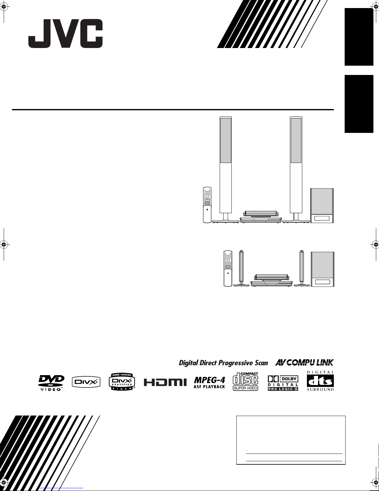
NETWORK MEDIA SYSTEM
SYSTÈME MÉDIA RÉSEAU
DD-8
Consists of CA-DD8, SP-PWDD8,
SP-DD8F and SP-DD8S
Se compose de CA-DD8, SP-PWDD8,
SP-DD8F et SP-DD8S
EnglishFrançais
DD-3
Consists of CA-DD3, SP-PWDD3,
SP-DD3F and SP-DD8S
Se compose de CA-DD3, SP-PWDD3,
SP-DD3F et SP-DD8S
INSTRUCTIONS
MANUEL D’INSTRUCTIONS
For Customer Use:
Enter below the Model No. and Serial
No. which are located either on the rear,
bottom or side of the cabinet. Retain this
information for future reference.
Model No.
Serial No.
LVT1546-001A
[J]
Page 2

Warnings, cautions and others/
Mises en garde, précautions et indications diverses
(For U.S.A.)
(For U.S.A.)
(For U.S.A.)
INFORMATION
This equipment has been tested and found to comply with the limits for a Class B digital device, pursuant
to part 15 of the FCC Rules. These limits are designed to provide reasonable protection against harmful
interference in a residential installation.
This equipment generates, uses and can radiate radio frequency energy and, if not installed and used in
accordance with the instructions, may cause harmful interference to radio communications. However,
there is no guarantee that interference will not occur in a particular installation. If this equipment does
cause harmful interference to radio or television reception, which can be determined by turning the equipment off and on, the user is encouraged to try to correct the interference by one or more of the following
measures:
Reorient or relocate the receiving antenna.
Increase the separation between the equipment and receiver.
Connect the equipment into an outlet on a circuit different from that to which the receiver is connected.
Consult the dealer or an experienced radio/TV technician for help.
CAUTION
Changes or modifications not approved by JVC could void the user’s authority to operate the equipment.
For Canada/pour le Canada
THIS DIGITAL APPARATUS DOES NOT EXCEED THE CLASS B LIMITS FOR RADIO NOISE EMISSIONS FROM DIGITAL APPARATUS AS SET OUT IN THE INTERFERENCE-CAUSING EQUIPMENT
STANDARD ENTITLED “DIGITAL APPARATUS”, ICES-003 OF THE DEPARTMENT OF COMMUNICATIONS.
CET APPAREIL NUMERIQUE RESPECTE LES LIMITES DE BRUITS RADIOELECTRIQUES APPLICABLES AUX APPAREILS NUMIRIQUES DE CLASSE B PRESCRITES DANS LA NORME SUR LE MATERIEL BROUILLEUR: “APPAREILS NUMERIQUES”, NMB-003 EDICTEE PAR LE MINISTRE DES
COMMUNICATIONS.
G-1
Page 3
CAUTION
To reduce the risk of electrical shocks, fire, etc.:
1. Do not remove screws, covers or cabinet.
2. Do not expose this appliance to rain or moisture.
ATTENTION
Afin d’éviter tout risque d’électrocution, d’incendie, etc.:
1. Ne pas enlever les vis ni les panneaux et ne pas ouvrir le coffret de l’appareil.
2. Ne pas exposer l’appareil à la pluie ni à l’humidité.
CAUTION
• Do not block the ventilation openings or holes.
(If the ventilation openings or holes are blocked by a newspaper or cloth, etc., the heat may not be able
to get out.)
• Do not place any naked flame sources, such as lighted candles, on the apparatus.
• When discarding batteries, environmental problems must be considered and local rules or laws governing the disposal of these batteries must be followed strictly.
• Do not expose this apparatus to rain, moisture, dripping or splashing and that no objects filled with liquids, such as vases, shall be placed on the apparatus.
ATTENTION
• Ne bloquez pas les orifices ou les trous de ventilation.
(Si les orifices ou les trous de ventilation sont bloqués par un journal un tissu, etc., la chaleur peut ne
pas être évacuée correctement de l’appareil.)
• Ne placez aucune source de flamme nue, telle qu’une bougie, sur l’appareil.
• Lors de la mise au rebut des piles, veuillez prendre en considération les problèmes de l’environnement
et suivre strictement les règles et les lois locales sur la mise au rebut des piles.
• N’exposez pas cet appareil à la pluie, à l’humidité, à un égouttement ou à des éclaboussures et ne
placez pas des objets remplis de liquide, tels qu’un vase, sur l’appareil.
IMPORTANT FOR LASER PRODUCTS
1. CLASS 1 LASER PRODUCT
2. CAUTION: Do not open the top cover. There are no user serviceable parts inside the unit; leave all
servicing to qualified service personnel.
3. CAUTION: Visible and/or invisible class 1M laser radiation when open. Do not view directly with
optical instruments.
4. REPRODUCTION OF LABEL: CAUTION LABEL, PLACED INSIDE THE UNIT.
IMPORTANT POUR PRODUITS LASER
1. PRODUIT LASER CLASSE 1
2. ATTENTION: N’ouvrez pas le couvercle supérieur. Il n’y a aucune pièce réparable par l’utilisateur à
l’intérieur de l’appareil; confiez toute réparation à un personnel qualifié.
3. ATTENTION: Rayonnement laser visible et/ou invisible de classe 1M une fois ouvert. Ne pas regarder
directement dans le faisceau avec des instruments optiques.
4. REPRODUCTION DE L’ÉTIQUETTE: ÉTIQUETTE DE PRÉCAUTION PLACÉE À L’INTERIEUR DE
L’APPAREIL.
G-2
Page 4
Warnings, cautions and others (continued)/
Mises en garde, précautions et indications diverses (suite)
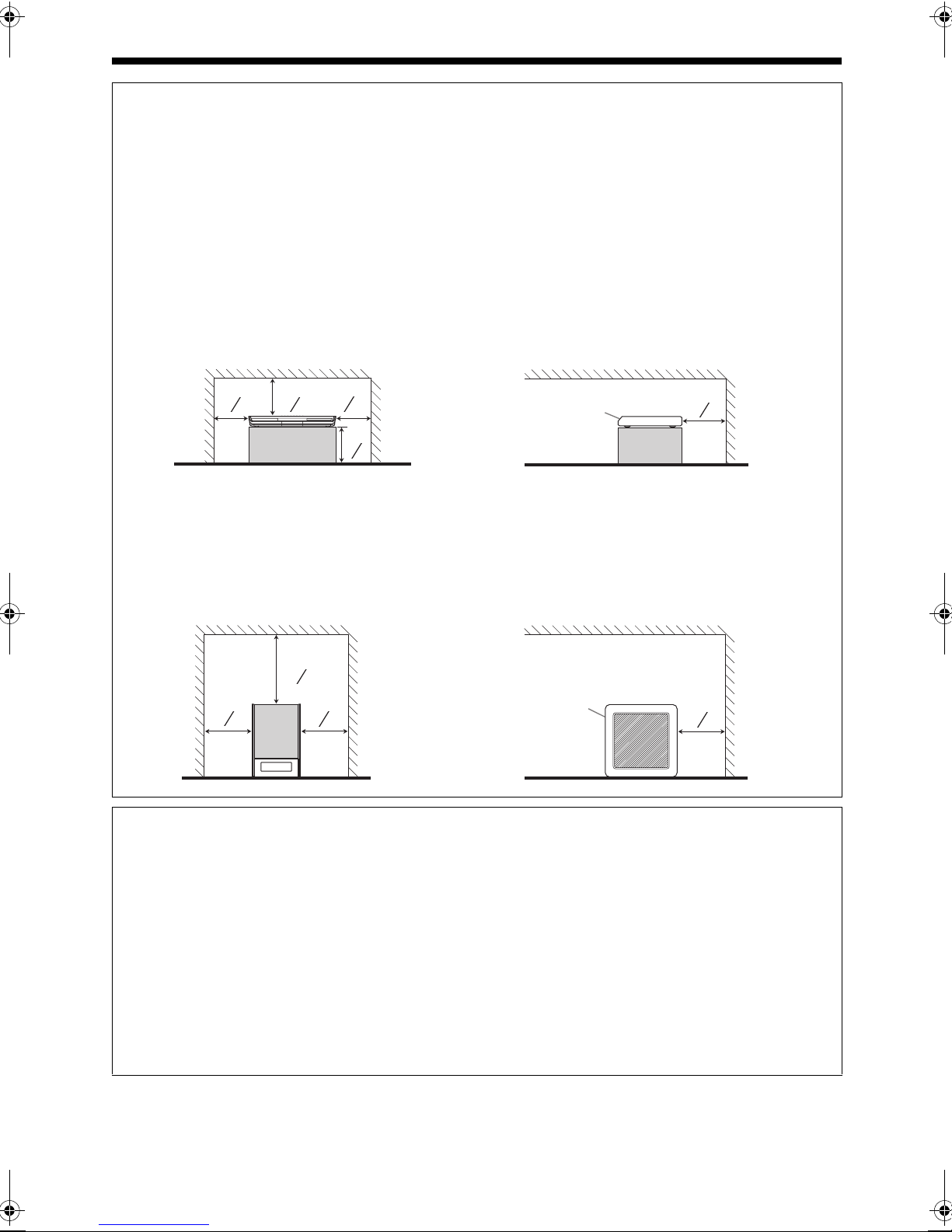
CAUTION: Proper Ventilation
To avoid risk of electric shock and fire and to protect from damage, place the apparatus on a level surface. The minimal clearances are shown below:
MISE EN GARDE: Ventilation correcte
Pour éviter les risques d’électrochoc ou d’incendie, et de manière à éviter les dommages, placer l’appareil sur une surface en hauteur. L’espace minimal est indiqué ci-dessous:
Main unit (CA-DD8/CA-DD3)
Unité principale (CA-DD8/CA-DD3)
Front view Side view
Façade Vue latérale
Wall or obstructions
Mur ou encombrement
3 cm
3
(1 ″)
16
8 cm
(3 ″)
3 cm
3
3
(1 ″)
16
16
15cm
15
(5 ″)
No obstructions
16
Pas d’encombrement
Wall or obstructions
Mur ou encombrement
Front
Façade
Subwoofer (SP-PWDD8/SP-PWDD3)
Caisson de grave (SP-PWDD8/SP-PWDD3)
Front view Side view
Façade Vue latérale
Wall or obstructions
Mur ou encombrement
20 cm
7
(7 ″)
8
15 cm
15
(5 ″)
16
15 cm
15
(5 ″)
16
Wall or obstructions
Mur ou encombrement
Front
Façade
No obstructions
Pas d’encombrement
10 cm
15
(3 ″)
16
15 cm
15
(5 ″)
16
CAUTION — F button! (CA-DD8/CA-DD3)
Disconnect the mains plug to shut the power off completely (the STANDBY lamp goes off). When installing
the apparatus, ensure that the plug is easily accessible.
The F button in any position does not disconnect the mains line.
• When the system is on standby, the STANDBY lamp lights red.
• When the system is turned on, the STANDBY lamp goes off.
The power can be remote controlled.
ATTENTION — Touche F ! (CA-DD8/CA-DD3)
Déconnectez la fiche secteur pour mettre l’appareil complètement hors tension (le témoin STANDBY l
s’éteint). Lors de l’installation de l’appareil, assurez-vous que la fiche soit facilement accessilble.
La touche F, dans n’importe quelle position, ne déconnecte pas le système du secteur.
• Quand le système est en attente, le témoin STANDBY est allumé en rouge.
• Quand le système est sous tension, le témoin STANDBY s’éteint.
L’alimentation peut être télécommandée.
G-3
Page 5
CAUTION (SP-PWDD8/SP-PWDD3)
The power supply to the subwoofer is linked to the center unit.
Disconnect the mains plug to shut the power off completely (the POWER ON lamp goes off).
When installing the apparatus, ensure that the plug is easily accessible.
• When the system is turned on, the POWER ON lamp lights green.
ATTENTION (SP-PWDD8/SP-PWDD3)
L’alimentation du caisson de grave est reliée à l’unité centrale.
Déconnectez la fiche secteur pour mettre l’appareil complètement hors tension (le témoin POWER ON l
s’éteint). Lors de l’installation de l’appareil, assurez-vous que la fiche soit facilement accessible.
• Quand l’appareil est sous tension, le témoin POWER ON est allumé en vert.
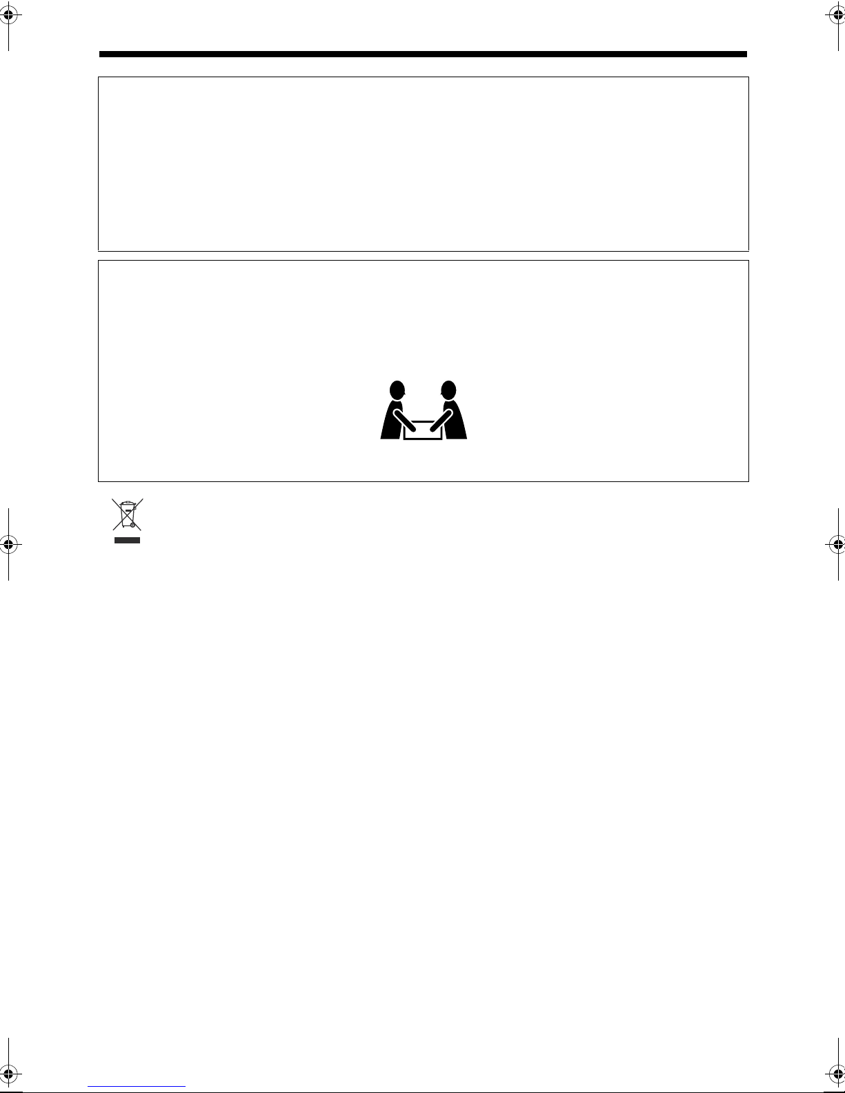
CAUTION
To avoid personal injury or accidentally dropping the unit, have two persons unpack, carry, and install the
unit.
ATTENTION
Pour éviter toute blessure personnelle ou toute chute accidentelle de l’appareil, celui-ci doit être déballé,
transporté et installé par deux personnes.
DD-8: 48.5 kg (106.9 lbs)
DD-3: 22.7 kg (51 lbs)
[European Union only]
[Union européenne seulement]
G-4
Page 6

Table of contents
Thank you for purchasing a JVC product.
Please read all instructions carefully before operation, to ensure your complete understanding and to obtain
English
the best possible performance from the unit.
Pausing playback..........................................27
Introduction
Part description .............................3
Using the remote control ..............4
Introduction
Preparation
Preparation.....................................5
Connecting the antennas ................................5
Connecting the speakers ................................6
Connecting a TV ...........................................11
Connecting a portable digital audio player.... 14
Connecting other digital audio devices .........15
Connecting other analog audio devices........ 15
Connecting the power cable .........................15
Advancing the picture frame by frame ..........27
Fast reverse/fast forward search ..................28
Playing back from a position 10 seconds
before..........................................................28
Slow motion playback ...................................28
Skipping to the beginning of a
chapter/track/file .........................................28
Selecting a chapter/track using the number
buttons........................................................29
Skipping at approximately 5 minute
intervals ......................................................29
Selecting a track from the menu screen .......29
Convenient functions of disc/
file playback
Basic operations
Basic operations..........................16
Using the number buttons.............................16
Turning on the main unit ...............................16
Adjusting the volume.....................................16
Turning off the sound temporarily ................. 16
Sharpening the voice sound .........................17
Adjusting the bass/treble sound.................... 17
Adjusting the volume of the
center surround speaker/subwoofer ........... 17
Adjusting the volume balance between
the left and right speakers ..........................17
Changing the brightness of the display
window........................................................18
Using the sleep timer ....................................18
Auto standby function ...................................19
Locking disc ejection.....................................19
Listening to radio broadcasts
Listening to radio broadcasts ....20
Selecting a radio station................................20
Tuning in to a preset radio station.................21
Basic operations of disc/file
playback
Convenient functions of disc/file
playback .......................................30
Selecting the audio language, subtitle
language and view angle............................30
Playing back a disc/file in the desired order
(Program playback) ....................................31
Playing back a disc/file in a random order
(Random playback).....................................32
Magnifying the picture...................................32
Playing back a disc/file repeatedly
(Repeat playback).......................................33
Selecting the surround mode ........................33
Adjusting the picture quality (VFP)................34
Using the status bar and the
menu bar.......................................35
Playing back a specified part repeatedly
(A-B repeat playback).................................36
Designating the time
(Time search)..............................................36
Changing the initial settings with
the preference screen .................37
Basic operations ...........................................37
LANGUAGE..................................................37
PICTURE ...................................................... 38
AUDIO...........................................................39
OTHERS....................................................... 39
Language codes ..........................40
Basic operations of disc/file
playback .......................................22
Playing back a disc .......................................22
Playing back a file.........................................23
Display window on the main unit for
disc/file types ..............................................24
Stopping playback.........................................27
Resuming playback.......................................27
1
Page 7
Playing back sources from
other devices
Playing back sources from other
devices..........................................41
Selecting other devices as the source ..........41
Selecting the signal gain...............................41
QP LINK........................................................42
Operating other devices
using the remote control
Operating other devices using
the remote control .......................43
Operating a TV using the remote control ......43
Operating a VCR/DBS using the
remote control.............................................44
Reference
Using the AV COMPU LINK
function.........................................46
Preparation for the AV COMPU LINK
function .......................................................46
Operating the AV COMPU LINK function .....46
Notes on operation ......................47
Suitable locations for the main unit ............... 47
Condensation................................................47
Cleaning the main unit ..................................47
License and trademark .................................47
Notes on handling .........................................48
Notes on discs/files .....................49
Playable disc/file types..................................49
Data hierarchy...............................................52
Handling discs............................................... 52
Troubleshooting .......................... 53
Specifications ..............................54
Main unit (CA-DD8/CA-DD3) ........................54
Subwoofer for DD-8 (SP-PWDD8)................ 54
Subwoofer for DD-3 (SP-PWDD3)................ 55
Left and right speakers for DD-8
(SP-DD8F).................................................. 55
Left and right speakers for DD-3
(SP-DD3F).................................................. 55
Center surround speaker (SP-DD8S) ........... 56
Supplied accessories ....................................56
English
Introduction
How to read this manual
• This manual explains operations assuming
that you will use the remote control. Some
buttons on the main unit are the same as
those on the remote control. You can use
either button in this case.
• Some diagrams in this manual are simplified
or exaggerated for the purpose of explanation.
• You can operate some functions differently
from the explanation given in this manual.
• Depending on the disc/file, you may not
obtain the explained result even after following the operation in this manual.
• The following marks refer to the usable
discs/files for the explained function.
2
Page 8
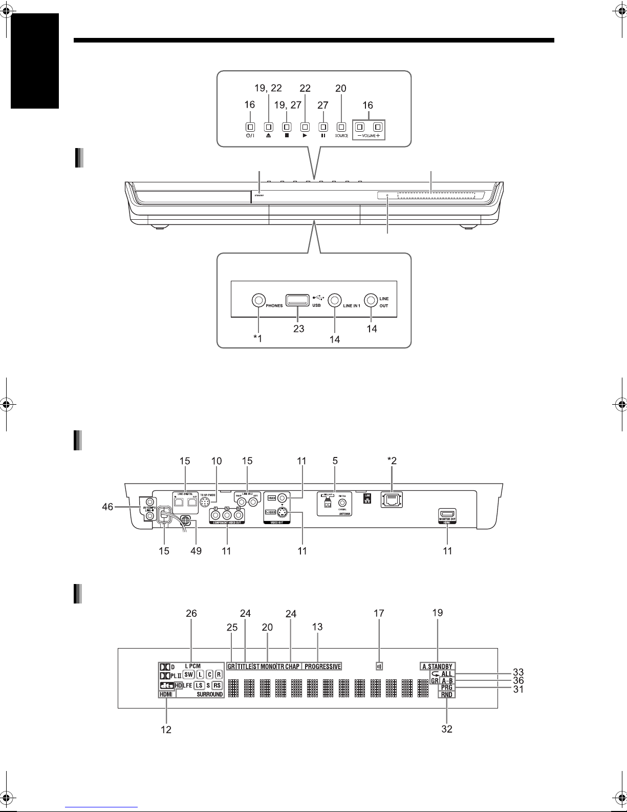
Part description
The numbers refer to the pages in which the parts are explained.
English
Front view
Introduction
STANDBY lamp
These terminals are available when
the front cover is open.
Refer to “Display window” shown below.
Remote control sensor
*1 The [PHONES] terminal is for connecting a pair of headphones equipped with a stereo plug (not supplied).
When the headphones are connected, the speakers do not produce any sound. (“HEADPHONE” appears
in the display window.)
During playback, when you connect or disconnect headphones, sound from the [LINE OUT] and [LINEDIGITAL OUT] terminals may be intermittent. While recording sound to another device, do not connect or
disconnect headphones.
Rear view
*2 Refer to the separate volume of the operation manual for the network function.
Display window
3
Page 9

Using the remote control
The numbers refer to the pages in which the parts
are explained.
Inserting the batteries into the
remote control
• If the effective range of the remote control
decreases, replace both batteries.
■ CAUTION
• Do not expose batteries to heat or flame.
Operating the system from the
remote control
English
Introduction
R6P (SUM-3)/AA (15F) type dry-cell
batteries (supplied)
* Refer to the separate volume of the operation
manual for the network function.
Point the remote control directly at the
front of the main unit.
• Do not block the remote control sensor on the
main unit.
• Use the remote control at a position higher than
the main unit.
4
Page 10
Preparation Do not turn on the power until you complete the connection.
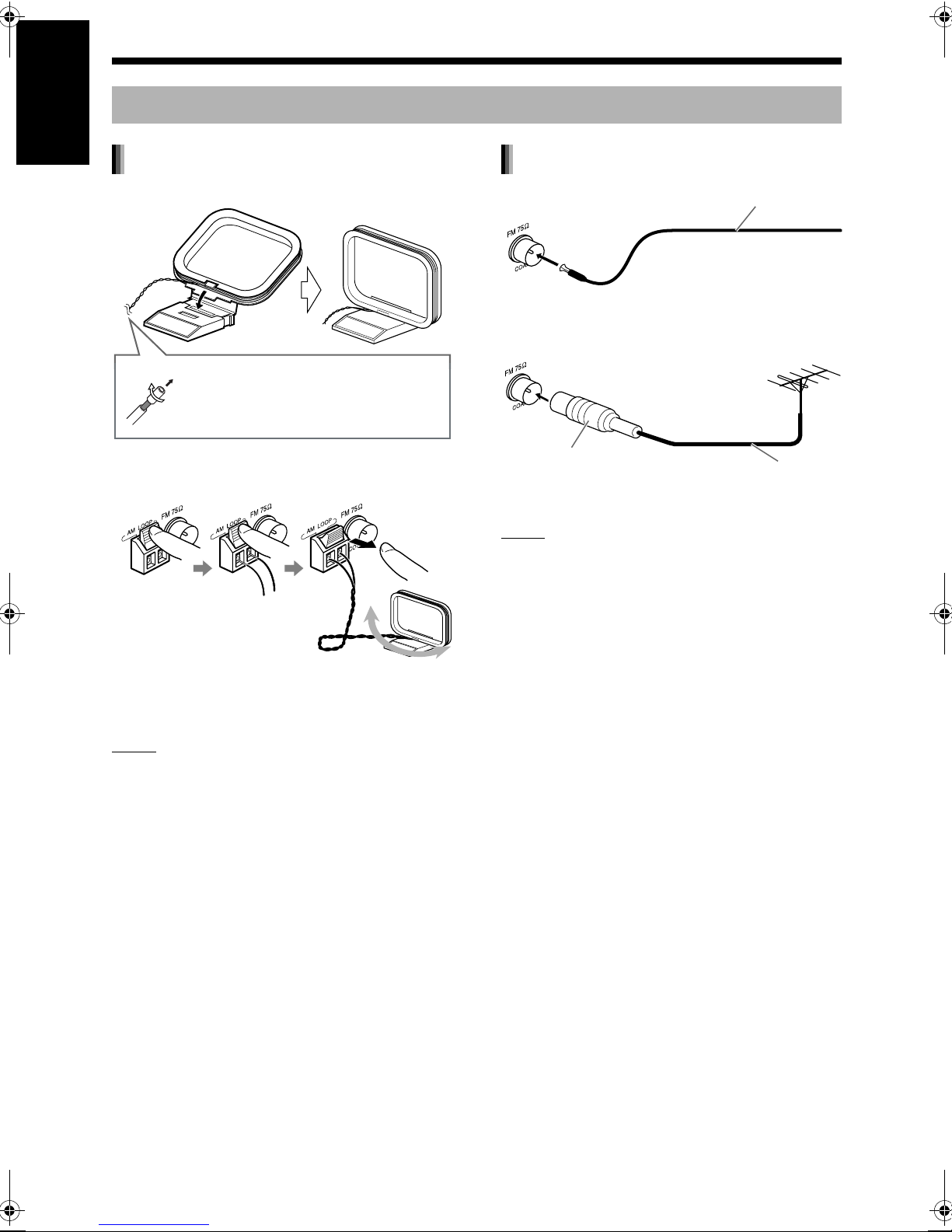
Connecting the antennas
English
AM loop antenna (supplied)
FM antenna (supplied)
Setting up the AM loop antenna
Preparation
If insulation covers the tips of the
antenna cable, twist and pull off
the insulation.
Connecting the AM loop antenna
Main unit (rear view)
Main unit (rear view)
Stretch out the FM
antenna horizontally.
If reception is poor
Main unit (rear view)
75Ω coaxial connector
(not supplied)
NOTE
• A coaxial cable is recommended as it reduces
interference for FM reception.
FM antenna
Outdoor FM antenna
cable (not supplied)
Turn the AM loop antenna to find the best position
for radio reception.
NOTE
• Make sure that the antenna conductors do not
touch any other terminals. This could cause poor
reception.
5
Page 11
Connecting the speakers
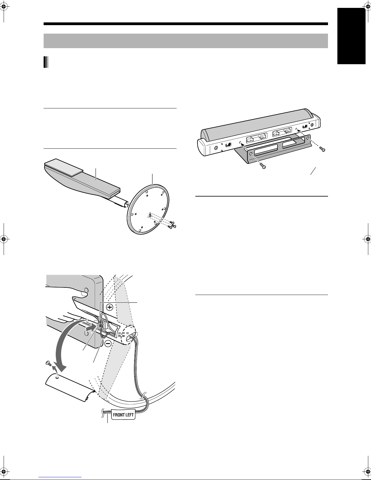
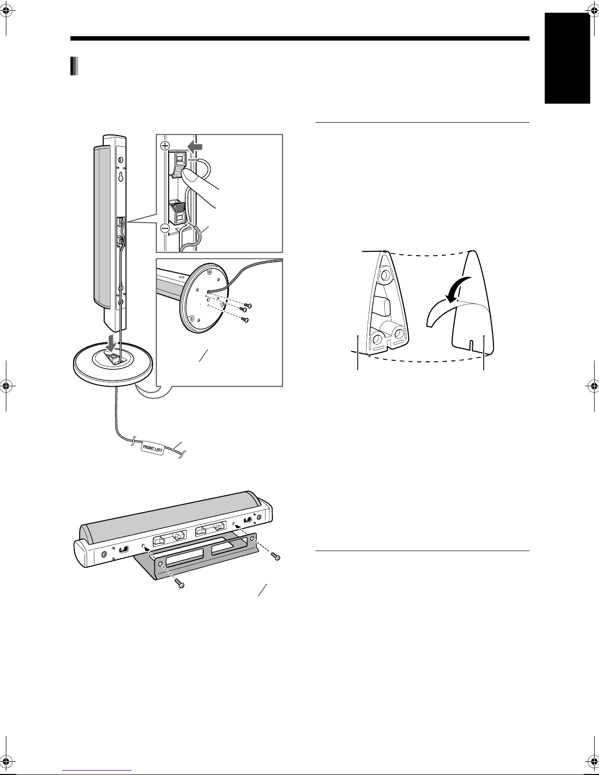
Assembling the speaker stands (DD-8)
The speakers for DD-8 must be assembled to the speaker stands before the speakers can be connected to
the subwoofer. Follow the diagrams below.
English
Left and right speakers
■ CAUTION
• The left and right speakers for DD-8 are considerably heavy. Care must be taken in carrying and
handling them. Injury to personnel or damage to
devices may result if the left/right speaker falls.
Speaker body
Speaker stand
Mount the speaker body perpendicular to the
speaker stand. Use the supplied M4 x 25-mm (1″)
screws (3) to fasten each speaker to its speaker
stand.
Center surround speaker
Use the supplied
M5 x 14-mm (″)
screws (2) to fasten
the speaker stand.
■ CAUTION
• The center surround speaker for DD-8 can be
installed on a wall.
• Be sure to have the speaker installed on the wall
by qualified personnel.
• DO NOT install the speaker on the wall by yourself to avoid unexpected damage from it falling
off the wall due to incorrect installation or weakness in wall structure.
• Care must be taken in selecting a location for
speaker installation on a wall. Injury to personnel
or damage to devices may result if the installed
speaker interferes with daily activities.
5
8
Preparation
Black
Black line
Left/right speaker cable (supplied)
Remove the screw and the terminal cover. After
connecting the speaker cables, reattach the terminal cover to the speaker body and tighten the screw.
Red
6
Page 12
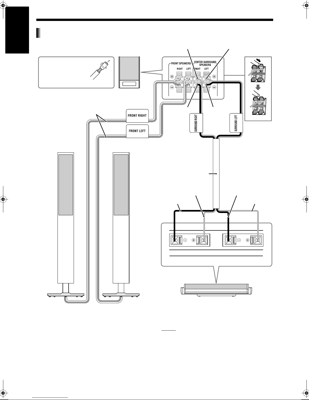
Preparation (continued) Do not turn on the power until you complete the connection.
Connecting the speakers to the subwoofer (DD-8)
English
Gray Blue
Rear view
Before connecting the
speaker cables, twist
and pull off the insulation at the end of each
Preparation
speaker cable.
Subwoofer
(SP-PWDD8)
Black lines
Black
Center surround
speaker cable
(supplied)
Gray
Black
Black
Black
Blue
Right speaker
(SP-DD8F)
The speakers are shown assembled to the speaker
stands on page 6.
The left and right speakers are the same.
7
Left speaker
(SP-DD8F)
LeftRight
Rear view
Center surround speaker (SP-DD8S)
The speaker is shown assembled to the speaker
stand on page 6.
NOTE
• When connecting the speaker cable to the terminal on the center surround speaker, make sure
that the end of speaker cable does not touch any
other nearby metallic parts.
Page 13
Assembling the speaker stands (DD-3)
The speakers for DD-3 must be assembled to the speaker stands before the speakers can be connected to
the subwoofer. Follow the diagrams below.
English
Left and right speakers
Use the supplied M4 x
16-mm ( ″) screws (3) to
fasten each speaker to its
speaker stand.
Black line
11
16
■ CAUTION
• The left and right speakers and center surround
speaker for DD-3 can be installed on a wall.
• Be sure to have the speakers installed on the
wall by qualified personnel. Bottom covers (2)
are supplied with DD-3 for installing the left and
right speakers on the wall.
Affixing the bottom covers to the left and
right speakers
Left/right speaker
(bottom view)
Bottom cover (for
wall installation)
Preparation
Left/right speaker cable
(supplied)
Center surround speaker
Use the supplied
M5 x 14-mm ( ″)
5
8
screws (2) to fasten
the speaker stand.
Peel off the sheet from the bottom cover, and
then affix the bottom cover to the left/right
speaker.
• DO NOT install the speakers on the wall by yourself to avoid unexpected damage from them falling off the wall due to incorrect installation or
weakness in wall structure.
• Care must be taken in selecting a location for
speaker installation on a wall. Injury to personnel
or damage to devices may result if the installed
speakers interfere with daily activities.
8
Page 14
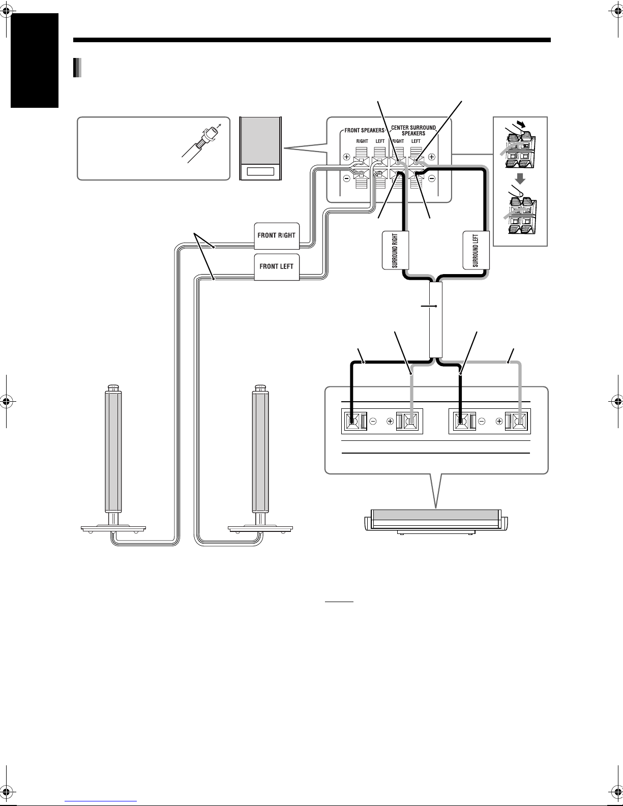
Preparation (continued) Do not turn on the power until you complete the connection.
Connecting the speakers to the subwoofer (DD-3)
English
Gray Blue
Rear view
Before connecting the
speaker cables, twist
and pull off the insulation at the end of each
Preparation
speaker cable.
Subwoofer
(SP-PWDD3)
Black lines
Black
Center surround
speaker cable (supplied)
Gray
Black
Rear view
Black
Black
Blue
LeftRight
Right speaker
(SP-DD3F)
The speakers are shown assembled to the speaker
stands on page 8.
The left and right speakers are the same.
9
Left speaker
(SP-DD3F)
Center surround speaker (SP-DD8S)
The speaker is shown assembled to the speaker
stand on page 8.
NOTE
• When connecting the speaker cable to the terminal on the center surround speaker, make sure
that the end of speaker cable does not touch any
other nearby metallic parts.
Page 15
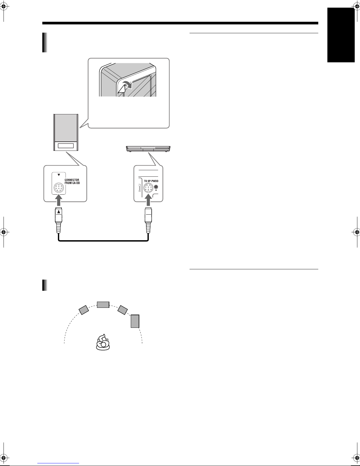
Connecting the subwoofer to the
main unit
Peel off the protective
Subwoofer
Rear view
System cable (supplied)
Align the 5 marks on the terminals and the system cable.
sheets from both sides of
the subwoofer.
Main unit
Rear view
■ CAUTION
• An incorrect connection may damage the speakers. Properly connect the cables to the speaker
terminals.
• Do not short-circuit the ª and · speaker terminals. Doing so may damage the main unit.
• The supplied speakers are manufactured exclusively for use with the supplied main unit as
parts of the DD-8/DD-3 system. Do not connect
the supplied speakers to devices other than the
supplied main unit. Doing so may damage the
speakers.
• Do not connect other speakers together with the
supplied speakers. The change in impedance
may damage the main unit and the speakers.
• Improper speaker cable connection spoils the
stereo effect and sound quality.
• Most of the supplied speakers* are magnetically
shielded, but color irregularity may occur on the
TV depending on some conditions. To prevent
color irregularity, set up the speakers following
the instructions below.
1. Turn off the main power of the TV before
setting up the speakers.
2. Place the speakers enough distance from the
TV so that they do not cause color irregularity
on the TV.
3. Wait for approximately 30 minutes before
turning on the main power of the TV again.
* The subwoofer for DD-3 is not magnetically
shielded. With the exception of this
subwoofer, the supplied speakers are
magnetically shielded.
English
Preparation
Speaker layout
Center surround speaker
Left speaker
Right speaker
Subwoofer
10
Page 16
Preparation (continued) Do not turn on the power until you complete the connection.
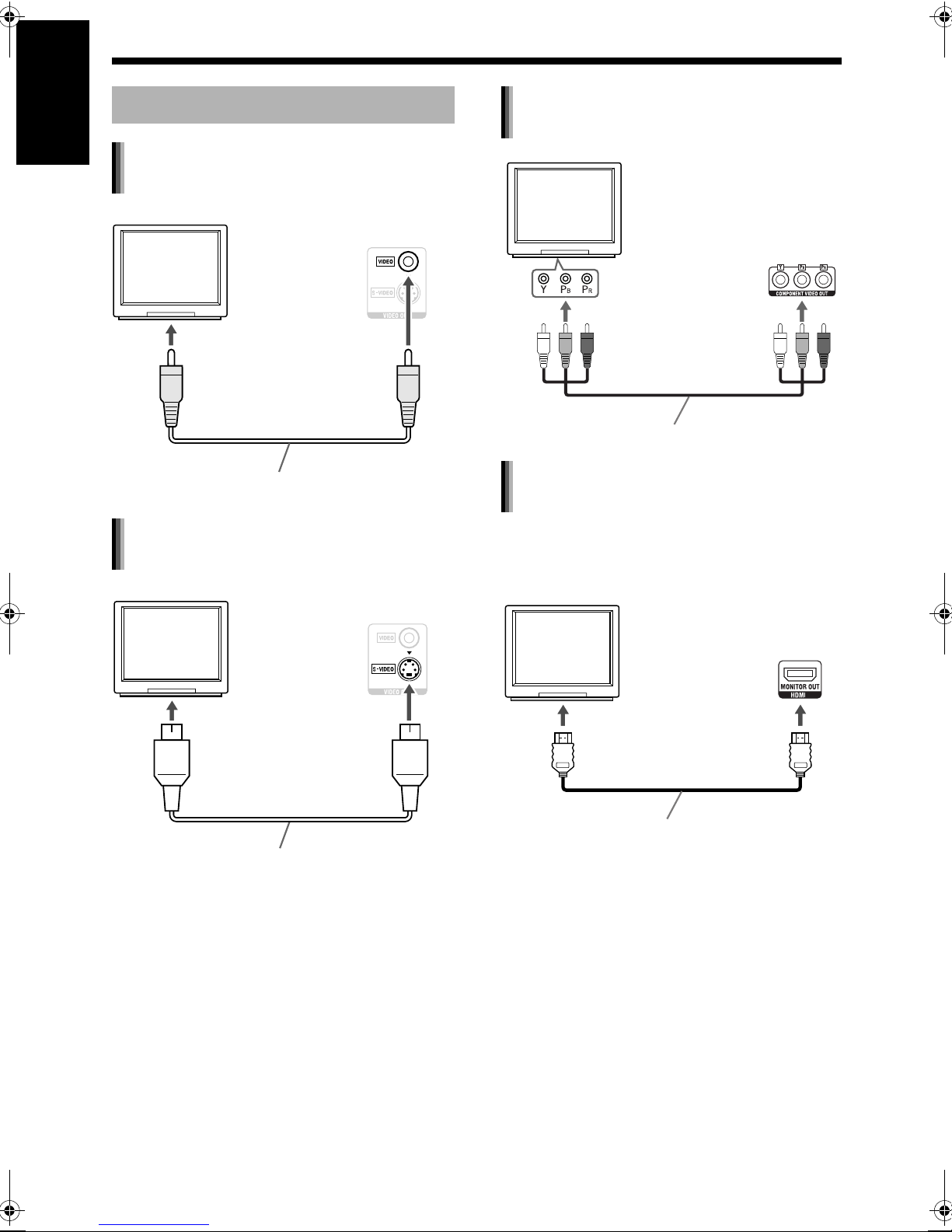
Connecting a TV
English
Connecting a TV with the [VIDEO]
terminal
TV
Preparation
To a video terminal
Composite video cable (supplied)
Connecting a TV with the [S-VIDEO]
terminal
TV
Main unit
(rear view)
Main unit
(rear view)
Connecting a TV with the
[COMPONENT VIDEO OUT] terminals
TV
Main unit
(rear view)
To component
terminals
Component video cable (not supplied)
Connecting a TV with the [HDMI]
terminal
This system can output uncompressed digital
video signals to a TV compatible with HDMI (High
Definition Multimedia Interface).
TV
Main unit
(rear view)
To an S-video terminal
S-video cable (not supplied)
To an HDMI terminal
HDMI cable (not supplied)
Select “HDMI” for the monitor out type. (Refer to
page 13.)
11
Page 17
NOTE
• This system supports up to HDMI version 1.0.
The HDMI video signal type can be checked with
the “HDMI” indicator in the display window.
(Refer to “Selecting the video signal type” shown
on the right.)
• If the picture is distorted while an HDMI TV is
connected, turn off the main unit and turn it on
again.
• A TV compatible with HDCP (High-Bandwidth
Digital Content Protection) can also be connected to the [HDMI] terminal, so that the
uncompressed HD video signal type can be output as well.
■ CAUTION
• Do not connect an S-video cable and a component video cable at the same time. Otherwise
the picture may not be played back properly.
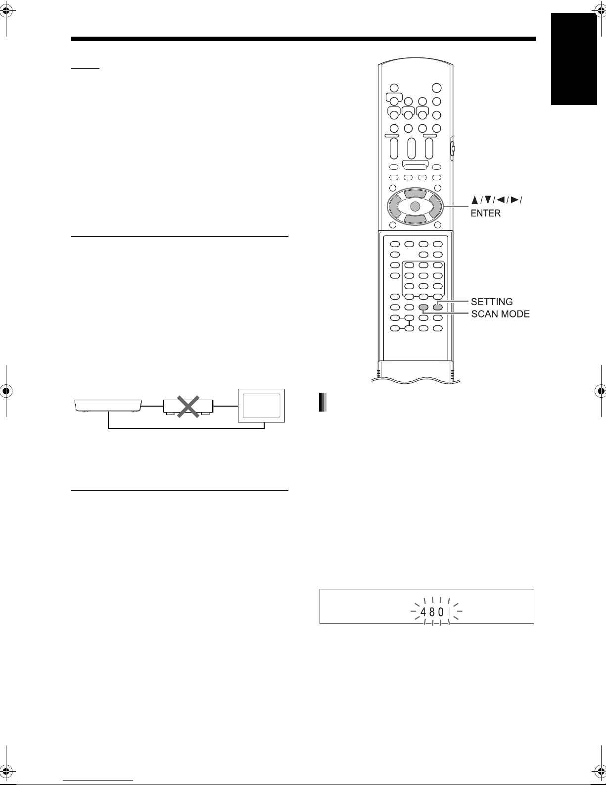
• Connect the main unit directly to a TV (or a monitor) without routing through a video cassette
recorder (VCR). Otherwise picture distortion
may occur during playback. (Routing the connection through a VCR, however, does not affect
the audio quality.)
English
Preparation
TV
Main unit
• Connecting the main unit to a VCR-built-in-TV
may also cause picture distortion during playback.
VCR
Direct connection
(or monitor)
Selecting the video signal type
To view an image on the TV screen, select the
video signal type correctly according to the TV
after connecting the main unit to the TV.
1 Turn on the main unit. (Refer to
“Connecting the power cable” on
page 15 and “Turning on the main
unit” on page 16.)
2 Hold down [SCAN MODE] for 2 or
more seconds.
• The current video signal type flashes.
Example:
(Continued on the next page)
12
Page 18
Preparation (continued)
Do not turn on the power until
you complete the connection.
For the locations of the remote
control buttons, refer to page 12.
3 Press 2 or 3 to select the video
English
Preparation
signal type suitable for the TV.
• When the TV is connected to the [VIDEO]
terminal or the [S-VIDEO] terminal, the
video signal type can be selected as
instructed below.
- Select “480I” for a TV only compatible with
interlaced video siginal.
- Select “480P” for a TV equipped with a
component terminal and compatible with
progressive video signal.
• When the TV is connected to the [HDMI] terminal, the video signal type can be selected
as instructed below.
- Select “AUTO” for normal usage (the initial
setting).
- Select “480P” or “720P” as needed.
NOTE
• “480” and “720” refer to the number of the scanning lines. Generally, the larger the number, the
better picture that can be obtained.
• “I” refers to the interlaced format. “P” refers to
the progressive format. A better picture can be
obtained in the progressive format than in the
interlaced format.
• When an HDMI video signal is output, the
“HDMI” indicator lights up in the display window.
• When an HD video signal (720p) is output, the
“HD” indicator lights up.
• When “480P” or “720P” is selected, the “PROGRESSIVE” indicator lights up in the display
window.
NOTE
• The picture may be distorted when you press
[ENTER], but this is not a malfunction of the system.
• To check the compatibility of your TV, contact
your local JVC customer service center.
• All JVC-manufactured progressive TVs and
high-definition TVs are fully compatible with this
system.
• Even if the main unit is turned off, the video signal type setting is stored.
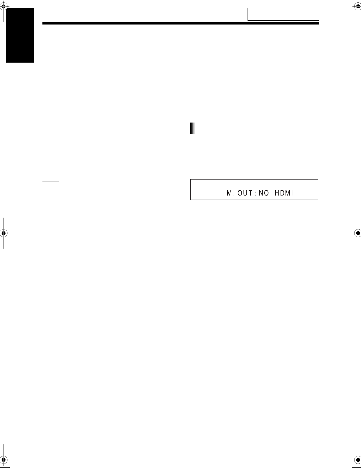
Selecting the monitor out type
To view an image on the TV, select the monitor out
type as well as the video signal type.
1 Press [SETTING].
2 Press 5 or / to display “M.OUT”.
3 Press 2 or 3 to select “HDMI” or
“NO HDMI”.
• When using an HDMI cable to connect a TV
to the main unit, select “HDMI”.
• When an HDMI cable is not connected,
select “NO HDMI” (the initial setting).
4 Press [ENTER] or wait for a short
time.
4 Press [ENTER].
• The selected video signal type is displayed
in the display window for a short time.
13
Page 19
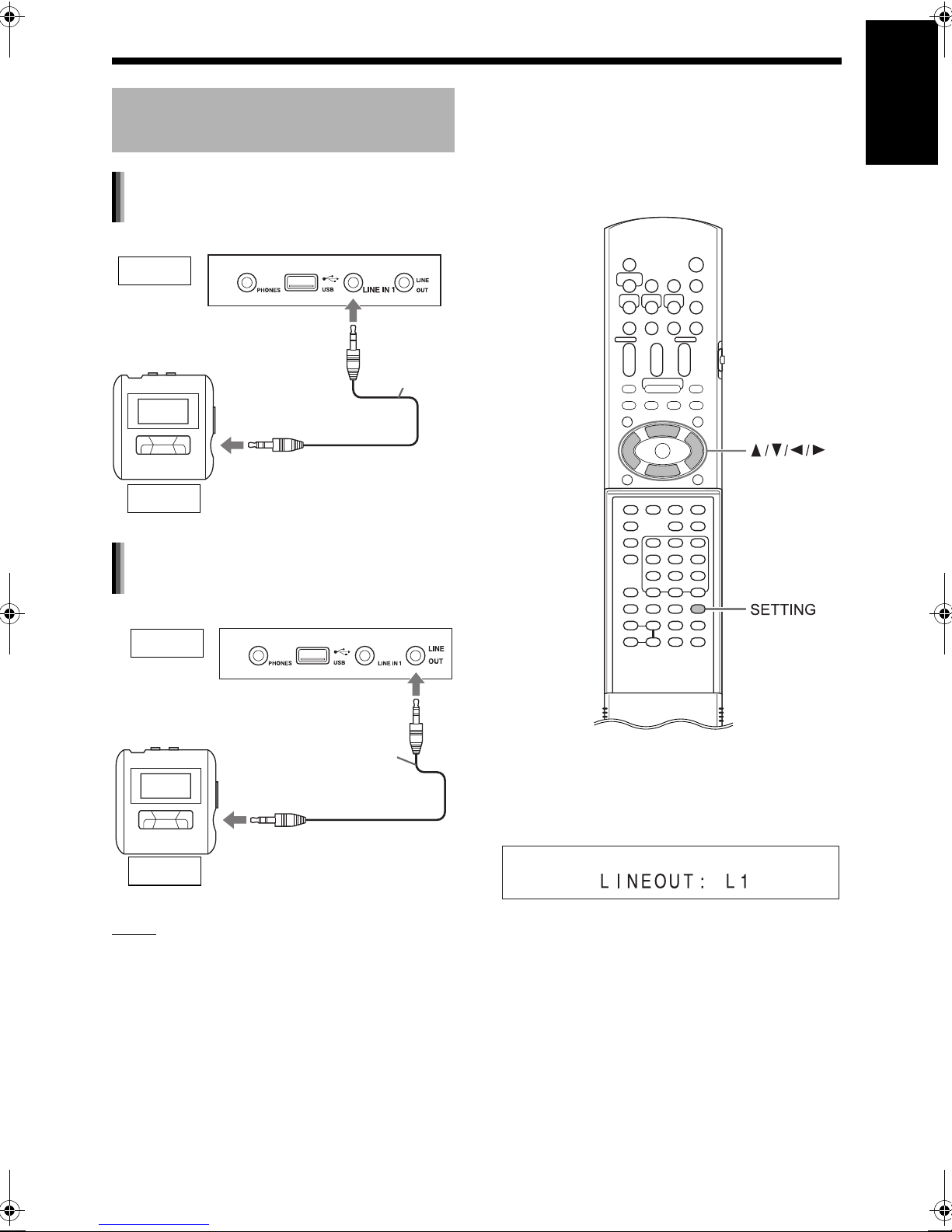
Connecting a portable digital
audio player
Listening to analog sound from a
portable digital audio player
Main unit (front view)
Input
Audio cable
(not supplied)
To an audio output terminal
■ Selecting the analog output level of the
[LINE OUT] terminal
You can lower the analog output level to prevent
the system from producing unnecessarily loud
sound. Controlling the level may also be helpful for
recording sound from the system to other devices.
English
Preparation
Output
Portable digital audio player or
other audio device
Outputting analog sound to a
portable digital audio player
Output
To an audio input terminal
Portable digital audio player or
Input
NOTE
• Signals input from the [LINE IN 1] and [LINE IN
2] terminals are not output to the [LINE OUT] terminal.
other audio device
Main unit (front view)
Audio cable
(not supplied)
1 Press [SETTING].
2 Press 5 or / to select “LINEOUT”
in the display window.
3 Press 2 or 3 to select “L1” or
“L2”.
- “L1” for normal usage (the initial setting)
- “L2” for higher level
14
Page 20
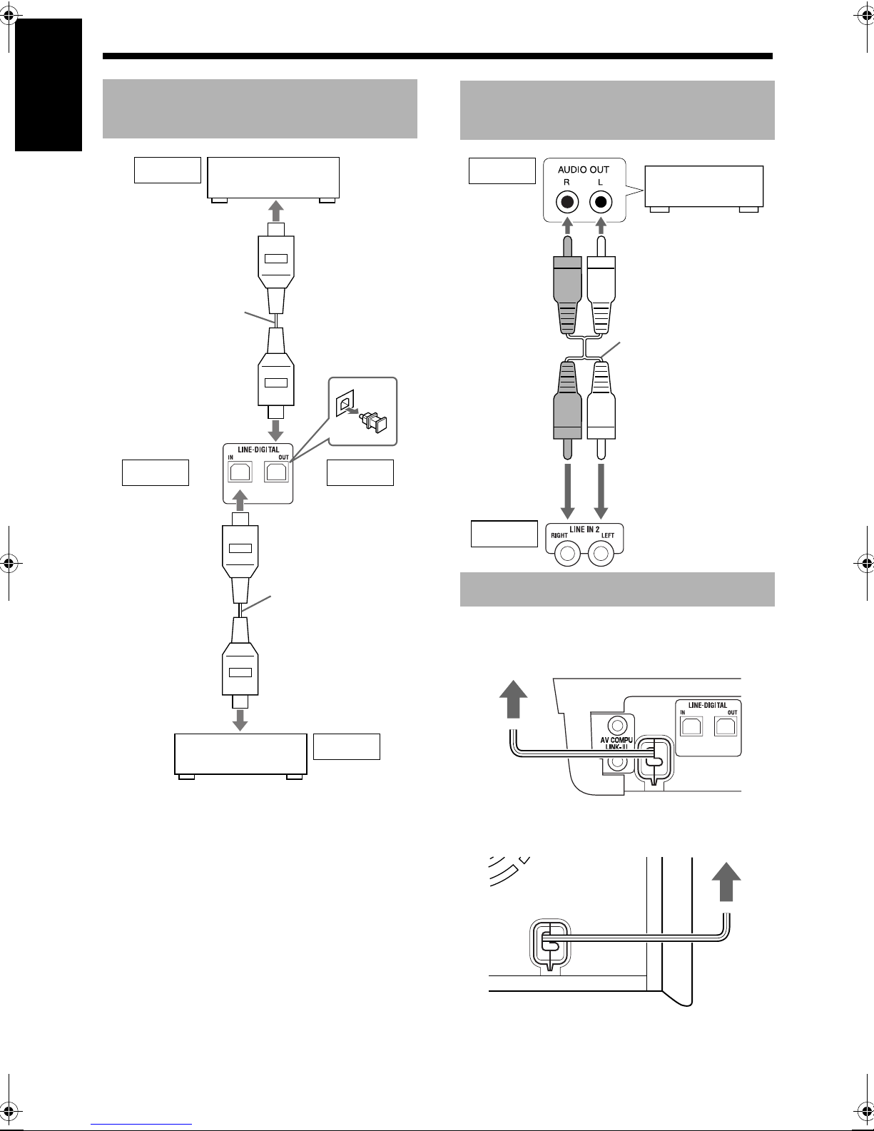
Preparation (continued) Do not turn on the power until you complete the connection.
Connecting other digital
English
audio devices
Input
To an optical digital
Preparation
input terminal
Optical digital cable
(not supplied)
Input Output
AV amplifier with a
built-in decoder
Main unit
(rear view)
Connecting other analog
audio devices
Output
Audio device
Audio cable
(not supplied)
Optical digital cable
(not supplied)
To an optical digital
output terminal
MD player or satellite receiver
Output
Input
Main unit
(rear view)
Connecting the power cable
■ Main unit
Main unit
AC outlet
■ Subwoofer
Subwoofer (rear view)
(rear view)
AC outlet
15
Page 21

Basic operations
Remote control
mode selector
Turning on the main unit
Press [F AUDIO].
• Press [F AUDIO] again to turn off the main
unit.
• With the power off, pressing any of the following
buttons also turns on the main unit.
- [DVD/CD 3], [USB 3], [NETWORK 3],
[LINE], [FM/AM] or [OPEN/CLOSE 0] on the
remote control
- 3, 0 or [SOURCE] on the main unit
The function assigned to the button starts work-
ing at the same time.
Adjusting the volume
English
Basic operations
Number
buttons
■ CAUTION
• Slide the remote control mode
selector to [AUDIO].
Using the number buttons
Examples:
5: [5]
15: [ 10] →
[1] → [5]
Press [AUDIO VOL +/–].
• Adjustable volume range is from 0 to 40.
• You can also adjust the volume by pressing
[VOLUME+/
NOTE
• Refer to page 17 for adjusting the volume of the
center surround speaker/subwoofer.
• Refer to page 17 for adjusting the volume balance between the left and right speakers.
–
] on the main unit.
Turning off the sound
temporarily
Press [MUTING].
• Press [MUTING] again to restore the sound.
When the main unit is turned off once and turned
on again, the sound also is restored.
150: [ 10] → [ 10] → [1] → [5] → [0]
16
Page 22
Basic operations (continued)
Sharpening the voice sound
English
This function allows you to easily understand dialog recorded on the disc/file even with the volume
down low.
Press [CLEAR VOICE].
• Each time you press [CLEAR VOICE], the clear
voice function turns on and off.
This indicator lights up when the
Basic operations
NOTE
• This function is effective when receiving the center channel signal with surround sound, or when
the surround mode is activated even with stereo
sound (refer to page 33).
clear voice function is activated.
Adjusting the bass/treble
Adjusting the volume of the
center surround speaker/
subwoofer
1 Press [CH LEVEL] to repeatedly
select “SURR” (the center surround speaker) or “SUBWFR” (the
subwoofer) in the display window.
2 Press [+] or [
ume.
NOTE
• Adjustable volume range is from –6 to +6.
–
] to adjust the vol-
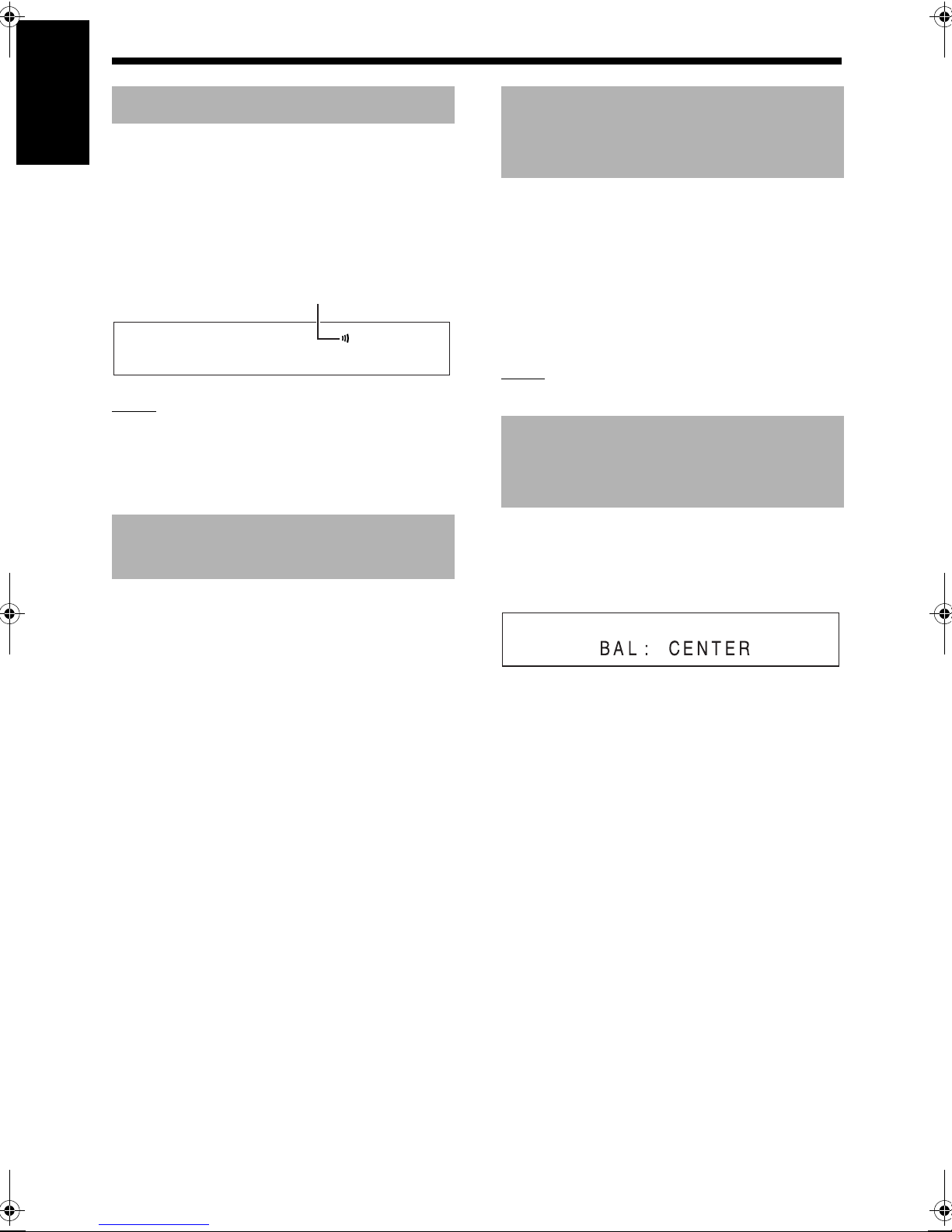
Adjusting the volume balance
between the left and right
speakers
1 Press [SETTING].
sound
1 Press [BASS/TREBLE] repeatedly
to select “BASS” or “TREBLE” in
the display window.
2 Press [+] or [
quality.
• Adjustable sound quality is from –5 to +5.
–
] to adjust the sound
2 Press 5 or / to display “BAL: ” in
the display window.
3 Press 2 or 3 to adjust the volume
balance.
• “CENTER” (the initial setting) is displayed
when the volume of the left and right speakers are the same.
• You can adjust the volume range respectively for the left and right speakers. Adjust-
–
able volume range is from
21 to –1.
17
Page 23
For the locations of the remote
control buttons, refer to page 16.
Changing the brightness of
the display window
Press [DIMMER].
• Each time you press [DIMMER], the display
changes in the display window as follows.
- “DIMMER 1”
The display window becomes darker than the
normal display brightness.
- “DIMMER 2”
The display window becomes darker than
“DIMMER 1”.
- “DIMMER AUTO”
When a video disc/file is played back, the display window becomes darker automatically.
- “DIMMER OFF”
The normal display brightness is restored.
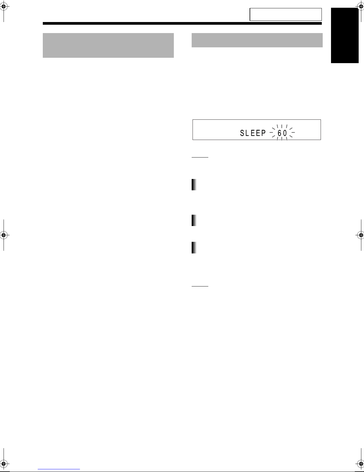
Using the sleep timer
When the time you specify elapses, the main unit
automatically turns off.
Press [SLEEP].
• Each time you press [SLEEP], the time indicated
in the display window changes. You can set the
time to 10, 20, 30, 60, 90, 120 or 150 minutes.
Example : Display when the sleep timer is set
to 60 minutes
NOTE
• When the sleep timer is activated, the display
window becomes darker automatically.
Changing the remaining time
Press [SLEEP] repeatedly to select the
time again.
Confirming the remaining time
English
Basic operations
Press [SLEEP] once.
Canceling the sleep timer
Press [SLEEP] repeatedly until
“SLEEP” disappears.
NOTE
• Turning off the main unit cancels the sleep timer.
18
Page 24
Basic operations (continued)
For the locations of the remote
control buttons, refer to page 16.
Auto standby function
English
If no sound is produced for 3 minutes, the main
unit automatically turns off.
This function is available when a disc/file is
selected as the source.
You cannot use this function when a radio broadcast or a device connected to the [LINE IN 1],
[LINE IN 2] or [LINE-DIGITAL IN] terminals is
selected as the source.
Basic operations
Activating the auto standby function
■ When a disc/file is selected as the source
Press [A.STANDBY].
.
• Pressing [A.STANDBY] once again deactivates
the function. (The display window changes to
“A.STANDBY OFF”.)
“A. STANDBY” indicator
Performance of the auto standby
function
When playback of a disc/file finishes, the auto
standby function starts a countdown.
At this time, the “A.STANDBY” indicator
starts flashing.
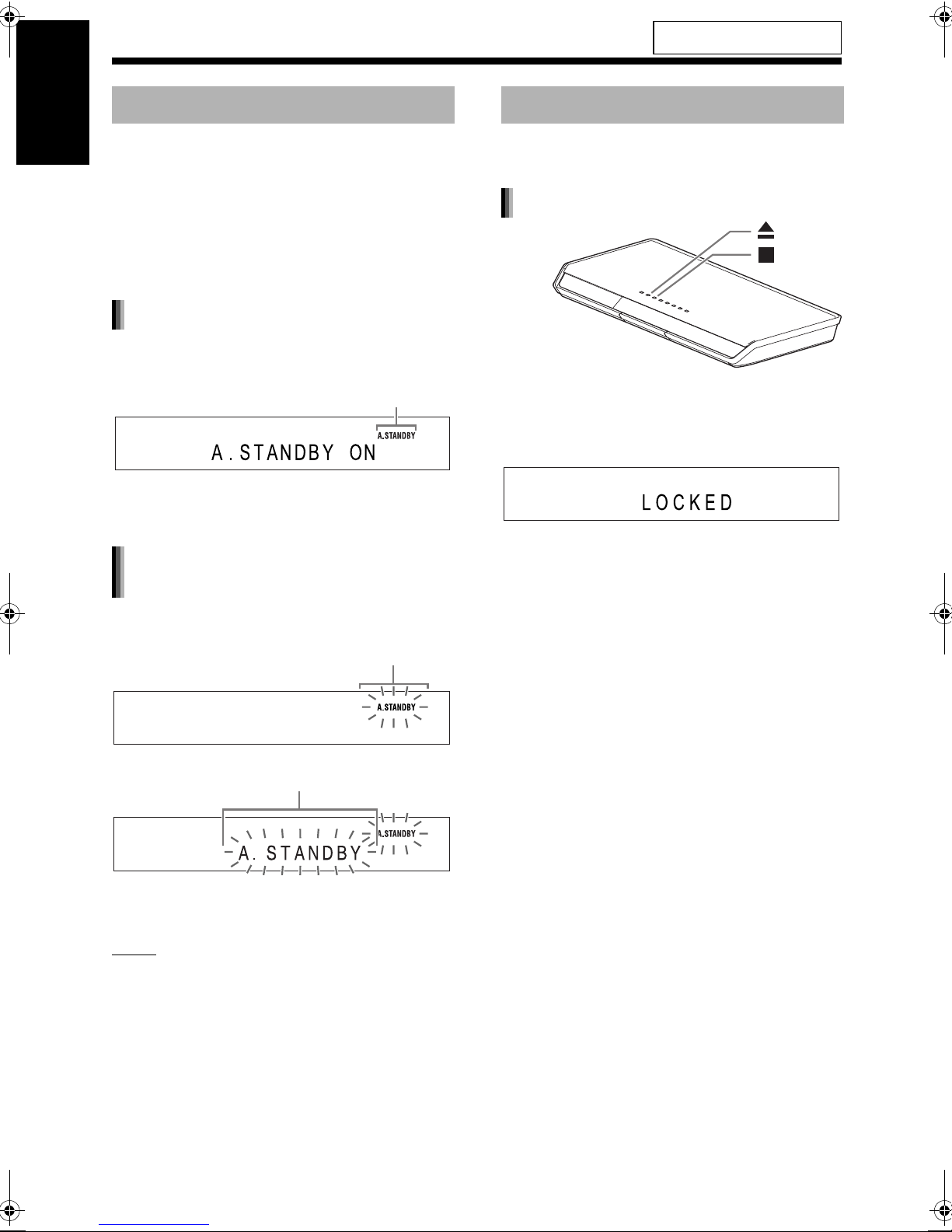
Locking disc ejection
You can lock the disc tray to prevent the disc from
being ejected.
Setting the disc ejection lock
■ When the main unit is turned off
Press 0 while holding down 7 on the
main unit.
• Repeat this step to cancel the disc ejection lock.
(The display window changes to “UNLOCKED”.)
20 seconds before the main unit turns off,
“A.STANDBY” starts flashing.
When no operation is carried out for 3 minutes, the
main unit automatically turns off.
NOTE
• Leaving the volume at “0” is not the same as
producing no sound, and therefore does not start
the auto standby function.
19
Page 25
Listening to radio broadcasts
Selecting a radio station
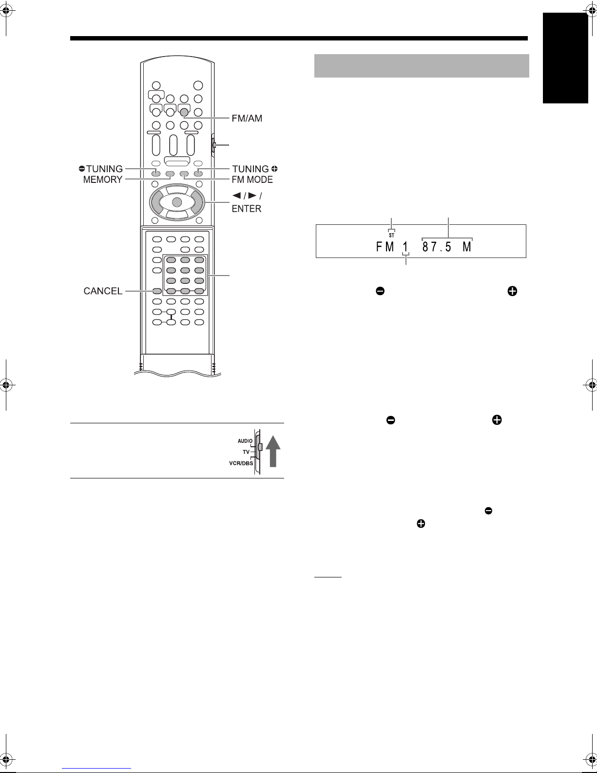
1 Press [FM/AM] to select “FM” or
“AM” in the display window.
• Each time you press [FM/AM], the band tog-
Remote control
mode selector
Number
buttons*
* For the number button usage, refer to “Using the
number buttons” on page 16.
■ CAUTION
• Slide the remote control mode
selector to [AUDIO].
gles between “FM” and “AM”.
• Repeatedly pressing [SOURCE] on the
main unit can also select a radio broadcast
as the source.
Example: Display when an FM radio broadcast
is received
Stereo indicator
Preset number (Refer to page 21.)
2 Press [ TUNING] or [TUNING ]
repeatedly to select a radio station.
• When the main unit has receive an FM stereo broadcast, the “ST” (stereo) indicator
lights up in the display window.
• You can also select a radio station using the
automatic tuning.
■ Automatic tuning
Hold down [ TUNING] or [TUNING ] until
the frequency starts changing, and then
release the button.
• When the main unit has received a broadcast, the frequency automatically stops
changing.
• You can select a specific radio station while
searching for a broadcast. Press [ TUNING] or [TUNING ] to stop the automatic
tuning when the desired frequency appears
in the display window.
English
Frequency (M: MHz/k: kHz)
Listening to radio broadcasts
NOTE
• If an FM stereo broadcast is difficult to hear
because of noise, you may be able to hear the
broadcast more easily by pressing [FM MODE]
to switch the sound to monaural reception. In
this case, the “MONO” (monaural) indicator
lights up in the display window. To return the
sound to stereo reception, press [FM MODE]
again.
20
Page 26
Listening to radio broadcasts (continued)
For the locations of the remote
control buttons, refer to page 20.
Tuning in to a preset radio
English
station
Presetting radio stations in the main unit allows
you to easily tune in to a radio station.
Presetting radio stations
You can store up to 30 FM radio stations and up to
15 AM radio stations.
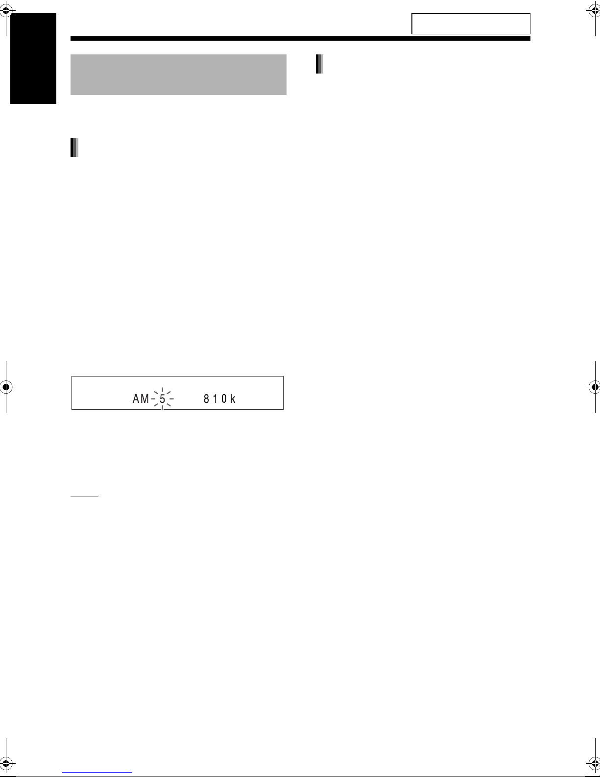
1 Select a radio station you want to
store.
• Refer to “Selecting a radio station” on page
20.
Listening to radio broadcasts
2 Press [MEMORY].
• The preset number flashes in the display
window.
3 While the preset number is flash-
ing, press the number buttons to
select the preset number.
Tuning in to a preset radio station
■ When an FM or AM radio broadcast is
selected as the source
Press the number buttons to select
the preset number.
• You can also select the preset number by pressing 2 or 3.
Example: When storing the radio station “AM
810 kHz” to the preset number “5”
4
While the selected number is flashing, press [MEMORY] or [ENTER].
• “STORED” appears and the selected radio
station is stored.
NOTE
• When you store a radio station to a preset number to which another radio station has previously
been stored, the newly set radio station replaces
the previously stored radio station.
• You can also use 2 or 3 to select the preset
number in step 3.
21
Page 27
Basic operations of disc/file playback
Playing back a disc
This part explains playing back the types of discs
shown above.
Remote control
mode selector
Number
buttons*
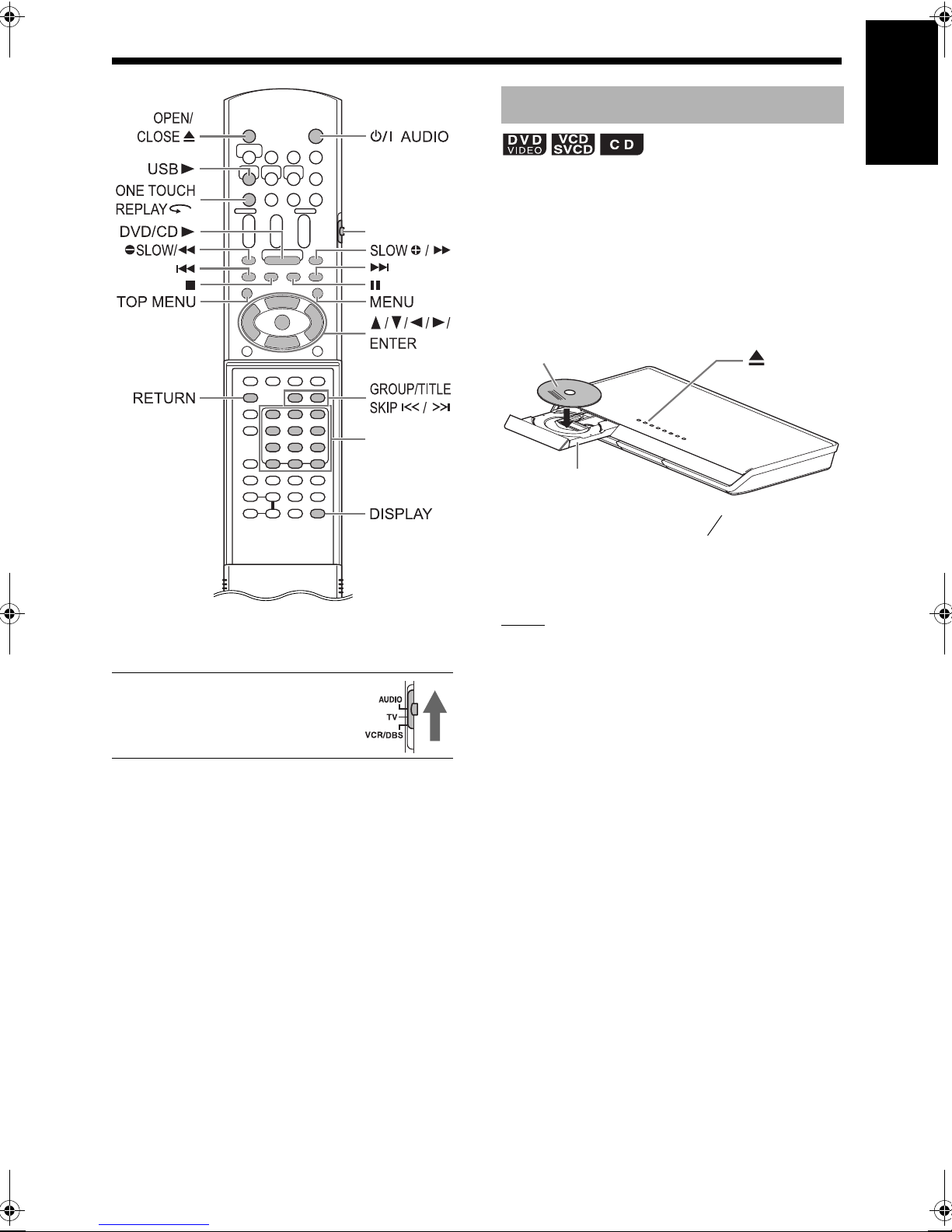
1 Press [OPEN/CLOSE 0] on the
remote control or
unit.
• The disc tray ejects.
0 on the main
2 Place a disc.
Printed surface
Disc tray
English
Basic operations of disc/file playback
* For the number button usage, refer to “Using the
number buttons” on page 16.
■ CAUTION
• Slide the remote control mode
selector to [AUDIO].
• To play back an 8-cm (3 ″) disc, place it
on the inner hollow of the disc tray.
3
16
3 Press [DVD/CD 3].
NOTE
• Instead of step 3, you can use the buttons on the
main unit. Repeatedly pressing [SOURCE] can
select the disc as the source, and pressing 3
starts playback.
• A menu screen may appear on the TV screen
after DVD playback starts. In such a case, operate the menu screen, referring to “Selecting a
track from the menu screen” on page 29.
• If you perform an operation, such as changing
the source quickly or loading an incompatible
disc (refer to pages 49-51), the disc may not be
played back or ejected. In this case, turn off the
main unit and turn it on again by using F on the
main unit.
22
Page 28
Basic operations of disc/file playback (continued)
Playing back a file
English
This part explains playing back 1) files recorded on
the loaded disc, and 2) files recorded on a USB
mass storage class device connected to the main
unit. The operation is explained with a display of
MP3 files as an example.
NOTE
• When files of different types are recorded on a
disc or connected USB mass storage class
device, select the file type before playback.
(Refer to “FILE TYPE” on page 38.)
1 Prepare the system for file
playback by following the
operations below.
■ When you want to play back files on a disc
Basic operations of disc/file playback
Place a disc on the disc tray.
• Refer to steps 1 and 2 on page 22.
■ When you want to play back files on a USB
mass storage class device
Connect the USB mass storage class
device to the [USB] terminal on the
front of the main unit.
Main unit (front view)
• The main unit does not charge a USB mass storage class device connected to the [USB] terminal.
2 Press [DVD/CD 3] or [USB 3].
NOTE
• You can also use the buttons on the main unit.
Repeatedly pressing [SOURCE] can select the
disc/file as the source, and pressing 3 starts
playback.
• If you select another source while “READING” is
displayed in the display window, sound is not
produced until reading of the files is finished.
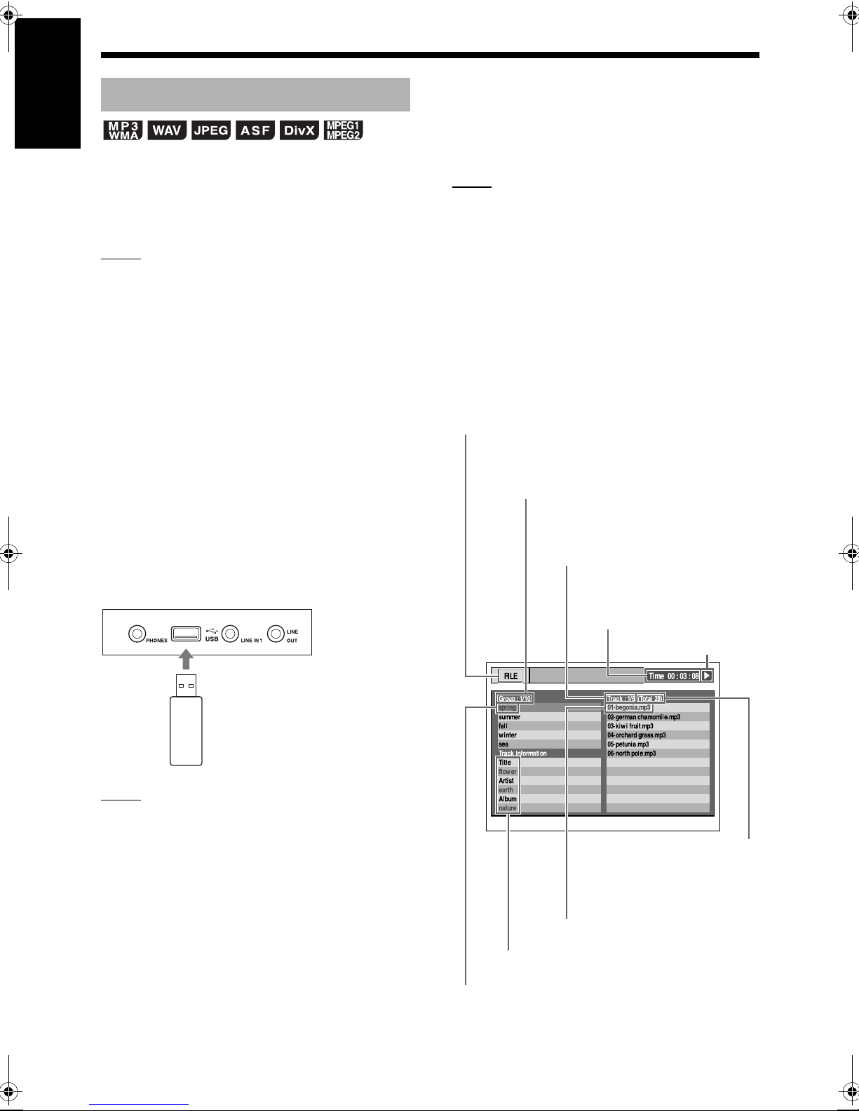
3 Press 7 to stop playback.
• The menu screen appears on the TV
screen.
When a file recorded on the connected USB mass
storage class device is selected as the source,
“USB” is displayed.
Numbers of the current group and total groups
recorded on the loaded disc or connected USB
mass storage class device
Numbers of the current track (file)
and total tracks (files) included in the
current group
Elapsed playback time of the
current track (MP3/WMA/WAV
file only)
Flash memory device, portable
digital audio player or other USB
mass storage class device
NOTE
• Copyrighted files cannot be played back.
• This system cannot recognize a USB mass storage class device whose rating exceeds 5V/
500mA.
• When connecting a USB mass storage class
device, refer also to its manual.
• When using a USB cable for connecting a USB
mass storage class device, its length should be
less than 1 m (3′3″).
• Connect a USB mass storage class device
directly to the main unit without routing through a
USB hub. Otherwise a malfunction may occur.
• Before disconnecting the USB mass storage
class device, make sure that playback is
stopped.
Playback status
Number of the total tracks
(files) recorded on the loaded
disc or connected USB mass
storage class device
Current track (file)
Tag information (MP3/WMA file only)
Current group
23
Page 29
For the locations of the remote
control buttons, refer to page 22.
NOTE
• Depending on the file type, the menu screen
appears before you press 7.
4 Press 5 , /, 2 or 3 to select a
group and track.
NOTE
• You can also use [GROUP/TITLE SKIP / ] to
select a group, and the number buttons, 4 or
¢ to select a track.
5 Press [DVD/CD 3] or [USB 3].
NOTE
• If you have skipped step 3, you do not have to
proceed to step 5.
Slide-show playback
• JPEG files are continuously played back from
the selected file.
• Display time for a file in slide-show playback is
approximately 3 seconds.
• Press [ENTER] to view only the selected file.
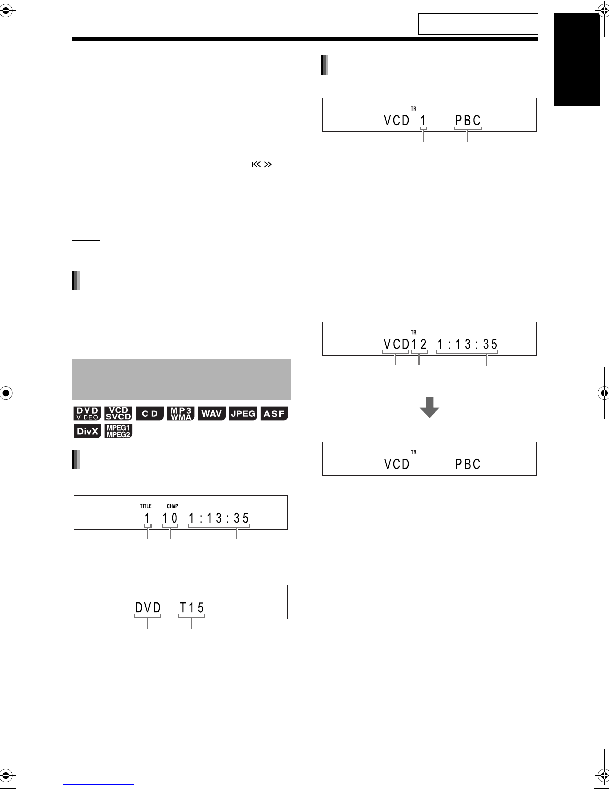
VCD/SVCD
■ When a disc is played back
Track number
• You can control the playback of a PBC compatible disc using a menu screen.
• To cancel the PBC function, follow the instructions below.
- Specify the track number using the number
buttons when the disc is stopped.
- Specify the track number using 4 or ¢
when the disc is stopped, and then press
[DVD/CD 3].
• Press [RETURN] to go back to the upper layer
during PBC playback.
■ When a disc is stopped
Playback control
English
Basic operations of disc/file playback
Display window on the main
unit for disc/file types
DVD VIDEO
■ When a disc is played back
Title number Elapsed
■ When a disc is stopped
Disc type Total number of titles
Chapter
number
playback time
Disc type Total number
of tracks
(When the PBC function is activated)
Total playback
time
24
Page 30
Basic operations of disc/file playback (continued)
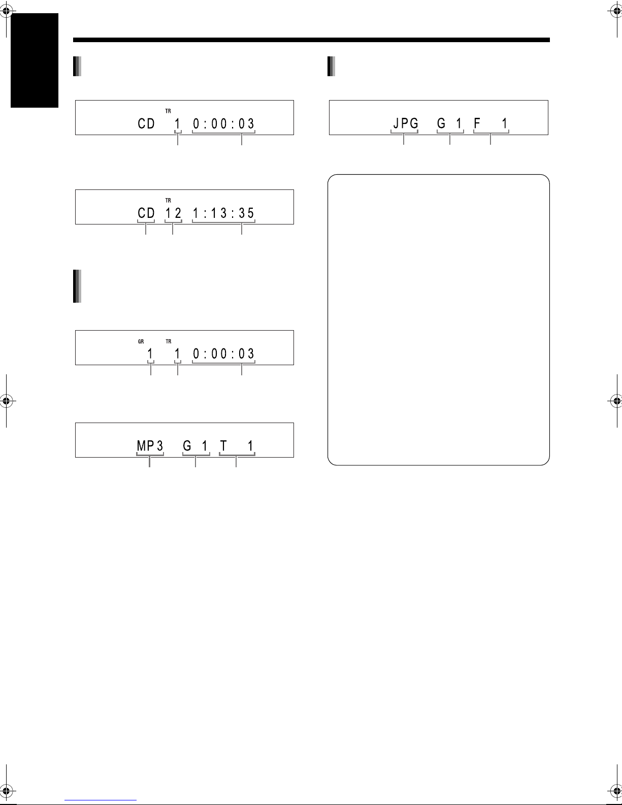
CD
English
■ When a disc is played back
Track number Elapsed playback
■ When a disc is stopped
Disc type Total number
MP3/WMA/WAV/ASF/DivX/MPEG1/
MPEG2 file
Basic operations of disc/file playback
■ When a file is played back
of tracks
time
Total playback
time
JPEG file
■ When a file is played back or stopped
File type
Messages on the TV screen
When a DVD VIDEO is selected as the source,
the messages shown below are displayed on
the TV screen to indicate the disc status.
NOW READING:
Appears when the main unit is reading the disc
information. Wait for a short time.
REGION CODE ERROR!:
Appears when the region code of the disc does
not match the code the main unit supports.
(Refer to page 49.)
NO DISC:
Appears when no disc is loaded.
Group
number
File number
Group
number
Track
number
Elapsed
playback time
■ When a file is stopped
File type
Group
number
Track
number
■ Changing the display in the display window
(Only for MP3/WMA files)
For an MP3/WMA file, you can change the display
in the display window to see tag information and a
file name.
When a disc/file is played back
Press [DISPLAY] repeatedly.
• Each time you press [DISPLAY], the display
changes in the display window.
OPEN:
Appears when the disc tray is opening.
CLOSE:
Appears when the disc tray is closing.
CANNOT PLAY THIS DISC:
Appears when an unplayable disc is attempted
to be played back.
25
Page 31

For the locations of the remote
control buttons, refer to page 22.
Guide icons on the TV screen (on-screen
guide)
: Play
: Pause
: Fast reverse/fast forward search
Slow motion playback (reverse/
:
forward directions)
: Containing multi-view angles (Refer to
page 30.)
: Containing multi-audio languages
(Refer to page 30.)
: Containing multi-subtitle languages
(Refer to page 30.)
: The disc/file cannot accept the opera-
tion you have attempted.
Indicators in the display window
related to the speaker sound
The indicators light up in the display window to
show the input signals and the speakers in use.
The input signal is DOLBY DIGITAL.
The input signal is processed using
DOLBY DIGITAL PRO LOGIC II.
The input signal is DTS.
The input signal is LPCM.
The sound is produced from the subwoofer.
The “ ”, “ ”, “ ” or “ ” indicator in
the frame ( ) shows the speaker producing the sound.
The input signal is for the left speaker.
The input signal is for the center surround
speaker.
The input signal is for the right speaker.
The input signal is LFE.
The input signal is for the left speaker on
the center surround speaker.
The input signal is monaural or 2-channel
Dolby surround.
The input signal is for the right speaker on
the center surround speaker.
The surround mode is activated.
English
Basic operations of disc/file playback
26
Page 32

Basic operations of disc/file playback (continued)
Stopping playback
English
■ When a disc/file is played back
Press 7.
Resuming playback
(only for the loaded disc)
When playback is stopped in the middle, playback
can be started from the stopped position.
Temporarily stopping playback
■ When a disc/file is played back
Basic operations of disc/file playback
Follow any of the operations below.
Press 7 once.
Press [F AUDIO] to turn off the main unit.
*1
Pausing playback
■ When a disc/file is played back
Press 8.
• Press [DVD/CD 3] or [USB 3] to return to the
normal playback.
Advancing the picture frame
by frame
■ When a disc/file is paused
Press 8 repeatedly.
*2
*1 “RESUME” is displayed in the display window.
After this operation, the position where playback
has been stopped is stored even when the main
unit is turned off by pressing [F AUDIO].
*2 This operation does not work for a CD.
Starting playback from the stored
position
Press [DVD/CD 3] .
NOTE
• This function does not work in program playback
or random playback.
• You can deactivate the resume playback function. (Refer to“RESUME” on page 39.)
Clearing the stored position
Press 7 twice.
NOTE
• The stored position is also cleared if the disc tray
is opened.
27
Page 33

For the locations of the remote
control buttons, refer to page 22.
Fast reverse/fast forward
search
There are 2 methods.
■ When a disc/file is played back
• Press 1 or ¡.
- Each time you press ¡, the speed
increases. To restore the normal speed, press
[DVD/CD 3] or [USB 3].
• Hold down 4 or ¢.
NOTE
• For some discs/files, sound is intermittent or no
sound is produced during fast reverse/fast forward search.
• The selectable speeds and displays vary by the
disc/file type.
Playing back from a position
10 seconds before
Slow motion playback
■ When a disc is paused
Press [ SLOW] or [SLOW ].
• Each time you press [ SLOW] or [SLOW ],
the speed increases.
• Pressing [DVD/CD 3] cancels this function and
starts normal playback.
NOTE
• No sound is produced.
• The picture motion in the reverse direction may
not be smooth.
• For a VCD or SVCD, slow motion playback can
be used in the forward direction only.
Skipping to the beginning of a
chapter/track/file
English
Basic operations of disc/file playback
■ When a disc is played back
Press [ONE TOUCH REPLAY ].
NOTE
• You cannot go back to the previous title.
(PBC off)
■ When a disc/file is played back
Press 4 or ¢ repeatedly.
• Press [GROUP/TITLE SKIP / ] to select the
title or group.
28
Page 34

Basic operations of disc/file playback (continued)
For the locations of the remote
control buttons, refer to page 22.
Selecting a chapter/track
English
using the number buttons
(PBC off)
■ When a disc/file is played back
Press the number buttons to select
the chapter number or track number.
Skipping at approximately 5
minute intervals
You can skip within a file at approximately 5 minute
intervals. This is useful especially when you want
to skip within a long file.
■ When a disc/file is played back
Basic operations of disc/file playback
Press 2 or 3.
• Each time you press 2 or 3, the playback position skips to the beginning of the previous or
next interval. Each interval is approximately 5
minutes.
NOTE
• Intervals are automatically assigned from the
beginning of a file.
• You can use this function only within the same
file.
Selecting a track from the
menu screen
■ When a disc is stopped or played back
1 Press [MENU] or [TOP MENU].
• The menu screen is displayed.
2 Press 5, /, 2 , 3 or the number
buttons to select the desired track.
3 Press [ENTER].
NOTE
• You can use this function only when a menu
screen is recorded on the disc.
• For a VCD/SVCD, [MENU] and [TOP MENU]
may be unavailable in step 1. In this case, press
[RETURN] once or more.
• For a VCD/SVCD, you cannot use 5, /, 2 or
3 in step 2.
• For a VCD/SVCD whose menu screen has a
couple of pages, you can change the page by
pressing 4 or ¢ in step 2.
• Playback may start for some discs without
pressing [ENTER] in step 3.
29
Page 35

Convenient functions of disc/file playback
Selecting the audio language,
subtitle language and view
angle
■ When a disc/file is played back
Remote control
mode selector
Number
buttons*
Press the desired button shown below.
• Each time you press the button, the audio language, subtitle language or view angle changes.
Function Button Available disc/file
Audio
language
Subtitle
language
View
angle
TV screen (example for the subtitle language)
[AUDIO]
[SUBTITLE]
[ANGLE]
: Audio language
: Subtitle language
: View angle
English
Convenient functions of disc/file playback
* For the number button usage, refer to “Using the
number buttons” on page 16.
■ CAUTION
• Slide the remote control mode
selector to [AUDIO].
NOTE
• The audio language, subtitle language and view
angle can also be changed by pressing 5 or /.
• You can only select these function settings when
the disc/file contains multiple audio languages,
subtitle languages or view angles.
• When a language code such as “AA” and “AB” is
displayed, refer to “Language codes” on page
40.
• You can also use the menu bar to set the functions. Refer to page 35.
• “ST”, “L” and “R” displayed when playing back a
VCD or SVCD, respectively, indicate “Stereo”,
“Left sound” and “Right sound”.
30
Page 36

g
Convenient functions of disc/file playback (continued)
Playing back a disc/file in the
English
desired order (Program
playback)
Display for a VCD/SVCD/CD
• Select a track number.
Track indicator
(only for the loaded disc)
You can program a maximum of 99 tracks. The
same track can be programmed more than once.
■ When a disc/file is stopped
1 Press [PLAY MODE] repeatedly to
display “PROGRAM” in the display
window.
Example: Display for a CD
Convenient functions of disc/file playback
Example: TV screen for a CD (Program screen)
2 Press the number buttons to pro-
gram tracks.
Track number Pro
Example: TV screen for a CD (Program screen)
• You can program up to 99 tracks.
NOTE
• Instead of using the number buttons, when you
press [ENTER] in the “Track/Chapter” column on
the TV screen, “ALL” appears and all the tracks
in the selected group are programmed.
• You can erase the programmed tracks one by
one from the bottom of the list on the program
screen by pressing [CANCEL] repeatedly.
• You can erase the whole program at once by
pressing
• Ejecting the disc or turning off the main unit also
erases the program.
7
.
ram number
3 Press [DVD/CD 3].
Display for an MP3/WMA/WAV file
• Select a group number, and then a track number.
Group indicator Track indicator
Group number Track
number
31
Confirming the program
■ When a disc/file is played back
Press 7.
• Playback stops and the program screen appears
on the TV screen.
Canceling program playback
Program number
■ When a disc/file is stopped
Press [PLAY MODE] repeatedly to display an item other than “PROGRAM”
in the display window.
• This operation does not erase the program.
Page 37

For the locations of the remote
control buttons, refer to page 30.
Playing back a disc/file in a
random order (Random
playback)
(only for the loaded disc)
■ When a disc/file is stopped
1 Press [PLAY MODE] repeatedly to
display “RANDOM” in the display
window.
• Selecting an item other than “RANDOM”
cancels random playback.
2 Press [DVD/CD 3].
NOTE
• Each chapter or track is played back only once.
• Ejecting the disc or turning off the main unit cancels random playback.
Magnifying the picture
English
■ When a disc is played back or paused
1 Press [ZOOM].
• Each time you press the button, the picture
magnification changes in the display window.
2 Select the portion you want to
magnify by using 5, /, 2 or 3.
• To return to normal playback, select
“ZOOM x 1” in step 1.
NOTE
• When you magnify a picture, image quality may
be deteriorated or the image may be distorted.
Convenient functions of disc/file playback
32
Page 38

ALL
ALL
Convenient functions of disc/file playback (continued)
Playing back a disc/file
English
repeatedly (Repeat playback)
(PBC off)
■ When a disc/file is played back
Press [REPEAT].
• Each time you press [REPEAT], the repeat
mode changes.
Convenient functions of disc/file playback
Display on
the
TV screen
TITLE
Display in
the
display
window
REPEAT
TITLE
ALL
or
REPEAT
REPEAT
ALL
ALL
GROUP
or
REPEAT
REPEAT
GROUP
GROUP
REPEAT
or
2
CHAP*
2
REPEAT
TRACK*
2
CHAP*
TRACK*
REPEAT
TRACK
OFF
or
no display
*1
Repeats the whole program during program
REPEAT
OFF
playback.
*2
“STEP” is displayed during program/random
playback.
Indica-
tor in the
display
window
GR
2
Usage for
the repeat
mode
Repeats
the
current title.
Repeats all
1
tracks*
.
Repeats
the
current
group.
Repeats the
current
chapter.
Repeats
the
current
track.
Cancels
repeat.
Selecting the surround mode
Press [SURROUND MODE].
• Each time you press [SURROUND MODE], the
display changes in the display window as follows.
- “AUTO SURROUND”
When a multi-channel signal is input, surround
sound is automatically produced.
- “MOVIE/M.MUSIC”
Surround sound suitable for a movie or multichannel signal is produced.
- “WIDE/2chMUSIC”
When a 2ch signal is input, surround sound is
produced. The sound is broader than the one
with “MOVIE/M.MUSIC”.
-“SUPER WIDE”
Surround sound broader than the one with the
“WIDE/2chMUSIC” is produced.
- “SURROUND OFF”
Turns off the surround sound.
NOTE
• When a surround-processed signal is input while
“AUTO SURROUND”, “MOVIE/M.MUSIC”,
“WIDE/2chMUSIC” or “SUPER WIDE” is
selected, the “SURROUND” indicator in the display window lights up.
• Depending on the signal type, surround sound
may not be produced as the surround mode setting.
• During playback, when you change the surround
mode setting, sound from the [LINE OUT] and
[LINE-DIGITAL OUT] terminals may be intermittent. Before recording sound to another device,
select the desired surround mode setting.
NOTE
• Repeat playback can also be set using the menu
bar. (Refer to page 35.)
• You can also specify a part to be played back
repeatedly by using A-B repeat playback. (Refer
to page 36.)
• The repeat mode is automatically canceled if
there is a file that cannot be played back.
33
Page 39

For the locations of the remote
control buttons, refer to page 30.
Adjusting the picture quality
(VFP)
■ When a disc is played back or paused
1 Press [VFP].
• The current settings are displayed.
TV screen (example)
Selected VFP mode
2 Press 2 or 3 to select VFP mode.
• Each time you press 2 or 3, VFP mode
changes on the TV screen as follows.
- “NORMAL”
For normal playback. (You cannot adjust
the image quality.) Go to step 7.
- “CINEMA”
Suitable for viewing a movie in a dim room.
(You cannot adjust the image quality.)
Go to step 7.
- “USER1/USER2”
You can adjust the image quality.
Go to step 3.
3 Press 5 or / to select the item
you want to adjust.
• Each time you press 5 or /, the item
changes on the TV screen as follows.
- “GAMMA”
Controls the brightness of neutral tints
while maintaining the brightness of dark
and light portions. (Selectable options:
“LOW”, “MID” and “HIGH”)
- “BRIGHTNESS”
Controls the brightness of the display.
(Setting range: –8 to +8)
- “CONTRAST”
Controls the contrast of the display. (Setting range: –12 to +12)
-“SATURATION”
Controls the saturation of the display. (Setting range: –16 to +16)
-“TINT”
Controls the tint of the display. (Setting
range: –16 to +16)
- “SHARPNESS”
Controls the sharpness of the display.
(Selectable options: “LOW” and “HIGH”)
4 Press [ENTER].
TV screen (example)
5 Press 5 or / to change the value.
6 Press [ENTER].
English
Convenient functions of disc/file playback
• To adjust other items, go back to step 3.
7 Press [VFP].
NOTE
• This function does not work when the [HDMI]
terminal on the main unit is connected to a TV.
• If no operation is made for several seconds during the procedure, the settings made so far are
automatically stored.
• “VFP” stands for “Video Fine Processor”.
34
Page 40

Using the status bar and the menu bar
Function list
English
■ When a disc/file is played back
1 Press [ON SCREEN] twice.
TV screen for a DVD VIDEO (example)
Status bar
Menu bar
2 Press 2 or 3 to select an item you
want to operate, and then press
[ENTER].
• To turn off the menu bar, press [ON
SCREEN].
Information displayed on the status
bar
DVD VIDEO
Convenient functions of disc/file playback
Sound signal type
VCD/SVCD/CD/ASF/DivX/MPEG1/MPEG2
(the example below is for a CD)
Playback mode status
NOTE
* The playback status has the same meaning of
the mark on the on-screen guide. (Refer to page
26.)
Current title number
Playback status*
Current chapter number
Time
(VCD/SVCD/CD)
Current track number
(ASF/DivX/MPEG1/MPEG2 file)
Repeat mode status
Time
Playback
status*
To select the settings for those items listed below
without a description of their operation, press 5 or
/ to select an item and press [ENTER].
Time
Time display
selection
Repeat mode
Time search
Chapter search
Audio language
Subtitle language
View angle
Changes the time information in the
display window and the status bar.
Each time [ENTER] is pressed, the
display changes on the menu bar.
DVD VIDEO (operating during playback)
TOTAL :
T.REM : Remaining time of the cur-
Time : Elapsed playback time of
REM : Remaining time of the cur-
CD (operating during playback)/
VCD/SVCD
Time : Elapsed playback time of
REM : Remaining time of the cur-
TOTAL : Elapsed playback time of
T.REM : Remaining time of the disc.
Refer to page 33.
(For A-B repeat playback, refer to
page 36.)
Refer to page 36.
DVD VIDEO (chapter search)
Selects a chapter. Press the number
buttons to enter the chapter number
and press [ENTER].
Examples:
24 : [ 10] → [2] → [4]
DVD VIDEO/VCD/SVCD/DivX
Refer to page 30.
DVD VIDEO/SVCD/DivX
Refer to page 30.
DVD VIDEO
Refer to page 30.
Elapsed playback time of
the current title.
rent title.
the current chapter.
rent chapter.
the current track.
rent track.
the disc.
5 : [5]
35
Page 41

For the locations of the remote
control buttons, refer to page 30.
Playing back a specified part
repeatedly (A-B repeat
playback)
(PBC off)
You can play back the desired part repeatedly by
specifying a start point (A) and an end point (B).
■ When a disc is played back
1 Press [ON SCREEN] twice.
• The menu bar appears. (Refer to page 35.)
2 Press 2 or 3 to select .
3 Press [ENTER].
4 Press 5 or / to select “A-B”.
5 Press [ENTER] at the start point of
the part to be repeated (specifying
point A).
• The icon on the menu bar is .
6 Press [ENTER] at the end point of
the part to be repeated (specifying
point B).
• The icon on the menu bar is .
• The “ ” and “A-B” indicators light up in the
display window and the part between points
A and B is played back repeatedly.
Canceling A-B repeat playback
There are 2 methods.
• Press 7.
• Select . (Select and press
[ENTER] twice.)
NOTE
• You can use A-B repeat playback only within the
same title or track.
• You cannot use A-B repeat playback during program playback, random playback or repeat playback.
Designating the time
(Time search)
(PBC off)
■ When a disc is played back
1 Press [ON SCREEN] twice.
• The menu bar appears. (Refer to page 35.)
2 Press 2 or 3 to select .
3 Press [ENTER].
4 Enter the time using the number
buttons.
Example:
When you want to play back a DVD VIDEO from
the position of (0 hour) 23 minutes 45 seconds,
press the number buttons in the order of [ 0 ], [ 2 ],
[ 3 ], [ 4 ] and [ 5 ].
• You can skip entering the minute and second settings.
• If the incorrect value is entered, press 2 to
delete the values and enter values again.
5 Press [ENTER].
• To turn off the menu bar, press [ON
SCREEN].
NOTE
• This function does not work during program
playback or random playback.
• For a CD, you can use this function any time.
• Time search for a DVD VIDEO is from the beginning of the title.
• Time search for a VCD, an SVCD and a CD is as
follows:
- When the disc is stopped, time search is from
the beginning of the disc.
- When the disc is played back, time search is
within the track currently being played back.
English
Convenient functions of disc/file playback
36
Page 42

Changing the initial settings with the preference screen
Basic operations
English
You can change the initial settings of the main unit
with the preference screen according to the environment where the main unit is used.
Remote control
mode selector
Convenient functions of disc/file playback
■ When a disc/file is stopped or no disc is
loaded (“NO DISC” is displayed in the display window)
1 Press [SET UP].
• The preference screen appears on the TV
screen.
Example:
2 Use 5, /, 2, 3 and [ENTER] to
control the preference screen.
• Proceed with operations by following the
description on the TV screen.
■ CAUTION
• Slide the remote control mode
selector to [AUDIO].
NOTE
• The top and bottom of the preference screen
may not be displayed on a wide TV. Adjust the
picture size on the TV.
LANGUAGE
Items Contents
MENU
LANGUAGE
AUDIO
LANGUAGE
SUBTITLE Select the subtitle language for the
ON SCREEN
LANGUAGE
NOTE
• If the selected language is not recorded on the
disc/file, the optimum language set for the disc/
file is displayed.
• For a language code such as “AA”, refer to the
“Language codes” on page 40.
Select the language for the DVD
VIDEO menu screen.
Select the audio language for the DVD
VIDEO.
DVD VIDEO.
Select the language displayed on the
preference screen.
37
Page 43

PICTURE
English
Items
MONITOR
TYPE
PICTURE
SOURCE
Contents ( : initial setting)
Select the display method suitable for
your TV.
4 : 3 PS (Pan Scan) :
For a TV with conventional 4:3 aspect
ratio. When a wide screen picture is
input, the left and right edges of the picture are not shown on the screen. (If the
disc/file is not compatible with Pan Scan,
the picture is displayed at the Letterbox
ratio.)
4 : 3 LB (Letterbox)
For a TV with conventional 4:3 aspect
ratio. When a wide screen picture is
input, black bars appear on the top and
bottom of the screen.
16 : 9 :
For an ordinary wide TV.
Select the item suitable to the video
source.
AUTO
:
The video source type (a video or film) is
automatically selected.
FILM :
To view a film or video recorded with the
progressive scan method.
VIDEO (ACTIVE) :
Suitable for playing back a video with a
lot of action.
VIDEO (NORMAL) :
Suitable for playing back a video without
a lot of action.
:
Items
SCREEN
SAVER
FILE TYPE When files of different types are recorded
HDMI DVI
COLOR
HDMI OUT You can select the video signal type out-
Contents ( : initial setting)
You can turn or OFF the screen
saver. The screen saver activates when
there is no operation made for approximately 5 minutes since a still picture was
last displayed.
NOTE
• This function does not work when this
system outputs the video signal via the
[HDMI] terminal.
on a disc or connected USB mass storage class device, select the file type
before playback.
AUDIO
For MP3/WMA/WAV files.
STILL PICTURE :
For JPEG files.
VIDEO :
For ASF/DivX/MPEG1/MPEG2 files.
You can select the settings for the picture
appearance (image quality, color intensity
and black fading) on the TV connected to
the [HDMI] terminal.
STANDARD :
For normal usage.
ENHANCE
The main unit automatically adjusts the
picture appearance.
put from the [HDMI] terminal.
AUTO
For normal usage. The main unit automatically selects the output video signal
type according to the TV connected to
the [HDMI] terminal.
RGB :
Select this item if no picture appears on
the TV with the “AUTO” setting. The output video signal type is set to the RGB
signal.
ON
:
:
:
Convenient functions of disc/file playback
38
Page 44

Changing the initial settings with the preference screen (continued)
?? AUDIO
English
Items
DIGITAL
AUDIO
OUTPUT
DOWN MIX Select the signal suitable to the device
Convenient functions of disc/file playback
D (Dynamic).
RANGE
COMPRESSION
HDMI
AUDIO OUT
Contents (
Select the output signal type suitable to
the device connected to the [LINE-DIGITAL OUT] terminal. Refer to “List of relationships of DIGITAL AUDIO OUTPUT
preference items and output signal” on
page 40.
PCM ONLY :
Device corresponding only to linear PCM.
DOLBY DIGITAL/PCM :
Dolby Digital decoder or device having
the same function.
STREAM/PCM
DTS/Dolby Digital decoder or device having the same function.
connected to the [LINE-DIGITAL OUT]
terminal. Set “DOWN MIX” only when
“DIGITAL AUDIO OUTPUT” is set to
“PCM ONLY”.
DOLBY SURROUND :
Dolby Pro Logic decoder-built-in device.
STEREO
Ordinary audio device.
To correct the difference between high
volume and low volume when playing
back with low volume (only for a DVD
recorded with Dolby Digital).
WIDE RANGE :
For enjoying the original full dynamic
range of surround sound without effects.
NORMAL
For normal usage. Surround sound is
compressed to a certain level.
You can select whether or not the audio
signal from the [HDMI] terminal is output.
:
ON
The audio signal from the [HDMI] is output.
:
OFF
The audio signal from the [HDMI] is not
output.
NOTE
• Depending on the connected TV, when
“HDMI AUDIO OUT” is set to “ON”,
only PCM signals can be output via an
HDMI cable.
: initial setting)
:
:
:
?? OTHERS
Items
RESUME
ON
SCREEN
GUIDE
AV
COMPULINK
MODE
DivX
REGISTRATION
NETWORK
SETUP
Contents (
Select or OFF. (Refer to page 27.)
Select or OFF. (Refer to page 26.)
When you want to control the main unit
and the connected TV or other devices at
the same time, select a setting according
to the type of terminal on the device connected to the main unit. (Refer to “Using
the AV COMPU LINK function” on page
46.)
DVD1 :
When connecting to the video 3 or DVD
input terminal on the TV.
DVD2
When connecting to the video 1 input terminal on the TV.
DVD3 :
When connecting to the video 2 input terminal on the TV.
The main unit has its own registration
code. You can confirm the registration
code, when necessary. Once you have
played back a disc/file on which the registration code is recorded, the registration
code of the main unit is overwritten for
copyright protection.
Refer to the separate volume of the operation manual for the network function.
: initial setting)
ON
ON
:
39
Page 45

List of relationships of DIGITAL AUDIO OUTPUT preference items and output
signal
English
Playback disc/file
48 kHz, 16/20/24 bits linear PCM
DVD VIDEO
96 kHz linear PCM DVD VIDEO
DTS DVD VIDEO DTS bit stream 48 kHz, 16 bits stereo linear PCM
DOLBY DIGITAL DVD VIDEO DOLBY DIGITAL bit stream
CD/VCD/SVCD
DTS CD DTS bit stream 44.1 kHz, 16 bits linear PCM
MP3/WMA/DivX file 32/44.1/48 kHz, 16 bits linear PCM
STREAM/PCM DOLBY DIGITAL/PCM PCM ONLY
DIGITAL AUDIO OUTPUT preference
48 kHz, 16 bits stereo linear PCM
48 kHz, 16 bits stereo lin-
ear PCM
44.1 kHz, 16 bits stereo linear PCM
48 kHz, 16 bits linear PCM
NOTE
• Among DVD VIDEOs without copyright protection, there may be some DVD VIDEOs that output a 20- or
24- bit signal through the [LINE-DIGITAL OUT] terminal.
Language codes
Code Language Code Language Code Language Code Language
AA Afar GD Scots Gaelic MI Maori SL Slovenian
AB Abkhazian GL Galician MK Macedonian SM Samoan
AF Afrikaans GN Guarani ML Malayalam SN Shona
AM Ameharic GU Gujarati MN Mongolian SO Somali
AR Arabic HA Hausa MO Moldavian SQ Albanian
AS Assamese HI Hindi MR Marathi SR Serbian
AY Aymara HR Croatian MS Malay (MAY) SS Siswati
AZ Azerbaijani HU Hungarian MT Maltese ST Sesotho
BA Bashkir HY Armenian MY Burmese SU Sundanese
BE Byelorussian IA Interlingua NA Nauru SV Swedish
BG Bulgarian IE Interlingue NE Nepali SW Swahili
BH Bihari IK Inupiak NL Dutch TA Tamil
BI Bislama IN Indonesian NO Norwegian TE Telugu
BN Bengali, Bangla IS Icelandic OC Occitan TG Tajik
BO Tibetan IW Hebrew OM (Afan) Oromo TH Thai
BR Breton JI Yiddish OR Oriya TI Tigrinya
CA Catalan JW Javanese PA Panjabi TK Turkmen
CO Corsican KA Georgian PL Polish TL Tagalog
CS Czech KK Kazakh PS Pashto, Pushto TN Setswana
CY Welsh KL Greenlandic PT Portuguese TO Tonga
DA Danish KM Cambodian QU Quechua TR Turkish
DZ Bhutani KN Kannada RM Rhaeto-Romance TS Tsonga
EL Greek KO Korean (KOR) RN Kirundi TT Tatar
EO Esperanto KS Kashmiri RO Rumanian TW Twi
ET Estonian KU Kurdish RU Russian UK Ukrainian
EU Basque KY Kirghiz RW Kinyarwanda UR Urdu
FA Persian LA Latin SA Sanskrit UZ Uzbek
FI Finnish LN Lingala SD Sindhi VI Vietnamese
FJ Fiji LO Laothian SG Sangho VO Volapuk
FO Faroese LT Lithuanian SH Serbo-Croatian WO Wolof
FY Frisian LV Latvian, Lettish SI Singhalese XH Xhosa
GA Irish MG Malagasy SK Slovak YO Yoruba
ZU Zulu
Convenient functions of disc/file playback
40
Page 46

Playing back sources from other devices
2 Start playback on the connected
English
device.
• Refer also to the operation manual for the
connected device.
3 Adjust the volume and make other
necessary settings.
• Refer to “Basic operations” on page 16.
Selecting the signal gain
You can select the gain of the signal from the
[LINE IN 1] and [LINE IN 2] terminals.
Use the initial settings for normal operation. If the
sound is too small or too loud, change the settings.
1 Press [LINE] repeatedly to select
“LINE 1” or “LINE 2” in the display
window.
Playing back sources from other devices
Selecting other devices as the
source
1 Press [LINE].
• Each time you press [LINE], the display
changes in the display window as follows.
- “LINE 1” for selecting the device con-
nected to the [LINE IN 1] terminal
- “LINE 2” for selecting the device con-
nected to the [LINE IN 2] terminals
- “LINE-DIGITAL” for selecting the digital
audio device connected to the [LINE-DIGITAL IN] terminal
• You can also select the connected device as
the source by repeatedly pressing
[SOURCE] on the main unit.
2 Hold down [ENTER].
• Each time you hold down [ENTER], the display changes as follows.
“LEVEL 1” : the initial setting for “LINE 2”
“LEVEL 2”
“LEVEL 3” : the initial setting for “LINE 1”
• The signal gain increases in the order of
“LEVEL 1”, “LEVEL 2” and “LEVEL 3”.
NOTE
• You can select the signal gain respectively for
“LINE 1” and “LINE 2”.
41
Page 47

QP LINK
When you start analog playback of a portable digital audio player connected to the [LINE IN 1] terminal while the main unit is off or another source is
selected, the main unit automatically turns on and
the source changes to the connected portable digital audio player. This function is called the quick
portable link function (QP LINK).
Activating QP LINK
Press [QP LINK] repeatedly to select
“QP ON” in the display window.
• To deactivate QP LINK, select “QP OFF”.
• You can set QP LINK when the main unit is both
on and off.
*1
Using QP LINK
2 Start playback on the portable dig-
ital audio player.
• If the main unit is off, the main unit automatically turns on.
• The source from the portable digital audio
player is automatically selected, “LINE 1” is
displayed and sound is produced.
NOTE
*1 When “QP ON” is displayed, “:ACT” or “:NO
ACT” is also displayed to indicate the status of
QP LINK. (According to the status of the main
unit, “:ACT” and “:NO ACT” changes automatically.)
- “QP ON :ACT” is displayed when QP LINK
is activated and available.
- “QP ON :NO ACT” is displayed when QP
LINK is activated but unavailable.
Pressing [QP LINK] once can be used to confirm the status of QP LINK.
English
Playing back sources from other devices
■ When “QP ON” is selected
1 Connect a portable digital audio
player to the [LINE IN 1] terminal
using an audio cable.
Main unit (front view)
Audio cable
(not supplied)
Output
Portable digital audio player or
other audio device
Selecting the sensitivity for QP LINK
If the sensitivity for the input audio signal is too
high, QP LINK may be activated even when the
portable digital audio player is not played back.
At this time, you can select the lower sensitivity.
Hold down [QP LINK].
• Each time you hold down [QP LINK], the display
changes in the display window as follows.
- “QP: LEVEL1” for normal usage (the initial set-
ting)
- “QP: LEVEL2” for lower sensitivity
42
Page 48

Operating other devices using the remote control
You can operate your TV, video cassette recorder
(VCR) and digital broadcast satellite (DBS) using
English
the remote control of this system.
Operating a TV using the
remote control
Setting the manufacturer code
1 Slide the remote control
mode selector to [TV].
Remote control
mode selector
• Hold down [TV F] until you finish step 4.
3 Press [ENTER] and release.
4 Press number buttons to enter the
manufacturer code.
Examples:
For a Hitachi TV: Press [1], then [0].
For a Toshiba TV: Press [0], then [8].
When the manufacturer of your TV has 2 or more
2 Hold down [TV F].
Number
buttons/
TV RETURN/
100+
Operating other devices using the remote control
codes, select the manufacturer codes in turn and
find the one that operates the TV and the remote
control properly.
Manufacturer Code
JVC 01
Hitachi 10
Magnavox 02
Mitsubishi 03
Panasonic 04, 11
Philips 15
RCA 05
Samsung 12, 18, 19, 20, 21
Sanyo 13, 14
Sharp 06, 16, 17
Sony 07
Toshiba 08
Zenith 09
43
5 Release [TV F].
NOTE
• Manufacturer codes are subject to change without notice. You may not be able to operate the
TV produced by the manufacturer.
• After replacing the batteries of the remote control, set the manufacturer code again.
Page 49

Using the remote control for the TV
operation
Operate the remote control by pointing it at the TV.
.
Remote
control button
F]
[TV
[TV/VIDEO]
[TV CHANNEL
–
]
+/
[TV VOL +/
Number but-
tons (1-9, 0,
100+)
[TV RETURN]
NOTE
• When the remote control mode selector is slid to
[TV], some buttons may not work.
Usage
Turns on/off the TV.
Changes between the TV and
video input.
Changes channels.
–
] Adjusts volume.
Slide the
remote control
mode selector
to [TV] in
advance.
Selects the
channels.
Changes
between the
previously
selected channel and the current channel.
Operating a VCR/DBS using
the remote control
Setting the manufacturer code
1 Slide the remote control
mode selector to [VCR/
DBS].
2 Press [VCR] or [DBS].
3 Hold down [VCR/DBS F].
• Hold down [VCR/DBS F] until you finish
step 5.
4 Press [ENTER] and release.
5 Press number buttons to enter the
manufacturer code.
Manufacturer codes for VCRs
Examples:
For a Hitachi VCR: Press [0], then [4].
For a Mitsubishi VCR: Press [1], then [3].
When the manufacturer of your VCR has 2 or more
codes, select the manufacturer codes in turn and
find the one that operates the VCR and the remote
control properly.
English
Operating other devices using the remote control
Manufacturer Code
JVC 01, 02, 03
Emerson 11, 26
Fisher 29
Funai 10, 14, 15, 16
Gold Star 12
Hitachi 04
Mitsubishi 13
NEC 25
Panasonic 07, 17
Philips 09
RCA
Samsung 24
Sanyo 21, 22, 23
Sharp 27, 28
Shintom 30
Sony 18, 19, 20
Zenith 08
05, 06
(Continued on the next page)
44
Page 50

Operating other devices using the remote control (continued)
Manufacturer codes for DBSs
Examples:
English
For an Echostar DBS: Press [2], then [1].
For a Sony DBS: Press [2], then [0].
When the manufacturer of your DBS has 2 or more
codes, select the manufacturer codes in turn and
find the one that operates the DBS and the remote
control properly.
Manufacturer Code
G. I. 01, 02, 03, 04, 05, 06, 07, 08
Echostar 21
Hamlin 15, 16, 17, 18
Jerrold 01, 02, 03, 04, 05, 06, 07, 08
Pioneer 13, 14
RCA 19
Scientific Atlanta 09, 10
Sony 20
Zenith 11, 12
6 Release [VCR/DBS F].
NOTE
• Manufacturer codes are subject to change with-
Operating other devices using the remote control
out notice. You may not be able to operate the
VCR/DBS produced by the manufacturer.
• After replacing the batteries of the remote control, set the manufacturer code again.
For the locations of the remote
control buttons, refer to page 43.
Using the remote control for the
VCR/DBS operation
Before the VCR/DBS operation, select the remote
control mode for the VCR/DBS.
1 Slide the remote control
mode selector to [VCR/
DBS].
2 Press [VCR] or [DBS].
Operate the remote control by pointing it at the
VCR/DBS.
Remote control button assigned for the VCR
operation
Remote control button Usage
[VCR/DBS F] Turns on/off the VCR.
[VCR] Selects the VCR input.
–
[TV CHANNEL +/
Number buttons
(1-10, 0, 10)
[DVD/CD 3] Starts playback.
7
8 Pauses playback.
¡ Fast-forwards the tape.
1 Fast-rewinds the tape.
Remote control button assigned for the DBS
operation
] Changes channels.
Selects the channels.
Stops playback.
Remote control button Usage
[VCR/DBS F] Turns on/off the DBS.
[DBS] Selects the DBS input.
–
[TV CHANNEL +/
Number buttons (1-9, 0,
10)
NOTE
• When the remote control mode selector is slid to
[VCR/DBS], some buttons may not work.
] Changes channels.
Selects the channels.
45
Page 51

Using the AV COMPU LINK function
When a JVC-manufactured TV with AV COMPU
LINK II or III terminals is connected to the main
unit using these terminals, operating either the TV
or the main unit controls the other device at the
same time.
Preparation for the AV
COMPU LINK function
NOTE
• Some JVC-manufactured TVs have terminals
labeled “AV COMPU LINK”. These terminals are
no different from the [AV COMPU LINK-III] terminal on the main unit of this system or, the “AV
COMPU LINK I/II” or “AV COMPU LINK” terminal on other JVC-manufactured systems.
• Refer to “OTHERS” on page 39 for determining
the “AV COMPULINK MODE” setting.
• Also refer to the manual of the TV to be connected to the main unit.
JVC-manufactured TV
Main unit (rear view)
Operating the AV COMPU
LINK function
1 Turn on the main power of the TV.
2 Play back a disc/file.
• Refer to pages 22 – 24.
• The power of the TV is turned on.
• The input mode on the TV changes to the
video 1, video 2 or video 3 (DVD) input.
NOTE
• You can use this function only when “NO HDMI”
is selected for the monitor out type. (Refer to
page 13.)
English
Reference
AV COMPU
LINK II or III
Connection cable (not supplied)
Input terminal on the TV“AV COMPULINK
MODE” setting
Video 1 DVD2
Video 2 DVD3
Video 3 DVD1
• The AV COMPU LINK function may not work for
some TVs when the main unit is connected to
the video 2 or video 3 terminal on the TV.
46
Page 52

Notes on operation
Suitable locations for the
English
main unit
To minimize the need for servicing and maintain
the high quality of this system, do not place the
main unit in the following locations:
• In a position subject to high humidity or consid-
Reference
erable dust
• On an uneven or unstable surface
• Near a heat source
• Near a computer, fluorescent light or other electric appliance
• In a small room with insufficient ventilation
• In a position exposed to direct sunlight
• In a position exposed to excessive cold
• In a position exposed to strong vibration
• Near a TV, other amplifier, or tuner
• Near a magnetic source
■ CAUTION
• The operating temperature of this system is 5°C
to 35°C (41°F to 95°F). Use in temperatures outside this range may cause a malfunction or damage the system.
Condensation
Under the following conditions, you may not be
able to operate this system properly due to condensation formed on the lens of the main unit:
• When you have just started an air conditioner to
warm your room
• When you have placed the main unit at an area
with high humidity
• When you have moved the main unit from a cold
place to a warm place
When condensation forms, leave the main unit
turned on, wait for approximately 1 or 2 hours, and
then operate the main unit.
License and trademark
• Manufactured under license from Dolby Laboratories. “Dolby” and the double-D symbol are
trademarks of Dolby Laboratories.
• “DTS” and “DTS Digital Surround” are registered
trademarks of Digital Theater Systems, Inc.
• This product incorporates copyright protection
technology that is protected by method claims of
certain U.S. patents and other intellectual property rights owned by Macrovision Corporation
and other rights owners. Use of this copyright
protection technology must be authorized by
Macrovision Corporation, and is intended for
home and other limited viewing uses only unless
otherwise authorized by Macrovision Corporation. Reverse engineering or disassembly is prohibited.
• DVD logo is a registered trademark of DVD Format/Logo Licensing Corporation.
• Official DivX
• Plays all versions of DivX® video (including
®
DivX
files
• DivX, DivX certified, and associated logos are
trademarks of DivX, Inc. and are used under
license.
• HDMI, the HDMI logo and High-Definition Multimedia Interface are trademarks or registered
trademarks of HDMI Licensing LLC.
• HDCP is the abbreviation of “High-Bandwidth
Digital Content Protection”, and is the high-reliable copy control technology licensed by Digital
Content Protection, LLC.
®
Certified product
6) with standard playback of DivX® media
Cleaning the main unit
When the operation panel becomes dirty, dust it
with a soft dry cloth. When the operation panel is
very dirty, wipe it with a cloth dampened with a
small amount of a neutral detergent, and then wipe
it with a soft dry cloth.
■ CAUTION
• Do not wipe the operation panel with thinners,
benzenes or other chemical agents. Do not
spray insecticides onto the operation panel.
These may cause discoloration and damage to
the surface.
47
Page 53

Notes on handling
Important cautions
Installation of the system
• Select a place which is level, dry and neither too
hot nor too cold; between 5°C and 35°C
(between 41°F to 95°F).
• Leave sufficient distance between the system
and the TV.
• Do not use the system in a place subject to
vibration.
Power cord
• Do not handle the power cord with wet hands!
• A small amount of power is always consumed
while the power cord is connected to the wall
outlet.
• When unplugging the power cord from the wall
outlet, always pull on the plug, not the power
cord.
Safety Precautions
Avoid moisture, water and dust
Do not place the system in moist or dusty places.
Avoid high temperatures
Do not expose the system to direct sunlight and do
not place it near a heating equipment.
When you are away
When away on travel or for other reasons for an
extended period of time, disconnect the power
cord plug from the wall outlet.
Do not block the vents
Blocking the vents may damage the system.
Care of the cabinet
When cleaning the system, use a soft cloth and follow the relevant instructions on the use of chemically-coated cloths. Do not use benzene, thinner or
other organic solvents including disinfectants.
These may cause deformation or discoloring.
English
Reference
To prevent malfunctions of the system
• There are no user-serviceable parts inside. If
anything goes wrong, unplug the power cord and
consult your dealer.
• Do not insert any metallic object into the system.
Note about copyright laws
Check the copyright laws in your country before
recording from CDs. Recording of copyrighted
material may infringe copyright laws.
If water gets inside the system
Turn the system off and disconnect the power cord
plug from the wall outlet, then call the store where
you made your purchase. Using the system in this
condition may cause fire or electrical shock.
• This product incorporates copyright protection technology that is protected by method claims of certain
U.S. patents and other intellectual property rights owned by Macrovision Corporation and other rights
owners. Use of this copyright protection technology must be authorized by Macrovision Corporation, and is
intended for home and other limited viewing uses only unless otherwise authorized by Macrovision
Corporation. Reverse engineering or disassembly is prohibited.
48
Page 54

Notes on discs/files
Playable disc/file types
English
Playable discs
Playable files recorded on a disc
Playable files recorded on a USB mass storage
class device
Reference
Playable files stored on a computer Refer to the separate volume of the operation manual for
*1
*1, *2
*3
DVD VIDEO, VCD, SVCD, CD, CD-R, CD-RW, DVD-R,
DVD-RW, +R, +RW
MP3, WMA, WAV, JPEG, ASF, DivX, MPEG1, MPEG2
the network function.
• Even though listed above, some types may be
unplayable.
1 Discs should be finalized before being played
*
back.
2 For files recorded on a DVD-R/DVD-RW, the
*
disc should be formatted with UDF Bridge.
3 This system may not recognize some USB
*
mass storage class devices. This system cannot play back a file whose data volume is more
than 2 gigabytes and a file whose data transfer
rate is more than 2 Mbps.
It is possible to play back finalized +R/+RW (DVD
Video Format only) discs. “DVD” lights on the front
display panel when a +R/+RW disc is loaded.
Some discs may not be played back because of
their disc characteristics, recording conditions, or
damage or stains on them.
Only sounds can be played back from the following
discs:
MIX-MODE CD CD-G
CD-EXTRA CD TEXT
Region code of DVD VIDEO
DVD VIDEO players and DVD VIDEO discs have
their own Region Code numbers. This system can
play back a DVD VIDEO whose Region Code
number includes the system’s Region Code, which
is indicated on the rear panel.
Examples:
If a DVD VIDEO with an improper region code
number is loaded, “REGION CODE ERROR!”
appears on the TV screen and playback cannot
start.
• On some DVD VIDEOs, VCDs, SVCDs or DivX
files, their actual operation may be different
from what is explained in this manual. This is
due to the disc/file programming and disc/file
structure, not a malfunction of this system.
This system is designed for use with the NTSC
standard.
49
Page 55

Unplayable discs
• The following discs cannot be played back:
• DVD-ROM (except for MP3/WMA/JPEG/ASF/
DivX/MPEG1/MPEG2 format), DVD-RAM, CDROM, CD-I (CD-I Ready), Photo CD, SACD, etc.
• Playing back these discs will generate noise and
damage the speakers.
• Damaged discs and discs in an extraordinary
shape (other than a disc of 12 cm or 8 cm (4 ″
3
or 3 ″) in diameter) cannot be played back.
16
• JVC does not guarantee the operation and
sound quality of discs not authorized by CD-DA,
which is a CD specification.
Before playback, confirm that the disc complies
with this CD specification by checking the marks
and reading notes printed on the package.
3
4
Playable MP3/WMA/WAV/JPEG/
ASF/DivX/MPEG1/MPEG2 discs/
files
• CDs recorded in the ISO 9660 format are playable (except CDs recorded in the “packet write”
format (UDF format)).
• CDs recorded in the multi-session format are
also playable.
• Files with an extension of “.mp3”, “.wma”, “.wav”,
“.jpg”, “.jpeg”, “.asf”, “.divx”, “.div”, “.avi”, “.mpg”
or “.mpeg” (extensions with uppercase and lowercase letters mixed are also acceptable) are
playable.
• This system cannot play back DVDs recorded in
multi-session or multi-border format.
Notes on MP3/WMA/WAV/JPEG/
ASF discs/files
• A disc may not be played back, or reading it may
take a long time depending on its recording conditions or properties.
• The time needed for reading varies with the
number of groups or tracks (files) recorded on
the disc.
• If a character other than single byte English
characters is used in the file name of an MP3/
WMA/JPEG/ASF file, the track/file name will not
be displayed correctly.
• The order of tracks/groups displayed on the
MP3/WMA menu screen, and the order of files/
groups displayed on the JPEG menu screen
may be different from that of files/folders displayed on a computer monitor screen.
• In the case of MP3/WMA discs, since groups/
tracks are played back in alphabetical order, a
commercially available MP3/WMA disc may be
played back in an order different from that indicated on the label attached to the disc.
• Playing back an MP3/WMA file including a still
image may take a long time. The elapsed time is
not displayed until playing back starts. If playing
back starts, the elapsed time may not be displayed correctly.
• For an MP3/WMA file, a disc with a sampling frequency of 44.1 kHz and transmission rate of
128 kbps is recommended.
• This system is not compatible with MP3i or
MP3PRO.
• This system can play back a baseline JPEG file,
excluding monochromatic JPEG files.
• This system can play back JPEG data taken with
a digital camera conforming to the DCF (Design
Rule for Camera File System) standard (when a
function is applied such as the automatic rotation
function of a digital camera, data goes beyond
the DCF standard, so the image may not be displayed).
• If data has been processed, edited and restored
with computer image editing software, the data
may not be displayed.
• This system cannot play back animations such
as MOTION JPEG, still pictures (TIFF etc.) other
than JPEG, or image data with sound.
• The resolution of 640 x 480 pixels is recommended for JPEG files. If a file has been
recorded at a resolution of more than 640 x 480
pixels, display may take a long time. An image
with a resolution of more than 8 192 x 7 680 pixels cannot be displayed.
• The system supports ASF files recorded with the
maximum bit rate of 384 kbps and an audio
coder decoder of G.726.
• For a WAV file, a disc with a sampling frequency
of 44.1 kHz and a transmission rate of 16 bits is
recommended.
Notes on DVD-R/DVD-RW
• This system does not support a disc recorded in
multi-border format.
• This system does not support a disc recorded in
DVD VR format.
English
Reference
50
Page 56

Notes on discs/files (continued)
Notes on DivX discs/files
English
• The system supports DivX 5.x, 4.x and 3.11.
• The system supports DivX files with a resolution
of 720 x 480 pixels or less (30 fps) and 720 x
576 pixels or less (25 fps).
• Audio stream should conform to MPEG1 Audio
Layer-2 or MPEG Audio Layer-3 (MP3).
• The system does not support GMC (Global
Reference
Motion Compression).
• Files encoded in the interlaced scanning mode
may not be played back correctly.
• Playing back a DivX file may take a long time.
The elapsed time is not displayed until playback
starts. The elapsed time may also not be displayed correctly.
Notes on MPEG1/MPEG2 discs/
files
• The stream structure of MPEG1/MPEG2 discs
and files should conform to MPEG system/program stream.
• 720 x 576 pixels (25 fps)/720 x 480 pixels (30
fps) is recommended for the highest resolution.
• This system also supports the resolutions of
352 x 576/480 x 576/352 x 288 pixels (25 fps)
and 352 x 480/480 x 480/352 x 240 pixels
(30 fps).
• The profile and level should be MP@ML (Main
Profile at Main Level)/SP@ML (Simple Profile at
Main Level)/MP@LL (Main Profile at Low Level).
• Audio streams should conform to MPEG1 Audio
Layer-2, MPEG2 Audio Layer-2 or Dolby Digital
(MPEG2 only).
Notes on files recorded on a
connected USB mass storage class
device
• JVC bears no responsibility for any loss of data
on the USB mass storage class device while
using this system.
• This system is compatible with USB 2.0 FullSpeed.
• Tracks coded or encrypted using a special
method cannot be played on the system.
• Some portable audio players are not compatible
with the system.
• This system may not play back some USB mass
storage class devices and does not support
DRM (Digital Rights Management).
Caution for DualDisc playback
The Non-DVD side of a “DualDisc” does not comply with the “Compact Disc Digital Audio” standard.
Therefore, the use of Non-DVD side of a DualDisc
on this product may not be recommended.
51
Page 57

Data hierarchy
DVD VIDEO
A DVD VIDEO consists of “titles” and each title
may be divided into “chapters”.
Title 1 Title 2
Chapter 1 Chapter 2 Chapter 3 Chapter 1 Chapter 2
VCD/SVCD/CD
A VCD/SVCD/CD consists of “tracks”.
In general, each track has its own track number.
(On some discs, each track may also be further
divided by indexes.)
Track 1 Track 2 Track 3 Track 4 Track 5
Handling discs
• Do not use any non-standard shape disc (like a
heart, flower or credit card, etc.) available on the
market, because it may damage the system.
• Do not use a disc with tape, stickers, or paste on
it, because it may damage the system.
• Do not bend the disc.
Label sticker
ticker
Paste
English
Reference
MP3/WMA/WAV/JPEG/ASF/DivX/MPEG1/
MPEG2 files
Audio, still pictures and video are recorded as
tracks/files on a disc or a USB mass storage class
device. Tracks/files are usually grouped into a
folder. Folders can also include other folders, creating hierarchical folder layers.
This system simplifies the hierarchical construction
of files and manages folders by “groups”.
.
Group 1 Group 2
Track 1
/File 1
This system can recognize up to 4 000 tracks/files
on a disc. Also, the system can recognize up to
150 tracks/files per group and up to 99 groups on a
disc. Since the system ignores the tracks/files with
numbers exceeding 150 and the groups with numbers exceeding 99, these cannot be played back.
If there are any type of files other than MP3/WMA/
WAV/JPEG/ASF/DivX/MPEG1/MPEG2 files on a
disc, those files are also counted in the total file
number.
Track 2
/File 2
Up to 150 files
Up to 99 groups
Group 3 Group 4 Group 5
Cleaning discs
Signal surface
Wipe the disc from
the center outward
with a soft cloth.
• Be sure not to use thinners, benzenes, cleaners
for analog records, or other chemical agents.
Scratches concentrated on a certain part
cause sound dropout.
52
Page 58

Troubleshooting
Problem Possible cause Possible solution
English
No sound/video is
produced.
No sound/video is pro-
Reference
duced via the [HDMI]
terminal.
Disc playback does not
start.
A certain point cannot be
played back properly.
The picture is distorted
when the TV is connected to the [HDMI] terminal.
A radio broadcast cannot be received.
A whirring noise is produced.
The disc tray does not
eject.
You cannot operate the
remote control.
You cannot operate the
main unit using the
remote control.
MP3, WMA, WAV,
JPEG, ASF, DivX,
MPEG1 or MPEG2 files
cannot be played back.
Playback starts suddenly.
Reference
page
Improper connection. Connect all cables properly. 5
Headphones are connected. Disconnect the headphone plug. 3
A disc/file recorded in a format
incompatible with the main unit/
TV is played back.
The connected TV is not compatible with HDCP.
The main unit fails to recognize
the TV connected to the [HDMI]
terminal.
An HDMI cable longer than 5 m
(15 feet) is used.
The disc is upside down.
Moisture has condensed on the
lens.
The disc is scratched or dirty. Clean or replace the disc. 52
The proportion of the picture is
not appropriate.
No antenna is connected. Connect an antenna. 5
The main unit is located close
to a TV, computer, or other
electric appliance.
If “LOCKED” appears in the display window, disc ejection has
been locked.
The remote control batteries
are running low.
The remote control mode selector on the remote control is slid
to [TV] or [VCR/DBS].
The loaded disc may include
files of different types (MP3,
WMA, WAV, JPEG, ASF, DivX,
MPEG1 or MPEG2).
QP LINK may be working. This
is not a malfunction.
Confirm the playable disc/file
types.
Connect a TV compatible with
HDCP.
Disconnect the HDMI cable and
connect it again.
Use an HDMI cable of 5 m (15
feet) or shorter to assure stable
operation and picture quality.
Place the disc on the disc tray with
the printed surface facing up.
Leave the main unit turned on, wait
for approximately 1 or 2 hours, and
then operate the main unit.
Connect the TV to the [VIDEO] terminal or [S-VIDEO] terminal, and
select the video signal type and
the monitor out type.
Place the main unit away from a
TV, computer, or other electric
appliance.
Cancel the disc ejection lock. 19
Replace the batteries with new
batteries.
Slide the remote control mode
selector to [AUDIO].
Select “FILE TYPE”. You can play
back only the files of the types
selected with “FILE TYPE”.
If the main unit has read the file
before you make the “FILE TYPE”
setting, perform either of the following after setting “FILE TYPE” to
the desired file type.
• For playing back files on the
disc, reload the disc.
• For playing back files on the
USB mass storage class device,
disconnect the USB mass storage class device and then connect it again.
Select “QP OFF”. 42
49
11, 12
11, 12
22
47
11-13
48
16
38
–
4
If this system does not work properly despite the above “Possible solution”
Many functions of this system are controlled by microprocessors that can be reset by recycling the power
supply. If pressing any button does not result in the normal action, disconnect the power cable from the outlet,
wait for a while, and connect the power cable again.
53
Page 59

Specifications
Main unit (CA-DD8/CA-DD3)
Tuner
FM frequency: 87.5 MHz - 108.0 MHz
AM frequency: 530 kHz - 1 710 kHz
Terminal (front of the main unit)
• Audio output headphone terminal x 1
Ω
Impedance: 16
• USB digital input terminal x 1
• Analog input terminal x 1
Stereo mini jack
• Analog output terminal x 1
Stereo mini jack
Terminal (rear of the main unit)
• AV COMPU LINK terminal x 2
• Optical digital input terminal x 1
–23 dBm to –15 dBm
• Optical digital output terminal x 1
–23 dBm to –15 dBm
• System terminal x 1
• Component video output terminals (3) x 1
Y: 1.0 Vp-p, sync negative, 75
PB: 0.7 Vp-p, 75Ω terminated
PR: 0.7 Vp-p, 75Ω terminated
• Audio input terminals (2) x 1
500 mV/47 k
• Composite video output terminal x 1
1.0 Vp-p, 75
• S-video output terminal x 1
Y: 1.0 Vp-p, 75Ω terminated
C: 0.286 Vp-p, 75
• AM antenna terminal x 1
• FM antenna terminal x 1
• Ethernet terminal x 1
• HDMI monitor output terminal x 1
to 1 kΩ
Ω
Ω
terminated
Ω
terminated
Ω
terminated
Subwoofer for DD-8
(SP-PWDD8)
Type: Bass reflex type
Magnetically shielded type
Amplifier:
Ω
• Subwoofer: 120 W at 4
THD 10%)
• Left/right speaker: 25 W x 2 at 3 Ω (1 kHz,
THD 10%)
• Center surround speaker:
25 W x 2 at 3
THD 10%)
Speaker:
5
(
• 16 cm
6 ″) cone
16
• Power handling capacity:120 W
• Impedance: 4
Ω
• Frequency range: 30 Hz - 230 Hz
• Sound pressure level:72 dB/W
General:
• Power source: AC 120 V , 60 Hz
• Power consumption: 120 W
•
Dimensions (W x H x D):
242 mm x 364 mm x 363 mm
9
(
9 ″ x 14 ″ x 14 ″
16
• Weight: 12.6kg (27.6 lbs)
(110 Hz,
Ω
(1 kHz,
•m
3
8
5
16
English
Reference
)
USB
Compatible with USB 2.0 Full-Speed
Compatible device: Mass storage class device
Compatible file system: FAT16, FAT32
Bus power supply: Max. 500 mA
General
Power source : AC 120 V , 60 Hz
Power consumption (in operation):25 W
Power consumption (on standby):0.5 W
Dimensions (W x H x D):
445 mm x 55 mm x 286.4 mm
9
(
17 ″ x 2 ″ x 11 ″
16
(including projecting parts)
Weight: 3.5 kg (7.8 lbs) (CA-DD8)
3.0 kg (6.7 lbs) (CA-DD3)
3
16
5
)
16
54
Page 60

Specifications (continued)
Subwoofer for DD-3 (SP-PWDD3)
English
Type: Bass reflex type
Amplifier:
• Subwoofer: 120 W at 4 Ω (110 Hz,
THD 10%)
Ω
•m
14
(1 kHz,
Ω
(1 kHz,
3
″ x 14 ″
8
• Left/right speaker: 25 W x 2 at 3
Reference
• Center surround speaker:
THD 10%)
25 W x 2 at 3
THD 10%)
Speaker:
•16 cm (6 ″) cone
5
16
• Power handling capacity:120 W
Ω
• Impedance: 4
• Frequency range: 30 Hz - 230 Hz
• Sound pressure level:72 dB/W
General:
• Power source: AC 120 V , 60 Hz
• Power consumption:120 W
Dimensions (W x H x D):
•
242 mm x 364 mm x 363 mm
9
(
9 ″ x
16
• Weight: 12.3 kg (27.2 lbs)
Left and right speakers for
DD-8 (SP-DD8F)
Type: 2-way 3-speaker bass reflex
type
Magnetically shielded type
Speaker: 8 cm (3 ″) cone x 2 +
2cm ( ″) dome
3
16
13
16
Power handling capacity:30 W
Ω
Impedance: 3
Frequency range: 60 Hz - 40 kHz
Sound pressure level:
Dimensions (W x H x D):
81 dB/W•m
289 mm x 1 101 mm x 289 mm
7
(
11 ″ x 3′7 ″ x 11 ″
16
3
8
7
)
16
Weight (1 unit): 10.0 kg (22.1 lbs)
Left and right speakers for
DD-3 (SP-DD3F)
5
)
16
Type: 2-way acoustic suspension type
Magnetically shielded type
Speaker: 9.5 cm (3 ″) x 1 cm (″)
3
4
direct drive + 2 cm
7
16
13
(
″)
16
dome
Power handling capacity:30 W
Ω
Impedance: 3
Frequency range: 100 Hz - 40 kHz
Sound pressure level:78 dB/W
Dimensions (W x H x D):
165 mm x 376mm x 165 mm
1
(
6 ″ x
•m
13
14
2
″ x 6 ″
16
1
)
2
(including stand)
Weight (1 unit): 1.0 kg (2.3 lbs)
(including stand)
55
Page 61

Center surround speaker
(SP-DD8S)
Type: 1-way acoustic suspension type
Magnetically shielded type
Speaker: 9.5 cm (
3
3
″) x 1 cm ( ″)
4
direct-drive
Power handling capacity:30 W
Ω
Impedance: 3
Frequency range: 120 Hz - 40 kHz
Sound pressure level:
Dimensions (W x H x D)
79 dB/W•m
:344 mm x 61 mm x 76 mm
9
(
13 ″ x 2 ″ x 3″)
16
7
16
(including stand)
Weight: 0.95 kg (2.1 lbs)
(including stand)
Designs and specifications are subject to change
without notice.
7
16
Supplied accessories
• Remote control x 1
• Battery x 2
• FM antenna x 1
• AM loop antenna x 1
• Left/right speaker cable x 2
• Center surround speaker cable x 1
• System cable x 1
• Composite video cable x 1
1
• M4 x 25-mm (
and right speakers x 6 (Only for DD-8)
• M4 x 16-mm ( ″) screw for the stands of the
left and right speakers x 6 (Only for DD-3)
• M5 x 14-mm ( ″) screw for the stands of the
center surround speaker x 2
• Bottom cover of the left and right speakers [for
wall installation] x 2 (Only for DD-3)
• Main volume of the operation manual [this man-
ual] x 1
• Separate volume of the operation manual for the
network function x 1
• CD-ROM for the network function setup x 1 [This
CD-ROM is for use on a computer. It cannot be
played back on this system.]
″) screw for the stands of the left
11
16
5
8
English
Reference
56
Page 62

For U.S.A.
Page 63

For U.S.A.
Page 64

EN, FR
c
2006 Victor Company of Japan, Limited
1006SKMMODJEM
Page 65

DD-8
DD-3
This manual explains the network function of this system.
Ce manuel explique les fonctions réseau de ce système.
EnglishFrançais
SEPARATE VOLUME
INSTRUCTIONS FOR NETWORK
FUNCTION
REGISTRE SEPARÉ
INSTRUCTIONS POUR LA
FONCTION RÉSEAU
LVT1547-001A
[J]
Page 66

Information on DLNA
•DLNA CERTIFIEDTM Audio/Video/Image Player
• This system complies with DLNA Guidelines 1.0.
• You can play back the following file types using
the network function of this system.
LPCM, WAV, MP3, WMA, JPEG, ASF, DivX,
MPEG1, MPEG2
NOTE
• “DLNA” stands for “Digital Living Network Alliance”. Refer to the following website for details.
http://www.dlna.org/
CyberLink Media Server is a registered trademark along with other company and product names mentioned
in this publication, used for identification purposes and remain the exclusive property of their respective owners.
DLNA and DLNA CERTIFIED are trademarks and/or service marks of Digital Living Network Alliance.
Microsoft, Windows, Windows XP are registered trademarks or trademarks of Microsoft Corporation in the
United States and other countries.
1
Page 67

Table of contents
Introduction
Introduction....................................3
Introduction to the network function................ 3
General flow chart for the network
function .........................................................4
Preparation.....................................5
Computer ........................................................5
Networking device...........................................5
Connection
Connection .....................................6
Connecting the main unit to the router............ 6
Installing CyberLink Media
Server
Installing CyberLink Media
Server..............................................7
Installing CyberLink Media Server ..................7
Specifying the shared folders..........................8
Reference
Reference .....................................18
Adding shared folders ...................................18
Connecting the main unit to the
computer directly ........................................19
Troubleshooting...........................20
Confirming the connection to
the computer
Confirming the connection
to the computer..............................9
Starting CyberLink Media Server .................... 9
Setting up the IP address
Setting up the IP address............11
Occasions requiring the IP address
setup...........................................................11
Determining the IP address of the
computer.....................................................11
Assigning the IP address to the
main unit .....................................................13
Playing back files stored on
the computer
Playing back files stored on the
computer ......................................16
Playing back audio files ................................16
2
Page 68

Introduction
Introduction to the network
English
function
Outline of the network function
You can play back video, audio and still picture
files stored on your computer by setting up the network with the computer and the main unit.
Introduction
Internet
Modem Router
Computer
Environment in use
File types compatible with this system
You can play back the following file types using the
network function of this system.
LPCM, WAV, MP3, WMA, JPEG, ASF, DivX,
MPEG1, MPEG2
NOTE
• You cannot use the network function to play
back a DivX DRM file stored on the connected
computer.
Main unit
You must install CyberLink Media Server from the
bundled CD-ROM to your computer.
CyberLink Media Server is a software application for sending video, audio and still picture files
stored on your computer to the main unit.
The network can be easily set up without having to
manually configure the IP address of the main unit
by simply connecting a router with a DHCP function to the main unit. The DHCP function of the
router automatically assigns the IP address to the
main unit.
NOTE
• If the router does not have a DHCP function or
you do not use the DHCP function, you must
assign the IP address to the main unit manually.
• You can also use the network function by connecting the main unit to the computer directly.
(Refer to page 19.)
3
Page 69

General flow chart for the network function
Set up the system following the flow chart shown below. The procedure for setting up the system differs
depending on your usage environment.
Connect the main unit to the router connected to your computer.
Page 6
English
Install CyberLink Media Server to your computer.
Specify the shared folders.
Start CyberLink Media Server, and then make sure that the main unit
recognizes CyberLink Media Server.
Does the main unit recognize
CyberLink Media Server?
Yes
Make sure that the main unit
is turned on.
Check the cable connection.
No
Introduction
Page 7
Page 8
Page 9
Page 10
The IP address is assigned automatically using the DHCP function of the router.
The setup is complete.
Now you can enjoy playback of files stored on the computer!
NOTE
• To connect the main unit to the computer directly, refer to “Connecting the main unit to the computer directly”
on page 19.
Does the main unit recognize
CyberLink Media Server?
Yes
The IP address has to be set up
manually.
Exit CyberLink Media Server.
Find out the IP address of your
computer.
Assign the IP address to the main
unit.
No
Page 10
Page 11
Page 13
Page 16
4
Page 70

Preparation
Set up your computer and network environment as
follows.
English
Computer
Networking device
Make sure that there is an available LAN terminal
on the router.
You must install CyberLink Media Server from the
bundled CD-ROM to your computer for playing back
files stored on the computer with this system.
Introduction
System Requirements
Operating system
• Requirement: Microsoft Windows XP Home Edition SP2, Windows XP Professional SP2, Windows XP Media Center Edition SP2
Processor
• Requirement: A 800 MHz processor, such as an
Intel Pentium III or Advanced Micro Devices
(AMD) processor
• Recommendation: A 2.0 GHz processor or
faster
Random Access Memory (RAM)
• Requirement: 256 MB
• Recommendation: 512 MB
Free hard disk space
• Requirement: 50 MB
• Recommendation: 200 MB
Network Interface Card
• Requirement: Ethernet (802.3) or WiFi (802.11a
or 802.11g) network adapter
VGA
• Requirement: Intel, nVidia or ATI VGA card with
64 MB VRAM
Internet Modem Router
Computer
Environment in use
Also, make sure that there is an available Ethernet
cable (straight-through cable, not supplied). This
cable is used for connecting the router and the
main unit as shown on page 6.
NOTE
• To connect the main unit to the computer
directly, refer to “Connecting the main unit to the
computer directly” on page 19.
5
Page 71

Connection
This part explains the procedure for connecting the
main unit to the computer via a router with an
Ethernet cable and confirming that the connection
is completed properly.
NOTE
• Before following this procedure, connect the
main unit, speakers and a TV referring to the
main volume of the operation manual for this
system.
• To connect the main unit to the computer
directly, refer to “Connecting the main unit to the
computer directly” on page 19.
Connecting the main unit to
the router
This part explains the procedure for connecting the
main unit to the computer linked to the Internet via
a router.
Internet Modem Router
To the LAN
terminal on the
router
2 Connect the other end of the
Ethernet cable to the LAN terminal
on the main unit.
English
Connection
Ethernet cable
(straightthrough cable,
not supplied)
Computer
• The diagram shown above has been simplified
by omitting the connection of the main unit,
speakers and a TV. Refer to the main volume of
the operation manual for connecting the devices
shown above.
• The diagrams of the Internet and modem are
omitted in the later explanations.
1 Connect one end of the Ethernet
cable (straight-through cable, not
supplied) to the LAN terminal on
the router.
6
Page 72

Installing CyberLink Media Server
The example TV and computer screenshots used
in this manual may differ from the actual screen
English
displays.
Installing CyberLink Media
Server
CyberLink Media Server is a software application
for sending video, audio and still picture files
stored on your computer to the main unit.
This part explains the procedure for installing
CyberLink Media Server from the bundled CDROM to the computer.
NOTE
• Make sure you close all anti-virus and other
applications running on your computer before
starting installation.
• This manual explains operations with the
Installing CyberLink Media Server
English version of both Windows XP and CyberLink Media Server as examples. Follow the
explanation referring to the actual operations of
your language version.
• Log onto the computer with administrative rights
(Administrators).
• After installing CyberLink Media Server from the
supplied CD-ROM, it is recommended that you
upgrade CyberLink Media Server to enable you
to utilize the latest functions. Refer to the website http://www.victor.co.jp/english/download/
index-e.html for upgrading CyberLink Media
Server.
2 Select the language of the version
you want to install, and then click
[OK].
The program file runs and the “Install
CyberLink MediaServer” window is displayed.
3 Click [Next >].
The license agreement is displayed.
• After finishing this step, install CyberLink
Media Server following the actual displayed
explanations.
4
Confirm that the “CyberLink MediaServer” icon is displayed on the
desktop.
(On the computer)
1 Start up Windows, and place the
CyberLink Media Server Software
CD-ROM into your computer’s CDROM drive.
The installer should start up automatically,
and display the screen shown below.
You have finished installing CyberLink Media
Server.
7
Page 73

Specifying the shared folders
This part explains the procedure for selecting the
default folders (“My Videos”, “My Pictures” and “My
Music”) as examples.
(On the computer)
1
Double-click the “CyberLink MediaServer” icon on the desktop.
CyberLink Media Server starts.
2 Select the check boxes next to
“My Videos”, “My Pictures” and
“My Music”, and click [Apply].
3 Click [View Sharing].
English
4 Confirm that the names of the
shared folders are displayed on
the list.
Installing CyberLink Media Server
NOTE
• To select folders other than the default folders,
refer to “Adding shared folders” on page 18.
• You can store files of different types in one
folder. For example, even when video files and
still picture files are stored in the “My Music”
folder, you can play back those files.
NOTE
• To stop sharing a folder
Clear the check box next to it and click [Apply].
• To go back to the previous screen
Click [+] in the upper left portion of the screen.
• To exit CyberLink Media Server
M] in the upper right portion of the screen.
Click [
• Before deleting a shared folder or file on the connected computer, cancel folder/file sharing on
CyberLink Media Server.
8
Page 74

Confirming the connection to the computer
This part explains how to start CyberLink Media
Server for the first time and how to perform the following.
English
• Confirming that the main unit recognizes the
computer.
Starting CyberLink Media
Server
(On the remote control)
1 Press [F AUDIO] to turn on the
main unit.
(On the computer)
2
Double-click the “CyberLink MediaServer” icon on the desktop.
CyberLink Media Server starts.
(On the remote control)
Confirming the connection to the computer
3 Press [NETWORK 3].
4 Confirm that “CyberLink Media
Server” is displayed on the TV
screen.
TV
“CyberLink Media
Server”
9
Proceed to “Playing back files stored on the
computer” on page 16.
Page 75

If “CyberLink Media Server” is not displayed
The main unit may not detect the CyberLink Media
Server for any of the following reasons.
Determine the reason by referring to A and B
shown below.
A The Ethernet cable may not be con-
nected properly.
Possible cause:
The Ethernet cable may be of the wrong
type (a crossover cable may be used) or
may not be connected securely.
Possible solution:
Refer to “Connecting the main unit to the
router” on page 6 to check that the Ethernet cable is a straight-through cable and is
connected securely.
B You may be using a router that requires
the IP addresses to be set up manually.
Possible cause:
The router connected to the main unit may
not have a DHCP function that assigns the
IP addresses automatically. Another possibility is that the IP addresses may be
assigned manually without using the
DHCP function of the router.
Possible solution:
The IP address of the main unit must be
set up manually. Click [Cancel] to close the
display on the computer screen and exit
CyberLink Media Server. Next, assign the
IP address to the main unit referring to
“Setting up the IP address” on page 11.
English
Confirming the connection to the computer
10
Page 76

Setting up the IP address
You can skip this part when the main unit and the
computer are connected to a router that uses
English
DHCP function.
Determining the IP address of
the computer
Occasions requiring the IP
address setup
You must assign the IP address to the main unit
manually in the following cases.
Case 1: When you have assigned an IP address
to the computer manually
Router
Setting up the IP address
Example:
192. 168. 0. 3
Case 2: When you have connected the main
Example: 192. 168. 0. 3
Manual
setup for IP
address
Example: 192. 168. 0. 4
unit to the computer directly
Refer also to “Connecting the main unit to
the computer directly” on page 19.
Manual
setup for IP
address
This part explains the procedure for determining
the IP address of the computer by displaying the
network setup.
NOTE
• Depending on the computer settings, you may
need operations different from the explanation
given in this part. Refer to “Help” in Windows for
the following steps.
(On the computer)
1 Click [Start] and then “Control
Panel”.
Manual
setup for IP
address
Example: 192. 168. 0. 4
Manual
setup for IP
address
The “Control Panel” dialog box is displayed.
11
Page 77

2 Click “Network and Internet Con-
nections”.
NOTE
• Depending on the computer settings, the “Control Panel” dialog box is displayed as shown
below.
4 Right-click the “Local Area Con-
nection” icon and then click [Properties].
English
Setting up the IP address
In this case, double-click the “Network Connections” icon and then proceed to step 4.
3 Click “Network Connections”.
The “Network Connections” dialog box is
displayed.
The “Local Area Connection Properties”
dialog box is displayed.
5 Click “Internet Protocol (TCP/IP)”
and then click [Properties].
The “Internet Protocol (TCP/IP) Properties”
dialog box is displayed.
(Continued on the next page.)
12
Page 78

6 Confirm the values displayed in
English
Setting up the IP address
“IP address:” and “Subnet mask:”.
Example:
Fill out the blank column with the values.
(The values are to be used in step 8 on page
15.)
Assigning the IP address to
the main unit
This part explains the procedure for setting up the
IP address of the main unit manually.
You can skip this part when the main unit and the
computer are connected to a router using a DHCP
function.
Remote control
mode selector
IP address
Subnet mask
.
.
.
.
.
.
7 Click [Cancel].
The dialog box is closed.
You have finished confirming the IP address of the
computer.
Number
buttons
NOTE
• Before assigning the IP address to the main unit,
press [NETWORK 3] to select the connected
computer as the source. “NETWORK SETUP”
on the preference screen is disabled when
another source is selected.
(On the remote control)
1 Slide the remote con-
trol mode selector to
[AUDIO].
13
Page 79

2 Press [SET UP] .
The preference screen is displayed on the TV
screen.
TV
3 Press 3 repeatedly to display
“OTHERS”.
5 Select “OBTAIN IP” and then press
[ENTER].
6 Press 5 or / to select “STATIC
IP” and then press [ENTER].
NOTE
• When changing the Internet connection environment by using a DHCP router or other devices
that assign IP addresses automatically, select
“DHCP” for “OBTAIN IP”.
7
Press / to select “STATIC IP
ADDRESS” and then press
[ENTER].
English
Setting up the IP address
4
Press / to select “NETWORK
SETUP” and then press [ENTER].
(Continued on the next page.)
14
Page 80

8 Enter the IP address using the
English
number buttons.
Confirm the IP address you have written
down in the column on page 13.
Enter the same values of the IP address of
the computer into the first, second and third
group of digits (the first, second and third
numerical blocks from the left).
Enter an arbitrary value (1 - 254) other than
the one used in the IP address of the computer into the fourth group of digits (the first
numerical block from the right).
11 Enter the subnet mask using the
number buttons.
Confirm the subnet mask you have written
down in the column on page 13, and then
enter the same value.
Example for setup:
Subnet mask of
the computer
Subnet mask of
the main unit
255.255.255. 0
(=255.255.255.000)
255.255.255.000
Setting up the IP address
Example for setup:
IP address of
the computer
IP address of
the main unit
The first group
The second group
The third group
Note that the fourth group of digits should be
different from the ones of other devices connected to the network.
192.168. 0. 3
(=192.168.000.003)
192.168.000.004
9 Press [ENTER].
10 Press / to select “STATIC SUB-
NET MASK” and then press
[ENTER].
The fourth group
(Only this value
should be different
from the one of
the computer IP
address.)
12 Press [ENTER].
13 Press / to select “APPLY NOW”
and then press [ENTER].
The settings are stored.
You have finished setting up the IP address of the
main unit. Return to page 8.
NOTE
• Usually, you do not have to set “DEFAULT
GATEWAY”.
For normal usage, leave the initial setting
unchanged. Set “DEFAULT GATEWAY” only
when you want to play back files stored on a
computer that belongs to another network.
15
Page 81

Playing back files stored on the computer
(On the computer)
Playing back audio files
This part explains the procedure for playing back
audio files stored on the computer.
You can play back video files and still picture files
with almost the same procedure.
1 Start CyberLink Media Server.
(On the remote control)
2 Press [NETWORK 3].
“CyberLink Media Server” is displayed.
“CyberLink Media Server”
3 Press / to select “CyberLink
Media Server”.
English
NOTE
• Store files you want to play back in the shared
folders before proceeding.
• This part explains the procedure for playing back
the “TRACK0001” file stored in the “My Music”
folder as an example.
• Refer to the main volume of the operation manual for details on operating the main unit.
Playing back files stored on the computer
Selected item is highlighted.
(Continued on the next page.)
16
Page 82

4 Press [ENTER].
English
The shared folders are displayed.
Example:
5 Press / to select “My Music”.
Playing back files stored on the computer
7 Press 5 or / to select the file you
want to play back.
8 Press [ENTER].
Playback starts.
6 Press [ENTER].
The list of the audio files is displayed.
NOTE
• If the file list is not displayed, confirm that the
files you want to play back are stored in the
shared folder.
Press 7 to stop playback.
NOTE
• You can use the buttons shown below to navigate among the pages.
Pressing 2 or 3 displays the previous or next
page.
Pressing
backward.
Pressing 4 or
of the folder/file list.
• This part only explains the basic procedure for
playing back files.
1 or ¡ skips 10 pages forward or
¢ skips to the top or bottom
17
Page 83

Reference
Adding shared folders
This part explains the procedure for adding shared
folders (folders in which files you want to play back
are stored).
You can add a shared folder, by 1) storing the
desired folder in one of the default folders, and
then 2) selecting the desired folder using CyberLink Media Server.
NOTE
• You can also access the desired folder from
CyberLink Media Server by moving down from
the local disk to the subdirectories.
• This part explains the procedure for storing the
“DATA” folder in the default “My Videos” folder
and adding the “DATA” folder to the shared folders as examples.
1 Store the “DATA” folder in the “My
Videos” folder using Windows.
2
Double-click the “CyberLink MediaServer” icon on the desktop.
4 Select the check box next to
[DATA], and click [Apply].
5 Click [View Sharing].
English
Reference
CyberLink Media Server starts.
3 Click [My Videos].
6 Confirm that the “DATA” folder is
added to the list of shared folders.
NOTE
• To stop sharing a folder
Clear the check box next to it and click [Apply].
• To go back to the previous screen
Click [+] in the upper left portion of the screen.
• To exit CyberLink Media Server
M] in the upper right portion of the screen.
Click [
18
Page 84

Connecting the main unit to
English
the computer directly
This part explains the procedure for connecting the
main unit to the computer directly.
You must install CyberLink Media Server to your
computer before connecting the main unit to the
Reference
computer. (Refer to page 7.)
1 Connect the main unit and the
computer as shown in the diagram
below.
Ethernet cable
(straight-through cable
or crossover cable, not
supplied)
2 Set up the computer so that it can
obtain its IP address automatically.
Select “Obtain an IP address automatically” in
step 6 on page 13, and then click [OK].
3 Set up the main unit so that it can
obtain its IP address automatically.
Select “DHCP”, and then click [ENTER] in
step 6 on page 14. (“DHCP” is selected as the
initial setting.)
The main unit and the computer start to
obtain the IP addresses recognizable by each
other. Wait about one minute until the setup is
complete.
NOTE
• You can also assign arbitrary values for the IP
addresses by following pages 11 to 15.
4 Confirm the connection to the
computer.
Set up the shared folders referring to
“Specifying the shared folders” on page 8 and
“Confirming the connection to the computer”
on page 9.
• After finishing the shared folder setup, proceed to “Playing back files stored on the
computer” on page 16.
19
Page 85

Troubleshooting
Problem Possible cause Possible solution
Files stored on the
computer are not
displayed.
A file is not played
back properly.
A video, audio or
still picture file cannot be played back.
The Ethernet cable is not
connected.
A wrong cable is used. When connecting the main unit to a router,
CyberLink Media Server is
not installed.
Incorrect IP addresses
have been set manually.
(When DHCP function is
not used)
Another device is using the
network connected to the
main unit.
The file type is not compatible with this system.
The file is corrupted. You cannot play back a corrupted file. -
Make sure the Ethernet cable is connected
properly. (Insert the Ethernet cable until it
clicks.)
use a straight-through cable.
Install CyberLink Media Server to the com-
puter.
Check that the same values are set in the
first, second and third group of digits and different values are set in the fourth group of
digits for the main unit and the computer.
If another device is using the network while
the main unit is playing back a file, the network may be confused, image frames may
drop and sound may skip. Remove the
device from the network before playing back
a file.
Use a file of the playable type.
Reference
page
6
6
7
11-15
-
3
English
Reference
20
Page 86

EN,FR
c
2006VictorCompanyofJapan,Limited
1106SKMMODJEM
Page 87

NETWORK MEDIA SYSTEM
DD-8
Consists of CA-DD8, SP-PWDD8,
SP-DD8F and SP-DD8S
DD-3
English
Consists of CA-DD3, SP-PWDD3,
SP-DD3F and SP-DD8S
DIGITAL MEDIA SYSTEM
DD-1
Consists of CA-DD1, SP-PWDD1,
SP-DD1F and SP-DD1S
(Only for DD-8 and DD-3)
INSTRUCTIONS
LVT1546-009B
[A, US, UB, UW, UX]
Page 88

Warnings, cautions and others
CAUTION
To reduce the risk of electrical shocks, fire, etc.:
1. Do not remove screws, covers or cabinet.
2. Do not expose this appliance to rain or moisture.
CAUTION
• Do not block the ventilation openings or holes.
(If the ventilation openings or holes are blocked by a newspaper or cloth, etc., the heat may not be able
to get out.)
• Do not place any naked flame sources, such as lighted candles, on the apparatus.
• When discarding batteries, environmental problems must be considered and local rules or laws governing the disposal of these batteries must be followed strictly.
• Do not expose this apparatus to rain, moisture, dripping or splashing and that no objects filled with liquids, such as vases, shall be placed on the apparatus.
IMPORTANT FOR LASER PRODUCTS
1. CLASS 1 LASER PRODUCT
2. CAUTION: Do not open the top cover. There are no user serviceable parts inside the unit; leave all
servicing to qualified service personnel.
3. CAUTION: Visible and/or invisible class 1M laser radiation when open. Do not view directly with
optical instruments.
4. REPRODUCTION OF LABEL: CAUTION LABEL, PLACED INSIDE THE UNIT.
CAUTION: Proper Ventilation
To avoid risk of electric shock and fire and to protect from damage, place the apparatus on a level surface. The minimal clearances are shown below:
Main unit (CA-DD8/CA-DD3/CA-DD1)
Front view Side view
Wall or obstructions
8 cm
20 cm
15 cm
3 cm
15
cm
No obstructions
No obstructions
3 cm
Subwoofer (SP-PWDD8/SP-PWDD3/SP-PWDD1)
Front view Side view
Wall or obstructions
15 cm
Wall or obstructions
Front
Wall or obstructions
Front
10 cm
15 cm
G-1
Page 89

CAUTION — F button! (CA-DD8/CA-DD3/CA-DD1)
Disconnect the mains plug to shut the power off completely (the STANDBY lamp goes off). When installing
the apparatus, ensure that the plug is easily accessible.
The F button in any position does not disconnect the mains line.
• When the system is on standby, the STANDBY lamp lights red.
• When the system is turned on, the STANDBY lamp goes off.
The power can be remote controlled.
CAUTION (SP-PWDD8/SP-PWDD3/SP-PWDD1)
The power supply to the subwoofer is linked to the center unit.
Disconnect the mains plug to shut the power off completely (the POWER ON lamp goes off).
When installing the apparatus, ensure that the plug is easily accessible.
• When the system is turned on, the POWER ON lamp lights green.
CAUTION
To avoid personal injury or accidentally dropping the unit, have two persons unpack, carry, and install the
unit.
SP-DD8: 41 kg
[European Union only]
G-2
Page 90

Table of contents
Thank you for purchasing a JVC product.
Please read all instructions carefully before operation, to ensure your complete understanding and to obtain
the best possible performance from the unit.
Resuming playback.......................................28
Introduction
Introduction
Part description ............................. 3
Using the remote control ..............4
Preparation
Preparation.....................................5
Connecting the antennas ................................5
Connecting the speakers ................................6
Connecting a TV ........................................... 12
Connecting a portable digital audio player .... 15
Connecting other digital audio devices .........16
Connecting other analog audio devices........ 16
Connecting the power cable .........................16
Basic operations
Basic operations..........................17
Using the number buttons.............................17
Turning on the main unit ...............................17
Adjusting the volume.....................................17
Turning off the sound temporarily ................. 17
Sharpening the voice sound .........................18
Adjusting the bass/treble sound.................... 18
Adjusting the volume of the
center surround speaker/subwoofer ........... 18
Adjusting the volume balance between
the left and right speakers ..........................18
Changing the brightness of the display
window........................................................ 19
Using the sleep timer ....................................19
Auto standby function ...................................20
Locking disc ejection.....................................20
Listening to radio broadcasts
Listening to radio broadcasts ....21
Setting the AM tuner spacing........................ 21
Selecting a radio station................................21
Tuning in to a preset radio station.................22
Basic operations of disc/file
playback
Pausing playback..........................................28
Advancing the picture frame by frame ..........28
Fast reverse/fast forward search ..................29
Playing back from a position 10 seconds
before..........................................................29
Slow motion playback ...................................29
Skipping to the beginning of a
chapter/track/file .........................................29
Selecting a chapter/track using the number
buttons ........................................................30
Skipping at approximately 5 minute
intervals ......................................................30
Selecting a track from the menu screen .......30
Convenient functions of disc/
file playback
Convenient functions of disc/file
playback .......................................31
Selecting the audio language, subtitle
language and view angle ............................31
Playing back a disc/file in the desired order
(Program playback) ....................................32
Playing back a disc/file in a random order
(Random playback).....................................33
Magnifying the picture...................................33
Playing back a disc/file repeatedly
(Repeat playback).......................................34
Selecting the surround mode ........................34
Adjusting the picture quality (VFP)................35
Using the status bar and the
menu bar.......................................36
Playing back a specified part repeatedly
(A-B repeat playback).................................37
Designating the time
(Time search)..............................................37
Changing the initial settings with
the preference screen .................38
Basic operations ...........................................38
LANGUAGE ..................................................38
PICTURE ......................................................39
AUDIO...........................................................40
OTHERS .......................................................40
Language codes ..........................41
Basic operations of disc/file
playback ....................................... 23
Playing back a disc ....................................... 23
Playing back a file .........................................24
Display window on the main unit for
disc/file types ..............................................25
Stopping playback.........................................28
1
Page 91

Playing back sources from
other devices
Playing back sources from other
devices..........................................42
Selecting other devices as the source ..........42
Selecting the signal gain...............................42
QP LINK........................................................43
Operating other devices
using the remote control
Operating other devices using the
remote control..............................44
Operating a TV using the remote control ......44
Operating a VCR/DBS using the
remote control.............................................45
Reference
Notes on operation ......................47
Suitable locations for the main unit ............... 47
Condensation................................................47
Cleaning the main unit ..................................47
License and trademark .................................47
Notes on handling .........................................48
Notes on discs/files .....................49
Playable disc/file types..................................49
Data hierarchy...............................................52
Handling discs............................................... 52
Troubleshooting .......................... 53
Specifications ..............................54
Main unit (CA-DD8/CA-DD3/CA-DD1)..........54
Subwoofer for DD-8
(SP-PWDD8) ..............................................54
Subwoofer for DD-3
(SP-PWDD3) ..............................................54
Subwoofer for DD-1
(SP-PWDD1) ..............................................55
Left and right speakers for DD-8
(SP-DD8F).................................................. 55
Left and right speakers for DD-3
(SP-DD3F).................................................. 55
Left and right speakers for DD-1
(SP-DD1F).................................................. 55
Center surround speaker for DD-8/DD-3
(SP-DD8S)..................................................56
Center surround speaker for DD-1
(SP-DD1S)..................................................56
Supplied accessories ....................................56
Introduction
How to read this manual
• This manual explains operations assuming
that you will use the remote control. Some
buttons on the main unit are the same as
those on the remote control. You can use
either button in this case.
• This manual explains operations mainly with
diagrams of the remote control supplied with
DD-8/DD-3. If you are operating DD-1,
please keep in mind the differences between
your remote control shown on page 4.
• Some diagrams in this manual are simplified
or exaggerated for the purpose of explanation.
• You can operate some functions differently
from the explanation given in this manual.
• Depending on the disc/file, you may not
obtain the explained result even after following the operation in this manual.
• The following marks refer to the usable
discs/files for the explained function.
2
Page 92

Part description
The numbers refer to the pages in which the parts are explained.
Introduction
Front view
STANDBY lamp
These terminals are available when
the front cover is open.
Refer to “Display window” shown below.
Remote control sensor
*1 The [PHONES] terminal is for connecting a pair of headphones equipped with a stereo plug (not supplied).
When the headphones are connected, the speakers do not produce any sound. (“HEADPHONE” appears
in the display window.)
During playback, when you connect or disconnect headphones, sound from the [LINE OUT] and [LINEDIGITAL OUT] terminals may be intermittent. While recording sound to another device, do not connect or
disconnect headphones.
Rear view
*2 For DD-8/DD-3 users: Refer to the separate volume of the operation manual for the network function.
For DD-1 users: The [LAN] terminal is not available.
*3 For DD-8/DD-3 users: Refer to page 12.
For DD-1 users: The [HDMI] terminal is not available.
Display window
3
Page 93

Using the remote control
The numbers refer to the pages in which the parts
are explained.
There are some differences between DD-8/DD-3
and DD-1 in the locations of the remote control
buttons as shown below.
DD-8/DD-3 DD-1
*1
Refer to the separate
volume of the operation manual for the
network function.
*2
Refer to page 19.
Refer to page 19.
No button
Inserting the batteries into the
remote control
Introduction
R6P (SUM-3)/AA (15F) type dry-cell
batteries (supplied)
• If the effective range of the remote control
decreases, replace both batteries.
■ CAUTION
• Do not expose batteries to heat or flame.
Operating the system from the
remote control
Point the remote control directly at the
front of the main unit.
• Do not block the remote control sensor on the
main unit.
• Use the remote control at a position higher than
the main unit.
4
Page 94

Preparation Do not turn on the power until you complete the connection.
Connecting the antennas
AM loop antenna (supplied)
Preparation
Setting up the AM loop antenna
If insulation covers the tips of the
antenna cable, twist and pull off
the insulation.
Connecting the AM loop antenna
Main unit (rear view)
FM antenna (supplied)
Main unit (rear view)
Stretch out the FM
antenna horizontally.
If reception is poor
Main unit (rear view)
75Ω coaxial connector
(not supplied)
NOTE
• A coaxial cable is recommended as it reduces
interference for FM reception.
FM antenna
Outdoor FM antenna
cable (not supplied)
Turn the AM loop antenna to find the best position
for radio reception.
NOTE
• Make sure that the antenna conductors do not
touch any other terminals. This could cause poor
reception.
5
Page 95

Connecting the speakers
Assembling the speaker stands (DD-8)
The speakers for DD-8 must be assembled to the speaker stands before the speakers can be connected to
the subwoofer. Follow the diagrams below.
Preparation
Left and right speakers
■ CAUTION
• The left and right speakers for DD-8 are considerably heavy. Care must be taken in carrying and
handling them. Injury to personnel or damage to
devices may result if the left/right speaker falls.
Speaker body
Speaker stand
Mount the speaker body perpendicular to the
speaker stand. Use the supplied M4 x 25-mm screws
(3) to fasten each speaker to its speaker stand.
Red
Center surround speaker
Use the supplied
M5 x 14-mm screws
(2) to fasten the
speaker stand.
■ CAUTION
• The center surround speaker for DD-8 can be
installed on a wall.
• Be sure to have the speaker installed on the wall
by qualified personnel.
• DO NOT install the speaker on the wall by yourself to avoid unexpected damage from it falling
off the wall due to incorrect installation or weakness in wall structure.
• Care must be taken in selecting a location for
speaker installation on a wall. Injury to personnel
or damage to devices may result if the installed
speaker interferes with daily activities.
Black
Black line
Left/right speaker cable (supplied)
Remove the screw and the terminal cover. After
connecting the speaker cables, reattach the terminal cover to the speaker body and tighten the screw.
6
Page 96

Preparation (continued) Do not turn on the power until you complete the connection.
Connecting the speakers to the subwoofer (DD-8)
Gray Blue
Rear view
Preparation
Before connecting the
speaker cables, twist
and pull off the insulation at the end of each
speaker cable.
Subwoofer
(SP-PWDD8)
Black lines
Black
Center surround
speaker cable
(supplied)
Gray
Black
Black
Black
Blue
Right speaker
(SP-DD8F)
The speakers are shown assembled to the speaker
stands on page 6.
The left and right speakers are the same.
7
Left speaker
(SP-DD8F)
LeftRight
Rear view
Center surround speaker (SP-DD8S)
The speaker is shown assembled to the speaker
stand on page 6.
NOTE
• When connecting the speaker cable to the terminal on the center surround speaker, make sure
that the end of speaker cable does not touch any
other nearby metallic parts.
Page 97

Assembling the speaker stands (DD-3)
The speakers for DD-3 must be assembled to the speaker stands before the speakers can be connected to
the subwoofer. Follow the diagrams below.
Left and right speakers
■ CAUTION
• The left and right speakers and center surround
speaker for DD-3 can be installed on a wall.
• Be sure to have the speakers installed on the
wall by qualified personnel. Bottom covers (2)
are supplied with DD-3 for installing the left and
right speakers on the wall.
Preparation
Use the supplied M4 x
16-mm screws (3) to fasten
each speaker to its speaker
stand.
Left/right speaker cable
(supplied)
Center surround speaker
Black line
Affixing the bottom covers to the left and
right speakers
Left/right speaker
(bottom view)
Peel off the sheet from the bottom cover, and
then affix the bottom cover to the left/right
speaker.
• DO NOT install the speakers on the wall by yourself to avoid unexpected damage from them falling off the wall due to incorrect installation or
weakness in wall structure.
• Care must be taken in selecting a location for
speaker installation on a wall. Injury to personnel
or damage to devices may result if the installed
speakers interfere with daily activities.
Bottom cover (for
wall installation)
Use the supplied
M5 x 14-mm screws
(2) to fasten the
speaker stand.
8
Page 98

Preparation (continued) Do not turn on the power until you complete the connection.
Connecting the speakers to the subwoofer (DD-3)
Gray Blue
Preparation
Before connecting the
speaker cables, twist
and pull off the insulation at the end of each
speaker cable.
Subwoofer
(SP-PWDD3)
Black lines
Rear view
Black
Center surround
speaker cable (supplied)
Gray
Black
Black
Black
Blue
Right speaker
(SP-DD3F)
The speakers are shown assembled to the speaker
stands on page 8.
The left and right speakers are the same.
Left speaker
(SP-DD3F)
LeftRight
Rear view
Center surround speaker (SP-DD8S)
The speaker is shown assembled to the speaker
stand on page 8.
NOTE
• When connecting the speaker cable to the terminal on the center surround speaker, make sure
that the end of speaker cable does not touch any
other nearby metallic parts.
9
Page 99

Connecting the speakers to the subwoofer (DD-1)
Rear view
Before connecting the
speaker cables, twist
and pull off the insulation at the end of each
speaker cable.
Subwoofer
(SP-PWDD1)
Gray Blue
Preparation
Rear view
Black lines
Rear view
Black
Black
Right speaker
(SP-DD1F)
The left and right speakers are the same.
Center surround speaker (SP-DD1S)
Left speaker
(SP-DD1F)
10
Page 100

Preparation (continued) Do not turn on the power until you complete the connection.
Connecting the subwoofer to the
main unit
Only for DD-8 and DD-3
Preparation
Subwoofer
Rear view
Align the 5 marks on the terminals and the system cable.
■ Selecting the voltage for your area (Only for
countries/areas other than Australia or
Hong Kong)
Before connecting the power cable of the subwoofer to an AC outlet, you must set the correct
voltage for your area.
Slide the voltage selector on the subwoofer to the correct voltage for your area.
• Confirm that the position of the voltage selector
is compatible with the voltage in your area.
Peel off the protective sheets
from both sides of the subwoofer.
Main unit
Rear view
System cable (supplied)
Subwoofer (rear view)
Speaker layout
Center surround speaker
Left speaker
■ CAUTION
• An incorrect connection may damage the speakers. Properly connect the cables to the speaker
terminals.
• Do not short-circuit the ª and · speaker terminals. Doing so may damage the main unit.
• The supplied speakers are manufactured exclusively for use with the supplied main unit as
parts of the DD-8/DD-3/DD-1 system. Do not
connect the supplied speakers to devices other
than the supplied main unit. Doing so may damage the speakers.
• Do not connect other speakers together with the
supplied speakers. The change in impedance
may damage the main unit and the speakers.
• Improper speaker cable connection spoils the
stereo effect and sound quality.
• Most of the supplied speakers* are magnetically
shielded, but color irregularity may occur on the
TV depending on some conditions. To prevent
color irregularity, set up the speakers following
the instructions below.
1. Turn off the main power of the TV before
setting up the speakers.
2. Place the speakers enough distance from the
TV so that they do not cause color irregularity
on the TV.
3. Wait for approximately 30 minutes before
turning on the main power of the TV again.
* The subwoofers for DD-3 and DD-1 are not
magnetically shielded. With the exception of
these 2 subwoofers, the supplied speakers
are magnetically shielded.
Right speaker
Subwoofer
■ CAUTION
• Do not connect the power cable of the subwoofer to an AC outlet before setting the voltage
selector on the subwoofer and completing all
connections.
11
 Loading...